Embed Size (px)
Citation preview

VX-TWNetworkInstallation
V.4 OctOber 20, 2015.

BLANK PAGE
3Verdant VX-tW Network Installation
table of contents
Whitelisting the Server ..................................................................... 5Installing the Online Connection Kit ................................................... 6
1. connecting the Antenna Module ...................................................... 6
2. connecting the ethernet cable ..........................................................7
3. Powering on the Server ......................................................................7
Installing Thermostats ...................................................................... 84. Linking the thermostat and the Wireless control card ................... 9
5. Installing the Wireless control card ................................................ 10
6. Mounting the thermostat to the wall; .............................................. 11
Configuring Thermostats .................................................................. 127. Setting the thermostat clock ........................................................... 13
8. entering the room number .............................................................. 14
9. configuring the equipment Settings - compressor type ................ 15
10. configuring the equipment Settings - electric Heat ....................... 16
11. configuring the equipment Settings - reversing Valve ....................17
12. configuring the energy Saving Settings ......................................... 18
Testing Thermostats ........................................................................ 19Confirming Network Connectivity .....................................................20Troubleshooting .............................................................................. 21Warranty ........................................................................................ 22Technical Specifications ...................................................................24

BLANK PAGE

5Verdant VX-tW Network Installation
Whitelisting the Server
tHe SerVer reQUIreS A LIVe etHerNet POrt FOr MAc ADDreSS PrINteD
ON tHe SerVer WItH DHcP AND tHe AbILItY tO cONNect OUtWArD VIA
tcP tO A reMOte MAcHINe.
CONTACT THE PROPERTY SYSTEM ADMINISTRATOR TO WHITE LIST
THE SERVER MAC ADDRESS FOR CONNECTING TO THE INTERNET.
THE SERVER MAC ADDRESS IS PRINTED ON THE SERVER.

6 Verdant VX-tW Network Installation
Installing the Online connection Kit
BEFORE YOU BEGIN
1. Connecting the Antenna Module
1.1. Screw the Antenna onto the Wireless receiver;
1.2. connect the Wireless receiver to the Server using the supplied USb
cable;
1.3. Fix the Wireless receiver to the wall with double-sided adhesive
tape.
Orient the antenna to be parallel to the closest room in which
Verdant thermostat will be installed;
WIRELESS RECEIVER AND THE ANTENNA MUST NOT BE INSTALLED
NEAR METAL STRUCTURES OR SURFACES.
METAL STRUCTURES AND SURFACES SIGNIFICANTLY REDUCE THE
RANGE OF THE WIRELESS SIGNAL.
DETERMINE THAT THE SERVER INSTALLATION LOCATION IS SUITABLE.
INSTALL THE SERVER IN A ROOM ADJACENT TO ROOMS IN WHICH
VERDANT THERMOSTATS WILL BE INSTALLED. THE MAXIMUM
DISTANCE WILL VARY DEPENDING ON THE TYPE OF THE BUILDING
CONSTRUCTION.
DO NOT INSTALL THE SERVER IN THE BASEMENT

7Verdant VX-tW Network Installation
Installing the Online connection Kit
2. Connecting the Ethernet Cable
2.1. connect the Server to the LAN port with the supplied rJ-45 cable;
3. Powering on the Server
3.1. Plug the Server into an electrical outlet with the supplied power cord;
TO PREVENT POWER RELATED ISSUES PLUG THE SERVER INTO A UPS
(UNINTERUPTED POWER SUPPLY) UNIT.
LOGIN TO THE REMOTE MANAGEMENT WEBSITE TO CONFIRM THE
SERVER IS CONNECTED TO THE INTERNET. IF THE SERVER IS NOT CONNECTED TO THE INTERNET, STOP THE INSTALLATION AND CONTACT VERDANT TECHNICAL SUPPORT.

8 Verdant VX-tW Network Installation
Installing thermostats
START BY FIRST INSTALLING A THERMOSTAT IN THE ROOM CLOSEST
TO THE SERVER.
CONTINUE BY INSTALLING ADJACENT ROOMS ONLY AFTER
CONFIRMING THAT INSTALLED THERMOSTAT(S) HAVE CONNECTED
TO THE WIRELESS NETWORK.
THE ROOMS FURTHEST AWAY FROM THE SERVER SHOULD BE
INSTALLED LAST.
DETERMINE THE APPROPRIATE INSTALLATION LOCATION FOR THE THERMOSTAT - THE THERMOSTAT SHOULD FACE THE BED AREA OF THE ROOM.
THERMOSTAT MUST NOT BE INSTALLED NEAR OR ON METAL STRUCTURES OR SURFACES INCLUDING METAL AIR DUCTING THAT MAY BE IN THE WALL. METAL STRUCTURES AND SURFACES SIGNIFICANTLY REDUCE THE RANGE OF THE WIRELESS SIGNAL.

9Verdant VX-tW Network Installation
Installing thermostats
4. Pairing the Thermostat and the Wireless Control Card
4.1. Plug one Network Programmer connector into the t-shape opening
on the thermostat;
4.2. Plug the other Network Programmer connector into the t-shape
opening on the Wireless control card;
4.3. Push the black button on the Network Programmer.
the red light on the Network Programmer will turn on and remain
steadily lit;
If the red light on the Network Programmer is blinking or is not
steadily lit, the thermostat and the control cards have not been
programmed correctly. Unplug the Network Programmer connector
from the thermostat and the control card and repeat the steps
above.
4.4. Unplug the Network Programmer from the thermostat and the
control card;
THERMOSTAT AND CONTROL CARD MUST NOT BE POWERED DURING THE PAIRING PROCEDURE. DO NOT INSERT BATTERIES IN THE THERMOSTAT AND DO NOT CONNECT THE CONTROL CARD TO THE HVAC UNIT DURING THE PAIRING PROCEDURE.

10 Verdant VX-tW Network Installation
Installing thermostats
5. Installing the Wireless Control Card
5.1. Set the HVAc unit to “external thermostat” (class 2) mode. consult
the HVAc unit documentation to determine how to set the HVAc
unit to “external thermostat” mode.
5.2. Power Off the HVAc unit;
5.3. connect the Wireless control card to the thermostat terminals on the
HVAc unit.
refer to the Wiring tables to determine proper wiring.
Use the supplied molex connector to connect to HVAc units with pin
connectors.
clip and strip wires to connect to HVAc units with screw-terminals.
5.4. Mount the control card inside of the HVAc unit.
5.5. Power On the HVAc unit.
Wiring Table - 24V AC
Wire Color
Terminal Letter
Terminal Connection
black c common
red r 24V
Yellow Y compressor
White W Heat
Orange O or b reverse Valve
Green GH Fan High
Purple GL Fan Low
Wiring Table - 24V DC
Wire Color
Terminal Letter
Terminal Connection
black r 24V
red c common
Yellow Y compressor
White W Heat
Orange O or b reverse Valve
Green GH Fan High
Purple GL Fan Low
NOTE: If the PTAC unit has only
one (1) fan speed, connect both fan
control wires – Green and Purple –
to the fan terminal (G).
IF THE HVAC UNIT OUTPUTS AC POWER, MAKE SURE THAT THE JUMPER ON THE WIRELESS CONTROL CARD IS IN THE AC POSITION - JUMPER IS CONNECTING “R” AND “COM” PINS (DEFAULT). IF THE HVAC UNIT OUTPUTS DC POWER, MAKE SURE THAT THE JUMPER ON THE WIRELESS CONTROL CARD IS IN THE DC POSITION - JUMPER IS CONNECTING “COM” AND “C” PINS.
WIRELESS CONTROL CARD ANTENNA MUST NOT BE TOUCHING ANY METAL COMPONENTS OF THE HVAC UNIT. WIRELESS CONTROL CARD ANTENNA MUST FACE THE THERMOSTAT ON THE WALL AND BE ORIENTED SO THAT ANY METAL PARTS OF THE HVAC UNIT DO NOT OBSTRUCT THE WIRELESS COMMUNICATION TO THE THERMOSTAT AND, IN CASE OF A NETWORK INSTALLATION, TO OTHER WIRELESS CONTROL CARDS AND THE SERVER. WIRELESS CONTROL CARD MUST NOT BE PLACED IN THE HVAC UNIT CONDENSATION PAN AND MUST BE MOUNTED SO IT CANNOT FALL INTO THE HVAC UNIT CONDENSATION PAN.

11Verdant VX-tW Network Installation
Installing thermostats
6. Mounting the thermostat to the wall;
6.1. remove the thermostat cover;
6.2. Use the supplied wall anchors and mounting screws to secure the
thermostat to the wall;
6.3. Insert two (2) c-cell batteries (not supplied) into the thermostat
battery compartment;
6.4. Follow the “thermostat configuration” instructions to correctly
configure the thermostat.
6.5. replace the thermostat cover and screw in the fixing screw;

CONFIGURATION BUTTON
NOTE: You can access Thermostat Configuration settings by pressing the “Configuration” button.
12 Verdant VX-tW Network Installation
configuring thermostats
Once the thermostat is powered, thermostat configuration settings will
appear on the thermostat screen.
In order to properly operate the PtAc unit:
➤ Set the thermostat clock;
➤ enter the room number;
➤ configure the equipment settings;
➤ Select energy Savings Preset;
➤ Use the “Up” and “Down” buttons to change the setting;
➤ Press the “Fan” button to advance to the next setting;
➤ Press the “F/c” button to advance to the next configuration screen;
➤ Press the “Power” button to save and exit configuration;
NOTE: If the thermostat is connected to a network, the equipment and
the energy saving settings configured on the thermostat will be ignored
and the settings configured on the Remote Management Website will be
applied.

13Verdant VX-tW Network Installation
configuring thermostats
7. Setting the thermostat clock
Set the thermostat clock to current time.
➤ Use the “Up” and “Down” buttons to set the hours;
➤ Press the “Fan” button to set the minutes;
➤ Use the “Up” an “Down” buttons to set the minutes;
➤ Press the “F/c” button to advance to the next menu;
SETTING THE CLOCK CORRECTLY IS CRUCIAL FOR PROPER OPERATION OF THE THERMOSTAT.

14 Verdant VX-tW Network Installation
configuring thermostats
8. Entering the room number
enter the room number by changing the digits on the screen. Leading zeros
“0” preceding other digits will be ignored, i.e. room number “123” should be
entered as “00123”.
➤ Use the “Up” and “Down” buttons to change the digit;
➤ Press the “Fan” button advance to the next digit;
➤ Press the “F/c” button to advance to the next menu;
ENTERING THE ROOM NUMBER CORRECTLY IS CRUCIAL FOR PROPER OPERATION OF NETWORKED THERMOSTATS.
COMPRESSOR TYPE
15Verdant VX-tW Network Installation
configuring thermostats
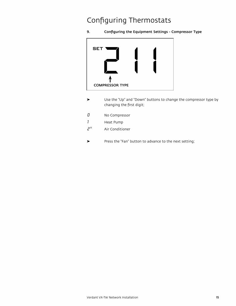
9. Configuring the Equipment Settings - Compressor Type
➤ Use the “Up” and “Down” buttons to change the compressor type by
changing the first digit;
0 No compressor
1 Heat Pump
2 * Air conditioner
➤ Press the “Fan” button to advance to the next setting;

ELECTRIC HEAT
16 Verdant VX-tW Network Installation
configuring thermostats
10. Configuring the Equipment Settings - Electric Heat
➤ Use the “Up” and “Down” buttons to change the electric Heat
setting by changing the second digit;
0 No electric Heat
1 * electric Heat
➤ Press the “Fan” button to advance to the next setting;

REVERSING VALVE
17Verdant VX-tW Network Installation
configuring thermostats
11. Configuring the Equipment Settings - Reversing Valve
➤ Use the “Up” and “Down” buttons to change the reversing Valve
setting by changing the third digit;
0 energizes the PtAc Ob valve to cOOL;
1 * energizes the PtAc Ob valve to HeAt;
refer to the PtAc unit documentation to determine the correct Ob
VALVe setting.
If incorrect Ob VALVe Setting is selected, the PtAc unit will turn on
the heating when air conditioning is requested and turn on the air
conditioning when heating is requested;
➤ Press the “Fan” button to advance to the next setting;
➤ Press the “F/c” button to advance to the next menu;

18 Verdant VX-tW Network Installation
configuring thermostats
12. Configuring the Energy Saving Settings
➤ Use the “Up” and “Down” buttons to select one of energy Saving
presets;
0 * energy Savings Off - No temperature Setback;
1 Lowest energy Savings;
2 Lower energy Savings;
3 Standard energy Savings;
4 Higher energy Savings;
5 Highest energy Savings ;

19Verdant VX-tW Network Installation
testing thermostats
Following the thermostat configuration, test if the thermostat is controlling the
HVAc unit.
➤ Press the “Power” button to save the thermostat configuration and
start using the thermostat;
➤ Press the “Power” button to turn the thermostat ON;
➤ Press the “Down” button to change the temperature setpoint below
the current room temperature to confirm that the thermostat
initiates air conditioning.
➤ Press the “Up” button to change the temperature setpoint above
the current room temperature to confirm that the thermostat
initiates heating.
➤ change the fan speed by touching the “Fan” button to test if the
thermostat is controlling the fan speed.

20 Verdant VX-tW Network Installation
confirming Network connectivity
confirm the thermostat is connected to the network before installing
thermostats in additional rooms;
➤ Log in to Verdant’s remote Management Website;
➤ Navigate to the property being installed.
➤ confirm that the thermostat is on the remote Management
Website with the correct room number;
IF INSTALLED THERMOSTAT(S) ARE NOT CONNECTING TO THE NETWORK AND DO NOT APPEAR ON THE VERDANT’S REMOTE MANAGEMENT WEBSITE, STOP THE INSTALLATION AND CONTACT VERDANT TECHNICAL SUPPORT

21Verdant VX-tW Network Installation
troubleshooting
Thermostat is not controlling the PTAC unit.
1. Check if the HVAC unit is set to “External Thermostat” (Class 2)
mode.
2. Verify the status of the red light on the Wireless Control Card;
➤ the red light is off
the control card is not powered. Verify the Wireless control card is
properly wired to the PtAc unit;
➤ the red light is blinking with one (1) flash
the Wireless control card is powered but it is not connected to the
thermostat, re-link the thermostat and the control card with the
Network Programmer.
➤ the red light is blinking with three (3) flashes or continuously
flashing.
the Wireless control card is connected to the thermostat - check
the wireless control card wiring and the thermostat configuration.
Low Battery indicator is displayed on the thermostat screen..
➤ replace thermostat batteries.
Error Codes
ERR 1 thermostat temperature Sensor Hardware Defect
ERR 2 thermostat radio Hardware Defect
ERR 3 thermostat radio Software Defect
ERR 4 No link with the Wireless control card
ERR 5 thermostat Memory Defect

22 Verdant VX-tW Network Installation
Warranty
HardwareVerdant environmental technologies (“Verdant”) warrants the original end user (“customer”) that new Verdant products will be free from defects in workmanship and materials, under normal use, for one (1) year from the original purchase date.
SoftwareVerdant environmental technologies warrants to customer that the Verdant thermostat software will perform in substantial conformance to its program specifications for a period of one (1) year from the date of the original purchase.
Exclusionsthis warranty excludes (1) physical damage to the surface of the product, including cracks, scratches or marks on the screen or outside casing; (2) damage caused by misuse, neglect, improper installation, unauthorized attempts to open, repair, or modify the product, or any other cause beyond the range of intended use; (3) damage caused by accident, fire, power changes, other hazard, or Acts of God; (4) damage caused by water, liquids, or foreign chemicals including condensation and humidity; or (5) use of the product with any device if such device causes the problem.
Exclusive RemediesShould a covered defect occur during the warranty period and customer notifies Verdant’s sole and exclusive remedy will be, at Verdant’s sole option and expense, to repair or replace the product. replacement products or parts may be new or reconditioned or a comparable version of the defective item. Verdant warrants any replaced product or part for a period of ninety (90) days from shipment, or through the end of the original warranty, whichever is longer.
Obtaining Warranty Serviceto obtain Warranty Service follow Verdant’s “Warranty replacement Procedure”.
Warranty ExclusivetHe FOrGOING WArrANtIeS AND reMeDIeS Are eXcLUSIVe AND IN LIeU OF ALL OtHer WArrANtIeS, eXPreSS Or IMPLIeD, INcLUDING WArrANtIeS OF MercHANtAbILItY, FItNeSS FOr A PArtIcULAr PUrPOSe, cOrreSPONDeNce WItH DeScrIPtION, AND NON-INFrINGeMeNt, ALL OF WHIcH Are eXPreSSLY DIScLAIMeD bY VerDANt eNVIrONMeNtAL tecHNOLOGIeS AND ItS SUPPLIerS.
DisclaimerNeItHer VerDANt eNVIrONMeNtAL tecHNOLOGIeS NOr ItS SUPPLIerS SHALL be LIAbLe FOr INcIDeNtAL, cONSeQUeNtIAL, INDIrect, SPecIAL, Or PUNItIVe DAMAGeS OF ANY KIND, Or FINANcIAL LOSS ArISING OUt OF Or IN cONNectION WItH tHe SALe Or USe OF tHIS PrODUct, WHetHer bASeD IN cONtrAct, tOrt (INcLUDING NeGLIGeNce) Or ANY OtHer tHeOrY, eVeN IF VerDANt eNVIrONMeNtAL tecHNOLOGIeS HAS beeN ADVISeD OF tHe POSSIbILItY OF SUcH DAMAGeS. VerDANt eNVIrONMeNtAL tecHNOLOGIeS’ eNtIre LIAbILItY SHALL be LIMIteD tO rePLAceMeNt Or rePAIr OF tHe PrODUct.

BLANK PAGE

US PAteNtS: 8,369,994; 8,141,791; 7,918,406; 7,841,542; 7,838,803; re40,437; 7,232,075; 7,185,825; 7,156,318; 7,152,806; 7,145,110; 7,058,477; 7,050,026; 7,028,912; 6,902,117; 6,789,739;
6,786,421; 6,619,555; 6,581,846; 6,578,770; cANADIAN PAteNtS: cA2615065; cA2633113; cA2633121; cA2633200; OtHer PAteNtS PeNDING.
Verdant environmental technologies, Inc. reserves the right to make changes, without notice, in design or components as progress in engineering and manufacturing methods may warrant. Product appearance may vary.
© Verdant environmental technologies, Inc. 2015. Printed in canada. V.4 October 20, 2015
Fcc ID: XeYVX
Ic: 8410A-VX
tHIS DeVIce cOMPLIeS WItH PArt 15 OF tHe Fcc rULeS. OPerAtION IS SUbJect tO tHe FOLLOWING tWO cONDItIONS: (1) tHIS DeVIce MAY NOt cAUSe HArMFUL INterFereNce, AND (2) tHIS DeVIce MUSt AccePt ANY INterFereNce receIVeD, INcLUDING INterFereNce tHAt MAY cAUSe UNDeSIreD OPerAtION.
PUrSUANt tO PArt 15.21 OF tHe Fcc rULeS, ANY cHANGeS Or MODIFIcAtIONS tO tHIS eQUIPMeNt NOt eXPreSSLY APPrOVeD bY VerDANt eNVIrONMeNtAL tecHNOLOGIeS, INc. MAY VOID VOID tHe USer’S AUtHOrItY tO OPerAte tHe eQUIPMeNt.
Verdant environmental technologies
5667 royalmount Avenue
Montreal, Quebec, H4P 2P9, canada
+1 (888) 440-0991
+1 (514) 344-4448
www.verdant.info
technical Specifications
thermostat Wireless control card
case Dimensions (Imperial)
5.125 x 4.6875” x 1.25” 3.875” x 2.125” x 0.75”
case Dimensions (Metric)
130mm x 119mm x 32mm 98mm x 54mm x 19mm
Screen Dimensions (Imperial)
3.625" x 2.125" N/A
Screen Dimensions (Metric)
92mm x 54mm N/A
Operating Voltage 3V Dc - 2 "c" cell batteries 24V Ac/Dc
control Outputs Fan High (GH)
Fan Low (GL)
compressor (Y)
Heat Pump (Ob)
electric Heat (W2)
Occupancy Sensor beam Width
±47° (94°) N/A
Wireless Frequency 900MHz 900MHz
temperature Accuracy ±1°F N/A