Embed Size (px)
Citation preview
Disposal of Old Equipment and BatteriesOnly for European Union and countries with recycling systems
These symbols on the products, packaging, and/or accompanying documents mean that used electrical
and electronic products and batteries must not be mixed with general household waste.
For proper treatment, recovery and recycling of old products and used batteries, please take them to
applicable collection points in accordance with your national legislation.
By disposing of them correctly, you will help to save valuable resources and prevent any potential
negative effects on human health and the environment.
For more information about collection and recycling, please contact your local authority.
Penalties may be applicable for incorrect disposal of this waste, in accordance with national legislation.
Note for the battery symbol (bottom symbol)This symbol might be used in combination with a chemical symbol. In this case it complies with the
requirement set by the Directive for the chemical involved.
Template ..........................................................1 pc.
U2140 U2130Cable for easy kitting*2 .....................................1 pc.
U2540 U2530RJ45 waterproof connector cover ...................1 pc.
RJ45 waterproof connector cap ......................1 pc.
Bit (Hex wrench, screw size 6.35 mm
{1/4 inches} T10) ........................................1 pc.
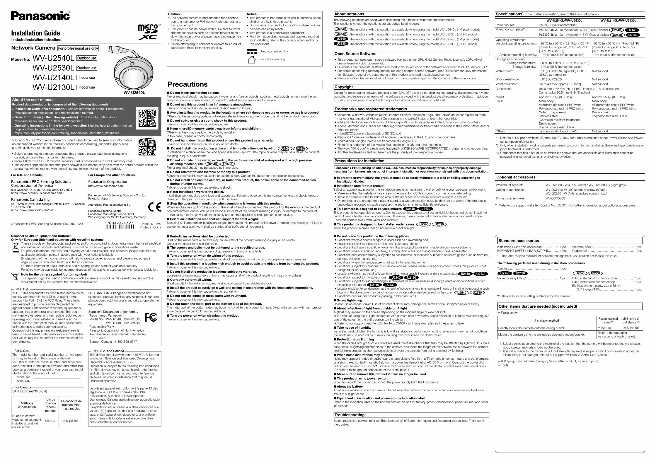
Model No. WV-U2540L Outdoor use
WV-U2530L Outdoor use
WV-U2140L Indoor use
WV-U2130L Indoor use
• Before attempting to connect or operate this product, please read these instructions
carefully and save this manual for future use.
• microSDXC/ microSDHC/ microSD memory card is described as microSD memory card.
• The external appearance and other parts shown in this manual may differ from the actual product within the
scope that will not interfere with normal use due to improvement of the product.
About the user manualsProduct documentation is composed of the following documents.
• Installation Guide (this document): Provides information about “Precautions”,
“Precautions for installation” and the installation method.
• Basic Information (in the following website): Provides information about
“Precautions for use” and “Detail specifications”.
• Operating Instructions (in the following website): Explains how to perform the set-
tings and how to operate this camera.
https://security.panasonic.com/training_support/documentation_database/
Trademarks and registered trademarks• Microsoft, Windows, Windows Media, Internet Explorer, Microsoft Edge, and ActiveX are either registered trade-
marks or trademarks of Microsoft Corporation in the United States and/or other countries.
• Intel and Intel Core are trademarks of Intel Corporation or its subsidiaries in the U.S. and/or other countries.
• Adobe, Acrobat, and Reader are either registered trademarks or trademarks of Adobe in the United States and/or
other countries.
• microSDXC Logo is a trademark of SD-3C, LLC.
• iPad and iPhone are trademarks of Apple Inc., registered in the U.S. and other countries.
• Android and Google Chrome are trademark of Google LLC.
• Firefox is a trademark of the Mozilla Foundation in the US and other countries.
• The word "QR Code" is a registered trademark of DENSO WAVE INCORPORATED in Japan and other countries.
• All other trademarks identified herein are the property of their respective owners.
Open Source Software• This product contains open source software licensed under GPL (GNU General Public License), LGPL (GNU
Lesser General Public License), etc.
• Customers can duplicate, distribute and modify the source code of the software under license of GPL and/or LGPL.
• For details concerning licensing and source code of open source software, click “Click here for OSS information”
on “Support” page of the setup menu of this product and read the displayed content.
• Please note that Panasonic shall not respond to any inquiries regarding the contents of the source code.
CopyrightExcept for open source software licensed under GPL/LGPL and so on, distributing, copying, disassembling, reverse
compiling and reverse engineering of the software provided with this product are all expressly prohibited. In addition,
exporting any software provided with this product violating export laws is prohibited.
Installation GuideIncluded Installation Instructions
Network Camera For professional use only
■ Do not insert any foreign objects. Fire or electrical shock may be caused if water or any foreign objects, such as metal objects, enter inside the unit.
Turn the power off immediately and contact qualified service personnel for service.
■ Do not use this product in an infl ammable atmosphere. Failure to observe this may cause an explosion resulting in injury.
■ Avoid installing this product in the locations where salt damage occurs or corrosive gas is produced.Otherwise, the mounting portions will deteriorate and injury or accidents due to a fall of the product may occur.
■ Do not strike or give a strong shock to this product.Failure to observe this may cause injury or fire.
■ Keep microSD memory cards away from infants and children.Otherwise, they may swallow the cards by mistake.
In this case, consult a doctor immediately.
■ Do not hang down from this product or use this product as a pedestal. Failure to observe this may cause injury or accidents.
■ Do not install this product on a place that is greatly infl uenced by wind. U2540 U2530Installation on a place where the wind speed is 60 m/s {approx. 134 mph} or more may cause a fall of the product
resulting in injury or accidents.
■ Do not sprinkle more water, exceeding the performance limit of waterproof with a high pressure cleaning machine, etc. U2540 U2530
Fire or electrical shock may be caused by immersion.
■ Do not attempt to disassemble or modify this product. Failure to observe this may cause fire or electric shock. Consult the dealer for the repair or inspections.
■ Do not install or clean the camera, or touch this product, the power cable or the connected cables during thunder storms.
Failure to observe this may cause electric shock.
■ Refer installation work to the dealer. Installation work requires technique and experience. Failure to observe this may cause fire, electric shock, injury, or
damage to the product. Be sure to consult the dealer.
■ Stop the operation immediately when something is wrong with this product. When smoke goes up from the product, the smell of smoke comes from the product, or the exterior of the product
has deteriorated, continued use will cause a fire or fall of the product resulting in injury, or damage to the product.
In this case, turn the power off immediately and contact qualified service personnel for service.
■ Select an installation area that can support the total weight. Selecting an inappropriate installation surface may cause this product to fall down or topple over, resulting in injury or
accidents. Installation work shall be started after sufficient reinforcement.
■ Periodic inspections shall be conducted. Rust on the metal parts or screws may cause a fall of the product resulting in injury or accidents.
Consult the dealer for the inspections.
■ The screws and bolts must be tightened to the specifi ed torque.Failure to observe this may cause a drop resulting in injury or accidents.
■ Turn the power off when do wiring of this product.Failure to observe this may cause electric shock. In addition, short circuit or wrong wiring may cause fire.
■ Install this product in a location high enough to avoid people and objects from bumping the product. Failure to observe this may cause injury.
■ Do not install this product in locations subject to vibration.Loosening of mounting screws or bolts may cause a fall of the product resulting in injury or accidents.
■ Correctly perform all wiring.Short circuits in the wiring or incorrect wiring may cause fire or electrical shock.
■ Install the product securely on a wall or a ceiling in accordance with the installation instructions.Failure to observe this may cause injury or accidents.
■ Do not rub the edges of metal parts with your hand.Failure to observe this may cause injury.
■ Do not touch the metal part of the bottom side of the product. The metal part of the bottom side may become hot while the product is in use. Direct skin contact with high-temper-
ature parts of the product may cause burns.
■ Turn the power off when cleaning this product.Failure to observe this may cause injury.
Precautions
Caution:• The network camera is only intended for a connec-
tion to an ethernet or PoE network without routing to
the outside plant.
• This product has no power switch. Be sure to install
disconnect devices such as a circuit breaker to shut
down the main power of power supplying equipment
to this product.
• Before attempting to connect or operate this product,
please read these instructions carefully.
Notice:• This product is not suitable for use in locations where
children are likely to be present.
• Do not install this product in locations where ordinary
persons can easily reach.
• This product is a professional equipment.
• For information about screws and brackets required
for installation, refer to the corresponding section of
this document.
: Direct current symbol
: For indoor use only
About notations
NOTE: This equipment has been tested and found to
comply with the limits for a Class A digital device,
pursuant to Part 15 of the FCC Rules. These limits
are designed to provide reasonable protection
against harmful interference when the equipment is
operated in a commercial environment. This equip-
ment generates, uses, and can radiate radio frequen-
cy energy and, if not installed and used in accor-
dance with the instruction manual, may cause harm-
ful interference to radio communications.
Operation of this equipment in a residential area is
likely to cause harmful interference in which case the
user will be required to correct the interference at his
own expense.
FCC CAUTION: Changes or modifications not
expressly approved by the party responsible for com-
pliance could void the user's authority to operate the
equipment.
Supplier’s Declaration of conformity
Trade name : Panasonic
Model No. : WV-U2540L, WV-U2530L
WV-U2140L, WV-U2130L
Responsible Party :
Panasonic Corporation of North America
Two Riverfront Plaza, Newark, New Jersey
07102-5490
Support Contact : 1-800-528-6747
For U.S.A.
CAN ICES-3(A)/NMB-3(A)
For Canada
The model number and serial number of this prod-
uct may be found on the surface of the unit.
You should note the model number and serial num-
ber of this unit in the space provided and retain this
book as a permanent record of your purchase to aid
identification in the event of theft.
Model No.
Serial No.
For U.S.A.
This device complies with part 15 of FCC Rules and
Innovation, Science and Economic Development
Canada’s licence-exempt RSS(s).
Operation is subject to the following two conditions
: (1)This device may not cause harmful interference,
and (2) this device must accept any interference
received, including interference that may cause
undesired operation.
Le présent appareil est conforme à la partie 15 des
règles de la FCC et aux normes des CNR
d’Innovation, Sciences et Développement
économique Canada applicables aux appareils radio
exempts de licence.
L'exploitation est autorisée aux deux conditions sui-
vantes : (1) l'appareil ne doit pas produire de brouil-
lage, et (2) l'appareil doit accepter tout brouillage
subi, même si le brouillage est susceptible d'en
compromettre le fonctionnement.
For U.S.A. and Canada
"<Control No.: C****>" used in these documents should be used to search for information
on our support website (https://security.panasonic.com/training_support/support/info/)
and will guide you to the right information.
The following notations are used when describing the functions limited for specified models.
The functions without the notations are supported by all models.
U2540 The functions with this notation are available when using the model WV-U2540L (4M pixel model).
U2530 The functions with this notation are available when using the model WV-U2530L (Full HD model).
U2140 The functions with this notation are available when using the model WV-U2140L (4M pixel model).
U2130 The functions with this notation are available when using the model WV-U2130L (Full HD model).
For U.S. and Canada:
Panasonic i-PRO Sensing Solutions Corporation of America800 Gessner Rd, Suite 700 Houston, TX 77024https://www.security.us.panasonic.com/
Panasonic Canada Inc.5770 Ambler Drive, Mississauga, Ontario, L4W 2T3 Canada1-877-495-0580https://www.panasonic.com/ca/
© Panasonic i-PRO Sensing Solutions Co., Ltd. 2020
For Europe and other countries:
Panasonic Corporationhttp://www.panasonic.com
Panasonic i-PRO Sensing Solutions Co., Ltd. Fukuoka, Japan
Authorised Representative in EU:
Panasonic Testing CentrePanasonic Marketing Europe GmbHWinsbergring 15, 22525 Hamburg, Germany
Méthode
d’installation
Vis de
fi xation
recom-
mandée
La capacité de
traction mini-
male requise
Quand la caméra
vidéo est directement
installée au plafond
ou sur le mur.
M4/2 él. 196 N {44 lbf}
WV-U2540L
TroubleshootingBefore requesting service, refer to “Troubleshooting” of Basic Information and Operating Instructions. Then, confirm
the trouble.
Precautions for installation
■ In order to prevent injury, the product must be securely mounted to a wall or ceiling according to Installation Guide.
■ Installation area for this productSelect an appropriate place for the installation area (such as a strong wall or ceiling) in your particular environment.
• Make sure that the installation area is strong enough to hold this product, such as a concrete ceiling.
• Install the camera in the foundation area of the architecture or where sufficient strength is assured.
• Do not mount the product on a plaster board or a wooden section because they are too weak. If the product is
unavoidably mounted on such a section, the section shall be sufficiently reinforced.
■ This camera is designed to be used indoors U2140 U2130This product is not operable outdoors. Do not expose this camera to direct sunlight for hours and do not install the
product near a heater or an air conditioner. Otherwise, it may cause deformation, discoloration and malfunction.
Keep this camera away from water and moisture.
■ This product is designed to be installed under eaves. U2540 U2530Install the product in areas that do not receive direct sunlight.
■ Do not place this product in the following places• Locations where a chemical agent is used such as a swimming pool
• Locations subject to moisture or oil smoke such as a kitchen
• Locations that have a specific environment that is subject to an inflammable atmosphere or solvents
• Locations where a radiation, an X-ray, a strong radio wave or a strong magnetic field is generated
• Locations near coasts directly subjected to sea breezes, or locations subject to corrosive gases such as from hot
springs, volcanic regions, etc.
• Locations where the temperature is not within the specified range
• Locations subject to vibrations, such as on vehicles, marine vessels, or above product lines (This product is not
designed for on-vehicle use.)
• Locations where it may get directly wet from rain or water splash (including under the eaves, etc.) U2140 U2130• Locations subject to moisture or dust U2140 U2130• Locations subject to sudden changes in temperature such as near air discharge vents of air conditioners or air
circulation inlet doors U2140 U2130• Locations subject to condensation as the result of severe changes in temperature (In case of installing the product in such
locations, the dome cover may become foggy or condensation may be caused on the cover.) U2540 U2530• Locations near rubber products (packing, rubber feet, etc.)
■ Screw tighteningDo not use an impact driver. Use of an impact driver may damage the screws or cause tightening excessively.
■ About refl ection of light from outside or IR lightA ghost may appear on the screen depending on the incident angle of external light.
In the case of using the IR light, installation of a camera near a wall may cause reflection of infrared rays resulting in a
part of the screen or the entire screen turning whitish.
• Refer to our support website <Control No.: C0109> for image examples and measures to take.
■ Take notice of humidityInstall this product when the humidity is low. If installation is performed when it is raining or in very humid conditions,
the inside may be affected by humidity, causing mist-over inside the dome cover.
■ Protection from lightningWhen the cables brought from outdoors are used, there is a chance that they may be affected by lightning. In such a
case, install a lightning arrestor close to the camera, and make the length of the network cable between the camera
and lightning arrestor as short as possible to prevent the camera from being affected by lightning.
■ When noise disturbance may happenNoise may appear in video or audio near a strong electric field from a TV or radio antenna, motors and transformers,
or a strong electric field/magnetic field from a power line (lamp line) of AC100 V or more. Conduct the power distri-
bution work to keep 1 m {3-15/16 inches} away from them or conduct the electric conduit work using metal pipes.
(Be sure to make ground connection of the metal pipes.)
■ Make sure to remove this product if it will no longer be used. ■ This product has no power switch.
When turning off the power, disconnect the power supply from the PoE device.
■ About the batteryA battery is installed inside the camera. Do not leave the battery exposed in environments of excessive heat as a
result of sunlight or fire.
■ Equipment classifi cation and power source indication labelRefer to the indication label on the bottom side of this unit for the equipment classification, power source, and other
information.
Specifications* *For further information, refer to the Basic Information.
WV-U2540L/WV-U2530L WV-U2140L/WV-U2130LPower source*1: PoE (IEEE802.3af compliant)
Power consumption*1: PoE DC 48 V: 110 mA/Approx. 5.3W (Class 2 device) U2540 U2140PoE DC 48 V: 100 mA/Approx. 4.8 W (Class 2 device) U2530 U2130
Operating environment
Ambient operating temperature:
Ambient operating humidity:
–30 °C to +50 °C {–22 °F to +122 °F}
(Power On range: –20 °C to +50 °C
{–4 °F to +122 °F})
10 % to 100 % (no condensation)
–10 °C to +50 °C {14 °F to 122 °F}
(Power On range: 0 °C to 50 °C
{32 °F to 122 °F})
10 % to 90 % (no condensation)
Storage environment
Storage temperature:
Storage humidity:
–30 °C to +60 °C {–22 °F to +140 °F}
10 % to 95 % (no condensation)
Waterproof*2: IP66 (IEC 60529), Type 4X (UL50E)
NEMA 4X compliant
Not support
Shock resistance: IK10 (IEC 62262) Not support
Wind resistance: Up to 40 m/s {approx. 89 mph} Not support
Dimensions: ø109 mm × 62 mm (H) {ø4-9/32 inches × 2-7/16 inches (H)}
Dome radius 30.5 mm {1-3/16 inches}
Mass: Approx. 270 g {0.60 lbs} Approx. 250 g {0.55 lbs}
Finish: Main body:
Aluminum die cast, i-PRO white
Polycarbonate resin, i-PRO white
Outer fixing screws:
Stainless steel
(Corrosion-resistant treatment)
Dome cover:
Polycarbonate resin, Clear
Main body:
Aluminum die cast, i-PRO white
Polycarbonate resin, i-PRO white
Dome cover:
Polycarbonate resin, Clear
Others: Tamper-resistant enclosure*3 Not support
*1 Refer to our support website <Control No.: C0106> for further information about Power source and Power
consumption information.
*2 Only when installation work is properly performed according to the Installation Guide and appropriate water-
proof treatment is performed.
*3 Component that has a structure on which the screws that are accessible after installation cannot be
screwed or unscrewed using an ordinary screwdriver.
Standard accessories
*1 This label may be required for network management. Use caution not to lose this label.
The following parts are used during installation procedures.
Other items that are needed (not included)
• Fixing screw
Optional accessories*1
Wall mount bracket: WV-QWL500-W (i-PRO white) / WV-QWL500-G (Light gray)
Ceiling mount bracket: WV-QCL100-W (ISO standard screw thread) /
WV-QCL101-W (ANSI standard screw thread)
Dome cover (smoke): WV-QDC500S
*1 Refer to our support website <Control No.: C0501> for further information about optional accessories.
• RJ45plug, Ethernet cable (category 5e or better, straight, 4 pairs (8 pins))
• Tools
Installation Guide (this document) ....................1 pc.
IMPORTANT SAFETY INSTRUCTIONS ............1 pc.
Warranty card ..................................................1 pc.
Code label*1.....................................................1 pc.
Installation methodRecommended
screw*1
Minimum pull-
out strength*2
Directly mount the camera onto the ceiling or wall. M4/2 pcs. 196 N {44 lbf}
Mount the camera using the exclusively designed mount bracket.Refer to the operating
instructions of each bracket.
*1 Select screws according to the material of the location that the camera will be mounted to. In this case,
wood screws and nails should not be used.
*2 This value indicates the minimum pull-out strength required value per screw. For information about the
minimum pull-out strength, refer to our support website <Control No.: C0120>.
Panasonic i-PRO Sensing Solutions Co., Ltd. assumes no responsibility for injuries or property damage resulting from failures arising out of improper installation or operation inconsistent with this documentation.
*2 The cable for easy kitting is attached to the camera.
Ns0520-1060Printed in China
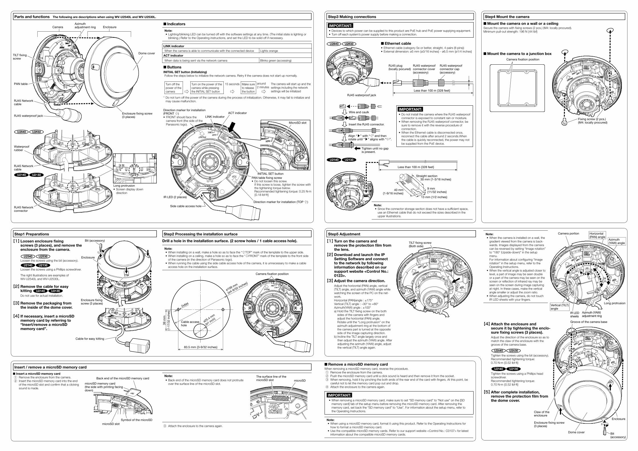
Note:• When the camera is installed on a wall, the
gradient viewed from the camera is back-
wards. Images displayed from the camera
can be reversed by setting “Image rotation”
to “180° (Upside-down)” in the setup
menu.
For information about configuring “Image
rotation” in the setup menu, refer to the
Operating Instructions.
• When the vertical angle is adjusted closer to
level, a part of image may be seen double
or a part of the camera may be seen on the
screen or reflection of infrared ray may be
seen on the screen during image capturing
at night. In these cases, make the vertical
angle smaller or adjust the zoom ratio.
• When adjusting the camera, do not touch
IR LED sheets with your fingers.
【4】 Attach the enclosure and secure it by tightening the enclo-sure fi xing screws (3 places).
Adjust the direction of the enclosure so as to
match the claw of the enclosure with the
groove of the camera base.
U2540 U2530 Tighten the screws using the bit (accessory).
Recommended tightening torque:
0.70 N·m {0.52 lbf·ft}
U2140 U2130 Tighten the screws using a Phillips head
screwdriver.
Recommended tightening torque:
0.70 N·m {0.52 lbf·ft}
【5】 After complete installation, remove the protection fi lm from the dome cover.
Step2 Processing the installation surfaceStep1 Preparations
Parts and functions The following are descriptions when using WV-U2540L and WV-U2530L.
Step5 Adjustment
■ Indicators
Note:• Lighting/blinking LED can be turned off with the software settings at any time. (The initial state is lighting or
blinking.) Refer to the Operating instructions, and set the LED to be solid off if necessary.
LINK indicator
When the camera is able to communicate with the connected device Lights orange
ACT indicator
When data is being sent via the network camera Blinks green (accessing)
■ ButtonsINITIAL SET button (Initializing)Follow the steps below to initialize the network camera. Retry if the camera does not start up normally.
Turn off the
power of the
camera ⇨
Turn on the power of the
camera while pressing
the INITIAL SET button
15 seconds Make sure
to release
the button
around
2 minutesThe camera will start up and the
settings including the network
settings will be initialized⇨ ⇨* Do not turn off the power of the camera during the process of initialization. Otherwise, it may fail to initialize and
may cause malfunction.
【1】 Turn on the camera and remove the protection fi lm from the lens.
【2】 Download and launch the IP Setting Software and connect to the network by following information described on our support website <Control No.: 0123>.
【3】 Adjust the camera direction. Adjust the horizontal (PAN) angle, vertical
(TILT) angle, and azimuth (YAW) angle while
watching the screen of the PC on the net-
work.
Horizontal (PAN)angle : ±175°
Vertical (TILT) angle : –30° to +80°
Azimuth(YAW) angle : ±100°
a) Hold the TILT fixing screw on the both
sides of the camera with fingers and
adjust the horizontal (PAN) angle.
Rotate until the “Long protrusion” on the
azimuth adjustment ring at the bottom of
the camera part is turned at the opposite
side of the image capturing direction.
b) Incline the TILT angle largely once and
then adjust the azimuth (YAW) angle. After
adjusting the azimuth (YAW) angle, adjust
the vertical (TILT) angle again.
PAN table
Camera EnclosureAzimuth adjustment ring
TILT fixing screw
Enclosure fixing screw (3 places)
Step3 Making connections Step4 Mount the camera
■ Mount the camera on a wall or a ceiling Secure the camera with fixing screws (2 pcs.) (M4: locally procured).
Minimum pull-out strength: 196 N {44 lbf}
■ Mount the camera to a junction box
IMPORTANT:• Devices to which power can be supplied to this product are PoE hub and PoE power supplying equipment.
• Turn off each system’s power supply before making a connection.
Camera fixation position
Dome cover
MicroSD slot
ACT indicator
IR LED (2 places)
Side cable access hole
INITIAL SET button
PAN table fixing screw• Do not loosen this screw.
If this screw is loose, tighten the screw with the tightening torque below.Recommended tightening torque: 0.25 N·m {0.18 lbf·ft}
Direction marker for installation (TOP ⇧)
LINK indicator
Direction marker for installation (FRONT ⇩)
• FRONT should face the
camera front (the side of the
Panasonic logo).
RJ45 waterproof jack
RJ45 Network cable
RJ45 Networkcable
RJ45 Network connector
Waterproofrubber
U2540 U2530
U2140 U2130
【1】 Loosen enclosure fi xing screws (3 places), and remove the enclosure from the camera.
U2540 U2530Loosen the screws using the bit (accessory).
U2140 U2130Loosen the screws using a Phillips screwdriver.
The right illustrations are examples of
WV-U2540L and WV-U2530L.
【2】 Remove the cable for easy kitting U2140 U2130Do not use for actual installation.
【3】 Remove the packaging from the inside of the dome cover.
【4】 If necessary, insert a microSD memory card by referring to “Insert/remove a microSD memory card”.
Bit (accessory)
Enclosure
Enclosure fixing screw (3 places)
■ Insert a microSD memory card q Remove the enclosure from the camera.
w Insert the microSD memory card into the end
of the microSD slot and confirm that a clicking
sound is made.
■ Remove a microSD memory cardWhen removing a microSD memory card, reverse the procedure.
q Remove the enclosure from the camera.
w Push the microSD memory card until a click sound is heard and then remove it from the socket.
e When removing, hold it by pinching the both ends of the rear end of the card with fingers. At this point, be
careful not to let the memory card pop out and drop.
r Attach the enclosure to the camera again.
IMPORTANT:• When removing a microSD memory card, make sure to set “SD memory card” to “Not use” on the [SD
memory card] tab of the setup menu before removing the microSD memory card. After removing the
memory card, set back the “SD memory card” to “Use”. For information about the setup menu, refer to
the Operating Instructions.
Note:• When using a microSD memory card, format it using this product. Refer to the Operating Instructions for
how to format a microSD memory card.
• Use the compatible microSD memory cards. Refer to our support website <Control No.: C0107> for latest
information about the compatible microSD memory cards.
Insert / remove a microSD memory card
Back end of the microSD memory card
microSD memory card (the side with printing facing down)
Symbol of the microSD
microSD slot
Drill a hole in the installation surface. (2 screw holes / 1 cable access hole).
Note:• When installing on a wall, make a hole so as to face the “⇧TOP” mark of the template to the upper side.
• When installing on a ceiling, make a hole so as to face the “⇩FRONT” mark of the template to the front side
of the camera (in the direction of Panasonic logo).
• When running the cable using the side cable access hole of the camera, it is unnecessary to make a cable
access hole on the installation surface.
Camera fixation position
U2540 U2530 ■ Ethernet cable• Ethernet cable (category 5e or better, straight, 4 pairs (8 pins))
• External dimension: ø5 mm {ø3/16 inches} - ø6.5 mm {ø1/4 inches}
Less than 100 m {328 feet}
RJ45 plug (locally pocured)
RJ45 waterproof connector cover (accessory)
RJ45 waterproof connector cap (accessory)
RJ45 waterproof jack
IMPORTANT:• Do not install the camera where the RJ45 waterproof
connector is exposed to constant rain or moisture.
• When removing the RJ45 waterproof connector, be
sure to remove it with the reverse procedure of
connection.
• When the Ethernet cable is disconnected once,
reconnect the cable after around 2 seconds.When
the cable is quickly reconnected, the power may not
be supplied from the PoE device.
Wire and caulk
Tighten until no gap is present.
Align “▶” with “◁” and then rotate until “▶” aligns with “⇦”.
Insert the RJ45 connector.
U2140 U2130
Less than 100 m {328 feet}
Note:• Since the connector storage section does not have a sufficient space,
use an Ethernet cable that do not exceed the sizes described in the
upper illustrations.
Straight section 30 mm {1-3/16 inches}
13 mm {1/2 inches}
9 mm {11/32 inches}
40 mm {1-9/16 inches}
Fixing screw (2 pcs.) (M4: locally procured)
TILT fixing screw(Both side)
Vertical (TILT)angle
IR LED sheets
Horizontal (PAN) angle
Azimuth (YAW)adjustment ring
Long protrusion
Note:• Back end of the microSD memory card does not protrude
over the surface line of the microSD slot.
e Attach the enclosure to the camera again.
microSD
The surface line of the microSD slot
Camera portion
Bit (accessory)
Enclosure fixing screw (3 places)
Enclosure
Groove of the camera base
Claw of the enclosure
Dome cover
Azimuth (YAW) angle
Long protrusion
• Screen display down
direction
39 m
m
{1-1
7/3
2 in
ch
es}
83.5 mm {3-9/32 inches}
ø109 mm
{ø4-9/32 inches}
ø25.4 mm
{ø1 in
ch}
Cable for easy kitting
Cable accesshole
2xM4