Embed Size (px)
Citation preview
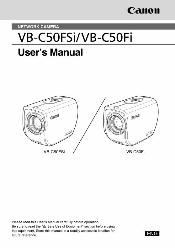
NETWORK CAMERA
User’s Manual
VB-C50Fi
Please read this User’s Manual carefully before operation.Be sure to read the “a Safe Use of Equipment” section before usingthis equipment. Store this manual in a readily accessible location forfuture reference.
VB-C50FSiCOPY
ii
Introduction
Thank you for purchasing the Canon Network Camera VB-C50FSi/VB-C50Fi (referred to hereafteras the VB-C50FSi/VB-C50Fi).This User’s Manual describes how to set up and use the VB-C50FSi/VB-C50Fi. Read this manualcarefully before using the VB-C50FSi/VB-C50Fi to ensure effective operation. In particular make surethat you read the “a Safe Use of Equipment” in this manual, as well as the supplied CD-ROM ReadMefile.For the latest information, please refer to Canon Web site.
Exclusion of Liability
If the Product is connected to a recording device (for example a VCR), Canon Inc. acceptsno responsibility whatsoever for any financial losses that may be incurred as a result ofthe loss of recorded information or images, regardless of the internal or external cause ofthe loss.
On CopyrightsVideos, images or sounds taken or recorded with your VB-C50FSi/VB-C50Fi may not be utilizedor published, without consent of copyright holders, if any, except in such a way as permitted forpersonal use under relevant copyright law.
Notes1. The unauthorized transfer of all or any part of the contents of this Manual is forbidden.2. The contents of this Manual are subject to change without notice.3. Every effort has been made to ensure that this Manual is flawless. However, if you find any
oversights, please let us know.4. Notwithstanding the above, Canon accepts no responsibility for any effects resulting from the
use of this Manual.
Trademark NoticesCanon and Canon logo are registered trademarks of Canon Inc.Microsoft and Windows are registered trademarks of Microsoft Corporation in the United States
and other countries.Windows is legally recognized as Microsoft Windows Operating System.Java and all Java-based marks are trademarks or registered trademarks of Sun Microsystems,
Inc. in the United States and other countries.Other brand or product names in this manual may be trademarks or registered trademarks of
their respective companies.
This product uses software based on the GNU General Public License (GPL), GNU Lesser General
Public License (LGPL) and the BSD License. For each of the licenses, see GPL.txt, LGPL.txt and
COPYING.txt in the LICENSE folder on the CD-ROM.
If you require the source code for a program based on GPL or LGPL, please contact either the place
of purchase or your nearest Canon Sales Company.
COPY
iii
Request concerning disclosure of live videos and audioWith respect to the disclosure of live videos and audio, we request that sufficientconsideration be given to matters of privacy and rights not to be photographed.Canon considers the following points concerning such matters when it operates camerasites for which it has been responsible to install and operate:We take measures such as adding limitations on zoom magnifications so that people
cannot make special specifications.When videos are taken of specific buildings, interiors and the like, we install the camera
only after receiving approval from the administrator.Please note that the operator of the camera site and not Canon has full responsibilityregarding the disclosure of live videos and audio.* Audio features are only available on the VB-C50FSi.
Introduction
Usage Notice of Audio (VB-C50FSi only)
* Features related to audio transmission (audio sent from camera servers to viewers)written in this manual can be only used with the Model Name “VB-C50FSiN”.Please refer to P.1-10 to confirm the Model Name of your VB-C50FSi.
The audio and video may be out of sync.* The audio stream may be interrupted according to the performance of your PC and the
network environment. You cannot record audio with the viewer software.* You can receive audio using the Viewer for PC or the Admin Viewer.* You can send audio and video to up to 50 clients. However, if there are a large number
of clients, the audio stream may be interrupted.* The audio stream may be interrupted if you use a proxy server. The audio stream may be interrupted if you use anti-virus software.
European Union (and EEA) only.This symbol indicates that this product is not to be disposed of with yourhousehold waste, according to the WEEE Directive (2002/96/EC) and yournational law. This product should be handed over to a designated collectionpoint, e.g., on an authorized one-for-one basis when you buy a new similarproduct or to an authorized collection site for recycling waste electrical and
electronic equipment (EEE). Improper handling of this type of waste could have a possiblenegative impact on the environment and human health due to potentially hazardoussubstances that are generally associated with EEE. At the same time, your cooperation inthe correct disposal of this product will contribute to the effective usage of natural resources.For more information about where you can drop off your waste equipment for recycling,please contact your local city office, waste authority, approved WEEE scheme or yourhousehold waste disposal service.For more information regarding return and recycling of WEEE products, please visitwww.canon-europe.com/environment.(EEA: Norway, Iceland and Liechtenstein)
© Copyright 2007 CANON INC.ALL RIGHTS RESERVED
COPY
iv
Package Contents
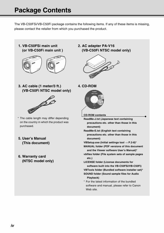
The VB-C50FSi/VB-C50Fi package contains the following items. If any of these items is missing,
please contact the retailer from which you purchased the product.
* The cable length may differ dependingon the country in which the product waspurchased.
1. VB-C50FSi main unit(or VB-C50Fi main unit )
2. AC adapter PA-V16(VB-C50Fi NTSC model only)
3. AC cable (1 meter/3 ft.)(VB-C50Fi NTSC model only)
4. CD-ROM
5. User’s Manual(This document)
6. Warranty card(NTSC model only)
CD-ROM contents
ReadMe-J.txt (Japanese text containing
precautions etc. other than those in this
document)
ReadMe-E.txt (English text containing
precautions etc. other than those in this
document)
VBSetup.exe (Initial settings tool → P.2-8)*
MANUAL folder (PDF versions of this document
and the Viewer software User’s Manual)*
vbfiles folder (File system sets of sample pages
etc.)
LICENSE folder (License documents for
software built into the VB-C50FSi/VB-C50Fi)
VBTools folder (Bundled software installer set)*
SOUND folder (Sound sample files for Audio
Playback)
* For the latest information of the bundledsoftware and manual, please refer to CanonWeb site.
COPY
v
Contents
Introduction ............................................................................ ii
Package Contents .................................................................. iv
How to Read This Manual...................................................... ix
aSafe Use of Equipment....................................................... xMaintenance .............................................................................................................. xv
Chapter 1 Before Using the VB-C50FSi/VB-C50FiFeatures of the VB-C50FSi/VB-C50Fi .......................................................... 1-2Hardware and Software Requirements ....................................................... 1-4
Viewer Software ....................................................................................................... 1-4
VB Initial Setup Tool ................................................................................................. 1-5
VB Administration Tools ........................................................................................... 1-5
VBCollector .............................................................................................................. 1-5
Multipoint Recording Software for Monitoring Use (Sold separately) ...................... 1-8
System Components and Their Operation ................................................. 1-9Multi-Terminal Module VB-EX50 (Sold Separately) .................................. 1-11
Chapter 2 Setting UpSetup Workflow ............................................................................................. 2-21. Set Up the Camera .................................................................................... 2-4
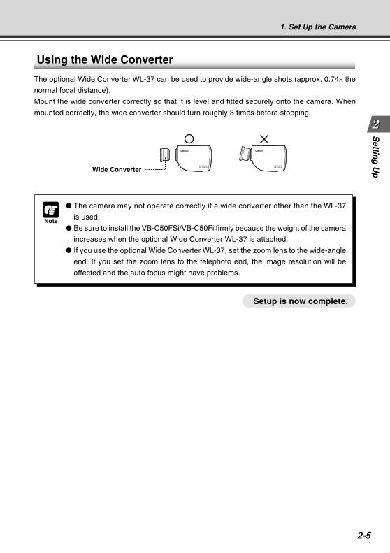
Using the Wide Converter ........................................................................................ 2-5
2. Connect the Camera to the Network ....................................................... 2-6Turning the Power ON and OFF .............................................................................. 2-7
3. Perform Initial Settings for the Camera .................................................. 2-84. Check Operation of the Camera ............................................................ 2-115. Install the Software ................................................................................. 2-13Viewer Software Overview ......................................................................... 2-14
Viewer Software Types .......................................................................................... 2-14
Features of the Viewer Software ............................................................................ 2-14
Chapter 3 Basic SettingsWhat Can I Do on Each of the Settings Pages? ......................................... 3-2Accessing the Settings Title Page ............................................................... 3-3Settings Title Page ........................................................................................ 3-4Setting Up the Administrator Password and Ethernet etc.
(System and Network) ....................................................................... 3-5Setting Camera Control, Image Size and Quality (Camera and Video) .... 3-8Presetting Best Shot (Preset) .................................................................... 3-12
COPY
vi
Contents
Setting Up the HTTP, Camera and Audio Servers (Server) ..................... 3-15Setting User Access Privileges (Access Control) ................................... 3-20Setting the Date and Time (Date and Time) .............................................. 3-23Setting Up Name Server Address and Mail etc. (Miscellaneous) ........... 3-25Using the Administration Tools (Administration Tools) .......................... 3-28
Chapter 4 VB Administration ToolsOverview of VB Administration Tools ......................................................... 4-2
Installing the VB Administration Tools ...................................................................... 4-2
VBAdmin Startup Panel ........................................................................................... 4-3
Panorama Creation Tool .......................................................................................... 4-3
View Restriction Tool ................................................................................................ 4-3
Preset Setting Tool ................................................................................................... 4-3
Schedule Setting Tool .............................................................................................. 4-4
Log Viewer ............................................................................................................... 4-4
Admin Viewer .......................................................................................................... 4-4
Starting Up VB Administration Tools .......................................................... 4-5View Restriction Tool .................................................................................... 4-7
View Restriction Tool Display Screen ...................................................................... 4-8
Setting View Restrictions ....................................................................................... 4-10
Preset Setting Tool ...................................................................................... 4-13Preset Setting Tool Display Screen ........................................................................ 4-14
Setting Presets ....................................................................................................... 4-16
Preset Tour ............................................................................................................. 4-19
Schedule Setting Tool ................................................................................. 4-22Schedule Setting Tool Display Screen (Toolbar) .................................................... 4-23
Normal Schedule ................................................................................................... 4-24
Special Schedule ................................................................................................... 4-28
Resetting Schedule Settings .................................................................................. 4-32
Setting Up Service ................................................................................................. 4-33
Timer Setting Tool .................................................................................................. 4-34
Motion Detection Setting Tool ................................................................................ 4-37
Night Mode Setting Tool ......................................................................................... 4-48
External Device Input Setting Tool ......................................................................... 4-50
External Device Output Setting Tool ...................................................................... 4-53
Log Viewer ................................................................................................... 4-58Viewing the Log ..................................................................................................... 4-59
Admin Viewer .............................................................................................. 4-61Starting Up Admin Viewer ...................................................................................... 4-62
Operating External Devices and Motion Detection ................................................ 4-62
Enabling/Disabling View Restrictions ..................................................................... 4-64
Operating a Camera .............................................................................................. 4-64
COPY
vii
Contents
Camera-Specific Functions .................................................................................... 4-66
Sending and Receiving* Audio (VB-C50FSi only) .................................................. 4-67
Shade Correction ................................................................................................... 4-69
Auto Reconnection Function .................................................................................. 4-69
Restoring the Default Exposure and Focus Settings When Closing the Admin Viewer .. 4-70
Chapter 5 Creating Web Pages for Video DistributionWeb Pages for Video Distribution ............................................................... 5-2Viewer Overview ........................................................................................... 5-4
Viewer for Java ........................................................................................................ 5-4
Viewer for PC ........................................................................................................... 5-5
Viewing Sample Pages ................................................................................. 5-6Using the Viewer for Java to Distribute Videos .......................................... 5-7
Using the Viewer for Java to Create a Web Page ................................................... 5-7
Saving Web Page Data ............................................................................................ 5-8
Example of Using the Viewer for Java to Create a Web Page ................................ 5-9
Viewer for Java Parameters ................................................................................... 5-17
Using the Viewer for PC to Distribute Videos ........................................... 5-21Setting Up the Web Server .................................................................................... 5-21
Creating wvh Files ................................................................................................. 5-22
Example of a Web page Using the Viewer for PC ................................................. 5-23
Distributing Videos Using a Browser Only ............................................... 5-24Displaying the Live Video at Access as a Still Picture ........................................... 5-24
Displaying a Specified Number Of Live Video Frames As a Video at Access ....... 5-24
Displaying Live Video from a Specified Zoom Magnification as Still Pictures ........ 5-25
Example of Video Distribution Using One Global Address .................... 5-26Distributing Still Images to a Mobile Phone ............................................. 5-27
Overwriting Sample Pages .................................................................................... 5-28
Chapter 6 Using the Picture Recording FunctionUsing the Still Picture Recording Function
Linked to an External Device ........................................................... 6-2Sample Application Combining a Door-opening Sensor .......................................... 6-2
Using the Audio Playback/Recording FunctionLinked to an External Device ........................................................... 6-4
Sample Application Combining a Speaker, Microphone and Door-opening Sensor .... 6-4
Using the Still Picture Recording Functionwith a Predetermined Schedule ....................................................... 6-6
Sample Application Using a Timer ........................................................................... 6-6
Using the Motion Detection Function with a Predetermined Schedule ... 6-8Sample application in combination with a warning device ....................................... 6-8
COPY
viii
Contents
Using VBCollector ...................................................................................... 6-11Installing VBCollector ............................................................................................. 6-12
Starting Up VBCollector ......................................................................................... 6-13
Registering a Server .............................................................................................. 6-13
Registering Tasks ................................................................................................... 6-16
Executing and Canceling Tasks ............................................................................. 6-18
Details Displayed on the Task View ....................................................................... 6-20
Starting/Stopping the Service ................................................................................ 6-20
Automatic Downloading by Notification .................................................................. 6-21
Viewing Recorded Images and Playing Back Recorded Audio .............................. 6-23
Viewing Logs .......................................................................................................... 6-32
Setting Retention Period and Disk Space .............................................................. 6-36
Chapter 7 AppendixTroubleshooting ............................................................................................ 7-2Log Messages ............................................................................................... 7-4
The VB-C50FSi/VB-C50Fi Log Messages ............................................................... 7-4
The VBCollector Log Messages ............................................................................ 7-12
Specifications ............................................................................................. 7-16External Device I/O Terminals ................................................................................ 7-17
System Configuration ................................................................................ 7-18Example of Basic System Configuration – Viewing Videos Using a Viewer .......... 7-18
Viewer Software Functions .................................................................................... 7-18
Sample Network Configurations ............................................................... 7-19Sample LAN Environment Configuration ............................................................... 7-19
Sample Configuration in an ISP Environment ........................................................ 7-19
Upgrading the Firmware Remotely ........................................................... 7-20Restoring the Factory Default Settings .................................................... 7-21
Restoring the Factory Default Settings from the AdministrationTools Page via a Web Browser ................................................................. 7-21
Restoring the Factory Default Settings from the Reset Switch .............................. 7-22
Factory Default Setting .............................................................................. 7-23Data Capacity of Recorded Pictures and Audio ...................................... 7-25
Amount of Memory ................................................................................................. 7-25
Frame Sizes ........................................................................................................... 7-25
Amount of Audio Data ............................................................................................ 7-26
Index ............................................................................................................ 7-27
COPY
ix
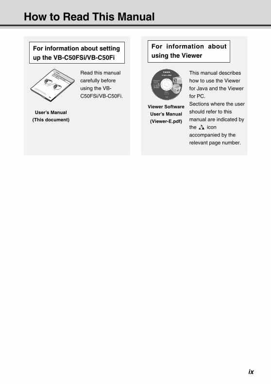
How to Read This Manual
NETWORK CAMERAUser’s Manual
Please read this instruction manual carefully before operation.
Be sure to read the “a Safe Use of Equipment” section before using
this equipment. Store this manual in a readily accessible location for
future reference.
Read this manual
carefully before
using the VB-
C50FSi/VB-C50Fi.
User’s Manual
(This document)
This manual describes
how to use the Viewer
for Java and the Viewer
for PC.
Sections where the user
should refer to this
manual are indicated by
the d icon
accompanied by the
relevant page number.
Viewer Software
User’s Manual
(Viewer-E.pdf)
For information about settingup the VB-C50FSi/VB-C50Fi
For information aboutusing the Viewer
COPY
x
a Safe Use of Equipment
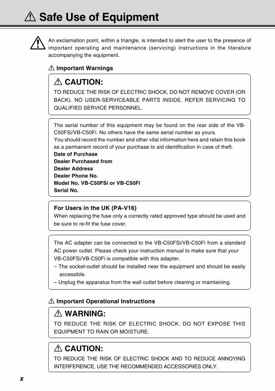
aAn exclamation point, within a triangle, is intended to alert the user to the presence ofimportant operating and maintenance (servicing) instructions in the literatureaccompanying the equipment.
a Important Operational Instructions
a Important Warnings
a CAUTION:TO REDUCE THE RISK OF ELECTRIC SHOCK, DO NOT REMOVE COVER (OR
BACK). NO USER-SERVICEABLE PARTS INSIDE. REFER SERVICING TO
QUALIFIED SERVICE PERSONNEL.
The serial number of this equipment may be found on the rear side of the VB-C50FSi/VB-C50Fi. No others have the same serial number as yours.You should record the number and other vital information here and retain this bookas a permanent record of your purchase to aid identification in case of theft.Date of PurchaseDealer Purchased fromDealer AddressDealer Phone No.Model No. VB-C50FSi or VB-C50FiSerial No.
a WARNING:TO REDUCE THE RISK OF ELECTRIC SHOCK, DO NOT EXPOSE THIS
EQUIPMENT TO RAIN OR MOISTURE.
a CAUTION:TO REDUCE THE RISK OF ELECTRIC SHOCK AND TO REDUCE ANNOYING
INTERFERENCE, USE THE RECOMMENDED ACCESSORIES ONLY.
For Users in the UK (PA-V16)When replacing the fuse only a correctly rated approved type should be used and
be sure to re-fit the fuse cover.
The AC adapter can be connected to the VB-C50FSi/VB-C50Fi from a standard
AC power outlet. Please check your instruction manual to make sure that your
VB-C50FSi/VB-C50Fi is compatible with this adapter.
– The socket-outlet should be installed near the equipment and should be easily
accessible.
– Unplug the apparatus from the wall outlet before cleaning or maintaining.
COPY
xi
FCC NOTICENetwork Camera, Model Name: VB-C50FSiN, VB-C50FSiP, VB-C50FiN, VB-C50FiP
This device complies with Part 15 of the FCC Rules. Operation is subject to thefollowing two conditions: (1) This device may not cause harmful interference,and (2) this device must accept any interference received, including interferencethat may cause undesired operation.Note: This equipment has been tested and found to comply with the limits for aClass B digital device, pursuant to Part 15 of the FCC Rules. These limits aredesigned to provide reasonable protection against harmful interference in aresidential installation. This equipment generates, uses and can radiate radiofrequency energy and, if not installed and used in accordance with theinstructions, may cause harmful interference to radio communications.However, there is no guarantee that interference will not occur in a particularinstallation. If this equipment does cause harmful interference to radio ortelevision reception, which can be determined by turning the equipment off andon, the user is encouraged to try to correct the interference by one or more ofthe following measures: - Reorient or relocate the receiving antenna. - Increase the separation between the equipment and receiver. - Connect the equipment into an outlet on a circuit different from that to which
the receiver is connected. - Consult the dealer or an experienced radio/TV technician for help.Use of shielded cable is required to comply with class B limits in Subpart B ofPart 15 of FCC Rules.Do not make any changes or modifications to the equipment unless otherwisespecified in the manual. If such changes or modifications should be made, youcould be required to stop operation of the equipment.Canon U.S.A. Inc.One Canon Plaza, Lake Success, NY 11042, U.S.A.Tel No. (516) 328-5600
a Safe Use of Equipment
Canadian Radio Interference RegulationsThis Class B digital apparatus complies with Canadian ICES-003.
Réglementation canadienne sur les intérferences radioCet appareil numérique de la classe B est conforme à la norme NMB-003 duCanada.
Dieses Produkt ist zum Gebrauch im Wohnbereich, Geschäfts- undGewerbebereich sowie in Kleinbetrieben vorgesehen.
FDA regulationThis Network Camera has not been evaluated by the Food and Drug Administration(FDA) for use as a medical device. When incorporated into a system with medicalapplications, FDA regulations may apply. Therefore, please consult your legaladvisor to determine whether FDA regulations apply.
COPY
xii
a IMPORTANT SAFETY INSTRUCTIONS
In these safety instructions, the word“equipment” refers to the Canon NetworkCamera VB-C50FSi/VB-C50Fi and all itsaccessories.
1. Read Instructions - All the safety andoperating instructions should be read beforethe equipment is operated.
2. Retain Instructions - The safety and operatinginstructions should be retained for futurereference.
3. Heed Warnings - All warnings on theequipment and in the operating instructionsshould be adhered to.
4. Follow Instructions - All operating andmaintenance instructions should be followed.
5. Cleaning - Unplug this equipment from thewall outlet before cleaning.Wipe the equipment with a clean soft cloth. Ifnecessary, put a cloth in diluted neutraldetergent and wring it well before wiping theequipment with it. Finally, clean theequipment with a clean dry cloth. Do not usebenzene, thinner or other volatile liquids orpesticides as they may damage the product’sfinish. When using chemically-treatedcleaning cloths, observe those precautionsaccordingly.
6. Accessories - Do not use accessories notrecommended in this manual as they maybe hazardous. Always use specifiedconnection cables. Connect devices correctly.
7. Water and Moisture - Hazard of electric shock- Do not use the equipment near water or inrainy/moist situations. Do not put a heaternear this equipment.
8. Placing or Moving - Do not place on anunstable cart, stand, tripod, bracket or table.The equipment may fall, causing seriousinjury to a child or adult, andserious damage to theequipment. An equipment andcart combination should bemoved with care.
Quick stops, excessive force, and unevensurfaces may cause the equipment and cartcombination to overturn.
9. Power Sources - The PA-V16 AC adaptershould be operated only from the type of powersource indicated on the marking label. If youare not sure of the type of power supply to yourhome, consult your equipment dealer or localpower company.
10. Polarization - The PA-V16 AC adapter isequipped with a polarized 2-prong plug (a plughaving one blade wider than the other).The 2-prong polarized plug will fit into thepower outlet only one way. This is a safetyfeature. If you are unable to insert the plugfully into the outlet, try reversing the plug. Ifthe plug still fails to fit, contact your electricianto replace your obsolete outlet. Do not defeatthe safety purpose of the polarized plug.
11. Power Cord Protection - Power cords shouldbe routed so that they are not likely to bewalked on or pinched by items placed uponor against them. Pay particular attention toplugs and the point from which the cords exitthe equipment.
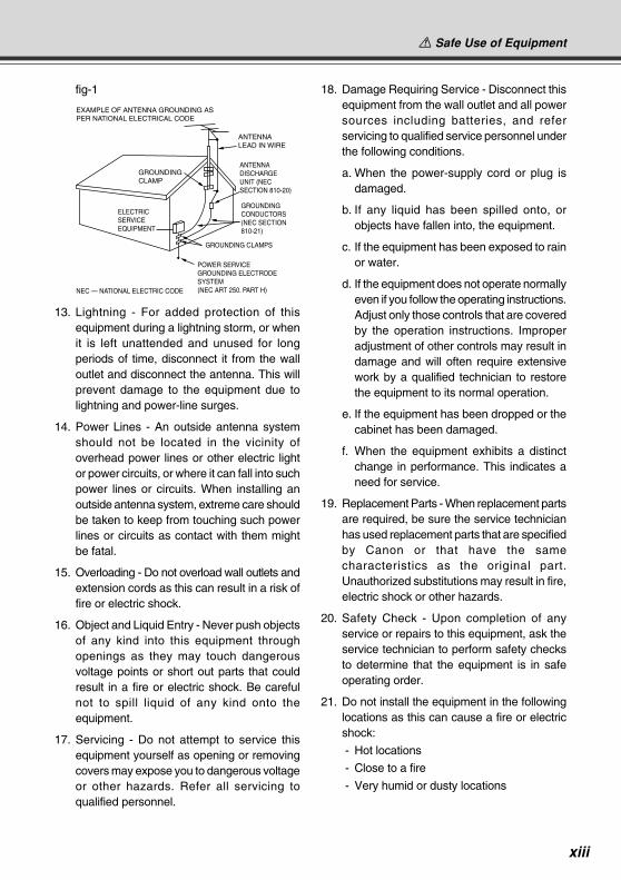
12. Outdoor Antenna Grounding - If an outsideantenna is connected to the equipment, besure the antenna is grounded so as to providesome protection against voltage surges andbuilt-up static charges. Section 810 of theNational Electrical Code, ANSI/NFPA No.70-1984, provides information with respect toproper grounding of the mast and supportingstructure, grounding of the lead-in wire to anantenna discharge unit, size of groundingconductors, location of antenna, antennadischarge unit, connection to groundingelectrodes, and requirements for thegrounding electrode. See figure 1.
a Safe Use of Equipment
COPY
xiii
fig-1
EXAMPLE OF ANTENNA GROUNDING AS PER NATIONAL ELECTRICAL CODE
ANTENNA LEAD IN WIRE
ANTENNA DISCHARGE UNIT (NEC SECTION 810-20)
GROUNDING CONDUCTORS (NEC SECTION 810-21)
GROUNDING CLAMPS
POWER SERVICE GROUNDING ELECTRODE SYSTEM(NEC ART 250. PART H)NEC — NATIONAL ELECTRIC CODE
ELECTRIC SERVICE EQUIPMENT
GROUNDING CLAMP
13. Lightning - For added protection of thisequipment during a lightning storm, or whenit is left unattended and unused for longperiods of time, disconnect it from the walloutlet and disconnect the antenna. This willprevent damage to the equipment due tolightning and power-line surges.
14. Power Lines - An outside antenna systemshould not be located in the vicinity ofoverhead power lines or other electric lightor power circuits, or where it can fall into suchpower lines or circuits. When installing anoutside antenna system, extreme care shouldbe taken to keep from touching such powerlines or circuits as contact with them mightbe fatal.
15. Overloading - Do not overload wall outlets andextension cords as this can result in a risk offire or electric shock.
16. Object and Liquid Entry - Never push objectsof any kind into this equipment throughopenings as they may touch dangerousvoltage points or short out parts that couldresult in a fire or electric shock. Be carefulnot to spill liquid of any kind onto theequipment.
17. Servicing - Do not attempt to service thisequipment yourself as opening or removingcovers may expose you to dangerous voltageor other hazards. Refer all servicing toqualified personnel.
18. Damage Requiring Service - Disconnect thisequipment from the wall outlet and all powersources including batteries, and referservicing to qualified service personnel underthe following conditions.
a. When the power-supply cord or plug isdamaged.
b. If any liquid has been spilled onto, orobjects have fallen into, the equipment.
c. If the equipment has been exposed to rainor water.
d. If the equipment does not operate normallyeven if you follow the operating instructions.Adjust only those controls that are coveredby the operation instructions. Improperadjustment of other controls may result indamage and will often require extensivework by a qualified technician to restorethe equipment to its normal operation.
e. If the equipment has been dropped or thecabinet has been damaged.
f. When the equipment exhibits a distinctchange in performance. This indicates aneed for service.
19. Replacement Parts - When replacement partsare required, be sure the service technicianhas used replacement parts that are specifiedby Canon or that have the samecharacteristics as the original part.Unauthorized substitutions may result in fire,electric shock or other hazards.
20. Safety Check - Upon completion of anyservice or repairs to this equipment, ask theservice technician to perform safety checksto determine that the equipment is in safeoperating order.
21. Do not install the equipment in the followinglocations as this can cause a fire or electricshock:
- Hot locations
- Close to a fire
- Very humid or dusty locations
a Safe Use of Equipment
COPY
xiv
- Locations exposed to direct sunlight
- Locations exposed to salt spray
- Close to flammable solvents (alcohol,thinners, etc.)
22. When any of the following occurs,immediately switch OFF the equipment,unplug it from the main power supply andcontact your nearest Canon supplier. Do notcontinue to use the equipment as this cancause a fire or electric shock.
- The equipment emits any smoke, heat,abnormal noise, or unusual odor.
- A metal object falls into the equipment.
- The equipment is damaged in some way.
23. Please observe the following when using theequipment. Failure to do so can result in afire or electric shock.
- Do not use flammable sprays near theequipment.
- Do not subject the equipment to strongimpacts.
24. Make sure the power line and network cableare implemented in a safe manneraccordingly to the related technicalregulations.
25. Focusing on the direct sunlight, halogenlamp or any other high-intensity lamp for along time may cause damage to the imagesensor.
a Safe Use of Equipment
For CA, USA onlyIncluded lithium battery contains Perchlorate Material – special handling may apply.
See www.dtsc.ca.gov/hazardouswaste/perchlorate/ for details.
COPY
xv
a Safe Use of Equipment
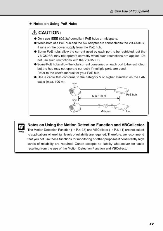
a Notes on Using PoE Hubs
a CAUTION: Only use IEEE 802.3af-compliant PoE hubs or midspans. When both of a PoE hub and the AC Adapter are connected to the VB-C50FSi,
it runs on the power supply from the PoE hub. Some PoE hubs allow the current used by each port to be restricted, but the
VB-C50FSi may not operate correctly when such restrictions are applied. Donot use such restrictions with the VB-C50FSi.
Some PoE hubs allow the total current consumed on each port to be restricted,but the hub may not operate correctly if multiple ports are used.Refer to the user's manual for your PoE hub.
Use a cable that conforms to the category 5 or higher standard as the LAN
cable (max. 100 m).
Note
Notes on Using the Motion Detection Function and VBCollectorThe Motion Detection Function (→ P.4-37) and VBColletor (→ P.6-11) are not suited
to applications where high levels of reliability are required. Therefore, we recommend
that you not use these functions for monitoring or other purposes if consistently high
levels of reliability are required. Canon accepts no liability whatsoever for faults
resulting from the use of the Motion Detection Function and VBCollector.
Max.100 m
Midspan Hub
PoE hub
COPY
xvi
Maintenance
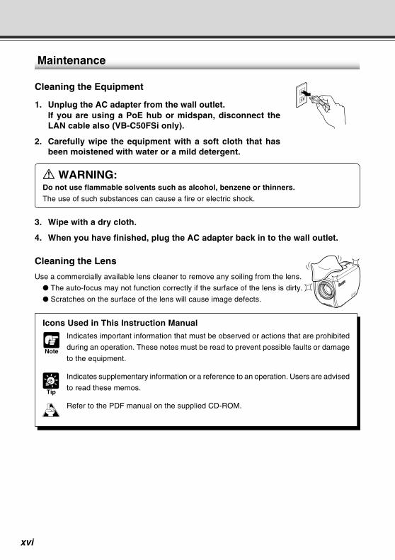
Cleaning the Equipment
1. Unplug the AC adapter from the wall outlet.If you are using a PoE hub or midspan, disconnect theLAN cable also (VB-C50FSi only).
2. Carefully wipe the equipment with a soft cloth that hasbeen moistened with water or a mild detergent.
a WARNING:Do not use flammable solvents such as alcohol, benzene or thinners.
The use of such substances can cause a fire or electric shock.
3. Wipe with a dry cloth.
4. When you have finished, plug the AC adapter back in to the wall outlet.
Cleaning the Lens
Use a commercially available lens cleaner to remove any soiling from the lens.
The auto-focus may not function correctly if the surface of the lens is dirty.
Scratches on the surface of the lens will cause image defects.
Icons Used in This Instruction Manual
Note
Indicates important information that must be observed or actions that are prohibited
during an operation. These notes must be read to prevent possible faults or damage
to the equipment.
Tip
Indicates supplementary information or a reference to an operation. Users are advised
to read these memos.
Refer to the PDF manual on the supplied CD-ROM.d
COPY
Before Using the
VB-C50FSi/VB-C50FiThis chapter describes the features of the VB-C50FSi/VB-
C50Fi, the hardware and software requirements, and the
name and functions of the system components.
Chapter
COPY
1-2
The VB-C50FSi/VB-C50Fi is a system that distributes live videos via the Internet or an intranet. It
can be used in a wide range of applications, such as distributing live videos from a Web site or
monitoring. The system is configured for the VB-C50FSi/VB-C50Fi and viewer software. Please
use the supplied viewer software for viewing videos distributed by the VB-C50FSi/VB-C50Fi and
controlling cameras (→ P.1-4, 2-14).
Broadband Video Distribution function
The VB-C50FSi/VB-C50Fi is capable of capturing videos at up to 30 fps (NTSC)/25 fps (PAL).
Motion-JPEG type is used to compress video images. For networking, auto-negotiation between
Ethernet 100Base-TX/10Base-T is provided and a leased line or ADSL can also be used through
a router. Since video quality and the frame rate can be freely set, videos can be distributed under
conditions that best suit the network bandwidth.* Please refer to P.1-10 to confirm whether your VB-C50FSi/VB-C50Fi is PAL model or NTSC model.
Concurrent video is distributed up to 50 clients
Up to 50 clients can view video at the same time from a single VB-C50FSi/VB-C50Fi.
High-performance 26x zoom camera and video distribution server functionshoused in a single unit
The camera capable of full zoom function (high-performance 26x zoom) and its server functions
for distributing videos through a network are compactly housed in a single unit. By simply connecting
a LAN cable and a power supply, the unit can distribute live videos from any location* where it is
installed.* The unit cannot be installed in locations subject to direct sunlight, high temperatures, high humidity, or
other adverse conditions (→ P.xiii, xiv).
Can be mounted on ceilings, etc.
The VB-C50FSi/VB-C50Fi can be installed on the ceiling or a wall using a mounting arm*.* The unit cannot be installed in locations subject to direct sunlight, high temperatures, high humidity, or
other adverse conditions (→ P.xiii, xiv).
Built-in PoE (Power over Ethernet) function (VB-C50FSi)
By using an IEEE 802.3af-compliant PoE hub or midspan, power can be supplied to the VB-
C50FSi via a LAN cable. This simplifies the installation process since there is no need to fit power
outlets at each camera location.* Use only approved PoE hubs or midspans. (→ P.2-6)* The LAN cable used to connect the VB-C50FSi to a PoE hub or midspan should be no more than 100
meters long.
Remote camera control from the viewer
The VB-C50FSi/VB-C50Fi comes with two types of viewer software: the Viewer for PC and the
Viewer for Java. The viewers give you full remote control of the camera zoom magnification of the
VB-C50FSi/VB-C50Fi, allowing you to view videos with plenty of ambiance.
Shade Correction function
If the background of an image is bright, making the subject difficult to see, you can adjust the
contrast of the darker areas to make it easier to see. Unlike backlight compensation, the shade
correction feature allows image processing without adversely affecting the existing lighter regions.
Features of the VB-C50FSi/VB-C50Fi
COPY

1-3
Before U
sing the VB
-C50FS
i/VB
-C50Fi
Features of the VB-C50FSi/VB-C50Fi
Zoom Position Preset function
If often-used camera zoom positions and related items are saved in advance as presets, the
camera can be controlled from the viewer by simply selecting a desired preset. Up to 10 presets
can be stored.
View Restriction function
You can set restrictions on camera zoom magnifications. For example, if the VB-C50FSi/VB-
C50Fi is showing camera footage on the Internet, it is possible to distribute videos while protecting
privacy (→ P.iii, “Request concerning disclosure of live videos and audio”).
More powerful security functions
The destinations for video distributions can be restricted based on passwords. Up to 50 clients
can be registered.
Using preset schedules or links with external devices to record pictures oraudio*Using the Multi-Terminal Module (→ P.1-11), you can set picture and audio recording* based on
ON/OFF input from an external device and from previously-set schedules. If VBCollector is used,
images and sound recorded* by the VB-C50FSi/VB-C50Fi can be automatically collected so that
you can view the images and play back the audio data* on a PC.
* Audio recording and Audio Playback functions are only available on the VB-C50FSi.
* Only available with a particular model of the VB-C50FSi (→ P.iii)
Audio Playback (VB-C50FSi)Using the Multi-Terminal Module (→ P.1-11), you can connect a speaker with amp to the camera.
Then, you can register your favorite audio files or sample files recorded on a CD-ROM and play
the registered files based on ON/OFF input from an external device and from previously-set
schedules.
Audio transmission (VB-C50FSi)Using the Multi-Terminal Module (→ P.1-11), you can connect a microphone* and speaker with
amp to the camera and then send and receive audio* via the Viewer.
* Only available with a particular model of the VB-C50FSi (→ P.iii)
Night mode shooting
By canceling the infrared cut filter, you can increase the camera’s sensitivity and take pictures
even in very dimly lit situations.
Motion detection function
You can perform external device control, video and audio recording* by detecting changes in the
image caused by motion of people or objects.
* Only available with a particular model of the VB-C50FSi (→ P.iii)
Service settings with schedule function
You can start up motion detection and external device services by setting up a visual and easy-
to-understand schedule in the calendar.
COPY
1-4
Hardware and Software Requirements
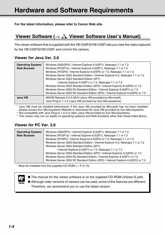
Viewer Software (→ d Viewer Software User’s Manual)
The viewer software that is supplied with the VB-C50FSi/VB-C50Fi lets you view the video captured
by the VB-C50FSi/VB-C50Fi and control the camera.
For the latest information, please refer to Canon Web site.
Note
The manual for the viewer software is on the supplied CD-ROM (Viewer-E.pdf).
Although older versions of viewers can be used, some of the features are different.
Therefore, we recommend you to use the latest version.
Viewer for PC Ver. 3.6
Operating System/ Windows 2000(SP4) / Internet Explorer 6.0(SP1), Netscape 7.1 or 7.2Web Browser Windows XP(SP1a) / Internet Explorer 6.0(SP1), Netscape 7.1 or 7.2
Windows XP(SP2) / Internet Explorer 6.0(SP2) or 7.0, Netscape 7.1 or 7.2Windows Server 2003 Standard Edition / Internet Explorer 6.0, Netscape 7.1 or 7.2Windows Server 2003 Standard Edition (SP1)
/ Internet Explorer 6.0(SP1) or 7.0, Netscape 7.1 or 7.2Windows Server 2003 Standard Edition (SP2) / Internet Explorer 6.0(SP2) or 7.0Windows Server 2003 R2 Standard Edition / Internet Explorer 6.0(SP1) or 7.0Windows Server 2003 R2 Standard Edition (SP2) / Internet Explorer 6.0(SP2) or 7.0
* Must be installed from the supplied CD-ROM (→ P.2-13).
Viewer for Java Ver. 3.6
Operating System/ Windows 2000(SP4) / Internet Explorer 6.0(SP1), Netscape 7.1 or 7.2Web Browser Windows XP(SP1a) / Internet Explorer 6.0(SP1), Netscape 7.1 or 7.2
Windows XP(SP2) / Internet Explorer 6.0(SP2) or 7.0, Netscape 7.1 or 7.2Windows Server 2003 Standard Edition / Internet Explorer 6.0, Netscape 7.1 or 7.2Windows Server 2003 Standard Edition (SP1)
/ Internet Explorer 6.0(SP1) or 7.0, Netscape 7.1 or 7.2Windows Server 2003 Standard Edition (SP2) / Internet Explorer 6.0(SP2) or 7.0Windows Server 2003 R2 Standard Edition / Internet Explorer 6.0(SP1) or 7.0Windows Server 2003 R2 Standard Edition (SP2) / Internet Explorer 6.0(SP2) or 7.0
Java VM MSVM Release 5.0.0.3810 (Java VM provided by Microsoft)Java Plug-in 1.4.2 (Java VM provided by Sun Microsystems)
* Java VM must be installed beforehand. If the Java VM provided by Microsoft has not been installed,please access Sun Microsystems Website to download the Java VM provided by Sun Microsystems.
* Not compatible with Java Plug-in 1.5.0 or later (Java VM provided by Sun Microsystems).* This viewer may not run stably on operating systems and Web browsers other than those listed above.
COPY
1-5
Before U
sing the VB
-C50FS
i/VB
-C50Fi
Hardware and Software Requirements
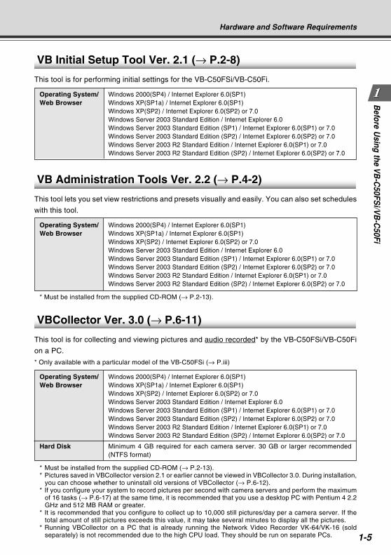
VBCollector Ver. 3.0 (→ P.6-11)
This tool is for collecting and viewing pictures and audio recorded* by the VB-C50FSi/VB-C50Fi
on a PC.
* Only available with a particular model of the VB-C50FSi (→ P.iii)
Operating System/ Windows 2000(SP4) / Internet Explorer 6.0(SP1)Web Browser Windows XP(SP1a) / Internet Explorer 6.0(SP1)
Windows XP(SP2) / Internet Explorer 6.0(SP2) or 7.0Windows Server 2003 Standard Edition / Internet Explorer 6.0Windows Server 2003 Standard Edition (SP1) / Internet Explorer 6.0(SP1) or 7.0Windows Server 2003 Standard Edition (SP2) / Internet Explorer 6.0(SP2) or 7.0Windows Server 2003 R2 Standard Edition / Internet Explorer 6.0(SP1) or 7.0Windows Server 2003 R2 Standard Edition (SP2) / Internet Explorer 6.0(SP2) or 7.0
Hard Disk Minimum 4 GB required for each camera server. 30 GB or larger recommended(NTFS format)
* Must be installed from the supplied CD-ROM (→ P.2-13).* Pictures saved in VBCollector version 2.1 or earlier cannot be viewed in VBCollector 3.0. During installation,
you can choose whether to uninstall old versions of VBCollector (→ P.6-12).* If you configure your system to record pictures per second with camera servers and perform the maximum
of 16 tasks (→ P.6-17) at the same time, it is recommended that you use a desktop PC with Pentium 4 2.2GHz and 512 MB RAM or greater.
* It is recommended that you configure to collect up to 10,000 still pictures/day per a camera server. If thetotal amount of still pictures exceeds this value, it may take several minutes to display all the pictures.
* Running VBCollector on a PC that is already running the Network Video Recorder VK-64/VK-16 (soldseparately) is not recommended due to the high CPU load. They should be run on separate PCs.
VB Initial Setup Tool Ver. 2.1 (→ P.2-8)
This tool is for performing initial settings for the VB-C50FSi/VB-C50Fi.
Operating System/ Windows 2000(SP4) / Internet Explorer 6.0(SP1)Web Browser Windows XP(SP1a) / Internet Explorer 6.0(SP1)
Windows XP(SP2) / Internet Explorer 6.0(SP2) or 7.0Windows Server 2003 Standard Edition / Internet Explorer 6.0Windows Server 2003 Standard Edition (SP1) / Internet Explorer 6.0(SP1) or 7.0Windows Server 2003 Standard Edition (SP2) / Internet Explorer 6.0(SP2) or 7.0Windows Server 2003 R2 Standard Edition / Internet Explorer 6.0(SP1) or 7.0Windows Server 2003 R2 Standard Edition (SP2) / Internet Explorer 6.0(SP2) or 7.0
VB Administration Tools Ver. 2.2 (→ P.4-2)
This tool lets you set view restrictions and presets visually and easily. You can also set schedules
with this tool.
Operating System/ Windows 2000(SP4) / Internet Explorer 6.0(SP1)Web Browser Windows XP(SP1a) / Internet Explorer 6.0(SP1)
Windows XP(SP2) / Internet Explorer 6.0(SP2) or 7.0Windows Server 2003 Standard Edition / Internet Explorer 6.0Windows Server 2003 Standard Edition (SP1) / Internet Explorer 6.0(SP1) or 7.0Windows Server 2003 Standard Edition (SP2) / Internet Explorer 6.0(SP2) or 7.0Windows Server 2003 R2 Standard Edition / Internet Explorer 6.0(SP1) or 7.0Windows Server 2003 R2 Standard Edition (SP2) / Internet Explorer 6.0(SP2) or 7.0
* Must be installed from the supplied CD-ROM (→ P.2-13).
COPY
1-6
Note
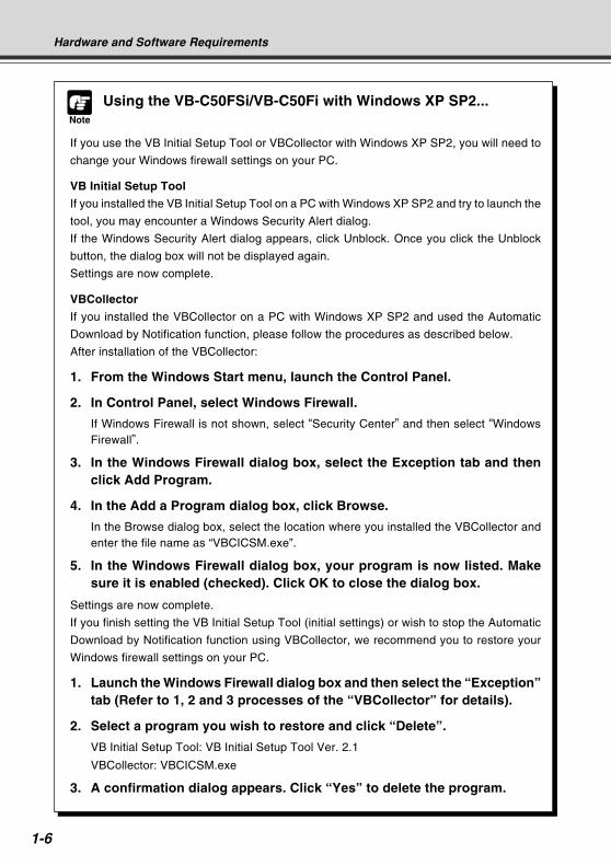
Using the VB-C50FSi/VB-C50Fi with Windows XP SP2...
If you use the VB Initial Setup Tool or VBCollector with Windows XP SP2, you will need to
change your Windows firewall settings on your PC.
VB Initial Setup Tool
If you installed the VB Initial Setup Tool on a PC with Windows XP SP2 and try to launch the
tool, you may encounter a Windows Security Alert dialog.
If the Windows Security Alert dialog appears, click Unblock. Once you click the Unblock
button, the dialog box will not be displayed again.
Settings are now complete.
VBCollector
If you installed the VBCollector on a PC with Windows XP SP2 and used the Automatic
Download by Notification function, please follow the procedures as described below.
After installation of the VBCollector:
1. From the Windows Start menu, launch the Control Panel.
2. In Control Panel, select Windows Firewall.
If Windows Firewall is not shown, select “Security Center” and then select “WindowsFirewall”.
3. In the Windows Firewall dialog box, select the Exception tab and thenclick Add Program.
4. In the Add a Program dialog box, click Browse.
In the Browse dialog box, select the location where you installed the VBCollector andenter the file name as “VBCICSM.exe”.
5. In the Windows Firewall dialog box, your program is now listed. Makesure it is enabled (checked). Click OK to close the dialog box.
Settings are now complete.
If you finish setting the VB Initial Setup Tool (initial settings) or wish to stop the Automatic
Download by Notification function using VBCollector, we recommend you to restore your
Windows firewall settings on your PC.
1. Launch the Windows Firewall dialog box and then select the “Exception”tab (Refer to 1, 2 and 3 processes of the “VBCollector” for details).
2. Select a program you wish to restore and click “Delete”.
VB Initial Setup Tool: VB Initial Setup Tool Ver. 2.1
VBCollector: VBCICSM.exe
3. A confirmation dialog appears. Click “Yes” to delete the program.
Hardware and Software Requirements
COPY
1-7
Before U
sing the VB
-C50FS
i/VB
-C50Fi
Hardware and Software Requirements
Note
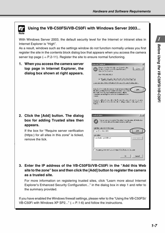
Using the VB-C50FSi/VB-C50Fi with Windows Server 2003...
With Windows Server 2003, the default security level for the Internet or intranet sites inInternet Explorer is “High”.As a result, windows such as the settings window do not function normally unless you firstregister the site in the contents block dialog box that appears when you access the camera
server top page (→ P.2-11). Register the site to ensure normal functioning.
1. When you access the camera servertop page in Internet Explorer, thedialog box shown at right appears.
2. Click the [Add] button. The dialogbox for adding Trusted sites thenappears.
If the box for “Require server verification(https:) for all sites in this zone” is ticked,remove the tick.
3. Enter the IP address of the VB-C50FSi/VB-C50Fi in the “Add this Website to the zone” box and then click the [Add] button to register the cameraas a trusted site.
For more information on registering trusted sites, click “Learn more about InternetExplorer’s Enhanced Security Configuration...” in the dialog box in step 1 and refer tothe summary provided.
If you have enabled the Windows firewall settings, please refer to the “Using the VB-C50FSi/VB-C50Fi with Windows XP SP2...” (→ P.1-6) and follow the instructions.
COPY
1-8
Hardware and Software Requirements
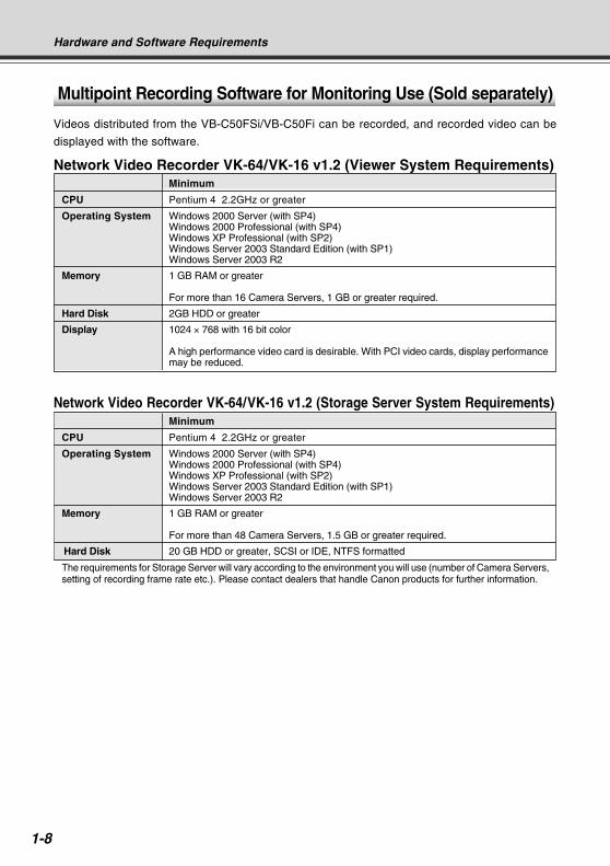
Multipoint Recording Software for Monitoring Use (Sold separately)
Videos distributed from the VB-C50FSi/VB-C50Fi can be recorded, and recorded video can be
displayed with the software.
Network Video Recorder VK-64/VK-16 v1.2 (Viewer System Requirements)Minimum
CPU Pentium 4 2.2GHz or greater
Operating System Windows 2000 Server (with SP4)Windows 2000 Professional (with SP4)Windows XP Professional (with SP2)Windows Server 2003 Standard Edition (with SP1)Windows Server 2003 R2
Memory 1 GB RAM or greater
For more than 16 Camera Servers, 1 GB or greater required.
Hard Disk 2GB HDD or greater
Display 1024 × 768 with 16 bit color
A high performance video card is desirable. With PCI video cards, display performancemay be reduced.
Network Video Recorder VK-64/VK-16 v1.2 (Storage Server System Requirements)Minimum
CPU Pentium 4 2.2GHz or greater
Operating System Windows 2000 Server (with SP4)Windows 2000 Professional (with SP4)Windows XP Professional (with SP2)Windows Server 2003 Standard Edition (with SP1)Windows Server 2003 R2
Memory 1 GB RAM or greater
For more than 48 Camera Servers, 1.5 GB or greater required.
Hard Disk 20 GB HDD or greater, SCSI or IDE, NTFS formatted
The requirements for Storage Server will vary according to the environment you will use (number of Camera Servers,setting of recording frame rate etc.). Please contact dealers that handle Canon products for further information.CO
PY
1-9
Before U
sing the VB
-C50FS
i/VB
-C50Fi
System Components and Their Operation
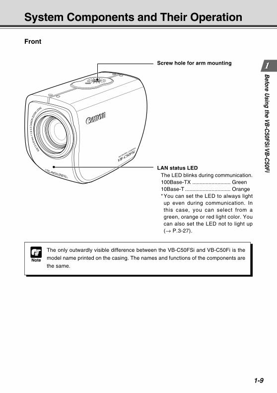
Front
LAN status LEDThe LED blinks during communication.100Base-TX .......................... Green10Base-T ............................... Orange* You can set the LED to always lightup even during communication. Inthis case, you can select from agreen, orange or red light color. Youcan also set the LED not to light up(→ P.3-27).
Screw hole for arm mounting
Note
The only outwardly visible difference between the VB-C50FSi and VB-C50Fi is the
model name printed on the casing. The names and functions of the components are
the same.COPY
1-10
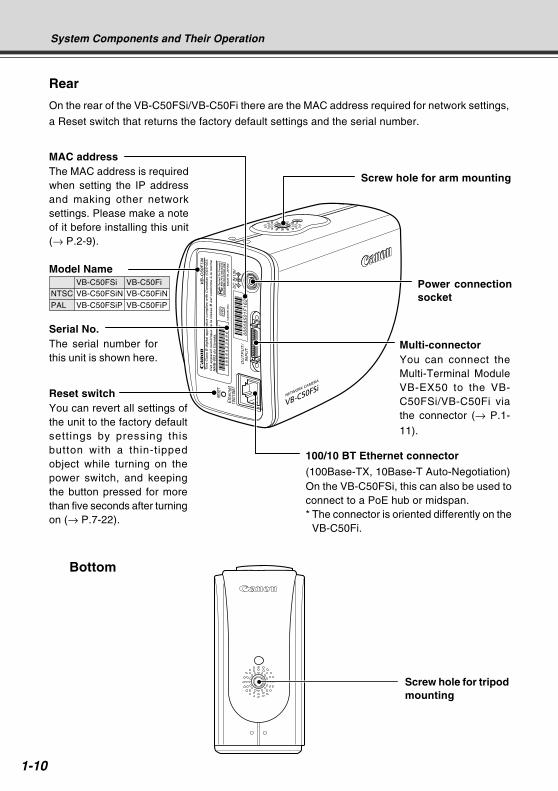
MAC addressThe MAC address is requiredwhen setting the IP addressand making other networksettings. Please make a noteof it before installing this unit(→ P.2-9).
Reset switchYou can revert all settings ofthe unit to the factory defaultsettings by pressing thisbutton with a thin-tippedobject while turning on thepower switch, and keepingthe button pressed for morethan five seconds after turningon (→ P.7-22).
Serial No.The serial number forthis unit is shown here.
System Components and Their Operation
00
00
85
01
F1
62
Rear
On the rear of the VB-C50FSi/VB-C50Fi there are the MAC address required for network settings,
a Reset switch that returns the factory default settings and the serial number.
Power connectionsocket
Multi-connectorYou can connect theMulti-Terminal ModuleVB-EX50 to the VB-C50FSi/VB-C50Fi viathe connector (→ P.1-11).
100/10 BT Ethernet connector
(100Base-TX, 10Base-T Auto-Negotiation)On the VB-C50FSi, this can also be used toconnect to a PoE hub or midspan.* The connector is oriented differently on the
VB-C50Fi.
Screw hole for tripodmounting
Bottom
Screw hole for arm mounting
Model NameVB-C50FSi VB-C50Fi
NTSC VB-C50FSiN VB-C50FiN
PAL VB-C50FSiP VB-C50FiP
COPY
1-11
Before U
sing the VB
-C50FS
i/VB
-C50Fi
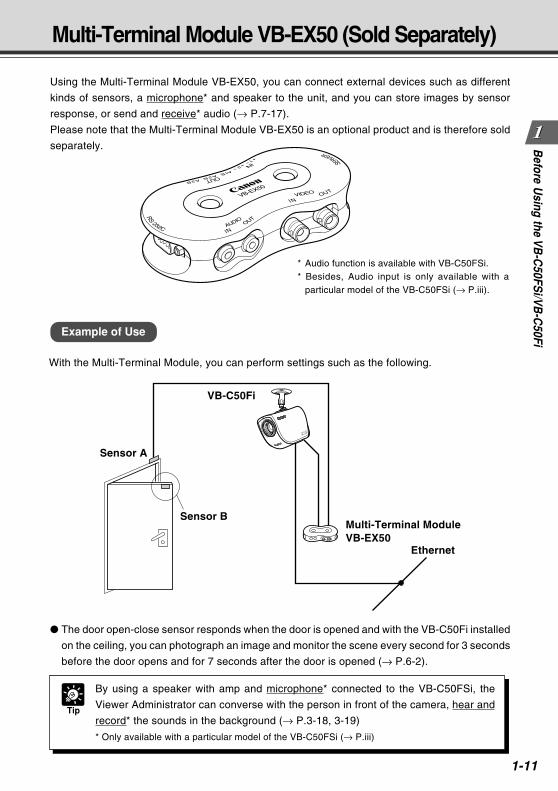
Using the Multi-Terminal Module VB-EX50, you can connect external devices such as different
kinds of sensors, a microphone* and speaker to the unit, and you can store images by sensor
response, or send and receive* audio (→ P.7-17).
Please note that the Multi-Terminal Module VB-EX50 is an optional product and is therefore sold
separately.
Multi-Terminal Module VB-EX50 (Sold Separately)
Example of Use
With the Multi-Terminal Module, you can perform settings such as the following.
The door open-close sensor responds when the door is opened and with the VB-C50Fi installed
on the ceiling, you can photograph an image and monitor the scene every second for 3 seconds
before the door opens and for 7 seconds after the door is opened (→ P.6-2).
* Audio function is available with VB-C50FSi.* Besides, Audio input is only available with a
particular model of the VB-C50FSi (→ P.iii).
Tip
By using a speaker with amp and microphone* connected to the VB-C50FSi, the
Viewer Administrator can converse with the person in front of the camera, hear and
record* the sounds in the background (→ P.3-18, 3-19)
* Only available with a particular model of the VB-C50FSi (→ P.iii)
Sensor A
VB-C50Fi
Multi-Terminal ModuleVB-EX50
Ethernet
Sensor BCOPY

1-12
COPY
Setting UpThis chapter explains how to set up the VB-C50FSi/VB-C50Fi,
run initial checks, and confirm that the camera’s images are
displayed correctly.
Chapter
COPY
2-2
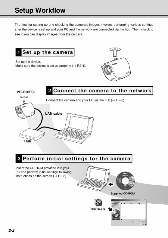
Set up the camera1
Perform init ial sett ings for the camera3
Connect the camera to the network2
LAN cable
VB-C50FSi
Hub
Set up the device.Make sure the device is set up properly (→ P.2-4).
Connect the camera and your PC via the hub (→ P.2-6).
Insert the CD-ROM provided into your PC and perform initial settings following instructions on the screen (→ P.2-8).
Supplied CD-ROM
Setup Workflow
The flow for setting up and checking the camera’s images involves performing various settings
after the device is set up and your PC and the network are connected via the hub. Then, check to
see if you can display images from the camera.
COPY
2-3
Settin
g U
pSetup Workflow
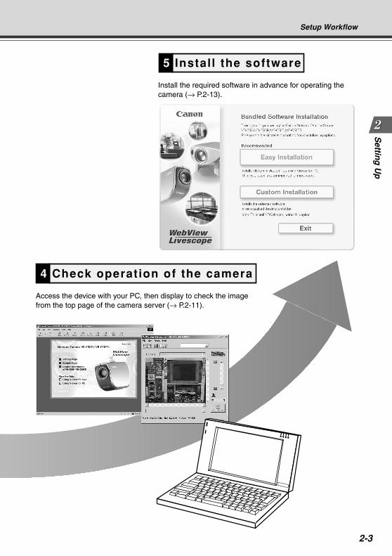
Instal l the software5
Check operation of the camera4
Access the device with your PC, then display to check the image from the top page of the camera server (→ P.2-11).
Install the required software in advance for operating the camera (→ P.2-13).
COPY
2-4
1. Set Up the Camera
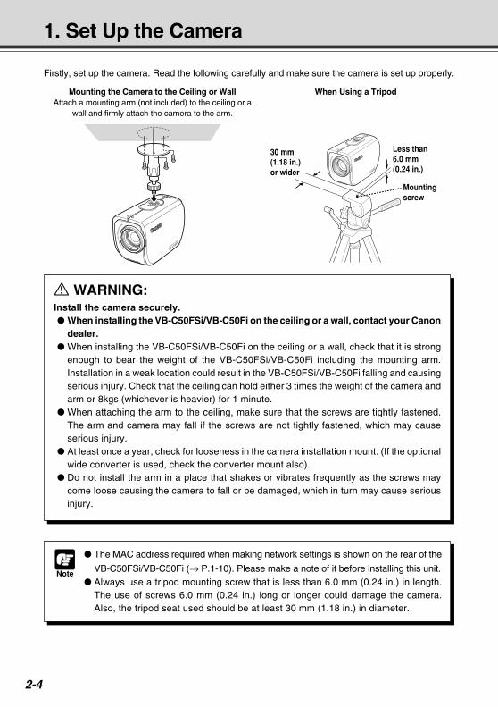
a WARNING:Install the camera securely. When installing the VB-C50FSi/VB-C50Fi on the ceiling or a wall, contact your Canon
dealer. When installing the VB-C50FSi/VB-C50Fi on the ceiling or a wall, check that it is strong
enough to bear the weight of the VB-C50FSi/VB-C50Fi including the mounting arm.Installation in a weak location could result in the VB-C50FSi/VB-C50Fi falling and causingserious injury. Check that the ceiling can hold either 3 times the weight of the camera andarm or 8kgs (whichever is heavier) for 1 minute.
When attaching the arm to the ceiling, make sure that the screws are tightly fastened.The arm and camera may fall if the screws are not tightly fastened, which may causeserious injury.
At least once a year, check for looseness in the camera installation mount. (If the optionalwide converter is used, check the converter mount also).
Do not install the arm in a place that shakes or vibrates frequently as the screws maycome loose causing the camera to fall or be damaged, which in turn may cause seriousinjury.
Note
The MAC address required when making network settings is shown on the rear of the
VB-C50FSi/VB-C50Fi (→ P.1-10). Please make a note of it before installing this unit. Always use a tripod mounting screw that is less than 6.0 mm (0.24 in.) in length.
The use of screws 6.0 mm (0.24 in.) long or longer could damage the camera.Also, the tripod seat used should be at least 30 mm (1.18 in.) in diameter.
Firstly, set up the camera. Read the following carefully and make sure the camera is set up properly.
Mounting screw
Less than 6.0 mm (0.24 in.)
30 mm (1.18 in.) or wider
Mounting the Camera to the Ceiling or WallAttach a mounting arm (not included) to the ceiling or a
wall and firmly attach the camera to the arm.
When Using a Tripod
COPY
2-5
Settin
g U
p1. Set Up the Camera
Note
The camera may not operate correctly if a wide converter other than the WL-37
is used.
Be sure to install the VB-C50FSi/VB-C50Fi firmly because the weight of the camera
increases when the optional Wide Converter WL-37 is attached.
If you use the optional Wide Converter WL-37, set the zoom lens to the wide-angle
end. If you set the zoom lens to the telephoto end, the image resolution will be
affected and the auto focus might have problems.
Using the Wide Converter
The optional Wide Converter WL-37 can be used to provide wide-angle shots (approx. 0.74× the
normal focal distance).
Mount the wide converter correctly so that it is level and fitted securely onto the camera. When
mounted correctly, the wide converter should turn roughly 3 times before stopping.
Setup is now complete.
Wide Converter
COPY
2-6
2. Connect the Camera to the Network
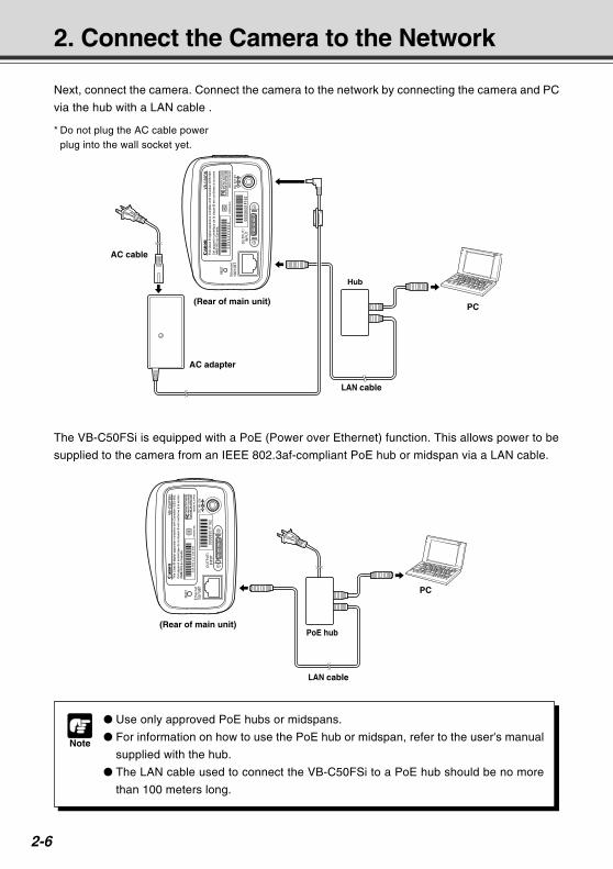
Next, connect the camera. Connect the camera to the network by connecting the camera and PC
via the hub with a LAN cable .
* Do not plug the AC cable powerplug into the wall socket yet.
PC
Hub
LAN cable
AC cable
AC adapter
(Rear of main unit)
0000
8501
F162
Note
Use only approved PoE hubs or midspans.
For information on how to use the PoE hub or midspan, refer to the user's manual
supplied with the hub.
The LAN cable used to connect the VB-C50FSi to a PoE hub should be no more
than 100 meters long.
The VB-C50FSi is equipped with a PoE (Power over Ethernet) function. This allows power to be
supplied to the camera from an IEEE 802.3af-compliant PoE hub or midspan via a LAN cable.
PC
LAN cable
PoE hub(Rear of main unit)
0000
8501
F162COPY
2-7
Settin
g U
p
Turning the Power ON and OFF
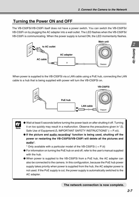
The VB-C50FSi/VB-C50Fi itself does not have a power switch. You can switch the VB-C50FSi/
VB-C50Fi on by plugging the AC adapter into a wall outlet. The LED flashes when the VB-C50FSi/
VB-C50Fi is communicating. When the power supply is turned ON, the LED momentarily flashes.
Note
Wait at least 5 seconds before turning the power back on after shutting it off. Turning
it on too quickly may result in a malfunction. Observe the precautions given in “a
Safe Use of Equipment/a IMPORTANT SAFETY INSTRUCTIONS” (→ P.xii).
If the picture and audio recording* function is being used, shutting off the
power or restarting the VB-C50FSi/VB-C50Fi will delete all the pictures and
audio*.
* Only available with a particular model of the VB-C50FSi (→ P.iii)
For information on turning the PoE hub on and off, refer to the user's manual supplied
with the hub.
When power is supplied to the VB-C50FSi from a PoE hub, the AC adapter can
also be connected to the camera. In this configuration, because the PoE hub power
supply takes priority when power is supplied from the hub, the AC adapter power is
not used. If the PoE supply is cut, the power supply is automatically switched to the
AC adapter.
The network connection is now complete.
AC cable
to AC outlet
AC adapter
Main unit
PoE hub
LAN cable
VB-C50FSi
When power is supplied to the VB-C50FSi via a LAN cable using a PoE hub, connecting the LAN
cable to a hub that is being supplied with power will turn the VB-C50FSi on.
2. Connect the Camera to the Network
COPY
2-8
Once your PC and the camera are connected, perform the initial settings next. The instructions
here follow on from “2. Connect the Camera to the Network”, where one camera is connected to
a PC as an example.
3. Perform Initial Settings for the Camera
Note
Do not turn on the camera at this stage.
If you are using a PoE hub or midspan with the VB-C50FSi, do not connect the
LAN cable.
Continued on the following page. a
Supplied CD-ROM
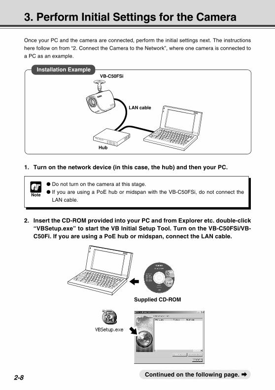
1. Turn on the network device (in this case, the hub) and then your PC.
2. Insert the CD-ROM provided into your PC and from Explorer etc. double-click“VBSetup.exe” to start the VB Initial Setup Tool. Turn on the VB-C50FSi/VB-C50Fi. If you are using a PoE hub or midspan, connect the LAN cable.
LAN cable
VB-C50FSi
Hub
Installation Example
COPY
2-9
Settin
g U
p
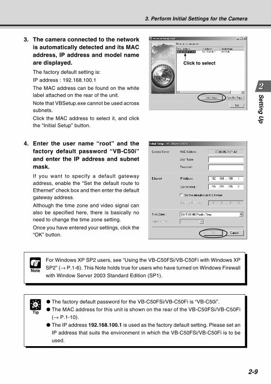
3. The camera connected to the networkis automatically detected and its MACaddress, IP address and model nameare displayed.
The factory default setting is:
IP address : 192.168.100.1
The MAC address can be found on the whitelabel attached on the rear of the unit.
Note that VBSetup.exe cannot be used acrosssubnets.
Click the MAC address to select it, and clickthe “Initial Setup” button.
4. Enter the user name “root” and thefactory default password “VB-C50i”and enter the IP address and subnetmask.
If you want to specify a default gatewayaddress, enable the “Set the default route toEthernet” check box and then enter the defaultgateway address.
Although the time zone and video signal canalso be specified here, there is basically noneed to change the time zone setting.
Once you have entered your settings, click the“OK” button.
Click to select
Tip
The factory default password for the VB-C50FSi/VB-C50Fi is “VB-C50i”.
The MAC address for this unit is shown on the rear of the VB-C50FSi/VB-C50Fi
(→ P.1-10).
The IP address 192.168.100.1 is used as the factory default setting. Please set an
IP address that suits the environment in which the VB-C50FSi/VB-C50Fi is to be
used.
3. Perform Initial Settings for the Camera
Note
For Windows XP SP2 users, see “Using the VB-C50FSi/VB-C50Fi with Windows XP
SP2” (→ P.1-6). This Note holds true for users who have turned on Windows Firewall
with Window Server 2003 Standard Edition (SP1).
COPY
2-10
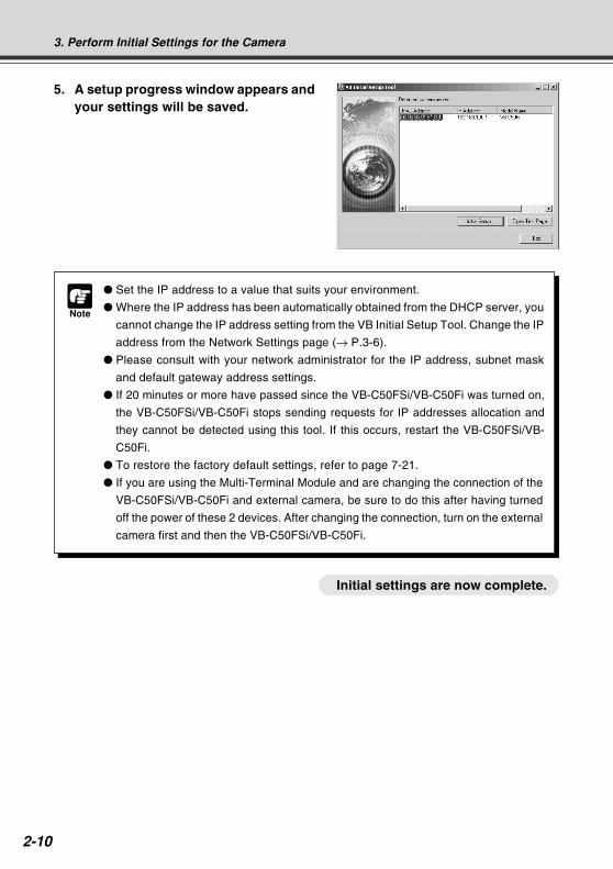
5. A setup progress window appears andyour settings will be saved.
Note
Set the IP address to a value that suits your environment.
Where the IP address has been automatically obtained from the DHCP server, you
cannot change the IP address setting from the VB Initial Setup Tool. Change the IP
address from the Network Settings page (→ P.3-6).
Please consult with your network administrator for the IP address, subnet mask
and default gateway address settings.
If 20 minutes or more have passed since the VB-C50FSi/VB-C50Fi was turned on,
the VB-C50FSi/VB-C50Fi stops sending requests for IP addresses allocation and
they cannot be detected using this tool. If this occurs, restart the VB-C50FSi/VB-
C50Fi.
To restore the factory default settings, refer to page 7-21.
If you are using the Multi-Terminal Module and are changing the connection of the
VB-C50FSi/VB-C50Fi and external camera, be sure to do this after having turned
off the power of these 2 devices. After changing the connection, turn on the external
camera first and then the VB-C50FSi/VB-C50Fi.
3. Perform Initial Settings for the Camera
Initial settings are now complete.COPY
2-11
Settin
g U
p
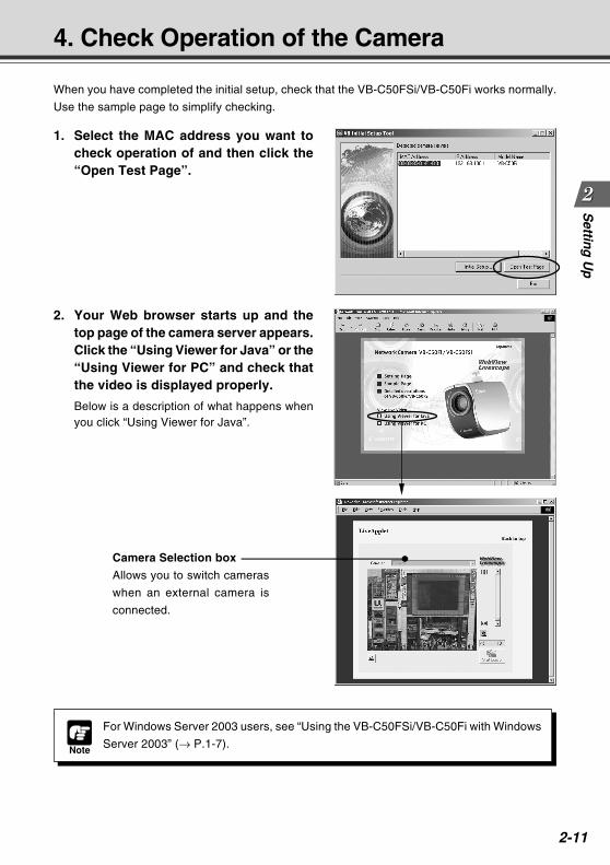
2. Your Web browser starts up and thetop page of the camera server appears.Click the “Using Viewer for Java” or the“Using Viewer for PC” and check thatthe video is displayed properly.
Below is a description of what happens whenyou click “Using Viewer for Java”.
When you have completed the initial setup, check that the VB-C50FSi/VB-C50Fi works normally.
Use the sample page to simplify checking.
4. Check Operation of the Camera
1. Select the MAC address you want tocheck operation of and then click the“Open Test Page”.
Camera Selection box
Allows you to switch cameras
when an external camera is
connected.
Note
For Windows Server 2003 users, see “Using the VB-C50FSi/VB-C50Fi with Windows
Server 2003” (→ P.1-7).
COPY
2-12
4. Check Operation of the Camera
Tip
To use the Viewer for Java, you need to install Java VM beforehand. See Canon
Web site for more details.
To use the Viewer for PC, you must install the Viewer for PC beforehand (→ P.2-13).
Check of operation is now complete.
COPY
2-13
Settin
g U
p5. Install the Software
You must install software to display images from the camera and to manage the camera. There
are 3 types of software you can install.
• VB Administration Tools: Software for managing the camera (→ P.4-2).
• Viewer for PC: Software for displaying images from the camera (→ P.2-14).
• VBCollector: Software that allows you to collect pictures and audio recorded* by the camera on
a PC and view the recorded images and play back the audio data* on the PC (→ P.6-11). When
using older versions of VBCollector, please refer to page 6-12.
* Only available with a particular model of the VB-C50FSi (→ P.iii)
1. Check that all other applications are closed, insert the CD-ROM included withthe camera into the CD-ROM drive of your PC and follow the steps below.
1 Double-click [My Computer] on the desktop.
If you are using Windows XP, click the [Start] button and then [My Computer].
2 Double-click the CD-ROM icon displayed and then double-click the [VBTools] folder.
3 Double-click [VBToolsInstall.exe] to start the installation.
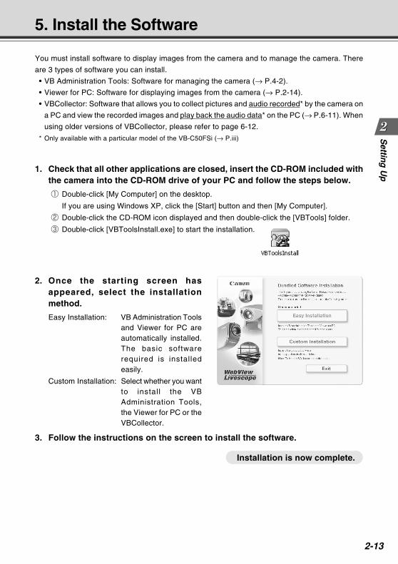
2. Once the starting screen hasappeared, select the installationmethod.
Easy Installation: VB Administration Toolsand Viewer for PC areautomatically installed.The basic softwarerequired is installedeasily.
Custom Installation: Select whether you wantto install the VBAdministration Tools,the Viewer for PC or theVBCollector.
3. Follow the instructions on the screen to install the software.
Installation is now complete.
COPY
2-14
Viewer Software Overview
By using the Viewer software, you can view images sent from the VB-C50FSi/VB-C50Fi on a PC, as
well as control the camera. Below is an outline of the Viewer software. For details, please refer to
“Viewer Overview” (→ P.5-4) or to the Viewer Software User’s Manual (Viewer-E.pdf) on the CD-ROM.
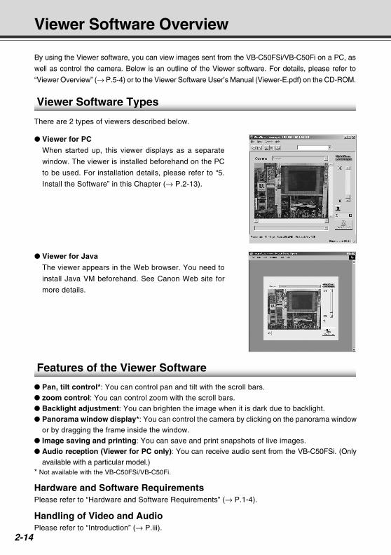
Viewer for PC
When started up, this viewer displays as a separate
window. The viewer is installed beforehand on the PC
to be used. For installation details, please refer to “5.
Install the Software” in this Chapter (→ P.2-13).
Viewer Software Types
There are 2 types of viewers described below.
Viewer for Java
The viewer appears in the Web browser. You need to
install Java VM beforehand. See Canon Web site for
more details.
Features of the Viewer Software
Pan, tilt control*: You can control pan and tilt with the scroll bars. zoom control: You can control zoom with the scroll bars. Backlight adjustment: You can brighten the image when it is dark due to backlight. Panorama window display*: You can control the camera by clicking on the panorama window
or by dragging the frame inside the window. Image saving and printing: You can save and print snapshots of live images. Audio reception (Viewer for PC only): You can receive audio sent from the VB-C50FSi. (Only
available with a particular model.)* Not available with the VB-C50FSi/VB-C50Fi.
Hardware and Software RequirementsPlease refer to “Hardware and Software Requirements” (→ P.1-4).
Handling of Video and AudioPlease refer to “Introduction” (→ P.iii).
COPY
Basic SettingsThis chapter describes the basic settings for the VB-C50FSi/
VB-C50Fi such as network connection, camera control, date
and time setting and mail. Be sure to perform these settings
after setting up.
* The VB Administration Tools (→ P.4-2) described in
Chapter 4 provide a convenient way to set view restrictions
as well as presets.
Chapter
COPY
3-2
What Can I Do on Each of the Settings Pages?
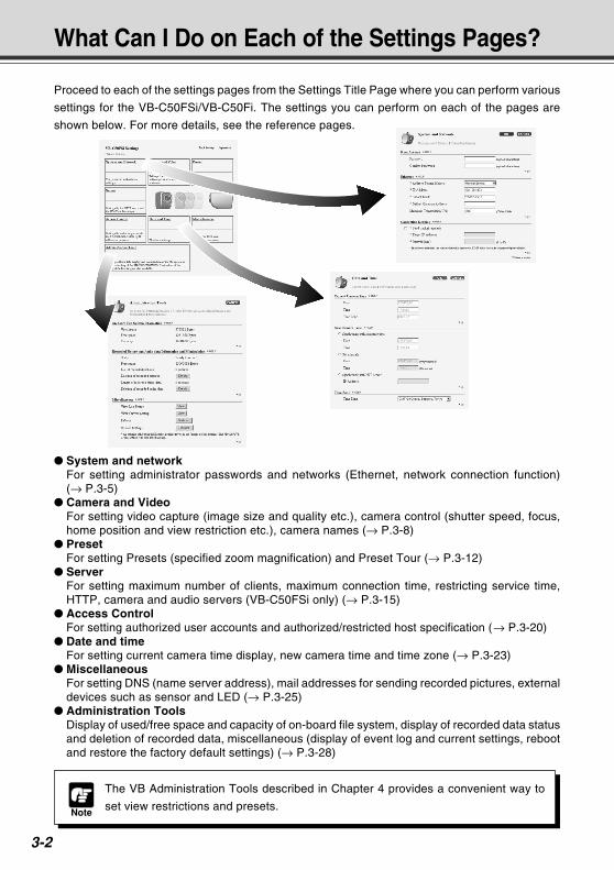
Proceed to each of the settings pages from the Settings Title Page where you can perform various
settings for the VB-C50FSi/VB-C50Fi. The settings you can perform on each of the pages are
shown below. For more details, see the reference pages.
Note
The VB Administration Tools described in Chapter 4 provides a convenient way to
set view restrictions and presets.
System and networkFor setting administrator passwords and networks (Ethernet, network connection function)(→ P.3-5)
Camera and VideoFor setting video capture (image size and quality etc.), camera control (shutter speed, focus,home position and view restriction etc.), camera names (→ P.3-8)
PresetFor setting Presets (specified zoom magnification) and Preset Tour (→ P.3-12)
ServerFor setting maximum number of clients, maximum connection time, restricting service time,HTTP, camera and audio servers (VB-C50FSi only) (→ P.3-15)
Access ControlFor setting authorized user accounts and authorized/restricted host specification (→ P.3-20)
Date and timeFor setting current camera time display, new camera time and time zone (→ P.3-23)
MiscellaneousFor setting DNS (name server address), mail addresses for sending recorded pictures, externaldevices such as sensor and LED (→ P.3-25)
Administration ToolsDisplay of used/free space and capacity of on-board file system, display of recorded data statusand deletion of recorded data, miscellaneous (display of event log and current settings, rebootand restore the factory default settings) (→ P.3-28)
COPY
3-3
Basic S
etting
sAccessing the Settings Title Page
Note
This manual uses the IP address 192.168.100.1 (the factory default setting) below as
an example to describe the detail settings. Please enter the actual IP address that is
set in your VB-C50FSi/VB-C50Fi.
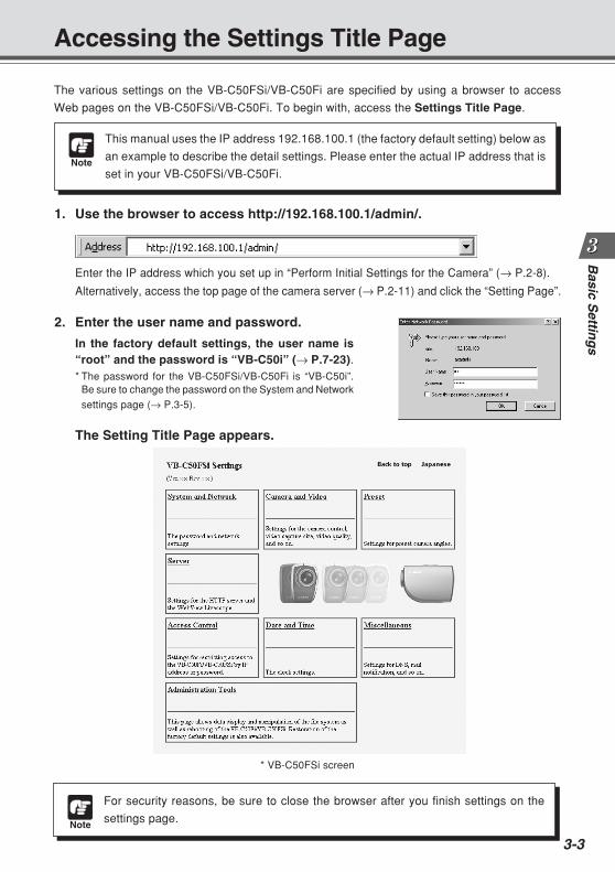
The various settings on the VB-C50FSi/VB-C50Fi are specified by using a browser to access
Web pages on the VB-C50FSi/VB-C50Fi. To begin with, access the Settings Title Page.
1. Use the browser to access http://192.168.100.1/admin/.
Enter the IP address which you set up in “Perform Initial Settings for the Camera” (→ P.2-8).
Alternatively, access the top page of the camera server (→ P.2-11) and click the “Setting Page”.
2. Enter the user name and password.
In the factory default settings, the user name is“root” and the password is “VB-C50i” (→ P.7-23).* The password for the VB-C50FSi/VB-C50Fi is “VB-C50i”.
Be sure to change the password on the System and Network
settings page (→ P.3-5).
The Setting Title Page appears.
* VB-C50FSi screen
Note
For security reasons, be sure to close the browser after you finish settings on the
settings page.
COPY
3-4
Settings Title Page
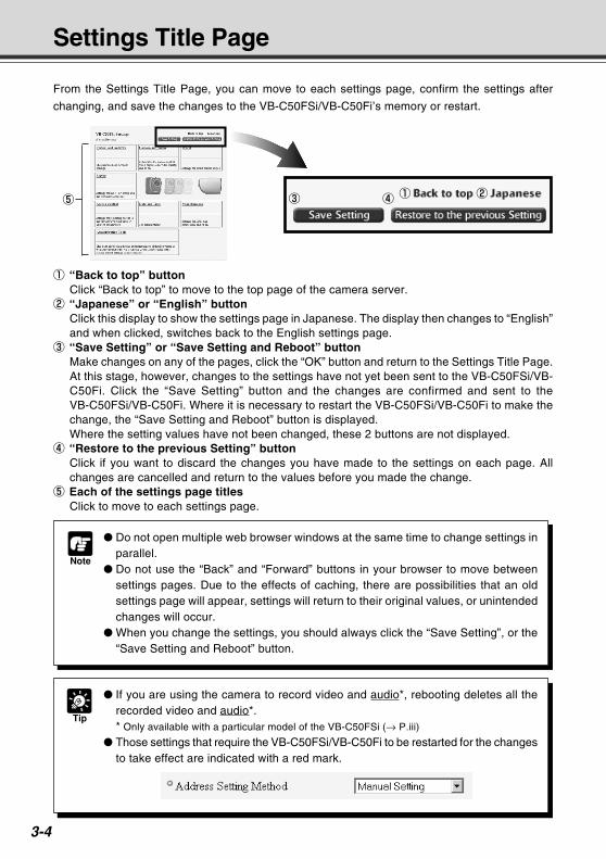
From the Settings Title Page, you can move to each settings page, confirm the settings after
changing, and save the changes to the VB-C50FSi/VB-C50Fi’s memory or restart.
5
1 “Back to top” buttonClick “Back to top” to move to the top page of the camera server.
2 “Japanese” or “English” buttonClick this display to show the settings page in Japanese. The display then changes to “English”and when clicked, switches back to the English settings page.
3 “Save Setting” or “Save Setting and Reboot” buttonMake changes on any of the pages, click the “OK” button and return to the Settings Title Page.At this stage, however, changes to the settings have not yet been sent to the VB-C50FSi/VB-C50Fi. Click the “Save Setting” button and the changes are confirmed and sent to theVB-C50FSi/VB-C50Fi. Where it is necessary to restart the VB-C50FSi/VB-C50Fi to make thechange, the “Save Setting and Reboot” button is displayed.Where the setting values have not been changed, these 2 buttons are not displayed.
4 “Restore to the previous Setting” buttonClick if you want to discard the changes you have made to the settings on each page. Allchanges are cancelled and return to the values before you made the change.
5 Each of the settings page titlesClick to move to each settings page.
Note
Do not open multiple web browser windows at the same time to change settings inparallel.
Do not use the “Back” and “Forward” buttons in your browser to move betweensettings pages. Due to the effects of caching, there are possibilities that an oldsettings page will appear, settings will return to their original values, or unintendedchanges will occur.
When you change the settings, you should always click the “Save Setting”, or the“Save Setting and Reboot” button.
Tip
If you are using the camera to record video and audio*, rebooting deletes all therecorded video and audio*.* Only available with a particular model of the VB-C50FSi (→ P.iii)
Those settings that require the VB-C50FSi/VB-C50Fi to be restarted for the changesto take effect are indicated with a red mark.
1 23 4
COPY
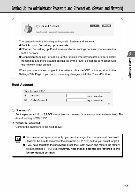
3-5
Basic S
etting
s
You can perform the following settings with System and Network.
Root Account: For setting up passwords.
Ethernet: For setting up IP addresses and other settings necessary for connection
to the network.
Connection Keeping: For setting up the function whereby packets are periodically
transmitted and there is automatic dial-up by the router so that the connection with
the network is not broken.
When you have made changes to the settings, click the “OK” button to return to the
Settings Title Page. If you do not make any changes, click the “Cancel” button.
Setting Up the Administrator Password and Ethernet etc. (System and Network)
Root Account
1
2
Note
For reasons of system security, you must change the root account password.
However, be sure to remember the password (→ P.7-23) so that you do not forget it.
If you have forgotten the password, press the Reset switch and restore the factory
default settings (→ P.7-22). However, note that all settings are restored to the
factory default settings.
1 “Password”
Set the password. Up to 8 ASCII characters can be used (spaces or printable characters). The
default setting is “VB-C50i”.
2 “Confirm Password”
Confirm the password in the field above.COPY
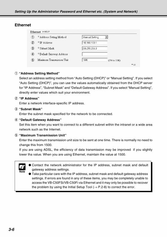
3-6
Ethernet
1
2
Note
Contact the network administrator for the IP address, subnet mask and defaultgateway address settings.
Take particular care with the IP address, subnet mask and default gateway addresssettings. If errors are found in any of these items, you may be completely unable toaccess the VB-C50FSi/VB-C50Fi via Ethernet and it may only be possible to recoverthe problem by using the Initial Setup Tool (→ P.2-8) to correct the error.
3
4
5
Setting Up the Administrator Password and Ethernet etc. (System and Network)
1 “Address Setting Method”
Select an address setting method from “Auto Setting (DHCP)” or “Manual Setting”. If you select
“Auto Setting (DHCP)”, you can use the values automatically obtained from the DHCP server
for “IP Address”, “Subnet Mask” and “Default Gateway Address”. If you select “Manual Setting”,
directly enter values which suit your environment.
2 “IP Address”
Enter a network interface-specific IP address.
3 “Subnet Mask”
Enter the subnet mask specified for the network to be connected.
4 “Default Gateway Address”
Set this item when you want to connect to a different subnet within the intranet or a wide area
network such as the Internet.
5 “Maximum Transmission Unit”
Enter the maximum transmission unit size to be sent at one time. There is normally no need to
change this from 1500.
If you are using ADSL, the efficiency of data transmission may be improved if you slightly
lower tha value. When you are using Ethernet, maintain the value at 1500.COPY
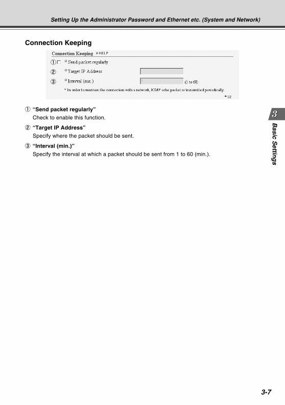
3-7
Basic S
etting
s
Connection Keeping
1
2
3
Setting Up the Administrator Password and Ethernet etc. (System and Network)
1 “Send packet regularly”
Check to enable this function.
2 “Target IP Address”
Specify where the packet should be sent.
3 “Interval (min.)”
Specify the interval at which a packet should be sent from 1 to 60 (min.).
COPY
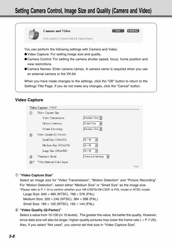
3-8
You can perform the following settings with Camera and Video.
Video Capture: For setting image size and quality.
Camera Control: For setting the camera shutter speed, focus, home position and
view restrictions.
Camera Names: Enter camera names. A camera name is required when you use
an external camera or the VK-64.
When you have made changes to the settings, click the “OK” button to return to the
Settings Title Page. If you do not make any changes, click the “Cancel” button.
Setting Camera Control, Image Size and Quality (Camera and Video)
Video Capture
1
2
3
4
1 “Video Capture Size”
Select an image size for “Video Transmission”, “Motion Detection” and “Picture Recording”.
For “Motion Detection”, select either “Medium Size” or “Small Size” as the image size.*Please refer to P.1-10 to confirm whether your VB-C50FSi/VB-C50Fi is PAL model or NTSC model.
Large Size: 640 × 480 (NTSC), 768 × 576 (PAL)
Medium Size: 320 × 240 (NTSC), 384 × 288 (PAL)
Small Size: 160 × 120 (NTSC), 192 × 144 (PAL)
2 “Video Quality (Q-Factor)”
Select a value from 10-100 (in 10 levels) . The greater the value, the better the quality. However,
since data size will also be larger, higher-quality pictures may lower the frame rate (→ P.7-25).
Also, if you select “Not used”, you cannot set that size in “Video Capture Size”.
COPY
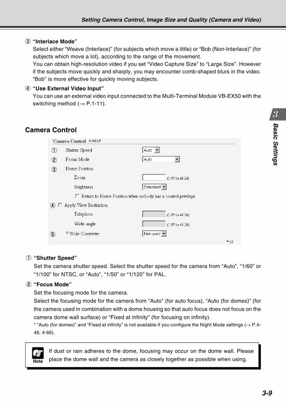
3-9
Basic S
etting
s
Camera Control
1
2
3
4
Setting Camera Control, Image Size and Quality (Camera and Video)
5
3 “Interlace Mode”Select either “Weave (Interlace)” (for subjects which move a little) or “Bob (Non-Interlace)” (forsubjects which move a lot), according to the range of the movement.You can obtain high-resolution video if you set “Video Capture Size” to “Large Size”. Howeverif the subjects move quickly and sharply, you may encounter comb-shaped blurs in the video.“Bob” is more effective for quickly moving subjects.
4 “Use External Video Input”You can use an external video input connected to the Multi-Terminal Module VB-EX50 with theswitching method (→ P.1-11).
1 “Shutter Speed”
Set the camera shutter speed. Select the shutter speed for the camera from “Auto”, “1/60” or
“1/100” for NTSC, or “Auto”, “1/50” or “1/120” for PAL.
2 “Focus Mode”
Set the focusing mode for the camera.
Select the focusing mode for the camera from “Auto” (for auto focus), “Auto (for domes)” (for
the camera used in combination with a dome housing so that auto focus does not focus on the
camera dome wall surface) or “Fixed at infinity” (for focusing on infinity).* “Auto (for domes)” and “Fixed at infinity” is not available if you configure the Night Mode settings (→ P.4-
48, 4-66).
Note
If dust or rain adheres to the dome, focusing may occur on the dome wall. Please
place the dome wall and the camera as closely together as possible when using.
COPY
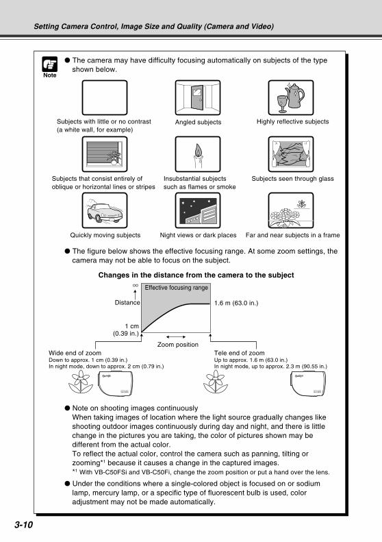
3-10
Setting Camera Control, Image Size and Quality (Camera and Video)
Note
The camera may have difficulty focusing automatically on subjects of the typeshown below.
The figure below shows the effective focusing range. At some zoom settings, thecamera may not be able to focus on the subject.
Changes in the distance from the camera to the subject
Subjects with little or no contrast(a white wall, for example)
Angled subjects Highly reflective subjects
Subjects that consist entirely ofoblique or horizontal lines or stripes
Insubstantial subjectssuch as flames or smoke
Subjects seen through glass
Quickly moving subjects Night views or dark places Far and near subjects in a frame
Distance
Effective focusing range
1.6 m (63.0 in.)
1 cm(0.39 in.)
Zoom positionTele end of zoomUp to approx. 1.6 m (63.0 in.)In night mode, up to approx. 2.3 m (90.55 in.)
Wide end of zoomDown to approx. 1 cm (0.39 in.)In night mode, down to approx. 2 cm (0.79 in.)
Note on shooting images continuouslyWhen taking images of location where the light source gradually changes likeshooting outdoor images continuously during day and night, and there is littlechange in the pictures you are taking, the color of pictures shown may bedifferent from the actual color.To reflect the actual color, control the camera such as panning, tilting orzooming*1 because it causes a change in the captured images.*1 With VB-C50FSi and VB-C50Fi, change the zoom position or put a hand over the lens.
Under the conditions where a single-colored object is focused on or sodiumlamp, mercury lamp, or a specific type of fluorescent bulb is used, coloradjustment may not be made automatically.
COPY
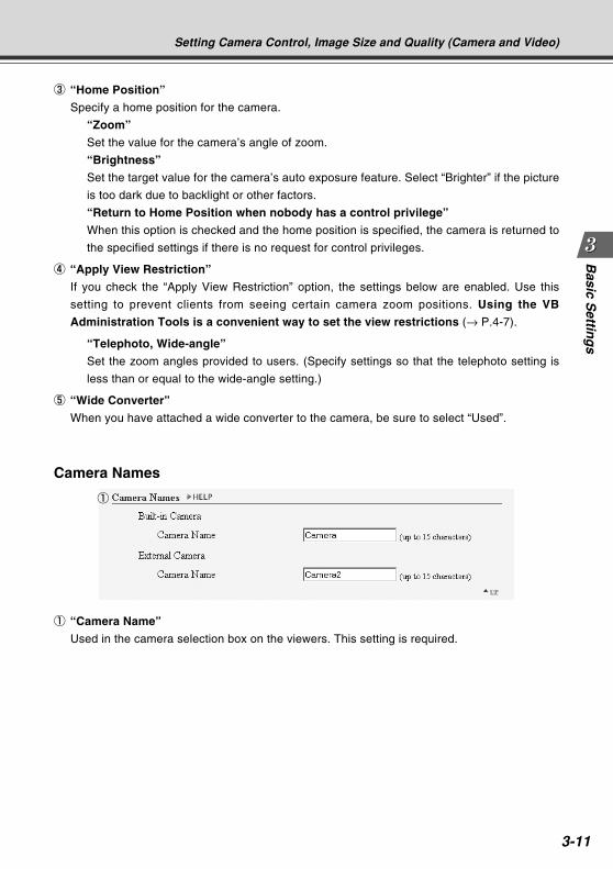
3-11
Basic S
etting
s
Camera Names
1 “Camera Name”
Used in the camera selection box on the viewers. This setting is required.
1
3 “Home Position”
Specify a home position for the camera.
“Zoom”
Set the value for the camera’s angle of zoom.
“Brightness”
Set the target value for the camera’s auto exposure feature. Select “Brighter” if the picture
is too dark due to backlight or other factors.
“Return to Home Position when nobody has a control privilege”
When this option is checked and the home position is specified, the camera is returned to
the specified settings if there is no request for control privileges.
4 “Apply View Restriction”
If you check the “Apply View Restriction” option, the settings below are enabled. Use this
setting to prevent clients from seeing certain camera zoom positions. Using the VB
Administration Tools is a convenient way to set the view restrictions (→ P.4-7).
“Telephoto, Wide-angle”
Set the zoom angles provided to users. (Specify settings so that the telephoto setting is
less than or equal to the wide-angle setting.)
5 “Wide Converter”
When you have attached a wide converter to the camera, be sure to select “Used”.
Setting Camera Control, Image Size and Quality (Camera and Video)
COPY
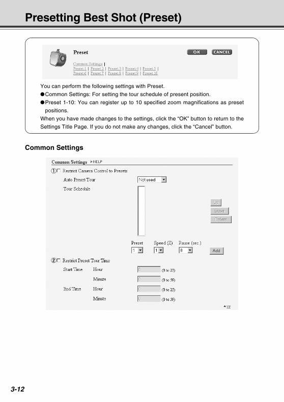
3-12
Presetting Best Shot (Preset)
You can perform the following settings with Preset.
Common Settings: For setting the tour schedule of present position.
Preset 1-10: You can register up to 10 specified zoom magnifications as preset
positions.
When you have made changes to the settings, click the “OK” button to return to the
Settings Title Page. If you do not make any changes, click the “Cancel” button.
Common Settings
1
2 COPY

3-13
Basic S
etting
s
Tip
Even if you have set Auto Preset Tour to “For Viewers” or “Always”, the Preset Tour
will not work while you are controlling the camera with the Viewer for PC or the Admin
Viewer etc.
If “Restrict Camera Control to Presets” is selected, the presets can be displayed
alone without displaying the camera control GUI on the Viewer for Java (→ P.5-13).
Presetting Best Shot (Preset)
1 “Restrict Camera Control to Presets”
Camera control by using the Viewer for PC and the Viewer for Java can be restricted to the
preset zoom positions specified in Preset 1-10.
“Auto Preset Tour”
Select a Preset Tour setting from the following options.
“Not used”
Preset Tour does not operate.
“For Viewers”
Operates if any of the Viewer for Java, Viewer for PC or Admin Viewer is connecting.
“Always”
Preset Tour always operates.
“Tour Schedule”
Select the Preset number you want to set up in the Tour Schedule from “Preset” below, and
after setting “Speed (Z)” and “Pause (sec.)”, click the “Add” button and the Presets are
listed. You can also set up the start time and end time of the Preset Tour.
“Up” button and “Down” button
Select a Preset in the list, click the “Up” or “Down” button to change the order of the Preset Tour.
“Delete” button
Delete the selected Preset.
“Preset”
Select the number of the Preset you want to set up.
“Speed (Z)”
Set up the camera speed when zooming. The larger the numeric value, the faster the camera
will move.
“Pause (sec.)”
Set the length of time the camera will pause in the Preset position, from 0-120 seconds in
units of five seconds.
“Add” button
Add the Preset you have set to the Tour Schedule.
2 “Restrict Preset Tour Time”
Select to set the start time and end time of the Tour Schedule.
COPY
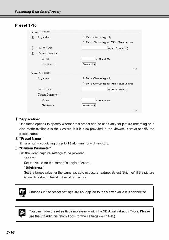
3-14
Tip
You can make preset settings more easily with the VB Administration Tools. Please
use the VB Administration Tools for the settings (→ P.4-13).
Preset 1-10
NoteChanges in the preset settings are not applied to the viewer while it is connected.
Presetting Best Shot (Preset)
1
3
2
1 “Application”
Use these options to specify whether this preset can be used only for picture recording or is
also made available in the viewers. If it is also provided in the viewers, always specify the
preset name.
2 “Preset Name”
Enter a name consisting of up to 15 alphanumeric characters.
3 “Camera Parameter”
Set the video capture settings to be provided.
“Zoom”
Set the value for the camera’s angle of zoom.
“Brightness”
Set the target value for the camera’s auto exposure feature. Select “Brighter” if the picture
is too dark due to backlight or other factors.
COPY
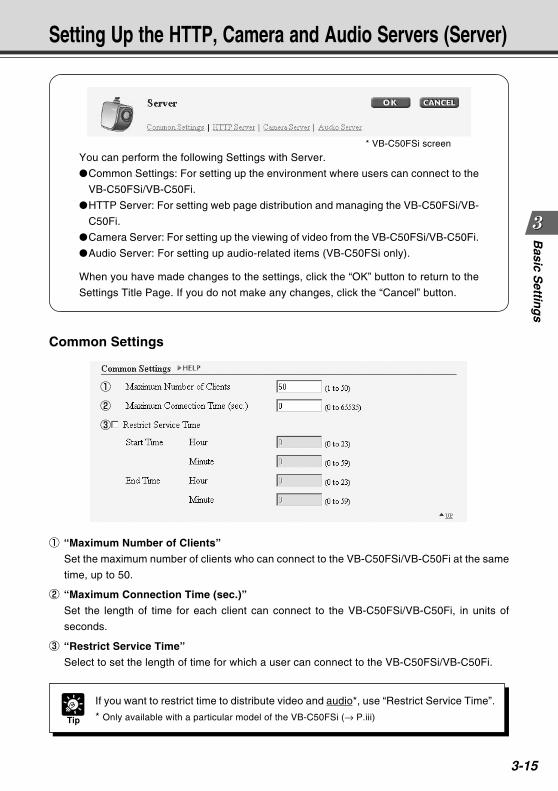
3-15
Basic S
etting
s
You can perform the following Settings with Server.
Common Settings: For setting up the environment where users can connect to the
VB-C50FSi/VB-C50Fi.
HTTP Server: For setting web page distribution and managing the VB-C50FSi/VB-
C50Fi.
Camera Server: For setting up the viewing of video from the VB-C50FSi/VB-C50Fi.
Audio Server: For setting up audio-related items (VB-C50FSi only).
When you have made changes to the settings, click the “OK” button to return to the
Settings Title Page. If you do not make any changes, click the “Cancel” button.
Setting Up the HTTP, Camera and Audio Servers (Server)
Common Settings
1
2
3
Tip
If you want to restrict time to distribute video and audio*, use “Restrict Service Time”.
* Only available with a particular model of the VB-C50FSi (→ P.iii)
1 “Maximum Number of Clients”
Set the maximum number of clients who can connect to the VB-C50FSi/VB-C50Fi at the same
time, up to 50.
2 “Maximum Connection Time (sec.)”
Set the length of time for each client can connect to the VB-C50FSi/VB-C50Fi, in units of
seconds.
3 “Restrict Service Time”
Select to set the length of time for which a user can connect to the VB-C50FSi/VB-C50Fi.
* VB-C50FSi screen
COPY
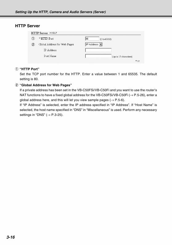
3-16
HTTP Server
1
2
Setting Up the HTTP, Camera and Audio Servers (Server)
1 “HTTP Port”
Set the TCP port number for the HTTP. Enter a value between 1 and 65535. The default
setting is 80.
2 “Global Address for Web Pages”
If a private address has been set in the VB-C50FSi/VB-C50Fi and you want to use the router’s
NAT functions to have a fixed global address for the VB-C50FSi/VB-C50Fi (→ P.5-26), enter a
global address here, and this will let you view sample pages (→ P.5-6).
If “IP Address” is selected, enter the IP address specified in “IP Address”. If “Host Name” is
selected, the host name specified in “DNS” in “Miscellaneous” is used. Perform any necessary
settings in “DNS” (→ P.3-25).
COPY
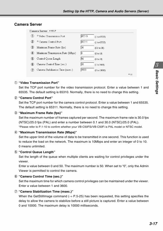
3-17
Basic S
etting
s
Camera Server
1
2
3
4
5
6
7
Setting Up the HTTP, Camera and Audio Servers (Server)
1 “Video Transmission Port”
Set the TCP port number for the video transmission protocol. Enter a value between 1 and
65535. The default setting is 65310. Normally, there is no need to change this setting.
2 “Camera Control Port”
Set the TCP port number for the camera control protocol. Enter a value between 1 and 65535.
The default setting is 65311. Normally, there is no need to change this setting.
3 “Maximum Frame Rate (fps)”
Set the maximum number of frames captured per second. The maximum frame rate is 30.0 fps
(NTSC)/25.0 fps (PAL) and enter a number between 0.1 and 30.0 (NTSC)/25.0 (PAL).*Please refer to P.1-10 to confirm whether your VB-C50FSi/VB-C50Fi is PAL model or NTSC model.
4 “Maximum Transmission Rate (Mbps)”
Set the upper limit of the volume of data to be transmitted in one second. This function is used
to reduce the load on the network. The maximum is 10Mbps and enter an integer of 0 to 10.
0 means unlimited.
5 “Control Queue Length”
Set the length of the queue when multiple clients are waiting for control privileges under the
viewer.
Enter a value between 0 and 50. The maximum number is 50. When set to “0”, only the Admin
Viewer is permitted to control the camera.
6 “Camera Control Time (sec.)”
Set the maximum time for which camera control privileges can be maintained under the viewer.
Enter a value between 1 and 3600.
7 “Camera Stabilization Time (msec.)”
When the GetStillImage command (→ P.5-25) has been requested, this setting specifies the
delay to allow the camera to stabilize before a still picture is captured. Enter a value between
0 and 10000. The maximum delay is 10000 milliseconds.
COPY
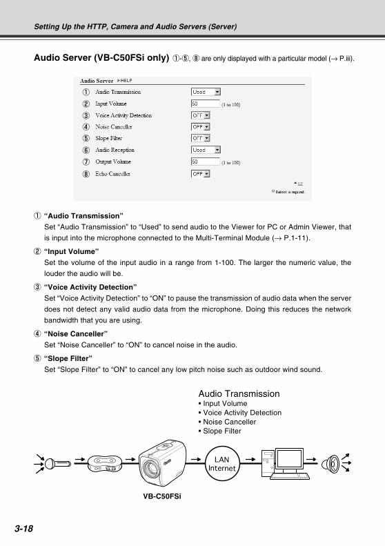
3-18
Setting Up the HTTP, Camera and Audio Servers (Server)
Audio Server (VB-C50FSi only)
1 “Audio Transmission”
Set “Audio Transmission” to “Used” to send audio to the Viewer for PC or Admin Viewer, that
is input into the microphone connected to the Multi-Terminal Module (→ P.1-11).
2 “Input Volume”
Set the volume of the input audio in a range from 1-100. The larger the numeric value, the
louder the audio will be.
3 “Voice Activity Detection”
Set “Voice Activity Detection” to “ON” to pause the transmission of audio data when the server
does not detect any valid audio data from the microphone. Doing this reduces the network
bandwidth that you are using.
4 “Noise Canceller”
Set “Noise Canceller” to “ON” to cancel noise in the audio.
5 “Slope Filter”
Set “Slope Filter” to “ON” to cancel any low pitch noise such as outdoor wind sound.
1
2
3
4
5
6
7
8
Audio Transmission• Input Volume• Voice Activity Detection• Noise Canceller• Slope Filter
VB-C50FSi
1-5, 8 are only displayed with a particular model (→ P.iii).
COPY
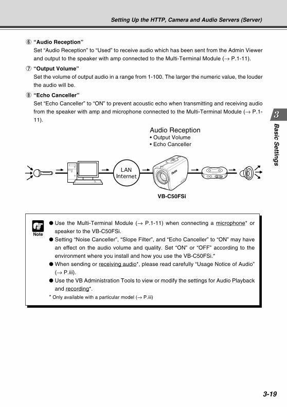
3-19
Basic S
etting
sSetting Up the HTTP, Camera and Audio Servers (Server)
Audio Reception• Output Volume• Echo Canceller
Note
Use the Multi-Terminal Module (→ P.1-11) when connecting a microphone* or
speaker to the VB-C50FSi.
Setting “Noise Canceller”, “Slope Filter”, and “Echo Canceller” to “ON” may have
an effect on the audio volume and quality. Set “ON” or “OFF” according to the
environment where you install and how you use the VB-C50FSi.*
When sending or receiving audio*, please read carefully “Usage Notice of Audio”
(→ P.iii).
Use the VB Administration Tools to view or modify the settings for Audio Playback
and recording*.
* Only available with a particular model (→ P.iii)
6 “Audio Reception”
Set “Audio Reception” to “Used” to receive audio which has been sent from the Admin Viewer
and output to the speaker with amp connected to the Multi-Terminal Module (→ P.1-11).
7 “Output Volume”
Set the volume of output audio in a range from 1-100. The larger the numeric value, the louder
the audio will be.
8 “Echo Canceller”
Set “Echo Canceller” to “ON” to prevent acoustic echo when transmitting and receiving audio
from the speaker with amp and microphone connected to the Multi-Terminal Module (→ P.1-
11).
VB-C50FSi
COPY
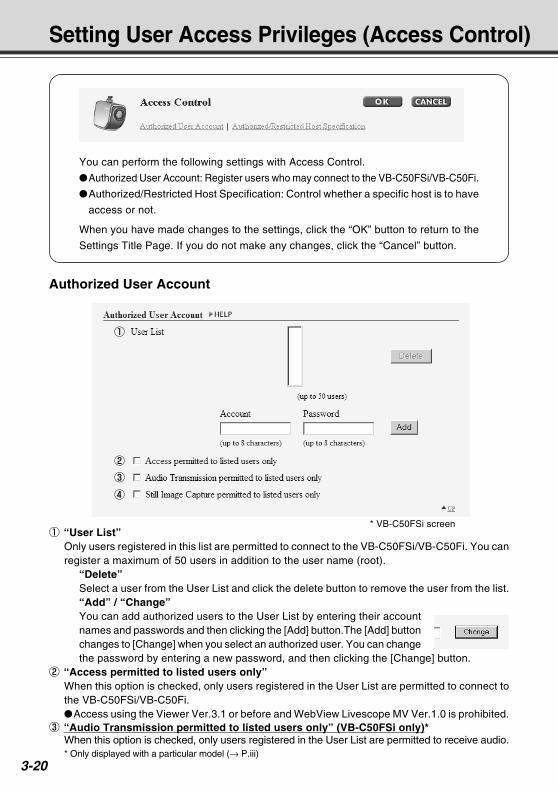
3-20
Setting User Access Privileges (Access Control)
You can perform the following settings with Access Control.
Authorized User Account: Register users who may connect to the VB-C50FSi/VB-C50Fi.
Authorized/Restricted Host Specification: Control whether a specific host is to have
access or not.
When you have made changes to the settings, click the “OK” button to return to the
Settings Title Page. If you do not make any changes, click the “Cancel” button.
Authorized User Account
1 “User List”Only users registered in this list are permitted to connect to the VB-C50FSi/VB-C50Fi. You canregister a maximum of 50 users in addition to the user name (root).
“Delete”Select a user from the User List and click the delete button to remove the user from the list.“Add” / “Change”You can add authorized users to the User List by entering their accountnames and passwords and then clicking the [Add] button.The [Add] buttonchanges to [Change] when you select an authorized user. You can changethe password by entering a new password, and then clicking the [Change] button.
2 “Access permitted to listed users only”When this option is checked, only users registered in the User List are permitted to connect tothe VB-C50FSi/VB-C50Fi.Access using the Viewer Ver.3.1 or before and WebView Livescope MV Ver.1.0 is prohibited.
3 “Audio Transmission permitted to listed users only” (VB-C50FSi only)*When this option is checked, only users registered in the User List are permitted to receive audio.* Only displayed with a particular model (→ P.iii)
1
2
3
4
* VB-C50FSi screenCOPY
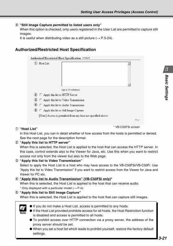
3-21
Basic S
etting
s
Authorized/Restricted Host Specification
Note
If you do not make a Host List, access is permitted to any hosts. If the Host List provided prohibits access for all hosts, the Host Restriction function
is disabled and access is permitted to all hosts. To prohibit access over HTTP connection via a proxy server, the address of the
proxy server should be set. When you set a host list which leads to prohibit yourself, restore the factory default
settings.
Setting User Access Privileges (Access Control)
1 “Host List”In this Host List, you can in detail whether of how access from the hosts is permitted or denied.See the next page for the description format.
2 “Apply this list to HTTP server”When this is selected, the Host List is applied to the host that can access the HTTP server. Inthis case, control extends also to the Viewer for Java, etc. Use this when you want to restrictaccess not only from the viewer but also to the Web page.
3 “Apply this list to Video Transmission”Select to apply the Host List to a host who may have access to the VB-C50FSi/VB-C50Fi. Use“Apply this list to Video Transmission” if you want to restrict access from the Viewer for Java andViewer for PC etc.
4 “Apply this list to Audio Transmission” (VB-C50FSi only)*When this is selected, the Host List is applied to the host that can receive audio.* Only displayed with a particular model (→ P.iii)
5 “Apply this list to Still Image Capture”When this is selected, the Host List is applied to the host that can capture still images.
1
2
3
4
4 “Still Image Capture permitted to listed users only”When this option is checked, only users registered in the User List are permitted to capture stillimages.It is useful when distributing video as a still picture (→ P.5-24).
5
* VB-C50FSi screen
COPY
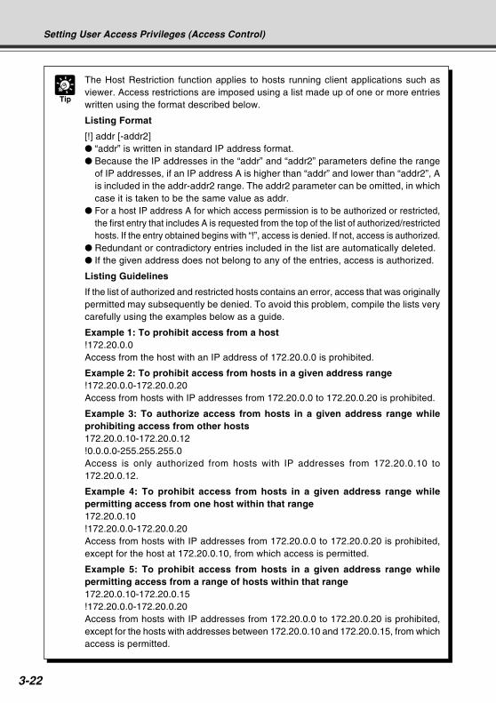
3-22
Tip
The Host Restriction function applies to hosts running client applications such asviewer. Access restrictions are imposed using a list made up of one or more entrieswritten using the format described below.
Listing Format
[!] addr [-addr2] “addr” is written in standard IP address format. Because the IP addresses in the “addr” and “addr2” parameters define the range
of IP addresses, if an IP address A is higher than “addr” and lower than “addr2”, Ais included in the addr-addr2 range. The addr2 parameter can be omitted, in whichcase it is taken to be the same value as addr.
For a host IP address A for which access permission is to be authorized or restricted,the first entry that includes A is requested from the top of the list of authorized/restrictedhosts. If the entry obtained begins with “!”, access is denied. If not, access is authorized.
Redundant or contradictory entries included in the list are automatically deleted. If the given address does not belong to any of the entries, access is authorized.
Listing Guidelines
If the list of authorized and restricted hosts contains an error, access that was originallypermitted may subsequently be denied. To avoid this problem, compile the lists verycarefully using the examples below as a guide.
Example 1: To prohibit access from a host!172.20.0.0Access from the host with an IP address of 172.20.0.0 is prohibited.
Example 2: To prohibit access from hosts in a given address range!172.20.0.0-172.20.0.20Access from hosts with IP addresses from 172.20.0.0 to 172.20.0.20 is prohibited.
Example 3: To authorize access from hosts in a given address range whileprohibiting access from other hosts172.20.0.10-172.20.0.12!0.0.0.0-255.255.255.0Access is only authorized from hosts with IP addresses from 172.20.0.10 to172.20.0.12.
Example 4: To prohibit access from hosts in a given address range whilepermitting access from one host within that range172.20.0.10!172.20.0.0-172.20.0.20Access from hosts with IP addresses from 172.20.0.0 to 172.20.0.20 is prohibited,except for the host at 172.20.0.10, from which access is permitted.
Example 5: To prohibit access from hosts in a given address range whilepermitting access from a range of hosts within that range172.20.0.10-172.20.0.15!172.20.0.0-172.20.0.20Access from hosts with IP addresses from 172.20.0.0 to 172.20.0.20 is prohibited,except for the hosts with addresses between 172.20.0.10 and 172.20.0.15, from whichaccess is permitted.
Setting User Access Privileges (Access Control)
COPY
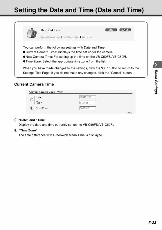
3-23
Basic S
etting
sSetting the Date and Time (Date and Time)
You can perform the following settings with Date and Time.
Current Camera Time: Displays the time set up for the camera.
New Camera Time: For setting up the time on the VB-C50FSi/VB-C50Fi.
Time Zone: Select the appropriate time zone from the list.
When you have made changes to the settings, click the “OK” button to return to the
Settings Title Page. If you do not make any changes, click the “Cancel” button.
Current Camera Time
1
2
1 “Date” and “Time”
Display the date and time currently set on the VB-C50FSi/VB-C50Fi.
2 “Time Zone”
The time difference with Greenwich Mean Time is displayed.COPY
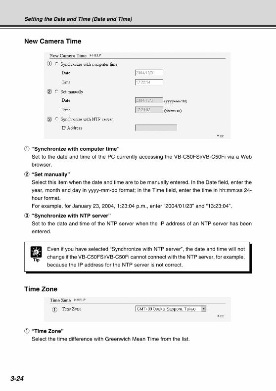
3-24
New Camera Time
1
2
3
Time Zone
1
Tip
Even if you have selected “Synchronize with NTP server”, the date and time will not
change if the VB-C50FSi/VB-C50Fi cannot connect with the NTP server, for example,
because the IP address for the NTP server is not correct.
Setting the Date and Time (Date and Time)
1 “Synchronize with computer time”
Set to the date and time of the PC currently accessing the VB-C50FSi/VB-C50Fi via a Web
browser.
2 “Set manually”
Select this item when the date and time are to be manually entered. In the Date field, enter the
year, month and day in yyyy-mm-dd format; in the Time field, enter the time in hh:mm:ss 24-
hour format.
For example, for January 23, 2004, 1:23:04 p.m., enter “2004/01/23” and “13:23:04”.
3 “Synchronize with NTP server”
Set to the date and time of the NTP server when the IP address of an NTP server has been
entered.
1 “Time Zone”
Select the time difference with Greenwich Mean Time from the list.
COPY
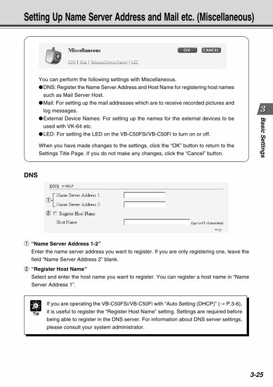
3-25
Basic S
etting
s
You can perform the following settings with Miscellaneous.
DNS: Register the Name Server Address and Host Name for registering host names
such as Mail Server Host.
Mail: For setting up the mail addresses which are to receive recorded pictures and
log messages.
External Device Names: For setting up the names for the external devices to be
used with VK-64 etc.
LED: For setting the LED on the VB-C50FSi/VB-C50Fi to turn on or off.
When you have made changes to the settings, click the “OK” button to return to the
Settings Title Page. If you do not make any changes, click the “Cancel” button.
Setting Up Name Server Address and Mail etc. (Miscellaneous)
DNS
1
2
Tip
If you are operating the VB-C50FSi/VB-C50Fi with “Auto Setting (DHCP)” (→ P.3-6),
it is useful to register the “Register Host Name” setting. Settings are required before
being able to register in the DNS server. For information about DNS server settings,
please consult your system administrator.
1 “Name Server Address 1-2”
Enter the name server address you want to register. If you are only registering one, leave the
field “Name Server Address 2” blank.
2 “Register Host Name”
Select and enter the host name you want to register. You can register a host name in “Name
Server Address 1”.
COPY
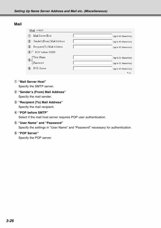
3-26
1
3
5
2
4
6
Setting Up Name Server Address and Mail etc. (Miscellaneous)
1 “Mail Server Host”
Specify the SMTP server.
2 “Sender’s (From) Mail Address”
Specify the mail sender.
3 “Recipient (To) Mail Address”
Specify the mail recipient.
4 “POP before SMTP”
Select if the mail host server requires POP user authentication.
5 “User Name” and “Password”
Specify the settings in “User Name” and “Password” necessary for authentication.
6 “POP Server”
Specify the POP server.COPY
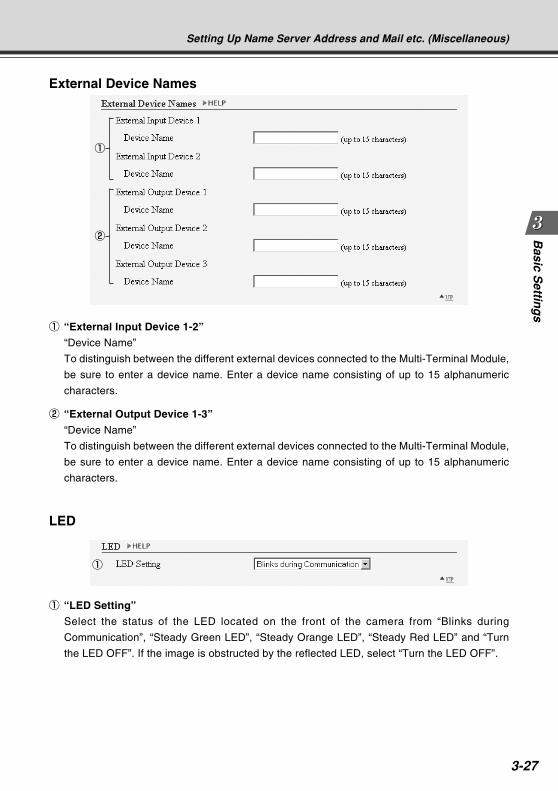
3-27
Basic S
etting
s
External Device Names
1
2
LED
1
Setting Up Name Server Address and Mail etc. (Miscellaneous)
1 “External Input Device 1-2”
“Device Name”
To distinguish between the different external devices connected to the Multi-Terminal Module,
be sure to enter a device name. Enter a device name consisting of up to 15 alphanumeric
characters.
2 “External Output Device 1-3”
“Device Name”
To distinguish between the different external devices connected to the Multi-Terminal Module,
be sure to enter a device name. Enter a device name consisting of up to 15 alphanumeric
characters.
1 “LED Setting”
Select the status of the LED located on the front of the camera from “Blinks during
Communication”, “Steady Green LED”, “Steady Orange LED”, “Steady Red LED” and “Turn
the LED OFF”. If the image is obstructed by the reflected LED, select “Turn the LED OFF”.
COPY
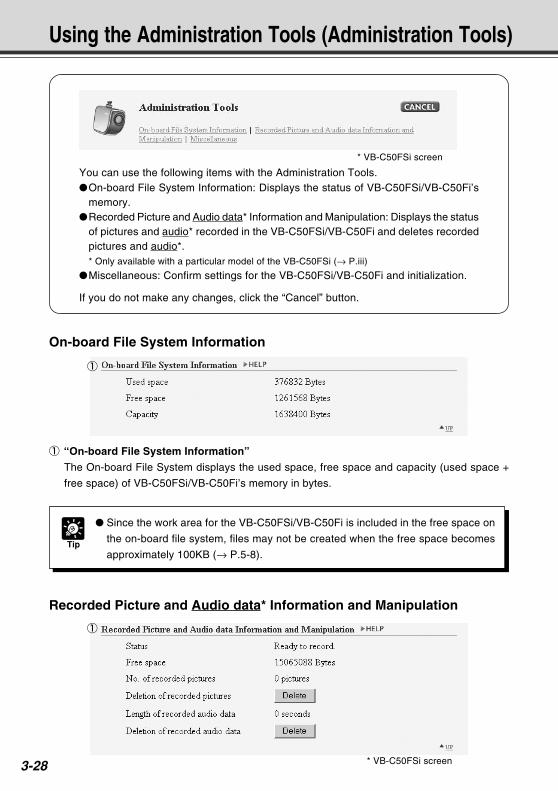
3-28
You can use the following items with the Administration Tools.On-board File System Information: Displays the status of VB-C50FSi/VB-C50Fi’s
memory.Recorded Picture and Audio data* Information and Manipulation: Displays the status
of pictures and audio* recorded in the VB-C50FSi/VB-C50Fi and deletes recordedpictures and audio*.* Only available with a particular model of the VB-C50FSi (→ P.iii)
Miscellaneous: Confirm settings for the VB-C50FSi/VB-C50Fi and initialization.
If you do not make any changes, click the “Cancel” button.
Using the Administration Tools (Administration Tools)
On-board File System Information
1 “On-board File System Information”
The On-board File System displays the used space, free space and capacity (used space +
free space) of VB-C50FSi/VB-C50Fi’s memory in bytes.
1
Tip
Since the work area for the VB-C50FSi/VB-C50Fi is included in the free space on
the on-board file system, files may not be created when the free space becomes
approximately 100KB (→ P.5-8).
Recorded Picture and Audio data* Information and Manipulation
1
* VB-C50FSi screen
* VB-C50FSi screen
COPY
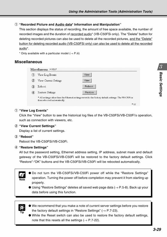
3-29
Basic S
etting
s
Miscellaneous
1 “View Log Events”
Click the “View” button to see the historical log files of the VB-C50FSi/VB-C50Fi’s operation,
such as connection with viewers, etc.
2 “View Current Settings”
Display a list of current settings.
3 “Reboot”
Reboot the VB-C50FSi/VB-C50Fi.
4 “Restore Settings”
All but the password setting, Ethernet address setting, IP address, subnet mask and default
gateway of the VB-C50FSi/VB-C50Fi will be restored to the factory default settings. Click
“Restore”-“OK” buttons and the VB-C50FSi/VB-C50Fi will be rebooted automatically.
1
3
2
4
Using the Administration Tools (Administration Tools)
Tip
We recommend that you make a note of current server settings before you restore
the factory default settings in “Restore Settings” (→ P.7-23).
While the Reset switch can also be used to restore the factory default settings,
note that this resets all the settings (→ P.7-22).
Note
Do not turn the VB-C50FSi/VB-C50Fi power off while the “Restore Settings”
operation. Turning the power off before completion may prevent it from starting up
properly.
Using “Restore Settings” deletes all saved web page data (→ P.5-8). Back up your
data before using this function.
1 “Recorded Picture and Audio data* Information and Manipulation”
This section displays the status of recording, the amount of free space available, the number of
recorded images and the duration of recorded audio* (VB-C50FSi only). The “Delete” button for
deleting recorded pictures can also be used to delete all the recorded pictures, and the “Delete”
button for deleting recorded audio (VB-C50FSi only) can also be used to delete all the recorded
audio*.
* Only available with a particular model (→ P.iii)
COPY

3-30
COPY
VB Administration ToolsChapter 4 describes practical ways of operating the VB-
C50FSi/VB-C50Fi using the VB Administration Tools to set
view restrictions, set presets and schedules, view logs and
use the Admin Viewer. Review the necessary basic settings
in Chapter 3 before proceeding to Chapter 4.
* Although view restrictions and presets can be set by
following the procedures described in Chapter 3, the VB
Administration Tools provides more visual-based and easy
way to use.
Chapter
COPY
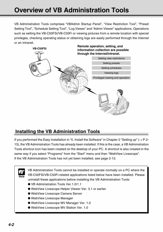
4-2
Overview of VB Administration Tools
VB Administration Tools comprises “VBAdmin Startup Panel”, “View Restriction Tool”, “Preset
Setting Tool”, “Schedule Setting Tool”, “Log Viewer” and “Admin Viewer” applications. Operations
such as setting the VB-C50FSi/VB-C50Fi or viewing pictures from a remote location with special
privileges, checking operating status or obtaining logs are easily performed through the Internet
or an intranet.
Installing the VB Administration Tools
If you performed the Easy Installation in “5. Install the Software” in Chapter 2 “Setting up” (→ P.2-
13), the VB Administration Tools has already been installed. If this is the case, a VB Administration
Tools shortcut icon has been created on the desktop of your PC. A shortcut is also created in the
same way if you select “Programs” from the “Start” menu and then “WebView Livescope”.
If the VB Administration Tools has not yet been installed, see page 2-13.
Note
VB Administration Tools cannot be installed or operate normally on a PC where the
VB-C50FSi/VB-C50Fi-related applications listed below have been installed. Please
uninstall these applications before installing the VB Administration Tools:
VB Administration Tools Ver.1.0/1.1
WebView Livescope Helper Viewer Ver. 3.1 or earlier
WebView Livescope Camera Server
WebView Livescope Manager
WebView Livescope MV Manager Ver. 1.0
WebView Livescope MV Station Ver. 1.0
Viewing logs
VB-C50FSi
Privileged viewing and operation
Setting schedules
Setting view restrictions
Setting presets
Remote operation, setting, and information collection are possible through the Internet/intranet.
COPY
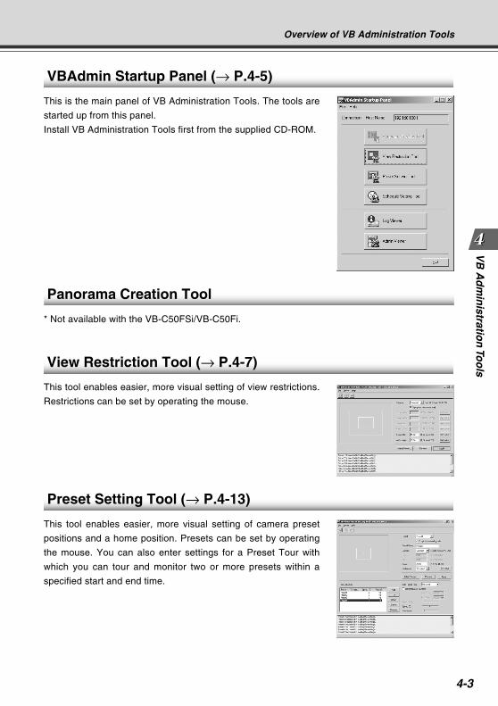
4-3
VB
Ad
min
istration
Too
ls
VBAdmin Startup Panel (→ P.4-5)
This is the main panel of VB Administration Tools. The tools are
started up from this panel.
Install VB Administration Tools first from the supplied CD-ROM.
Panorama Creation Tool
* Not available with the VB-C50FSi/VB-C50Fi.
View Restriction Tool (→ P.4-7)
This tool enables easier, more visual setting of view restrictions.
Restrictions can be set by operating the mouse.
Preset Setting Tool (→ P.4-13)
This tool enables easier, more visual setting of camera preset
positions and a home position. Presets can be set by operating
the mouse. You can also enter settings for a Preset Tour with
which you can tour and monitor two or more presets within a
specified start and end time.
Overview of VB Administration Tools
COPY
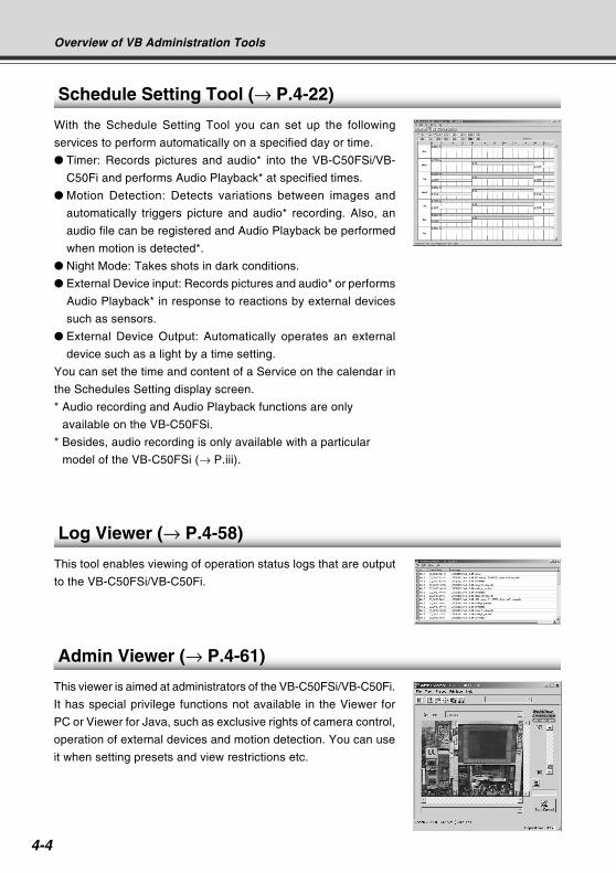
4-4
Overview of VB Administration Tools
Admin Viewer (→ P.4-61)
This viewer is aimed at administrators of the VB-C50FSi/VB-C50Fi.
It has special privilege functions not available in the Viewer for
PC or Viewer for Java, such as exclusive rights of camera control,
operation of external devices and motion detection. You can use
it when setting presets and view restrictions etc.
Schedule Setting Tool (→ P.4-22)
With the Schedule Setting Tool you can set up the following
services to perform automatically on a specified day or time.
Timer: Records pictures and audio* into the VB-C50FSi/VB-
C50Fi and performs Audio Playback* at specified times.
Motion Detection: Detects variations between images and
automatically triggers picture and audio* recording. Also, an
audio file can be registered and Audio Playback be performed
when motion is detected*.
Night Mode: Takes shots in dark conditions.
External Device input: Records pictures and audio* or performs
Audio Playback* in response to reactions by external devices
such as sensors.
External Device Output: Automatically operates an external
device such as a light by a time setting.
You can set the time and content of a Service on the calendar in
the Schedules Setting display screen.
* Audio recording and Audio Playback functions are only
available on the VB-C50FSi.
* Besides, audio recording is only available with a particular
model of the VB-C50FSi (→ P.iii).
Log Viewer (→ P.4-58)
This tool enables viewing of operation status logs that are output
to the VB-C50FSi/VB-C50Fi.COPY
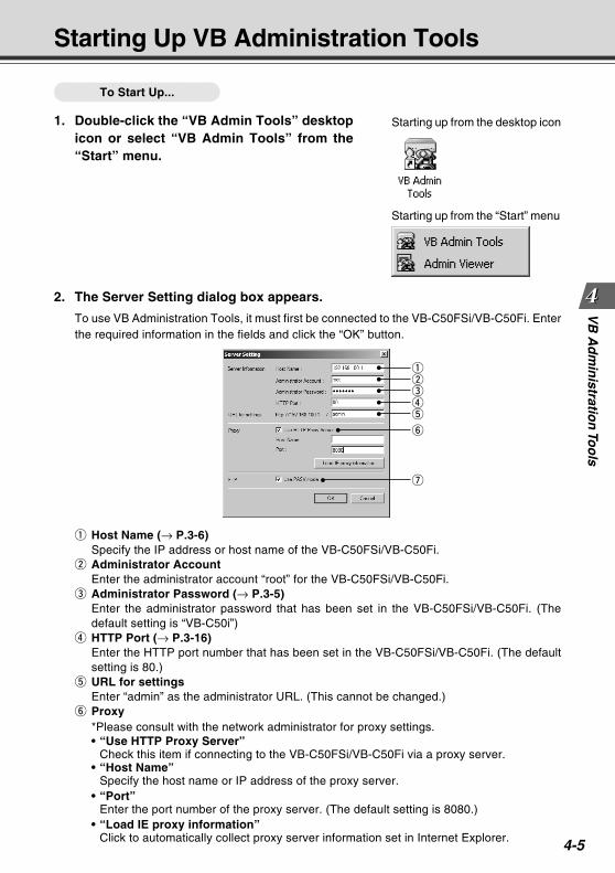
4-5
VB
Ad
min
istration
Too
lsStarting Up VB Administration Tools
To Start Up...
1. Double-click the “VB Admin Tools” desktopicon or select “VB Admin Tools” from the“Start” menu.
Starting up from the desktop icon
Starting up from the “Start” menu
2. The Server Setting dialog box appears.
To use VB Administration Tools, it must first be connected to the VB-C50FSi/VB-C50Fi. Enterthe required information in the fields and click the “OK” button.
q Host Name (→ P.3-6)Specify the IP address or host name of the VB-C50FSi/VB-C50Fi.
w Administrator AccountEnter the administrator account “root” for the VB-C50FSi/VB-C50Fi.
e Administrator Password (→ P.3-5)Enter the administrator password that has been set in the VB-C50FSi/VB-C50Fi. (Thedefault setting is “VB-C50i”)
r HTTP Port (→ P.3-16)Enter the HTTP port number that has been set in the VB-C50FSi/VB-C50Fi. (The defaultsetting is 80.)
t URL for settingsEnter “admin” as the administrator URL. (This cannot be changed.)
y Proxy*Please consult with the network administrator for proxy settings.• “Use HTTP Proxy Server”
Check this item if connecting to the VB-C50FSi/VB-C50Fi via a proxy server.• “Host Name”
Specify the host name or IP address of the proxy server.• “Port”
Enter the port number of the proxy server. (The default setting is 8080.)• “Load IE proxy information”
Click to automatically collect proxy server information set in Internet Explorer.
qwert
y
u
COPY
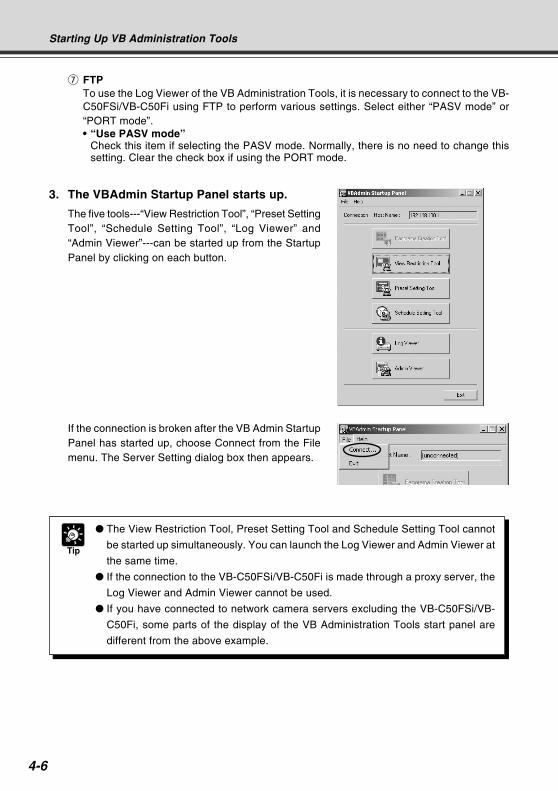
4-6
3. The VBAdmin Startup Panel starts up.
The five tools---“View Restriction Tool”, “Preset SettingTool”, “Schedule Setting Tool”, “Log Viewer” and“Admin Viewer”---can be started up from the StartupPanel by clicking on each button.
If the connection is broken after the VB Admin StartupPanel has started up, choose Connect from the Filemenu. The Server Setting dialog box then appears.
Tip
The View Restriction Tool, Preset Setting Tool and Schedule Setting Tool cannot
be started up simultaneously. You can launch the Log Viewer and Admin Viewer at
the same time.
If the connection to the VB-C50FSi/VB-C50Fi is made through a proxy server, the
Log Viewer and Admin Viewer cannot be used.
If you have connected to network camera servers excluding the VB-C50FSi/VB-
C50Fi, some parts of the display of the VB Administration Tools start panel are
different from the above example.
Starting Up VB Administration Tools
u FTPTo use the Log Viewer of the VB Administration Tools, it is necessary to connect to the VB-C50FSi/VB-C50Fi using FTP to perform various settings. Select either “PASV mode” or“PORT mode”.• “Use PASV mode”
Check this item if selecting the PASV mode. Normally, there is no need to change thissetting. Clear the check box if using the PORT mode.
COPY
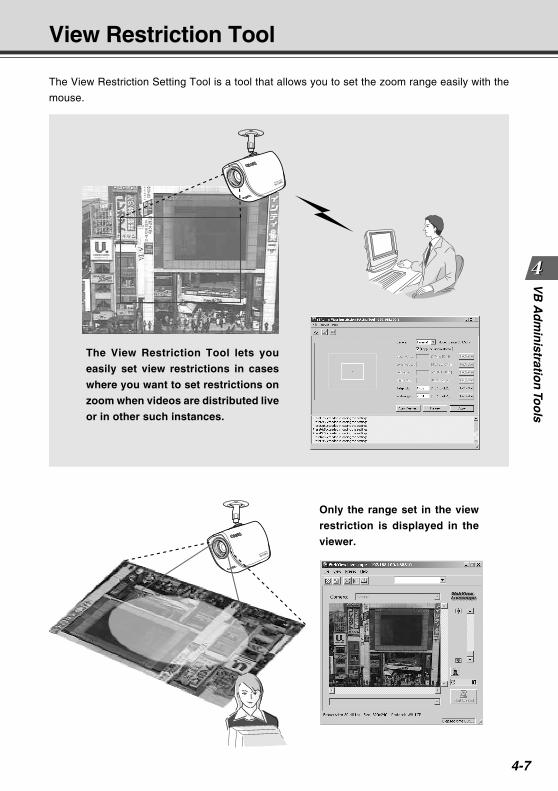
4-7
VB
Ad
min
istration
Too
ls
The View Restriction Setting Tool is a tool that allows you to set the zoom range easily with the
mouse.
The View Restriction Tool lets you
easily set view restrictions in cases
where you want to set restrictions on
zoom when videos are distributed live
or in other such instances.
View Restriction Tool
Only the range set in the view
restriction is displayed in the
viewer.COPY
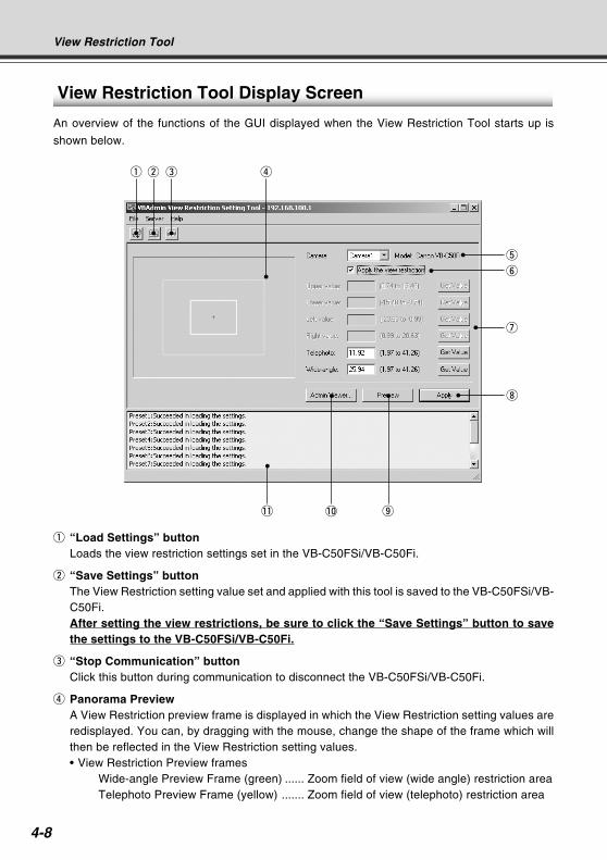
4-8
View Restriction Tool Display Screen
An overview of the functions of the GUI displayed when the View Restriction Tool starts up is
shown below.
q e r
t
y
u
i
!1 !0 o
q “Load Settings” buttonLoads the view restriction settings set in the VB-C50FSi/VB-C50Fi.
w “Save Settings” buttonThe View Restriction setting value set and applied with this tool is saved to the VB-C50FSi/VB-C50Fi.After setting the view restrictions, be sure to click the “Save Settings” button to savethe settings to the VB-C50FSi/VB-C50Fi.
e “Stop Communication” buttonClick this button during communication to disconnect the VB-C50FSi/VB-C50Fi.
r Panorama PreviewA View Restriction preview frame is displayed in which the View Restriction setting values areredisplayed. You can, by dragging with the mouse, change the shape of the frame which willthen be reflected in the View Restriction setting values.• View Restriction Preview frames
Wide-angle Preview Frame (green) ...... Zoom field of view (wide angle) restriction areaTelephoto Preview Frame (yellow) ....... Zoom field of view (telephoto) restriction area
w
View Restriction Tool
COPY
4-9
VB
Ad
min
istration
Too
lsView Restriction Tool
t Camera Selection boxAnother camera cannot be selected with the VB-C50FSi/VB-C50Fi.
y “Apply the view restriction”View restriction settings are applied when this item is selected.
u View Restriction Value Input boxes and “Get Value” buttonThe view restriction settings can be edited by entering values in the View Restriction ValueInput boxes. When the “Get Value” button is clicked, the current angle of the camera can beretrieved and reflected in each setting value listed below.• View restriction setting values
Telephoto ............ Value for the telephoto limit of the view restriction. The zoom value of theselected camera angle is obtained using the “Get Value” button.
Wide-angle .......... Value for the wide-angle limit of the view restriction. The zoom value ofthe selected camera angle is obtained using the “Get Value” button.
* Upper value, Lower value, Left value and Right value cannot be set with the VB-C50FSi/VB-C50Fi.
i “Apply” buttonApplies the current view restriction settings to the VB-C50FSi/VB-C50Fi. At this stage, theedited settings are not yet saved to the VB-C50FSi/VB-C50Fi. Be sure to click the “Save Setting”button to save the settings to the VB-C50FSi/VB-C50Fi.
o “Preview” buttonClicking this button allows checking of the set values specified in the View Restriction ValueInput boxes with the View Restriction Preview frame.
!0 “Admin Viewer” buttonThis button can be used to start up Admin Viewer.
!1 Status ListDisplays the results of communication between this tool and the VB-C50FSi/VB-C50Fi. Warningmessages are displayed in blue and error messages are displayed in red.
Note
You cannot set view restriction for an external camera. For this reason, the only
camera you can select in the Camera Selection box is “Camera 1”.
Edited content is not saved to the VB-C50FSi/VB-C50Fi when the “Apply” button is
clicked. The edited content will only come into effect when the “Save Setting” button
is clicked.
COPY
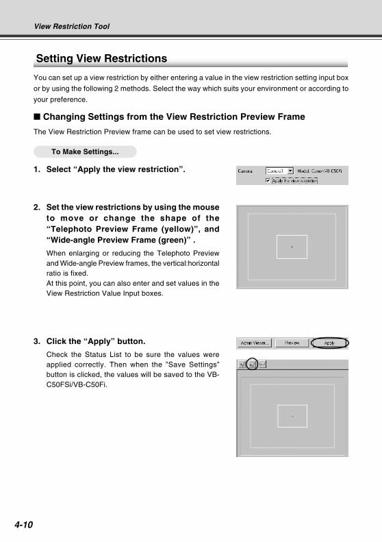
4-10
Setting View Restrictions
You can set up a view restriction by either entering a value in the view restriction setting input box
or by using the following 2 methods. Select the way which suits your environment or according to
your preference.
Changing Settings from the View Restriction Preview Frame
The View Restriction Preview frame can be used to set view restrictions.
To Make Settings...
1. Select “Apply the view restriction”.
View Restriction Tool
2. Set the view restrictions by using the mouseto move or change the shape of the“Telephoto Preview Frame (yellow)”, and“Wide-angle Preview Frame (green)” .
When enlarging or reducing the Telephoto Previewand Wide-angle Preview frames, the vertical:horizontalratio is fixed.At this point, you can also enter and set values in theView Restriction Value Input boxes.
3. Click the “Apply” button.
Check the Status List to be sure the values wereapplied correctly. Then when the ”Save Settings”button is clicked, the values will be saved to the VB-C50FSi/VB-C50Fi.
COPY
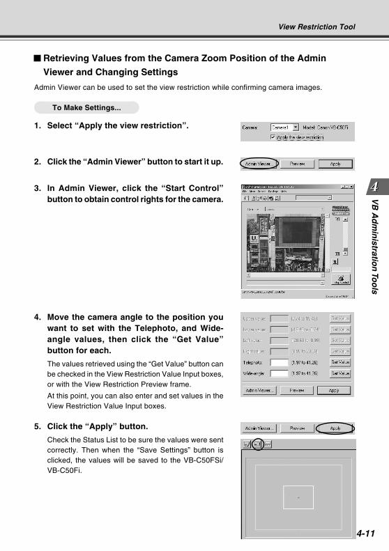
4-11
VB
Ad
min
istration
Too
lsView Restriction Tool
Retrieving Values from the Camera Zoom Position of the Admin
Viewer and Changing Settings
Admin Viewer can be used to set the view restriction while confirming camera images.
To Make Settings...
1. Select “Apply the view restriction”.
2. Click the “Admin Viewer” button to start it up.
3. In Admin Viewer, click the “Start Control”button to obtain control rights for the camera.
4. Move the camera angle to the position youwant to set with the Telephoto, and Wide-angle values, then click the “Get Value”button for each.
The values retrieved using the “Get Value” button canbe checked in the View Restriction Value Input boxes,or with the View Restriction Preview frame.
At this point, you can also enter and set values in theView Restriction Value Input boxes.
5. Click the “Apply” button.
Check the Status List to be sure the values were sentcorrectly. Then when the “Save Settings” button isclicked, the values will be saved to the VB-C50FSi/VB-C50Fi.
COPY
4-12
Note
After the view restrictions have been set, please check to be sure that the view
restrictions are correctly reflected in the Viewer. When checking from the Admin
Viewer, choose “View Restriction” - “ON” from the “Privilege” menu bar (→ P.4-64).
View Restriction Tool
Tip
When you want to clear the view restriction settings, clear the “Apply the view
restriction” check box, click the “Apply” button and then the “Save Settings” button.
Even if the “Apply the view restriction” is selected, view restriction is not applied
when an input box is left blank. In this case, the maximum value is applied.
COPY
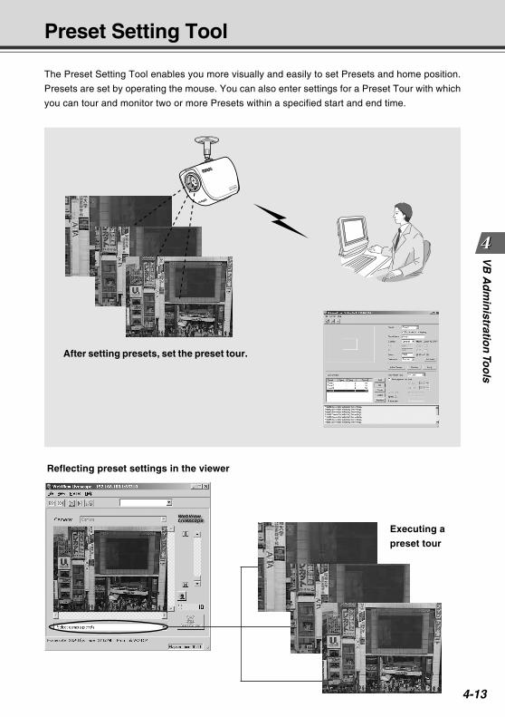
4-13
VB
Ad
min
istration
Too
lsPreset Setting Tool
The Preset Setting Tool enables you more visually and easily to set Presets and home position.
Presets are set by operating the mouse. You can also enter settings for a Preset Tour with which
you can tour and monitor two or more Presets within a specified start and end time.
After setting presets, set the preset tour.
Reflecting preset settings in the viewer
Executing a
preset tour
COPY
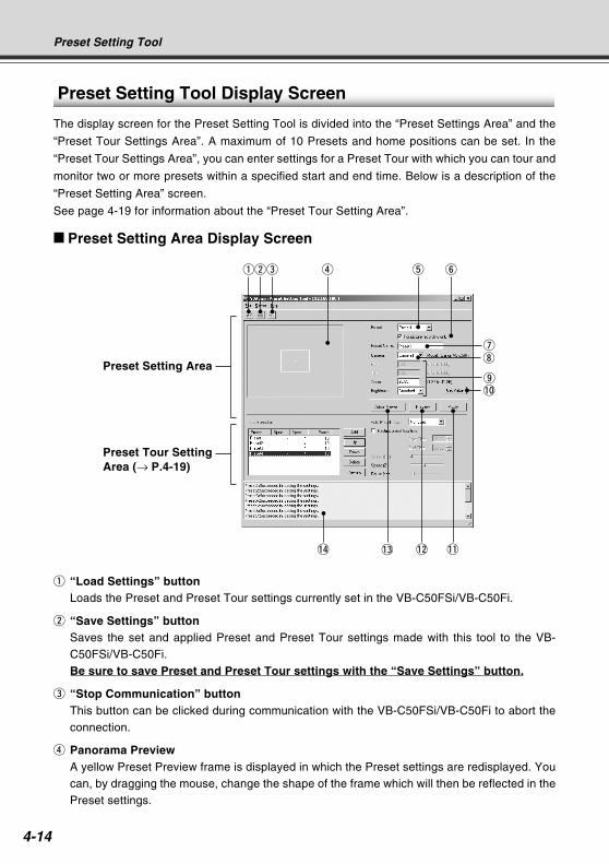
4-14
Preset Setting Tool
Preset Setting Tool Display Screen
The display screen for the Preset Setting Tool is divided into the “Preset Settings Area” and the
“Preset Tour Settings Area”. A maximum of 10 Presets and home positions can be set. In the
“Preset Tour Settings Area”, you can enter settings for a Preset Tour with which you can tour and
monitor two or more presets within a specified start and end time. Below is a description of the
“Preset Setting Area” screen.
See page 4-19 for information about the “Preset Tour Setting Area”.
Preset Setting Area Display Screen
q “Load Settings” buttonLoads the Preset and Preset Tour settings currently set in the VB-C50FSi/VB-C50Fi.
w “Save Settings” buttonSaves the set and applied Preset and Preset Tour settings made with this tool to the VB-C50FSi/VB-C50Fi.Be sure to save Preset and Preset Tour settings with the “Save Settings” button.
e “Stop Communication” buttonThis button can be clicked during communication with the VB-C50FSi/VB-C50Fi to abort theconnection.
r Panorama PreviewA yellow Preset Preview frame is displayed in which the Preset settings are redisplayed. Youcan, by dragging the mouse, change the shape of the frame which will then be reflected in thePreset settings.
qwe r t y
ui
o!0
!1!2!3!4
Preset Tour SettingArea (→ P.4-19)
Preset Setting Area
COPY
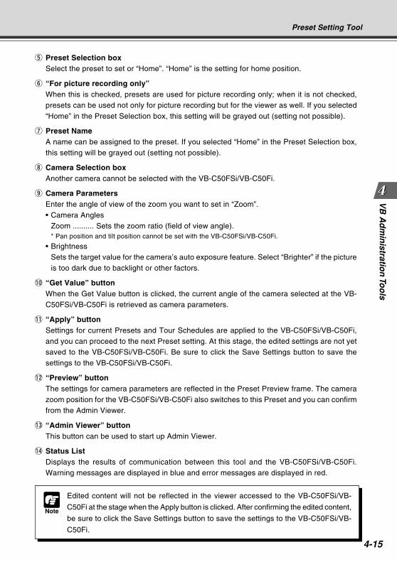
4-15
VB
Ad
min
istration
Too
lsPreset Setting Tool
t Preset Selection boxSelect the preset to set or “Home”. “Home” is the setting for home position.
y “For picture recording only”When this is checked, presets are used for picture recording only; when it is not checked,presets can be used not only for picture recording but for the viewer as well. If you selected“Home” in the Preset Selection box, this setting will be grayed out (setting not possible).
u Preset NameA name can be assigned to the preset. If you selected “Home” in the Preset Selection box,this setting will be grayed out (setting not possible).
i Camera Selection boxAnother camera cannot be selected with the VB-C50FSi/VB-C50Fi.
o Camera ParametersEnter the angle of view of the zoom you want to set in “Zoom”.• Camera Angles
Zoom .......... Sets the zoom ratio (field of view angle).* Pan position and tilt position cannot be set with the VB-C50FSi/VB-C50Fi.
• BrightnessSets the target value for the camera’s auto exposure feature. Select “Brighter” if the pictureis too dark due to backlight or other factors.
!0 “Get Value” buttonWhen the Get Value button is clicked, the current angle of the camera selected at the VB-C50FSi/VB-C50Fi is retrieved as camera parameters.
!1 “Apply” buttonSettings for current Presets and Tour Schedules are applied to the VB-C50FSi/VB-C50Fi,and you can proceed to the next Preset setting. At this stage, the edited settings are not yetsaved to the VB-C50FSi/VB-C50Fi. Be sure to click the Save Settings button to save thesettings to the VB-C50FSi/VB-C50Fi.
!2 “Preview” buttonThe settings for camera parameters are reflected in the Preset Preview frame. The camerazoom position for the VB-C50FSi/VB-C50Fi also switches to this Preset and you can confirmfrom the Admin Viewer.
!3 “Admin Viewer” buttonThis button can be used to start up Admin Viewer.
!4 Status ListDisplays the results of communication between this tool and the VB-C50FSi/VB-C50Fi.Warning messages are displayed in blue and error messages are displayed in red.
Note
Edited content will not be reflected in the viewer accessed to the VB-C50FSi/VB-
C50Fi at the stage when the Apply button is clicked. After confirming the edited content,
be sure to click the Save Settings button to save the settings to the VB-C50FSi/VB-
C50Fi.
COPY
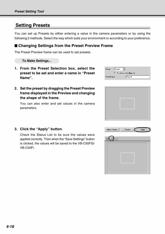
4-16
Preset Setting Tool
Setting Presets
You can set up Presets by either entering a value in the camera parameters or by using the
following 2 methods. Select the way which suits your environment or according to your preference.
Changing Settings from the Preset Preview Frame
The Preset Preview frame can be used to set presets.
To Make Settings...
1. From the Preset Selection box, select thepreset to be set and enter a name in “PresetName”.
2. Set the preset by dragging the Preset Previewframe displayed in the Preview and changingthe shape of the frame.
You can also enter and set values in the cameraparameters.
3. Click the “Apply” button.
Check the Status List to be sure the values wereapplied correctly. Then when the “Save Settings” buttonis clicked, the values will be saved to the VB-C50FSi/VB-C50Fi. CO
PY
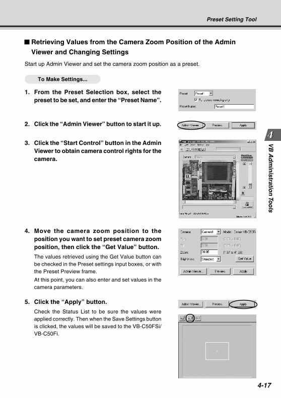
4-17
VB
Ad
min
istration
Too
ls
Retrieving Values from the Camera Zoom Position of the Admin
Viewer and Changing Settings
Start up Admin Viewer and set the camera zoom position as a preset.
To Make Settings...
1. From the Preset Selection box, select thepreset to be set, and enter the “Preset Name”.
Preset Setting Tool
2. Click the “Admin Viewer” button to start it up.
3. Click the “Start Control” button in the AdminViewer to obtain camera control rights for thecamera.
4. Move the camera zoom position to theposition you want to set preset camera zoomposition, then click the “Get Value” button.
The values retrieved using the Get Value button canbe checked in the Preset settings input boxes, or withthe Preset Preview frame.
At this point, you can also enter and set values in thecamera parameters.
5. Click the “Apply” button.
Check the Status List to be sure the values wereapplied correctly. Then when the Save Settings buttonis clicked, the values will be saved to the VB-C50FSi/VB-C50Fi.
COPY
4-18
Tip
You can set a maximum of 10 presets.
Changes in the preset settings are not reflected to the viewer while it is connected.
After the presets have been set, please check to be sure that the presets are
correctly reflected in the Viewer.
Once presets have been set, they cannot be deleted. If you do not want to these
presets to be used, select “For picture recording only” (→ P.4-15) so that the presets
cannot be used in the Viewer for PC.
Preset Setting Tool
COPY
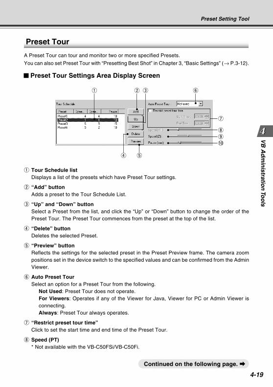
4-19
VB
Ad
min
istration
Too
ls
Preset Tour
A Preset Tour can tour and monitor two or more specified Presets.
You can also set Preset Tour with “Presetting Best Shot” in Chapter 3, “Basic Settings” (→ P.3-12).
Preset Tour Settings Area Display Screen
q w y
i
o
!0
q Tour Schedule listDisplays a list of the presets which have Preset Tour settings.
w “Add” buttonAdds a preset to the Tour Schedule List.
e “Up” and “Down” buttonSelect a Preset from the list, and click the “Up” or “Down” button to change the order of thePreset Tour. The Preset Tour commences from the preset at the top of the list.
r “Delete” buttonDeletes the selected Preset.
t “Preview” buttonReflects the settings for the selected preset in the Preset Preview frame. The camera zoompositions set in the device switch to the specified values and can be confirmed from the AdminViewer.
y Auto Preset TourSelect an option for a Preset Tour from the following.
Not Used: Preset Tour does not operate.For Viewers: Operates if any of the Viewer for Java, Viewer for PC or Admin Viewer isconnecting.Always: Preset Tour always operates.
u “Restrict preset tour time”Click to set the start time and end time of the Preset Tour.
i Speed (PT)* Not available with the VB-C50FSi/VB-C50Fi.
r t
e
u
Preset Setting Tool
Continued on the following page. a
COPY
4-20
Tip
Preset Tour does not operate when the camera is being controlled with the Viewer
for PC, or the Admin Viewer and so on.
Preset Setting Tool
o Speed (Z)Sets the speed at which the camera moves when zooming, within a range of 1-8. By movingthe slide bar from left to right, the numeric value becomes larger and the speed increases.
!0 Pause (sec)Sets the time for which the camera pauses in the preset position, within a range of 0-120seconds in units of five seconds.
COPY
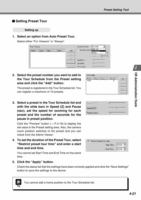
4-21
VB
Ad
min
istration
Too
ls
2. Select the preset number you want to add tothe Tour Schedule from the Preset settingarea and click the “Add” button.
The preset is registered in the Tour Schedule list. Youcan register a maximum of 10 presets.
Setting Preset Tour
Setting up
1. Select an option from Auto Preset Tour.
Select either “For Viewers” or “Always”.
TipYou cannot add a home position to the Tour Schedule list.
Preset Setting Tool
3. Select a preset in the Tour Schedule list andwith the slide bars in Speed (Z) and Pause(sec), set the speed for zooming for eachpreset and the number of seconds for thepause in preset position.
Click the “Preview” button (→ P.4-19) to display theset value in the Preset setting area. Also, the camerazoom position switches to the preset and you cancheck from the Admin Viewer.
4. To set the duration of the Preset Tour, select“Restrict preset tour time” and enter a starttime and end time.
You cannot set Start Time and End Time on the sametime.
5. Click the “Apply” button.
Check the status list that the settings have been correctly applied and click the “Save Settings”button to save the settings to the device.
COPY
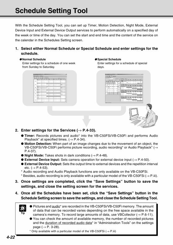
4-22
Schedule Setting Tool
With the Schedule Setting Tool, you can set up Timer, Motion Detection, Night Mode, External
Device Input and External Device Output services to perform automatically on a specified day of
the week or time of the day. You can set the start and end time and the content of the service on
the calendar in the Schedules Setting screen.
2. Enter settings for the Services (→ P.4-33). Timer: Records pictures and audio* into the VB-C50FSi/VB-C50Fi and performs Audio
Playback* at specified times. (→ P.4-34). Motion Detection: When part of an image changes due to the movement of an object, the
VB-C50FSi/VB-C50Fi performs picture recording, audio recording* or Audio Playback* (→P.4-37).
Night Mode: Takes shots in dark conditions (→ P.4-48). External Device Input: Sets camera operation for external device input (→ P.4-50). External Device Output: Sets the output time to external devices and the repetition interval
etc. (→ P.4-53).* Audio recording and Audio Playback functions are only available on the VB-C50FSi.* Besides, audio recording is only available with a particular model of the VB-C50FSi (→ P.iii).
3. Once settings are completed, click the “Save Settings” button to save thesettings, and close the setting screen for the services.
4. Once all the Schedules have been set, click the “Save Settings” button in theSchedule Setting screen to save the settings, and close the Schedule Setting Tool.
Tip
Pictures and audio* are recorded in the VB-C50FSi/VB-C50Fi memory. The amountof data that can be recorded varies depending on the free space available in thecamera’s memory. To record large amounts of data, use VBCollector (→ P.6-11).
You can check the amount of available memory, the number of recorded picturesand the duration of recorded audio data* in “Administration Tools” on the settingspage (→ P. 3-28).
* Only available with a particular model of the VB-C50FSi (→ P.iii)
Normal ScheduleEnter settings for a schedule of one weekfrom Sunday to Saturday.
Special ScheduleEnter settings for a schedule of specialdays.
1. Select either Normal Schedule or Special Schedule and enter settings for theschedule.
COPY
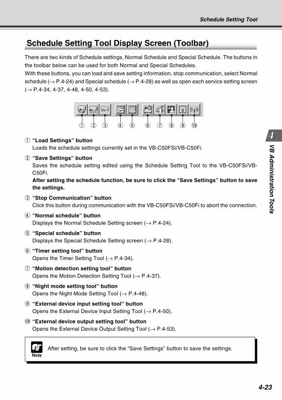
4-23
VB
Ad
min
istration
Too
ls
Schedule Setting Tool Display Screen (Toolbar)
There are two kinds of Schedule settings, Normal Schedule and Special Schedule. The buttons in
the toolbar below can be used for both Normal and Special Schedules.
With these buttons, you can load and save setting information, stop communication, select Normal
schedule (→ P.4-24) and Special schedule (→ P.4-28) as well as open each service setting screen
(→ P.4-34, 4-37, 4-48, 4-50, 4-53).
q “Load Settings” buttonLoads the schedule settings currently set in the VB-C50FSi/VB-C50Fi.
w “Save Settings” buttonSaves the schedule setting edited using the Schedule Setting Tool to the VB-C50FSi/VB-C50Fi.After setting the schedule function, be sure to click the “Save Settings” button to savethe settings.
e “Stop Communication” buttonClick this button during communication with the VB-C50FSi/VB-C50Fi to abort the connection.
r “Normal schedule” buttonDisplays the Normal Schedule Setting screen (→ P.4-24).
t “Special schedule” buttonDisplays the Special Schedule Setting screen (→ P.4-28).
y “Timer setting tool” buttonOpens the Timer Setting Tool (→ P.4-34).
u “Motion detection setting tool” buttonOpens the Motion Detection Setting Tool (→ P.4-37).
i “Night mode setting tool” buttonOpens the Night Mode Setting Tool (→ P.4-48).
o “External device input setting tool” buttonOpens the External Device Input Setting Tool (→ P.4-50).
!0 “External device output setting tool” buttonOpens the External Device Output Setting Tool (→ P.4-53).
NoteAfter setting, be sure to click the “Save Settings” button to save the settings.
Schedule Setting Tool
q w e r t y u i o !0
COPY
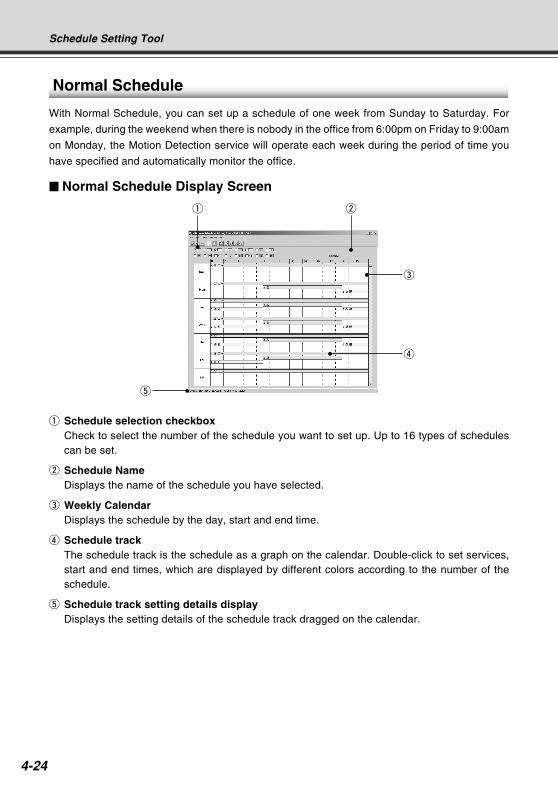
4-24
Normal Schedule
With Normal Schedule, you can set up a schedule of one week from Sunday to Saturday. For
example, during the weekend when there is nobody in the office from 6:00pm on Friday to 9:00am
on Monday, the Motion Detection service will operate each week during the period of time you
have specified and automatically monitor the office.
Normal Schedule Display Screen
q w
e
r
t
q Schedule selection checkboxCheck to select the number of the schedule you want to set up. Up to 16 types of schedulescan be set.
w Schedule NameDisplays the name of the schedule you have selected.
e Weekly CalendarDisplays the schedule by the day, start and end time.
r Schedule trackThe schedule track is the schedule as a graph on the calendar. Double-click to set services,start and end times, which are displayed by different colors according to the number of theschedule.
t Schedule track setting details displayDisplays the setting details of the schedule track dragged on the calendar.
Schedule Setting Tool
COPY
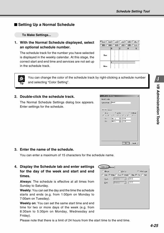
4-25
VB
Ad
min
istration
Too
ls
Setting Up a Normal Schedule
To Make Settings...
1. With the Normal Schedule displayed, selectan optional schedule number.
The schedule track for the number you have selectedis displayed in the weekly calendar. At this stage, thecorrect start and end time and services are not set upin the schedule track.
Schedule Setting Tool
2. Double-click the schedule track.
The Normal Schedule Settings dialog box appears.Enter settings for the schedule.
3. Enter the name of the schedule.
You can enter a maximum of 15 characters for the schedule name.
4. Display the Schedule tab and enter settingsfor the day of the week and start and endtimes.
Always: The schedule is effective at all times fromSunday to Saturday.
Weekly: You can set the day and the time the schedulestarts and ends (e.g. from 1:00pm on Monday to7:00am on Tuesday).
Weekly on: You can set the same start time and endtime for two or more days of the week (e.g. from8:30am to 5:30pm on Monday, Wednesday andFriday).
Please note that there is a limit of 24 hours from the start time to the end time.
Tip
You can change the color of the schedule track by right-clicking a schedule number
and selecting “Color Setting”.
COPY
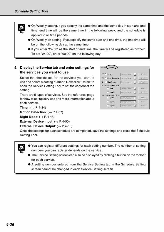
4-26
Schedule Setting Tool
Tip
On Weekly setting, if you specify the same time and the same day in start and end
time, end time will be the same time in the following week, and the schedule is
applied to all time periods.
On Weekly on setting, if you specify the same start and end time, the end time will
be on the following day at the same time.
If you enter “24:00” as the start or end time, the time will be registered as “23:59”.
To set “24:00”, enter “00:00” on the following day.
5. Display the Service tab and enter settings forthe services you want to use.
Select the checkboxes for the services you want touse and select a setting number. Next click “Detail” toopen the Service Setting Tool to set the content of thesetting.
There are 5 types of services. See the reference pagefor how to set up services and more information abouteach service.
Timer: (→ P.4-34)
Motion Detection: (→ P.4-37)
Night Mode: (→ P.4-48)
External Device Input: (→ P.4-50)
External Device Output: (→ P.4-53)
Once the settings for each schedule are completed, save the settings and close the ScheduleSetting Tool.
Tip
You can register different settings for each setting number. The number of setting
numbers you can register depends on the service.
The Service Setting screen can also be displayed by clicking a button on the toolbar
for each service.
A setting number entered from the Service Setting tab in the Schedule Setting
screen cannot be changed in each Service Setting screen.
COPY
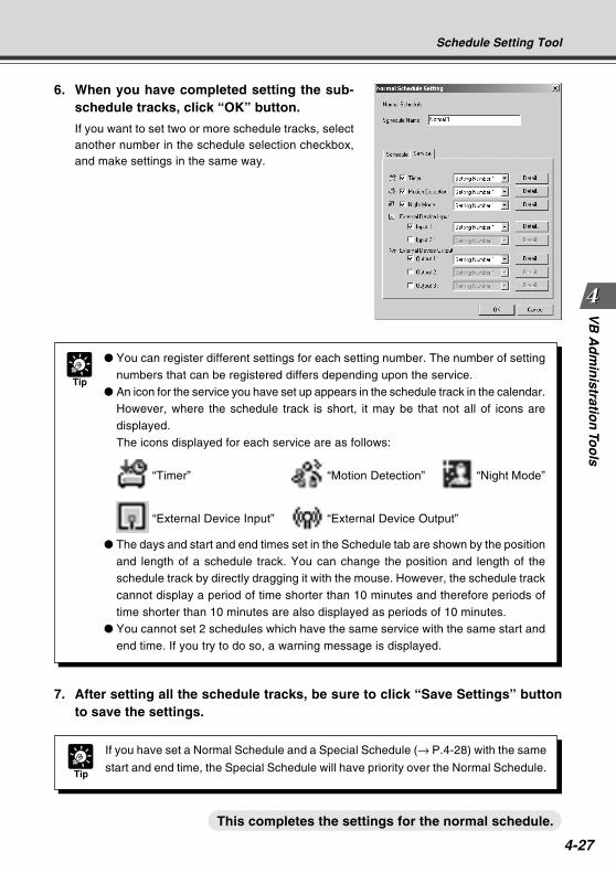
4-27
VB
Ad
min
istration
Too
ls
Tip
You can register different settings for each setting number. The number of settingnumbers that can be registered differs depending upon the service.
An icon for the service you have set up appears in the schedule track in the calendar.However, where the schedule track is short, it may be that not all of icons aredisplayed.The icons displayed for each service are as follows:
“Timer” “Motion Detection” “Night Mode”
“External Device Input” “External Device Output”
The days and start and end times set in the Schedule tab are shown by the positionand length of a schedule track. You can change the position and length of theschedule track by directly dragging it with the mouse. However, the schedule trackcannot display a period of time shorter than 10 minutes and therefore periods oftime shorter than 10 minutes are also displayed as periods of 10 minutes.
You cannot set 2 schedules which have the same service with the same start andend time. If you try to do so, a warning message is displayed.
Schedule Setting Tool
6. When you have completed setting the sub-schedule tracks, click “OK” button.
If you want to set two or more schedule tracks, selectanother number in the schedule selection checkbox,and make settings in the same way.
7. After setting all the schedule tracks, be sure to click “Save Settings” buttonto save the settings.
Tip
If you have set a Normal Schedule and a Special Schedule (→ P.4-28) with the same
start and end time, the Special Schedule will have priority over the Normal Schedule.
This completes the settings for the normal schedule.
COPY
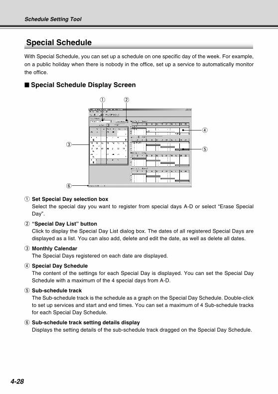
4-28
Special Schedule
With Special Schedule, you can set up a schedule on one specific day of the week. For example,
on a public holiday when there is nobody in the office, set up a service to automatically monitor
the office.
Special Schedule Display Screen
q Set Special Day selection boxSelect the special day you want to register from special days A-D or select “Erase SpecialDay”.
w “Special Day List” buttonClick to display the Special Day List dialog box. The dates of all registered Special Days aredisplayed as a list. You can also add, delete and edit the date, as well as delete all dates.
e Monthly CalendarThe Special Days registered on each date are displayed.
r Special Day ScheduleThe content of the settings for each Special Day is displayed. You can set the Special DaySchedule with a maximum of the 4 special days from A-D.
t Sub-schedule trackThe Sub-schedule track is the schedule as a graph on the Special Day Schedule. Double-clickto set up services and start and end times. You can set a maximum of 4 Sub-schedule tracksfor each Special Day Schedule.
y Sub-schedule track setting details displayDisplays the setting details of the sub-schedule track dragged on the Special Day Schedule.
q w
e
r
t
Schedule Setting Tool
y
COPY

4-29
VB
Ad
min
istration
Too
lsTip
You can only set one type of Special Day per day.
You can set one Special Day a maximum of 32 times.
You can also set up a Schedule by right-clicking on a date on the calendar.
You can add, delete, edit and delete all from the Special Day List dialog box by
clicking the Special Day List button.
Setting Up a Special Schedule
To Make Settings...
1. With the Special Schedule displayed, select from the Special Day selectionbox the Special Day you want to register in the Schedule.
Click the date on which you want to register a Schedule and the Special Day you have selectedis registered.
2. Select the optional sub-schedule track from the Special Day Schedule to beused.
In each Special Day Schedule, 4 Sub-schedule tracks have been provided. Select a Sub-schedule track to activate.
Schedule Setting Tool
Continued on the following page. a
COPY
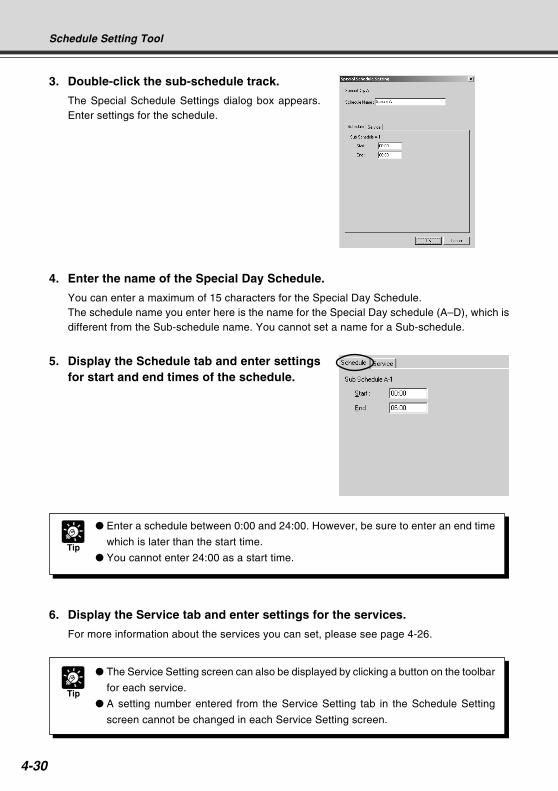
4-30
6. Display the Service tab and enter settings for the services.
For more information about the services you can set, please see page 4-26.
Tip
The Service Setting screen can also be displayed by clicking a button on the toolbar
for each service.
A setting number entered from the Service Setting tab in the Schedule Setting
screen cannot be changed in each Service Setting screen.
3. Double-click the sub-schedule track.
The Special Schedule Settings dialog box appears.Enter settings for the schedule.
4. Enter the name of the Special Day Schedule.
You can enter a maximum of 15 characters for the Special Day Schedule.The schedule name you enter here is the name for the Special Day schedule (A–D), which isdifferent from the Sub-schedule name. You cannot set a name for a Sub-schedule.
5. Display the Schedule tab and enter settingsfor start and end times of the schedule.
Tip
Enter a schedule between 0:00 and 24:00. However, be sure to enter an end time
which is later than the start time.
You cannot enter 24:00 as a start time.
Schedule Setting Tool
COPY
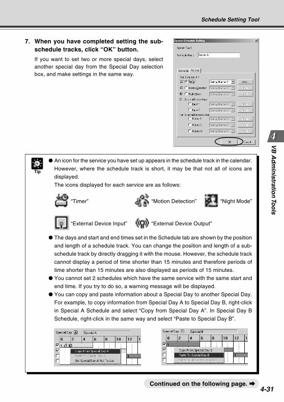
4-31
VB
Ad
min
istration
Too
lsSchedule Setting Tool
7. When you have completed setting the sub-schedule tracks, click “OK” button.
If you want to set two or more special days, selectanother special day from the Special Day selectionbox, and make settings in the same way.
Continued on the following page. a
Tip
An icon for the service you have set up appears in the schedule track in the calendar.
However, where the schedule track is short, it may be that not all of icons are
displayed.
The icons displayed for each service are as follows:
“Timer” “Motion Detection” “Night Mode”
“External Device Input” “External Device Output”
The days and start and end times set in the Schedule tab are shown by the position
and length of a schedule track. You can change the position and length of a sub-
schedule track by directly dragging it with the mouse. However, the schedule track
cannot display a period of time shorter than 15 minutes and therefore periods of
time shorter than 15 minutes are also displayed as periods of 15 minutes.
You cannot set 2 schedules which have the same service with the same start and
end time. If you try to do so, a warning message will be displayed.
You can copy and paste information about a Special Day to another Special Day.
For example, to copy information from Special Day A to Special Day B, right-click
in Special A Schedule and select “Copy from Special Day A”. In Special Day B
Schedule, right-click in the same way and select “Paste to Special Day B”.
COPY
4-32
Tip
If you have set up a Normal Schedule (→ P.4-24) and a Special Schedule with the same
start and end time, the Special Schedule will have priority over the Normal Schedule.
If you want to execute a Special day schedule on the same month and day each
year, right-click the Special Day registered on the date in the monthly calendar,
and select “Every Year”. When you have done so, the Special Day on the calendar
is displayed in red.
You cannot set “Every Year” on 29 February of a leap year.
This completes the settings for the special schedule.
Schedule Setting Tool
8. Once all the schedules have been set, click the “Save Settings” button in theSchedule Setting screen to save the schedules.
Resetting Schedule Settings
Resets schedules you have set.
1. In the Normal or Special Schedule Setting screen, select “Initialize normal(special) schedules” from Edit in the menu bar.
Tip
If you want to reset normal and special schedules at the same time, select “Initialize
all schedules and service settings” from Edit in the menu bar.
COPY
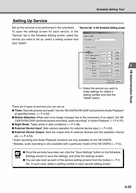
4-33
VB
Ad
min
istration
Too
ls
Setting Up Service
Set up the services to be performed in the schedules.
To open the settings screen for each service, in the
“Service” tab in the Schedule Setting screen, select the
service you want to set up, select a setting number and
click “Detail”.
There are 5 types of services you can set up.
Timer: Records pictures and audio* into the VB-C50FSi/VB-C50Fi and performs Audio Playback*at specified times. (→ P.4-34).
Motion Detection: When part of an image changes due to the movement of an object, the VB-C50FSi/VB-C50Fi performs picture recording, audio recording* or Audio Playback* (→ P.4-37).
Night Mode: Takes shots in dark conditions (→ P.4-48).
External Device Input: Sets camera operation for external device input (→ P.4-50).
External Device Output: Sets the output time to external devices and the repetition interval
etc. (→ P.4-53).
* Audio recording and Audio Playback functions are only available on the VB-C50FSi.
* Besides, audio recording is only available with a particular model of the VB-C50FSi (→ P.iii).
Note
Once the services have been set, click the “Save Settings” button on the Schedule
Settings screen to save the settings, and close the settings screen.
You can also start up each of the service setting screens from the toolbar (→ P.4-
23). In such case, select a setting number in each service setting screen.
Schedule Setting Tool
“Service tab” in the Schedule Setting screen
Select the service you want tomake settings for, select asetting number and click the“Detail” button.
COPY
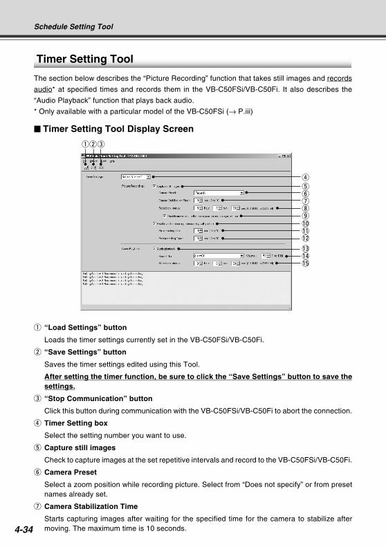
4-34
Timer Setting Tool
The section below describes the “Picture Recording” function that takes still images and records
audio* at specified times and records them in the VB-C50FSi/VB-C50Fi. It also describes the
“Audio Playback” function that plays back audio.
* Only available with a particular model of the VB-C50FSi (→ P.iii)
Timer Setting Tool Display Screen
q “Load Settings” button
Loads the timer settings currently set in the VB-C50FSi/VB-C50Fi.
w “Save Settings” button
Saves the timer settings edited using this Tool.
After setting the timer function, be sure to click the “Save Settings” button to save thesettings.
e “Stop Communication” button
Click this button during communication with the VB-C50FSi/VB-C50Fi to abort the connection.
r Timer Setting box
Select the setting number you want to use.
t Capture still images
Check to capture images at the set repetitive intervals and record to the VB-C50FSi/VB-C50Fi.
y Camera Preset
Select a zoom position while recording picture. Select from “Does not specify” or from presetnames already set.
u Camera Stabilization Time
Starts capturing images after waiting for the specified time for the camera to stabilize aftermoving. The maximum time is 10 seconds.
Schedule Setting Tool
qwe
r
tyuio!0!1!2
!3!4!5
COPY
4-35
VB
Ad
min
istration
Too
lsSchedule Setting Tool
i Repetition Interval
Sets the interval between repeated image recording. Repetition Interval can be set to a maximumof 23 hours, 59 minutes and 59 seconds. If you set Repetition Interval to 0, a still image is onlyrecorded once at the start of the scheduled time.
o Disable movement to the home position and auto preset tour
Check to deactivate movement to home position and Preset Tour during picture recording.You can only enter a tick if a preset is specified in “Camera Preset” and “Repetition Interval” isset to more than 30 seconds.
!0 Enable audio recording concurrently with picture*
Check to record audio at a set time. Set up the “Pre-recording Time” and “Post-recordingTime” below.* Only available with a particular model of the VB-C50FSi (→ P.iii)
!1 Pre-recording Time*
Records audio for the specified time before picture recording begins. Set a duration between 0and 10 seconds.* Only available with a particular model of the VB-C50FSi (→ P.iii)
!2 Post-recording Time*
Records audio for the specified time after picture recording ends. Set a duration between 0and 30 seconds.* Only available with a particular model of the VB-C50FSi (→ P.iii)
!3 Audio playback (VB-C50FSi only)
Check for playback of audio at the set repetition interval. Set up the “Sound Clip”, “Volume”and “Repetition Interval” below.
!4 Sound Clip and Volume (VB-C50FSi only)
Set the audio for playback. Select from the registered playback audio names. Set the volumeat which the audio is to be played back, between 1 and 100.
!5 Repetition Interval (VB-C50FSi only)
Set the interval between playback of audio. You can set an interval to a maximum of 23 hours,59 minutes and 59 seconds. If you set Repetition Interval to 0, the audio will play back onlyonce at the start of the scheduled time.
Note
When recording consecutive audio files, set the Pre-recording Time and Post-
recording Time so that the total duration is longer than Repetition Interval (so that
the next recording begins before the recording process ends). The consecutive
recorded audio files are created in 120-second segments.
Specify the audio recording volume, noise canceller and slope filter settings on the
Audio Server settings page (→ P. 3-19).
You cannot set 0 seconds for both the Pre-recording Time and Post-recording
Time.
COPY
4-36
Setting Up Picture Recording
To Make Settings...
1. With the Schedule Setting Tool, open the Timer Setting Tool.
In the Service tab of the Schedule Setting screen for a Normal or Special Schedule, check“Timer”, select a setting number and click the “Detail” button (→ P.4-33) .
2. Check “Capture still images” and set “Camera Preset”, “Camera StabilizationTime”, “Repetition Interval”, “Disable movement to the home position andauto preset tour”, “Enable audio recording concurrently with picture”, “Pre-recording Time” and “Post-recording Time”*.* Only available with a particular model of the VB-C50FSi (→ P.iii)
3. Click the “Save Settings” button to save the settings and close the TimerSetting screen.
Tip
Sample sound files are contained on the CD-ROM.
For registering and deleting audio files, see “Audio Playback Settings dialog box”
(→ P. 4-57).
Setting Up Audio Playback (VB-C50FSi only)
To Make Settings...
1. With the Schedule Setting Tool, open the Timer Setting Tool.
In the Service tab of the Normal or Special Schedule Setting screen, check “Timer”, select asetting number and click the “Detail” button (→ P.4-33).
2. Check “Audio playback” and set “Sound Clip”, “Volume” and “Repetition Interval”.
3. Click the “Save Settings” button to save the settings and close the TimerSetting screen.
Schedule Setting Tool
COPY
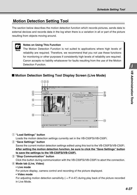
4-37
VB
Ad
min
istration
Too
ls
Motion Detection Setting Tool
The section below describes the motion detection function which records pictures, sends data to
external devices and records data in the log when there is a variation in all or part of the picture
resulting from objects moving around.
q “Load Settings” buttonLoads the motion detection settings currently set in the VB-C50FSi/VB-C50Fi.
w “Save Settings” buttonSaves the current motion detection settings edited using this tool to the VB-C50FSi/VB-C50Fi.After setting the motion detection function, be sure to click the “Save Settings” buttonto save the settings to the VB-C50FSi/VB-C50Fi.
e “Stop Communication” buttonClick this button during communication with the VB-C50FSi/VB-C50Fi to abort the connection.
r Mode tab (Live, Video)• Live modeFor picture display, camera control and recording of the picture displayed.• Video modeFor adjusting motion detection sensitivity (→ P.4-47) during play back of the picture recordedin Live Mode.
Note
Notes on Using This Function
The Motion Detection Function is not suited to applications where high levels of
reliability are required. Therefore, we recommend that you not use these functions
for monitoring or other purposes if consistently high levels of reliability are required.
Canon accepts no liability whatsoever for faults resulting from the use of the Motion
Detection Function.
o!0
i
u
y
tr
qwe
Schedule Setting Tool
Motion Detection Setting Tool Display Screen (Live Mode)
!1COPY
4-38
t Camera Selection boxFor selecting a camera.
y ViewerFor picture display and camera control in the same way as a normal viewer.
u Motion detection area frameDisplays with a dotted frame the area within which motion is to be detected. The frame can bereshaped and moved by dragging the mouse.
i “Rec. Start” buttonStarts recording of the picture.
o Setting number selection boxSelect the number of the setting you want to use.
!0 Settings tabs (Camera, Area, Recording, Output, Audio/Tracking)
• Camera tabFor setting the frame rate and camera positions (→ P.4-40).
• Area tabFor selecting the area within which motion is to be detected and the sensitivity, area ratio andduration for each area (→ P.4-41).
• Recording tabFor setting the duration of picture and audio recording* when the camera detects motion (ONevent) or when the camera can no longer detect motion (OFF event), and for setting the recordinginterval (→ P.4-43).* Only available with a particular model of the VB-C50FSi (→ P.iii)
• Output tabFor setting output of data to an external device (→ P.4-44).
• Audio/Tracking tabSets Audio Playback (VB-C50FSi only) (→ P.4-44).
!1 Display motion detection status of the serverCheck to display the results of motion detection by the server. You can check whether or notthe settings are activated in the device (→ P.4-45).
Schedule Setting Tool
COPY
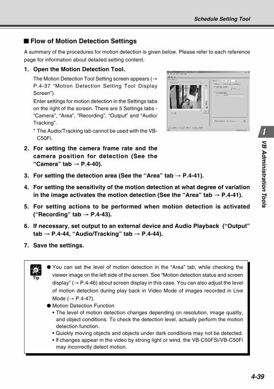
4-39
VB
Ad
min
istration
Too
ls
Flow of Motion Detection Settings
A summary of the procedures for motion detection is given below. Please refer to each reference
page for information about detailed setting content.
1. Open the Motion Detection Tool.
The Motion Detection Tool Setting screen appears (→P.4-37 “Motion Detection Setting Tool DisplayScreen”).
Enter settings for motion detection in the Settings tabson the right of the screen. There are 5 Settings tabs -“Camera”, “Area”, “Recording”, “Output” and “Audio/Tracking”.
* The Audio/Tracking tab cannot be used with the VB-C50Fi.
2. For setting the camera frame rate and thecamera position for detection (See the“Camera” tab → P.4-40).
3. For setting the detection area (See the “Area” tab → P.4-41).
4. For setting the sensitivity of the motion detection at what degree of variationin the image activates the motion detection (See the “Area” tab → P.4-41).
5. For setting actions to be performed when motion detection is activated(“Recording” tab → P.4-43).
6. If necessary, set output to an external device and Audio Playback (“Output”tab → P.4-44, “Audio/Tracking” tab → P.4-44).
7. Save the settings.
Tip
You can set the level of motion detection in the “Area” tab, while checking the
viewer image on the left side of the screen. See “Motion detection status and screen
display” (→ P.4-46) about screen display in this case. You can also adjust the level
of motion detection during play back in Video Mode of images recorded in Live
Mode (→ P.4-47). Motion Detection Function
• The level of motion detection changes depending on resolution, image quality,and object conditions. To check the detection level, actually perform the motiondetection function.
• Quickly moving objects and objects under dark conditions may not be detected.• If changes appear in the video by strong light or wind, the VB-C50FSi/VB-C50Fi
may incorrectly detect motion.
Schedule Setting Tool
COPY
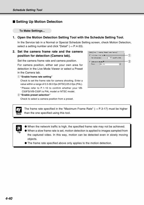
4-40
Setting Up Motion Detection
To Make Settings...
1. Open the Motion Detection Setting Tool with the Schedule Setting Tool.
In the Service tab in a Normal or Special Schedule Setting screen, check Motion Detection,select a setting number and click “Detail” (→ P.4-33).
2. Set the camera frame rate and the cameraposition for detection (Camera tab).
Set the camera frame rate and camera position.
For camera position, either set your own area fordetection in the Live Mode Viewer or select a Presetin the Camera tab.
q “Enable frame rate setting”
Check to set the frame rate for camera shooting. Enter avalue within a range of 0.5-30.0 fps (NTSC)/25.0 fps (PAL).
* Please refer to P.1-10 to confirm whether your VB-C50FSi/VB-C50Fi is PAL model or NTSC model.
w “Enable preset selection”
Check to select a camera position from a preset.
Note
The frame rate specified in the “Maximum Frame Rate” (→ P.3-17) must be higher
than the one specified using this tool.
q
w
Tip
When the network traffic is high, the specified frame rate may not be achieved.
When a slow frame rate is set, motion detection is applied to images sampled from
the captured video. In this way, motion can be detected even in slowly moving
objects.
The frame rate specified above only applies to the motion detection.
Schedule Setting Tool
COPY
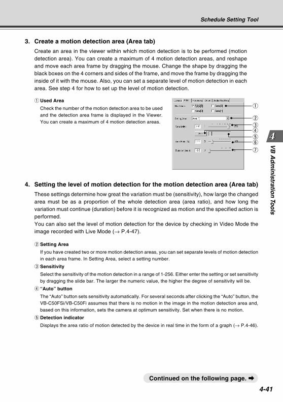
4-41
VB
Ad
min
istration
Too
ls
q Used Area
Check the number of the motion detection area to be usedand the detection area frame is displayed in the Viewer.You can create a maximum of 4 motion detection areas.
Schedule Setting Tool
3. Create a motion detection area (Area tab)
Create an area in the viewer within which motion detection is to be performed (motiondetection area). You can create a maximum of 4 motion detection areas, and reshapeand move each area frame by dragging the mouse. Change the shape by dragging theblack boxes on the 4 corners and sides of the frame, and move the frame by dragging theinside of it with the mouse. Also, you can set a separate level of motion detection in eacharea. See step 4 for how to set up the level of motion detection.
4. Setting the level of motion detection for the motion detection area (Area tab)
These settings determine how great the variation must be (sensitivity), how large the changedarea must be as a proportion of the whole detection area (area ratio), and how long thevariation must continue (duration) before it is recognized as motion and the specified action isperformed.You can also set the level of motion detection for the device by checking in Video Mode theimage recorded with Live Mode (→ P.4-47).
w Setting Area
If you have created two or more motion detection areas, you can set separate levels of motion detectionin each area frame. In Setting Area, select a setting number.
e Sensitivity
Select the sensitivity of the motion detection in a range of 1-256. Either enter the setting or set sensitivityby dragging the slide bar. The larger the numeric value, the higher the degree of sensitivity will be.
r “Auto” button
The “Auto” button sets sensitivity automatically. For several seconds after clicking the “Auto” button, theVB-C50FSi/VB-C50Fi assumes that there is no motion in the image in the motion detection area and,based on this information, sets the camera at optimum sensitivity. Set when there is no motion.
t Detection indicator
Displays the area ratio of motion detected by the device in real time in the form of a graph (→ P.4-46).
Continued on the following page. a
w
y
u
q
ert
COPY
4-42
Tip
If Sensitivity is set at a low level, the device does not recognize the motion even
during great variations in the image inside the motion detection area frame. Also, if
the area ratio and duration of the motion in the part of the image where motion
occurred in the area frame do not reach the set values, the device does not perform
detection and the specified actions such as picture recording are not performed.
You can select a setting area by clicking the motion detection area frame in the
Viewer you want to specify. The selected motion detection area frame is displayed
as a blue frame.
If you set the setting area to “Not specified”, the results of detection in all the
motion detection areas you have created are displayed in each area frame. Also,
even if you click an area which does not fall within any of the motion detection area
frames in the Viewer, the setting area is set as “Not specified”.
Schedule Setting Tool
y Area Ratio
When the proportion of the area in which the device has detected motion (displayed in a red or yellowrectangle) has exceeded the specified value for the area of the selected detection area frame (blueframe), the device detects motion and performs the specified picture recording etc. (However, even ifthe area ratio value is exceeded, the device does not detect motion unless the number of secondsspecified in Duration has passed). Set within a range of 0-100%, by either entering a numeric value orby dragging the slide bar.
u Duration
When the situation where the motion has exceeded the area ratio continuous for more than the durationtime, the device detects motion and performs picture recording etc. Set within a range of 0-5 seconds,by either entering a numeric value or by dragging the slide bar.
COPY
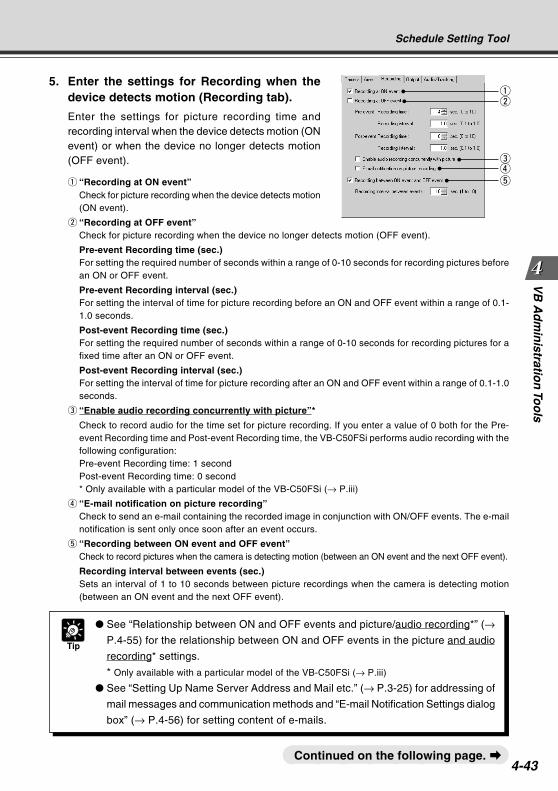
4-43
VB
Ad
min
istration
Too
ls
Tip
See “Relationship between ON and OFF events and picture/audio recording*” (→P.4-55) for the relationship between ON and OFF events in the picture and audio
recording* settings.
* Only available with a particular model of the VB-C50FSi (→ P.iii)
See “Setting Up Name Server Address and Mail etc.” (→ P.3-25) for addressing of
mail messages and communication methods and “E-mail Notification Settings dialog
box” (→ P.4-56) for setting content of e-mails.
Continued on the following page. a
Schedule Setting Tool
5. Enter the settings for Recording when thedevice detects motion (Recording tab).
Enter the settings for picture recording time andrecording interval when the device detects motion (ONevent) or when the device no longer detects motion(OFF event).
q “Recording at ON event”Check for picture recording when the device detects motion(ON event).
w “Recording at OFF event”Check for picture recording when the device no longer detects motion (OFF event).
Pre-event Recording time (sec.)For setting the required number of seconds within a range of 0-10 seconds for recording pictures beforean ON or OFF event.
Pre-event Recording interval (sec.)For setting the interval of time for picture recording before an ON and OFF event within a range of 0.1-1.0 seconds.
Post-event Recording time (sec.)For setting the required number of seconds within a range of 0-10 seconds for recording pictures for afixed time after an ON or OFF event.
Post-event Recording interval (sec.)For setting the interval of time for picture recording after an ON and OFF event within a range of 0.1-1.0seconds.
e “Enable audio recording concurrently with picture”*
Check to record audio for the time set for picture recording. If you enter a value of 0 both for the Pre-event Recording time and Post-event Recording time, the VB-C50FSi performs audio recording with thefollowing configuration:Pre-event Recording time: 1 secondPost-event Recording time: 0 second* Only available with a particular model of the VB-C50FSi (→ P.iii)
r “E-mail notification on picture recording”Check to send an e-mail containing the recorded image in conjunction with ON/OFF events. The e-mailnotification is sent only once soon after an event occurs.
t “Recording between ON event and OFF event”Check to record pictures when the camera is detecting motion (between an ON event and the next OFF event).
Recording interval between events (sec.)Sets an interval of 1 to 10 seconds between picture recordings when the camera is detecting motion(between an ON event and the next OFF event).
qw
ert
COPY
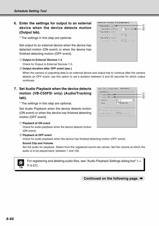
4-44
6. Enter the settings for output to an externaldevice when the device detects motion(Output tab).
* The settings in this step are optional.
Set output to an external device when the device hasdetected motion (ON event) or when the device hasfinished detecting motion (OFF event).
q Output to External Devices 1-3
Check for Output to External Devices 1-3.
w Output duration after OFF event (sec.)
When the camera is outputting data to an external device and output has to continue after the cameradetects an OFF event, use this option to set a duration between 0 and 20 seconds for which outputcontinues.
qw
Schedule Setting Tool
Continued on the following page. a
7. Set Audio Playback when the device detectsmotion (VB-C50FSi only) (Audio/Trackingtab).
* The settings in this step are optional.
Set Audio Playback when the device detects motion(ON event) or when the device has finished detectingmotion (OFF event).
q Playback at ON eventCheck for audio playback when the device detects motion(ON event).
w Playback at OFF eventCheck for audio playback when the device has finished detecting motion (OFF event).
Sound Clip and VolumeSet the audio for playback. Select from the registered sound clip names. Set the volume at which theaudio is to be played back, between 1 and 100.
Tip
For registering and deleting audio files, see “Audio Playback Settings dialog box” (→P.4-57).
qw
COPY
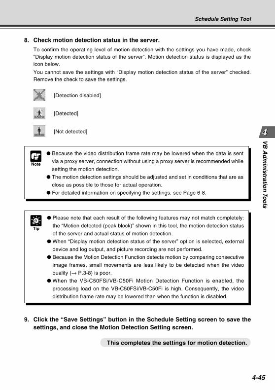
4-45
VB
Ad
min
istration
Too
ls
Note
Because the video distribution frame rate may be lowered when the data is sent
via a proxy server, connection without using a proxy server is recommended while
setting the motion detection.
The motion detection settings should be adjusted and set in conditions that are as
close as possible to those for actual operation.
For detailed information on specifying the settings, see Page 6-8.
Tip
Please note that each result of the following features may not match completely:
the “Motion detected (peak block)” shown in this tool, the motion detection status
of the server and actual status of motion detection.
When “Display motion detection status of the server” option is selected, external
device and log output, and picture recording are not performed.
Because the Motion Detection Function detects motion by comparing consecutive
image frames, small movements are less likely to be detected when the video
quality (→ P.3-8) is poor.
When the VB-C50FSi/VB-C50Fi Motion Detection Function is enabled, the
processing load on the VB-C50FSi/VB-C50Fi is high. Consequently, the video
distribution frame rate may be lowered than when the function is disabled.
This completes the settings for motion detection.
Schedule Setting Tool
8. Check motion detection status in the server.
To confirm the operating level of motion detection with the settings you have made, check“Display motion detection status of the server”. Motion detection status is displayed as theicon below.
You cannot save the settings with “Display motion detection status of the server” checked.Remove the check to save the settings.
[Detection disabled]
[Detected]
[Not detected]
9. Click the “Save Settings” button in the Schedule Setting screen to save thesettings, and close the Motion Detection Setting screen.
COPY
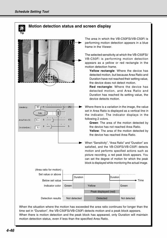
4-46
Tip
Motion detection status and screen display
The area in which the VB-C50FSi/VB-C50Fi isperforming motion detection appears in a blueframe in the Viewer.
The selected sensitivity at which the VB-C50FSi/VB-C50Fi is performing motion detectionappears as a yellow or red rectangle in themotion detection frame.
Yellow rectangle: Where the device hasdetected motion, but because Area Ratio andDuration have not reached their setting value,the device does not detect motion.Red rectangle: Where the device hasdetected motion, and Area Ratio andDuration has reached its setting value, thedevice detects motion.
Where there is a variation in the image, the valueset in Area Ratio is displayed as a vertical line inthe indicator. The indicator displays in thefollowing 2 colors.
Green: The area of the motion detected bythe device has not reached Area Ratio.Yellow: The area of the motion detected bythe device has reached Area Ratio.
When “Sensitivity”, “Area Ratio” and “Duration” aresatisfied, and the VB-C50FSi/VB-C50Fi detectsmotion and performs specified actions such aspicture recording, a red peak block appears. Youcan set the degree of motion for which the peakblock is displayed while monitoring the actual image.
Set value or above
Below set value
Indicator color Green Yellow
Peak displayed (red)
Green
Not detected Detected Not detected
(Area ratio for motion)
Duration DurationTime
Detection results
Schedule Setting Tool
When the situation where the motion has exceeded the area ratio continues for longer than thetime set in “Duration”, the VB-C50FSi/VB-C50Fi detects motion and a peak block appears.When there is motion detection and the peak block has appeared, only Duration will maintainmotion detection status, even if less than the specified Area Ratio.
COPY
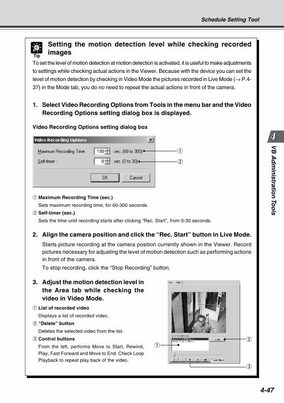
4-47
VB
Ad
min
istration
Too
ls
q
w
Tip
Setting the motion detection level while checking recordedimages
To set the level of motion detection at motion detection is activated, it is useful to make adjustments
to settings while checking actual actions in the Viewer. Because with the device you can set the
level of motion detection by checking in Video Mode the pictures recorded in Live Mode (→ P.4-
37) in the Mode tab, you do no need to repeat the actual actions in front of the camera.
1. Select Video Recording Options from Tools in the menu bar and the VideoRecording Options setting dialog box is displayed.
Video Recording Options setting dialog box
qw
Schedule Setting Tool
q Maximum Recording Time (sec.)
Sets maximum recording time, for 60-300 seconds.
w Self-timer (sec.)
Sets the time until recording starts after clicking “Rec. Start”, from 0-30 seconds.
2. Align the camera position and click the “Rec. Start” button in Live Mode.
Starts picture recording at the camera position currently shown in the Viewer. Recordpictures necessary for adjusting the level of motion detection such as performing actionsin front of the camera.
To stop recording, click the “Stop Recording” button.
3. Adjust the motion detection level inthe Area tab while checking thevideo in Video Mode.
q List of recorded video
Displays a list of recorded video.
w “Delete” button
Deletes the selected video from the list.
e Control buttons
From the left, performs Move to Start, Rewind,Play, Fast Forward and Move to End. Check LoopPlayback to repeat play back of the video.
e
COPY
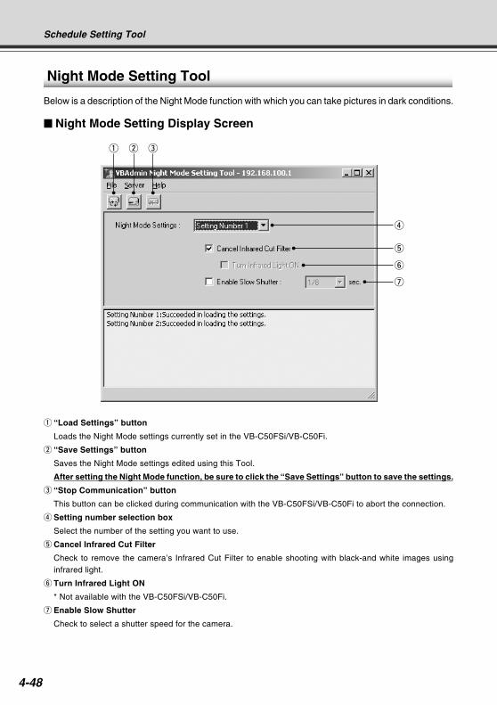
4-48
q w e
r
t
y
u
Night Mode Setting Tool
Below is a description of the Night Mode function with which you can take pictures in dark conditions.
Night Mode Setting Display Screen
q “Load Settings” button
Loads the Night Mode settings currently set in the VB-C50FSi/VB-C50Fi.
w “Save Settings” button
Saves the Night Mode settings edited using this Tool.
After setting the Night Mode function, be sure to click the “Save Settings” button to save the settings.
e “Stop Communication” button
This button can be clicked during communication with the VB-C50FSi/VB-C50Fi to abort the connection.
r Setting number selection box
Select the number of the setting you want to use.
t Cancel Infrared Cut Filter
Check to remove the camera’s Infrared Cut Filter to enable shooting with black-and white images usinginfrared light.
y Turn Infrared Light ON
* Not available with the VB-C50FSi/VB-C50Fi.
u Enable Slow Shutter
Check to select a shutter speed for the camera.
Schedule Setting Tool
COPY
4-49
VB
Ad
min
istration
Too
ls
Setting Up Night Mode
To Make Settings...
1. With the Schedule Setting Tool, open the Night Mode Setting Tool.
In the Service tab of the Schedule Setting screen for a Normal or Special Schedule, checkNight Mode, select a setting number and click the “Detail” button (→ P.4-33), or click the“Night mode setting tool” button on the toolbar.
If you have opened the Night Mode Tool from the toolbar, select a setting number from thesetting number selection box in the Night Mode Setting screen.
2. Check Cancel Infrared Cut Filter and/or Enable Slow Shutter as required.
3. Click the “Save Settings” button to save the settings and close the Night ModeSetting screen.
Tip
In Night Mode, focusing with Auto Focus may be difficult or may appear to be out
of focus.
“Auto (for domes)” and “Fixed at infinity” configured with Focus Mode (→ P.3-9) is
not available if you check the “Cancel Infrared Cut Filter”.
Schedule Setting Tool
Note
If you have selected “Enable Slow Shutter”, the exposure will be manual, and the
aperture and gain will be at maximum.
Change the shutter speed and adjust brightness according to your operating
environment and photographic subject.
If you specify a shutter speed of 1/30 seconds or slower for NTSC, or 1/25 seconds
or slower for PAL, auto focus will not operate.
COPY
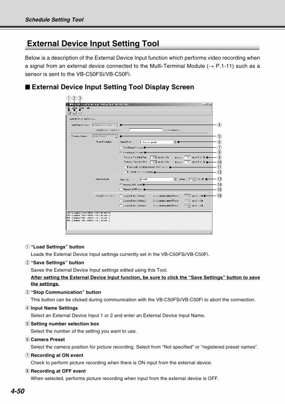
4-50
External Device Input Setting Tool
Below is a description of the External Device Input function which performs video recording when
a signal from an external device connected to the Multi-Terminal Module (→ P.1-11) such as a
sensor is sent to the VB-C50FSi/VB-C50Fi.
External Device Input Setting Tool Display Screen
q “Load Settings” button
Loads the External Device Input settings currently set in the VB-C50FSi/VB-C50Fi.
w “Save Settings” button
Saves the External Device Input settings edited using this Tool.
After setting the External Device Input function, be sure to click the “Save Settings” button to savethe settings.
e “Stop Communication” button
This button can be clicked during communication with the VB-C50FSi/VB-C50Fi to abort the connection.
r Input Name Settings
Select an External Device Input 1 or 2 and enter an External Device Input Name.
t Setting number selection box
Select the number of the setting you want to use.
y Camera Preset
Select the camera position for picture recording. Select from “Not specified” or “registered preset names”.
u Recording at ON event
Check to perform picture recording when there is ON input from the external device.
i Recording at OFF event
When selected, performs picture recording when input from the external device is OFF.
Schedule Setting Tool
qwe
r
tyui
!2
o!0
!3
!5
!6
!4
!1
COPY
4-51
VB
Ad
min
istration
Too
ls
o Pre-event Recording Time (sec.) and Interval
Enter the required number of seconds, within a range of 0-10 seconds for picture recording before an ONand/or OFF event. Also enter an interval for performing picture recording, within a range of 0.1-1.0 seconds.
!0 Post-event Recording Time (sec.) and IntervalEnter the required number of seconds, within a range of 0-10 seconds for picture recording following an ONand/or OFF event. Also enter an interval for performing picture recording, within a range of 0.1-1.0 seconds.
!1 Enable audio recording concurrently with picture*Check to record audio for the time set for picture recording. If you enter a value of 0 both for the Pre-eventRecording time and Post-event Recording time, the VB-C50FSi performs audio recording with the followingconfiguration:Pre-event Recording time: 1 secondPost-event Recording time: 0 second* Only available with a particular model of the VB-C50FSi (→ P.iii)
!2 E-mail notification on recordingCheck to send an e-mail of the recorded picture.
!3 Sound Clip and Volume (VB-C50FSi only)Set the audio for playback. Select from the registered sound clip names. Set the volume at which the audiois to be played back, between 1 and 100.
!4 Playback at ON event (VB-C50FSi only)Check for audio playback when there is ON input from an external device.
!5 Playback at OFF event (VB-C50FSi only)Check for audio playback when input from an external device is OFF.
!6 Output to External Device 1-3 and Output duration after OFF event (sec.)Check to perform output to an external device at OFF event. Enter a time for performing output in the rangeof 0-30 seconds.
Setting Up External Device Input
To Make Settings...
1. With the Schedule Setting Tool, open the External Device Input Setting Tool.
In the Service tab of the Schedule Setting screen for a Normal or Special Schedule, checkInput 1 or Input 2 in External Device Input, select a setting number and click the “Detail” button(→ P.4-33), or click the “External input device setting tool” button on the toolbar.
If you have opened the External Device Input Tool from the toolbar, select an External DeviceInput Name and setting number in the External Device Input Setting screen.
2. Perform picture recording operations.
Check either Recording at ON event or Recording at OFF event, and select a Camera Preset.
Also, enter the required number of seconds and the interval for picture recording before orafter an ON or OFF event.
If you check “Enable audio recording concurrently with picture”, audio is recorded for the timeset for picture recording*.* Only available with a particular model of the VB-C50FSi (→ P.iii)
If you check “E-mail notification on recording” you can send recorded pictures as e-mail whenan event occurs. The e-mail notification is sent only once soon after an event occurs.
Schedule Setting Tool
COPY
4-52
Schedule Setting Tool
Tip
See “Relationship between ON and OFF events and picture/audio recording*” (→P.4-55) for the relationship between ON and OFF events in the picture and audio
recording* settings.
* Only available with a particular model of the VB-C50FSi (→ P.iii)
3. Specify the Audio Playback operation settings.Check “Playback at ON event” or “Playback at OFF event” and select the playback sound clipname and volume.
Tip
For registering and deleting audio files, see “Audio Playback Settings dialog box”
(→ P.4-57).
4. Set external device output operations.Tick one of “Output to External Device 1” to “Output to External Device 3” options and specifythe “Output duration after OFF event” setting.
5. Click the “Save Settings” button to save the settings and close the ExternalDevice Input Setting screen.
Tip
See “Setting Up Name Server Address and Mail etc.” (→ P.3-25) for the addresses of
mail messages and communication methods and “E-mail Notification Settings dialog
box” (→ P.4-56) for setting content of mail messages.
COPY
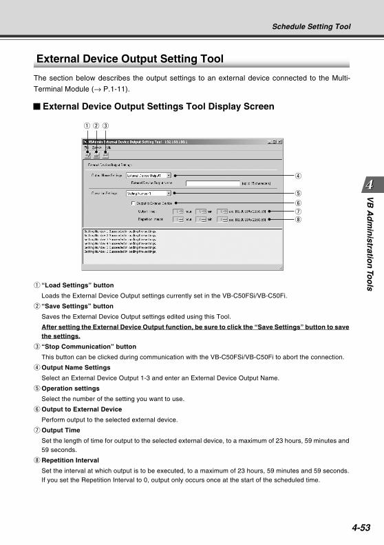
4-53
VB
Ad
min
istration
Too
ls
External Device Output Setting Tool
The section below describes the output settings to an external device connected to the Multi-
Terminal Module (→ P.1-11).
External Device Output Settings Tool Display Screen
q “Load Settings” button
Loads the External Device Output settings currently set in the VB-C50FSi/VB-C50Fi.
w “Save Settings” button
Saves the External Device Output settings edited using this Tool.
After setting the External Device Output function, be sure to click the “Save Settings” button to savethe settings.
e “Stop Communication” button
This button can be clicked during communication with the VB-C50FSi/VB-C50Fi to abort the connection.
r Output Name Settings
Select an External Device Output 1-3 and enter an External Device Output Name.
t Operation settings
Select the number of the setting you want to use.
y Output to External Device
Perform output to the selected external device.
u Output Time
Set the length of time for output to the selected external device, to a maximum of 23 hours, 59 minutes and59 seconds.
i Repetition Interval
Set the interval at which output is to be executed, to a maximum of 23 hours, 59 minutes and 59 seconds.If you set the Repetition Interval to 0, output only occurs once at the start of the scheduled time.
Schedule Setting Tool
q w e
r
t
y
u
i
COPY
4-54
Setting Up External Device Output
To Make Settings...
1. With the Schedule Setting Tool, open the External Device Output Setting Tool.
In the Service tab of the Schedule Setting screen for a Normal or Special Schedule, checkOutput1-3 in External Device Output, select a setting number and click the “Detail” button(→ P.4-33), or click the “External device output setting tool” button on the toolbar.
If you have opened the External Device Output Tool from the toolbar, select an ExternalDevice Output Name and setting number in the External Device Output Setting screen.
2. Check Output to External Device and set Output Time and Repetition Interval.
3. Click the “Save Settings” button to save the settings and close the ExternalDevice Output Setting screen.
Tip
If you set Output Time at more than Repetition Interval, output continues without
interruption.
Schedule Setting Tool
COPY
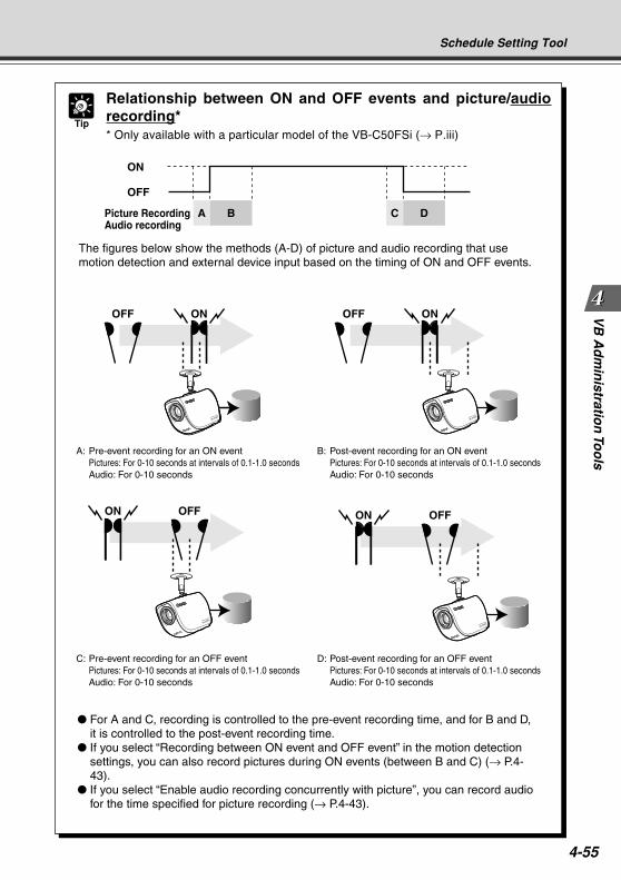
4-55
VB
Ad
min
istration
Too
lsSchedule Setting Tool
Tip
Relationship between ON and OFF events and picture/audiorecording** Only available with a particular model of the VB-C50FSi (→ P.iii)
ONOFF ONOFF
ON
OFF
Picture RecordingAudio recording
A B C D
ON OFF
The figures below show the methods (A-D) of picture and audio recording that use motion detection and external device input based on the timing of ON and OFF events.
For A and C, recording is controlled to the pre-event recording time, and for B and D, it is controlled to the post-event recording time.
If you select “Recording between ON event and OFF event” in the motion detection settings, you can also record pictures during ON events (between B and C) (→ P.4-43).
If you select “Enable audio recording concurrently with picture”, you can record audio for the time specified for picture recording (→ P.4-43).
A: Pre-event recording for an ON eventPictures: For 0-10 seconds at intervals of 0.1-1.0 secondsAudio: For 0-10 seconds
B: Post-event recording for an ON eventPictures: For 0-10 seconds at intervals of 0.1-1.0 secondsAudio: For 0-10 seconds
ON OFF
D: Post-event recording for an OFF eventPictures: For 0-10 seconds at intervals of 0.1-1.0 secondsAudio: For 0-10 seconds
C: Pre-event recording for an OFF eventPictures: For 0-10 seconds at intervals of 0.1-1.0 secondsAudio: For 0-10 seconds
COPY
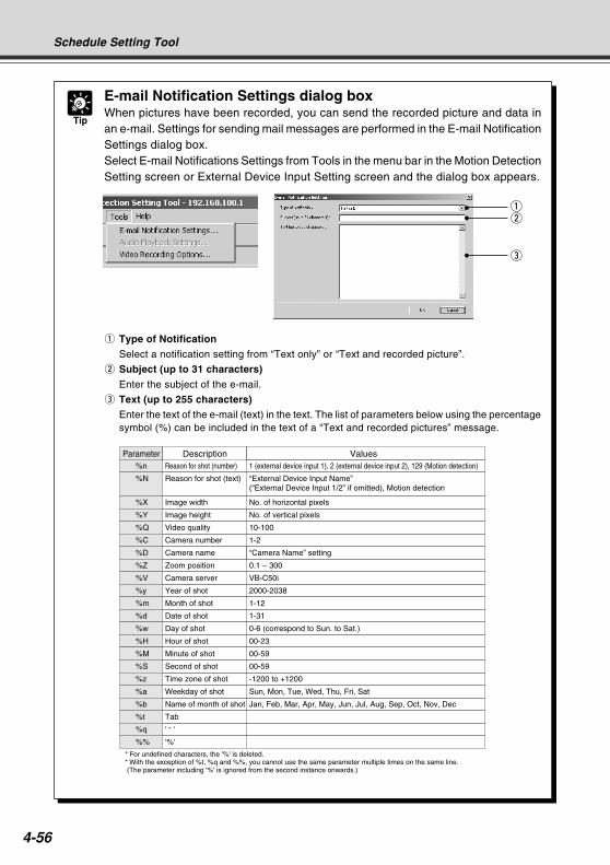
4-56
Tip
E-mail Notification Settings dialog boxWhen pictures have been recorded, you can send the recorded picture and data inan e-mail. Settings for sending mail messages are performed in the E-mail NotificationSettings dialog box.Select E-mail Notifications Settings from Tools in the menu bar in the Motion DetectionSetting screen or External Device Input Setting screen and the dialog box appears.
q Type of NotificationSelect a notification setting from “Text only” or “Text and recorded picture”.
w Subject (up to 31 characters)
Enter the subject of the e-mail.
e Text (up to 255 characters)Enter the text of the e-mail (text) in the text. The list of parameters below using the percentagesymbol (%) can be included in the text of a “Text and recorded pictures” message.
Schedule Setting Tool
Reason for shot (number) 1 (external device input 1), 2 (external device input 2), 129 (Motion detection)%n
Reason for shot (text) “External Device Input Name”(“External Device Input 1/2” if omitted), Motion detection
%N
Parameter Description Values
* For undefined characters, the '%' is deleted.* With the exception of %t, %q and %%, you cannot use the same parameter multiple times on the same line. (The parameter including '%' is ignored from the second instance onwards.)
Image width No. of horizontal pixels%X
Image height No. of vertical pixels%Y
Video quality 10-100%Q
Camera number 1-2%C
Camera name “Camera Name” setting%D
Zoom position 0.1 ~ 300%Z
Camera server VB-C50i%V
Year of shot 2000-2038%y
Month of shot 1-12%m
Date of shot 1-31%d
Day of shot 0-6 (correspond to Sun. to Sat.)%w
Hour of shot 00-23%H
Minute of shot 00-59%M
Second of shot 00-59%S
Time zone of shot -1200 to +1200%z
Weekday of shot Sun, Mon, Tue, Wed, Thu, Fri, Sat%a
Name of month of shot Jan, Feb, Mar, Apr, May, Jun, Jul, Aug, Sep, Oct, Nov, Dec%b
Tab%t
'%'%%
' ” '%q
qw
e
COPY
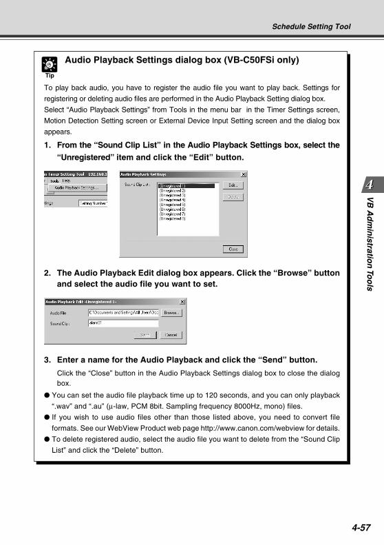
4-57
VB
Ad
min
istration
Too
ls
Tip
Audio Playback Settings dialog box (VB-C50FSi only)
To play back audio, you have to register the audio file you want to play back. Settings for
registering or deleting audio files are performed in the Audio Playback Setting dialog box.
Select “Audio Playback Settings” from Tools in the menu bar in the Timer Settings screen,
Motion Detection Setting screen or External Device Input Setting screen and the dialog box
appears.
1. From the “Sound Clip List” in the Audio Playback Settings box, select the
2. The Audio Playback Edit dialog box appears. Click the “Browse” buttonand select the audio file you want to set.
“Unregistered” item and click the “Edit” button.
3. Enter a name for the Audio Playback and click the “Send” button.
Click the “Close” button in the Audio Playback Settings dialog box to close the dialogbox.
You can set the audio file playback time up to 120 seconds, and you can only playback
“.wav” and “.au” (µ-law, PCM 8bit. Sampling frequency 8000Hz, mono) files.
If you wish to use audio files other than those listed above, you need to convert file
formats. See our WebView Product web page http://www.canon.com/webview for details.
To delete registered audio, select the audio file you want to delete from the “Sound Clip
List” and click the “Delete” button.
Schedule Setting Tool
COPY
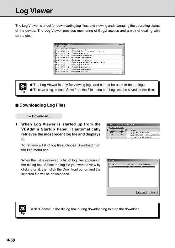
4-58
The Log Viewer is a tool for downloading log files, and viewing and managing the operating status
of the device. The Log Viewer provides monitoring of illegal access and a way of dealing with
errors etc.
Downloading Log Files
To Download...
1. When Log Viewer is started up from theVBAdmin Startup Panel, it automaticallyretrieves the most recent log file and displaysit.
To retrieve a list of log files, choose Download fromthe File menu bar.
When the list is retrieved, a list of log files appears inthe dialog box. Select the log file you want to view byclicking on it, then click the Download button and theselected file will be downloaded.
Log Viewer
Tip
The Log Viewer is only for viewing logs and cannot be used to delete logs.
To save a log, choose Save from the File menu bar. Logs can be saved as text files.
TipClick “Cancel” in the dialog box during downloading to stop the download.
COPY
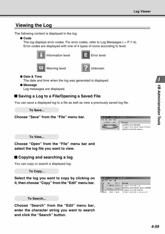
4-59
VB
Ad
min
istration
Too
lsLog Viewer
Viewing the Log
The following content is displayed in the log.
CodeThe log displays error codes. For error codes, refer to Log Messages (→ P.7-4).Error codes are displayed with one of 4 types of icons according to level.
Information level Error level
Warning level Unknown
Date & TimeThe date and time when the log was generated is displayed.
MessageLog messages are displayed.
Saving a Log to a File/Opening a Saved File
You can save a displayed log to a file as well as view a previously saved log file.
To Save...
Choose “Save” from the “File” menu bar.
To View...
Choose “Open” from the “File” menu bar andselect the log file you want to view.
Copying and searching a log
You can copy or search a displayed log.
To Copy...
Select the log you want to copy by clicking onit, then choose “Copy” from the “Edit” menu bar.
To Search...
Choose “Search” from the “Edit” menu bar,enter the character string you want to searchand click the “Search” button.
COPY
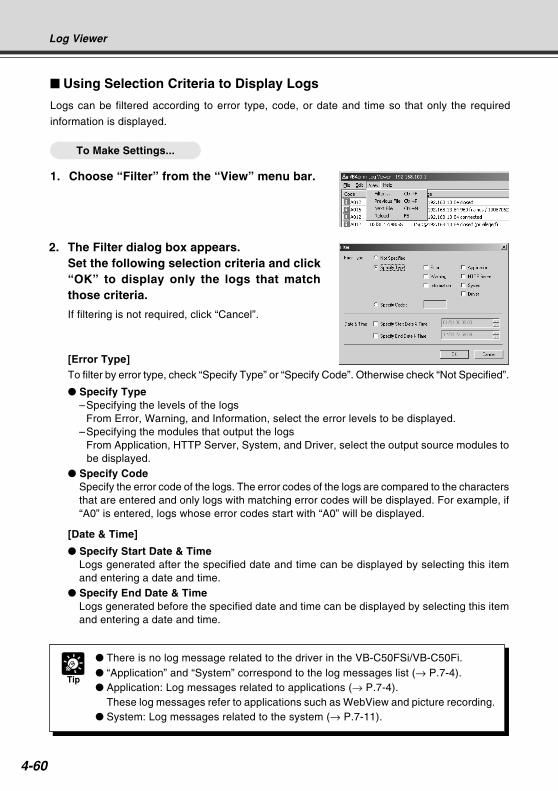
4-60
Using Selection Criteria to Display Logs
Logs can be filtered according to error type, code, or date and time so that only the required
information is displayed.
To Make Settings...
1. Choose “Filter” from the “View” menu bar.
Tip
There is no log message related to the driver in the VB-C50FSi/VB-C50Fi. “Application” and “System” correspond to the log messages list (→ P.7-4). Application: Log messages related to applications (→ P.7-4).
These log messages refer to applications such as WebView and picture recording. System: Log messages related to the system (→ P.7-11).
Log Viewer
2. The Filter dialog box appears.Set the following selection criteria and click“OK” to display only the logs that matchthose criteria.
If filtering is not required, click “Cancel”.
[Error Type]To filter by error type, check “Specify Type” or “Specify Code”. Otherwise check “Not Specified”.
Specify Type–Specifying the levels of the logs
From Error, Warning, and Information, select the error levels to be displayed.–Specifying the modules that output the logs
From Application, HTTP Server, System, and Driver, select the output source modules tobe displayed.
Specify CodeSpecify the error code of the logs. The error codes of the logs are compared to the charactersthat are entered and only logs with matching error codes will be displayed. For example, if“A0” is entered, logs whose error codes start with “A0” will be displayed.
[Date & Time]
Specify Start Date & TimeLogs generated after the specified date and time can be displayed by selecting this itemand entering a date and time.
Specify End Date & TimeLogs generated before the specified date and time can be displayed by selecting this itemand entering a date and time.
COPY
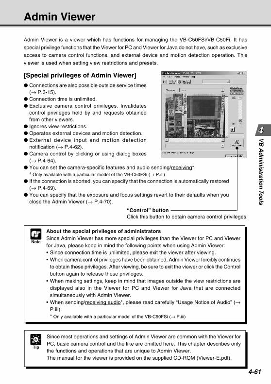
4-61
VB
Ad
min
istration
Too
lsAdmin Viewer
Admin Viewer is a viewer which has functions for managing the VB-C50FSi/VB-C50Fi. It has
special privilege functions that the Viewer for PC and Viewer for Java do not have, such as exclusive
access to camera control functions, and external device and motion detection operation. This
viewer is used when setting view restrictions and presets.
[Special privileges of Admin Viewer]
Connections are also possible outside service times(→ P.3-15).
Connection time is unlimited. Exclusive camera control privileges. Invalidates
control privileges held by and requests obtainedfrom other viewers.
Ignores view restrictions. Operates external devices and motion detection. External device input and motion detection
notification (→ P.4-62). Camera control by clicking or using dialog boxes
(→ P.4-64). You can set the camera-specific features and audio sending/receiving*.
* Only available with a particular model of the VB-C50FSi (→ P.iii)
If the connection is aborted, you can specify that the connection is automatically restored(→ P.4-69).
You can specify that the exposure and focus settings revert to their defaults when youclose the Admin Viewer (→ P.4-70).
“Control” buttonClick this button to obtain camera control privileges.
Note
About the special privileges of administratorsSince Admin Viewer has more special privileges than the Viewer for PC and Viewerfor Java, please keep in mind the following points when using Admin Viewer:• Since connection time is unlimited, please exit the viewer after viewing.• When camera control privileges have been obtained, Admin Viewer forcibly continues
to obtain these privileges. After viewing, be sure to exit the viewer or click the Controlbutton again to release these privileges.
• When making settings, keep in mind that images outside the view restrictions aredisplayed also in the Viewer for PC and Viewer for Java that are connectedsimultaneously with Admin Viewer.
• When sending/receiving audio*, please read carefully “Usage Notice of Audio” (→P.iii).* Only available with a particular model of the VB-C50FSi (→ P.iii)
Tip
Since most operations and settings of Admin Viewer are common with the Viewer forPC, basic camera control and the like are omitted here. This chapter describes onlythe functions and operations that are unique to Admin Viewer.The manual for the viewer is provided on the supplied CD-ROM (Viewer-E.pdf).
COPY

4-62
Note
If the Admin Viewer window is minimized or in full-screen mode, the notification messagefor external device input appears after the normal display is restored. Also, this messageis not displayed when the External Device Input & Motion Detect dialog box is displayed.
A message appears in the event a change occurs inthe external device input status or when motion isdetected.
Starting Up Admin Viewer
To Start Up...
1. Click the “Admin Viewer” on the VBAdmin Startup Panel or double-click the“Admin Viewer” icon on the desktop.
When the Admin Livescope window appears, click the File then the Connect. The “Cameraserver address setting” dialog box appears. Enter the following items: Host Name (The IP address set on the VB-C50FSi/VB-C50Fi, → P.3-6) User Name (root) Password (→ P.3-5)Then click the “OK” button. The video will then be displayed.
Operating External Devices and Motion Detection
Setting Notification of Changes in External Device Input and Motion
Detection StatusA message box can be displayed in the event of a change in external device input and motion
detection status.
To Make Settings...
1. Choose Setup Properties from the View menubar.
Admin Viewer
2. When the Setup properties dialog boxappears, click the “Display option” tab.
Check to be sure the “Display notification messagefor external device input and motion detection” checkbox is selected, then click “OK”.
COPY
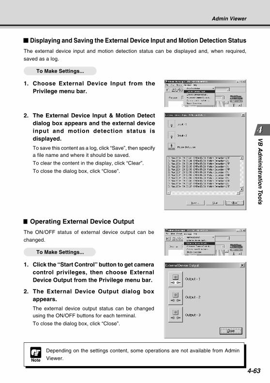
4-63
VB
Ad
min
istration
Too
ls
Displaying and Saving the External Device Input and Motion Detection Status
The external device input and motion detection status can be displayed and, when required,
saved as a log.
To Make Settings...
1. Choose External Device Input from thePrivilege menu bar.
Admin Viewer
2. The External Device Input & Motion Detectdialog box appears and the external deviceinput and motion detection status isdisplayed.
To save this content as a log, click “Save”, then specifya file name and where it should be saved.
To clear the content in the display, click “Clear”.
To close the dialog box, click “Close”.
Note
Depending on the settings content, some operations are not available from Admin
Viewer.
Operating External Device Output
The ON/OFF status of external device output can be
changed.
To Make Settings...
1. Click the “Start Control” button to get cameracontrol privileges, then choose ExternalDevice Output from the Privilege menu bar.
2. The External Device Output dialog boxappears.
The external device output status can be changedusing the ON/OFF buttons for each terminal.
To close the dialog box, click “Close”.
COPY
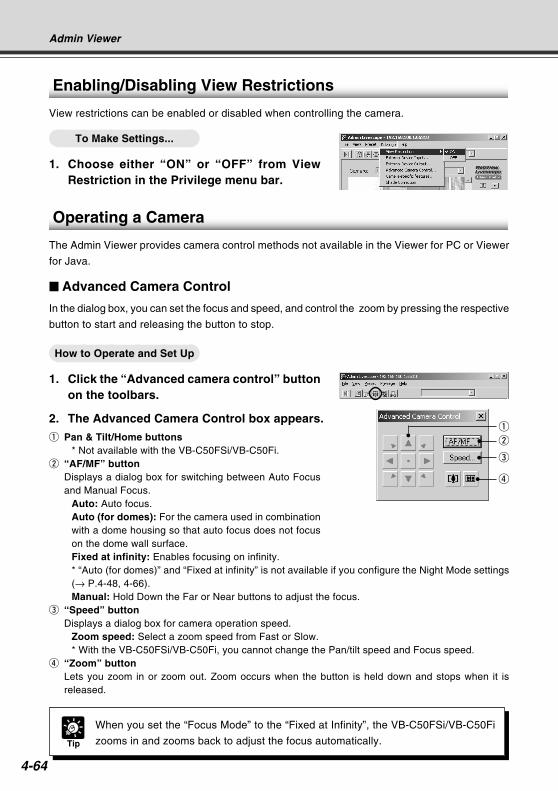
4-64
Operating a Camera
The Admin Viewer provides camera control methods not available in the Viewer for PC or Viewer
for Java.
Advanced Camera Control
In the dialog box, you can set the focus and speed, and control the zoom by pressing the respective
button to start and releasing the button to stop.
How to Operate and Set Up
1. Click the “Advanced camera control” buttonon the toolbars.
2. The Advanced Camera Control box appears.
q Pan & Tilt/Home buttons* Not available with the VB-C50FSi/VB-C50Fi.
w “AF/MF” buttonDisplays a dialog box for switching between Auto Focusand Manual Focus.
Auto: Auto focus.Auto (for domes): For the camera used in combinationwith a dome housing so that auto focus does not focuson the dome wall surface.Fixed at infinity: Enables focusing on infinity.* “Auto (for domes)” and “Fixed at infinity” is not available if you configure the Night Mode settings(→ P.4-48, 4-66).Manual: Hold Down the Far or Near buttons to adjust the focus.
e “Speed” buttonDisplays a dialog box for camera operation speed.
Zoom speed: Select a zoom speed from Fast or Slow.* With the VB-C50FSi/VB-C50Fi, you cannot change the Pan/tilt speed and Focus speed.
r “Zoom” buttonLets you zoom in or zoom out. Zoom occurs when the button is held down and stops when it isreleased.
Tip
When you set the “Focus Mode” to the “Fixed at Infinity”, the VB-C50FSi/VB-C50Fi
zooms in and zooms back to adjust the focus automatically.
Enabling/Disabling View Restrictions
View restrictions can be enabled or disabled when controlling the camera.
To Make Settings...
1. Choose either “ON” or “OFF” from ViewRestriction in the Privilege menu bar.
Admin Viewer
r
w
e
q
COPY
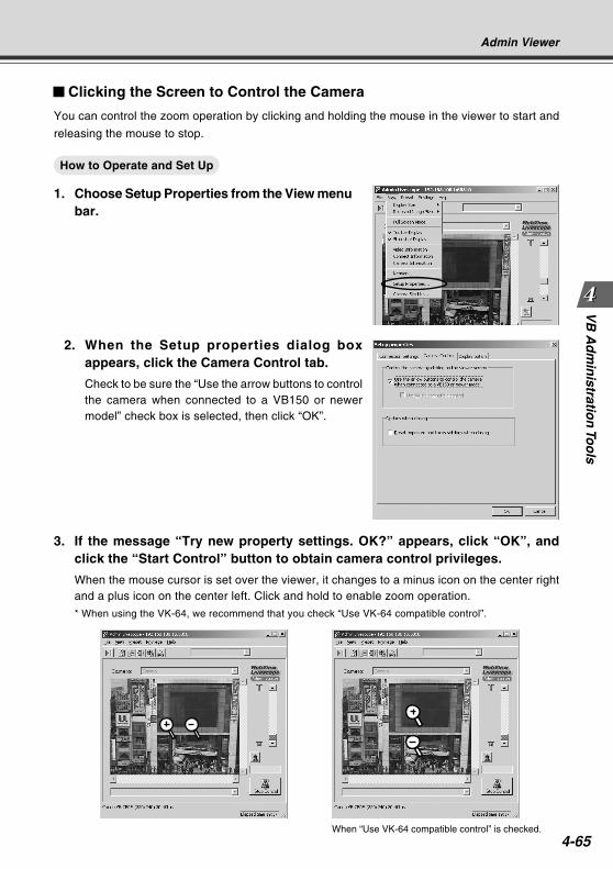
4-65
VB
Ad
min
istration
Too
ls
Clicking the Screen to Control the Camera
You can control the zoom operation by clicking and holding the mouse in the viewer to start and
releasing the mouse to stop.
How to Operate and Set Up
1. Choose Setup Properties from the View menubar.
Admin Viewer
When “Use VK-64 compatible control” is checked.
2. When the Setup properties dialog boxappears, click the Camera Control tab.
Check to be sure the “Use the arrow buttons to controlthe camera when connected to a VB150 or newermodel” check box is selected, then click “OK”.
3. If the message “Try new property settings. OK?” appears, click “OK”, andclick the “Start Control” button to obtain camera control privileges.
When the mouse cursor is set over the viewer, it changes to a minus icon on the center rightand a plus icon on the center left. Click and hold to enable zoom operation.
* When using the VK-64, we recommend that you check “Use VK-64 compatible control”.
COPY

4-66
Camera-Specific Functions
You can set up camera-specific features such as settings for exposure, digital zoom and night mode.
How to Operate and Set Up
1. Click the “Camera-specific features” buttonon the toolbar.
2. The Camera-specific features dialog boxappears.
q ExposureSelect from Auto Exposure and Manual Exposure.
w Auto ExposureThe 4 buttons to the right become active when you selectAuto Exposure. From the left the 4 buttons are NoBacklight Compensation, Low Backlight Compensation,Medium Backlight Compensation and High BacklightCompensation, and the higher the compensation, thebrighter the image becomes. Click a button to activatethe backlight compensation you need.
e “Manual Exposure”You can set Fixed Aperture, Fixed Shutter Speed and Fixed Gain.Fixed ApertureThe further to the left you move the slide bar, the more closed the aperture and the darker theimage.Conversely, the further to the right you move the slide bar, the more open the aperture and thebrighter the image.Fixed Shutter SpeedFixes shutter speed. If you specify a fast shutter speed (1/125, 1/250 etc.), the darker theimage becomes. Conversely, if you specify a slow shutter speed (1/1, 1/2 etc.) the brighter theimage becomes.Fixed GainThe further to the left you move the slide bar, the lower the gain (sensitivity for brightness) andthe darker the image. Conversely, the further to the right you move the slide bar, the higher thegain and the brighter the image.
r Digital zoomYou can enlarge the image using the digital zoom. When you use zoom, other images sent tothe Viewer are enlarged also.* Digital zoom is not available if you configure the “Manual Exposure” or Night Mode.* When using the digital zoom, the video quality is deteriorated as it zooms in closer.
t “Night vision”Set up night mode with Night Vision.Night ModeCheck to cancel the Infrared Cut Filter, enabling you to see infrared images. In such case, theimages are in black and white.* “Auto (for domes)” and “Fixed at infinity” (→ P.4-64) is not available if you configure the Night Mode
settings.
Admin Viewer
qw
e
r
t
COPY
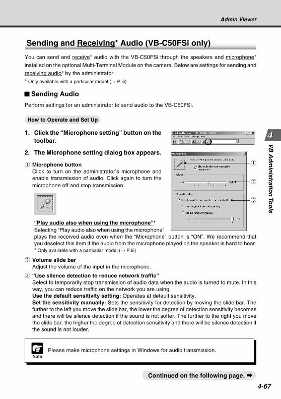
4-67
VB
Ad
min
istration
Too
ls
Sending and Receiving* Audio (VB-C50FSi only)
You can send and receive* audio with the VB-C50FSi through the speakers and microphone*
installed on the optional Multi-Terminal Module on the camera. Below are settings for sending and
receiving audio* by the administrator.
* Only available with a particular model (→ P.iii)
Sending Audio
Perform settings for an administrator to send audio to the VB-C50FSi.
How to Operate and Set Up
1. Click the “Microphone setting” button on thetoolbar.
2. The Microphone setting dialog box appears.
q Microphone buttonClick to turn on the administrator’s microphone andenable transmission of audio. Click again to turn themicrophone off and stop transmission.
“Play audio also when using the microphone”*Selecting “Play audio also when using the microphone”plays the received audio even when the “Microphone” button is “ON”. We recommend thatyou deselect this item if the audio from the microphone played on the speaker is hard to hear.* Only available with a particular model (→ P.iii)
w Volume slide barAdjust the volume of the input in the microphone.
e “Use silence detection to reduce network traffic”Select to temporarily stop transmission of audio data when the audio is turned to mute. In thisway, you can reduce traffic on the network you are using.Use the default sensitivity setting: Operates at default sensitivity.Set the sensitivity manually: Sets the sensitivity for detection by moving the slide bar. Thefurther to the left you move the slide bar, the lower the degree of detection sensitivity becomesand there will be silence detection if the sound is not softer. The further to the right you movethe slide bar, the higher the degree of detection sensitivity and there will be silence detection ifthe sound is not louder.
q
w
e
NotePlease make microphone settings in Windows for audio transmission.
Continued on the following page. a
Admin Viewer
COPY
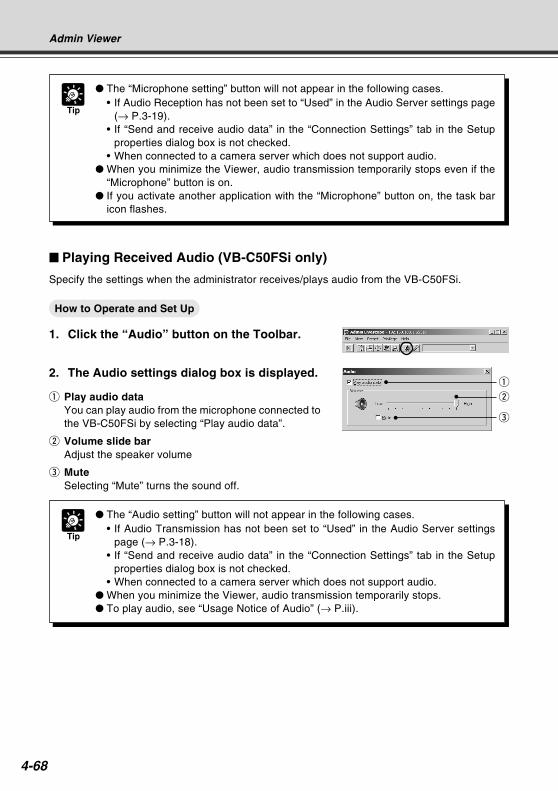
4-68
Tip
The “Microphone setting” button will not appear in the following cases.• If Audio Reception has not been set to “Used” in the Audio Server settings page
(→ P.3-19).• If “Send and receive audio data” in the “Connection Settings” tab in the Setup
properties dialog box is not checked.• When connected to a camera server which does not support audio.
When you minimize the Viewer, audio transmission temporarily stops even if the“Microphone” button is on.
If you activate another application with the “Microphone” button on, the task baricon flashes.
Playing Received Audio (VB-C50FSi only)
Specify the settings when the administrator receives/plays audio from the VB-C50FSi.
How to Operate and Set Up
1. Click the “Audio” button on the Toolbar.
2. The Audio settings dialog box is displayed.
q Play audio dataYou can play audio from the microphone connected tothe VB-C50FSi by selecting “Play audio data”.
w Volume slide barAdjust the speaker volume
e MuteSelecting “Mute” turns the sound off.
Tip
The “Audio setting” button will not appear in the following cases.• If Audio Transmission has not been set to “Used” in the Audio Server settings
page (→ P.3-18).• If “Send and receive audio data” in the “Connection Settings” tab in the Setup
properties dialog box is not checked.• When connected to a camera server which does not support audio.
When you minimize the Viewer, audio transmission temporarily stops. To play audio, see “Usage Notice of Audio” (→ P.iii).
w
q
e
Admin Viewer
COPY
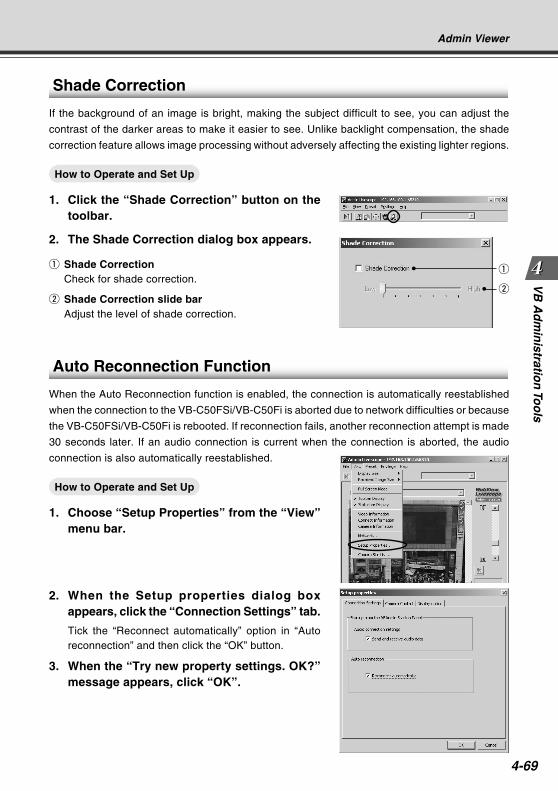
4-69
VB
Ad
min
istration
Too
ls
Shade Correction
If the background of an image is bright, making the subject difficult to see, you can adjust the
contrast of the darker areas to make it easier to see. Unlike backlight compensation, the shade
correction feature allows image processing without adversely affecting the existing lighter regions.
How to Operate and Set Up
1. Click the “Shade Correction” button on thetoolbar.
2. The Shade Correction dialog box appears.
q Shade CorrectionCheck for shade correction.
w Shade Correction slide barAdjust the level of shade correction.
q
w
Admin Viewer
Auto Reconnection Function
When the Auto Reconnection function is enabled, the connection is automatically reestablished
when the connection to the VB-C50FSi/VB-C50Fi is aborted due to network difficulties or because
the VB-C50FSi/VB-C50Fi is rebooted. If reconnection fails, another reconnection attempt is made
30 seconds later. If an audio connection is current when the connection is aborted, the audio
connection is also automatically reestablished.
How to Operate and Set Up
1. Choose “Setup Properties” from the “View”menu bar.
2. When the Setup properties dialog boxappears, click the “Connection Settings” tab.
Tick the “Reconnect automatically” option in “Autoreconnection” and then click the “OK” button.
3. When the “Try new property settings. OK?”message appears, click “OK”.
COPY
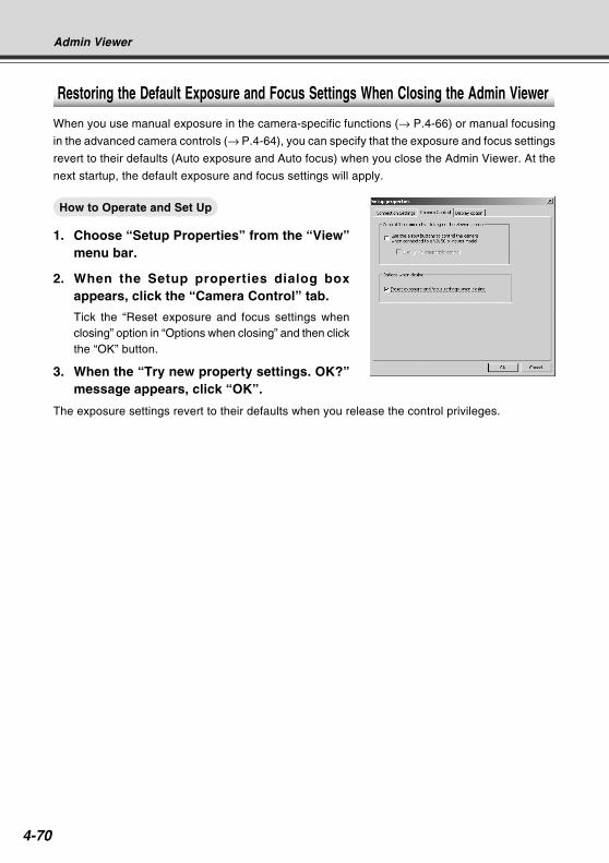
4-70
Admin Viewer
Restoring the Default Exposure and Focus Settings When Closing the Admin Viewer
When you use manual exposure in the camera-specific functions (→ P.4-66) or manual focusing
in the advanced camera controls (→ P.4-64), you can specify that the exposure and focus settings
revert to their defaults (Auto exposure and Auto focus) when you close the Admin Viewer. At the
next startup, the default exposure and focus settings will apply.
How to Operate and Set Up
1. Choose “Setup Properties” from the “View”menu bar.
2. When the Setup properties dialog boxappears, click the “Camera Control” tab.
Tick the “Reset exposure and focus settings whenclosing” option in “Options when closing” and then clickthe “OK” button.
3. When the “Try new property settings. OK?”message appears, click “OK”.
The exposure settings revert to their defaults when you release the control privileges.
COPY
Creating Web Pages forVideo Distribution
This chapter describes how to use the VB-C50FSi/VB-C50Fi
to webcast information.
Picture data can be distributed in various ways, including
displaying video or still pictures and displaying multiple
images on a Web page.
Chapter
COPY
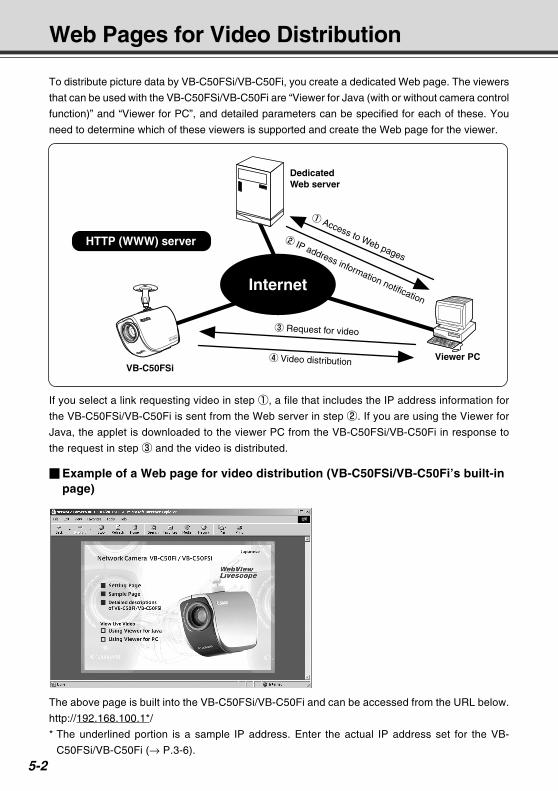
5-2
Web Pages for Video Distribution
If you select a link requesting video in step 1, a file that includes the IP address information for
the VB-C50FSi/VB-C50Fi is sent from the Web server in step 2. If you are using the Viewer for
Java, the applet is downloaded to the viewer PC from the VB-C50FSi/VB-C50Fi in response to
the request in step 3 and the video is distributed.
To distribute picture data by VB-C50FSi/VB-C50Fi, you create a dedicated Web page. The viewers
that can be used with the VB-C50FSi/VB-C50Fi are “Viewer for Java (with or without camera control
function)” and “Viewer for PC”, and detailed parameters can be specified for each of these. You
need to determine which of these viewers is supported and create the Web page for the viewer.
The above page is built into the VB-C50FSi/VB-C50Fi and can be accessed from the URL below.
http://192.168.100.1*/
* The underlined portion is a sample IP address. Enter the actual IP address set for the VB-
C50FSi/VB-C50Fi (→ P.3-6).
Example of a Web page for video distribution (VB-C50FSi/VB-C50Fi’s built-inpage)
HTTP (WWW) server
DedicatedWeb server
Viewer PC
1 Access to Web pages
3 Request for video
4 Video distribution
2 IP address information notificationInternet
VB-C50FSi
COPY
Creatin
g W
eb P
ages
5-3
Web Pages for Video Distribution
Tip
You can use the Language setting function for the Browser to create a multi-lingual
Web site. For example, if you set the French-language top page as index-fr.html and
the English-language top page as index.html and supply users with a URL address
terminates in slash, such as http://192.168.100.1/sample/, the server will transmit a
file that corresponds with the language setting for the Browser. For further information
on the Language setting function for the Browser, refer to the Browser Help.
* The underlined portion is a sample IP address. Enter the actual IP address set for
the VB-C50FSi/VB-C50Fi (→ P.3-6).
Note
The VB-C50FSi/VB-C50Fi includes a built-in Web server. If the content of the Web
pages used for distributing videos is stored onto the flash memory in the VB-C50FSi/
VB-C50Fi, the VB-C50FSi/VB-C50Fi can be used by itself for distributing Web pages
and videos over the Web. Please refer to page 5-8 for procedures on how to save
Web page data.
COPY
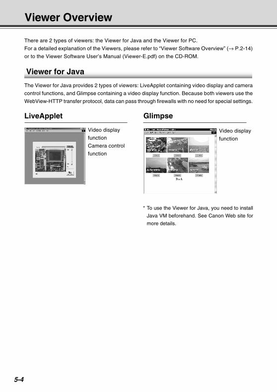
5-4
There are 2 types of viewers: the Viewer for Java and the Viewer for PC.
For a detailed explanation of the Viewers, please refer to “Viewer Software Overview” (→ P.2-14)
or to the Viewer Software User’s Manual (Viewer-E.pdf) on the CD-ROM.
Viewer for Java
The Viewer for Java provides 2 types of viewers: LiveApplet containing video display and camera
control functions, and Glimpse containing a video display function. Because both viewers use the
WebView-HTTP transfer protocol, data can pass through firewalls with no need for special settings.
Viewer Overview
Video display
function
Camera control
function
LiveApplet Glimpse
Video display
function
* To use the Viewer for Java, you need to install
Java VM beforehand. See Canon Web site for
more details.
COPY

Creatin
g W
eb P
ages
5-5
Viewer Overview
Note
Viewer Software User’s Manual is provided on the CD-ROM supplied with the
VB-C50FSi/VB-C50Fi (Viewer-E.pdf).
Viewer for PC
The Viewer for PC provides video display and camera control functions. In addition to WebView-
HTTP, the VB-C50FSi/VB-C50Fi also supports Canon’s WebView-TCP transfer protocol.
Video display
function
Camera control
function
* You need to install the Viewer for PC from the
“VBToolsInstall.exe” file on the supplied CD-ROM (→ P.2-13).
COPY
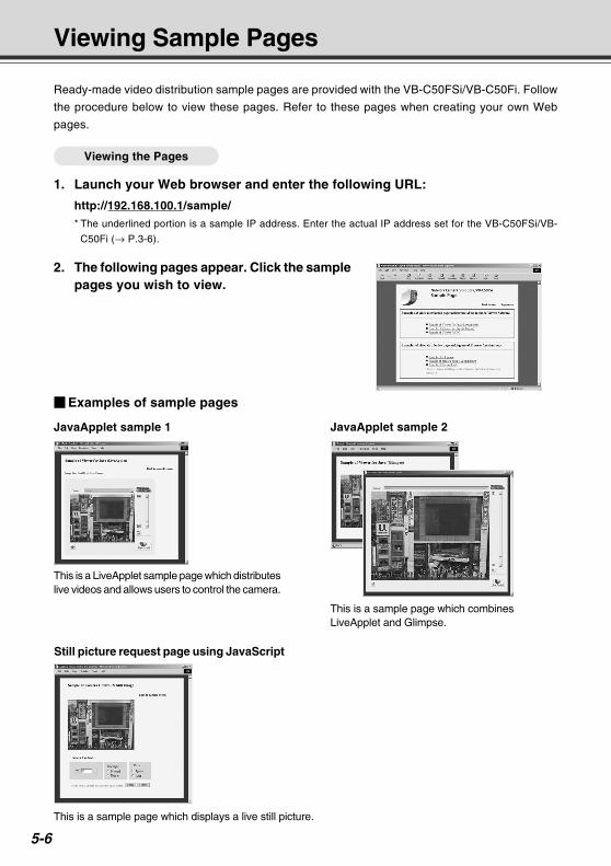
5-6
This is a LiveApplet sample page which distributeslive videos and allows users to control the camera.
This is a sample page which combinesLiveApplet and Glimpse.
Examples of sample pages
JavaApplet sample 1 JavaApplet sample 2
Still picture request page using JavaScript
Ready-made video distribution sample pages are provided with the VB-C50FSi/VB-C50Fi. Follow
the procedure below to view these pages. Refer to these pages when creating your own Web
pages.
Viewing the Pages
1. Launch your Web browser and enter the following URL:
http://192.168.100.1/sample/
* The underlined portion is a sample IP address. Enter the actual IP address set for the VB-C50FSi/VB-
C50Fi (→ P.3-6).
Viewing Sample Pages
This is a sample page which displays a live still picture.
2. The following pages appear. Click the samplepages you wish to view.
COPY
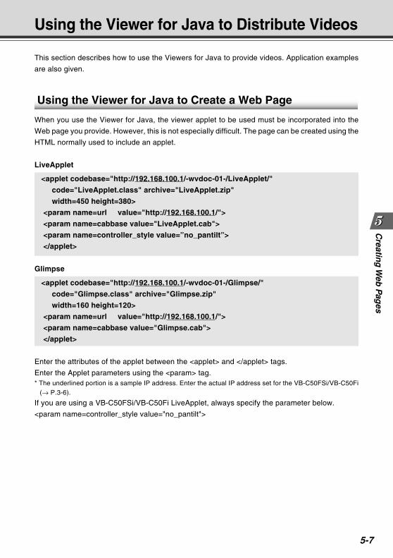
Creatin
g W
eb P
ages
5-7
This section describes how to use the Viewers for Java to provide videos. Application examples
are also given.
Using the Viewer for Java to Distribute Videos
Using the Viewer for Java to Create a Web Page
When you use the Viewer for Java, the viewer applet to be used must be incorporated into the
Web page you provide. However, this is not especially difficult. The page can be created using the
HTML normally used to include an applet.
LiveApplet
<applet codebase="http://192.168.100.1/-wvdoc-01-/LiveApplet/"
code="LiveApplet.class" archive="LiveApplet.zip"
width=450 height=380>
<param name=url value="http://192.168.100.1/">
<param name=cabbase value="LiveApplet.cab">
<param name=controller_style value=”no_pantilt”>
</applet>
Glimpse
<applet codebase="http://192.168.100.1/-wvdoc-01-/Glimpse/"
code="Glimpse.class" archive="Glimpse.zip"
width=160 height=120>
<param name=url value="http://192.168.100.1/">
<param name=cabbase value="Glimpse.cab">
</applet>
Enter the attributes of the applet between the <applet> and </applet> tags.
Enter the Applet parameters using the <param> tag.* The underlined portion is a sample IP address. Enter the actual IP address set for the VB-C50FSi/VB-C50Fi
(→ P.3-6).
If you are using a VB-C50FSi/VB-C50Fi LiveApplet, always specify the parameter below.
<param name=controller_style value="no_pantilt">
COPY
5-8
Using the Viewer for Java to Distribute Videos
Saving Web Page Data
The VB-C50FSi/VB-C50Fi is equipped with a Flash memory where Web page data can be saved.
Data is saved by transferring the data files using FTP. The data is placed as a file under /usr/html/
local.
Device File system URL(accessed by an ftp client) (accessed from a Web browser)
On-board flash ftp://IP address/usr/html/local http://IP address/local/memory
Note
Output performance may suffer if there is insufficient free space in the on-board
file system. Ensure that only the minimum amount of data required is stored in the
on-board file system (→ P.3-28).
Using “Restore Settings” (→ P.3-29, 7-21) deletes all saved data. Back up your
data before using this function.
COPY
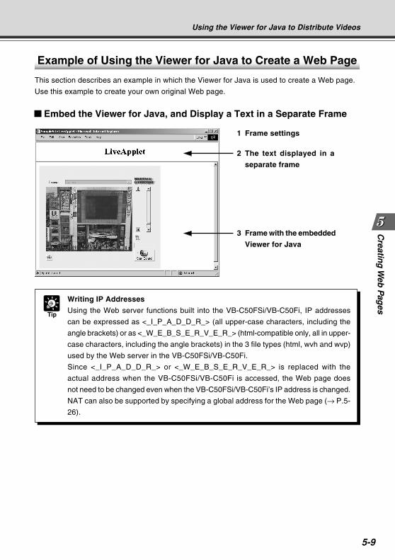
Creatin
g W
eb P
ages
5-9
Using the Viewer for Java to Distribute Videos
Example of Using the Viewer for Java to Create a Web Page
This section describes an example in which the Viewer for Java is used to create a Web page.
Use this example to create your own original Web page.
Tip
Writing IP Addresses
Using the Web server functions built into the VB-C50FSi/VB-C50Fi, IP addresses
can be expressed as <_I_P_A_D_D_R_> (all upper-case characters, including the
angle brackets) or as <_W_E_B_S_E_R_V_E_R_> (html-compatible only, all in upper-
case characters, including the angle brackets) in the 3 file types (html, wvh and wvp)
used by the Web server in the VB-C50FSi/VB-C50Fi.
Since <_I_P_A_D_D_R_> or <_W_E_B_S_E_R_V_E_R_> is replaced with the
actual address when the VB-C50FSi/VB-C50Fi is accessed, the Web page does
not need to be changed even when the VB-C50FSi/VB-C50Fi’s IP address is changed.
NAT can also be supported by specifying a global address for the Web page (→ P.5-
26).
Embed the Viewer for Java, and Display a Text in a Separate Frame
2 The text displayed in a
separate frame
3 Frame with the embedded
Viewer for Java
1 Frame settings
COPY
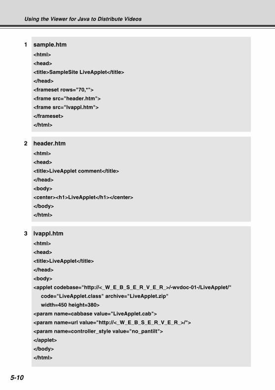
5-10
1 sample.htm
<html>
<head>
<title>SampleSite LiveApplet</title>
</head>
<frameset rows="70,*">
<frame src="header.htm">
<frame src="lvappl.htm">
</frameset>
</html>
2 header.htm
<html>
<head>
<title>LiveApplet comment</title>
</head>
<body>
<center><h1>LiveApplet</h1></center>
</body>
</html>
3 lvappl.htm
<html>
<head>
<title>LiveApplet</title>
</head>
<body>
<applet codebase="http://<_W_E_B_S_E_R_V_E_R_>/-wvdoc-01-/LiveApplet/"
code="LiveApplet.class" archive="LiveApplet.zip"
width=450 height=380>
<param name=cabbase value="LiveApplet.cab">
<param name=url value="http://<_W_E_B_S_E_R_V_E_R_>/">
<param name=controller_style value="no_pantilt">
</applet>
</body>
</html>
Using the Viewer for Java to Distribute Videos
COPY
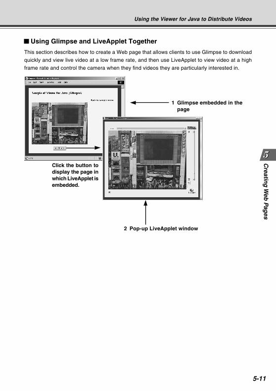
Creatin
g W
eb P
ages
5-11
Click the button todisplay the page inwhich LiveApplet isembedded.
Using Glimpse and LiveApplet Together
This section describes how to create a Web page that allows clients to use Glimpse to download
quickly and view live video at a low frame rate, and then use LiveApplet to view video at a high
frame rate and control the camera when they find videos they are particularly interested in.
1 Glimpse embedded in thepage
2 Pop-up LiveApplet window
Using the Viewer for Java to Distribute Videos
COPY
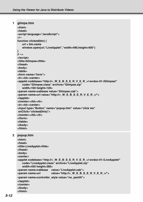
5-12
1 glimps.htm<html><head><script language="JavaScript"><!--function clicked(btn)
url = btn.namewindow.open(url,"LiveApplet","width=490,height=400")
// --></script><title>Glimpse</title></head><body><table><form name="form"><tr><td><center><applet codebase="http://<_W_E_B_S_E_R_V_E_R_>/-wvdoc-01-/Glimpse/"
code="Glimpse.class" archive="Glimpse.zip"width=160 height=120>
<param name=cabbase value="Glimpse.cab"><param name=url value="http://<_W_E_B_S_E_R_V_E_R_>/"></applet></center></td></tr><tr><td><center><input type="Button" name="popup.htm" value="click me" onClick="clicked(this)"></center></td></tr></form></table></body></html>
2 popup.htm<html><head><title>LiveApplet</title></head><body><center><applet codebase="http://<_W_E_B_S_E_R_V_E_R_>/-wvdoc-01-/LiveApplet/"
code="LiveApplet.class" archive="LiveApplet.zip"width=450 height=380>
<param name=cabbase value="LiveApplet.cab"><param name=url value="http://<_W_E_B_S_E_R_V_E_R_>/">
<param name=controller_style value="no_pantilt"></applet></center></body></html>
Using the Viewer for Java to Distribute Videos
COPY
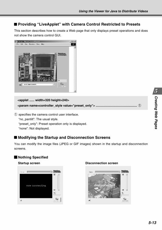
Creatin
g W
eb P
ages
5-13
Providing “LiveApplet” with Camera Control Restricted to Presets
This section describes how to create a Web page that only displays preset operations and does
not show the camera control GUI.
Modifying the Startup and Disconnection Screens
You can modify the image files (JPEG or GIF images) shown in the startup and disconnection
screens.
Nothing Specified
Startup screen Disconnection screen
<applet ...... width=320 height=240>
<param name=controller_style value="preset_only"> ................................................ 1
1 specifies the camera control user interface.
“no_pantilt”: The usual style.
“preset_only”: Preset operation only is displayed.
“none”: Not displayed.
Using the Viewer for Java to Distribute Videos
COPY
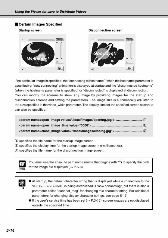
5-14
Certain Images Specified
Startup screen Disconnection screen
If no particular image is specified, the “connecting to hostname” (when the hostname parameter is
specified) or “now connecting” animation is displayed at startup and the “disconnected hostname”
(when the hostname parameter is specified) or “disconnected” is displayed at disconnection.
You can modify the screens to show any image by providing images for the startup and
disconnection screens and setting the parameters. The image size is automatically adjusted to
the size specified in the video_width parameter. The display time for the specified screen at startup
can also be specified.
<param name=open_image value="/local/images/opening.jpg"> ............................. 1
<param name=open_image_time value="3000"> ........................................................ 2
<param name=close_image value="/local/images/closing.jpg"> .............................. 3
1 specifies the file name for the startup image screen.
2 specifies the display time for the startup image screen (in milliseconds).
3 specifies the file name for the disconnection image screen.
Note
You must use the absolute path name (name that begins with “/”) to specify the path
for the image file displayed (→ P.5-8).
Tip
At startup, the default character string that is displayed while a connection to the
VB-C50FSi/VB-C50Fi is being established is “now connecting”, but there is also a
parameter called “connect_msg” for changing this character string. For additional
parameters for changing display character strings, see page 5-17.
If the user’s service time has been set (→ P.3-15), screen images are not displayed
outside the specified time.
Using the Viewer for Java to Distribute Videos
COPY
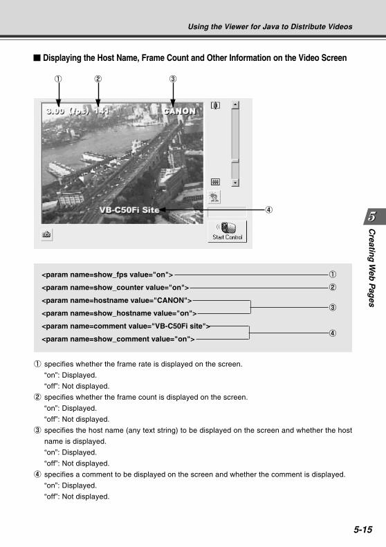
Creatin
g W
eb P
ages
5-15
Displaying the Host Name, Frame Count and Other Information on the Video Screen
<param name=show_fps value="on"> 1
<param name=show_counter value="on"> 2
<param name=hostname value="CANON">
<param name=show_hostname value="on">3
<param name=comment value="VB-C50Fi site">
<param name=show_comment value="on">4
1 specifies whether the frame rate is displayed on the screen.
“on”: Displayed.
“off”: Not displayed.
2 specifies whether the frame count is displayed on the screen.
“on”: Displayed.
“off”: Not displayed.
3 specifies the host name (any text string) to be displayed on the screen and whether the host
name is displayed.
“on”: Displayed.
“off”: Not displayed.
4 specifies a comment to be displayed on the screen and whether the comment is displayed.
“on”: Displayed.
“off”: Not displayed.
1 2 3
4
Using the Viewer for Java to Distribute Videos
COPY
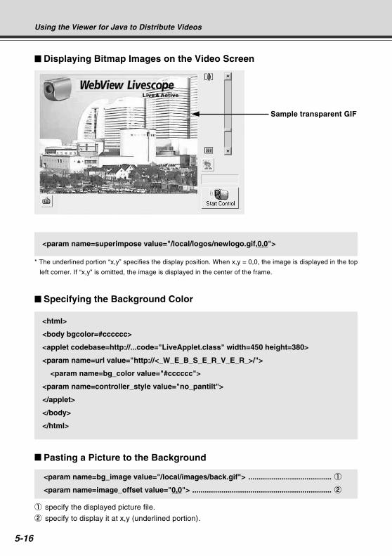
5-16
Displaying Bitmap Images on the Video Screen
<param name=superimpose value="/local/logos/newlogo.gif,0,0">
* The underlined portion “x,y” specifies the display position. When x,y = 0,0, the image is displayed in the top
left corner. If “x,y” is omitted, the image is displayed in the center of the frame.
Sample transparent GIF
Specifying the Background Color
<html>
<body bgcolor=#cccccc>
<applet codebase=http://...code="LiveApplet.class" width=450 height=380>
<param name=url value="http://<_W_E_B_S_E_R_V_E_R_>/">
<param name=bg_color value="#cccccc">
<param name=controller_style value="no_pantilt">
</applet>
</body>
</html>
Pasting a Picture to the Background
<param name=bg_image value="/local/images/back.gif"> ........................................ 1
<param name=image_offset value="0,0"> ................................................................... 2
1 specify the displayed picture file.
2 specify to display it at x,y (underlined portion).
Using the Viewer for Java to Distribute Videos
COPY
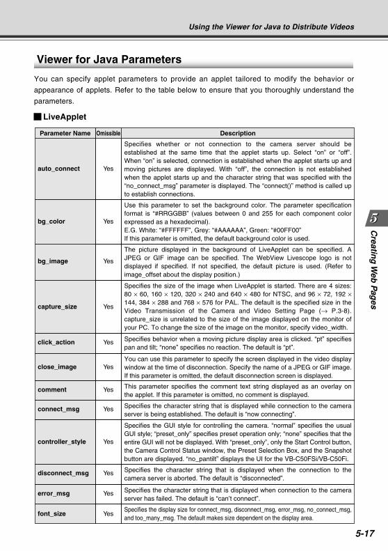
Creatin
g W
eb P
ages
5-17
Viewer for Java Parameters
You can specify applet parameters to provide an applet tailored to modify the behavior or
appearance of applets. Refer to the table below to ensure that you thoroughly understand the
parameters.
LiveApplet
Using the Viewer for Java to Distribute Videos
Specifies whether or not connection to the camera server should be established at the same time that the applet starts up. Select “on” or “off”. When “on” is selected, connection is established when the applet starts up and moving pictures are displayed. With “off”, the connection is not established when the applet starts up and the character string that was specified with the “no_connect_msg” parameter is displayed. The “connect()” method is called up to establish connections.
Yesauto_connect
Use this parameter to set the background color. The parameter specification format is “#RRGGBB” (values between 0 and 255 for each component color expressed as a hexadecimal).E.G. White: “#FFFFFF”, Grey: “#AAAAAA”, Green: “#00FF00”If this parameter is omitted, the default background color is used.
Yesbg_color
The picture displayed in the background of LiveApplet can be specified. A JPEG or GIF image can be specified. The WebView Livescope logo is not displayed if specified. If not specified, the default picture is used. (Refer to image_offset about the display position.)
Yesbg_image
Specifies the size of the image when LiveApplet is started. There are 4 sizes: 80 × 60, 160 × 120, 320 × 240 and 640 × 480 for NTSC, and 96 × 72, 192 × 144, 384 × 288 and 768 × 576 for PAL. The default is the specified size in the Video Transmission of the Camera and Video Setting Page (→ P.3-8). capture_size is unrelated to the size of the image displayed on the monitor of your PC. To change the size of the image on the monitor, specify video_width.
Yescapture_size
Specifies behavior when a moving picture display area is clicked. “pt” specifies pan and tilt; “none” specifies no reaction. The default is “pt”.
Yesclick_action
You can use this parameter to specify the screen displayed in the video display window at the time of disconnection. Specify the name of a JPEG or GIF image. If this parameter is omitted, the default disconnection screen is displayed.
Yesclose_image
This parameter specifies the comment text string displayed as an overlay on the applet. If this parameter is omitted, no comment is displayed.
Yescomment
Specifies the character string that is displayed while connection to the camera server is being established. The default is “now connecting”.
Yesconnect_msg
Specifies the GUI style for controlling the camera. “normal” specifies the usual GUI style; “preset_only” specifies preset operation only; “none” specifies that the entire GUI will not be displayed. With “preset_only”, only the Start Control button, the Camera Control Status window, the Preset Selection Box, and the Snapshot button are displayed. “no_pantilt” displays the UI for the VB-C50FSi/VB-C50Fi.
Yescontroller_style
Specifies the character string that is displayed when the connection to the camera server is aborted. The default is “disconnected”.
Yesdisconnect_msg
Specifies the character string that is displayed when connection to the camera server has failed. The default is “can’t connect”.
Yeserror_msg
Specifies the display size for connect_msg, disconnect_msg, error_msg, no_connect_msg, and too_many_msg. The default makes size dependent on the display area.
Yesfont_size
DescriptionOmissibleParameter Name
COPY
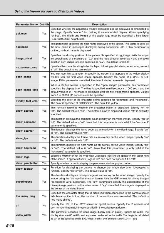
5-18
Using the Viewer for Java to Distribute Videos
When a startup screen is specified in the “open_image” parameter, this parameter specifies the display time. The time is specified in milliseconds (1/1000 sec.), and the default value is 0. The image is displayed until the first video frame appears. Values from 0 to 30000 (30 seconds) can be specified.
Yesopen_image_time
Specifies the color of the character string specified for “comment” and “hostname”. The color is specified at “#RRGGBB”. The default is yellow.
Yesoverlay_font_color
This function specifies whether the Snapshot button is displayed. Specify “on” or “off”. The default value is “on”. The button is always displayed unless “off” is explicitly specified.
Yesshow_capture
This function displays the comment as an overlay on the video image. Specify “on” or “off”. The default value is “off”. Note that this parameter is only valid if the “comment” parameter is specified.
Yesshow_comment
This function displays the frame count as an overlay on the video image. Specify “on” or “off”. The default value is “off”.
Yesshow_counter
This function displays the frame rate as an overlay on the video image. Specify “on” or “off”. The default value is “off”.
Yesshow_fps
This function displays the host name as an overlay on the video image. Specify “on” or “off”. The default value is “off”. Note that this parameter is only valid if the “hostname” parameter is specified.
Yesshow_hostname
Specifies whether or not the WebView Livescope logo should appear in the upper right of the screen. It appears if show_logo is “on” and does not appear if it is “off”.
Yesshow_logo
Function for displaying the buttons to change the image size when LiveApplet is running. Specify “on” or “off”. The default value is “off”.
Yesshow_toolbar
Specify whether or not to display the panorama window pop-up button.Yesshow_panobutton
This function displays a bitmap image as an overlay on the video image. Specify the image using the “bitmap-filename,x,y” format. Use the GIF format for bitmap images (transparent GIFs supported). The “x,y” parameters specify the coordinates of the bitmap image position on the video frame. If “x,y” is omitted, the image is displayed in the center of the video frame.
Yessuperimpose
Specifies the character string that is displayed when connection to the camera server fails because the limit on the number of connections was exceeded. The default is “too many clients”.
Yestoo_many_msg
Specify the URL of the HTTP server for applet access. Specify the IP address and port number that match those specified in the codebase attribute.
Nourl
This parameter specifies the video image display size (in pixels). Specify the width. The display sizes are 80 to 640, and any value can be set as the width. The height is calculated as 3/4 of the specified width. E.G. video_width=“240” (height = 240 × 3/4 = 180.)
Yesvideo_width
Specifies the display position of the picture file specified at bg_image. With the upper left coordinates of the picture at “0,0” and the right direction given as x and the down direction as y, image_offset is specified as “x,y”. The default is “335,0”.
Yesimage_offset
Specifies the character string to be displayed following applet startup when auto_connect is “off”. The default is “no connection”.
Yesno_connect_msg
You can use this parameter to specify the screen that appears in the video display window until the first video image appears. Specify the name of a JPEG or GIF image. If this parameter is omitted, the default startup screen is displayed.
Yesopen_image
Specifies whether the panorama window should be pop-up displayed or embedded in the page. Specify “embed” for making it an embedded display. When specifying “embed”, the Width and Height of the applet tags must be specified a little larger (E.G. width=500; height=660).
Yesgui_type
This parameter specifies the host name displayed in the applet. This value is used as the host name in messages displayed during connection, etc. If this parameter is omitted, no host name is displayed.
Yeshostname
DescriptionOmissibleParameter Name
COPY
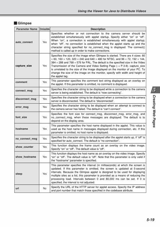
Creatin
g W
eb P
ages
5-19
Using the Viewer for Java to Distribute Videos
Specifies whether or not connection to the camera server should be established simultaneously with applet startup. Specify either “on” or “off”. When “on”, a connection is established simultaneously with applet startup; when “off”, no connection is established when the applet starts up and the character string specified for no_connect_msg is displayed. The connect() method is called up in order to make connections.
Yesauto_connect
Specifies the size of the image when Glimpse is started. There are 4 sizes: 80 × 60, 160 × 120, 320 × 240 and 640 × 480 for NTSC, and 96 × 72, 192 × 144, 384 × 288 and 768 × 576 for PAL. The default is the specified size in the Video Transmission of the Camera and Video Setting Page (→ P.3-8). capture_size is unrelated to the size of the image displayed on the monitor of your PC. To change the size of the image on the monitor, specify with width and height of the applet tag.
Yescapture_size
This parameter specifies the comment text string displayed as an overlay on the applet. If this parameter is omitted, no comment is displayed.
Yescomment
Specifies the character string to be displayed while a connection to the camera server is being established. The default is “now connecting”.
Yesconnect_msg
Specifies the character string to be displayed when a connection to the camera server is disconnected. The default is “disconnected”.
Yesdisconnect_msg
Specifies the character string to be displayed when an attempt to connect to the camera server has failed. The default is “can’t connect”.
Yeserror_msg
Specifies the font size for connect_msg, disconnect_msg, error_msg, and no_connect_msg, when these messages are displayed. The default is to depend on the display area.
Yesfont_size
This parameter specifies the host name displayed in the applet. This value is used as the host name in messages displayed during connection, etc. If this parameter is omitted, no host name is displayed.
Yeshostname
Specifies the character string to be displayed after the applet starts up, if “off” is specified for auto_connect. The default is “no connection”.
Yesno_connect_msg
This function displays the frame count as an overlay on the video image. Specify “on” or “off”. The default value is “off”.
Yesshow_counter
This function displays the host name as an overlay on the video image. Specify “on” or “off”. The default value is “off”. Note that this parameter is only valid if the “hostname” parameter is specified.
Yesshow_hostname
This parameter specifies the interval (in milliseconds) at which the screen is updated. If this parameter is omitted, the screen is updated at 5-second intervals. Because the Glimpse applet is designed to be used for displaying multiple sites as a list, this parameter is provided as a means of reducing the processing load. Intervals between 0 and 80,000 ms can be set. If 0 is specified, the interval is not adjusted.
Yessleep
Specify the URL of the HTTP server for applet access. Specify the IP address and port number that match those specified in the codebase attribute.
Nourl
DescriptionOmissibleParameter Name
Glimpse
COPY
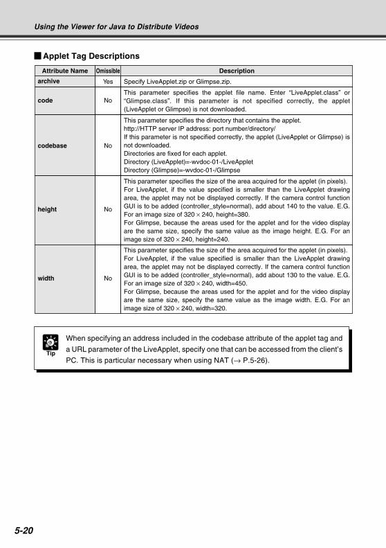
5-20
Using the Viewer for Java to Distribute Videos
Tip
When specifying an address included in the codebase attribute of the applet tag and
a URL parameter of the LiveApplet, specify one that can be accessed from the client’s
PC. This is particular necessary when using NAT (→ P.5-26).
Specify LiveApplet.zip or Glimpse.zip.Yesarchive
This parameter specifies the applet file name. Enter “LiveApplet.class” or “Glimpse.class”. If this parameter is not specified correctly, the applet (LiveApplet or Glimpse) is not downloaded.
Nocode
This parameter specifies the directory that contains the applet. http://HTTP server IP address: port number/directory/If this parameter is not specified correctly, the applet (LiveApplet or Glimpse) is not downloaded. Directories are fixed for each applet.Directory (LiveApplet)=-wvdoc-01-/LiveAppletDirectory (Glimpse)=-wvdoc-01-/Glimpse
Nocodebase
This parameter specifies the size of the area acquired for the applet (in pixels).For LiveApplet, if the value specified is smaller than the LiveApplet drawing area, the applet may not be displayed correctly. If the camera control function GUI is to be added (controller_style=normal), add about 140 to the value. E.G. For an image size of 320 × 240, height=380.For Glimpse, because the areas used for the applet and for the video display are the same size, specify the same value as the image height. E.G. For an image size of 320 × 240, height=240.
Noheight
This parameter specifies the size of the area acquired for the applet (in pixels).For LiveApplet, if the value specified is smaller than the LiveApplet drawing area, the applet may not be displayed correctly. If the camera control function GUI is to be added (controller_style=normal), add about 130 to the value. E.G. For an image size of 320 × 240, width=450.For Glimpse, because the areas used for the applet and for the video display are the same size, specify the same value as the image width. E.G. For an image size of 320 × 240, width=320.
Nowidth
DescriptionOmissibleAttribute Name
Applet Tag Descriptions
COPY
Creatin
g W
eb P
ages
5-21
This section describes how to use the Viewer for PC to provide videos. Application examples are
also given.
If a client is using the Viewer for PC to receive videos, the video sender must set up the Web
server and create the necessary wvh files.
MIME type video/x-webview-h
Extension wvh
For Apache
In the settings for added the MIME type in Apache, edit the “mime.types” file in the “conf”
directory.
Use the following syntax to add the required MIME type to the PC:
type/subtype extension
The settings for Viewer are as follows:
video/x-webview-h wvh
Using the Viewer for PC to Distribute Videos
Note
If the MIME setting is not specified correctly for the Web server, you may not be able
to launch the Viewer for PC. Be sure to specify the setting correctly.
Tip
The settings below are not required if the VB-C50FSi/VB-C50Fi’s built-in Web server
is used.
See page 5-8 for saving Web page data.
Setting Up the Web Server
Set up the Web server to be used for providing Web pages. Add the MIME type to the Web server
software and specify the extension. Refer to the manual for your Web server software for details.
COPY
5-22
Tip
Instead of an IP address, you can also type in <_I_P_A_D_D_R_> (→ P.5-9).
Example: <_I_P_A_D_D_R_> 65310
<_I_P_A_D_D_R_> 65311
wvhttp:<_I_P_A_D_D_R_> 80
wvaudio: <_I_P_A_D_D_R_> 80 (Only available with a particular model
of the VB-C50FSi)
Using the Viewer for PC to Distribute Videos
1. Use a text editor or similar program to create a new text file and type thefollowing type of code in the file:
(Example) 192.168.100.1 65310
192.168.100.1 65311
wvhttp:192.168.100.1 80
wvaudio:192.168.100.1 80 (Only available with a particular model
of the VB-C50FSi)* The underlined portion is a sample IP address. Enter the actual IP address that was set on the VB-
C50FSi/VB-C50Fi (→ P.3-6).
The first line gives the IP address (or host name) of the VB-C50FSi/VB-C50Fi and the TCP
port number used for the video transmission. The default setting is 65310 (→ P.3-17). The
default setting will be used if no particular value is specified.
The second line gives the IP address (or host name) of the VB-C50FSi/VB-C50Fi and the
TCP port number used for the camera control. The default setting is 65311 (→ P.3-17). The
default setting will be used if no particular value is specified.
The third line gives the setting for the Viewer for PC to use HTTP protocol. After “wvhttp:”,
type in the IP address of the VB-C50FSi/VB-C50Fi and “80” as the HTTP port number. As a
result of this, you will be able to view video from the VB-C50FSi/VB-C50Fi through firewalls.
The fourth line is settings to listen to audio on the PC viewer. After “wvhttp:”, type in the IP
address of the VB-C50FSi and “80” as the HTTP port number. As a result of this, you can
receive audio from the VB-C50FSi. To receive audio, you need to set “Audio Transmission”
to “Used” in the Audio Server settings (→ P.3-18).*
* Only available with a particular model (→ P.iii)
2. After you save the text file and quit the text editor program, create a wvh fileby changing the file name and extension.
Be sure to add the “.wvh” extension, as in “WebView.wvh”.
Creating wvh Files
This section describes how to create the wvh file required for launching the Viewer for PC
application.
COPY
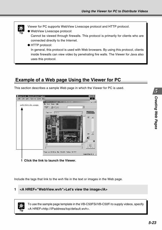
Creatin
g W
eb P
ages
5-23
Using the Viewer for PC to Distribute Videos
Include the tags that link to the wvh file in the text or images in the Web page.
1 <A HREF="WebView.wvh">Let's view the image</A>
1 Click the link to launch the Viewer.
Example of a Web page Using the Viewer for PC
This section describes a sample Web page in which the Viewer for PC is used.
Tip
To use the sample page template in the VB-C50FSi/VB-C50Fi to supply videos, specify
<A HREF=http://IPaddress/top/default.wvh>.
Tip
Viewer for PC supports WebView Livescope protocol and HTTP protocol.
WebView Livescope protocol:
Cannot be viewed through firewalls. This protocol is primarily for clients who are
connected directly to the Internet.
HTTP protocol:
In general, this protocol is used with Web browsers. By using this protocol, clients
inside firewalls can view video by penetrating fire walls. The Viewer for Java also
uses this protocol.
COPY
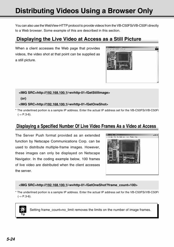
5-24
Distributing Videos Using a Browser Only
You can also use the WebView-HTTP protocol to provide videos from the VB-C50FSi/VB-C50Fi directly
to a Web browser. Some example of this are described in this section.
<IMG SRC=http://192.168.100.1/-wvhttp-01-/GetStillImage>
(or)
<IMG SRC=http://192.168.100.1/-wvhttp-01-/GetOneShot>
* The underlined portion is a sample IP address. Enter the actual IP address set for the VB-C50FSi/VB-C50Fi(→ P.3-6).
Tip
Setting frame_count=no_limit removes the limits on the number of image frames.
<IMG SRC=http://192.168.100.1/-wvhttp-01-/GetOneShot?frame_count=100>
* The underlined portion is a sample IP address. Enter the actual IP address set for the VB-C50FSi/VB-C50Fi(→ P.3-6).
Displaying the Live Video at Access as a Still Picture
When a client accesses the Web page that provides
videos, the video shot at that point can be supplied as
a still picture.
Displaying a Specified Number Of Live Video Frames As a Video at Access
The Server Push format provided as an extended
function by Netscape Communications Corp. can be
used to distribute multiple-frame images. However,
these images can only be displayed on Netscape
Navigator. In the coding example below, 100 frames
of live video are distributed when the client accesses
the server.COPY
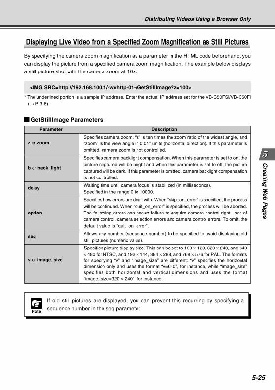
Creatin
g W
eb P
ages
5-25
GetStillImage Parameters
Parameter Description
z or zoomSpecifies camera zoom. “z” is ten times the zoom ratio of the widest angle, and“zoom” is the view angle in 0.01° units (horizontal direction). If this parameter isomitted, camera zoom is not controlled.
b or back_light
Specifies camera backlight compensation. When this parameter is set to on, thepicture captured will be bright and when this parameter is set to off, the picturecaptured will be dark. If this parameter is omitted, camera backlight compensationis not controlled.
delay Waiting time until camera focus is stabilized (in milliseconds).Specified in the range 0 to 10000.
option
Specifies how errors are dealt with. When “skip_on_error” is specified, the processwill be continued. When “quit_on_error” is specified, the process will be aborted.The following errors can occur: failure to acquire camera control right, loss ofcamera control, camera selection errors and camera control errors. To omit, thedefault value is “quit_on_error”.
seq Allows any number (sequence number) to be specified to avoid displaying oldstill pictures (numeric value).
v or image_size
Specifies picture display size. This can be set to 160 × 120, 320 × 240, and 640× 480 for NTSC, and 192 × 144, 384 × 288, and 768 × 576 for PAL. The formatsfor specifying “v” and “image_size” are different: “v” specifies the horizontaldimension only and uses the format “v=640”, for instance, while “image_size”specifies both horizontal and vertical dimensions and uses the format“image_size=320 × 240”, for instance.
Distributing Videos Using a Browser Only
Note
If old still pictures are displayed, you can prevent this recurring by specifying a
sequence number in the seq parameter.
<IMG SRC=http://192.168.100.1/-wvhttp-01-/GetStillImage?z=100>
* The underlined portion is a sample IP address. Enter the actual IP address set for the VB-C50FSi/VB-C50Fi(→ P.3-6).
Displaying Live Video from a Specified Zoom Magnification as Still Pictures
By specifying the camera zoom magnification as a parameter in the HTML code beforehand, you
can display the picture from a specified camera zoom magnification. The example below displays
a still picture shot with the camera zoom at 10x.
COPY
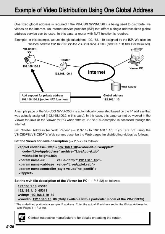
5-26Note
Contact respective manufacturers for details on setting the router.
One fixed global address is required if the VB-C50FSi/VB-C50Fi is being used to distribute live
videos on the Internet. An Internet service provider (ISP) that offers a single-address fixed global
address service can be used. In this case, a router with NAT function is required.
Example: In this example, we use the global address 192.168.1.10 assigned by the ISP. We also setthe local address 192.168.100.2 in the VB-C50FSi/VB-C50Fi (and 192.168.100.1 for the router).
Example of Video Distribution Using One Global Address
A sample page of the VB-C50FSi/VB-C50Fi is automatically generated based on the IP address thatwas actually assigned (192.168.100.2 in this case). In this case, this page cannot be viewed in theViewer for Java or the Viewer for PC when “http://192.168.100.2/sample/” is accessed through theInternet.
Set “Global Address for Web Pages” (→ P.3-16) to 192.168.1.10. If you are not using theVB-C50FSi/VB-C50Fi’s Web server, describe the Web pages for distributing videos as follows:
Set the Viewer for Java description (→ P.5-7) as follows:
<applet codebase=”http:// 192.168.1.10/-wvdoc-01-/LiveApplet/” code=”LiveApplet.class” archive=”LiveApplet.zip” width=450 height=380> <param name=url value=”http:// 192.168.1.10/”> <param name=cabbase value=”LiveApplet.cab”> <param name=controller_style value="no_pantilt"> </applet>
Set the wvh file description of the Viewer for PC (→ P.5-22) as follows:
192.168.1.10 65310192.168.1.10 65311wvhttp: 192.168.1.10 80wvaudio: 192.168.1.10 80 (Only available with a particular model of the VB-C50FSi)
* The underlined portion is a sample IP address. Enter the actual IP address set for the Global Address forWeb Pages (→ P.3-16).
Internet
Router
Viewer PC
Web server
Global address192.168.1.10
Add support for private address 192.168.100.2 (router NAT function).
192.168.100.2
192.168.100.1
VB-C50FSi
COPY
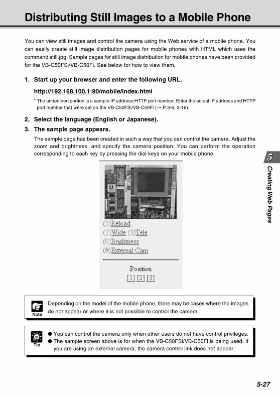
Creatin
g W
eb P
ages
5-27
You can view still images and control the camera using the Web service of a mobile phone. You
can easily create still image distribution pages for mobile phones with HTML which uses the
command still.jpg. Sample pages for still image distribution for mobile phones have been provided
for the VB-C50FSi/VB-C50Fi. See below for how to view them.
Distributing Still Images to a Mobile Phone
Tip
You can control the camera only when other users do not have control privileges. The sample screen above is for when the VB-C50FSi/VB-C50Fi is being used. If
you are using an external camera, the camera control link does not appear.
Note
Depending on the model of the mobile phone, there may be cases where the images
do not appear or where it is not possible to control the camera.
1. Start up your browser and enter the following URL.
http://192.168.100.1:80/mobile/index.html
* The underlined portion is a sample IP address:HTTP port number. Enter the actual IP address and HTTPport number that were set on the VB-C50FSi/VB-C50Fi (→ P.3-6, 3-16).
2. Select the language (English or Japanese).
3. The sample page appears.
The sample page has been created in such a way that you can control the camera. Adjust thezoom and brightness, and specify the camera position. You can perform the operationcorresponding to each key by pressing the dial keys on your mobile phone.
COPY
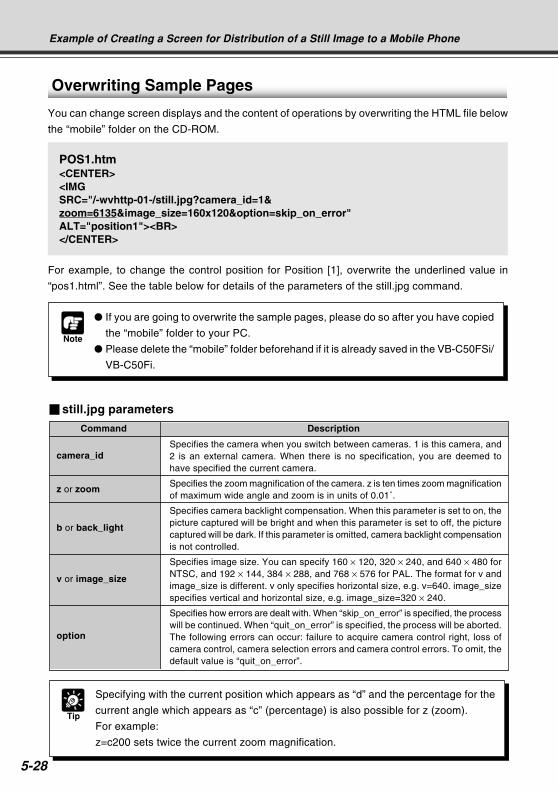
5-28
Example of Creating a Screen for Distribution of a Still Image to a Mobile Phone
Overwriting Sample Pages
You can change screen displays and the content of operations by overwriting the HTML file below
the “mobile” folder on the CD-ROM.
POS1.htm<CENTER><IMGSRC="/-wvhttp-01-/still.jpg?camera_id=1&zoom=6135&image_size=160x120&option=skip_on_error"ALT="position1"><BR></CENTER>
For example, to change the control position for Position [1], overwrite the underlined value in
“pos1.html”. See the table below for details of the parameters of the still.jpg command.
Note
If you are going to overwrite the sample pages, please do so after you have copied
the “mobile” folder to your PC.
Please delete the “mobile” folder beforehand if it is already saved in the VB-C50FSi/
VB-C50Fi.
still.jpg parameters
Command Description
camera_idSpecifies the camera when you switch between cameras. 1 is this camera, and2 is an external camera. When there is no specification, you are deemed tohave specified the current camera.
z or zoomSpecifies the zoom magnification of the camera. z is ten times zoom magnificationof maximum wide angle and zoom is in units of 0.01˚.
b or back_light
Specifies camera backlight compensation. When this parameter is set to on, thepicture captured will be bright and when this parameter is set to off, the picturecaptured will be dark. If this parameter is omitted, camera backlight compensationis not controlled.
v or image_size
Specifies image size. You can specify 160 × 120, 320 × 240, and 640 × 480 forNTSC, and 192 × 144, 384 × 288, and 768 × 576 for PAL. The format for v andimage_size is different. v only specifies horizontal size, e.g. v=640. image_sizespecifies vertical and horizontal size, e.g. image_size=320 × 240.
option
Specifies how errors are dealt with. When “skip_on_error” is specified, the processwill be continued. When “quit_on_error” is specified, the process will be aborted.The following errors can occur: failure to acquire camera control right, loss ofcamera control, camera selection errors and camera control errors. To omit, thedefault value is “quit_on_error”.
Tip
Specifying with the current position which appears as “d” and the percentage for the
current angle which appears as “c” (percentage) is also possible for z (zoom).
For example:
z=c200 sets twice the current zoom magnification.
COPY
Using the PictureRecording Function
This chapter describes a couple of specific examples of the
Picture Recording function using the VB-C50FSi/VB-C50Fi.
Still images and audio files can be automatically recorded
using input from an external device, motion detection or
schedule settings.
Chapter
COPY
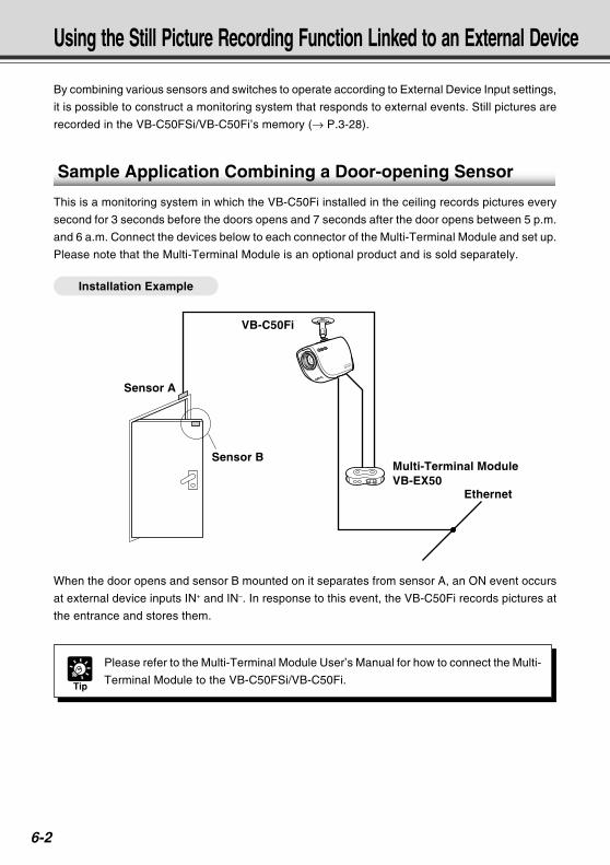
6-2
Using the Still Picture Recording Function Linked to an External Device
By combining various sensors and switches to operate according to External Device Input settings,
it is possible to construct a monitoring system that responds to external events. Still pictures are
recorded in the VB-C50FSi/VB-C50Fi’s memory (→ P.3-28).
Sample Application Combining a Door-opening Sensor
This is a monitoring system in which the VB-C50Fi installed in the ceiling records pictures every
second for 3 seconds before the doors opens and 7 seconds after the door opens between 5 p.m.
and 6 a.m. Connect the devices below to each connector of the Multi-Terminal Module and set up.
Please note that the Multi-Terminal Module is an optional product and is sold separately.
Installation Example
When the door opens and sensor B mounted on it separates from sensor A, an ON event occurs
at external device inputs IN+ and IN–. In response to this event, the VB-C50Fi records pictures at
the entrance and stores them.
Tip
Please refer to the Multi-Terminal Module User’s Manual for how to connect the Multi-
Terminal Module to the VB-C50FSi/VB-C50Fi.
Sensor A
VB-C50Fi
Multi-Terminal ModuleVB-EX50
Ethernet
Sensor B
COPY
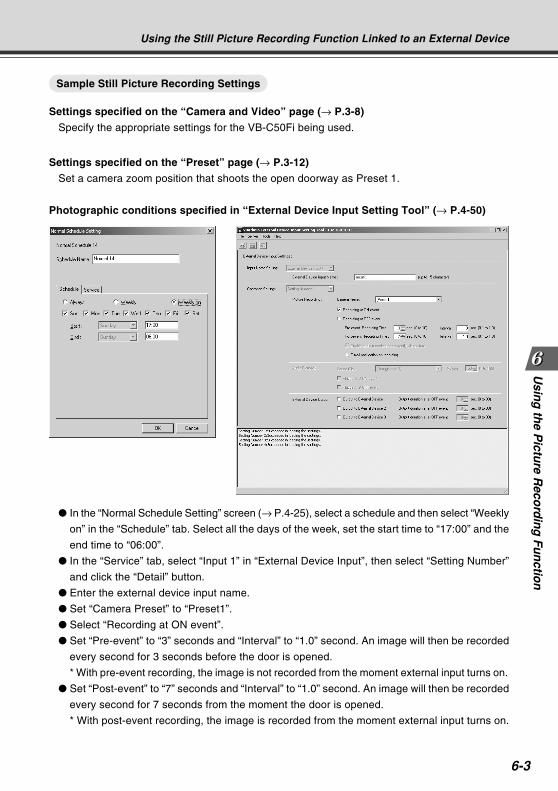
6-3
Usin
g th
e Pictu
re Reco
rdin
g F
un
ction
Using the Still Picture Recording Function Linked to an External Device
Sample Still Picture Recording Settings
Settings specified on the “Camera and Video” page (→ P.3-8)
Specify the appropriate settings for the VB-C50Fi being used.
Settings specified on the “Preset” page (→ P.3-12)
Set a camera zoom position that shoots the open doorway as Preset 1.
Photographic conditions specified in “External Device Input Setting Tool” (→ P.4-50)
In the “Normal Schedule Setting” screen (→ P.4-25), select a schedule and then select “Weekly
on” in the “Schedule” tab. Select all the days of the week, set the start time to “17:00” and the
end time to “06:00”.
In the “Service” tab, select “Input 1” in “External Device Input”, then select “Setting Number”
and click the “Detail” button.
Enter the external device input name.
Set “Camera Preset” to “Preset1”.
Select “Recording at ON event”.
Set “Pre-event” to “3” seconds and “Interval” to “1.0” second. An image will then be recorded
every second for 3 seconds before the door is opened.
* With pre-event recording, the image is not recorded from the moment external input turns on.
Set “Post-event” to “7” seconds and “Interval” to “1.0” second. An image will then be recorded
every second for 7 seconds from the moment the door is opened.
* With post-event recording, the image is recorded from the moment external input turns on.
COPY
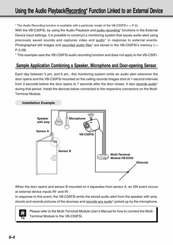
6-4
Using the Audio Playback/Recording* Function Linked to an External Device
* The Audio Recording function is available with a particular model of the VB-C50FSi (→ P.iii).
With the VB-C50FSi, by using the Audio Playback and audio recording* functions in the External
Device Input settings, it is possible to construct a monitoring system that issues audio alert using
previously saved sounds and captures video and audio* in response to external events.
Photographed still images and recorded audio files* are stored in the VB-C50FSi’s memory (→P.3-28)
* This example uses the VB-C50FSi audio recording function and does not apply to the VB-C50Fi.
Sample Application Combining a Speaker, Microphone and Door-opening Sensor
Each day between 5 pm. and 6 am., this monitoring system emits an audio alert whenever the
door opens and the VB-C50FSi mounted on the ceiling records images shot at 1-second intervals
from 3 seconds before the door opens to 7 seconds after the door closes. It also records audio*
during that period. Install the devices below connected to the respective connectors on the Multi-
Terminal Module.
Installation Example
When the door opens and sensor B mounted on it separates from sensor A, an ON event occurs
at external device inputs IN+ and IN–.
In response to this event, the VB-C50FSi emits the stored audio alert from the speaker with amp,
shoots and records pictures of the doorway and records any audio* picked up by the microphone.
Ethernet
Sensor A
Speaker with amp
Microphone
VB-C50FSi
Sensor BMulti-TerminalModule VB-EX50
Tip
Please refer to the Multi-Terminal Module User’s Manual for how to connect the Multi-
Terminal Module to the VB-C50FSi.
COPY
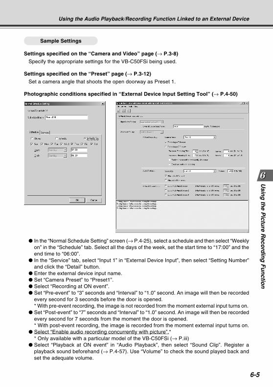
6-5
Usin
g th
e Pictu
re Reco
rdin
g F
un
ction
Using the Audio Playback/Recording Function Linked to an External Device
Sample Settings
Settings specified on the “Camera and Video” page (→ P.3-8)
Specify the appropriate settings for the VB-C50FSi being used.
Settings specified on the “Preset” page (→ P.3-12)
Set a camera angle that shoots the open doorway as Preset 1.
Photographic conditions specified in “External Device Input Setting Tool” (→ P.4-50)
In the “Normal Schedule Setting” screen (→ P.4-25), select a schedule and then select “Weeklyon” in the “Schedule” tab. Select all the days of the week, set the start time to “17:00” and theend time to “06:00”.
In the “Service” tab, select “Input 1” in “External Device Input”, then select “Setting Number”and click the “Detail” button.
Enter the external device input name. Set “Camera Preset” to “Preset1”. Select “Recording at ON event”. Set “Pre-event” to “3” seconds and “Interval” to “1.0” second. An image will then be recorded
every second for 3 seconds before the door is opened.* With pre-event recording, the image is not recorded from the moment external input turns on.
Set “Post-event” to “7” seconds and “Interval” to “1.0” second. An image will then be recordedevery second for 7 seconds from the moment the door is opened.* With post-event recording, the image is recorded from the moment external input turns on.
Select “Enable audio recording concurrently with picture”.** Only available with a particular model of the VB-C50FSi (→ P.iii)
Select “Playback at ON event” in “Audio Playback”, then select “Sound Clip”. Register aplayback sound beforehand (→ P.4-57). Use “Volume” to check the sound played back andset the adequate volume.
COPY
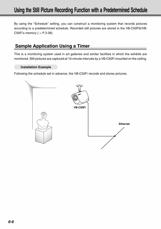
6-6
Using the Still Picture Recording Function with a Predetermined Schedule
By using the “Schedule” setting, you can construct a monitoring system that records pictures
according to a predetermined schedule. Recorded still pictures are stored in the VB-C50FSi/VB-
C50Fi’s memory (→ P.3-28).
Sample Application Using a Timer
This is a monitoring system used in art galleries and similar facilities in which the exhibits are
monitored. Still pictures are captured at 10-minute intervals by a VB-C50Fi mounted on the ceiling.
Installation Example
Following the schedule set in advance, the VB-C50Fi records and stores pictures.
Ethernet
VB-C50Fi
COPY
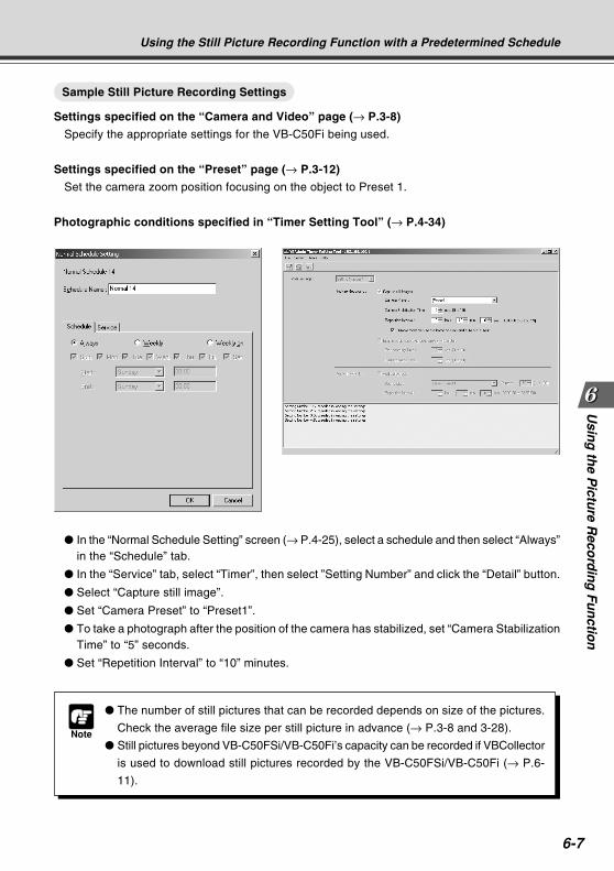
6-7
Usin
g th
e Pictu
re Reco
rdin
g F
un
ction
Using the Still Picture Recording Function with a Predetermined Schedule
Sample Still Picture Recording Settings
Settings specified on the “Camera and Video” page (→ P.3-8)
Specify the appropriate settings for the VB-C50Fi being used.
Settings specified on the “Preset” page (→ P.3-12)
Set the camera zoom position focusing on the object to Preset 1.
Photographic conditions specified in “Timer Setting Tool” (→ P.4-34)
Note
The number of still pictures that can be recorded depends on size of the pictures.
Check the average file size per still picture in advance (→ P.3-8 and 3-28).
Still pictures beyond VB-C50FSi/VB-C50Fi’s capacity can be recorded if VBCollector
is used to download still pictures recorded by the VB-C50FSi/VB-C50Fi (→ P.6-
11).
In the “Normal Schedule Setting” screen (→ P.4-25), select a schedule and then select “Always”in the “Schedule” tab.
In the “Service” tab, select “Timer”, then select ”Setting Number” and click the “Detail” button.
Select “Capture still image”.
Set “Camera Preset” to “Preset1”.
To take a photograph after the position of the camera has stabilized, set “Camera StabilizationTime” to “5” seconds.
Set “Repetition Interval” to “10” minutes.
COPY
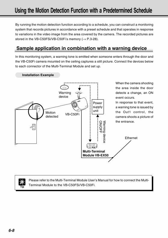
6-8
Using the Motion Detection Function with a Predetermined Schedule
By running the motion detection function according to a schedule, you can construct a monitoring
system that records pictures in accordance with a preset schedule and that operates in response
to variations in the video image from the area covered by the camera. The recorded pictures are
stored in the VB-C50FSi/VB-C50Fi’s memory (→ P.3-28).
Sample application in combination with a warning device
In this monitoring system, a warning tone is emitted when someone enters through the door and
the VB-C50Fi camera mounted on the ceiling captures a still picture. Connect the devices below
to each connector of the Multi-Terminal Module and set up.
Installation Example
When the camera shooting
the area inside the door
detects a change, an ON
event occurs.
In response to that event,
a warning tone is issued by
the Out1 control, the
camera shoots a picture of
the entrance.
Tip
Please refer to the Multi-Terminal Module User’s Manual for how to connect the Multi-
Terminal Module to the VB-C50FSi/VB-C50Fi.
Multi-TerminalModule VB-EX50
Ethernet
Motion detected
Warning device
VB-C50Fi
Powersupplyunit
Warning device
ON
/OF
F
COPY
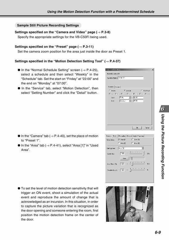
6-9
Usin
g th
e Pictu
re Reco
rdin
g F
un
ction
Sample Still Picture Recording Settings
Settings specified on the “Camera and Video” page (→ P.3-8)
Specify the appropriate settings for the VB-C50Fi being used.
Settings specified on the “Preset” page (→ P.3-11)
Set the camera zoom position for the area just inside the door as Preset 1.
Settings specified in the “Motion Detection Setting Tool” (→ P.4-37)
In the “Normal Schedule Setting” screen (→ P.4-25),select a schedule and then select “Weekly” in the“Schedule” tab. Set the start on “Friday” at “22:00” andthe end on “Monday” at “07:00”.
In the “Service” tab, select “Motion Detection”, thenselect “Setting Number” and click the “Detail” button.
In the “Camera” tab (→ P.4-40), set the place of motionto “Preset 1”.
In the “Area” tab (→ P.4-41), select “Area [1]” in “UsedArea”.
To set the level of motion detection sensitivity that willtrigger an ON event, shoot a simulation of the actualevent and reproduce the amount of change that isacknowledged as an incursion. In this situation, in orderto capture the picture variation that is recognized asthe door opening and someone entering the room, firstposition the motion detection frame on the center ofthe door.
Using the Motion Detection Function with a Predetermined Schedule
COPY
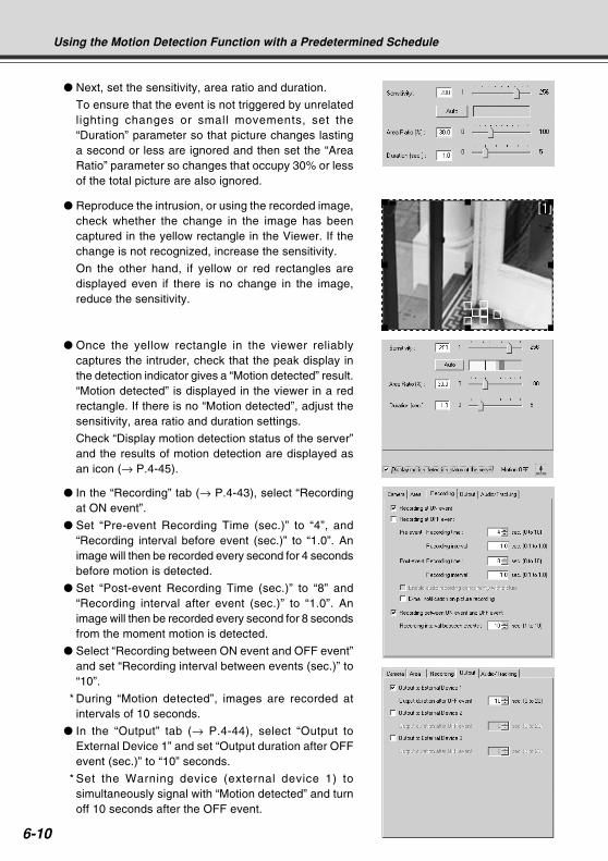
6-10
Next, set the sensitivity, area ratio and duration.
To ensure that the event is not triggered by unrelatedlighting changes or small movements, set the“Duration” parameter so that picture changes lastinga second or less are ignored and then set the “AreaRatio” parameter so changes that occupy 30% or lessof the total picture are also ignored.
Reproduce the intrusion, or using the recorded image,check whether the change in the image has beencaptured in the yellow rectangle in the Viewer. If thechange is not recognized, increase the sensitivity.
On the other hand, if yellow or red rectangles aredisplayed even if there is no change in the image,reduce the sensitivity.
Once the yellow rectangle in the viewer reliablycaptures the intruder, check that the peak display inthe detection indicator gives a “Motion detected” result.“Motion detected” is displayed in the viewer in a redrectangle. If there is no “Motion detected”, adjust thesensitivity, area ratio and duration settings.
Check “Display motion detection status of the server”and the results of motion detection are displayed asan icon (→ P.4-45).
In the “Recording” tab (→ P.4-43), select “Recordingat ON event”.
Set “Pre-event Recording Time (sec.)” to “4”, and“Recording interval before event (sec.)” to “1.0”. Animage will then be recorded every second for 4 secondsbefore motion is detected.
Set “Post-event Recording Time (sec.)” to “8” and“Recording interval after event (sec.)” to “1.0”. Animage will then be recorded every second for 8 secondsfrom the moment motion is detected.
Select “Recording between ON event and OFF event”and set “Recording interval between events (sec.)” to“10”.
* During “Motion detected”, images are recorded atintervals of 10 seconds.
In the “Output” tab (→ P.4-44), select “Output toExternal Device 1” and set “Output duration after OFFevent (sec.)” to “10” seconds.
* Set the Warning device (external device 1) tosimultaneously signal with “Motion detected” and turnoff 10 seconds after the OFF event.
Using the Motion Detection Function with a Predetermined Schedule
COPY
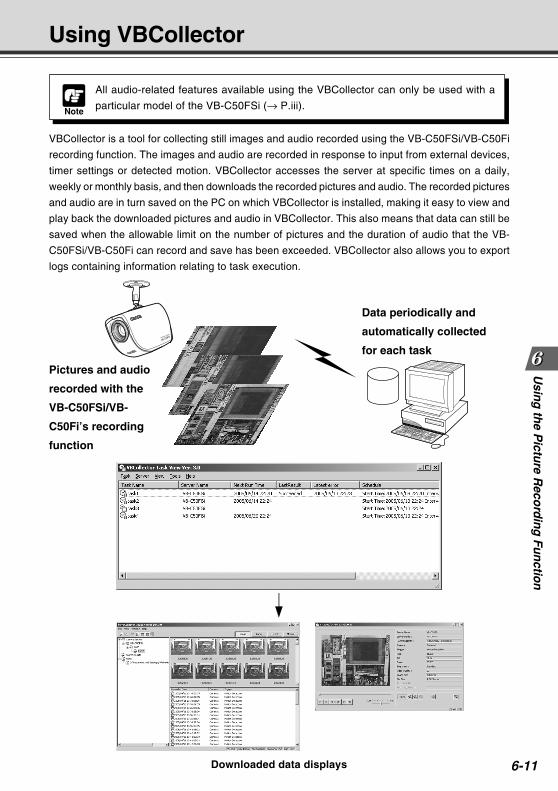
6-11
Usin
g th
e Pictu
re Reco
rdin
g F
un
ction
Using VBCollector
Downloaded data displays
Pictures and audio
recorded with the
VB-C50FSi/VB-
C50Fi’s recording
function
Data periodically and
automatically collected
for each task
VBCollector is a tool for collecting still images and audio recorded using the VB-C50FSi/VB-C50Fi
recording function. The images and audio are recorded in response to input from external devices,
timer settings or detected motion. VBCollector accesses the server at specific times on a daily,
weekly or monthly basis, and then downloads the recorded pictures and audio. The recorded pictures
and audio are in turn saved on the PC on which VBCollector is installed, making it easy to view and
play back the downloaded pictures and audio in VBCollector. This also means that data can still be
saved when the allowable limit on the number of pictures and the duration of audio that the VB-
C50FSi/VB-C50Fi can record and save has been exceeded. VBCollector also allows you to export
logs containing information relating to task execution.
Note
All audio-related features available using the VBCollector can only be used with a
particular model of the VB-C50FSi (→ P.iii).
COPY
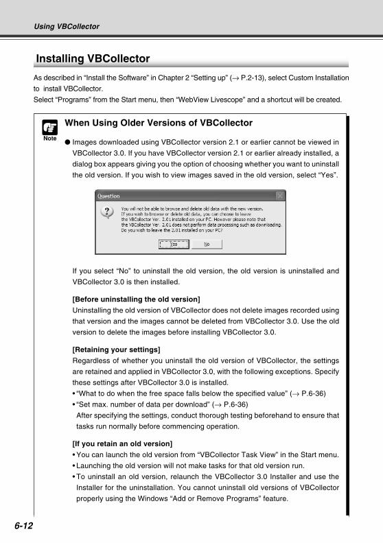
6-12
Using VBCollector
Installing VBCollector
As described in “Install the Software” in Chapter 2 “Setting up” (→ P.2-13), select Custom Installation
to install VBCollector.
Select “Programs” from the Start menu, then “WebView Livescope” and a shortcut will be created.
Note
When Using Older Versions of VBCollector
Images downloaded using VBCollector version 2.1 or earlier cannot be viewed in
VBCollector 3.0. If you have VBCollector version 2.1 or earlier already installed, a
dialog box appears giving you the option of choosing whether you want to uninstall
the old version. If you wish to view images saved in the old version, select “Yes”.
If you select “No” to uninstall the old version, the old version is uninstalled and
VBCollector 3.0 is then installed.
[Before uninstalling the old version]
Uninstalling the old version of VBCollector does not delete images recorded using
that version and the images cannot be deleted from VBCollector 3.0. Use the old
version to delete the images before installing VBCollector 3.0.
[Retaining your settings]
Regardless of whether you uninstall the old version of VBCollector, the settings
are retained and applied in VBCollector 3.0, with the following exceptions. Specify
these settings after VBCollector 3.0 is installed.
• “What to do when the free space falls below the specified value” (→ P.6-36)
• “Set max. number of data per download” (→ P.6-36)
After specifying the settings, conduct thorough testing beforehand to ensure that
tasks run normally before commencing operation.
[If you retain an old version]
• You can launch the old version from “VBCollector Task View” in the Start menu.
• Launching the old version will not make tasks for that old version run.
• To uninstall an old version, relaunch the VBCollector 3.0 Installer and use the
Installer for the uninstallation. You cannot uninstall old versions of VBCollector
properly using the Windows “Add or Remove Programs” feature.
COPY
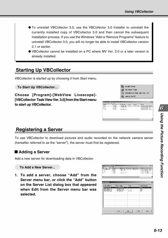
6-13
Usin
g th
e Pictu
re Reco
rdin
g F
un
ction
Using VBCollector
To uninstall VBCollector 3.0, use the VBCollector 3.0 Installer to uninstall the
currently installed copy of VBCollector 3.0 and then cancel the subsequent
installation process. If you use the Windows “Add or Remove Programs” feature to
uninstall VBCollector 3.0, you will no longer be able to install VBCollector version
2.1 or earlier.
VBCollector cannot be installed on a PC where MV Ver. 2.0 or a later version is
already installed.
Starting Up VBCollector
VBCollector is started up by choosing it from Start menu.
To Start Up VBCollector...
Choose [Program]-[WebView Livescope]-[VBCollector Task View Ver. 3.0] from the Start menuto start up VBCollector.
Registering a Server
To use VBCollector to download pictures and audio recorded on the network camera server
(hereafter referred to as the “server”), the server must first be registered.
Adding a Server
Add a new server for downloading data in VBCollector.
To Add a New Server...
1. To add a server, choose “Add” from theServer menu bar, or click the “Add” buttonon the Server List dialog box that appearedwhen Edit from the Server menu bar wasselected.
COPY
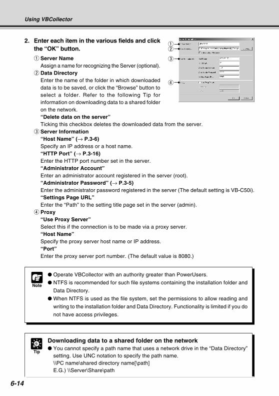
6-14
Using VBCollector
Note
Operate VBCollector with an authority greater than PowerUsers.
NTFS is recommended for such file systems containing the installation folder and
Data Directory.
When NTFS is used as the file system, set the permissions to allow reading and
writing to the installation folder and Data Directory. Functionality is limited if you do
not have access privileges.
2. Enter each item in the various fields and clickthe “OK” button.
q Server NameAssign a name for recognizing the Server (optional).
w Data DirectoryEnter the name of the folder in which downloadeddata is to be saved, or click the “Browse” button toselect a folder. Refer to the following Tip forinformation on downloading data to a shared folderon the network.“Delete data on the server”Ticking this checkbox deletes the downloaded data from the server.
e Server Information“Host Name” (→ P.3-6)Specify an IP address or a host name.“HTTP Port” (→ P.3-16)Enter the HTTP port number set in the server.“Administrator Account”Enter an administrator account registered in the server (root).“Administrator Password” (→ P.3-5)Enter the administrator password registered in the server (The default setting is VB-C50i).“Settings Page URL”Enter the “Path” to the setting title page set in the server (admin).
r Proxy“Use Proxy Server”Select this if the connection is to be made via a proxy server.“Host Name”Specify the proxy server host name or IP address.“Port”Enter the proxy server port number. (The default value is 8080.)
qw
e
r
Tip
Downloading data to a shared folder on the network You cannot specify a path name that uses a network drive in the “Data Directory”
setting. Use UNC notation to specify the path name.\\PC name\shared directory name[\path]E.G.) \\Server\Share\path
COPY
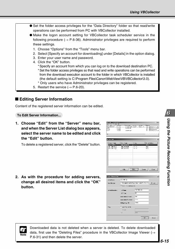
6-15
Usin
g th
e Pictu
re Reco
rdin
g F
un
ction
Using VBCollector
Note
Downloaded data is not deleted when a server is deleted. To delete downloadeddata, first use the “Deleting Files” procedure in the VBCollector Image Viewer (→P.6-31) and then delete the server.
Editing Server Information
Content of the registered server information can be edited.
To Edit Server Information...
1. Choose “Edit” from the “Server” menu bar,and when the Server List dialog box appears,select the server name to be edited and clickthe “Edit” button.
To delete a registered server, click the “Delete” button.
2. As with the procedure for adding servers,change all desired items and click the “OK”button.
Set the folder access privileges for the “Data Directory” folder so that read/writeoperations can be performed from PC with VBCollector installed.
Make the logon account setting for VBCollector task scheduler service in thefollowing procedure (→ P.6-36). Administrator privileges are required to performthese settings.
1. Choose “Options” from the “Tools” menu bar.2. Select [Specify an account for downloading] under [Details] in the option dialog.3. Enter your user name and password.4. Click the “OK” button.
*Specify an account from which you can log on to the download destination PC.*Set the folder access privileges so that read and write operations can be performedfrom the download execution account to the folder in which VBCollector is installed(the default setting is C:\Program Files\Canon\WebView\VB\VBCollector\3.0).
* Only users who have Administrator privileges can be registered.5. Restart the service (→ P.6-20).
COPY
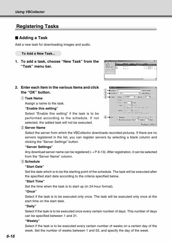
6-16
Using VBCollector
2. Enter each item in the various items and clickthe “OK” button.
q Task Name
Assign a name to the task.
“Enable this setting”
Select “Enable this setting” if the task is to beperformed according to the schedule. If notselected, the added task will not be executed.
w Server Name
Select the server from which the VBCollector downloads recorded pictures. If there are noservers registered in the list, you can register servers by selecting a blank column andclicking the “Server Settings” button.
“Server Settings”
Any download server name can be registered (→ P.6-13). After registration, it can be selectedfrom the “Server Name” column.
e Schedule
“Start Date”
Set the date which is to be the starting point of the schedule. The task will be executed afterthe specified start date according to the criteria specified below.
“Start Time”
Set the time when the task is to start up (in 24-hour format).
“Once”
Select if the task is to be executed only once. The task will be executed only once at thestart time on the start date.
“Daily”
Select if the task is to be executed once every certain number of days. This number of dayscan be specified between 1 and 31.
“Weekly”
Select if the task is to be executed every certain number of weeks on a certain day of theweek. Set the number of weeks between 1 and 53, and specify the day of the week.
Registering Tasks
Adding a Task
Add a new task for downloading images and audio.
To Add a New Task...
1. To add a task, choose “New Task” from the“Task” menu bar.
qwe
r
COPY
6-17
Usin
g th
e Pictu
re Reco
rdin
g F
un
ction
Using VBCollector
Note
Up to 16 tasks can be executed by VBCollector simultaneously. Please be sure
not to load a schedule with 17 or more tasks to be executed. VBCollector is also
not able to execute multiple tasks simultaneously to the same server. Please take
care to ensure that multiple tasks are not executed to the same server by taking
such measures as leaving a sufficient time space between the “Start Time” of each
task.
If you execute a maximum of 16 tasks simultaneously, please confirm performance
of the PC on which VBCollector is installed (→ P.1-5).
When Log S015 “The task was running longer than the execution interval.” is
reported, review the settings for the schedules such as reducing the number of
tasks to be performed at the same time. If you use Windows 2000 SP4, try
performing a Windows Update as it may improve the performance.
“Monthly”
Select if the task is to be executed every month on a certain day of the month. Set this daybetween 1 and 31. Or a day of the week for a certain week of the month can also bespecified.
r Details
“Repeat task”
Select if task is to be executed in repetition in time units. Downloads occur in repetition onlyfor the specified number of times at specified intervals starting from the start time specifiedin the schedule. If not selected, download occurs once at the start time specified in theschedule. Once the End Time is reached, the task is not performed. Data can be downloadedat intervals of some minutes or by specifying a number. Enter a value between 5 and 1439as the number of minutes. Times up to the Start Time plus 23:59 can be specified as theEnd Time.
“Retry when an error occurs”
Select this item if a task is to be executed again in the event a download does not endnormally after a task is executed. The task will be executed again a specified number oftimes at specified time intervals. During this time, if the download is completed normally,further tasks will not be repeated. Specify the number of times and the time interval atwhich a task is to be re-executed. For the number of times, enter a value between 1 and 10;for the interval, enter a value between 1 and 10.
COPY
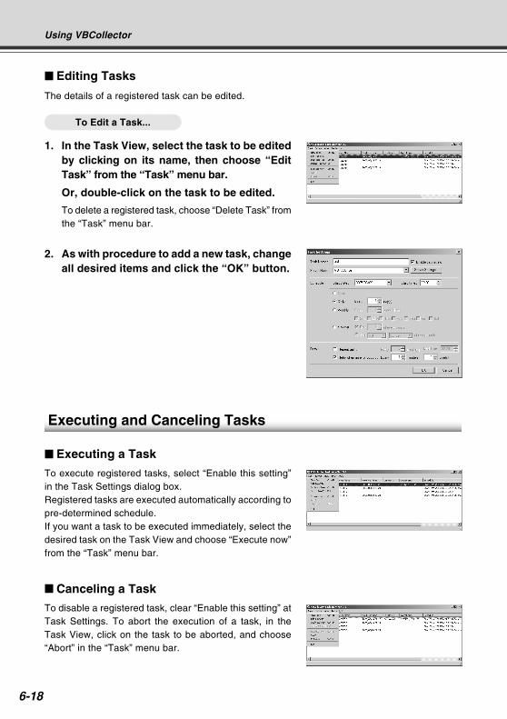
6-18
Using VBCollector
Editing Tasks
The details of a registered task can be edited.
To Edit a Task...
1. In the Task View, select the task to be editedby clicking on its name, then choose “EditTask” from the “Task” menu bar.
Or, double-click on the task to be edited.
To delete a registered task, choose “Delete Task” fromthe “Task” menu bar.
Executing and Canceling Tasks
Executing a Task
To execute registered tasks, select “Enable this setting”in the Task Settings dialog box.Registered tasks are executed automatically according topre-determined schedule.If you want a task to be executed immediately, select thedesired task on the Task View and choose “Execute now”from the “Task” menu bar.
Canceling a Task
To disable a registered task, clear “Enable this setting” atTask Settings. To abort the execution of a task, in theTask View, click on the task to be aborted, and choose“Abort” in the “Task” menu bar.
2. As with procedure to add a new task, changeall desired items and click the “OK” button.
COPY
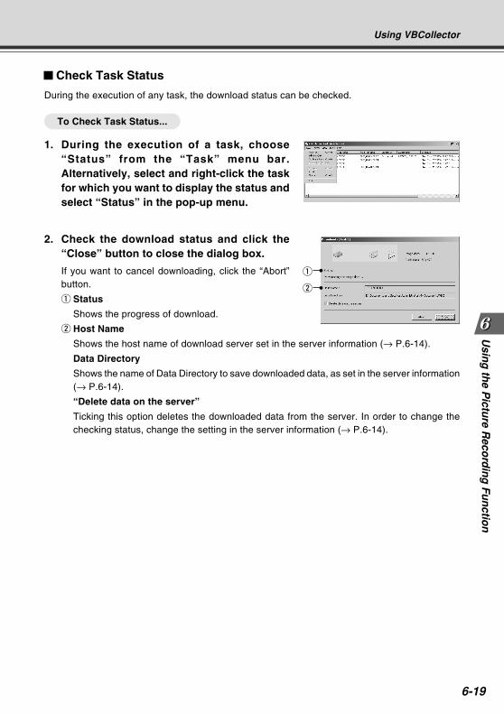
6-19
Usin
g th
e Pictu
re Reco
rdin
g F
un
ction
Using VBCollector
2. Check the download status and click the“Close” button to close the dialog box.
If you want to cancel downloading, click the “Abort”button.
q Status
Shows the progress of download.
w Host Name
Shows the host name of download server set in the server information (→ P.6-14).
Data Directory
Shows the name of Data Directory to save downloaded data, as set in the server information(→ P.6-14).
“Delete data on the server”
Ticking this option deletes the downloaded data from the server. In order to change thechecking status, change the setting in the server information (→ P.6-14).
Check Task Status
During the execution of any task, the download status can be checked.
To Check Task Status...
1. During the execution of a task, choose“Status” from the “Task” menu bar.Alternatively, select and right-click the taskfor which you want to display the status andselect “Status” in the pop-up menu.
q
w
COPY
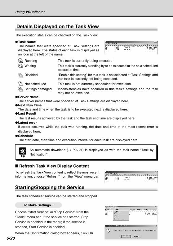
6-20
Using VBCollector
Starting/Stopping the Service
The task scheduler service can be started and stopped.
To Make Settings...
Choose “Start Service” or “Stop Service” from the
“Tools” menu bar. If the service has started, Stop
Service is enabled in the menu; if the service is
stopped, Start Service is enabled.
When the Confirmation dialog box appears, click OK.
Details Displayed on the Task View
The execution status can be checked on the Task View.
Task NameThe names that were specified at Task Settings aredisplayed here. The status of each task is displayed asan icon at the left of the name.
Running This task is currently being executed.
Waiting This task is currently standing by to be executed at the next scheduledexecution time.
Disabled “Enable this setting” for this task is not selected at Task Settings andthis task is currently not being executed.
Not scheduled This task is not currently scheduled for execution.
Settings damaged Inconsistencies have occurred in this task’s settings and the taskmay not be executed.
Server NameThe server names that were specified at Task Settings are displayed here.
Next Run TimeThe date and time when the task is to be executed next is displayed here.
Last ResultThe last results achieved by the task and the task end time are displayed here.
Latest errorIf errors occurred while the task was running, the date and time of the most recent error isdisplayed here.
ScheduleThe start date, start time and execution interval for each task are displayed here.
Refresh Task View Display ContentTo refresh the Task View content to reflect the most recentinformation, choose “Refresh” from the “View” menu bar.
Tip
An automatic download (→ P.6-21) is displayed as with the task name “Task byNotification”.CO
PY
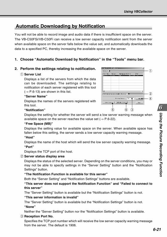
6-21
Usin
g th
e Pictu
re Reco
rdin
g F
un
ction
Using VBCollector
Automatic Downloading by Notification
You will not be able to record image and audio data if there is insufficient space on the server.
The VB-C50FSi/VB-C50Fi can receive a low server capacity notification sent from the server
when available space on the server falls below the value set, and automatically downloads the
data to a specified PC, thereby increasing the available space on the server.
1. Choose “Automatic Download by Notification” in the “Tools” menu bar.
2. Perform the settings relating to notification.
q Server ListDisplays a list of the servers from which the datacan be downloaded. The settings relating tonotification of each server registered with this tool(→ P.6-13) are shown in this list.
“Server Name”
Displays the names of the servers registered withthis tool.
“Notification”Displays the setting for whether the server will send a low server warning message whenavailable space on the server reaches the value set (→ P.6-22).
“Free Space (MB)”
Displays the setting value for available space on the server. When available space hasfallen below this setting, the server sends a low server capacity warning message.
“Host”Displays the name of the host which will send the low server capacity warning message.
“Port”Displays the TCP port of the host.
w Server status display area
Displays the status of the selected server. Depending on the server conditions, you may ormay not be able to specify settings in the “Server Setting” button and the “NotificationSettings” button.
“The Notification Function is available for this server”Both the “Server Setting” and “Notification Settings” buttons are available.
“This server does not support the Notification Function” and “Failed to connect tothis server”The “Server Setting” button is available but the “Notification Settings” button is not.
“This server information is invalid”
The “Server Setting” button is available but the “Notification Settings” button is not.
“None”Neither the “Server Setting” button nor the “Notification Settings” button is available.
e Reception Port No.Specifies the TCP port number which will receive the low server capacity warning messagefrom the server. The default is 1906.
q
w
r
y et
COPY
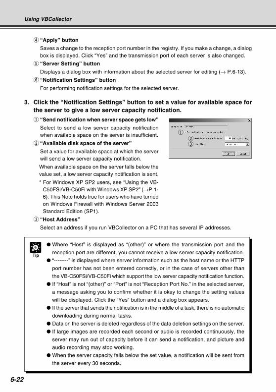
6-22
r “Apply” button
Saves a change to the reception port number in the registry. If you make a change, a dialogbox is displayed. Click “Yes” and the transmission port of each server is also changed.
t “Server Setting” button
Displays a dialog box with information about the selected server for editing (→ P.6-13).
y “Notification Settings” button
For performing notification settings for the selected server.
3. Click the “Notification Settings” button to set a value for available space forthe server to give a low server capacity notification.
q “Send notification when server space gets low”
Select to send a low server capacity notificationwhen available space on the server is insufficient.
w “Available disk space of the server”
Set a value for available space at which the serverwill send a low server capacity notification.
When available space on the server falls below thevalue set, a low server capacity notification is sent.
* For Windows XP SP2 users, see “Using the VB-C50FSi/VB-C50Fi with Windows XP SP2” (→P.1-6). This Note holds true for users who have turnedon Windows Firewall with Windows Server 2003Standard Edition (SP1).
e “Host Address”
Select an address if you run VBCollector on a PC that has several IP addresses.
Using VBCollector
Tip
Where “Host” is displayed as “(other)” or where the transmission port and the
reception port are different, you cannot receive a low server capacity notification.
“--------” is displayed where server information such as the host name or the HTTP
port number has not been entered correctly, or in the case of servers other than
the VB-C50FSi/VB-C50Fi which support the low server capacity notification function.
If “Host” is not “(other)” or “Port” is not “Reception Port No.” in the selected server,
a message asking you to confirm whether it is okay to change the setting values
will be displayed. Click the “Yes” button and a dialog box appears.
If the server that sends the notification is in the middle of a task, there is no automatic
downloading during normal tasks.
Data on the server is deleted regardless of the data deletion settings on the server.
If large images are recorded each second or audio is recorded continuously, the
server may run out of capacity before it can send a notification, and picture and
audio recording may stop working.
When the server capacity falls below the set value, a notification will be sent from
the server every 30 seconds.
qwe
COPY
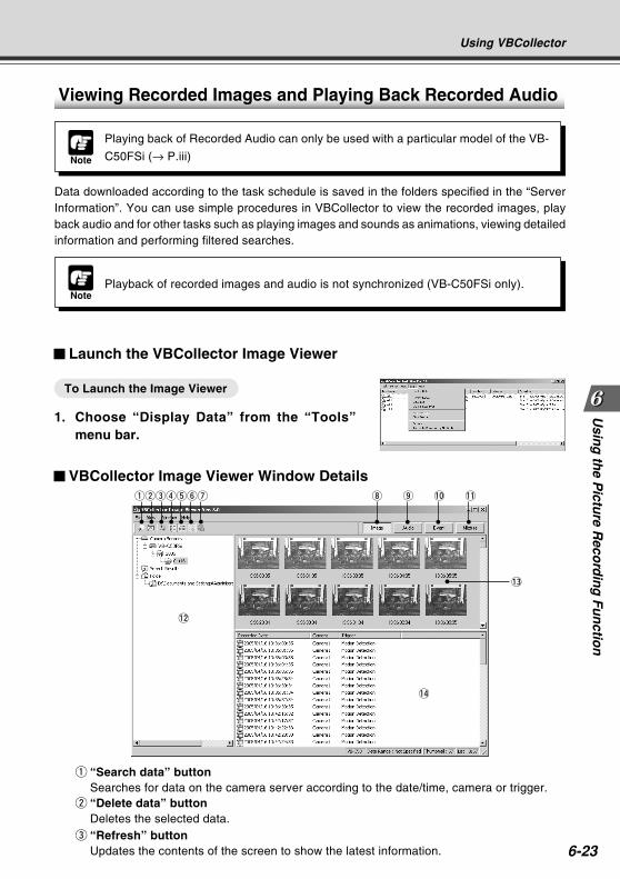
6-23
Usin
g th
e Pictu
re Reco
rdin
g F
un
ction
Using VBCollector
q “Search data” buttonSearches for data on the camera server according to the date/time, camera or trigger.
w “Delete data” buttonDeletes the selected data.
e “Refresh” buttonUpdates the contents of the screen to show the latest information.
Viewing Recorded Images and Playing Back Recorded Audio
Launch the VBCollector Image Viewer
To Launch the Image Viewer
1. Choose “Display Data” from the “Tools”menu bar.
VBCollector Image Viewer Window Detailsqwertyu
NotePlayback of recorded images and audio is not synchronized (VB-C50FSi only).
i o !0 !1
!3
!4
!2
Data downloaded according to the task schedule is saved in the folders specified in the “ServerInformation”. You can use simple procedures in VBCollector to view the recorded images, playback audio and for other tasks such as playing images and sounds as animations, viewing detailedinformation and performing filtered searches.
Note
Playing back of Recorded Audio can only be used with a particular model of the VB-
C50FSi (→ P.iii)
COPY
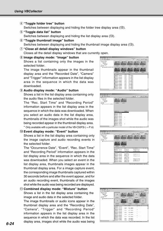
6-24
Using VBCollector
r “Toggle folder tree” buttonSwitches between displaying and hiding the folder tree display area (! 2).
t “Toggle data list” buttonSwitches between displaying and hiding the list display area (!4).
y “Toggle thumbnail image” buttonSwitches between displaying and hiding the thumbnail image display area (!3).
u “Close all detail display windows” buttonCloses all the detail display windows that are currently open.
i Image display mode: “Image” buttonShows a list containing only the images in theselected folder.The image thumbnails appear in the thumbnaildisplay area and the “Recorded Date”, “Camera”and “Trigger” information appears in the list displayarea in the sequence in which the data wasdownloaded.
o Audio display mode: “Audio” buttonShows a list in the list display area containing onlythe audio files in the selected folder.The “Rec. Start Time” and “Recording Period”information appears in the list display area in thesequence in which the data was downloaded. Whenyou select an audio data in the list display area,thumbnails of the images shot while the audio wasbeing recorded appear in the thumbnail display area.* Only available with a particular model of the VB-C50FSi (→ P.iii)
!0 Event display mode: “Event” buttonShows a list in the list display area containing onlythe image capture and audio recording events inthe selected folder.The “Occurrence Date”, “Event”, “Rec. Start Time”and “Recording Period” information appears in thelist display area in the sequence in which the datawas downloaded. When you select an event in thelist display area, thumbnails images appear in thethumbnail display area. For a image capture event,the corresponding image thumbnails captured within30 seconds before and after the event appear, and foran audio recording event, thumbnails of the imagesshot while the audio was being recorded are displayed.
!1 Combined display mode: “Mixture” buttonShows a list in the list display area containing theimage and audio data in the selected folder.The image thumbnails or audio icons appear in thethumbnail display area and the “Recording Date”,“Camera”, “Trigger” and “Recording Period”information appears in the list display area in thesequence in which the data was recorded. In the listdisplay area, images shot while the audio was being
COPY
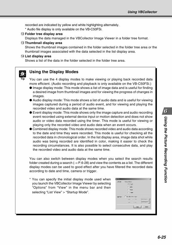
6-25
Usin
g th
e Pictu
re Reco
rdin
g F
un
ction
recorded are indicated by yellow and white highlighting alternately.* Audio file display is only available on the VB-C50FSi.
!2 Folder tree display areaDisplays the data managed in the VBCollector Image Viewer in a folder tree format.
!3 Thumbnail display areaShows the thumbnail images contained in the folder selected in the folder tree area or thethumbnail images associated with the data selected in the list display area.
!4 List display areaShows a list of the data in the folder selected in the folder tree area.
Using VBCollector
Tip
Using the Display Modes
You can use the 4 display modes to make viewing or playing back recorded datamore efficient. (Audio recording and playback is only available on the VB-C50FSi.) Image display mode: This mode shows a list of image data and is useful for finding
a desired image from thumbnail images and for viewing the progress of changes inimages.
Audio display mode: This mode shows a list of audio data and is useful for viewingimages captured during a period of audio event, and for viewing and playing therecorded video and audio data at the same time.
Event display mode: This mode shows only the image capture and audio recordingevent recorded using external device input or motion detection and does not showaudio or video data recorded using the timer. This mode is useful for viewing orplaying only the recorded video and audio data when an event occurs.
Combined display mode: This mode shows recorded video and audio data accordingto the date and time they were recorded. This mode is useful for checking all therecorded data in chronological order. In the list display area, image data shot whileaudio was being recorded are identified in color, making it easier to check therecording circumstances. It is also possible to select consecutive data, and playthe recorded video and audio data at the same time.
You can also switch between display modes when you select the search resultsfolder created during a search (→ P.6-28) and view the contents as a list. The differentdisplay modes can be used to good effect after you have filtered the recorded dataaccording to date and time, camera or trigger.
* You can specify the initial display mode used whenyou launch the VBCollector Image Viewer by selecting“Options” from “View” in the menu bar and thenselecting “List View” > “Startup Mode”.
COPY
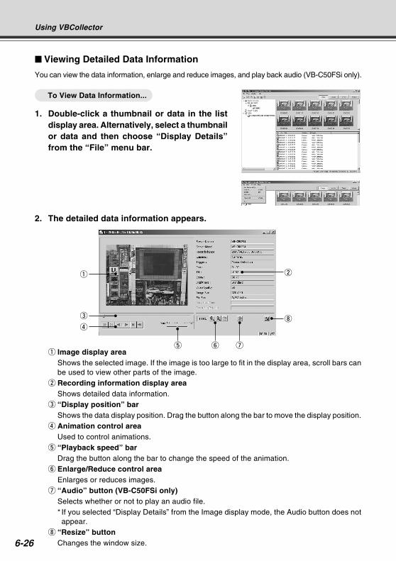
6-26
Using VBCollector
2. The detailed data information appears.
q Image display areaShows the selected image. If the image is too large to fit in the display area, scroll bars canbe used to view other parts of the image.
w Recording information display areaShows detailed data information.
e “Display position” barShows the data display position. Drag the button along the bar to move the display position.
r Animation control areaUsed to control animations.
t “Playback speed” barDrag the button along the bar to change the speed of the animation.
y Enlarge/Reduce control areaEnlarges or reduces images.
u “Audio” button (VB-C50FSi only)Selects whether or not to play an audio file.* If you selected “Display Details” from the Image display mode, the Audio button does notappear.
i “Resize” buttonChanges the window size.
yt u
w
i
q
e
r
Viewing Detailed Data Information
You can view the data information, enlarge and reduce images, and play back audio (VB-C50FSi only).
To View Data Information...
1. Double-click a thumbnail or data in the listdisplay area. Alternatively, select a thumbnailor data and then choose “Display Details”from the “File” menu bar.
COPY
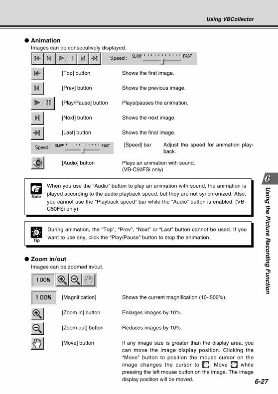
6-27
Usin
g th
e Pictu
re Reco
rdin
g F
un
ction
Using VBCollector
Zoom in/outImages can be zoomed in/out.
[Magnification] Shows the current magnification (10~500%).
[Zoom in] button Enlarges images by 10%.
[Zoom out] button Reduces images by 10%.
[Move] button If any image size is greater than the display area, youcan move the image display position. Clicking the“Move” button to position the mouse cursor on theimage changes the cursor to . Move whilepressing the left mouse button on the image. The imagedisplay position will be moved.
AnimationImages can be consecutively displayed.
[Top] button Shows the first image.
[Prev] button Shows the previous image.
[Play/Pause] button Plays/pauses the animation.
[Next] button Shows the next image.
[Last] button Shows the final image.
[Speed] bar Adjust the speed for animation play-back.
[Audio] button Plays an animation with sound.(VB-C50FSi only)
Tip
During animation, the “Top”, “Prev”, “Next” or “Last” button cannot be used. If you
want to use any, click the “Play/Pause” button to stop the animation.
Note
When you use the “Audio” button to play an animation with sound, the animation is
played according to the audio playback speed, but they are not synchronized. Also,
you cannot use the “Playback speed” bar while the “Audio” button is enabled. (VB-C50FSi only)
COPY
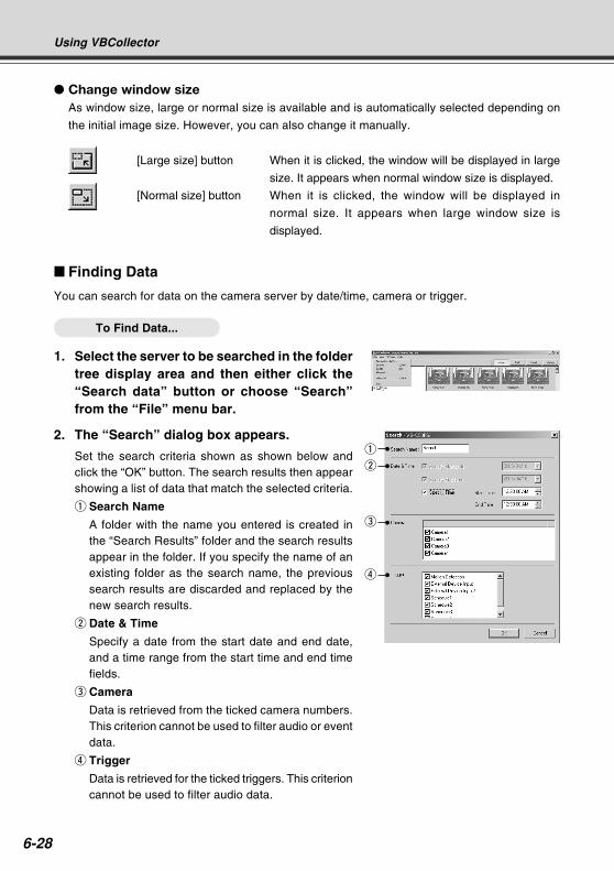
6-28
Using VBCollector
Change window sizeAs window size, large or normal size is available and is automatically selected depending on
the initial image size. However, you can also change it manually.
[Large size] button When it is clicked, the window will be displayed in large
size. It appears when normal window size is displayed.
[Normal size] button When it is clicked, the window will be displayed in
normal size. It appears when large window size is
displayed.
Finding Data
You can search for data on the camera server by date/time, camera or trigger.
To Find Data...
1. Select the server to be searched in the foldertree display area and then either click the“Search data” button or choose “Search”from the “File” menu bar.
2. The “Search” dialog box appears.
Set the search criteria shown as shown below andclick the “OK” button. The search results then appearshowing a list of data that match the selected criteria.
q Search Name
A folder with the name you entered is created inthe “Search Results” folder and the search resultsappear in the folder. If you specify the name of anexisting folder as the search name, the previoussearch results are discarded and replaced by thenew search results.
w Date & Time
Specify a date from the start date and end date,and a time range from the start time and end timefields.
e Camera
Data is retrieved from the ticked camera numbers.This criterion cannot be used to filter audio or eventdata.
r Trigger
Data is retrieved for the ticked triggers. This criterioncannot be used to filter audio data.
q
w
e
rCOPY
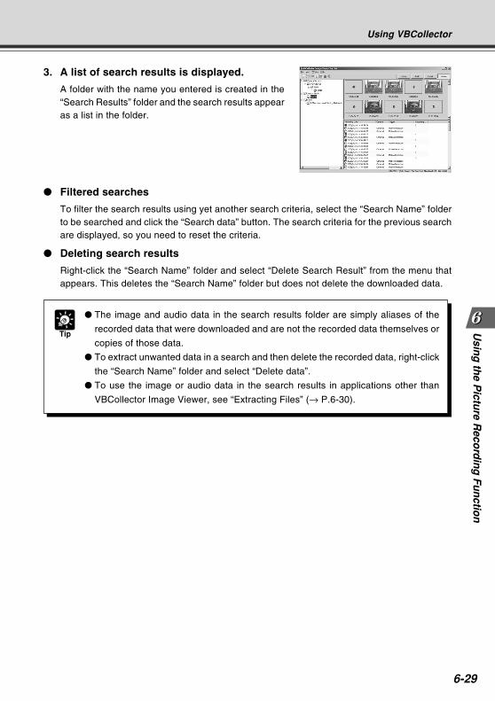
6-29
Usin
g th
e Pictu
re Reco
rdin
g F
un
ction
Using VBCollector
3. A list of search results is displayed.
A folder with the name you entered is created in the“Search Results” folder and the search results appearas a list in the folder.
Filtered searches
To filter the search results using yet another search criteria, select the “Search Name” folderto be searched and click the “Search data” button. The search criteria for the previous searchare displayed, so you need to reset the criteria.
Deleting search results
Right-click the “Search Name” folder and select “Delete Search Result” from the menu thatappears. This deletes the “Search Name” folder but does not delete the downloaded data.
Tip
The image and audio data in the search results folder are simply aliases of the
recorded data that were downloaded and are not the recorded data themselves or
copies of those data.
To extract unwanted data in a search and then delete the recorded data, right-click
the “Search Name” folder and select “Delete data”.
To use the image or audio data in the search results in applications other than
VBCollector Image Viewer, see “Extracting Files” (→ P.6-30).
COPY
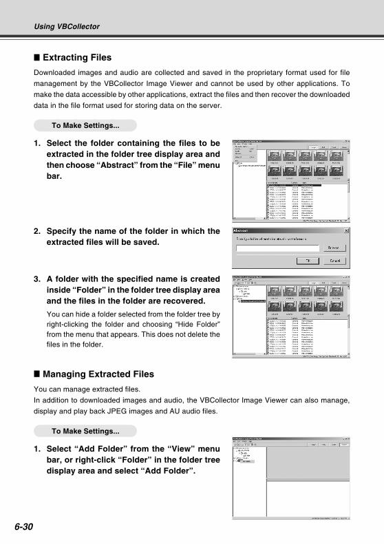
6-30
Using VBCollector
Extracting Files
Downloaded images and audio are collected and saved in the proprietary format used for file
management by the VBCollector Image Viewer and cannot be used by other applications. To
make the data accessible by other applications, extract the files and then recover the downloaded
data in the file format used for storing data on the server.
To Make Settings...
1. Select the folder containing the files to beextracted in the folder tree display area andthen choose “Abstract” from the “File” menubar.
2. Specify the name of the folder in which theextracted files will be saved.
3. A folder with the specified name is createdinside “Folder” in the folder tree display areaand the files in the folder are recovered.
You can hide a folder selected from the folder tree byright-clicking the folder and choosing “Hide Folder”from the menu that appears. This does not delete thefiles in the folder.
Managing Extracted Files
You can manage extracted files.
In addition to downloaded images and audio, the VBCollector Image Viewer can also manage,
display and play back JPEG images and AU audio files.
To Make Settings...
1. Select “Add Folder” from the “View” menubar, or right-click “Folder” in the folder treedisplay area and select “Add Folder”.
COPY
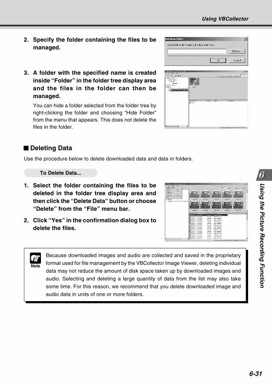
6-31
Usin
g th
e Pictu
re Reco
rdin
g F
un
ction
Using VBCollector
Note
Because downloaded images and audio are collected and saved in the proprietary
format used for file management by the VBCollector Image Viewer, deleting individual
data may not reduce the amount of disk space taken up by downloaded images and
audio. Selecting and deleting a large quantity of data from the list may also take
some time. For this reason, we recommend that you delete downloaded image and
audio data in units of one or more folders.
2. Specify the folder containing the files to bemanaged.
3. A folder with the specified name is createdinside “Folder” in the folder tree display areaand the files in the folder can then bemanaged.
You can hide a folder selected from the folder tree byright-clicking the folder and choosing “Hide Folder”from the menu that appears. This does not delete thefiles in the folder.
Deleting Data
Use the procedure below to delete downloaded data and data in folders.
To Delete Data...
1. Select the folder containing the files to bedeleted in the folder tree display area andthen click the “Delete Data” button or choose“Delete” from the “File” menu bar.
2. Click “Yes” in the confirmation dialog box todelete the files.CO
PY
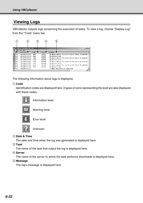
6-32
Viewing Logs
VBCollector outputs logs concerning the execution of tasks. To view a log, choose “Display Log”
from the “Tools” menu bar.
The following information about logs is displayed:
q Code
Identification codes are displayed here. 4 types of icons representing the level are also displayed
with these codes.
Information level
Warning level
Error level
Unknown
w Date & Time
The date and time when the log was generated is displayed here.
e Task
The name of the task that output the log is displayed here.
r Server
The name of the server to which the task performs downloads is displayed here.
t Message
The log’s message is displayed here.
Using VBCollector
q w e r t
COPY
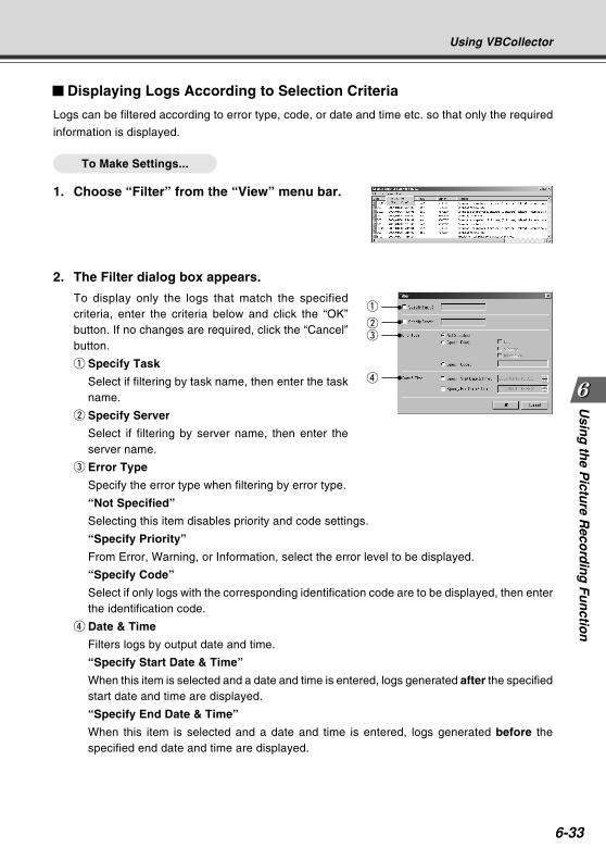
6-33
Usin
g th
e Pictu
re Reco
rdin
g F
un
ction
Displaying Logs According to Selection Criteria
Logs can be filtered according to error type, code, or date and time etc. so that only the required
information is displayed.
To Make Settings...
1. Choose “Filter” from the “View” menu bar.
2. The Filter dialog box appears.
To display only the logs that match the specifiedcriteria, enter the criteria below and click the “OK”button. If no changes are required, click the “Cancel”button.
q Specify Task
Select if filtering by task name, then enter the taskname.
w Specify Server
Select if filtering by server name, then enter theserver name.
e Error Type
Specify the error type when filtering by error type.
“Not Specified”
Selecting this item disables priority and code settings.
“Specify Priority”
From Error, Warning, or Information, select the error level to be displayed.
“Specify Code”
Select if only logs with the corresponding identification code are to be displayed, then enterthe identification code.
r Date & Time
Filters logs by output date and time.
“Specify Start Date & Time”
When this item is selected and a date and time is entered, logs generated after the specifiedstart date and time are displayed.
“Specify End Date & Time”
When this item is selected and a date and time is entered, logs generated before thespecified end date and time are displayed.
Using VBCollector
q
we
r
COPY
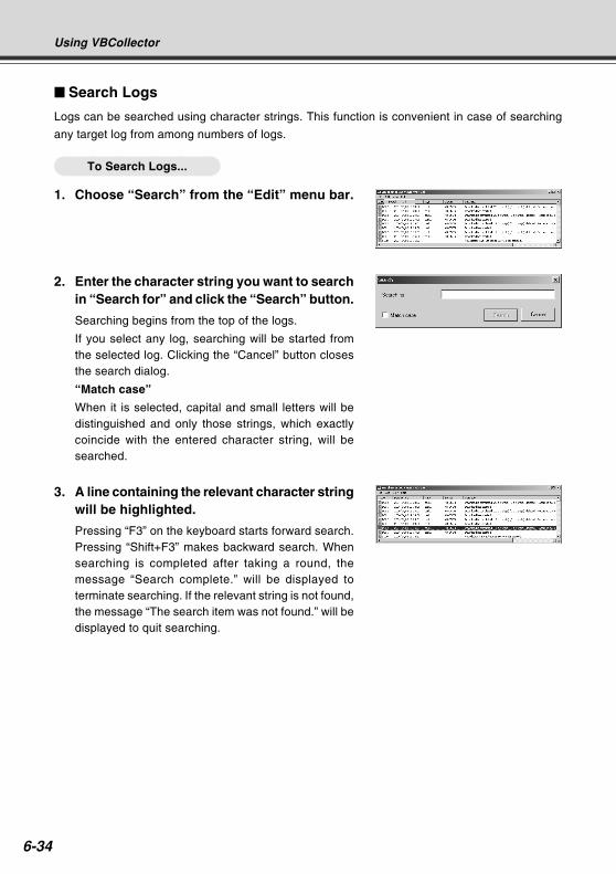
6-34
3. A line containing the relevant character stringwill be highlighted.
Pressing “F3” on the keyboard starts forward search.Pressing “Shift+F3” makes backward search. Whensearching is completed after taking a round, themessage “Search complete.” will be displayed toterminate searching. If the relevant string is not found,the message “The search item was not found.” will bedisplayed to quit searching.
Search Logs
Logs can be searched using character strings. This function is convenient in case of searching
any target log from among numbers of logs.
To Search Logs...
1. Choose “Search” from the “Edit” menu bar.
Using VBCollector
2. Enter the character string you want to searchin “Search for” and click the “Search” button.
Searching begins from the top of the logs.
If you select any log, searching will be started fromthe selected log. Clicking the “Cancel” button closesthe search dialog.
“Match case”
When it is selected, capital and small letters will bedistinguished and only those strings, which exactlycoincide with the entered character string, will besearched.
COPY
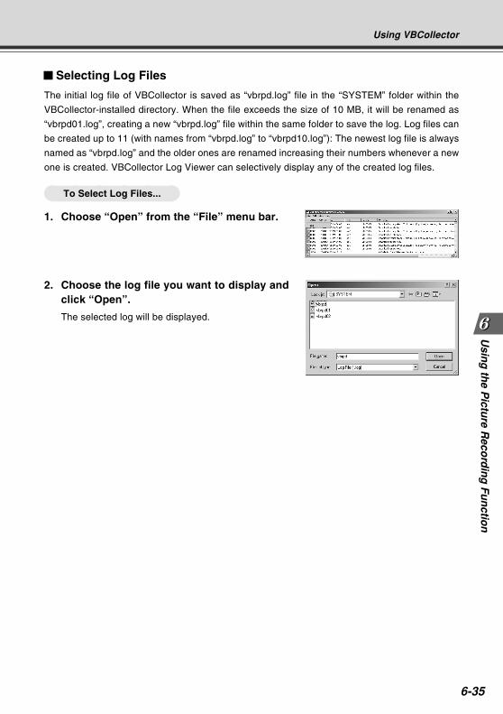
6-35
Usin
g th
e Pictu
re Reco
rdin
g F
un
ction
Selecting Log Files
The initial log file of VBCollector is saved as “vbrpd.log” file in the “SYSTEM” folder within the
VBCollector-installed directory. When the file exceeds the size of 10 MB, it will be renamed as
“vbrpd01.log”, creating a new “vbrpd.log” file within the same folder to save the log. Log files can
be created up to 11 (with names from “vbrpd.log” to “vbrpd10.log”): The newest log file is always
named as “vbrpd.log” and the older ones are renamed increasing their numbers whenever a new
one is created. VBCollector Log Viewer can selectively display any of the created log files.
To Select Log Files...
1. Choose “Open” from the “File” menu bar.
2. Choose the log file you want to display andclick “Open”.
The selected log will be displayed.
Using VBCollector
COPY
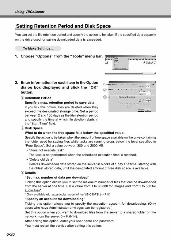
6-36
Using VBCollector
2. Enter information for each item in the Optiondialog box displayed and click the “OK”button.
q Retention PeriodSpecify a max. retention period to save data:If you tick this option, files are deleted when theyexceed the designated storage time. Set a periodbetween 2 and 100 days as the file retention periodand specify the time at which file deletion starts inthe “Start Time” field.
w Disk SpaceWhat to do when the free space falls below the specified value:Specify the action to be taken when the amount of free space available on the drive containingthe folder used for saving files while tasks are running drops below the level specified in“Free Space”. Set a value between 300 and 2000 MB.• “Does not execute task”
The task is not performed when the scheduled execution time is reached.• “Delete old data”
Deletes downloaded data stored on the server in blocks of 1 day at a time, starting withthe oldest stored data, until the designated amount of free disk space is available.
e Details“Set max. number of data per download”Ticking this option allows you to set the maximum number of files that can be downloadedfrom the server at one time. Set a value from 1 to 30,000 for images and from 1 to 500 foraudio files*.* Only available with a particular model of the VB-C50FSi (→ P.iii)
“Specify an account for downloading”Ticking this option allows you to specify the execution account for downloading. (Onlyusers who have Administrator privileges can be registered.)Set this option when you want to download files from the server to a shared folder on thenetwork from the server (→ P.6-14).After ticking this option, enter your user name and password.You must restart the service after setting this option.
Setting Retention Period and Disk Space
You can set the file retention period and specify the action to be taken if the specified data capacity
on the drive used for saving downloaded data is exceeded.
To Make Settings...
1. Choose “Options” from the “Tools” menu bar.
q
w
e
COPY
6-37
Usin
g th
e Pictu
re Reco
rdin
g F
un
ction
Using VBCollector
Note
When there is no more free space on the drive on which the files are saved, LogS023 “Execution failure: Available space on the server gets low.” or D029 “Downloadis aborted because of insufficient free space.” is output.
If you specify settings to delete old data, please consider the possibility that theimages you have downloaded the previous day may also be deleted.
COPY

6-38
COPY

Appendix
Chapter
COPY
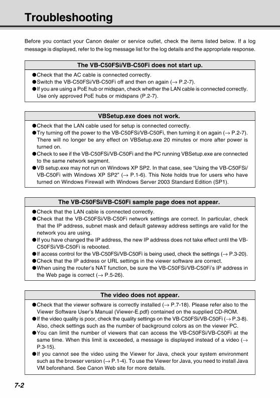
7-2
Troubleshooting
Before you contact your Canon dealer or service outlet, check the items listed below. If a log
message is displayed, refer to the log message list for the log details and the appropriate response.
The VB-C50FSi/VB-C50Fi does not start up.
Check that the AC cable is connected correctly.Switch the VB-C50FSi/VB-C50Fi off and then on again (→ P.2-7). If you are using a PoE hub or midspan, check whether the LAN cable is connected correctly.
Use only approved PoE hubs or midspans (P.2-7).
VBSetup.exe does not work.
Check that the LAN cable used for setup is connected correctly.Try turning off the power to the VB-C50FSi/VB-C50Fi, then turning it on again (→ P.2-7).
There will no longer be any effect on VBSetup.exe 20 minutes or more after power isturned on.
Check to see if the VB-C50FSi/VB-C50Fi and the PC running VBSetup.exe are connectedto the same network segment.
VB setup.exe may not run on Windows XP SP2. In that case, see “Using the VB-C50FSi/VB-C50Fi with Windows XP SP2” (→ P.1-6). This Note holds true for users who haveturned on Windows Firewall with Windows Server 2003 Standard Edition (SP1).
The VB-C50FSi/VB-C50Fi sample page does not appear.
Check that the LAN cable is connected correctly.Check that the VB-C50FSi/VB-C50Fi network settings are correct. In particular, check
that the IP address, subnet mask and default gateway address settings are valid for thenetwork you are using.
If you have changed the IP address, the new IP address does not take effect until the VB-C50FSi/VB-C50Fi is rebooted.
If access control for the VB-C50FSi/VB-C50Fi is being used, check the settings (→ P.3-20).Check that the IP address or URL settings in the viewer software are correct.When using the router’s NAT function, be sure the VB-C50FSi/VB-C50Fi’s IP address in
the Web page is correct (→ P.5-26).
The video does not appear.
Check that the viewer software is correctly installed (→ P.7-18). Please refer also to theViewer Software User’s Manual (Viewer-E.pdf) contained on the supplied CD-ROM.
If the video quality is poor, check the quality settings on the VB-C50FSi/VB-C50Fi (→ P.3-8).Also, check settings such as the number of background colors as on the viewer PC.
You can limit the number of viewers that can access the VB-C50FSi/VB-C50Fi at thesame time. When this limit is exceeded, a message is displayed instead of a video (→P.3-15).
If you cannot see the video using the Viewer for Java, check your system environmentsuch as the browser version (→ P.1-4). To use the Viewer for Java, you need to install JavaVM beforehand. See Canon Web site for more details.
COPY
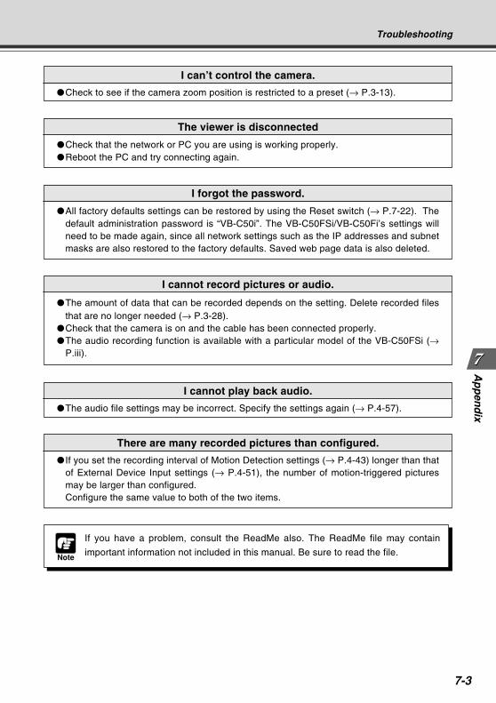
7-3
Ap
pen
dix
Troubleshooting
I forgot the password.
All factory defaults settings can be restored by using the Reset switch (→ P.7-22). Thedefault administration password is “VB-C50i”. The VB-C50FSi/VB-C50Fi’s settings willneed to be made again, since all network settings such as the IP addresses and subnetmasks are also restored to the factory defaults. Saved web page data is also deleted.
I can’t control the camera.
Check to see if the camera zoom position is restricted to a preset (→ P.3-13).
Note
If you have a problem, consult the ReadMe also. The ReadMe file may contain
important information not included in this manual. Be sure to read the file.
The viewer is disconnected
Check that the network or PC you are using is working properly.Reboot the PC and try connecting again.
I cannot record pictures or audio.
The amount of data that can be recorded depends on the setting. Delete recorded filesthat are no longer needed (→ P.3-28).
Check that the camera is on and the cable has been connected properly.The audio recording function is available with a particular model of the VB-C50FSi (→
P.iii).
I cannot play back audio.
The audio file settings may be incorrect. Specify the settings again (→ P.4-57).
There are many recorded pictures than configured.
If you set the recording interval of Motion Detection settings (→ P.4-43) longer than thatof External Device Input settings (→ P.4-51), the number of motion-triggered picturesmay be larger than configured.Configure the same value to both of the two items.
COPY
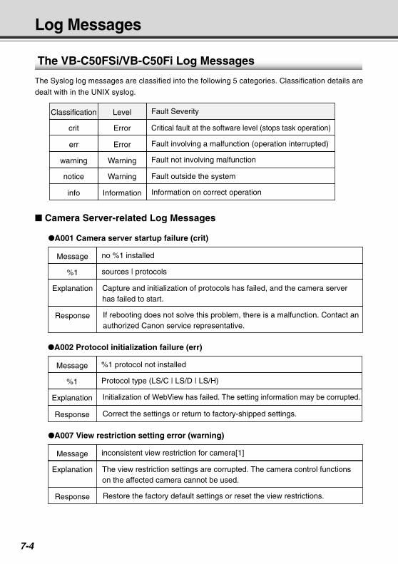
7-4
Message
Explanation
Response
A007 View restriction setting error (warning)
inconsistent view restriction for camera[1]
The view restriction settings are corrupted. The camera control functions on the affected camera cannot be used.
Restore the factory default settings or reset the view restrictions.
Log Messages
Classification
crit
err
Fault Severity
Critical fault at the software level (stops task operation)
Fault involving a malfunction (operation interrupted)
Level
Error
Error
warning
notice
info
Fault not involving malfunction
Fault outside the system
Information on correct operation
Warning
Warning
Information
Message
Explanation
A001 Camera server startup failure (crit)
no %1 installed
Capture and initialization of protocols has failed, and the camera server has failed to start.
%1 sources | protocols
Response If rebooting does not solve this problem, there is a malfunction. Contact an authorized Canon service representative.
Message
A002 Protocol initialization failure (err)
%1 protocol not installed
%1 Protocol type (LS/C | LS/D | LS/H)
Explanation Initialization of WebView has failed. The setting information may be corrupted.
Response Correct the settings or return to factory-shipped settings.
Camera Server-related Log Messages
The VB-C50FSi/VB-C50Fi Log Messages
The Syslog log messages are classified into the following 5 categories. Classification details are
dealt with in the UNIX syslog.
COPY
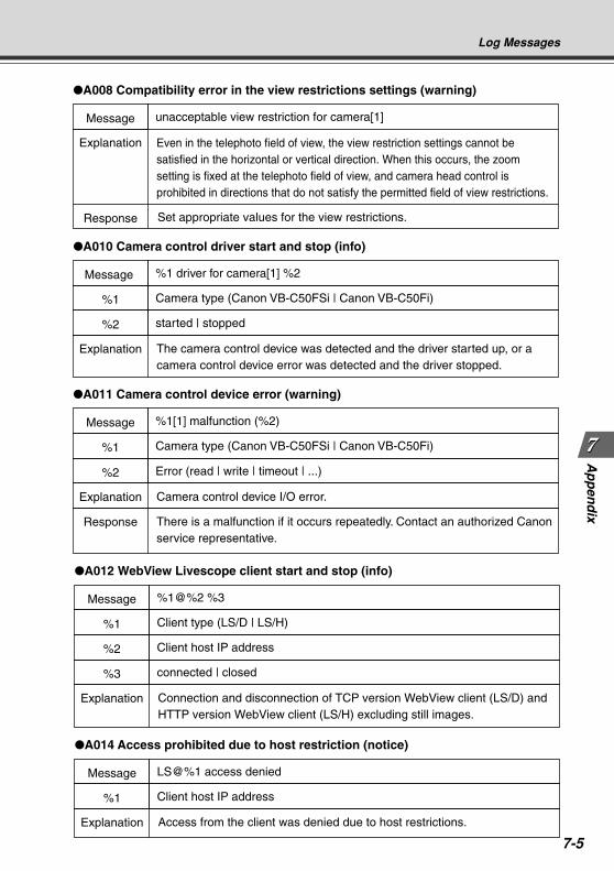
7-5
Ap
pen
dix
Log Messages
Message
Explanation
Response
A008 Compatibility error in the view restrictions settings (warning)
unacceptable view restriction for camera[1]
Set appropriate values for the view restrictions.
Even in the telephoto field of view, the view restriction settings cannot be satisfied in the horizontal or vertical direction. When this occurs, the zoom setting is fixed at the telephoto field of view, and camera head control is prohibited in directions that do not satisfy the permitted field of view restrictions.
Message
Explanation
A010 Camera control driver start and stop (info)
%1 driver for camera[1] %2
The camera control device was detected and the driver started up, or a camera control device error was detected and the driver stopped.
%1 Camera type (Canon VB-C50FSi | Canon VB-C50Fi)
%2 started | stopped
Message
Explanation
A011 Camera control device error (warning)
%1[1] malfunction (%2)
Camera control device I/O error.
%1 Camera type (Canon VB-C50FSi | Canon VB-C50Fi)
%2 Error (read | write | timeout | ...)
Response There is a malfunction if it occurs repeatedly. Contact an authorized Canonservice representative.
Message
Explanation
A012 WebView Livescope client start and stop (info)
%1@%2 %3
Connection and disconnection of TCP version WebView client (LS/D) and HTTP version WebView client (LS/H) excluding still images.
%1 Client type (LS/D | LS/H)
%2 Client host IP address
%3 connected | closed
Message
Explanation
A014 Access prohibited due to host restriction (notice)
LS@%1 access denied
Access from the client was denied due to host restrictions.
%1 Client host IP address
COPY
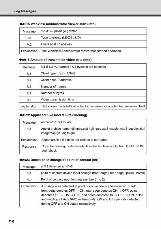
7-6
Message
Explanation
A023 Detection in change of point of contact (err)
a %1 detected at In%2
%1 point of contact device input change (front-edge | rear-edge | pulse | notch)
%2 Point of contact input terminal number (1 to 2)
A change was detected at point of contact device terminal In1 or In2. front-edge denotes OFF → ON, rear-edge denotes ON → OFF, pulse denotes OFF → ON → OFF, and notch denotes ON → OFF → ON. pulse and notch are brief (10-20 milliseconds) ON and OFF periods detected during OFF and ON states respectively.
Message
Explanation
Response
A022 Applet archive load failure (warning)
archive/%1 not found
Applet archive file does not exist or is corrupted.
Copy the missing (or damaged) file in the '/archive' applet from the CD-ROM and reboot.
%1 Applet archive name (glimpse.cab | glimpse.zip | lvapplet.cab | lvapplet.zip | imagemap.gif | digits.gif)
Log Messages
Message
Explanation
A015 WebView Administrator Viewer start (info)
%1@%2 privilege granted
The WebView Administrator Viewer has started operation.
%1 Type of clients (LS/C | LS/D)
%2 Client host IP address
Message
%3
A016 Amount of transmitted video data (info)
%1@%2 %3 frames / %4 bytes in %5 seconds
Number of frames
%1 Client type (LS/D | LS/H)
%2 Client host IP address
Explanation This shows the results of video transmission for a video transmission client.
%4 Number of bytes
%5 Video transmission time
COPY
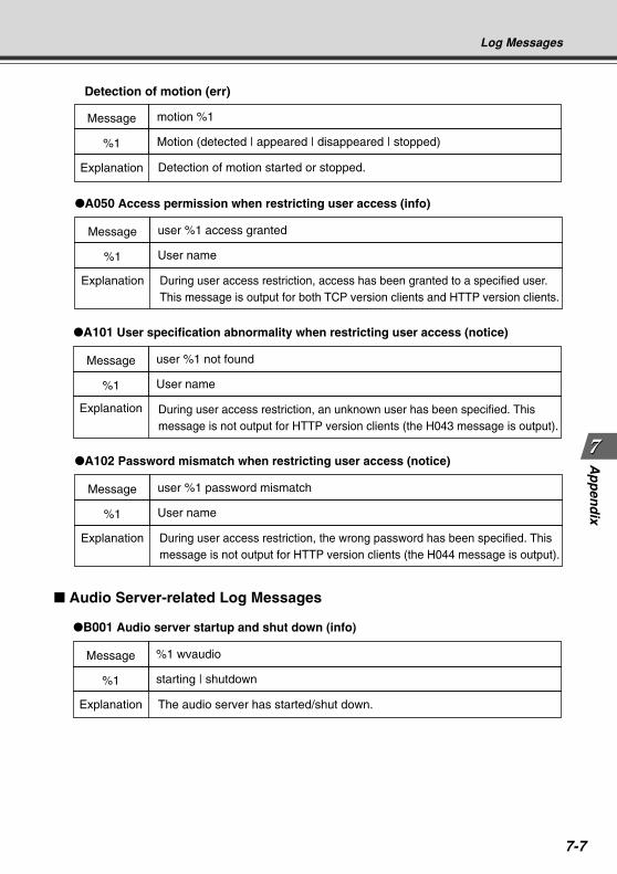
7-7
Ap
pen
dix
Log Messages
Message
A050 Access permission when restricting user access (info)
user %1 access granted
Explanation During user access restriction, access has been granted to a specified user. This message is output for both TCP version clients and HTTP version clients.
%1 User name
Message
A101 User specification abnormality when restricting user access (notice)
user %1 not found
Explanation During user access restriction, an unknown user has been specified. This message is not output for HTTP version clients (the H043 message is output).
%1 User name
Message
A102 Password mismatch when restricting user access (notice)
user %1 password mismatch
Explanation During user access restriction, the wrong password has been specified. This message is not output for HTTP version clients (the H044 message is output).
%1 User name
Message
Explanation
Detection of motion (err)
motion %1
Detection of motion started or stopped.
%1 Motion (detected | appeared | disappeared | stopped)
Audio Server-related Log Messages
Message
B001 Audio server startup and shut down (info)
%1 wvaudio
Explanation The audio server has started/shut down.
%1 starting | shutdown
COPY
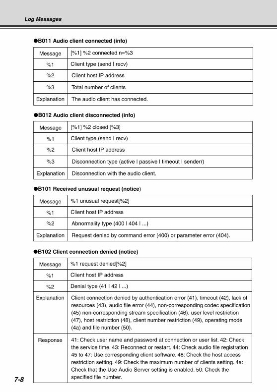
7-8
Log Messages
Message
B102 Client connection denied (notice)
%1 request denied[%2]
%1 Client host IP address
%2 Denial type (41 | 42 | ...)
Explanation
Response
Client connection denied by authentication error (41), timeout (42), lack of resources (43), audio file error (44), non-corresponding codec specification (45) non-corresponding stream specification (46), user level restriction (47), host restriction (48), client number restriction (49), operating mode (4a) and file number (50).
41: Check user name and password at connection or user list. 42: Check the service time. 43: Reconnect or restart. 44: Check audio file registration 45 to 47: Use corresponding client software. 48: Check the host access restriction setting. 49: Check the maximum number of clients setting. 4a: Check that the Use Audio Server setting is enabled. 50: Check the specified file number.
Message
B012 Audio client disconnected (info)
[%1] %2 closed [%3]
%2 Client host IP address
%3 Disconnection type (active | passive | timeout | senderr)
Explanation Disconnection with the audio client.
%1 Client type (send | recv)
Message
B101 Received unusual request (notice)
%1 unusual request[%2]
%2 Abnormality type (400 | 404 | ...)
Explanation Request denied by command error (400) or parameter error (404).
%1 Client host IP address
Message
B011 Audio client connected (info)
[%1] %2 connected n=%3
%2 Client host IP address
%3 Total number of clients
Explanation The audio client has connected.
%1 Client type (send | recv)
COPY
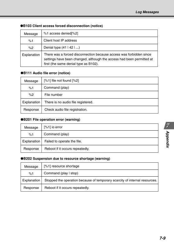
7-9
Ap
pen
dix
Log Messages
Message
B103 Client access forced disconnection (notice)
%1 access denied[%2]
Explanation
%1 Client host IP address
%2 Denial type (41 | 42 | ...)
There was a forced disconnection because access was forbidden since settings have been changed, although the access had been permitted at first (the same denial type as B102).
Message
B111 Audio file error (notice)
[%1] file not found [%2]
%2 File number
Explanation There is no audio file registered.
Response Check audio file registration.
%1 Command (play)
Message
B201 File operation error (warning)
[%1] io error
Explanation Failed to operate the file.
Response Reboot if it occurs repeatedly.
%1 Command (play)
Message
B202 Suspension due to resource shortage (warning)
[%1] resource shortage
Explanation Stopped the operation because of temporary scarcity of internal resources.
Response Reboot if it occurs repeatedly.
%1 Command (play | stop)
COPY
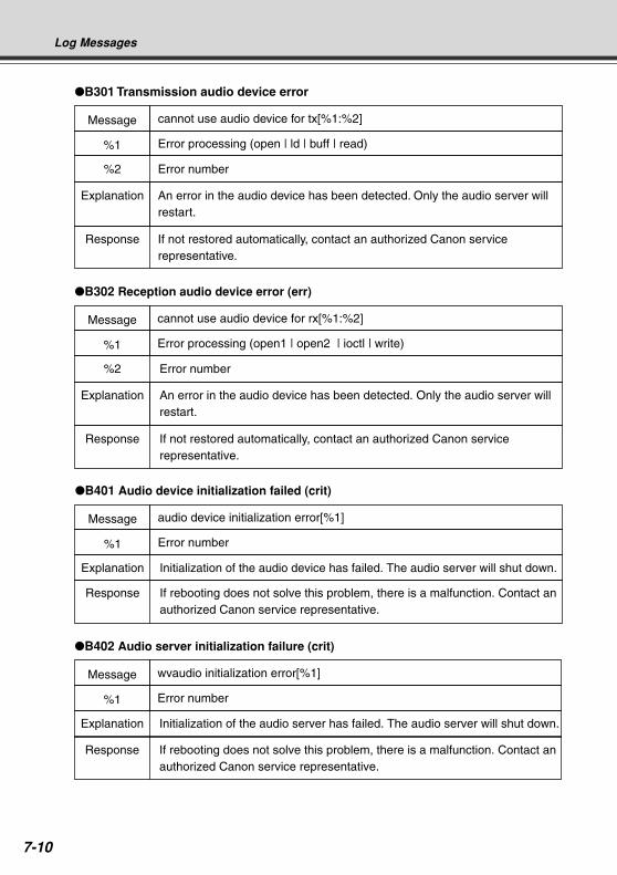
7-10
Log Messages
Message
B401 Audio device initialization failed (crit)
audio device initialization error[%1]
%1 Error number
Response If rebooting does not solve this problem, there is a malfunction. Contact an authorized Canon service representative.
Explanation Initialization of the audio device has failed. The audio server will shut down.
Message
B302 Reception audio device error (err)
cannot use audio device for rx[%1:%2]
%2 Error number
Explanation
Response
An error in the audio device has been detected. Only the audio server will restart.
If not restored automatically, contact an authorized Canon service representative.
%1 Error processing (open1 | open2 | ioctl | write)
Message
B402 Audio server initialization failure (crit)
wvaudio initialization error[%1]
%1 Error number
Response If rebooting does not solve this problem, there is a malfunction. Contact an authorized Canon service representative.
Explanation Initialization of the audio server has failed. The audio server will shut down.
Message
B301 Transmission audio device error
cannot use audio device for tx[%1:%2]
%2 Error number
Explanation
Response
An error in the audio device has been detected. Only the audio server will restart.
If not restored automatically, contact an authorized Canon service representative.
%1 Error processing (open | ld | buff | read)
COPY
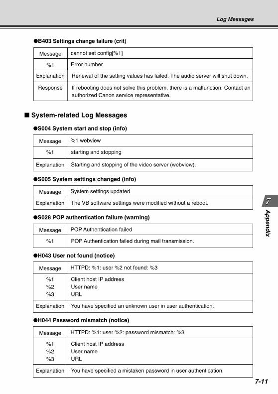
7-11
Ap
pen
dix
Message
Explanation
S005 System settings changed (info)
System settings updated
The VB software settings were modified without a reboot.
Message
%1%2%3
H043 User not found (notice)
HTTPD: %1: user %2 not found: %3
Client host IP addressUser nameURL
Explanation You have specified an unknown user in user authentication.
Message
%1
S004 System start and stop (info)
%1 webview
starting and stopping
Explanation Starting and stopping of the video server (webview).
Message
%1
S028 POP authentication failure (warning)
POP Authentication failed
POP Authentication failed during mail transmission.
Message
%1%2%3
H044 Password mismatch (notice)
HTTPD: %1: user %2: password mismatch: %3
Client host IP addressUser nameURL
Explanation You have specified a mistaken password in user authentication.
System-related Log Messages
Log Messages
Message
B403 Settings change failure (crit)
cannot set config[%1]
%1 Error number
Response If rebooting does not solve this problem, there is a malfunction. Contact an authorized Canon service representative.
Explanation Renewal of the setting values has failed. The audio server will shut down.
COPY
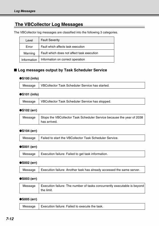
7-12
Fault Severity
Fault which affects task execution
Fault which does not affect task execution
Level
Error
Warning
Information on correct operationInformation
The VBCollector Log Messages
The VBCollector log messages are classified into the following 3 categories.
Log Messages
Log messages output by Task Scheduler Service
S100 (info)
Message VBCollector Task Scheduler Service has started.
S101 (info)
Message VBCollector Task Scheduler Service has stopped.
S102 (err)
Message Stops the VBCollector Task Scheduler Service because the year of 2038has arrived.
S104 (err)
Message Failed to start the VBCollector Task Scheduler Service.
S001 (err)
Message Execution failure: Failed to get task information.
S002 (err)
Message Execution failure: Another task has already accessed the same server.
S003 (err)
Message Execution failure: The number of tasks concurrently executable is beyondthe limit.
S005 (err)
Message Execution failure: Failed to execute the task.
COPY
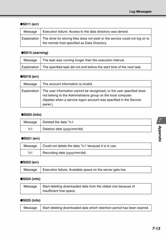
7-13
Ap
pen
dix
Log Messages
S011 (err)
Message Execution failure: Access to the data directory was denied.
Explanation The drive for storing files does not exist or the service could not log on tothe remote host specified as Data Directory.
S015 (warning)
Message The task was running longer than the execution interval.
Explanation The specified task did not end before the start time of the next task.
S019 (err)
Message The account information is invalid.
Explanation The user information cannot be recognized, or the user specified doesnot belong to the Administrators group on the local computer.(Applies when a service logon account was specified in the Servicepanel.)
S020 (info)
Message Deleted the data '%1.
%1 Deletion date (yyyy/mm/dd)
S021 (err)
Message Could not delete the data '%1' because it is in use.
%1 Recording date (yyyy/mm/dd)
S023 (err)
Message Execution failure: Available space on the server gets low.
S024 (info)
Message Start deleting downloaded data from the oldest one because ofinsufficient free space.
S025 (info)
Message Start deleting downloaded data which retention period has been expired.
COPY
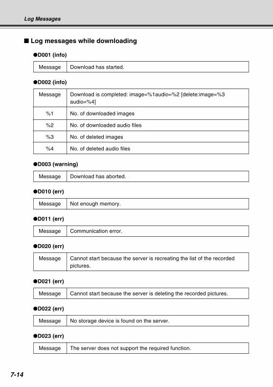
7-14
Log Messages
D001 (info)
Message Download has started.
D002 (info)
Message Download is completed: image=%1audio=%2 [delete:image=%3audio=%4]
%1 No. of downloaded images
%2 No. of downloaded audio files
%3 No. of deleted images
%4 No. of deleted audio files
D003 (warning)
Message Download has aborted.
D010 (err)
Message Not enough memory.
D011 (err)
Message Communication error.
D020 (err)
Message Cannot start because the server is recreating the list of the recordedpictures.
D021 (err)
Message Cannot start because the server is deleting the recorded pictures.
D022 (err)
Message No storage device is found on the server.
D023 (err)
Message The server does not support the required function.
Log messages while downloading
COPY
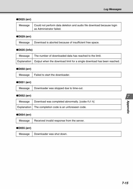
7-15
Ap
pen
dix
Log Messages
D025 (err)
Message Could not perform data deletion and audio file download because loginas Administrator failed.
D029 (err)
Message Download is aborted because of insufficient free space.
D035 (info)
Message The number of downloaded data has reached to the limit.
Explanation Output when the download limit for a single download has been reached.
D050 (err)
Message Failed to start the downloader.
D051 (err)
Message Downloader was stopped due to time-out.
D052 (err)
Message Download was completed abnormally. [code=%1 h]
Explanation The completion code is an unforeseen code.
D054 (err)
Message Received invalid response from the server.
D055 (err)
Message Downloader was shut down.
COPY
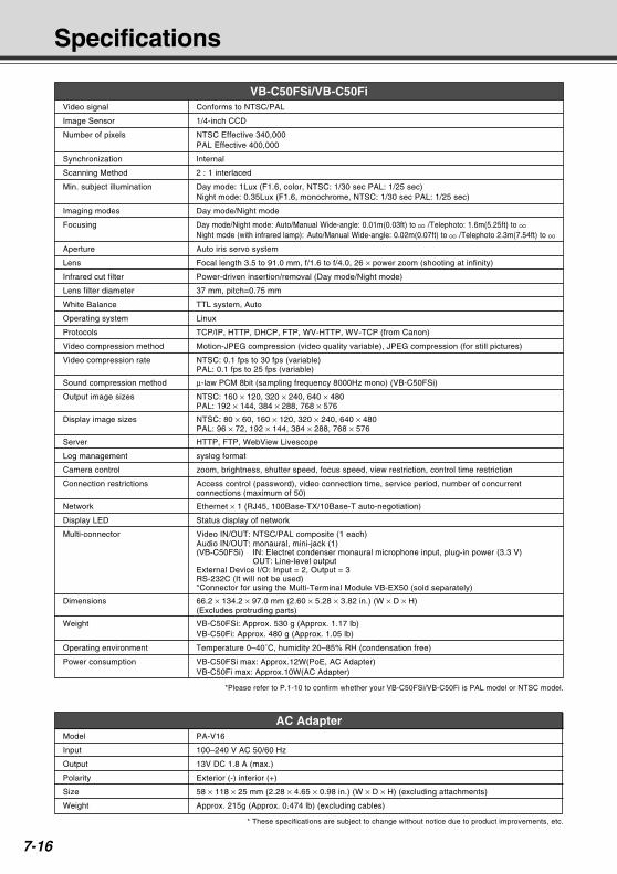
7-16
VB-C50FSi/VB-C50FiVideo signal Conforms to NTSC/PAL
Image Sensor 1/4-inch CCD
Number of pixels NTSC Effective 340,000PAL Effective 400,000
Synchronization Internal
Scanning Method 2 : 1 interlaced
Min. subject illumination Day mode: 1Lux (F1.6, color, NTSC: 1/30 sec PAL: 1/25 sec)Night mode: 0.35Lux (F1.6, monochrome, NTSC: 1/30 sec PAL: 1/25 sec)
Imaging modes Day mode/Night mode
Focusing Day mode/Night mode: Auto/Manual Wide-angle: 0.01m(0.03ft) to /Telephoto: 1.6m(5.25ft) to Night mode (with infrared lamp): Auto/Manual Wide-angle: 0.02m(0.07ft) to /Telephoto 2.3m(7.54ft) to
Aperture Auto iris servo system
Lens Focal length 3.5 to 91.0 mm, f/1.6 to f/4.0, 26 × power zoom (shooting at infinity)
Infrared cut filter Power-driven insertion/removal (Day mode/Night mode)
Lens filter diameter 37 mm, pitch=0.75 mm
White Balance TTL system, Auto
Operating system Linux
Protocols TCP/IP, HTTP, DHCP, FTP, WV-HTTP, WV-TCP (from Canon)
Video compression method Motion-JPEG compression (video quality variable), JPEG compression (for still pictures)
Video compression rate NTSC: 0.1 fps to 30 fps (variable)PAL: 0.1 fps to 25 fps (variable)
Sound compression method µ-law PCM 8bit (sampling frequency 8000Hz mono) (VB-C50FSi)
Output image sizes NTSC: 160 × 120, 320 × 240, 640 × 480PAL: 192 × 144, 384 × 288, 768 × 576
Display image sizes NTSC: 80 × 60, 160 × 120, 320 × 240, 640 × 480PAL: 96 × 72, 192 × 144, 384 × 288, 768 × 576
Server HTTP, FTP, WebView Livescope
Log management syslog format
Camera control zoom, brightness, shutter speed, focus speed, view restriction, control time restriction
Connection restrictions Access control (password), video connection time, service period, number of concurrentconnections (maximum of 50)
Network Ethernet × 1 (RJ45, 100Base-TX/10Base-T auto-negotiation)
Display LED Status display of network
Multi-connector Video IN/OUT: NTSC/PAL composite (1 each)Audio IN/OUT: monaural, mini-jack (1)(VB-C50FSi) IN: Electret condenser monaural microphone input, plug-in power (3.3 V)
OUT: Line-level outputExternal Device I/O: Input = 2, Output = 3RS-232C (It will not be used)*Connector for using the Multi-Terminal Module VB-EX50 (sold separately)
Dimensions 66.2 × 134.2 × 97.0 mm (2.60 × 5.28 × 3.82 in.) (W × D × H)(Excludes protruding parts)
Weight VB-C50FSi: Approx. 530 g (Approx. 1.17 lb)VB-C50Fi: Approx. 480 g (Approx. 1.05 lb)
Operating environment Temperature 0–40˚C, humidity 20–85% RH (condensation free)
Power consumption VB-C50FSi max: Approx.12W(PoE, AC Adapter)VB-C50Fi max: Approx.10W(AC Adapter)
*Please refer to P.1-10 to confirm whether your VB-C50FSi/VB-C50Fi is PAL model or NTSC model.
AC AdapterModel PA-V16
Input 100–240 V AC 50/60 Hz
Output 13V DC 1.8 A (max.)
Polarity Exterior (-) interior (+)
Size 58 × 118 × 25 mm (2.28 × 4.65 × 0.98 in.) (W × D × H) (excluding attachments)
Weight Approx. 215g (Approx. 0.474 lb) (excluding cables)
* These specifications are subject to change without notice due to product improvements, etc.
Specifications
COPY
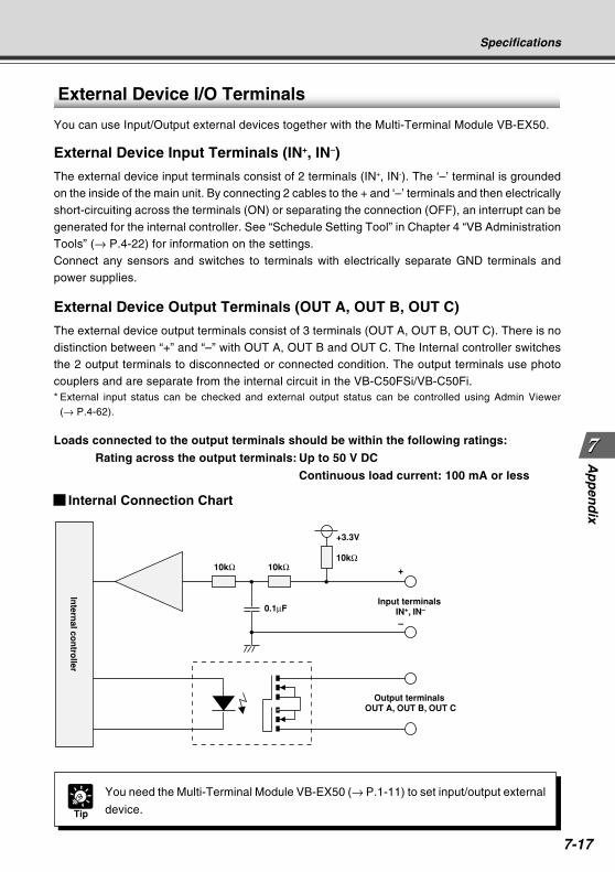
7-17
Ap
pen
dix
Specifications
+3.3V
0.1µF
10kΩ 10kΩ10kΩ
Intern
al con
troller
Input terminals IN+, IN–
Output terminals OUT A, OUT B, OUT C
+
–
External Device I/O Terminals
You can use Input/Output external devices together with the Multi-Terminal Module VB-EX50.
External Device Input Terminals (IN+, IN–)
The external device input terminals consist of 2 terminals (IN+, IN-). The ‘–’ terminal is groundedon the inside of the main unit. By connecting 2 cables to the + and ‘–’ terminals and then electricallyshort-circuiting across the terminals (ON) or separating the connection (OFF), an interrupt can begenerated for the internal controller. See “Schedule Setting Tool” in Chapter 4 “VB AdministrationTools” (→ P.4-22) for information on the settings.Connect any sensors and switches to terminals with electrically separate GND terminals andpower supplies.
External Device Output Terminals (OUT A, OUT B, OUT C)
The external device output terminals consist of 3 terminals (OUT A, OUT B, OUT C). There is nodistinction between “+” and “–” with OUT A, OUT B and OUT C. The Internal controller switchesthe 2 output terminals to disconnected or connected condition. The output terminals use photocouplers and are separate from the internal circuit in the VB-C50FSi/VB-C50Fi.* External input status can be checked and external output status can be controlled using Admin Viewer
(→ P.4-62).
Loads connected to the output terminals should be within the following ratings:
Rating across the output terminals: Up to 50 V DC
Continuous load current: 100 mA or less
Internal Connection Chart
Tip
You need the Multi-Terminal Module VB-EX50 (→ P.1-11) to set input/output external
device.
COPY
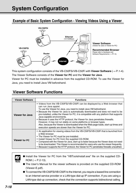
7-18
Note
Install the Viewer for PC from the “VBToolsInstall.exe” file on the supplied CD-
ROM (→ P.2-13).
The User’s Manual for the viewer software is provided on the supplied CD-ROM
(Viewer-E.pdf).
To connect the VB-C50FSi/VB-C50Fi to the Internet, you require a leased line connection
to an Internet service provider or a LAN-type dial-up IP connection. If you are using a
LAN-type dial-up connection, check that the connection supports bidirectional calling.
System Configuration
This system configuration consists of the VB-C50FSi/VB-C50Fi with Viewer Software (→ P.1-4).
The Viewer Software consists of the Viewer for PC and the Viewer for Java.
Viewer for PC must be installed in advance from the supplied CD-ROM. To use the Viewer for
Java, you need to install Java VM beforehand.
Viewer Software Functions
Viewer for Java
• Videos from the VB-C50FSi/VB-C50Fi can be displayed by a Web browser thatcan run Java applet.To use the Viewer for Java, you need to install Java VM beforehand.
• Because the Viewer for Java is automatically downloaded and does not need to bepre-installed, unlike the Viewer for PC, it is compatible with any platform that supportsJava-capable environments.
• Because it uses the HTTP protocol, the Viewer for Java penetrates firewalls.However, it may not run stably on some platforms or browser types.Also, because the Viewer is downloaded when the Web page loads, start-up times andexecution speeds are slower than the Viewer for PC.
Viewer for PC
• An application for viewing videos from the VB-C50FSi/VB-C50Fi that is launched froma Web browser.
• The Viewer for PC must be pre-installed.• Install Viewer for PC from the supplied CD-ROM.• Compared with the Viewer for Java, start-up is faster because the Viewer does not need
to be downloaded. This Viewer is recommended for users who use the viewer frequently.• Because it supports the HTTP protocol, the Viewer for PC penetrates firewalls unscathed.
Viewer Software(Viewer for Java or Viewer for PC)
Recommended Browser Please refer to Hardware and Software Requirements (→ P.1-4).Router
VB-C50FSi
VB-C50FSi
Internet
Ethernet(10/100Mbps)
Example of Basic System Configuration - Viewing Videos Using a Viewer
Viewer Software Functions
COPY
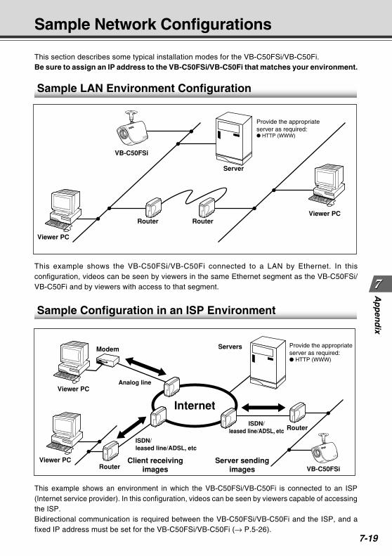
7-19
Ap
pen
dix
Sample Network Configurations
This section describes some typical installation modes for the VB-C50FSi/VB-C50Fi.Be sure to assign an IP address to the VB-C50FSi/VB-C50Fi that matches your environment.
This example shows the VB-C50FSi/VB-C50Fi connected to a LAN by Ethernet. In thisconfiguration, videos can be seen by viewers in the same Ethernet segment as the VB-C50FSi/VB-C50Fi and by viewers with access to that segment.
Sample Configuration in an ISP Environment
This example shows an environment in which the VB-C50FSi/VB-C50Fi is connected to an ISP(Internet service provider). In this configuration, videos can be seen by viewers capable of accessingthe ISP.Bidirectional communication is required between the VB-C50FSi/VB-C50Fi and the ISP, and afixed IP address must be set for the VB-C50FSi/VB-C50Fi (→ P.5-26).
Sample LAN Environment Configuration
Router Router
VB-C50FSi
Viewer PC
Viewer PC
Server
Provide the appropriate server as required: HTTP (WWW)
Internet
Router
Modem
Router
Client receivingimages
Server sendingimages VB-C50FSi
Viewer PC
Viewer PC
Servers Provide the appropriate server as required: HTTP (WWW)
ISDN/leased line/ADSL, etc
Analog line
ISDN/leased line/ADSL, etc
COPY
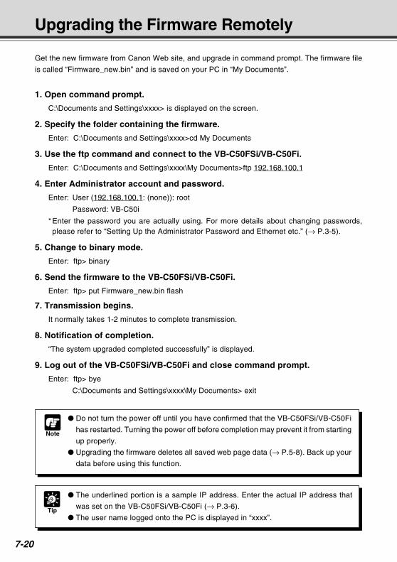
7-20
Upgrading the Firmware Remotely
Note
Do not turn the power off until you have confirmed that the VB-C50FSi/VB-C50Fi
has restarted. Turning the power off before completion may prevent it from starting
up properly.
Upgrading the firmware deletes all saved web page data (→ P.5-8). Back up your
data before using this function.
Get the new firmware from Canon Web site, and upgrade in command prompt. The firmware file
is called “Firmware_new.bin” and is saved on your PC in “My Documents”.
1. Open command prompt.
C:\Documents and Settings\xxxx> is displayed on the screen.
2. Specify the folder containing the firmware.
Enter: C:\Documents and Settings\xxxx>cd My Documents
3. Use the ftp command and connect to the VB-C50FSi/VB-C50Fi.
Enter: C:\Documents and Settings\xxxx\My Documents>ftp 192.168.100.1
4. Enter Administrator account and password.
Enter: User (192.168.100.1: (none)): root
Password: VB-C50i
* Enter the password you are actually using. For more details about changing passwords,please refer to “Setting Up the Administrator Password and Ethernet etc.” (→ P.3-5).
5. Change to binary mode.
Enter: ftp> binary
6. Send the firmware to the VB-C50FSi/VB-C50Fi.
Enter: ftp> put Firmware_new.bin flash
7. Transmission begins.
It normally takes 1-2 minutes to complete transmission.
8. Notification of completion.
“The system upgraded completed successfully” is displayed.
9. Log out of the VB-C50FSi/VB-C50Fi and close command prompt.
Enter: ftp> bye
C:\Documents and Settings\xxxx\My Documents> exit
Tip
The underlined portion is a sample IP address. Enter the actual IP address that
was set on the VB-C50FSi/VB-C50Fi (→ P.3-6).
The user name logged onto the PC is displayed in “xxxx”.
COPY
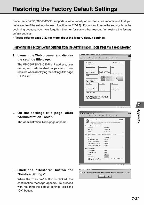
7-21
Ap
pen
dix
Restoring the Factory Default Settings
Since the VB-C50FSi/VB-C50Fi supports a wide variety of functions, we recommend that you
make a note of the settings for each function (→ P.7-23). If you want to redo the settings from the
beginning because you have forgotten them or for some other reason, first restore the factory
default settings.
* Please refer to page 7-23 for more about the factory default settings.
Restoring the Factory Default Settings from the Administration Tools Page via a Web Browser
1. Launch the Web browser and displaythe settings title page.
The VB-C50FSi/VB-C50Fi’s IP address, username, and administration password arerequired when displaying the settings title page(→ P.3-3).
2. On the settings title page, click“Administration Tools”.
The Administration Tools page appears.
3. Click the “Restore” button for“Restore Settings”.
When the “Restore” button is clicked, theconfirmation message appears. To proceedwith restoring the default settings, click the“OK” button.
COPY
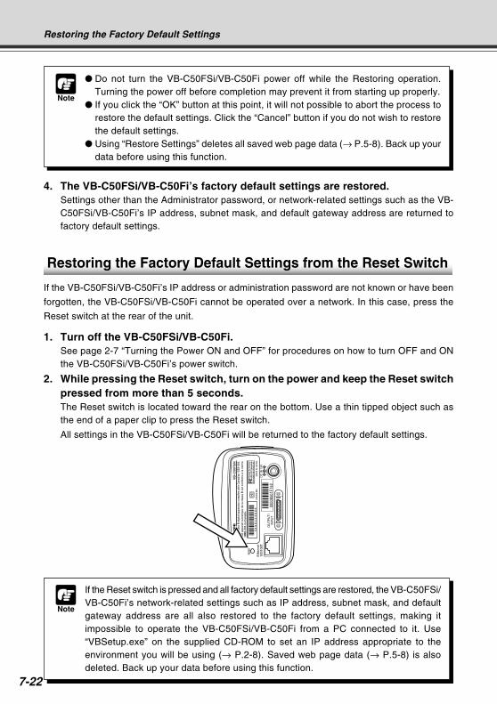
7-22
Restoring the Factory Default Settings
Note
Do not turn the VB-C50FSi/VB-C50Fi power off while the Restoring operation.Turning the power off before completion may prevent it from starting up properly.
If you click the “OK” button at this point, it will not possible to abort the process torestore the default settings. Click the “Cancel” button if you do not wish to restorethe default settings.
Using “Restore Settings” deletes all saved web page data (→ P.5-8). Back up yourdata before using this function.
4. The VB-C50FSi/VB-C50Fi’s factory default settings are restored.Settings other than the Administrator password, or network-related settings such as the VB-C50FSi/VB-C50Fi’s IP address, subnet mask, and default gateway address are returned tofactory default settings.
Note
If the Reset switch is pressed and all factory default settings are restored, the VB-C50FSi/VB-C50Fi’s network-related settings such as IP address, subnet mask, and defaultgateway address are all also restored to the factory default settings, making itimpossible to operate the VB-C50FSi/VB-C50Fi from a PC connected to it. Use“VBSetup.exe” on the supplied CD-ROM to set an IP address appropriate to theenvironment you will be using (→ P.2-8). Saved web page data (→ P.5-8) is alsodeleted. Back up your data before using this function.
Restoring the Factory Default Settings from the Reset Switch
If the VB-C50FSi/VB-C50Fi’s IP address or administration password are not known or have been
forgotten, the VB-C50FSi/VB-C50Fi cannot be operated over a network. In this case, press the
Reset switch at the rear of the unit.
1. Turn off the VB-C50FSi/VB-C50Fi.See page 2-7 “Turning the Power ON and OFF” for procedures on how to turn OFF and ONthe VB-C50FSi/VB-C50Fi’s power switch.
2. While pressing the Reset switch, turn on the power and keep the Reset switchpressed from more than 5 seconds.The Reset switch is located toward the rear on the bottom. Use a thin tipped object such asthe end of a paper clip to press the Reset switch.
All settings in the VB-C50FSi/VB-C50Fi will be returned to the factory default settings.COPY
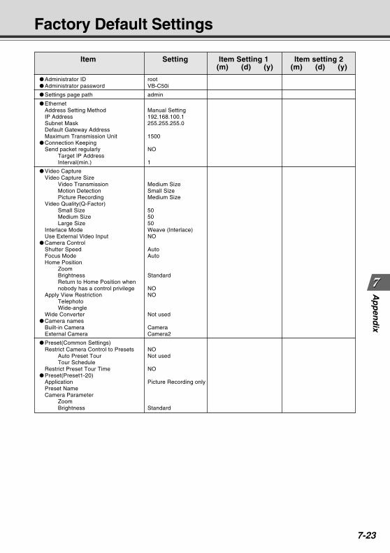
7-23
Ap
pen
dix
Factory Default Settings
Item Setting Item Setting 1 Item setting 2 (m) (d) (y) (m) (d) (y)
Administrator ID root Administrator password VB-C50i
Settings page path admin
EthernetAddress Setting Method Manual SettingIP Address 192.168.100.1Subnet Mask 255.255.255.0Default Gateway AddressMaximum Transmission Unit 1500
Connection KeepingSend packet regularly NO
Target IP AddressInterval(min.) 1
Video CaptureVideo Capture Size
Video Transmission Medium SizeMotion Detection Small SizePicture Recording Medium Size
Video Quality(Q-Factor)Small Size 50Medium Size 50Large Size 50
Interlace Mode Weave (Interlace)Use External Video Input NO
Camera ControlShutter Speed AutoFocus Mode AutoHome Position
ZoomBrightness StandardReturn to Home Position whennobody has a control privilege NO
Apply View Restriction NOTelephotoWide-angle
Wide Converter Not used Camera names
Built-in Camera CameraExternal Camera Camera2
Preset(Common Settings)Restrict Camera Control to Presets NO
Auto Preset Tour Not usedTour Schedule
Restrict Preset Tour Time NO Preset(Preset1-20)
Application Picture Recording onlyPreset NameCamera Parameter
ZoomBrightness Standard
COPY
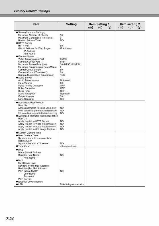
7-24
Factory Default Settings
Item Setting Item Setting 1 Item setting 2 (m) (d) (y) (m) (d) (y)
Server(Common Settings)Maximum Number of Clients 50Maximum Connection Time (sec.) 0Restrict Service Time NO
HTTP ServerHTTP Port 80Global Address for Web Pages IP Address
IP AddressPort Name
Camera ServerVideo Transmission Port 65310Camera Control Port 65311Maximum Frame Rate (fps) 30 (NTSC)/25 (PAL)Maximum Transmission Rate (Mbps) 0Control Queue Length 50Camera Control Time (sec.) 20Camera Stabilization Time (msec.) 1500
Audio ServerAudio Transmission Not usedInput Volume 50Voice Activity Detection OFFNoise Canceller OFFSlope Filter OFFAudio Reception Not usedOutput Volume 50Echo Canceller OFF
Authorized User AccountUser ListAccess permitted to listed users only NOAudio Transmission permitted to listed users only NOStill image Capture permitted to listed users only NO
Authorized/Restricted Host SpecificationHost ListApply this list to HTTP Server NOApply this list to Video Transmission NOApply this list to Audio Transmission NOApply this list to Still Image Capture NO
Current Camera Time New Camera Time
Synchronize with computer timeSet manuallySynchronize with NTP server NO
Time Zone +9 (Japan time)
DNSName Server AddressRegister Host Name NO
Host Name Mail
Mail Server HostSender’s(From) Mail AddressRecipient(To) Mail AddressPOP before SMTP NO
User NamePassword
POP Server External Device Names LED Blinks during communication
COPY
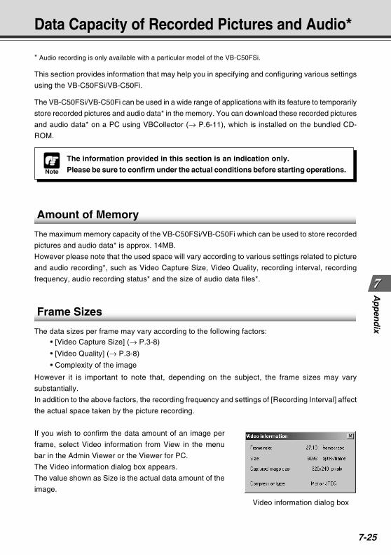
7-25
Ap
pen
dix
Data Capacity of Recorded Pictures and Audio*
Note
The information provided in this section is an indication only.
Please be sure to confirm under the actual conditions before starting operations.
* Audio recording is only available with a particular model of the VB-C50FSi.
This section provides information that may help you in specifying and configuring various settings
using the VB-C50FSi/VB-C50Fi.
The VB-C50FSi/VB-C50Fi can be used in a wide range of applications with its feature to temporarily
store recorded pictures and audio data* in the memory. You can download these recorded pictures
and audio data* on a PC using VBCollector (→ P.6-11), which is installed on the bundled CD-
ROM.
Amount of Memory
The maximum memory capacity of the VB-C50FSi/VB-C50Fi which can be used to store recorded
pictures and audio data* is approx. 14MB.
However please note that the used space will vary according to various settings related to picture
and audio recording*, such as Video Capture Size, Video Quality, recording interval, recording
frequency, audio recording status* and the size of audio data files*.
Frame Sizes
The data sizes per frame may vary according to the following factors:• [Video Capture Size] (→ P.3-8)
• [Video Quality] (→ P.3-8)
• Complexity of the image
However it is important to note that, depending on the subject, the frame sizes may vary
substantially.
In addition to the above factors, the recording frequency and settings of [Recording Interval] affect
the actual space taken by the picture recording.
If you wish to confirm the data amount of an image per
frame, select Video information from View in the menu
bar in the Admin Viewer or the Viewer for PC.
The Video information dialog box appears.
The value shown as Size is the actual data amount of the
image.
Video information dialog box
COPY
7-26
Data Capacity of Recorded Pictures & Audio
Amount of Audio Data*
Regardless of the volume, and even if there is no recorded audio data, the amount of audio data
is approx. 8KB per second.
Note
If you set the Video Quality to 100, the amount of data becomes enormously large.
The recorded pictures are saved in the VB-C50FSi/VB-C50Fi memory in units of
8KB. For example, an image data of 5KB takes the memory of 8KB, and an image
data of 10KB consumes the memory of 16KB.
NoteThe actual amount of audio data will vary according to the timing of recording.
COPY
7-27
Ap
pen
dix
Index
AAC adapter ........................................................... iv, 2-6AC cable ............................................................... iv, 2-6Access Control ......................................................... 3-20Account ............................................................. 4-5, 6-14Adding a Server ....................................................... 6-13Admin Viewer ........................................................... 4-61
Special Privilege .................................................. 4-61Starting Up ........................................................... 4-62Operating a Camera ............................................ 4-64Camera-Specific Functions ................................. 4-66Sending and Receiving Audio ............................. 4-67
Administration Tools ................................................ 3-28Advanced camera control ........................................ 4-64Apache ..................................................................... 5-21Applet Tag ................................................................ 5-20Area Ratio ................................................................. 4-42Area tab .................................................................... 4-41Audio
Transmission ....................................................... 3-18Input Volume ....................................................... 3-18Reception ............................................................. 3-19Output Volume ..................................................... 3-19Sending ................................................................ 4-67Playing ................................................................. 4-68
Audio button ............................................................. 4-68Audio Playback function .......................................... 4-57Audio Recording .................................... 4-34, 4-43, 4-55Audio Server ............................................................. 3-18Audio/Tracking Tab .................................................. 4-44Authorized User Account ......................................... 3-20Authorized/Restricted Host Specification ................ 3-21Auto Preset Tour ............................................ 3-13, 4-19Automatic Downloading ........................................... 6-21Automatic sensitivity setting .................................... 4-41
BBackground .............................................................. 5-16Backlight adjustment ................................................ 2-14Bitmap ...................................................................... 5-16Brightness ................................................................. 3-11
CCamera Control .......................................................... 3-9Camera Control Port ................................................ 3-17Camera Control Time ............................................... 3-17Camera Names ........................................................ 3-11Camera Parameter ................................................... 3-14Camera Server ......................................................... 3-17Camera Stabilization Time ............................. 3-17, 4-34Camera tab ............................................................... 4-40Camera-Specific Functions ...................................... 4-66Capacity warning message ...................................... 6-21
CD-ROM ...................................................... iv, 2-8, 2-13Check operation ....................................................... 2-11Connection Keeping ................................................... 3-7Control Queue Length .............................................. 3-17Custom Installation .................................................. 2-13
DDate .......................................................................... 3-23Date and Time .......................................................... 3-23Default Gateway Address .......................................... 3-6Detection area .......................................................... 4-41Detection indicator ................................................... 4-41Digital zoom .............................................................. 4-66DNS .......................................................................... 3-25Duration .................................................................... 4-42
EEasy Installation ....................................................... 2-13Echo Canceller ......................................................... 3-19E-mail Notifications .................................................. 4-56Error codes ............................................................... 4-59Ethernet ...................................................................... 3-6Ethernet connector ................................................... 1-10Events ....................................................................... 4-55Exposure .................................................................. 4-66External Device Input ............................................... 4-50
Display Screen .................................................... 4-50Setting Up ............................................................ 4-51Setting Notification .............................................. 4-62Displaying and Saving ......................................... 4-63
External Device Input Terminals ............................. 7-17External Device Names ........................................... 3-27External Device Output ............................................ 4-53
Display Screen .................................................... 4-53Setting Up ............................................................ 4-54Operating ............................................................. 4-63
External Device Output Terminals ........................... 7-17External Video Input ................................................... 3-9
FFactory Default Settings .......................................... 7-23
Restoring ............................................................. 7-21Filtering ..................................................................... 4-60Focus ........................................................................ 3-10Focus Mode ................................................................ 3-9Frame rate ................................................................ 4-40
GGain .......................................................................... 4-66GetStillImage ............................................................ 5-25Glimpse ............................................................ 5-4, 5-19Global Address ......................................................... 3-16
Example of Video Distribution ............................. 5-26
COPY
7-28
Index
HHome Position .......................................................... 3-11Host List .................................................................... 3-21Host Name .................................................................. 4-5Host Specification .................................................... 3-21HTTP Port ......................................................... 3-16, 4-5HTTP Server ............................................................ 3-16Hub .............................................................. 2-2, 2-6, 2-8
IInfrared Cut Filter ..................................................... 4-48Initial Setup Tool ........................................................ 2-8Install ........................................................................ 2-13Interlace Mode ........................................................... 3-9IP address .......................................................... 2-9, 3-6
LLAN cable ................................................................... 2-6LED ................................................................... 1-9, 3-27Live Mode ....................................................... 4-37, 4-47LiveApplet ......................................................... 5-4, 5-17Log .................................................................. 4-59, 6-32
Saving .................................................................. 4-59Copying ................................................................ 4-59Searching ................................................... 4-59, 6-34Selecting ........................................... 4-60, 6-33, 6-35
Log Events ............................................................... 3-29Log Messages ............................................................ 7-4
MMAC address ............................................................ 1-10Mail ........................................................................... 3-26Mail Address ............................................................. 3-26Maximum Connection Time ..................................... 3-15Maximum Frame Rate .............................................. 3-17Maximum Number of Clients ................................... 3-15Maximum Recording Time ....................................... 4-47Maximum Transmission Rate .................................. 3-17Maximum Transmission Unit ..................................... 3-6Microphone button ................................................... 4-67Microphone setting button ....................................... 4-67MIME type ................................................................ 5-21Mobile Phone ........................................................... 5-27Mode tab ................................................................... 4-37Monthly Calendar ..................................................... 4-28Motion Detected ....................................................... 4-46Motion Detection ...................................................... 4-37
Display Screen .................................................... 4-37Flow ..................................................................... 4-39Setting Up ............................................................ 4-40Setting Notification .............................................. 4-62Displaying and Saving ......................................... 4-63
Motion Detection area .................................... 4-38, 4-41Motion Detection status in the server ...................... 4-45
Multi-connector ......................................................... 1-10Multi-Terminal Module ............................................. 1-11
NName Server Address .............................................. 3-25Network Video Recorder VK-64 ................................ 1-8Night Mode ............................................................... 4-48
Display Screen .................................................... 4-48Setting Up ............................................................ 4-49Camera-Specific Functions ................................. 4-66
Normal Schedule ...................................................... 4-24Display Screen .................................................... 4-24Setting Up ............................................................ 4-25
NTP server ............................................................... 3-24
OOFF event .............................................. 4-43, 4-50, 4-55ON event ............................................... 4-43, 4-50, 4-55On-board File System Information .......................... 3-28Output tab ................................................................. 4-44
PPassword ......................................... 2-9, 3-5, 3-26, 6-14Peak Block ............................................................... 4-46Picture Recording ..................................................... 4-55PoE hub ........................................................ xiv, 2-6, 2-7POP before SMTP ................................................... 3-26POP Server .............................................................. 3-26Power connection socket ......................................... 1-10Preset ............................................................. 3-12, 4-13
Display Screen .................................................... 4-14Setting .................................................................. 4-16
Preset Name .................................................. 3-14, 4-15Preset Preview Frame ............................................. 4-16Preset Setting Area .................................................. 4-14Preset Tour ............................................................... 4-19
Setting .................................................................. 4-21Preset Tour Settings Area ....................................... 4-19Proxy ................................................................. 4-5, 6-14
QQ-factor ....................................................................... 3-8
RReboot ...................................................................... 3-29Reception Port No. ................................................... 6-21Recorded Images ..................................................... 6-23
Deleting ................................................................ 6-31Viewing ................................................................ 6-23
Recorded Picture ..................................................... 3-28Recording between ON event and OFF event ........ 4-43Recording interval between events ......................... 4-43Recording tab ........................................................... 4-43Repetition Interval .......................................... 4-35, 4-53
COPY
7-29
Ap
pen
dix
Index
Reset switch ................................................... 1-10, 7-22Restore Settings ....................................................... 3-29Restore to the previous Setting button ...................... 3-4Root Account .............................................................. 3-5
SSample Network Configurations .............................. 7-19Save Setting and Reboot button ............................... 3-4Save Setting button .................................................... 3-4Schedule name ........................................................ 4-24Schedule Setting ...................................................... 4-22Schedule tab .................................................. 4-25, 4-30Schedule track ......................................................... 4-24Screw hole for arm mounting ........................... 1-9, 1-10Screw hole for tripod mounting ................................ 1-10Self-timer .................................................................. 4-47Sensitivity ................................................................. 4-41Serial No. .................................................................. 1-10Server ....................................................................... 3-15Service ...................................................................... 4-33Service tab ..................................................... 4-26, 4-30Setting Up Service ................................................... 4-33Settings Tabs ........................................................... 4-38Settings Title Page ..................................................... 3-4Shade Correction ..................................................... 4-69Shared folder ............................................................ 6-14Shutter speed ............................................................. 3-9Slope Filter ............................................................... 3-18Slow Shutter ............................................................. 4-48Special Day Schedule .............................................. 4-28Special Schedule ..................................................... 4-28
Display Screen .................................................... 4-28Setting Up ............................................................ 4-29
Specifications ........................................................... 7-16Status List ................................................................... 4-9Subnet Mask ...................................................... 2-8, 3-6Sub-schedule track .................................................. 4-28System and Network .................................................. 3-5System component .................................................... 1-9System Configuration ............................................... 7-18
TTask .......................................................................... 6-16
Adding .................................................................. 6-16Editing .................................................................. 6-18Executing ............................................................. 6-18Canceling ............................................................. 6-18Checking .............................................................. 6-19
Task View ................................................................. 6-20TCP port number ...................................................... 3-17Time .......................................................................... 3-23Time Zone ................................................................ 3-24Timer ......................................................................... 4-34
Display Screen .................................................... 4-34Setting Up ............................................................ 4-36
Tour Schedule .......................................................... 3-13Troubleshooting ......................................................... 7-2
UUpgrading the Firmware .......................................... 7-20User List ................................................................... 3-20User name ........................................................ 2-9, 3-26
VVB Administration Tools ............................................ 4-2
Hardware and Software Requirements ................ 1-5Installing ................................................................. 4-2Starting Up ............................................................. 4-5
VB Initial Setup Tool .................................................. 2-8Hardware and Software Requirements ................ 1-5
VBAdmin Startup Panel ............................................. 4-6VBCollector .............................................................. 6-11
Hardware and Software Requirements ................ 1-5Installing ............................................................... 6-12Starting Up ........................................................... 6-13Older versions ............................................. 1-5, 6-12
VBCollector Image Viewer ....................................... 6-23VBSetup.exe .............................................................. 2-8VBToolsInstall.exe ................................................... 2-13Video Capture ............................................................ 3-8Video Capture Size .................................................... 3-8Video Mode .................................................... 4-37, 4-47Video Quality .............................................................. 3-8Video Recording ....................................................... 4-47Video Transmission Port .......................................... 3-17View Restriction ......................................................... 4-7
Display Screen ...................................................... 4-8Setting .................................................................. 4-10
View Restriction Preview Frame ...................... 4-8, 4-10Viewer ......................................................................... 5-4Viewer for Java ....................................... 2-14, 5-4, 7-18
Hardware and Software Requirements ................ 1-4Viewer for PC .......................................... 2-14, 5-5, 7-18
Hardware and Software Requirements ................ 1-4Viewer Software ....................................................... 2-14
WWeb page ................................................................... 5-2Web Pages for Video Distribution ............................. 5-2Web Server ............................................................... 5-21Weekly Calendar ...................................................... 4-24Wide Converter ................................................ 2-5, 3-11Wvh Files .................................................................. 5-22
ZZoom ......................................................................... 3-11
COPY
CANON INC. 30-2, Shimomaruko 3-chome, Ohta-ku, Tokyo 146-8501, Japan
U.S.A. CANON U.S.A.,INC. NEW JERSEY OFFICE100 Jamesburg Road, Jamesburg, NJ 08831 USA
CANON U.S.A.,INC. CHICAGO OFFICE100 Park Blvd., Itasca, IL 60143 USA
CANON U.S.A.,INC. LOS ANGELES OFFICE15955 Alton Parkway, Irvine, CA 92618 USA
CANON U.S.A.,INC. HONOLULU OFFICE 210 Ward Avenue, Suite 200 Honolulu, HI 96814 USA
If you have any questions, call the Canon U.S.A. InformationCenter toll-free at 1-800-828-4040 (U.S.A. only)
CANADA CANON CANADA INC. NATIONAL HEADQUARTERS6390 Dixie Road, Mississauga, Ontario L5T 1P7
CANON CANADA INC. CALGARY2828, 16th Street, N.E, Calgary, Alberta T2E 7K7
CANON CANADA INC. MONTRÉAL5990 Côte-de-Liesse, Montréal, Québec H4T 1V7
If you have any questions, call the CANON CANADA Customer InformationCentre toll-free at 1-800-OK-CANON (652-2666) (Canada only)
MEXICO CANON MEXICANA, S. DE R.L.DE C.V.Boulevard Manuel Avila Camacho, No. 138 PB, Pisos 15, 16 y 17Col Lomas de Chapultepec C.P. 11000 México, D.F. México
CENTRO YSURAMERICA CANON LATIN AMERICA, INC.
703 Waterford Way, Suite 400, Miami, FL 33126, USA
ASIA CANON SINGAPORE PTE. LTD.1 HarbourFront Avenue, #04-01, Keppel Bay Tower Singapore 098632
CANON HONGKONG CO., LTD.19/F., The Metropolis Tower, 10 Metropolis Drive, Hunghom, Kowloon, Hong Kong
OCEANIA CANON AUSTRALIA PTY.LTD.1 Thomas Holt Drive, North Ryde, Sydney, N.S.W. 2113, Australia
EUROPE CANON EUROPA N.V.Bovenkerkerweg 59-61, P.O. Box 2262, 1180 EG Amstelveen, The Netherlands
CANON EUROPE LTD.6 Roundwood Avenue, Stockley Park, Uxbridge Middlesex, UB11 1JA, United Kingdom
PUB.YT1-1354-005 © CANON INC. 2007 PRINTED IN JAPAN
COPY