Embed Size (px)
Citation preview
NetSure™ -48V DC Power System User Instructions
Section 5877 (Issue AQ, January 15, 2013)
SPEC. NO. MODEL
582140000 802NLDB 802NLEB 802NL-B
Business-Critical Continuity™, Emerson Network Power, and the Emerson Network Power logo are trademarks and service marks of Emerson Electric Co.
Lorain
® and Vortex
® are registered trademarks of Emerson
Network Power, Energy Systems, North America, Inc.
NetSure™, NetSpan™, NetReach™, NetXtend™, and NetPerform™ are trademarks of Emerson Network Power, Energy Systems, North America, Inc.
All other trademarks are the property of their respective owners.
The products covered by this instruction manual are manufactured and/or sold by Emerson Network Power, Energy Systems, North America, Inc.
The information contained in this document is subject to change without notice and may not be suitable for all applications. While every precaution has been taken to ensure the accuracy and completeness of this document, Emerson Network Power, Energy Systems, North America, Inc.
assumes no responsibility and disclaims all liability for damages resulting from use of this information or for any errors or omissions. Refer to other local practices or building codes as applicable for the correct
methods, tools, and materials to be used in performing procedures not specifically described in this document.
This document is the property of Emerson Network Power, Energy Systems, North America, Inc. and contains confidential and proprietary information owned by Emerson Network Power, Energy Systems, North America, Inc. Any copying, use or disclosure of it without the written permission
of Emerson Network Power, Energy Systems, North America, Inc. is strictly prohibited.
Copyright © 2013, Emerson Network Power, Energy Systems, North America, Inc.
All rights reserved throughout the world.
User Instructions Section 5877 Spec. No. 582140000 (Models 802NLDB, 802NLEB and 802NL-B) Issue AQ, January 15, 2013
Static Warning Page 1 of 2
This document is property of Emerson Network Power, Energy Systems, North America, Inc. and contains confidential and proprietary information owned by Emerson Network Power, Energy Systems, North America, Inc. Any copying, use, or disclosure of it without the written permission of Emerson Network Power, Energy Systems, North America, Inc. is strictly prohibited.
STATIC WARNING
The printed circuit cards used in this equipment contain static sensitive components. The warnings listed below must be observed to prevent damage to these components. Disregarding any of these warnings may result in personal injury or damage to the equipment.
1. Strictly adhere to the procedures provided in this document.
2. Before touching any static sensitive component or printed circuit card containing such a component, discharge all static electricity from yourself by wearing a wrist strap grounded through a one megohm resistor. Some wrist straps, such as Emerson Network Power Part Number 631810600, have a built-in one megohm resistor; no external resistor is necessary. Read and follow wrist strap manufacturer’s instructions outlining use of a specific wrist strap.
3. Do not touch the traces or components on a printed circuit card containing static sensitive components. Handle the printed circuit card only by the edges that do not have connector pads.
4. After removing a printed circuit card containing a static sensitive component, place the printed circuit card only on conductive or anti-static material such as conductive foam, conductive plastic, or aluminum foil. Do not use ordinary Styrofoam or ordinary plastic.
5. Store and ship static sensitive devices or printed circuit cards containing such components only in static shielding containers.
6. If necessary to repair a printed circuit card containing a static sensitive component, wear an appropriately grounded wrist strap, work on a conductive surface, use a grounded soldering iron, and use grounded test equipment.

Section 5877 User Instructions Issue AQ, January 15, 2013 Spec. No. 582140000 (Models 802NLDB, 802NLEB and 802NL-B)
Page 2 of 2 Static Warning
This document is property of Emerson Network Power, Energy Systems, North America, Inc. and contains confidential and proprietary information owned by Emerson Network Power, Energy Systems, North America, Inc. Any copying, use, or disclosure of it without the written permission of Emerson Network Power, Energy Systems, North America, Inc. is strictly prohibited.
This Page Intentionally Left Blank
User Instructions Section 5877 Spec. No. 582140000 (Models 802NLDB, 802NLEB and 802NL-B) Issue AQ, January 15, 2013
FCC Information Page 1 of 2
This document is property of Emerson Network Power, Energy Systems, North America, Inc. and contains confidential and proprietary information owned by Emerson Network Power, Energy Systems, North America, Inc. Any copying, use, or disclosure of it without the written permission of Emerson Network Power, Energy Systems, North America, Inc. is strictly prohibited.
FCC INFORMATION The MCA Interface Modem Option (if installed) has been granted a registration number by the Federal Communications Commission, under Part 68 rules and regulations for direct connection to the telephone lines. In order to comply with these FCC rules, the following instructions must be carefully read and applicable portions followed completely:
a) Direct connection to the telephone lines may be made only through the standard plug- ended cord furnished to the utility-installed jack. No connection may be made to party or coin phone lines. Prior to connecting the device to the telephone lines, you must:
b) Call your telephone company and inform them you have an FCC registered device you desire to connect to their telephone lines. Give them the number(s) of the line(s) to be used, the make and model of the device, the FCC registration number and ringer equivalence. This information will be found on the device or enclosed with instructions as well as the jack suitable for your device.
c) After the telephone company has been advised of the above you may connect your device if the jack is available, or after the telephone company has made the installation.
d) Repairs may be made only by the manufacturer or his authorized service agency. Unauthorized repairs void registration and warranty. Contact seller or manufacturer for details of permissible user performed routine repairs, and where and how to have other than routine repairs.
e) If, through abnormal circumstances, harm to the telephone lines is caused, it should be unplugged until it can be determined if your device or the telephone line is the source. If your device is the source, it should not be reconnected until necessary repairs are effected.
f) Should the telephone company notify you that your device is causing harm, the device should be unplugged. The telephone company will, where practicable, notify you, that temporary discontinuance of service may be required. However, where prior notice is not practicable, the telephone company may temporarily discontinue service, if such action is reasonably necessary, in such cases the telephone company must (A) Promptly notify you of such temporary discontinuance, (B) Afford you the opportunity to correct the condition and (C) Inform you of your rights to bring a complaint to the FCC under their rules.
g) The telephone company may make changes in its communications facilities, equipment, operations or procedures, where such action is reasonably required in the operation of its business and is not inconsistent with FCC rules. If such changes can be reasonably expected to render any customer’s devices incompatible with telephone company facilities, or require modification or alteration, or otherwise materially affect its performance, written notification must be given to the user, to allow uninterrupted service.
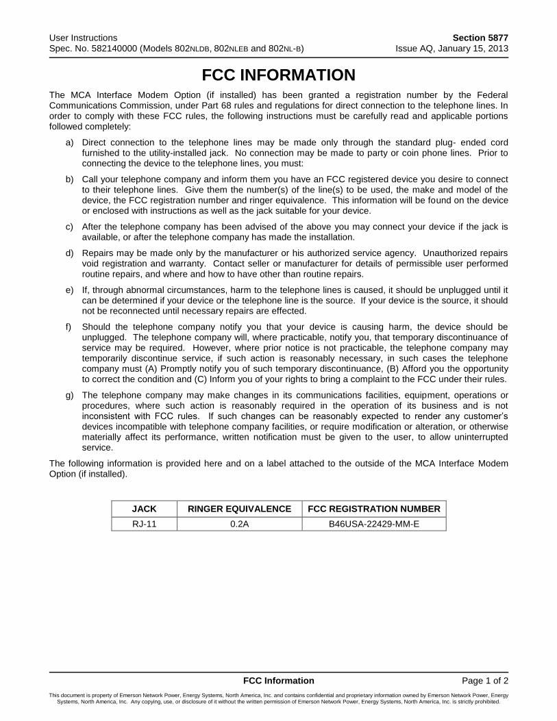
The following information is provided here and on a label attached to the outside of the MCA Interface Modem Option (if installed).
JACK RINGER EQUIVALENCE FCC REGISTRATION NUMBER
RJ-11 0.2A B46USA-22429-MM-E
Section 5877 User Instructions Issue AQ, January 15, 2013 Spec. No. 582140000 (Models 802NLDB, 802NLEB and 802NL-B)
Page 2 of 2 FCC Information
This document is property of Emerson Network Power, Energy Systems, North America, Inc. and contains confidential and proprietary information owned by Emerson Network Power, Energy Systems, North America, Inc. Any copying, use, or disclosure of it without the written permission of Emerson Network Power, Energy Systems, North America, Inc. is strictly prohibited.
This Page Intentionally Left Blank
User Instructions Section 5877 Spec. No. 582140000 (Models 802NLDB, 802NLEB and 802NL-B) Issue AQ, January 15, 2013
Table of Contents Page i
This document is property of Emerson Network Power, Energy Systems, North America, Inc. and contains confidential and proprietary information owned by Emerson Network Power, Energy Systems, North America, Inc. Any copying, use, or disclosure of it without the written permission of Emerson Network Power, Energy Systems, North America, Inc. is strictly prohibited.
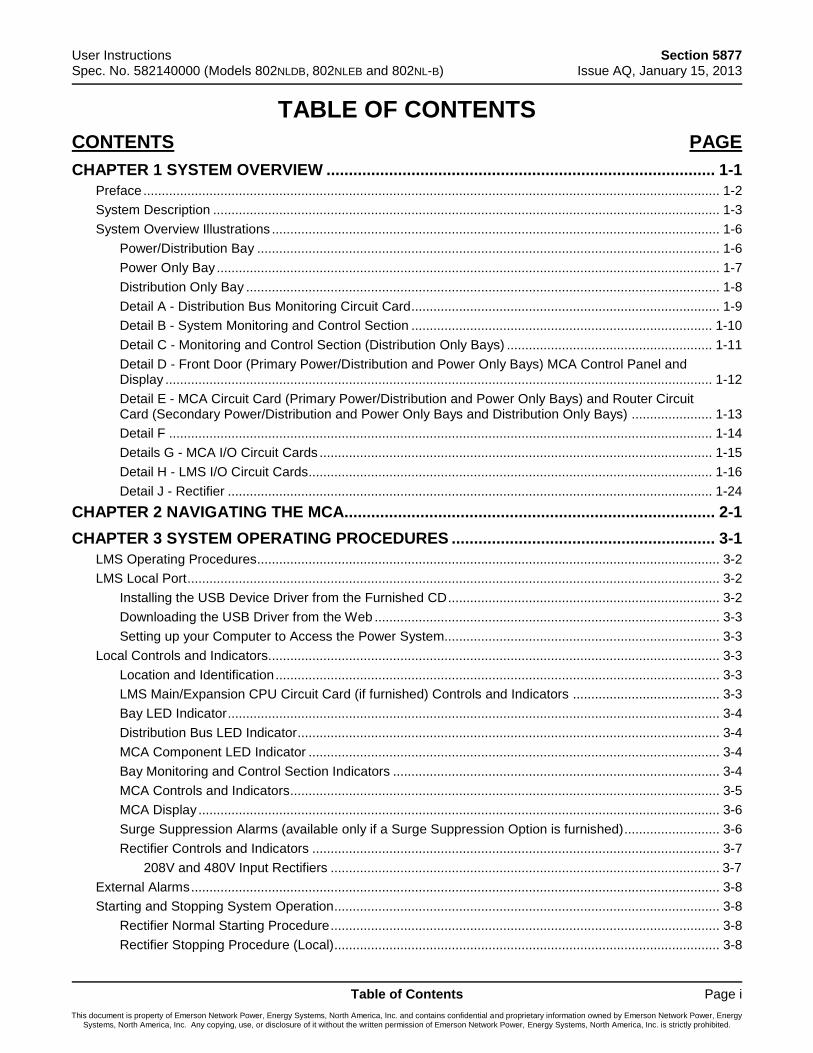
TABLE OF CONTENTS
CONTENTS PAGE
CHAPTER 1 SYSTEM OVERVIEW ....................................................................................... 1-1
Preface ............................................................................................................................................................. 1-2
System Description .......................................................................................................................................... 1-3
System Overview Illustrations .......................................................................................................................... 1-6
Power/Distribution Bay .............................................................................................................................. 1-6
Power Only Bay ......................................................................................................................................... 1-7
Distribution Only Bay ................................................................................................................................. 1-8
Detail A - Distribution Bus Monitoring Circuit Card .................................................................................... 1-9
Detail B - System Monitoring and Control Section .................................................................................. 1-10
Detail C - Monitoring and Control Section (Distribution Only Bays) ........................................................ 1-11
Detail D - Front Door (Primary Power/Distribution and Power Only Bays) MCA Control Panel and Display ..................................................................................................................................................... 1-12
Detail E - MCA Circuit Card (Primary Power/Distribution and Power Only Bays) and Router Circuit Card (Secondary Power/Distribution and Power Only Bays and Distribution Only Bays) ...................... 1-13
Detail F .................................................................................................................................................... 1-14
Details G - MCA I/O Circuit Cards ........................................................................................................... 1-15
Detail H - LMS I/O Circuit Cards .............................................................................................................. 1-16
Detail J - Rectifier .................................................................................................................................... 1-24
CHAPTER 2 NAVIGATING THE MCA................................................................................... 2-1
CHAPTER 3 SYSTEM OPERATING PROCEDURES ........................................................... 3-1
LMS Operating Procedures.............................................................................................................................. 3-2
LMS Local Port ................................................................................................................................................. 3-2
Installing the USB Device Driver from the Furnished CD .......................................................................... 3-2
Downloading the USB Driver from the Web .............................................................................................. 3-3
Setting up your Computer to Access the Power System........................................................................... 3-3
Local Controls and Indicators........................................................................................................................... 3-3
Location and Identification ......................................................................................................................... 3-3
LMS Main/Expansion CPU Circuit Card (if furnished) Controls and Indicators ........................................ 3-3
Bay LED Indicator ...................................................................................................................................... 3-4
Distribution Bus LED Indicator ................................................................................................................... 3-4
MCA Component LED Indicator ................................................................................................................ 3-4
Bay Monitoring and Control Section Indicators ......................................................................................... 3-4
MCA Controls and Indicators ..................................................................................................................... 3-5
MCA Display .............................................................................................................................................. 3-6
Surge Suppression Alarms (available only if a Surge Suppression Option is furnished) .......................... 3-6
Rectifier Controls and Indicators ............................................................................................................... 3-7
208V and 480V Input Rectifiers .......................................................................................................... 3-7
External Alarms ................................................................................................................................................ 3-8
Starting and Stopping System Operation ......................................................................................................... 3-8
Rectifier Normal Starting Procedure .......................................................................................................... 3-8
Rectifier Stopping Procedure (Local)......................................................................................................... 3-8

Section 5877 User Instructions Issue AQ, January 15, 2013 Spec. No. 582140000 (Models 802NLDB, 802NLEB and 802NL-B)
Page ii Table of Contents
This document is property of Emerson Network Power, Energy Systems, North America, Inc. and contains confidential and proprietary information owned by Emerson Network Power, Energy Systems, North America, Inc. Any copying, use, or disclosure of it without the written permission of Emerson Network Power, Energy Systems, North America, Inc. is strictly prohibited.
Complete Shutdown ............................................................................................................................ 3-8
Local TR Shutdown ............................................................................................................................. 3-8
Rectifier Stopping Procedure (Remote) (if optional LMS installed) ........................................................... 3-8
Restarting Procedures when Rectifier is Automatically or Manually Inhibited, Shut Down, or Locked Out .................................................................................................................................................................... 3-9
Rectifier High Voltage Shutdown Lockout ................................................................................................. 3-9
Rectifier Emergency Shutdown and Fire Alarm Disconnect ..................................................................... 3-9
Remote On/Off (TR) .................................................................................................................................. 3-9
Output Voltage Mode of Operation Selection .................................................................................................. 3-9
Placing the System into the Float Mode of Operation ............................................................................... 3-9
Placing the System into the Test/Equalize Mode of Operation ............................................................... 3-10
Method 1 (Manual Test/Equalize) Procedure ................................................................................... 3-10
Method 2 (Manually Initiated Timed Test/Equalize) Procedure ........................................................ 3-12
Method 3 (Automatic Test/Equalize) Procedure ............................................................................... 3-14
Method 4 (External Test/Equalize) Procedure .................................................................................. 3-16
Setting MCA Audible Alarm Cutoff Reset Time Period .................................................................................. 3-17
Procedure .......................................................................................................................................... 3-17
Setting Rectifier Sequencing Delay Time Period ........................................................................................... 3-18
Procedure .......................................................................................................................................... 3-18
Setting MCA Custom Text Messages (Names) ............................................................................................. 3-19
Procedure .......................................................................................................................................... 3-19
Mapping LMS LED Channels to the MCA Display and MCA Customer Alarm Relays ................................. 3-20
Procedure .......................................................................................................................................... 3-20
Using the Alarm Relay Test Feature .............................................................................................................. 3-20
MCA “Power Share” Feature.......................................................................................................................... 3-21
Description ............................................................................................................................................... 3-21
Operating Modes ..................................................................................................................................... 3-21
Low Load Operation .......................................................................................................................... 3-21
Normal Load Operation ..................................................................................................................... 3-21
High Load Operation ......................................................................................................................... 3-21
Overload Operation ........................................................................................................................... 3-21
Requirements and Conditions ................................................................................................................. 3-21
Programming the MCA Power Share Feature in the New Power System .............................................. 3-22
Enabling Power Share ...................................................................................................................... 3-22
Setting the Power Share Initial Capacity Limit .................................................................................. 3-22
Setting the Power Share Voltage Offset ........................................................................................... 3-23
Verifying the Operation of the Power Share Feature .............................................................................. 3-23
MCA “ALTERNATE CURRENT LIMIT” FEATURE ........................................................................................ 3-25
Description ............................................................................................................................................... 3-25
Operating Modes ..................................................................................................................................... 3-25
Normal Current Limit Operation ........................................................................................................ 3-25
Alternate Current Limit Operation ..................................................................................................... 3-25
Requirements and Conditions ................................................................................................................. 3-25
Programming the MCA Alternate Current Limit Feature ......................................................................... 3-25
Enabling Alternate Current Limit ....................................................................................................... 3-25
User Instructions Section 5877 Spec. No. 582140000 (Models 802NLDB, 802NLEB and 802NL-B) Issue AQ, January 15, 2013
Table of Contents Page iii
This document is property of Emerson Network Power, Energy Systems, North America, Inc. and contains confidential and proprietary information owned by Emerson Network Power, Energy Systems, North America, Inc. Any copying, use, or disclosure of it without the written permission of Emerson Network Power, Energy Systems, North America, Inc. is strictly prohibited.
Setting the Alternate Current Limit Initial Capacity Limit ................................................................... 3-26
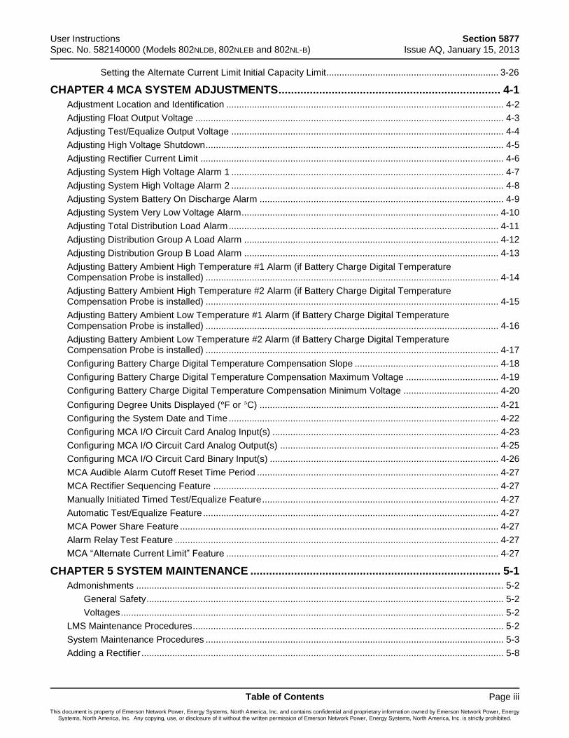
CHAPTER 4 MCA SYSTEM ADJUSTMENTS ....................................................................... 4-1
Adjustment Location and Identification ............................................................................................................ 4-2
Adjusting Float Output Voltage ........................................................................................................................ 4-3
Adjusting Test/Equalize Output Voltage .......................................................................................................... 4-4
Adjusting High Voltage Shutdown .................................................................................................................... 4-5
Adjusting Rectifier Current Limit ...................................................................................................................... 4-6
Adjusting System High Voltage Alarm 1 .......................................................................................................... 4-7
Adjusting System High Voltage Alarm 2 .......................................................................................................... 4-8
Adjusting System Battery On Discharge Alarm ............................................................................................... 4-9
Adjusting System Very Low Voltage Alarm .................................................................................................... 4-10
Adjusting Total Distribution Load Alarm ......................................................................................................... 4-11
Adjusting Distribution Group A Load Alarm ................................................................................................... 4-12
Adjusting Distribution Group B Load Alarm ................................................................................................... 4-13
Adjusting Battery Ambient High Temperature #1 Alarm (if Battery Charge Digital Temperature Compensation Probe is installed) .................................................................................................................. 4-14
Adjusting Battery Ambient High Temperature #2 Alarm (if Battery Charge Digital Temperature Compensation Probe is installed) .................................................................................................................. 4-15
Adjusting Battery Ambient Low Temperature #1 Alarm (if Battery Charge Digital Temperature Compensation Probe is installed) .................................................................................................................. 4-16
Adjusting Battery Ambient Low Temperature #2 Alarm (if Battery Charge Digital Temperature Compensation Probe is installed) .................................................................................................................. 4-17
Configuring Battery Charge Digital Temperature Compensation Slope ........................................................ 4-18
Configuring Battery Charge Digital Temperature Compensation Maximum Voltage .................................... 4-19
Configuring Battery Charge Digital Temperature Compensation Minimum Voltage ..................................... 4-20
Configuring Degree Units Displayed ( F or C) ............................................................................................. 4-21
Configuring the System Date and Time ......................................................................................................... 4-22
Configuring MCA I/O Circuit Card Analog Input(s) ........................................................................................ 4-23
Configuring MCA I/O Circuit Card Analog Output(s) ..................................................................................... 4-25
Configuring MCA I/O Circuit Card Binary Input(s) ......................................................................................... 4-26
MCA Audible Alarm Cutoff Reset Time Period .............................................................................................. 4-27
MCA Rectifier Sequencing Feature ............................................................................................................... 4-27
Manually Initiated Timed Test/Equalize Feature ............................................................................................ 4-27
Automatic Test/Equalize Feature ................................................................................................................... 4-27
MCA Power Share Feature ............................................................................................................................ 4-27
Alarm Relay Test Feature .............................................................................................................................. 4-27
MCA “Alternate Current Limit” Feature .......................................................................................................... 4-27
CHAPTER 5 SYSTEM MAINTENANCE ................................................................................ 5-1
Admonishments ............................................................................................................................................... 5-2
General Safety ........................................................................................................................................... 5-2
Voltages ..................................................................................................................................................... 5-2
LMS Maintenance Procedures ......................................................................................................................... 5-2
System Maintenance Procedures .................................................................................................................... 5-3
Adding a Rectifier ............................................................................................................................................. 5-8
Section 5877 User Instructions Issue AQ, January 15, 2013 Spec. No. 582140000 (Models 802NLDB, 802NLEB and 802NL-B)
Page iv Table of Contents
This document is property of Emerson Network Power, Energy Systems, North America, Inc. and contains confidential and proprietary information owned by Emerson Network Power, Energy Systems, North America, Inc. Any copying, use, or disclosure of it without the written permission of Emerson Network Power, Energy Systems, North America, Inc. is strictly prohibited.
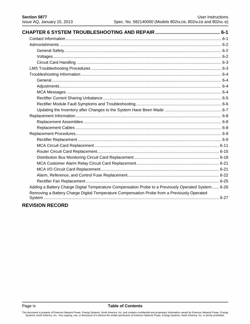
CHAPTER 6 SYSTEM TROUBLESHOOTING AND REPAIR ............................................... 6-1
Contact Information .......................................................................................................................................... 6-1
Admonishments ............................................................................................................................................... 6-2
General Safety ........................................................................................................................................... 6-2
Voltages ..................................................................................................................................................... 6-2
Circuit Card Handling ................................................................................................................................ 6-3
LMS Troubleshooting Procedures ................................................................................................................... 6-3
Troubleshooting Information ............................................................................................................................ 6-4
General ...................................................................................................................................................... 6-4
Adjustments ............................................................................................................................................... 6-4
MCA Messages ......................................................................................................................................... 6-4
Rectifier Current Sharing Unbalance ......................................................................................................... 6-5
Rectifier Module Fault Symptoms and Troubleshooting............................................................................ 6-6
Updating the Inventory after Changes to the System Have Been Made .................................................. 6-7
Replacement Information ................................................................................................................................. 6-8
Replacement Assemblies .......................................................................................................................... 6-8
Replacement Cables ................................................................................................................................. 6-8
Replacement Procedures ................................................................................................................................. 6-9
Rectifier Replacement ............................................................................................................................... 6-9
MCA Circuit Card Replacement .............................................................................................................. 6-11
Router Circuit Card Replacement............................................................................................................ 6-15
Distribution Bus Monitoring Circuit Card Replacement ........................................................................... 6-18
MCA Customer Alarm Relay Circuit Card Replacement ......................................................................... 6-21
MCA I/O Circuit Card Replacement ......................................................................................................... 6-21
Alarm, Reference, and Control Fuse Replacement ................................................................................. 6-22
Rectifier Fan Replacement ...................................................................................................................... 6-25
Adding a Battery Charge Digital Temperature Compensation Probe to a Previously Operated System ...... 6-26
Removing a Battery Charge Digital Temperature Compensation Probe from a Previously Operated System ........................................................................................................................................................... 6-27
REVISION RECORD
User Instructions Section 5877 Spec. No. 582140000 (Models 802NLDB, 802NLEB and 802NL-B) Issue AQ, January 15, 2013
Chapter 1. System Overview Page 1-1
This document is property of Emerson Network Power, Energy Systems, North America, Inc. and contains confidential and proprietary information owned by Emerson Network Power, Energy Systems, North America, Inc. Any copying, use, or disclosure of it without the written permission of Emerson Network Power, Energy Systems, North America, Inc. is strictly prohibited.
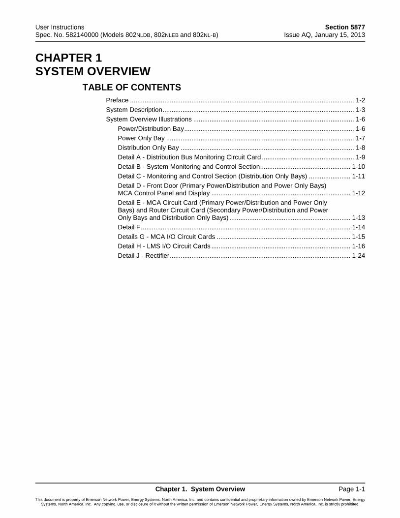
CHAPTER 1 SYSTEM OVERVIEW
TABLE OF CONTENTS
Preface ............................................................................................................................ 1-2
System Description .......................................................................................................... 1-3
System Overview Illustrations ......................................................................................... 1-6
Power/Distribution Bay .............................................................................................. 1-6
Power Only Bay ........................................................................................................ 1-7
Distribution Only Bay ................................................................................................ 1-8
Detail A - Distribution Bus Monitoring Circuit Card ................................................... 1-9
Detail B - System Monitoring and Control Section .................................................. 1-10
Detail C - Monitoring and Control Section (Distribution Only Bays) ....................... 1-11
Detail D - Front Door (Primary Power/Distribution and Power Only Bays) MCA Control Panel and Display ............................................................................. 1-12
Detail E - MCA Circuit Card (Primary Power/Distribution and Power Only Bays) and Router Circuit Card (Secondary Power/Distribution and Power Only Bays and Distribution Only Bays) ................................................................... 1-13
Detail F .................................................................................................................... 1-14
Details G - MCA I/O Circuit Cards .......................................................................... 1-15
Detail H - LMS I/O Circuit Cards ............................................................................. 1-16
Detail J - Rectifier .................................................................................................... 1-24
Section 5877 User Instructions Issue AQ, January 15, 2013 Spec. No. 582140000 (Models 802NLDB, 802NLEB and 802NL-B)
Page 1-2 Chapter 1. System Overview
This document is property of Emerson Network Power, Energy Systems, North America, Inc. and contains confidential and proprietary information owned by Emerson Network Power, Energy Systems, North America, Inc. Any copying, use, or disclosure of it without the written permission of Emerson Network Power, Energy Systems, North America, Inc. is strictly prohibited.
PREFACE
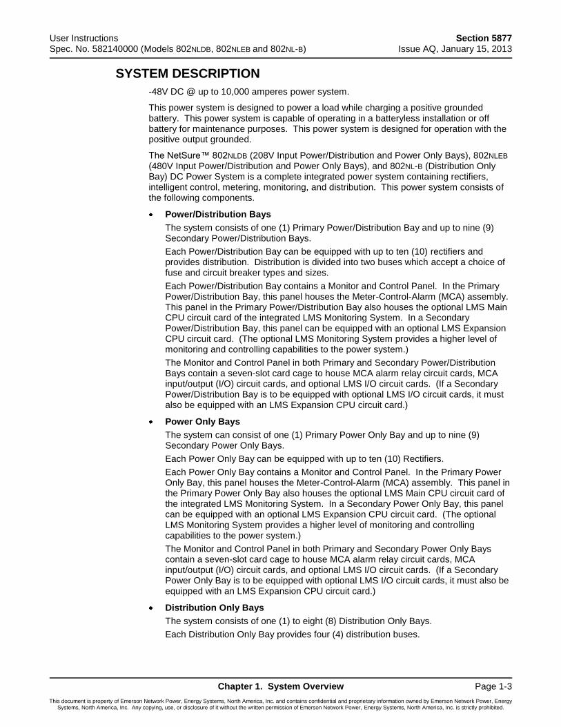
This document (Section 5877) provides User Instructions for NetSure™ Power System Model 802NLDB (208V Input Power/Distribution and Power Only Bays), 802NLEB (480V Input Power/Distribution and Power Only Bays) and 802NL-B (Distribution Only Bay); Spec. No. 582140000.
For an Installation Guide, refer to Section 5957 located in the separate INSTALLATION MANUAL. This is a condensed version of the Installation Instructions (Section 5876). Section 5876 can be accessed via the CD (Electronic Documentation Package) furnished with your system.
Refer to SAG582140000 (System Application Guide) for additional information. The SAG can be accessed via the CD (Electronic Documentation Package) furnished with your system.
For a color MCA Menu Tree, refer to Section 5886. Section 5886 is provided in the separate INSTALLATION MANUAL and the CD CARRIER MANUAL (it is also provided on the CD).
Your power system may contain an optional LMS Monitoring System, refer to Section 5879 (LMS1000 Installation Instructions) and Section 5847 (LMS1000 User Instructions) provided on the CD (Electronic Documentation Package) furnished with your system.
User Instructions Section 5877 Spec. No. 582140000 (Models 802NLDB, 802NLEB and 802NL-B) Issue AQ, January 15, 2013
Chapter 1. System Overview Page 1-3
This document is property of Emerson Network Power, Energy Systems, North America, Inc. and contains confidential and proprietary information owned by Emerson Network Power, Energy Systems, North America, Inc. Any copying, use, or disclosure of it without the written permission of Emerson Network Power, Energy Systems, North America, Inc. is strictly prohibited.
SYSTEM DESCRIPTION
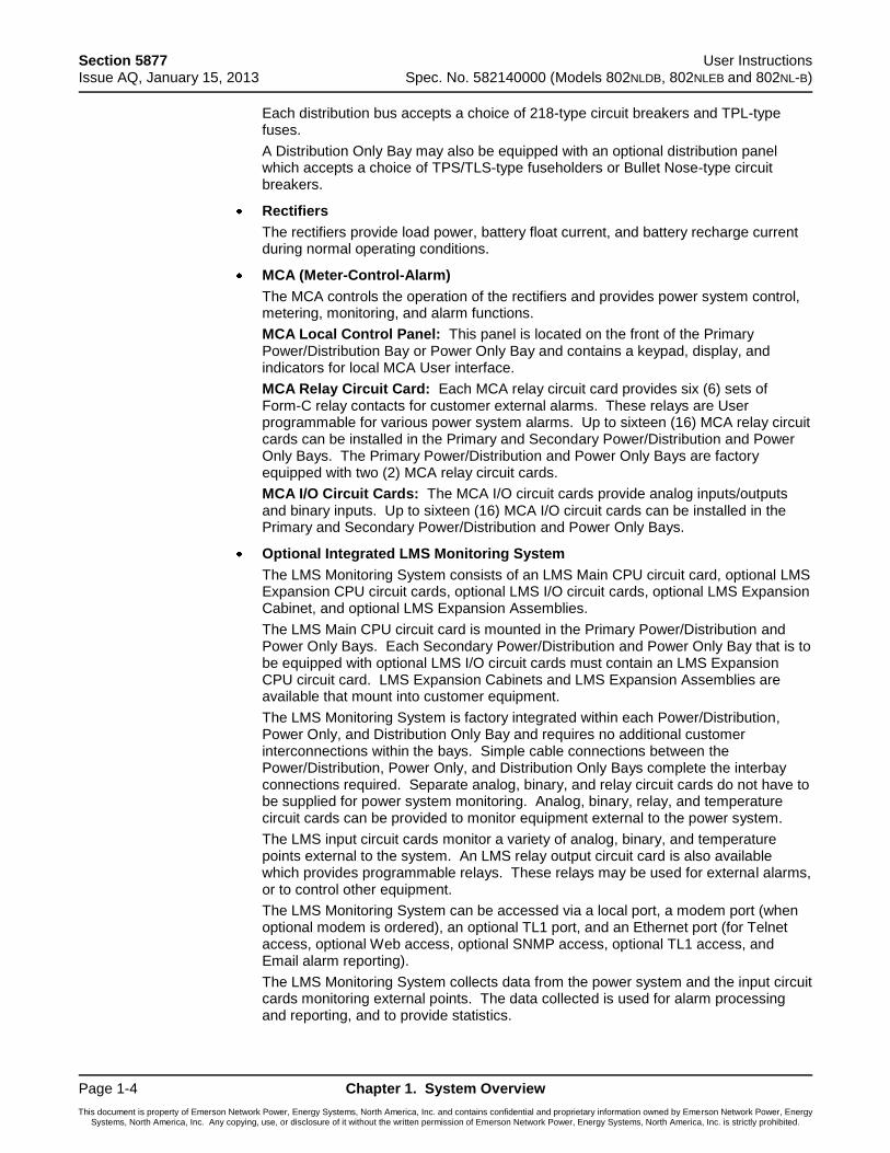
-48V DC @ up to 10,000 amperes power system.
This power system is designed to power a load while charging a positive grounded battery. This power system is capable of operating in a batteryless installation or off battery for maintenance purposes. This power system is designed for operation with the positive output grounded.
The NetSure™ 802NLDB (208V Input Power/Distribution and Power Only Bays), 802NLEB (480V Input Power/Distribution and Power Only Bays), and 802NL-B (Distribution Only Bay) DC Power System is a complete integrated power system containing rectifiers, intelligent control, metering, monitoring, and distribution. This power system consists of the following components.
Power/Distribution Bays
The system consists of one (1) Primary Power/Distribution Bay and up to nine (9) Secondary Power/Distribution Bays.
Each Power/Distribution Bay can be equipped with up to ten (10) rectifiers and provides distribution. Distribution is divided into two buses which accept a choice of fuse and circuit breaker types and sizes.
Each Power/Distribution Bay contains a Monitor and Control Panel. In the Primary Power/Distribution Bay, this panel houses the Meter-Control-Alarm (MCA) assembly. This panel in the Primary Power/Distribution Bay also houses the optional LMS Main CPU circuit card of the integrated LMS Monitoring System. In a Secondary Power/Distribution Bay, this panel can be equipped with an optional LMS Expansion CPU circuit card. (The optional LMS Monitoring System provides a higher level of monitoring and controlling capabilities to the power system.)
The Monitor and Control Panel in both Primary and Secondary Power/Distribution Bays contain a seven-slot card cage to house MCA alarm relay circuit cards, MCA input/output (I/O) circuit cards, and optional LMS I/O circuit cards. (If a Secondary Power/Distribution Bay is to be equipped with optional LMS I/O circuit cards, it must also be equipped with an LMS Expansion CPU circuit card.)
Power Only Bays
The system can consist of one (1) Primary Power Only Bay and up to nine (9) Secondary Power Only Bays.
Each Power Only Bay can be equipped with up to ten (10) Rectifiers.
Each Power Only Bay contains a Monitor and Control Panel. In the Primary Power Only Bay, this panel houses the Meter-Control-Alarm (MCA) assembly. This panel in the Primary Power Only Bay also houses the optional LMS Main CPU circuit card of the integrated LMS Monitoring System. In a Secondary Power Only Bay, this panel can be equipped with an optional LMS Expansion CPU circuit card. (The optional LMS Monitoring System provides a higher level of monitoring and controlling capabilities to the power system.)
The Monitor and Control Panel in both Primary and Secondary Power Only Bays contain a seven-slot card cage to house MCA alarm relay circuit cards, MCA input/output (I/O) circuit cards, and optional LMS I/O circuit cards. (If a Secondary Power Only Bay is to be equipped with optional LMS I/O circuit cards, it must also be equipped with an LMS Expansion CPU circuit card.)
Distribution Only Bays
The system consists of one (1) to eight (8) Distribution Only Bays.
Each Distribution Only Bay provides four (4) distribution buses.
Section 5877 User Instructions Issue AQ, January 15, 2013 Spec. No. 582140000 (Models 802NLDB, 802NLEB and 802NL-B)
Page 1-4 Chapter 1. System Overview
This document is property of Emerson Network Power, Energy Systems, North America, Inc. and contains confidential and proprietary information owned by Emerson Network Power, Energy Systems, North America, Inc. Any copying, use, or disclosure of it without the written permission of Emerson Network Power, Energy Systems, North America, Inc. is strictly prohibited.
Each distribution bus accepts a choice of 218-type circuit breakers and TPL-type fuses.
A Distribution Only Bay may also be equipped with an optional distribution panel which accepts a choice of TPS/TLS-type fuseholders or Bullet Nose-type circuit breakers.
Rectifiers
The rectifiers provide load power, battery float current, and battery recharge current during normal operating conditions.
MCA (Meter-Control-Alarm)
The MCA controls the operation of the rectifiers and provides power system control, metering, monitoring, and alarm functions.
MCA Local Control Panel: This panel is located on the front of the Primary Power/Distribution Bay or Power Only Bay and contains a keypad, display, and indicators for local MCA User interface.
MCA Relay Circuit Card: Each MCA relay circuit card provides six (6) sets of Form-C relay contacts for customer external alarms. These relays are User programmable for various power system alarms. Up to sixteen (16) MCA relay circuit cards can be installed in the Primary and Secondary Power/Distribution and Power Only Bays. The Primary Power/Distribution and Power Only Bays are factory equipped with two (2) MCA relay circuit cards.
MCA I/O Circuit Cards: The MCA I/O circuit cards provide analog inputs/outputs and binary inputs. Up to sixteen (16) MCA I/O circuit cards can be installed in the Primary and Secondary Power/Distribution and Power Only Bays.
Optional Integrated LMS Monitoring System
The LMS Monitoring System consists of an LMS Main CPU circuit card, optional LMS Expansion CPU circuit cards, optional LMS I/O circuit cards, optional LMS Expansion Cabinet, and optional LMS Expansion Assemblies.
The LMS Main CPU circuit card is mounted in the Primary Power/Distribution and Power Only Bays. Each Secondary Power/Distribution and Power Only Bay that is to be equipped with optional LMS I/O circuit cards must contain an LMS Expansion CPU circuit card. LMS Expansion Cabinets and LMS Expansion Assemblies are available that mount into customer equipment.
The LMS Monitoring System is factory integrated within each Power/Distribution, Power Only, and Distribution Only Bay and requires no additional customer interconnections within the bays. Simple cable connections between the Power/Distribution, Power Only, and Distribution Only Bays complete the interbay connections required. Separate analog, binary, and relay circuit cards do not have to be supplied for power system monitoring. Analog, binary, relay, and temperature circuit cards can be provided to monitor equipment external to the power system.
The LMS input circuit cards monitor a variety of analog, binary, and temperature points external to the system. An LMS relay output circuit card is also available which provides programmable relays. These relays may be used for external alarms, or to control other equipment.
The LMS Monitoring System can be accessed via a local port, a modem port (when optional modem is ordered), an optional TL1 port, and an Ethernet port (for Telnet access, optional Web access, optional SNMP access, optional TL1 access, and Email alarm reporting).
The LMS Monitoring System collects data from the power system and the input circuit cards monitoring external points. The data collected is used for alarm processing and reporting, and to provide statistics.
User Instructions Section 5877 Spec. No. 582140000 (Models 802NLDB, 802NLEB and 802NL-B) Issue AQ, January 15, 2013
Chapter 1. System Overview Page 1-5
This document is property of Emerson Network Power, Energy Systems, North America, Inc. and contains confidential and proprietary information owned by Emerson Network Power, Energy Systems, North America, Inc. Any copying, use, or disclosure of it without the written permission of Emerson Network Power, Energy Systems, North America, Inc. is strictly prohibited.
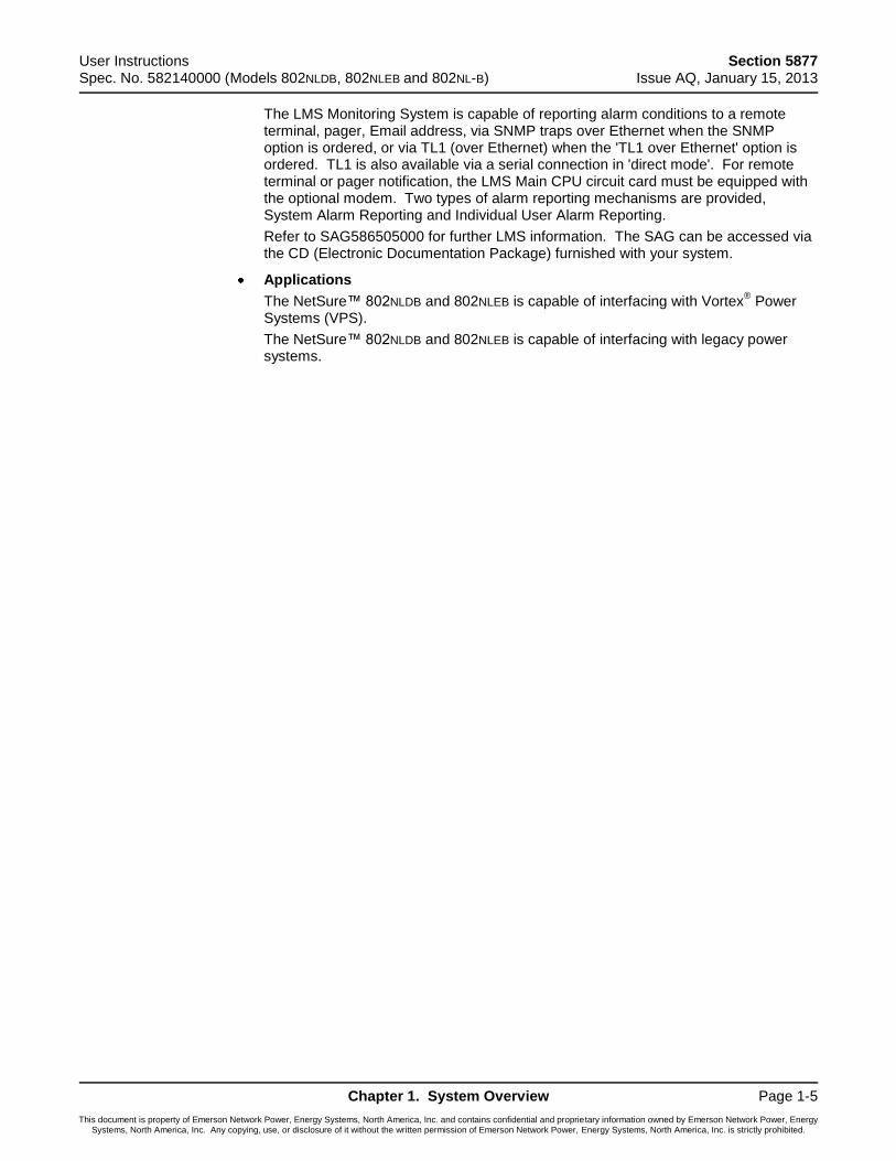
The LMS Monitoring System is capable of reporting alarm conditions to a remote terminal, pager, Email address, via SNMP traps over Ethernet when the SNMP option is ordered, or via TL1 (over Ethernet) when the 'TL1 over Ethernet' option is ordered. TL1 is also available via a serial connection in 'direct mode'. For remote terminal or pager notification, the LMS Main CPU circuit card must be equipped with the optional modem. Two types of alarm reporting mechanisms are provided, System Alarm Reporting and Individual User Alarm Reporting.
Refer to SAG586505000 for further LMS information. The SAG can be accessed via the CD (Electronic Documentation Package) furnished with your system.
Applications
The NetSure™ 802NLDB and 802NLEB is capable of interfacing with Vortex® Power
Systems (VPS).
The NetSure™ 802NLDB and 802NLEB is capable of interfacing with legacy power systems.
Section 5877 User Instructions Issue AQ, January 15, 2013 Spec. No. 582140000 (Models 802NLDB, 802NLEB and 802NL-B)
Page 1-6 Chapter 1. System Overview
This document is property of Emerson Network Power, Energy Systems, North America, Inc. and contains confidential and proprietary information owned by Emerson Network Power, Energy Systems, North America, Inc. Any copying, use, or disclosure of it without the written permission of Emerson Network Power, Energy Systems, North America, Inc. is strictly prohibited.
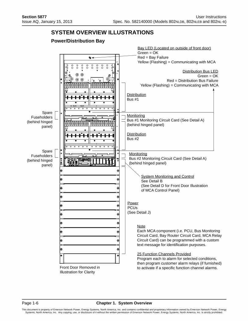
SYSTEM OVERVIEW ILLUSTRATIONS
Power/Distribution Bay
Bay LED (Located on outside of front door)
Green = OK
Red = Bay Failure
Yellow (Flashing) = Communicating with MCA
Spare
Fuseholders
(behind hinged
panel)
Spare
Fuseholders
(behind hinged
panel)
Front Door Removed in
Illustration for Clarity
Note
Each MCA component (i.e. PCU, Bus Monitoring
Circuit Card, Bay Router Circuit Card, MCA Relay
Circuit Card) can be programmed with a custom
text message for identification purposes.
25 Function Channels Provided
Program each to alarm for selected conditions,
then program customer alarm relays (if furnished)
to activate if a specific function channel alarms.
Power
PCUs
(See Detail J)
System Monitoring and Control
See Detail B
(See Detail D for Front Door Illustration
of MCA Control Panel)
Monitoring
Bus #1 Monitoring Circuit Card (See Detail A)
(behind hinged panel)
Monitoring
Bus #2 Monitoring Circuit Card (See Detail A)
(behind hinged panel)
Distribution
Bus #1
Distribution
Bus #2
Distribution Bus LED
Green = OK
Red = Distribution Bus Failure
Yellow (Flashing) = Communicating with MCA
User Instructions Section 5877 Spec. No. 582140000 (Models 802NLDB, 802NLEB and 802NL-B) Issue AQ, January 15, 2013
Chapter 1. System Overview Page 1-7
This document is property of Emerson Network Power, Energy Systems, North America, Inc. and contains confidential and proprietary information owned by Emerson Network Power, Energy Systems, North America, Inc. Any copying, use, or disclosure of it without the written permission of Emerson Network Power, Energy Systems, North America, Inc. is strictly prohibited.
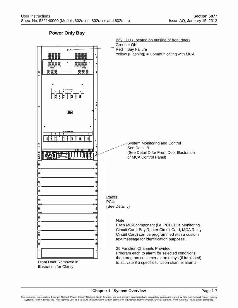
Power Only Bay
Bay LED (Located on outside of front door)
Green = OK
Red = Bay Failure
Yellow (Flashing) = Communicating with MCA
Front Door Removed in
Illustration for Clarity
Note
Each MCA component (i.e. PCU, Bus Monitoring
Circuit Card, Bay Router Circuit Card, MCA Relay
Circuit Card) can be programmed with a custom
text message for identification purposes.
25 Function Channels Provided
Program each to alarm for selected conditions,
then program customer alarm relays (if furnished)
to activate if a specific function channel alarms.
Power
PCUs
(See Detail J)
System Monitoring and Control
See Detail B
(See Detail D for Front Door Illustration
of MCA Control Panel)
Section 5877 User Instructions Issue AQ, January 15, 2013 Spec. No. 582140000 (Models 802NLDB, 802NLEB and 802NL-B)
Page 1-8 Chapter 1. System Overview
This document is property of Emerson Network Power, Energy Systems, North America, Inc. and contains confidential and proprietary information owned by Emerson Network Power, Energy Systems, North America, Inc. Any copying, use, or disclosure of it without the written permission of Emerson Network Power, Energy Systems, North America, Inc. is strictly prohibited.
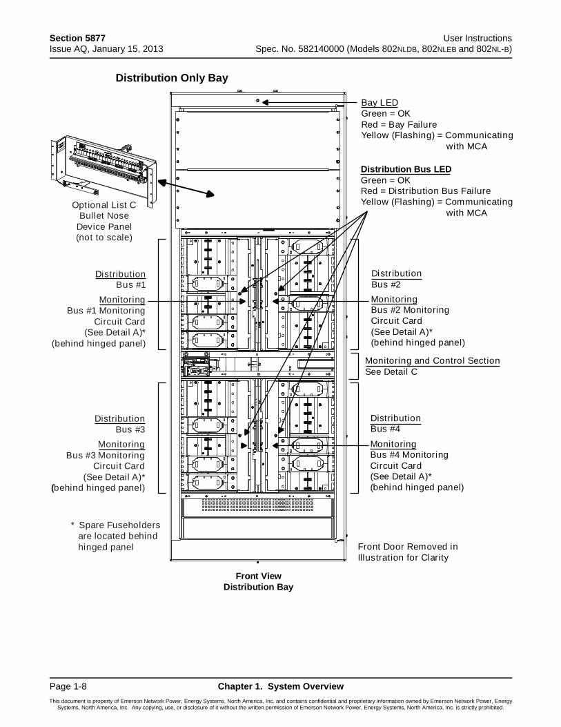
Distribution Only Bay
Optional List C
Bullet Nose
Device Panel(not to scale)
Distribution
Bus #1
Monitoring
Bus #1 Monitoring
Circuit Card(See Detail A)*
(behind hinged panel)
Distribution
Bus #3
Monitoring
Bus #3 Monitoring
Circui t Card
(See Detail A)*
(behind hinged panel)
Distribution
Bus #2
Monitoring
Bus #2 Monitoring
Circuit Card
(See Detail A)*
(behind hinged panel)
Distribution
Bus #4
Monitoring
Bus #4 Monitoring
Circuit Card
(See Detail A)*
(behind hinged panel)
Bay LED
Green = OK
Red = Bay FailureYellow (Flashing) = Communicating
with MCA
Distribution Bus LED
Green = OKRed = Distribution Bus Failure
Yellow (Flashing) = Communicating
with MCA
Monitoring and Control Section
See Detail C
Front Door Removed in
Illustration for Clarity
* Spare Fuseholders
are located behind
hinged panel
Front View
Distribution Bay
User Instructions Section 5877 Spec. No. 582140000 (Models 802NLDB, 802NLEB and 802NL-B) Issue AQ, January 15, 2013
Chapter 1. System Overview Page 1-9
This document is property of Emerson Network Power, Energy Systems, North America, Inc. and contains confidential and proprietary information owned by Emerson Network Power, Energy Systems, North America, Inc. Any copying, use, or disclosure of it without the written permission of Emerson Network Power, Energy Systems, North America, Inc. is strictly prohibited.
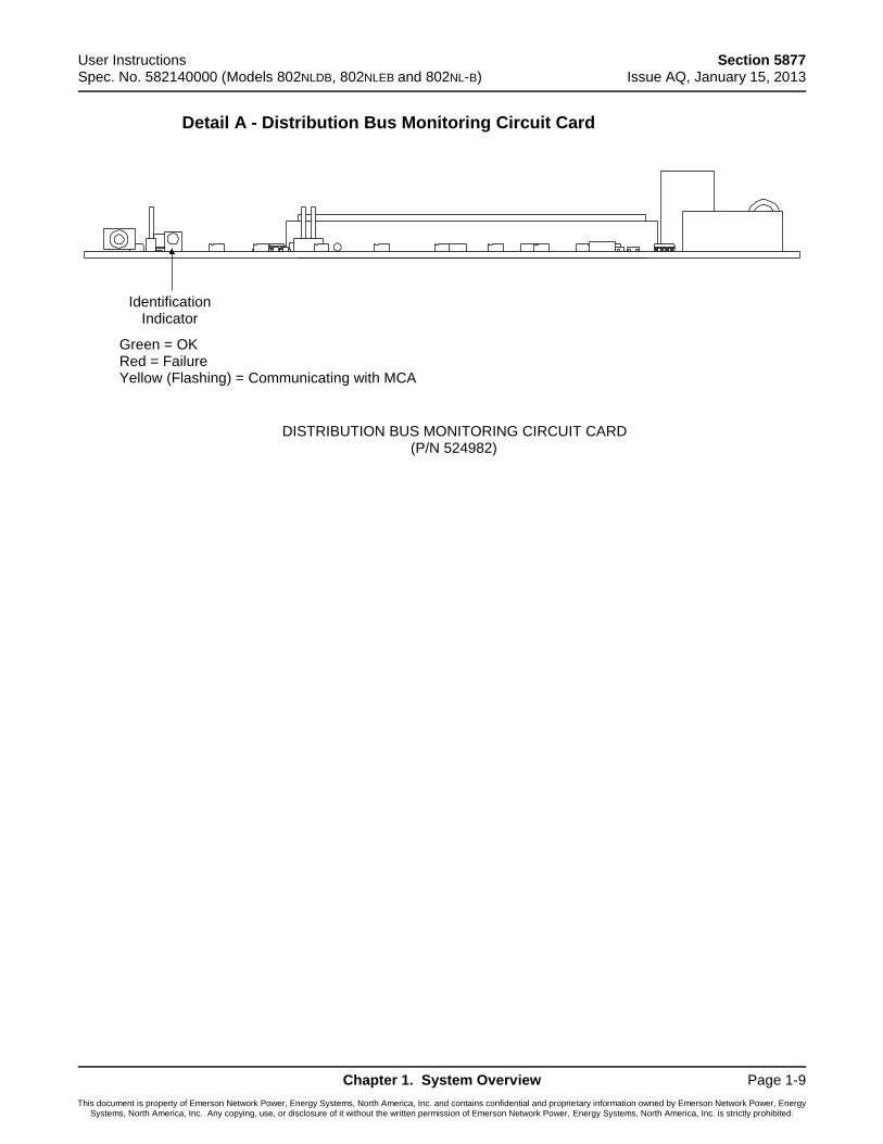
Detail A - Distribution Bus Monitoring Circuit Card
DISTRIBUTION BUS MONITORING CIRCUIT CARD(P/N 524982)
IdentificationIndicator
Green = OKRed = FailureYellow (Flashing) = Communicating with MCA
Section 5877 User Instructions Issue AQ, January 15, 2013 Spec. No. 582140000 (Models 802NLDB, 802NLEB and 802NL-B)
Page 1-10 Chapter 1. System Overview
This document is property of Emerson Network Power, Energy Systems, North America, Inc. and contains confidential and proprietary information owned by Emerson Network Power, Energy Systems, North America, Inc. Any copying, use, or disclosure of it without the written permission of Emerson Network Power, Energy Systems, North America, Inc. is strictly prohibited.
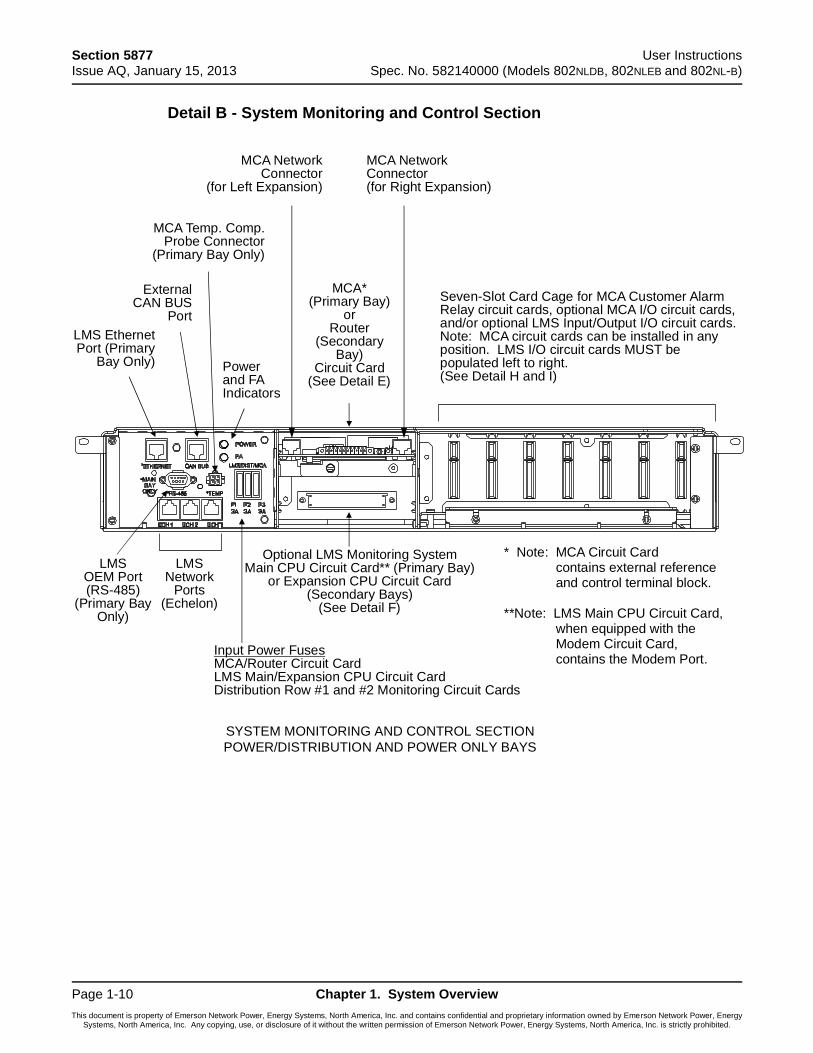
Detail B - System Monitoring and Control Section
SYSTEM MONITORING AND CONTROL SECTION
POWER/DISTRIBUTION AND POWER ONLY BAYS
Input Power FusesMCA/Router Circuit CardLMS Main/Expansion CPU Circuit CardDistribution Row #1 and #2 Monitoring Circuit Cards
Powerand FAIndicators
LMS EthernetPort (Primary
Bay Only)
MCA*(Primary Bay)
orRouter
(SecondaryBay)
Circuit Card(See Detail E)
LMSOEM Port(RS-485)
(Primary BayOnly)
LMSNetwork
Ports(Echelon)
MCA Temp. Comp.Probe Connector
(Primary Bay Only)
Optional LMS Monitoring SystemMain CPU Circuit Card** (Primary Bay)
or Expansion CPU Circuit Card(Secondary Bays)
(See Detail F)
Seven-Slot Card Cage for MCA Customer AlarmRelay circuit cards, optional MCA I/O circuit cards,and/or optional LMS Input/Output I/O circuit cards.Note: MCA circuit cards can be installed in anyposition. LMS I/O circuit cards MUST bepopulated left to right.(See Detail H and I)
ExternalCAN BUS
Port
MCA NetworkConnector
(for Left Expansion)
MCA NetworkConnector(for Right Expansion)
* Note: MCA Circuit Cardcontains external referenceand control terminal block.
**Note: LMS Main CPU Circuit Card,when equipped with theModem Circuit Card,contains the Modem Port.

User Instructions Section 5877 Spec. No. 582140000 (Models 802NLDB, 802NLEB and 802NL-B) Issue AQ, January 15, 2013
Chapter 1. System Overview Page 1-11
This document is property of Emerson Network Power, Energy Systems, North America, Inc. and contains confidential and proprietary information owned by Emerson Network Power, Energy Systems, North America, Inc. Any copying, use, or disclosure of it without the written permission of Emerson Network Power, Energy Systems, North America, Inc. is strictly prohibited.
Detail C - Monitoring and Control Section (Distribution Only Bays)
Section 5877 User Instructions Issue AQ, January 15, 2013 Spec. No. 582140000 (Models 802NLDB, 802NLEB and 802NL-B)
Page 1-12 Chapter 1. System Overview
This document is property of Emerson Network Power, Energy Systems, North America, Inc. and contains confidential and proprietary information owned by Emerson Network Power, Energy Systems, North America, Inc. Any copying, use, or disclosure of it without the written permission of Emerson Network Power, Energy Systems, North America, Inc. is strictly prohibited.
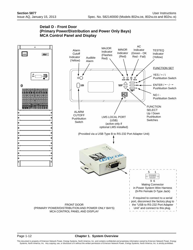
Detail D - Front Door (Primary Power/Distribution and Power Only Bays) MCA Control Panel and Display
Alarm
Cutoff
Indicator
(Yellow)
FUNCTION SET
YES / + / i
Pushbutton Switch
ENTER / /
Pushbutton Switch
NO / -
Pushbutton Switch
ALARM
CUTOFF
Pushbutton
Switch
FUNCTION
SELECT
Up / Down
Pushbutton
Switches
TESTEQ
Indicator
(Yellow)
AC
Indicator
(Green - OK
Red - Fail)
MINOR
Indicator
(Red)
MAJOR
Indicator
(Flashes
Red)Audible
Alarm
FRONT DOOR
(PRIMARY POWER/DISTRIBUTION AND POWER ONLY BAYS)
MCA CONTROL PANEL AND DISPLAY
LMS LOCAL PORT
(USB)
(active only if
optional LMS installed)
(Provided via a USB Type B to RS-232 Port Adapter Unit)
15
9 6
Mating Connector
in Power System Wire Harness
(9-Pin Female D-Type Jack)
If required to connect to a serial
port, disconnect the factory plug to
the “USB to RS-232 Port Adapter
Unit” and connect to this plug.
User Instructions Section 5877 Spec. No. 582140000 (Models 802NLDB, 802NLEB and 802NL-B) Issue AQ, January 15, 2013
Chapter 1. System Overview Page 1-13
This document is property of Emerson Network Power, Energy Systems, North America, Inc. and contains confidential and proprietary information owned by Emerson Network Power, Energy Systems, North America, Inc. Any copying, use, or disclosure of it without the written permission of Emerson Network Power, Energy Systems, North America, Inc. is strictly prohibited.
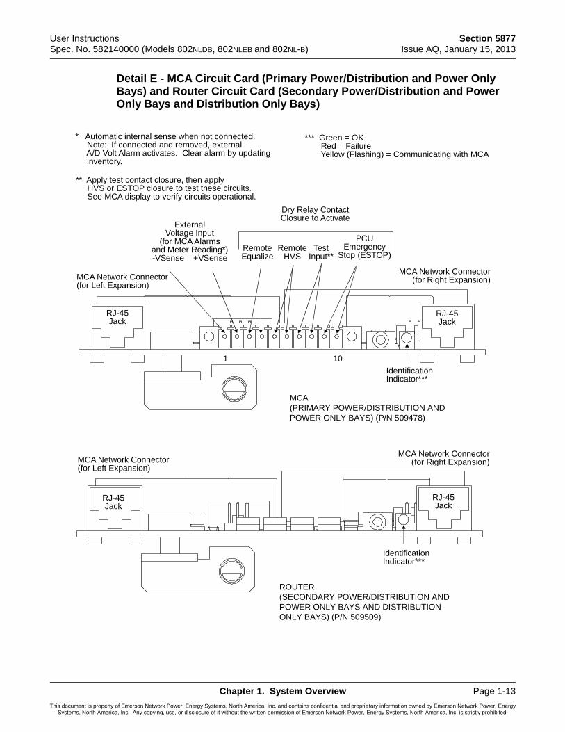
Detail E - MCA Circuit Card (Primary Power/Distribution and Power Only Bays) and Router Circuit Card (Secondary Power/Distribution and Power Only Bays and Distribution Only Bays)
MCA
(PRIMARY POWER/DISTRIBUTION AND
POWER ONLY BAYS) (P/N 509478)
ROUTER
(SECONDARY POWER/DISTRIBUTION AND
POWER ONLY BAYS AND DISTRIBUTION
ONLY BAYS) (P/N 509509)
RJ-45Jack
RJ-45Jack
RJ-45Jack
RJ-45Jack
MCA Network Connector(for Left Expansion)
MCA Network Connector(for Right Expansion)
IdentificationIndicator***
MCA Network Connector(for Left Expansion)
MCA Network Connector(for Right Expansion)
** Apply test contact closure, then applyHVS or ESTOP closure to test these circuits.See MCA display to verify circuits operational.
* Automatic internal sense when not connected.Note: If connected and removed, externalA/D Volt Alarm activates. Clear alarm by updatinginventory.
*** Green = OKRed = FailureYellow (Flashing) = Communicating with MCA
IdentificationIndicator***
RemoteEqualize
RemoteHVS
PCUEmergency
Stop (ESTOP)Test
Input**
Dry Relay ContactClosure to Activate
ExternalVoltage Input
(for MCA Alarmsand Meter Reading*)-VSense +VSense
1 10
Section 5877 User Instructions Issue AQ, January 15, 2013 Spec. No. 582140000 (Models 802NLDB, 802NLEB and 802NL-B)
Page 1-14 Chapter 1. System Overview
This document is property of Emerson Network Power, Energy Systems, North America, Inc. and contains confidential and proprietary information owned by Emerson Network Power, Energy Systems, North America, Inc. Any copying, use, or disclosure of it without the written permission of Emerson Network Power, Energy Systems, North America, Inc. is strictly prohibited.
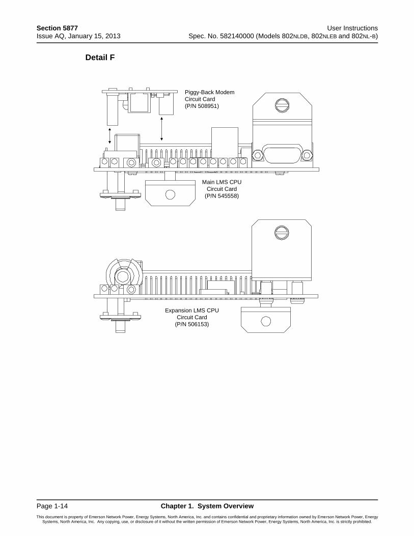
Detail F
Piggy-Back Modem
Circuit Card
(P/N 508951)
Main LMS CPU
Circuit Card
(P/N 545558)
Expansion LMS CPU
Circuit Card
(P/N 506153)
User Instructions Section 5877 Spec. No. 582140000 (Models 802NLDB, 802NLEB and 802NL-B) Issue AQ, January 15, 2013
Chapter 1. System Overview Page 1-15
This document is property of Emerson Network Power, Energy Systems, North America, Inc. and contains confidential and proprietary information owned by Emerson Network Power, Energy Systems, North America, Inc. Any copying, use, or disclosure of it without the written permission of Emerson Network Power, Energy Systems, North America, Inc. is strictly prohibited.
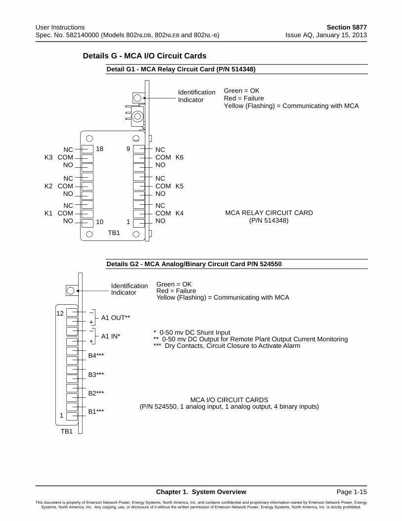
Details G - MCA I/O Circuit Cards
Detail G1 - MCA Relay Circuit Card (P/N 514348)
Details G2 - MCA Analog/Binary Circuit Card P/N 524550
MCA RELAY CIRCUIT CARD(P/N 514348)
IdentificationIndicator
Green = OKRed = FailureYellow (Flashing) = Communicating with MCA
1
9
10
18
K3
K2
K1
K6
K5
K4NCCOMNO
NCCOMNO
NCCOMNO
NCCOM
NO
NCCOM
NO
NCCOM
NO
TB1
MCA I/O CIRCUIT CARDS(P/N 524550, 1 analog input, 1 analog output, 4 binary inputs)
IdentificationIndicator
Green = OKRed = FailureYellow (Flashing) = Communicating with MCA
1
12
TB1
B1***
B2***
B3***
B4***
A1 IN*
A1 OUT**
+
_+
_
* 0-50 mv DC Shunt Input** 0-50 mv DC Output for Remote Plant Output Current Monitoring*** Dry Contacts, Circuit Closure to Activate Alarm
Section 5877 User Instructions Issue AQ, January 15, 2013 Spec. No. 582140000 (Models 802NLDB, 802NLEB and 802NL-B)
Page 1-16 Chapter 1. System Overview
This document is property of Emerson Network Power, Energy Systems, North America, Inc. and contains confidential and proprietary information owned by Emerson Network Power, Energy Systems, North America, Inc. Any copying, use, or disclosure of it without the written permission of Emerson Network Power, Energy Systems, North America, Inc. is strictly prohibited.
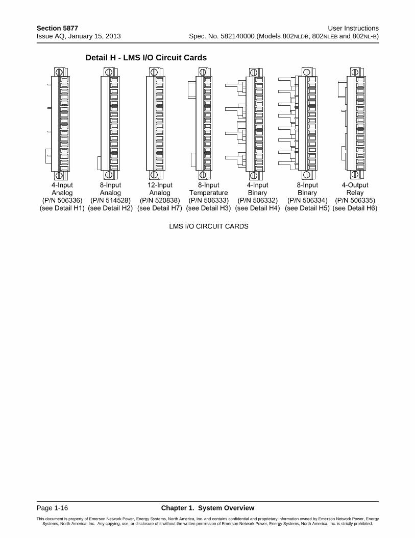
Detail H - LMS I/O Circuit Cards
User Instructions Section 5877 Spec. No. 582140000 (Models 802NLDB, 802NLEB and 802NL-B) Issue AQ, January 15, 2013
Chapter 1. System Overview Page 1-17
This document is property of Emerson Network Power, Energy Systems, North America, Inc. and contains confidential and proprietary information owned by Emerson Network Power, Energy Systems, North America, Inc. Any copying, use, or disclosure of it without the written permission of Emerson Network Power, Energy Systems, North America, Inc. is strictly prohibited.
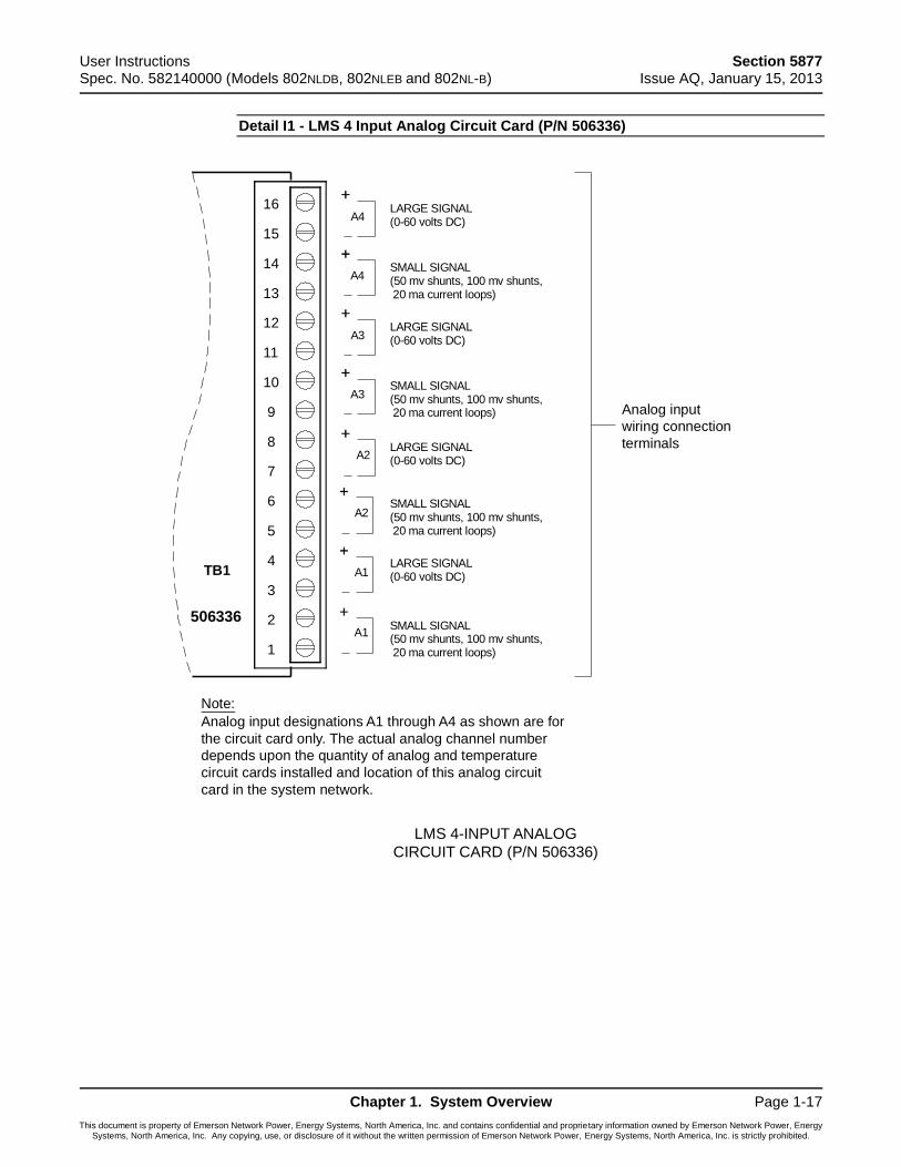
Detail I1 - LMS 4 Input Analog Circuit Card (P/N 506336)
LARGE SIGNAL(0-60 volts DC)
SMALL SIGNAL(50 mv shunts, 100 mv shunts,20 ma current loops)
LARGE SIGNAL(0-60 volts DC)
SMALL SIGNAL
LARGE SIGNAL(0-60 volts DC)
SMALL SIGNAL
LARGE SIGNAL(0-60 volts DC)
SMALL SIGNAL
Note:
LMS 4-INPUT ANALOG
CIRCUIT CARD (P/N 506336)
Analog input
wiring connection
terminals
Analog input designations A1 through A4 as shown are for
the circuit card only. The actual analog channel number
depends upon the quantity of analog and temperature
circuit cards installed and location of this analog circuit
card in the system network.
A4
A4
A3
A3
A2
A2
A1
A1
16
15
14
13
12
11
10
9
8
7
6
5
4
3
2
1
(50 mv shunts, 100 mv shunts,20 ma current loops)
(50 mv shunts, 100 mv shunts,20 ma current loops)
(50 mv shunts, 100 mv shunts,20 ma current loops)
TB1
506336
Section 5877 User Instructions Issue AQ, January 15, 2013 Spec. No. 582140000 (Models 802NLDB, 802NLEB and 802NL-B)
Page 1-18 Chapter 1. System Overview
This document is property of Emerson Network Power, Energy Systems, North America, Inc. and contains confidential and proprietary information owned by Emerson Network Power, Energy Systems, North America, Inc. Any copying, use, or disclosure of it without the written permission of Emerson Network Power, Energy Systems, North America, Inc. is strictly prohibited.
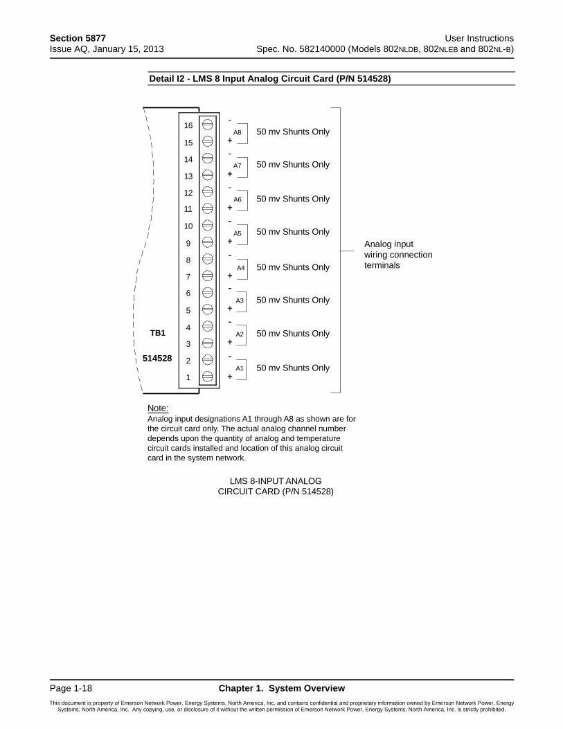
Detail I2 - LMS 8 Input Analog Circuit Card (P/N 514528)
16
15
14
13
12
11
10
9
8
7
6
5
4
3
2
1
A8
A7
A6
A5
A4
A3
A2
A1
50 mv Shunts Only
50 mv Shunts Only
50 mv Shunts Only
50 mv Shunts Only
50 mv Shunts Only
50 mv Shunts Only
50 mv Shunts Only
50 mv Shunts Only
Note:
LMS 8-INPUT ANALOGCIRCUIT CARD (P/N 514528)
Analog input designations A1 through A8 as shown are for
the circuit card only. The actual analog channel number
depends upon the quantity of analog and temperature
circuit cards installed and location of this analog circuit
card in the system network.
Analog input
wiring connection
terminals
TB1
514528
User Instructions Section 5877 Spec. No. 582140000 (Models 802NLDB, 802NLEB and 802NL-B) Issue AQ, January 15, 2013
Chapter 1. System Overview Page 1-19
This document is property of Emerson Network Power, Energy Systems, North America, Inc. and contains confidential and proprietary information owned by Emerson Network Power, Energy Systems, North America, Inc. Any copying, use, or disclosure of it without the written permission of Emerson Network Power, Energy Systems, North America, Inc. is strictly prohibited.
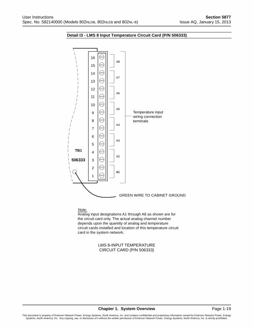
Detail I3 - LMS 8 Input Temperature Circuit Card (P/N 506333)
Temperature input
wiring connection
terminals
Note:
Analog input designations A1 through A8 as shown are for
the circuit card only. The actual analog channel number
depends upon the quantity of analog and temperature
circuit cards installed and location of this temperature circuit
card in the system network.
LMS 8-INPUT TEMPERATURE
CIRCUIT CARD (P/N 506333)
GREEN WIRE TO CABINET GROUND
16
15
14
13
12
11
10
9
8
7
6
5
4
3
2
1
A8
A7
A6
A5
A4
A3
A2
A1A1
TB1
506333
Section 5877 User Instructions Issue AQ, January 15, 2013 Spec. No. 582140000 (Models 802NLDB, 802NLEB and 802NL-B)
Page 1-20 Chapter 1. System Overview
This document is property of Emerson Network Power, Energy Systems, North America, Inc. and contains confidential and proprietary information owned by Emerson Network Power, Energy Systems, North America, Inc. Any copying, use, or disclosure of it without the written permission of Emerson Network Power, Energy Systems, North America, Inc. is strictly prohibited.
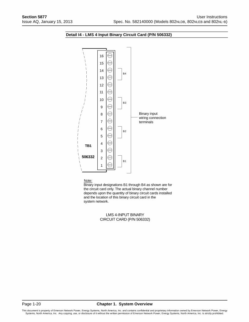
Detail I4 - LMS 4 Input Binary Circuit Card (P/N 506332)
Binary inputwiring connection
terminals
Note:Binary input designations B1 through B4 as shown are forthe circuit card only. The actual binary channel numberdepends upon the quantity of binary circuit cards installedand the location of this binary circuit card in thesystem network.
LMS 4-INPUT BINARYCIRCUIT CARD (P/N 506332)
16
15
14
13
12
11
10
9
8
7
6
5
4
3
2
1
B4
TB1
506332
B3
B2
B1
User Instructions Section 5877 Spec. No. 582140000 (Models 802NLDB, 802NLEB and 802NL-B) Issue AQ, January 15, 2013
Chapter 1. System Overview Page 1-21
This document is property of Emerson Network Power, Energy Systems, North America, Inc. and contains confidential and proprietary information owned by Emerson Network Power, Energy Systems, North America, Inc. Any copying, use, or disclosure of it without the written permission of Emerson Network Power, Energy Systems, North America, Inc. is strictly prohibited.
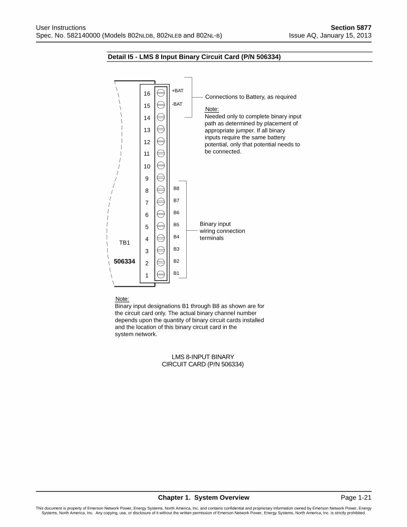
Detail I5 - LMS 8 Input Binary Circuit Card (P/N 506334)
Binary input
wiring connection
terminals
Note:
Binary input designations B1 through B8 as shown are for
the circuit card only. The actual binary channel number
depends upon the quantity of binary circuit cards installed
and the location of this binary circuit card in the
system network.
LMS 8-INPUT BINARYCIRCUIT CARD (P/N 506334)
16
15
14
13
12
11
10
9
8
7
6
5
4
3
2
1
B8
B7
B6
B5
B4
B3
B2
B1
Note:
Needed only to complete binary input
path as determined by placement of
appropriate jumper. If all binary
inputs require the same battery
potential, only that potential needs to
be connected.
Connections to Battery, as required
TB1
506334
+BAT
-BAT
Section 5877 User Instructions Issue AQ, January 15, 2013 Spec. No. 582140000 (Models 802NLDB, 802NLEB and 802NL-B)
Page 1-22 Chapter 1. System Overview
This document is property of Emerson Network Power, Energy Systems, North America, Inc. and contains confidential and proprietary information owned by Emerson Network Power, Energy Systems, North America, Inc. Any copying, use, or disclosure of it without the written permission of Emerson Network Power, Energy Systems, North America, Inc. is strictly prohibited.
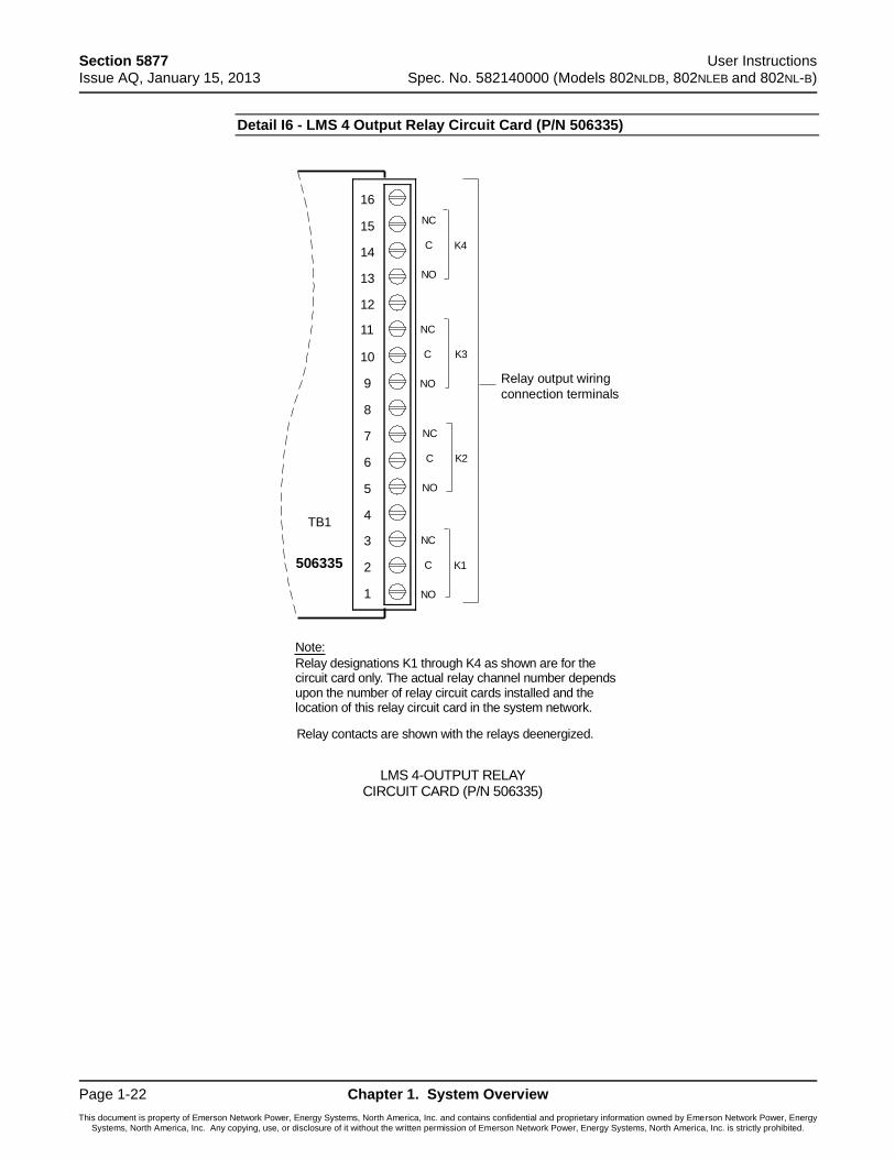
Detail I6 - LMS 4 Output Relay Circuit Card (P/N 506335)
Relay output wiring
connection terminals
Note:
Relay designations K1 through K4 as shown are for thecircuit card only. The actual relay channel number dependsupon the number of relay circuit cards installed and thelocation of this relay circuit card in the system network.
LMS 4-OUTPUT RELAYCIRCUIT CARD (P/N 506335)
16
15
14
13
12
11
10
9
8
7
6
5
4
3
2
1
NC
C
NO
TB1
506335
NC
C
NO
NC
C
NO
NC
C
NO
K4
K3
K2
K1
Relay contacts are shown with the relays deenergized.

User Instructions Section 5877 Spec. No. 582140000 (Models 802NLDB, 802NLEB and 802NL-B) Issue AQ, January 15, 2013
Chapter 1. System Overview Page 1-23
This document is property of Emerson Network Power, Energy Systems, North America, Inc. and contains confidential and proprietary information owned by Emerson Network Power, Energy Systems, North America, Inc. Any copying, use, or disclosure of it without the written permission of Emerson Network Power, Energy Systems, North America, Inc. is strictly prohibited.
Detail I7 - LMS 12 Input Analog Circuit Card (P/N 520838)
Analog input
wiring connection
terminals
Note:
Analog input designations A1 through A12 as shown are forthe circuit card only. The actual analog channel numberdepends upon the quantity of analog and temperaturecircuit cards installed and location of this analog circuit cardin the system network.
LMS 12-INPUT ANALOGCIRCUIT CARD (P/N 520838)
16
15
14
13
12
11
10
9
8
7
6
5
4
3
2
1
unused
unused
unused
TB1
520838
+ Terminal Battery Cell 12 (A12)
+ Terminal Battery Cell 11 (A11)
+ Terminal Battery Cell 10 (A10)
+ Terminal Battery Cell 9 (A9)
+ Terminal Battery Cell 8 (A8)
+ Terminal Battery Cell 7 (A7)
+ Terminal Battery Cell 6 (A6)
+ Terminal Battery Cell 5 (A5)
+ Terminal Battery Cell 4 (A4)
+ Terminal Battery Cell 3 (A3)
+ Terminal Battery Cell 2 (A2)
+ Terminal Battery Cell 1 (A1)
-- Terminal Battery Cell 11
Section 5877 User Instructions Issue AQ, January 15, 2013 Spec. No. 582140000 (Models 802NLDB, 802NLEB and 802NL-B)
Page 1-24 Chapter 1. System Overview
This document is property of Emerson Network Power, Energy Systems, North America, Inc. and contains confidential and proprietary information owned by Emerson Network Power, Energy Systems, North America, Inc. Any copying, use, or disclosure of it without the written permission of Emerson Network Power, Energy Systems, North America, Inc. is strictly prohibited.
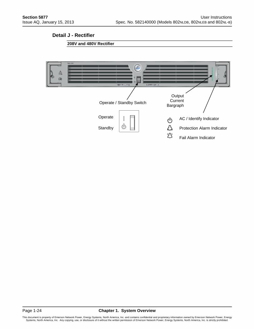
Detail J - Rectifier
208V and 480V Rectifier
AC / Identify Indicator Protection Alarm Indicator Fail Alarm Indicator
Output Current
Bargraph
Operate
Standby
Operate / Standby Switch
User Instructions Section 5877 Spec. No. 582140000 (Models 802NLDB, 802NLEB and 802NL-B) Issue AQ, January 15, 2013
Chapter 2. Navigating the MCA Page 2-1
This document is property of Emerson Network Power, Energy Systems, North America, Inc. and contains confidential and proprietary information owned by Emerson Network Power, Energy Systems, North America, Inc. Any copying, use, or disclosure of it without the written permission of Emerson Network Power, Energy Systems, North America, Inc. is strictly prohibited.
CHAPTER 2 0BNAVIGATING THE MCA
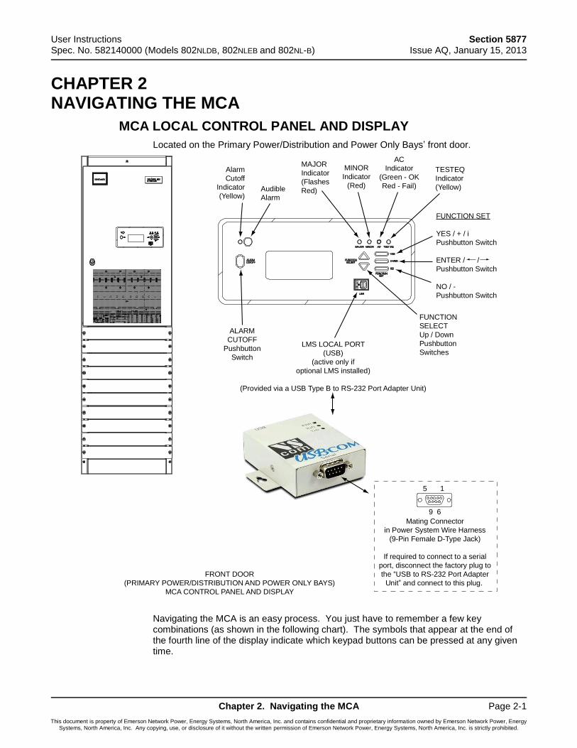
1BMCA LOCAL CONTROL PANEL AND DISPLAY
Located on the Primary Power/Distribution and Power Only Bays’ front door.
Navigating the MCA is an easy process. You just have to remember a few key combinations (as shown in the following chart). The symbols that appear at the end of the fourth line of the display indicate which keypad buttons can be pressed at any given time.
Alarm
Cutoff
Indicator
(Yellow)
FUNCTION SET
YES / + / i
Pushbutton Switch
ENTER / /
Pushbutton Switch
NO / -
Pushbutton Switch
ALARM
CUTOFF
Pushbutton
Switch
FUNCTION
SELECT
Up / Down
Pushbutton
Switches
TESTEQ
Indicator
(Yellow)
AC
Indicator
(Green - OK
Red - Fail)
MINOR
Indicator
(Red)
MAJOR
Indicator
(Flashes
Red)Audible
Alarm
FRONT DOOR
(PRIMARY POWER/DISTRIBUTION AND POWER ONLY BAYS)
MCA CONTROL PANEL AND DISPLAY
LMS LOCAL PORT
(USB)
(active only if
optional LMS installed)
(Provided via a USB Type B to RS-232 Port Adapter Unit)
15
9 6
Mating Connector
in Power System Wire Harness
(9-Pin Female D-Type Jack)
If required to connect to a serial
port, disconnect the factory plug to
the “USB to RS-232 Port Adapter
Unit” and connect to this plug.
Section 5877 User Instructions Issue AQ, January 15, 2013 Spec. No. 582140000 (Models 802NLDB, 802NLEB and 802NL-B)
Page 2-2 Chapter 2. Navigating the MCA
This document is property of Emerson Network Power, Energy Systems, North America, Inc. and contains confidential and proprietary information owned by Emerson Network Power, Energy Systems, North America, Inc. Any copying, use, or disclosure of it without the written permission of Emerson Network Power, Energy Systems, North America, Inc. is strictly prohibited.
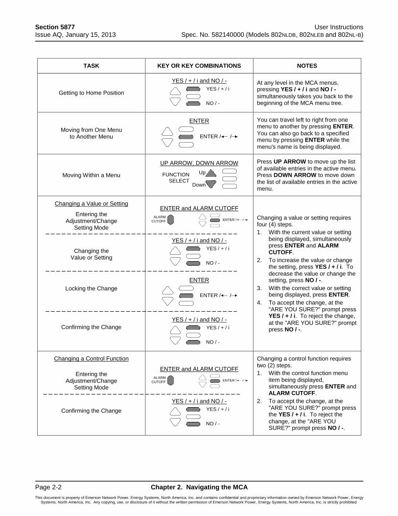
TASK KEY OR KEY COMBINATIONS NOTES
Getting to Home Position
UYES / + / i and NO / -
At any level in the MCA menus, pressing YES / + / i and NO / -
simultaneously takes you back to the beginning of the MCA menu tree.
Moving from One Menu to Another Menu
UENTER
You can travel left to right from one menu to another by pressing ENTER.
You can also go back to a specified menu by pressing ENTER while the
menu's name is being displayed.
Moving Within a Menu
UUP ARROW, DOWN ARROW
Press UP ARROW to move up the list
of available entries in the active menu. Press DOWN ARROW to move down
the list of available entries in the active menu.
UChanging a Value or Setting
Entering the Adjustment/Change
Setting Mode
Changing the Value or Setting
Locking the Change
Confirming the Change
UENTER and ALARM CUTOFF
UYES / + / i and NO / -
UENTER
UYES / + / i and NO / -
Changing a value or setting requires four (4) steps.
1. With the current value or setting being displayed, simultaneously press ENTER and ALARM CUTOFF.
2. To increase the value or change the setting, press YES / + / i. To
decrease the value or change the setting, press NO / -.
3. With the correct value or setting being displayed, press ENTER.
4. To accept the change, at the "ARE YOU SURE?" prompt press YES / + / i. To reject the change,
at the "ARE YOU SURE?" prompt press NO / -.
UChanging a Control Function
Entering the Adjustment/Change
Setting Mode
Confirming the Change
UENTER and ALARM CUTOFF
UYES / + / i and NO / -
Changing a control function requires two (2) steps.
1. With the control function menu item being displayed, simultaneously press ENTER and ALARM CUTOFF.
2. To accept the change, at the "ARE YOU SURE?" prompt press the YES / + / i. To reject the
change, at the "ARE YOU SURE?" prompt press NO / -.
YES / + / i
NO / -
ENTER / /
Up
Down
FUNCTION
SELECT
ALARM
CUTOFF ENTER / /
YES / + / i
NO / -
ENTER / /
YES / + / i
NO / -
ALARM
CUTOFF ENTER / /
YES / + / i
NO / -
User Instructions Section 5877 Spec. No. 582140000 (Models 802NLDB, 802NLEB and 802NL-B) Issue AQ, January 15, 2013
Chapter 2. Navigating the MCA Page 2-3
This document is property of Emerson Network Power, Energy Systems, North America, Inc. and contains confidential and proprietary information owned by Emerson Network Power, Energy Systems, North America, Inc. Any copying, use, or disclosure of it without the written permission of Emerson Network Power, Energy Systems, North America, Inc. is strictly prohibited.
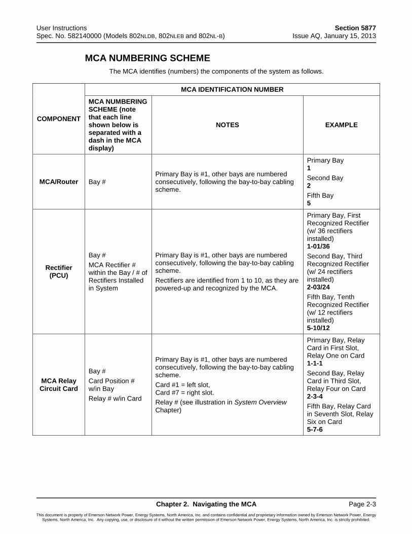
2BMCA NUMBERING SCHEME
The MCA identifies (numbers) the components of the system as follows.
COMPONENT
MCA IDENTIFICATION NUMBER
MCA NUMBERING SCHEME (note that each line shown below is separated with a dash in the MCA display)
NOTES EXAMPLE
MCA/Router Bay # Primary Bay is #1, other bays are numbered consecutively, following the bay-to-bay cabling scheme.
Primary Bay 1
Second Bay 2
Fifth Bay 5
Rectifier (PCU)
Bay #
MCA Rectifier # within the Bay / # of Rectifiers Installed in System
Primary Bay is #1, other bays are numbered consecutively, following the bay-to-bay cabling scheme.
Rectifiers are identified from 1 to 10, as they are powered-up and recognized by the MCA.
Primary Bay, First Recognized Rectifier (w/ 36 rectifiers installed) 1-01/36
Second Bay, Third Recognized Rectifier (w/ 24 rectifiers installed) 2-03/24
Fifth Bay, Tenth Recognized Rectifier (w/ 12 rectifiers installed) 5-10/12
MCA Relay Circuit Card
Bay #
Card Position # w/in Bay
Relay # w/in Card
Primary Bay is #1, other bays are numbered consecutively, following the bay-to-bay cabling scheme.
Card #1 = left slot, Card #7 = right slot.
Relay # (see illustration in System Overview Chapter)
Primary Bay, Relay Card in First Slot, Relay One on Card 1-1-1
Second Bay, Relay Card in Third Slot, Relay Four on Card 2-3-4
Fifth Bay, Relay Card in Seventh Slot, Relay Six on Card 5-7-6
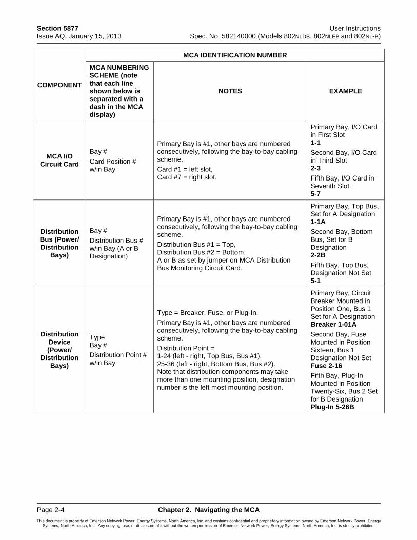
Section 5877 User Instructions Issue AQ, January 15, 2013 Spec. No. 582140000 (Models 802NLDB, 802NLEB and 802NL-B)
Page 2-4 Chapter 2. Navigating the MCA
This document is property of Emerson Network Power, Energy Systems, North America, Inc. and contains confidential and proprietary information owned by Emerson Network Power, Energy Systems, North America, Inc. Any copying, use, or disclosure of it without the written permission of Emerson Network Power, Energy Systems, North America, Inc. is strictly prohibited.
COMPONENT
MCA IDENTIFICATION NUMBER
MCA NUMBERING SCHEME (note that each line shown below is separated with a dash in the MCA display)
NOTES EXAMPLE
MCA I/O Circuit Card
Bay #
Card Position # w/in Bay
Primary Bay is #1, other bays are numbered consecutively, following the bay-to-bay cabling scheme.
Card #1 = left slot, Card #7 = right slot.
Primary Bay, I/O Card in First Slot 1-1
Second Bay, I/O Card in Third Slot 2-3
Fifth Bay, I/O Card in Seventh Slot 5-7
Distribution Bus (Power/ Distribution
Bays)
Bay #
Distribution Bus # w/in Bay (A or B Designation)
Primary Bay is #1, other bays are numbered consecutively, following the bay-to-bay cabling scheme.
Distribution Bus #1 = Top, Distribution Bus #2 = Bottom. A or B as set by jumper on MCA Distribution Bus Monitoring Circuit Card.
Primary Bay, Top Bus, Set for A Designation 1-1A
Second Bay, Bottom Bus, Set for B Designation 2-2B
Fifth Bay, Top Bus, Designation Not Set 5-1
Distribution Device (Power/
Distribution Bays)
Type Bay #
Distribution Point # w/in Bay
Type = Breaker, Fuse, or Plug-In.
Primary Bay is #1, other bays are numbered consecutively, following the bay-to-bay cabling scheme.
Distribution Point = 1-24 (left - right, Top Bus, Bus #1). 25-36 (left - right, Bottom Bus, Bus #2). Note that distribution components may take more than one mounting position, designation number is the left most mounting position.
Primary Bay, Circuit Breaker Mounted in Position One, Bus 1 Set for A Designation Breaker 1-01A
Second Bay, Fuse Mounted in Position Sixteen, Bus 1 Designation Not Set Fuse 2-16
Fifth Bay, Plug-In Mounted in Position Twenty-Six, Bus 2 Set for B Designation Plug-In 5-26B
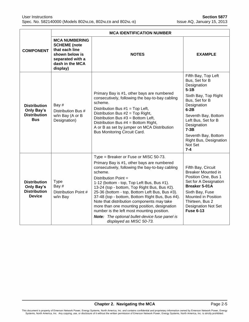
User Instructions Section 5877 Spec. No. 582140000 (Models 802NLDB, 802NLEB and 802NL-B) Issue AQ, January 15, 2013
Chapter 2. Navigating the MCA Page 2-5
This document is property of Emerson Network Power, Energy Systems, North America, Inc. and contains confidential and proprietary information owned by Emerson Network Power, Energy Systems, North America, Inc. Any copying, use, or disclosure of it without the written permission of Emerson Network Power, Energy Systems, North America, Inc. is strictly prohibited.
COMPONENT
MCA IDENTIFICATION NUMBER
MCA NUMBERING SCHEME (note that each line shown below is separated with a dash in the MCA display)
NOTES EXAMPLE
Distribution Only Bay’s Distribution
Bus
Bay #
Distribution Bus # w/in Bay (A or B Designation)
Primary Bay is #1, other bays are numbered consecutively, following the bay-to-bay cabling scheme.
Distribution Bus #1 = Top Left, Distribution Bus #2 = Top Right, Distribution Bus #3 = Bottom Left, Distribution Bus #4 = Bottom Right, A or B as set by jumper on MCA Distribution Bus Monitoring Circuit Card.
Fifth Bay, Top Left Bus, Set for B Designation 5-1B
Sixth Bay, Top Right Bus, Set for B Designation 6-2B
Seventh Bay, Bottom Left Bus, Set for B Designation 7-3B
Seventh Bay, Bottom Right Bus, Designation Not Set 7-4
Distribution Only Bay’s Distribution
Device
Type Bay #
Distribution Point # w/in Bay
Type = Breaker or Fuse or MISC 50-73.
Primary Bay is #1, other bays are numbered consecutively, following the bay-to-bay cabling scheme.
Distribution Point = 1-12 (bottom - top, Top Left Bus, Bus #1). 13-24 (top - bottom, Top Right Bus, Bus #2). 25-36 (bottom - top, Bottom Left Bus, Bus #3). 37-48 (top - bottom, Bottom Right Bus, Bus #4). Note that distribution components may take more than one mounting position, designation number is the left most mounting position.
Note: The optional bullet-device fuse panel is displayed as MISC 50-73.
Fifth Bay, Circuit Breaker Mounted in Position One, Bus 1 Set for A Designation Breaker 5-01A
Sixth Bay, Fuse Mounted in Position Thirteen, Bus 2 Designation Not Set Fuse 6-13
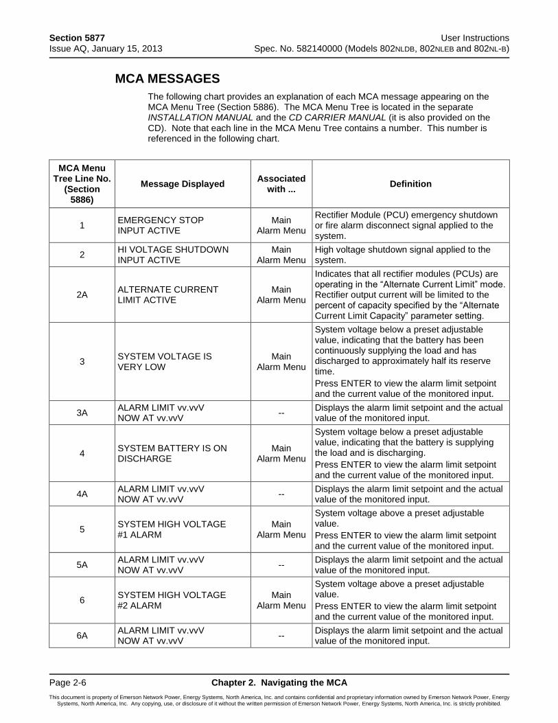
Section 5877 User Instructions Issue AQ, January 15, 2013 Spec. No. 582140000 (Models 802NLDB, 802NLEB and 802NL-B)
Page 2-6 Chapter 2. Navigating the MCA
This document is property of Emerson Network Power, Energy Systems, North America, Inc. and contains confidential and proprietary information owned by Emerson Network Power, Energy Systems, North America, Inc. Any copying, use, or disclosure of it without the written permission of Emerson Network Power, Energy Systems, North America, Inc. is strictly prohibited.
3BMCA MESSAGES
The following chart provides an explanation of each MCA message appearing on the MCA Menu Tree (Section 5886). The MCA Menu Tree is located in the separate INSTALLATION MANUAL and the CD CARRIER MANUAL (it is also provided on the CD). Note that each line in the MCA Menu Tree contains a number. This number is referenced in the following chart.
MCA Menu Tree Line No.
(Section 5886)
Message Displayed Associated
with ... Definition
1 EMERGENCY STOP INPUT ACTIVE
Main Alarm Menu
Rectifier Module (PCU) emergency shutdown or fire alarm disconnect signal applied to the system.
2 HI VOLTAGE SHUTDOWN INPUT ACTIVE
Main Alarm Menu
High voltage shutdown signal applied to the system.
2A ALTERNATE CURRENT LIMIT ACTIVE
Main Alarm Menu
Indicates that all rectifier modules (PCUs) are operating in the “Alternate Current Limit” mode. Rectifier output current will be limited to the percent of capacity specified by the “Alternate Current Limit Capacity” parameter setting.
3 SYSTEM VOLTAGE IS VERY LOW
Main Alarm Menu
System voltage below a preset adjustable value, indicating that the battery has been continuously supplying the load and has discharged to approximately half its reserve time.
Press ENTER to view the alarm limit setpoint and the current value of the monitored input.
3A ALARM LIMIT vv.vvV NOW AT vv.vvV
-- Displays the alarm limit setpoint and the actual value of the monitored input.
4 SYSTEM BATTERY IS ON DISCHARGE
Main Alarm Menu
System voltage below a preset adjustable value, indicating that the battery is supplying the load and is discharging.
Press ENTER to view the alarm limit setpoint and the current value of the monitored input.
4A ALARM LIMIT vv.vvV NOW AT vv.vvV
-- Displays the alarm limit setpoint and the actual value of the monitored input.
5 SYSTEM HIGH VOLTAGE #1 ALARM
Main Alarm Menu
System voltage above a preset adjustable value.
Press ENTER to view the alarm limit setpoint and the current value of the monitored input.
5A ALARM LIMIT vv.vvV NOW AT vv.vvV
-- Displays the alarm limit setpoint and the actual value of the monitored input.
6 SYSTEM HIGH VOLTAGE #2 ALARM
Main Alarm Menu
System voltage above a preset adjustable value.
Press ENTER to view the alarm limit setpoint and the current value of the monitored input.
6A ALARM LIMIT vv.vvV NOW AT vv.vvV
-- Displays the alarm limit setpoint and the actual value of the monitored input.

User Instructions Section 5877 Spec. No. 582140000 (Models 802NLDB, 802NLEB and 802NL-B) Issue AQ, January 15, 2013
Chapter 2. Navigating the MCA Page 2-7
This document is property of Emerson Network Power, Energy Systems, North America, Inc. and contains confidential and proprietary information owned by Emerson Network Power, Energy Systems, North America, Inc. Any copying, use, or disclosure of it without the written permission of Emerson Network Power, Energy Systems, North America, Inc. is strictly prohibited.
MCA Menu Tree Line No.
(Section 5886)
Message Displayed Associated
with ... Definition
7
1 SYSTEM BREAKER OR FUSE ALARM or ### SYSTEM BREAKER & FUSE ALARMS
Main Alarm Menu
One or more system fuses or circuit breakers open. (### = number of open system fuses or circuit breakers.)
Press ENTER to view which fuse(s) or circuit breaker(s) is open.
Note that the individual fuses and circuit breakers in the bullet nose-type device holders (plug-in) are not counted. If any number within a bullet nose-type device holder (plug-in) are open, only one will be counted.
8 F/CB/PI B#-P#A/B IS OPEN
Fuse Alarm Menu
Identification of open system fuse or circuit breaker. (F/CB/PI B#-P#A/B = Fuse or Circuit Breaker or PlugIn, Bay Number-Distribution Device Position Number [Group A or B Designation if applicable.])
Press UP and DOWN ARROWS to scroll if multiple distribution devices are open.
9 GO TO MAIN ALARM MENU
Fuse Alarm Menu
Press ENTER to go to this menu.
10 GO BACK TO MENU TREE BEGINNING
Fuse Alarm Menu
Press ENTER to go to the beginning of the MCA Menu Tree.
11 AC POWER IS OFF TO ALL PCUs
Main Alarm Menu
AC input voltage to all Rectifier Modules (PCUs) below a preset non-adjustable value.
12
1 PCU HAS FAILED or ### PCUs HAVE FAILED or NO PCUs ARE IN INVENTORY
Main Alarm Menu
One or more Rectifier Modules (PCUs) failed. (### = number of failed Rectifier Modules [PCUs].)
Press ENTER to view which Rectifier Module (PCU) failed.
or
If the MCA does not recognize any Rectifier Module (PCU), NO PCUs ARE IN INVENTORY is displayed.
13 PCU B#-ID#/N# FAILURE
PCU Alarm Menu
Identification of failed Rectifier Module (PCU). (B#-ID#/N# = Bay Number-Rectifier Module MCA ID# w/in Bay/Number of Rectifier Modules in System.)
Press UP and DOWN ARROWS to scroll if multiple Rectifier Modules failed.
Press ENTER to view why Rectifier Module failed.
14 ### REMOTE PCUS HAVE FAILED
PCU Alarm Menu
More than one Remote Rectifier (PCU) failed. (### = number of failed Remote Rectifiers [PCUs].)
15 1 REMOTE PCU HAS FAILED
PCU Alarm Menu
One Remote Rectifier (PCU) failed.
16 GO TO MAIN ALARM MENU
PCU Alarm Menu
Press ENTER to go to this menu.
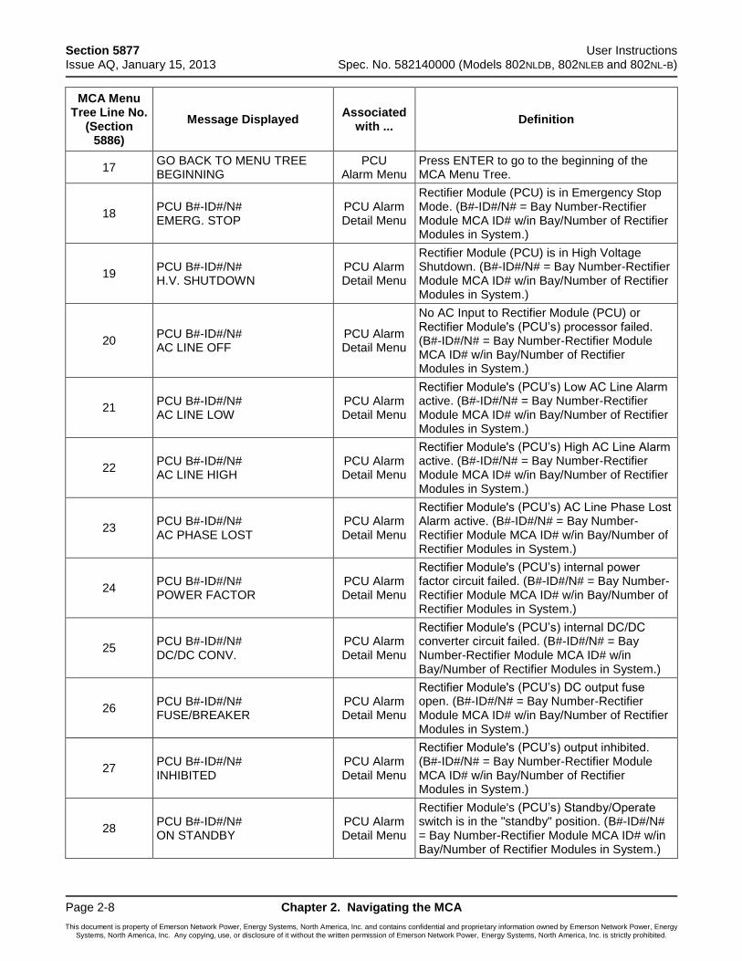
Section 5877 User Instructions Issue AQ, January 15, 2013 Spec. No. 582140000 (Models 802NLDB, 802NLEB and 802NL-B)
Page 2-8 Chapter 2. Navigating the MCA
This document is property of Emerson Network Power, Energy Systems, North America, Inc. and contains confidential and proprietary information owned by Emerson Network Power, Energy Systems, North America, Inc. Any copying, use, or disclosure of it without the written permission of Emerson Network Power, Energy Systems, North America, Inc. is strictly prohibited.
MCA Menu Tree Line No.
(Section 5886)
Message Displayed Associated
with ... Definition
17 GO BACK TO MENU TREE BEGINNING
PCU Alarm Menu
Press ENTER to go to the beginning of the MCA Menu Tree.
18 PCU B#-ID#/N# EMERG. STOP
PCU Alarm Detail Menu
Rectifier Module (PCU) is in Emergency Stop Mode. (B#-ID#/N# = Bay Number-Rectifier Module MCA ID# w/in Bay/Number of Rectifier Modules in System.)
19 PCU B#-ID#/N# H.V. SHUTDOWN
PCU Alarm Detail Menu
Rectifier Module (PCU) is in High Voltage Shutdown. (B#-ID#/N# = Bay Number-Rectifier Module MCA ID# w/in Bay/Number of Rectifier Modules in System.)
20 PCU B#-ID#/N# AC LINE OFF
PCU Alarm Detail Menu
No AC Input to Rectifier Module (PCU) or Rectifier Module's (PCU’s) processor failed. (B#-ID#/N# = Bay Number-Rectifier Module MCA ID# w/in Bay/Number of Rectifier Modules in System.)
21 PCU B#-ID#/N# AC LINE LOW
PCU Alarm Detail Menu
Rectifier Module's (PCU’s) Low AC Line Alarm active. (B#-ID#/N# = Bay Number-Rectifier Module MCA ID# w/in Bay/Number of Rectifier Modules in System.)
22 PCU B#-ID#/N# AC LINE HIGH
PCU Alarm Detail Menu
Rectifier Module's (PCU’s) High AC Line Alarm active. (B#-ID#/N# = Bay Number-Rectifier Module MCA ID# w/in Bay/Number of Rectifier Modules in System.)
23 PCU B#-ID#/N# AC PHASE LOST
PCU Alarm Detail Menu
Rectifier Module's (PCU’s) AC Line Phase Lost Alarm active. (B#-ID#/N# = Bay Number-Rectifier Module MCA ID# w/in Bay/Number of Rectifier Modules in System.)
24 PCU B#-ID#/N# POWER FACTOR
PCU Alarm Detail Menu
Rectifier Module's (PCU’s) internal power factor circuit failed. (B#-ID#/N# = Bay Number-Rectifier Module MCA ID# w/in Bay/Number of Rectifier Modules in System.)
25 PCU B#-ID#/N# DC/DC CONV.
PCU Alarm Detail Menu
Rectifier Module's (PCU’s) internal DC/DC converter circuit failed. (B#-ID#/N# = Bay Number-Rectifier Module MCA ID# w/in Bay/Number of Rectifier Modules in System.)
26 PCU B#-ID#/N# FUSE/BREAKER
PCU Alarm Detail Menu
Rectifier Module's (PCU’s) DC output fuse open. (B#-ID#/N# = Bay Number-Rectifier Module MCA ID# w/in Bay/Number of Rectifier Modules in System.)
27 PCU B#-ID#/N# INHIBITED
PCU Alarm Detail Menu
Rectifier Module's (PCU’s) output inhibited. (B#-ID#/N# = Bay Number-Rectifier Module MCA ID# w/in Bay/Number of Rectifier Modules in System.)
28 PCU B#-ID#/N# ON STANDBY
PCU Alarm Detail Menu
Rectifier Module's (PCU’s) Standby/Operate switch is in the "standby" position. (B#-ID#/N# = Bay Number-Rectifier Module MCA ID# w/in Bay/Number of Rectifier Modules in System.)
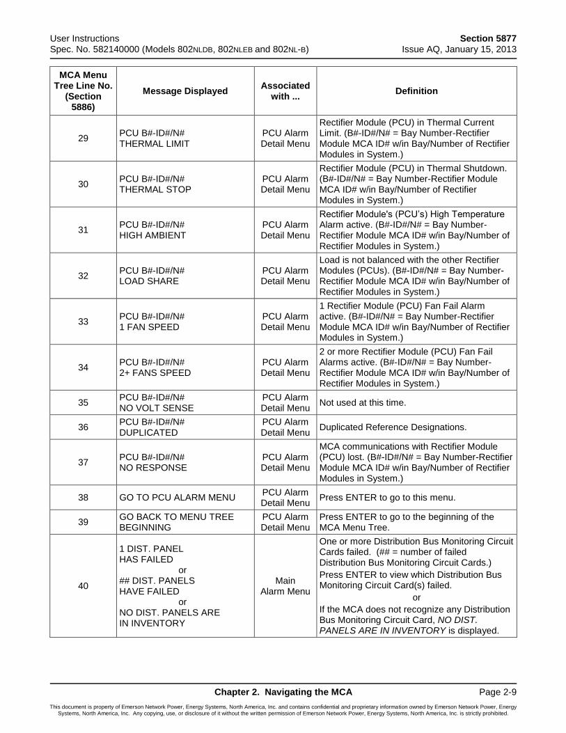
User Instructions Section 5877 Spec. No. 582140000 (Models 802NLDB, 802NLEB and 802NL-B) Issue AQ, January 15, 2013
Chapter 2. Navigating the MCA Page 2-9
This document is property of Emerson Network Power, Energy Systems, North America, Inc. and contains confidential and proprietary information owned by Emerson Network Power, Energy Systems, North America, Inc. Any copying, use, or disclosure of it without the written permission of Emerson Network Power, Energy Systems, North America, Inc. is strictly prohibited.
MCA Menu Tree Line No.
(Section 5886)
Message Displayed Associated
with ... Definition
29 PCU B#-ID#/N# THERMAL LIMIT
PCU Alarm Detail Menu
Rectifier Module (PCU) in Thermal Current Limit. (B#-ID#/N# = Bay Number-Rectifier Module MCA ID# w/in Bay/Number of Rectifier Modules in System.)
30 PCU B#-ID#/N# THERMAL STOP
PCU Alarm Detail Menu
Rectifier Module (PCU) in Thermal Shutdown. (B#-ID#/N# = Bay Number-Rectifier Module MCA ID# w/in Bay/Number of Rectifier Modules in System.)
31 PCU B#-ID#/N# HIGH AMBIENT
PCU Alarm Detail Menu
Rectifier Module's (PCU’s) High Temperature Alarm active. (B#-ID#/N# = Bay Number-Rectifier Module MCA ID# w/in Bay/Number of Rectifier Modules in System.)
32 PCU B#-ID#/N# LOAD SHARE
PCU Alarm Detail Menu
Load is not balanced with the other Rectifier Modules (PCUs). (B#-ID#/N# = Bay Number-Rectifier Module MCA ID# w/in Bay/Number of Rectifier Modules in System.)
33 PCU B#-ID#/N# 1 FAN SPEED
PCU Alarm Detail Menu
1 Rectifier Module (PCU) Fan Fail Alarm active. (B#-ID#/N# = Bay Number-Rectifier Module MCA ID# w/in Bay/Number of Rectifier Modules in System.)
34 PCU B#-ID#/N# 2+ FANS SPEED
PCU Alarm Detail Menu
2 or more Rectifier Module (PCU) Fan Fail Alarms active. (B#-ID#/N# = Bay Number-Rectifier Module MCA ID# w/in Bay/Number of Rectifier Modules in System.)
35 PCU B#-ID#/N# NO VOLT SENSE
PCU Alarm Detail Menu
Not used at this time.
36 PCU B#-ID#/N# DUPLICATED
PCU Alarm Detail Menu
Duplicated Reference Designations.
37 PCU B#-ID#/N# NO RESPONSE
PCU Alarm Detail Menu
MCA communications with Rectifier Module (PCU) lost. (B#-ID#/N# = Bay Number-Rectifier Module MCA ID# w/in Bay/Number of Rectifier Modules in System.)
38 GO TO PCU ALARM MENU PCU Alarm Detail Menu
Press ENTER to go to this menu.
39 GO BACK TO MENU TREE BEGINNING
PCU Alarm Detail Menu
Press ENTER to go to the beginning of the MCA Menu Tree.
40
1 DIST. PANEL HAS FAILED or ## DIST. PANELS HAVE FAILED or NO DIST. PANELS ARE IN INVENTORY
Main Alarm Menu
One or more Distribution Bus Monitoring Circuit Cards failed. (## = number of failed Distribution Bus Monitoring Circuit Cards.)
Press ENTER to view which Distribution Bus Monitoring Circuit Card(s) failed.
or
If the MCA does not recognize any Distribution Bus Monitoring Circuit Card, NO DIST. PANELS ARE IN INVENTORY is displayed.
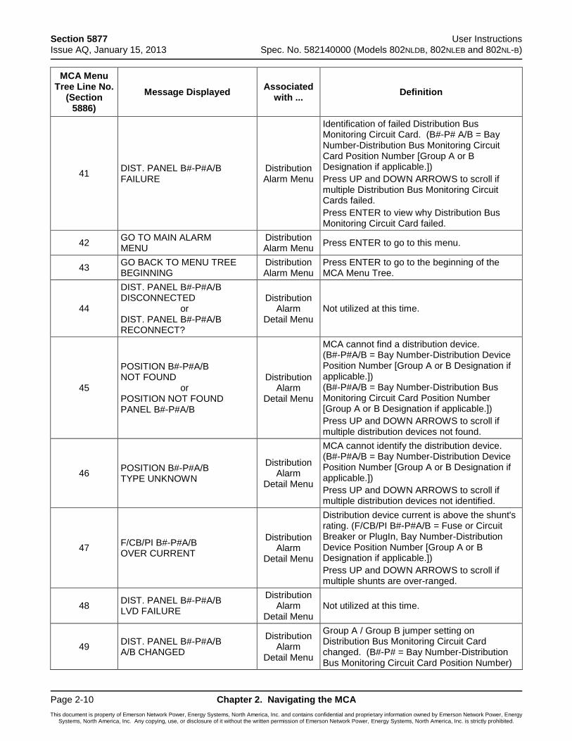
Section 5877 User Instructions Issue AQ, January 15, 2013 Spec. No. 582140000 (Models 802NLDB, 802NLEB and 802NL-B)
Page 2-10 Chapter 2. Navigating the MCA
This document is property of Emerson Network Power, Energy Systems, North America, Inc. and contains confidential and proprietary information owned by Emerson Network Power, Energy Systems, North America, Inc. Any copying, use, or disclosure of it without the written permission of Emerson Network Power, Energy Systems, North America, Inc. is strictly prohibited.
MCA Menu Tree Line No.
(Section 5886)
Message Displayed Associated
with ... Definition
41 DIST. PANEL B#-P#A/B FAILURE
Distribution Alarm Menu
Identification of failed Distribution Bus Monitoring Circuit Card. (B#-P# A/B = Bay Number-Distribution Bus Monitoring Circuit Card Position Number [Group A or B Designation if applicable.])
Press UP and DOWN ARROWS to scroll if multiple Distribution Bus Monitoring Circuit Cards failed.
Press ENTER to view why Distribution Bus Monitoring Circuit Card failed.
42 GO TO MAIN ALARM MENU
Distribution Alarm Menu
Press ENTER to go to this menu.
43 GO BACK TO MENU TREE BEGINNING
Distribution Alarm Menu
Press ENTER to go to the beginning of the MCA Menu Tree.
44
DIST. PANEL B#-P#A/B DISCONNECTED or DIST. PANEL B#-P#A/B RECONNECT?
Distribution Alarm
Detail Menu Not utilized at this time.
45
POSITION B#-P#A/B NOT FOUND or POSITION NOT FOUND PANEL B#-P#A/B
Distribution Alarm
Detail Menu
MCA cannot find a distribution device. (B#-P#A/B = Bay Number-Distribution Device Position Number [Group A or B Designation if applicable.]) (B#-P#A/B = Bay Number-Distribution Bus Monitoring Circuit Card Position Number [Group A or B Designation if applicable.])
Press UP and DOWN ARROWS to scroll if multiple distribution devices not found.
46 POSITION B#-P#A/B TYPE UNKNOWN
Distribution Alarm
Detail Menu
MCA cannot identify the distribution device. (B#-P#A/B = Bay Number-Distribution Device Position Number [Group A or B Designation if applicable.])
Press UP and DOWN ARROWS to scroll if multiple distribution devices not identified.
47 F/CB/PI B#-P#A/B OVER CURRENT
Distribution Alarm
Detail Menu
Distribution device current is above the shunt's rating. (F/CB/PI B#-P#A/B = Fuse or Circuit Breaker or PlugIn, Bay Number-Distribution Device Position Number [Group A or B Designation if applicable.])
Press UP and DOWN ARROWS to scroll if multiple shunts are over-ranged.
48 DIST. PANEL B#-P#A/B LVD FAILURE
Distribution Alarm
Detail Menu Not utilized at this time.
49 DIST. PANEL B#-P#A/B A/B CHANGED
Distribution Alarm
Detail Menu
Group A / Group B jumper setting on Distribution Bus Monitoring Circuit Card changed. (B#-P# = Bay Number-Distribution Bus Monitoring Circuit Card Position Number)
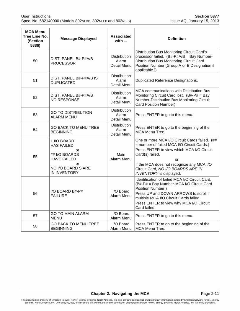
User Instructions Section 5877 Spec. No. 582140000 (Models 802NLDB, 802NLEB and 802NL-B) Issue AQ, January 15, 2013
Chapter 2. Navigating the MCA Page 2-11
This document is property of Emerson Network Power, Energy Systems, North America, Inc. and contains confidential and proprietary information owned by Emerson Network Power, Energy Systems, North America, Inc. Any copying, use, or disclosure of it without the written permission of Emerson Network Power, Energy Systems, North America, Inc. is strictly prohibited.
MCA Menu Tree Line No.
(Section 5886)
Message Displayed Associated
with ... Definition
50 DIST. PANEL B#-P#A/B PROCESSOR
Distribution Alarm
Detail Menu
Distribution Bus Monitoring Circuit Card's processor failed. (B#-P#A/B = Bay Number-Distribution Bus Monitoring Circuit Card Position Number [Group A or B Designation if applicable.])
51 DIST. PANEL B#-P#A/B IS DUPLICATED
Distribution Alarm
Detail Menu Duplicated Reference Designations.
52 DIST. PANEL B#-P#A/B NO RESPONSE
Distribution Alarm
Detail Menu
MCA communications with Distribution Bus Monitoring Circuit Card lost. (B#-P# = Bay Number-Distribution Bus Monitoring Circuit Card Position Number)
53 GO TO DISTRIBUTION ALARM MENU
Distribution Alarm
Detail Menu Press ENTER to go to this menu.
54 GO BACK TO MENU TREE BEGINNING
Distribution Alarm
Detail Menu
Press ENTER to go to the beginning of the MCA Menu Tree.
55
1 I/O BOARD HAS FAILED or ## I/O BOARDS HAVE FAILED or NO I/O BOARD S ARE IN INVENTORY
Main Alarm Menu
One or more MCA I/O Circuit Cards failed. (## = number of failed MCA I/O Circuit Cards.)
Press ENTER to view which MCA I/O Circuit Card(s) failed.
or
If the MCA does not recognize any MCA I/O Circuit Card, NO I/O BOARDS ARE IN INVENTORY is displayed.
56 I/O BOARD B#-P# FAILURE
I/O Board Alarm Menu
Identification of failed MCA I/O Circuit Card. (B#-P# = Bay Number-MCA I/O Circuit Card Position Number.)
Press UP and DOWN ARROWS to scroll if multiple MCA I/O Circuit Cards failed.
Press ENTER to view why MCA I/O Circuit Card failed.
57 GO TO MAIN ALARM MENU
I/O Board Alarm Menu
Press ENTER to go to this menu.
58 GO BACK TO MENU TREE BEGINNING
I/O Board Alarm Menu
Press ENTER to go to the beginning of the MCA Menu Tree.
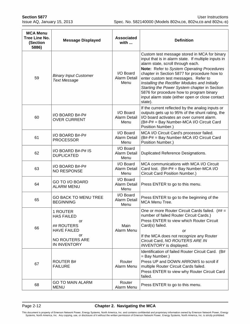
Section 5877 User Instructions Issue AQ, January 15, 2013 Spec. No. 582140000 (Models 802NLDB, 802NLEB and 802NL-B)
Page 2-12 Chapter 2. Navigating the MCA
This document is property of Emerson Network Power, Energy Systems, North America, Inc. and contains confidential and proprietary information owned by Emerson Network Power, Energy Systems, North America, Inc. Any copying, use, or disclosure of it without the written permission of Emerson Network Power, Energy Systems, North America, Inc. is strictly prohibited.
MCA Menu Tree Line No.
(Section 5886)
Message Displayed Associated
with ... Definition
59 Binary Input Customer Text Message
I/O Board Alarm Detail
Menu
Custom test message stored in MCA for binary input that is in alarm state. If multiple inputs in alarm state, scroll through each.
Note: Refer to System Operating Procedures chapter in Section 5877 for procedure how to enter custom test messages. Refer to Installing the Rectifier Modules and Initially Starting the Power System chapter in Section 5876 for procedure how to program binary input alarm state (either open or close contact state).
60 I/O BOARD B#-P# OVER CURRENT
I/O Board Alarm Detail
Menu
If the current reflected by the analog inputs or outputs gets up to 95% of the shunt rating, the I/O board activates an over current alarm. (B#-P# = Bay Number-MCA I/O Circuit Card Position Number.)
61 I/O BOARD B#-P# PROCESSOR
I/O Board Alarm Detail
Menu
MCA I/O Circuit Card's processor failed. (B#-P# = Bay Number-MCA I/O Circuit Card Position Number.)
62 I/O BOARD B#-P# IS DUPLICATED
I/O Board Alarm Detail
Menu Duplicated Reference Designations.
63 I/O BOARD B#-P# NO RESPONSE
I/O Board Alarm Detail
Menu
MCA communications with MCA I/O Circuit Card lost. (B#-P# = Bay Number-MCA I/O Circuit Card Position Number.)
64 GO TO I/O BOARD ALARM MENU
I/O Board Alarm Detail
Menu Press ENTER to go to this menu.
65 GO BACK TO MENU TREE BEGINNING
I/O Board Alarm Detail
Menu
Press ENTER to go to the beginning of the MCA Menu Tree.
66
1 ROUTER HAS FAILED or ## ROUTERS HAVE FAILED or NO ROUTERS ARE IN INVENTORY
Main Alarm Menu
One or more Router Circuit Cards failed. (## = number of failed Router Circuit Cards.)
Press ENTER to view which Router Circuit Card(s) failed.
or
If the MCA does not recognize any Router Circuit Card, NO ROUTERS ARE IN INVENTORY is displayed.
67 ROUTER B# FAILURE
Router Alarm Menu
Identification of failed Router Circuit Card. (B# = Bay Number.)
Press UP and DOWN ARROWS to scroll if multiple Router Circuit Cards failed.
Press ENTER to view why Router Circuit Card failed.
68 GO TO MAIN ALARM MENU
Router Alarm Menu
Press ENTER to go to this menu.

User Instructions Section 5877 Spec. No. 582140000 (Models 802NLDB, 802NLEB and 802NL-B) Issue AQ, January 15, 2013
Chapter 2. Navigating the MCA Page 2-13
This document is property of Emerson Network Power, Energy Systems, North America, Inc. and contains confidential and proprietary information owned by Emerson Network Power, Energy Systems, North America, Inc. Any copying, use, or disclosure of it without the written permission of Emerson Network Power, Energy Systems, North America, Inc. is strictly prohibited.
MCA Menu Tree Line No.
(Section 5886)
Message Displayed Associated
with ... Definition
69 GO BACK TO MENU TREE BEGINNING
Router Alarm Menu
Press ENTER to go to the beginning of the MCA Menu Tree.
70 ROUTER B# REMOTE SENSE OPEN
Router Alarm Detail Menu
Router Circuit Card External A/D Voltage Alarm active. (B# = Bay Number.)
71 ROUTER B# INTERNAL SENSE OPEN
Router Alarm Detail Menu
Router Circuit Card Internal A/D Voltage Alarm active. (B# = Bay Number.)
72 ROUTER B# PROCESSOR Router Alarm Detail Menu
Router Circuit Card's processor failed. (B# = Bay Number.)
73 ROUTER B# REPORTS AN ILLEGAL NODE
Router Alarm Detail Menu
MCA dose not recognize a node's type or identification number. (B# = Bay Number.)
74 ROUTER B# IS DUPLICATED
Router Alarm Detail Menu
Duplicated Reference Designations.
75 ROUTER B# NO RESPONSE
Router Alarm Detail Menu
MCA communications with Router Circuit Card lost. (B# = Bay Number.)
76 GO TO ROUTER ALARM MENU
Router Alarm Detail Menu
Press ENTER to go to this menu.
77 GO BACK TO MENU TREE BEGINNING
Router Alarm Detail Menu
Press ENTER to go to the beginning of the MCA Menu Tree.
78
1 RELAY BOARD HAS FAILED or ## RELAY BOARDS HAVE FAILED or NO RELAY BOARDS ARE IN INVENTORY
Main Alarm Menu
One or more MCA Customer Alarm Relay Circuit Cards failed. (## = number of failed MCA Customer Alarm Relay Circuit Cards.)
Press ENTER to view which MCA Customer Alarm Relay Circuit Card(s) failed.
or
If the MCA does not recognize any MCA Customer Alarm Relay Circuit Card, NO RELAY BOARDS ARE IN INVENTORY is displayed.
79 RELAY BOARD B#-P# FAILURE
Relay Alarm Menu
Identification of failed MCA Customer Alarm Relay Circuit Card. (B#-P# = Bay Number-Relay Circuit Card Position Number.)
Press UP and DOWN ARROWS to scroll if multiple MCA Customer Alarm Relay Circuit Cards failed.
Press ENTER to view why MCA Customer Alarm Relay Circuit Card failed.
80 GO TO MAIN ALARM MENU
Relay Alarm Menu
Press ENTER to go to this menu.
81 GO BACK TO MENU TREE BEGINNING
Relay Alarm Menu
Press ENTER to go to the beginning of the MCA Menu Tree.
82 RELAY B#-P#-R# IS STUCK
Relay Alarm Detail Menu
Relay does not change state. (B#-P#-R# = Bay Number-Relay Circuit Card Position Number-Relay Number on Card.)
83 RELAY BOARD B#-P# PROCESSOR
Relay Alarm Detail Menu
MCA Customer Alarm Relay Circuit Card's processor failed. (B#-P# = Bay Number-Relay Circuit Card Position Number.)
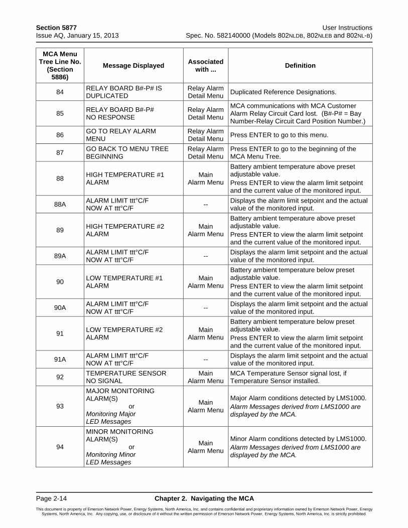
Section 5877 User Instructions Issue AQ, January 15, 2013 Spec. No. 582140000 (Models 802NLDB, 802NLEB and 802NL-B)
Page 2-14 Chapter 2. Navigating the MCA
This document is property of Emerson Network Power, Energy Systems, North America, Inc. and contains confidential and proprietary information owned by Emerson Network Power, Energy Systems, North America, Inc. Any copying, use, or disclosure of it without the written permission of Emerson Network Power, Energy Systems, North America, Inc. is strictly prohibited.
MCA Menu Tree Line No.
(Section 5886)
Message Displayed Associated
with ... Definition
84 RELAY BOARD B#-P# IS DUPLICATED
Relay Alarm Detail Menu
Duplicated Reference Designations.
85 RELAY BOARD B#-P# NO RESPONSE
Relay Alarm Detail Menu
MCA communications with MCA Customer Alarm Relay Circuit Card lost. (B#-P# = Bay Number-Relay Circuit Card Position Number.)
86 GO TO RELAY ALARM MENU
Relay Alarm Detail Menu
Press ENTER to go to this menu.
87 GO BACK TO MENU TREE BEGINNING
Relay Alarm Detail Menu
Press ENTER to go to the beginning of the MCA Menu Tree.
88 HIGH TEMPERATURE #1 ALARM
Main Alarm Menu
Battery ambient temperature above preset adjustable value.
Press ENTER to view the alarm limit setpoint and the current value of the monitored input.
88A ALARM LIMIT ttt°C/F NOW AT ttt°C/F
-- Displays the alarm limit setpoint and the actual value of the monitored input.
89 HIGH TEMPERATURE #2 ALARM
Main Alarm Menu
Battery ambient temperature above preset adjustable value.
Press ENTER to view the alarm limit setpoint and the current value of the monitored input.
89A ALARM LIMIT ttt°C/F NOW AT ttt°C/F
-- Displays the alarm limit setpoint and the actual value of the monitored input.
90 LOW TEMPERATURE #1 ALARM
Main Alarm Menu
Battery ambient temperature below preset adjustable value.
Press ENTER to view the alarm limit setpoint and the current value of the monitored input.
90A ALARM LIMIT ttt°C/F NOW AT ttt°C/F
-- Displays the alarm limit setpoint and the actual value of the monitored input.
91 LOW TEMPERATURE #2 ALARM
Main Alarm Menu
Battery ambient temperature below preset adjustable value.
Press ENTER to view the alarm limit setpoint and the current value of the monitored input.
91A ALARM LIMIT ttt°C/F NOW AT ttt°C/F
-- Displays the alarm limit setpoint and the actual value of the monitored input.
92 TEMPERATURE SENSOR NO SIGNAL
Main Alarm Menu
MCA Temperature Sensor signal lost, if Temperature Sensor installed.
93
MAJOR MONITORING ALARM(S) or Monitoring Major LED Messages
Main Alarm Menu
Major Alarm conditions detected by LMS1000.
Alarm Messages derived from LMS1000 are displayed by the MCA.
94
MINOR MONITORING ALARM(S) or Monitoring Minor LED Messages
Main Alarm Menu
Minor Alarm conditions detected by LMS1000.
Alarm Messages derived from LMS1000 are displayed by the MCA.

User Instructions Section 5877 Spec. No. 582140000 (Models 802NLDB, 802NLEB and 802NL-B) Issue AQ, January 15, 2013
Chapter 2. Navigating the MCA Page 2-15
This document is property of Emerson Network Power, Energy Systems, North America, Inc. and contains confidential and proprietary information owned by Emerson Network Power, Energy Systems, North America, Inc. Any copying, use, or disclosure of it without the written permission of Emerson Network Power, Energy Systems, North America, Inc. is strictly prohibited.
MCA Menu Tree Line No.
(Section 5886)
Message Displayed Associated
with ... Definition
95
MONITORING INFORMATION or Monitoring Info LED Messages
Main Alarm Menu
Status Messages detected by LMS1000.
Status Messages derived from LMS1000 are displayed by the MCA.
96 MONITORING DOES NOT RESPOND
Main Alarm Menu
MCA communications with LMS1000 lost.
97 CONTROLLER FAILURE ####
Main Alarm Menu
MCA failed (#### = type of memory failure)
98 THE CONTROLLER IS INITIALIZING
Main Alarm Menu
The MCA is initializing.
99 TOTAL LOAD CURRENT ALARM
Main Alarm Menu
System load current above preset adjustable value (includes distribution loads monitored by the Distribution Bus Monitoring Circuit Cards and any MCA I/O Circuit Card set as "Distribution" [other setting choice is "Auxiliary"]).
Press ENTER to view the alarm limit setpoint and the current value of the monitored input.
99A ALARM LIMIT aaaaaA NOW AT aaaaaA
-- Displays the alarm limit setpoint and the actual value of the monitored input.
100 DISTRIBUTION GROUP A LOAD ALARM
Main Alarm Menu
Sum of load currents monitored by all Distribution Bus Monitoring Circuit Cards set as Group A designation above preset adjustable value.
Press ENTER to view the alarm limit setpoint and the current value of the monitored input.
100A ALARM LIMIT aaaaaA NOW AT aaaaaA
-- Displays the alarm limit setpoint and the actual value of the monitored input.
101 DISTRIBUTION GROUP B LOAD ALARM
Main Alarm Menu
Sum of load currents monitored by all Distribution Bus Monitoring Circuit Cards set as Group B designation above preset adjustable value.
Press ENTER to view the alarm limit setpoint and the current value of the monitored input.
101A ALARM LIMIT aaaaaA NOW AT aaaaaA
-- Displays the alarm limit setpoint and the actual value of the monitored input.
102 THE DISPLAY DOES NOT RESPOND
Main Alarm Menu
MCA communications with MCA Display lost.
103 GO TO FUNCTION MENU Main
Alarm Menu Press ENTER to go to this menu.
104 GO BACK TO MENU TREE BEGINNING
Main Alarm Menu
Press ENTER to go to the beginning of the MCA Menu Tree.
105 VIEW THE SYSTEM MEASUREMENTS
Function Menu
Press ENTER to go to this menu.
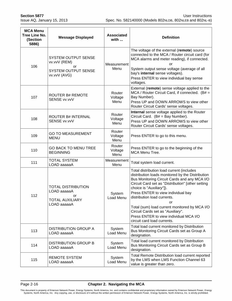
Section 5877 User Instructions Issue AQ, January 15, 2013 Spec. No. 582140000 (Models 802NLDB, 802NLEB and 802NL-B)
Page 2-16 Chapter 2. Navigating the MCA
This document is property of Emerson Network Power, Energy Systems, North America, Inc. and contains confidential and proprietary information owned by Emerson Network Power, Energy Systems, North America, Inc. Any copying, use, or disclosure of it without the written permission of Emerson Network Power, Energy Systems, North America, Inc. is strictly prohibited.
MCA Menu Tree Line No.
(Section 5886)
Message Displayed Associated
with ... Definition
106
SYSTEM OUTPUT SENSE vv.vvV (REM) or SYSTEM OUTPUT SENSE vv.vvV (AVG)
Measurement Menu
The voltage of the external (remote) source connected to the MCA / Router circuit card (for MCA alarms and meter reading), if connected.
or
System output sense voltage (average of all bay's internal sense voltages).
Press ENTER to view individual bay sense voltages.
107 ROUTER B# REMOTE SENSE vv.vvV
Router Voltage Menu
External (remote) sense voltage applied to the MCA / Router Circuit Card, if connected. (B# = Bay Number).
Press UP and DOWN ARROWS to view other Router Circuit Cards' sense voltages.
108 ROUTER B# INTERNAL SENSE vv.vvV
Router Voltage Menu
Internal sense voltage applied to the Router Circuit Card. (B# = Bay Number).
Press UP and DOWN ARROWS to view other Router Circuit Cards' sense voltages.
109 GO TO MEASUREMENT MENU
Router Voltage Menu
Press ENTER to go to this menu.
110 GO BACK TO MENU TREE BEGINNING
Router Voltage Menu
Press ENTER to go to the beginning of the MCA Menu Tree.
111 TOTAL SYSTEM LOAD aaaaaA
Measurement Menu
Total system load current.
112
TOTAL DISTRIBUTION LOAD aaaaaA or TOTAL AUXILIARY LOAD aaaaaA
System Load Menu
Total distribution load current (includes distribution loads monitored by the Distribution Bus Monitoring Circuit Cards and any MCA I/O Circuit Card set as "Distribution" [other setting choice is "Auxiliary"]).
Press ENTER to view individual bay distribution load currents.
or
Total (sum) load current monitored by MCA I/O Circuit Cards set as "Auxiliary".
Press ENTER to view individual MCA I/O circuit card load currents.
113 DISTRIBUTION GROUP A LOAD aaaaaA
System Load Menu
Total load current monitored by Distribution Bus Monitoring Circuit Cards set as Group A designation.
114 DISTRIBUTION GROUP B LOAD aaaaaA
System Load Menu
Total load current monitored by Distribution Bus Monitoring Circuit Cards set as Group B designation.
115 REMOTE SYSTEM LOAD aaaaaA
System Load Menu
Total Remote Distribution load current reported by the LMS when LMS Function Channel 63 value is greater than zero.
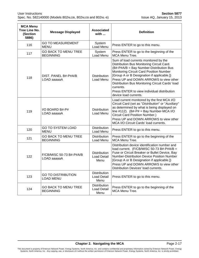
User Instructions Section 5877 Spec. No. 582140000 (Models 802NLDB, 802NLEB and 802NL-B) Issue AQ, January 15, 2013
Chapter 2. Navigating the MCA Page 2-17
This document is property of Emerson Network Power, Energy Systems, North America, Inc. and contains confidential and proprietary information owned by Emerson Network Power, Energy Systems, North America, Inc. Any copying, use, or disclosure of it without the written permission of Emerson Network Power, Energy Systems, North America, Inc. is strictly prohibited.
MCA Menu Tree Line No.
(Section 5886)
Message Displayed Associated
with ... Definition
116 GO TO MEASUREMENT MENU
System Load Menu
Press ENTER to go to this menu.
117 GO BACK TO MENU TREE BEGINNING
System Load Menu
Press ENTER to go to the beginning of the MCA Menu Tree.
118 DIST. PANEL B#-P#A/B LOAD aaaaaA
Distribution Load Menu
Sum of load currents monitored by the Distribution Bus Monitoring Circuit Card. (B#-P#A/B = Bay Number-Distribution Bus Monitoring Circuit Card Position Number [Group A or B Designation if applicable.])
Press UP and DOWN ARROWS to view other Distribution Bus Monitoring Circuit Cards' load currents.
Press ENTER to view individual distribution device load currents.
119 I/O BOARD B#-P# LOAD aaaaaA
Distribution Load Menu
Load current monitored by the first MCA I/O Circuit Card (set as "Distribution" or "Auxiliary" as determined by what is being displayed on line #112). (B#-P# = Bay Number-MCA I/O Circuit Card Position Number.)
Press UP and DOWN ARROWS to view other MCA I/O Circuit Cards' load currents.
120 GO TO SYSTEM LOAD MENU
Distribution Load Menu
Press ENTER to go to this menu.
121 GO BACK TO MENU TREE BEGINNING
Distribution Load Menu
Press ENTER to go to the beginning of the MCA Menu Tree.
122 F/CB/MISC 50-73 B#-P#A/B LOAD aaaaaA
Distribution Load Detail
Menu
Distribution device identification number and load current. (F/CB/MISC 50-73 B#-P#A/B = Fuse or Circuit Breaker or Bullet Device, Bay Number-Distribution Device Position Number [Group A or B Designation if applicable.])
Press UP and DOWN ARROWS to view other Distribution Devices' load currents.
123 GO TO DISTRIBUTION LOAD MENU
Distribution Load Detail
Menu Press ENTER to go to this menu.
124 GO BACK TO MENU TREE BEGINNING
Distribution Load Detail
Menu
Press ENTER to go to the beginning of the MCA Menu Tree.
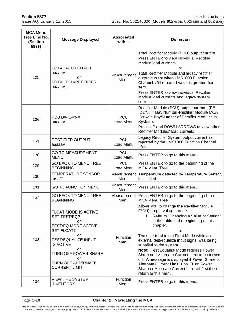
Section 5877 User Instructions Issue AQ, January 15, 2013 Spec. No. 582140000 (Models 802NLDB, 802NLEB and 802NL-B)
Page 2-18 Chapter 2. Navigating the MCA
This document is property of Emerson Network Power, Energy Systems, North America, Inc. and contains confidential and proprietary information owned by Emerson Network Power, Energy Systems, North America, Inc. Any copying, use, or disclosure of it without the written permission of Emerson Network Power, Energy Systems, North America, Inc. is strictly prohibited.
MCA Menu Tree Line No.
(Section 5886)
Message Displayed Associated
with ... Definition
125
TOTAL PCU OUTPUT aaaaaA or TOTAL PCU/RECTIFIER aaaaaA
Measurement Menu
Total Rectifier Module (PCU) output current.
Press ENTER to view individual Rectifier Module load currents.
or
Total Rectifier Module and legacy rectifier output current when LMS1000 Function Channel #64 reported value is greater than zero.
Press ENTER to view individual Rectifier Module load currents and legacy system current.
126 PCU B#-ID#/N# aaaaaA
PCU Load Menu
Rectifier Module (PCU) output current. (B#-ID#/N# = Bay Number-Rectifier Module MCA ID# w/in Bay/Number of Rectifier Modules in System).
Press UP and DOWN ARROWS to view other Rectifier Modules' load currents.
127 RECTIFIER OUTPUT aaaaaA
PCU Load Menu
Legacy Rectifier System output current as reported by the LMS1000 Function Channel #64.
128 GO TO MEASUREMENT MENU
PCU Load Menu
Press ENTER to go to this menu.
129 GO BACK TO MENU TREE BEGINNING
PCU Load Menu
Press ENTER to go to the beginning of the MCA Menu Tree.
130 TEMPERATURE SENSOR
ttt C/F
Measurement Menu
Temperature detected by Temperature Sensor, if installed.
131 GO TO FUNCTION MENU Measurement
Menu Press ENTER to go to this menu.
132 GO BACK TO MENU TREE BEGINNING
Measurement Menu
Press ENTER to go to the beginning of the MCA Menu Tree.
133
FLOAT MODE IS ACTIVE SET TEST/EQ? or TEST/EQ MODE ACTIVE SET FLOAT? or TEST/EQUALIZE INPUT IS ACTIVE or TURN OFF POWER SHARE or TURN OFF ALTERNATE CURRENT LIMIT
Function Menu
Allows you to change the Rectifier Module (PCU) output voltage mode.
1. Refer to "Changing a Value or Setting" in the table at the beginning of this chapter.
or
The user tried to set Float Mode while an external test/equalize input signal was being supplied to the system.
Note: Test/Equalize Mode requires Power Share and Alternate Current Limit to be turned off. A message is displayed if Power Share or Alternate Current Limit is on. Turn Power Share or Alternate Current Limit off first then return to this menu.
134 VIEW THE SYSTEM INVENTORY
Function Menu
Press ENTER to go to this menu.
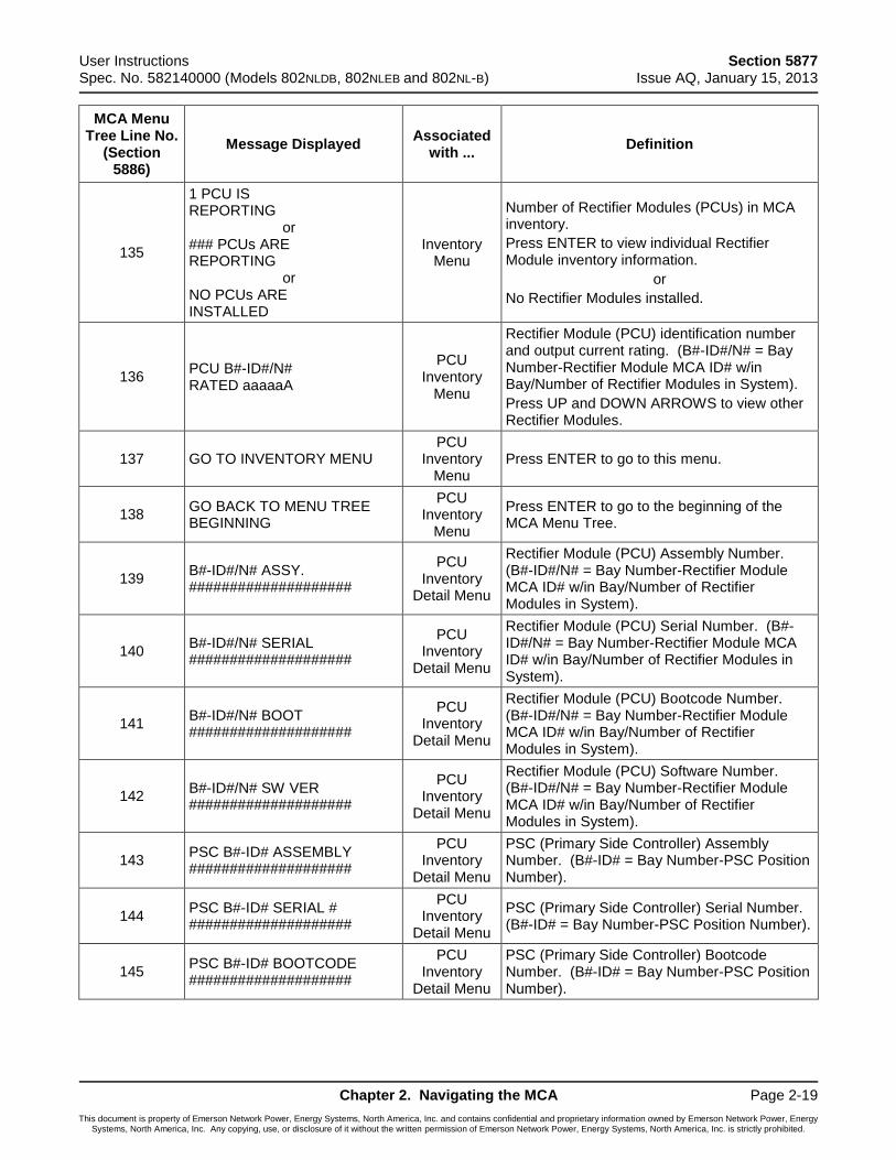
User Instructions Section 5877 Spec. No. 582140000 (Models 802NLDB, 802NLEB and 802NL-B) Issue AQ, January 15, 2013
Chapter 2. Navigating the MCA Page 2-19
This document is property of Emerson Network Power, Energy Systems, North America, Inc. and contains confidential and proprietary information owned by Emerson Network Power, Energy Systems, North America, Inc. Any copying, use, or disclosure of it without the written permission of Emerson Network Power, Energy Systems, North America, Inc. is strictly prohibited.
MCA Menu Tree Line No.
(Section 5886)
Message Displayed Associated
with ... Definition
135
1 PCU IS REPORTING or ### PCUs ARE REPORTING or NO PCUs ARE INSTALLED
Inventory Menu
Number of Rectifier Modules (PCUs) in MCA inventory.
Press ENTER to view individual Rectifier Module inventory information.
or
No Rectifier Modules installed.
136 PCU B#-ID#/N# RATED aaaaaA
PCU Inventory
Menu
Rectifier Module (PCU) identification number and output current rating. (B#-ID#/N# = Bay Number-Rectifier Module MCA ID# w/in Bay/Number of Rectifier Modules in System).
Press UP and DOWN ARROWS to view other Rectifier Modules.
137 GO TO INVENTORY MENU PCU
Inventory Menu
Press ENTER to go to this menu.
138 GO BACK TO MENU TREE BEGINNING
PCU Inventory
Menu
Press ENTER to go to the beginning of the MCA Menu Tree.
139 B#-ID#/N# ASSY. ####################
PCU Inventory
Detail Menu
Rectifier Module (PCU) Assembly Number. (B#-ID#/N# = Bay Number-Rectifier Module MCA ID# w/in Bay/Number of Rectifier Modules in System).
140 B#-ID#/N# SERIAL ####################
PCU Inventory
Detail Menu
Rectifier Module (PCU) Serial Number. (B#-ID#/N# = Bay Number-Rectifier Module MCA ID# w/in Bay/Number of Rectifier Modules in System).
141 B#-ID#/N# BOOT ####################
PCU Inventory
Detail Menu
Rectifier Module (PCU) Bootcode Number. (B#-ID#/N# = Bay Number-Rectifier Module MCA ID# w/in Bay/Number of Rectifier Modules in System).
142 B#-ID#/N# SW VER ####################
PCU Inventory
Detail Menu
Rectifier Module (PCU) Software Number. (B#-ID#/N# = Bay Number-Rectifier Module MCA ID# w/in Bay/Number of Rectifier Modules in System).
143 PSC B#-ID# ASSEMBLY ####################
PCU Inventory
Detail Menu
PSC (Primary Side Controller) Assembly Number. (B#-ID# = Bay Number-PSC Position Number).
144 PSC B#-ID# SERIAL # ####################
PCU Inventory
Detail Menu
PSC (Primary Side Controller) Serial Number. (B#-ID# = Bay Number-PSC Position Number).
145 PSC B#-ID# BOOTCODE ####################
PCU Inventory
Detail Menu
PSC (Primary Side Controller) Bootcode Number. (B#-ID# = Bay Number-PSC Position Number).
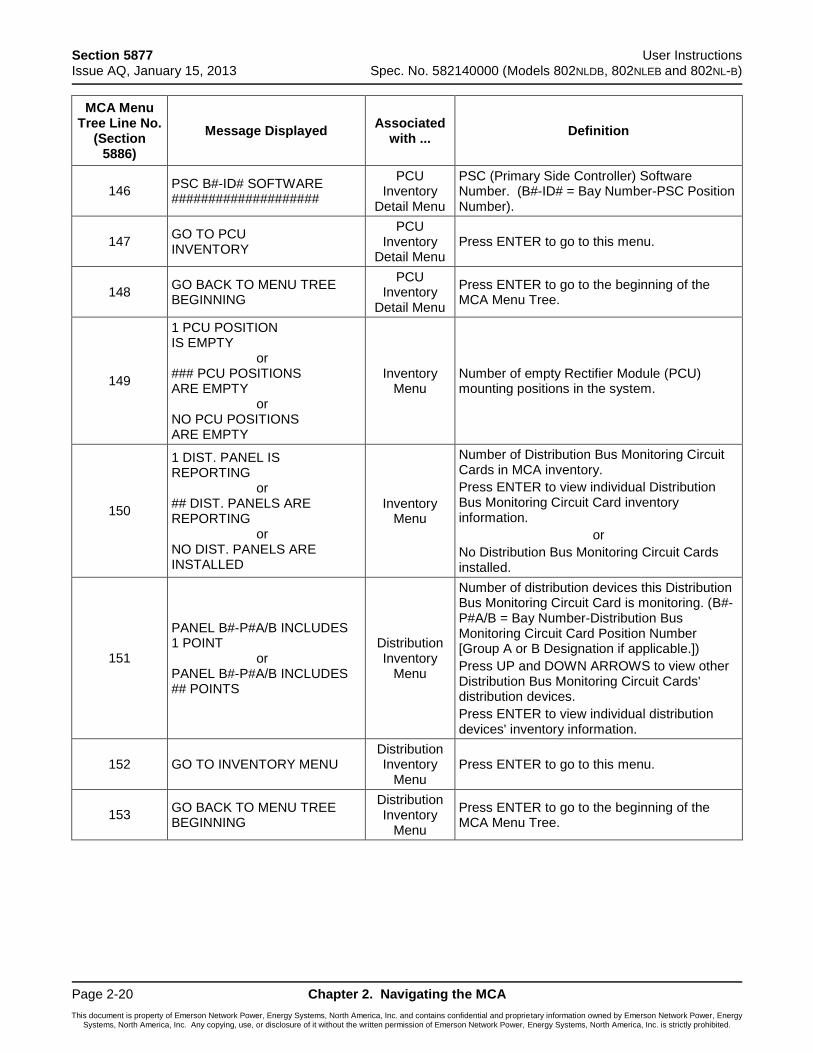
Section 5877 User Instructions Issue AQ, January 15, 2013 Spec. No. 582140000 (Models 802NLDB, 802NLEB and 802NL-B)
Page 2-20 Chapter 2. Navigating the MCA
This document is property of Emerson Network Power, Energy Systems, North America, Inc. and contains confidential and proprietary information owned by Emerson Network Power, Energy Systems, North America, Inc. Any copying, use, or disclosure of it without the written permission of Emerson Network Power, Energy Systems, North America, Inc. is strictly prohibited.
MCA Menu Tree Line No.
(Section 5886)
Message Displayed Associated
with ... Definition
146 PSC B#-ID# SOFTWARE ####################
PCU Inventory
Detail Menu
PSC (Primary Side Controller) Software Number. (B#-ID# = Bay Number-PSC Position Number).
147 GO TO PCU INVENTORY
PCU Inventory
Detail Menu Press ENTER to go to this menu.
148 GO BACK TO MENU TREE BEGINNING
PCU Inventory
Detail Menu
Press ENTER to go to the beginning of the MCA Menu Tree.
149
1 PCU POSITION IS EMPTY or ### PCU POSITIONS ARE EMPTY or NO PCU POSITIONS ARE EMPTY
Inventory Menu
Number of empty Rectifier Module (PCU) mounting positions in the system.
150
1 DIST. PANEL IS REPORTING or ## DIST. PANELS ARE REPORTING or NO DIST. PANELS ARE INSTALLED
Inventory Menu
Number of Distribution Bus Monitoring Circuit Cards in MCA inventory.
Press ENTER to view individual Distribution Bus Monitoring Circuit Card inventory information.
or
No Distribution Bus Monitoring Circuit Cards installed.
151
PANEL B#-P#A/B INCLUDES 1 POINT or PANEL B#-P#A/B INCLUDES ## POINTS
Distribution Inventory
Menu
Number of distribution devices this Distribution Bus Monitoring Circuit Card is monitoring. (B#-P#A/B = Bay Number-Distribution Bus Monitoring Circuit Card Position Number [Group A or B Designation if applicable.])
Press UP and DOWN ARROWS to view other Distribution Bus Monitoring Circuit Cards' distribution devices.
Press ENTER to view individual distribution devices' inventory information.
152 GO TO INVENTORY MENU Distribution Inventory
Menu Press ENTER to go to this menu.
153 GO BACK TO MENU TREE BEGINNING
Distribution Inventory
Menu
Press ENTER to go to the beginning of the MCA Menu Tree.
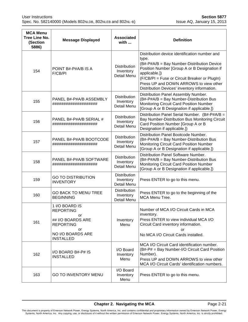
User Instructions Section 5877 Spec. No. 582140000 (Models 802NLDB, 802NLEB and 802NL-B) Issue AQ, January 15, 2013
Chapter 2. Navigating the MCA Page 2-21
This document is property of Emerson Network Power, Energy Systems, North America, Inc. and contains confidential and proprietary information owned by Emerson Network Power, Energy Systems, North America, Inc. Any copying, use, or disclosure of it without the written permission of Emerson Network Power, Energy Systems, North America, Inc. is strictly prohibited.
MCA Menu Tree Line No.
(Section 5886)
Message Displayed Associated
with ... Definition
154 POINT B#-P#A/B IS A F/CB/PI
Distribution Inventory
Detail Menu
Distribution device identification number and type.
(B#-P#A/B = Bay Number-Distribution Device Position Number [Group A or B Designation if applicable.])
(F/CB/PI = Fuse or Circuit Breaker or PlugIn)
Press UP and DOWN ARROWS to view other Distribution Devices' inventory information.
155 PANEL B#-P#A/B ASSEMBLY ####################
Distribution Inventory
Detail Menu
Distribution Panel Assembly Number. (B#-P#A/B = Bay Number-Distribution Bus Monitoring Circuit Card Position Number [Group A or B Designation if applicable.])
156 PANEL B#-P#A/B SERIAL # ####################
Distribution Inventory
Detail Menu
Distribution Panel Serial Number. (B#-P#A/B = Bay Number-Distribution Bus Monitoring Circuit Card Position Number [Group A or B Designation if applicable.])
157 PANEL B#-P#A/B BOOTCODE ####################
Distribution Inventory
Detail Menu
Distribution Panel Bootcode Number. (B#-P#A/B = Bay Number-Distribution Bus Monitoring Circuit Card Position Number [Group A or B Designation if applicable.])
158 PANEL B#-P#A/B SOFTWARE ####################
Distribution Inventory
Detail Menu
Distribution Panel Software Number. (B#-P#A/B = Bay Number-Distribution Bus Monitoring Circuit Card Position Number [Group A or B Designation if applicable.])
159 GO TO DISTRIBUTION INVENTORY
Distribution Inventory
Detail Menu Press ENTER to go to this menu.
160 GO BACK TO MENU TREE BEGINNING
Distribution Inventory
Detail Menu
Press ENTER to go to the beginning of the MCA Menu Tree.
161
1 I/O BOARD IS REPORTING or ## I/O BOARDS ARE REPORTING or NO I/O BOARDS ARE INSTALLED
Inventory Menu
Number of MCA I/O Circuit Cards in MCA inventory.
Press ENTER to view individual MCA I/O Circuit Card inventory information.
or
No MCA I/O Circuit Cards installed.
162 I/O BOARD B#-P# IS INSTALLED
I/O Board Inventory
Menu
MCA I/O Circuit Card identification number. (B#-P# = Bay Number-I/O Circuit Card Position Number).
Press UP and DOWN ARROWS to view other MCA I/O Circuit Cards' identification numbers.
163 GO TO INVENTORY MENU I/O Board Inventory
Menu Press ENTER to go to this menu.
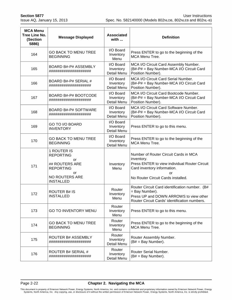
Section 5877 User Instructions Issue AQ, January 15, 2013 Spec. No. 582140000 (Models 802NLDB, 802NLEB and 802NL-B)
Page 2-22 Chapter 2. Navigating the MCA
This document is property of Emerson Network Power, Energy Systems, North America, Inc. and contains confidential and proprietary information owned by Emerson Network Power, Energy Systems, North America, Inc. Any copying, use, or disclosure of it without the written permission of Emerson Network Power, Energy Systems, North America, Inc. is strictly prohibited.
MCA Menu Tree Line No.
(Section 5886)
Message Displayed Associated
with ... Definition
164 GO BACK TO MENU TREE BEGINNING
I/O Board Inventory
Menu
Press ENTER to go to the beginning of the MCA Menu Tree.
165 BOARD B#-P# ASSEMBLY ####################
I/O Board Inventory
Detail Menu
MCA I/O Circuit Card Assembly Number. (B#-P# = Bay Number-MCA I/O Circuit Card Position Number).
166 BOARD B#-P# SERIAL # ####################
I/O Board Inventory
Detail Menu
MCA I/O Circuit Card Serial Number. (B#-P# = Bay Number-MCA I/O Circuit Card Position Number).
167 BOARD B#-P# BOOTCODE ####################
I/O Board Inventory
Detail Menu
MCA I/O Circuit Card Bootcode Number. (B#-P# = Bay Number-MCA I/O Circuit Card Position Number).
168 BOARD B#-P# SOFTWARE ####################
I/O Board Inventory
Detail Menu
MCA I/O Circuit Card Software Number. (B#-P# = Bay Number-MCA I/O Circuit Card Position Number).
169 GO TO I/O BOARD INVENTORY
I/O Board Inventory
Detail Menu Press ENTER to go to this menu.
170 GO BACK TO MENU TREE BEGINNING
I/O Board Inventory
Detail Menu
Press ENTER to go to the beginning of the MCA Menu Tree.
171
1 ROUTER IS REPORTING or ## ROUTERS ARE REPORTING or NO ROUTERS ARE INSTALLED
Inventory Menu
Number of Router Circuit Cards in MCA inventory.
Press ENTER to view individual Router Circuit Card inventory information.
or
No Router Circuit Cards installed.
172 ROUTER B# IS INSTALLED
Router Inventory
Menu
Router Circuit Card identification number. (B# = Bay Number).
Press UP and DOWN ARROWS to view other Router Circuit Cards' identification numbers.
173 GO TO INVENTORY MENU Router
Inventory Menu
Press ENTER to go to this menu.
174 GO BACK TO MENU TREE BEGINNING
Router Inventory
Menu
Press ENTER to go to the beginning of the MCA Menu Tree.
175 ROUTER B# ASSEMBLY ####################
Router Inventory
Detail Menu
Router Assembly Number. (B# = Bay Number).
176 ROUTER B# SERIAL # ####################
Router Inventory
Detail Menu
Router Serial Number. (B# = Bay Number).
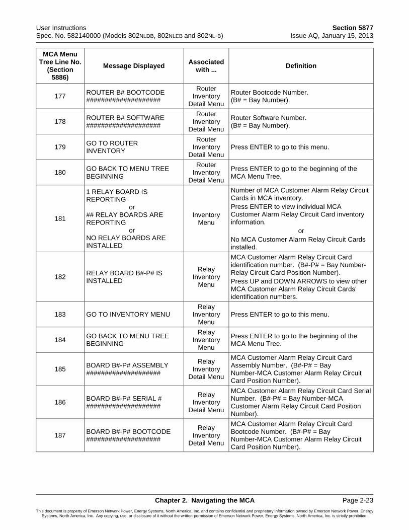
User Instructions Section 5877 Spec. No. 582140000 (Models 802NLDB, 802NLEB and 802NL-B) Issue AQ, January 15, 2013
Chapter 2. Navigating the MCA Page 2-23
This document is property of Emerson Network Power, Energy Systems, North America, Inc. and contains confidential and proprietary information owned by Emerson Network Power, Energy Systems, North America, Inc. Any copying, use, or disclosure of it without the written permission of Emerson Network Power, Energy Systems, North America, Inc. is strictly prohibited.
MCA Menu Tree Line No.
(Section 5886)
Message Displayed Associated
with ... Definition
177 ROUTER B# BOOTCODE ####################
Router Inventory
Detail Menu
Router Bootcode Number. (B# = Bay Number).
178 ROUTER B# SOFTWARE ####################
Router Inventory
Detail Menu
Router Software Number. (B# = Bay Number).
179 GO TO ROUTER INVENTORY
Router Inventory
Detail Menu Press ENTER to go to this menu.
180 GO BACK TO MENU TREE BEGINNING
Router Inventory
Detail Menu
Press ENTER to go to the beginning of the MCA Menu Tree.
181
1 RELAY BOARD IS REPORTING or ## RELAY BOARDS ARE REPORTING or NO RELAY BOARDS ARE INSTALLED
Inventory Menu
Number of MCA Customer Alarm Relay Circuit Cards in MCA inventory.
Press ENTER to view individual MCA Customer Alarm Relay Circuit Card inventory information.
or
No MCA Customer Alarm Relay Circuit Cards installed.
182 RELAY BOARD B#-P# IS INSTALLED
Relay Inventory
Menu
MCA Customer Alarm Relay Circuit Card identification number. (B#-P# = Bay Number-Relay Circuit Card Position Number).
Press UP and DOWN ARROWS to view other MCA Customer Alarm Relay Circuit Cards' identification numbers.
183 GO TO INVENTORY MENU Relay
Inventory Menu
Press ENTER to go to this menu.
184 GO BACK TO MENU TREE BEGINNING
Relay Inventory
Menu
Press ENTER to go to the beginning of the MCA Menu Tree.
185 BOARD B#-P# ASSEMBLY ####################
Relay Inventory
Detail Menu
MCA Customer Alarm Relay Circuit Card Assembly Number. (B#-P# = Bay Number-MCA Customer Alarm Relay Circuit Card Position Number).
186 BOARD B#-P# SERIAL # ####################
Relay Inventory
Detail Menu
MCA Customer Alarm Relay Circuit Card Serial Number. (B#-P# = Bay Number-MCA Customer Alarm Relay Circuit Card Position Number).
187 BOARD B#-P# BOOTCODE ####################
Relay Inventory
Detail Menu
MCA Customer Alarm Relay Circuit Card Bootcode Number. (B#-P# = Bay Number-MCA Customer Alarm Relay Circuit Card Position Number).
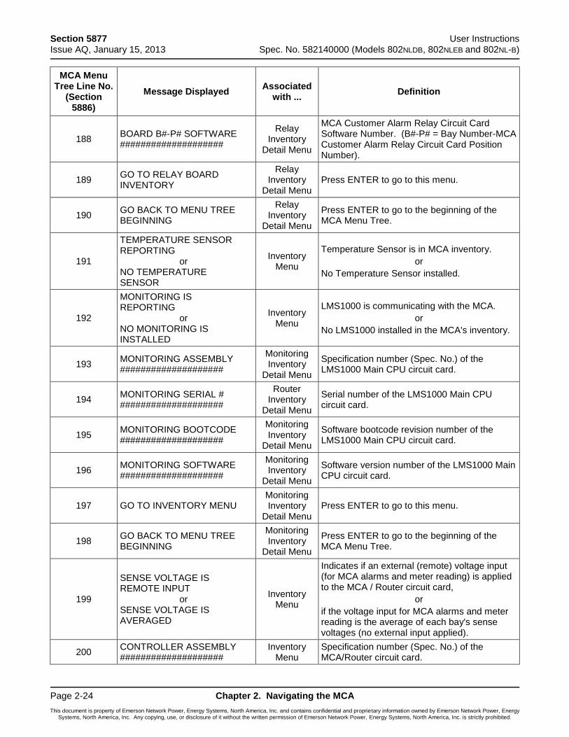
Section 5877 User Instructions Issue AQ, January 15, 2013 Spec. No. 582140000 (Models 802NLDB, 802NLEB and 802NL-B)
Page 2-24 Chapter 2. Navigating the MCA
This document is property of Emerson Network Power, Energy Systems, North America, Inc. and contains confidential and proprietary information owned by Emerson Network Power, Energy Systems, North America, Inc. Any copying, use, or disclosure of it without the written permission of Emerson Network Power, Energy Systems, North America, Inc. is strictly prohibited.
MCA Menu Tree Line No.
(Section 5886)
Message Displayed Associated
with ... Definition
188 BOARD B#-P# SOFTWARE ####################
Relay Inventory
Detail Menu
MCA Customer Alarm Relay Circuit Card Software Number. (B#-P# = Bay Number-MCA Customer Alarm Relay Circuit Card Position Number).
189 GO TO RELAY BOARD INVENTORY
Relay Inventory
Detail Menu Press ENTER to go to this menu.
190 GO BACK TO MENU TREE BEGINNING
Relay Inventory
Detail Menu
Press ENTER to go to the beginning of the MCA Menu Tree.
191
TEMPERATURE SENSOR REPORTING or NO TEMPERATURE SENSOR
Inventory Menu
Temperature Sensor is in MCA inventory.
or
No Temperature Sensor installed.
192
MONITORING IS REPORTING or NO MONITORING IS INSTALLED
Inventory Menu
LMS1000 is communicating with the MCA.
or
No LMS1000 installed in the MCA's inventory.
193 MONITORING ASSEMBLY ####################
Monitoring Inventory
Detail Menu
Specification number (Spec. No.) of the LMS1000 Main CPU circuit card.
194 MONITORING SERIAL # ####################
Router Inventory
Detail Menu
Serial number of the LMS1000 Main CPU circuit card.
195 MONITORING BOOTCODE ####################
Monitoring Inventory
Detail Menu
Software bootcode revision number of the LMS1000 Main CPU circuit card.
196 MONITORING SOFTWARE ####################
Monitoring Inventory
Detail Menu
Software version number of the LMS1000 Main CPU circuit card.
197 GO TO INVENTORY MENU Monitoring Inventory
Detail Menu Press ENTER to go to this menu.
198 GO BACK TO MENU TREE BEGINNING
Monitoring Inventory
Detail Menu
Press ENTER to go to the beginning of the MCA Menu Tree.
199
SENSE VOLTAGE IS REMOTE INPUT or SENSE VOLTAGE IS AVERAGED
Inventory Menu
Indicates if an external (remote) voltage input (for MCA alarms and meter reading) is applied to the MCA / Router circuit card,
or
if the voltage input for MCA alarms and meter reading is the average of each bay's sense voltages (no external input applied).
200 CONTROLLER ASSEMBLY ####################
Inventory Menu
Specification number (Spec. No.) of the MCA/Router circuit card.
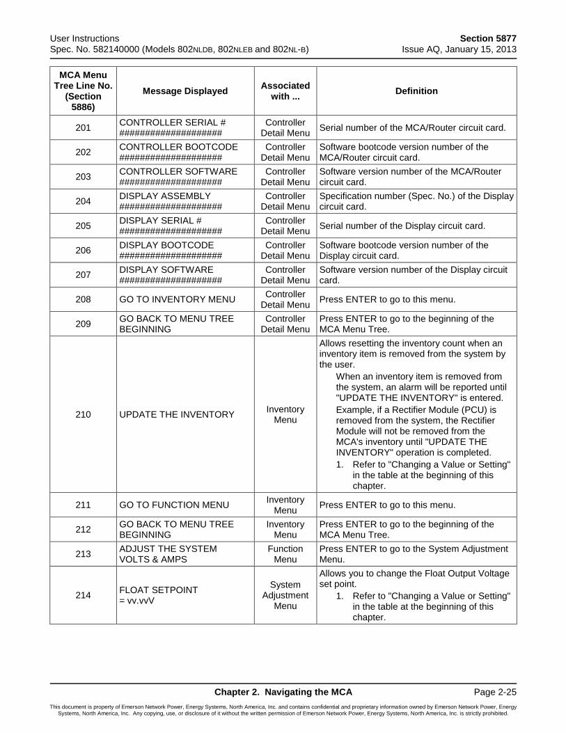
User Instructions Section 5877 Spec. No. 582140000 (Models 802NLDB, 802NLEB and 802NL-B) Issue AQ, January 15, 2013
Chapter 2. Navigating the MCA Page 2-25
This document is property of Emerson Network Power, Energy Systems, North America, Inc. and contains confidential and proprietary information owned by Emerson Network Power, Energy Systems, North America, Inc. Any copying, use, or disclosure of it without the written permission of Emerson Network Power, Energy Systems, North America, Inc. is strictly prohibited.
MCA Menu Tree Line No.
(Section 5886)
Message Displayed Associated
with ... Definition
201 CONTROLLER SERIAL # ####################
Controller Detail Menu
Serial number of the MCA/Router circuit card.
202 CONTROLLER BOOTCODE ####################
Controller Detail Menu
Software bootcode version number of the MCA/Router circuit card.
203 CONTROLLER SOFTWARE ####################
Controller Detail Menu
Software version number of the MCA/Router circuit card.
204 DISPLAY ASSEMBLY ####################
Controller Detail Menu
Specification number (Spec. No.) of the Display circuit card.
205 DISPLAY SERIAL # ####################
Controller Detail Menu
Serial number of the Display circuit card.
206 DISPLAY BOOTCODE ####################
Controller Detail Menu
Software bootcode version number of the Display circuit card.
207 DISPLAY SOFTWARE ####################
Controller Detail Menu
Software version number of the Display circuit card.
208 GO TO INVENTORY MENU Controller
Detail Menu Press ENTER to go to this menu.
209 GO BACK TO MENU TREE BEGINNING
Controller Detail Menu
Press ENTER to go to the beginning of the MCA Menu Tree.
210 UPDATE THE INVENTORY Inventory
Menu
Allows resetting the inventory count when an inventory item is removed from the system by the user.
When an inventory item is removed from the system, an alarm will be reported until "UPDATE THE INVENTORY" is entered.
Example, if a Rectifier Module (PCU) is removed from the system, the Rectifier Module will not be removed from the MCA's inventory until "UPDATE THE INVENTORY" operation is completed.
1. Refer to "Changing a Value or Setting" in the table at the beginning of this chapter.
211 GO TO FUNCTION MENU Inventory
Menu Press ENTER to go to this menu.
212 GO BACK TO MENU TREE BEGINNING
Inventory Menu
Press ENTER to go to the beginning of the MCA Menu Tree.
213 ADJUST THE SYSTEM VOLTS & AMPS
Function Menu
Press ENTER to go to the System Adjustment Menu.
214 FLOAT SETPOINT = vv.vvV
System Adjustment
Menu
Allows you to change the Float Output Voltage set point.
1. Refer to "Changing a Value or Setting" in the table at the beginning of this chapter.
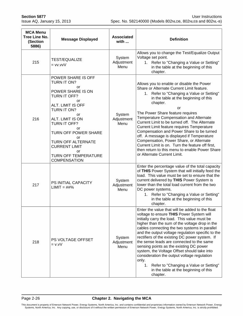
Section 5877 User Instructions Issue AQ, January 15, 2013 Spec. No. 582140000 (Models 802NLDB, 802NLEB and 802NL-B)
Page 2-26 Chapter 2. Navigating the MCA
This document is property of Emerson Network Power, Energy Systems, North America, Inc. and contains confidential and proprietary information owned by Emerson Network Power, Energy Systems, North America, Inc. Any copying, use, or disclosure of it without the written permission of Emerson Network Power, Energy Systems, North America, Inc. is strictly prohibited.
MCA Menu Tree Line No.
(Section 5886)
Message Displayed Associated
with ... Definition
215 TEST/EQUALIZE
= vv.vvV
System Adjustment
Menu
Allows you to change the Test/Equalize Output Voltage set point.
1. Refer to "Changing a Value or Setting" in the table at the beginning of this chapter.
216
POWER SHARE IS OFF TURN IT ON? or POWER SHARE IS ON TURN IT OFF? or ALT. LIMIT IS OFF TURN IT ON? or ALT. LIMIT IS ON TURN IT OFF? or TURN OFF POWER SHARE or TURN OFF ALTERNATE CURRENT LIMIT or TURN OFF TEMPERATURE COMPENSATION
System Adjustment
Menu
Allows you to enable or disable the Power Share or Alternate Current Limit feature.
1. Refer to "Changing a Value or Setting" in the table at the beginning of this chapter.
or
The Power Share feature requires Temperature Compensation and Alternate Current Limit to be turned off. The Alternate Current Limit feature requires Temperature Compensation and Power Share to be turned off. A message is displayed if Temperature Compensation, Power Share, or Alternate Current Limit is on. Turn the feature off first, then return to this menu to enable Power Share or Alternate Current Limit.
217 PS INITIAL CAPACITY LIMIT = ##%
System Adjustment
Menu
Enter the percentage value of the total capacity of THIS Power System that will initially feed the load. This value must be set to ensure that the current delivered by THIS Power System is lower than the total load current from the two DC power systems.
1. Refer to "Changing a Value or Setting" in the table at the beginning of this chapter.
218 PS VOLTAGE OFFSET = v.vV
System Adjustment
Menu
Enter the value that will be added to the float voltage to ensure THIS Power System will initially carry the load. This value must be higher than the sum of the voltage drop in the cables connecting the two systems in parallel and the output voltage regulation specific to the rectifiers of the existing DC power system. If the sense leads are connected to the same sensing points as the existing DC power system, the Voltage Offset should take into consideration the output voltage regulation only.
1. Refer to "Changing a Value or Setting" in the table at the beginning of this chapter.
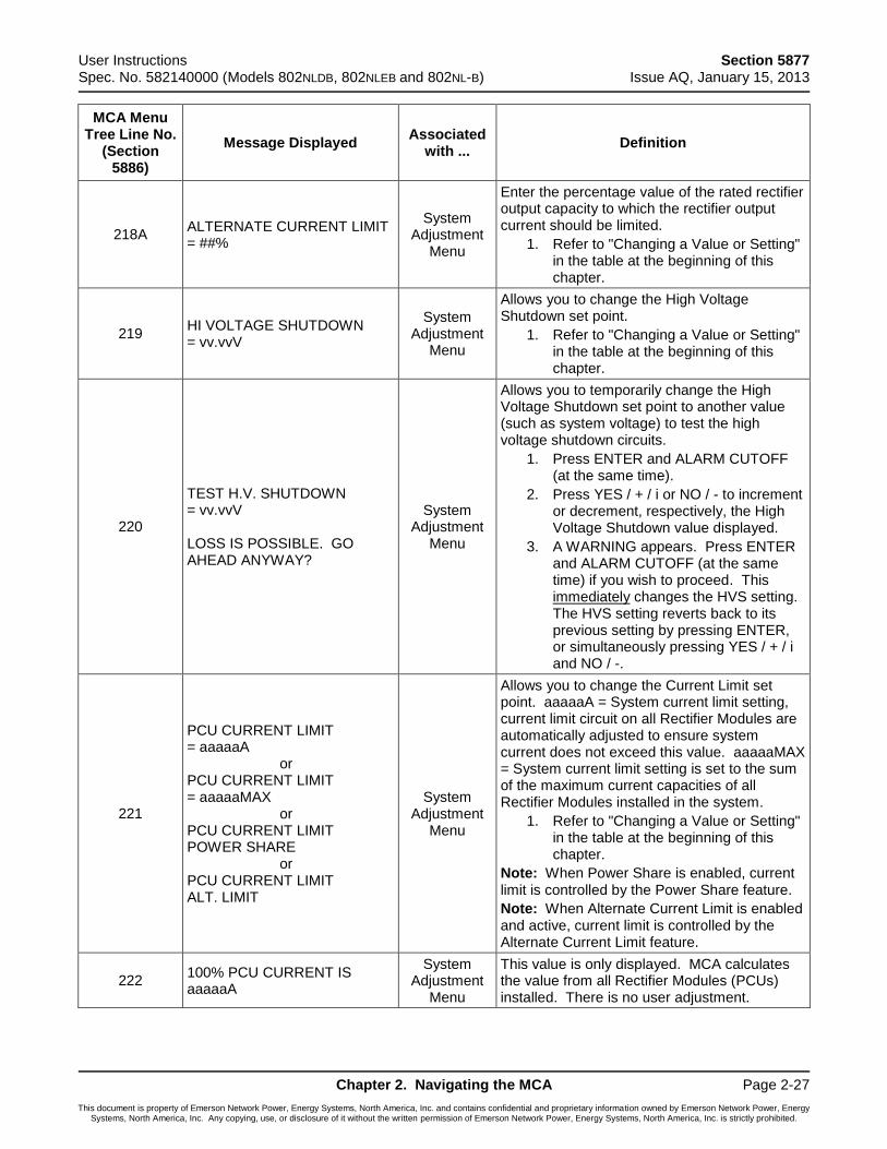
User Instructions Section 5877 Spec. No. 582140000 (Models 802NLDB, 802NLEB and 802NL-B) Issue AQ, January 15, 2013
Chapter 2. Navigating the MCA Page 2-27
This document is property of Emerson Network Power, Energy Systems, North America, Inc. and contains confidential and proprietary information owned by Emerson Network Power, Energy Systems, North America, Inc. Any copying, use, or disclosure of it without the written permission of Emerson Network Power, Energy Systems, North America, Inc. is strictly prohibited.
MCA Menu Tree Line No.
(Section 5886)
Message Displayed Associated
with ... Definition
218A ALTERNATE CURRENT LIMIT = ##%
System Adjustment
Menu
Enter the percentage value of the rated rectifier output capacity to which the rectifier output current should be limited.
1. Refer to "Changing a Value or Setting" in the table at the beginning of this chapter.
219 HI VOLTAGE SHUTDOWN = vv.vvV
System Adjustment
Menu
Allows you to change the High Voltage Shutdown set point.
1. Refer to "Changing a Value or Setting" in the table at the beginning of this chapter.
220
TEST H.V. SHUTDOWN = vv.vvV LOSS IS POSSIBLE. GO AHEAD ANYWAY?
System Adjustment
Menu
Allows you to temporarily change the High Voltage Shutdown set point to another value (such as system voltage) to test the high voltage shutdown circuits.
1. Press ENTER and ALARM CUTOFF (at the same time).
2. Press YES / + / i or NO / - to increment or decrement, respectively, the High Voltage Shutdown value displayed.
3. A WARNING appears. Press ENTER and ALARM CUTOFF (at the same time) if you wish to proceed. This UimmediatelyU changes the HVS setting. The HVS setting reverts back to its previous setting by pressing ENTER, or simultaneously pressing YES / + / i and NO / -.
221
PCU CURRENT LIMIT = aaaaaA or PCU CURRENT LIMIT = aaaaaMAX or PCU CURRENT LIMIT POWER SHARE or PCU CURRENT LIMIT ALT. LIMIT
System Adjustment
Menu
Allows you to change the Current Limit set point. aaaaaA = System current limit setting, current limit circuit on all Rectifier Modules are automatically adjusted to ensure system current does not exceed this value. aaaaaMAX = System current limit setting is set to the sum of the maximum current capacities of all Rectifier Modules installed in the system.
1. Refer to "Changing a Value or Setting" in the table at the beginning of this chapter.
Note: When Power Share is enabled, current limit is controlled by the Power Share feature.
Note: When Alternate Current Limit is enabled and active, current limit is controlled by the Alternate Current Limit feature.
222 100% PCU CURRENT IS aaaaaA
System Adjustment
Menu
This value is only displayed. MCA calculates the value from all Rectifier Modules (PCUs) installed. There is no user adjustment.
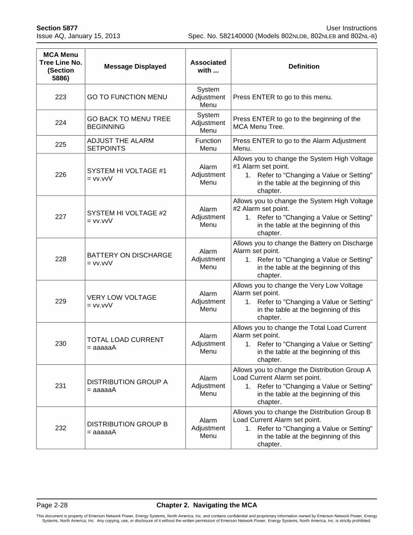
Section 5877 User Instructions Issue AQ, January 15, 2013 Spec. No. 582140000 (Models 802NLDB, 802NLEB and 802NL-B)
Page 2-28 Chapter 2. Navigating the MCA
This document is property of Emerson Network Power, Energy Systems, North America, Inc. and contains confidential and proprietary information owned by Emerson Network Power, Energy Systems, North America, Inc. Any copying, use, or disclosure of it without the written permission of Emerson Network Power, Energy Systems, North America, Inc. is strictly prohibited.
MCA Menu Tree Line No.
(Section 5886)
Message Displayed Associated
with ... Definition
223 GO TO FUNCTION MENU System
Adjustment Menu
Press ENTER to go to this menu.
224 GO BACK TO MENU TREE BEGINNING
System Adjustment
Menu
Press ENTER to go to the beginning of the MCA Menu Tree.
225 ADJUST THE ALARM SETPOINTS
Function Menu
Press ENTER to go to the Alarm Adjustment Menu.
226 SYSTEM HI VOLTAGE #1 = vv.vvV
Alarm Adjustment
Menu
Allows you to change the System High Voltage #1 Alarm set point.
1. Refer to "Changing a Value or Setting" in the table at the beginning of this chapter.
227 SYSTEM HI VOLTAGE #2 = vv.vvV
Alarm Adjustment
Menu
Allows you to change the System High Voltage #2 Alarm set point.
1. Refer to "Changing a Value or Setting" in the table at the beginning of this chapter.
228 BATTERY ON DISCHARGE = vv.vvV
Alarm Adjustment
Menu
Allows you to change the Battery on Discharge Alarm set point.
1. Refer to "Changing a Value or Setting" in the table at the beginning of this chapter.
229 VERY LOW VOLTAGE = vv.vvV
Alarm Adjustment
Menu
Allows you to change the Very Low Voltage Alarm set point.
1. Refer to "Changing a Value or Setting" in the table at the beginning of this chapter.
230 TOTAL LOAD CURRENT = aaaaaA
Alarm Adjustment
Menu
Allows you to change the Total Load Current Alarm set point.
1. Refer to "Changing a Value or Setting" in the table at the beginning of this chapter.
231 DISTRIBUTION GROUP A = aaaaaA
Alarm Adjustment
Menu
Allows you to change the Distribution Group A Load Current Alarm set point.
1. Refer to "Changing a Value or Setting" in the table at the beginning of this chapter.
232 DISTRIBUTION GROUP B = aaaaaA
Alarm Adjustment
Menu
Allows you to change the Distribution Group B Load Current Alarm set point.
1. Refer to "Changing a Value or Setting" in the table at the beginning of this chapter.
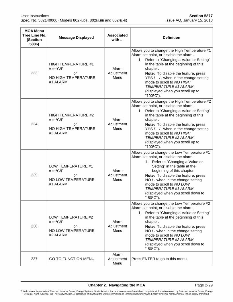
User Instructions Section 5877 Spec. No. 582140000 (Models 802NLDB, 802NLEB and 802NL-B) Issue AQ, January 15, 2013
Chapter 2. Navigating the MCA Page 2-29
This document is property of Emerson Network Power, Energy Systems, North America, Inc. and contains confidential and proprietary information owned by Emerson Network Power, Energy Systems, North America, Inc. Any copying, use, or disclosure of it without the written permission of Emerson Network Power, Energy Systems, North America, Inc. is strictly prohibited.
MCA Menu Tree Line No.
(Section 5886)
Message Displayed Associated
with ... Definition
233
HIGH TEMPERATURE #1
= ttt C/F or NO HIGH TEMPERATURE #1 ALARM
Alarm Adjustment
Menu
Allows you to change the High Temperature #1 Alarm set point, or disable the alarm.
1. Refer to "Changing a Value or Setting" in the table at the beginning of this chapter.
Note: To disable the feature, press YES / + / i when in the change setting mode to scroll to NO HIGH TEMPERATURE #1 ALARM (displayed when you scroll up to
"100 C").
234
HIGH TEMPERATURE #2
= ttt C/F or NO HIGH TEMPERATURE #2 ALARM
Alarm Adjustment
Menu
Allows you to change the High Temperature #2 Alarm set point, or disable the alarm.
1. Refer to "Changing a Value or Setting" in the table at the beginning of this chapter.
Note: To disable the feature, press YES / + / i when in the change setting mode to scroll to NO HIGH TEMPERATURE #2 ALARM (displayed when you scroll up to
"100 C").
235
LOW TEMPERATURE #1
= ttt C/F or NO LOW TEMPERATURE #1 ALARM
Alarm Adjustment
Menu
Allows you to change the Low Temperature #1 Alarm set point, or disable the alarm.
1. Refer to "Changing a Value or Setting" in the table at the beginning of this chapter.
Note: To disable the feature, press NO / - when in the change setting mode to scroll to NO LOW TEMPERATURE #1 ALARM (displayed when you scroll down to
"-50 C").
236
LOW TEMPERATURE #2
= ttt C/F or NO LOW TEMPERATURE #2 ALARM
Alarm Adjustment
Menu
Allows you to change the Low Temperature #2 Alarm set point, or disable the alarm.
1. Refer to "Changing a Value or Setting" in the table at the beginning of this chapter.
Note: To disable the feature, press NO / - when in the change setting mode to scroll to NO LOW TEMPERATURE #2 ALARM (displayed when you scroll down to
"-50 C").
237 GO TO FUNCTION MENU Alarm
Adjustment Menu
Press ENTER to go to this menu.
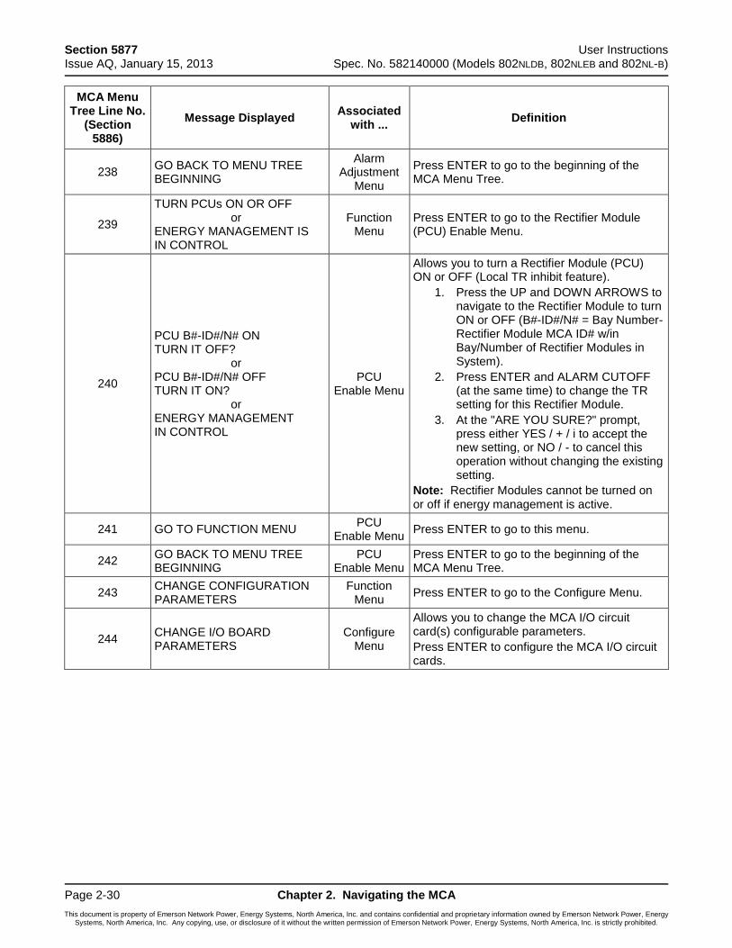
Section 5877 User Instructions Issue AQ, January 15, 2013 Spec. No. 582140000 (Models 802NLDB, 802NLEB and 802NL-B)
Page 2-30 Chapter 2. Navigating the MCA
This document is property of Emerson Network Power, Energy Systems, North America, Inc. and contains confidential and proprietary information owned by Emerson Network Power, Energy Systems, North America, Inc. Any copying, use, or disclosure of it without the written permission of Emerson Network Power, Energy Systems, North America, Inc. is strictly prohibited.
MCA Menu Tree Line No.
(Section 5886)
Message Displayed Associated
with ... Definition
238 GO BACK TO MENU TREE BEGINNING
Alarm Adjustment
Menu
Press ENTER to go to the beginning of the MCA Menu Tree.
239
TURN PCUs ON OR OFF or ENERGY MANAGEMENT IS IN CONTROL
Function Menu
Press ENTER to go to the Rectifier Module (PCU) Enable Menu.
240
PCU B#-ID#/N# ON TURN IT OFF? or PCU B#-ID#/N# OFF TURN IT ON? or ENERGY MANAGEMENT IN CONTROL
PCU Enable Menu
Allows you to turn a Rectifier Module (PCU) ON or OFF (Local TR inhibit feature).
1. Press the UP and DOWN ARROWS to navigate to the Rectifier Module to turn ON or OFF (B#-ID#/N# = Bay Number-Rectifier Module MCA ID# w/in Bay/Number of Rectifier Modules in System).
2. Press ENTER and ALARM CUTOFF (at the same time) to change the TR setting for this Rectifier Module.
3. At the "ARE YOU SURE?" prompt, press either YES / + / i to accept the new setting, or NO / - to cancel this operation without changing the existing setting.
Note: Rectifier Modules cannot be turned on or off if energy management is active.
241 GO TO FUNCTION MENU PCU
Enable Menu Press ENTER to go to this menu.
242 GO BACK TO MENU TREE BEGINNING
PCU Enable Menu
Press ENTER to go to the beginning of the MCA Menu Tree.
243 CHANGE CONFIGURATION PARAMETERS
Function Menu
Press ENTER to go to the Configure Menu.
244 CHANGE I/O BOARD PARAMETERS
Configure Menu
Allows you to change the MCA I/O circuit card(s) configurable parameters.
Press ENTER to configure the MCA I/O circuit cards.
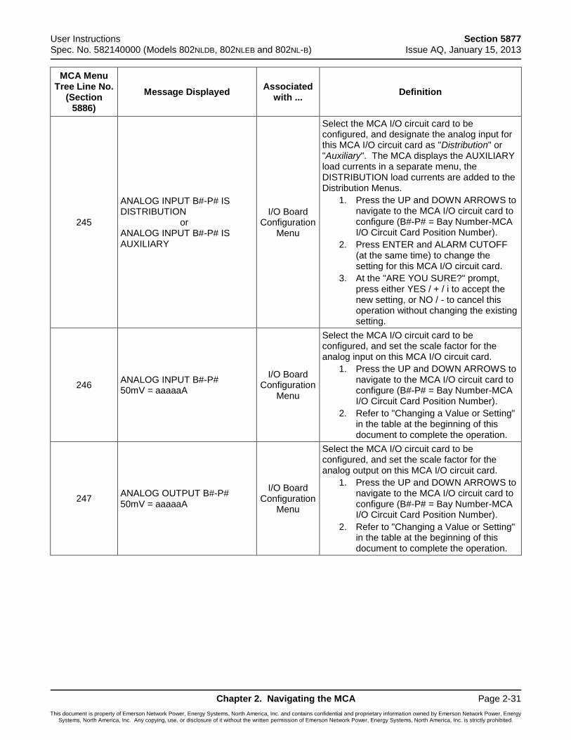
User Instructions Section 5877 Spec. No. 582140000 (Models 802NLDB, 802NLEB and 802NL-B) Issue AQ, January 15, 2013
Chapter 2. Navigating the MCA Page 2-31
This document is property of Emerson Network Power, Energy Systems, North America, Inc. and contains confidential and proprietary information owned by Emerson Network Power, Energy Systems, North America, Inc. Any copying, use, or disclosure of it without the written permission of Emerson Network Power, Energy Systems, North America, Inc. is strictly prohibited.
MCA Menu Tree Line No.
(Section 5886)
Message Displayed Associated
with ... Definition
245
ANALOG INPUT B#-P# IS DISTRIBUTION or ANALOG INPUT B#-P# IS AUXILIARY
I/O Board Configuration
Menu
Select the MCA I/O circuit card to be configured, and designate the analog input for this MCA I/O circuit card as "Distribution" or "Auxiliary". The MCA displays the AUXILIARY load currents in a separate menu, the DISTRIBUTION load currents are added to the Distribution Menus.
1. Press the UP and DOWN ARROWS to navigate to the MCA I/O circuit card to configure (B#-P# = Bay Number-MCA I/O Circuit Card Position Number).
2. Press ENTER and ALARM CUTOFF (at the same time) to change the setting for this MCA I/O circuit card.
3. At the "ARE YOU SURE?" prompt, press either YES / + / i to accept the new setting, or NO / - to cancel this operation without changing the existing setting.
246 ANALOG INPUT B#-P# 50mV = aaaaaA
I/O Board Configuration
Menu
Select the MCA I/O circuit card to be configured, and set the scale factor for the analog input on this MCA I/O circuit card.
1. Press the UP and DOWN ARROWS to navigate to the MCA I/O circuit card to configure (B#-P# = Bay Number-MCA I/O Circuit Card Position Number).
2. Refer to "Changing a Value or Setting" in the table at the beginning of this document to complete the operation.
247 ANALOG OUTPUT B#-P# 50mV = aaaaaA
I/O Board Configuration
Menu
Select the MCA I/O circuit card to be configured, and set the scale factor for the analog output on this MCA I/O circuit card.
1. Press the UP and DOWN ARROWS to navigate to the MCA I/O circuit card to configure (B#-P# = Bay Number-MCA I/O Circuit Card Position Number).
2. Refer to "Changing a Value or Setting" in the table at the beginning of this document to complete the operation.
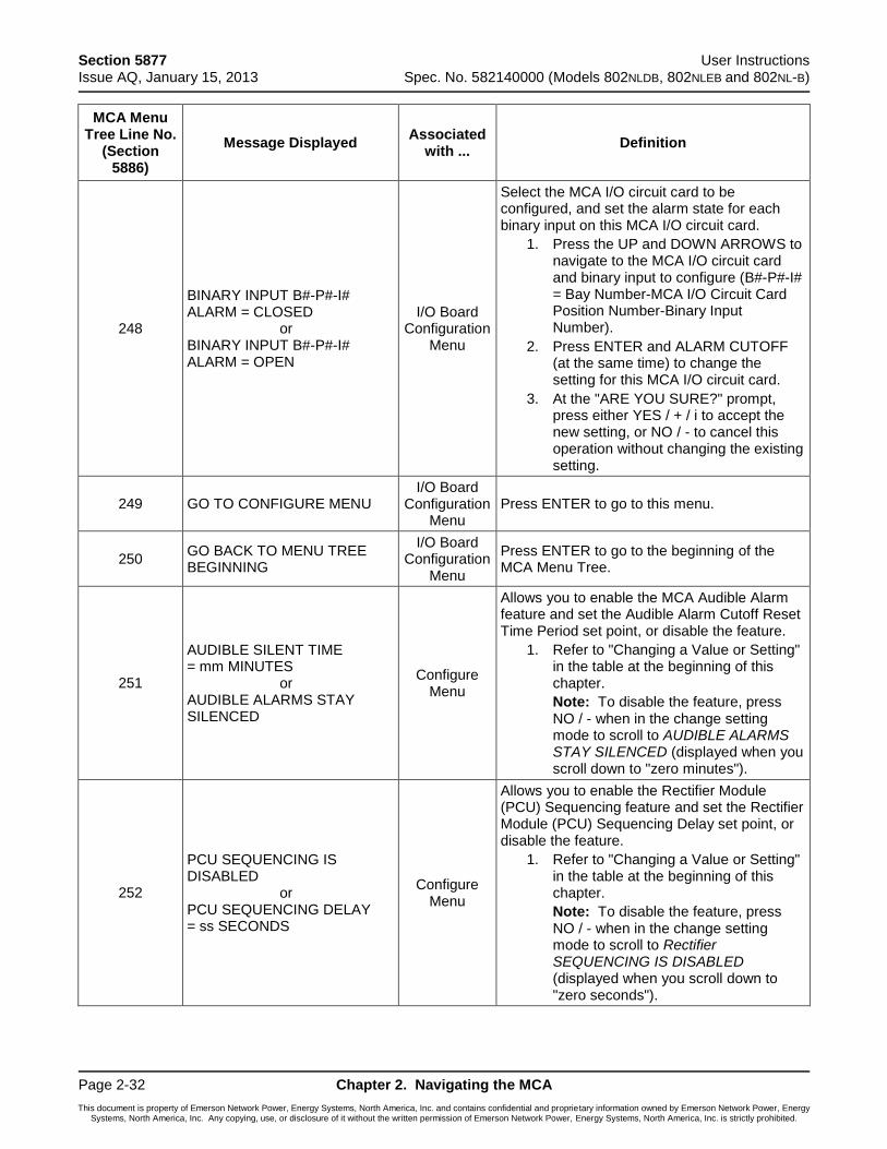
Section 5877 User Instructions Issue AQ, January 15, 2013 Spec. No. 582140000 (Models 802NLDB, 802NLEB and 802NL-B)
Page 2-32 Chapter 2. Navigating the MCA
This document is property of Emerson Network Power, Energy Systems, North America, Inc. and contains confidential and proprietary information owned by Emerson Network Power, Energy Systems, North America, Inc. Any copying, use, or disclosure of it without the written permission of Emerson Network Power, Energy Systems, North America, Inc. is strictly prohibited.
MCA Menu Tree Line No.
(Section 5886)
Message Displayed Associated
with ... Definition
248
BINARY INPUT B#-P#-I# ALARM = CLOSED or BINARY INPUT B#-P#-I# ALARM = OPEN
I/O Board Configuration
Menu
Select the MCA I/O circuit card to be configured, and set the alarm state for each binary input on this MCA I/O circuit card.
1. Press the UP and DOWN ARROWS to navigate to the MCA I/O circuit card and binary input to configure (B#-P#-I# = Bay Number-MCA I/O Circuit Card Position Number-Binary Input Number).
2. Press ENTER and ALARM CUTOFF (at the same time) to change the setting for this MCA I/O circuit card.
3. At the "ARE YOU SURE?" prompt, press either YES / + / i to accept the new setting, or NO / - to cancel this operation without changing the existing setting.
249 GO TO CONFIGURE MENU I/O Board
Configuration Menu
Press ENTER to go to this menu.
250 GO BACK TO MENU TREE BEGINNING
I/O Board Configuration
Menu
Press ENTER to go to the beginning of the MCA Menu Tree.
251
AUDIBLE SILENT TIME = mm MINUTES or AUDIBLE ALARMS STAY SILENCED
Configure Menu
Allows you to enable the MCA Audible Alarm feature and set the Audible Alarm Cutoff Reset Time Period set point, or disable the feature.
1. Refer to "Changing a Value or Setting" in the table at the beginning of this chapter.
Note: To disable the feature, press NO / - when in the change setting mode to scroll to AUDIBLE ALARMS STAY SILENCED (displayed when you scroll down to "zero minutes").
252
PCU SEQUENCING IS DISABLED or PCU SEQUENCING DELAY = ss SECONDS
Configure Menu
Allows you to enable the Rectifier Module (PCU) Sequencing feature and set the Rectifier Module (PCU) Sequencing Delay set point, or disable the feature.
1. Refer to "Changing a Value or Setting" in the table at the beginning of this chapter.
Note: To disable the feature, press NO / - when in the change setting mode to scroll to Rectifier SEQUENCING IS DISABLED (displayed when you scroll down to "zero seconds").
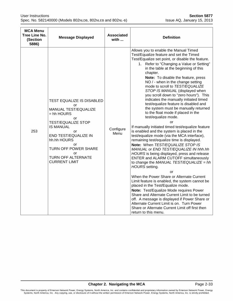
User Instructions Section 5877 Spec. No. 582140000 (Models 802NLDB, 802NLEB and 802NL-B) Issue AQ, January 15, 2013
Chapter 2. Navigating the MCA Page 2-33
This document is property of Emerson Network Power, Energy Systems, North America, Inc. and contains confidential and proprietary information owned by Emerson Network Power, Energy Systems, North America, Inc. Any copying, use, or disclosure of it without the written permission of Emerson Network Power, Energy Systems, North America, Inc. is strictly prohibited.
MCA Menu Tree Line No.
(Section 5886)
Message Displayed Associated
with ... Definition
253
TEST EQUALIZE IS DISABLED or MANUAL TEST/EQUALIZE = hh HOURS or TEST/EQUALIZE STOP IS MANUAL or END TEST/EQUALIZE IN hh.hh HOURS or TURN OFF POWER SHARE or TURN OFF ALTERNATE CURRENT LIMIT
Configure Menu
Allows you to enable the Manual Timed Test/Equalize feature and set the Timed Test/Equalize set point, or disable the feature.
1. Refer to "Changing a Value or Setting" in the table at the beginning of this chapter.
Note: To disable the feature, press NO / - when in the change setting mode to scroll to TEST/EQUALIZE STOP IS MANUAL (displayed when you scroll down to "zero hours"). This indicates the manually initiated timed test/equalize feature is disabled and the system must be manually returned to the float mode if placed in the test/equalize mode.
or
If manually initiated timed test/equalize feature is enabled and the system is placed in the test/equalize mode (via the MCA interface), remaining test/equalize time is displayed.
Note: When TEST/EQUALIZE STOP IS MANUAL or END TEST/EQUALIZE IN hhh.hh HOURS is being displayed, press and release ENTER and ALARM CUTOFF simultaneously to change the MANUAL TEST/EQUALIZE = hh HOURS setting.
or
When the Power Share or Alternate Current Limit feature is enabled, the system cannot be placed in the Test/Equalize mode.
Note: Test/Equalize Mode requires Power Share and Alternate Current Limit to be turned off. A message is displayed if Power Share or Alternate Current Limit is on. Turn Power Share or Alternate Current Limit off first then return to this menu.
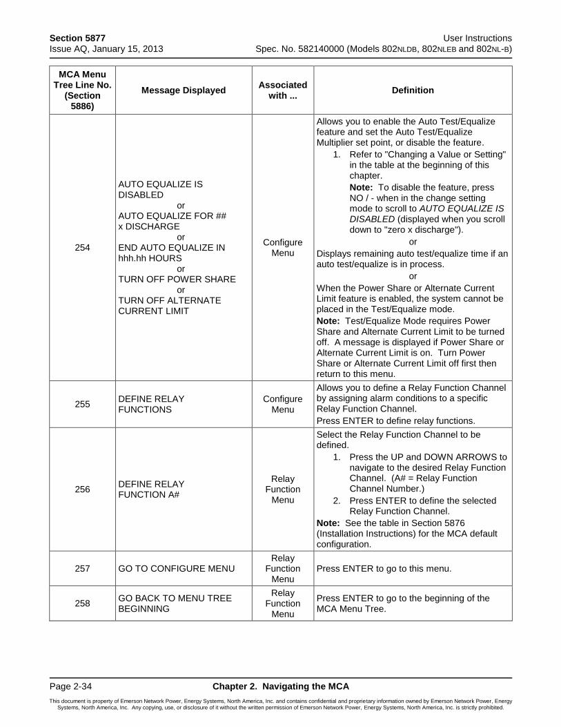
Section 5877 User Instructions Issue AQ, January 15, 2013 Spec. No. 582140000 (Models 802NLDB, 802NLEB and 802NL-B)
Page 2-34 Chapter 2. Navigating the MCA
This document is property of Emerson Network Power, Energy Systems, North America, Inc. and contains confidential and proprietary information owned by Emerson Network Power, Energy Systems, North America, Inc. Any copying, use, or disclosure of it without the written permission of Emerson Network Power, Energy Systems, North America, Inc. is strictly prohibited.
MCA Menu Tree Line No.
(Section 5886)
Message Displayed Associated
with ... Definition
254
AUTO EQUALIZE IS DISABLED or AUTO EQUALIZE FOR ## x DISCHARGE or END AUTO EQUALIZE IN hhh.hh HOURS or TURN OFF POWER SHARE or TURN OFF ALTERNATE CURRENT LIMIT
Configure Menu
Allows you to enable the Auto Test/Equalize feature and set the Auto Test/Equalize Multiplier set point, or disable the feature.
1. Refer to "Changing a Value or Setting" in the table at the beginning of this chapter.
Note: To disable the feature, press NO / - when in the change setting mode to scroll to AUTO EQUALIZE IS DISABLED (displayed when you scroll down to "zero x discharge").
or
Displays remaining auto test/equalize time if an auto test/equalize is in process.
or
When the Power Share or Alternate Current Limit feature is enabled, the system cannot be placed in the Test/Equalize mode.
Note: Test/Equalize Mode requires Power Share and Alternate Current Limit to be turned off. A message is displayed if Power Share or Alternate Current Limit is on. Turn Power Share or Alternate Current Limit off first then return to this menu.
255 DEFINE RELAY FUNCTIONS
Configure Menu
Allows you to define a Relay Function Channel by assigning alarm conditions to a specific Relay Function Channel.
Press ENTER to define relay functions.
256 DEFINE RELAY FUNCTION A#
Relay Function
Menu
Select the Relay Function Channel to be defined.
1. Press the UP and DOWN ARROWS to navigate to the desired Relay Function Channel. (A# = Relay Function Channel Number.)
2. Press ENTER to define the selected Relay Function Channel.
Note: See the table in Section 5876 (Installation Instructions) for the MCA default configuration.
257 GO TO CONFIGURE MENU Relay
Function Menu
Press ENTER to go to this menu.
258 GO BACK TO MENU TREE BEGINNING
Relay Function
Menu
Press ENTER to go to the beginning of the MCA Menu Tree.
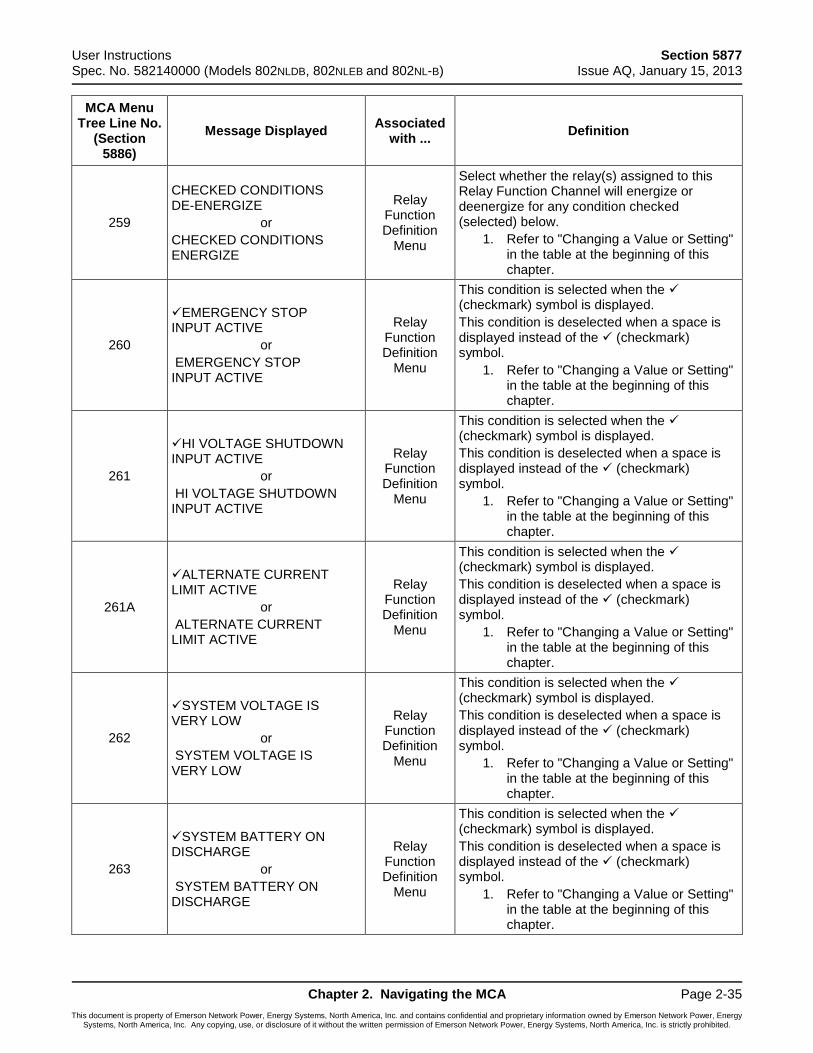
User Instructions Section 5877 Spec. No. 582140000 (Models 802NLDB, 802NLEB and 802NL-B) Issue AQ, January 15, 2013
Chapter 2. Navigating the MCA Page 2-35
This document is property of Emerson Network Power, Energy Systems, North America, Inc. and contains confidential and proprietary information owned by Emerson Network Power, Energy Systems, North America, Inc. Any copying, use, or disclosure of it without the written permission of Emerson Network Power, Energy Systems, North America, Inc. is strictly prohibited.
MCA Menu Tree Line No.
(Section 5886)
Message Displayed Associated
with ... Definition
259
CHECKED CONDITIONS DE-ENERGIZE
or
CHECKED CONDITIONS ENERGIZE
Relay Function Definition
Menu
Select whether the relay(s) assigned to this Relay Function Channel will energize or deenergize for any condition checked (selected) below.
1. Refer to "Changing a Value or Setting" in the table at the beginning of this chapter.
260
EMERGENCY STOP INPUT ACTIVE
or
EMERGENCY STOP INPUT ACTIVE
Relay Function Definition
Menu
This condition is selected when the (checkmark) symbol is displayed.
This condition is deselected when a space is displayed instead of the (checkmark) symbol.
1. Refer to "Changing a Value or Setting" in the table at the beginning of this chapter.
261
HI VOLTAGE SHUTDOWN INPUT ACTIVE
or
HI VOLTAGE SHUTDOWN INPUT ACTIVE
Relay Function Definition
Menu
This condition is selected when the (checkmark) symbol is displayed.
This condition is deselected when a space is displayed instead of the (checkmark) symbol.
1. Refer to "Changing a Value or Setting" in the table at the beginning of this chapter.
261A
ALTERNATE CURRENT LIMIT ACTIVE
or
ALTERNATE CURRENT LIMIT ACTIVE
Relay Function Definition
Menu
This condition is selected when the (checkmark) symbol is displayed.
This condition is deselected when a space is displayed instead of the (checkmark) symbol.
1. Refer to "Changing a Value or Setting" in the table at the beginning of this chapter.
262
SYSTEM VOLTAGE IS VERY LOW
or
SYSTEM VOLTAGE IS VERY LOW
Relay Function Definition
Menu
This condition is selected when the (checkmark) symbol is displayed.
This condition is deselected when a space is displayed instead of the (checkmark) symbol.
1. Refer to "Changing a Value or Setting" in the table at the beginning of this chapter.
263
SYSTEM BATTERY ON DISCHARGE
or
SYSTEM BATTERY ON DISCHARGE
Relay Function Definition
Menu
This condition is selected when the (checkmark) symbol is displayed.
This condition is deselected when a space is displayed instead of the (checkmark) symbol.
1. Refer to "Changing a Value or Setting" in the table at the beginning of this chapter.

Section 5877 User Instructions Issue AQ, January 15, 2013 Spec. No. 582140000 (Models 802NLDB, 802NLEB and 802NL-B)
Page 2-36 Chapter 2. Navigating the MCA
This document is property of Emerson Network Power, Energy Systems, North America, Inc. and contains confidential and proprietary information owned by Emerson Network Power, Energy Systems, North America, Inc. Any copying, use, or disclosure of it without the written permission of Emerson Network Power, Energy Systems, North America, Inc. is strictly prohibited.
MCA Menu Tree Line No.
(Section 5886)
Message Displayed Associated
with ... Definition
264
SYSTEM HIGH VOLTAGE #1 ALARM
or
SYSTEM HIGH VOLTAGE #1 ALARM
Relay Function Definition
Menu
This condition is selected when the (checkmark) symbol is displayed.
This condition is deselected when a space is displayed instead of the (checkmark) symbol.
1. Refer to "Changing a Value or Setting" in the table at the beginning of this chapter.
265
SYSTEM HIGH VOLTAGE #2 ALARM
or
SYSTEM HIGH VOLTAGE #2 ALARM
Relay Function Definition
Menu
This condition is selected when the (checkmark) symbol is displayed.
This condition is deselected when a space is displayed instead of the (checkmark) symbol.
1. Refer to "Changing a Value or Setting" in the table at the beginning of this chapter.
266
1 SYSTEM BREAKER OR FUSE ALARM
or
1 SYSTEM BREAKER OR FUSE ALARM
Relay Function Definition
Menu
This condition is selected when the (checkmark) symbol is displayed.
This condition is deselected when a space is displayed instead of the (checkmark) symbol.
1. Refer to "Changing a Value or Setting" in the table at the beginning of this chapter.
267
2+ SYSTEM BREAKER & FUSE ALARMS
or
2+ SYSTEM BREAKER & FUSE ALARMS
Relay Function Definition
Menu
This condition is selected when the (checkmark) symbol is displayed.
This condition is deselected when a space is displayed instead of the (checkmark) symbol.
1. Refer to "Changing a Value or Setting" in the table at the beginning of this chapter.
268
AC POWER IS OFF TO 1 PCU
or
AC POWER IS OFF TO 1 PCU
Relay Function Definition
Menu
This condition is selected when the (checkmark) symbol is displayed.
This condition is deselected when a space is displayed instead of the (checkmark) symbol.
1. Refer to "Changing a Value or Setting" in the table at the beginning of this chapter.
269
AC POWER IS OFF TO 2+ PCUs
or
AC POWER IS OFF TO 2+ PCUs
Relay Function Definition
Menu
This condition is selected when the (checkmark) symbol is displayed.
This condition is deselected when a space is displayed instead of the (checkmark) symbol.
1. Refer to "Changing a Value or Setting" in the table at the beginning of this chapter.
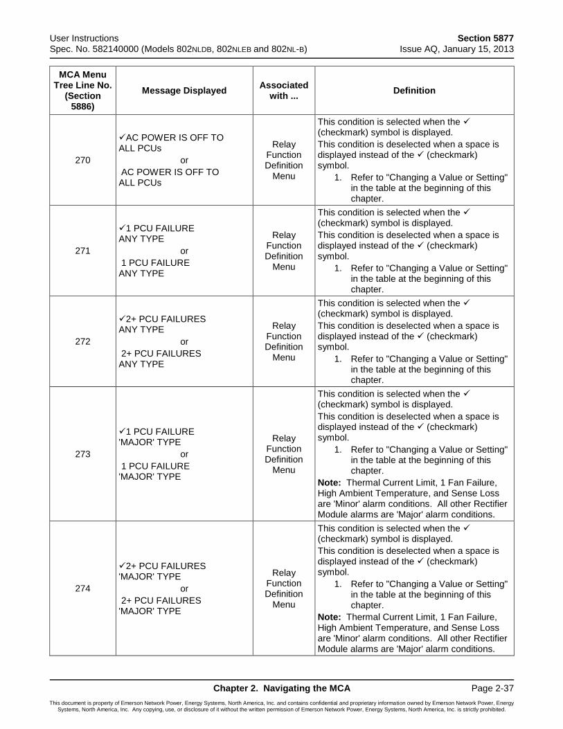
User Instructions Section 5877 Spec. No. 582140000 (Models 802NLDB, 802NLEB and 802NL-B) Issue AQ, January 15, 2013
Chapter 2. Navigating the MCA Page 2-37
This document is property of Emerson Network Power, Energy Systems, North America, Inc. and contains confidential and proprietary information owned by Emerson Network Power, Energy Systems, North America, Inc. Any copying, use, or disclosure of it without the written permission of Emerson Network Power, Energy Systems, North America, Inc. is strictly prohibited.
MCA Menu Tree Line No.
(Section 5886)
Message Displayed Associated
with ... Definition
270
AC POWER IS OFF TO ALL PCUs
or
AC POWER IS OFF TO ALL PCUs
Relay Function Definition
Menu
This condition is selected when the (checkmark) symbol is displayed.
This condition is deselected when a space is displayed instead of the (checkmark) symbol.
1. Refer to "Changing a Value or Setting" in the table at the beginning of this chapter.
271
1 PCU FAILURE ANY TYPE
or
1 PCU FAILURE ANY TYPE
Relay Function Definition
Menu
This condition is selected when the (checkmark) symbol is displayed.
This condition is deselected when a space is displayed instead of the (checkmark) symbol.
1. Refer to "Changing a Value or Setting" in the table at the beginning of this chapter.
272
2+ PCU FAILURES ANY TYPE
or
2+ PCU FAILURES ANY TYPE
Relay Function Definition
Menu
This condition is selected when the (checkmark) symbol is displayed.
This condition is deselected when a space is displayed instead of the (checkmark) symbol.
1. Refer to "Changing a Value or Setting" in the table at the beginning of this chapter.
273
1 PCU FAILURE 'MAJOR' TYPE
or
1 PCU FAILURE 'MAJOR' TYPE
Relay Function Definition
Menu
This condition is selected when the (checkmark) symbol is displayed.
This condition is deselected when a space is displayed instead of the (checkmark) symbol.
1. Refer to "Changing a Value or Setting" in the table at the beginning of this chapter.
Note: Thermal Current Limit, 1 Fan Failure, High Ambient Temperature, and Sense Loss are 'Minor' alarm conditions. All other Rectifier Module alarms are 'Major' alarm conditions.
274
2+ PCU FAILURES 'MAJOR' TYPE
or
2+ PCU FAILURES 'MAJOR' TYPE
Relay Function Definition
Menu
This condition is selected when the (checkmark) symbol is displayed.
This condition is deselected when a space is displayed instead of the (checkmark) symbol.
1. Refer to "Changing a Value or Setting" in the table at the beginning of this chapter.
Note: Thermal Current Limit, 1 Fan Failure, High Ambient Temperature, and Sense Loss are 'Minor' alarm conditions. All other Rectifier Module alarms are 'Major' alarm conditions.

Section 5877 User Instructions Issue AQ, January 15, 2013 Spec. No. 582140000 (Models 802NLDB, 802NLEB and 802NL-B)
Page 2-38 Chapter 2. Navigating the MCA
This document is property of Emerson Network Power, Energy Systems, North America, Inc. and contains confidential and proprietary information owned by Emerson Network Power, Energy Systems, North America, Inc. Any copying, use, or disclosure of it without the written permission of Emerson Network Power, Energy Systems, North America, Inc. is strictly prohibited.
MCA Menu Tree Line No.
(Section 5886)
Message Displayed Associated
with ... Definition
275
1 PCU FAILURE 'MINOR' TYPE
or
1 PCU FAILURE 'MINOR' TYPE
Relay Function Definition
Menu
This condition is selected when the (checkmark) symbol is displayed.
This condition is deselected when a space is displayed instead of the (checkmark) symbol.
1. Refer to "Changing a Value or Setting" in the table at the beginning of this chapter.
Note: Thermal Current Limit, 1 Fan Failure, High Ambient Temperature, and Sense Loss are 'Minor' alarm conditions. All other Rectifier Module alarms are 'Major' alarm conditions.
276
2+ PCU FAILURES 'MINOR' TYPE
or
2+ PCU FAILURES 'MINOR' TYPE
Relay Function Definition
Menu
This condition is selected when the (checkmark) symbol is displayed.
This condition is deselected when a space is displayed instead of the (checkmark) symbol.
1. Refer to "Changing a Value or Setting" in the table at the beginning of this chapter.
Note: Thermal Current Limit, 1 Fan Failure, High Ambient Temperature, and Sense Loss are 'Minor' alarm conditions. All other Rectifier Module alarms are 'Major' alarm conditions.
277
NO PCUs ARE IN INVENTORY
or
NO PCUs ARE IN INVENTORY
Relay Function Definition
Menu
This condition is selected when the (checkmark) symbol is displayed.
This condition is deselected when a space is displayed instead of the (checkmark) symbol.
1. Refer to "Changing a Value or Setting" in the table at the beginning of this chapter.
278
1 DIST. PANEL FAILURE
or
1 DIST. PANEL FAILURE
Relay Function Definition
Menu
This condition is selected when the (checkmark) symbol is displayed.
This condition is deselected when a space is displayed instead of the (checkmark) symbol.
1. Refer to "Changing a Value or Setting" in the table at the beginning of this chapter.
279
2+ DIST. PANEL FAILURES
or
2+ DIST. PANEL FAILURES
Relay Function Definition
Menu
This condition is selected when the (checkmark) symbol is displayed.
This condition is deselected when a space is displayed instead of the (checkmark) symbol.
1. Refer to "Changing a Value or Setting" in the table at the beginning of this chapter.
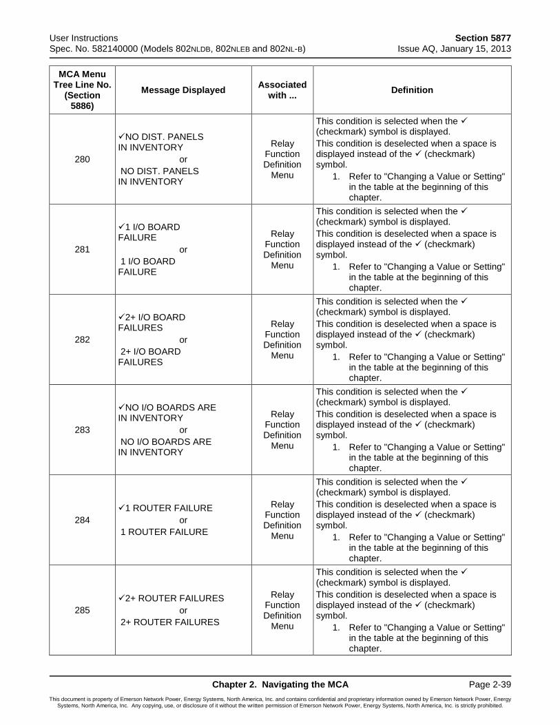
User Instructions Section 5877 Spec. No. 582140000 (Models 802NLDB, 802NLEB and 802NL-B) Issue AQ, January 15, 2013
Chapter 2. Navigating the MCA Page 2-39
This document is property of Emerson Network Power, Energy Systems, North America, Inc. and contains confidential and proprietary information owned by Emerson Network Power, Energy Systems, North America, Inc. Any copying, use, or disclosure of it without the written permission of Emerson Network Power, Energy Systems, North America, Inc. is strictly prohibited.
MCA Menu Tree Line No.
(Section 5886)
Message Displayed Associated
with ... Definition
280
NO DIST. PANELS IN INVENTORY
or
NO DIST. PANELS IN INVENTORY
Relay Function Definition
Menu
This condition is selected when the (checkmark) symbol is displayed.
This condition is deselected when a space is displayed instead of the (checkmark) symbol.
1. Refer to "Changing a Value or Setting" in the table at the beginning of this chapter.
281
1 I/O BOARD FAILURE
or
1 I/O BOARD FAILURE
Relay Function Definition
Menu
This condition is selected when the (checkmark) symbol is displayed.
This condition is deselected when a space is displayed instead of the (checkmark) symbol.
1. Refer to "Changing a Value or Setting" in the table at the beginning of this chapter.
282
2+ I/O BOARD FAILURES
or
2+ I/O BOARD FAILURES
Relay Function Definition
Menu
This condition is selected when the (checkmark) symbol is displayed.
This condition is deselected when a space is displayed instead of the (checkmark) symbol.
1. Refer to "Changing a Value or Setting" in the table at the beginning of this chapter.
283
NO I/O BOARDS ARE IN INVENTORY
or
NO I/O BOARDS ARE IN INVENTORY
Relay Function Definition
Menu
This condition is selected when the (checkmark) symbol is displayed.
This condition is deselected when a space is displayed instead of the (checkmark) symbol.
1. Refer to "Changing a Value or Setting" in the table at the beginning of this chapter.
284
1 ROUTER FAILURE
or
1 ROUTER FAILURE
Relay Function Definition
Menu
This condition is selected when the (checkmark) symbol is displayed.
This condition is deselected when a space is displayed instead of the (checkmark) symbol.
1. Refer to "Changing a Value or Setting" in the table at the beginning of this chapter.
285
2+ ROUTER FAILURES
or
2+ ROUTER FAILURES
Relay Function Definition
Menu
This condition is selected when the (checkmark) symbol is displayed.
This condition is deselected when a space is displayed instead of the (checkmark) symbol.
1. Refer to "Changing a Value or Setting" in the table at the beginning of this chapter.
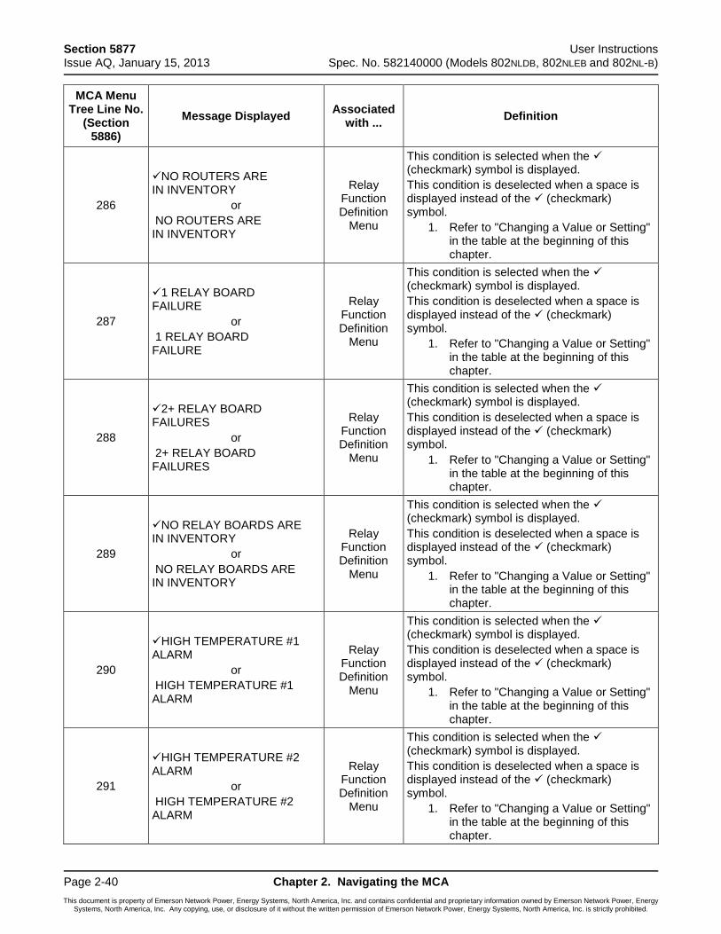
Section 5877 User Instructions Issue AQ, January 15, 2013 Spec. No. 582140000 (Models 802NLDB, 802NLEB and 802NL-B)
Page 2-40 Chapter 2. Navigating the MCA
This document is property of Emerson Network Power, Energy Systems, North America, Inc. and contains confidential and proprietary information owned by Emerson Network Power, Energy Systems, North America, Inc. Any copying, use, or disclosure of it without the written permission of Emerson Network Power, Energy Systems, North America, Inc. is strictly prohibited.
MCA Menu Tree Line No.
(Section 5886)
Message Displayed Associated
with ... Definition
286
NO ROUTERS ARE IN INVENTORY
or
NO ROUTERS ARE IN INVENTORY
Relay Function Definition
Menu
This condition is selected when the (checkmark) symbol is displayed.
This condition is deselected when a space is displayed instead of the (checkmark) symbol.
1. Refer to "Changing a Value or Setting" in the table at the beginning of this chapter.
287
1 RELAY BOARD FAILURE
or
1 RELAY BOARD FAILURE
Relay Function Definition
Menu
This condition is selected when the (checkmark) symbol is displayed.
This condition is deselected when a space is displayed instead of the (checkmark) symbol.
1. Refer to "Changing a Value or Setting" in the table at the beginning of this chapter.
288
2+ RELAY BOARD FAILURES
or
2+ RELAY BOARD FAILURES
Relay Function Definition
Menu
This condition is selected when the (checkmark) symbol is displayed.
This condition is deselected when a space is displayed instead of the (checkmark) symbol.
1. Refer to "Changing a Value or Setting" in the table at the beginning of this chapter.
289
NO RELAY BOARDS ARE IN INVENTORY
or
NO RELAY BOARDS ARE IN INVENTORY
Relay Function Definition
Menu
This condition is selected when the (checkmark) symbol is displayed.
This condition is deselected when a space is displayed instead of the (checkmark) symbol.
1. Refer to "Changing a Value or Setting" in the table at the beginning of this chapter.
290
HIGH TEMPERATURE #1 ALARM
or
HIGH TEMPERATURE #1 ALARM
Relay Function Definition
Menu
This condition is selected when the (checkmark) symbol is displayed.
This condition is deselected when a space is displayed instead of the (checkmark) symbol.
1. Refer to "Changing a Value or Setting" in the table at the beginning of this chapter.
291
HIGH TEMPERATURE #2 ALARM
or
HIGH TEMPERATURE #2 ALARM
Relay Function Definition
Menu
This condition is selected when the (checkmark) symbol is displayed.
This condition is deselected when a space is displayed instead of the (checkmark) symbol.
1. Refer to "Changing a Value or Setting" in the table at the beginning of this chapter.
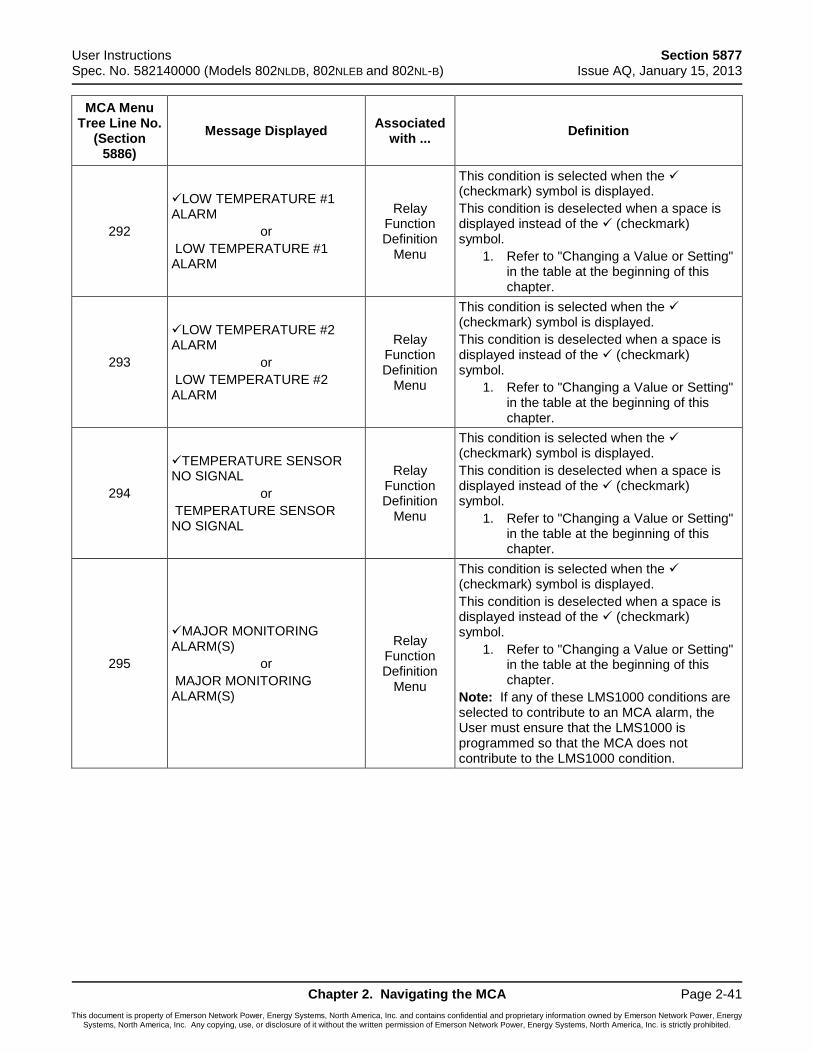
User Instructions Section 5877 Spec. No. 582140000 (Models 802NLDB, 802NLEB and 802NL-B) Issue AQ, January 15, 2013
Chapter 2. Navigating the MCA Page 2-41
This document is property of Emerson Network Power, Energy Systems, North America, Inc. and contains confidential and proprietary information owned by Emerson Network Power, Energy Systems, North America, Inc. Any copying, use, or disclosure of it without the written permission of Emerson Network Power, Energy Systems, North America, Inc. is strictly prohibited.
MCA Menu Tree Line No.
(Section 5886)
Message Displayed Associated
with ... Definition
292
LOW TEMPERATURE #1 ALARM
or
LOW TEMPERATURE #1 ALARM
Relay Function Definition
Menu
This condition is selected when the (checkmark) symbol is displayed.
This condition is deselected when a space is displayed instead of the (checkmark) symbol.
1. Refer to "Changing a Value or Setting" in the table at the beginning of this chapter.
293
LOW TEMPERATURE #2 ALARM
or
LOW TEMPERATURE #2 ALARM
Relay Function Definition
Menu
This condition is selected when the (checkmark) symbol is displayed.
This condition is deselected when a space is displayed instead of the (checkmark) symbol.
1. Refer to "Changing a Value or Setting" in the table at the beginning of this chapter.
294
TEMPERATURE SENSOR NO SIGNAL
or
TEMPERATURE SENSOR NO SIGNAL
Relay Function Definition
Menu
This condition is selected when the (checkmark) symbol is displayed.
This condition is deselected when a space is displayed instead of the (checkmark) symbol.
1. Refer to "Changing a Value or Setting" in the table at the beginning of this chapter.
295
MAJOR MONITORING ALARM(S)
or
MAJOR MONITORING ALARM(S)
Relay Function Definition
Menu
This condition is selected when the (checkmark) symbol is displayed.
This condition is deselected when a space is displayed instead of the (checkmark) symbol.
1. Refer to "Changing a Value or Setting" in the table at the beginning of this chapter.
Note: If any of these LMS1000 conditions are selected to contribute to an MCA alarm, the User must ensure that the LMS1000 is programmed so that the MCA does not contribute to the LMS1000 condition.
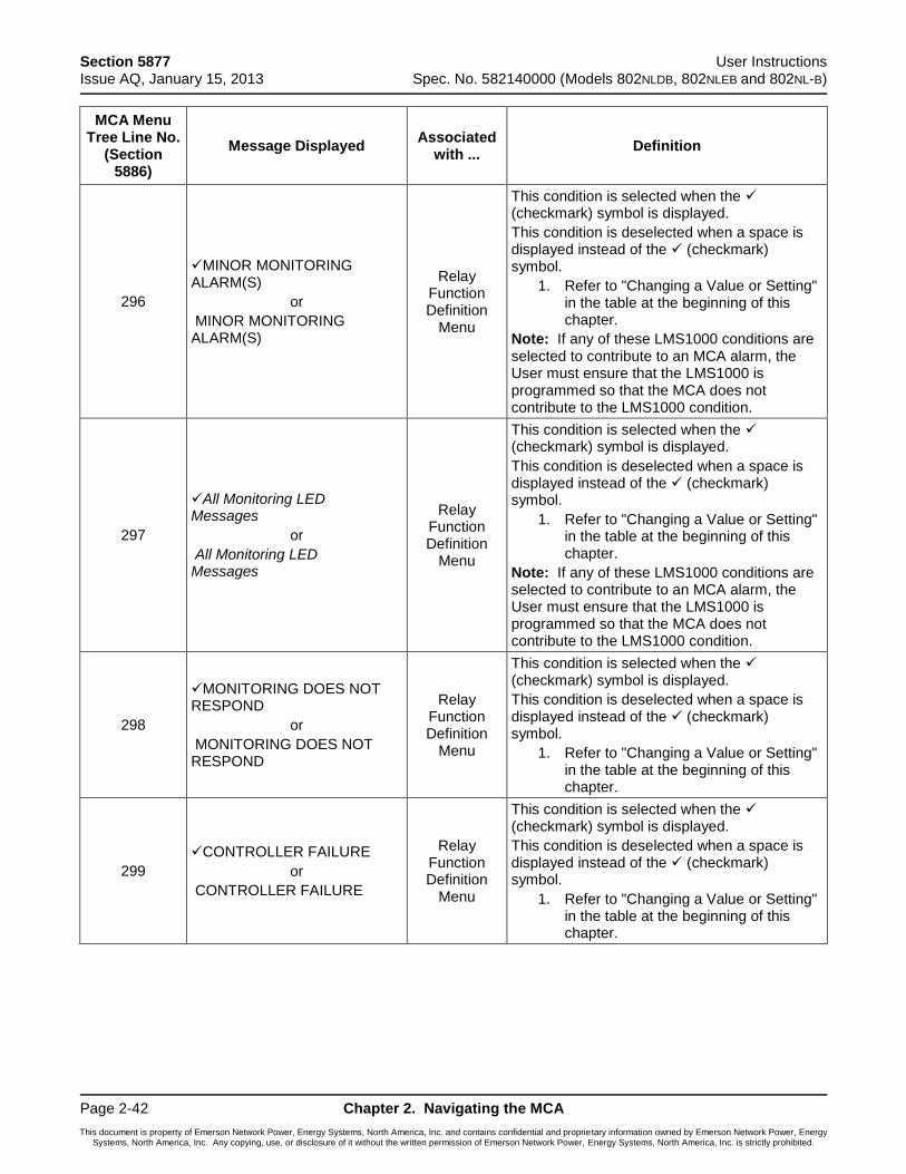
Section 5877 User Instructions Issue AQ, January 15, 2013 Spec. No. 582140000 (Models 802NLDB, 802NLEB and 802NL-B)
Page 2-42 Chapter 2. Navigating the MCA
This document is property of Emerson Network Power, Energy Systems, North America, Inc. and contains confidential and proprietary information owned by Emerson Network Power, Energy Systems, North America, Inc. Any copying, use, or disclosure of it without the written permission of Emerson Network Power, Energy Systems, North America, Inc. is strictly prohibited.
MCA Menu Tree Line No.
(Section 5886)
Message Displayed Associated
with ... Definition
296
MINOR MONITORING ALARM(S)
or
MINOR MONITORING ALARM(S)
Relay Function Definition
Menu
This condition is selected when the (checkmark) symbol is displayed.
This condition is deselected when a space is displayed instead of the (checkmark) symbol.
1. Refer to "Changing a Value or Setting" in the table at the beginning of this chapter.
Note: If any of these LMS1000 conditions are selected to contribute to an MCA alarm, the User must ensure that the LMS1000 is programmed so that the MCA does not contribute to the LMS1000 condition.
297
All Monitoring LED Messages
or
All Monitoring LED Messages
Relay Function Definition
Menu
This condition is selected when the (checkmark) symbol is displayed.
This condition is deselected when a space is displayed instead of the (checkmark) symbol.
1. Refer to "Changing a Value or Setting" in the table at the beginning of this chapter.
Note: If any of these LMS1000 conditions are selected to contribute to an MCA alarm, the User must ensure that the LMS1000 is programmed so that the MCA does not contribute to the LMS1000 condition.
298
MONITORING DOES NOT RESPOND
or
MONITORING DOES NOT RESPOND
Relay Function Definition
Menu
This condition is selected when the (checkmark) symbol is displayed.
This condition is deselected when a space is displayed instead of the (checkmark) symbol.
1. Refer to "Changing a Value or Setting" in the table at the beginning of this chapter.
299
CONTROLLER FAILURE
or
CONTROLLER FAILURE
Relay Function Definition
Menu
This condition is selected when the (checkmark) symbol is displayed.
This condition is deselected when a space is displayed instead of the (checkmark) symbol.
1. Refer to "Changing a Value or Setting" in the table at the beginning of this chapter.
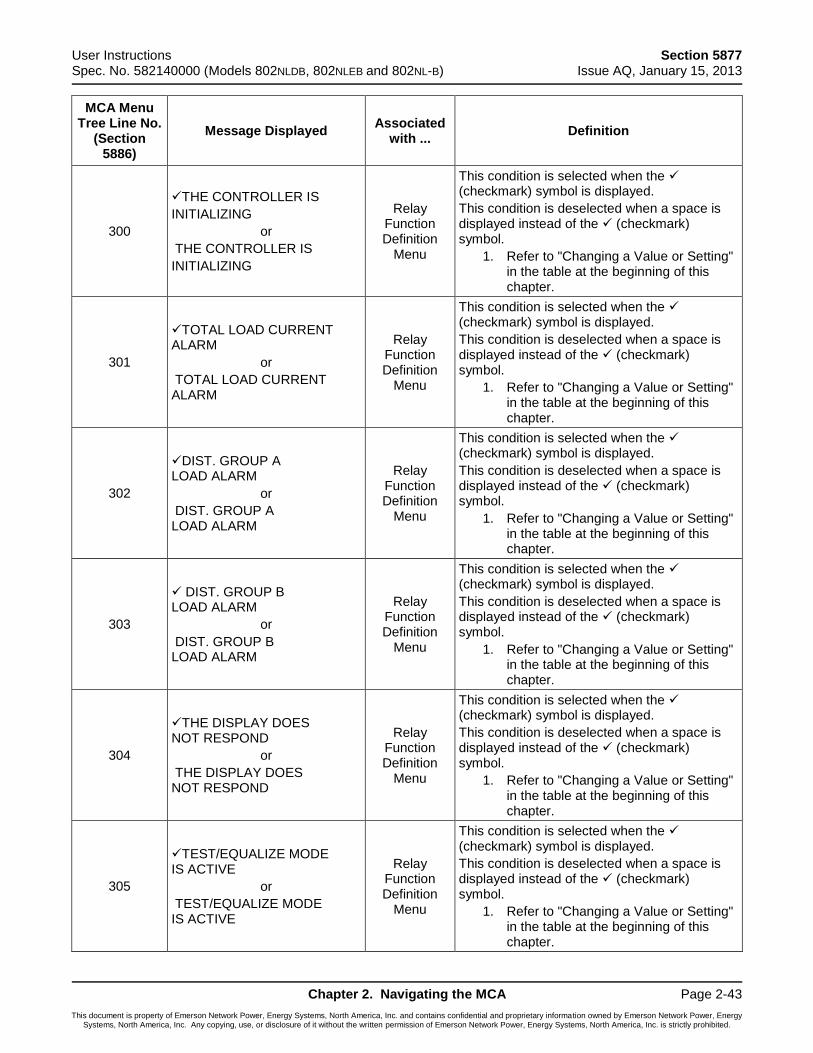
User Instructions Section 5877 Spec. No. 582140000 (Models 802NLDB, 802NLEB and 802NL-B) Issue AQ, January 15, 2013
Chapter 2. Navigating the MCA Page 2-43
This document is property of Emerson Network Power, Energy Systems, North America, Inc. and contains confidential and proprietary information owned by Emerson Network Power, Energy Systems, North America, Inc. Any copying, use, or disclosure of it without the written permission of Emerson Network Power, Energy Systems, North America, Inc. is strictly prohibited.
MCA Menu Tree Line No.
(Section 5886)
Message Displayed Associated
with ... Definition
300
THE CONTROLLER IS
INITIALIZING
or
THE CONTROLLER IS
INITIALIZING
Relay Function Definition
Menu
This condition is selected when the (checkmark) symbol is displayed.
This condition is deselected when a space is displayed instead of the (checkmark) symbol.
1. Refer to "Changing a Value or Setting" in the table at the beginning of this chapter.
301
TOTAL LOAD CURRENT ALARM
or
TOTAL LOAD CURRENT ALARM
Relay Function Definition
Menu
This condition is selected when the (checkmark) symbol is displayed.
This condition is deselected when a space is displayed instead of the (checkmark) symbol.
1. Refer to "Changing a Value or Setting" in the table at the beginning of this chapter.
302
DIST. GROUP A LOAD ALARM
or
DIST. GROUP A LOAD ALARM
Relay Function Definition
Menu
This condition is selected when the (checkmark) symbol is displayed.
This condition is deselected when a space is displayed instead of the (checkmark) symbol.
1. Refer to "Changing a Value or Setting" in the table at the beginning of this chapter.
303
DIST. GROUP B LOAD ALARM
or
DIST. GROUP B LOAD ALARM
Relay Function Definition
Menu
This condition is selected when the (checkmark) symbol is displayed.
This condition is deselected when a space is displayed instead of the (checkmark) symbol.
1. Refer to "Changing a Value or Setting" in the table at the beginning of this chapter.
304
THE DISPLAY DOES NOT RESPOND
or
THE DISPLAY DOES NOT RESPOND
Relay Function Definition
Menu
This condition is selected when the (checkmark) symbol is displayed.
This condition is deselected when a space is displayed instead of the (checkmark) symbol.
1. Refer to "Changing a Value or Setting" in the table at the beginning of this chapter.
305
TEST/EQUALIZE MODE IS ACTIVE
or
TEST/EQUALIZE MODE IS ACTIVE
Relay Function Definition
Menu
This condition is selected when the (checkmark) symbol is displayed.
This condition is deselected when a space is displayed instead of the (checkmark) symbol.
1. Refer to "Changing a Value or Setting" in the table at the beginning of this chapter.
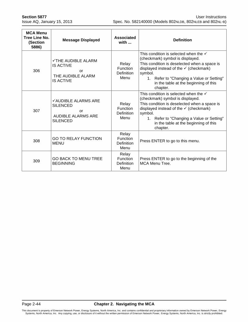
Section 5877 User Instructions Issue AQ, January 15, 2013 Spec. No. 582140000 (Models 802NLDB, 802NLEB and 802NL-B)
Page 2-44 Chapter 2. Navigating the MCA
This document is property of Emerson Network Power, Energy Systems, North America, Inc. and contains confidential and proprietary information owned by Emerson Network Power, Energy Systems, North America, Inc. Any copying, use, or disclosure of it without the written permission of Emerson Network Power, Energy Systems, North America, Inc. is strictly prohibited.
MCA Menu Tree Line No.
(Section 5886)
Message Displayed Associated
with ... Definition
306
THE AUDIBLE ALARM IS ACTIVE
or
THE AUDIBLE ALARM IS ACTIVE
Relay Function Definition
Menu
This condition is selected when the (checkmark) symbol is displayed.
This condition is deselected when a space is displayed instead of the (checkmark) symbol.
1. Refer to "Changing a Value or Setting" in the table at the beginning of this chapter.
307
AUDIBLE ALARMS ARE SILENCED
or
AUDIBLE ALARMS ARE SILENCED
Relay Function Definition
Menu
This condition is selected when the (checkmark) symbol is displayed.
This condition is deselected when a space is displayed instead of the (checkmark) symbol.
1. Refer to "Changing a Value or Setting" in the table at the beginning of this chapter.
308 GO TO RELAY FUNCTION MENU
Relay Function Definition
Menu
Press ENTER to go to this menu.
309 GO BACK TO MENU TREE BEGINNING
Relay Function Definition
Menu
Press ENTER to go to the beginning of the MCA Menu Tree.
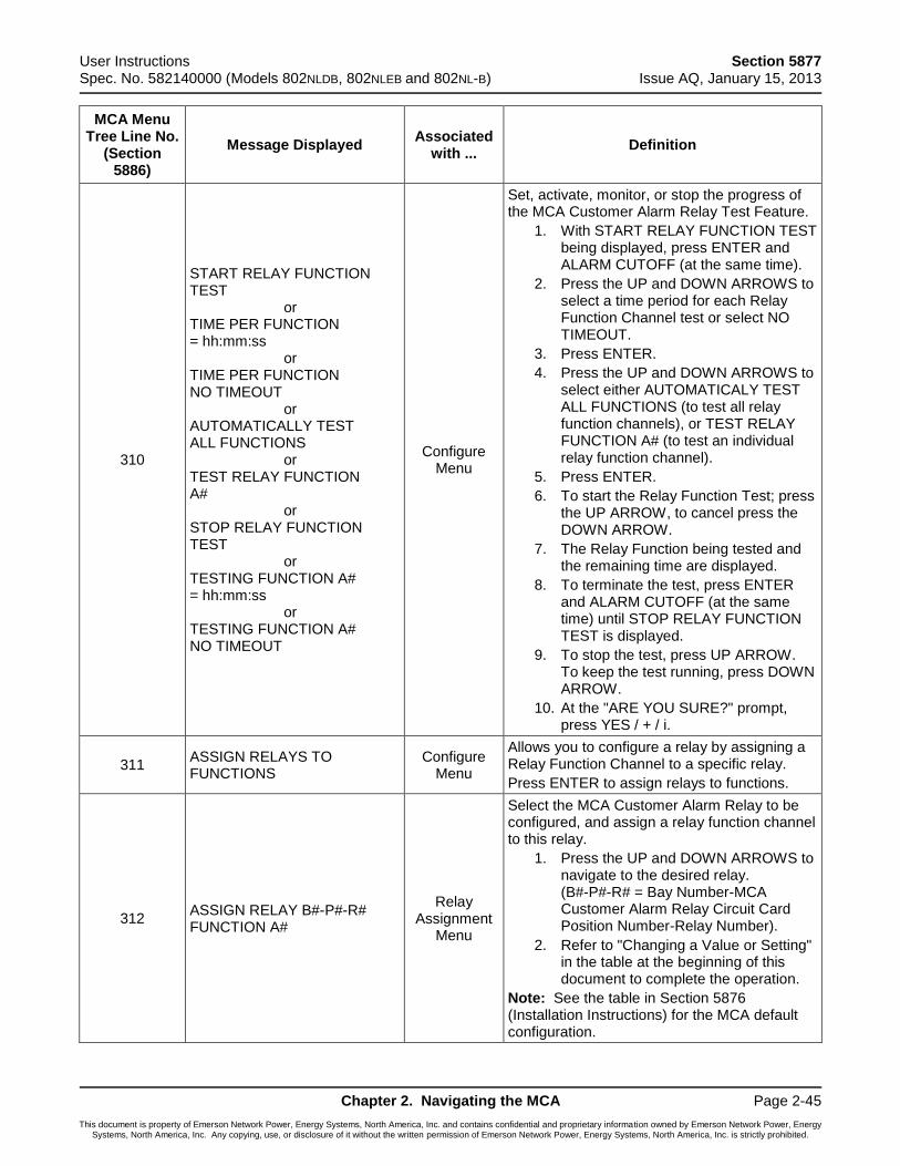
User Instructions Section 5877 Spec. No. 582140000 (Models 802NLDB, 802NLEB and 802NL-B) Issue AQ, January 15, 2013
Chapter 2. Navigating the MCA Page 2-45
This document is property of Emerson Network Power, Energy Systems, North America, Inc. and contains confidential and proprietary information owned by Emerson Network Power, Energy Systems, North America, Inc. Any copying, use, or disclosure of it without the written permission of Emerson Network Power, Energy Systems, North America, Inc. is strictly prohibited.
MCA Menu Tree Line No.
(Section 5886)
Message Displayed Associated
with ... Definition
310
START RELAY FUNCTION TEST or TIME PER FUNCTION = hh:mm:ss or TIME PER FUNCTION NO TIMEOUT or AUTOMATICALLY TEST ALL FUNCTIONS or TEST RELAY FUNCTION A# or STOP RELAY FUNCTION TEST or TESTING FUNCTION A# = hh:mm:ss or TESTING FUNCTION A# NO TIMEOUT
Configure Menu
Set, activate, monitor, or stop the progress of the MCA Customer Alarm Relay Test Feature.
1. With START RELAY FUNCTION TEST being displayed, press ENTER and ALARM CUTOFF (at the same time).
2. Press the UP and DOWN ARROWS to select a time period for each Relay Function Channel test or select NO TIMEOUT.
3. Press ENTER.
4. Press the UP and DOWN ARROWS to select either AUTOMATICALY TEST ALL FUNCTIONS (to test all relay function channels), or TEST RELAY FUNCTION A# (to test an individual relay function channel).
5. Press ENTER.
6. To start the Relay Function Test; press the UP ARROW, to cancel press the DOWN ARROW.
7. The Relay Function being tested and the remaining time are displayed.
8. To terminate the test, press ENTER and ALARM CUTOFF (at the same time) until STOP RELAY FUNCTION TEST is displayed.
9. To stop the test, press UP ARROW. To keep the test running, press DOWN ARROW.
10. At the "ARE YOU SURE?" prompt, press YES / + / i.
311 ASSIGN RELAYS TO FUNCTIONS
Configure Menu
Allows you to configure a relay by assigning a Relay Function Channel to a specific relay.
Press ENTER to assign relays to functions.
312 ASSIGN RELAY B#-P#-R# FUNCTION A#
Relay Assignment
Menu
Select the MCA Customer Alarm Relay to be configured, and assign a relay function channel to this relay.
1. Press the UP and DOWN ARROWS to navigate to the desired relay. (B#-P#-R# = Bay Number-MCA Customer Alarm Relay Circuit Card Position Number-Relay Number).
2. Refer to "Changing a Value or Setting" in the table at the beginning of this document to complete the operation.
Note: See the table in Section 5876 (Installation Instructions) for the MCA default configuration.
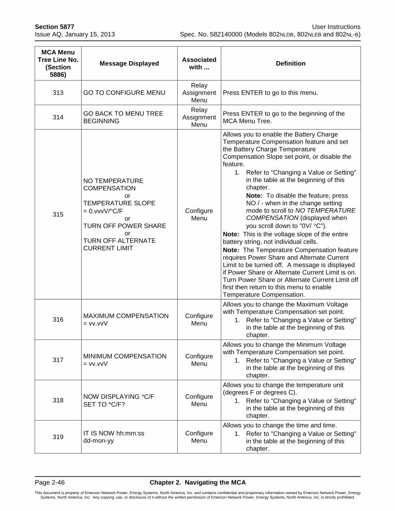
Section 5877 User Instructions Issue AQ, January 15, 2013 Spec. No. 582140000 (Models 802NLDB, 802NLEB and 802NL-B)
Page 2-46 Chapter 2. Navigating the MCA
This document is property of Emerson Network Power, Energy Systems, North America, Inc. and contains confidential and proprietary information owned by Emerson Network Power, Energy Systems, North America, Inc. Any copying, use, or disclosure of it without the written permission of Emerson Network Power, Energy Systems, North America, Inc. is strictly prohibited.
MCA Menu Tree Line No.
(Section 5886)
Message Displayed Associated
with ... Definition
313 GO TO CONFIGURE MENU Relay
Assignment Menu
Press ENTER to go to this menu.
314 GO BACK TO MENU TREE BEGINNING
Relay Assignment
Menu
Press ENTER to go to the beginning of the MCA Menu Tree.
315
NO TEMPERATURE COMPENSATION or TEMPERATURE SLOPE
= 0.vvvV/ C/F or TURN OFF POWER SHARE or TURN OFF ALTERNATE CURRENT LIMIT
Configure Menu
Allows you to enable the Battery Charge Temperature Compensation feature and set the Battery Charge Temperature Compensation Slope set point, or disable the feature.
1. Refer to "Changing a Value or Setting" in the table at the beginning of this chapter.
Note: To disable the feature, press NO / - when in the change setting mode to scroll to NO TEMPERATURE COMPENSATION (displayed when
you scroll down to "0V/ C").
Note: This is the voltage slope of the entire battery string, not individual cells.
Note: The Temperature Compensation feature requires Power Share and Alternate Current Limit to be turned off. A message is displayed if Power Share or Alternate Current Limit is on. Turn Power Share or Alternate Current Limit off first then return to this menu to enable Temperature Compensation.
316 MAXIMUM COMPENSATION = vv.vvV
Configure Menu
Allows you to change the Maximum Voltage with Temperature Compensation set point.
1. Refer to "Changing a Value or Setting" in the table at the beginning of this chapter.
317 MINIMUM COMPENSATION = vv.vvV
Configure Menu
Allows you to change the Minimum Voltage with Temperature Compensation set point.
1. Refer to "Changing a Value or Setting" in the table at the beginning of this chapter.
318 NOW DISPLAYING C/F
SET TO C/F?
Configure Menu
Allows you to change the temperature unit (degrees F or degrees C).
1. Refer to "Changing a Value or Setting" in the table at the beginning of this chapter.
319 IT IS NOW hh:mm:ss dd-mon-yy
Configure Menu
Allows you to change the time and time.
1. Refer to "Changing a Value or Setting" in the table at the beginning of this chapter.
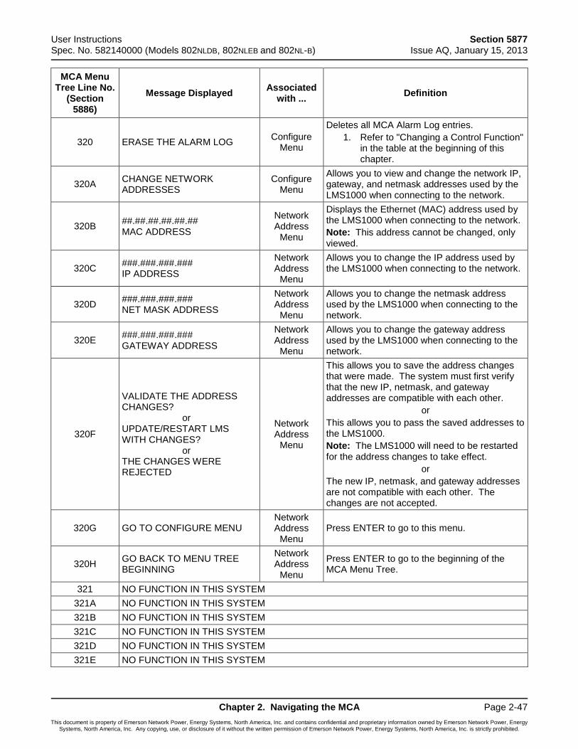
User Instructions Section 5877 Spec. No. 582140000 (Models 802NLDB, 802NLEB and 802NL-B) Issue AQ, January 15, 2013
Chapter 2. Navigating the MCA Page 2-47
This document is property of Emerson Network Power, Energy Systems, North America, Inc. and contains confidential and proprietary information owned by Emerson Network Power, Energy Systems, North America, Inc. Any copying, use, or disclosure of it without the written permission of Emerson Network Power, Energy Systems, North America, Inc. is strictly prohibited.
MCA Menu Tree Line No.
(Section 5886)
Message Displayed Associated
with ... Definition
320 ERASE THE ALARM LOG Configure
Menu
Deletes all MCA Alarm Log entries.
1. Refer to "Changing a Control Function" in the table at the beginning of this chapter.
320A CHANGE NETWORK ADDRESSES
Configure Menu
Allows you to view and change the network IP, gateway, and netmask addresses used by the LMS1000 when connecting to the network.
320B ##.##.##.##.##.## MAC ADDRESS
Network Address
Menu
Displays the Ethernet (MAC) address used by the LMS1000 when connecting to the network.
Note: This address cannot be changed, only viewed.
320C ###.###.###.### IP ADDRESS
Network Address
Menu
Allows you to change the IP address used by the LMS1000 when connecting to the network.
320D ###.###.###.### NET MASK ADDRESS
Network Address
Menu
Allows you to change the netmask address used by the LMS1000 when connecting to the network.
320E ###.###.###.### GATEWAY ADDRESS
Network Address
Menu
Allows you to change the gateway address used by the LMS1000 when connecting to the network.
320F
VALIDATE THE ADDRESS CHANGES? or UPDATE/RESTART LMS WITH CHANGES? or THE CHANGES WERE REJECTED
Network Address
Menu
This allows you to save the address changes that were made. The system must first verify that the new IP, netmask, and gateway addresses are compatible with each other.
or
This allows you to pass the saved addresses to the LMS1000.
Note: The LMS1000 will need to be restarted for the address changes to take effect.
or
The new IP, netmask, and gateway addresses are not compatible with each other. The changes are not accepted.
320G GO TO CONFIGURE MENU Network Address
Menu Press ENTER to go to this menu.
320H GO BACK TO MENU TREE BEGINNING
Network Address
Menu
Press ENTER to go to the beginning of the MCA Menu Tree.
321 NO FUNCTION IN THIS SYSTEM
321A NO FUNCTION IN THIS SYSTEM
321B NO FUNCTION IN THIS SYSTEM
321C NO FUNCTION IN THIS SYSTEM
321D NO FUNCTION IN THIS SYSTEM
321E NO FUNCTION IN THIS SYSTEM
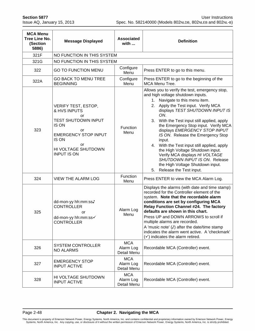
Section 5877 User Instructions Issue AQ, January 15, 2013 Spec. No. 582140000 (Models 802NLDB, 802NLEB and 802NL-B)
Page 2-48 Chapter 2. Navigating the MCA
This document is property of Emerson Network Power, Energy Systems, North America, Inc. and contains confidential and proprietary information owned by Emerson Network Power, Energy Systems, North America, Inc. Any copying, use, or disclosure of it without the written permission of Emerson Network Power, Energy Systems, North America, Inc. is strictly prohibited.
MCA Menu Tree Line No.
(Section 5886)
Message Displayed Associated
with ... Definition
321F NO FUNCTION IN THIS SYSTEM
321G NO FUNCTION IN THIS SYSTEM
322 GO TO FUNCTION MENU Configure
Menu Press ENTER to go to this menu.
322A GO BACK TO MENU TREE BEGINNING
Configure Menu
Press ENTER to go to the beginning of the MCA Menu Tree.
323
VERIFY TEST, ESTOP, & HVS INPUTS or TEST SHUTDOWN INPUT IS ON or EMERGENCY STOP INPUT IS ON or HI VOLTAGE SHUTDOWN INPUT IS ON
Function Menu
Allows you to verify the test, emergency stop, and high voltage shutdown inputs.
1. Navigate to this menu item.
2. Apply the Test input. Verify MCA displays TEST SHUTDOWN INPUT IS ON.
3. With the Test input still applied, apply the Emergency Stop input. Verify MCA displays EMERGENCY STOP INPUT IS ON. Release the Emergency Stop input.
4. With the Test input still applied, apply the High Voltage Shutdown input. Verify MCA displays HI VOLTAGE SHUTDOWN INPUT IS ON. Release the High Voltage Shutdown input.
5. Release the Test input.
324 VIEW THE ALARM LOG Function
Menu Press ENTER to view the MCA Alarm Log.
325
dd-mon-yy hh:mm:ss♪
CONTROLLER
or
dd-mon-yy hh:mm:ss CONTROLLER
Alarm Log Menu
Displays the alarms (with date and time stamp) recorded for the Controller element of the system. Note that the recordable alarm conditions are set by configuring MCA Relay Function Channel #24. The factory defaults are shown in this chart.
Press UP and DOWN ARROWS to scroll if multiple alarms are recorded.
A 'music note' (♪) after the date/time stamp indicates the alarm went active. A 'checkmark' () indicates the alarm retired.
326 SYSTEM CONTROLLER NO ALARMS
MCA Alarm Log
Detail Menu Recordable MCA (Controller) event.
327 EMERGENCY STOP INPUT ACTIVE
MCA Alarm Log
Detail Menu Recordable MCA (Controller) event.
328 HI VOLTAGE SHUTDOWN INPUT ACTIVE
MCA Alarm Log
Detail Menu Recordable MCA (Controller) event.
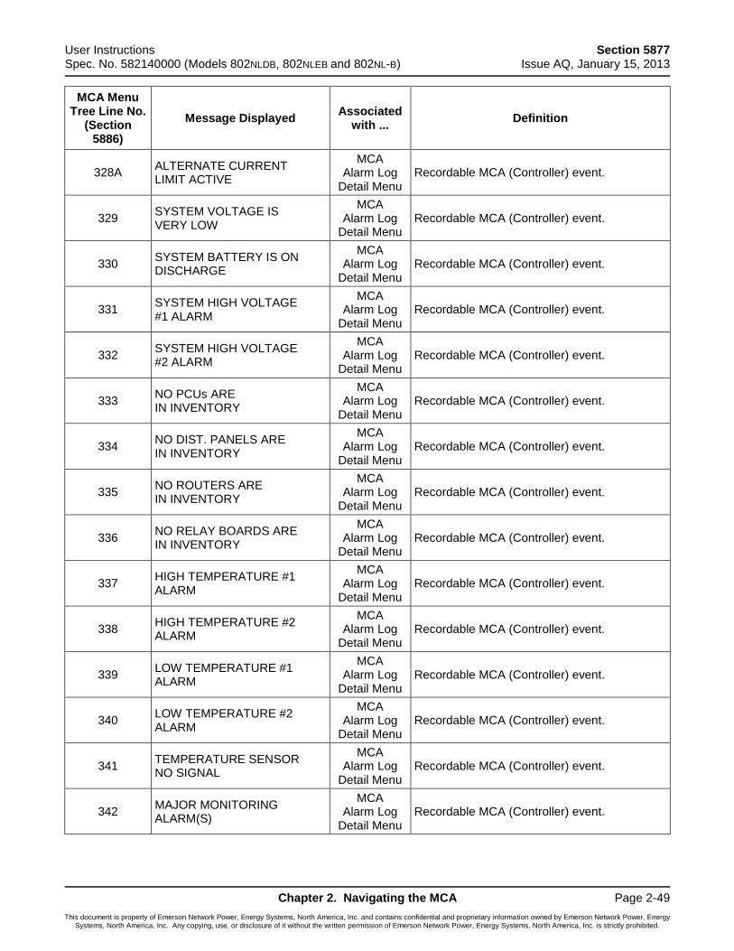
User Instructions Section 5877 Spec. No. 582140000 (Models 802NLDB, 802NLEB and 802NL-B) Issue AQ, January 15, 2013
Chapter 2. Navigating the MCA Page 2-49
This document is property of Emerson Network Power, Energy Systems, North America, Inc. and contains confidential and proprietary information owned by Emerson Network Power, Energy Systems, North America, Inc. Any copying, use, or disclosure of it without the written permission of Emerson Network Power, Energy Systems, North America, Inc. is strictly prohibited.
MCA Menu Tree Line No.
(Section 5886)
Message Displayed Associated
with ... Definition
328A ALTERNATE CURRENT LIMIT ACTIVE
MCA Alarm Log
Detail Menu Recordable MCA (Controller) event.
329 SYSTEM VOLTAGE IS VERY LOW
MCA Alarm Log
Detail Menu Recordable MCA (Controller) event.
330 SYSTEM BATTERY IS ON DISCHARGE
MCA Alarm Log
Detail Menu Recordable MCA (Controller) event.
331 SYSTEM HIGH VOLTAGE #1 ALARM
MCA Alarm Log
Detail Menu Recordable MCA (Controller) event.
332 SYSTEM HIGH VOLTAGE #2 ALARM
MCA Alarm Log
Detail Menu Recordable MCA (Controller) event.
333 NO PCUs ARE IN INVENTORY
MCA Alarm Log
Detail Menu Recordable MCA (Controller) event.
334 NO DIST. PANELS ARE IN INVENTORY
MCA Alarm Log
Detail Menu Recordable MCA (Controller) event.
335 NO ROUTERS ARE IN INVENTORY
MCA Alarm Log
Detail Menu Recordable MCA (Controller) event.
336 NO RELAY BOARDS ARE IN INVENTORY
MCA Alarm Log
Detail Menu Recordable MCA (Controller) event.
337 HIGH TEMPERATURE #1 ALARM
MCA Alarm Log
Detail Menu Recordable MCA (Controller) event.
338 HIGH TEMPERATURE #2 ALARM
MCA Alarm Log
Detail Menu Recordable MCA (Controller) event.
339 LOW TEMPERATURE #1 ALARM
MCA Alarm Log
Detail Menu Recordable MCA (Controller) event.
340 LOW TEMPERATURE #2 ALARM
MCA Alarm Log
Detail Menu Recordable MCA (Controller) event.
341 TEMPERATURE SENSOR NO SIGNAL
MCA Alarm Log
Detail Menu Recordable MCA (Controller) event.
342 MAJOR MONITORING ALARM(S)
MCA Alarm Log
Detail Menu Recordable MCA (Controller) event.
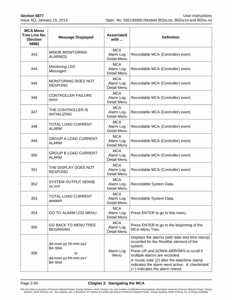
Section 5877 User Instructions Issue AQ, January 15, 2013 Spec. No. 582140000 (Models 802NLDB, 802NLEB and 802NL-B)
Page 2-50 Chapter 2. Navigating the MCA
This document is property of Emerson Network Power, Energy Systems, North America, Inc. and contains confidential and proprietary information owned by Emerson Network Power, Energy Systems, North America, Inc. Any copying, use, or disclosure of it without the written permission of Emerson Network Power, Energy Systems, North America, Inc. is strictly prohibited.
MCA Menu Tree Line No.
(Section 5886)
Message Displayed Associated
with ... Definition
343 MINOR MONITORING ALARM(S)
MCA Alarm Log
Detail Menu Recordable MCA (Controller) event.
344 Monitoring LED Messages
MCA Alarm Log
Detail Menu Recordable MCA (Controller) event.
345 MONITORING DOES NOT RESPOND
MCA Alarm Log
Detail Menu Recordable MCA (Controller) event.
346 CONTROLLER FAILURE ####
MCA Alarm Log
Detail Menu Recordable MCA (Controller) event.
347 THE CONTROLLER IS INITIALIZING
MCA Alarm Log
Detail Menu Recordable MCA (Controller) event.
348 TOTAL LOAD CURRENT ALARM
MCA Alarm Log
Detail Menu Recordable MCA (Controller) event.
349 GROUP A LOAD CURRENT ALARM
MCA Alarm Log
Detail Menu Recordable MCA (Controller) event.
350 GROUP B LOAD CURRENT ALARM
MCA Alarm Log
Detail Menu Recordable MCA (Controller) event.
351 THE DISPLAY DOES NOT RESPOND
MCA Alarm Log
Detail Menu Recordable MCA (Controller) event.
352 SYSTEM OUTPUT SENSE vv.vvV
MCA Alarm Log
Detail Menu Recordable System Data.
353 TOTAL LOAD CURRENT aaaaaA
MCA Alarm Log
Detail Menu Recordable System Data.
354 GO TO ALARM LOG MENU MCA
Alarm Log Detail Menu
Press ENTER to go to this menu.
355 GO BACK TO MENU TREE BEGINNING
MCA Alarm Log
Detail Menu
Press ENTER to go to the beginning of the MCA Menu Tree.
356
dd-mon-yy hh:mm:ss♪ B#-SN#
or
dd-mon-yy hh:mm:ss B#-SN#
Alarm Log Menu
Displays the alarms (with date and time stamp) recorded for the Rectifier element of the system.
Press UP and DOWN ARROWS to scroll if multiple alarms are recorded.
A 'music note' (♪) after the date/time stamp indicates the alarm went active. A 'checkmark' () indicates the alarm retired.
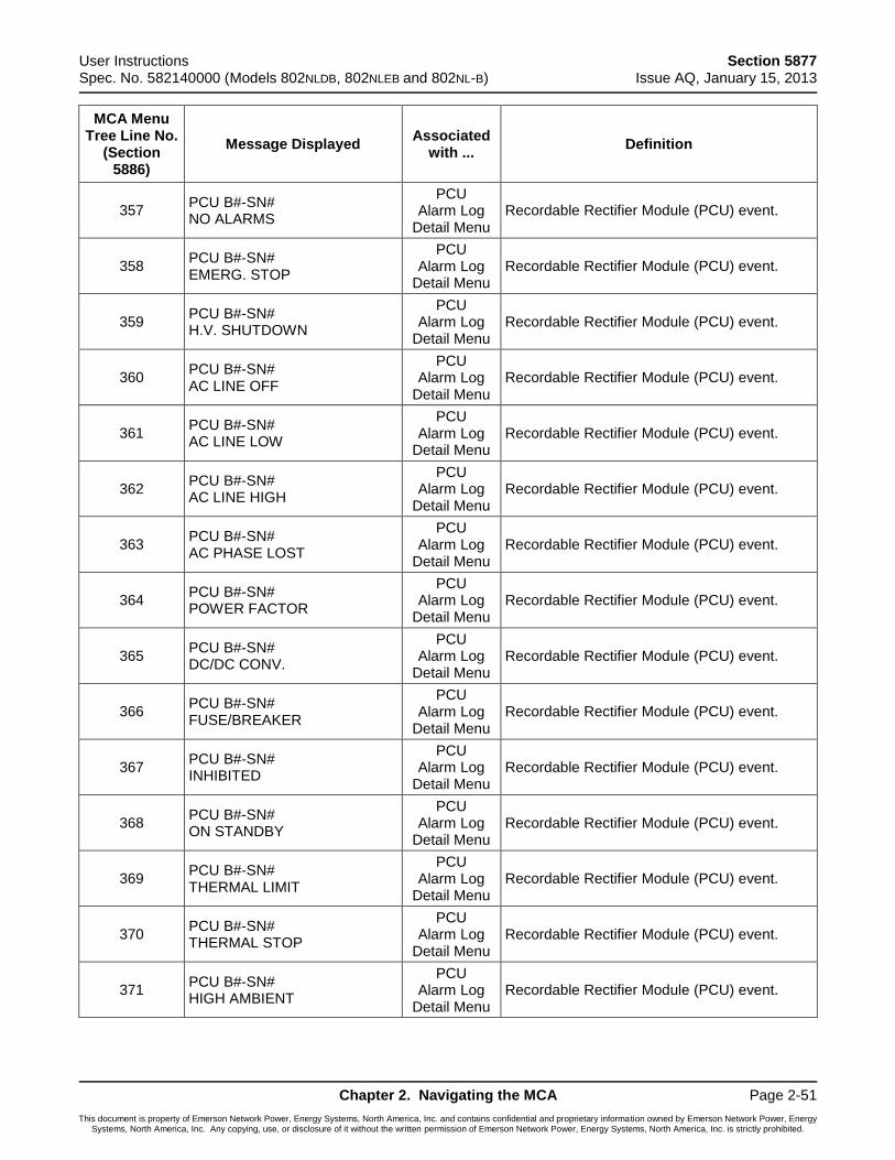
User Instructions Section 5877 Spec. No. 582140000 (Models 802NLDB, 802NLEB and 802NL-B) Issue AQ, January 15, 2013
Chapter 2. Navigating the MCA Page 2-51
This document is property of Emerson Network Power, Energy Systems, North America, Inc. and contains confidential and proprietary information owned by Emerson Network Power, Energy Systems, North America, Inc. Any copying, use, or disclosure of it without the written permission of Emerson Network Power, Energy Systems, North America, Inc. is strictly prohibited.
MCA Menu Tree Line No.
(Section 5886)
Message Displayed Associated
with ... Definition
357 PCU B#-SN# NO ALARMS
PCU Alarm Log
Detail Menu Recordable Rectifier Module (PCU) event.
358 PCU B#-SN# EMERG. STOP
PCU Alarm Log
Detail Menu Recordable Rectifier Module (PCU) event.
359 PCU B#-SN# H.V. SHUTDOWN
PCU Alarm Log
Detail Menu Recordable Rectifier Module (PCU) event.
360 PCU B#-SN# AC LINE OFF
PCU Alarm Log
Detail Menu Recordable Rectifier Module (PCU) event.
361 PCU B#-SN# AC LINE LOW
PCU Alarm Log
Detail Menu Recordable Rectifier Module (PCU) event.
362 PCU B#-SN# AC LINE HIGH
PCU Alarm Log
Detail Menu Recordable Rectifier Module (PCU) event.
363 PCU B#-SN# AC PHASE LOST
PCU Alarm Log
Detail Menu Recordable Rectifier Module (PCU) event.
364 PCU B#-SN# POWER FACTOR
PCU Alarm Log
Detail Menu Recordable Rectifier Module (PCU) event.
365 PCU B#-SN# DC/DC CONV.
PCU Alarm Log
Detail Menu Recordable Rectifier Module (PCU) event.
366 PCU B#-SN# FUSE/BREAKER
PCU Alarm Log
Detail Menu Recordable Rectifier Module (PCU) event.
367 PCU B#-SN# INHIBITED
PCU Alarm Log
Detail Menu Recordable Rectifier Module (PCU) event.
368 PCU B#-SN# ON STANDBY
PCU Alarm Log
Detail Menu Recordable Rectifier Module (PCU) event.
369 PCU B#-SN# THERMAL LIMIT
PCU Alarm Log
Detail Menu Recordable Rectifier Module (PCU) event.
370 PCU B#-SN# THERMAL STOP
PCU Alarm Log
Detail Menu Recordable Rectifier Module (PCU) event.
371 PCU B#-SN# HIGH AMBIENT
PCU Alarm Log
Detail Menu Recordable Rectifier Module (PCU) event.
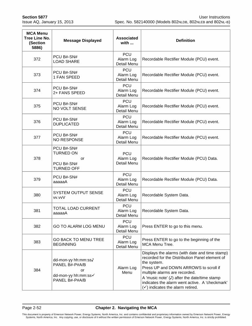
Section 5877 User Instructions Issue AQ, January 15, 2013 Spec. No. 582140000 (Models 802NLDB, 802NLEB and 802NL-B)
Page 2-52 Chapter 2. Navigating the MCA
This document is property of Emerson Network Power, Energy Systems, North America, Inc. and contains confidential and proprietary information owned by Emerson Network Power, Energy Systems, North America, Inc. Any copying, use, or disclosure of it without the written permission of Emerson Network Power, Energy Systems, North America, Inc. is strictly prohibited.
MCA Menu Tree Line No.
(Section 5886)
Message Displayed Associated
with ... Definition
372 PCU B#-SN# LOAD SHARE
PCU Alarm Log
Detail Menu Recordable Rectifier Module (PCU) event.
373 PCU B#-SN# 1 FAN SPEED
PCU Alarm Log
Detail Menu Recordable Rectifier Module (PCU) event.
374 PCU B#-SN# 2+ FANS SPEED
PCU Alarm Log
Detail Menu Recordable Rectifier Module (PCU) event.
375 PCU B#-SN# NO VOLT SENSE
PCU Alarm Log
Detail Menu Recordable Rectifier Module (PCU) event.
376 PCU B#-SN# DUPLICATED
PCU Alarm Log
Detail Menu Recordable Rectifier Module (PCU) event.
377 PCU B#-SN# NO RESPONSE
PCU Alarm Log
Detail Menu Recordable Rectifier Module (PCU) event.
378
PCU B#-SN# TURNED ON
or
PCU B#-SN# TURNED OFF
PCU Alarm Log
Detail Menu Recordable Rectifier Module (PCU) Data.
379 PCU B#-SN# aaaaaA
PCU Alarm Log
Detail Menu Recordable Rectifier Module (PCU) Data.
380 SYSTEM OUTPUT SENSE vv.vvV
PCU Alarm Log
Detail Menu Recordable System Data.
381 TOTAL LOAD CURRENT aaaaaA
PCU Alarm Log
Detail Menu Recordable System Data.
382 GO TO ALARM LOG MENU PCU
Alarm Log Detail Menu
Press ENTER to go to this menu.
383 GO BACK TO MENU TREE BEGINNING
PCU Alarm Log
Detail Menu
Press ENTER to go to the beginning of the MCA Menu Tree.
384
dd-mon-yy hh:mm:ss♪ PANEL B#-P#A/B
or
dd-mon-yy hh:mm:ss PANEL B#-P#A/B
Alarm Log Menu
Displays the alarms (with date and time stamp) recorded for the Distribution Panel element of the system.
Press UP and DOWN ARROWS to scroll if multiple alarms are recorded.
A 'music note' (♪) after the date/time stamp indicates the alarm went active. A 'checkmark' () indicates the alarm retired.
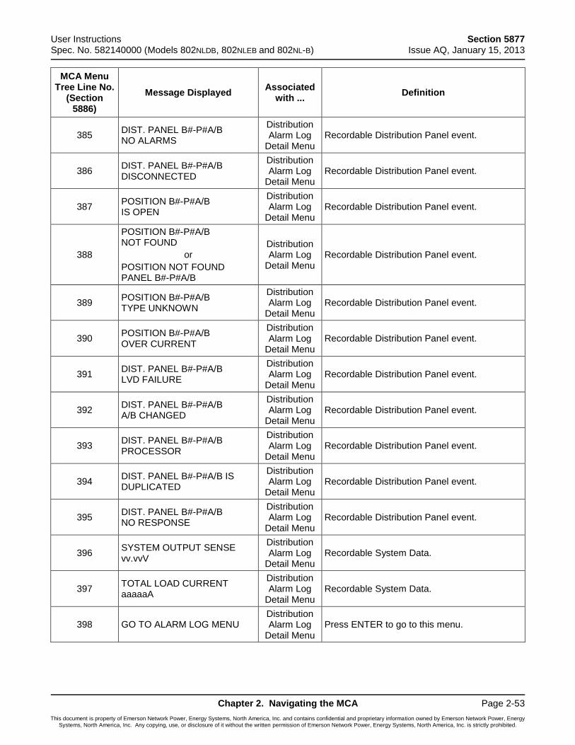
User Instructions Section 5877 Spec. No. 582140000 (Models 802NLDB, 802NLEB and 802NL-B) Issue AQ, January 15, 2013
Chapter 2. Navigating the MCA Page 2-53
This document is property of Emerson Network Power, Energy Systems, North America, Inc. and contains confidential and proprietary information owned by Emerson Network Power, Energy Systems, North America, Inc. Any copying, use, or disclosure of it without the written permission of Emerson Network Power, Energy Systems, North America, Inc. is strictly prohibited.
MCA Menu Tree Line No.
(Section 5886)
Message Displayed Associated
with ... Definition
385 DIST. PANEL B#-P#A/B NO ALARMS
Distribution Alarm Log
Detail Menu Recordable Distribution Panel event.
386 DIST. PANEL B#-P#A/B DISCONNECTED
Distribution Alarm Log
Detail Menu Recordable Distribution Panel event.
387 POSITION B#-P#A/B IS OPEN
Distribution Alarm Log
Detail Menu Recordable Distribution Panel event.
388
POSITION B#-P#A/B NOT FOUND
or
POSITION NOT FOUND PANEL B#-P#A/B
Distribution Alarm Log
Detail Menu Recordable Distribution Panel event.
389 POSITION B#-P#A/B TYPE UNKNOWN
Distribution Alarm Log
Detail Menu Recordable Distribution Panel event.
390 POSITION B#-P#A/B OVER CURRENT
Distribution Alarm Log
Detail Menu Recordable Distribution Panel event.
391 DIST. PANEL B#-P#A/B LVD FAILURE
Distribution Alarm Log
Detail Menu Recordable Distribution Panel event.
392 DIST. PANEL B#-P#A/B A/B CHANGED
Distribution Alarm Log
Detail Menu Recordable Distribution Panel event.
393 DIST. PANEL B#-P#A/B PROCESSOR
Distribution Alarm Log
Detail Menu Recordable Distribution Panel event.
394 DIST. PANEL B#-P#A/B IS DUPLICATED
Distribution Alarm Log
Detail Menu Recordable Distribution Panel event.
395 DIST. PANEL B#-P#A/B NO RESPONSE
Distribution Alarm Log
Detail Menu Recordable Distribution Panel event.
396 SYSTEM OUTPUT SENSE vv.vvV
Distribution Alarm Log
Detail Menu Recordable System Data.
397 TOTAL LOAD CURRENT aaaaaA
Distribution Alarm Log
Detail Menu Recordable System Data.
398 GO TO ALARM LOG MENU Distribution Alarm Log
Detail Menu Press ENTER to go to this menu.
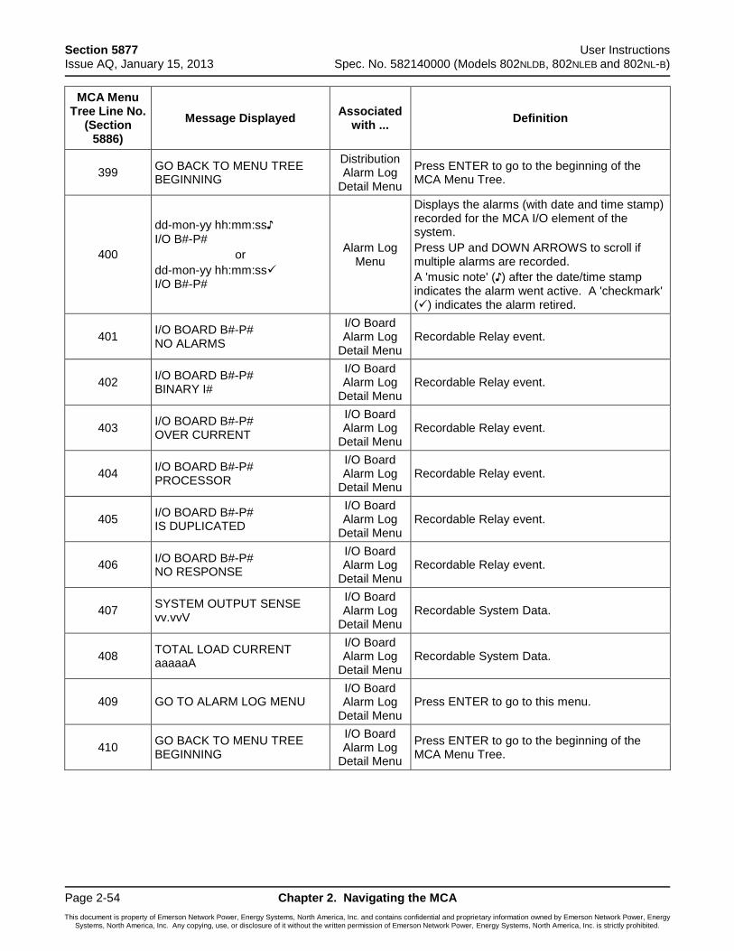
Section 5877 User Instructions Issue AQ, January 15, 2013 Spec. No. 582140000 (Models 802NLDB, 802NLEB and 802NL-B)
Page 2-54 Chapter 2. Navigating the MCA
This document is property of Emerson Network Power, Energy Systems, North America, Inc. and contains confidential and proprietary information owned by Emerson Network Power, Energy Systems, North America, Inc. Any copying, use, or disclosure of it without the written permission of Emerson Network Power, Energy Systems, North America, Inc. is strictly prohibited.
MCA Menu Tree Line No.
(Section 5886)
Message Displayed Associated
with ... Definition
399 GO BACK TO MENU TREE BEGINNING
Distribution Alarm Log
Detail Menu
Press ENTER to go to the beginning of the MCA Menu Tree.
400
dd-mon-yy hh:mm:ss♪
I/O B#-P#
or
dd-mon-yy hh:mm:ss I/O B#-P#
Alarm Log Menu
Displays the alarms (with date and time stamp) recorded for the MCA I/O element of the system.
Press UP and DOWN ARROWS to scroll if multiple alarms are recorded.
A 'music note' (♪) after the date/time stamp indicates the alarm went active. A 'checkmark' () indicates the alarm retired.
401 I/O BOARD B#-P# NO ALARMS
I/O Board Alarm Log
Detail Menu Recordable Relay event.
402 I/O BOARD B#-P# BINARY I#
I/O Board Alarm Log
Detail Menu Recordable Relay event.
403 I/O BOARD B#-P# OVER CURRENT
I/O Board Alarm Log
Detail Menu Recordable Relay event.
404 I/O BOARD B#-P# PROCESSOR
I/O Board Alarm Log
Detail Menu Recordable Relay event.
405 I/O BOARD B#-P# IS DUPLICATED
I/O Board Alarm Log
Detail Menu Recordable Relay event.
406 I/O BOARD B#-P# NO RESPONSE
I/O Board Alarm Log
Detail Menu Recordable Relay event.
407 SYSTEM OUTPUT SENSE vv.vvV
I/O Board Alarm Log
Detail Menu Recordable System Data.
408 TOTAL LOAD CURRENT aaaaaA
I/O Board Alarm Log
Detail Menu Recordable System Data.
409 GO TO ALARM LOG MENU I/O Board Alarm Log
Detail Menu Press ENTER to go to this menu.
410 GO BACK TO MENU TREE BEGINNING
I/O Board Alarm Log
Detail Menu
Press ENTER to go to the beginning of the MCA Menu Tree.
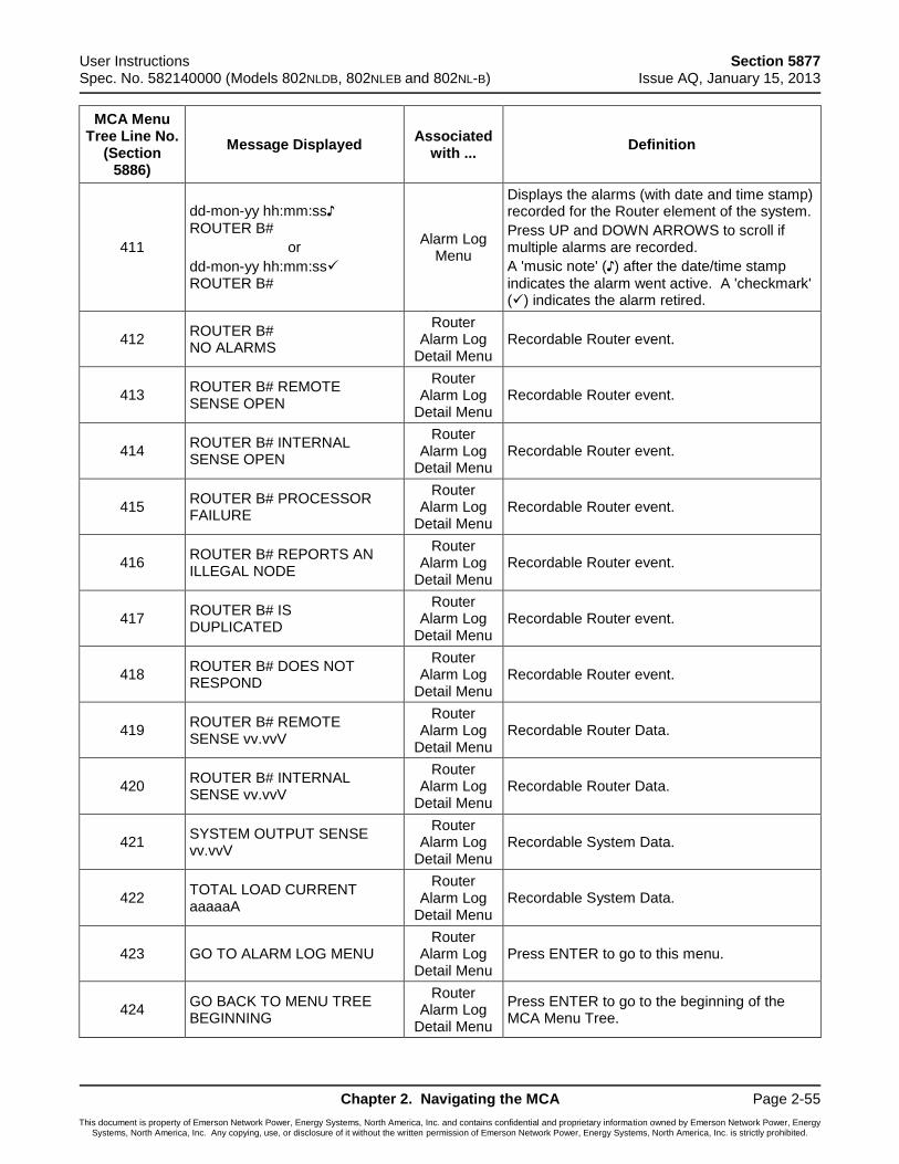
User Instructions Section 5877 Spec. No. 582140000 (Models 802NLDB, 802NLEB and 802NL-B) Issue AQ, January 15, 2013
Chapter 2. Navigating the MCA Page 2-55
This document is property of Emerson Network Power, Energy Systems, North America, Inc. and contains confidential and proprietary information owned by Emerson Network Power, Energy Systems, North America, Inc. Any copying, use, or disclosure of it without the written permission of Emerson Network Power, Energy Systems, North America, Inc. is strictly prohibited.
MCA Menu Tree Line No.
(Section 5886)
Message Displayed Associated
with ... Definition
411
dd-mon-yy hh:mm:ss♪
ROUTER B#
or
dd-mon-yy hh:mm:ss ROUTER B#
Alarm Log Menu
Displays the alarms (with date and time stamp) recorded for the Router element of the system.
Press UP and DOWN ARROWS to scroll if multiple alarms are recorded.
A 'music note' (♪) after the date/time stamp
indicates the alarm went active. A 'checkmark' () indicates the alarm retired.
412 ROUTER B# NO ALARMS
Router Alarm Log
Detail Menu Recordable Router event.
413 ROUTER B# REMOTE SENSE OPEN
Router Alarm Log
Detail Menu Recordable Router event.
414 ROUTER B# INTERNAL SENSE OPEN
Router Alarm Log
Detail Menu Recordable Router event.
415 ROUTER B# PROCESSOR FAILURE
Router Alarm Log
Detail Menu Recordable Router event.
416 ROUTER B# REPORTS AN ILLEGAL NODE
Router Alarm Log
Detail Menu Recordable Router event.
417 ROUTER B# IS DUPLICATED
Router Alarm Log
Detail Menu Recordable Router event.
418 ROUTER B# DOES NOT RESPOND
Router Alarm Log
Detail Menu Recordable Router event.
419 ROUTER B# REMOTE SENSE vv.vvV
Router Alarm Log
Detail Menu Recordable Router Data.
420 ROUTER B# INTERNAL SENSE vv.vvV
Router Alarm Log
Detail Menu Recordable Router Data.
421 SYSTEM OUTPUT SENSE vv.vvV
Router Alarm Log
Detail Menu Recordable System Data.
422 TOTAL LOAD CURRENT aaaaaA
Router Alarm Log
Detail Menu Recordable System Data.
423 GO TO ALARM LOG MENU Router
Alarm Log Detail Menu
Press ENTER to go to this menu.
424 GO BACK TO MENU TREE BEGINNING
Router Alarm Log
Detail Menu
Press ENTER to go to the beginning of the MCA Menu Tree.
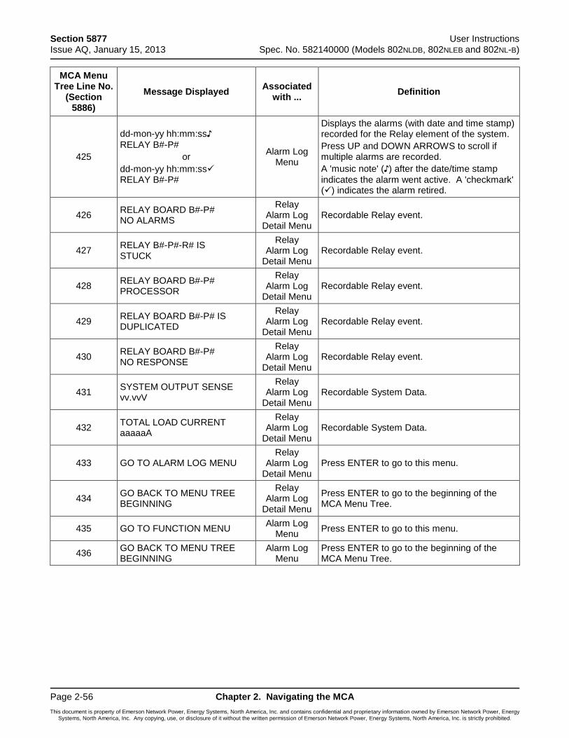
Section 5877 User Instructions Issue AQ, January 15, 2013 Spec. No. 582140000 (Models 802NLDB, 802NLEB and 802NL-B)
Page 2-56 Chapter 2. Navigating the MCA
This document is property of Emerson Network Power, Energy Systems, North America, Inc. and contains confidential and proprietary information owned by Emerson Network Power, Energy Systems, North America, Inc. Any copying, use, or disclosure of it without the written permission of Emerson Network Power, Energy Systems, North America, Inc. is strictly prohibited.
MCA Menu Tree Line No.
(Section 5886)
Message Displayed Associated
with ... Definition
425
dd-mon-yy hh:mm:ss♪
RELAY B#-P#
or
dd-mon-yy hh:mm:ss RELAY B#-P#
Alarm Log Menu
Displays the alarms (with date and time stamp) recorded for the Relay element of the system.
Press UP and DOWN ARROWS to scroll if multiple alarms are recorded.
A 'music note' (♪) after the date/time stamp
indicates the alarm went active. A 'checkmark' () indicates the alarm retired.
426 RELAY BOARD B#-P# NO ALARMS
Relay Alarm Log
Detail Menu Recordable Relay event.
427 RELAY B#-P#-R# IS STUCK
Relay Alarm Log
Detail Menu Recordable Relay event.
428 RELAY BOARD B#-P# PROCESSOR
Relay Alarm Log
Detail Menu Recordable Relay event.
429 RELAY BOARD B#-P# IS DUPLICATED
Relay Alarm Log
Detail Menu Recordable Relay event.
430 RELAY BOARD B#-P# NO RESPONSE
Relay Alarm Log
Detail Menu Recordable Relay event.
431 SYSTEM OUTPUT SENSE vv.vvV
Relay Alarm Log
Detail Menu Recordable System Data.
432 TOTAL LOAD CURRENT aaaaaA
Relay Alarm Log
Detail Menu Recordable System Data.
433 GO TO ALARM LOG MENU Relay
Alarm Log Detail Menu
Press ENTER to go to this menu.
434 GO BACK TO MENU TREE BEGINNING
Relay Alarm Log
Detail Menu
Press ENTER to go to the beginning of the MCA Menu Tree.
435 GO TO FUNCTION MENU Alarm Log
Menu Press ENTER to go to this menu.
436 GO BACK TO MENU TREE BEGINNING
Alarm Log Menu
Press ENTER to go to the beginning of the MCA Menu Tree.
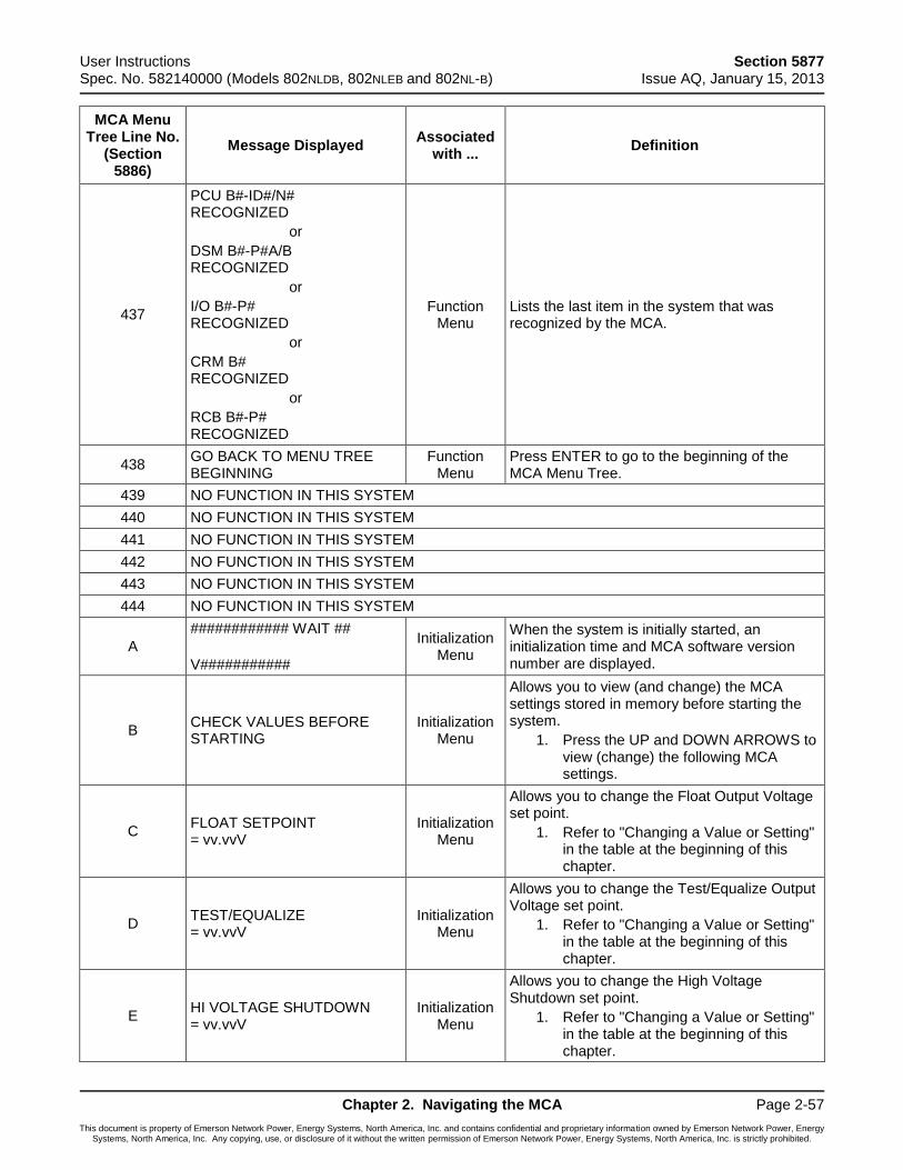
User Instructions Section 5877 Spec. No. 582140000 (Models 802NLDB, 802NLEB and 802NL-B) Issue AQ, January 15, 2013
Chapter 2. Navigating the MCA Page 2-57
This document is property of Emerson Network Power, Energy Systems, North America, Inc. and contains confidential and proprietary information owned by Emerson Network Power, Energy Systems, North America, Inc. Any copying, use, or disclosure of it without the written permission of Emerson Network Power, Energy Systems, North America, Inc. is strictly prohibited.
MCA Menu Tree Line No.
(Section 5886)
Message Displayed Associated
with ... Definition
437
PCU B#-ID#/N# RECOGNIZED
or
DSM B#-P#A/B RECOGNIZED
or
I/O B#-P# RECOGNIZED
or
CRM B# RECOGNIZED
or
RCB B#-P# RECOGNIZED
Function Menu
Lists the last item in the system that was recognized by the MCA.
438 GO BACK TO MENU TREE BEGINNING
Function Menu
Press ENTER to go to the beginning of the MCA Menu Tree.
439 NO FUNCTION IN THIS SYSTEM
440 NO FUNCTION IN THIS SYSTEM
441 NO FUNCTION IN THIS SYSTEM
442 NO FUNCTION IN THIS SYSTEM
443 NO FUNCTION IN THIS SYSTEM
444 NO FUNCTION IN THIS SYSTEM
A
############ WAIT ##
V###########
Initialization Menu
When the system is initially started, an initialization time and MCA software version number are displayed.
B CHECK VALUES BEFORE STARTING
Initialization Menu
Allows you to view (and change) the MCA settings stored in memory before starting the system.
1. Press the UP and DOWN ARROWS to view (change) the following MCA settings.
C FLOAT SETPOINT = vv.vvV
Initialization Menu
Allows you to change the Float Output Voltage set point.
1. Refer to "Changing a Value or Setting" in the table at the beginning of this chapter.
D TEST/EQUALIZE = vv.vvV
Initialization Menu
Allows you to change the Test/Equalize Output Voltage set point.
1. Refer to "Changing a Value or Setting" in the table at the beginning of this chapter.
E HI VOLTAGE SHUTDOWN = vv.vvV
Initialization Menu
Allows you to change the High Voltage Shutdown set point.
1. Refer to "Changing a Value or Setting" in the table at the beginning of this chapter.
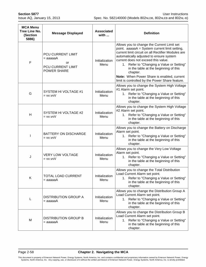
Section 5877 User Instructions Issue AQ, January 15, 2013 Spec. No. 582140000 (Models 802NLDB, 802NLEB and 802NL-B)
Page 2-58 Chapter 2. Navigating the MCA
This document is property of Emerson Network Power, Energy Systems, North America, Inc. and contains confidential and proprietary information owned by Emerson Network Power, Energy Systems, North America, Inc. Any copying, use, or disclosure of it without the written permission of Emerson Network Power, Energy Systems, North America, Inc. is strictly prohibited.
MCA Menu Tree Line No.
(Section 5886)
Message Displayed Associated
with ... Definition
F
PCU CURRENT LIMIT = aaaaaA
or
PCU CURRENT LIMIT POWER SHARE
Initialization Menu
Allows you to change the Current Limit set point. aaaaaA = System current limit setting, current limit circuit on all Rectifier Modules are automatically adjusted to ensure system current does not exceed this value.
1. Refer to "Changing a Value or Setting" in the table at the beginning of this chapter.
Note: When Power Share is enabled, current limit is controlled by the Power Share feature.
G SYSTEM HI VOLTAGE #1 = vv.vvV
Initialization Menu
Allows you to change the System High Voltage #1 Alarm set point.
1. Refer to "Changing a Value or Setting" in the table at the beginning of this chapter.
H SYSTEM HI VOLTAGE #2 = vv.vvV
Initialization Menu
Allows you to change the System High Voltage #2 Alarm set point.
1. Refer to "Changing a Value or Setting" in the table at the beginning of this chapter.
I BATTERY ON DISCHARGE = vv.vvV
Initialization Menu
Allows you to change the Battery on Discharge Alarm set point.
1. Refer to "Changing a Value or Setting" in the table at the beginning of this chapter.
J VERY LOW VOLTAGE = vv.vvV
Initialization Menu
Allows you to change the Very Low Voltage Alarm set point.
1. Refer to "Changing a Value or Setting" in the table at the beginning of this chapter.
K TOTAL LOAD CURRENT = aaaaaA
Initialization Menu
Allows you to change the Total Distribution Load Current Alarm set point.
1. Refer to "Changing a Value or Setting" in the table at the beginning of this chapter.
L DISTRIBUTION GROUP A = aaaaaA
Initialization Menu
Allows you to change the Distribution Group A Load Current Alarm set point.
1. Refer to "Changing a Value or Setting" in the table at the beginning of this chapter.
M DISTRIBUTION GROUP B = aaaaaA
Initialization Menu
Allows you to change the Distribution Group B Load Current Alarm set point.
1. Refer to "Changing a Value or Setting" in the table at the beginning of this chapter.
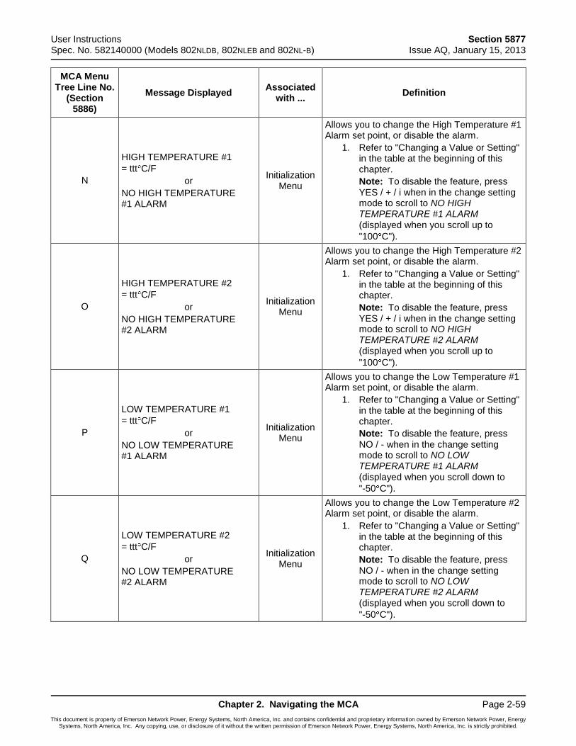
User Instructions Section 5877 Spec. No. 582140000 (Models 802NLDB, 802NLEB and 802NL-B) Issue AQ, January 15, 2013
Chapter 2. Navigating the MCA Page 2-59
This document is property of Emerson Network Power, Energy Systems, North America, Inc. and contains confidential and proprietary information owned by Emerson Network Power, Energy Systems, North America, Inc. Any copying, use, or disclosure of it without the written permission of Emerson Network Power, Energy Systems, North America, Inc. is strictly prohibited.
MCA Menu Tree Line No.
(Section 5886)
Message Displayed Associated
with ... Definition
N
HIGH TEMPERATURE #1
= ttt C/F
or
NO HIGH TEMPERATURE #1 ALARM
Initialization Menu
Allows you to change the High Temperature #1 Alarm set point, or disable the alarm.
1. Refer to "Changing a Value or Setting" in the table at the beginning of this chapter.
Note: To disable the feature, press YES / + / i when in the change setting mode to scroll to NO HIGH TEMPERATURE #1 ALARM (displayed when you scroll up to
"100 C").
O
HIGH TEMPERATURE #2
= ttt C/F
or
NO HIGH TEMPERATURE #2 ALARM
Initialization Menu
Allows you to change the High Temperature #2 Alarm set point, or disable the alarm.
1. Refer to "Changing a Value or Setting" in the table at the beginning of this chapter.
Note: To disable the feature, press YES / + / i when in the change setting mode to scroll to NO HIGH TEMPERATURE #2 ALARM (displayed when you scroll up to
"100 C").
P
LOW TEMPERATURE #1
= ttt C/F
or
NO LOW TEMPERATURE #1 ALARM
Initialization Menu
Allows you to change the Low Temperature #1 Alarm set point, or disable the alarm.
1. Refer to "Changing a Value or Setting" in the table at the beginning of this chapter.
Note: To disable the feature, press NO / - when in the change setting mode to scroll to NO LOW TEMPERATURE #1 ALARM (displayed when you scroll down to
"-50 C").
Q
LOW TEMPERATURE #2
= ttt C/F
or
NO LOW TEMPERATURE #2 ALARM
Initialization Menu
Allows you to change the Low Temperature #2 Alarm set point, or disable the alarm.
1. Refer to "Changing a Value or Setting" in the table at the beginning of this chapter.
Note: To disable the feature, press NO / - when in the change setting mode to scroll to NO LOW TEMPERATURE #2 ALARM (displayed when you scroll down to
"-50 C").
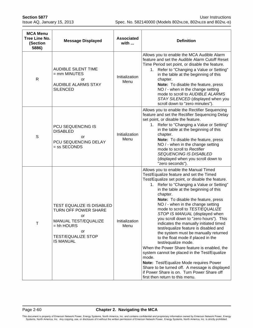
Section 5877 User Instructions Issue AQ, January 15, 2013 Spec. No. 582140000 (Models 802NLDB, 802NLEB and 802NL-B)
Page 2-60 Chapter 2. Navigating the MCA
This document is property of Emerson Network Power, Energy Systems, North America, Inc. and contains confidential and proprietary information owned by Emerson Network Power, Energy Systems, North America, Inc. Any copying, use, or disclosure of it without the written permission of Emerson Network Power, Energy Systems, North America, Inc. is strictly prohibited.
MCA Menu Tree Line No.
(Section 5886)
Message Displayed Associated
with ... Definition
R
AUDIBLE SILENT TIME = mm MINUTES
or
AUDIBLE ALARMS STAY SILENCED
Initialization Menu
Allows you to enable the MCA Audible Alarm feature and set the Audible Alarm Cutoff Reset Time Period set point, or disable the feature.
1. Refer to "Changing a Value or Setting" in the table at the beginning of this chapter.
Note: To disable the feature, press NO / - when in the change setting mode to scroll to AUDIBLE ALARMS STAY SILENCED (displayed when you scroll down to "zero minutes").
S
PCU SEQUENCING IS DISABLED
or
PCU SEQUENCING DELAY = ss SECONDS
Initialization Menu
Allows you to enable the Rectifier Sequencing feature and set the Rectifier Sequencing Delay set point, or disable the feature.
1. Refer to "Changing a Value or Setting" in the table at the beginning of this chapter.
Note: To disable the feature, press NO / - when in the change setting mode to scroll to Rectifier SEQUENCING IS DISABLED (displayed when you scroll down to "zero seconds").
T
TEST EQUALIZE IS DISABLED TURN OFF POWER SHARE
or
MANUAL TEST/EQUALIZE = hh HOURS
or
TEST/EQUALIZE STOP IS MANUAL
Initialization Menu
Allows you to enable the Manual Timed Test/Equalize feature and set the Timed Test/Equalize set point, or disable the feature.
1. Refer to "Changing a Value or Setting" in the table at the beginning of this chapter.
Note: To disable the feature, press NO / - when in the change setting mode to scroll to TEST/EQUALIZE STOP IS MANUAL (displayed when you scroll down to "zero hours"). This indicates the manually initiated timed test/equalize feature is disabled and the system must be manually returned to the float mode if placed in the test/equalize mode.
When the Power Share feature is enabled, the system cannot be placed in the Test/Equalize mode.
Note: Test/Equalize Mode requires Power Share to be turned off. A message is displayed if Power Share is on. Turn Power Share off first then return to this menu.
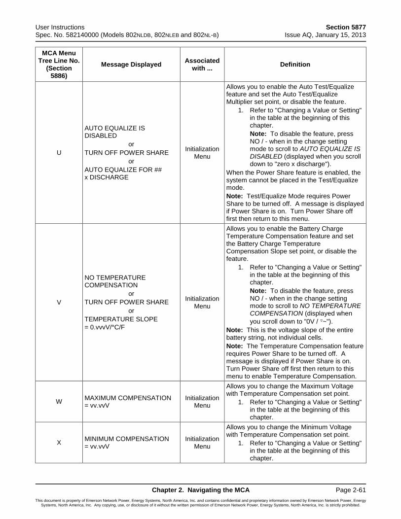
User Instructions Section 5877 Spec. No. 582140000 (Models 802NLDB, 802NLEB and 802NL-B) Issue AQ, January 15, 2013
Chapter 2. Navigating the MCA Page 2-61
This document is property of Emerson Network Power, Energy Systems, North America, Inc. and contains confidential and proprietary information owned by Emerson Network Power, Energy Systems, North America, Inc. Any copying, use, or disclosure of it without the written permission of Emerson Network Power, Energy Systems, North America, Inc. is strictly prohibited.
MCA Menu Tree Line No.
(Section 5886)
Message Displayed Associated
with ... Definition
U
AUTO EQUALIZE IS DISABLED
or
TURN OFF POWER SHARE
or
AUTO EQUALIZE FOR ## x DISCHARGE
Initialization Menu
Allows you to enable the Auto Test/Equalize feature and set the Auto Test/Equalize Multiplier set point, or disable the feature.
1. Refer to "Changing a Value or Setting" in the table at the beginning of this chapter.
Note: To disable the feature, press NO / - when in the change setting mode to scroll to AUTO EQUALIZE IS DISABLED (displayed when you scroll down to "zero x discharge").
When the Power Share feature is enabled, the system cannot be placed in the Test/Equalize mode.
Note: Test/Equalize Mode requires Power Share to be turned off. A message is displayed if Power Share is on. Turn Power Share off first then return to this menu.
V
NO TEMPERATURE COMPENSATION
or
TURN OFF POWER SHARE
or
TEMPERATURE SLOPE
= 0.vvvV/ C/F
Initialization Menu
Allows you to enable the Battery Charge Temperature Compensation feature and set the Battery Charge Temperature Compensation Slope set point, or disable the feature.
1. Refer to "Changing a Value or Setting" in the table at the beginning of this chapter.
Note: To disable the feature, press NO / - when in the change setting mode to scroll to NO TEMPERATURE COMPENSATION (displayed when
you scroll down to "0V / ~").
Note: This is the voltage slope of the entire battery string, not individual cells.
Note: The Temperature Compensation feature requires Power Share to be turned off. A message is displayed if Power Share is on. Turn Power Share off first then return to this menu to enable Temperature Compensation.
W MAXIMUM COMPENSATION = vv.vvV
Initialization Menu
Allows you to change the Maximum Voltage with Temperature Compensation set point.
1. Refer to "Changing a Value or Setting" in the table at the beginning of this chapter.
X MINIMUM COMPENSATION = vv.vvV
Initialization Menu
Allows you to change the Minimum Voltage with Temperature Compensation set point.
1. Refer to "Changing a Value or Setting" in the table at the beginning of this chapter.
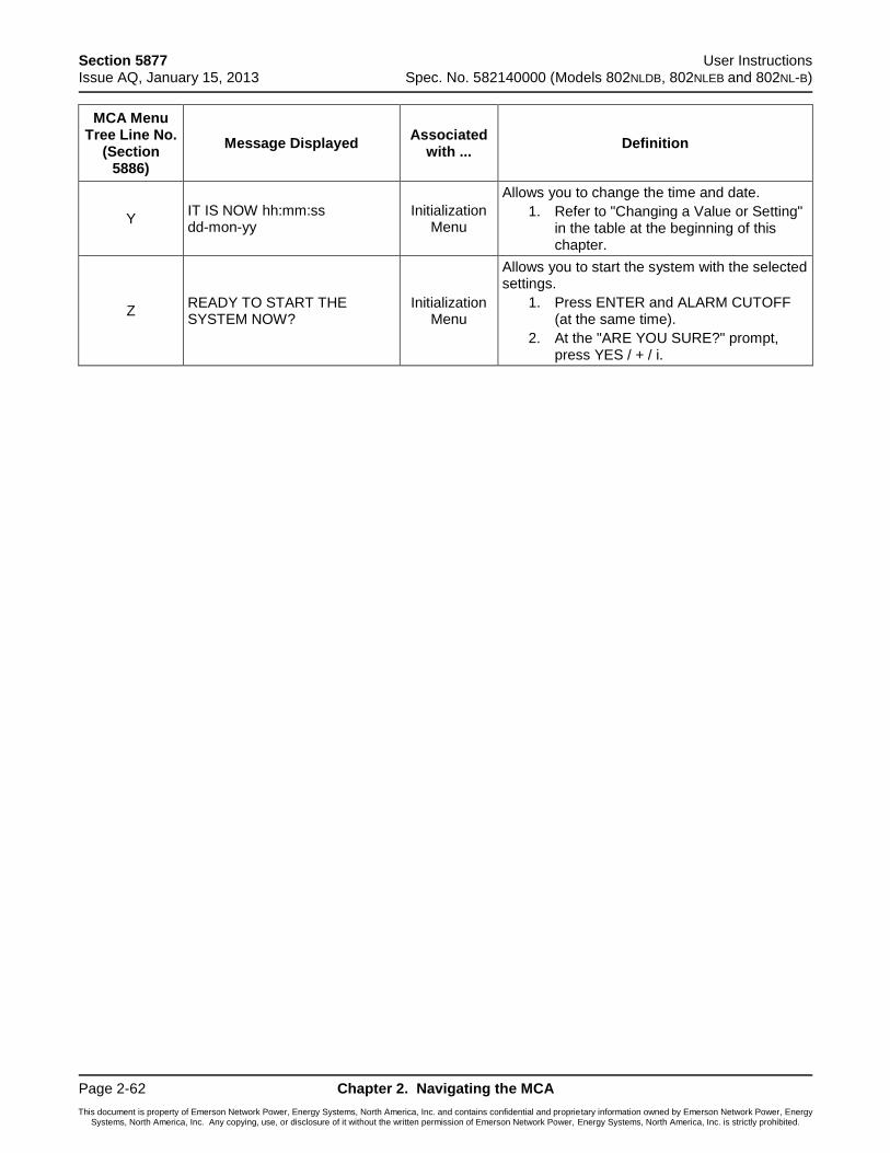
Section 5877 User Instructions Issue AQ, January 15, 2013 Spec. No. 582140000 (Models 802NLDB, 802NLEB and 802NL-B)
Page 2-62 Chapter 2. Navigating the MCA
This document is property of Emerson Network Power, Energy Systems, North America, Inc. and contains confidential and proprietary information owned by Emerson Network Power, Energy Systems, North America, Inc. Any copying, use, or disclosure of it without the written permission of Emerson Network Power, Energy Systems, North America, Inc. is strictly prohibited.
MCA Menu Tree Line No.
(Section 5886)
Message Displayed Associated
with ... Definition
Y IT IS NOW hh:mm:ss dd-mon-yy
Initialization Menu
Allows you to change the time and date.
1. Refer to "Changing a Value or Setting" in the table at the beginning of this chapter.
Z READY TO START THE SYSTEM NOW?
Initialization Menu
Allows you to start the system with the selected settings.
1. Press ENTER and ALARM CUTOFF (at the same time).
2. At the "ARE YOU SURE?" prompt, press YES / + / i.
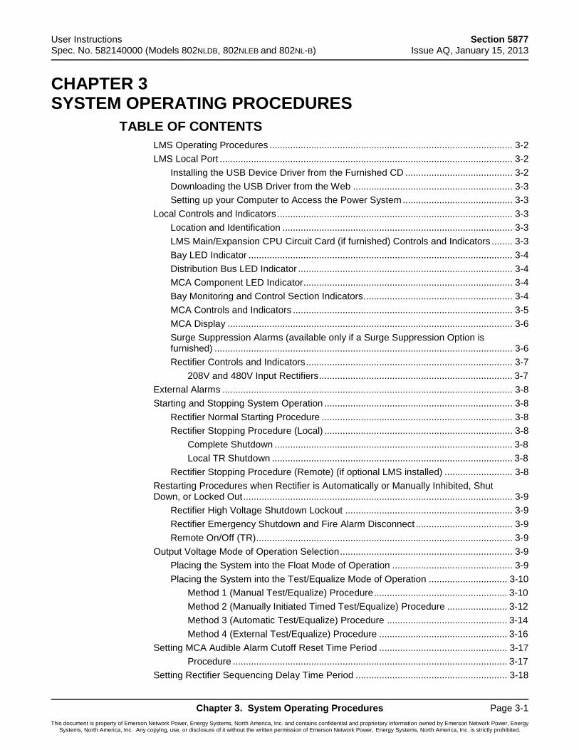
User Instructions Section 5877 Spec. No. 582140000 (Models 802NLDB, 802NLEB and 802NL-B) Issue AQ, January 15, 2013
Chapter 3. System Operating Procedures Page 3-1
This document is property of Emerson Network Power, Energy Systems, North America, Inc. and contains confidential and proprietary information owned by Emerson Network Power, Energy Systems, North America, Inc. Any copying, use, or disclosure of it without the written permission of Emerson Network Power, Energy Systems, North America, Inc. is strictly prohibited.
CHAPTER 3 SYSTEM OPERATING PROCEDURES
TABLE OF CONTENTS
LMS Operating Procedures ............................................................................................. 3-2
LMS Local Port ................................................................................................................ 3-2
Installing the USB Device Driver from the Furnished CD ......................................... 3-2
Downloading the USB Driver from the Web ............................................................. 3-3
Setting up your Computer to Access the Power System .......................................... 3-3
Local Controls and Indicators .......................................................................................... 3-3
Location and Identification ........................................................................................ 3-3
LMS Main/Expansion CPU Circuit Card (if furnished) Controls and Indicators ........ 3-3
Bay LED Indicator ..................................................................................................... 3-4
Distribution Bus LED Indicator .................................................................................. 3-4
MCA Component LED Indicator ................................................................................ 3-4
Bay Monitoring and Control Section Indicators ......................................................... 3-4
MCA Controls and Indicators .................................................................................... 3-5
MCA Display ............................................................................................................. 3-6
Surge Suppression Alarms (available only if a Surge Suppression Option is furnished) .................................................................................................................. 3-6
Rectifier Controls and Indicators ............................................................................... 3-7
208V and 480V Input Rectifiers .......................................................................... 3-7
External Alarms ............................................................................................................... 3-8
Starting and Stopping System Operation ........................................................................ 3-8
Rectifier Normal Starting Procedure ......................................................................... 3-8
Rectifier Stopping Procedure (Local) ........................................................................ 3-8
Complete Shutdown ........................................................................................... 3-8
Local TR Shutdown ............................................................................................ 3-8
Rectifier Stopping Procedure (Remote) (if optional LMS installed) .......................... 3-8
Restarting Procedures when Rectifier is Automatically or Manually Inhibited, Shut Down, or Locked Out ....................................................................................................... 3-9
Rectifier High Voltage Shutdown Lockout ................................................................ 3-9
Rectifier Emergency Shutdown and Fire Alarm Disconnect ..................................... 3-9
Remote On/Off (TR) .................................................................................................. 3-9
Output Voltage Mode of Operation Selection .................................................................. 3-9
Placing the System into the Float Mode of Operation .............................................. 3-9
Placing the System into the Test/Equalize Mode of Operation .............................. 3-10
Method 1 (Manual Test/Equalize) Procedure ................................................... 3-10
Method 2 (Manually Initiated Timed Test/Equalize) Procedure ....................... 3-12
Method 3 (Automatic Test/Equalize) Procedure .............................................. 3-14
Method 4 (External Test/Equalize) Procedure ................................................. 3-16
Setting MCA Audible Alarm Cutoff Reset Time Period ................................................. 3-17
Procedure ......................................................................................................... 3-17
Setting Rectifier Sequencing Delay Time Period .......................................................... 3-18
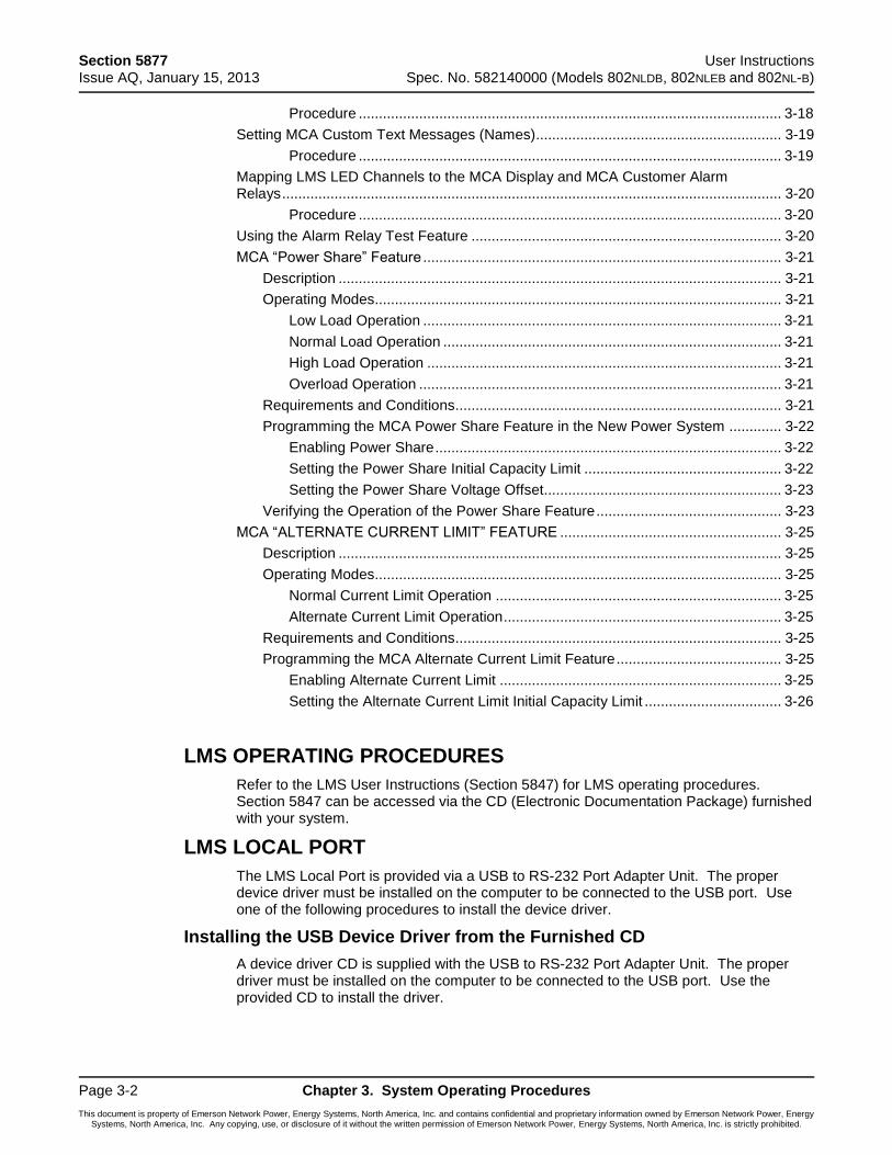
Section 5877 User Instructions Issue AQ, January 15, 2013 Spec. No. 582140000 (Models 802NLDB, 802NLEB and 802NL-B)
Page 3-2 Chapter 3. System Operating Procedures
This document is property of Emerson Network Power, Energy Systems, North America, Inc. and contains confidential and proprietary information owned by Emerson Network Power, Energy Systems, North America, Inc. Any copying, use, or disclosure of it without the written permission of Emerson Network Power, Energy Systems, North America, Inc. is strictly prohibited.
Procedure ......................................................................................................... 3-18
Setting MCA Custom Text Messages (Names) ............................................................. 3-19
Procedure ......................................................................................................... 3-19
Mapping LMS LED Channels to the MCA Display and MCA Customer Alarm Relays ............................................................................................................................ 3-20
Procedure ......................................................................................................... 3-20
Using the Alarm Relay Test Feature ............................................................................. 3-20
MCA “Power Share” Feature ......................................................................................... 3-21
Description .............................................................................................................. 3-21
Operating Modes..................................................................................................... 3-21
Low Load Operation ......................................................................................... 3-21
Normal Load Operation .................................................................................... 3-21
High Load Operation ........................................................................................ 3-21
Overload Operation .......................................................................................... 3-21
Requirements and Conditions ................................................................................. 3-21
Programming the MCA Power Share Feature in the New Power System ............. 3-22
Enabling Power Share ...................................................................................... 3-22
Setting the Power Share Initial Capacity Limit ................................................. 3-22
Setting the Power Share Voltage Offset........................................................... 3-23
Verifying the Operation of the Power Share Feature .............................................. 3-23
MCA “ALTERNATE CURRENT LIMIT” FEATURE ....................................................... 3-25
Description .............................................................................................................. 3-25
Operating Modes..................................................................................................... 3-25
Normal Current Limit Operation ....................................................................... 3-25
Alternate Current Limit Operation ..................................................................... 3-25
Requirements and Conditions ................................................................................. 3-25
Programming the MCA Alternate Current Limit Feature ......................................... 3-25
Enabling Alternate Current Limit ...................................................................... 3-25
Setting the Alternate Current Limit Initial Capacity Limit .................................. 3-26
LMS OPERATING PROCEDURES
Refer to the LMS User Instructions (Section 5847) for LMS operating procedures. Section 5847 can be accessed via the CD (Electronic Documentation Package) furnished with your system.
LMS LOCAL PORT
The LMS Local Port is provided via a USB to RS-232 Port Adapter Unit. The proper device driver must be installed on the computer to be connected to the USB port. Use one of the following procedures to install the device driver.
Installing the USB Device Driver from the Furnished CD
A device driver CD is supplied with the USB to RS-232 Port Adapter Unit. The proper driver must be installed on the computer to be connected to the USB port. Use the provided CD to install the driver.
User Instructions Section 5877 Spec. No. 582140000 (Models 802NLDB, 802NLEB and 802NL-B) Issue AQ, January 15, 2013
Chapter 3. System Operating Procedures Page 3-3
This document is property of Emerson Network Power, Energy Systems, North America, Inc. and contains confidential and proprietary information owned by Emerson Network Power, Energy Systems, North America, Inc. Any copying, use, or disclosure of it without the written permission of Emerson Network Power, Energy Systems, North America, Inc. is strictly prohibited.
Downloading the USB Driver from the Web
1) Go to this link http://vscom.de/downloadcenter.htm.
2) Select “USB to Serial Drivers” from the Product Category drop-down menu.
3) Select your product model’s “Driver and Documentation” to download the files.
4) Select your computer’s operating system.
5) Run or save the application.
Setting up your Computer to Access the Power System
1) Select Hyper terminal.
2) Connect using one of the unused COM ports. (e.g. COM 5)
3) Set Bit Per Second to 19200.
4) Set Data Bits to 8.
5) Set Parity to None.
6) Set Stop bits to 1.
7) Set Flow control to Hardware.
8) Select OK.
9) In Hyper terminal press ENTER.
10) Enter the password 6.
11) Enter “?” to see commands.
LOCAL CONTROLS AND INDICATORS
Location and Identification
Refer to the illustrations in Chapter 1. System Overview.
LMS Main/Expansion CPU Circuit Card (if furnished) Controls and Indicators
Refer to the LMS User Instructions (Section 5847). Section 5847 can be accessed via the CD (Electronic Documentation Package) furnished with your system.
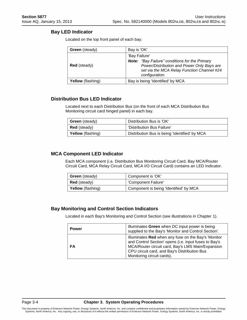
Section 5877 User Instructions Issue AQ, January 15, 2013 Spec. No. 582140000 (Models 802NLDB, 802NLEB and 802NL-B)
Page 3-4 Chapter 3. System Operating Procedures
This document is property of Emerson Network Power, Energy Systems, North America, Inc. and contains confidential and proprietary information owned by Emerson Network Power, Energy Systems, North America, Inc. Any copying, use, or disclosure of it without the written permission of Emerson Network Power, Energy Systems, North America, Inc. is strictly prohibited.
Bay LED Indicator
Located on the top front panel of each bay.
Green (steady) Bay is 'OK'
Red (steady)
'Bay Failure'
Note: “Bay Failure” conditions for the Primary Power/Distribution and Power Only Bays are set via the MCA Relay Function Channel #24 configuration.
Yellow (flashing) Bay is being 'Identified' by MCA
Distribution Bus LED Indicator
Located next to each Distribution Bus (on the front of each MCA Distribution Bus Monitoring circuit card hinged panel) in each bay.
Green (steady) Distribution Bus is 'OK'
Red (steady) 'Distribution Bus Failure'
Yellow (flashing) Distribution Bus is being 'Identified' by MCA
MCA Component LED Indicator
Each MCA component (i.e. Distribution Bus Monitoring Circuit Card, Bay MCA/Router Circuit Card, MCA Relay Circuit Card, MCA I/O Circuit Card) contains an LED Indicator.
Green (steady) Component is 'OK'
Red (steady) 'Component Failure'
Yellow (flashing) Component is being 'Identified' by MCA
Bay Monitoring and Control Section Indicators
Located in each Bay's Monitoring and Control Section (see illustrations in Chapter 1).
Power Illuminates Green when DC input power is being supplied to the Bay's 'Monitor and Control Section'.
FA
Illuminates Red when any fuse on the Bay's 'Monitor and Control Section' opens (i.e. input fuses to Bay's MCA/Router circuit card, Bay's LMS Main/Expansion CPU circuit card, and Bay's Distribution Bus Monitoring circuit cards).
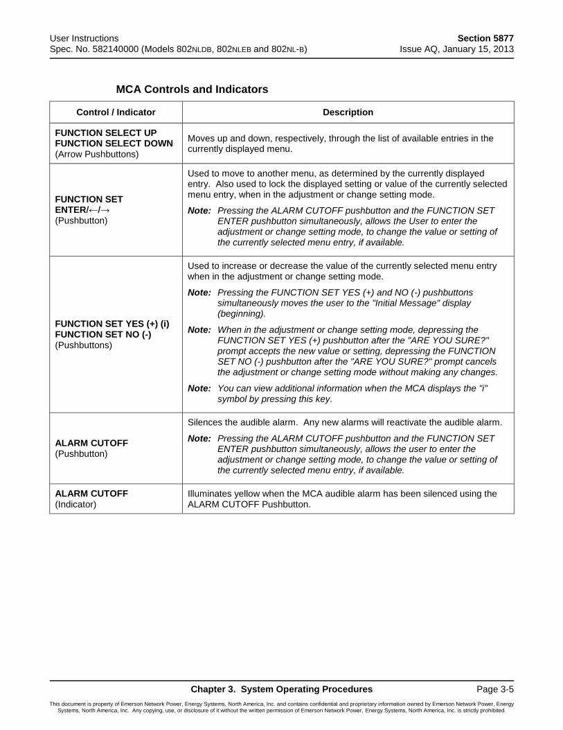
User Instructions Section 5877 Spec. No. 582140000 (Models 802NLDB, 802NLEB and 802NL-B) Issue AQ, January 15, 2013
Chapter 3. System Operating Procedures Page 3-5
This document is property of Emerson Network Power, Energy Systems, North America, Inc. and contains confidential and proprietary information owned by Emerson Network Power, Energy Systems, North America, Inc. Any copying, use, or disclosure of it without the written permission of Emerson Network Power, Energy Systems, North America, Inc. is strictly prohibited.
MCA Controls and Indicators
Control / Indicator Description
FUNCTION SELECT UP FUNCTION SELECT DOWN (Arrow Pushbuttons)
Moves up and down, respectively, through the list of available entries in the currently displayed menu.
FUNCTION SET ENTER/←/→ (Pushbutton)
Used to move to another menu, as determined by the currently displayed entry. Also used to lock the displayed setting or value of the currently selected menu entry, when in the adjustment or change setting mode.
Note: Pressing the ALARM CUTOFF pushbutton and the FUNCTION SET ENTER pushbutton simultaneously, allows the User to enter the adjustment or change setting mode, to change the value or setting of the currently selected menu entry, if available.
FUNCTION SET YES (+) (i) FUNCTION SET NO (-) (Pushbuttons)
Used to increase or decrease the value of the currently selected menu entry when in the adjustment or change setting mode.
Note: Pressing the FUNCTION SET YES (+) and NO (-) pushbuttons simultaneously moves the user to the "Initial Message" display (beginning).
Note: When in the adjustment or change setting mode, depressing the FUNCTION SET YES (+) pushbutton after the "ARE YOU SURE?" prompt accepts the new value or setting, depressing the FUNCTION SET NO (-) pushbutton after the "ARE YOU SURE?" prompt cancels the adjustment or change setting mode without making any changes.
Note: You can view additional information when the MCA displays the "i" symbol by pressing this key.
ALARM CUTOFF (Pushbutton)
Silences the audible alarm. Any new alarms will reactivate the audible alarm.
Note: Pressing the ALARM CUTOFF pushbutton and the FUNCTION SET ENTER pushbutton simultaneously, allows the user to enter the adjustment or change setting mode, to change the value or setting of the currently selected menu entry, if available.
ALARM CUTOFF (Indicator)
Illuminates yellow when the MCA audible alarm has been silenced using the ALARM CUTOFF Pushbutton.
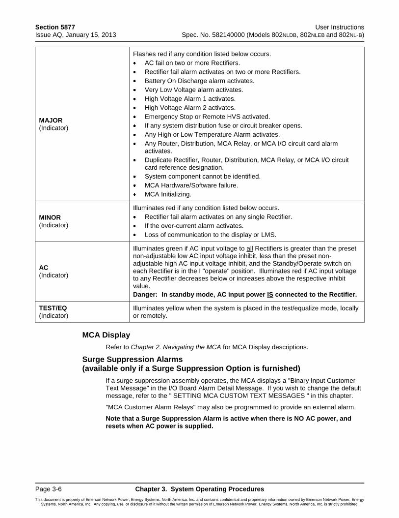
Section 5877 User Instructions Issue AQ, January 15, 2013 Spec. No. 582140000 (Models 802NLDB, 802NLEB and 802NL-B)
Page 3-6 Chapter 3. System Operating Procedures
This document is property of Emerson Network Power, Energy Systems, North America, Inc. and contains confidential and proprietary information owned by Emerson Network Power, Energy Systems, North America, Inc. Any copying, use, or disclosure of it without the written permission of Emerson Network Power, Energy Systems, North America, Inc. is strictly prohibited.
MAJOR (Indicator)
Flashes red if any condition listed below occurs.
AC fail on two or more Rectifiers.
Rectifier fail alarm activates on two or more Rectifiers.
Battery On Discharge alarm activates.
Very Low Voltage alarm activates.
High Voltage Alarm 1 activates.
High Voltage Alarm 2 activates.
Emergency Stop or Remote HVS activated.
If any system distribution fuse or circuit breaker opens.
Any High or Low Temperature Alarm activates.
Any Router, Distribution, MCA Relay, or MCA I/O circuit card alarm activates.
Duplicate Rectifier, Router, Distribution, MCA Relay, or MCA I/O circuit card reference designation.
System component cannot be identified.
MCA Hardware/Software failure.
MCA Initializing.
MINOR (Indicator)
Illuminates red if any condition listed below occurs.
Rectifier fail alarm activates on any single Rectifier.
If the over-current alarm activates.
Loss of communication to the display or LMS.
AC (Indicator)
Illuminates green if AC input voltage to all Rectifiers is greater than the preset non-adjustable low AC input voltage inhibit, less than the preset non-adjustable high AC input voltage inhibit, and the Standby/Operate switch on each Rectifier is in the I "operate" position. Illuminates red if AC input voltage to any Rectifier decreases below or increases above the respective inhibit value.
Danger: In standby mode, AC input power IS connected to the Rectifier.
TEST/EQ (Indicator)
Illuminates yellow when the system is placed in the test/equalize mode, locally or remotely.
MCA Display
Refer to Chapter 2. Navigating the MCA for MCA Display descriptions.
Surge Suppression Alarms (available only if a Surge Suppression Option is furnished)
If a surge suppression assembly operates, the MCA displays a "Binary Input Customer Text Message" in the I/O Board Alarm Detail Message. If you wish to change the default message, refer to the " SETTING MCA CUSTOM TEXT MESSAGES " in this chapter.
"MCA Customer Alarm Relays" may also be programmed to provide an external alarm.
Note that a Surge Suppression Alarm is active when there is NO AC power, and resets when AC power is supplied.
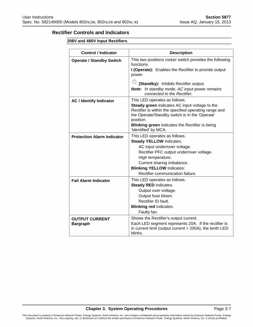
User Instructions Section 5877 Spec. No. 582140000 (Models 802NLDB, 802NLEB and 802NL-B) Issue AQ, January 15, 2013
Chapter 3. System Operating Procedures Page 3-7
This document is property of Emerson Network Power, Energy Systems, North America, Inc. and contains confidential and proprietary information owned by Emerson Network Power, Energy Systems, North America, Inc. Any copying, use, or disclosure of it without the written permission of Emerson Network Power, Energy Systems, North America, Inc. is strictly prohibited.
Rectifier Controls and Indicators
208V and 480V Input Rectifiers
Control / Indicator Description
Operate / Standby Switch This two positions rocker switch provides the following functions.
I (Operate): Enables the Rectifier to provide output power.
(Standby): Inhibits Rectifier output.
Note: In standby mode, AC input power remains connected to the Rectifier.
AC / Identify Indicator This LED operates as follows.
Steady green indicates AC input voltage to the Rectifier is within the specified operating range and the Operate/Standby switch is in the 'Operate' position.
Blinking green indicates the Rectifier is being 'Identified' by MCA.
Protection Alarm Indicator This LED operates as follows.
Steady YELLOW indicates.
AC input under/over voltage.
Rectifier PFC output under/over voltage.
High temperature.
Current sharing imbalance.
Blinking YELLOW indicates:
Rectifier communication failure.
Fail Alarm Indicator This LED operates as follows.
Steady RED indicates.
Output over-voltage.
Output fuse blown.
Rectifier ID fault.
Blinking red indicates:
Faulty fan.
OUTPUT CURRENT Bargraph
Shows the Rectifier's output current.
Each LED segment represents 20A. If the rectifier is in current limit (output current > 200A), the tenth LED blinks.
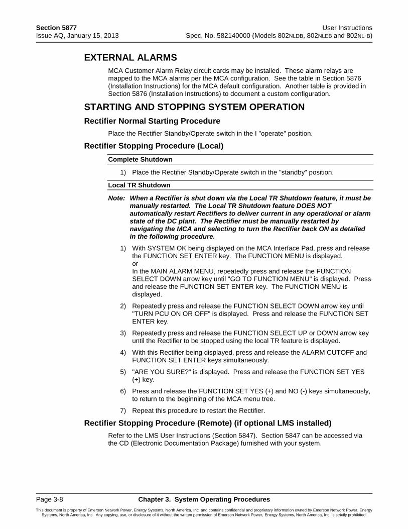
Section 5877 User Instructions Issue AQ, January 15, 2013 Spec. No. 582140000 (Models 802NLDB, 802NLEB and 802NL-B)
Page 3-8 Chapter 3. System Operating Procedures
This document is property of Emerson Network Power, Energy Systems, North America, Inc. and contains confidential and proprietary information owned by Emerson Network Power, Energy Systems, North America, Inc. Any copying, use, or disclosure of it without the written permission of Emerson Network Power, Energy Systems, North America, Inc. is strictly prohibited.
EXTERNAL ALARMS
MCA Customer Alarm Relay circuit cards may be installed. These alarm relays are mapped to the MCA alarms per the MCA configuration. See the table in Section 5876 (Installation Instructions) for the MCA default configuration. Another table is provided in Section 5876 (Installation Instructions) to document a custom configuration.
STARTING AND STOPPING SYSTEM OPERATION
Rectifier Normal Starting Procedure
Place the Rectifier Standby/Operate switch in the I "operate" position.
Rectifier Stopping Procedure (Local)
Complete Shutdown
1) Place the Rectifier Standby/Operate switch in the "standby" position.
Local TR Shutdown
Note: When a Rectifier is shut down via the Local TR Shutdown feature, it must be manually restarted. The Local TR Shutdown feature DOES NOT automatically restart Rectifiers to deliver current in any operational or alarm state of the DC plant. The Rectifier must be manually restarted by navigating the MCA and selecting to turn the Rectifier back ON as detailed in the following procedure.
1) With SYSTEM OK being displayed on the MCA Interface Pad, press and release the FUNCTION SET ENTER key. The FUNCTION MENU is displayed. or In the MAIN ALARM MENU, repeatedly press and release the FUNCTION SELECT DOWN arrow key until "GO TO FUNCTION MENU" is displayed. Press and release the FUNCTION SET ENTER key. The FUNCTION MENU is displayed.
2) Repeatedly press and release the FUNCTION SELECT DOWN arrow key until "TURN PCU ON OR OFF" is displayed. Press and release the FUNCTION SET ENTER key.
3) Repeatedly press and release the FUNCTION SELECT UP or DOWN arrow key until the Rectifier to be stopped using the local TR feature is displayed.
4) With this Rectifier being displayed, press and release the ALARM CUTOFF and FUNCTION SET ENTER keys simultaneously.
5) "ARE YOU SURE?" is displayed. Press and release the FUNCTION SET YES (+) key.
6) Press and release the FUNCTION SET YES (+) and NO (-) keys simultaneously, to return to the beginning of the MCA menu tree.
7) Repeat this procedure to restart the Rectifier.
Rectifier Stopping Procedure (Remote) (if optional LMS installed)
Refer to the LMS User Instructions (Section 5847). Section 5847 can be accessed via the CD (Electronic Documentation Package) furnished with your system.
User Instructions Section 5877 Spec. No. 582140000 (Models 802NLDB, 802NLEB and 802NL-B) Issue AQ, January 15, 2013
Chapter 3. System Operating Procedures Page 3-9
This document is property of Emerson Network Power, Energy Systems, North America, Inc. and contains confidential and proprietary information owned by Emerson Network Power, Energy Systems, North America, Inc. Any copying, use, or disclosure of it without the written permission of Emerson Network Power, Energy Systems, North America, Inc. is strictly prohibited.
RESTARTING PROCEDURES WHEN RECTIFIER IS AUTOMATICALLY OR MANUALLY INHIBITED, SHUT DOWN, OR LOCKED OUT
Rectifier High Voltage Shutdown Lockout
Place the Standby/Operate switch to the "standby" position, and then back to the I "operate" position.
Rectifier Emergency Shutdown and Fire Alarm Disconnect
Remove the emergency shutdown and fire alarm disconnect signal, and on each Rectifier place the Standby/Operate switch to the "standby" position and then back to the I "operate" position.
Remote On/Off (TR)
Remove the remote on/off (TR) signal from the respective Rectifier. The signal can originate from the LMS (if installed), or via the local MCA Control Panel.
OUTPUT VOLTAGE MODE OF OPERATION SELECTION
Placing the System into the Float Mode of Operation
Manually place the system into float mode by navigating to and activating the "TEST/EQ MODE ACTIVE. SET FLOAT?" menu item in the MCA function menu. A step-by-step procedure is provided next.
1) With SYSTEM OK being displayed on the MCA Interface Pad, press and release the FUNCTION SET ENTER key. The FUNCTION MENU is displayed. or In the MAIN ALARM MENU, repeatedly press and release the FUNCTION SELECT DOWN arrow key until "GO TO FUNCTION MENU" is displayed. Press and release the FUNCTION SET ENTER key. The FUNCTION MENU is displayed.
Note: In the following step, if "FLOAT MODE IS ACTIVE. SET TEST/EQ?" is displayed, the system is already operating in the float mode. In this case, DO NOT perform steps 2) through 4), proceed with step 5).
2) Press and release the FUNCTION SELECT DOWN arrow key to display "TEST/EQ MODE ACTIVE. SET FLOAT?".
3) Press and release the ALARM CUTOFF and FUNCTION SET ENTER keys simultaneously.
4) "ARE YOU SURE?" is displayed. Press and release the FUNCTION SET YES (+) key.
5) Press and release the FUNCTION SET YES (+) and NO (-) keys simultaneously, to return to the beginning of the MCA menu tree.
Section 5877 User Instructions Issue AQ, January 15, 2013 Spec. No. 582140000 (Models 802NLDB, 802NLEB and 802NL-B)
Page 3-10 Chapter 3. System Operating Procedures
This document is property of Emerson Network Power, Energy Systems, North America, Inc. and contains confidential and proprietary information owned by Emerson Network Power, Energy Systems, North America, Inc. Any copying, use, or disclosure of it without the written permission of Emerson Network Power, Energy Systems, North America, Inc. is strictly prohibited.
Placing the System into the Test/Equalize Mode of Operation
Warning: Do not supply equalize output voltage for a longer period than necessary. Prolonged higher battery charge voltage overcharges the battery cells and reduces battery life.
Note: Test/Equalize Mode requires Power Share to be turned off.
There are four methods of placing the system from the float mode to the test/equalize mode.
Method 1 (Manual Test/Equalize) Procedure
In this method, a user manually places the system into the test/equalize mode via the MCA Control Panel. A user must manually return the system to the float mode via the MCA Control Panel. Follow the procedures described below.
Setting for Manual Test/Equalize: Set the "MANUAL TEST/EQUALIZE = hh HOURS" menu item in the MCA configure menu to below 0. The display changes to "TEST/EQUALIZE STOP IS MANUAL" to indicate manual test/equalize mode is set. A step-by-step procedure is provided next.
1) With SYSTEM OK being displayed on the MCA Interface Pad, press and release the FUNCTION SET ENTER key. The FUNCTION MENU is displayed. or In the MAIN ALARM MENU, repeatedly press and release the FUNCTION SELECT DOWN arrow key until "GO TO FUNCTION MENU" is displayed. Press and release the FUNCTION SET ENTER key. The FUNCTION MENU is displayed.
2) Repeatedly press and release the FUNCTION SELECT DOWN arrow key until "CHANGE CONFIGURATION PARAMETERS" is displayed. Press and release the FUNCTION SET ENTER key.
3) Press and release the FUNCTION SELECT DOWN arrow key to display "MANUAL TEST/EQUALIZE = hh HOURS" or "TEST/EQUALIZE STOP IS MANUAL" is displayed.
Note: If "TEST/EQUALIZE STOP IS MANUAL" is displayed, the system is already set for manual test/equalize. In this case, proceed with step 8).
Note: If "END TEST/EQUALIZE IN hhh.hh HOURS" is displayed, the system is set for manually initiated timed test/equalize, and a timed test/equalize is in progress. In this case, you can proceed with steps 4) through 7) to cancel the timed test/equalize in progress and change the current setting, or proceed with step 8) to proceed with the timed test/equalize in progress and make no changes.
4) Press and release the ALARM CUTOFF and FUNCTION SET ENTER keys simultaneously.
5) Press the FUNCTION SET NO / - key to scroll the displayed value towards 0. Release the key when "TEST/EQUALIZE STOP IS MANUAL" is displayed. This indicates the manually initiated timed test/equalize feature is disabled and the system must be manually returned to the float mode if placed in the test/equalize mode.
6) Press and release the FUNCTION SET ENTER key.
7) “ARE YOU SURE?” is displayed. Press and release the FUNCTION SET YES (+) key.
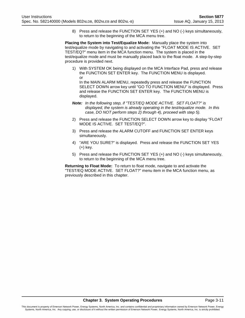
User Instructions Section 5877 Spec. No. 582140000 (Models 802NLDB, 802NLEB and 802NL-B) Issue AQ, January 15, 2013
Chapter 3. System Operating Procedures Page 3-11
This document is property of Emerson Network Power, Energy Systems, North America, Inc. and contains confidential and proprietary information owned by Emerson Network Power, Energy Systems, North America, Inc. Any copying, use, or disclosure of it without the written permission of Emerson Network Power, Energy Systems, North America, Inc. is strictly prohibited.
8) Press and release the FUNCTION SET YES (+) and NO (-) keys simultaneously, to return to the beginning of the MCA menu tree.
Placing the System into Test/Equalize Mode: Manually place the system into test/equalize mode by navigating to and activating the "FLOAT MODE IS ACTIVE. SET TEST/EQ?" menu item in the MCA function menu. The system is placed in the test/equalize mode and must be manually placed back to the float mode. A step-by-step procedure is provided next.
1) With SYSTEM OK being displayed on the MCA Interface Pad, press and release the FUNCTION SET ENTER key. The FUNCTION MENU is displayed. or In the MAIN ALARM MENU, repeatedly press and release the FUNCTION SELECT DOWN arrow key until "GO TO FUNCTION MENU" is displayed. Press and release the FUNCTION SET ENTER key. The FUNCTION MENU is displayed.
Note: In the following step, if "TEST/EQ MODE ACTIVE. SET FLOAT?" is displayed, the system is already operating in the test/equalize mode. In this case, DO NOT perform steps 2) through 4), proceed with step 5).
2) Press and release the FUNCTION SELECT DOWN arrow key to display "FLOAT MODE IS ACTIVE. SET TEST/EQ?".
3) Press and release the ALARM CUTOFF and FUNCTION SET ENTER keys simultaneously.
4) "ARE YOU SURE?" is displayed. Press and release the FUNCTION SET YES (+) key.
5) Press and release the FUNCTION SET YES (+) and NO (-) keys simultaneously, to return to the beginning of the MCA menu tree.
Returning to Float Mode: To return to float mode, navigate to and activate the "TEST/EQ MODE ACTIVE. SET FLOAT?" menu item in the MCA function menu, as previously described in this chapter.
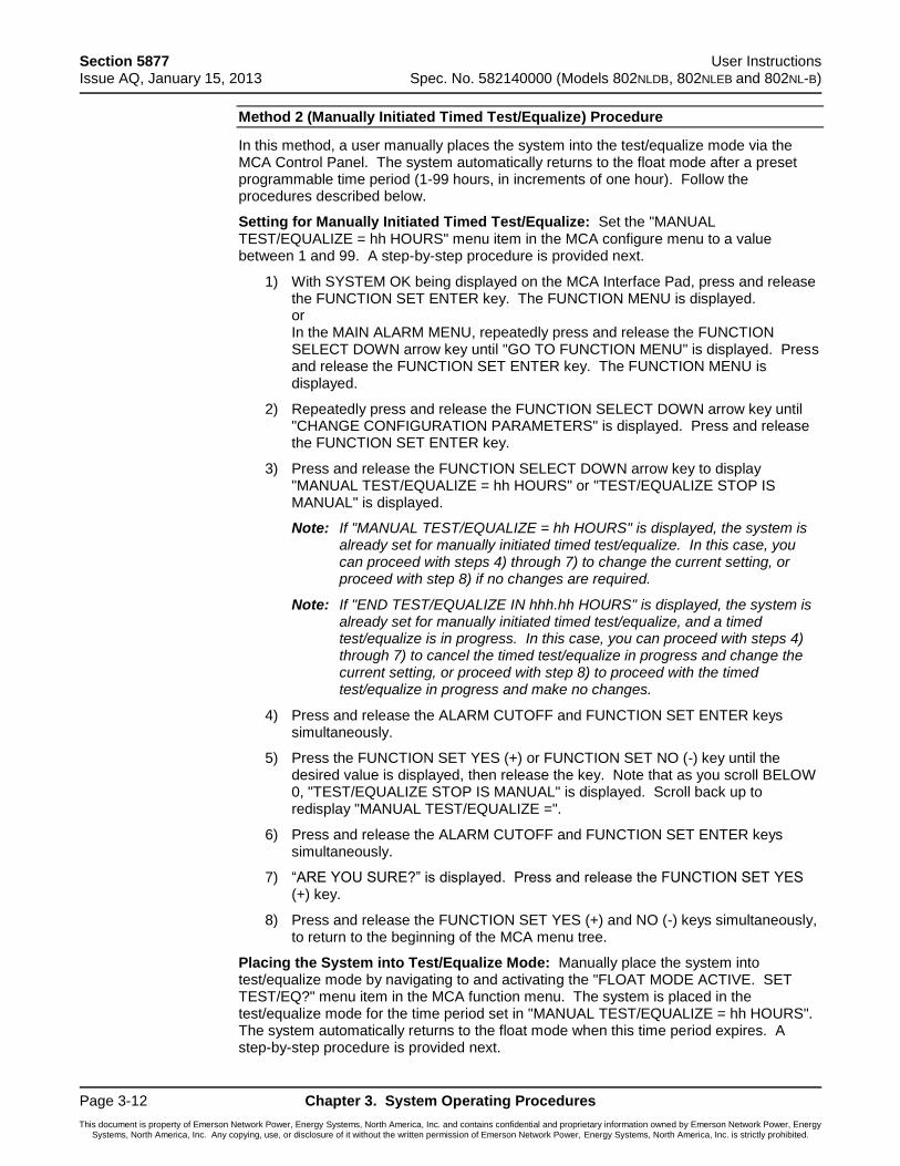
Section 5877 User Instructions Issue AQ, January 15, 2013 Spec. No. 582140000 (Models 802NLDB, 802NLEB and 802NL-B)
Page 3-12 Chapter 3. System Operating Procedures
This document is property of Emerson Network Power, Energy Systems, North America, Inc. and contains confidential and proprietary information owned by Emerson Network Power, Energy Systems, North America, Inc. Any copying, use, or disclosure of it without the written permission of Emerson Network Power, Energy Systems, North America, Inc. is strictly prohibited.
Method 2 (Manually Initiated Timed Test/Equalize) Procedure
In this method, a user manually places the system into the test/equalize mode via the MCA Control Panel. The system automatically returns to the float mode after a preset programmable time period (1-99 hours, in increments of one hour). Follow the procedures described below.
Setting for Manually Initiated Timed Test/Equalize: Set the "MANUAL TEST/EQUALIZE = hh HOURS" menu item in the MCA configure menu to a value between 1 and 99. A step-by-step procedure is provided next.
1) With SYSTEM OK being displayed on the MCA Interface Pad, press and release the FUNCTION SET ENTER key. The FUNCTION MENU is displayed. or In the MAIN ALARM MENU, repeatedly press and release the FUNCTION SELECT DOWN arrow key until "GO TO FUNCTION MENU" is displayed. Press and release the FUNCTION SET ENTER key. The FUNCTION MENU is displayed.
2) Repeatedly press and release the FUNCTION SELECT DOWN arrow key until "CHANGE CONFIGURATION PARAMETERS" is displayed. Press and release the FUNCTION SET ENTER key.
3) Press and release the FUNCTION SELECT DOWN arrow key to display "MANUAL TEST/EQUALIZE = hh HOURS" or "TEST/EQUALIZE STOP IS MANUAL" is displayed.
Note: If "MANUAL TEST/EQUALIZE = hh HOURS" is displayed, the system is already set for manually initiated timed test/equalize. In this case, you can proceed with steps 4) through 7) to change the current setting, or proceed with step 8) if no changes are required.
Note: If "END TEST/EQUALIZE IN hhh.hh HOURS" is displayed, the system is already set for manually initiated timed test/equalize, and a timed test/equalize is in progress. In this case, you can proceed with steps 4) through 7) to cancel the timed test/equalize in progress and change the current setting, or proceed with step 8) to proceed with the timed test/equalize in progress and make no changes.
4) Press and release the ALARM CUTOFF and FUNCTION SET ENTER keys simultaneously.
5) Press the FUNCTION SET YES (+) or FUNCTION SET NO (-) key until the desired value is displayed, then release the key. Note that as you scroll BELOW 0, "TEST/EQUALIZE STOP IS MANUAL" is displayed. Scroll back up to redisplay "MANUAL TEST/EQUALIZE =".
6) Press and release the ALARM CUTOFF and FUNCTION SET ENTER keys simultaneously.
7) “ARE YOU SURE?” is displayed. Press and release the FUNCTION SET YES (+) key.
8) Press and release the FUNCTION SET YES (+) and NO (-) keys simultaneously, to return to the beginning of the MCA menu tree.
Placing the System into Test/Equalize Mode: Manually place the system into test/equalize mode by navigating to and activating the "FLOAT MODE ACTIVE. SET TEST/EQ?" menu item in the MCA function menu. The system is placed in the test/equalize mode for the time period set in "MANUAL TEST/EQUALIZE = hh HOURS". The system automatically returns to the float mode when this time period expires. A step-by-step procedure is provided next.
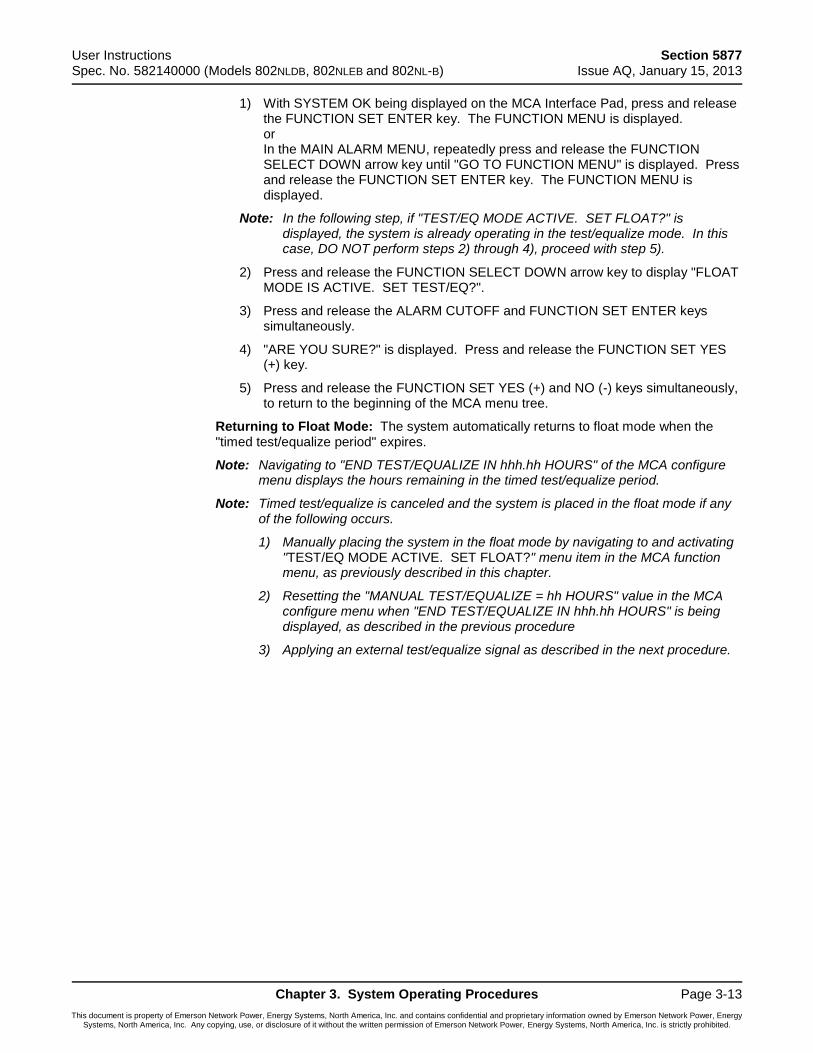
User Instructions Section 5877 Spec. No. 582140000 (Models 802NLDB, 802NLEB and 802NL-B) Issue AQ, January 15, 2013
Chapter 3. System Operating Procedures Page 3-13
This document is property of Emerson Network Power, Energy Systems, North America, Inc. and contains confidential and proprietary information owned by Emerson Network Power, Energy Systems, North America, Inc. Any copying, use, or disclosure of it without the written permission of Emerson Network Power, Energy Systems, North America, Inc. is strictly prohibited.
1) With SYSTEM OK being displayed on the MCA Interface Pad, press and release the FUNCTION SET ENTER key. The FUNCTION MENU is displayed. or In the MAIN ALARM MENU, repeatedly press and release the FUNCTION SELECT DOWN arrow key until "GO TO FUNCTION MENU" is displayed. Press and release the FUNCTION SET ENTER key. The FUNCTION MENU is displayed.
Note: In the following step, if "TEST/EQ MODE ACTIVE. SET FLOAT?" is displayed, the system is already operating in the test/equalize mode. In this case, DO NOT perform steps 2) through 4), proceed with step 5).
2) Press and release the FUNCTION SELECT DOWN arrow key to display "FLOAT MODE IS ACTIVE. SET TEST/EQ?".
3) Press and release the ALARM CUTOFF and FUNCTION SET ENTER keys simultaneously.
4) "ARE YOU SURE?" is displayed. Press and release the FUNCTION SET YES (+) key.
5) Press and release the FUNCTION SET YES (+) and NO (-) keys simultaneously, to return to the beginning of the MCA menu tree.
Returning to Float Mode: The system automatically returns to float mode when the "timed test/equalize period" expires.
Note: Navigating to "END TEST/EQUALIZE IN hhh.hh HOURS" of the MCA configure menu displays the hours remaining in the timed test/equalize period.
Note: Timed test/equalize is canceled and the system is placed in the float mode if any of the following occurs.
1) Manually placing the system in the float mode by navigating to and activating "TEST/EQ MODE ACTIVE. SET FLOAT?" menu item in the MCA function menu, as previously described in this chapter.
2) Resetting the "MANUAL TEST/EQUALIZE = hh HOURS" value in the MCA configure menu when "END TEST/EQUALIZE IN hhh.hh HOURS" is being displayed, as described in the previous procedure
3) Applying an external test/equalize signal as described in the next procedure.
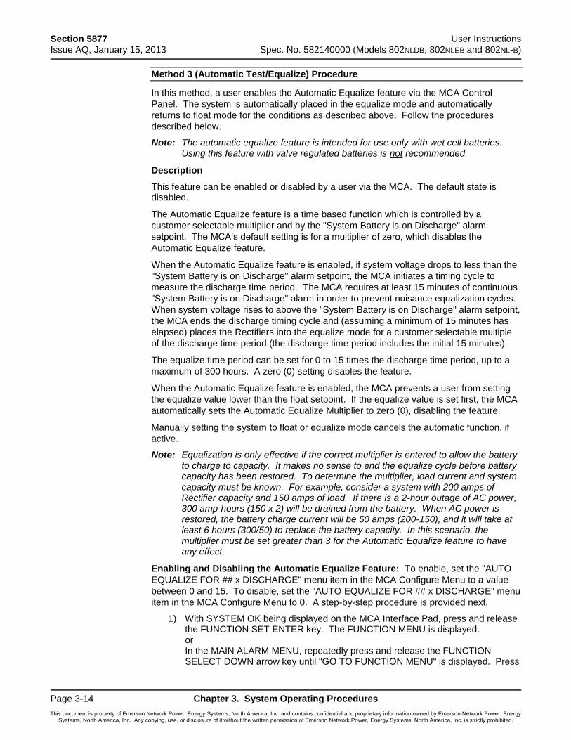
Section 5877 User Instructions Issue AQ, January 15, 2013 Spec. No. 582140000 (Models 802NLDB, 802NLEB and 802NL-B)
Page 3-14 Chapter 3. System Operating Procedures
This document is property of Emerson Network Power, Energy Systems, North America, Inc. and contains confidential and proprietary information owned by Emerson Network Power, Energy Systems, North America, Inc. Any copying, use, or disclosure of it without the written permission of Emerson Network Power, Energy Systems, North America, Inc. is strictly prohibited.
Method 3 (Automatic Test/Equalize) Procedure
In this method, a user enables the Automatic Equalize feature via the MCA Control
Panel. The system is automatically placed in the equalize mode and automatically
returns to float mode for the conditions as described above. Follow the procedures
described below.
Note: The automatic equalize feature is intended for use only with wet cell batteries. Using this feature with valve regulated batteries is not recommended.
Description
This feature can be enabled or disabled by a user via the MCA. The default state is disabled.
The Automatic Equalize feature is a time based function which is controlled by a
customer selectable multiplier and by the "System Battery is on Discharge" alarm
setpoint. The MCA’s default setting is for a multiplier of zero, which disables the
Automatic Equalize feature.
When the Automatic Equalize feature is enabled, if system voltage drops to less than the
"System Battery is on Discharge" alarm setpoint, the MCA initiates a timing cycle to
measure the discharge time period. The MCA requires at least 15 minutes of continuous
"System Battery is on Discharge" alarm in order to prevent nuisance equalization cycles.
When system voltage rises to above the "System Battery is on Discharge" alarm setpoint,
the MCA ends the discharge timing cycle and (assuming a minimum of 15 minutes has
elapsed) places the Rectifiers into the equalize mode for a customer selectable multiple
of the discharge time period (the discharge time period includes the initial 15 minutes).
The equalize time period can be set for 0 to 15 times the discharge time period, up to a
maximum of 300 hours. A zero (0) setting disables the feature.
When the Automatic Equalize feature is enabled, the MCA prevents a user from setting
the equalize value lower than the float setpoint. If the equalize value is set first, the MCA
automatically sets the Automatic Equalize Multiplier to zero (0), disabling the feature.
Manually setting the system to float or equalize mode cancels the automatic function, if
active.
Note: Equalization is only effective if the correct multiplier is entered to allow the battery to charge to capacity. It makes no sense to end the equalize cycle before battery capacity has been restored. To determine the multiplier, load current and system capacity must be known. For example, consider a system with 200 amps of Rectifier capacity and 150 amps of load. If there is a 2-hour outage of AC power, 300 amp-hours (150 x 2) will be drained from the battery. When AC power is restored, the battery charge current will be 50 amps (200-150), and it will take at least 6 hours (300/50) to replace the battery capacity. In this scenario, the multiplier must be set greater than 3 for the Automatic Equalize feature to have any effect.
Enabling and Disabling the Automatic Equalize Feature: To enable, set the "AUTO
EQUALIZE FOR ## x DISCHARGE" menu item in the MCA Configure Menu to a value
between 0 and 15. To disable, set the "AUTO EQUALIZE FOR ## x DISCHARGE" menu
item in the MCA Configure Menu to 0. A step-by-step procedure is provided next.
1) With SYSTEM OK being displayed on the MCA Interface Pad, press and release the FUNCTION SET ENTER key. The FUNCTION MENU is displayed. or In the MAIN ALARM MENU, repeatedly press and release the FUNCTION SELECT DOWN arrow key until "GO TO FUNCTION MENU" is displayed. Press
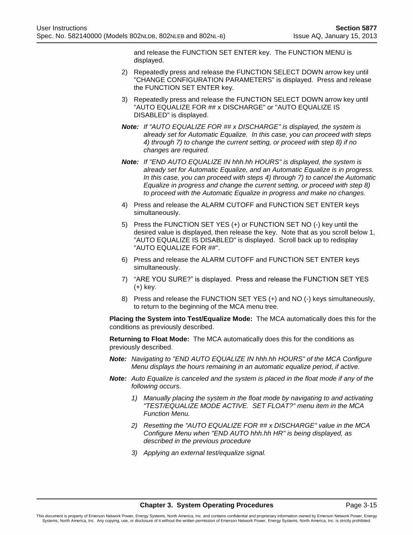
User Instructions Section 5877 Spec. No. 582140000 (Models 802NLDB, 802NLEB and 802NL-B) Issue AQ, January 15, 2013
Chapter 3. System Operating Procedures Page 3-15
This document is property of Emerson Network Power, Energy Systems, North America, Inc. and contains confidential and proprietary information owned by Emerson Network Power, Energy Systems, North America, Inc. Any copying, use, or disclosure of it without the written permission of Emerson Network Power, Energy Systems, North America, Inc. is strictly prohibited.
and release the FUNCTION SET ENTER key. The FUNCTION MENU is displayed.
2) Repeatedly press and release the FUNCTION SELECT DOWN arrow key until "CHANGE CONFIGURATION PARAMETERS" is displayed. Press and release the FUNCTION SET ENTER key.
3) Repeatedly press and release the FUNCTION SELECT DOWN arrow key until "AUTO EQUALIZE FOR ## x DISCHARGE" or "AUTO EQUALIZE IS DISABLED" is displayed.
Note: If "AUTO EQUALIZE FOR ## x DISCHARGE" is displayed, the system is already set for Automatic Equalize. In this case, you can proceed with steps 4) through 7) to change the current setting, or proceed with step 8) if no changes are required.
Note: If "END AUTO EQUALIZE IN hhh.hh HOURS" is displayed, the system is already set for Automatic Equalize, and an Automatic Equalize is in progress. In this case, you can proceed with steps 4) through 7) to cancel the Automatic Equalize in progress and change the current setting, or proceed with step 8) to proceed with the Automatic Equalize in progress and make no changes.
4) Press and release the ALARM CUTOFF and FUNCTION SET ENTER keys simultaneously.
5) Press the FUNCTION SET YES (+) or FUNCTION SET NO (-) key until the desired value is displayed, then release the key. Note that as you scroll below 1, "AUTO EQUALIZE IS DISABLED" is displayed. Scroll back up to redisplay "AUTO EQUALIZE FOR ##".
6) Press and release the ALARM CUTOFF and FUNCTION SET ENTER keys simultaneously.
7) “ARE YOU SURE?” is displayed. Press and release the FUNCTION SET YES (+) key.
8) Press and release the FUNCTION SET YES (+) and NO (-) keys simultaneously, to return to the beginning of the MCA menu tree.
Placing the System into Test/Equalize Mode: The MCA automatically does this for the
conditions as previously described.
Returning to Float Mode: The MCA automatically does this for the conditions as
previously described.
Note: Navigating to "END AUTO EQUALIZE IN hhh.hh HOURS" of the MCA Configure Menu displays the hours remaining in an automatic equalize period, if active.
Note: Auto Equalize is canceled and the system is placed in the float mode if any of the following occurs.
1) Manually placing the system in the float mode by navigating to and activating "TEST/EQUALIZE MODE ACTIVE. SET FLOAT?" menu item in the MCA Function Menu.
2) Resetting the "AUTO EQUALIZE FOR ## x DISCHARGE" value in the MCA Configure Menu when "END AUTO hhh.hh HR" is being displayed, as described in the previous procedure
3) Applying an external test/equalize signal.
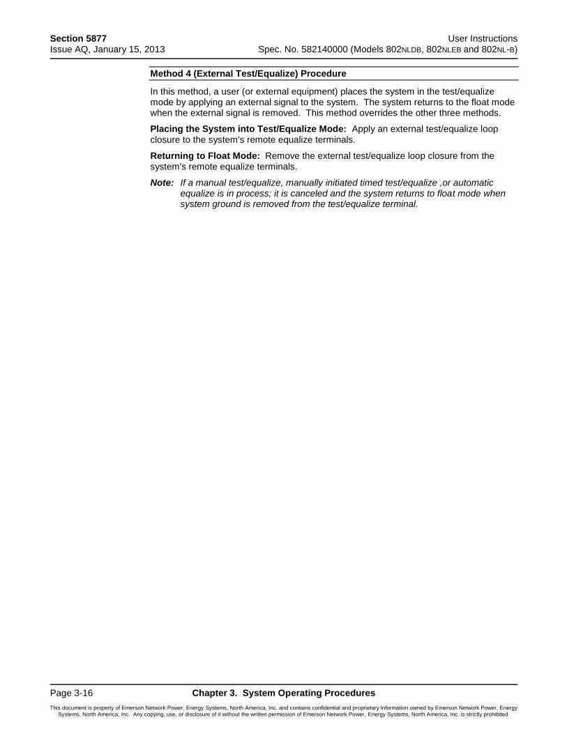
Section 5877 User Instructions Issue AQ, January 15, 2013 Spec. No. 582140000 (Models 802NLDB, 802NLEB and 802NL-B)
Page 3-16 Chapter 3. System Operating Procedures
This document is property of Emerson Network Power, Energy Systems, North America, Inc. and contains confidential and proprietary information owned by Emerson Network Power, Energy Systems, North America, Inc. Any copying, use, or disclosure of it without the written permission of Emerson Network Power, Energy Systems, North America, Inc. is strictly prohibited.
Method 4 (External Test/Equalize) Procedure
In this method, a user (or external equipment) places the system in the test/equalize mode by applying an external signal to the system. The system returns to the float mode when the external signal is removed. This method overrides the other three methods.
Placing the System into Test/Equalize Mode: Apply an external test/equalize loop closure to the system's remote equalize terminals.
Returning to Float Mode: Remove the external test/equalize loop closure from the system's remote equalize terminals.
Note: If a manual test/equalize, manually initiated timed test/equalize ,or automatic equalize is in process; it is canceled and the system returns to float mode when system ground is removed from the test/equalize terminal.
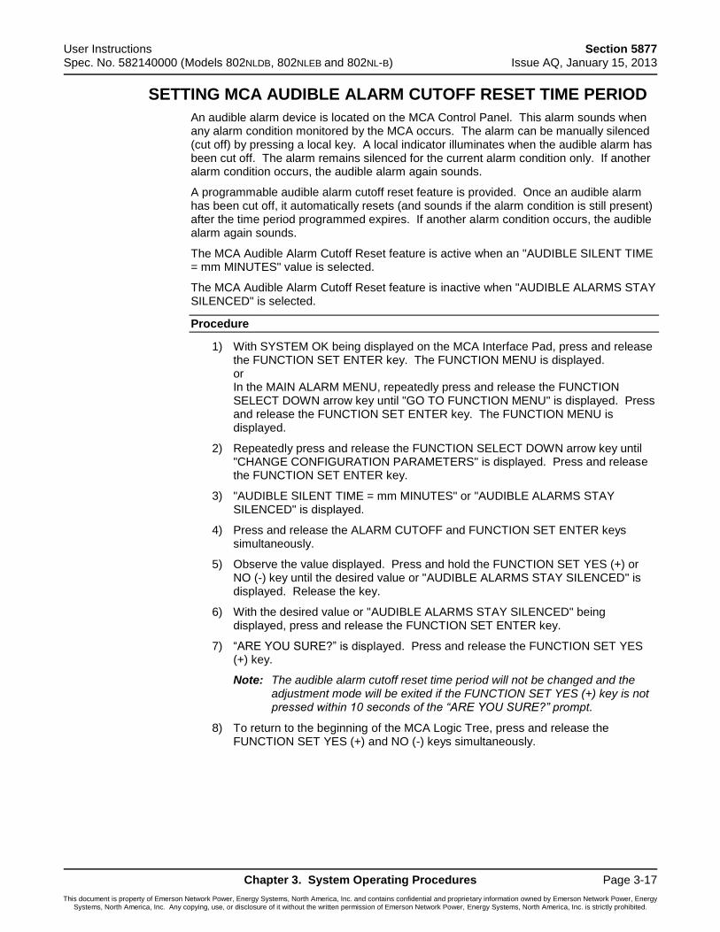
User Instructions Section 5877 Spec. No. 582140000 (Models 802NLDB, 802NLEB and 802NL-B) Issue AQ, January 15, 2013
Chapter 3. System Operating Procedures Page 3-17
This document is property of Emerson Network Power, Energy Systems, North America, Inc. and contains confidential and proprietary information owned by Emerson Network Power, Energy Systems, North America, Inc. Any copying, use, or disclosure of it without the written permission of Emerson Network Power, Energy Systems, North America, Inc. is strictly prohibited.
SETTING MCA AUDIBLE ALARM CUTOFF RESET TIME PERIOD
An audible alarm device is located on the MCA Control Panel. This alarm sounds when any alarm condition monitored by the MCA occurs. The alarm can be manually silenced (cut off) by pressing a local key. A local indicator illuminates when the audible alarm has been cut off. The alarm remains silenced for the current alarm condition only. If another alarm condition occurs, the audible alarm again sounds.
A programmable audible alarm cutoff reset feature is provided. Once an audible alarm has been cut off, it automatically resets (and sounds if the alarm condition is still present) after the time period programmed expires. If another alarm condition occurs, the audible alarm again sounds.
The MCA Audible Alarm Cutoff Reset feature is active when an "AUDIBLE SILENT TIME = mm MINUTES" value is selected.
The MCA Audible Alarm Cutoff Reset feature is inactive when "AUDIBLE ALARMS STAY SILENCED" is selected.
Procedure
1) With SYSTEM OK being displayed on the MCA Interface Pad, press and release the FUNCTION SET ENTER key. The FUNCTION MENU is displayed. or In the MAIN ALARM MENU, repeatedly press and release the FUNCTION SELECT DOWN arrow key until "GO TO FUNCTION MENU" is displayed. Press and release the FUNCTION SET ENTER key. The FUNCTION MENU is displayed.
2) Repeatedly press and release the FUNCTION SELECT DOWN arrow key until "CHANGE CONFIGURATION PARAMETERS" is displayed. Press and release the FUNCTION SET ENTER key.
3) "AUDIBLE SILENT TIME = mm MINUTES" or "AUDIBLE ALARMS STAY SILENCED" is displayed.
4) Press and release the ALARM CUTOFF and FUNCTION SET ENTER keys simultaneously.
5) Observe the value displayed. Press and hold the FUNCTION SET YES (+) or NO (-) key until the desired value or "AUDIBLE ALARMS STAY SILENCED" is displayed. Release the key.
6) With the desired value or "AUDIBLE ALARMS STAY SILENCED" being displayed, press and release the FUNCTION SET ENTER key.
7) “ARE YOU SURE?” is displayed. Press and release the FUNCTION SET YES (+) key.
Note: The audible alarm cutoff reset time period will not be changed and the adjustment mode will be exited if the FUNCTION SET YES (+) key is not pressed within 10 seconds of the “ARE YOU SURE?” prompt.
8) To return to the beginning of the MCA Logic Tree, press and release the FUNCTION SET YES (+) and NO (-) keys simultaneously.
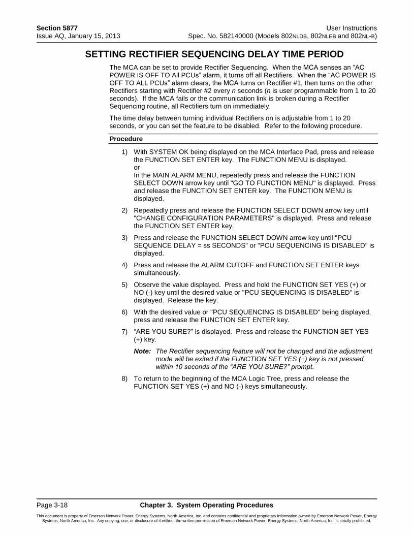
Section 5877 User Instructions Issue AQ, January 15, 2013 Spec. No. 582140000 (Models 802NLDB, 802NLEB and 802NL-B)
Page 3-18 Chapter 3. System Operating Procedures
This document is property of Emerson Network Power, Energy Systems, North America, Inc. and contains confidential and proprietary information owned by Emerson Network Power, Energy Systems, North America, Inc. Any copying, use, or disclosure of it without the written permission of Emerson Network Power, Energy Systems, North America, Inc. is strictly prohibited.
SETTING RECTIFIER SEQUENCING DELAY TIME PERIOD
The MCA can be set to provide Rectifier Sequencing. When the MCA senses an “AC POWER IS OFF TO All PCUs” alarm, it turns off all Rectifiers. When the “AC POWER IS OFF TO ALL PCUs” alarm clears, the MCA turns on Rectifier #1, then turns on the other Rectifiers starting with Rectifier #2 every n seconds (n is user programmable from 1 to 20 seconds). If the MCA fails or the communication link is broken during a Rectifier Sequencing routine, all Rectifiers turn on immediately.
The time delay between turning individual Rectifiers on is adjustable from 1 to 20 seconds, or you can set the feature to be disabled. Refer to the following procedure.
Procedure
1) With SYSTEM OK being displayed on the MCA Interface Pad, press and release the FUNCTION SET ENTER key. The FUNCTION MENU is displayed. or In the MAIN ALARM MENU, repeatedly press and release the FUNCTION SELECT DOWN arrow key until "GO TO FUNCTION MENU" is displayed. Press and release the FUNCTION SET ENTER key. The FUNCTION MENU is displayed.
2) Repeatedly press and release the FUNCTION SELECT DOWN arrow key until "CHANGE CONFIGURATION PARAMETERS" is displayed. Press and release the FUNCTION SET ENTER key.
3) Press and release the FUNCTION SELECT DOWN arrow key until "PCU SEQUENCE DELAY = ss SECONDS" or "PCU SEQUENCING IS DISABLED" is displayed.
4) Press and release the ALARM CUTOFF and FUNCTION SET ENTER keys simultaneously.
5) Observe the value displayed. Press and hold the FUNCTION SET YES (+) or NO (-) key until the desired value or "PCU SEQUENCING IS DISABLED" is displayed. Release the key.
6) With the desired value or "PCU SEQUENCING IS DISABLED" being displayed, press and release the FUNCTION SET ENTER key.
7) “ARE YOU SURE?” is displayed. Press and release the FUNCTION SET YES (+) key.
Note: The Rectifier sequencing feature will not be changed and the adjustment mode will be exited if the FUNCTION SET YES (+) key is not pressed within 10 seconds of the “ARE YOU SURE?” prompt.
8) To return to the beginning of the MCA Logic Tree, press and release the FUNCTION SET YES (+) and NO (-) keys simultaneously.
User Instructions Section 5877 Spec. No. 582140000 (Models 802NLDB, 802NLEB and 802NL-B) Issue AQ, January 15, 2013
Chapter 3. System Operating Procedures Page 3-19
This document is property of Emerson Network Power, Energy Systems, North America, Inc. and contains confidential and proprietary information owned by Emerson Network Power, Energy Systems, North America, Inc. Any copying, use, or disclosure of it without the written permission of Emerson Network Power, Energy Systems, North America, Inc. is strictly prohibited.
SETTING MCA CUSTOM TEXT MESSAGES (NAMES)
You can set a custom text message (name) to be displayed for the following MCA items…
MCA, Router (Bay), Rectifier, Distribution Bus, Individual Distribution Points, MCA Customer Alarm Relay Cards, Individual MCA Relays, MCA I/O Card Binary Alarms.
Whenever the MCA is displaying specific information pertaining to a specific MCA item, an i (information available) is also displayed on the fourth line. Pressing the FUNCTION SET YES (+) (i) key toggles the name of the displayed MCA item between the normal MCA naming convention and a custom test message (if set).
To enter or change a custom text message, perform the following procedure.
Procedure
1) Navigate to an MCA menu item that displays information about the particular MCA item you want to set a custom text message for. Note that the i is displayed on the fourth line.
2) Press the FUNCTION SET YES (+) (i) key to display the text message.
3) Press and release the ALARM CUTOFF and FUNCTION SET ENTER keys simultaneously.
4) An underline appears below the first character. Repeatedly, press and release the FUNCTION SET YES (+) or NO (-) keys to enter the desired character.
5) Press the FUNCTION SET ENTER key to lock the character and to move to the next character.
6) You can enter up to 32 characters for the custom text message in this fashion. If the custom text message contains less then 32 characters, simply repeatedly press the FUNCTION SET ENTER key until you exit the text change mode.
Section 5877 User Instructions Issue AQ, January 15, 2013 Spec. No. 582140000 (Models 802NLDB, 802NLEB and 802NL-B)
Page 3-20 Chapter 3. System Operating Procedures
This document is property of Emerson Network Power, Energy Systems, North America, Inc. and contains confidential and proprietary information owned by Emerson Network Power, Energy Systems, North America, Inc. Any copying, use, or disclosure of it without the written permission of Emerson Network Power, Energy Systems, North America, Inc. is strictly prohibited.
MAPPING LMS LED CHANNELS TO THE MCA DISPLAY AND MCA CUSTOMER ALARM RELAYS
You can set the MCA to display a message if an LMS LED channel activates. You can then map an MCA Customer Alarm Relay to also activate.
Procedure
1) Map the LMS LED Channel to one of the MCA Relay Function Channels by adding the Monitoring LED * Message condition to the MCA Relay Function Channel definition. Refer to Setting and Testing MCA Customer Alarm Relays in Chapter 5 of the separate INSTALLATION INSTRUCTIONS (Section 5876) for a procedure. (Note that if you add the LMS LED Channel condition to the default MCA Relay Function Channel #1, the condition will be mapped and displayed as an MCA Major Alarm condition. Note that if you add the LMS LED Channel condition to the default MCA Relay Function Channel #2, the condition will be mapped and displayed as an MCA Minor Alarm condition. Note that if you add the LMS LED Channel condition to any other MCA Relay Function Channel, the condition will be mapped and displayed as an MCA Info condition.)
2) Now you can map an MCA Customer Alarm Relay to activate when the LMS LED Channel activates by assigning the MCA Relay Function Channel defined above to a particular MCA Relay. Refer to Setting and Testing MCA Customer Alarm Relays in "Chapter 5. Installing the Rectifiers and Initially Starting the System" in the separate INSTALLATION INSTRUCTIONS (Section 5876) for a procedure.
USING THE ALARM RELAY TEST FEATURE
Refer to Setting and Testing MCA Customer Alarm Relays in "Chapter 5. Installing the Rectifiers and Initially Starting the System" in the separate INSTALLATION INSTRUCTIONS (Section 5876).
User Instructions Section 5877 Spec. No. 582140000 (Models 802NLDB, 802NLEB and 802NL-B) Issue AQ, January 15, 2013
Chapter 3. System Operating Procedures Page 3-21
This document is property of Emerson Network Power, Energy Systems, North America, Inc. and contains confidential and proprietary information owned by Emerson Network Power, Energy Systems, North America, Inc. Any copying, use, or disclosure of it without the written permission of Emerson Network Power, Energy Systems, North America, Inc. is strictly prohibited.
MCA “POWER SHARE” FEATURE
Description
The MCA Power Share feature allows you to connect a Spec. No. 582140000 Power System (referred to as “New Power System” in this document) to an existing DC power system (referred to as “Existing Power System” in this document) instead of extending or completely replacing the Existing Power System.
The MCA Power Share feature provides for the sharing of the total load in a controlled manner.
When Power Share is programmed, the MCA in the New Power System adjusts Rectifier output voltage per load demands to ensure proper sharing between the New and Existing Power Systems.
Operating Modes
Depending on the systems’ configurations, their Rectifier capacities, their distribution load capacities, and the Power Share configuration; four operating modes can occur.
Low Load Operation
When the total load current demand is lower than the programmed percentage value of the total capacity of the New Power System that will initially feed the load (PS Initial Capacity Limit), the New Power System voltage will be increased by the programmed PS Voltage Offset forcing the New Power System to carry the load. Make sure that the output voltage does not exceed the battery float range recommended by the manufacturer. In this operating mode, no current will be delivered by the Existing Power System.
Normal Load Operation
When the total load current demand reaches the PS Initial Capacity Limit, the New Power System output voltage will be decreased by the PS Voltage Offset, allowing the Existing Power System to deliver the remaining current up to the New Power System’s maximum capacity. Both New and Existing Power Systems are now providing current to the load.
High Load Operation
When the total load current demand exceeds the sum of the maximum capacity of the Existing Power System and the PS Initial Capacity Limit of the New Power System, the New Power System will deliver the remaining current up to the maximum of its capacity. The two systems will then reach their maximum capacities. This operation may occur when the batteries are being recharged, after a commercial AC failure for example.
Overload Operation
When the total load current demand is higher than the sum of the maximum capacity of the Existing Power System and the maximum capacity of the New Power System, both Existing and New Power Systems and the batteries will feed the load. The output voltage will depend on the conditions of the batteries. This operation occurs if the total capacity of the PCUs (rectifiers) is too low in relation to the need for increased current.
Requirements and Conditions
The two DC power systems must be connected in parallel as described in the Installation Instructions (Section 5776).
Section 5877 User Instructions Issue AQ, January 15, 2013 Spec. No. 582140000 (Models 802NLDB, 802NLEB and 802NL-B)
Page 3-22 Chapter 3. System Operating Procedures
This document is property of Emerson Network Power, Energy Systems, North America, Inc. and contains confidential and proprietary information owned by Emerson Network Power, Energy Systems, North America, Inc. Any copying, use, or disclosure of it without the written permission of Emerson Network Power, Energy Systems, North America, Inc. is strictly prohibited.
Programming the MCA Power Share Feature in the New Power System
After a New Power System has been connected to an Existing Power System and both systems set for the same float voltage, you will have to configure the Power Share parameters in the MCA of the New Power System.
Note: The “Power Share” feature is not compatible with the temperature compensation feature. If temperature compensation is programmed ON, then “Turn Off Temperature Compensation” is displayed in the Power Share menu. If Power Share is programmed ON, then “Turn Off Power Share” is displayed in the temperature compensation menu.
Note: The Rectifier current limit menu item setting is ignored when Power Share is enabled. When Power Share is enabled, the message “PCU Current Limit Power Share” is displayed in the PCU Current Limit menu.
Enabling Power Share
1) With SYSTEM OK being displayed on the MCA Interface Pad, press and release the FUNCTION SET ENTER key. The FUNCTION MENU is displayed. or In the MAIN ALARM MENU, repeatedly press and release the FUNCTION SELECT DOWN arrow key until "GO TO FUNCTION MENU" is displayed. Press and release the FUNCTION SET ENTER key. The FUNCTION MENU is displayed.
2) Repeatedly press and release the FUNCTION SELECT DOWN arrow key until "ADJUST THE SYSTEM VOLTS & AMPS" is displayed.
3) Press and release the FUNCTION SET ENTER key.
4) Repeatedly press and release the FUNCTION SELECT DOWN arrow key until "POWER SHARE IS OFF, TURN IT ON?" is displayed.
Note: If “TURN OFF TEMPERATURE COMPENSATION” is displayed, the MCA is set for temperature compensation. Disable temperature compensation and then return to this procedure.
5) Press and release the ALARM CUTOFF and FUNCTION SET ENTER keys simultaneously. "ARE YOU SURE?" is displayed. Press and release the FUNCTION SET YES (+) key.
6) Continue with the next procedure.
Setting the Power Share Initial Capacity Limit
1) From the previous procedure, press and release the FUNCTION SELECT DOWN arrow key to display "PS INITIAL CAPACITY LIMIT = ##%".
2) Press and release the ALARM CUTOFF and FUNCTION SET ENTER keys simultaneously.
3) Press and hold the FUNCTION SET YES (+) or NO (-) key to change this setting as required. Release the key when the desired value is displayed.
Note: Enter the percentage value of the total capacity of the New Power System that will initially feed the load. This value must be set to ensure that the current delivered by the New Power System is lower than the total load current from the existing and New Power Systems. (Adjustable from 20% to 90%, factory set at 80%.)
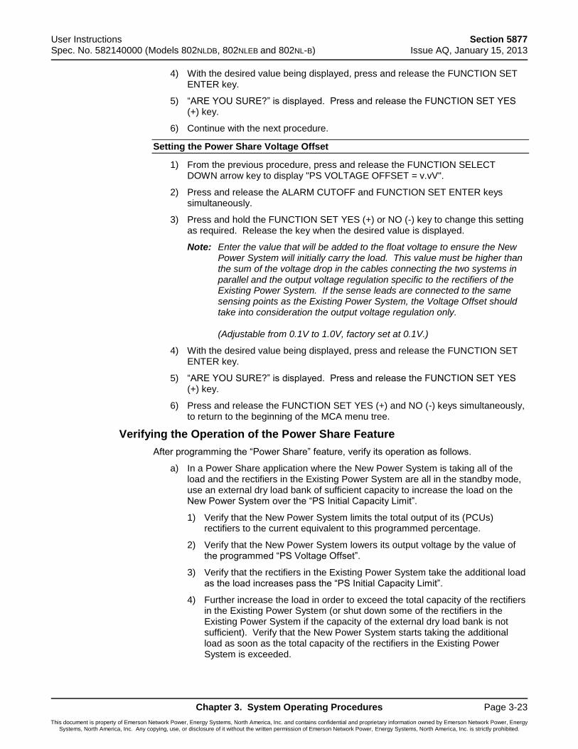
User Instructions Section 5877 Spec. No. 582140000 (Models 802NLDB, 802NLEB and 802NL-B) Issue AQ, January 15, 2013
Chapter 3. System Operating Procedures Page 3-23
This document is property of Emerson Network Power, Energy Systems, North America, Inc. and contains confidential and proprietary information owned by Emerson Network Power, Energy Systems, North America, Inc. Any copying, use, or disclosure of it without the written permission of Emerson Network Power, Energy Systems, North America, Inc. is strictly prohibited.
4) With the desired value being displayed, press and release the FUNCTION SET ENTER key.
5) “ARE YOU SURE?” is displayed. Press and release the FUNCTION SET YES (+) key.
6) Continue with the next procedure.
Setting the Power Share Voltage Offset
1) From the previous procedure, press and release the FUNCTION SELECT DOWN arrow key to display "PS VOLTAGE OFFSET = v.vV".
2) Press and release the ALARM CUTOFF and FUNCTION SET ENTER keys simultaneously.
3) Press and hold the FUNCTION SET YES (+) or NO (-) key to change this setting as required. Release the key when the desired value is displayed.
Note: Enter the value that will be added to the float voltage to ensure the New Power System will initially carry the load. This value must be higher than the sum of the voltage drop in the cables connecting the two systems in parallel and the output voltage regulation specific to the rectifiers of the Existing Power System. If the sense leads are connected to the same sensing points as the Existing Power System, the Voltage Offset should take into consideration the output voltage regulation only. (Adjustable from 0.1V to 1.0V, factory set at 0.1V.)
4) With the desired value being displayed, press and release the FUNCTION SET ENTER key.
5) “ARE YOU SURE?” is displayed. Press and release the FUNCTION SET YES (+) key.
6) Press and release the FUNCTION SET YES (+) and NO (-) keys simultaneously, to return to the beginning of the MCA menu tree.
Verifying the Operation of the Power Share Feature
After programming the “Power Share” feature, verify its operation as follows.
a) In a Power Share application where the New Power System is taking all of the load and the rectifiers in the Existing Power System are all in the standby mode, use an external dry load bank of sufficient capacity to increase the load on the New Power System over the “PS Initial Capacity Limit”.
1) Verify that the New Power System limits the total output of its (PCUs) rectifiers to the current equivalent to this programmed percentage.
2) Verify that the New Power System lowers its output voltage by the value of the programmed “PS Voltage Offset”.
3) Verify that the rectifiers in the Existing Power System take the additional load as the load increases pass the “PS Initial Capacity Limit”.
4) Further increase the load in order to exceed the total capacity of the rectifiers in the Existing Power System (or shut down some of the rectifiers in the Existing Power System if the capacity of the external dry load bank is not sufficient). Verify that the New Power System starts taking the additional load as soon as the total capacity of the rectifiers in the Existing Power System is exceeded.
Section 5877 User Instructions Issue AQ, January 15, 2013 Spec. No. 582140000 (Models 802NLDB, 802NLEB and 802NL-B)
Page 3-24 Chapter 3. System Operating Procedures
This document is property of Emerson Network Power, Energy Systems, North America, Inc. and contains confidential and proprietary information owned by Emerson Network Power, Energy Systems, North America, Inc. Any copying, use, or disclosure of it without the written permission of Emerson Network Power, Energy Systems, North America, Inc. is strictly prohibited.
b) In a Power Share application where the New Power System is taking only part of the load (operating continuously at the current level equivalent to the programmed “PS Initial Capacity Limit” percentage) and the rectifiers in the Existing Power System are taking the rest of the load, use an external dry load bank of sufficient capacity to increase the load in order to exceed the total capacity of the rectifiers in the Existing Power System (or shut down some of the rectifiers in the Existing Power System if the capacity of the external dry load bank is not sufficient).
1) Verify that the New Power System starts taking the additional load as soon as the total capacity of the rectifiers in the Existing Power System is exceeded.
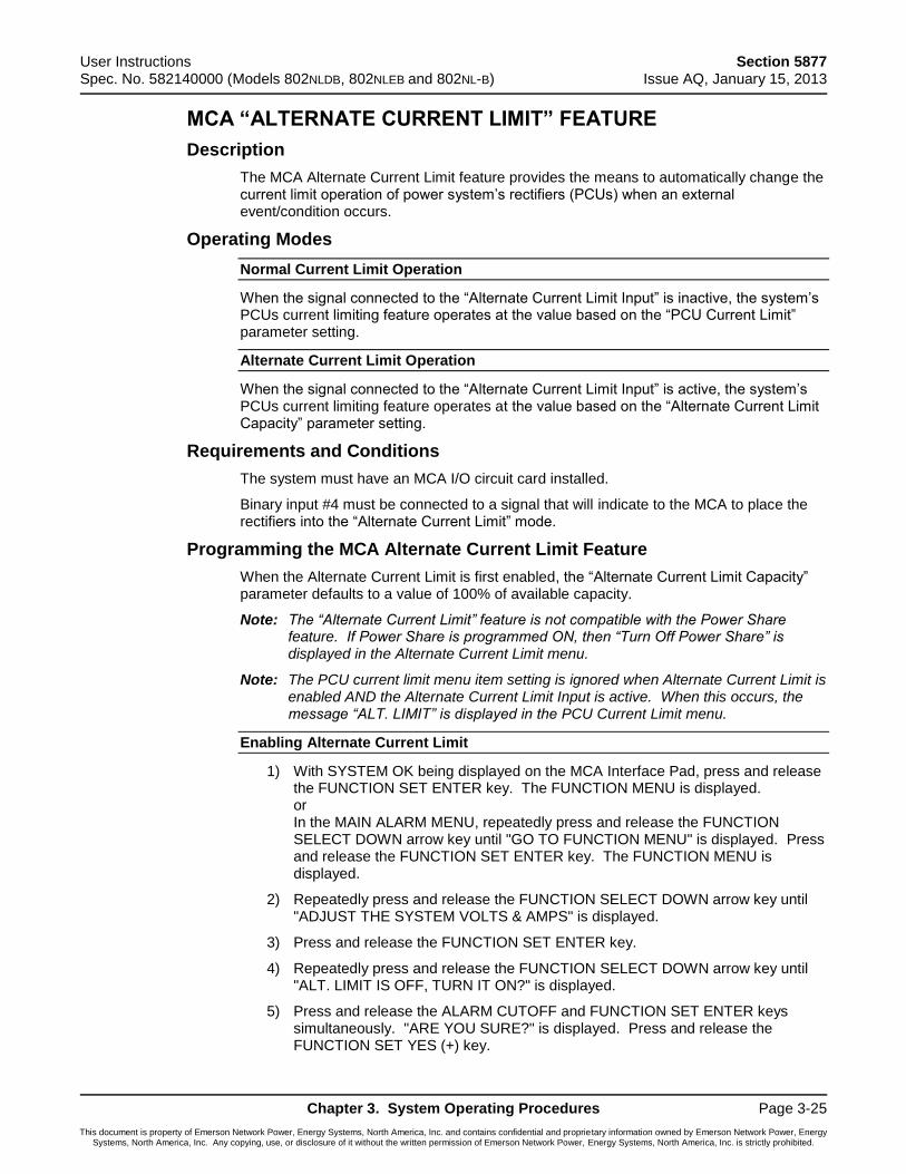
User Instructions Section 5877 Spec. No. 582140000 (Models 802NLDB, 802NLEB and 802NL-B) Issue AQ, January 15, 2013
Chapter 3. System Operating Procedures Page 3-25
This document is property of Emerson Network Power, Energy Systems, North America, Inc. and contains confidential and proprietary information owned by Emerson Network Power, Energy Systems, North America, Inc. Any copying, use, or disclosure of it without the written permission of Emerson Network Power, Energy Systems, North America, Inc. is strictly prohibited.
MCA “ALTERNATE CURRENT LIMIT” FEATURE
Description
The MCA Alternate Current Limit feature provides the means to automatically change the current limit operation of power system’s rectifiers (PCUs) when an external event/condition occurs.
Operating Modes
Normal Current Limit Operation
When the signal connected to the “Alternate Current Limit Input” is inactive, the system’s PCUs current limiting feature operates at the value based on the “PCU Current Limit” parameter setting.
Alternate Current Limit Operation
When the signal connected to the “Alternate Current Limit Input” is active, the system’s PCUs current limiting feature operates at the value based on the “Alternate Current Limit Capacity” parameter setting.
Requirements and Conditions
The system must have an MCA I/O circuit card installed.
Binary input #4 must be connected to a signal that will indicate to the MCA to place the rectifiers into the “Alternate Current Limit” mode.
Programming the MCA Alternate Current Limit Feature
When the Alternate Current Limit is first enabled, the “Alternate Current Limit Capacity” parameter defaults to a value of 100% of available capacity.
Note: The “Alternate Current Limit” feature is not compatible with the Power Share feature. If Power Share is programmed ON, then “Turn Off Power Share” is displayed in the Alternate Current Limit menu.
Note: The PCU current limit menu item setting is ignored when Alternate Current Limit is enabled AND the Alternate Current Limit Input is active. When this occurs, the message “ALT. LIMIT” is displayed in the PCU Current Limit menu.
Enabling Alternate Current Limit
1) With SYSTEM OK being displayed on the MCA Interface Pad, press and release the FUNCTION SET ENTER key. The FUNCTION MENU is displayed. or In the MAIN ALARM MENU, repeatedly press and release the FUNCTION SELECT DOWN arrow key until "GO TO FUNCTION MENU" is displayed. Press and release the FUNCTION SET ENTER key. The FUNCTION MENU is displayed.
2) Repeatedly press and release the FUNCTION SELECT DOWN arrow key until "ADJUST THE SYSTEM VOLTS & AMPS" is displayed.
3) Press and release the FUNCTION SET ENTER key.
4) Repeatedly press and release the FUNCTION SELECT DOWN arrow key until "ALT. LIMIT IS OFF, TURN IT ON?" is displayed.
5) Press and release the ALARM CUTOFF and FUNCTION SET ENTER keys simultaneously. "ARE YOU SURE?" is displayed. Press and release the FUNCTION SET YES (+) key.
Section 5877 User Instructions Issue AQ, January 15, 2013 Spec. No. 582140000 (Models 802NLDB, 802NLEB and 802NL-B)
Page 3-26 Chapter 3. System Operating Procedures
This document is property of Emerson Network Power, Energy Systems, North America, Inc. and contains confidential and proprietary information owned by Emerson Network Power, Energy Systems, North America, Inc. Any copying, use, or disclosure of it without the written permission of Emerson Network Power, Energy Systems, North America, Inc. is strictly prohibited.
6) Continue with the next procedure.
Setting the Alternate Current Limit Initial Capacity Limit
1) From the previous procedure, press and release the FUNCTION SELECT DOWN arrow key to display "ALTERNATE CURRENT LIMIT = ##%".
2) Press and release the ALARM CUTOFF and FUNCTION SET ENTER keys simultaneously.
3) Press and hold the FUNCTION SET YES (+) or NO (-) key to change this setting as required. Release the key when the desired value is displayed.
Note: Enter the percentage value of the total PCU output capacity at which the system will current limit when the “Alternate Current Limit Input” becomes active. (Adjustable from 10% to 110%, factory set at 100%.)
4) With the desired value being displayed, press and release the FUNCTION SET ENTER key.
5) “ARE YOU SURE?” is displayed. Press and release the FUNCTION SET YES (+) key.
6) Press and release the FUNCTION SET YES (+) and NO (-) keys simultaneously, to return to the beginning of the MCA menu tree.
User Instructions Section 5877 Spec. No. 582140000 (Models 802NLDB, 802NLEB and 802NL-B) Issue AQ, January 15, 2013
Chapter 4. MCA System Adjustments Page 4-1
This document is property of Emerson Network Power, Energy Systems, North America, Inc. and contains confidential and proprietary information owned by Emerson Network Power, Energy Systems, North America, Inc. Any copying, use, or disclosure of it without the written permission of Emerson Network Power, Energy Systems, North America, Inc. is strictly prohibited.
CHAPTER 4 MCA SYSTEM ADJUSTMENTS
TABLE OF CONTENTS
Adjustment Location and Identification ............................................................................ 4-2
Adjusting Float Output Voltage ........................................................................................ 4-3
Adjusting Test/Equalize Output Voltage .......................................................................... 4-4
Adjusting High Voltage Shutdown ................................................................................... 4-5
Adjusting Rectifier Current Limit ...................................................................................... 4-6
Adjusting System High Voltage Alarm 1 .......................................................................... 4-7
Adjusting System High Voltage Alarm 2 .......................................................................... 4-8
Adjusting System Battery On Discharge Alarm ............................................................... 4-9
Adjusting System Very Low Voltage Alarm ................................................................... 4-10
Adjusting Total Distribution Load Alarm ........................................................................ 4-11
Adjusting Distribution Group A Load Alarm ................................................................... 4-12
Adjusting Distribution Group B Load Alarm ................................................................... 4-13
Adjusting Battery Ambient High Temperature #1 Alarm (if Battery Charge Digital Temperature Compensation Probe is installed) ............................................................ 4-14
Adjusting Battery Ambient High Temperature #2 Alarm (if Battery Charge Digital Temperature Compensation Probe is installed) ............................................................ 4-15
Adjusting Battery Ambient Low Temperature #1 Alarm (if Battery Charge Digital Temperature Compensation Probe is installed) ............................................................ 4-16
Adjusting Battery Ambient Low Temperature #2 Alarm (if Battery Charge Digital Temperature Compensation Probe is installed) ............................................................ 4-17
Configuring Battery Charge Digital Temperature Compensation Slope ....................... 4-18
Configuring Battery Charge Digital Temperature Compensation Maximum Voltage........................................................................................................................... 4-19
Configuring Battery Charge Digital Temperature Compensation Minimum Voltage ..... 4-20
Configuring Degree Units Displayed ( F or C) ............................................................. 4-21
Configuring the System Date and Time ........................................................................ 4-22
Configuring MCA I/O Circuit Card Analog Input(s) ........................................................ 4-23
Configuring MCA I/O Circuit Card Analog Output(s) ..................................................... 4-25
Configuring MCA I/O Circuit Card Binary Input(s) ......................................................... 4-26
MCA Audible Alarm Cutoff Reset Time Period.............................................................. 4-27
MCA Rectifier Sequencing Feature ............................................................................... 4-27
Manually Initiated Timed Test/Equalize Feature ........................................................... 4-27
Automatic Test/Equalize Feature .................................................................................. 4-27
MCA Power Share Feature ........................................................................................... 4-27
Alarm Relay Test Feature .............................................................................................. 4-27
MCA “Alternate Current Limit” Feature .......................................................................... 4-27
Section 5877 User Instructions Issue AQ, January 15, 2013 Spec. No. 582140000 (Models 802NLDB, 802NLEB and 802NL-B)
Page 4-2 Chapter 4. MCA System Adjustments
This document is property of Emerson Network Power, Energy Systems, North America, Inc. and contains confidential and proprietary information owned by Emerson Network Power, Energy Systems, North America, Inc. Any copying, use, or disclosure of it without the written permission of Emerson Network Power, Energy Systems, North America, Inc. is strictly prohibited.
ADJUSTMENT LOCATION AND IDENTIFICATION
All system alarm and control circuits intended for customer adjustment are accessible via the MCA Control Panel. Unless otherwise stated, these circuits have been factory set to the values listed in the System Application Guide. If readjustment is necessary, perform the appropriate adjustment procedure detailed below.
These adjustments can also be done remotely via the LMS (if furnished). To adjust the system via the optional LMS system, refer to the LMS User Instructions (Section 5847). Section 5847 can be accessed via the CD (Electronic Documentation Package) furnished with your system.
Refer to the illustrations in Chapter 1. System Overview for local adjustment controls locations.
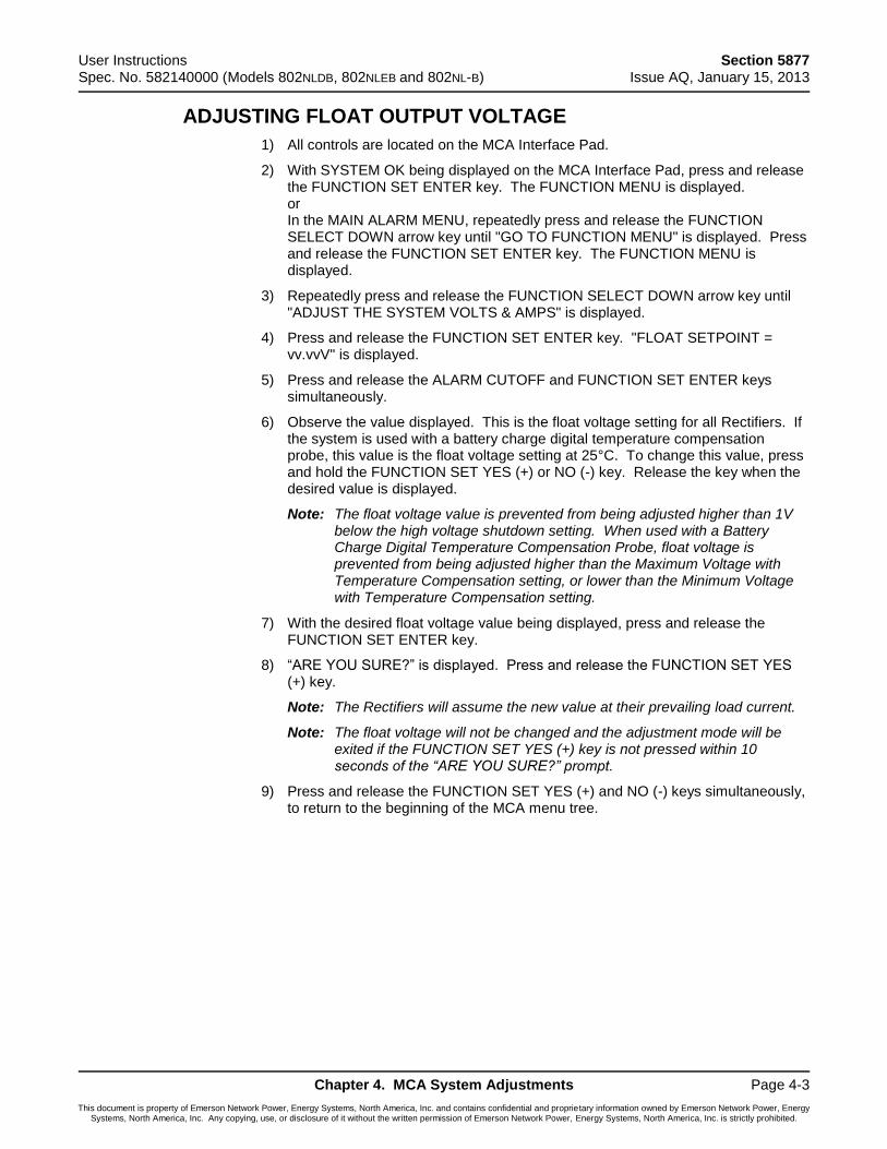
User Instructions Section 5877 Spec. No. 582140000 (Models 802NLDB, 802NLEB and 802NL-B) Issue AQ, January 15, 2013
Chapter 4. MCA System Adjustments Page 4-3
This document is property of Emerson Network Power, Energy Systems, North America, Inc. and contains confidential and proprietary information owned by Emerson Network Power, Energy Systems, North America, Inc. Any copying, use, or disclosure of it without the written permission of Emerson Network Power, Energy Systems, North America, Inc. is strictly prohibited.
ADJUSTING FLOAT OUTPUT VOLTAGE
1) All controls are located on the MCA Interface Pad.
2) With SYSTEM OK being displayed on the MCA Interface Pad, press and release the FUNCTION SET ENTER key. The FUNCTION MENU is displayed. or In the MAIN ALARM MENU, repeatedly press and release the FUNCTION SELECT DOWN arrow key until "GO TO FUNCTION MENU" is displayed. Press and release the FUNCTION SET ENTER key. The FUNCTION MENU is displayed.
3) Repeatedly press and release the FUNCTION SELECT DOWN arrow key until "ADJUST THE SYSTEM VOLTS & AMPS" is displayed.
4) Press and release the FUNCTION SET ENTER key. "FLOAT SETPOINT = vv.vvV" is displayed.
5) Press and release the ALARM CUTOFF and FUNCTION SET ENTER keys simultaneously.
6) Observe the value displayed. This is the float voltage setting for all Rectifiers. If the system is used with a battery charge digital temperature compensation probe, this value is the float voltage setting at 25°C. To change this value, press and hold the FUNCTION SET YES (+) or NO (-) key. Release the key when the desired value is displayed.
Note: The float voltage value is prevented from being adjusted higher than 1V below the high voltage shutdown setting. When used with a Battery Charge Digital Temperature Compensation Probe, float voltage is prevented from being adjusted higher than the Maximum Voltage with Temperature Compensation setting, or lower than the Minimum Voltage with Temperature Compensation setting.
7) With the desired float voltage value being displayed, press and release the FUNCTION SET ENTER key.
8) “ARE YOU SURE?” is displayed. Press and release the FUNCTION SET YES (+) key.
Note: The Rectifiers will assume the new value at their prevailing load current.
Note: The float voltage will not be changed and the adjustment mode will be exited if the FUNCTION SET YES (+) key is not pressed within 10 seconds of the “ARE YOU SURE?” prompt.
9) Press and release the FUNCTION SET YES (+) and NO (-) keys simultaneously, to return to the beginning of the MCA menu tree.
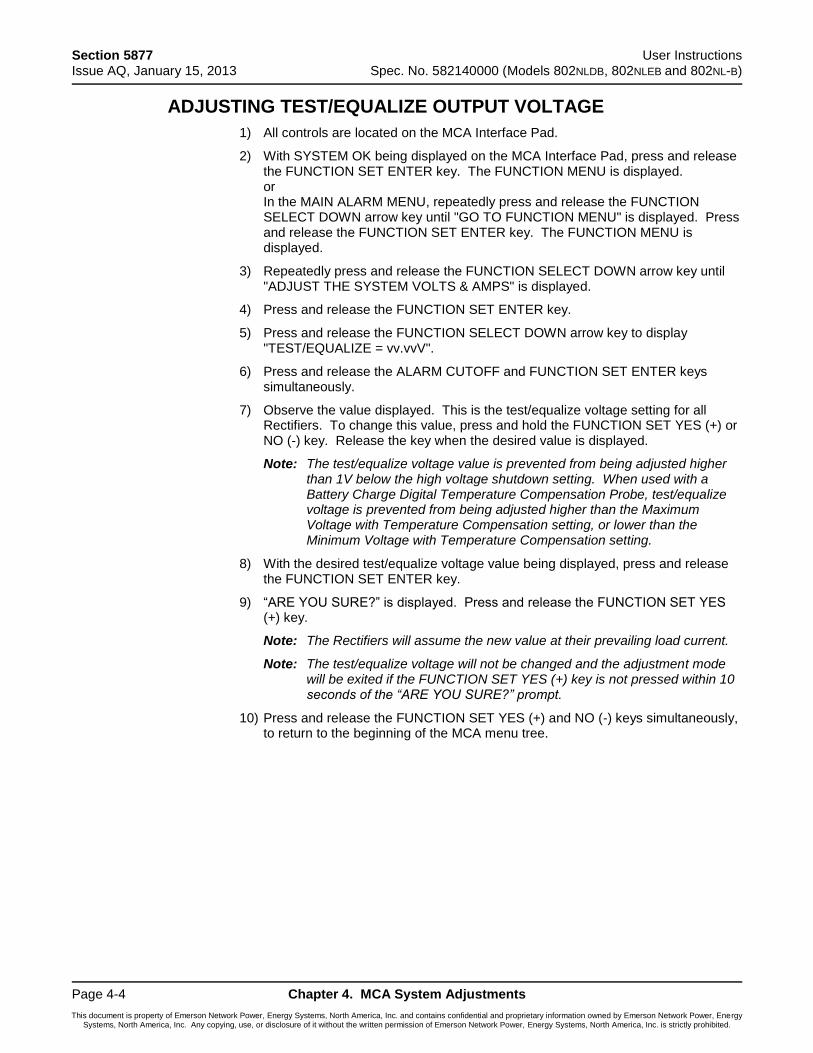
Section 5877 User Instructions Issue AQ, January 15, 2013 Spec. No. 582140000 (Models 802NLDB, 802NLEB and 802NL-B)
Page 4-4 Chapter 4. MCA System Adjustments
This document is property of Emerson Network Power, Energy Systems, North America, Inc. and contains confidential and proprietary information owned by Emerson Network Power, Energy Systems, North America, Inc. Any copying, use, or disclosure of it without the written permission of Emerson Network Power, Energy Systems, North America, Inc. is strictly prohibited.
ADJUSTING TEST/EQUALIZE OUTPUT VOLTAGE
1) All controls are located on the MCA Interface Pad.
2) With SYSTEM OK being displayed on the MCA Interface Pad, press and release the FUNCTION SET ENTER key. The FUNCTION MENU is displayed. or In the MAIN ALARM MENU, repeatedly press and release the FUNCTION SELECT DOWN arrow key until "GO TO FUNCTION MENU" is displayed. Press and release the FUNCTION SET ENTER key. The FUNCTION MENU is displayed.
3) Repeatedly press and release the FUNCTION SELECT DOWN arrow key until "ADJUST THE SYSTEM VOLTS & AMPS" is displayed.
4) Press and release the FUNCTION SET ENTER key.
5) Press and release the FUNCTION SELECT DOWN arrow key to display "TEST/EQUALIZE = vv.vvV".
6) Press and release the ALARM CUTOFF and FUNCTION SET ENTER keys simultaneously.
7) Observe the value displayed. This is the test/equalize voltage setting for all Rectifiers. To change this value, press and hold the FUNCTION SET YES (+) or NO (-) key. Release the key when the desired value is displayed.
Note: The test/equalize voltage value is prevented from being adjusted higher than 1V below the high voltage shutdown setting. When used with a Battery Charge Digital Temperature Compensation Probe, test/equalize voltage is prevented from being adjusted higher than the Maximum Voltage with Temperature Compensation setting, or lower than the Minimum Voltage with Temperature Compensation setting.
8) With the desired test/equalize voltage value being displayed, press and release the FUNCTION SET ENTER key.
9) “ARE YOU SURE?” is displayed. Press and release the FUNCTION SET YES (+) key.
Note: The Rectifiers will assume the new value at their prevailing load current.
Note: The test/equalize voltage will not be changed and the adjustment mode will be exited if the FUNCTION SET YES (+) key is not pressed within 10 seconds of the “ARE YOU SURE?” prompt.
10) Press and release the FUNCTION SET YES (+) and NO (-) keys simultaneously, to return to the beginning of the MCA menu tree.
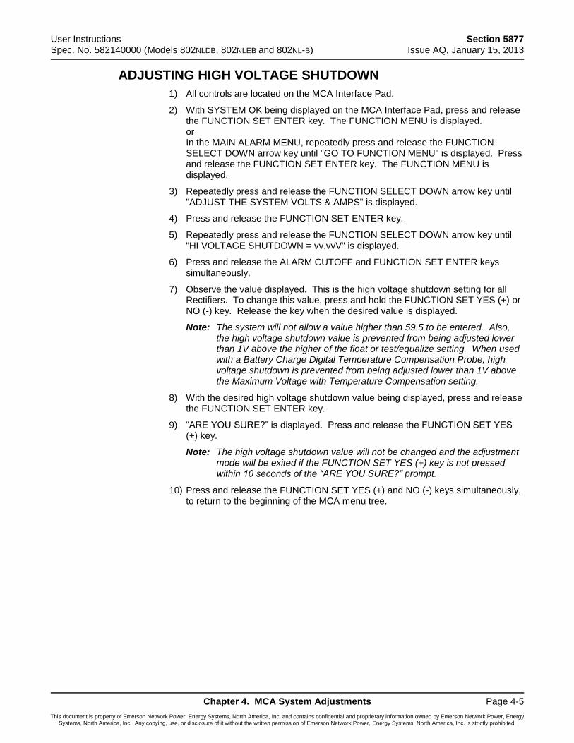
User Instructions Section 5877 Spec. No. 582140000 (Models 802NLDB, 802NLEB and 802NL-B) Issue AQ, January 15, 2013
Chapter 4. MCA System Adjustments Page 4-5
This document is property of Emerson Network Power, Energy Systems, North America, Inc. and contains confidential and proprietary information owned by Emerson Network Power, Energy Systems, North America, Inc. Any copying, use, or disclosure of it without the written permission of Emerson Network Power, Energy Systems, North America, Inc. is strictly prohibited.
ADJUSTING HIGH VOLTAGE SHUTDOWN
1) All controls are located on the MCA Interface Pad.
2) With SYSTEM OK being displayed on the MCA Interface Pad, press and release the FUNCTION SET ENTER key. The FUNCTION MENU is displayed. or In the MAIN ALARM MENU, repeatedly press and release the FUNCTION SELECT DOWN arrow key until "GO TO FUNCTION MENU" is displayed. Press and release the FUNCTION SET ENTER key. The FUNCTION MENU is displayed.
3) Repeatedly press and release the FUNCTION SELECT DOWN arrow key until "ADJUST THE SYSTEM VOLTS & AMPS" is displayed.
4) Press and release the FUNCTION SET ENTER key.
5) Repeatedly press and release the FUNCTION SELECT DOWN arrow key until "HI VOLTAGE SHUTDOWN = vv.vvV" is displayed.
6) Press and release the ALARM CUTOFF and FUNCTION SET ENTER keys simultaneously.
7) Observe the value displayed. This is the high voltage shutdown setting for all Rectifiers. To change this value, press and hold the FUNCTION SET YES (+) or NO (-) key. Release the key when the desired value is displayed.
Note: The system will not allow a value higher than 59.5 to be entered. Also, the high voltage shutdown value is prevented from being adjusted lower than 1V above the higher of the float or test/equalize setting. When used with a Battery Charge Digital Temperature Compensation Probe, high voltage shutdown is prevented from being adjusted lower than 1V above the Maximum Voltage with Temperature Compensation setting.
8) With the desired high voltage shutdown value being displayed, press and release the FUNCTION SET ENTER key.
9) “ARE YOU SURE?” is displayed. Press and release the FUNCTION SET YES (+) key.
Note: The high voltage shutdown value will not be changed and the adjustment mode will be exited if the FUNCTION SET YES (+) key is not pressed within 10 seconds of the “ARE YOU SURE?” prompt.
10) Press and release the FUNCTION SET YES (+) and NO (-) keys simultaneously, to return to the beginning of the MCA menu tree.
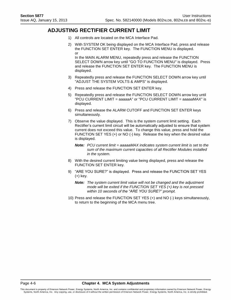
Section 5877 User Instructions Issue AQ, January 15, 2013 Spec. No. 582140000 (Models 802NLDB, 802NLEB and 802NL-B)
Page 4-6 Chapter 4. MCA System Adjustments
This document is property of Emerson Network Power, Energy Systems, North America, Inc. and contains confidential and proprietary information owned by Emerson Network Power, Energy Systems, North America, Inc. Any copying, use, or disclosure of it without the written permission of Emerson Network Power, Energy Systems, North America, Inc. is strictly prohibited.
ADJUSTING RECTIFIER CURRENT LIMIT
1) All controls are located on the MCA Interface Pad.
2) With SYSTEM OK being displayed on the MCA Interface Pad, press and release the FUNCTION SET ENTER key. The FUNCTION MENU is displayed. or In the MAIN ALARM MENU, repeatedly press and release the FUNCTION SELECT DOWN arrow key until "GO TO FUNCTION MENU" is displayed. Press and release the FUNCTION SET ENTER key. The FUNCTION MENU is displayed.
3) Repeatedly press and release the FUNCTION SELECT DOWN arrow key until "ADJUST THE SYSTEM VOLTS & AMPS" is displayed.
4) Press and release the FUNCTION SET ENTER key.
5) Repeatedly press and release the FUNCTION SELECT DOWN arrow key until "PCU CURRENT LIMIT = aaaaaA" or "PCU CURRENT LIMIT = aaaaaMAX" is displayed.
6) Press and release the ALARM CUTOFF and FUNCTION SET ENTER keys simultaneously.
7) Observe the value displayed. This is the system current limit setting. Each Rectifier’s current limit circuit will be automatically adjusted to ensure that system current does not exceed this value. To change this value, press and hold the FUNCTION SET YES (+) or NO (-) key. Release the key when the desired value is displayed.
Note: PCU current limit = aaaaaMAX indicates system current limit is set to the sum of the maximum current capacities of all Rectifier Modules installed in the system.
8) With the desired current limiting value being displayed, press and release the FUNCTION SET ENTER key.
9) “ARE YOU SURE?” is displayed. Press and release the FUNCTION SET YES (+) key.
Note: The system current limit value will not be changed and the adjustment mode will be exited if the FUNCTION SET YES (+) key is not pressed within 10 seconds of the “ARE YOU SURE?” prompt.
10) Press and release the FUNCTION SET YES (+) and NO (-) keys simultaneously, to return to the beginning of the MCA menu tree.
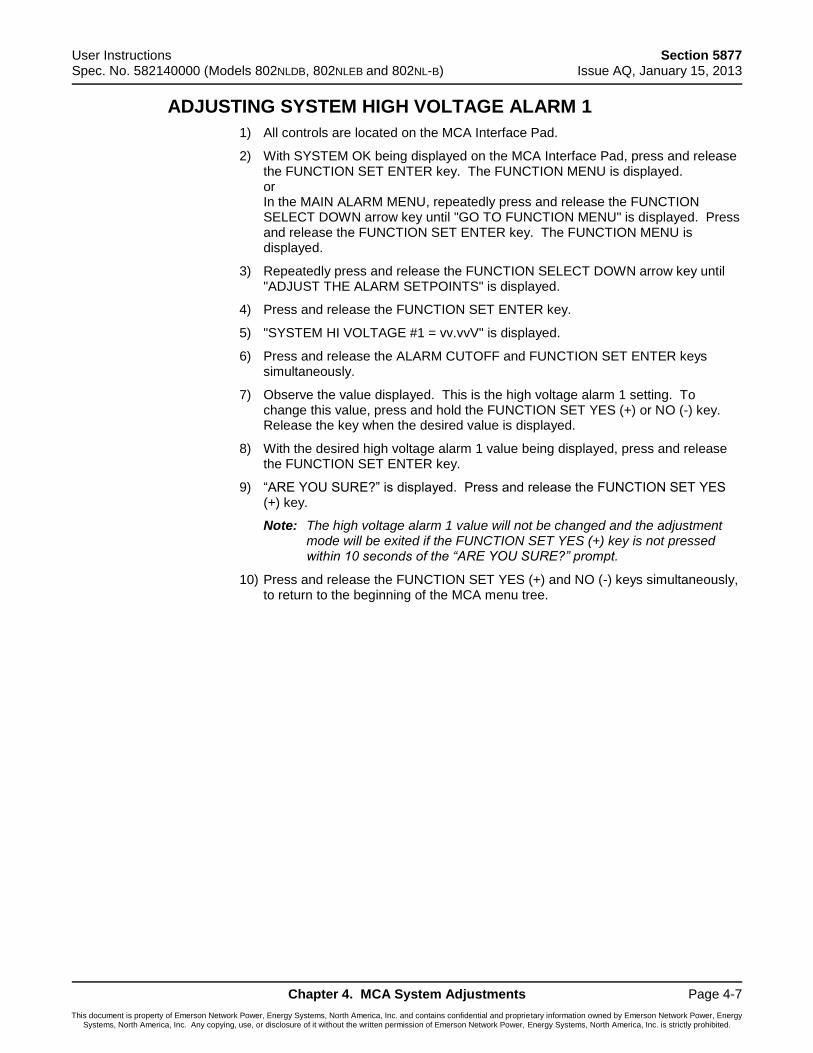
User Instructions Section 5877 Spec. No. 582140000 (Models 802NLDB, 802NLEB and 802NL-B) Issue AQ, January 15, 2013
Chapter 4. MCA System Adjustments Page 4-7
This document is property of Emerson Network Power, Energy Systems, North America, Inc. and contains confidential and proprietary information owned by Emerson Network Power, Energy Systems, North America, Inc. Any copying, use, or disclosure of it without the written permission of Emerson Network Power, Energy Systems, North America, Inc. is strictly prohibited.
ADJUSTING SYSTEM HIGH VOLTAGE ALARM 1
1) All controls are located on the MCA Interface Pad.
2) With SYSTEM OK being displayed on the MCA Interface Pad, press and release the FUNCTION SET ENTER key. The FUNCTION MENU is displayed. or In the MAIN ALARM MENU, repeatedly press and release the FUNCTION SELECT DOWN arrow key until "GO TO FUNCTION MENU" is displayed. Press and release the FUNCTION SET ENTER key. The FUNCTION MENU is displayed.
3) Repeatedly press and release the FUNCTION SELECT DOWN arrow key until "ADJUST THE ALARM SETPOINTS" is displayed.
4) Press and release the FUNCTION SET ENTER key.
5) "SYSTEM HI VOLTAGE #1 = vv.vvV" is displayed.
6) Press and release the ALARM CUTOFF and FUNCTION SET ENTER keys simultaneously.
7) Observe the value displayed. This is the high voltage alarm 1 setting. To change this value, press and hold the FUNCTION SET YES (+) or NO (-) key. Release the key when the desired value is displayed.
8) With the desired high voltage alarm 1 value being displayed, press and release the FUNCTION SET ENTER key.
9) “ARE YOU SURE?” is displayed. Press and release the FUNCTION SET YES (+) key.
Note: The high voltage alarm 1 value will not be changed and the adjustment mode will be exited if the FUNCTION SET YES (+) key is not pressed within 10 seconds of the “ARE YOU SURE?” prompt.
10) Press and release the FUNCTION SET YES (+) and NO (-) keys simultaneously, to return to the beginning of the MCA menu tree.

Section 5877 User Instructions Issue AQ, January 15, 2013 Spec. No. 582140000 (Models 802NLDB, 802NLEB and 802NL-B)
Page 4-8 Chapter 4. MCA System Adjustments
This document is property of Emerson Network Power, Energy Systems, North America, Inc. and contains confidential and proprietary information owned by Emerson Network Power, Energy Systems, North America, Inc. Any copying, use, or disclosure of it without the written permission of Emerson Network Power, Energy Systems, North America, Inc. is strictly prohibited.
ADJUSTING SYSTEM HIGH VOLTAGE ALARM 2
1) All controls are located on the MCA Interface Pad.
2) With SYSTEM OK being displayed on the MCA Interface Pad, press and release the FUNCTION SET ENTER key. The FUNCTION MENU is displayed. or In the MAIN ALARM MENU, repeatedly press and release the FUNCTION SELECT DOWN arrow key until "GO TO FUNCTION MENU" is displayed. Press and release the FUNCTION SET ENTER key. The FUNCTION MENU is displayed.
3) Repeatedly press and release the FUNCTION SELECT DOWN arrow key until "ADJUST THE ALARM SETPOINTS" is displayed.
4) Press and release the FUNCTION SET ENTER key.
5) Press and release the FUNCTION SELECT DOWN arrow key to display "SYSTEM HI VOLTAGE #2 = vv.vvV".
6) Press and release the ALARM CUTOFF and FUNCTION SET ENTER keys simultaneously.
7) Observe the value displayed. This is the high voltage alarm 2 setting. To change this value, press and hold the FUNCTION SET YES (+) or NO (-) key. Release the key when the desired value is displayed.
8) With the desired high voltage alarm 2 value being displayed, press and release the FUNCTION SET ENTER key.
9) “ARE YOU SURE?” is displayed. Press and release the FUNCTION SET YES (+) key.
Note: The high voltage alarm 2 value will not be changed and the adjustment mode will be exited if the FUNCTION SET YES (+) key is not pressed within 10 seconds of the “ARE YOU SURE?” prompt.
10) Press and release the FUNCTION SET YES (+) and NO (-) keys simultaneously, to return to the beginning of the MCA menu tree.

User Instructions Section 5877 Spec. No. 582140000 (Models 802NLDB, 802NLEB and 802NL-B) Issue AQ, January 15, 2013
Chapter 4. MCA System Adjustments Page 4-9
This document is property of Emerson Network Power, Energy Systems, North America, Inc. and contains confidential and proprietary information owned by Emerson Network Power, Energy Systems, North America, Inc. Any copying, use, or disclosure of it without the written permission of Emerson Network Power, Energy Systems, North America, Inc. is strictly prohibited.
ADJUSTING SYSTEM BATTERY ON DISCHARGE ALARM
1) All controls are located on the MCA Interface Pad.
2) With SYSTEM OK being displayed on the MCA Interface Pad, press and release the FUNCTION SET ENTER key. The FUNCTION MENU is displayed. or In the MAIN ALARM MENU, repeatedly press and release the FUNCTION SELECT DOWN arrow key until "GO TO FUNCTION MENU" is displayed. Press and release the FUNCTION SET ENTER key. The FUNCTION MENU is displayed.
3) Repeatedly press and release the FUNCTION SELECT DOWN arrow key until "ADJUST THE ALARM SETPOINTS" is displayed.
4) Press and release the FUNCTION SET ENTER key.
5) Repeatedly press and release the FUNCTION SELECT DOWN arrow key until "BATTERY ON DISCHARGE = vv.vvV" is displayed.
6) Press and release the ALARM CUTOFF and FUNCTION SET ENTER keys simultaneously.
7) Observe the value displayed. This is the battery on discharge alarm setting. To change this value, press and hold the FUNCTION SET YES (+) or NO (-) key. Release the key when the desired value is displayed.
8) With the desired battery on discharge alarm value being displayed, press and release the FUNCTION SET ENTER key.
9) “ARE YOU SURE?” is displayed. Press and release the FUNCTION SET YES (+) key.
Note: The battery on discharge value will not be changed and the adjustment mode will be exited if the FUNCTION SET YES (+) key is not pressed within 10 seconds of the “ARE YOU SURE?” prompt.
10) Press and release the FUNCTION SET YES (+) and NO (-) keys simultaneously, to return to the beginning of the MCA menu tree.

Section 5877 User Instructions Issue AQ, January 15, 2013 Spec. No. 582140000 (Models 802NLDB, 802NLEB and 802NL-B)
Page 4-10 Chapter 4. MCA System Adjustments
This document is property of Emerson Network Power, Energy Systems, North America, Inc. and contains confidential and proprietary information owned by Emerson Network Power, Energy Systems, North America, Inc. Any copying, use, or disclosure of it without the written permission of Emerson Network Power, Energy Systems, North America, Inc. is strictly prohibited.
ADJUSTING SYSTEM VERY LOW VOLTAGE ALARM
1) All controls are located on the MCA Interface Pad.
2) With SYSTEM OK being displayed on the MCA Interface Pad, press and release the FUNCTION SET ENTER key. The FUNCTION MENU is displayed. or In the MAIN ALARM MENU, repeatedly press and release the FUNCTION SELECT DOWN arrow key until "GO TO FUNCTION MENU" is displayed. Press and release the FUNCTION SET ENTER key. The FUNCTION MENU is displayed.
3) Repeatedly press and release the FUNCTION SELECT DOWN arrow key until "ADJUST THE ALARM SETPOINTS" is displayed.
4) Press and release the FUNCTION SET ENTER key.
5) Repeatedly press and release the FUNCTION SELECT DOWN arrow key until "VERY LOW VOLTAGE = vv.vvV" is displayed.
6) Press and release the ALARM CUTOFF and FUNCTION SET ENTER keys simultaneously.
7) Observe the value displayed. This is the very low voltage alarm setting. To change this value, press and hold the FUNCTION SET YES (+) or NO (-) key. Release the key when the desired value is displayed.
8) With the desired very low voltage alarm value being displayed, press and release the FUNCTION SET ENTER key.
9) “ARE YOU SURE?” is displayed. Press and release the FUNCTION SET YES (+) key.
Note: The very low voltage alarm value will not be changed and the adjustment mode will be exited if the FUNCTION SET YES (+) key is not pressed within 10 seconds of the “ARE YOU SURE?” prompt.
10) Press and release the FUNCTION SET YES (+) and NO (-) keys simultaneously, to return to the beginning of the MCA menu tree.
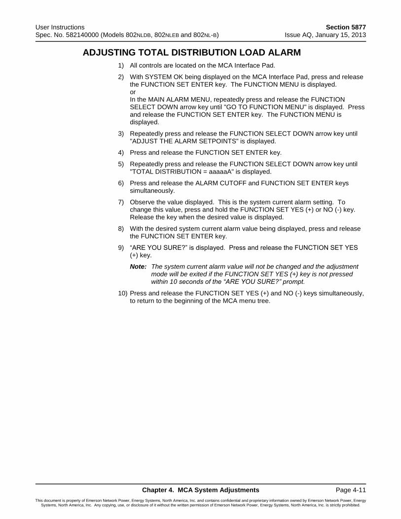
User Instructions Section 5877 Spec. No. 582140000 (Models 802NLDB, 802NLEB and 802NL-B) Issue AQ, January 15, 2013
Chapter 4. MCA System Adjustments Page 4-11
This document is property of Emerson Network Power, Energy Systems, North America, Inc. and contains confidential and proprietary information owned by Emerson Network Power, Energy Systems, North America, Inc. Any copying, use, or disclosure of it without the written permission of Emerson Network Power, Energy Systems, North America, Inc. is strictly prohibited.
ADJUSTING TOTAL DISTRIBUTION LOAD ALARM
1) All controls are located on the MCA Interface Pad.
2) With SYSTEM OK being displayed on the MCA Interface Pad, press and release the FUNCTION SET ENTER key. The FUNCTION MENU is displayed. or In the MAIN ALARM MENU, repeatedly press and release the FUNCTION SELECT DOWN arrow key until "GO TO FUNCTION MENU" is displayed. Press and release the FUNCTION SET ENTER key. The FUNCTION MENU is displayed.
3) Repeatedly press and release the FUNCTION SELECT DOWN arrow key until "ADJUST THE ALARM SETPOINTS" is displayed.
4) Press and release the FUNCTION SET ENTER key.
5) Repeatedly press and release the FUNCTION SELECT DOWN arrow key until "TOTAL DISTRIBUTION = aaaaaA" is displayed.
6) Press and release the ALARM CUTOFF and FUNCTION SET ENTER keys simultaneously.
7) Observe the value displayed. This is the system current alarm setting. To change this value, press and hold the FUNCTION SET YES (+) or NO (-) key. Release the key when the desired value is displayed.
8) With the desired system current alarm value being displayed, press and release the FUNCTION SET ENTER key.
9) “ARE YOU SURE?” is displayed. Press and release the FUNCTION SET YES (+) key.
Note: The system current alarm value will not be changed and the adjustment mode will be exited if the FUNCTION SET YES (+) key is not pressed within 10 seconds of the “ARE YOU SURE?” prompt.
10) Press and release the FUNCTION SET YES (+) and NO (-) keys simultaneously, to return to the beginning of the MCA menu tree.
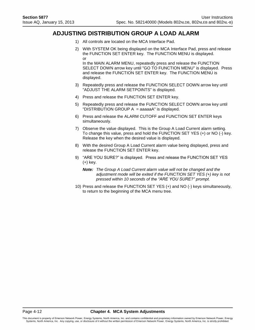
Section 5877 User Instructions Issue AQ, January 15, 2013 Spec. No. 582140000 (Models 802NLDB, 802NLEB and 802NL-B)
Page 4-12 Chapter 4. MCA System Adjustments
This document is property of Emerson Network Power, Energy Systems, North America, Inc. and contains confidential and proprietary information owned by Emerson Network Power, Energy Systems, North America, Inc. Any copying, use, or disclosure of it without the written permission of Emerson Network Power, Energy Systems, North America, Inc. is strictly prohibited.
ADJUSTING DISTRIBUTION GROUP A LOAD ALARM
1) All controls are located on the MCA Interface Pad.
2) With SYSTEM OK being displayed on the MCA Interface Pad, press and release the FUNCTION SET ENTER key. The FUNCTION MENU is displayed. or In the MAIN ALARM MENU, repeatedly press and release the FUNCTION SELECT DOWN arrow key until "GO TO FUNCTION MENU" is displayed. Press and release the FUNCTION SET ENTER key. The FUNCTION MENU is displayed.
3) Repeatedly press and release the FUNCTION SELECT DOWN arrow key until "ADJUST THE ALARM SETPOINTS" is displayed.
4) Press and release the FUNCTION SET ENTER key.
5) Repeatedly press and release the FUNCTION SELECT DOWN arrow key until "DISTRIBUTION GROUP A = aaaaaA" is displayed.
6) Press and release the ALARM CUTOFF and FUNCTION SET ENTER keys simultaneously.
7) Observe the value displayed. This is the Group A Load Current alarm setting. To change this value, press and hold the FUNCTION SET YES (+) or NO (-) key. Release the key when the desired value is displayed.
8) With the desired Group A Load Current alarm value being displayed, press and release the FUNCTION SET ENTER key.
9) “ARE YOU SURE?” is displayed. Press and release the FUNCTION SET YES (+) key.
Note: The Group A Load Current alarm value will not be changed and the adjustment mode will be exited if the FUNCTION SET YES (+) key is not pressed within 10 seconds of the “ARE YOU SURE?” prompt.
10) Press and release the FUNCTION SET YES (+) and NO (-) keys simultaneously, to return to the beginning of the MCA menu tree.
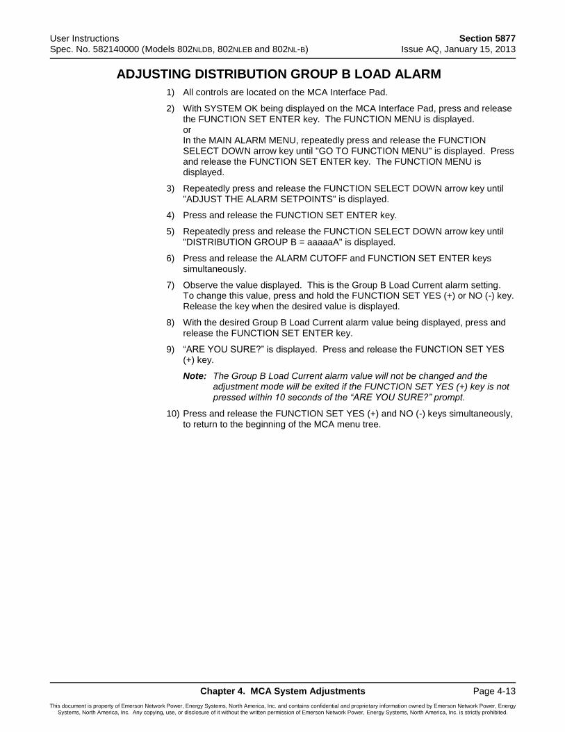
User Instructions Section 5877 Spec. No. 582140000 (Models 802NLDB, 802NLEB and 802NL-B) Issue AQ, January 15, 2013
Chapter 4. MCA System Adjustments Page 4-13
This document is property of Emerson Network Power, Energy Systems, North America, Inc. and contains confidential and proprietary information owned by Emerson Network Power, Energy Systems, North America, Inc. Any copying, use, or disclosure of it without the written permission of Emerson Network Power, Energy Systems, North America, Inc. is strictly prohibited.
ADJUSTING DISTRIBUTION GROUP B LOAD ALARM
1) All controls are located on the MCA Interface Pad.
2) With SYSTEM OK being displayed on the MCA Interface Pad, press and release the FUNCTION SET ENTER key. The FUNCTION MENU is displayed. or In the MAIN ALARM MENU, repeatedly press and release the FUNCTION SELECT DOWN arrow key until "GO TO FUNCTION MENU" is displayed. Press and release the FUNCTION SET ENTER key. The FUNCTION MENU is displayed.
3) Repeatedly press and release the FUNCTION SELECT DOWN arrow key until "ADJUST THE ALARM SETPOINTS" is displayed.
4) Press and release the FUNCTION SET ENTER key.
5) Repeatedly press and release the FUNCTION SELECT DOWN arrow key until "DISTRIBUTION GROUP B = aaaaaA" is displayed.
6) Press and release the ALARM CUTOFF and FUNCTION SET ENTER keys simultaneously.
7) Observe the value displayed. This is the Group B Load Current alarm setting. To change this value, press and hold the FUNCTION SET YES (+) or NO (-) key. Release the key when the desired value is displayed.
8) With the desired Group B Load Current alarm value being displayed, press and release the FUNCTION SET ENTER key.
9) “ARE YOU SURE?” is displayed. Press and release the FUNCTION SET YES (+) key.
Note: The Group B Load Current alarm value will not be changed and the adjustment mode will be exited if the FUNCTION SET YES (+) key is not pressed within 10 seconds of the “ARE YOU SURE?” prompt.
10) Press and release the FUNCTION SET YES (+) and NO (-) keys simultaneously, to return to the beginning of the MCA menu tree.

Section 5877 User Instructions Issue AQ, January 15, 2013 Spec. No. 582140000 (Models 802NLDB, 802NLEB and 802NL-B)
Page 4-14 Chapter 4. MCA System Adjustments
This document is property of Emerson Network Power, Energy Systems, North America, Inc. and contains confidential and proprietary information owned by Emerson Network Power, Energy Systems, North America, Inc. Any copying, use, or disclosure of it without the written permission of Emerson Network Power, Energy Systems, North America, Inc. is strictly prohibited.
ADJUSTING BATTERY AMBIENT HIGH TEMPERATURE #1 ALARM (IF BATTERY CHARGE DIGITAL TEMPERATURE COMPENSATION PROBE IS INSTALLED)
1) All controls are located on the MCA Interface Pad.
2) With SYSTEM OK being displayed on the MCA Interface Pad, press and release the FUNCTION SET ENTER key. The FUNCTION MENU is displayed. or In the MAIN ALARM MENU, repeatedly press and release the FUNCTION SELECT DOWN arrow key until "GO TO FUNCTION MENU" is displayed. Press and release the FUNCTION SET ENTER key. The FUNCTION MENU is displayed.
3) Repeatedly press and release the FUNCTION SELECT DOWN arrow key until "ADJUST THE ALARM SETPOINTS" is displayed.
4) Press and release the FUNCTION SET ENTER key.
5) Repeatedly press and release the FUNCTION SELECT DOWN arrow key until
"NO HIGH TEMPERATURE #1 ALARM” or “HIGH TEMPERATURE #1 = ttt C/F" is displayed.
6) Press and release the ALARM CUTOFF and FUNCTION SET ENTER keys simultaneously.
7) Observe the value displayed. This is the high temperature #1 alarm setting. To change this value, press and hold the FUNCTION SET YES (+) or NO (-) key. Release the key when the desired value is displayed.
8) With the desired high temperature #1 alarm value being displayed, press and release the FUNCTION SET ENTER key.
9) “ARE YOU SURE?” is displayed. Press and release the FUNCTION SET YES (+) key.
Note: The high temperature #1 alarm value will not be changed and the adjustment mode will be exited if the FUNCTION SET YES (+) key is not pressed within 10 seconds of the “ARE YOU SURE?” prompt.
10) Press and release the FUNCTION SET YES (+) and NO (-) keys simultaneously, to return to the beginning of the MCA menu tree.
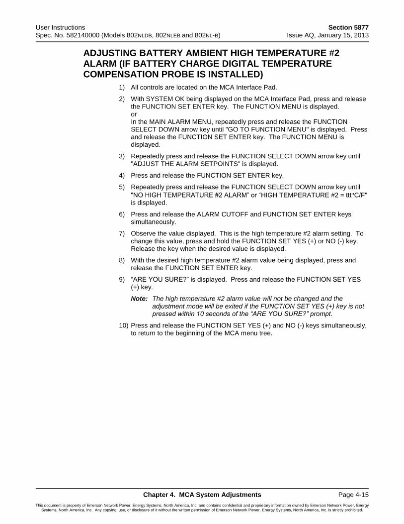
User Instructions Section 5877 Spec. No. 582140000 (Models 802NLDB, 802NLEB and 802NL-B) Issue AQ, January 15, 2013
Chapter 4. MCA System Adjustments Page 4-15
This document is property of Emerson Network Power, Energy Systems, North America, Inc. and contains confidential and proprietary information owned by Emerson Network Power, Energy Systems, North America, Inc. Any copying, use, or disclosure of it without the written permission of Emerson Network Power, Energy Systems, North America, Inc. is strictly prohibited.
ADJUSTING BATTERY AMBIENT HIGH TEMPERATURE #2 ALARM (IF BATTERY CHARGE DIGITAL TEMPERATURE COMPENSATION PROBE IS INSTALLED)
1) All controls are located on the MCA Interface Pad.
2) With SYSTEM OK being displayed on the MCA Interface Pad, press and release the FUNCTION SET ENTER key. The FUNCTION MENU is displayed. or In the MAIN ALARM MENU, repeatedly press and release the FUNCTION SELECT DOWN arrow key until "GO TO FUNCTION MENU" is displayed. Press and release the FUNCTION SET ENTER key. The FUNCTION MENU is displayed.
3) Repeatedly press and release the FUNCTION SELECT DOWN arrow key until "ADJUST THE ALARM SETPOINTS" is displayed.
4) Press and release the FUNCTION SET ENTER key.
5) Repeatedly press and release the FUNCTION SELECT DOWN arrow key until
"NO HIGH TEMPERATURE #2 ALARM” or “HIGH TEMPERATURE #2 = ttt C/F" is displayed.
6) Press and release the ALARM CUTOFF and FUNCTION SET ENTER keys simultaneously.
7) Observe the value displayed. This is the high temperature #2 alarm setting. To change this value, press and hold the FUNCTION SET YES (+) or NO (-) key. Release the key when the desired value is displayed.
8) With the desired high temperature #2 alarm value being displayed, press and release the FUNCTION SET ENTER key.
9) “ARE YOU SURE?” is displayed. Press and release the FUNCTION SET YES (+) key.
Note: The high temperature #2 alarm value will not be changed and the adjustment mode will be exited if the FUNCTION SET YES (+) key is not pressed within 10 seconds of the “ARE YOU SURE?” prompt.
10) Press and release the FUNCTION SET YES (+) and NO (-) keys simultaneously, to return to the beginning of the MCA menu tree.
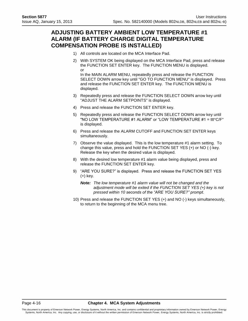
Section 5877 User Instructions Issue AQ, January 15, 2013 Spec. No. 582140000 (Models 802NLDB, 802NLEB and 802NL-B)
Page 4-16 Chapter 4. MCA System Adjustments
This document is property of Emerson Network Power, Energy Systems, North America, Inc. and contains confidential and proprietary information owned by Emerson Network Power, Energy Systems, North America, Inc. Any copying, use, or disclosure of it without the written permission of Emerson Network Power, Energy Systems, North America, Inc. is strictly prohibited.
ADJUSTING BATTERY AMBIENT LOW TEMPERATURE #1 ALARM (IF BATTERY CHARGE DIGITAL TEMPERATURE COMPENSATION PROBE IS INSTALLED)
1) All controls are located on the MCA Interface Pad.
2) With SYSTEM OK being displayed on the MCA Interface Pad, press and release the FUNCTION SET ENTER key. The FUNCTION MENU is displayed. or In the MAIN ALARM MENU, repeatedly press and release the FUNCTION SELECT DOWN arrow key until "GO TO FUNCTION MENU" is displayed. Press and release the FUNCTION SET ENTER key. The FUNCTION MENU is displayed.
3) Repeatedly press and release the FUNCTION SELECT DOWN arrow key until "ADJUST THE ALARM SETPOINTS" is displayed.
4) Press and release the FUNCTION SET ENTER key.
5) Repeatedly press and release the FUNCTION SELECT DOWN arrow key until
"NO LOW TEMPERATURE #1 ALARM” or “LOW TEMPERATURE #1 = ttt C/F" is displayed.
6) Press and release the ALARM CUTOFF and FUNCTION SET ENTER keys simultaneously.
7) Observe the value displayed. This is the low temperature #1 alarm setting. To change this value, press and hold the FUNCTION SET YES (+) or NO (-) key. Release the key when the desired value is displayed.
8) With the desired low temperature #1 alarm value being displayed, press and release the FUNCTION SET ENTER key.
9) “ARE YOU SURE?” is displayed. Press and release the FUNCTION SET YES (+) key.
Note: The low temperature #1 alarm value will not be changed and the adjustment mode will be exited if the FUNCTION SET YES (+) key is not pressed within 10 seconds of the “ARE YOU SURE?” prompt.
10) Press and release the FUNCTION SET YES (+) and NO (-) keys simultaneously, to return to the beginning of the MCA menu tree.
User Instructions Section 5877 Spec. No. 582140000 (Models 802NLDB, 802NLEB and 802NL-B) Issue AQ, January 15, 2013
Chapter 4. MCA System Adjustments Page 4-17
This document is property of Emerson Network Power, Energy Systems, North America, Inc. and contains confidential and proprietary information owned by Emerson Network Power, Energy Systems, North America, Inc. Any copying, use, or disclosure of it without the written permission of Emerson Network Power, Energy Systems, North America, Inc. is strictly prohibited.
ADJUSTING BATTERY AMBIENT LOW TEMPERATURE #2 ALARM (IF BATTERY CHARGE DIGITAL TEMPERATURE COMPENSATION PROBE IS INSTALLED)
1) All controls are located on the MCA Interface Pad.
2) With SYSTEM OK being displayed on the MCA Interface Pad, press and release the FUNCTION SET ENTER key. The FUNCTION MENU is displayed. or In the MAIN ALARM MENU, repeatedly press and release the FUNCTION SELECT DOWN arrow key until "GO TO FUNCTION MENU" is displayed. Press and release the FUNCTION SET ENTER key. The FUNCTION MENU is displayed.
3) Repeatedly press and release the FUNCTION SELECT DOWN arrow key until "ADJUST THE ALARM SETPOINTS" is displayed.
4) Press and release the FUNCTION SET ENTER key.
5) Repeatedly press and release the FUNCTION SELECT DOWN arrow key until
"NO LOW TEMPERATURE #2 ALARM” or “LOW TEMPERATURE #2 = ttt C/F" is displayed.
6) Press and release the ALARM CUTOFF and FUNCTION SET ENTER keys simultaneously.
7) Observe the value displayed. This is the low temperature #2 alarm setting. To change this value, press and hold the FUNCTION SET YES (+) or NO (-) key. Release the key when the desired value is displayed.
8) With the desired low temperature #2 alarm value being displayed, press and release the FUNCTION SET ENTER key.
9) “ARE YOU SURE?” is displayed. Press and release the FUNCTION SET YES (+) key.
Note: The low temperature #2 alarm value will not be changed and the adjustment mode will be exited if the FUNCTION SET YES (+) key is not pressed within 10 seconds of the “ARE YOU SURE?” prompt.
10) Press and release the FUNCTION SET YES (+) and NO (-) keys simultaneously, to return to the beginning of the MCA menu tree.
Section 5877 User Instructions Issue AQ, January 15, 2013 Spec. No. 582140000 (Models 802NLDB, 802NLEB and 802NL-B)
Page 4-18 Chapter 4. MCA System Adjustments
This document is property of Emerson Network Power, Energy Systems, North America, Inc. and contains confidential and proprietary information owned by Emerson Network Power, Energy Systems, North America, Inc. Any copying, use, or disclosure of it without the written permission of Emerson Network Power, Energy Systems, North America, Inc. is strictly prohibited.
CONFIGURING BATTERY CHARGE DIGITAL TEMPERATURE COMPENSATION SLOPE
Note: The Temperature Compensation feature requires Power Share to be turned off.
1) All controls are located on the MCA Interface Pad.
2) With SYSTEM OK being displayed on the MCA Interface Pad, press and release the FUNCTION SET ENTER key. The FUNCTION MENU is displayed. or In the MAIN ALARM MENU, repeatedly press and release the FUNCTION SELECT DOWN arrow key until "GO TO FUNCTION MENU" is displayed. Press and release the FUNCTION SET ENTER key. The FUNCTION MENU is displayed.
3) Repeatedly press and release the FUNCTION SELECT DOWN arrow key until "CHANGE CONFIGURATION PARAMETERS" is displayed.
4) Press and release the FUNCTION SET ENTER key.
5) Repeatedly press and release the FUNCTION SELECT DOWN arrow key until "NO TEMPERATURE COMPENSATION” or “TEMPERATURE SLOPE =
0.vvvV C/F" is displayed.
6) Press and release the ALARM CUTOFF and FUNCTION SET ENTER keys simultaneously.
7) Observe the value displayed. This is the Battery Charge Digital Temperature Compensation slope setting. To change this value, press and hold the FUNCTION SET YES (+) or NO (-) key. Release the key when the desired value is displayed.
Note: Refer to Battery and Equipment Manufacturers’ recommendations or site requirements for the value. Note that this is the compensation for the entire battery string, not per battery cell.
8) With the desired slope value being displayed, press and release the FUNCTION SET ENTER key.
9) “ARE YOU SURE?” is displayed. Press and release the FUNCTION SET YES (+) key.
Note: The slope value will not be changed and the adjustment mode will be exited if the FUNCTION SET YES (+) key is not pressed within 10 seconds of the “ARE YOU SURE?” prompt.
10) Press and release the FUNCTION SET YES (+) and NO (-) keys simultaneously, to return to the beginning of the MCA menu tree.
User Instructions Section 5877 Spec. No. 582140000 (Models 802NLDB, 802NLEB and 802NL-B) Issue AQ, January 15, 2013
Chapter 4. MCA System Adjustments Page 4-19
This document is property of Emerson Network Power, Energy Systems, North America, Inc. and contains confidential and proprietary information owned by Emerson Network Power, Energy Systems, North America, Inc. Any copying, use, or disclosure of it without the written permission of Emerson Network Power, Energy Systems, North America, Inc. is strictly prohibited.
CONFIGURING BATTERY CHARGE DIGITAL TEMPERATURE COMPENSATION MAXIMUM VOLTAGE
1) All controls are located on the MCA Interface Pad.
2) With SYSTEM OK being displayed on the MCA Interface Pad, press and release the FUNCTION SET ENTER key. The FUNCTION MENU is displayed. or In the MAIN ALARM MENU, repeatedly press and release the FUNCTION SELECT DOWN arrow key until "GO TO FUNCTION MENU" is displayed. Press and release the FUNCTION SET ENTER key. The FUNCTION MENU is displayed.
3) Repeatedly press and release the FUNCTION SELECT DOWN arrow key until "CHANGE CONFIGURATION PARAMETERS" is displayed.
4) Press and release the FUNCTION SET ENTER key.
5) Repeatedly press and release the FUNCTION SELECT DOWN arrow key until "MAXIMUM COMPENSATION = vv.vvV" is displayed.
6) Press and release the ALARM CUTOFF and FUNCTION SET ENTER keys simultaneously.
7) Observe the value displayed. This is the Battery Charge Digital Temperature Compensation maximum voltage setting. To change this value, press and hold the FUNCTION SET YES (+) or NO (-) key. Release the key when the desired value is displayed.
Note: Refer to Battery and Equipment Manufacturers’ recommendations or site requirements for the value.
Note: Maximum Voltage with Temperature Compensation is prevented from being adjusted higher than 1.0V below the High Voltage Shutdown setting, or lower than the float voltage setting.
8) With the desired maximum voltage with temperature compensation value being displayed, press and release the FUNCTION SET ENTER key.
9) “ARE YOU SURE?” is displayed. Press and release the FUNCTION SET YES (+) key.
Note: The maximum voltage with temperature compensation value will not be changed and the adjustment mode will be exited if the FUNCTION SET YES (+) key is not pressed within 10 seconds of the “ARE YOU SURE?” prompt.
10) Press and release the FUNCTION SET YES (+) and NO (-) keys simultaneously, to return to the beginning of the MCA menu tree.
Section 5877 User Instructions Issue AQ, January 15, 2013 Spec. No. 582140000 (Models 802NLDB, 802NLEB and 802NL-B)
Page 4-20 Chapter 4. MCA System Adjustments
This document is property of Emerson Network Power, Energy Systems, North America, Inc. and contains confidential and proprietary information owned by Emerson Network Power, Energy Systems, North America, Inc. Any copying, use, or disclosure of it without the written permission of Emerson Network Power, Energy Systems, North America, Inc. is strictly prohibited.
CONFIGURING BATTERY CHARGE DIGITAL TEMPERATURE COMPENSATION MINIMUM VOLTAGE
1) All controls are located on the MCA Interface Pad.
2) With SYSTEM OK being displayed on the MCA Interface Pad, press and release the FUNCTION SET ENTER key. The FUNCTION MENU is displayed. or In the MAIN ALARM MENU, repeatedly press and release the FUNCTION SELECT DOWN arrow key until "GO TO FUNCTION MENU" is displayed. Press and release the FUNCTION SET ENTER key. The FUNCTION MENU is displayed.
3) Repeatedly press and release the FUNCTION SELECT DOWN arrow key until "CHANGE CONFIGURATION PARAMETERS" is displayed.
4) Press and release the FUNCTION SET ENTER key.
5) Repeatedly press and release the FUNCTION SELECT DOWN arrow key until "MINIMUM COMPENSATION = vv.vvV" is displayed.
6) Press and release the ALARM CUTOFF and FUNCTION SET ENTER keys simultaneously.
7) Observe the value displayed. This is the Battery Charge Digital Temperature Compensation minimum voltage setting. To change this value, press and hold the FUNCTION SET YES (+) or NO (-) key. Release the key when the desired value is displayed.
Note: Refer to Battery and Equipment Manufacturers’ recommendations or site requirements for the value.
8) With the desired minimum voltage with temperature compensation value being displayed, press and release the FUNCTION SET ENTER key.
9) “ARE YOU SURE?” is displayed. Press and release the FUNCTION SET YES (+) key.
Note: The minimum voltage with temperature compensation value will not be changed and the adjustment mode will be exited if the FUNCTION SET YES (+) key is not pressed within 10 seconds of the “ARE YOU SURE?” prompt.
10) Press and release the FUNCTION SET YES (+) and NO (-) keys simultaneously, to return to the beginning of the MCA menu tree.
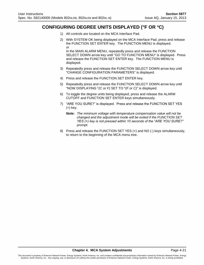
User Instructions Section 5877 Spec. No. 582140000 (Models 802NLDB, 802NLEB and 802NL-B) Issue AQ, January 15, 2013
Chapter 4. MCA System Adjustments Page 4-21
This document is property of Emerson Network Power, Energy Systems, North America, Inc. and contains confidential and proprietary information owned by Emerson Network Power, Energy Systems, North America, Inc. Any copying, use, or disclosure of it without the written permission of Emerson Network Power, Energy Systems, North America, Inc. is strictly prohibited.
CONFIGURING DEGREE UNITS DISPLAYED ( F OR C)
1) All controls are located on the MCA Interface Pad.
2) With SYSTEM OK being displayed on the MCA Interface Pad, press and release the FUNCTION SET ENTER key. The FUNCTION MENU is displayed. or In the MAIN ALARM MENU, repeatedly press and release the FUNCTION SELECT DOWN arrow key until "GO TO FUNCTION MENU" is displayed. Press and release the FUNCTION SET ENTER key. The FUNCTION MENU is displayed.
3) Repeatedly press and release the FUNCTION SELECT DOWN arrow key until "CHANGE CONFIGURATION PARAMETERS" is displayed.
4) Press and release the FUNCTION SET ENTER key.
5) Repeatedly press and release the FUNCTION SELECT DOWN arrow key until
"NOW DISPLAYING (C or F) SET TO (F or C)" is displayed.
6) To toggle the degree units being displayed, press and release the ALARM CUTOFF and FUNCTION SET ENTER keys simultaneously.
7) “ARE YOU SURE?” is displayed. Press and release the FUNCTION SET YES (+) key.
Note: The minimum voltage with temperature compensation value will not be changed and the adjustment mode will be exited if the FUNCTION SET YES (+) key is not pressed within 10 seconds of the “ARE YOU SURE?” prompt.
8) Press and release the FUNCTION SET YES (+) and NO (-) keys simultaneously, to return to the beginning of the MCA menu tree.
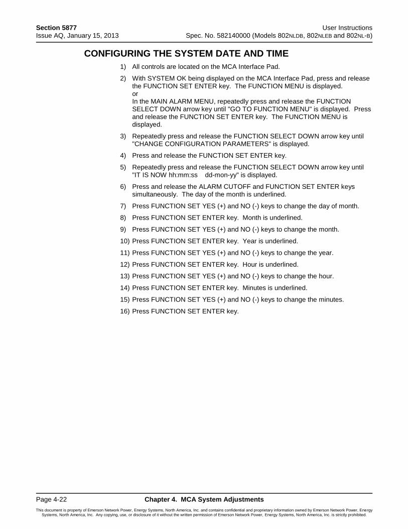
Section 5877 User Instructions Issue AQ, January 15, 2013 Spec. No. 582140000 (Models 802NLDB, 802NLEB and 802NL-B)
Page 4-22 Chapter 4. MCA System Adjustments
This document is property of Emerson Network Power, Energy Systems, North America, Inc. and contains confidential and proprietary information owned by Emerson Network Power, Energy Systems, North America, Inc. Any copying, use, or disclosure of it without the written permission of Emerson Network Power, Energy Systems, North America, Inc. is strictly prohibited.
CONFIGURING THE SYSTEM DATE AND TIME
1) All controls are located on the MCA Interface Pad.
2) With SYSTEM OK being displayed on the MCA Interface Pad, press and release the FUNCTION SET ENTER key. The FUNCTION MENU is displayed. or In the MAIN ALARM MENU, repeatedly press and release the FUNCTION SELECT DOWN arrow key until "GO TO FUNCTION MENU" is displayed. Press and release the FUNCTION SET ENTER key. The FUNCTION MENU is displayed.
3) Repeatedly press and release the FUNCTION SELECT DOWN arrow key until "CHANGE CONFIGURATION PARAMETERS" is displayed.
4) Press and release the FUNCTION SET ENTER key.
5) Repeatedly press and release the FUNCTION SELECT DOWN arrow key until "IT IS NOW hh:mm:ss dd-mon-yy" is displayed.
6) Press and release the ALARM CUTOFF and FUNCTION SET ENTER keys simultaneously. The day of the month is underlined.
7) Press FUNCTION SET YES (+) and NO (-) keys to change the day of month.
8) Press FUNCTION SET ENTER key. Month is underlined.
9) Press FUNCTION SET YES (+) and NO (-) keys to change the month.
10) Press FUNCTION SET ENTER key. Year is underlined.
11) Press FUNCTION SET YES (+) and NO (-) keys to change the year.
12) Press FUNCTION SET ENTER key. Hour is underlined.
13) Press FUNCTION SET YES (+) and NO (-) keys to change the hour.
14) Press FUNCTION SET ENTER key. Minutes is underlined.
15) Press FUNCTION SET YES (+) and NO (-) keys to change the minutes.
16) Press FUNCTION SET ENTER key.
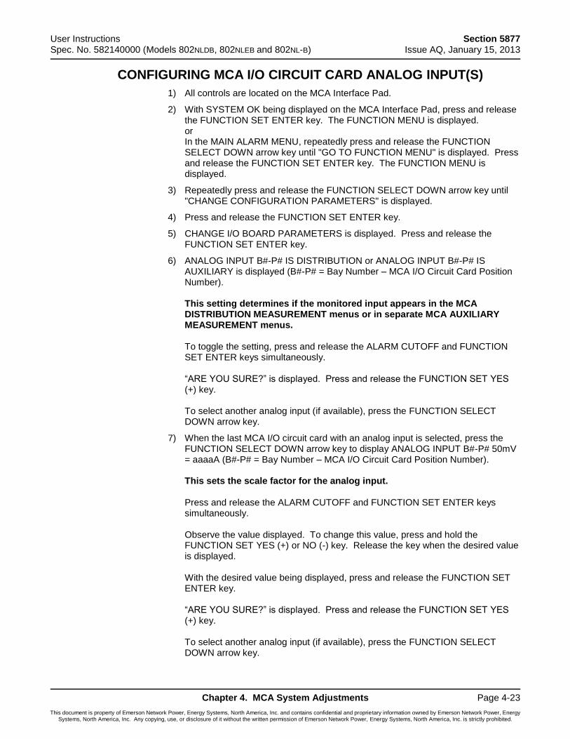
User Instructions Section 5877 Spec. No. 582140000 (Models 802NLDB, 802NLEB and 802NL-B) Issue AQ, January 15, 2013
Chapter 4. MCA System Adjustments Page 4-23
This document is property of Emerson Network Power, Energy Systems, North America, Inc. and contains confidential and proprietary information owned by Emerson Network Power, Energy Systems, North America, Inc. Any copying, use, or disclosure of it without the written permission of Emerson Network Power, Energy Systems, North America, Inc. is strictly prohibited.
CONFIGURING MCA I/O CIRCUIT CARD ANALOG INPUT(S)
1) All controls are located on the MCA Interface Pad.
2) With SYSTEM OK being displayed on the MCA Interface Pad, press and release the FUNCTION SET ENTER key. The FUNCTION MENU is displayed. or In the MAIN ALARM MENU, repeatedly press and release the FUNCTION SELECT DOWN arrow key until "GO TO FUNCTION MENU" is displayed. Press and release the FUNCTION SET ENTER key. The FUNCTION MENU is displayed.
3) Repeatedly press and release the FUNCTION SELECT DOWN arrow key until "CHANGE CONFIGURATION PARAMETERS" is displayed.
4) Press and release the FUNCTION SET ENTER key.
5) CHANGE I/O BOARD PARAMETERS is displayed. Press and release the FUNCTION SET ENTER key.
6) ANALOG INPUT B#-P# IS DISTRIBUTION or ANALOG INPUT B#-P# IS AUXILIARY is displayed (B#-P# = Bay Number – MCA I/O Circuit Card Position Number). This setting determines if the monitored input appears in the MCA DISTRIBUTION MEASUREMENT menus or in separate MCA AUXILIARY MEASUREMENT menus. To toggle the setting, press and release the ALARM CUTOFF and FUNCTION SET ENTER keys simultaneously. “ARE YOU SURE?” is displayed. Press and release the FUNCTION SET YES (+) key. To select another analog input (if available), press the FUNCTION SELECT DOWN arrow key.
7) When the last MCA I/O circuit card with an analog input is selected, press the FUNCTION SELECT DOWN arrow key to display ANALOG INPUT B#-P# 50mV = aaaaA (B#-P# = Bay Number – MCA I/O Circuit Card Position Number). This sets the scale factor for the analog input. Press and release the ALARM CUTOFF and FUNCTION SET ENTER keys simultaneously. Observe the value displayed. To change this value, press and hold the FUNCTION SET YES (+) or NO (-) key. Release the key when the desired value is displayed. With the desired value being displayed, press and release the FUNCTION SET ENTER key. “ARE YOU SURE?” is displayed. Press and release the FUNCTION SET YES (+) key. To select another analog input (if available), press the FUNCTION SELECT DOWN arrow key.
Section 5877 User Instructions Issue AQ, January 15, 2013 Spec. No. 582140000 (Models 802NLDB, 802NLEB and 802NL-B)
Page 4-24 Chapter 4. MCA System Adjustments
This document is property of Emerson Network Power, Energy Systems, North America, Inc. and contains confidential and proprietary information owned by Emerson Network Power, Energy Systems, North America, Inc. Any copying, use, or disclosure of it without the written permission of Emerson Network Power, Energy Systems, North America, Inc. is strictly prohibited.
8) Press and release the FUNCTION SET YES (+) and NO (-) keys simultaneously, to return to the beginning of the MCA menu tree.
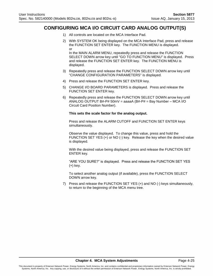
User Instructions Section 5877 Spec. No. 582140000 (Models 802NLDB, 802NLEB and 802NL-B) Issue AQ, January 15, 2013
Chapter 4. MCA System Adjustments Page 4-25
This document is property of Emerson Network Power, Energy Systems, North America, Inc. and contains confidential and proprietary information owned by Emerson Network Power, Energy Systems, North America, Inc. Any copying, use, or disclosure of it without the written permission of Emerson Network Power, Energy Systems, North America, Inc. is strictly prohibited.
CONFIGURING MCA I/O CIRCUIT CARD ANALOG OUTPUT(S)
1) All controls are located on the MCA Interface Pad.
2) With SYSTEM OK being displayed on the MCA Interface Pad, press and release the FUNCTION SET ENTER key. The FUNCTION MENU is displayed. or In the MAIN ALARM MENU, repeatedly press and release the FUNCTION SELECT DOWN arrow key until "GO TO FUNCTION MENU" is displayed. Press and release the FUNCTION SET ENTER key. The FUNCTION MENU is displayed.
3) Repeatedly press and release the FUNCTION SELECT DOWN arrow key until "CHANGE CONFIGURATION PARAMETERS" is displayed.
4) Press and release the FUNCTION SET ENTER key.
5) CHANGE I/O BOARD PARAMETERS is displayed. Press and release the FUNCTION SET ENTER key.
6) Repeatedly press and release the FUNCTION SELECT DOWN arrow key until ANALOG OUTPUT B#-P# 50mV = aaaaA (B#-P# = Bay Number – MCA I/O Circuit Card Position Number). This sets the scale factor for the analog output. Press and release the ALARM CUTOFF and FUNCTION SET ENTER keys simultaneously. Observe the value displayed. To change this value, press and hold the FUNCTION SET YES (+) or NO (-) key. Release the key when the desired value is displayed. With the desired value being displayed, press and release the FUNCTION SET ENTER key. “ARE YOU SURE?” is displayed. Press and release the FUNCTION SET YES (+) key. To select another analog output (if available), press the FUNCTION SELECT DOWN arrow key.
7) Press and release the FUNCTION SET YES (+) and NO (-) keys simultaneously, to return to the beginning of the MCA menu tree.
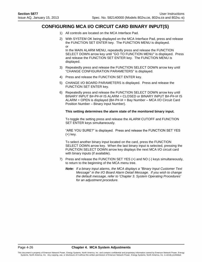
Section 5877 User Instructions Issue AQ, January 15, 2013 Spec. No. 582140000 (Models 802NLDB, 802NLEB and 802NL-B)
Page 4-26 Chapter 4. MCA System Adjustments
This document is property of Emerson Network Power, Energy Systems, North America, Inc. and contains confidential and proprietary information owned by Emerson Network Power, Energy Systems, North America, Inc. Any copying, use, or disclosure of it without the written permission of Emerson Network Power, Energy Systems, North America, Inc. is strictly prohibited.
CONFIGURING MCA I/O CIRCUIT CARD BINARY INPUT(S)
1) All controls are located on the MCA Interface Pad.
2) With SYSTEM OK being displayed on the MCA Interface Pad, press and release the FUNCTION SET ENTER key. The FUNCTION MENU is displayed. or In the MAIN ALARM MENU, repeatedly press and release the FUNCTION SELECT DOWN arrow key until "GO TO FUNCTION MENU" is displayed. Press and release the FUNCTION SET ENTER key. The FUNCTION MENU is displayed.
3) Repeatedly press and release the FUNCTION SELECT DOWN arrow key until "CHANGE CONFIGURATION PARAMETERS" is displayed.
4) Press and release the FUNCTION SET ENTER key.
5) CHANGE I/O BOARD PARAMETERS is displayed. Press and release the FUNCTION SET ENTER key.
6) Repeatedly press and release the FUNCTION SELECT DOWN arrow key until BINARY INPUT B#-P#-I# IS ALARM = CLOSED or BINARY INPUT B#-P#-I# IS ALARM = OPEN is displayed (B#-P#-I# = Bay Number – MCA I/O Circuit Card Position Number – Binary Input Number). This setting determines the alarm state of the monitored binary input. To toggle the setting press and release the ALARM CUTOFF and FUNCTION SET ENTER keys simultaneously. “ARE YOU SURE?” is displayed. Press and release the FUNCTION SET YES (+) key. To select another binary input located on the card, press the FUNCTION SELECT DOWN arrow key. When the last binary input is selected, pressing the FUNCTION SELECT DOWN arrow key displays the next MCA I/O circuit card with binary inputs (if available).
7) Press and release the FUNCTION SET YES (+) and NO (-) keys simultaneously, to return to the beginning of the MCA menu tree.
Note: If a binary input alarms, the MCA displays a "Binary Input Customer Text Message" in the I/O Board Alarm Detail Message. If you wish to change the default message, refer to 'Chapter 3. System Operating Procedures' for an adjustment procedure.
User Instructions Section 5877 Spec. No. 582140000 (Models 802NLDB, 802NLEB and 802NL-B) Issue AQ, January 15, 2013
Chapter 4. MCA System Adjustments Page 4-27
This document is property of Emerson Network Power, Energy Systems, North America, Inc. and contains confidential and proprietary information owned by Emerson Network Power, Energy Systems, North America, Inc. Any copying, use, or disclosure of it without the written permission of Emerson Network Power, Energy Systems, North America, Inc. is strictly prohibited.
MCA AUDIBLE ALARM CUTOFF RESET TIME PERIOD
Refer to Chapter 3. System Operating Procedures for an adjustment procedure.
MCA RECTIFIER SEQUENCING FEATURE
Refer to Chapter 3. System Operating Procedures for an adjustment procedure.
MANUALLY INITIATED TIMED TEST/EQUALIZE FEATURE
Refer to Chapter 3. System Operating Procedures for an adjustment procedure.
AUTOMATIC TEST/EQUALIZE FEATURE
Refer to Chapter 3. System Operating Procedures for an adjustment procedure.
MCA POWER SHARE FEATURE
Refer to Chapter 3. System Operating Procedures for an adjustment procedure.
ALARM RELAY TEST FEATURE
Refer to Setting and Testing MCA Customer Alarm Relays in "Chapter 5. Installing the Rectifiers and Initially Starting the System" in the separate INSTALLATION INSTRUCTIONS (Section 5876).
MCA “ALTERNATE CURRENT LIMIT” FEATURE
Refer to Chapter 3. System Operating Procedures for an adjustment procedure.
Section 5877 User Instructions Issue AQ, January 15, 2013 Spec. No. 582140000 (Models 802NLDB, 802NLEB and 802NL-B)
Page 4-28 Chapter 4. MCA System Adjustments
This document is property of Emerson Network Power, Energy Systems, North America, Inc. and contains confidential and proprietary information owned by Emerson Network Power, Energy Systems, North America, Inc. Any copying, use, or disclosure of it without the written permission of Emerson Network Power, Energy Systems, North America, Inc. is strictly prohibited.
This Page Intentionally Left Blank
User Instructions Section 5877 Spec. No. 582140000 (Models 802NLDB, 802NLEB and 802NL-B) Issue AQ, January 15, 2013
Chapter 5. System Maintenance Page 5-1
This document is property of Emerson Network Power, Energy Systems, North America, Inc. and contains confidential and proprietary information owned by Emerson Network Power, Energy Systems, North America, Inc. Any copying, use, or disclosure of it without the written permission of Emerson Network Power, Energy Systems, North America, Inc. is strictly prohibited.
CHAPTER 5 SYSTEM MAINTENANCE
TABLE OF CONTENTS
Admonishments ............................................................................................................... 5-2
General Safety .......................................................................................................... 5-2
Voltages .................................................................................................................... 5-2
LMS Maintenance Procedures ........................................................................................ 5-2
System Maintenance Procedures ................................................................................... 5-3
Adding a Rectifier ............................................................................................................ 5-8
Section 5877 User Instructions Issue AQ, January 15, 2013 Spec. No. 582140000 (Models 802NLDB, 802NLEB and 802NL-B)
Page 5-2 Chapter 5. System Maintenance
This document is property of Emerson Network Power, Energy Systems, North America, Inc. and contains confidential and proprietary information owned by Emerson Network Power, Energy Systems, North America, Inc. Any copying, use, or disclosure of it without the written permission of Emerson Network Power, Energy Systems, North America, Inc. is strictly prohibited.
ADMONISHMENTS
General Safety
Danger: SERVICE PERSONNEL MUST FOLLOW APPROVED SAFETY PROCEDURES. Performing the following procedures may expose service personnel to hazards. These procedures should be performed by qualified service personnel familiar with the hazards associated with this type of equipment. These hazards may include shock, energy, and/or burns. To avoid these hazards:
a) The tasks should be performed in the order indicated.
b) Remove watches, rings, and other jewelry.
c) Prior to contacting any uninsulated surface or termination, use a voltmeter to verify that no voltage or the expected voltage is present.
d) Wear eye protection, and use recommended tools.
e) Use insulated tools.
(To avoid danger to the installer or damage to the equipment, the tools used in this procedure should have insulated grips. All exposed metal shafts, extensions, handles, etc. should be completely insulated with a minimum of three half-lapped layers of electrical tape. Ensure that wrenches with more than one working end have only one end exposed.)
Voltages
AC Input Voltages
Danger: This system operates from AC voltage capable of producing fatal electrical shock.
DC Input/Output Voltages
Danger: This system produces DC Power and requires battery to be connected to it. Although the DC voltage is not hazardously high, the rectifier modules and/or battery can deliver large amounts of current. Exercise extreme caution not to inadvertently contact or have any tool inadvertently contact a battery terminal or exposed wire connected to a battery terminal. NEVER allow a metal object, such as a tool, to contact more than one termination at a time, or to simultaneously contact a termination and a grounded object. Even a momentary short circuit can cause explosion and injury.
LMS MAINTENANCE PROCEDURES
Refer to the LMS User Instructions (Section 5847) for LMS maintenance procedures. Section 5847 can be accessed via the CD (Electronic Documentation Package) furnished with your system.
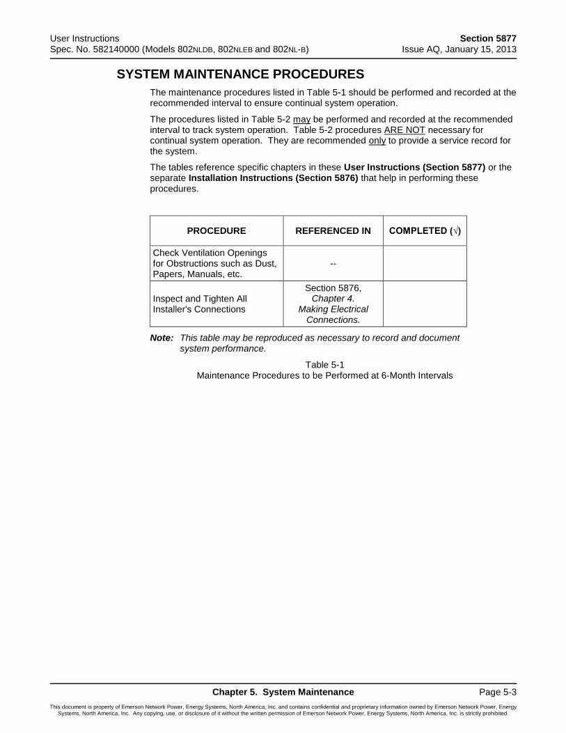
User Instructions Section 5877 Spec. No. 582140000 (Models 802NLDB, 802NLEB and 802NL-B) Issue AQ, January 15, 2013
Chapter 5. System Maintenance Page 5-3
This document is property of Emerson Network Power, Energy Systems, North America, Inc. and contains confidential and proprietary information owned by Emerson Network Power, Energy Systems, North America, Inc. Any copying, use, or disclosure of it without the written permission of Emerson Network Power, Energy Systems, North America, Inc. is strictly prohibited.
SYSTEM MAINTENANCE PROCEDURES
The maintenance procedures listed in Table 5-1 should be performed and recorded at the recommended interval to ensure continual system operation.
The procedures listed in Table 5-2 may be performed and recorded at the recommended interval to track system operation. Table 5-2 procedures ARE NOT necessary for continual system operation. They are recommended only to provide a service record for the system.
The tables reference specific chapters in these User Instructions (Section 5877) or the separate Installation Instructions (Section 5876) that help in performing these procedures.
PROCEDURE REFERENCED IN COMPLETED (√)
Check Ventilation Openings for Obstructions such as Dust, Papers, Manuals, etc.
--
Inspect and Tighten All Installer's Connections
Section 5876, Chapter 4.
Making Electrical Connections.
Note: This table may be reproduced as necessary to record and document system performance.
Table 5-1 Maintenance Procedures to be Performed at 6-Month Intervals
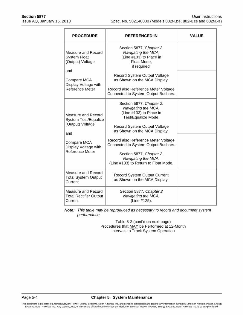
Section 5877 User Instructions Issue AQ, January 15, 2013 Spec. No. 582140000 (Models 802NLDB, 802NLEB and 802NL-B)
Page 5-4 Chapter 5. System Maintenance
This document is property of Emerson Network Power, Energy Systems, North America, Inc. and contains confidential and proprietary information owned by Emerson Network Power, Energy Systems, North America, Inc. Any copying, use, or disclosure of it without the written permission of Emerson Network Power, Energy Systems, North America, Inc. is strictly prohibited.
PROCEDURE REFERENCED IN VALUE
Measure and Record System Float (Output) Voltage and Compare MCA Display Voltage with Reference Meter
Section 5877, Chapter 2. Navigating the MCA,
(Line #133) to Place in Float Mode, if required.
Record System Output Voltage as Shown on the MCA Display.
Record also Reference Meter Voltage Connected to System Output Busbars.
Measure and Record System Test/Equalize (Output) Voltage and Compare MCA Display Voltage with Reference Meter
Section 5877, Chapter 2. Navigating the MCA,
(Line #133) to Place in Test/Equalize Mode.
Record System Output Voltage as Shown on the MCA Display.
Record also Reference Meter Voltage Connected to System Output Busbars.
Section 5877, Chapter 2.
Navigating the MCA, (Line #133) to Return to Float Mode.
Measure and Record Total System Output Current
Record System Output Current as Shown on the MCA Display.
Measure and Record Total Rectifier Output Current
Section 5877, Chapter 2 Navigating the MCA,
(Line #125).
Note: This table may be reproduced as necessary to record and document system performance.
Table 5-2 (cont’d on next page) Procedures that MAY be Performed at 12-Month
Intervals to Track System Operation
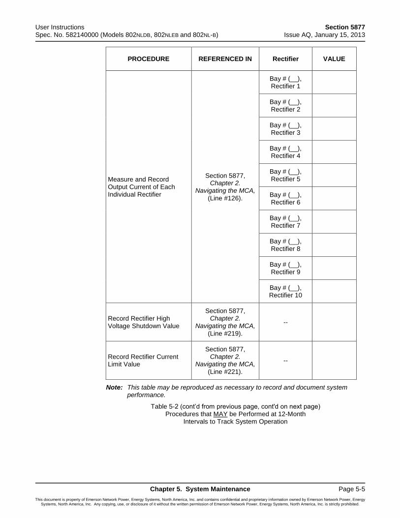
User Instructions Section 5877 Spec. No. 582140000 (Models 802NLDB, 802NLEB and 802NL-B) Issue AQ, January 15, 2013
Chapter 5. System Maintenance Page 5-5
This document is property of Emerson Network Power, Energy Systems, North America, Inc. and contains confidential and proprietary information owned by Emerson Network Power, Energy Systems, North America, Inc. Any copying, use, or disclosure of it without the written permission of Emerson Network Power, Energy Systems, North America, Inc. is strictly prohibited.
PROCEDURE REFERENCED IN Rectifier VALUE
Measure and Record Output Current of Each Individual Rectifier
Section 5877, Chapter 2.
Navigating the MCA, (Line #126).
Bay # (__), Rectifier 1
Bay # (__), Rectifier 2
Bay # (__), Rectifier 3
Bay # (__), Rectifier 4
Bay # (__), Rectifier 5
Bay # (__), Rectifier 6
Bay # (__), Rectifier 7
Bay # (__), Rectifier 8
Bay # (__), Rectifier 9
Bay # (__), Rectifier 10
Record Rectifier High Voltage Shutdown Value
Section 5877, Chapter 2.
Navigating the MCA, (Line #219).
--
Record Rectifier Current Limit Value
Section 5877, Chapter 2.
Navigating the MCA, (Line #221).
--
Note: This table may be reproduced as necessary to record and document system performance.
Table 5-2 (cont’d from previous page, cont'd on next page) Procedures that MAY be Performed at 12-Month
Intervals to Track System Operation
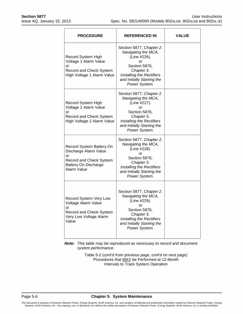
Section 5877 User Instructions Issue AQ, January 15, 2013 Spec. No. 582140000 (Models 802NLDB, 802NLEB and 802NL-B)
Page 5-6 Chapter 5. System Maintenance
This document is property of Emerson Network Power, Energy Systems, North America, Inc. and contains confidential and proprietary information owned by Emerson Network Power, Energy Systems, North America, Inc. Any copying, use, or disclosure of it without the written permission of Emerson Network Power, Energy Systems, North America, Inc. is strictly prohibited.
PROCEDURE REFERENCED IN VALUE
Record System High Voltage 1 Alarm Value or Record and Check System High Voltage 1 Alarm Value
Section 5877, Chapter 2. Navigating the MCA,
(Line #226). or
Section 5876, Chapter 5.
Installing the Rectifiers and Initially Starting the
Power System.
Record System High Voltage 2 Alarm Value or Record and Check System High Voltage 2 Alarm Value
Section 5877, Chapter 2. Navigating the MCA,
(Line #227). or
Section 5876, Chapter 5.
Installing the Rectifiers and Initially Starting the
Power System.
Record System Battery On Discharge Alarm Value or Record and Check System Battery On Discharge Alarm Value
Section 5877, Chapter 2. Navigating the MCA,
(Line #228). or
Section 5876, Chapter 5.
Installing the Rectifiers and Initially Starting the
Power System.
Record System Very Low Voltage Alarm Value or Record and Check System Very Low Voltage Alarm Value
Section 5877, Chapter 2. Navigating the MCA,
(Line #229). or
Section 5876, Chapter 5.
Installing the Rectifiers and Initially Starting the
Power System.
Note: This table may be reproduced as necessary to record and document system performance.
Table 5-2 (cont'd from previous page, cont'd on next page) Procedures that MAY be Performed at 12-Month
Intervals to Track System Operation
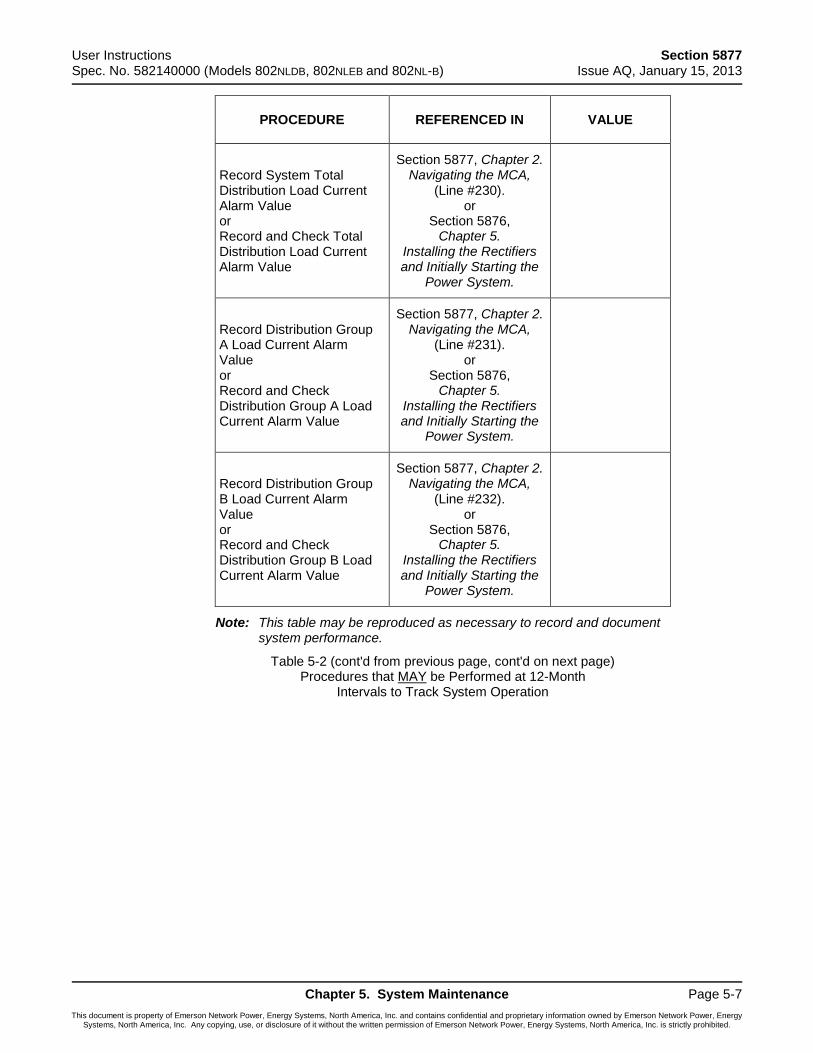
User Instructions Section 5877 Spec. No. 582140000 (Models 802NLDB, 802NLEB and 802NL-B) Issue AQ, January 15, 2013
Chapter 5. System Maintenance Page 5-7
This document is property of Emerson Network Power, Energy Systems, North America, Inc. and contains confidential and proprietary information owned by Emerson Network Power, Energy Systems, North America, Inc. Any copying, use, or disclosure of it without the written permission of Emerson Network Power, Energy Systems, North America, Inc. is strictly prohibited.
PROCEDURE REFERENCED IN VALUE
Record System Total Distribution Load Current Alarm Value or Record and Check Total Distribution Load Current Alarm Value
Section 5877, Chapter 2. Navigating the MCA,
(Line #230). or
Section 5876, Chapter 5.
Installing the Rectifiers and Initially Starting the
Power System.
Record Distribution Group A Load Current Alarm Value or Record and Check Distribution Group A Load Current Alarm Value
Section 5877, Chapter 2. Navigating the MCA,
(Line #231). or
Section 5876, Chapter 5.
Installing the Rectifiers and Initially Starting the
Power System.
Record Distribution Group B Load Current Alarm Value or Record and Check Distribution Group B Load Current Alarm Value
Section 5877, Chapter 2. Navigating the MCA,
(Line #232). or
Section 5876, Chapter 5.
Installing the Rectifiers and Initially Starting the
Power System.
Note: This table may be reproduced as necessary to record and document system performance.
Table 5-2 (cont'd from previous page, cont'd on next page) Procedures that MAY be Performed at 12-Month
Intervals to Track System Operation
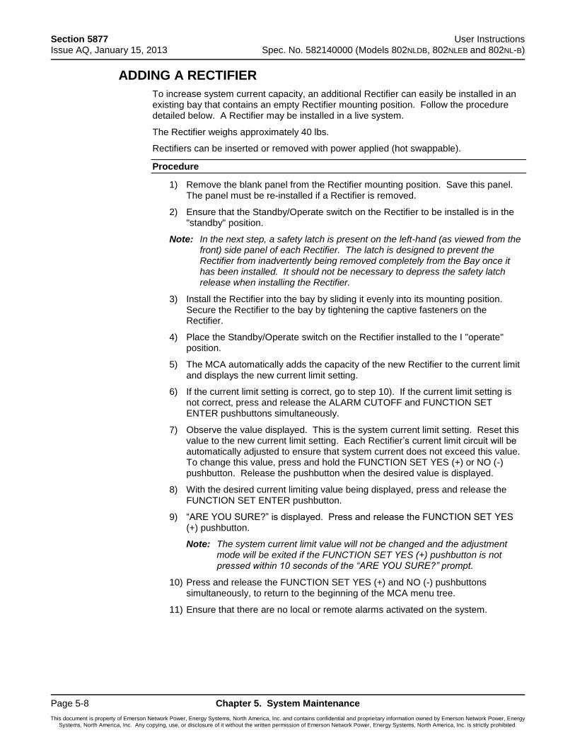
Section 5877 User Instructions Issue AQ, January 15, 2013 Spec. No. 582140000 (Models 802NLDB, 802NLEB and 802NL-B)
Page 5-8 Chapter 5. System Maintenance
This document is property of Emerson Network Power, Energy Systems, North America, Inc. and contains confidential and proprietary information owned by Emerson Network Power, Energy Systems, North America, Inc. Any copying, use, or disclosure of it without the written permission of Emerson Network Power, Energy Systems, North America, Inc. is strictly prohibited.
ADDING A RECTIFIER
To increase system current capacity, an additional Rectifier can easily be installed in an existing bay that contains an empty Rectifier mounting position. Follow the procedure detailed below. A Rectifier may be installed in a live system.
The Rectifier weighs approximately 40 lbs.
Rectifiers can be inserted or removed with power applied (hot swappable).
Procedure
1) Remove the blank panel from the Rectifier mounting position. Save this panel. The panel must be re-installed if a Rectifier is removed.
2) Ensure that the Standby/Operate switch on the Rectifier to be installed is in the "standby" position.
Note: In the next step, a safety latch is present on the left-hand (as viewed from the front) side panel of each Rectifier. The latch is designed to prevent the Rectifier from inadvertently being removed completely from the Bay once it has been installed. It should not be necessary to depress the safety latch release when installing the Rectifier.
3) Install the Rectifier into the bay by sliding it evenly into its mounting position. Secure the Rectifier to the bay by tightening the captive fasteners on the Rectifier.
4) Place the Standby/Operate switch on the Rectifier installed to the I "operate" position.
5) The MCA automatically adds the capacity of the new Rectifier to the current limit and displays the new current limit setting.
6) If the current limit setting is correct, go to step 10). If the current limit setting is not correct, press and release the ALARM CUTOFF and FUNCTION SET ENTER pushbuttons simultaneously.
7) Observe the value displayed. This is the system current limit setting. Reset this value to the new current limit setting. Each Rectifier’s current limit circuit will be automatically adjusted to ensure that system current does not exceed this value. To change this value, press and hold the FUNCTION SET YES (+) or NO (-) pushbutton. Release the pushbutton when the desired value is displayed.
8) With the desired current limiting value being displayed, press and release the FUNCTION SET ENTER pushbutton.
9) “ARE YOU SURE?” is displayed. Press and release the FUNCTION SET YES (+) pushbutton.
Note: The system current limit value will not be changed and the adjustment mode will be exited if the FUNCTION SET YES (+) pushbutton is not pressed within 10 seconds of the “ARE YOU SURE?” prompt.
10) Press and release the FUNCTION SET YES (+) and NO (-) pushbuttons simultaneously, to return to the beginning of the MCA menu tree.
11) Ensure that there are no local or remote alarms activated on the system.
User Instructions Section 5877 Spec. No. 582140000 (Models 802NLDB, 802NLEB and 802NL-B) Issue AQ, January 15, 2013
Chapter 6. System Troubleshooting and Repair Page 6-1
This document is property of Emerson Network Power, Energy Systems, North America, Inc. and contains confidential and proprietary information owned by Emerson Network Power, Energy Systems, North America, Inc. Any copying, use, or disclosure of it without the written permission of Emerson Network Power, Energy Systems, North America, Inc. is strictly prohibited.
CHAPTER 6 SYSTEM TROUBLESHOOTING AND REPAIR
CONTACT INFORMATION
Support contact information is provided on the inside of the back cover of this document.
TABLE OF CONTENTS
Contact Information ......................................................................................................... 6-1
Admonishments ............................................................................................................... 6-2
General Safety .......................................................................................................... 6-2
Voltages .................................................................................................................... 6-2
Circuit Card Handling ................................................................................................ 6-3
LMS Troubleshooting Procedures ................................................................................... 6-3
Troubleshooting Information ............................................................................................ 6-4
General ..................................................................................................................... 6-4
Adjustments .............................................................................................................. 6-4
MCA Messages ......................................................................................................... 6-4
Rectifier Current Sharing Unbalance ........................................................................ 6-5
Rectifier Module Fault Symptoms and Troubleshooting ........................................... 6-6
Updating the Inventory after Changes to the System Have Been Made .................. 6-7
Replacement Information ................................................................................................ 6-8
Replacement Assemblies ......................................................................................... 6-8
Replacement Cables ................................................................................................. 6-8
Replacement Procedures ................................................................................................ 6-9
Rectifier Replacement ............................................................................................... 6-9
MCA Circuit Card Replacement .............................................................................. 6-11
Router Circuit Card Replacement ........................................................................... 6-15
Distribution Bus Monitoring Circuit Card Replacement........................................... 6-18
MCA Customer Alarm Relay Circuit Card Replacement ........................................ 6-21
MCA I/O Circuit Card Replacement ........................................................................ 6-21
Alarm, Reference, and Control Fuse Replacement ................................................ 6-22
Rectifier Fan Replacement ..................................................................................... 6-25
Adding a Battery Charge Digital Temperature Compensation Probe to a Previously Operated System ......................................................................................... 6-26
Removing a Battery Charge Digital Temperature Compensation Probe from a Previously Operated System ......................................................................................... 6-27
Section 5877 User Instructions Issue AQ, January 15, 2013 Spec. No. 582140000 (Models 802NLDB, 802NLEB and 802NL-B)
Page 6-2 Chapter 6. System Troubleshooting and Repair
This document is property of Emerson Network Power, Energy Systems, North America, Inc. and contains confidential and proprietary information owned by Emerson Network Power, Energy Systems, North America, Inc. Any copying, use, or disclosure of it without the written permission of Emerson Network Power, Energy Systems, North America, Inc. is strictly prohibited.
ADMONISHMENTS
General Safety
Danger: SERVICE PERSONNEL MUST FOLLOW APPROVED SAFETY PROCEDURES. Performing the following procedures may expose service personnel to hazards. These procedures should be performed by qualified service personnel familiar with the hazards associated with this type of equipment. These hazards may include shock, energy, and/or burns. To avoid these hazards:
a) The tasks should be performed in the order indicated.
b) Remove watches, rings, and other jewelry.
c) Prior to contacting any uninsulated surface or termination, use a voltmeter to verify that no voltage or the expected voltage is present.
d) Wear eye protection, and use recommended tools.
e) Use insulated tools.
(To avoid danger to the installer or damage to the equipment, the tools used in this procedure should have insulated grips. All exposed metal shafts, extensions, handles, etc. should be completely insulated with a minimum of three half-lapped layers of electrical tape. Ensure that wrenches with more than one working end have only one end exposed.)
Voltages
AC Input Voltages
Danger: This system operates from AC voltage capable of producing fatal electrical shock.
DC Input/Output Voltages
Danger: This system produces DC Power and requires battery to be connected to it. Although the DC voltage is not hazardously high, the rectifier Modules and/or battery can deliver large amounts of current. Exercise extreme caution not to inadvertently contact or have any tool inadvertently contact a battery terminal or exposed wire connected to a battery terminal. NEVER allow a metal object, such as a tool, to contact more than one termination at a time, or to simultaneously contact a termination and a grounded object. Even a momentary short circuit can cause explosion and injury.
Caution: Performing the following procedures may interrupt power to the loads, if battery reserve is not sufficient.
User Instructions Section 5877 Spec. No. 582140000 (Models 802NLDB, 802NLEB and 802NL-B) Issue AQ, January 15, 2013
Chapter 6. System Troubleshooting and Repair Page 6-3
This document is property of Emerson Network Power, Energy Systems, North America, Inc. and contains confidential and proprietary information owned by Emerson Network Power, Energy Systems, North America, Inc. Any copying, use, or disclosure of it without the written permission of Emerson Network Power, Energy Systems, North America, Inc. is strictly prohibited.
Circuit Card Handling
Warning: Installation or removal of the circuit cards requires careful handling. Before handling any circuit card, read and follow the instructions contained on the Static Warning Page located at the beginning of this manual. DC input power should always be removed from a circuit card before inserting or removing a circuit card. To avoid possibility of circuit card damage from static discharge, a static wrist strap grounded through a one megohm resistor should always be worn when handling the circuit cards.
LMS TROUBLESHOOTING PROCEDURES
Refer to the LMS User Instructions (Section 5847) for LMS troubleshooting procedures. Section 5847 can be accessed via the CD (Electronic Documentation Package) furnished with your system.
Section 5877 User Instructions Issue AQ, January 15, 2013 Spec. No. 582140000 (Models 802NLDB, 802NLEB and 802NL-B)
Page 6-4 Chapter 6. System Troubleshooting and Repair
This document is property of Emerson Network Power, Energy Systems, North America, Inc. and contains confidential and proprietary information owned by Emerson Network Power, Energy Systems, North America, Inc. Any copying, use, or disclosure of it without the written permission of Emerson Network Power, Energy Systems, North America, Inc. is strictly prohibited.
TROUBLESHOOTING INFORMATION
General
This system is designed for ease in troubleshooting and repair. The various indicators, as described in Chapter 3. System Operating Procedures, are designed to isolate a failure to a specific element. Once the faulty element has been identified, refer to the next sections, “Replacement Information” and "Replacement Procedures".
The procedures listed in Chapter 5. System Maintenance, can also be used by servicing personnel in identification and/or prevention of trouble symptoms in the system.
Adjustments
If the suspected cause of a trouble symptom is an out of adjustment condition, that particular adjustment setting should be checked or reset using the appropriate adjustment procedure detailed in Chapter 4. MCA System Adjustments. If a failed Rectifier or circuit card is suspected, the adjustment procedures can also be used to verify the setpoints as well as the operation of the Rectifier or circuit card.
MCA Messages
An MCA Menu Tree (Section 5886) is provided in the separate INSTALLATION MANUAL and the CD CARRIER MANUAL (it is also provided on the CD). Each line in the MCA Menu Tree contains a number. This number is referenced in a chart provided in Chapter 2. Navigating the MCA. This chart provides a description of each line listed on the MCA Menu Tree.
If the MCA displays an alarm message, find the line in the MCA Menu Tree showing this message. For an explanation of this alarm, locate the corresponding MCA Menu Tree Line Number in the chart provided in Chapter 2. Navigating the MCA.
Note: If the MCA is replaced with an MCA previously used in another power system, the MCA may reflect inventory items not in the current power system and may display alarms. In this case, update the inventory as detailed in this chapter. Also, if you remove an inventory item (a component) from the power system, you must update the inventory to clear alarms.
Note: If you remove a Battery Charge Digital Temperature Compensation Probe, alarms are displayed. Manually set the Battery Charge Digital Temperature Compensation feature to off as described in "Chapter 4. MCA System Adjustments" to clear the alarms.
User Instructions Section 5877 Spec. No. 582140000 (Models 802NLDB, 802NLEB and 802NL-B) Issue AQ, January 15, 2013
Chapter 6. System Troubleshooting and Repair Page 6-5
This document is property of Emerson Network Power, Energy Systems, North America, Inc. and contains confidential and proprietary information owned by Emerson Network Power, Energy Systems, North America, Inc. Any copying, use, or disclosure of it without the written permission of Emerson Network Power, Energy Systems, North America, Inc. is strictly prohibited.
Rectifier Current Sharing Unbalance
When multiple rectifiers are operating in parallel and the current sharing unbalance among them is greater than 3%, check if the communications cables are correctly connected.
If the current sharing unbalance still persists, following the verification suggested above, then replace the rectifier which has had its current sharing function disabled.
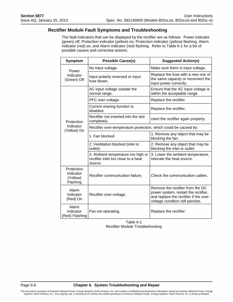
Section 5877 User Instructions Issue AQ, January 15, 2013 Spec. No. 582140000 (Models 802NLDB, 802NLEB and 802NL-B)
Page 6-6 Chapter 6. System Troubleshooting and Repair
This document is property of Emerson Network Power, Energy Systems, North America, Inc. and contains confidential and proprietary information owned by Emerson Network Power, Energy Systems, North America, Inc. Any copying, use, or disclosure of it without the written permission of Emerson Network Power, Energy Systems, North America, Inc. is strictly prohibited.
Rectifier Module Fault Symptoms and Troubleshooting
The fault indicators that can be displayed by the rectifier are as follows: Power indicator (green) off, Protection indicator (yellow) on, Protection indicator (yellow) flashing, Alarm indicator (red) on, and Alarm indicator (red) flashing. Refer to Table 6-1 for a list of possible causes and corrective actions.
Symptom Possible Cause(s) Suggested Action(s)
Power Indicator
(Green) Off
No input voltage. Make sure there is input voltage.
Input polarity reversed or input fuse blown.
Replace the fuse with a new one of the same capacity or reconnect the input power correctly.
Protection Indicator
(Yellow) On
AC input voltage outside the normal range.
Ensure that the AC input voltage is within the acceptable range.
PFC over-voltage. Replace the rectifier.
Current sharing function is disabled.
Replace the rectifier.
Rectifier not inserted into the slot completely.
nsert the rectifier again properly.
Rectifier over-temperature protection, which could be caused by:
1. Fan blocked. 1. Remove any object that may be blocking the fan.
2. Ventilation blocked (inlet or outlet).
2. Remove any object that may be blocking the inlet or outlet.
3. Ambient temperature too high or rectifier inlet too close to a heat source.
3. Lower the ambient temperature, relocate the heat source.
Protection Indicator (Yellow) Flashing
Rectifier communication failure. Check the communication cables.
Alarm Indicator (Red) On
Rectifier over-voltage.
Remove the rectifier from the DC power system, restart the rectifier, and replace the rectifier if the over-voltage condition still persists.
Alarm Indicator
(Red) Flashing Fan not operating. Replace the rectifier.
Table 6-1 Rectifier Module Troubleshooting
User Instructions Section 5877 Spec. No. 582140000 (Models 802NLDB, 802NLEB and 802NL-B) Issue AQ, January 15, 2013
Chapter 6. System Troubleshooting and Repair Page 6-7
This document is property of Emerson Network Power, Energy Systems, North America, Inc. and contains confidential and proprietary information owned by Emerson Network Power, Energy Systems, North America, Inc. Any copying, use, or disclosure of it without the written permission of Emerson Network Power, Energy Systems, North America, Inc. is strictly prohibited.
Updating the Inventory after Changes to the System Have Been Made
When an inventory item is removed from the system, an alarm will be reported until the following procedure is performed.
Example, if a Rectifier is removed from the system, the Rectifier will not be removed from the MCA's inventory until "VIEW THE SYSTEM INVENTORY" is entered and the "UPDATE THE INVENTORY" operation is completed.
Procedure
1) With SYSTEM OK being displayed on the MCA Interface Pad, press and release the FUNCTION SET ENTER key. The FUNCTION MENU is displayed. or In the MAIN ALARM MENU, repeatedly press and release the FUNCTION SELECT DOWN arrow key until "GO TO FUNCTION MENU" is displayed. Press and release the FUNCTION SET ENTER key. The FUNCTION MENU is displayed.
2) Repeatedly press and release the FUNCTION SELECT DOWN arrow key until "VIEW THE SYSTEM INVENTORY" is displayed.
3) Press and release the FUNCTION SET ENTER key.
4) Repeatedly press and release the FUNCTION SELECT DOWN arrow key until "UPDATE THE INVENTORY" is displayed.
5) Press and release the ALARM CUTOFF and FUNCTION SET ENTER keys simultaneously.
6) “ARE YOU SURE?” is displayed. Press and release the FUNCTION SET YES (+) key.
7) Press and release the FUNCTION SET YES (+) and NO (-) keys simultaneously, to return to the beginning of the MCA menu tree.
Section 5877 User Instructions Issue AQ, January 15, 2013 Spec. No. 582140000 (Models 802NLDB, 802NLEB and 802NL-B)
Page 6-8 Chapter 6. System Troubleshooting and Repair
This document is property of Emerson Network Power, Energy Systems, North America, Inc. and contains confidential and proprietary information owned by Emerson Network Power, Energy Systems, North America, Inc. Any copying, use, or disclosure of it without the written permission of Emerson Network Power, Energy Systems, North America, Inc. is strictly prohibited.
REPLACEMENT INFORMATION
Replacement Assemblies
When a trouble symptom is localized to a faulty Rectifier or circuit card, that particular Rectifier or circuit card should be replaced in its entirety. No attempt should be made to troubleshoot or repair individual components on any Rectifier or circuit card.
Refer to SAG582140000 (System Application Guide) for replacement part numbers. The SAG can be accessed via the CD (Electronic Documentation Package) furnished with your system.
Replacement Cables
Refer to SAG582140000 (System Application Guide) for replacement part numbers. The SAG can be accessed via the CD (Electronic Documentation Package) furnished with your system.
User Instructions Section 5877 Spec. No. 582140000 (Models 802NLDB, 802NLEB and 802NL-B) Issue AQ, January 15, 2013
Chapter 6. System Troubleshooting and Repair Page 6-9
This document is property of Emerson Network Power, Energy Systems, North America, Inc. and contains confidential and proprietary information owned by Emerson Network Power, Energy Systems, North America, Inc. Any copying, use, or disclosure of it without the written permission of Emerson Network Power, Energy Systems, North America, Inc. is strictly prohibited.
REPLACEMENT PROCEDURES
Rectifier Replacement
Danger: Observe the instructions on top of the Rectifier as you remove it.
Note: If a Rectifier is removed without being replaced, perform the UPDATE INVENTORY procedure found in this chapter to clear alarms.
The Rectifier weighs approximately 40 lbs.
Rectifiers can be inserted or removed with power applied (hot swappable).
Procedure
1) Observe the admonishments presented at the beginning of this chapter, and those encountered in this procedure.
2) Performing this procedure may activate external alarms. Do one of the following. If possible, disable these alarms. If these alarms cannot be easily disabled, notify the appropriate personnel to disregard any future alarms associated with this system.
3) On the Rectifier to be removed, place the Standby/Operate switch to the "standby" position.
Note: In the next step, a safety latch is present on the left-hand (as viewed from the front) side panel of each Rectifier. The latch is designed to prevent the Rectifier from inadvertently being removed completely from the Bay once it has been installed. It should not be necessary to depress the safety latch release when installing the Rectifier.
4) Loosen the captive fasteners on the front of the Rectifier to be removed. Use the handle provided on the front of the Rectifier, and pull the Rectifier out until it is stopped by a safety latch located on the left-hand side panel of the Rectifier. Refer to Figure 6-1 for latch and release location. Depress and hold the latch release, and remove the Rectifier from the shelf. Support the bottom of the Rectifier as you pull it out. Observe the instructions on top of the Rectifier as you remove it.
5) Ensure that the Standby/Operate switch on the replacement Rectifier is in the "standby" position.
6) Slide the replacement Rectifier evenly into its mounting position. It should not be necessary to depress the safety latch release. Secure the Rectifier to the bay by tightening the captive fasteners located on the Rectifier.
7) Place the Standby/Operate switch on this Rectifier to the I "operate" position.
8) Enable the external alarms, or notify appropriate personnel that this procedure is finished.
9) Ensure that there are no local or remote alarms active on the system.
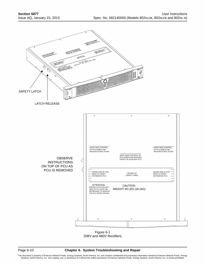
Section 5877 User Instructions Issue AQ, January 15, 2013 Spec. No. 582140000 (Models 802NLDB, 802NLEB and 802NL-B)
Page 6-10 Chapter 6. System Troubleshooting and Repair
This document is property of Emerson Network Power, Energy Systems, North America, Inc. and contains confidential and proprietary information owned by Emerson Network Power, Energy Systems, North America, Inc. Any copying, use, or disclosure of it without the written permission of Emerson Network Power, Energy Systems, North America, Inc. is strictly prohibited.
Figure 6-1 208V and 480V Rectifiers
SAFETY LATCH
LATCH RELEASE
OBSERVE
INSTRUCTIONS
ON TOP OF PCU AS
PCU IS REMOVED
MUST HAVE CONTROL
OF PCU WHEN LINEREACHES EDGE OF BAY
MUST HAVE CONTROL
OF PCU WHEN LINEREACHES EDGE OF BAY
MUST HAVE CONTROL OFPCU WHEN LINE REACHES
FRONT OF ADJACENT PCU
GRASP SIDE IN THISAREA TO CARRY
OR REMOVE PCU.
GRASP SIDE IN THISAREA TO CARRY
OR REMOVE PCU.
CENTER OF
GRAVITY AREA
SPRING LATCH ON LEFT
SIDE OF PCU MUST BE
DEPRESSED TO REMOVE
THE PCU FROM THE BAY.
CAUTION:
WEIGHT 40 LBS (18.1kG)
ATTENTION:
User Instructions Section 5877 Spec. No. 582140000 (Models 802NLDB, 802NLEB and 802NL-B) Issue AQ, January 15, 2013
Chapter 6. System Troubleshooting and Repair Page 6-11
This document is property of Emerson Network Power, Energy Systems, North America, Inc. and contains confidential and proprietary information owned by Emerson Network Power, Energy Systems, North America, Inc. Any copying, use, or disclosure of it without the written permission of Emerson Network Power, Energy Systems, North America, Inc. is strictly prohibited.
MCA Circuit Card Replacement
The MCA circuit card is installed in the Primary Power/Distribution Bay and Primary Power Only Bay. Router circuit cards are installed in the Secondary Power/Distribution Bays, Secondary Power Only Bays, and Distribution Only Bays.
Note: Refer to Figure 6-2 as this procedure is performed.
Procedure
1) Observe the admonishments presented at the beginning of this chapter, and those encountered in this procedure.
2) Performing this procedure may activate external alarms. Do one of the following. If possible, disable these alarms. If these alarms cannot be easily disabled, notify the appropriate personnel to disregard any future alarms associated with this system.
3) Replacing the MCA circuit card WILL result in all MCA settings being returned to their factory default values. In Table 6-2 and Table 6-3, either manually record all existing MCA settings or record the required settings for your site from your company's DC Plant Set Points specifications (standards).
Note: The MCA configuration can be saved by downloading the configuration using the LMS Monitoring System (if installed).
Refer to the MCA Menu Tree (Section 5886) and Chapter 2. Navigating the MCA to manually record MCA settings. The MCA Menu Tree is provided in the separate INSTALLATION MANUAL and the CD CARRIER MANUAL (it is also provided on the CD).
4) Open the bay's front door to access the MCA circuit card mounting position.
Warning: Damage to the MCA circuit card may result if the next step is not followed.
5) Connect an approved grounding strap to your wrist. Attach the other end to a suitable ground.
6) Remove fuse F3 that supplies input power to the MCA circuit card. Refer to Figure 6-7 for location.
7) With an external voltmeter, verify plant voltage is correct (MCA is powered down at this point).
8) Remove any network cables from the circuit card, noting their locations for re-assembly.
9) Remove the alarm cable connector TB1 from the circuit card. Note that terminal block TB1 consists of two pieces snapped together. The two pieces can be separated by first loosening the two screws; then gently pulling the one half from the other.
10) Loosen the circuit card retaining screw.
11) Remove the circuit card.
12) Set the switches of S1 on the replacement circuit card to match the settings of the removed circuit card.
13) Slide the replacement circuit card into its mounting location, ensuring the rear edge connector is firmly seated.
14) Secure the circuit card by tightening the circuit card retaining screw .
Section 5877 User Instructions Issue AQ, January 15, 2013 Spec. No. 582140000 (Models 802NLDB, 802NLEB and 802NL-B)
Page 6-12 Chapter 6. System Troubleshooting and Repair
This document is property of Emerson Network Power, Energy Systems, North America, Inc. and contains confidential and proprietary information owned by Emerson Network Power, Energy Systems, North America, Inc. Any copying, use, or disclosure of it without the written permission of Emerson Network Power, Energy Systems, North America, Inc. is strictly prohibited.
15) Replace fuse F3 which supplies input power to the MCA circuit card. Refer to Figure 6-7 for location.
16) The MCA goes through an initialization routine (as detailed in Chapter 5. Installing the Rectifiers and Initially Starting the System of the INSTALLATION INSTRUCTIONS [Section 5877]). During this initialization routine, check (and if required change) the MCA settings for your Site. In lieu of manually entering new MCA settings, if the old MCA configuration was downloaded via the LMS; upload the configuration. Refer to the LMS User Instructions for a procedure.
17) Remove the grounding wrist strap.
18) Close the bay's front door.
19) Enable the external alarms, or notify appropriate personnel that this procedure is finished.
20) Ensure that there are no local or remote alarms active on the system.

User Instructions Section 5877 Spec. No. 582140000 (Models 802NLDB, 802NLEB and 802NL-B) Issue AQ, January 15, 2013
Chapter 6. System Troubleshooting and Repair Page 6-13
This document is property of Emerson Network Power, Energy Systems, North America, Inc. and contains confidential and proprietary information owned by Emerson Network Power, Energy Systems, North America, Inc. Any copying, use, or disclosure of it without the written permission of Emerson Network Power, Energy Systems, North America, Inc. is strictly prohibited.
Setting Factory
Default Setting Required
Site Setting
Float Output Voltage 52.00V
Test/Equalize Output Voltage 52.00V
High Voltage Shutdown 57.50V
Rectifier Current Limit 100% of Rated
Full Load
High Voltage #1 Alarm 55.50V
High Voltage #2 Alarm 56.50V
Battery On Discharge Alarm 51.00V
Very Low Voltage Alarm 47.00V
Total Distribution Load Alarm 2000A
Distribution Group A Load Alarm
2000A
Distribution Group B Load Alarm
2000A
High Battery Ambient Temperature #1 Alarm
Off
High Battery Ambient Temperature #2 Alarm
Off
Low Battery Ambient Temperature #1 Alarm
Off
Low Battery Ambient Temperature #2 Alarm
Off
Digital Temperature Compensation (Slope)
Off
(0V/ C)
Digital Temperature Compensation (Maximum Compensation)
56.50V
Digital Temperature Compensation (Minimum Compensation)
50.00V
Table 6-2 MCA Basic Settings
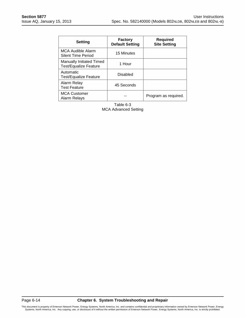
Section 5877 User Instructions Issue AQ, January 15, 2013 Spec. No. 582140000 (Models 802NLDB, 802NLEB and 802NL-B)
Page 6-14 Chapter 6. System Troubleshooting and Repair
This document is property of Emerson Network Power, Energy Systems, North America, Inc. and contains confidential and proprietary information owned by Emerson Network Power, Energy Systems, North America, Inc. Any copying, use, or disclosure of it without the written permission of Emerson Network Power, Energy Systems, North America, Inc. is strictly prohibited.
Setting Factory
Default Setting Required
Site Setting
MCA Audible Alarm Silent Time Period
15 Minutes
Manually Initiated Timed Test/Equalize Feature
1 Hour
Automatic Test/Equalize Feature
Disabled
Alarm Relay Test Feature
45 Seconds
MCA Customer Alarm Relays
-- Program as required.
Table 6-3 MCA Advanced Setting

User Instructions Section 5877 Spec. No. 582140000 (Models 802NLDB, 802NLEB and 802NL-B) Issue AQ, January 15, 2013
Chapter 6. System Troubleshooting and Repair Page 6-15
This document is property of Emerson Network Power, Energy Systems, North America, Inc. and contains confidential and proprietary information owned by Emerson Network Power, Energy Systems, North America, Inc. Any copying, use, or disclosure of it without the written permission of Emerson Network Power, Energy Systems, North America, Inc. is strictly prohibited.
Router Circuit Card Replacement
The MCA circuit card is installed in the Primary Power/Distribution Bay and Primary Power Only Bay. Router circuit cards are installed in the Secondary Power/Distribution Bays, Secondary Power Only Bays, and Distribution Only Bays.
Note: Refer to Figure 6-2 and Figure 6-3 as this procedure is performed.
Procedure
1) Observe the admonishments presented at the beginning of this chapter, and those encountered in this procedure.
2) Performing this procedure may activate external alarms. Do one of the following. If possible, disable these alarms. If these alarms cannot be easily disabled, notify the appropriate personnel to disregard any future alarms associated with this system.
3) Open the bay's front door to access the Router circuit card mounting position.
Warning: Damage to the Router circuit card may result if the next step is not followed.
4) Connect an approved grounding strap to your wrist. Attach the other end to a suitable ground.
5) Remove the fuse which supplies input power to the Router circuit card. Refer to Figure 6-7 and Figure 6-8 for location.
6) Remove any network cables from the circuit card, noting their locations for re-assembly.
7) Loosen the circuit card retaining screw.
8) Remove the circuit card.
9) Slide the replacement circuit card into its mounting location, ensuring the rear edge connector is firmly seated.
10) Secure the circuit card by tightening the circuit card retaining screw.
11) Replace the fuse which supplies input power to the Router circuit card. Refer to Figure 6-7 and Figure 6-8 for location.
12) Remove the grounding wrist strap.
13) Close the bay's front door.
14) Enable the external alarms, or notify appropriate personnel that this procedure is finished.
15) Ensure that there are no local or remote alarms active on the system.
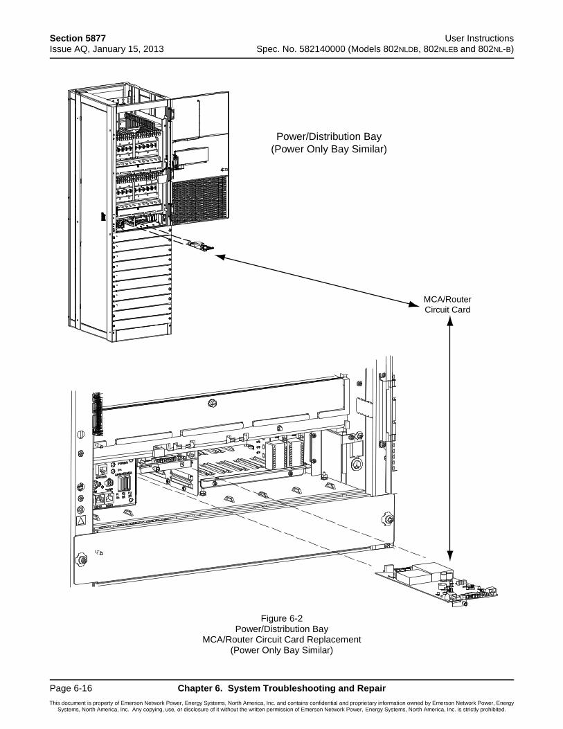
Section 5877 User Instructions Issue AQ, January 15, 2013 Spec. No. 582140000 (Models 802NLDB, 802NLEB and 802NL-B)
Page 6-16 Chapter 6. System Troubleshooting and Repair
This document is property of Emerson Network Power, Energy Systems, North America, Inc. and contains confidential and proprietary information owned by Emerson Network Power, Energy Systems, North America, Inc. Any copying, use, or disclosure of it without the written permission of Emerson Network Power, Energy Systems, North America, Inc. is strictly prohibited.
Figure 6-2 Power/Distribution Bay
MCA/Router Circuit Card Replacement (Power Only Bay Similar)
Power/Distribution Bay
(Power Only Bay Similar)
MCA/Router
Circuit Card
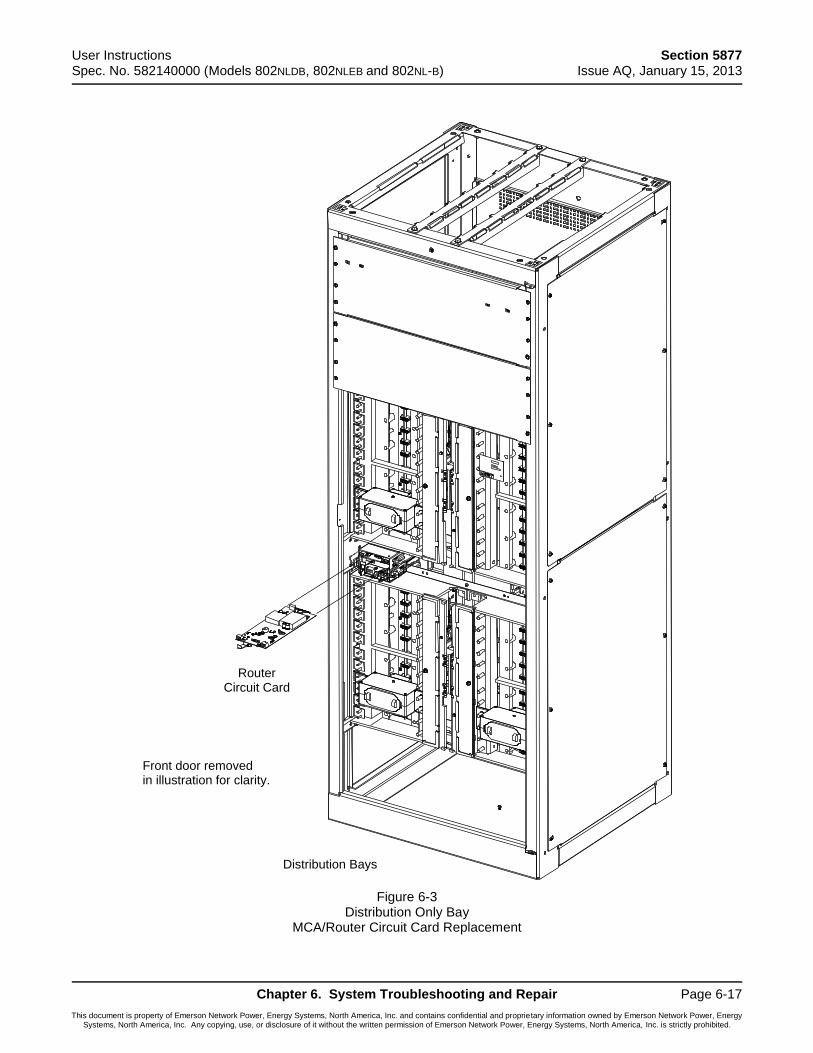
User Instructions Section 5877 Spec. No. 582140000 (Models 802NLDB, 802NLEB and 802NL-B) Issue AQ, January 15, 2013
Chapter 6. System Troubleshooting and Repair Page 6-17
This document is property of Emerson Network Power, Energy Systems, North America, Inc. and contains confidential and proprietary information owned by Emerson Network Power, Energy Systems, North America, Inc. Any copying, use, or disclosure of it without the written permission of Emerson Network Power, Energy Systems, North America, Inc. is strictly prohibited.
Figure 6-3 Distribution Only Bay
MCA/Router Circuit Card Replacement
RouterCircuit Card
Distribution Bays
Front door removedin illustration for clarity.
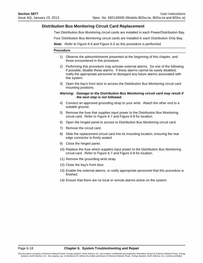
Section 5877 User Instructions Issue AQ, January 15, 2013 Spec. No. 582140000 (Models 802NLDB, 802NLEB and 802NL-B)
Page 6-18 Chapter 6. System Troubleshooting and Repair
This document is property of Emerson Network Power, Energy Systems, North America, Inc. and contains confidential and proprietary information owned by Emerson Network Power, Energy Systems, North America, Inc. Any copying, use, or disclosure of it without the written permission of Emerson Network Power, Energy Systems, North America, Inc. is strictly prohibited.
Distribution Bus Monitoring Circuit Card Replacement
Two Distribution Bus Monitoring circuit cards are installed in each Power/Distribution Bay.
Four Distribution Bus Monitoring circuit cards are installed in each Distribution Only Bay.
Note: Refer to Figure 6-4 and Figure 6-5 as this procedure is performed.
Procedure
1) Observe the admonishments presented at the beginning of this chapter, and those encountered in this procedure.
2) Performing this procedure may activate external alarms. Do one of the following. If possible, disable these alarms. If these alarms cannot be easily disabled, notify the appropriate personnel to disregard any future alarms associated with this system.
3) Open the bay's front door to access the Distribution Bus Monitoring circuit card mounting positions.
Warning: Damage to the Distribution Bus Monitoring circuit card may result if the next step is not followed.
4) Connect an approved grounding strap to your wrist. Attach the other end to a suitable ground.
5) Remove the fuse that supplies input power to the Distribution Bus Monitoring circuit card. Refer to Figure 6-7 and Figure 6-8 for location.
6) Open the hinged panel to access to Distribution Bus Monitoring circuit card.
7) Remove the circuit card.
8) Slide the replacement circuit card into its mounting location, ensuring the rear edge connector is firmly seated.
9) Close the hinged panel.
10) Replace the fuse which supplies input power to the Distribution Bus Monitoring circuit card. Refer to Figure 6-7 and Figure 6-8 for location.
11) Remove the grounding wrist strap.
12) Close the bay's front door.
13) Enable the external alarms, or notify appropriate personnel that this procedure is finished.
14) Ensure that there are no local or remote alarms active on the system.
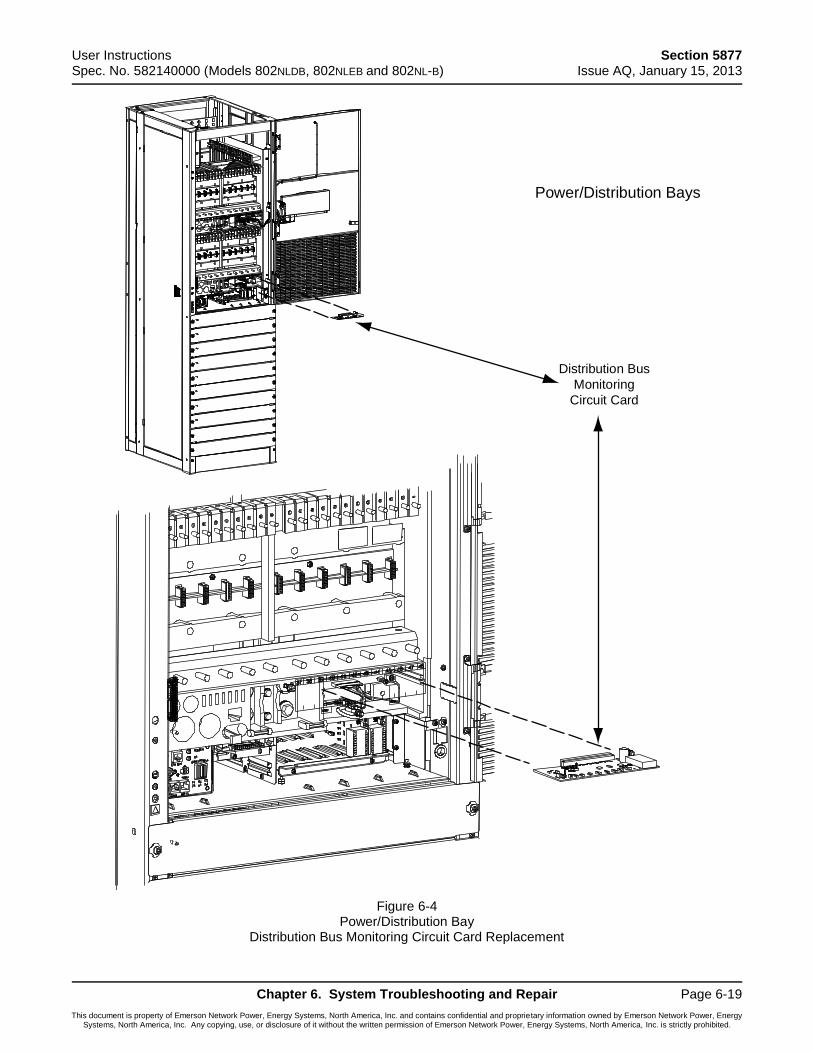
User Instructions Section 5877 Spec. No. 582140000 (Models 802NLDB, 802NLEB and 802NL-B) Issue AQ, January 15, 2013
Chapter 6. System Troubleshooting and Repair Page 6-19
This document is property of Emerson Network Power, Energy Systems, North America, Inc. and contains confidential and proprietary information owned by Emerson Network Power, Energy Systems, North America, Inc. Any copying, use, or disclosure of it without the written permission of Emerson Network Power, Energy Systems, North America, Inc. is strictly prohibited.
Figure 6-4 Power/Distribution Bay
Distribution Bus Monitoring Circuit Card Replacement
Power/Distribution Bays
Distribution Bus
Monitoring
Circuit Card
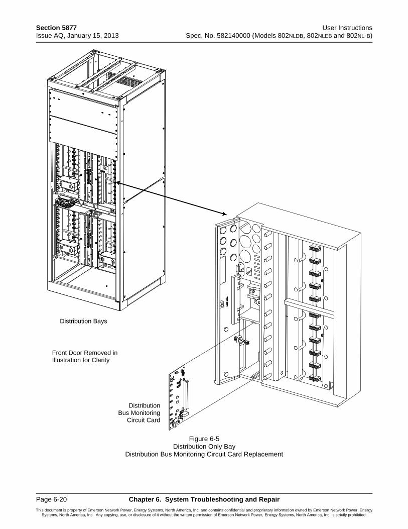
Section 5877 User Instructions Issue AQ, January 15, 2013 Spec. No. 582140000 (Models 802NLDB, 802NLEB and 802NL-B)
Page 6-20 Chapter 6. System Troubleshooting and Repair
This document is property of Emerson Network Power, Energy Systems, North America, Inc. and contains confidential and proprietary information owned by Emerson Network Power, Energy Systems, North America, Inc. Any copying, use, or disclosure of it without the written permission of Emerson Network Power, Energy Systems, North America, Inc. is strictly prohibited.
Figure 6-5 Distribution Only Bay
Distribution Bus Monitoring Circuit Card Replacement
Distribution Bays
Front Door Removed inIllustration for Clarity
DistributionBus Monitoring
Circuit Card
User Instructions Section 5877 Spec. No. 582140000 (Models 802NLDB, 802NLEB and 802NL-B) Issue AQ, January 15, 2013
Chapter 6. System Troubleshooting and Repair Page 6-21
This document is property of Emerson Network Power, Energy Systems, North America, Inc. and contains confidential and proprietary information owned by Emerson Network Power, Energy Systems, North America, Inc. Any copying, use, or disclosure of it without the written permission of Emerson Network Power, Energy Systems, North America, Inc. is strictly prohibited.
MCA Customer Alarm Relay Circuit Card Replacement
Refer to the Installation Procedure detailed in the Installation Instructions (Section 5876).
MCA I/O Circuit Card Replacement
Refer to the Installation Procedure detailed in the Installation Instructions (Section 5876).
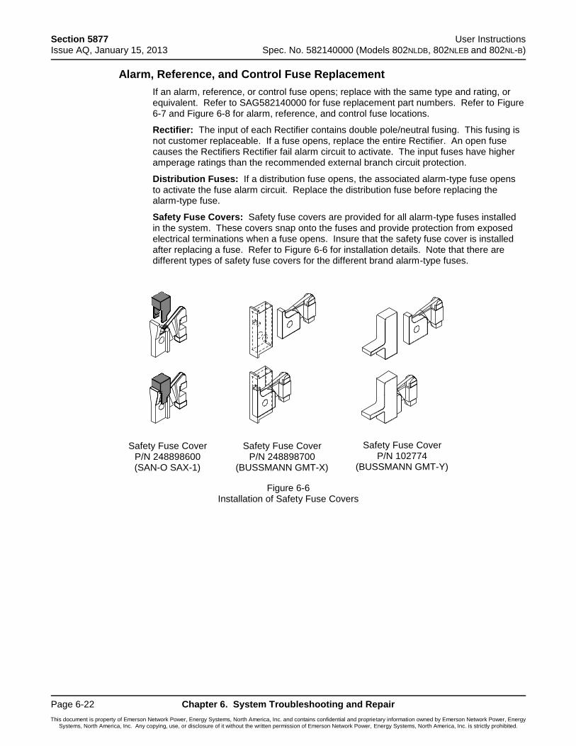
Section 5877 User Instructions Issue AQ, January 15, 2013 Spec. No. 582140000 (Models 802NLDB, 802NLEB and 802NL-B)
Page 6-22 Chapter 6. System Troubleshooting and Repair
This document is property of Emerson Network Power, Energy Systems, North America, Inc. and contains confidential and proprietary information owned by Emerson Network Power, Energy Systems, North America, Inc. Any copying, use, or disclosure of it without the written permission of Emerson Network Power, Energy Systems, North America, Inc. is strictly prohibited.
Alarm, Reference, and Control Fuse Replacement
If an alarm, reference, or control fuse opens; replace with the same type and rating, or equivalent. Refer to SAG582140000 for fuse replacement part numbers. Refer to Figure 6-7 and Figure 6-8 for alarm, reference, and control fuse locations.
Rectifier: The input of each Rectifier contains double pole/neutral fusing. This fusing is not customer replaceable. If a fuse opens, replace the entire Rectifier. An open fuse causes the Rectifiers Rectifier fail alarm circuit to activate. The input fuses have higher amperage ratings than the recommended external branch circuit protection.
Distribution Fuses: If a distribution fuse opens, the associated alarm-type fuse opens to activate the fuse alarm circuit. Replace the distribution fuse before replacing the alarm-type fuse.
Safety Fuse Covers: Safety fuse covers are provided for all alarm-type fuses installed in the system. These covers snap onto the fuses and provide protection from exposed electrical terminations when a fuse opens. Insure that the safety fuse cover is installed after replacing a fuse. Refer to Figure 6-6 for installation details. Note that there are different types of safety fuse covers for the different brand alarm-type fuses.
Figure 6-6 Installation of Safety Fuse Covers
Safety Fuse CoverP/N 248898600(SAN-O SAX-1)
Safety Fuse CoverP/N 248898700
(BUSSMANN GMT-X)
Safety Fuse CoverP/N 102774
(BUSSMANN GMT-Y)
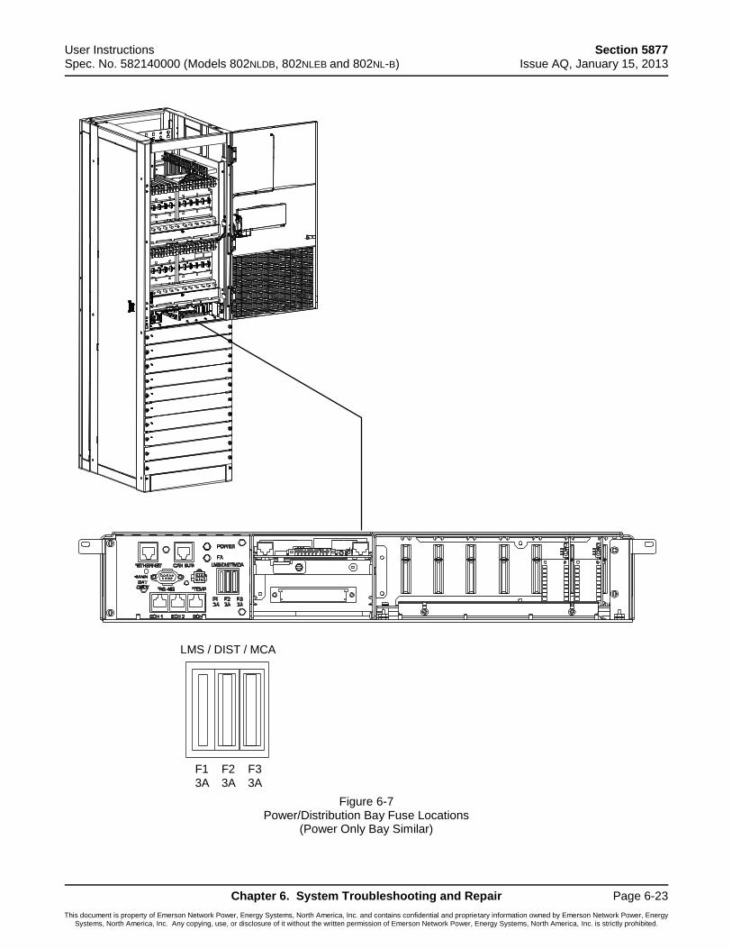
User Instructions Section 5877 Spec. No. 582140000 (Models 802NLDB, 802NLEB and 802NL-B) Issue AQ, January 15, 2013
Chapter 6. System Troubleshooting and Repair Page 6-23
This document is property of Emerson Network Power, Energy Systems, North America, Inc. and contains confidential and proprietary information owned by Emerson Network Power, Energy Systems, North America, Inc. Any copying, use, or disclosure of it without the written permission of Emerson Network Power, Energy Systems, North America, Inc. is strictly prohibited.
Figure 6-7 Power/Distribution Bay Fuse Locations
(Power Only Bay Similar)
LMS / DIST / MCA
F1 F2 F3
3A 3A 3A
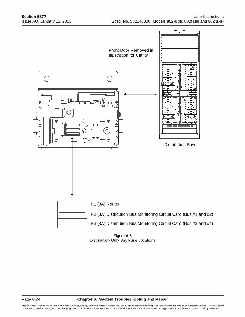
Section 5877 User Instructions Issue AQ, January 15, 2013 Spec. No. 582140000 (Models 802NLDB, 802NLEB and 802NL-B)
Page 6-24 Chapter 6. System Troubleshooting and Repair
This document is property of Emerson Network Power, Energy Systems, North America, Inc. and contains confidential and proprietary information owned by Emerson Network Power, Energy Systems, North America, Inc. Any copying, use, or disclosure of it without the written permission of Emerson Network Power, Energy Systems, North America, Inc. is strictly prohibited.
Figure 6-8 Distribution Only Bay Fuse Locations
Distribution Bays
Front Door Removed inIllustration for Clarity
F1 (3A) Router
F2 (3A) Distribution Bus Monitoring Circuit Card (Bus #1 and #2)
F3 (3A) Distribution Bus Monitoring Circuit Card (Bus #3 and #4)
User Instructions Section 5877 Spec. No. 582140000 (Models 802NLDB, 802NLEB and 802NL-B) Issue AQ, January 15, 2013
Chapter 6. System Troubleshooting and Repair Page 6-25
This document is property of Emerson Network Power, Energy Systems, North America, Inc. and contains confidential and proprietary information owned by Emerson Network Power, Energy Systems, North America, Inc. Any copying, use, or disclosure of it without the written permission of Emerson Network Power, Energy Systems, North America, Inc. is strictly prohibited.
Rectifier Fan Replacement
The rectifier fans are not field-replaceable. If a fan fails, replace the rectifier as described in this chapter.
Caution: In a system with NO redundant Rectifier Module, battery must have sufficient reserve to power the load(s) while the Rectifier Module is removed.

Section 5877 User Instructions Issue AQ, January 15, 2013 Spec. No. 582140000 (Models 802NLDB, 802NLEB and 802NL-B)
Page 6-26 Chapter 6. System Troubleshooting and Repair
This document is property of Emerson Network Power, Energy Systems, North America, Inc. and contains confidential and proprietary information owned by Emerson Network Power, Energy Systems, North America, Inc. Any copying, use, or disclosure of it without the written permission of Emerson Network Power, Energy Systems, North America, Inc. is strictly prohibited.
ADDING A BATTERY CHARGE DIGITAL TEMPERATURE COMPENSATION PROBE TO A PREVIOUSLY OPERATED SYSTEM
This procedure details the steps to add a Battery Charge Digital Temperature Compensation Probe to a system that has been previously started, configured, and checked.
Procedure
1) Refer to the separate Installation Manual, “Chapter 3. Making Electrical Connections”, and mount the Battery Charge Digital Temperature Compensation Probe near the batteries.
2) Refer to the separate Installation Manual, “Chapter 3. Making Electrical Connections”, and connect the Battery Charge Digital Temperature Compensation Probe to the system. The MCA automatically detects the probe and adds it to the inventory without any alarms. The default slope setting is NO TEMPERATURE COMPENSATION.
3) Refer to “Chapter 4. MCA System Adjustments” of these instructions, and set the following digital battery charge temperature compensation parameters: SLOPE, MAXIMUM COMPENSATION, and MINIMUM COMPENSATION.
4) Refer to “Chapter 4. MCA System Adjustments” of these instructions, and set the following alarm parameters: HIGH TEMPERATURE #1 ALARM, HIGH TEMPERATURE #2 ALARM, LOW TEMPERATURE #1 ALARM, and LOW TEMPERATURE #2 ALARM.
5) Verify that battery charge temperature compensation has begun by comparing the SYSTEM voltage reading versus the FLOAT setting. Depending on the battery ambient temperature, the SYSTEM voltage should be higher or lower than the FLOAT setting by the amount of slope V/ºC (note that SYSTEM voltage will also vary from the FLOAT setpoint depending on the load).
Note: At 25ºC, the battery charge temperature compensated SYSTEM voltage equals the FLOAT voltage setting.
Note: If the probe is disconnected or fails, a major alarm (local and extended) activates and the system returns to the FLOAT voltage setting.
User Instructions Section 5877 Spec. No. 582140000 (Models 802NLDB, 802NLEB and 802NL-B) Issue AQ, January 15, 2013
Chapter 6. System Troubleshooting and Repair Page 6-27
This document is property of Emerson Network Power, Energy Systems, North America, Inc. and contains confidential and proprietary information owned by Emerson Network Power, Energy Systems, North America, Inc. Any copying, use, or disclosure of it without the written permission of Emerson Network Power, Energy Systems, North America, Inc. is strictly prohibited.
REMOVING A BATTERY CHARGE DIGITAL TEMPERATURE COMPENSATION PROBE FROM A PREVIOUSLY OPERATED SYSTEM
This procedure details the steps to remove a Battery Charge Digital Temperature Compensation Probe from a system that has been previously started, configured, and checked.
Procedure
1) In the Configure Menu, set the SLOPE = 0.vvvV C/F to NO TEMPERATURE COMPENSATION. Temperature Compensation stops and the System returns to the FLOAT voltage setting.
2) Remove the probe. The Major Alarm activates. Update inventory to clear this alarm, as described in this chapter.
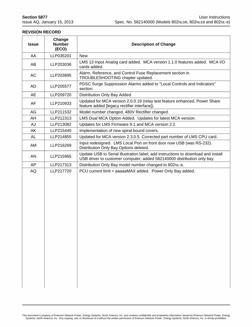
Section 5877 User Instructions Issue AQ, January 15, 2013 Spec. No. 582140000 (Models 802NLDB, 802NLEB and 802NL-B)
This document is property of Emerson Network Power, Energy Systems, North America, Inc. and contains confidential and proprietary information owned by Emerson Network Power, Energy Systems, North America, Inc. Any copying, use, or disclosure of it without the written permission of Emerson Network Power, Energy Systems, North America, Inc. is strictly prohibited.
REVISION RECORD
Issue Change Number (ECO)
Description of Change
AA LLP035201 New
AB LLP203036 LMS 12-Input Analog card added. MCA version 1.1.0 features added. MCA I/O cards added.
AC LLP203895 Alarm, Reference, and Control Fuse Replacement section in TROUBLESHOOTING chapter updated.
AD LLP205577 PDSC Surge Suppression Alarms added to "Local Controls and Indicators" section.
AE LLP209720 Distribution Only Bay Added.
AF LLP210933 Updated for MCA version 2.0.0.19 (relay test feature enhanced, Power Share feature added [legacy rectifier interface]).
AG LLP211532 Model number changed, 480V Rectifier changed.
AH LLP212313 LMS Dual MCA Option Added. Updates for latest MCA version.
AJ LLP213082 Updates for LMS Firmware 9.1 and MCA version 2.2.
AK LLP215440 Implementation of new spiral bound covers.
AL LLP214855 Updated for MCA version 2.3.0.5. Corrected part number of LMS CPU card.
AM LLP216269 Input redesigned. LMS Local Port on front door now USB (was RS-232). Distribution Only Bay Options deleted.
AN LLP215965 Update USB to Serial illustration label; add instructions to download and install USB driver to customer computer; added 582140000 distribution only bay.
AP LLP217313 Distribution Only Bay model number changed to 802NL-B.
AQ LLP217720 PCU current limit = aaaaaMAX added. Power Only Bay added.
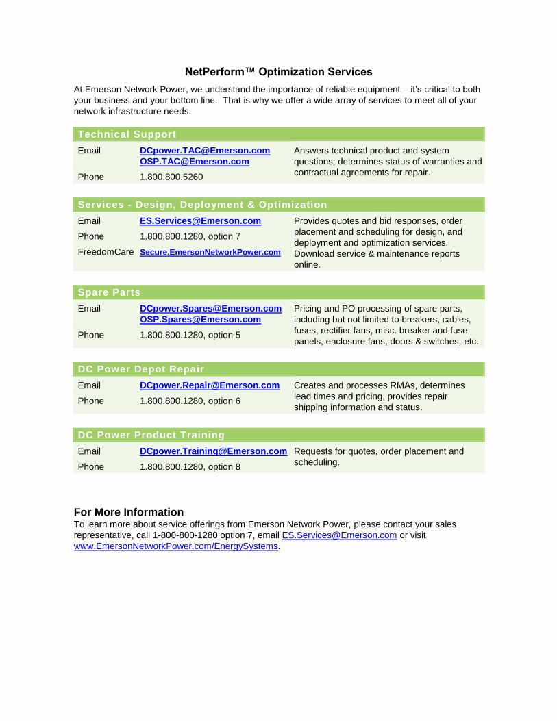
NetPerform™ Optimization Services
At Emerson Network Power, we understand the importance of reliable equipment – it’s critical to both
your business and your bottom line. That is why we offer a wide array of services to meet all of your
network infrastructure needs.
Technical Support
Email [email protected]
Answers technical product and system
questions; determines status of warranties and
contractual agreements for repair. Phone 1.800.800.5260
Services - Design, Deployment & Optimization
Email [email protected] Provides quotes and bid responses, order
placement and scheduling for design, and
deployment and optimization services.
Download service & maintenance reports
online.
Phone 1.800.800.1280, option 7
FreedomCare Secure.EmersonNetworkPower.com
Spare Parts
Email [email protected]
Pricing and PO processing of spare parts,
including but not limited to breakers, cables,
fuses, rectifier fans, misc. breaker and fuse
panels, enclosure fans, doors & switches, etc. Phone 1.800.800.1280, option 5
DC Power Depot Repair
Email [email protected] Creates and processes RMAs, determines
lead times and pricing, provides repair
shipping information and status. Phone 1.800.800.1280, option 6
DC Power Product Training
Email [email protected] Requests for quotes, order placement and
scheduling. Phone 1.800.800.1280, option 8
For More Information To learn more about service offerings from Emerson Network Power, please contact your sales
representative, call 1-800-800-1280 option 7, email [email protected] or visit
www.EmersonNetworkPower.com/EnergySystems.