Embed Size (px)
Citation preview
������������������� ������� �����
Version 4.0 P/N 093-0576-000 Rev.E
Copyright Notice
NetScreen, NetScreen Technologies, GigaScreen, and the NetScreen logo are registered trademarks of NetScreen Technologies, Inc. NetScreen-5XP, NetScreen-5XT, NetScreen-25, NetScreen-50, NetScreen-100, NetScreen-204, NetScreen-208, NetScreen-500, NetScreen-1000, NetScreen-5200, NetScreen-5400, NetScreen-Global PRO, NetScreen-Global PRO Express, NetScreen-Remote Security Client, NetScreen-Remote VPN Client, NetScreen-IDP 100, NetScreen-IDP 500, GigaScreen ASIC, GigaScreen-II ASIC, and NetScreen ScreenOS are trademarks of NetScreen Technologies, Inc. All other trademarks and registered trademarks are the property of their respective companies.Information in this document is subject to change without notice.
No part of this document may be reproduced or transmitted in any form or by any means, electronic or mechanical, for any purpose, without receiving written permission from
NetScreen Technologies, Inc. 350 Oakmead ParkwaySunnyvale, CA 94085 U.S.A.www.netscreen.com
FCC Statement
The following information is for FCC compliance of Class A devices: This equipment has been tested and found to comply with the limits for a Class A digital device, pursuant to part 15 of the FCC rules. These limits are designed to provide reasonable protection against harmful interference when the equipment is operated in a commercial environment. The equipment generates, uses, and can radiate radio-frequency energy and, if not installed and used in accordance with the instruction manual, may cause harmful interference to radio communications. Operation of this equipment in a residential area is likely to cause harmful interference, in which case users will be required to correct the interference at their own expense.
The following information is for FCC compliance of Class B devices: The equipment described in this manual generates and
may radiate radio-frequency energy. If it is not installed in accordance with NetScreen’s installation instructions, it may cause interference with Radio and television reception. This equipment has been tested and found to comply with the limits for a Class B digital devices in accordance with the specifications in part 15 of the FCC rules. These specifications are designed to provide reasonable protection against such interference in a residential installation. However, there is no guarantee that interference will not occur in a particular installation.
If this equipment does cause harmful interference to radio or television reception, which can be determined by turning the equipment off and on, the user is encouraged to try to correct the interference by one or more of the following measures:
• Reorient or relocate the receiving antenna.
• Increase the separation between the equipment and receiver.
• Consult the dealer or an experienced radio/TV technician for help.
• Connect the equipment to an outlet on a circuit different from that to which the receiver is connected.
Caution: Changes or modifications to this product could void the user's warranty and authority to operate this device.
Disclaimer
THE SOFTWARE LICENSE AND LIMITED WARRANTY FOR THE ACCOMPANYING PRODUCT ARE SET FORTH IN THE INFORMATION PACKET THAT SHIPPED WITH THE PRODUCT AND ARE INCORPORATED HEREIN BY THIS REFERENCE. IF YOU ARE UNABLE TO LOCATE THE SOFTWARE LICENSE OR LIMITED WARRANTY, CONTACT YOUR NETSCREEN REPRESENTATIVE FOR A COPY.
���������������������������������������������������������������������������������������������������������������������������������������������������������������������
�� ������� ��� �� ���������������������������������������������������������������������������������������������������
�������� ����������������������� ������������������������������������������������������������������������������ ����� ��������������������������������������������������������������������������������� ���� ���� ���� ����������������������������������������������������������������������������������������� � ������������ ���� ���� ������������������������������������������������������������������� �
����������!"���#������������������������������������������������������������������������������������ � $�%������"$�� � ���� ����������������������������������������������������������������������������� �����$�%������ ��������������������������������������������������������������������������������� &�� ��� � �"����������������'�����������������������������������������������������
��!��������� ��� ��� �������������������������������������������������������������������������������������������� #
(�)�����*����������� �� ���������������������������������������������������������������������������������� #
����� �) ������������������������������������������������������������������������������������������������������������������������������������������ +
��!�����,-..!"��������������������������������������������������������������������������������������������������-�/� ��!�����,-.0$�� ��������������������������������������������������������������������������������- ��!�����,-.1$�� �� ������������������������������������������������������������������������������������-
�/�'��������� ���������������������������������������������������������������������������������������������������������2!"����!������3$$ �%��" ��������������������������������������������������������������������������������2&����4������"� �/���������������������������������������������������������������������������������������5����������*���������������������������������������������������������������������������������������5���%���'���/����!��� ��������������������������������������������������������������������������������53�/����������������������������������������������������������������������������������������������������������6
�/�4������������������������������������������������������������������������������������������������������������������6��)��!�%%� �� ������������������������������������������������������������������������������������������������6��)��'��� ������������������������������������������������������������������������������������������������������7
������� ���/�$�� ��������������������������������������������������������������������������������������������������������������������������� 8
���������������� ���� ��� ����������������������������������������������������������������������������������+.
������� ��39� %����,4��:��������� �� �����������������������������������������������������������������+.39� %����4��:��������� ���� ��� ��� ��������������������������������������������������������+.4��:,*���� ���/�$�� ������������������������������������������������������������������������������++
������� ���/���)�� ��������������������������������������������������������������������������������������������++
; � ���$���)��!�%%�" ��������������������������������������������������������������������������������������+-
������� ���/� ��!�����,-..$�� ������/��$�� ��� ��������������������������������������+2
������������ ��
���������������
���� ��� ���/�$�� �� ������������������������������������������������������������������������������������������������������������������ +5
�%���� ����*���� ������������������������������������������������������������������������������������������������+6�����%�����*��� �����������������������������������������������������������������������������������������+64����*������������������������������������������������������������������������������������������������������+6
�/� ��!�����,-..�������������������������������������������������������������������������������������������+7
������� ���/�$�� �����! ����!���� �"����)�" �������������������������������������������+1������� � �"3#��%��� ����������������������������������������������������������������������������������+1������� ��$�� ��������� �� ���������������������������������������������������������������������+8
3����� �/ ����(&������� ��<��)���$�� ������������������������������������������������������-.
������� ���� � ��������� ��������� ����� �� ���������������������������������������������������--3����� �/ ������� ���3�������������� ��������������������������������������������������--�/��� ��=������ � ����������)������������������������������������������������������-2!��� ��������������������&�������� ���������������������������������������������������������-2� �) ������������������!��� ��� ������������������������������������������������������������-2!��� ���/���&���������/�*������������������ �������������������������������-2!��� ���/���&����������/�>������?������������ ���������������������������������-0&���) ��������������� ��������������������������������������������������������������������������-0�/��� ��=������ � ����������)��� ����������������������������������������������-5
���� ��� ���/�$�� ��������������;��>�!��� ����������������������������������������������-5!���� ����������!��� ��>� �������� ���������������������������������������������������������-5!���� ����������!��� ��>� ��$ ���% ��������������������������������������������������������-63����� �/ ����>�*���������!��� ���������������������������������������������������������-6
4����� ���/�$�� ����'�����"$������!��� ��� ����������������������������������������������������-7>� ���������������4�����/�$�� �� ����������������������������������������������������-7>� ���/�&����4������"� �/�����4�����/�$�� �� ����������������������������������-1
!%�� � ��� ��� ��������������������������������������������������������������������������������������������������������������������������������&,+
��!�����,-..&��� ����� ������������������������������������������������������������������������������������������-
3����� ���!%�� � ��� �� ���������������������������������������������������������������������������������������������-
3�� ��������� �����������������������������������������������������������������������������������������������������������-
3<!���� � ��� ��� ����������������������������������������������������������������������������������������������������-
!����"���� � ��� ��� ��������������������������������������������������������������������������������������������������-
3*����� � ��� ��� ������������������������������������������������������������������������������������������������������-
���� ����� ������������� ��� �@3&�-�������������������������������������������������������������������������������������� <,+
���%���"����� �" ���/� ��!�����$�� ������������� ��� �3&�-���%� ���� +
���%��!��%���!������ ��!�����$�� ������������� ��� �3&�-���%� ������������������������������������������������������������������������-
!���� ��@!��%% ��@���4�� �) ��&�� ����� ����������������������������������������������������������5
����# ������������������������������������������������������������������������������������������������������������������ +,
� ��!�����,-..!�� ��
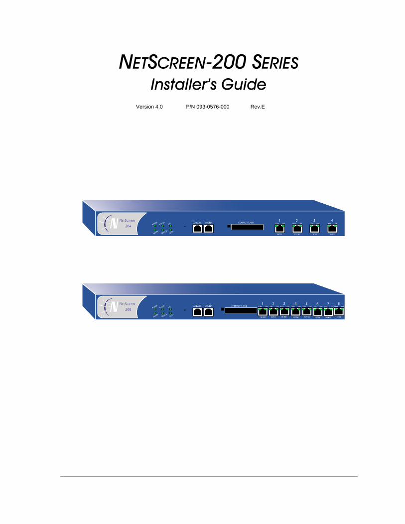
�������The NetScreen-200 Series consists of versatile, purpose-built, high-performance security systems that provide IPSec VPN and firewall services for medium and large enterprise offices, e-business sites, data centers, and carrier infrastructures.
The NetScreen-200 Series includes the following device models:
• The NetScreen-204, which has four 10/100 BaseT interface ports and performs firewall functions at 400 Mbps
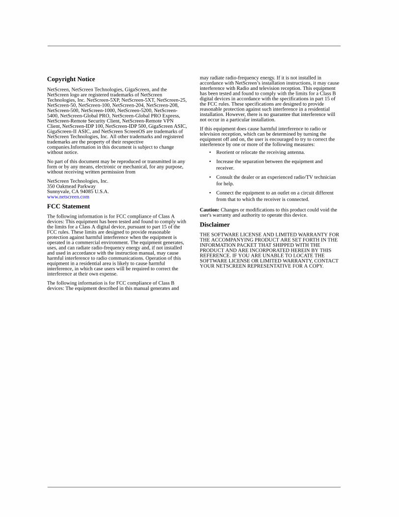
• The NetScreen-208, which has eight 10/100 BaseT interface ports and performs firewall functions at 550 Mbps
All NetScreen-200 Series 10/100 BaseT ports perform auto-speed sensing and auto-polarity correction.
���� ������� �This manual has three chapters and two appendices.
Chapter 1, "Overview" provides a detailed overview of the system and its components.
Chapter 2, "Installing the Device" describes how to rack-mount the NetScreen-200 systems and connect the systems to other devices.
Chapter 3, "Configuring the Device" details how to connect the NetScreen-200 device to the network and perform initial configuration.
Appendix A, "Specifications" provides a list of physical specifications about the NetScreen-200 Series, the modules, and power supplies.
Appendix B, "Configuration for Common Criteria, EAL2" provides information about configuring NetScreen devices for Common Criteria, EAL2 compliance.
� ������������������������ ����� ��Some of the instructions and examples provided in this manual contain CLI commands, most of which perform initial configuration of the NetScreen-200 device. The command examples use conventions for variables and syntax.
������������� �����Most NetScreen CLI commands have changeable parameters that affect the outcome of command execution. NetScreen documention represents these parameters as variables. Such variables may include names, identification numbers, IP addresses, subnet masks, numbers, dates, and other values.
������������ �� �
�������
��� ���� ���� ��The variable notation used in this manual consists of italicized parameter identifiers. For example, the set arp command uses four identifiers, as shown here:
set arp{ip_addr mac_addr interfaceage number |always-on-dest |no-cache}
where
• ip_addr represents an IP address.• mac_addr represents a MAC address.• interface represents a physical or logical interface.• number represents a numerical value.
Thus, the command might take the following form:
ns-> set arp 172.16.10.11 00e02c000080 ethernet2
where 172.16.10.11 is an IP address, 00e02c000080 is a MAC address, and ethernet2 is a physical interface.
������������ ���� ����The following list shows the CLI variable names used in NetScreen documents.
comm_name The community name of a host or other device.
date_str A date value.
dev_name A device name, as with flash card memory.
dom_name A domain name, such as “acme” in www.acme.com.
dst_addr A destination address, as with a policy definition that defines a source and destination IP address.
filename The name of a file.
grp_name The name of a group, such as an address group or service group.
interface A physical or logical interface.
id_num An identification number.
ip_addr An IP address.
key_str A key, such as a session key, a private key, or a public key.
key_hex A key expressed as a hexadecimal number.
loc_str A location of a file or other resource.
mac_addr A MAC address.
� ������������ ��
�������� ����������������������� ���
Some commands contain multiple variables of the same type. The names of such variables may be numbered to identify each individually. For example, the set dip command contains two id_num variables, each numbered for easy identification:
set dip group id_num1 [ member id_num2 ]
����������!"���#Each CLI command description in this manual reveals some aspect of command syntax. This syntax may include options, switches, parameters, and other features. To illustrate syntax rules, some command descriptions use dependency delimiters. Such delimiters indicate which command features are mandatory, and in which contexts.
mbr_name The name of a member in a group, such as an address group or a service group.
mask A subnet mask, such as 255.255.255.224 or /24.
name_str The name of an item, such as an address book entry.
number A numeric value, usually an integer, such as a threshold or a maximum.
pol_num A policy number.
port_num A number identifying a logical port.
pswd_str A password.
ptcl_num A number uniquely identifying a protocol, such as TCP, IP, or UDP.
serv_name The name of a server.
shar_secret A shared secret value.
spi_num A Security Parameters Index (SPI) number.
src_addr A source address, as with a policy definition that defines a source and destination IP address.
string A character string, such as a comment.
svc_name The name of a service, such at HTTP or MAIL.
time_str A time value.
tunn_str The name of a tunnel, such as an L2TP tunnel.
url_str A URL, such as www.acme.com.
usr_str A user, usually an external entity such as a dialup user.
vrouter A local virtual router, such as trust-vr or untrust-vr.
zone The name of a security zone.
��!�����,-..!�� �� �
�������
$�%������"$�� � ����Each syntax description shows the dependencies between command features by using special characters.
• The { and } symbols denote a mandatory feature. Features enclosed by these symbols are essential for execution of the command.
• The [ and ] symbols denote an optional feature. Features enclosed by these symbols are not essential for execution of the command, although omitting such features might adversely affect the outcome.
• The | symbol denotes an “or” relationship between two features. When this symbol appears between two features on the same line, you can use either feature (but not both). When this symbol appears at the end of a line, you can use the feature on that line, or the one below it.
�����$�%������ ��Many CLI commands have nested dependencies, which make features optional in some contexts, and mandatory in others. The three hypothetical features shown below demonstrate this principle.
[ feature_1 { feature_2 | feature_3 } ]
In this example, the delimiters [ and ] surround the entire clause. Consequently, you can omit feature_1, feature_2, and feature_3, and still execute the command successfully. However, because the { and } delimiters surround feature_2 and feature_3, you must include either feature_2 or feature_3 if you include feature_1. Otherwise, you cannot successfully execute the command.
The following example shows some of the set interface command’s feature dependencies.
set interface vlan1 broadcast { flood | arp [ trace-route ] }
The { and } brackets indicate that specifyng either flood or arp is mandatory. By contrast, the [ and ] brackets indicate that the arp option’s trace-route switch is not mandatory. Thus, the command might take any of the following forms:
ns-> set interface vlan1 broadcast floodns-> set interface vlan1 broadcast arpns-> set interface vlan1 broadcast arp trace-route
&�� ��� � �"����������������'�������As you execute CLI commands using the syntax descriptions in this manual, you may find that certain commands and command features are unavailable for your NetScreen device model.
Because NetScreen devices treat unavailable command features as improper syntax, attempting to use such a feature usually generates the unknown keyword error message. When this message appears, confirm the feature’s availability using the ? switch. For example, the following commands list available options for the set vpn command:
� ������������ ��
��!��������� ��� ���
ns-> set vpn ?ns-> set vpn vpn_name ?ns-> set vpn gateway gate_name ?
����������������� ��To obtain technical documentation for any NetScreen product, visit www.netscreen.com/support/manuals.html. To access the latest NetScreen documentation, see the Current Manuals section. To access archived documentation from previous releases, see the Archived Manuals section.
To obtain the latest technical information on a NetScreen product release, see the release notes document for that release. To obtain release notes, visit www.netscreen.com/support and select Software Download. Select the product and version, then click Go. (To perform this download, you must be a registered user.)
If you find any errors or omissions in the following content, please contact us at the e-mail address below:
� ��� ������ ����� ���� �To receive important news on product updates, please visit our Web site at www.netscreen.com.
��!�����,-..!�� �� #

�������
# ������������ ��
+��������
������ This chapter provides detailed descriptions of the NetScreen-200 Series system devices and their components.
Topics in this chapter include:
• “NetScreen-200 Systems” on page 2– “The NetScreen-204 Device” on page 2– “NetScreen-208 Device” on page 2
• “The Front Panel” on page 3– “System Status LED Display” on page 3– “Asset Recovery Pinhole” on page 5– “Console and Modem Ports” on page 5– “Compact Flash Card Slot” on page 5– “Ethernet Interfaces” on page 6
• “The Rear Panel” on page 6– “Power Supplies” on page 6– “Power Fuse” on page 7
Note: For safety warnings and instructions, please refer to the NetScreen Safety Guide. The instructions in this guide warn you about situations that could cause bodily injury. Before working on any equipment, be aware of the hazards involved with electrical circuitry and be familiar with standard practices for preventing accidents.
������������ �� +
�/�%���+����� �)
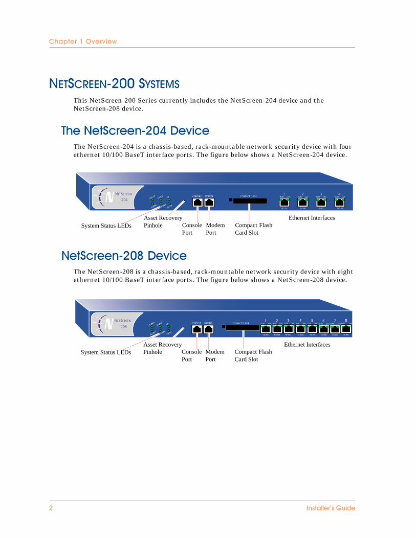
���������!"##��$�����This NetScreen-200 Series currently includes the NetScreen-204 device and the NetScreen-208 device.
�/� ��!�����,-.0$�� ��The NetScreen-204 is a chassis-based, rack-mountable network security device with four ethernet 10/100 BaseT interface ports. The figure below shows a NetScreen-204 device.
��!�����,-.1$�� ��The NetScreen-208 is a chassis-based, rack-mountable network security device with eight ethernet 10/100 BaseT interface ports. The figure below shows a NetScreen-208 device.
System Status LEDsAsset RecoveryPinhole Console
PortModemPort
Compact FlashCard Slot
Ethernet Interfaces
System Status LEDsAsset RecoveryPinhole Console
PortModemPort
Compact FlashCard Slot
Ethernet Interfaces
- ������������ ��
�/�'���������
������ ��������The features shared in common by NetScreen-204 and NetScreen-208 devices include:
• A System Status LED display• An Asset Recovery Pinhole• A Console port• A Modem port• A Compact Flash Card Slot• Ethernet interfaces
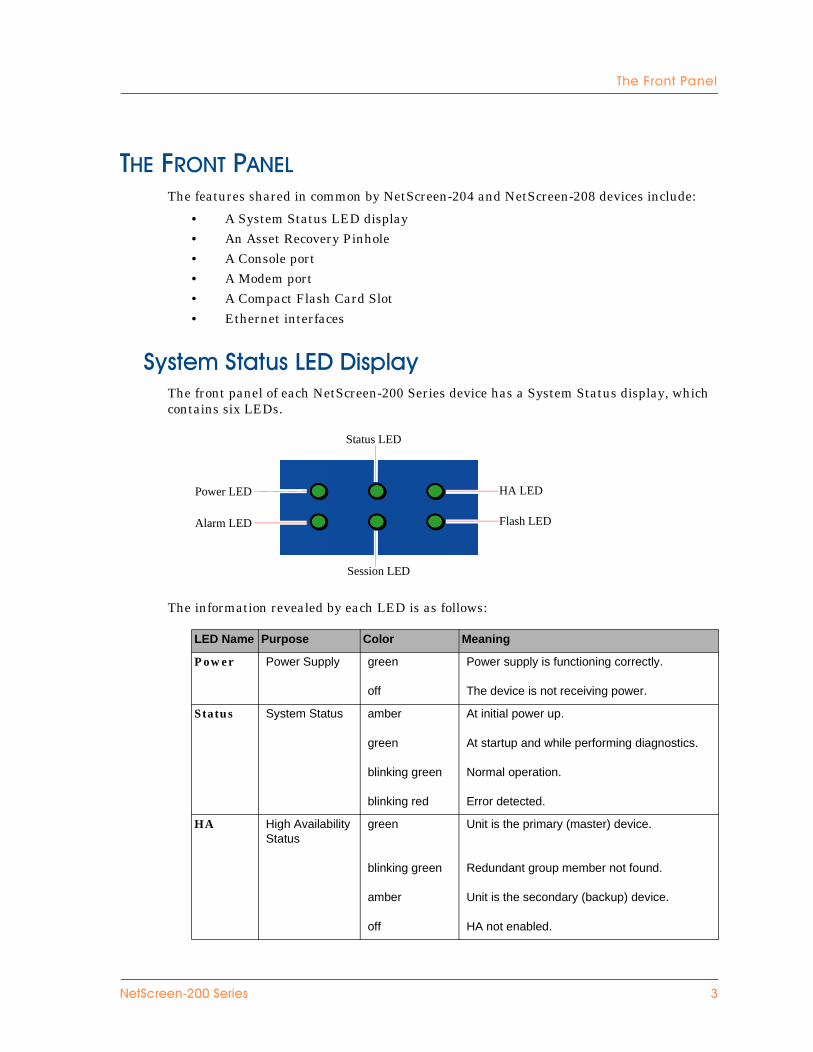
!"����!������3$$ �%��"The front panel of each NetScreen-200 Series device has a System Status display, which contains six LEDs.
The information revealed by each LED is as follows:
LED Name Purpose Color Meaning
Power Power Supply green
off
Power supply is functioning correctly.
The device is not receiving power.
Status System Status amber
green
blinking green
blinking red
At initial power up.
At startup and while performing diagnostics.
Normal operation.
Error detected.
HA High Availability Status
green
blinking green
amber
off
Unit is the primary (master) device.
Redundant group member not found.
Unit is the secondary (backup) device.
HA not enabled.
Status LED
Session LED
Power LED
Alarm LED
HA LED
Flash LED
��!�����,-..!�� �� 2
�/�%���+����� �)
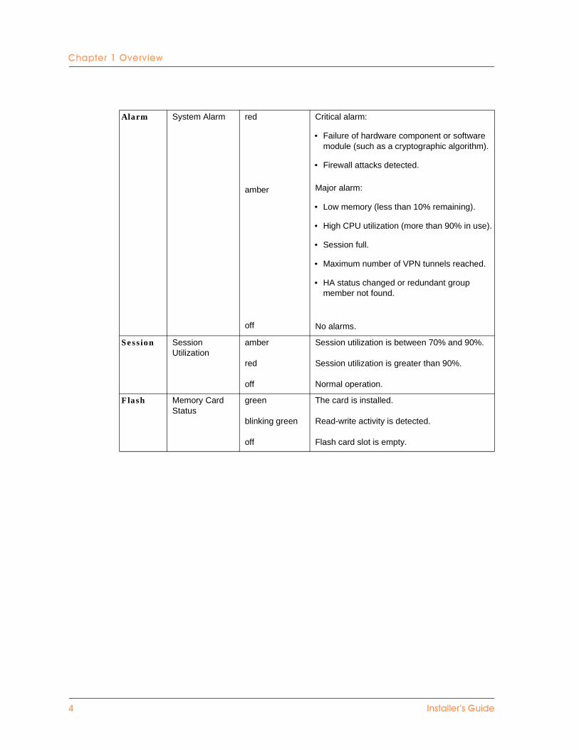
Alarm System Alarm red
amber
off
Critical alarm:
• Failure of hardware component or software module (such as a cryptographic algorithm).
• Firewall attacks detected.
Major alarm:
• Low memory (less than 10% remaining).
• High CPU utilization (more than 90% in use).
• Session full.
• Maximum number of VPN tunnels reached.
• HA status changed or redundant group member not found.
No alarms.
Session Session Utilization
amber
red
off
Session utilization is between 70% and 90%.
Session utilization is greater than 90%.
Normal operation.
Flash Memory Card Status
green
blinking green
off
The card is installed.
Read-write activity is detected.
Flash card slot is empty.
0 ������������ ��
�/�'���������
&����4������"� �/���The Asset Recovery Pinhole is a switch that resets the device to its original default settings. To use this switch, insert a stiff wire (such as a straightened paper clip) into the pinhole.
����������*���������The Console port is an RJ-45 serial console port connector, for vt100 terminal emulator programs to perform local configuration and administration.
The Modem port is an RJ-45 serial console port connector, for establishing remote console sessions using dialup connections through a 9600 bps modem connected via an RS-232 cable. Dialing into the modem establishes the dialup console connection.
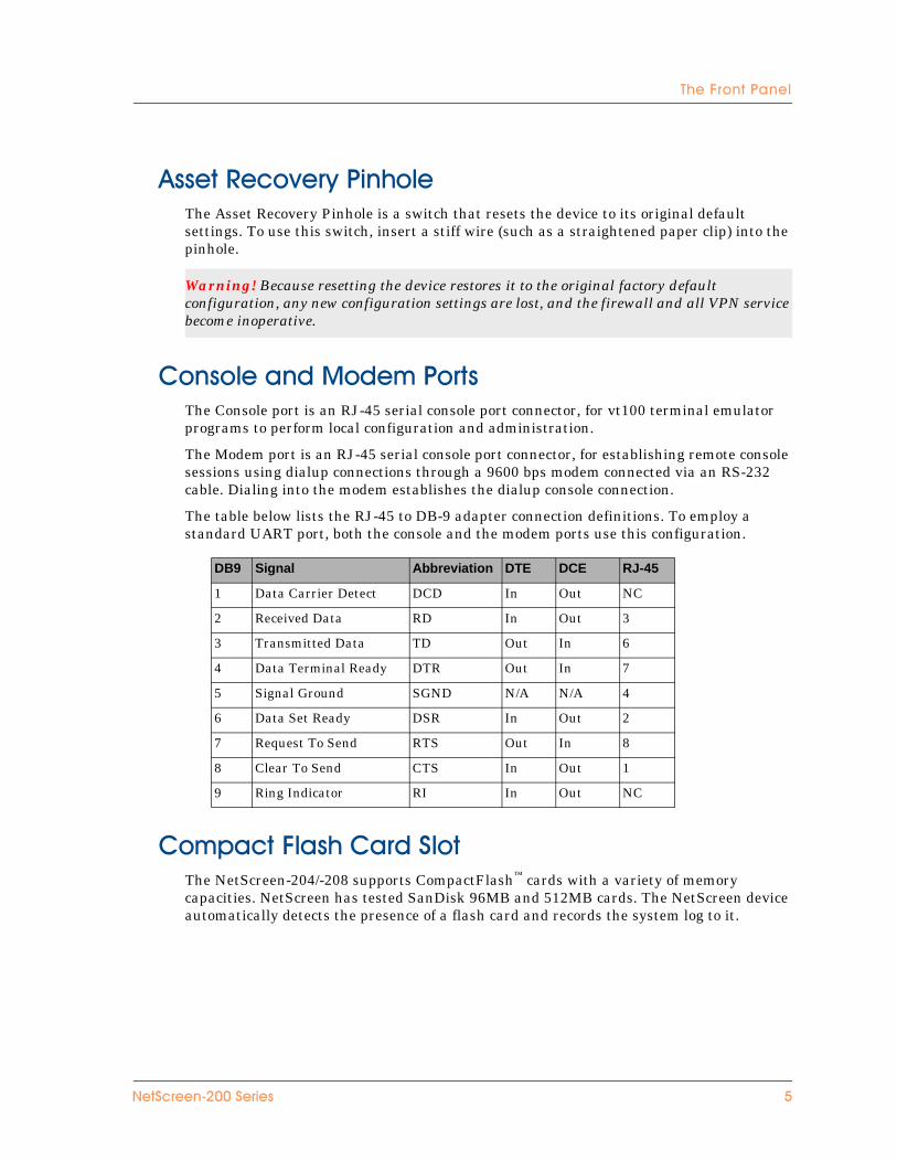
The table below lists the RJ-45 to DB-9 adapter connection definitions. To employ a standard UART port, both the console and the modem ports use this configuration.
���%���'���/����!���The NetScreen-204/-208 supports CompactFlash™ cards with a variety of memory capacities. NetScreen has tested SanDisk 96MB and 512MB cards. The NetScreen device automatically detects the presence of a flash card and records the system log to it.
Warning! Because resetting the device restores it to the original factory default configuration, any new configuration settings are lost, and the firewall and all VPN service become inoperative.
DB9 Signal Abbreviation DTE DCE RJ-45
1 Data Carrier Detect DCD In Out NC
2 Received Data RD In Out 3
3 Transmitted Data TD Out In 6
4 Data Terminal Ready DTR Out In 7
5 Signal Ground SGND N/A N/A 4
6 Data Set Ready DSR In Out 2
7 Request To Send RTS Out In 8
8 Clear To Send CTS In Out 1
9 Ring Indicator RI In Out NC
��!�����,-..!�� �� 5
�/�%���+����� �)
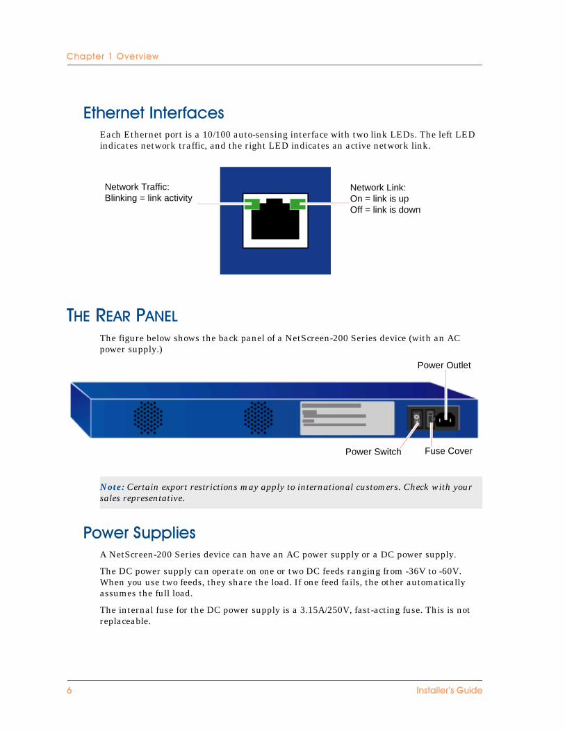
3�/���������������Each Ethernet port is a 10/100 auto-sensing interface with two link LEDs. The left LED indicates network traffic, and the right LED indicates an active network link.
��������������The figure below shows the back panel of a NetScreen-200 Series device (with an AC power supply.)
��)��!�%%� ��A NetScreen-200 Series device can have an AC power supply or a DC power supply.
The DC power supply can operate on one or two DC feeds ranging from -36V to -60V. When you use two feeds, they share the load. If one feed fails, the other automatically assumes the full load.
The internal fuse for the DC power supply is a 3.15A/250V, fast-acting fuse. This is not replaceable.
Note: Certain export restrictions may apply to international customers. Check with your sales representative.
Network Traffic:Blinking = link activity
Network Link:On = link is upOff = link is down
Power Switch
Power Outlet
Fuse Cover
6 ������������ ��
�/�4��������
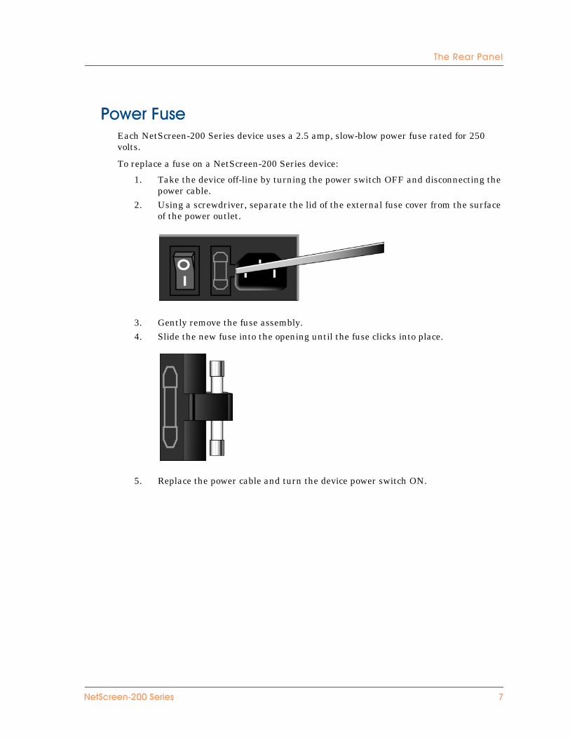
��)��'���Each NetScreen-200 Series device uses a 2.5 amp, slow-blow power fuse rated for 250 volts.
To replace a fuse on a NetScreen-200 Series device:
1. Take the device off-line by turning the power switch OFF and disconnecting the power cable.
2. Using a screwdriver, separate the lid of the external fuse cover from the surface of the power outlet.
3. Gently remove the fuse assembly.4. Slide the new fuse into the opening until the fuse clicks into place.
5. Replace the power cable and turn the device power switch ON.
��!�����,-..!�� �� 7

�/�%���+����� �)
1 ������������ ��
-��������
%&'�((�%)�'*�������This chapter describes how to install a device in an equipment rack or on a desktop, and how to connect the device to other devices.
Topics in this chapter include:
• “General Installation Guidelines” on page 10• “Performing Equipment-Rack Installation” on page 10
– “Equipment Rack Installation Guidelines” on page 10– “Rack-Mounting the Device” on page 11
• “Connecting the Power” on page 11• “Wiring a DC Power Supply” on page 12
Note: For safety warnings and instructions, please refer to the NetScreen Safety Guide. The instructions in this guide warn you about situations that could cause bodily injury. Before working on any equipment, be aware of the hazards involved with electrical circuitry and be familiar with standard practices for preventing accidents.
������������ �� 8
�/�%���-������� ���/�$�� ��
���������������� ���������Observing the following precautions can prevent injuries, equipment failures and shutdowns.
• Never assume that the power supply is disconnected from a power source. Always check first.
• Room temperature might not be sufficient to keep equipment at acceptable temperatures without an additional circulation system. Ensure that the room in which you operate the device has adequate air circulation.
• Do not work alone if potentially hazardous conditions exist.• Look carefully for possible hazards in your work area, such as moist floors,
ungrounded power extension cables, frayed power cords, and missing safety grounds.
���� ������+������!���,��������� �Although you can install a NetScreen-200 Series device on a desktop, it is advisable to install the device in an equipment rack if possible.
39� %����4��:��������� ���� ��� ���The location of the chassis and the layout of your equipment rack or wiring room are crucial for proper system operation.
Use the following guidelines while configuring your equipment rack.
• Enclosed racks must have adequate ventilation. An enclosed rack should have louvered sides and a fan to provide cooling air.
• When mounting a chassis in an open rack, ensure that the rack frame does not block the intake or exhaust ports. If you install the chassis on slides, check the position of the chassis when it is seated all the way into the rack.
• In an enclosed rack with a ventilation fan in the top, equipment higher in the rack can draw heat from the lower devices. Always provide adequate ventilation for equipment at the bottom of the rack.
• Baffles can isolate exhaust air from intake air. The best placement of the baffles depends on the airflow patterns in the rack.
You can mount the device in a standard 19-inch equipment rack. Rack mounting requires the following tools:
• 1 Phillips-head screwdriver• Rack-compatible screws • The supplied front-mount brackets
You can only front-mount a NetScreen-200 Series device.
Warning! To prevent abuse and intrusion by unauthorized personnel, it is extremely important to install the NetScreen system in a locked-room environment.
+. ������������ ��
������� ���/���)��
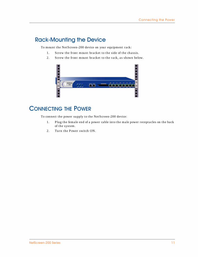
4��:,*���� ���/�$�� ��To mount the NetScreen-200 device on your equipment rack:
1. Screw the front mount bracket to the side of the chassis.2. Screw the front mount bracket to the rack, as shown below.
� ������������� ���To connect the power supply to the NetScreen-200 device:
1. Plug the female end of a power cable into the male power receptacles on the back of the system.
2. Turn the Power switch ON.
��!�����,-..!�� �� ++

�/�%���-������� ���/�$�� ��
���������� ���������$The DC power supply, ON/OFF switch, grounding screw, and terminal blocks, are located in the back of the chassis of the power supply unit.
To connect the DC power supply to a grounding point at your site:
1. Remove the hex nut on the grounding screw.2. Place the ground lug on the screw and tighten the hex nut securely.3. Connect the other end of the grounding lug wire to a grounding point at your
site.
NetScreen-200 Series devices can operate on one feed alone or two feeds. To connect DC power feeds to the terminal blocks, do the following:
1. Strip the ends of the power cables.2. Loosen the three screws in the top of the block. (These are captive screws, which
you cannot completely remove.)3. Insert the -48V DC power feed wires into the two outside receptacles of the
terminal block.4. Insert the 0V DC feed wires into the center receptacle.5. Tighten the screws over the receptacles.
Warning: You must shut off current to the DC feed wires before connecting the wires to the power supplies. Also, make sure that the ON/OFF switch is in the OFF position.
DC PowerTerminal Blocks
Power SwitchGrounding Screw
+- ������������ ��
������� ���/� ��!�����,-..$�� ������/��$�� ���
� ���������������������!"##������� � ����������
To connect the device, use the ethernet interfaces (ethernet1 through ethernet4 on the NetScreen-204, or ethernet1 through ethernet8 on the NetScreen-208). The purpose of each interface depends upon the security zone to which it is bound.
By default, the zone and interface bindings are as follows:
• ethernet1 is bound to the V1-Trust security zone by default.
Connect this interface using a twisted pair cable with RJ-45 connectors.
• ethernet2 is bound to the V1-DMZ security zone by default.
Connect this interface using a twisted pair cable with RJ-45 connectors.
• ethernet3 is bound to the V1-Untrust security zone by default.
Connect this interface using a twisted pair cable with RJ-45 connectors.
• ethernet4 through ethernet8: Can be connected as required.
The default IP address of each ethernet interface is 0.0.0.0.
For information on interfaces and security zones, see “The NetScreen-200 Interfaces” on page 17.
��!�����,-..!�� �� +2

�/�%���-������� ���/�$�� ��
+0 ������������ ��
2��������
�-%��).��%)�'*�������This chapter describes how to perform initial configuration on a NetScreen-200 Series device once you have mounted it in a rack or desktop, plugged in the necessary cables, and turned the power on.
Topics in this chapter include:
• “Operational Modes” on page 16– “Transparent Mode” on page 16– “Route Mode” on page 16
• “The NetScreen-200 Interfaces” on page 17• “Connecting the Device as a Single Security Gateway” on page 18
– “Connectivity Examples” on page 18– “Performing Device Connection” on page 19
• “Establishing an HA Connection Between Devices” on page 20• “Performing Initial Connection and Configuration” on page 22
– “Establishing a Terminal Emulator Connection” on page 22– “Changing Your Login Name and Password” on page 23– “Setting Port and Interface IP Addresses” on page 23
• “Configuring the Device for Telnet and WebUI Sessions” on page 25– “Starting a Console Session Using Telnet” on page 25– “Starting a Console Session Using Dialup” on page 26– “Establishing a GUI Management Session” on page 26
• “Resetting the Device to Factory Default Settings” on page 27
Note: For safety warnings and instructions, please refer to the NetScreen Safety Guide. The instructions in this guide warn you about situations that could cause bodily injury. Before working on any equipment, be aware of the hazards involved with electrical circuitry and be familiar with standard practices for preventing accidents.
������������ �� +5
�/�%���2���� ��� ���/�$�� ��
����� ����� ��The NetScreen-200 Series supports two device modes, Transparent mode and Route mode. The default mode is Transparent.
�����%�����*���In Transparent mode, the NetScreen-200 device operates as a Layer-2 bridge. Because the device cannot translate packet IP addresses, it cannot perform Network Address Translation (NAT). Consequently, for the device to access the Internet, any IP address in your trusted (local) networks must be routable and accessible from untrusted (external) networks.
In Transparent mode, the IP addresses for the Layer-2 security zones V1-Trust, V1-DMZ, and V1-Untrust are 0.0.0.0, thus making the NetScreen device invisible to the network. However, the device can still perform firewall, VPN, and traffic management according to configured security policies.
4����*���In Route mode, the NetScreen-200 device operates at Layer 3. Because you can configure each interface using an IP address and subnet mask, you can configure individual interfaces to perform NAT.
• When the interface performs NAT services, the device translates the source IP address of each outgoing packet into the IP address of the untrusted port. It also replaces the source port number with a randomly-generated value.
• When the interface does not perform NAT services, the source IP address and port number in each packet header remain unchanged. Therefore, to reach the Internet your local hosts must have routable IP addresses.
For more information on NAT, see the NetScreen Concepts and Examples ScreenOS Reference Guide.
Important! Performing the setup instructions below configures your device in Route mode. To configure your device in Transparent mode, see the NetScreen Concepts and Examples ScreenOS Reference Guide.
+6 ������������ ��
�/� ��!�����,-..����������
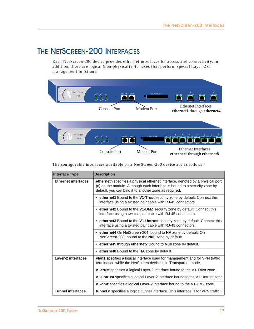
�������������!"##����������Each NetScreen-200 device provides ethernet interfaces for access and connectivity. In addition, there are logical (non-physical) interfaces that perform special Layer-2 or management functions.
The configurable interfaces available on a NetScreen-200 device are as follows:
Interface Type Description
Ethernet interfaces ethernetn specifies a physical ethernet interface, denoted by a physical port (n) on the module. Although each interface is bound to a security zone by default, you can bind it to another zone as required.
• ethernet1 Bound to the V1-Trust security zone by default. Connect this interface using a twisted pair cable with RJ-45 connectors.
• ethernet2 Bound to the V1-DMZ security zone by default. Connect this interface using a twisted pair cable with RJ-45 connectors.
• ethernet3 Bound to the V1-Untrust security zone by default. Connect this interface using a twisted pair cable with RJ-45 connectors.
• ethernet4 On NetScreen-204, bound to HA zone by default. On NetScreen-208, bound to the Null zone by default.
• ethernet5 through ethernet7 Bound to Null zone by default.
• ethernet8 Bound to the HA zone by default.
Layer-2 interfaces vlan1 specifies a logical interface used for management and for VPN traffic termination while the NetScreen device is in Transparent mode.
v1-trust specifies a logical Layer-2 interface bound to the V1-Trust zone.
v1-untrust specifies a logical Layer-2 interface bound to the V1-Untrust zone.
v1-dmz specifies a logical Layer-2 interface bound to the V1-DMZ zone.
Tunnel interfaces tunnel.n specifies a logical tunnel interface. This interface is for VPN traffic.
Ethernet Interfacesethernet1 through ethernet8Modem PortConsole Port
Ethernet Interfacesethernet1 through ethernet4Modem PortConsole Port
��!�����,-..!�� �� +7
�/�%���2���� ��� ���/�$�� ��
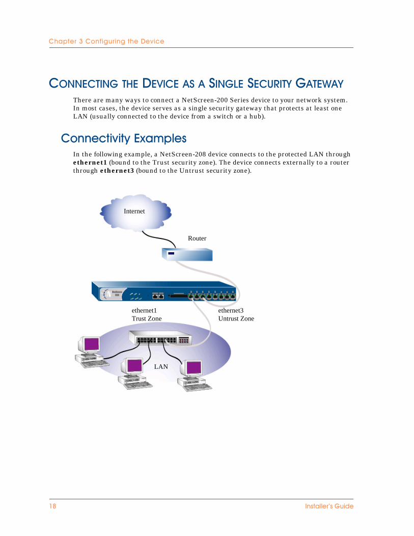
� ����������������������������������$�������$There are many ways to connect a NetScreen-200 Series device to your network system. In most cases, the device serves as a single security gateway that protects at least one LAN (usually connected to the device from a switch or a hub).
������� � �"3#��%���In the following example, a NetScreen-208 device connects to the protected LAN through ethernet1 (bound to the Trust security zone). The device connects externally to a router through ethernet3 (bound to the Untrust security zone).
Router
Internet
ethernet3Untrust Zone
ethernet1Trust Zone
LAN
+1 ������������ ��
������� ���/�$�� �����! ����!���� �"����)�"
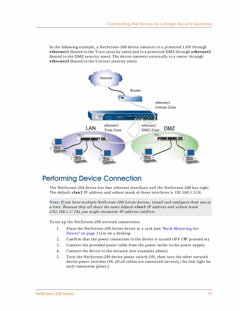
In the following example, a NetScreen-208 device connects to a protected LAN through ethernet1 (bound to the Trust security zone) and to a protected DMZ through ethernet2 (bound to the DMZ security zone). The device connects externally to a router through ethernet3 (bound to the Untrust security zone).
������� ��$�� ��������� ��The NetScreen-204 device has four ethernet interfaces and the NetScreen-208 has eight. The default vlan1 IP address and subnet mask of these interfaces is 192.168.1.1/24.
To set up the NetScreen-200 network connections:
1. Place the NetScreen-200 Series device in a rack (see “Rack-Mounting the Device” on page 11) or on a desktop.
2. Confirm that the power connection to the device is turned OFF (“0” pressed in).3. Connect the provided power cable from the power outlet to the power supply.4. Connect the device to the network (see examples above).5. Turn the NetScreen-200 device power switch ON, then turn the other network
device power switches ON. (If all cables are connected correctly, the link light for each connection glows.)
Note: If you have multiple NetScreen-200 Series devices, install and configure them one at a time. Because they all share the same default vlan1 IP address and subnet mask (192.168.1.1/24), you might encounter IP address conflicts.
Router
Internet
ethernet2DMZ Zone
ethernet1Trust Zone
ethernet3Untrust Zone
��!�����,-..!�� �� +8
�/�%���2���� ��� ���/�$�� ��
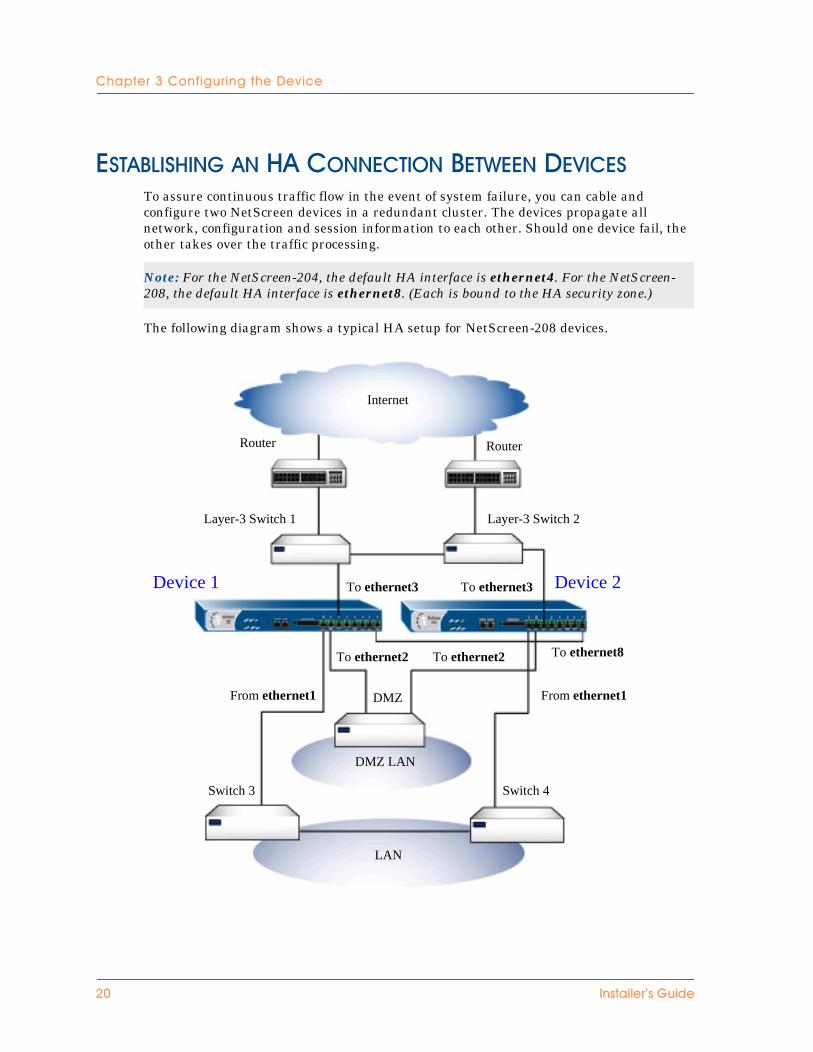
������������������ ����� ���������������To assure continuous traffic flow in the event of system failure, you can cable and configure two NetScreen devices in a redundant cluster. The devices propagate all network, configuration and session information to each other. Should one device fail, the other takes over the traffic processing.
The following diagram shows a typical HA setup for NetScreen-208 devices.
Note: For the NetScreen-204, the default HA interface is ethernet4. For the NetScreen-208, the default HA interface is ethernet8. (Each is bound to the HA security zone.)
RouterRouter
Layer-3 Switch 2Layer-3 Switch 1
To ethernet3To ethernet3
To ethernet2 To ethernet2 To ethernet8
From ethernet1 DMZ
DMZ LAN
Switch 4Switch 3
Internet
From ethernet1
Device 1 Device 2
LAN
-. ������������ ��

3����� �/ ����(&������� ��<��)���$�� ���
To cable two NetScreen-200 devices together for HA and connect them to the network:
1. (Optional) Install the NetScreen-200 devices in an equipment rack (see “Equipment Rack Mounting” on page 12).
2. Make sure that all ON/OFF power supply switches are OFF.3. Connect the power cables to each NetScreen-200 power supply and connect them
to a power source.
4. If your device is a NetScreen-204, connect a 10/100 BaseT cable from the ethernet4 on Device 1 to the ethernet4 port on Device 2.
or
If your device is a NetScreen-208, connect a 10/100 BaseT cable from the ethernet8 on Device 1 to the ethernet8 port on Device 2.
$�� ��+
5. On Device 1, connect a 10/100 BaseT cable from ethernet1 to the switch labeled “Switch 3.”
6. On Device 1, connect a 10/100 BaseT cable from ethernet2 to the switch labeled “DMZ.”
7. On Device 1, connect a 10/100 BaseT cable from ethernet3 to the switch labeled “Layer 3 switch 1.”
$�� ��-
8. On Device 2, connect a 10/100 BaseT cable from ethernet1 to the switch labeled “Switch 4.”
9. On Device 2, connect a 10/100 BaseT cable from ethernet2 to the switch labeled “DMZ.”
10. On Device 2, connect a 10/100 BaseT cable from ethernet3 to the switch labeled “Layer 3 switch 2.”
!) ��/��
11. Cable together the switches labeled “Switch 3” and “Switch 4.”12. Cable together the switches labeled “Layer 3 switch 1” and “Layer 3 switch 2.”
Note: The cabling instructions given below reproduce the configuration shown here. However, this is not the only possible HA configuration. In addition, the instructions assume that all physical ports and interfaces are still set at their default settings. If you have changed the port and interface configurations, the instructions below might not work properly.
Note: Whenever you deploy two NetScreen-200 devices in an HA cluster, connect each to a different power source, if possible. If one power source fails, the other source might still be operative.
��!�����,-..!�� �� -+
�/�%���2���� ��� ���/�$�� ��
13. Cable the switches labeled “Layer 3 switch 1” and “Layer 3 switch 2” to routers.
14. Turn the power switches for all devices ON.
For more advanced HA configurations, see the NetScreen Concepts and Examples ScreenOS Reference Guide.
���� ����������� ����� ������ ������� �To establish the first console session with the NetScreen-200 Series device, use a vt100 terminal emulator program through the provided RJ-45/DB9 serial port connector.
3����� �/ ������� ���3�������������� ��To establish an initial console session:
1. Plug the DB9 end of the supplied RJ-45/DB-9 serial cable into the serial port of your PC. (Be sure that the DB-9 is seated properly by screwing in the thumbscrews.)
2. Plug the RJ-45 end of the cable into the Console port of the NetScreen-200 Series device. (Be sure that the RJ-45 clip snaps into the port and is seated properly.)
3. Launch a Command Line Interface (CLI) session between your PC and the NetScreen-200 device using a standard serial terminal emulation program such as Hilgreave Hyperterminal (provided with your Windows PC). The settings should be as follows:
• Baud Rate to 9600
• Parity to No
• Data Bits to 8
• Stop Bit to 1
• Flow Control to none
4. Press the ENTER key to see the login prompt.5. At the login prompt, type netscreen.6. At the password prompt, type netscreen.
Note: The switch ports must be defined as 802.1Q trunk ports, and the external routers must be able to use either Hot Standby Router Protocol (HSRP) or Virtual Router Redundancy Protocol (VRRP). For the best configuration method, see the documentation for your switch or router.
Note: Use lowercase letters only. Both login and password are case-sensitive.
-- ������������ ��
������� ���� � ��������� ��������� ����� ��
7. (Optional) By default, the console times out and terminates automatically after 10 minutes of idle time. To change this timeout interval, execute the following command:
set console timeout number
where number is the length of idle time in minutes before session termination. To prevent any automatic termination, specify a value of 0.
�/��� ��=������ � ����������)���Because all NetScreen products use the same login name and password (netscreen), it is highly advisable to change your login name and password immediately. Enter the following commands:
set admin name name_strset admin password pswd_strsave
For information on creating different levels of administrators, see “Administration” in the NetScreen Concepts and Examples ScreenOS Reference Guide.
!��� ��������������������&��������Through the CLI, you can execute commands that set IP address and subnet mask values for most of the physical interfaces.
� �) ������������������!��� ���To begin the configuration process, it is advisable to view existing port settings by executing the following command:
get interface
This command displays current port names, IP addresses, MAC addresses, and other useful information.
!��� ���/���&���������/�*������������������To make an interface work as the management interface, you must set the IP address and subnet mask to the same address range as your PC (or LAN). Use the CLI save command to save your configuration changes.
To configure the ethernet1 interface to serve as a management interface:
1. Determine the IP address and subnet mask for your PC (or LAN).2. Assign the IP address and subnet mask to the ethernet1 interface by executing
the following command:
set interface ethernet1 ip ip_addr/mask
where ip_addr is the IP address and mask is the subnet mask. For example, to set the IP address and subnet mask of ethernet1 to 10.100.2.183/16:
��!�����,-..!�� �� -2
�/�%���2���� ��� ���/�$�� ��
set interface ethernet1 ip 10.100.2.183/16
3. Enable management on the ethernet1 interface by executing the following command:
set interface ethernet1 manage
4. (Optional) To confirm the new interface settings, execute the following command:
get interface ethernet1
!��� ���/���&����������/�>������?������������The NetScreen-200 device usually communicates with external devices through an interface bound to the Untrust zone (such as ethernet3). To allow an interface to communicate with external devices, you must assign it a public IP address.
To set the IP address and subnet mask for ethernet3:
1. Choose an unused public IP address and subnet mask.2. Set the ethernet3 interface to this IP address and subnet mask by executing
the following command:
set interface ethernet3 ip ip_addr/mask
where ip_addr is the IP address and mask is the subnet mask. For example, to set the IP address and subnet mask of the ethernet3 interface to 172.16.2.183/16:
set interface ethernet3 ip 172.16.2.183/16
3. (Optional) To confirm the new port settings, execute the following command:
get interface ethernet3
&���) ��������������� �By default, the NetScreen-200 Series device does not allow inbound or outbound traffic, nor does it allow traffic to or from the DMZ. To permit (or deny) traffic, you must create access policies.
The following CLI command creates an access policy that permits all kinds of outbound traffic, from any host in your trusted LAN to any device on the untrusted network.
set policy from trust to untrust any any any permitsave
Important! Your network might require a more restrictive policy than the one created in the example above. The example is NOT a requirement for initial configuration. For detailed information about access policies, see the NetScreen Concepts and Examples ScreenOS Reference Guide.
-0 ������������ ��
���� ��� ���/�$�� ��������������;��>�!��� ���
You can also use the Outgoing Policy Wizard in the WebUI management application to create access policies for outbound traffic. See “Establishing a GUI Management Session” on page 26 for information on accessing the WebUI application.
�/��� ��=������ � ����������)���Because all NetScreen products use the same default login name and password (netscreen), it is highly advisable to change them immediately.
To change the login name and password:
set admin name name_strset admin password pswd_strsave
� ������������������ ��������������������� ��In addition to terminal emulator programs, you can use Telnet (or dialup) to establish console sessions with the NetScreen-200 device. In addition, you can start management sessions using the NetScreen WebUI, a web-based GUI management application.
!���� ����������!��� ��>� ��������To establish a Telnet session with the NetScreen-200 device:
1. Connect an RJ-45 cable from ethernet1 to the internal switch, router, or hub in your LAN (see “Connecting the Device as a Single Security Gateway” on page 18).
2. Open a Telnet session, specifying the current IP address for ethernet1. For example, in Windows, click Start >> Run, enter telnet ip_addr (where ip_addr is the address of the ethernet1 interface) and then click OK.
For example, if the current address of the ethernet1 interface is 10.100.2.183, enter:
telnet 10.100.2.183
3. At the Username prompt, type your user name (default is netscreen).4. At the Password prompt, type your password (default is netscreen).
5. (Optional) By default, the console times out and terminates automatically after 10 minutes of idle time. To change this timeout interval, execute the following command:
Note: If you forget your password, see “Resetting the Device to Factory Default Settings” on page 27.
Note: Use lowercase letters only. Both Username and Password are case-sensitive.
��!�����,-..!�� �� -5
�/�%���2���� ��� ���/�$�� ��
set console timeout number
where number is the length of idle time in minutes before session termination. To prevent any automatic termination, specify a value of 0.
!���� ����������!��� ��>� ��$ ���%Each NetScreen-200 device provides a modem port that allows you to establish a remote console session using a dialup connection through a 9600 bps modem cabled to the modem port. Dialing into the modem establishes a dialup console connection.
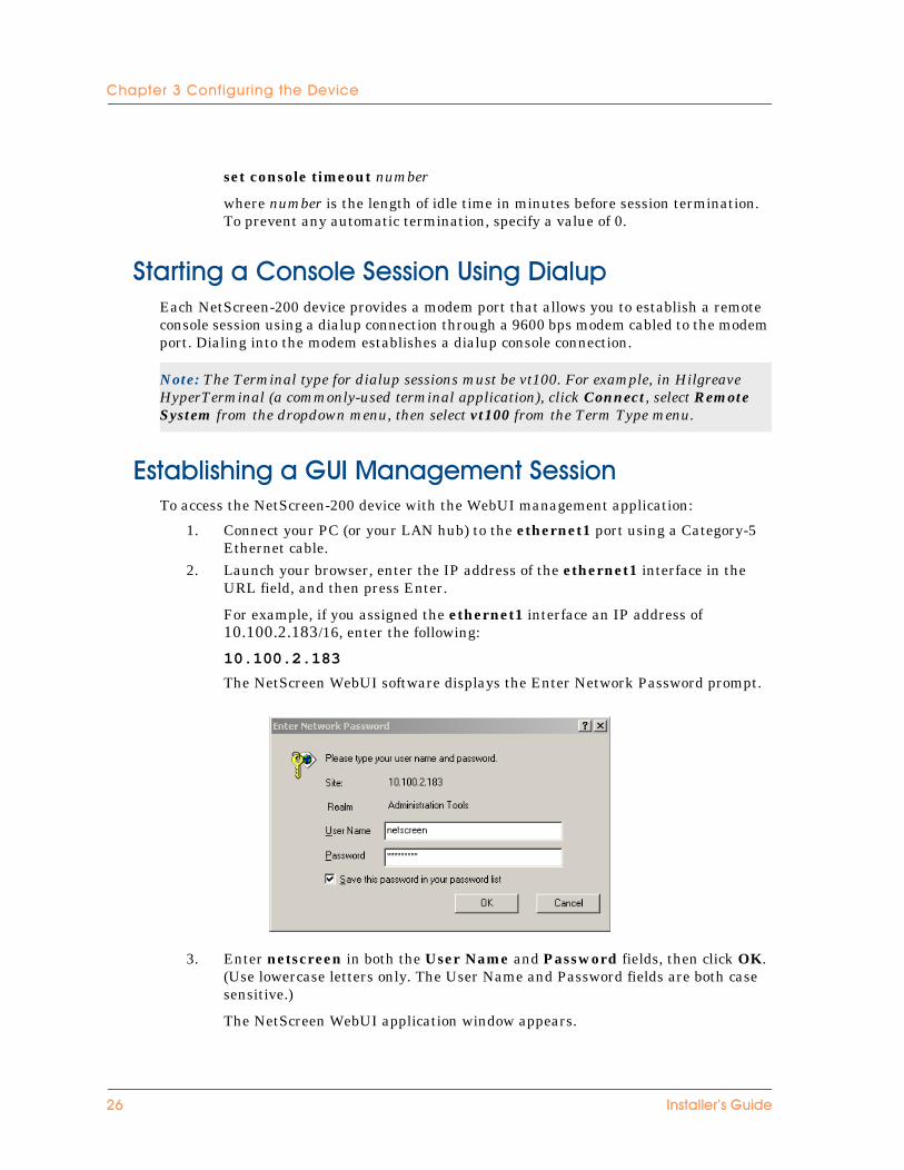
3����� �/ ����>�*���������!��� ��To access the NetScreen-200 device with the WebUI management application:
1. Connect your PC (or your LAN hub) to the ethernet1 port using a Category-5 Ethernet cable.
2. Launch your browser, enter the IP address of the ethernet1 interface in the URL field, and then press Enter.
For example, if you assigned the ethernet1 interface an IP address of 10.100.2.183/16, enter the following:
10.100.2.183
The NetScreen WebUI software displays the Enter Network Password prompt.
3. Enter netscreen in both the User Name and Password fields, then click OK. (Use lowercase letters only. The User Name and Password fields are both case sensitive.)
The NetScreen WebUI application window appears.
Note: The Terminal type for dialup sessions must be vt100. For example, in Hilgreave HyperTerminal (a commonly-used terminal application), click Connect, select Remote System from the dropdown menu, then select vt100 from the Term Type menu.
-6 ������������ ��
4����� ���/�$�� ����'�����"$������!��� ���
������������������� ����� �$���������������If you lose the admin password, you can use one of the following procedures to reset the NetScreen device to its default settings. This destroys any existing configurations, but restores access to the device.
>� ���������������4�����/�$�� ��To perform this operation, you need to make a console connection, as described in “Establishing a Terminal Emulator Connection” on page 22.
1. At the login prompt, type the serial number of the device.2. At the password prompt, type the serial number again.
The following message appears:
!!! Lost Password Reset !!! You have initiated a command to reset the device to factory defaults, clearing all current configuration, keys and settings. Would you like to continue? y/[n]
3. Press the y key.
The following message appears:
!! Reconfirm Lost Password Reset !! If you continue, the entire configuration of the device will be erased. In addition, a permanent counter will be incremented to signify that this device has been reset. This is your last chance to cancel this command. If you proceed, the device will return to factory default configuration, which is: System IP: 192.168.1.1; username: netscreen; password: netscreen. Would you like to continue? y/[n]
4. Press the y key to rest the device.
You can now login in using netscreen as the default username and password.
Warning! Resetting the device will delete all existing configuration settings, and the firewall and VPN service will be rendered inoperative.
Note: After you successfully reset and reconfigure the NetScreen device, you should back up the new configuration setting. As a precaution against lost passwords, you should back up a new configuration that contains the NetScreen default password. This will ensure a quick recovery of a lost configuration. You should change the password on the system as soon as possible.
Note: By default the device recovery feature is enabled. You can disable it by entering the following CLI command: unset admin device-reset
��!�����,-..!�� �� -7
�/�%���2���� ��� ���/�$�� ��
>� ���/�&����4������"� �/�����4�����/�$�� ��You can also reset the device and restore the factory default settings by pressing the asset recovery pinhole. To perform this operation, you need to make a console connection, as described in “Establishing a Terminal Emulator Connection” on page 22.
1. Locate the asset recovery pinhole on the front panel (see “The Front Panel” on page 3). Using a thin, firm wire (such as a paper clip), push the pinhole for four to six seconds and then release.
A serial console message states that the “Configuration Erasure Process has been initiated” and the system sends an SNMP/SYSLOG alert. The Status LED blinks amber once every second.
2. Wait for one-half to two seconds.
After the first reset is accepted, the power LED blinks green; the device is now waiting for the second push. The serial console message now reads, “Waiting for 2nd confirmation.”
3. Push the reset pinhole again for four to six seconds.
The Status LED lights amber for one-half second, and then returns to the blinking green state.
4. The device resets to its original factory settings.
When the device resets, the Status LED will turn amber for one-half second and then return to the blinking green state. The serial console message states “Configuration Erase sequence accepted, unit reset.” The system generates SNMP and SYSLOG alerts to configured SYSLOG or SNMP trap hosts.
5. The device now reboots.
If you do not follow the complete sequence, the reset process cancels without any configuration change and the serial console message states, “Configuration Erasure Process aborted.” The status LED returns to blinking green. If the unit did not reset, an SNMP alert is sent to confirm the failure.
Note: During a reset, there is no guarantee that the final SNMP alert sent to the receiver before the reset will be received.
-1 ������������ ��
&����������
�/�������'�-%&This appendix provides general system specifications for the NetScreen-200 Series devices.
• “NetScreen-200 Attributes” on page 2• “Electrical Specification” on page 2• “Environmental” on page 2• “Safety Certifications” on page 2• “EMI Certifications” on page 2
������������ �� &,+
&%%��� #&!%�� � ��� ���
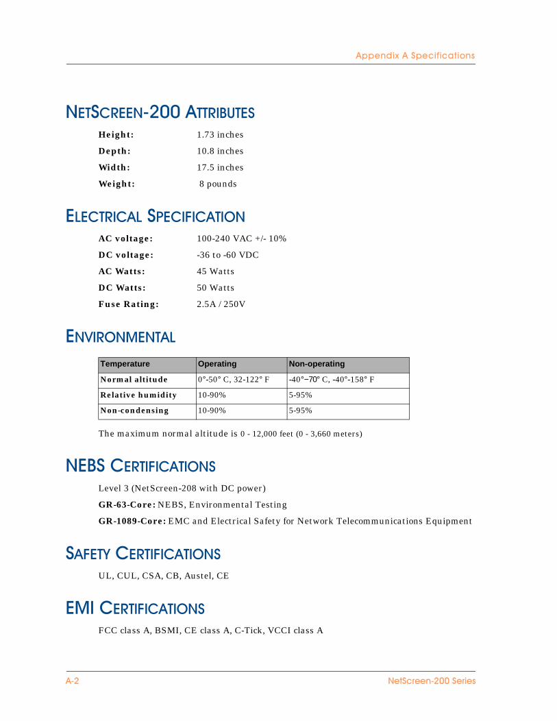
���������!"##����������Height: 1.73 inches
Depth: 10.8 inches
Width: 17.5 inches
Weight: 8 pounds
������������������ �AC voltage: 100-240 VAC +/- 10%
DC voltage: -36 to -60 VDC
AC Watts: 45 Watts
DC Watts: 50 Watts
Fuse Rating: 2.5A / 250V
���� �������
The maximum normal altitude is 0 - 12,000 feet (0 - 3,660 meters)
������������� ��Level 3 (NetScreen-208 with DC power)
GR-63-Core: NEBS, Environmental Testing
GR-1089-Core: EMC and Electrical Safety for Network Telecommunications Equipment
�����$��������� ��UL, CUL, CSA, CB, Austel, CE
����������� ��FCC class A, BSMI, CE class A, C-Tick, VCCI class A
Temperature Operating Non-operating
Normal altitude 0°-50° C, 32-122° F -40°−70° C, -40°-158° F
Relative humidity 10-90% 5-95%
Non-condensing 10-90% 5-95%
&,- ��!�����,-..!�� ��
<���������
�-%��).��'�-%��-���-00-%����'����1����"
All NetScreen devices are designed to meet the Common Criteria requirements, and are currently under evaluation for Common Criteria, EAL2. However, there are certain configuration actions that are required for a security administrator to properly secure the device to be in compliance with the Common Criteria EAL2 security target. While these requirements are for anyone needing Common Criteria assurance, they can also be used as general guidelines for administrators wishing to better secure the deployment of a NetScreen device.
�� ����$�����$����������������������� ��� �� ������������"�� �������
Before carrying out any step to secure a NetScreen device, you must make sure that the received product has not been tampered with, and ensure that the product received matches the version that is certified as Common Criteria EAL2 compliant.
To ensure that the product has not been tampered with, verify two items:
• The outside packaging cannot show damage, or evidence that it has been opened. If the cardboard shows damage that would allow the device to be removed or exchanged, this may be evidence of tampering.
• The internal packaging cannot show damage or evidence of tampering. The plastic bag should not have a large hole and the label that seals the plastic bag should not be detached or missing. If the bag or the seal are damaged in any way, this may be evidence of tampering.
Both of these tamper evidence criteria must be met to ensure that the product has not been tampered with during shipment.
To verify that the product received is the correct version of hardware and software, run the following command from the Command Line Interface (CLI):
get system
The output of this command includes two key items, hardware version and software version. The Common Criteria evaluated versions are listed in NetScreen’s Security Target for Common Criteria EAL2, section 1.1. The hardware and software versions must match the Security Target to be in full compliance with the Common Criteria evaluation.
������������ �� <,+
&%%��� #<���� ����� ������������� ��� �@3&�-
�� ����������� �������������������������� ��� �� ������������"�� �������
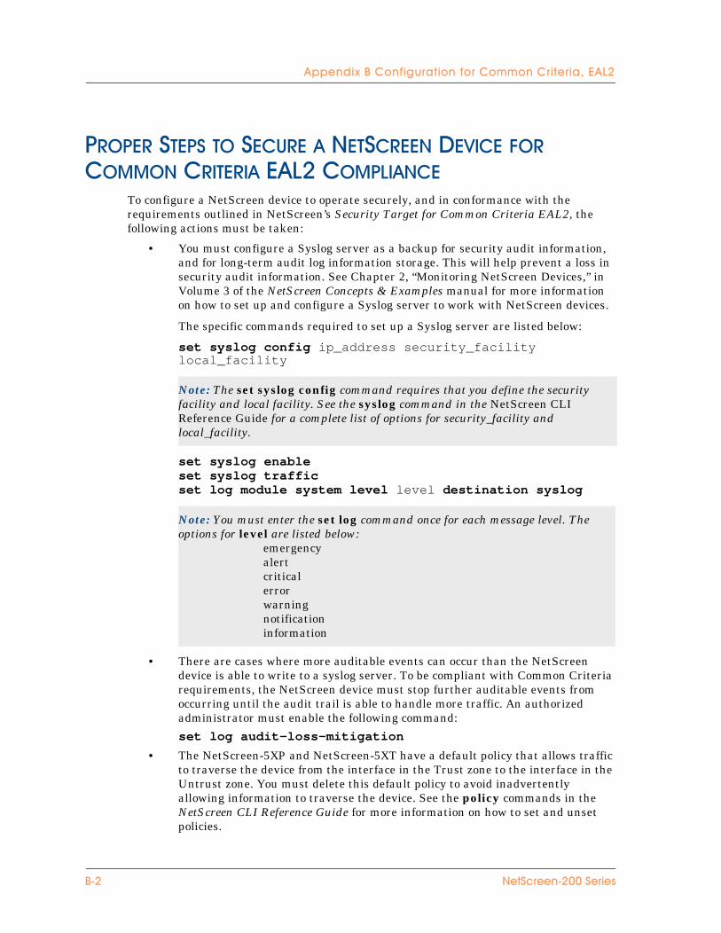
To configure a NetScreen device to operate securely, and in conformance with the requirements outlined in NetScreen’s Security Target for Common Criteria EAL2, the following actions must be taken:
• You must configure a Syslog server as a backup for security audit information, and for long-term audit log information storage. This will help prevent a loss in security audit information. See Chapter 2, “Monitoring NetScreen Devices,” in Volume 3 of the NetScreen Concepts & Examples manual for more information on how to set up and configure a Syslog server to work with NetScreen devices.
The specific commands required to set up a Syslog server are listed below:
set syslog config ip_address security_facility local_facility
set syslog enableset syslog trafficset log module system level level destination syslog
• There are cases where more auditable events can occur than the NetScreen device is able to write to a syslog server. To be compliant with Common Criteria requirements, the NetScreen device must stop further auditable events from occurring until the audit trail is able to handle more traffic. An authorized administrator must enable the following command:
set log audit-loss-mitigation
• The NetScreen-5XP and NetScreen-5XT have a default policy that allows traffic to traverse the device from the interface in the Trust zone to the interface in the Untrust zone. You must delete this default policy to avoid inadvertently allowing information to traverse the device. See the policy commands in the NetScreen CLI Reference Guide for more information on how to set and unset policies.
Note: The set syslog config command requires that you define the security facility and local facility. See the syslog command in the NetScreen CLI Reference Guide for a complete list of options for security_facility and local_facility.
Note: You must enter the set log command once for each message level. The options for level are listed below:
emergencyalertcriticalerrorwarningnotificationinformation
<,- ��!�����,-..!�� ��
&%%��� #<���� ����� ������������� ��� �@3&�-
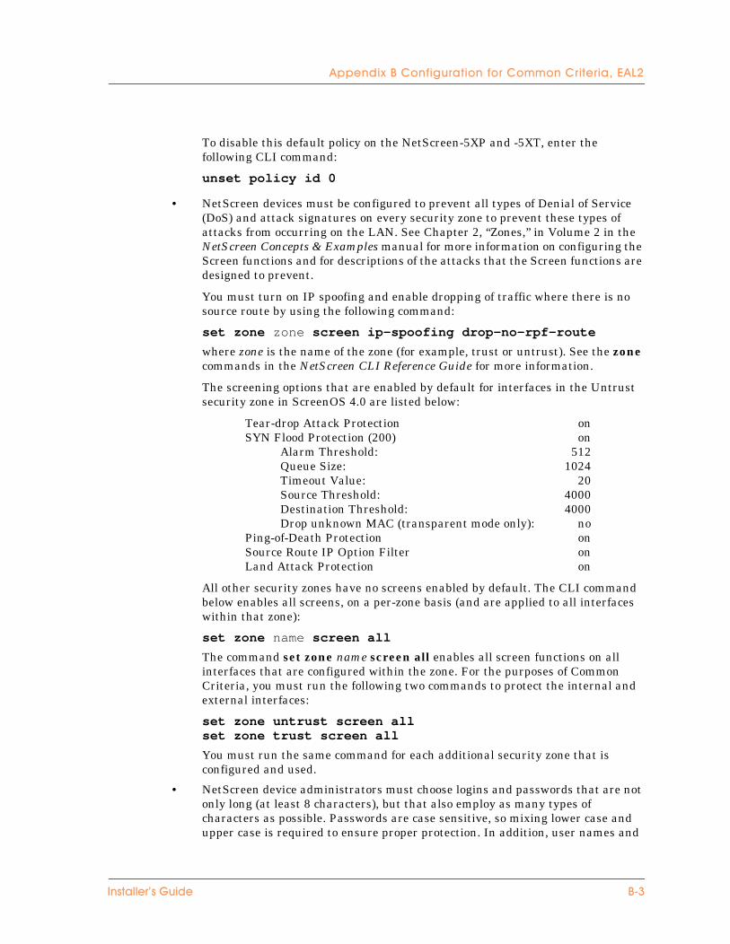
To disable this default policy on the NetScreen-5XP and -5XT, enter the following CLI command:
unset policy id 0
• NetScreen devices must be configured to prevent all types of Denial of Service (DoS) and attack signatures on every security zone to prevent these types of attacks from occurring on the LAN. See Chapter 2, “Zones,” in Volume 2 in the NetScreen Concepts & Examples manual for more information on configuring the Screen functions and for descriptions of the attacks that the Screen functions are designed to prevent.
You must turn on IP spoofing and enable dropping of traffic where there is no source route by using the following command:
set zone zone screen ip-spoofing drop-no-rpf-route
where zone is the name of the zone (for example, trust or untrust). See the zone commands in the NetScreen CLI Reference Guide for more information.
The screening options that are enabled by default for interfaces in the Untrust security zone in ScreenOS 4.0 are listed below:
Tear-drop Attack Protection onSYN Flood Protection (200) on
Alarm Threshold: 512Queue Size: 1024Timeout Value: 20Source Threshold: 4000Destination Threshold: 4000Drop unknown MAC (transparent mode only): no
Ping-of-Death Protection onSource Route IP Option Filter onLand Attack Protection on
All other security zones have no screens enabled by default. The CLI command below enables all screens, on a per-zone basis (and are applied to all interfaces within that zone):
set zone name screen all
The command set zone name screen all enables all screen functions on all interfaces that are configured within the zone. For the purposes of Common Criteria, you must run the following two commands to protect the internal and external interfaces:
set zone untrust screen allset zone trust screen all
You must run the same command for each additional security zone that is configured and used.
• NetScreen device administrators must choose logins and passwords that are not only long (at least 8 characters), but that also employ as many types of characters as possible. Passwords are case sensitive, so mixing lower case and upper case is required to ensure proper protection. In addition, user names and
������������ �� <,2

&%%��� #<���� ����� ������������� ��� �@3&�-
passwords should not be easily guessed, such as a mother’s maiden name, a birth date, or names of relatives. NetScreen devices ship with a default user name and password of “netscreen”. You must change this as soon as possible to prevent unauthorized access. See Chapter 1, “Administration,” in Volume 3 in the NetScreen Concepts & Examples manual for more information on administrative passwords. The recommended time between password changes is no longer than 30 days to mitigate the effects of a compromised administrator identity.
The following CLI commands, in order, are required to set a new administrator name and password:
set admin name nameset admin password password
• It is expected and assumed that authorized administrators are not hostile.• The NetScreen device must be placed in a physically secure location to prevent
physical tampering, or device startup or shutdown. All persons who have physical access to this location, including access to the console, must have the same level of trustworthiness as an administrator.
• To place a NetScreen device into a mode consistent with that specified in NetScreen’s Security Target for Common Criteria, management access must be limited to the locally connected console port. NetScreen devices do not ship this way by default. To limit management access to the console port, the interface that is by default in the V1-Trust or Trust security zone needs to have management access turned off. See the interface commands in the NetScreen CLI Reference Guide for more information.
All other interfaces have management access turned off by default, so no action is necessary to turn management off.
To disable management to the interface in the V1-Trust or Trust security zone, issue the following CLI command:
unset interface interface manage
For each NetScreen device, you must enter the following commands:
NetScreen-5XP: unset interface trust manageNetScreen-5XT: unset interface trust manageNetScreen-25: unset interface ethernet1 manageNetScreen-50: unset interface ethernet1 manageNetScreen-100: unset interface trust manageNetScreen-204: unset interface ethernet1 manageNetScreen-208: unset interface ethernet1 manageNetScreen-500: unset interface ethernet3/2 manageNetScreen-5200: unset interface ethernet2/2 manage
• There are two important steps to take every time a policy is being created. First, all security policies that are created must have counting and logging enabled to ensure that all audit log information is maintained for traffic passing through the device. Second, policies must be as specific as possible to ensure that the traffic being permitted is done intentionally, and not as part of a generic policy.
<,0 ��!�����,-..!�� ��
&%%��� #<���� ����� ������������� ��� �@3&�-
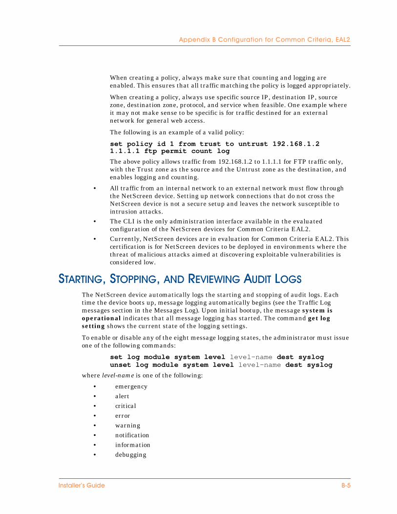
When creating a policy, always make sure that counting and logging are enabled. This ensures that all traffic matching the policy is logged appropriately.
When creating a policy, always use specific source IP, destination IP, source zone, destination zone, protocol, and service when feasible. One example where it may not make sense to be specific is for traffic destined for an external network for general web access.
The following is an example of a valid policy:
set policy id 1 from trust to untrust 192.168.1.2 1.1.1.1 ftp permit count log
The above policy allows traffic from 192.168.1.2 to 1.1.1.1 for FTP traffic only, with the Trust zone as the source and the Untrust zone as the destination, and enables logging and counting.
• All traffic from an internal network to an external network must flow through the NetScreen device. Setting up network connections that do not cross the NetScreen device is not a secure setup and leaves the network susceptible to intrusion attacks.
• The CLI is the only administration interface available in the evaluated configuration of the NetScreen devices for Common Criteria EAL2.
• Currently, NetScreen devices are in evaluation for Common Criteria EAL2. This certification is for NetScreen devices to be deployed in environments where the threat of malicious attacks aimed at discovering exploitable vulnerabilities is considered low.
�������1��� ����1����������������� ��The NetScreen device automatically logs the starting and stopping of audit logs. Each time the device boots up, message logging automatically begins (see the Traffic Log messages section in the Messages Log). Upon initial bootup, the message system is operational indicates that all message logging has started. The command get log setting shows the current state of the logging settings.
To enable or disable any of the eight message logging states, the administrator must issue one of the following commands:
set log module system level level-name dest syslogunset log module system level level-name dest syslog
where level-name is one of the following:
• emergency • alert • critical • error • warning • notification • information • debugging
������������ �� <,5
&%%��� #<���� ����� ������������� ��� �@3&�-
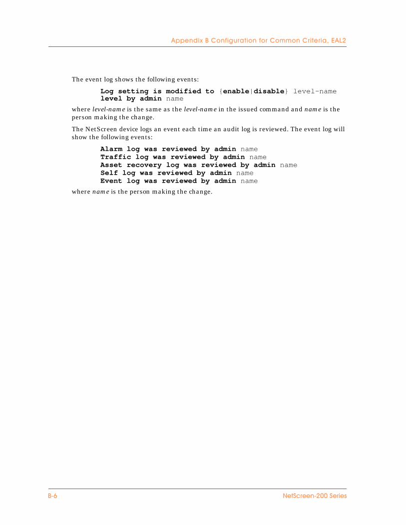
The event log shows the following events:
Log setting is modified to {enable|disable} level-name level by admin name
where level-name is the same as the level-name in the issued command and name is the person making the change.
The NetScreen device logs an event each time an audit log is reviewed. The event log will show the following events:
Alarm log was reviewed by admin nameTraffic log was reviewed by admin nameAsset recovery log was reviewed by admin nameSelf log was reviewed by admin nameEvent log was reviewed by admin name
where name is the person making the change.
<,6 ��!�����,-..!�� ��
����#
����#&asset recovery 27
<Back panel 6
�Cables
connections 19power 19RJ-45 connectors 17RJ45 connectors 5, 13twisted pair 13, 17
cablingnetwork interfaces 25power supply 21
changing login and password 23compact flash card slot 5Configuration
multiple devices 19connecting the power supply 11connecting, serial connection 26connecting, system to other devices 12Connectivity 12console
changing timeout 23, 25Console port 5console session, establishing 22console session, using a dialup connection 26
$DC power supply, wiring 12dialup connection 26
�guide organization v
(high availability 20high availability,
establishing an HA connection 20
�installation guidelines 10IP address
conflicts 19
�LEDs 6Link lights 6, 19Logging on 26login name
changing (CLI) 25login, changing 23
*management port, setting an IP address 23management session 26mounting, rear and front rack installation 11Multiple devices 19
NetScreen Publications ixNetScreen-204/208
connecting 19NetScreen-204/208, about 2
�password
changing (CLI) 25forgetting 27
password, changing 23port settings, viewing 23
��!�����,-..!�� ��
����#
Portsconsole 5ethernet 6
Powersupply 19
power suppliesDC, wiring 12
power supply, connecting to the system 11power supply, installing 11
4Rack 10, 19
mounting 10rack installation guidelines 10reset 27
�Transparent mode 16
�Ventilation 10viewing port settings 23
������������ ��