Embed Size (px)
Citation preview

Netbiter Argos
User Manual
For the Netbiter EasyConnect products
HMS Industrial Networks AB
Rev. 1.00
Post address: Box 4126 300 04 Halmstad SWEDEN
Visitor’s address: Stationsgatan 37 302 45 Halmstad SWEDEN
Telephone: + 46 35 17 29 00 Fax: + 46 35 17 29 09
E-mail: [email protected] Web: www.netbiter.com
>>> Distribucion: ER-Soft, S.A. www.er-soft.com [email protected] Tel: +34 916-408-408 <<<

Netbiter Argos User Manual
Rev. 1.00
HMS Industrial Networks AB
Page 2 (51)
History
Reversion Date Description Author
1.00 2012-03-02 First revision VIHA
Terminology
Netbiter Argos Data Center
The Netbiter Argos data center is a solution that collects and stores data from connected Systems. The Netbiter Argos contains various features such as alarm management, reporting capabilities and much more.
Netbiter Argos Account A Netbiter Argos Account is an user account from where you can manage and administrate connected systems.
Netbiter Argos Project Connected systems can be grouped into Netbiter Argos Projects in order to get a better management overview. Example: Systems belonging to a specific address, customer or similar.
System A System is the Netbiter Gateway and Devices put together as a unit. A System can consist of multiple Devices but only one Gateway.
Gateway A Gateway can be either an EasyConnect, webSCADA unit or a third-party product that is compatible with Netbiter Argos.
Device A Device is the equipment that is to be monitored and is connected to a Gateway. Examples of devices; diesel generator controller, UPS’s, energy meters or a PLC’s.

Netbiter Argos User Manual
Rev. 1.00
HMS Industrial Networks AB
Page 3 (51)
Table of content 1 Getting started ........................................................................................................... 5
1.1 Create a Netbiter Argos Account ......................................................................................... 5
1.2 Add a new System ............................................................................................................... 7
1.3 Activating a system .............................................................................................................. 8
1.3.1 Netbiter EC150 ............................................................................................................... 8
1.3.2 Netbiter EC220 ............................................................................................................... 9
1.3.3 Netbiter EC250 ............................................................................................................... 9
2 Basic Configure of the Netbiter System ..................................................................... 11
2.1 Add device ......................................................................................................................... 11
2.1.1 Modbus device ............................................................................................................. 11
2.1.2 Virtual device ................................................................................................................ 12
2.1.3 Virtual GPS device ........................................................................................................ 12
2.2 Add log parameter ............................................................................................................. 12
2.3 Add Visualization parameter ............................................................................................. 13
2.4 Add alarm parameter ........................................................................................................ 15
2.5 Gateway settings ............................................................................................................... 16
2.5.1 GPS ............................................................................................................................... 16
2.5.2 Modbus ........................................................................................................................ 16
2.6 Synchronize the configuration ........................................................................................... 17
2.7 Advanced configuration ..................................................................................................... 17
2.7.1 Connect Device Profiles ................................................................................................ 17
2.8 Server side alarm ............................................................................................................... 18
2.8.1 Offline alarm ................................................................................................................. 18
2.9 Positioning the remote system .......................................................................................... 18
3 Create a Dashboards ................................................................................................ 20
3.1 System Dashboards ........................................................................................................... 20
3.2 Profile Dashboards ............................................................................................................. 20
3.3 Dashboard properties ........................................................................................................ 21
3.4 Widgets .............................................................................................................................. 21
3.4.1 Add widgets .................................................................................................................. 22
3.4.2 Remove widget ............................................................................................................. 22
3.4.3 Rearrange widgets ........................................................................................................ 22

Netbiter Argos User Manual
Rev. 1.00
HMS Industrial Networks AB
Page 4 (51)
3.4.4 Value List widget .......................................................................................................... 22
3.4.5 Drawing widget ............................................................................................................ 23
3.4.6 Create a Drawing .......................................................................................................... 25
4 Subscriptions ............................................................................................................ 35
4.1.1 Add Subscription key .................................................................................................... 35
4.1.2 Assign a Subscription key ............................................................................................. 36
5 Users ........................................................................................................................ 37
5.1 List view ............................................................................................................................. 37
5.2 Project view ....................................................................................................................... 37
5.3 Add a new user .................................................................................................................. 37
5.3.1 User information .......................................................................................................... 38
5.3.2 User rights .................................................................................................................... 38
5.3.3 Alarm scheduling .......................................................................................................... 39
5.4 Edit a user .......................................................................................................................... 39
5.4.1 Changing password ...................................................................................................... 40
5.5 Lost password .................................................................................................................... 40
6 Profiles ..................................................................................................................... 41
6.1 Device Profile ..................................................................................................................... 41
6.1.1 Create a Device Profile ................................................................................................. 41
6.1.2 Edit Device Profile ........................................................................................................ 42
6.1.3 Copy Device Profile ...................................................................................................... 43
6.1.4 Remove Device Profile ................................................................................................. 43
6.2 Global profiles .................................................................................................................... 43
7 Device Templates ..................................................................................................... 44
7.1 Create a new Modbus device template ............................................................................ 44
7.2 Upload Template ............................................................................................................... 48
7.3 Edit ..................................................................................................................................... 49
7.3.1 Template ...................................................................................................................... 49
7.3.2 Group ............................................................................................................................ 49
7.3.3 Parameter ..................................................................................................................... 49
7.4 Export Template ................................................................................................................ 50
8 HMS Support ............................................................................................................ 51

Netbiter Argos User Manual
Rev. 1.00
HMS Industrial Networks AB
Page 5 (51)
1 Getting started
This section takes over after the User Guide for the individual product and describes the procedure for getting the first system up and running.
1.1 Create a Netbiter Argos Account
1. Open a web browser and navigate to https://www.netbiter.net.
2. Click the Create an account link in order to create a new account.
3. Fill in the account information in the form and store your Account name and password as these will be used when accessing the account. Fields marked with a red asterisk (*) are required for creating the account.
The Device ID and the Activation Code are provided in the Netbiter Argos information note supplied with the Netbiter gateway.

Netbiter Argos User Manual
Rev. 1.00
HMS Industrial Networks AB
Page 6 (51)
4. Accept the terms and conditions; this is done by marking the checkbox.
5. Click on the Register button.
6. As the account is created, an E-mail containing an activation link will be sent to the e-mail address provided in the account information. Open the e-mail received from Netbiter Argos in your e-mail client and click on the activation link.
7. Now it is possible to login to the account. Press the go to login button to go back to the Netbiter Argos login page.
8. Navigate to the Netbiter Argos login page, https://www.netbiter.net. Enter the User and Password for the account and then click the Log on button in order to login to the Netbiter Argos account.
9. When logged in the Gateway used for creating the account need to be activated, see section 1.3.

Netbiter Argos User Manual
Rev. 1.00
HMS Industrial Networks AB
Page 7 (51)
1.2 Add a new System
Adding new Systems to a Netbiter Argos Account is done under the Management tab.
1. Click Add system under the All systems menu.
2. Enter the System name.
3. Enter the Device ID and Activation code for the Netbiter gateway. The Device ID and the Activation Code are provided on the Netbiter Argos information note supplied with the Netbiter gateway.
4. Set to which Project the system should be placed in.
5. Sett the correct Time zone where the system will be installed.
6. Click the add button in order to add a system.
System name The name of the System which it will be referred to on Netbiter Argos
Device ID The identification number for the gateway, supplied with the gateway.
Activation code The “password” for activating the gateway, supplied with the gateway.
Project The Project that the system should be connected to.
Time zone The time zone that the system is located in.

Netbiter Argos User Manual
Rev. 1.00
HMS Industrial Networks AB
Page 8 (51)
1.3 Activating a system
1. Click on the Management menu.
2. Click on the All systems menu.
3. Click on the Inactive tab.
4. Choose a STANDARD Subscription for the system in the dropdown window.
5. This step is optional. By clicking the add subscription key button a Subscription key can be entered and added in the select subscription window.
1.3.1 Netbiter EC150
6. Click on the activate button in order to activate the Netbiter EC150 System.

Netbiter Argos User Manual
Rev. 1.00
HMS Industrial Networks AB
Page 9 (51)
1.3.2 Netbiter EC220
1.3.2.1 Netbiter SIM card
6. Make sure that the I have a Netbiter SIM-card option is chosen.
7. Enter the SIM-card mobile number for the Netbiter SIM that was provided in the SIM card envelope.
1.3.2.2 Custom or Standard SIM card
6. Make sure that the I have a custom or standard SIM-card option is chosen.
7. Enter the SIM-card mobile number for the SIM card. This information should be supplied with the SIM card, if not please contact your mobile operator.
8. Enter the APN for the SIM card. This information should be supplied with the SIM card, if not please contact your mobile operator. If an APN username and password is needed fill in that information.
1.3.3 Netbiter EC250
6. Click the activate button in order to activate the Netbiter EC250 System.
If the Netbiter EC250 is connecting using GPRS, Mobile network settings are needed.
1.3.3.1 Netbiter SIM card
7. Enter the SIM-card mobile number for the Netbiter SIM that was provided in the SIM card envelope.
8. Click the send button, in order to send down the Mobile network settings to the Netbiter EC250.

Netbiter Argos User Manual
Rev. 1.00
HMS Industrial Networks AB
Page 10 (51)
1.3.3.2 Custom or Standard SIM card
7. Make sure that the I have a custom or standard SIM-card option is chosen.
8. Enter the SIM-card mobile number for the SIM card. This information should be supplied with the SIM card, if not please contact your mobile operator.
9. Enter the APN for the SIM card. This information should be supplied with the SIM card, if not please contact your mobile operator. If an APN username and password is needed fill in that information.
10. Click the send button, in order to send down the Mobile network settings to the Netbiter EC250.

Netbiter Argos User Manual
Rev. 1.00
HMS Industrial Networks AB
Page 11 (51)
2 Basic Configure of the Netbiter System
To start the configuration, go to the Management menu and then to the System that is going to be configured and click on the Configuration tab.
2.1 Add device
A device is a unit that can be connected to the Netbiter gateway with for example Modbus and together with the Netbiter gateway form a Netbiter System.
1. Click on the add device button under the Device configuration tab.
2.1.1 Modbus device
2. Chose Modbus in the dropdown menu for the Device type.
3. Chose the Template for the device from the dropdown menu.
4. Chose the Device name that the device will be referred to as in the Netbiter Argos account.
5. Enter the Modbus Slave ID for the Modbus device.
6. If a Modbus TCP device is used enter the Modbus IP number for the device.
Device type The type of device that will be added
Template
The Device template used for this Remote device, see section 4
Device name The name that the device will be referred to as.
Modbus slave The Modbus Slave/ID for the device

Netbiter Argos User Manual
Rev. 1.00
HMS Industrial Networks AB
Page 12 (51)
Modbus IP If it is a Modbus TCP device, add the IP number for the device
Modbus port The port that the gateway will use for communication with Modbus TCP
2.1.2 Virtual device
A virtual device is the Netbiter gateway itself and is pre-loaded when the gateway is activated.
2.1.3 Virtual GPS device
In order to connect a GPS receiver to the System it needs to be added as a Virtual GPS.
Further settings is required, see section 2.5.
2.2 Add log parameter
Added log parameters can be displayed under the Historical data tab for the System presentation page or on a Dashboard. It will take up to an hour before the first logged data is sent up to the server automatically.
1. Click on the add log parameter button under the Logging tab.
2. Fill in the information on the Add log parameter screen.
Device The device that the parameter comes from
Group The template Group that the parameter comes from
Parameter The log parameter that is being added

Netbiter Argos User Manual
Rev. 1.00
HMS Industrial Networks AB
Page 13 (51)
Description Will be the name used on the logged data. As default the Description is the template parameter Name. By marking the checkbox on the right, the description can be changed.
Unit The unit for the parameter. Is as default the Unit stated in the template. By marking the checkbox on the right, the Unit can be changed or added if not available in the template.
Scaling Is used when the parameter value needs to be scaled before it is logged. The parameter will be divided with the scaling before logged. Ex. parameter value = 510, Scaling = 10 -> 51.0 will be logged
Offset Is used for adding a number to the scaled parameter value. Ex. Scaled parameter value = 51.0, Offset = 5.3, => 51.0+5.3=56.3 will be logged
Number of decimals
Determents how many decimals in the parameter that will be used for the logged of value.
Valid range A set parameter must be in this range in order to be set.
Enumeration For parameters that are of enumeration type in the template, the enumeration can be overridden by clicking the checkbox at the right of the row. The parameter value can be presented with the string definition for a value were the valus are separated by “;”. Ex. 1=ON; 0=OFF
Log interval The log interval determines the interval between two log points. Can be from 30sec up to 60min depending on subscription added to the System.
Log type Value - The parameter value are stored. Delta - The difference between the current point and the one before is stored. Ex. Point(i) – Point(i-1) is stored
3. Click Save and the Log parameter will be added; Cancel will close the window and discard all changes.
2.3 Add Visualization parameter
Visualization parameters are used for presenting parameter values on the overview page or on a Dashboard.
1. Click the add visualization parameter button under the Visualization tab.
Netbiter Argos User Manual
Rev. 1.00
HMS Industrial Networks AB
Page 14 (51)
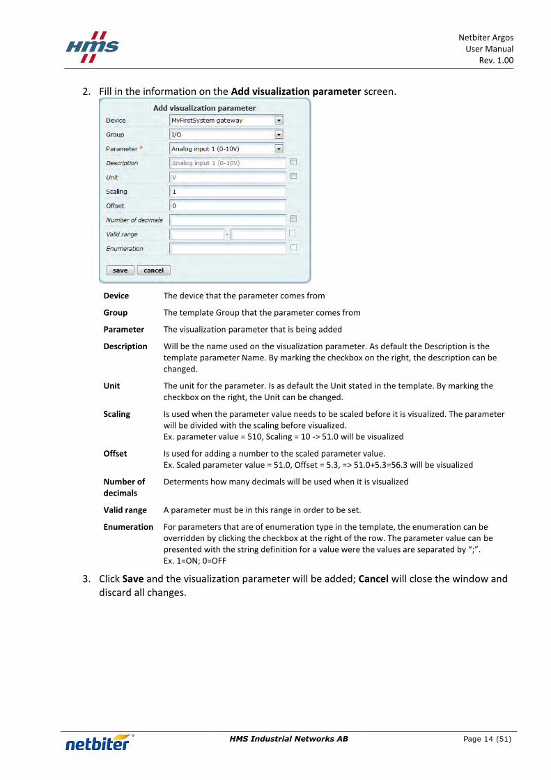
2. Fill in the information on the Add visualization parameter screen.
Device The device that the parameter comes from
Group The template Group that the parameter comes from
Parameter The visualization parameter that is being added
Description Will be the name used on the visualization parameter. As default the Description is the template parameter Name. By marking the checkbox on the right, the description can be changed.
Unit The unit for the parameter. Is as default the Unit stated in the template. By marking the checkbox on the right, the Unit can be changed.
Scaling Is used when the parameter value needs to be scaled before it is visualized. The parameter will be divided with the scaling before visualized. Ex. parameter value = 510, Scaling = 10 -> 51.0 will be visualized
Offset Is used for adding a number to the scaled parameter value. Ex. Scaled parameter value = 51.0, Offset = 5.3, => 51.0+5.3=56.3 will be visualized
Number of decimals
Determents how many decimals will be used when it is visualized
Valid range A parameter must be in this range in order to be set.
Enumeration For parameters that are of enumeration type in the template, the enumeration can be overridden by clicking the checkbox at the right of the row. The parameter value can be presented with the string definition for a value were the values are separated by “;”. Ex. 1=ON; 0=OFF
3. Click Save and the visualization parameter will be added; Cancel will close the window and discard all changes.

Netbiter Argos User Manual
Rev. 1.00
HMS Industrial Networks AB
Page 15 (51)
2.4 Add alarm parameter
The remote system can be configured to generate alarms when certain conditions are met.
1. Click the add alarm parameter button under the Alarms tab.
2. Fill in the information on the Add alarm setting screen.
Device The device that the parameter comes from
Group The template Group that the parameter comes from
Parameter The visualization parameter that is being added
Description Will be the name of the alarm. By clicking the button the Parameter name will be entered as Description
Trigger The trigger work together with value stated in the value field. Equal to – If the parameter is equal to the Value Not equal to - If the parameter is not equal to the Value Less than - If the parameter is less than the Value Greater than - If the parameter is greater than the Value Any bit - If any bit in the parameter is equal to the Value (0/1) Neither bit - If neither bit in the parameter is equal to the Value (0/1) All bit - If all bits in the parameter is equal to the Value (0/1) No response - Used to detect if a device has lost contact . The value is the number of consecutive time outs for communication with the device
Value The value used to fulfill the trigger condition.
Scaling Is used when the parameter value needs to be scaled before it the trigger comparison is made. The parameter will be divided with the scaling before comparison. Ex. parameter value = 510, Scaling = 10 -> 51.0 will be compared
Offset Is used for adding a number to the scaled parameter value. Ex. Scaled parameter value = 51.0, Offset = 5.3, => 51.0+5.3=56.3 will be compared
Class Used to divide alarms into different classes from 1 to 10. No further use implemented.
Severity Used to divide alarms into different severity levels. Indeterminate, Critical, Major, Minor, Warning that are displayed with different colors in the alarm list.

Netbiter Argos User Manual
Rev. 1.00
HMS Industrial Networks AB
Page 16 (51)
3. Clicking Save button and the alarm parameter will be added; Cancel will close the window and discard all changes.
2.5 Gateway settings
Under the Gateway settings the GPS and Modbus communication can be configured.
Only one variable can be set at the time, there for the set button next to the variable have to be pushed before moving to the next. If set is not pushed the Gateway will not get the configuration.
2.5.1 GPS
Enable Switch the D-sub connection of the Gateway into GPS mode.
Baud Rate The baud rate which the GPS receiver communicates with the Gateway.
Distance The distance the GPS position has to move before a new position is sent up to Netbiter Argos
2.5.2 Modbus
Physical The port on the Gateway used for the Modbus communication.
Baud Rate The baud rate which the Modbus port communicates with connected Modbus devices.
Party Number of parity bits with which the Modbus port communicates with connected Modbus devices.
Stop Bits The number of stop bits with which the Modbus port communicates with connected Modbus devices

Netbiter Argos User Manual
Rev. 1.00
HMS Industrial Networks AB
Page 17 (51)
2.6 Synchronize the configuration
The final step to finish the configuration is to download the configuration to the Gateway.
1. Press the button synchronize configuration.
2. The Gateway will reboot and reconnect to Netbiter Argos automatically; Note! This may take a few minutes.
2.7 Advanced configuration
The Advanced configuration menu is accessed by click on the Show Advanced Config Link under the Configuration tab
2.7.1 Connect Device Profiles
The advanced configuration allows you to assign Device Profiles to the System.
1. Click the connect device profile button under the Connect device profile tab.
2. Chose the Device you have added to your system to which you like to add a device profile.
3. Chose the Profile you like to add to the device.
Device Is the Device that is connected to the gateway and which the Device Profile should be connected towards.
Device profile Is the profile that will be connected towards the Device.
4. Click Save and the Profile will be assigned, and Cancel will close the window and discard all changes.
NOTE! The device needs to be added before a Device Profile can be connected, see section 2.1
For information about how to make a Profile, see section 4.
Netbiter Argos User Manual
Rev. 1.00
HMS Industrial Networks AB
Page 18 (51)
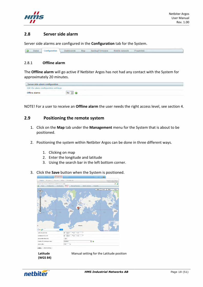
2.8 Server side alarm
Server side alarms are configured in the Configuration tab for the System.
2.8.1 Offline alarm
The Offline alarm will go active if Netbiter Argos has not had any contact with the System for approximately 20 minutes.
NOTE! For a user to receive an Offline alarm the user needs the right access level, see section 4.
2.9 Positioning the remote system
1. Click on the Map tab under the Management menu for the System that is about to be positioned.
2. Positioning the system within Netbiter Argos can be done in three different ways.
1. Clicking on map 2. Enter the longitude and latitude 3. Using the search bar in the left bottom corner.
3. Click the Save button when the System is positioned.
Latitude (WGS 84)
Manual setting for the Latitude position

Netbiter Argos User Manual
Rev. 1.00
HMS Industrial Networks AB
Page 19 (51)
Longitude (WGS 84)
Manual setting for the Longitude position
Get position from GPS
If a GPS is connected to the System, the osition can manually be retrieved by pressing the GPS button.
Enable GPS tracking on map
Enables the Tracking function, need to have a GPS receiver connected in order for this function to work.
Alarm radius The Alarm radius is used for setting the boundaries for the Geo Fencing function, this function need an GPS receiver connected.
The manual positioning service works without any GPS receiver.
Note! If connected to a GPS the device can automatically position itself on the map. GPS tracking on the map can be enabled to monitor movements of the device. An alarm can be triggered if the device is moved outside of the defined radius, also known as “Geo-fencing”.

Netbiter Argos User Manual
Rev. 1.00
HMS Industrial Networks AB
Page 20 (51)
3 Create a Dashboards
The dashboard is used to making a customized presentation page for the system. There are two different types of Dashboards:
System Dashboard – A Dashboard made for a single system
Profile Dashboard – A Dashboard that can be used for multiple Systems using the Profile it is assigned to.
3.1 System Dashboards
1. Click on the Dashboard tab under the Management menu for the System.
2. Click the add button under the Dashboard tab
3. A new dashboard for the system is created and ready to be configured, see section 3.4.
3.2 Profile Dashboards
1. Click on the All dashboards menu under the Management menu.
2. Click on the Add dashboard tab.
3. Fill in the information on the Add dashboard screen, and then click the save button.
Dashboard name
The Name of the Dashboard which will be displayed in the menue.
Access level Determines how will have rights to access the dashboard, only the Admin or also the users.

Netbiter Argos User Manual
Rev. 1.00
HMS Industrial Networks AB
Page 21 (51)
Sort priority Determines the order of the dashboards if there are several. Lowest value will be displayed first. Possible to set from 1 to 99.
Dashboard type Determines if it is a System or Profile dashboard.
Profile Determines to what Profile the dashboard should be connected towards. The Profile need to be created before a device can be added.
3.3 Dashboard properties
The properties for the dashboard can be changed by pressing the edit button.
Dashboard name The Name of the Dashboard which will be displayed in the menu.
Access level Determines who will have rights to access the dashboard, only the Admin or also the users.
Sort priority Determines the order of the dashboards. Lowest value will be placed farthest to the right. Possible to set from 1 to 99.
Press the OK button in order to save the new properties.
3.4 Widgets
The widgets are building blocks used to building up the dashboard.
The available widgets are:
Live values o Value List widget o Drawing widget
Logged values o Latest logged widget o Log Graph widget
Alarms o Alarm List widget

Netbiter Argos User Manual
Rev. 1.00
HMS Industrial Networks AB
Page 22 (51)
3.4.1 Add widgets
1. Go to the the dashboard the new widget is intended to be placed in.
2. Click on the Widget in the Widgets menu on the right side, it will be added as a block on the right side.
3. As soon as the widget is added, the dashboard is automatic saved.
3.4.2 Remove widget
1. Click on the delete button on the widget in order to remove it.
3.4.3 Rearrange widgets
The order of the widgets can be rearranged by dragging and dropping them in the preferred order.
3.4.4 Value List widget
1. Click the edit button on the Live value list widget and the Settings window will apear.
Title The Name of the widget which will be displayed in the dashboard.
2. Enter the title of the widget.

Netbiter Argos User Manual
Rev. 1.00
HMS Industrial Networks AB
Page 23 (51)
3. Click the add button
4. Select a parameter that will be displayed on the dashboard by clicking on it. It is parameters that are configured as vizualisation or log parameter that are possible to choose from, see section 2 in order to add new.
5. Click OK and the Widget will be configured; Cancel will close the window and discard all changes.
3.4.5 Drawing widget The drawing tool is a graphical web application that can be used to create dynamic, customized and interactive visualizations of your remote system. You can add images, objects, parameters and alarms to be visualized on the dashboard.
3.4.5.1 Drawing Tools
To access the Drawing click the Edit button on the on the drawing widget.
Netbiter Argos User Manual
Rev. 1.00
HMS Industrial Networks AB
Page 24 (51)
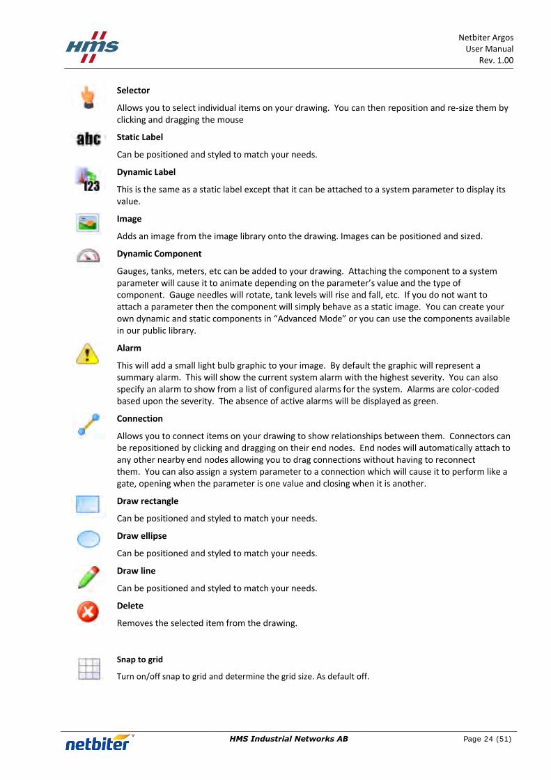
Selector
Allows you to select individual items on your drawing. You can then reposition and re-size them by clicking and dragging the mouse
Static Label
Can be positioned and styled to match your needs.
Dynamic Label
This is the same as a static label except that it can be attached to a system parameter to display its value.
Image
Adds an image from the image library onto the drawing. Images can be positioned and sized.
Dynamic Component
Gauges, tanks, meters, etc can be added to your drawing. Attaching the component to a system parameter will cause it to animate depending on the parameter’s value and the type of component. Gauge needles will rotate, tank levels will rise and fall, etc. If you do not want to attach a parameter then the component will simply behave as a static image. You can create your own dynamic and static components in “Advanced Mode” or you can use the components available in our public library.
Alarm
This will add a small light bulb graphic to your image. By default the graphic will represent a summary alarm. This will show the current system alarm with the highest severity. You can also specify an alarm to show from a list of configured alarms for the system. Alarms are color-coded based upon the severity. The absence of active alarms will be displayed as green.
Connection
Allows you to connect items on your drawing to show relationships between them. Connectors can be repositioned by clicking and dragging on their end nodes. End nodes will automatically attach to any other nearby end nodes allowing you to drag connections without having to reconnect them. You can also assign a system parameter to a connection which will cause it to perform like a gate, opening when the parameter is one value and closing when it is another.
Draw rectangle
Can be positioned and styled to match your needs.
Draw ellipse
Can be positioned and styled to match your needs.
Draw line
Can be positioned and styled to match your needs.
Delete
Removes the selected item from the drawing.
Snap to grid
Turn on/off snap to grid and determine the grid size. As default off.

Netbiter Argos User Manual
Rev. 1.00
HMS Industrial Networks AB
Page 25 (51)
Drawing Settings
Change the name of the drawing and the height of the drawing area.
Copy object
Copy an existing object on the drawing.
Send to back
All objects on the Drawing are on their own layer, by clicking the send to back button it will move the object farthest back. This can result in that another object can be placed in front of it.
Send to front
All objects on the Drawing are on their own layer, by clicking the send to front button it will move the object to the front. This can result in that another object can be placed behind of it.
3.4.6 Create a Drawing
The Label, Image, component and alarm -objects are added to the drawing by selecting the preferred object and then click on the drawing, the dray and connection - objects are added by pressing down the left mouse button and then move the mouse, when the object has the preferred size let go of the mouse button.
The objects in the drawing tool are edited on their individual properties window, which is accessed by double clicking on the object. When the Property window is open it is just to click on another object in order to see its properties.
3.4.6.1 Static Label
When a Static label is added to the drawing, open the properties window. Fill in the preferred properties, the change will be done directly. When finished press the close button or move to another drawing tool.
position The position of the tool on the drawing
size The size of the tool
color The text color can be set by clicking the colored rectangle

Netbiter Argos User Manual
Rev. 1.00
HMS Industrial Networks AB
Page 26 (51)
After selecting color, press OK
opacity Determines the transparency of the text, from 0 to 1 were 1 is solid.
text The text displayed on the drawing
font The text font for the object
font-pt The text size
Makes the text bold or/and italics
Determines the text position within the tool; left, center or right positioning
3.4.6.2 Dynamic Label
When a Dynamic label is added to the drawing, open the properties window. Fill in the preferred properties, the change will be done directly. When finished press the close button or move to another drawing tool.
position The position of the object on the drawing
size The size of the object
color The text color can be set by clicking the colored rectangle
After selecting color, press OK
opacity Determines the transparency of the text, from 0 to 1 were 1 is solid.
text The text displayed on the drawing. When a parameter is added the default formation is “<parameter label>: $val$” where “$val$” is the parameter value. THE “$val$” part can be placed anywhere within the string.
font The text font for the ogject

Netbiter Argos User Manual
Rev. 1.00
HMS Industrial Networks AB
Page 27 (51)
font-pt The text size for the object
Makes the text bold or/and italics
Determines the text position within the object; left, center or right positioning
3.4.6.3 Image
When the image is added the open image from server will appear.
The right side contains the Netbiter Image library and the left your Image library. Images displayed on the drawing must be located on your Image library. Adding Images to your Image library can be done in two ways:
1. From Netbiter Image library: By choosing an image in the Netbiter Image library and click on it you will see a preview of the image and by clicking the green arrow below the image will be moved to your library.
2. Upload from your Computer: By clicking on the image icon a file transfer window will appear that allow you to browse your computer and decide what image you like to upload to your Image library. Supported formats are, jpeg, gif, png.

Netbiter Argos User Manual
Rev. 1.00
HMS Industrial Networks AB
Page 28 (51)
When the image is located on your Image library it can be chosen to be added onto the drawing. By clicking on the image in your Image library and then click OK in the lower right corner the image will be added to your drawing.
By double click on image the properties window will appear.
position The position of the object on the drawing
size The size of the object
opacity Determines the transparency of the text, from 0 to 1 were 1 is solid.
parameter Connect the image to a parameter.
If a parameter is connected to the image the image can change depending on the parameter value
Default The default image that will be displayed. The image can be changed by double click on the image icon, the Image library will appear.
Unknown If the parameter is unknown (cannot be read) the unknown image will be displayed on the drawing. The image can be changed by double click on the small question icon, the Image library will appear.
Value Determines the image that will be displayed on the drawing if the set condition is fulfilled.
If parameter value is: = Equal to < Smaller <= Smaller or Equal to > Larger >= Larger or Equal to than the set value, the default image will be changed to the image displayed as an icon next to the condition. The image can be changed by double click on the icon, the Image library will appear.

Netbiter Argos User Manual
Rev. 1.00
HMS Industrial Networks AB
Page 29 (51)
When a writable parameter is connected to the image and the writable checkbox is set, the on click set value to: value will be written to the parameter connected to the image.
If you want to delete the Image this is done by clicking on the image in your Image library and the click on the delete button.
3.4.6.4 Component
When the Component is added the add drawing from server will appear.

Netbiter Argos User Manual
Rev. 1.00
HMS Industrial Networks AB
Page 30 (51)
Under the Public Library on the right there is a set of pre made Components that can be added to the drawing.
When a component is clicked it will be previewed in the middle window.
In order to add the Component click the OK button in the bottom left corner.
By double click on image the properties window will appear.
position The position of the object on the drawing
size The size of the object
color The text color can be set by clicking the colored rectangle
After selecting color, press OK
parameter The Parameter connected to the object
min value The minimum value displayed by the object.
max value The maximum value displayed by the object
There are different types of components to choose from in the Public Library.
Gauges Graduated Tanks Temperature Bars

Netbiter Argos User Manual
Rev. 1.00
HMS Industrial Networks AB
Page 31 (51)
3.4.6.5 Alarm
In order to add an alarm indicator, click on the add alarm tool and on the position where the alarm indicator should be placed.
As default it will indicate the alarm with the highest severity level. The alarm indicator will have different colors depending on the severity.
By double click on the alarm indicator the properties window will appear.
position The position of the object on the drawing
size The size of the object
opacity Determines the transparency of the text, from 0 to 1 were 1 is solid.
alarm As default Summary and if chooses set to a specific alarm.
In order to choose a specific alarm that should be indicated, click on the button on the properties window and all configured alarms will be listed. Click on the alarm that should be assigned and then click the OK button.
3.4.6.6 Connections
In order to add a Connection click on the connection tool and press the left mouse button on the start and let it go where the connection should end. Once the Connection is added, the start and end can be moved by dragging the end points. If there are two or more connections the end points can be connected by dragging them together.
By double click on the Connection a properties window will appear.

Netbiter Argos User Manual
Rev. 1.00
HMS Industrial Networks AB
Page 32 (51)
position The position of the component on the drawing
size The size of the component
opacity Determines the transparency of the text, from 0 to 1 were 1 is solid.
parameter The Parameter connected to the Connection.
By clicking on the button on the properties window, a parameter can be assigned to the Connection. The open if=: parameter determines the condition that must be met in order for the connection should open
Closed Open
3.4.6.7 Draw Rectangle
In order to add a rectangle click on the Draw Rectangle tool and press the left mouse button on the start corner and let it go where the opposite corner of the rectangle should end. Ones the rectangle is added, the size can be change by grabbing the edges of the rectangle and drag it.
By double click on the added rectangle a properties window will appear.
position The position of the object on the drawing
Netbiter Argos User Manual
Rev. 1.00
HMS Industrial Networks AB
Page 33 (51)
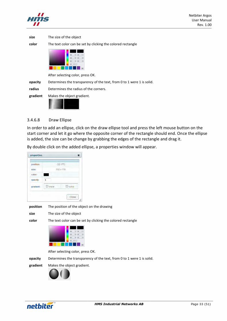
size The size of the object
color The text color can be set by clicking the colored rectangle
After selecting color, press OK.
opacity Determines the transparency of the text, from 0 to 1 were 1 is solid.
radius Determines the radius of the corners.
gradient Makes the object gradient.
3.4.6.8 Draw Ellipse
In order to add an ellipse, click on the draw ellipse tool and press the left mouse button on the start corner and let it go where the opposite corner of the rectangle should end. Once the ellipse is added, the size can be change by grabbing the edges of the rectangle and drag it.
By double click on the added ellipse, a properties window will appear.
position The position of the object on the drawing
size The size of the object
color The text color can be set by clicking the colored rectangle
After selecting color, press OK.
opacity Determines the transparency of the text, from 0 to 1 were 1 is solid.
gradient Makes the object gradient.

Netbiter Argos User Manual
Rev. 1.00
HMS Industrial Networks AB
Page 34 (51)
3.4.6.9 Draw line
In order to draw a line, click on the draw line tool and press the left mouse button on the start of the line and let it go where the line should end. Once the line is added, the size cannot be changed.
By double click on the added line, a properties window will appear.
position The position of the object on the drawing
size The size of the object
color The text color can be set by clicking the colored rectangle
After selecting color, press OK.
opacity Determines the transparency of the text, from 0 to 1 were 1 is solid.
radius Determines the radius of the corners.
gradient Makes the object gradient.
3.4.6.10 Delete object
By clicking on an object in the drawing and then the Delete object tool it will be removed from the drawing.

Netbiter Argos User Manual
Rev. 1.00
HMS Industrial Networks AB
Page 35 (51)
4 Subscriptions
Subscriptions are managed under Account->Licensing->Subscription.
All Subscription key added to the account are listed with information about the level of subscription and how many systems that can use the Subscription.
All Systems in the account are listed and displayed with Subscription Level and when it will expire.
Name The Remote system name
Device ID The Remote gateways Device ID, that was supplied with the Remote gateway.
Project The project which the Remote system belongs to.
Level The subscription key level for the system.
Activated Displayes if the Remote system is active to be used in this account.
Expiration date The subscription key expiration date. The background is color coded as following; Expired - Less than three months left - More than three months left.
Select Check the Remote systems to which a subscription key will be deployed.
4.1.1 Add Subscription key
Adding a new Subscription key is done by clicking on the “add subscription key” button and enter the Subscription key.
When the Subscription key is activated it is placed in the Subscription key list.
Subscription key The subscription key for this row.
Order ref The order reference entered when the subscription key was bought.
Information Describes what is included in this subscription key (i.e. period, number of system that is valid for this key).
Used Number of used keys / total number of keys, which will show how many subscription that is available for this key.

Netbiter Argos User Manual
Rev. 1.00
HMS Industrial Networks AB
Page 36 (51)
Add date The date when the key were activated.
Select Click this to mark that this subscription key will be used to deploy it to a Remote system.
4.1.2 Assign a Subscription key
1. Select a subscription key to use, click Select for the preferred Subscription key 2. Mark the check box for the Remote systems that will have the subscription deployed to it 3. Click the use subscription key button to deploy the key to the selected Remote systems.

Netbiter Argos User Manual
Rev. 1.00
HMS Industrial Networks AB
Page 37 (51)
5 Users
5.1 List view
All available users for the account are listed under Account->Users->All users.
5.2 Project view
The users that have access to a specific project can be viewed under Account->Users->Users by project.
Project access Determines if the user has access to the project
Read data Determines if the user have access to read data from the system
Write data Determines if the user have access to write data to the system
Ack alarms Determines if the user have access to acknowledge alarms.
Alarms Determines if the user have access to receive alarms.
Offline alarms Determines if the user have access to receive Offline alarms, need to have Alarm access in order to receive this alarms.
GPS alarm Determines if the user have access to receive GPS alarms, need to have Alarm premises in order to receive this alarms.
Alarm via SMS Determines if the user have access to receive alarms via SMS.
Means that the user has access.
Means that the user has no access.
Means that the function is not available.
5.3 Add a new user
Adding new users is done under Account->Users->Add user. It consists of three parts
User information
Access level
Alarm Scheduling

Netbiter Argos User Manual
Rev. 1.00
HMS Industrial Networks AB
Page 38 (51)
5.3.1 User information
In order to add a new user, information need to be filled in. Information marked with * is required.
5.3.2 User rights
Under User rights the access that the user has for Projects in the Account is setup.
Project access Determines if the user has access to the project
Read data Determines if the user have access to read data from the system
Write data Determines if the user have access to write data to the system
Ack alarms Determines if the user have access to acknowledge alarms.
Alarms Determines if the user have access to receive alarms.
Offline alarms Determines if the user have access to receive Offline alarms, need to have Alarm access in order to receive this alarms.
GPS alarm Determines if the user have access to receive GPS alarms, need to have Alarm premises in order to receive this alarms.
Alarm via SMS Determines if the user have access to receive alarms via SMS.

Netbiter Argos User Manual
Rev. 1.00
HMS Industrial Networks AB
Page 39 (51)
5.3.3 Alarm scheduling
This section makes it possible to decide when the user will get e-mail or SMS. This is done to make selection in the schedule, one for e-mail, and one for SMS.
The schedule can be marked in periods of 30 minutes, using the mouse. Areas marked with green colors will send messages, periods with grey color indicates times when no message is send.
Click the mouse on the schedule to change the color. If you click the mouse button and drag the pointer the schedule can be "painted".
Under the schedule there is a selection to override the settings. If set to anything but N/A all messages with this severity set, or higher will be sent despite the scheduled time.
5.4 Edit a user
In order to edit an existing user
1. Click on the User name in the List view or Project view to enter the User overview.
2. Click the Edit user link.
3. The edit user page is divided into three parts:
User information
User rights
Alarm Scheduling
See section 5.3 for more details.
Netbiter Argos User Manual
Rev. 1.00
HMS Industrial Networks AB
Page 40 (51)
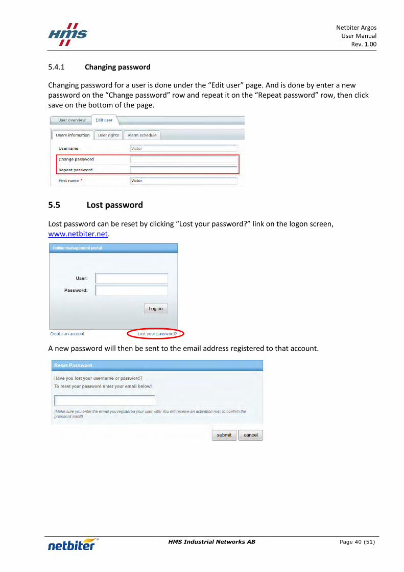
5.4.1 Changing password
Changing password for a user is done under the “Edit user” page. And is done by enter a new password on the “Change password” row and repeat it on the “Repeat password” row, then click save on the bottom of the page.
5.5 Lost password
Lost password can be reset by clicking “Lost your password?” link on the logon screen, www.netbiter.net.
A new password will then be sent to the email address registered to that account.

Netbiter Argos User Manual
Rev. 1.00
HMS Industrial Networks AB
Page 41 (51)
6 Profiles
Profiles are handled in the Profile menu under the Management menu.
There are two types of profiles:
Device Profiles – A Profile created and possible to edit by the user
Global Profiles – A predefine Profile that is not possible to edit by the user
Both types of Profiles can consist of two parts:
1. Parameter configuration a. Logging parameters b. Visualization parameters c. Alarm parameters
2. Dashboard
6.1 Device Profile
6.1.1 Create a Device Profile
1. Click on the Add profile tab under the Profiles menu.
2. Enter the Profile name.
3. Choose the Profile type to use: a. Virtual type is used when the Profile is being created for a Netbiter gateway. b. Virtual GPS type is used when the Profile is being created for a GPS receiver. c. Modbus type is used when the Profile is being created for a Modbus device.

Netbiter Argos User Manual
Rev. 1.00
HMS Industrial Networks AB
Page 42 (51)
4. Choose the template to be used by the profile. See section 7 for information about how to create or upload a device Profile.
5. Click on the save button to proceed.
6. The Edit profile screen will appear.
7. Click on the add button in order to connect additional Templates to the Device Profile.
8. To add Logging, Visualization & Alarm to the Device Profile, se section 2.2, 2.3 and 0.
9. The Device profile is automatically saved during the configuration.
6.1.2 Edit Device Profile
1. Click on the Profiles tab under the Management menu.
2. Click on the Edit link on the row of the Device Template that should be edited.
3. The Edit profile screen will appear.
4. Change the Profile name by edit the existing name and then click the save button.
5. Click on the add button in order to connect additional Templates to the Device Profile.
6. To add Logging, Visualization & Alarm to the Device Profile, se section 2.2, 2.3 and 0.
7. The Device profile is automatically saved during the configuration.

Netbiter Argos User Manual
Rev. 1.00
HMS Industrial Networks AB
Page 43 (51)
6.1.3 Copy Device Profile
1. Click on the Profiles tab under the Management menu.
2. Click on the Copy link on the row of the Device Template that should be copied.
3. The Edit profile screen will appear with an exact copy of the original Device Profile. The default Profile name is “Copy” followed with the original Profile name.
4. Se section 6.1.2 for information about how to editing the Device Profile.
6.1.4 Remove Device Profile
1. Click on the Profiles tab under the Management menu.
2. Make sure that the Device Profile is not used by any Systems in the Account before it can be removed in a safe way.
3. Click on the Remove link on the row of the Device Template that should be copied.
6.2 Global profiles
A Global Profile is a fixed Profile that is not possible to edit.
The Global Profile can be used in two ways:
1. Added as instructed in section 2.7.1
2. Copied to the Account and becomes a Device Profile, the drawback is that if a Dashboard is connected it will be lost, on the other hand the Parameter configuration can be changed, see section 6.1.1.

Netbiter Argos User Manual
Rev. 1.00
HMS Industrial Networks AB
Page 44 (51)
7 Device Templates
A Device Template is describing the Modbus parameters for a remote device. It contains information about the available Modbus registers and their data types with scaling and offset predefined. Different ways to display the parameters can also be determined in the Device Template, for example Enumerations and read/write access.
7.1 Create a new Modbus device template
1. Click on the Templates menu under the Management menu.
2. Click the add template button.
3. Enter a Name for the Template.
4. Click on the save button in order to create the new Template; Cancel will close the window and discard all changes.
The parameters in the Template are divided into groups, as default there are a group called Default group that only will be visible when the Template is used if a parameter is added to it.
5. Click on the Add group link in order to add a new group to the template.
6. Enter a Name for the group.
7. Click on the save button.

Netbiter Argos User Manual
Rev. 1.00
HMS Industrial Networks AB
Page 45 (51)
8. Click on the Add parameter link in order to add a new parameter to the template.
9. Fill in the information on the Add parameter screen.
Name The name for this parameter
Unit The Unit for the parameter
Register Type Defines the Modbus register type (Holding, Input, Coil, Discrete input).To set Read or Write for this address see Presentation.
Address The Modbus register address to Read/Write. To enter a hex value use 0x as a prefix; (D6 hex -> 0xD6)
Datatype Defines the datatype of the Modbus register(s). Can be one of the following:
16 bits value with sign – 16-bit positive or negative value
16 bit value - 16-bit positive value
32 bits value with sign – 32-bit value, with sign. Most significant word (register) on low address.
32 bit value – 32-bit positive value. Most significant word (register) on low address.
Swapped 32 bits value with sign – 32-bit value, with sign. Most significant word (register) on high address.

Netbiter Argos User Manual
Rev. 1.00
HMS Industrial Networks AB
Page 46 (51)
Swapped 32 bit value – 32-bit positive value. Most significant word (register) on high address.
Floating point – 32-bit floating point. (IEEE-754) Most significant word (register) on
low address.
Swapped floating point – 32-bit floating point. (IEEE-754) Most significant word (register) on high address.
Double precision floating point – 64-bit floating point. (IEEE-754) Most significant word (register) on low address.
Swapped double precision floating point – 64-bit floating point. (IEEE-754) Most significant word (register) on high address.
Hi 8 bits value with sign – Show the high byte of a 16 bit register with sign. When writing this value it will read the 16 bit register, mask it with this value and write it back.
Lo 8 bits value with sign – Show the low byte of a 16 bit register with sign. When writing this value it will read the 16 bit register, mask it with this value and write it back.
Hi 8 bits value – Show the high byte of a 16 bit register. When writing this value it will read the 16 bit register, mask it with this value and write it back.
Lo 8 bits value – Show the low byte of a 16 bit register. When writing this value it will read the 16 bit register, mask it with this value and write it back.
Scaling The Modbus register value will be divided by the scale value before presented on the page, or multiplied before value is written to a slave device.
Examples: Modbus register value = 510, Scale value = 10 -> 51.0 will be viewed on page Modbus register value = 5118, Scale value = 100 -> 51.18 will be viewed on page Modbus register value = 1, Scale value = 0.1 -> 10 will be viewed on page Modbus register value = 2, Scale value = -1 -> -2 will be viewed on page Page input = 127.5 Scale value = 10 -> 1275 will be written to Modbus register
Offset The Modbus register value will be subtracted with the offset value before it is presented on the page, logged or compared with for alarm. If scaling is also in use it is done before the offset is subtracted. The Offset value will be added to the value before value is written to a Modbus slave device. If scaling is also in use it is done after the offset is added.
Examples: A register value of 5 and an offset of 2 -> 3 will be shown on the page.

Netbiter Argos User Manual
Rev. 1.00
HMS Industrial Networks AB
Page 47 (51)
Mask Is used to mask out specific bits from the Modbus register, on the page the value is
presented in binary. The Modbus register will be masked (logic and) and shifted to the right before the value is presented on the page, logged or compared with for alarm.
Examples: Modbus register value = 214 (D6 hex), Mask = 240 (F0 hex) -> 208 (D0 hex) -> the value is bit shifted and will be shown on page as 13 (D hex). To enter a hex value use 0x as a prefix; (D6 hex -> 0xD6)
Presentation Defines how a value will be represented on a page. Following presentation can be set:
Show as value – Show as value will read from the address and present the result at the page.
Read/Write value – Read/Write reads the value from the address and present it. There will be a set button next to the value at the page which makes it possible to write to the address.
Write only – This value can only be written and not be read.
Show with enumeration – Show with enumeration will read the value from the address and present it with the corresponding enum string, see Enum.
Read/Write value with enumeration – Read/Write value with enumeration will read the value from the address and present it with the corresponding enum string. There will be a drop down next to the value at the page where available enum strings will be selectable. A selected value will be written to the address. See Enum for more help.
Write only value with enumeration – The selected value will be written to the address. See Enumeration for more help.
Enumeration The enumeration variables is defined in the following format [number]=[string]. Each enum is separated by a semi colon ‘;’ with no blank spaces. Default can be set for Show with enumeration for all values not defined.
Examples: 0=Off;1=On 0=Sunday;1=Monday;2=Tuesday;3=Wednesday;4=Thursday;5=Friday;6=Saturday 0=Weekend;6=Weekend;Default=Workday
Number of decimals
Defines the number of decimals to use for this parameter.
Valid range Defines the maximum and minimum for a write parameter. If a user tries to enter a value
outside the range a warning message will appear. If used in combination with scaling, it is the scaled value that should be used.
10. Click on the save button in order to add the new parameter to the Template; Cancel will close the window and discard all changes.
11. Repeat step 8 to 10 until all parameters for the device is added to the Template.
12. Click on the Clone link on the line of the parameter it will be duplicated, then by clicking the Edit link it can be modified. This may save time in the construction of the Template

Netbiter Argos User Manual
Rev. 1.00
HMS Industrial Networks AB
Page 48 (51)
7.2 Upload Template
On the Netbiter Argos Support web page, www.support.netbiter.com, there are a wide range of premade Templates to be downloaded.
They are accessed by clicking on the Device Template button.
Example of template categories:
Genset
I/O nodes
Energy meters
Power monitoring
UPS
PLC
etc.
1. Click on the Templates menu under the Management menu.
2. Click the upload template button.
3. Click on the Browse button and choose the Template file that is about to be uploaded.
4. Click on the upload template button.

Netbiter Argos User Manual
Rev. 1.00
HMS Industrial Networks AB
Page 49 (51)
7.3 Edit
7.3.1 Template
1. Click on the Edit link on the line of the Template that is going to be edit.
2. Change the Name
3. Click on the save button
7.3.2 Group
1. Click on the Edit link on the line of the Group that is going to be edit.
2. Change the Name
3. Click on the save button
7.3.3 Parameter
1. Click on the Edit link on the line of the Parameter that is going to be edit.
2. The Edit parameter screen will appear; se section 7.1, step 9 for further information.
3. Click on the save button after the parameter is edited.

Netbiter Argos User Manual
Rev. 1.00
HMS Industrial Networks AB
Page 50 (51)
7.4 Export Template
1. Click on the Export link on the line of the Template that is going to be exported.
2. Click on the yes button in order to proceed with the export.
3. Click on the Test Template.xml link, it will be the name of the Template.
4. The look of this screen will be different depending on the web browser, choose if you like to open the file or save it to the hard drive of your computer.
5. Click the OK button to finalize the export of the Device Template

Netbiter Argos User Manual
Rev. 1.00
HMS Industrial Networks AB
Page 51 (51)
8 HMS Support
The support is accessed from the Netbiter Support web page, and is found at www.support.netbiter.com.
1. Click on the Request Support button.
2. Fill in as much information you can about your problem. Fields marked with a red asterisk (*) are required.
3. Click on the Submit button.