Embed Size (px)
Citation preview
Technical Report
NetApp HCI Network Setup Guide Version 1.2
Aaron Patten, NetApp
April 2018 | TR-4679
2 NetApp HCI Network Setup Guide © 2018 NetApp, Inc. All rights reserved. © 2016 NetApp, Inc. All rights reserved.
TABLE OF CONTENTS
1 Introduction ................................................................................................................................. 4
2 Hardware ..................................................................................................................................... 4
2.1 Node and Chassis Layout .................................................................................................................... 4
2.2 Node Types .......................................................................................................................................... 4
3 Physical Cabling ......................................................................................................................... 5
3.1 Detailed Physical NIC Layout ............................................................................................................... 6
4 Switch Configuration.................................................................................................................. 6
4.1 Network Overview ................................................................................................................................ 7
4.2 VPC ..................................................................................................................................................... 8
4.3 Jumbo Frames ..................................................................................................................................... 8
4.4 Switch Configuration for Storage Nodes .............................................................................................. 8
4.5 Switch Configuration for Compute Nodes .......................................................................................... 11
5 Deploying NetApp HCI Using NetApp Deployment Engine .................................................. 16
6 Network After NetApp HCI Deployment ................................................................................. 16
6.1 Storage Node Physical-to-Logical Port Map ...................................................................................... 16
6.2 vCenter Network Switch Options ....................................................................................................... 17
Where to Find Additional Information .......................................................................................... 22
LIST OF TABLES
Table 1) Compute nodes. ........................................................................................................................................ 5
Table 2) Storage nodes. .......................................................................................................................................... 5
Table 3) Node network ports. .................................................................................................................................. 6
Table 4) Storage node switch configuration example. ........................................................................................... 10
Table 5) Shared vMotion configuration example. .................................................................................................. 15
Table 6) Dedicated vMotion configuration example. .............................................................................................. 15
LIST OF FIGURES
Figure 1) HCI chassis. ............................................................................................................................................. 4
Figure 2) Network overview. .................................................................................................................................... 7
Figure 3) Storage node network connections. ......................................................................................................... 8
Figure 4) Storage node VLAN map. ........................................................................................................................ 9
Figure 5) Compute node network connections. ..................................................................................................... 11
Figure 6) Dedicated vMotion VLAN. ...................................................................................................................... 12
Figure 7) Compute node shared vMotion VLAN map. ........................................................................................... 13
Figure 8) Compute node dedicated vMotion VLAN map. ...................................................................................... 14
Figure 9) Storage node physical-to-logical port map. ............................................................................................ 16

3 NetApp HCI Network Setup Guide © 2018 NetApp, Inc. All rights reserved. © 2016 NetApp, Inc. All rights reserved.
Figure 10) Compute node physical to-logical port map (VSS). .............................................................................. 17
Figure 11) VMkernel binding. ................................................................................................................................ 18
Figure 12) VDS uplink names. ............................................................................................................................... 19
Figure 13) Compute node physical-to-logical port map (VDS). ............................................................................. 20
Figure 14) Management port groups: vmnic2/vmnic3. .......................................................................................... 21
Figure 15) vMotion and VM_Network: vmnic0/vmnic4. ......................................................................................... 21
Figure 16) iSCSI-A: vmnic5. .................................................................................................................................. 21
Figure 17) iSCSI-B: vmnic1. .................................................................................................................................. 22
4 NetApp HCI Network Setup Guide © 2018 NetApp, Inc. All rights reserved. © 2016 NetApp, Inc. All rights reserved.
1 Introduction
This document describes the steps required to configure networking for the NetApp® HCI system,
including network cabling, network switch configuration, and other network resources. This document
assumes that:
• You have completed the NetApp HCI prerequisites checklist.
• You have racked all HCI chassis and installed all NetApp HCI nodes.
• You have not yet deployed the NetApp HCI system software using the NetApp Deployment Engine (NDE).
For information about system prerequisites or your NetApp system in general, see NetApp
Documentation: Product Library A-Z.
Note: This document includes some configuration examples from Cisco series switches. See the documentation from your switch vendor for the exact syntax for your switch.
2 Hardware
The NetApp HCI system comes in a 2U chassis containing up to four independent nodes. In a single
chassis, you can install the compute nodes and storage nodes in any order.
The smallest configuration includes two chassis containing the following components:
• Two compute nodes
• Four storage nodes
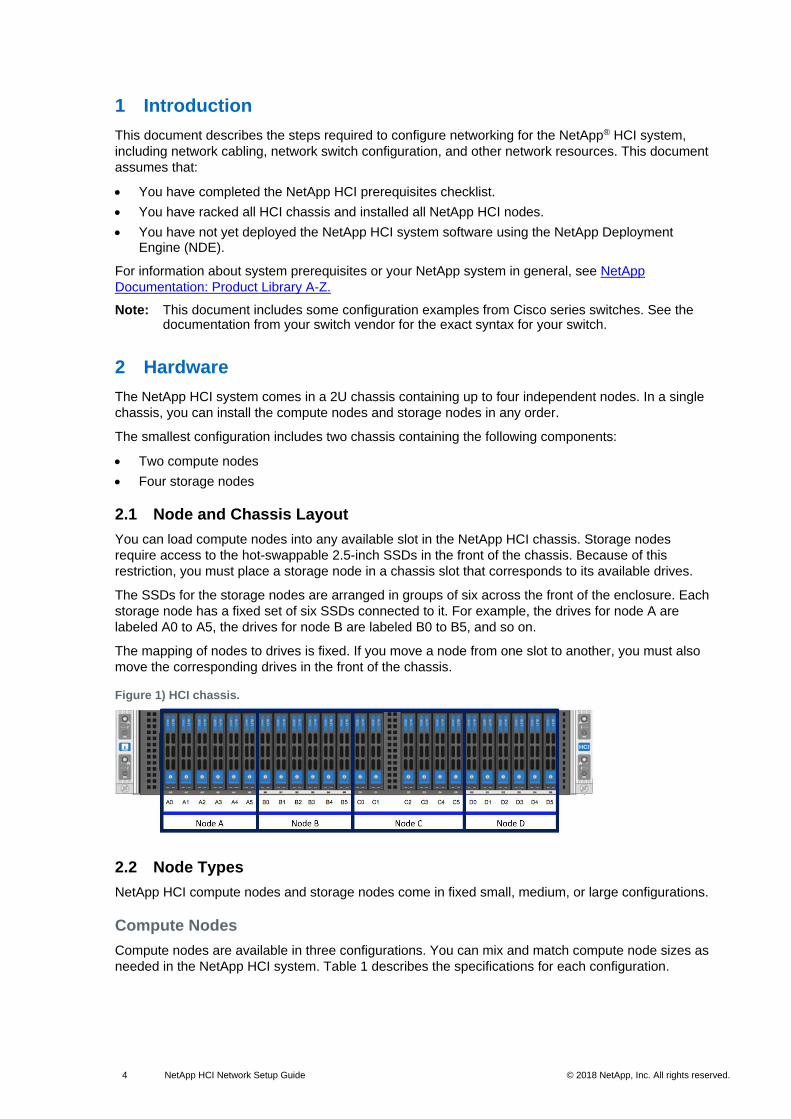
2.1 Node and Chassis Layout
You can load compute nodes into any available slot in the NetApp HCI chassis. Storage nodes
require access to the hot-swappable 2.5-inch SSDs in the front of the chassis. Because of this
restriction, you must place a storage node in a chassis slot that corresponds to its available drives.
The SSDs for the storage nodes are arranged in groups of six across the front of the enclosure. Each
storage node has a fixed set of six SSDs connected to it. For example, the drives for node A are
labeled A0 to A5, the drives for node B are labeled B0 to B5, and so on.
The mapping of nodes to drives is fixed. If you move a node from one slot to another, you must also
move the corresponding drives in the front of the chassis.
Figure 1) HCI chassis.
2.2 Node Types
NetApp HCI compute nodes and storage nodes come in fixed small, medium, or large configurations.
Compute Nodes
Compute nodes are available in three configurations. You can mix and match compute node sizes as
needed in the NetApp HCI system. Table 1 describes the specifications for each configuration.
5 NetApp HCI Network Setup Guide © 2018 NetApp, Inc. All rights reserved. © 2016 NetApp, Inc. All rights reserved.
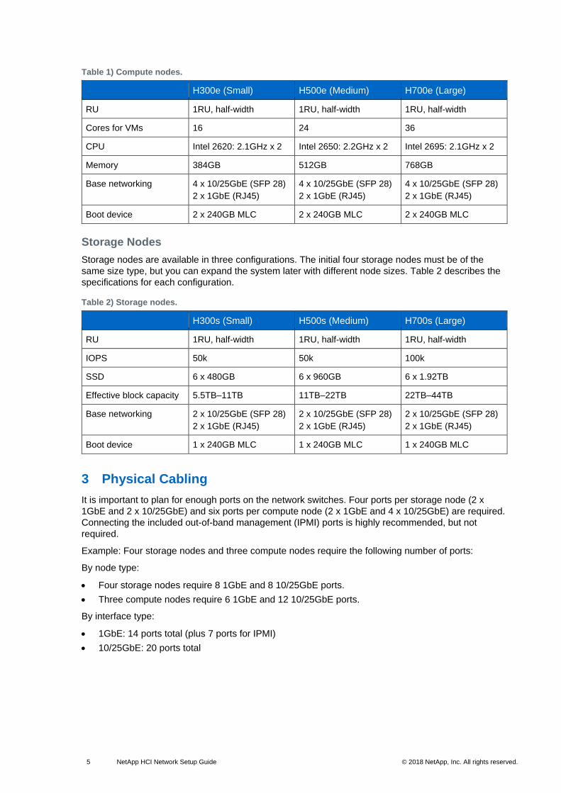
Table 1) Compute nodes.
H300e (Small) H500e (Medium) H700e (Large)
RU 1RU, half-width 1RU, half-width 1RU, half-width
Cores for VMs 16 24 36
CPU Intel 2620: 2.1GHz x 2 Intel 2650: 2.2GHz x 2 Intel 2695: 2.1GHz x 2
Memory 384GB 512GB 768GB
Base networking 4 x 10/25GbE (SFP 28)
2 x 1GbE (RJ45)
4 x 10/25GbE (SFP 28)
2 x 1GbE (RJ45)
4 x 10/25GbE (SFP 28)
2 x 1GbE (RJ45)
Boot device 2 x 240GB MLC 2 x 240GB MLC 2 x 240GB MLC
Storage Nodes
Storage nodes are available in three configurations. The initial four storage nodes must be of the
same size type, but you can expand the system later with different node sizes. Table 2 describes the
specifications for each configuration.
Table 2) Storage nodes.
H300s (Small) H500s (Medium) H700s (Large)
RU 1RU, half-width 1RU, half-width 1RU, half-width
IOPS 50k 50k 100k
SSD 6 x 480GB 6 x 960GB 6 x 1.92TB
Effective block capacity 5.5TB–11TB 11TB–22TB 22TB–44TB
Base networking 2 x 10/25GbE (SFP 28)
2 x 1GbE (RJ45)
2 x 10/25GbE (SFP 28)
2 x 1GbE (RJ45)
2 x 10/25GbE (SFP 28)
2 x 1GbE (RJ45)
Boot device 1 x 240GB MLC 1 x 240GB MLC 1 x 240GB MLC
3 Physical Cabling
It is important to plan for enough ports on the network switches. Four ports per storage node (2 x
1GbE and 2 x 10/25GbE) and six ports per compute node (2 x 1GbE and 4 x 10/25GbE) are required.
Connecting the included out-of-band management (IPMI) ports is highly recommended, but not
required.
Example: Four storage nodes and three compute nodes require the following number of ports:
By node type:
• Four storage nodes require 8 1GbE and 8 10/25GbE ports.
• Three compute nodes require 6 1GbE and 12 10/25GbE ports.
By interface type:
• 1GbE: 14 ports total (plus 7 ports for IPMI)
• 10/25GbE: 20 ports total
6 NetApp HCI Network Setup Guide © 2018 NetApp, Inc. All rights reserved. © 2016 NetApp, Inc. All rights reserved.
3.1 Detailed Physical NIC Layout
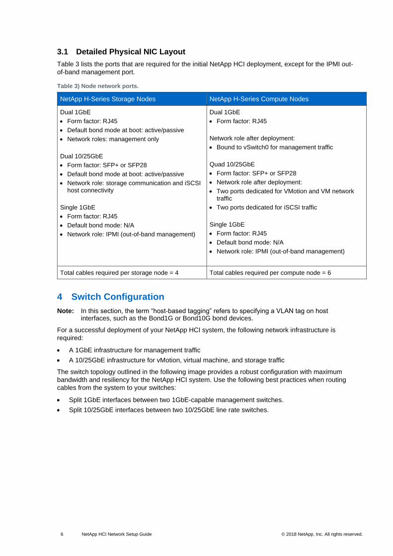
Table 3 lists the ports that are required for the initial NetApp HCI deployment, except for the IPMI out-
of-band management port.
Table 3) Node network ports.
NetApp H-Series Storage Nodes NetApp H-Series Compute Nodes
Dual 1GbE
• Form factor: RJ45
• Default bond mode at boot: active/passive
• Network roles: management only
Dual 10/25GbE
• Form factor: SFP+ or SFP28
• Default bond mode at boot: active/passive
• Network role: storage communication and iSCSI host connectivity
Single 1GbE
• Form factor: RJ45
• Default bond mode: N/A
• Network role: IPMI (out-of-band management)
Dual 1GbE
• Form factor: RJ45
Network role after deployment:
• Bound to vSwitch0 for management traffic
Quad 10/25GbE
• Form factor: SFP+ or SFP28
• Network role after deployment:
• Two ports dedicated for VMotion and VM network traffic
• Two ports dedicated for iSCSI traffic
Single 1GbE
• Form factor: RJ45
• Default bond mode: N/A
• Network role: IPMI (out-of-band management)
Total cables required per storage node = 4 Total cables required per compute node = 6
4 Switch Configuration
Note: In this section, the term “host-based tagging” refers to specifying a VLAN tag on host interfaces, such as the Bond1G or Bond10G bond devices.
For a successful deployment of your NetApp HCI system, the following network infrastructure is
required:
• A 1GbE infrastructure for management traffic
• A 10/25GbE infrastructure for vMotion, virtual machine, and storage traffic
The switch topology outlined in the following image provides a robust configuration with maximum
bandwidth and resiliency for the NetApp HCI system. Use the following best practices when routing
cables from the system to your switches:
• Split 1GbE interfaces between two 1GbE-capable management switches.
• Split 10/25GbE interfaces between two 10/25GbE line rate switches.
7 NetApp HCI Network Setup Guide © 2018 NetApp, Inc. All rights reserved. © 2016 NetApp, Inc. All rights reserved.
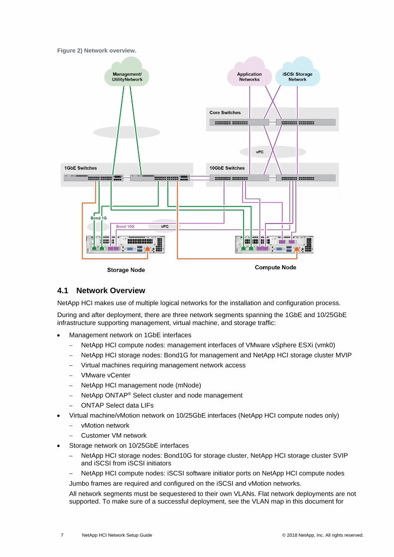
Figure 2) Network overview.
4.1 Network Overview
NetApp HCI makes use of multiple logical networks for the installation and configuration process.
During and after deployment, there are three network segments spanning the 1GbE and 10/25GbE
infrastructure supporting management, virtual machine, and storage traffic:
• Management network on 1GbE interfaces
NetApp HCI compute nodes: management interfaces of VMware vSphere ESXi (vmk0)
NetApp HCI storage nodes: Bond1G for management and NetApp HCI storage cluster MVIP
Virtual machines requiring management network access
VMware vCenter
NetApp HCI management node (mNode)
NetApp ONTAP® Select cluster and node management
ONTAP Select data LIFs
• Virtual machine/vMotion network on 10/25GbE interfaces (NetApp HCI compute nodes only)
vMotion network
Customer VM network
• Storage network on 10/25GbE interfaces
NetApp HCI storage nodes: Bond10G for storage cluster, NetApp HCI storage cluster SVIP and iSCSI from iSCSI initiators
NetApp HCI compute nodes: iSCSI software initiator ports on NetApp HCI compute nodes
Jumbo frames are required and configured on the iSCSI and vMotion networks.
All network segments must be sequestered to their own VLANs. Flat network deployments are not supported. To make sure of a successful deployment, see the VLAN map in this document for
8 NetApp HCI Network Setup Guide © 2018 NetApp, Inc. All rights reserved. © 2016 NetApp, Inc. All rights reserved.
information about how to configure NetApp HCI compute and storage node interfaces on their respective VLANs.
4.2 VPC
You should configure Cisco virtual port channel (vPC) or the equivalent on the switches handling the
storage network for NetApp HCI. vPC eases configuration of LACP and port channels and provides a
loop-free topology between switches and the 10/25GbE ports on the storage nodes.
4.3 Jumbo Frames
The NetApp HCI system requires jumbo frames for all 10/25GbE interfaces on the network. Failure to
enable jumbo frames causes configuration issues for the storage nodes as well as connectivity
problems on the iSCSI and vMotion network.
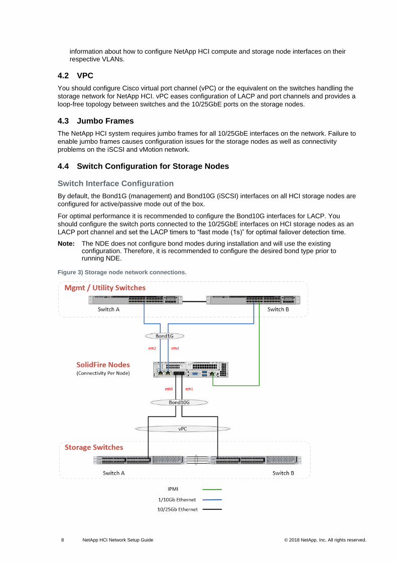
4.4 Switch Configuration for Storage Nodes
Switch Interface Configuration
By default, the Bond1G (management) and Bond10G (iSCSI) interfaces on all HCI storage nodes are
configured for active/passive mode out of the box.
For optimal performance it is recommended to configure the Bond10G interfaces for LACP. You
should configure the switch ports connected to the 10/25GbE interfaces on HCI storage nodes as an
LACP port channel and set the LACP timers to “fast mode (1s)” for optimal failover detection time.
Note: The NDE does not configure bond modes during installation and will use the existing configuration. Therefore, it is recommended to configure the desired bond type prior to running NDE.
Figure 3) Storage node network connections.
9 NetApp HCI Network Setup Guide © 2018 NetApp, Inc. All rights reserved. © 2016 NetApp, Inc. All rights reserved.
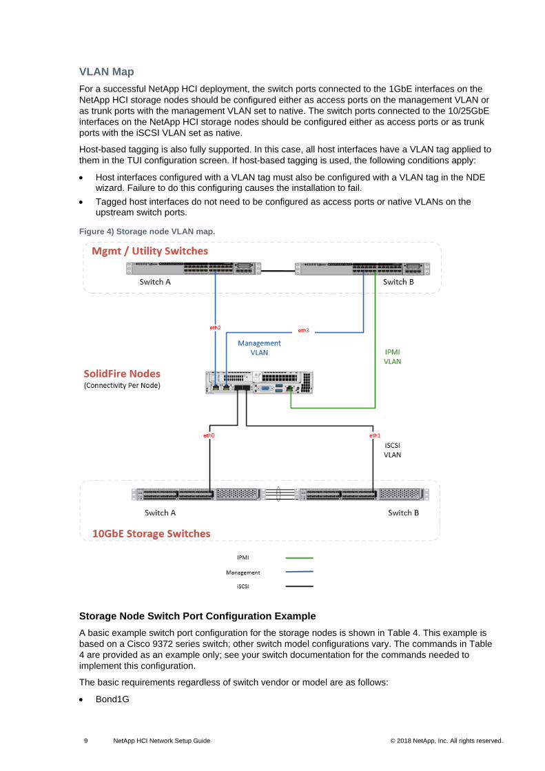
VLAN Map
For a successful NetApp HCI deployment, the switch ports connected to the 1GbE interfaces on the
NetApp HCI storage nodes should be configured either as access ports on the management VLAN or
as trunk ports with the management VLAN set to native. The switch ports connected to the 10/25GbE
interfaces on the NetApp HCI storage nodes should be configured either as access ports or as trunk
ports with the iSCSI VLAN set as native.
Host-based tagging is also fully supported. In this case, all host interfaces have a VLAN tag applied to
them in the TUI configuration screen. If host-based tagging is used, the following conditions apply:
• Host interfaces configured with a VLAN tag must also be configured with a VLAN tag in the NDE wizard. Failure to do this configuring causes the installation to fail.
• Tagged host interfaces do not need to be configured as access ports or native VLANs on the upstream switch ports.
Figure 4) Storage node VLAN map.
Storage Node Switch Port Configuration Example
A basic example switch port configuration for the storage nodes is shown in Table 4. This example is
based on a Cisco 9372 series switch; other switch model configurations vary. The commands in Table
4 are provided as an example only; see your switch documentation for the commands needed to
implement this configuration.
The basic requirements regardless of switch vendor or model are as follows:
• Bond1G
10 NetApp HCI Network Setup Guide © 2018 NetApp, Inc. All rights reserved. © 2016 NetApp, Inc. All rights reserved.
Switch ports should be configured as access VLANs on the management network.
• 10Gb ports
LACP should be configured.
Switch ports should be configured as trunks.
All VLANs required for iSCSI access should be allowed on the trunk.
Jumbo frames must be enabled.
Spanning tree should be disabled for host-facing trunk ports.
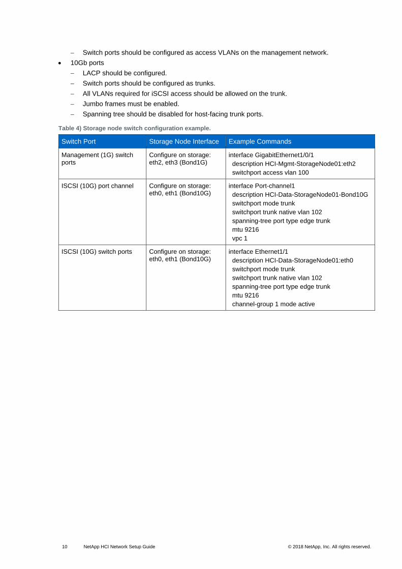
Table 4) Storage node switch configuration example.
Switch Port Storage Node Interface Example Commands
Management (1G) switch ports
Configure on storage: eth2, eth3 (Bond1G)
interface GigabitEthernet1/0/1
description HCI-Mgmt-StorageNode01:eth2
switchport access vlan 100
ISCSI (10G) port channel Configure on storage: eth0, eth1 (Bond10G)
interface Port-channel1
description HCI-Data-StorageNode01-Bond10G
switchport mode trunk
switchport trunk native vlan 102
spanning-tree port type edge trunk
mtu 9216
vpc 1
ISCSI (10G) switch ports Configure on storage: eth0, eth1 (Bond10G)
interface Ethernet1/1
description HCI-Data-StorageNode01:eth0
switchport mode trunk
switchport trunk native vlan 102
spanning-tree port type edge trunk
mtu 9216
channel-group 1 mode active
11 NetApp HCI Network Setup Guide © 2018 NetApp, Inc. All rights reserved. © 2016 NetApp, Inc. All rights reserved.
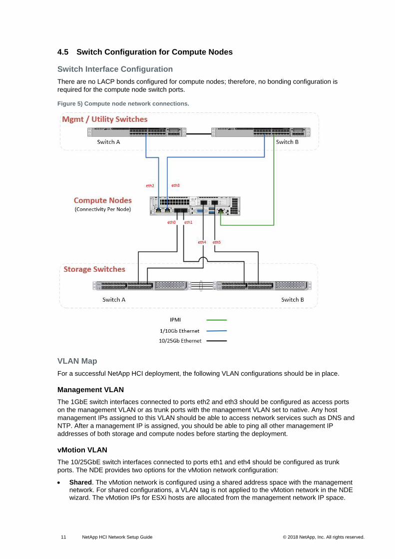
4.5 Switch Configuration for Compute Nodes
Switch Interface Configuration
There are no LACP bonds configured for compute nodes; therefore, no bonding configuration is
required for the compute node switch ports.
Figure 5) Compute node network connections.
VLAN Map
For a successful NetApp HCI deployment, the following VLAN configurations should be in place.
Management VLAN
The 1GbE switch interfaces connected to ports eth2 and eth3 should be configured as access ports
on the management VLAN or as trunk ports with the management VLAN set to native. Any host
management IPs assigned to this VLAN should be able to access network services such as DNS and
NTP. After a management IP is assigned, you should be able to ping all other management IP
addresses of both storage and compute nodes before starting the deployment.
vMotion VLAN
The 10/25GbE switch interfaces connected to ports eth1 and eth4 should be configured as trunk
ports. The NDE provides two options for the vMotion network configuration:
• Shared. The vMotion network is configured using a shared address space with the management network. For shared configurations, a VLAN tag is not applied to the vMotion network in the NDE wizard. The vMotion IPs for ESXi hosts are allocated from the management network IP space.
12 NetApp HCI Network Setup Guide © 2018 NetApp, Inc. All rights reserved. © 2016 NetApp, Inc. All rights reserved.
This allocation requires the VLAN for the management network to be configured as the native VLAN on these trunk ports. This management VLAN on as is configured on the 1GbE ports.
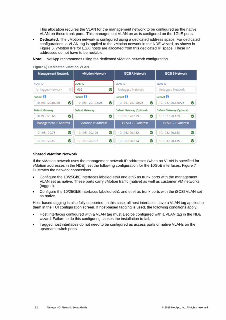
• Dedicated. The vMotion network is configured using a dedicated address space. For dedicated configurations, a VLAN tag is applied to the vMotion network in the NDE wizard, as shown in Figure 6. vMotion IPs for ESXi hosts are allocated from this dedicated IP space. These IP addresses do not have to be routable.
Note: NetApp recommends using the dedicated vMotion network configuration.
Figure 6) Dedicated vMotion VLAN.
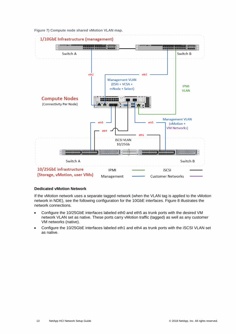
Shared vMotion Network
If the vMotion network uses the management network IP addresses (when no VLAN is specified for
vMotion addresses in the NDE), set the following configuration for the 10GbE interfaces. Figure 7
illustrates the network connections.
• Configure the 10/25GbE interfaces labeled eth0 and eth5 as trunk ports with the management VLAN set as native. These ports carry vMotion traffic (native) as well as customer VM networks (tagged).
• Configure the 10/25GbE interfaces labeled eth1 and eth4 as trunk ports with the iSCSI VLAN set as native.
Host-based tagging is also fully supported. In this case, all host interfaces have a VLAN tag applied to
them in the TUI configuration screen. If host-based tagging is used, the following conditions apply:
• Host interfaces configured with a VLAN tag must also be configured with a VLAN tag in the NDE wizard. Failure to do this configuring causes the installation to fail.
• Tagged host interfaces do not need to be configured as access ports or native VLANs on the upstream switch ports.
13 NetApp HCI Network Setup Guide © 2018 NetApp, Inc. All rights reserved. © 2016 NetApp, Inc. All rights reserved.
Figure 7) Compute node shared vMotion VLAN map.
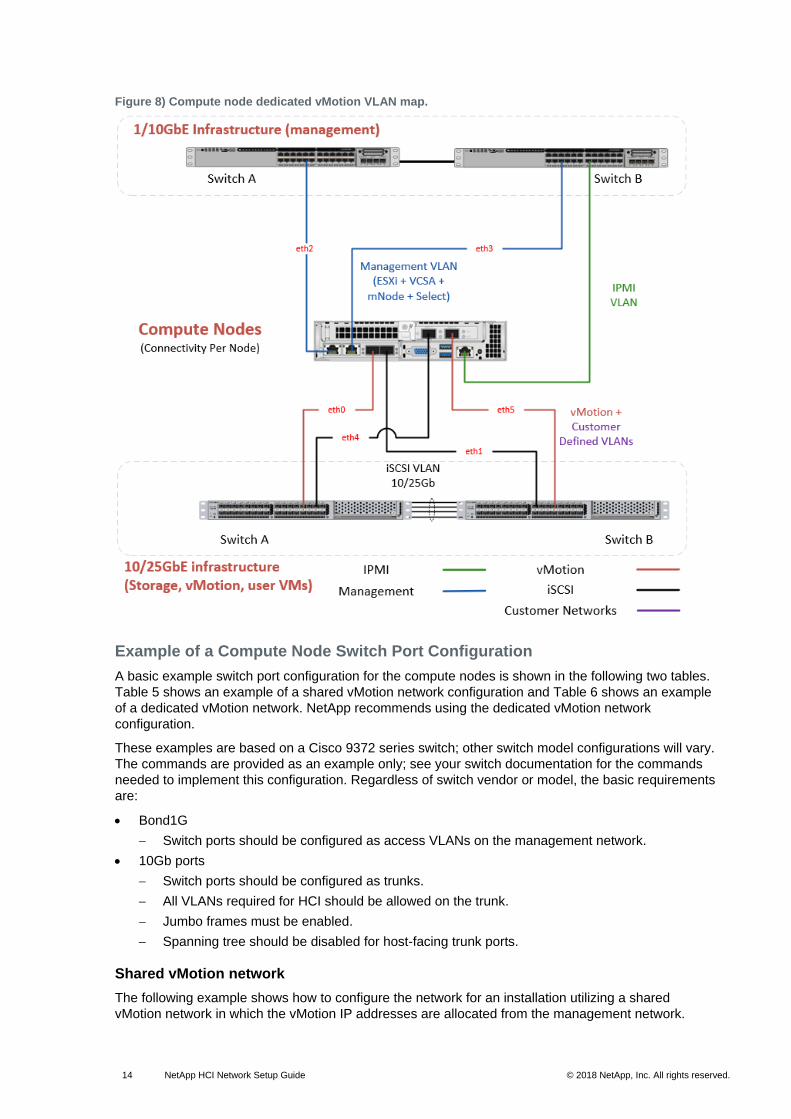
Dedicated vMotion Network
If the vMotion network uses a separate tagged network (when the VLAN tag is applied to the vMotion
network in NDE), see the following configuration for the 10GbE interfaces. Figure 8 illustrates the
network connections.
• Configure the 10/25GbE interfaces labeled eth0 and eth5 as trunk ports with the desired VM network VLAN set as native. These ports carry vMotion traffic (tagged) as well as any customer VM networks (native).
• Configure the 10/25GbE interfaces labeled eth1 and eth4 as trunk ports with the iSCSI VLAN set as native.
14 NetApp HCI Network Setup Guide © 2018 NetApp, Inc. All rights reserved. © 2016 NetApp, Inc. All rights reserved.
Figure 8) Compute node dedicated vMotion VLAN map.
Example of a Compute Node Switch Port Configuration
A basic example switch port configuration for the compute nodes is shown in the following two tables.
Table 5 shows an example of a shared vMotion network configuration and Table 6 shows an example
of a dedicated vMotion network. NetApp recommends using the dedicated vMotion network
configuration.
These examples are based on a Cisco 9372 series switch; other switch model configurations will vary.
The commands are provided as an example only; see your switch documentation for the commands
needed to implement this configuration. Regardless of switch vendor or model, the basic requirements
are:
• Bond1G
Switch ports should be configured as access VLANs on the management network.
• 10Gb ports
Switch ports should be configured as trunks.
All VLANs required for HCI should be allowed on the trunk.
Jumbo frames must be enabled.
Spanning tree should be disabled for host-facing trunk ports.
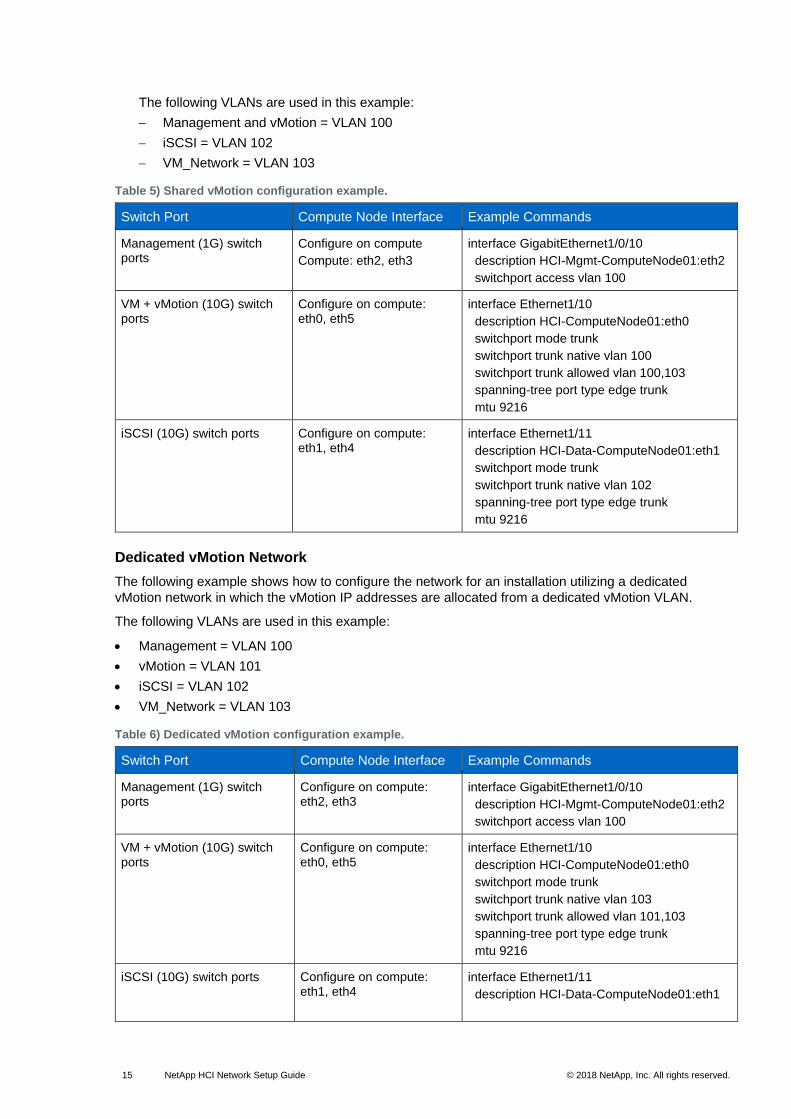
Shared vMotion network
The following example shows how to configure the network for an installation utilizing a shared
vMotion network in which the vMotion IP addresses are allocated from the management network.
15 NetApp HCI Network Setup Guide © 2018 NetApp, Inc. All rights reserved. © 2016 NetApp, Inc. All rights reserved.
The following VLANs are used in this example:
Management and vMotion = VLAN 100
iSCSI = VLAN 102
VM_Network = VLAN 103
Table 5) Shared vMotion configuration example.
Switch Port Compute Node Interface Example Commands
Management (1G) switch ports
Configure on compute
Compute: eth2, eth3
interface GigabitEthernet1/0/10
description HCI-Mgmt-ComputeNode01:eth2
switchport access vlan 100
VM + vMotion (10G) switch ports
Configure on compute: eth0, eth5
interface Ethernet1/10
description HCI-ComputeNode01:eth0
switchport mode trunk
switchport trunk native vlan 100
switchport trunk allowed vlan 100,103
spanning-tree port type edge trunk
mtu 9216
iSCSI (10G) switch ports Configure on compute: eth1, eth4
interface Ethernet1/11
description HCI-Data-ComputeNode01:eth1
switchport mode trunk
switchport trunk native vlan 102
spanning-tree port type edge trunk
mtu 9216
Dedicated vMotion Network
The following example shows how to configure the network for an installation utilizing a dedicated
vMotion network in which the vMotion IP addresses are allocated from a dedicated vMotion VLAN.
The following VLANs are used in this example:
• Management = VLAN 100
• vMotion = VLAN 101
• iSCSI = VLAN 102
• VM_Network = VLAN 103
Table 6) Dedicated vMotion configuration example.
Switch Port Compute Node Interface Example Commands
Management (1G) switch ports
Configure on compute: eth2, eth3
interface GigabitEthernet1/0/10
description HCI-Mgmt-ComputeNode01:eth2
switchport access vlan 100
VM + vMotion (10G) switch ports
Configure on compute: eth0, eth5
interface Ethernet1/10
description HCI-ComputeNode01:eth0
switchport mode trunk
switchport trunk native vlan 103
switchport trunk allowed vlan 101,103
spanning-tree port type edge trunk
mtu 9216
iSCSI (10G) switch ports Configure on compute: eth1, eth4
interface Ethernet1/11
description HCI-Data-ComputeNode01:eth1
16 NetApp HCI Network Setup Guide © 2018 NetApp, Inc. All rights reserved. © 2016 NetApp, Inc. All rights reserved.
Switch Port Compute Node Interface Example Commands
switchport mode trunk
switchport trunk native vlan 102
spanning-tree port type edge trunk
mtu 9216
5 Deploying NetApp HCI Using NetApp Deployment Engine
After you power on all NetApp HCI compute servers and storage nodes, 1GbE and 10GbE interfaces
must be assigned IPv4 addresses if they are not automatically acquired via DHCP. NetApp HCI
servers and nodes must be available on the network so that they can be discovered during the
deployment process using the NetApp Deployment Engine.
If your environment does not use DHCP on the management and storage networks, NetApp HCI
compute nodes and storage nodes require the following number of IP addresses per node:
• One IPv4 address on each Bond1G interface
• One IPv4 address on each Bond10G interface
The steps required to manually assign IP addresses to each interface are outlined in the NetApp H-
Series Installation and Setup Instructions (NetApp H-Series ISI). The document is provided in the
product box and is also available from NetApp Documentation: Product Library A-Z.
The next step is the deployment of the NetApp HCI system using the NetApp Deployment Engine.
See the NetApp HCI Deployment Engine User Guide, also available from NetApp Documentation:
Product Library A-Z.
6 Network After NetApp HCI Deployment
This section details how the physical connections into the switching fabric are consumed by the
NetApp HCI storage nodes and compute nodes.
6.1 Storage Node Physical-to-Logical Port Map
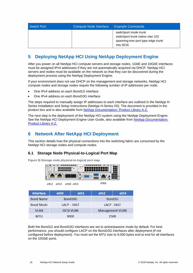
Figure 9) Storage node physical-to-logical port map.
Both the Bond1G and Bond10G interfaces are set to active/passive mode by default. For best
performance, you should configure LACP on the Bond10G interfaces after deployment (if not
configured before deployment). You must set the MTU size to 9,000 bytes end to end for all interfaces
on the 10GbE ports.
17 NetApp HCI Network Setup Guide © 2018 NetApp, Inc. All rights reserved. © 2016 NetApp, Inc. All rights reserved.
6.2 vCenter Network Switch Options
NDE 1.2 provides the option of installing either a vSphere distributed switch (VDS) or a set of vSphere
standard switches (VSSs) for host networking.
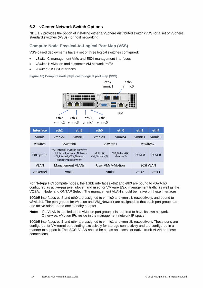
Compute Node Physical-to-Logical Port Map (VSS)
VSS-based deployments have a set of three logical switches configured:
• vSwitch0: management VMs and ESXi management interfaces
• vSwitch1: vMotion and customer VM network traffic
• vSwitch2: iSCSI interfaces
Figure 10) Compute node physical to-logical port map (VSS).
For NetApp HCI compute nodes, the 1GbE interfaces eth2 and eth3 are bound to vSwitch0,
configured as active-passive failover, and used for VMware ESXi management traffic as well as the
VCSA, mNode, and ONTAP Select. The management VLAN should be native on these interfaces.
10GbE interfaces eth5 and eth0 are assigned to vmnic0 and vmnic4, respectively, and bound to
vSwitch1. The port groups for vMotion and VM_Network are assigned so that each port group has
one active adapter and one standby adapter.
Note: If a VLAN is applied to the vMotion port group, it is required to have its own network. Otherwise, vMotion IPs reside in the management network IP space.
10GbE interfaces eth1 and eth4 are assigned to vmnic1 and vmnic5, respectively. These ports are
configured for VMkernel port binding exclusively for storage connectivity and are configured in a
manner to support it. The iSCSI VLAN should be set as an access or native trunk VLAN on these
connections.
18 NetApp HCI Network Setup Guide © 2018 NetApp, Inc. All rights reserved. © 2016 NetApp, Inc. All rights reserved.
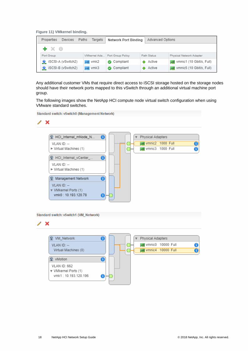
Figure 11) VMkernel binding.
Any additional customer VMs that require direct access to iSCSI storage hosted on the storage nodes
should have their network ports mapped to this vSwitch through an additional virtual machine port
group.
The following images show the NetApp HCI compute node virtual switch configuration when using
VMware standard switches.
19 NetApp HCI Network Setup Guide © 2018 NetApp, Inc. All rights reserved. © 2016 NetApp, Inc. All rights reserved.
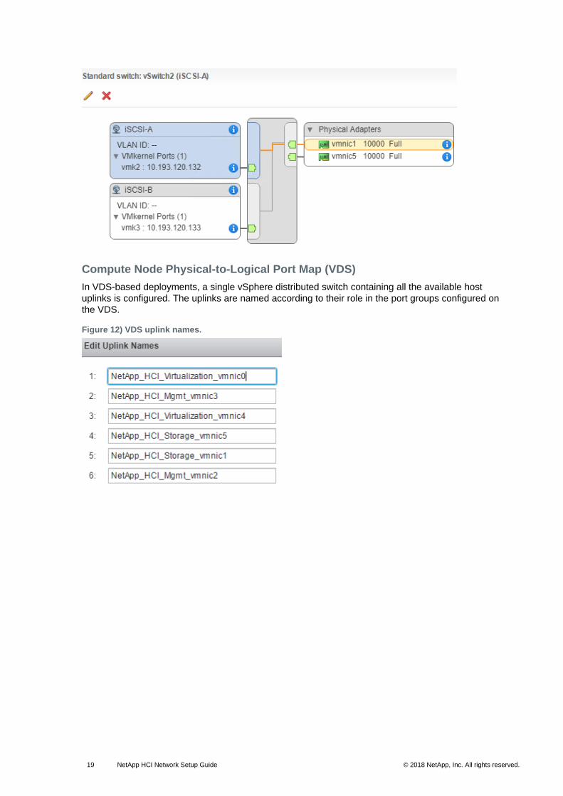
Compute Node Physical-to-Logical Port Map (VDS)
In VDS-based deployments, a single vSphere distributed switch containing all the available host
uplinks is configured. The uplinks are named according to their role in the port groups configured on
the VDS.
Figure 12) VDS uplink names.
20 NetApp HCI Network Setup Guide © 2018 NetApp, Inc. All rights reserved. © 2016 NetApp, Inc. All rights reserved.
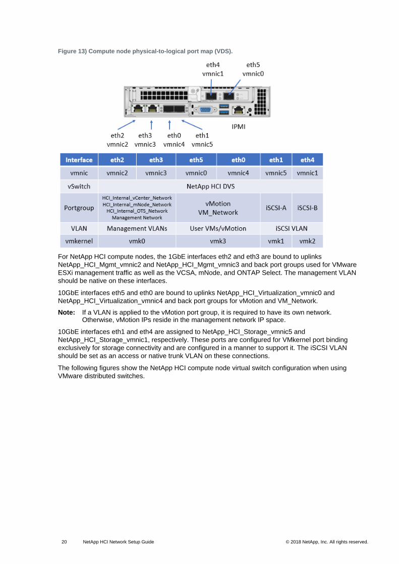
Figure 13) Compute node physical-to-logical port map (VDS).
For NetApp HCI compute nodes, the 1GbE interfaces eth2 and eth3 are bound to uplinks
NetApp_HCI_Mgmt_vmnic2 and NetApp_HCI_Mgmt_vmnic3 and back port groups used for VMware
ESXi management traffic as well as the VCSA, mNode, and ONTAP Select. The management VLAN
should be native on these interfaces.
10GbE interfaces eth5 and eth0 are bound to uplinks NetApp_HCI_Virtualization_vmnic0 and
NetApp_HCI_Virtualization_vmnic4 and back port groups for vMotion and VM_Network.
Note: If a VLAN is applied to the vMotion port group, it is required to have its own network. Otherwise, vMotion IPs reside in the management network IP space.
10GbE interfaces eth1 and eth4 are assigned to NetApp_HCI_Storage_vmnic5 and
NetApp_HCI_Storage_vmnic1, respectively. These ports are configured for VMkernel port binding
exclusively for storage connectivity and are configured in a manner to support it. The iSCSI VLAN
should be set as an access or native trunk VLAN on these connections.
The following figures show the NetApp HCI compute node virtual switch configuration when using
VMware distributed switches.
21 NetApp HCI Network Setup Guide © 2018 NetApp, Inc. All rights reserved. © 2016 NetApp, Inc. All rights reserved.
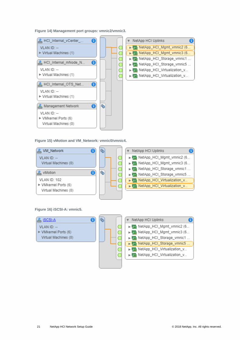
Figure 14) Management port groups: vmnic2/vmnic3.
Figure 15) vMotion and VM_Network: vmnic0/vmnic4.
Figure 16) iSCSI-A: vmnic5.
22 NetApp HCI Network Setup Guide © 2018 NetApp, Inc. All rights reserved. © 2016 NetApp, Inc. All rights reserved.
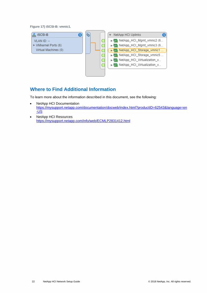
Figure 17) iSCSI-B: vmnic1.
Where to Find Additional Information
To learn more about the information described in this document, see the following:
• NetApp HCI Documentation https://mysupport.netapp.com/documentation/docweb/index.html?productID=62543&language=en-US
• NetApp HCI Resources https://mysupport.netapp.com/info/web/ECMLP2831412.html

23 NetApp HCI Network Setup Guide © 2018 NetApp, Inc. All rights reserved. © 2016 NetApp, Inc. All rights reserved.
Refer to the Interoperability Matrix Tool (IMT) on the NetApp Support site to validate that the exact product and feature versions described in this document are supported for your specific environment. The NetApp IMT defines the product components and versions that can be used to construct configurations that are supported by NetApp. Specific results depend on each customer’s installation in accordance with published specifications.
Copyright Information
Copyright © 2018 NetApp, Inc. All rights reserved. Printed in the U.S. No part of this document covered by copyright may be reproduced in any form or by any means—graphic, electronic, or mechanical, including photocopying, recording, taping, or storage in an electronic retrieval system—without prior written permission of the copyright owner.
Software derived from copyrighted NetApp material is subject to the following license and disclaimer:
THIS SOFTWARE IS PROVIDED BY NETAPP “AS IS” AND WITHOUT ANY EXPRESS OR IMPLIED WARRANTIES, INCLUDING, BUT NOT LIMITED TO, THE IMPLIED WARRANTIES OF MERCHANTABILITY AND FITNESS FOR A PARTICULAR PURPOSE, WHICH ARE HEREBY DISCLAIMED. IN NO EVENT SHALL NETAPP BE LIABLE FOR ANY DIRECT, INDIRECT, INCIDENTAL, SPECIAL, EXEMPLARY, OR CONSEQUENTIAL DAMAGES (INCLUDING, BUT NOT LIMITED TO, PROCUREMENT OF SUBSTITUTE GOODS OR SERVICES; LOSS OF USE, DATA, OR PROFITS; OR BUSINESS INTERRUPTION) HOWEVER CAUSED AND ON ANY THEORY OF LIABILITY, WHETHER IN CONTRACT, STRICT LIABILITY, OR TORT (INCLUDING NEGLIGENCE OR OTHERWISE) ARISING IN ANY WAY OUT OF THE USE OF THIS SOFTWARE, EVEN IF ADVISED OF THE POSSIBILITY OF SUCH DAMAGE.
NetApp reserves the right to change any products described herein at any time, and without notice. NetApp assumes no responsibility or liability arising from the use of products described herein, except as expressly agreed to in writing by NetApp. The use or purchase of this product does not convey a license under any patent rights, trademark rights, or any other intellectual property rights of NetApp.
The product described in this manual may be protected by one or more U.S. patents, foreign patents, or pending applications.
RESTRICTED RIGHTS LEGEND: Use, duplication, or disclosure by the government is subject to restrictions as set forth in subparagraph (c)(1)(ii) of the Rights in Technical Data and Computer Software clause at DFARS 252.277-7103 (October 1988) and FAR 52-227-19 (June 1987).
Trademark Information
NETAPP, the NETAPP logo, and the marks listed at http://www.netapp.com/TM are trademarks of NetApp, Inc. Other company and product names may be trademarks of their respective owners.
TR-4679-0418