Embed Size (px)
Citation preview

Net Metering
Interconnection Requirements
50 kW and Below
Revision 0
May 31, 2013
Table of Contents
1 Introduction .......................................................................................................................................... 3
1.1 Disclaimers .................................................................................................................................... 4
2 BC Hydro Distribution System ............................................................................................................... 5
3 Interconnecting Simple Net Metering Generators ............................................................................... 6
3.1 What Qualifies as a Simple Net Metering Generator? ................................................................. 6
3.2 Requirements ................................................................................................................................ 6
3.2.1 Equipment ..................................................................................................................... 6
3.2.2 Protection ...................................................................................................................... 7
3.2.3 Power Quality ................................................................................................................ 7
3.2.4 Commissioning & Operation ......................................................................................... 7
4 Interconnecting Complex Net Metering Generators ............................................................................ 8
4.1 What Qualifies as a Complex Net Metering Generator? .............................................................. 8
4.2 Requirements ................................................................................................................................ 8
4.2.1 Equipment ..................................................................................................................... 8
4.2.1.1 Common Requirements ................................................................................................ 8
4.2.1.2 Special Requirements: Induction Generators ............................................................... 9
4.2.1.3 Special Requirements: Customer Owned Transformers ............................................. 10
4.2.2 Protection – Inverter-Based Systems .......................................................................... 10
4.2.3 Protection – Induction and Synchronous Generators ................................................ 11
4.2.4 Power Quality .............................................................................................................. 12
4.2.5 Commissioning & Operation ....................................................................................... 12
Appendix A: Definitions and References ............................................................................................... 14
Appendix B: Figures and Single Line Diagrams ...................................................................................... 19
Appendix C: Technical Tables ................................................................................................................ 23
Appendix D: Testing and Commissioning Tables ................................................................................... 28
Appendix E: Application Data Requirements ........................................................................................ 31
Appendix F: Declaration of Compatibility (DoC) ................................................................................... 34

NMIR R1 - May 31, 2013 3
1 Introduction
With the Net Metering program, BC Hydro provides a way for residential and commercial customers to connect a small energy source to the BC Hydro Distribution System to offset their loads. This document contains the technical requirements for connecting generation for the purposes of Net Metering under Rate Schedule 1289 of the BC Hydro Electric Tariff. The eligibility requirements are given there, but the generation must have an aggregate nameplate rating of 50 kW or less.
In this document, customers who are connecting a generator are referred to as Distributed Generators (DGs). DGs with generation other than Net Metering should refer to BC Hydro Interconnection Requirements for Power Generators 35kV and Below and consult with BC Hydro.
The requirements outlined in this document are intended to:
ensure the safety of the customer, BC Hydro personnel, and the public;
maintain reliability and power quality on the Distribution System; and
establish the range of operating conditions that DGs will encounter.
Under Net Metering, the aggregate nameplate rating of the generators at the Point of Common Coupling (or point of delivery) shall not exceed the capacity of the customer’s existing electrical service. The customer may upgrade their electrical service to meet this requirement, at their cost.
Net Metering (NM) Generators are classified into two categories: Simple NM Generators and Complex NM Generators. The technical and application requirements are simplified for Simple NM Generators, while Complex NM Generators are subject to a full review.
How to use this document
1. Confirm the generator can operate within the Distribution System parameters in Section 2; 2. Determine whether the generator is Simple NM or Complex NM, based on the criteria in Section 3.1
and Section 4.1; 3. Refer to the applicable interconnection requirements for Simple NM Generators (Section 3.2) or
Complex NM Generators (Section 4.2); and 4. Further information on all standards and references referred to in this document can be found in
Appendix A.2. The titles of all standards and references found in Appendix A.2 are italicised.

NMIR R1 - May 31, 2013 4
1.1 Disclaimers
The information contained in this document is subject to future revisions. Important notes of limitations include:
this document is not a replacement for electrical codes or other applicable standards
this document is not intended or provided by BC Hydro as a design specification or as an instruction manual for the DG owner, employees or agents, and the document shall not be used by the proponent, his employees or agents for those purposes. Persons using this information do so at no risk to BC Hydro and they rely solely upon themselves to ensure that their use of all or part of this document is appropriate in the particular circumstance,
the DG owner, employees or agents recognize that they are, at all times, solely responsible for the generator plant design, construction and operation. BC Hydro, its employees or agents shall not be or become the agent of the proponent in any manner howsoever arising,
the advice by BC Hydro, its employees or agents, that the generating plant design or equipment meets certain BC Hydro requirements does not mean, expressly or by implication, that all or any of the requirements of the law or good Engineering practice have been met by the owner and such judgement shall not be construed by the owner or others as an endorsement of the design or as a warranty by BC Hydro, its employees and agents, of the design or equipment, or any part thereof.
1.2 Revision History
Date Revision Comments
October 22, 2003 Initial release.
May 3, 2011 Release of Interconnection Requirements for Small NM DGs (Solar PV, ≤ 25 kW) (NMIR/25) as Addendum to NMIR/50. Standalone document.
May 31, 2013 1 Major revision. Combined old NMIR/50 kW and NMIR <25 kW and updated to new CSA Standards.
NMIR R1 - May 31, 2013 5
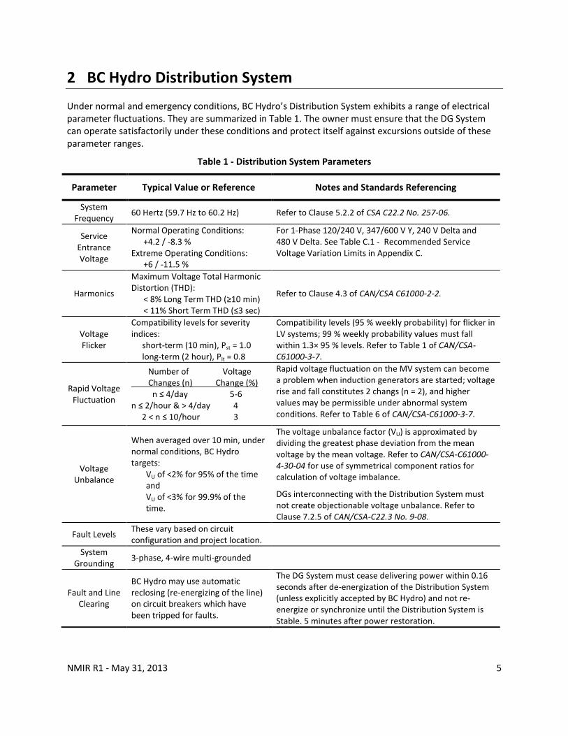
2 BC Hydro Distribution System
Under normal and emergency conditions, BC Hydro’s Distribution System exhibits a range of electrical parameter fluctuations. They are summarized in Table 1. The owner must ensure that the DG System can operate satisfactorily under these conditions and protect itself against excursions outside of these parameter ranges.
Table 1 - Distribution System Parameters
Parameter Typical Value or Reference Notes and Standards Referencing
System Frequency
60 Hertz (59.7 Hz to 60.2 Hz) Refer to Clause 5.2.2 of CSA C22.2 No. 257-06.
Service Entrance Voltage
Normal Operating Conditions: +4.2 / -8.3 %
Extreme Operating Conditions: +6 / -11.5 %
For 1-Phase 120/240 V, 347/600 V Y, 240 V Delta and 480 V Delta. See Table C.1 - Recommended Service Voltage Variation Limits in Appendix C.
Harmonics
Maximum Voltage Total Harmonic Distortion (THD):
< 8% Long Term THD (≥10 min) < 11% Short Term THD (≤3 sec)
Refer to Clause 4.3 of CAN/CSA C61000-2-2.
Voltage Flicker
Compatibility levels for severity indices:
short-term (10 min), Pst = 1.0 long-term (2 hour), Plt = 0.8
Compatibility levels (95 % weekly probability) for flicker in LV systems; 99 % weekly probability values must fall within 1.3× 95 % levels. Refer to Table 1 of CAN/CSA-C61000-3-7.
Rapid Voltage Fluctuation
Number of Voltage Changes (n) Change (%) n ≤ 4/day 5-6 n ≤ 2/hour & > 4/day 4 2 < n ≤ 10/hour 3
Rapid voltage fluctuation on the MV system can become a problem when induction generators are started; voltage rise and fall constitutes 2 changs (n = 2), and higher values may be permissible under abnormal system conditions. Refer to Table 6 of CAN/CSA-C61000-3-7.
Voltage Unbalance
When averaged over 10 min, under normal conditions, BC Hydro targets:
VU of <2% for 95% of the time and VU of <3% for 99.9% of the time.
The voltage unbalance factor (VU) is approximated by dividing the greatest phase deviation from the mean voltage by the mean voltage. Refer to CAN/CSA-C61000-4-30-04 for use of symmetrical component ratios for calculation of voltage imbalance.
DGs interconnecting with the Distribution System must not create objectionable voltage unbalance. Refer to Clause 7.2.5 of CAN/CSA-C22.3 No. 9-08.
Fault Levels These vary based on circuit configuration and project location.
System Grounding
3-phase, 4-wire multi-grounded
Fault and Line Clearing
BC Hydro may use automatic reclosing (re-energizing of the line) on circuit breakers which have been tripped for faults.
The DG System must cease delivering power within 0.16 seconds after de-energization of the Distribution System (unless explicitly accepted by BC Hydro) and not re-energize or synchronize until the Distribution System is Stable. 5 minutes after power restoration.

NMIR R1 - May 31, 2013 6
3 Interconnecting Simple Net Metering Generators
3.1 What Qualifies as a Simple Net Metering Generator?
For the purposes of this document, a Simple Net Metering (NM) Distributed Generator (DG) system shall meet all of the following:
be an inverter-based system installed in accordance with CEC Part I and certified to the requirements of CSA C22.2 No. 107.1-01 for utility interconnection; and
has an aggregate nameplate rating of 27 kW or less (30 kVA at 0.9 power factor) at the Point of Common Coupling (or point of delivery); and
has self-contained revenue metering (services 200 A or less with no CTs and VTs).
3.2 Requirements
This section provides the technical requirements to be met by any Simple NM System that will be interconnected with the Distribution System.
3.2.1 Equipment
General
As applicable, Simple NM DG Systems shall meet:
CEC Part I (see Sections 50, 64 & 84)
CAN/CSA-C22.2 No. 257-06
CAN/CSA-C22.3 No. 9-08
CSA Standard C22.2 No. 107.1-01
Point of Common Coupling
The Point of Common Coupling (PCC) is the point where the Distribution System and the DG owner’s installation interconnect. This is typically at the weatherhead (for overhead service connections) or at the revenue meter base (for underground service connections). BC Hydro is responsible for design, construction, maintenance, and operation of all facilities on the BC Hydro side of the PCC. The DG owner shall be responsible for design, construction, inspection, maintenance, and operation of all facilities on their side of the PCC.
DG System Disconnect Means
All generators interconnected with the Distribution System require a means to safely disconnect them and ensure isolation in accordance with CEC Part I, Section 84. BC Hydro does not require access to the customer’s means of disconnection.

NMIR R1 - May 31, 2013 7
3.2.2 Protection
The generator protection shall be in accordance with CEC Part I and Table C.2 in Appendix C.
Anti-islanding
The anti-islanding requirements of CAN/CSA-C22.2 No. 257-06 and CSA C22.2 No. 107.1-01 require the inverter to cease energizing the Distribution System within 0.1 seconds upon loss of the BC Hydro supply, as specified in Table C.3. This provides for the safety of electrical workers and the public.
Grid-dependent inverters are designed to only energize when the utility (BC Hydro) supply is present, but grid-interactive inverters can also operate in stand-alone (sometimes called off-grid) mode and must be verified to be in grid-dependent mode. A grid-interactive inverter may contain the internal disconnects and transfer switch to ensure isolation from the BC Hydro Distribution System while still supplying an essential load panel. Please see AppendixA.1for more detailed definitions.
3.2.3 Power Quality
Simple NM generators certified to the requirements of CSA C22.2 No. 107.1-01 for utility interconnection meet the power quality requirements for connection to the Distribution System.
3.2.4 Commissioning & Operation
General
The DG owner is required to confirm that all requirements of the manufacturer and Local Regulatory Authority are met, and that the DG System installation meets the requirements of this document and CSA C22.2 No. 257-06. If requested, the DG owner will provide to BC Hydro a list of step-by-step energizing and commissioning procedures prior to DG system commissioning.
The DG owner shall retain a complete set of manuals, installation drawings, permits, inspection and verification test reports and make them available to BC Hydro if requested.
Testing & Commissioning
Prior to completion of DG System commissioning, or whenever the generator system is modified, a verification test shall be performed as recommended by the equipment manufacturer and required by CAN/CSA-C22.2 No. 257-06 Section 7. Testing of the DG System shall include procedures to functionally test all protective elements including verification of inverter trip timing.
Maintenance & Operation
In addition to keeping all equipment well maintained and functional, the DG owner shall verify the generator’s interconnection protective functions according to the manufacturer’s recommended schedule, or at least once a year as required by CAN/CSA-C22.2 No. 257-06 Section 8. If there is no manufacturer’s recommendation, operation of the disconnecting means and verifying that the inverter system automatically ceases to energize is an acceptable method of verification. Maintenance records shall be maintained. Failure to perform and record maintenance can result in disconnection of the DG facility.
The DG owner must notify BC Hydro of any subsequent changes to equipment, by submitting a revised Net Metering Interconnection Application form, to confirm that the proposed equipment modification still meets the requirements to qualify as a Simple NM generator.

NMIR R1 - May 31, 2013 8
4 Interconnecting Complex Net Metering Generators
4.1 What Qualifies as a Complex Net Metering Generator?
The increased complexity and potential for impact on the Distribution System requires that Complex Net Metering (NM) generators be subject to a more rigorous review than Simple NM generators.
For the purposes of this document, a net metering generator system will be deemed a Complex NM generator if it meets any of the following conditions:
is an inverter-based DG Systems that are not certified to the requirements of CSA C22.2 No. 107.1-01 for utility interconnection; or
has an aggregate nameplate rating greater than 27 kW and less than or equal to 50 kW at the Point of Common Coupling (or point of delivery); or
is an induction or synchronous generator; or
has instrument transformer revenue metering (services greater than 200 A).
Typically, the main distinction between Simple DG Systems and Complex DG Systems is that for Complex DG Systems the protection and isolation functions are not connected into factory assembled, tested, and certified single enclosure units with non-adjustable settings.
4.2 Requirements
This section provides the technical requirements to be met by any Complex NM DG System interconnecting with the Distribution System.
4.2.1 Equipment
4.2.1.1 Common Requirements
General
As applicable, Complex NM DG Systems shall meet:
CEC Part I (see Sections 50, 64 & 84)
CAN/CSA-C22.2 No. 257-06
CAN/CSA-C22.3 No. 9-08
CSAC22.2 No. 107.1-01
Point of Common Coupling – Responsibilities and Quantity Measurement
The Point of Common Coupling (PCC) is the point where the Distribution System and the DG owner’s installation interconnect. This is typically at the weatherhead (for overhead service connections) or at the revenue meter base (for underground service connections). BC Hydro is responsible for design, construction, maintenance, and operation of all facilities on the BC Hydro side of the PCC. The DG owner shall be responsible for design, construction, inspection, maintenance, and operation of all facilities on their side of the PCC.

NMIR R1 - May 31, 2013 9
The typical measurement locations of voltage and frequency for protection functions are shown in Table C.8.
Point of Disconnection - Safety
All generators interconnected with the Distribution System require a means to disconnect them and ensure isolation in accordance with CEC Part I, Section 84. Typically, BC Hydro does not require access to the customer’s means of disconnection, except as noted below for instrument transformer metering.
According to Section 5 of BC Hydro Requirements for Secondary Voltage Revenue Metering (750 V and less), DG Systems containing instrument transformer metering shall provide a main service box with the customer main disconnect on the supply side of the instrument transformer compartment, and a lockable disconnect on the load side of the instrument transformer enclosure.
DG Systems that have potential for hazardous infeed (i.e. continue to deliver power to the Distribution System after the system has been de-energized for greater than two seconds) require a facility specific Distribution Operating Order (DOO) to be prepared by the BC Hydro Control Centre to describe procedures for interconnected operation.
Voltage Regulation
The DG System shall not attempt to regulate the voltage and shall not adversely affect voltage at the PCC. BC Hydro will determine if voltage regulation is expected to be a concern and identify solutions during the technical review.
Power Factor
The Complex NM generator is not required to adjust its power factor (PF) but shall be capable of operating in the range of ±0.90 PF. If the Complex NM generator causes the Distribution System to operate outside normal voltage levels at the PCC (see Table C.1 - for the Distribution System voltage variation limits), then the owner may be required to operate the DG System within a narrower PF range or take other compensatory measures.
Interconnection Grounding
In accordance with CSA C22.3 No. 9-08, DG Systems must be grounded as per manufacturer’s recommendations and CEC Part I. The transformer grounding must be coordinated with BC Hydro to ensure it does not cause voltage disturbances and coordination of ground fault protection is maintained.
Interrupting Device Ratings
The design of the DG System must consider the fault current contributions from both BC Hydro and the DG System, to ensure that all circuit fault interrupters are adequately sized. If requested, BC Hydro will inform the DG owner of the present and anticipated future fault current contribution from the Distribution System at the PCC.
4.2.1.2 Special Requirements: Induction Generators
BC Hydro may require induction generators to provide reactive compensation (PF correction capacitors) to ensure the generator operates within a PF range of ±0.9. Conditions on the Distribution System, as well as the addition of reactive compensation, may increase the potential for self-excitation. If self-excitation is determined to be a credible possibility, mitigation measures will be required by BC Hydro.
NMIR R1 - May 31, 2013 10
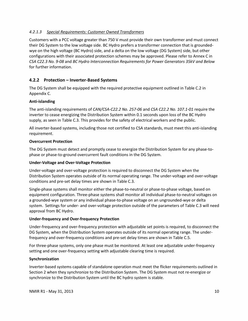
4.2.1.3 Special Requirements: Customer Owned Transformers
Customers with a PCC voltage greater than 750 V must provide their own transformer and must connect their DG System to the low voltage side. BC Hydro prefers a transformer connection that is grounded-wye on the high voltage (BC Hydro) side, and a delta on the low voltage (DG System) side, but other configurations with their associated protection schemes may be approved. Please refer to Annex C in CSA C22.3 No. 9-08 and BC Hydro Interconnection Requirements for Power Generators 35kV and Below for further information.
4.2.2 Protection – Inverter-Based Systems
The DG System shall be equipped with the required protective equipment outlined in Table C.2 in Appendix C.
Anti-islanding
The anti-islanding requirements of CAN/CSA-C22.2 No. 257-06 and CSA C22.2 No. 107.1-01 require the inverter to cease energizing the Distribution System within 0.1 seconds upon loss of the BC Hydro supply, as seen in Table C.3. This provides for the safety of electrical workers and the public.
All inverter-based systems, including those not certified to CSA standards, must meet this anti-islanding requirement.
Overcurrent Protection
The DG System must detect and promptly cease to energize the Distribution System for any phase-to-phase or phase-to-ground overcurrent fault conditions in the DG System.
Under-Voltage and Over-Voltage Protection
Under-voltage and over-voltage protection is required to disconnect the DG System when the Distribution System operates outside of its normal operating range. The under-voltage and over-voltage conditions and pre-set delay times are shown in Table C.3.
Single-phase systems shall monitor either the phase-to-neutral or phase-to-phase voltage, based on equipment configuration. Three-phase systems shall monitor all individual phase-to-neutral voltages on a grounded-wye system or any individual phase-to-phase voltage on an ungrounded-wye or delta system. Settings for under- and over-voltage protection outside of the parameters of Table C.3 will need approval from BC Hydro.
Under-frequency and Over-frequency Protection
Under-frequency and over-frequency protection with adjustable set points is required, to disconnect the DG System, when the Distribution System operates outside of its normal operating range. The under-frequency and over-frequency conditions and pre-set delay times are shown in Table C.5.
For three-phase systems, only one phase must be monitored. At least one adjustable under-frequency setting and one over-frequency setting with adjustable clearing time is required.
Synchronization
Inverter-based systems capable of standalone operation must meet the flicker requirements outlined in Section 2 when they synchronize to the Distribution System. The DG System must not re-energize or synchronize to the Distribution System until the BC hydro system is stable.

NMIR R1 - May 31, 2013 11
4.2.3 Protection – Induction and Synchronous Generators
The DG System shall be equipped with the required protective equipment outlined in Table C.2. If the protective equipment is compliant with IEEE Std C37.90-2005, it does not need to be tested and approved by BC Hydro.
The DG System shall cease energizing the Distribution System without delay when either the protection system or its auxiliary power source fails. The DG owner shall demonstrate that protection system (relay or breaker) failure has been mitigated using self-diagnostic features, redundancy, or fail-safe design.
Anti-islanding
Section 84 of CEC Part I requires automatic disconnection of the generator upon loss of voltage on the Distribution System. This provides for the safety of electrical workers and the public. Such anti-islanding protection for DG Systems is provided via the under-/over-voltage and under-/over-frequency protective equipment detailed below.
Scenarios where induction generators might resonate with Distribution System capacitor banks will require instantaneous over-voltage protection.
Overcurrent Protection
The DG System must detect and promptly cease to energize the Distribution System for any phase-to-phase or phase-to-ground overcurrent fault conditions in the DG System.
Under-Voltage and Over-Voltage Protection
Under-voltage and over-voltage protection is required to disconnect the DG System when the Distribution System operates outside of its normal operating range. The required under-voltage and over-voltage conditions and pre-set delay times are shown in
Table C.7.
Single-phase systems shall monitor the phase-to-neutral or phase-to-phase voltage, based equipment configuration. Three-phase systems shall detect all individual phase-to-neutral voltages on a grounded-wye system, or any individual phase-to-phase voltage on an ungrounded-wye or delta system. Using settings outside of the parameters listed in
Table C.7 needs prior approval by BC Hydro.
Under-frequency and Over-Frequency Protection
Under-frequency and over-frequency protection with adjustable set points is required to disconnect the DG System when the Distribution System operates outside of its normal operating range. The under-frequency and over-frequency conditions and pre-set delay times are shown in Table C.6. For three-phase systems, only one phase must be monitored. At least one under-frequency setting and one over-frequency setting with adjustable set points and clearing time are required.
Synchronization
Synchronous generators must be equipped with automatic synchronizing capabilities to be connected in parallel with the Distribution System. The DG System may only synchronise when the Distribution System is stable, and must meet the flicker requirements of Table 1 without causing a voltage variation at the PCC greater than 5%. The synchronization device must be capable of matching the DG System output within 0.3 Hz of the Distribution System frequency, 10% of the Distribution System voltage, and 20 degrees of the Distribution System phase angle.

NMIR R1 - May 31, 2013 12
Induction generators do not require synchronization capabilities since there is no generated voltage prior to connecting to the Distribution System. However, the generator speed should be brought to within 0.5% of its rated value before being connected. Induction generators may be started as induction motors using power from the Distribution System provided they do not cause unacceptable voltage flicker on start-up or on connect/disconnect.
4.2.4 Power Quality
Harmonic Distortion
Complex DG Systems must comply with the limits from CAN/CSA-C22.3 No. 9-0, as listed in Table C.4. Total current harmonic distortion shall not exceed 5% of rated current.
DC Current Injection
In accordance with Clause 10.5.3 of CSA C22.2 No. 107.1-01, DG Systems “shall not inject a DC current greater than 0.5% of the unit rated output current after a period of six cycles” following connection to the Distribution System.
4.2.5 Commissioning & Operation
General
The DG owner is required to confirm that all requirements of the manufacturer, Local Regulatory Authority and applicable standards are met. Installation, commissioning and maintenance must be performed by qualified personnel with the DG keeping signed copies of the commissioning & test reports.
BC Hydro needs to perform field verification for some Complex NM Systems (see Table D.1 for specifics). Accordingly, the DG owner shall notify BC Hydro at least 10 business days (or 20 business days during the winter period of December to February) before the initial energizing and start-up testing of the DG.
If field verification is required, BC Hydro will provide a Declaration of Compatibility (DoC) that will have to be completed prior to commencing operations (see Appendix F).
Testing & Commissioning
All commissioning tests shall be conducted after the DG System is ready for operation and BC Hydro has approved the protection settings (magnitude and time delay) applied to overcurrent and power quality protection relays. Prior to completion of DG system commissioning, or whenever the generator system is modified, a verification test shall be performed as recommended by the equipment manufacturer.
Verification testing for inverter-based DG shall be done according to CAN/CSA-C22.2 No. 257-06 (see Table D.2 for more detail). Verification testing for DG using induction or synchronous generators must be done according to CSA C22.3 No. 9-08 Section 8 (see Table D.3 for more detail).
The documentation required by BC Hydro at the commissioning stage is listed in Table D.4.
Maintenance & Operation
In addition to keeping all equipment well maintained and functional, the DG owner shall verify the generators protective functions according to the manufacturer’s recommended schedule, or at least

NMIR R1 - May 31, 2013 13
once a year as required by CAN/CSA-C22.2 No. 257-06 Section 8 and CSA C22.3 No. 9-08 Section 8. Maintenance records shall be maintained. Failure to perform and record maintenance can result in disconnection of the DG facility.
The DG owner must notify BC Hydro of any subsequent changes to equipment, by submitting a revised Net Metering Interconnection Application form.

NMIR R1 - May 31, 2013 14
Appendix A: Definitions and References
A.1 Definitions and Acronyms Canadian Standards Association (CSA): An accredited standards development organisation within Canada.
Cease to Energize: To stop and remove the capability to deliver electrical power to the Distribution System.
Clearing Time: The time from the start of the abnormal condition to when the Distributed Generation ceases to energize the Distribution System.
Disconnecting Means: A device, group of devices, or other means whereby the conductors of a circuit can be disconnected from their source of supply.
Distributed Generation (DG): Electric power generation facilities connected to the BC Hydro Distribution System through the Point of Common Coupling.
Distributed Generation Owner (DG Owner): Any legal entity responsible for the DG System interconnected to the Distribution System for the purpose of generating electric power.
Distributed Generation System (DG System): The aggregate of the Distributed Generation electricity generator, inverter(s), control system(s), sensing device(s) or function(s), and protection devices and functions to the customer service entrance disconnect switch.
Distribution System: That part of the BC Hydro system that operates at 34,500 V or less and distributes electric power between BC Hydro substations and Points of Common Coupling.
Generator: Equipment that produces electric power. (Note: The inverter is recognized as being a “generator” from the perspective of the Distribution System)
Interconnection: The result of the process of electrically connecting a Distributed Generation System in parallel with the Distribution System.
Interconnection System: The collection of all interconnection equipment, including the utility interconnected inverter, and functions, taken as a group, used to interconnect a Distributed Generator to the rest of the customer's facilities. The interconnection system can be internal to the Distributed Generation System (see Figure B.1).
Inverter: A power electronic device, which converts DC power into AC power.
Grid-Tied Inverter (also known as Grid-connected Inverter): An inverter that is able to operate in grid-parallel mode (in which an inverter operates in parallel with the Distribution System and contains provision for synchronising its voltage, phase, and frequency to the Distribution System).
Grid-Dependent Inverter: A type of Grid-Tied Inverter that operates only in grid-dependent mode (in which an inverter operating in grid-parallel mode depends on BC Hydro’s distribution facility to initiate and maintain its operation). As per CSA C22.2 No. 107.1-01, Section 15.3.5.4, a Grid-Dependent Inverter must cease to deliver power within 2 seconds of loss of the grid.
Grid-Interactive Inverter: A type of Grid-Tied Inverter that is able to operate in both stand-alone mode (in which an inverter operates in isolation from BC Hydro’s distribution facility, and generates its own voltage, phase, and frequency conditions (i.e. self-commutated) and grid-

NMIR R1 - May 31, 2013 15
parallel mode (see “Grid-Tied Inverter” definition) according to the availability of BC Hydro’s distribution facility.
Island: A condition in which a portion of the Distribution System is energized by one or more Distributed Generation Systems while that portion of the Distribution System is electrically separated from the rest of the Distribution System.
Local Regulatory Authority: The ministry or local government which provides for an inspection service and has authority to require inspection of electrical work in an area of British Columbia.
Load Ratio: Ratio of the secondary voltage system average load (kVA) of all load customers on the secondary system to the aggregate maximum rated output (kVA) of the Distributed Generation Systems on that secondary system. This does not apply where a dedicated distribution transformer supplies the Distributed Generation customer. This is a measure of the risk of the Distributed Generation Systems for islanding the secondary system if it becomes isolated from the rest of the Distribution System.
Net Metering (NM) - The practice of a customer both buying power from and selling power to BC Hydro, with the net amount of power being paid for by either party, depending on if the customer is a net importer or exporter over a given period.
Simple Net Metering Distributed Generation (Simple NM DG): A Net Metering DG System that consists of an inverter-based system certified to CSA C22.2 No. 107.1-01 for utility interconnection, and has an aggregate nameplate rating of 27 kW or less at the Point of Common Coupling (see Section 3 for more details).
Complex Net Metering Distributed Generation (Complex NM DG): A Net Metering DG System that consists of an inverter-based DG System that is not certified to CSA C22.2 No. 107.1-01 for utility interconnection , or has aggregate nameplate rating of greater than 27 kW at the PCC, or contains an induction or synchronous generator (see Section 4 for more details).
Parallel Operation: The simultaneous energization of a Point of Common Coupling by the Distribution System and the Distributed Generation System.
Point of Common Coupling (PCC): The point at which the BC Hydro and the customer interface occurs.
Point of DG Connection: The point where an interconnection system is electrically connected to the DG owner's facility. The point of DG connection can be the same as the Point of Common Coupling (see Figure B.1).
Protection Scheme (or protection system): The protection functions, including associated sensors, relaying, and power supplies, intended to protect the distribution system or interconnection equipment.
Stable or Stabilized: Refers to the Distribution System voltage returning to the normal range of level and frequency for five minutes or a time as co-ordinated with BC Hydro, following a disturbance.
Stiffness Ratio (Isc/Iload): Ratio of the Distribution System fault current at the Point of Common Coupling to the aggregate maximum rated output current of the DG System at the customer site. This is a measure of the risk of the DG System causing problems with voltage flicker, steady-state voltage regulation or harmonics.
Total Harmonic Distortion (THD): A measure of the total sum of squares of harmonic frequency signals compared to a fundamental frequency signal.

NMIR R1 - May 31, 2013 16
Utility Grade Relay: Relay having the same quality as those relays used by BC Hydro to protect its system. Utility grade relays are designed to provide the highest degree of reliability, repeatability, longevity, security and calibration accuracy. Such relays meet the performance tests and specifications in IEEE Std C37.90-2005.
Voltage Flicker: A variation in Distribution System voltage large enough to be perceived as an objectionable change of intensity from a light bulb.
Voltage Follower Mode: An inverter operation mode that follows the waveform of an external source and depends on the external source to initiate and maintain its operation while delivering power to that source.
Wires Owner (BC Hydro): The legal entity responsible for the Distribution System.
NMIR R1 - May 31, 2013 17
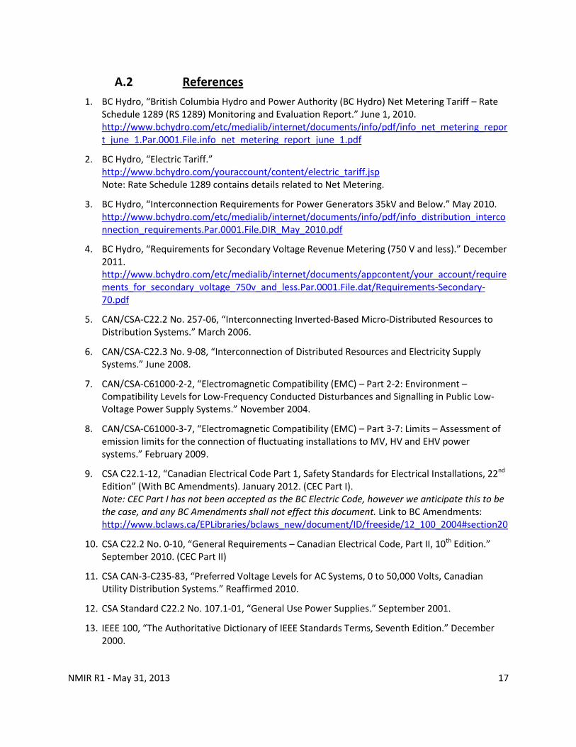
A.2 References
1. BC Hydro, “British Columbia Hydro and Power Authority (BC Hydro) Net Metering Tariff – Rate Schedule 1289 (RS 1289) Monitoring and Evaluation Report.” June 1, 2010. http://www.bchydro.com/etc/medialib/internet/documents/info/pdf/info_net_metering_report_june_1.Par.0001.File.info_net_metering_report_june_1.pdf
2. BC Hydro, “Electric Tariff.” http://www.bchydro.com/youraccount/content/electric_tariff.jsp Note: Rate Schedule 1289 contains details related to Net Metering.
3. BC Hydro, “Interconnection Requirements for Power Generators 35kV and Below.” May 2010. http://www.bchydro.com/etc/medialib/internet/documents/info/pdf/info_distribution_interconnection_requirements.Par.0001.File.DIR_May_2010.pdf
4. BC Hydro, “Requirements for Secondary Voltage Revenue Metering (750 V and less).” December 2011. http://www.bchydro.com/etc/medialib/internet/documents/appcontent/your_account/requirements_for_secondary_voltage_750v_and_less.Par.0001.File.dat/Requirements-Secondary-70.pdf
5. CAN/CSA-C22.2 No. 257-06, “Interconnecting Inverted-Based Micro-Distributed Resources to Distribution Systems.” March 2006.
6. CAN/CSA-C22.3 No. 9-08, “Interconnection of Distributed Resources and Electricity Supply Systems.” June 2008.
7. CAN/CSA-C61000-2-2, “Electromagnetic Compatibility (EMC) – Part 2-2: Environment – Compatibility Levels for Low-Frequency Conducted Disturbances and Signalling in Public Low-Voltage Power Supply Systems.” November 2004.
8. CAN/CSA-C61000-3-7, “Electromagnetic Compatibility (EMC) – Part 3-7: Limits – Assessment of emission limits for the connection of fluctuating installations to MV, HV and EHV power systems.” February 2009.
9. CSA C22.1-12, “Canadian Electrical Code Part 1, Safety Standards for Electrical Installations, 22nd Edition” (With BC Amendments). January 2012. (CEC Part I). Note: CEC Part I has not been accepted as the BC Electric Code, however we anticipate this to be the case, and any BC Amendments shall not effect this document. Link to BC Amendments: http://www.bclaws.ca/EPLibraries/bclaws_new/document/ID/freeside/12_100_2004#section20
10. CSA C22.2 No. 0-10, “General Requirements – Canadian Electrical Code, Part II, 10th Edition.” September 2010. (CEC Part II)
11. CSA CAN-3-C235-83, “Preferred Voltage Levels for AC Systems, 0 to 50,000 Volts, Canadian Utility Distribution Systems.” Reaffirmed 2010.
12. CSA Standard C22.2 No. 107.1-01, “General Use Power Supplies.” September 2001.
13. IEEE 100, “The Authoritative Dictionary of IEEE Standards Terms, Seventh Edition.” December 2000.

NMIR R1 - May 31, 2013 18
14. IEEE Std C37.90-2005, “IEEE Standard for Relays and Relay systems Associated with Electric Power Apparatus.” January 2006.

NMIR R1 - May 31, 2013 19
Appendix B: Figures and Single Line Diagrams
Figure B.1 – Relationship between DG System and Other Interconnection Terms (Source: Adapted From CAN/CSA-C22.2 No. 257-06 Figure 1)
BC Hydro Distribution System
DG
DG
Interconnection System (may be internal to DG)
DG’s Local Loads
DG’s Facility Boundary
PCC
DG System
Point of DG System Connection

NMIR R1 - May 31, 2013 20
Figure B.2 – Single Line Diagram of a Typical Inverter-Based Simple or Complex NM DG System (Source: Adapted From CAN/CSA-C22.2 No. 257-06 Figure B.1)
Notes: 1. Some BC Hydro customers have a separately metered sub panel for electric heating (i.e. E-Plus
panel - rate schedule RS 1105). No NM DG shall be connected to an E-plus panel. 2. This is a warning notice required by Clause 84-030 of the CEC Part I. BC Hydro requires that the
notice should be a permanent label suitable for outdoor conditions, with black letters on a white background, of a size and wording as indicated in Figure B.4. The notice must be mounted on the meter base (box), or if there is no meter base on the wall within 0.3 m (1 ft) of the meter.
3. Protection functions shown shall be internal for the inverter. 4. Elements shown with dashed line (- - -) are not typical for every installation. 5.

NMIR R1 - May 31, 2013 21
Figure B.3 - Single Line Diagram of a Typical Induction or Synchronous Generator-Based Complex NM DG System
(Source: Adapted From CAN/CSA-C22.3 No. 9-08 Figure A.1)
Notes: 1. Some BC Hydro customers have a separately metered sub panel for electric heating (i.e. E-Plus
panel - rate schedule RS 1105). No NM DG shall be connected to an E-plus panel. 2. This is a warning notice required by Clause 84-030 of the CEC Part I BC Hydro requires that the
notice should be a permanent label suitable for outdoor conditions, with black letters on a white background, of a size and wording as indicated in Figure B.4. In addition, where a DOO is required, an additional label “Potential for hazardous infeed – Refer to DOO” is required. The notice must be mounted on the meter base (box), or if there is no meter base on the wall within 0.3 m (1 ft) of the meter.
3. Protection schematic shown is for typical Complex Net Metering DG Systems. Refer to Section 4 for requirements on specific systems.

NMIR R1 - May 31, 2013 22
Figure B.4 - Warning Notice at BC Hydro Revenue Meter

NMIR R1 - May 31, 2013 23
Appendix C: Technical Tables
Table 1 - Distribution System Parameters .................................................................................................... 5 Table C.1 - Recommended Service Entrance Voltage Variation Limits ....................................................... 23 Table C.2 - Interconnection Protection Function Requirements for Inverter-Based DGs .......................... 24 Table C.3 – Inverter-Based DG Response to Abnormal Voltage Levels ...................................................... 25 Table C.4 – Maximum Harmonic Current Distortion .................................................................................. 25 Table C.6 - Frequency Operating Limits for Induction and Synchronous DGs ............................................ 26 Table C.7 - Induction and Synchronous Generator Response to Abnormal Voltage Levels ....................... 26 Table C.8 - Typical Measurement Location of Voltage and Frequency for Protection Functions .............. 27 Table D.1 – Field Verification Requirements For Complex NM Systems .................................................... 28 Table D.2 – Testing Summary for Inverter-Based Complex NM Systems ................................................... 28 Table D.3 – Testing Summary for Complex NM Systems using Induction or Synchronous Generators ..... 29 Table D.4 – Commissioning State Documentation Requirements for Complex NM Systems .................... 30
Table C.1 - Recommended Service Entrance Voltage Variation Limits (Source: CSA CAN-3-C235-83 Reaffirmed 2006 Table 3 and Section 6)
Nominal Voltage (Volts)
Service Entrance Voltage
Normal Extreme
Min Max Min Max
1-Phase 120/240 110/220 V 125/250 V 106/212 V 127/254 V
120/208 Y 112/194 V 125/216 V 110/190 V 127/220 V
347/600 Y 318/550 V 360/625 V 306/530 V 367/635 V
240 Delta 220 V 250 V 212 V 254 V
480 Delta 440 V 500 V 424 V 508 V
2400/4160 Grounded Wye -6% +6% -6% +6%
7200/12,470 Grounded Wye -6% +6% -6% +6%
14,400/24,940 Grounded Wye -6% +6% -6% +6%
19,920/34,500 Grounded Wye -6% +6% -6% +6%

NMIR R1 - May 31, 2013 24
Table C.2 - Interconnection Protection Function Requirements for Inverter-Based DGs (Source: Adapted from CAN/CSA-C22.2 No. 257-06 Table D.1)
Function 1 Phase 3 Phase
≤ 27 kW 27 kW – 50 kW
52 AC Disconnect Means
Y Y Y
Anti-islanding Y Y Y
25 Automatic Synchronizing4 Y Y Y
27 Under-voltage Trip
Y Y(3) A(3)
59 Over-voltage Trip Y Y(3) A(3)
50 Instantaneous Overcurrent5 Y Y(3) Y(3)
51 Timed Overcurrent5 Y Y(3) Y(3)
81/U Under-frequency Trip
Y Y A
81/O Over-frequency Trip
Y Y A
Notes:
1. For interconnection of 1 and 3 phase generation units connected at 600 volts or less in accordance with CEC Part I. Y = required, not adjustable; A = required, adjustable set points in accordance to Table C.3 and Table C.5.
2. Number of phases monitored shown in parentheses, e.g. (3). 3. For inverters with standalone capability. 4. 50/51 functions may be met by fuses or circuit breaker.

NMIR R1 - May 31, 2013 25
Table C.3 – Inverter-Based DG Response to Abnormal Voltage Levels
(Source: Adapted from CAN/CSA-C22.2 No. 257-06 Table C.2)
For DG Systems Rated ≤ 27 kW1 For DG Systems Rated > 27 kW1
Voltage Condition Max. Number of Cycles to
Disconnect Voltage Condition Max. Number of Cycles to
Disconnect
V < 50% 6 V < 50% 6
50% < V < 88% 120 50% ≤ V ≤ 88% 120
106% < V < 120% 120 106% < V < 110% Field adjustable trip may
be required3
V > 120% Instantaneous 110% ≤ V < 120% 120
V > 120% Instantaneous
Notes:
1. 27 kW was chosen as representing CSA’s 30 kVA x 0.9 power factor. 2. The CSA standard allows a wider normal voltage range than Table C.1 - to allow line regulation
equipment time to function. Field adjustable settings for Complex DG Systems may be required to improve protection. Field adjustable settings are to be adjusted by qualified personnel only.
Table C.4 – Maximum Harmonic Current Distortion (Source: CAN/CSA-C22.3 No. 9-08 Table 1)
Individual Harmonic Order, h
h < 11 11 ≤ h < 17 17 ≤ h < 23 23 ≤ h < 35 35 ≤ h Total Demand
Distortion
Distortion, Percentage of Current
4.0% 2.0% 1.5% 0.6% 0.3% 5.0%
Notes: The current specified in this Table is the greater of:
a) The Distribution System maximum load current integrated demand (15 or 30 min) without the DG; or
b) The DG unit rated current capacity, transformed at the PCC when a transformer exists between the DG unit and the PCC.
The maximum distortion values specified in this Table are for odd harmonics. To obtain maximum distortion values for even harmonics, the value in the corresponding h-range shall be multiplied by 25%

NMIR R1 - May 31, 2013 26
Table C.5 - Frequency Operating Limits for Inverter-Based DGs
(Source: Adapted From CAN/CSA-C22.2 No. 257-06 Table C.3)
DG System Capacity Frequency
Range (Hertz) Number of Cycles to Disconnect
≤ 27 kW F < 59.5 6
≤ 27 kW F > 60.5 6
> 27 kW 59.8 - 57 6 - 900
> 27 kW F > 60.5 6 - 900
Table C.6 - Frequency Operating Limits for Induction and Synchronous DGs
(Source: Adapted from CAN/CSA-C22.3 No. 9-08 Table 2 & 3)
DG System Capacity Adjustable Set Point, Hz Clearing Time (Adjustable Set Point)
≤ 27 kW 59.3–57 0.1–2 s
≤ 27 kW 60.7–61.7 0.1–2 s
> 27 kW 59.3-55.5 0.1 – 300 s
> 27 kW 60.7-63.5 0.1 – 180 s
Note: In some cases BC Hydro may specify two over-frequency and under-frequency set points.
Table C.7 - Induction and Synchronous Generator Response to Abnormal Voltage Levels
(Source: Adapted From CAN/CSA-C22.3 No. 9-08 Table 4)
Voltage Condition at PCC, % of Nominal Voltage1 Clearing Time2,3
V < 50% Not to exceed 0.16 s
50% ≤ V < 88% Instantaneous – 2 s
88% ≤ V < 106% Nominal Operation
106% < V ≤ 120% 2.0 s
V > 120% Not to exceed 0.16 s
Notes: 1. Nominal system voltage shall be in accordance with Clause 6.2 of CAN/CSA-C22.3 No.
9-08. 2. Specific clearing times within the ranges in this Table may be specified by BC Hydro.
Other clearing times or voltage ranges may be arranged through consultation between the DG Owner and BC Hydro.
3. Instantaneous means no intentional delay.

NMIR R1 - May 31, 2013 27
Table C.8 - Typical Measurement Location of Voltage and Frequency for Protection Functions
(Source: References Embedded in Table)
DG System Description
Transformer Winding
Configuration at Distribution
System Side
Generator Synchronization
Location4
Point of Measurement4
Reference
Inverter-based systems1 n/a n/a AC Output of Inverter n/a
Simple NM Generator n/a n/a AC Output of
Generator or Inverter
CAN/CSA-C22.3 No. 9-08 - Section
7.4.1.4
Complex NM Generator Connected at Secondary Voltage
n/a n/a AC Output of
Generator or Inverter
CAN/CSA-C22.3 No. 9-08 - Section
7.4.1.4
Connected at Primary Voltage2,3
Grounded Wye
Primary Side of Transformer
Primary Side of Transformer
CAN/CSA-C22.3 No. 9-08 - Fig A.2
Connected at Primary Voltage2,3
Grounded Wye
Secondary Side of Transformer
Primary Side of Transformer
CAN/CSA-C22.3 No. 9-08- Fig A.3
Connected at Primary Voltage 2,3 Delta
Primary Side of Transformer
Primary Side of Transformer
CAN/CSA-C22.3 No. 9-08- Fig A.4
Connected at Primary Voltage 2,3 Delta
Secondary Side of Transformer
Secondary Side of Transformer
CAN/CSA-C22.3 No. 9-08- Fig A.5
Notes: BC Hydro may approve exceptions to this table
1. Inverter-based systems generally have built-in protection functions which inherently measure at their AC terminals.
2. Primary Voltage connection is defined as having a voltage greater than 750 V at the PCC.
3. The protection function to detect ground faults on the Distribution System (59G) must measure the primary side of transformer.
4. Primary Side of the transformer is the side connected to the BC Hydro Distribution System.

NMIR R1 - May 31, 2013 28
Appendix D: Testing and Commissioning Tables
Table D.1 – Field Verification Requirements For Complex NM Systems
(Source: Adapted from BC Hydro Net Metering Tariff – Rate Schedule 1289 Monitoring and Evaluation Report)
Size Inverter-Based & Induction Generators Synchronous Generators
< 5 kW Not required Not required
5 kW to 10 kW May be required3 Required
> 10 kW Required Required
Notes: 1. Field verification is not required for Simple NM Systems 2. Field verification for Complex NM Systems is at the discretion of BC Hydro 3. Based on System Stiffness Ratio or Load Ratio
Required when System Stiffness Ratio is < 100 for inverter-based Complex NM Systems, < 50 for other Complex NM Systems
Required when the Load Ratio is < 2.0
Table D.2 – Testing Summary for Inverter-Based Complex NM Systems
(Source: Adapted from CAN/CSA-C22.2 No. 257-06 Section 7)
Test Step Test Procedure
1 Perform all recommended manufacturer testing
2 Functionally test all protective elements including:
2a - Anti-islanding (including time delay to re-energize)
2b - Inability to energize dead system
2c - Under- and over-voltage
2d - Under- and over-frequency
2e - Over-current (if applicable)
2f - Synchronizing controls (if applicable)
3 For battery equipped devices verify that protection settings are stored in non-volatile memory
4 For devices relying on battery power to trip, verify design to be fail-safe by disconnecting the battery and verifying the system ceases to energize the distribution system
5 Confirm all settings (magnitude & delay) are set to the BC Hydro accepted values and protected from changes

NMIR R1 - May 31, 2013 29
Table D.3 – Testing Summary for Complex NM Systems using Induction or Synchronous Generators
(Source: Adapted from CAN/CSA-C22.3 No. 9-08 Section 8)
Item Number Requirement
1 Visually confirm that the grounding coordination is compliant with manufacturer and BC Hydro requirements
2 Verify that the disconnecting means configured properly and operational
3 Verify that the polarities, burdens, and ratios of field-wired instrument transformers are correct and according to design
4 Verify that field-installed power and control wiring is in compliance with drawings and manufacturer requirements
5 On three-phase systems, verify that the phase rotation of the distribution system and the DG are compatible
6 Perform calibration checks of each protective relay (or the equivalent)
7 Test functionality of the protective relays (or the equivalent), circuit breakers, and telecommunications to verify that they operate as a system
8 Conduct load tests of protective relays (or the equivalent) immediately after initial energization
9 For DG systems which include a transformer, the ohmic value and connection of the transformer neutral impedance grounding device shall be verified as correct
10 Verify that, upon loss of power supply to the protective relays (or the equivalent), the protection scheme trips the circuit breaker
11 Verify the protective functions which ensure that DG ceases to energize the distribution system under the following conditions
11a - Under/over voltage
11b - Under/over frequency
11c - Protection scheme failure
11d - Any additional protection functions required for DG systems which include a
transformer
12 Voltage flicker (lighting variation visually noticeable? / voltage values & drop during starting)

NMIR R1 - May 31, 2013 30
Table D.4 – Commissioning State Documentation Requirements for Complex NM Systems
(Source: Adapted from CAN/CSA-C22.2 No. 257-06 Table D.2)
Item Number Requirement
1 Single Line Diagram indicating protection functions
2 Plot plan with location of disconnecting means and PCC
3 Nameplate information for the generator/source and inverter
4 For inverter-based DG systems, a description of any protection scheme external to the inverter
5 Manufacturer’s equipment data sheet
6 Protective function settings
7 Commissioning Report complete with protection settings shown to be set to magnitude and time delays accepted by BC Hydro and protected from changes
8 Photographs of the DG System installation, showing equipment nameplates, disconnect means, revenue meter with warning label and the main AC panel

NMIR R1 - May 31, 2013 31
Appendix E: Application Data Requirements
Applicant Information:
Company Name Last Name First Name Phone Email Street Address City Postal Code Signature GST # (if applicable)
DG Site Information:
Site Name Street Address City Postal Code Service Voltage (V) BC Hydro Account # BC Hydro Meter Number # Is this application for a new Net Metering Generation System, of a modification of an existing
system [New/ Modification] Contractor or Installer Information:
Company Name Last Name First Name Phone Email Street Address City Province Postal Code

NMIR R1 - May 31, 2013 32
Information for Simple Net Metering Generator Systems: A project will be considered as a Simple NM if both the following are met:
- Inverter system certified to the requirements of CSA C22.2 No. 107.1-01 for utility interconnections - Aggregate nameplate rating of 27 kW or less - Has self-contained revenue metering
Inverter certified under CSA C22.2 No. 107.1-01 [Y/N] Inverter Manufacturer Inverter Model Inverter Nameplate Capacity (kW) Inverter Output Voltage (V) Number of Phases [Single/Three] Energy Source [Solar/Wind/Hydro/Other(specify)] Installed Capacity of Energy Source (kW) Does the system include Battery Storage [N/Y (specify)]
Information for Complex Net Metering Generator Systems: A project will be considered as a Complex NM if any of the following are met:
- Inverter-based system not certified to the requirements of CSA C22.2 No. 107.1-01 for utility interconnections - Aggregate nameplate rating of more than 27 kW - Induction or synchronous generator - Has instrument transformer revenue metering
Synchronous or Induction Generator System: Generator Type [Induction/Synchronous] Generator Manufacturer Generator Model Generator Nameplate Capacity (kW) Generator Power Factor (p.f.) Generator Output Voltage (V) Number of Phases [Single/Three] Generator Subtransient Reactance (Xd”): Energy Source [Solar/Wind/Hydro/Wind/Other (specify)] Protection Relays (manufacturer, model, functions, settings) For Induction Machines only - Declaration that machine is not self-excited [Y/N] For Induction Machines only – Power Factor Correction Capacitor size (KVAR)
Inverter-Based System: Inverter certified under CSA C22.2 No. 107.1-01 [Y/N] Inverter Manufacturer Inverter Model Inverter Nameplate Capacity (kW) Inverter Output Voltage (V) Number of Phases [Single/Three] Energy Source [Solar/Wind/Hydro/Other(specify)] Installed Capacity of Energy Source (kW) Does the system include Battery Storage [N/Y (specify)]

NMIR R1 - May 31, 2013 33
Additional Documentation Required for Complex Net Metering Generator Systems:
1. Single Line Diagram showing: Project Title, Date, Revision Number, Site Address, Name of Person or Firm that prepared
drawing Differentiation between new and existing equipment (Cloud or dividing line) All switches, breakers, and relays shall have distinct identifiers or names Service Entrance equipment BC Hydro revenue meter and, if applicable, revenue metering instrument transformers and E-
Plus Meter All electrical equipment between the Service Entrance and the generator (switches, breakers,
cables, etc.). Location of DG Disconnect means Location of warning labels as required by CEC Part I Generator/Inverter nameplate information and model numbers
2. Site Plan showing: Project Title, Date, Revision Number, Site Address, Name of Person or Firm that prepared
drawing Plan view of the site, with nearby roads Location of PCC, BC Hydro Metering, Electrical Panels, and generator/inverter. Location of DG Disconnect Means Equipment names, which match the single line drawing Site Plan does not need to be to scale
3. Additional Documentation for Induction or Synchronous Generators: Generator data sheet showing nameplate information Description of Project Protection and Control System (Logic block diagram or narrative) Description of Protection failure scheme (See section 4.2.3) Protection Single Line Diagram showing: Protective relays, relay functions, and protection
functions that trip mechanical equipment (such as a protection function failure scheme) Protection Relay data sheet and Protective Relay Settings Description of the generator starting sequence (logic block diagram or narrative)
NMIR R1 - May 31, 2013 34
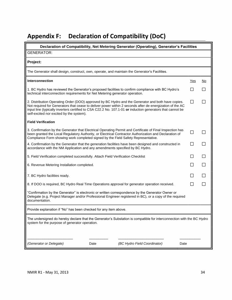
Appendix F: Declaration of Compatibility (DoC)
Declaration of Compatibility, Net Metering Generator (Operating), Generator’s Facilities
GENERATOR:
Project:
The Generator shall design, construct, own, operate, and maintain the Generator’s Facilities.
Interconnection Yes No
1. BC Hydro has reviewed the Generator’s proposed facilities to confirm compliance with BC Hydro’s technical interconnection requirements for Net Metering generator operation.
2. Distribution Operating Order (DOO) approved by BC Hydro and the Generator and both have copies. Not required for Generators that cease to deliver power within 2 seconds after de-energization of the AC input line (typically inverters certified to CSA C22.2 No. 107.1-01 or induction generators that cannot be
self-excited nor excited by the system).
Field Verification
3. Confirmation by the Generator that Electrical Operating Permit and Certificate of Final Inspection has been granted the Local Regulatory Authority, or Electrical Contractor Authorization and Declaration of Compliance Form showing work completed signed by the Field Safety Representative.
4. Confirmation by the Generator that the generation facilities have been designed and constructed in accordance with the NM Application and any amendments specified by BC Hydro.
5. Field Verification completed successfully. Attach Field Verification Checklist
6. Revenue Metering Installation completed.
7. BC Hydro facilities ready.
8. If DOO is required, BC Hydro Real Time Operations approval for generator operation received.
“Confirmation by the Generator” is electronic or written correspondence by the Generator Owner or Delegate (e.g. Project Manager and/or Professional Engineer registered in BC), or a copy of the required documentation.
Provide explanation if “No” has been checked for any item above.
The undersigned do hereby declare that the Generator’s Substation is compatible for interconnection with the BC Hydro system for the purpose of generator operation.
________________________
(Generator or Delegate)
__________
Date
________________________
(BC Hydro Field Coordinator)
___________
Date