Embed Size (px)
Citation preview
Nested Buddy System: A New Block AddressAllocation Scheme for ISPs and IaaS Providers
Michael B. Crouse, H.T. KungJohn A. Paulson School of Engineering and Applied Sciences
Harvard UniversityCambridge, MA 02138
Email: [email protected], [email protected]
Abstract—We propose a novel block address allocationmethod, called the nested buddy system, which can make useof wasted areas in the classical buddy system due to internalfragmentation. While achieving high utilization of address space,our new scheme supports efficient address matching for routersin packet forwarding and for network middleboxes in packetfiltering. Specifically, the scheme uses just one prefix rule foreach allocated address block in a packet routing/filtering table.We show by analysis and simulation that the increased addressutilization can lead to significant reduction in the probabilityof a denial-of-service under bursty address allocation requests.In contrast, the classical buddy system requires the aggregationof many requests over time to smooth out demand, resulting inservice delays undesirable to end users. Our solution is applicableto ISPs in serving mobile users carrying many network connectedIoT devices and IasS providers in the cloud in serving tenantswith dynamically varying demands for network addresses.
Keywords—Networking, IP allocation, Cloud, ISP, IaaS, IoT
I. INTRODUCTIONWe address a fundamental conflict in large-scale resource
allocation, namely, efficient allocation of shared resourcesversus ease in managing the allocated resources. Specifically,we propose a novel block address allocation scheme, the nestedbuddy system, which exhibits desirable trade-offs betweenthese two goals. Compared to previous solutions based on thestandard buddy system, our solution can increase address-spaceutilization by more than 50% while requiring only one prefixrule per allocated address block for routing and firewall tableentries.
We show by analysis and simulation that the increased uti-lization of address space can lead to a significant reduction inthe possibility of denial-of-service due to depletion of addressresources resulting from bursty demands. We illustrate how oursolution can benefit Internet Service Providers (ISPs) in serv-ing mobile users carrying many network connected Internetof Things (IoT) devices and Infrastructure-as-a-Service (IasS)providers in the cloud for serving tenants with dynamicallyvarying demands on network addresses.
The contributions of the paper are as follows:1) The proposed nested buddy system for block address
allocation (Section IV-C).2) Analysis on the utilization of address space under
the classical buddy system (Section IV-B) and hownested buddy system can improve upon it.
3) An overlapping allocation scheme which allows useof only one prefix rule per allocated address block,and an efficient Ternary Content Addressable Mem-ory (TCAM) implementation for resolving the allo-
cation ambiguity (Section IV-C2).4) Validation by numerical simulations and analysis for
arrivals and frees of block address requests with sizesunder various distributions (Sections V,VI and VII).
5) Formulation of address block allocation problemsfor achieving high address-space utilization whileminimizing the required number of rules per allocatedblock in packet routing and filtering tables for bothISPs serving mobile users with many IoT devices(Section VII) and IaaS service providers servingtenants with dynamic requests of network addresses(Section VI).
II. RELATED WORKProviding optimizations for high-speed packet matching
and forwarding consists of many different levels of abstraction.In order to perform filtering and routing at a line rate ofmultiple gigabits per second, optimizations are crucial; asurvey of several approaches can be found here [1], amongthem are rule compression, re-ordering and rule-representationstructuring [2], [3], [4]. Others have focused on designingoverlapping and searching schemes for prefix specificationused in hardware accelerators such as TCAMs [5].
The set of optimizations most similar to our work are effi-cient representations of packet matching rule sets for hardwareimplementation. Srinivasan et. al. showed that many networklevel packet filters that rely on source and destination addressescan be easily represented as a set of prefix entries that are anideal fit for TCAM implementations [6]. Another optimizationis in the representation of the rules (entries) themselves usingencoding schemes to compress the rules within the limitedbudget of a Content Address Memory block [4].
Our work focuses on block allocation schemes, specificallythe buddy system allocation scheme which was describedby Knuth [7]. A survey of allocation schemes as well asworkload simulation specifically for memory systems providesa complete treatment of different approaches and types of allo-cators [8]. Our nested structure leverages the basic premise ofthe buddy scheme but alters it to suit address block allocationsidentifiable by address prefixes for fast packet classificationwith TCAM. As far as we know, our propsed nested buddysystem, which can minimize waste in block address allocationdue to fragmentation and the number of required entries fortheir representation, is new.
III. MOTIVATING APPLICATION SCENARIOSWe consider major trends associated with the increase of
demand, and exhaustion, of public IPv4 addresses, in regards
to the IoT and IaaS. The increase in number of devices andtheir requirement of routable addresses introduces the need forhighly optimized design of the allocation and management ofpublic addresses in order to increase address space utilizationwhile minimizing the cost of packet routing and filtering.
A. IaaS Providers in the CloudConsider IasS providers which provide tenants’ appli-
cations with external-facing public IP addresses. Given thescarcity of IPv4 addresses, today’s service providers usuallydo not have a single, large contiguous address space [9].Instead, they use an aggregation of address blocks of varioussizes, accumulated over the entire IPv4 address space [10],[11]. When a particular address block is exhausted, the serviceprovider will need to allocate tenants to other blocks, possiblyeven from other registration regions which can introduce poorperformance as well as unseen cybersecurity. It is thereforecritical that address allocation schemes have high utilizationto limit the chance of address-space exhaustion.1
Address-space utilization must be balanced with ease ofmanagement of allocated addresses, especially in the numberof required rules for routing and filtering tables in routersand firewall middleboxes. For high-speed, line-rate packet pro-cessing, hardware acceleration (e.g., TCAM) is often utilizedwhich entails expensive circuitry and high power consumptionfor which it is crucial to minimize the number of installedrules. For example, use of just one TCAM entry for eachallocated address block (i.e., one rule per block) is highlydesirable. Use of entries logarithmic to the block size wouldbe considered as prohibitively expensive [5], [6]. For thesereasons, addresses should be allocated in blocks rather thanindividually to allow a single rule to represent a block ofaddresses.
Furthermore, for efficient address matching, it is preferableto route or filter based on address prefixes as in conventional IProuting. The classical buddy system is a standard block addressallocation scheme that supports prefix matching, however,it generally incurs substantial waste due to fragmentation,inducing a degradation in terms of address-space utilization.The nested buddy system introduced in this paper aims at im-proving address-space utilization while requiring a minimumnumber of prefix rules for router and firewall tables.
B. ISPs for Mobile Users with IoT DevicesA main technology trend in the past several years has
been the increased commercial availability of a wide varietyof wearables, which together with other sensing and controldevices, form the Internet of Things (IoT). We consider ascenario where a mobile user may carry many such networkconnected wearables while moving from location to location.When a user arrives at a foreign network, the network willneed to provide routing and firewall services for his or herdevices, in the style of mobile IP [12]. For easy management, itwould be desirable to manage the devices associated with eachuser as a single address block subject to the same forwardingand filtering rules associated with the user. Therefore, it isimportant to allocate such address blocks efficiently to avoidan unnecessary denial-of-service due to depletion of availableaddresses, especially when users arrive in bursts.
1Note that for IPv6, which has abundant IP addresses, efficient ad-dress allocation remains critical, for line-rate hardware-assisted packet filter-ing/matching; see Section III-B.
128
512
1 2 3 4 5 6 7 8
256
512 512 512 512 512 512
128
64
64
256
64
64
128
128
64
64
128
128
128
64
128
128
64
128
128
128
128
128
128
128
128
128
256
Allocated
Internal Fragment
Free
Coalesce Buddy1024
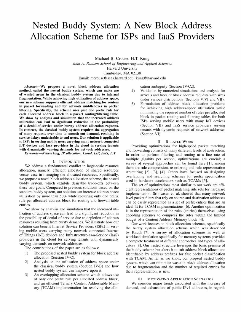
Fig. 1: Illustration of the classical buddy allocation systemmanaging a resource of 1024 items. The orange areas withinred allocations represent internal fragmentation. Buddies canonly be recombined with both are free as in Step 5 and 7.
IoT devices will benefit from the emergence of IPv6 whichhas a substantial 128-bit address space, where every devicecan literally be assigned to a unique address as opposed toIPv4’s 32-bit addresses. Unfortunately, IPv6 does not meanthat address allocation is no longer a challenge. In fact, in orderto route/filter packets at high speeds via hardware circuits suchas TCAM, we still need to associate a logical group of devicessuch as those carried by a mobile user with a prefix addressstring of only a relatively small number of bits (e.g., 16 or24). We can in general only expect gradual improvements inthe implementation cost and energy consumption of hardwareaccelerators such as TCAM. These incremental improvementswill likely be overwhelmed by new demands such as thoseimposed by IoT devices. We project the problem of efficientblock address allocation addressed in this paper will only gainimportance over coming years.
IV. BLOCK ADDRESS ALLOCATION SCHEMESTo be self contained, this section briefly reviews the basics
of block address allocation schemes. An efficient allocationscheme must have low management cost while minimizing theamount of address space waste introduced when serving allo-cation requests. We adopt the terminology from the memorymanagement literature for this discussion.
The wasted space introduced by an allocation scheme isreferred to as fragmentation of which there are two types:internal and external. Internal fragmentation is the resultof over-provisioning when performing an allocation for arequest generally in order to provide easier management of theallocated block. External fragmentation refers to wasted blocksresulting from a sequence of allocations and frees yielding“islands” of small, unallocated blocks, of sizes too small foruse by the application.
In addition, we are concerned with the cost of usingthe blocks once they are allocated as in the case of packetrouting and filtering. A well structured, hierarchical allocationof IP addresses can greatly reduce the number of entries inthe routing/filtering table necessary for specifying the desirednetwork behavior, e.g., packet routing or filtering. We are
A
C
B
b-1 bits
b-2 bits
b-3 bits
Occupied (A)
Nested Buddy Block B (b-2) bits
Available for Allocation
Wasted
b bits
Nested Buddy Block C (b-3) bits
Available for Allocation
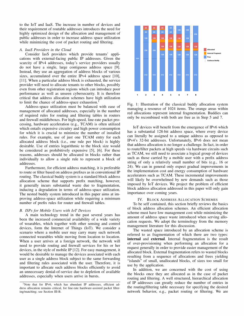
Fig. 2: Nested buddy system allocation utilizes the unoccupiedportion of a buddy block allocation (block for A) from thebottom up. Each nested buddy block is the largest power oftwo block beginning from the bottom that can be allocatedwithout overlapping with occupied region in red.
interested in minimizing the the cost in terms of number ofentries necessary for compact representation of each allocationblock. Thus the goal of an allocation scheme is to minimizethe amount of fragmentation of the resource while providingminimal cost in representing the allocations made.
A. Buddy System AllocationThe address allocation scheme proposed by this paper
builds on top of the classical buddy system. The general buddysystem allocation handles dynamic requests by recursivelydividing the resource until an appropriate size block is reached.The system was originally specified by Knuth in [7] and a fulltreatment of block allocation schemes, including the buddysystem, is found in the literature (e.g., [8], [13]). The buddysystem is particularly relevant to the subject of this paperbecause it embeds the basics of prefix-based address schemeswidely used in Internet routing by only allocating address-prefix identifiable blocks.
The most common form of the buddy system divides theresource into two equal parts at each recursive step, alwaysyielding block sizes in powers of two. Each pair of blocks ata given size are referred to as “buddies”; when both are free,they are recombined to form a single block of twice the size.Figure 1 depicts a sequence of requests and frees using thebuddy system. The buddy system’s requirement of allocatedblocks being identifiable by address prefixes results in singleprefix entries per allocation, i.e., each block allocation can berepresented by a single rule or, in TCAM implementations, asingle TCAM entry.
Unfortunately, the cost of allocating blocks residing onprefix boundaries the potential of over-allocating a block couldwaste up to 50% of the addresses. For many applicationdomains, such as IP address allocation for IaaS providers andISPs considered in this paper, this amount of wasted addressspace due to internal fragmentation is too costly.
Fragment
b-2 bits(free)
b-3 bits
b-1 bits(allocated)
b-2 bits (allocated)
b-3 bits(free)
b-1 bits(allocated)
b-2 bits (allocated)
b-3 bits(allocated)
b-1 bits(allocated)
b-4 bits(allocated)
b-4 bits(allocated)
A A1
A2
B B
C
A1
A2
Fragment
1 2 3
C
B
C
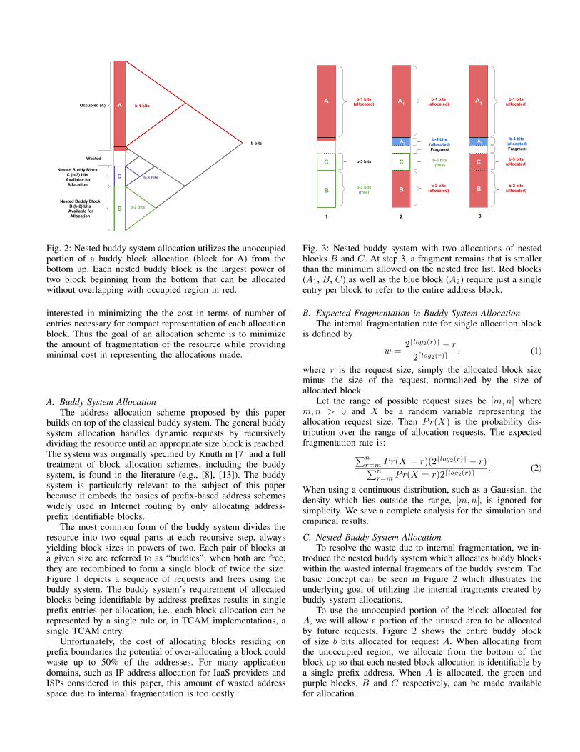
Fig. 3: Nested buddy system with two allocations of nestedblocks B and C. At step 3, a fragment remains that is smallerthan the minimum allowed on the nested free list. Red blocks(A1, B, C) as well as the blue block (A2) require just a singleentry per block to refer to the entire address block.
B. Expected Fragmentation in Buddy System AllocationThe internal fragmentation rate for single allocation block
is defined by
w =2dlog2(r)e � r
2dlog2(r)e. (1)
where r is the request size, simply the allocated block sizeminus the size of the request, normalized by the size ofallocated block.
Let the range of possible request sizes be [m,n] wherem,n > 0 and X be a random variable representing theallocation request size. Then Pr(X) is the probability dis-tribution over the range of allocation requests. The expectedfragmentation rate is:
Pn
r=m
Pr(X = r)(2dlog2(r)e � r)Pn
r=m
Pr(X = r)2dlog2(r)e. (2)
When using a continuous distribution, such as a Gaussian, thedensity which lies outside the range, [m,n], is ignored forsimplicity. We save a complete analysis for the simulation andempirical results.
C. Nested Buddy System AllocationTo resolve the waste due to internal fragmentation, we in-
troduce the nested buddy system which allocates buddy blockswithin the wasted internal fragments of the buddy system. Thebasic concept can be seen in Figure 2 which illustrates theunderlying goal of utilizing the internal fragments created bybuddy system allocations.
To use the unoccupied portion of the block allocated forA, we will allow a portion of the unused area to be allocatedby future requests. Figure 2 shows the entire buddy blockof size b bits allocated for request A. When allocating fromthe unoccupied region, we allocate from the bottom of theblock up so that each nested block allocation is identifiable bya single prefix address. When A is allocated, the green andpurple blocks, B and C respectively, can be made availablefor allocation.
A
1
A
2
1
b-2 bits(1 entry)
b-3 bits(1 entry)
b-1 bits(1 entry)
Fig. 4: Example of the potential cost of allocating a nestedblock for a minimum size, assuming that allocated blocks donot overlap. Allowing a nested allocation B, in green, to bearbitrarily small can introduce a high cost in the number ofprefixes for representing A exactly.
Figure 3 illustrates the allocation of nested blocks andtheir allocation over a sequence of three requests. If a requestis made which is larger than all available blocks, we splitthe request into multiple block allocations, each block is stillidentifiable by a single prefix entry.
We study the performance of our nested buddy systemby first assuming that allocated blocks do not overlap. Wethen describe an overlapping scheme which can achieve highaddress-space utilization while still requiring only one entryper allocated block.
1) Non-overlapping Scheme: Figure 4 illustrates the worsecase in terms of total entries for allocation of A and B withinthe same root block. When A is initially allocated, it onlyrequires a single entry to represent the whole root block, shownby the orange block. In step 2, when a request is filled withthe nested block in green it will require the prefix entries forA to be expanded, shown by the b� 1 orange lines.
Based on the tree representation of Figure 2, we can provethe following claims. Their proofs are straightforward but weomit them due to space constraints.
Claim 1 Suppose that allocation blocks cannot overlap. Thenthe number of entries in the worst case for allocating A andB into a root block of size b bits is O(b).
That is, the number of entries required to represent twoblocks within a root block in the worst case is logarithmicin the size of the block in order to specify A and B withoutthe prefix entries correspond to overlapping address blocks.Scaling the number of entries logarithmically with the size ofthe block is considered to be prohibitively expensive as notedin Section I-A.
Let A2 correspond to the part of A’s occupancy thatexpands over the b�1 bit boundary which is shown in Figure 3in blue. Let b
A2 and bB
be the size in bits for A and B,respectively. We state the following:
Claim 2 A root block with allocations A and B can eachbe represented exactly with at most two entries if (b � 1) �(b
A2 � bB
) � 0.
This is simply to state that if A2 and B can each be rep-resented by a single power of two block without overlappingthen the number of entries is equal to the number of blocks,
A
1
A
2
B1 entry
1 entry 1 entry
Query - qfrag
Query - qA
Query - qB
0 x x x x x x
0 x x x x x x
0 1 1 x x x x
C
0 x x x x x x
0 1 1 x x x x
0 1 0 1 x x x
M0
M0
M1
M0
M1
M2
M0 = 1 ⇒ A
M0M1’ = 1 ⇒ A M1 = 1 ⇒ B
M0(M1’ + M2’) = 1 ⇒ A M1 = 1 ⇒ B M2 = 1 ⇒ C
1 entry
0
32
64
40
48
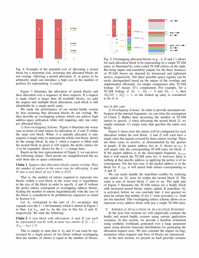
Fig. 5: Overlapping allocated blocks (e.g., A,B and C) allowsfor each allocation block to be representing by a single TCAMentry, as illustrated by color-coded TCAM entries on the right.Bit-string inputs and matchline outputs for the three instancesof TCAM shown are denoted by downward and rightwardarrows, respectively. The three possible query regions can beeasily distinguished based on the nature of the overlaps andimplemented efficiently via simple comparison after TCAMlookup. M 0 means M ’s complement. For example, for aTCAM lookup, if M1 = M2 = 0 and M0 = 1, thenM0(M 0
1 + M 02) = 1, so the looked up entry is considered
to be in A.
two in this case.2) Overlapping Scheme: In order to provide maximum uti-
lization of the internal fragments, we can relax the assumptionof Claim 2. Rather than increasing the number of TCAMentries to specify A when allocating the nested block B, wesimply maintain A’s single entry that specifies the entire rootblock.
Figure 5 shows how the entries will be configured for eachallocation within the root block. A and B will each have asingle entry but regions covered by these entries overlap. Thereare three cases to resolve, as demonstrated by the queriesin purple. If the packet address lies in A, shown as q
A
, itwill match only the corresponding TCAM entry for block A.If the packet address is in the unoccupied fragment, q
frag
,then it will match the TCAM entry for A; however, there isnothing at that specific address so applying the policy is of noconsequence. For the last case, if the packet address is in theblock for B, q
B
, it will match both entries corresponding toA and B.
We can easily handle the matchline conflict by realizingany match on M1 must lie within the nested block B. Thesame is true of nested block C and so on. The right partof Figure 5 illustrates the TCAM entries for a buddy blockwith increased nested blocks entries added. If matchline M0
is activated, before we can conclude that A was queried wemust be certain that neither B nor C were activated, i.e., bothare not matched. This overlapping entries scheme allows us torepresent every address block with just a single TCAM entry.
V. EMPIRICAL EVALUATION OF ALLOCATION SCHEMESIn the next four sections we will empirically evaluate the
buddy and nested buddy systems using various applicationscenarios. In this section, we provide a baseline evaluationusing synthetic workloads generated over a large parameterspace using discrete Gaussian distributions for generating theallocation request sizes. We also consider the impact on frag-mentation when requests and frees of blocks are intermixed.
In the next section, we present an IaaS provider scenario
for allocating their public IP address space among their manytenants and the impact of auto-scaling [11], [10]. Finally, inSections VII and VIII, we will present a personal IoT scenarioin which users, along with their connected devices, movebetween ISPs.
To evaluate the the buddy and proposed nested buddysystems for block IP address allocation, we have constructed asimulator for serving requests and frees for a large IP addressspace. The simulator is implemented in Python and runs on anIntel Core-i7 3.6 GHz processor with 4 hyper-threaded coresand 16 GB RAM under Ubuntu 14.04 LTS. Each simulationconfiguration was run 500 times and results were averaged.The size of the address space to be allocated is a /14 network(16K addresses) for all presented results. We have found thatlarger address spaces have similar trends but were slower toevaluate. 2
A. Baseline Evaluation of Allocation FragmentationWe now present an empirical comparison with the theoret-
ical model described in Section IV-B for the classical buddysystem and the improved performance of our proposed nestedbuddy system. We consider a discrete Gaussian distributionfor our baseline analysis with increasing variance. We will setthe mean of the distribution to be 16 for the figures presentedin this section.3 The first set of experiments are performedwithout any de-allocations, referred to as freeing, in order tofocus on the fragmentation in a simple case as modeled inSection IV-B.
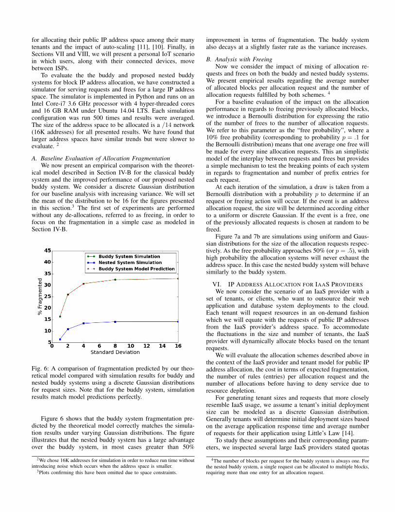
Fig. 6: A comparison of fragmentation predicted by our theo-retical model compared with simulation results for buddy andnested buddy systems using a discrete Gaussian distributionsfor request sizes. Note that for the buddy system, simulationresults match model predictions perfectly.
Figure 6 shows that the buddy system fragmentation pre-dicted by the theoretical model correctly matches the simula-tion results under varying Gaussian distributions. The figureillustrates that the nested buddy system has a large advantageover the buddy system, in most cases greater than 50%
2We chose 16K addresses for simulation in order to reduce run time withoutintroducing noise which occurs when the address space is smaller.
3Plots confirming this have been omitted due to space constraints.
improvement in terms of fragmentation. The buddy systemalso decays at a slightly faster rate as the variance increases.
B. Analysis with FreeingNow we consider the impact of mixing of allocation re-
quests and frees on both the buddy and nested buddy systems.We present empirical results regarding the average numberof allocated blocks per allocation request and the number ofallocation requests fulfilled by both schemes. 4
For a baseline evaluation of the impact on the allocationperformance in regards to freeing previously allocated blocks,we introduce a Bernoulli distribution for expressing the ratioof the number of frees to the number of allocation requests.We refer to this parameter as the “free probability”, where a10% free probability (corresponding to probability p = .1 forthe Bernoulli distribution) means that one average one free willbe made for every nine allocation requests. This an simplisticmodel of the interplay between requests and frees but providesa simple mechanism to test the breaking points of each systemin regards to fragmentation and number of prefix entries foreach request.
At each iteration of the simulation, a draw is taken from aBernoulli distribution with a probability p to determine if anrequest or freeing action will occur. If the event is an addressallocation request, the size will be determined according eitherto a uniform or discrete Gaussian. If the event is a free, oneof the previously allocated requests is chosen at random to befreed.
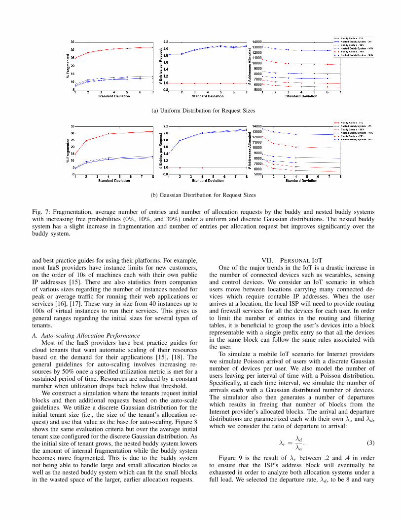
Figure 7a and 7b are simulations using uniform and Gaus-sian distributions for the size of the allocation requests respec-tively. As the free probability approaches 50% (or p = .5), withhigh probability the allocation systems will never exhaust theaddress space. In this case the nested buddy system will behavesimilarly to the buddy system.
VI. IP ADDRESS ALLOCATION FOR IAAS PROVIDERSWe now consider the scenario of an IaaS provider with a
set of tenants, or clients, who want to outsource their webapplication and database system deployments to the cloud.Each tenant will request resources in an on-demand fashionwhich we will equate with the requests of public IP addressesfrom the IaaS provider’s address space. To accommodatethe fluctuations in the size and number of tenants, the IaaSprovider will dynamically allocate blocks based on the tenantrequests.
We will evaluate the allocation schemes described above inthe context of the IaaS provider and tenant model for public IPaddress allocation, the cost in terms of expected fragmentation,the number of rules (entries) per allocation request and thenumber of allocations before having to deny service due toresource depletion.
For generating tenant sizes and requests that more closelyresemble IaaS usage, we assume a tenant’s initial deploymentsize can be modeled as a discrete Gaussian distribution.Generally tenants will determine initial deployment sizes basedon the average application response time and average numberof requests for their application using Little’s Law [14].
To study these assumptions and their corresponding param-eters, we inspected several large IaaS providers stated quotas
4The number of blocks per request for the buddy system is always one. Forthe nested buddy system, a single request can be allocated to multiple blocks,requiring more than one entry for an allocation request.
(a) Uniform Distribution for Request Sizes
(b) Gaussian Distribution for Request Sizes
Fig. 7: Fragmentation, average number of entries and number of allocation requests by the buddy and nested buddy systemswith increasing free probabilities (0%, 10%, and 30%) under a uniform and discrete Gaussian distributions. The nested buddysystem has a slight increase in fragmentation and number of entries per allocation request but improves significantly over thebuddy system.
and best practice guides for using their platforms. For example,most IaaS providers have instance limits for new customers,on the order of 10s of machines each with their own publicIP addresses [15]. There are also statistics from companiesof various sizes regarding the number of instances needed forpeak or average traffic for running their web applications orservices [16], [17]. These vary in size from 40 instances up to100s of virtual instances to run their services. This gives usgeneral ranges regarding the initial sizes for several types oftenants.A. Auto-scaling Allocation Performance
Most of the IaaS providers have best practice guides forcloud tenants that want automatic scaling of their resourcesbased on the demand for their applications [15], [18]. Thegeneral guidelines for auto-scaling involves increasing re-sources by 50% once a specified utilization metric is met for asustained period of time. Resources are reduced by a constantnumber when utilization drops back below that threshold.
We construct a simulation where the tenants request initialblocks and then additional requests based on the auto-scaleguidelines. We utilize a discrete Gaussian distribution for theinitial tenant size (i.e., the size of the tenant’s allocation re-quest) and use that value as the base for auto-scaling. Figure 8shows the same evaluation criteria but over the average initialtenant size configured for the discrete Gaussian distribution. Asthe initial size of tenant grows, the nested buddy system lowersthe amount of internal fragmentation while the buddy systembecomes more fragmented. This is due to the buddy systemnot being able to handle large and small allocation blocks aswell as the nested buddy system which can fit the small blocksin the wasted space of the larger, earlier allocation requests.
VII. PERSONAL IOTOne of the major trends in the IoT is a drastic increase in
the number of connected devices such as wearables, sensingand control devices. We consider an IoT scenario in whichusers move between locations carrying many connected de-vices which require routable IP addresses. When the userarrives at a location, the local ISP will need to provide routingand firewall services for all the devices for each user. In orderto limit the number of entries in the routing and filteringtables, it is beneficial to group the user’s devices into a blockrepresentable with a single prefix entry so that all the devicesin the same block can follow the same rules associated withthe user.
To simulate a mobile IoT scenario for Internet providerswe simulate Poisson arrival of users with a discrete Gaussiannumber of devices per user. We also model the number ofusers leaving per interval of time with a Poisson distribution.Specifically, at each time interval, we simulate the number ofarrivals each with a Gaussian distributed number of devices.The simulator also then generates a number of departureswhich results in freeing that number of blocks from theInternet provider’s allocated blocks. The arrival and departuredistributions are parametrized each with their own �
a
and �d
,which we consider the ratio of departure to arrival:
�r
=�d
�a
. (3)
Figure 9 is the result of �r
between .2 and .4 in orderto ensure that the ISP’s address block will eventually beexhausted in order to analyze both allocation systems under afull load. We selected the departure rate, �
d
, to be 8 and vary
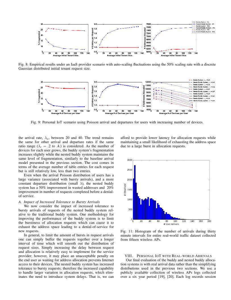
Fig. 8: Empirical results under an IaaS provider scenario with auto-scaling fluctuations using the 50% scaling rate with a discreteGaussian distributed initial tenant request size.
Fig. 9: Personal IoT scenario using Poisson arrival and departures for users with increasing number of devices.
the arrival rate, �a
, between 20 and 40. The trend remainsthe same for other arrival and departure rates if the sameratio range (�
r
= .2 to .4.) is considered. As the number ofdevices for each user grows, the buddy system’s fragmentationincreases slightly while the nested buddy system maintains thesame level of fragmentation, similarly to the baseline arrivalmodel presented in the previous section. The cost comes interms of the average number of table entries for each requestbut is still relatively low, less than two entries.
Even when the arrival Poisson distribution of users has alarge variance (associated with bursty arrivals), and a moreconstant departure distribution (small �), the nested buddysystem has a 50% improvement in wasted addresses and 20%improvement in number of requests completed before a denial-of-service.
A. Impact of Increased Tolerance to Bursty ArrivalsWe now consider the impact of increased tolerance to
bursty arrivals of requests of the nested buddy system rel-ative to the traditional buddy system. One methodology forimproving the performance of the buddy system is to limitthe burstiness of allocation requests which can cause it toexhaust the address space leading to a denial-of-service fornew requests.
In general, to limit the amount of bursts in request arrivalsone can simply buffer the requests together over a longerinterval of time which will smooth out the distribution ofrequest sizes. Simply increasing the delay between requestand allocation is relatively easy to implement for the serviceprovider; however, it may place an unacceptable penalty onthe end user as waiting for address allocation prevents Internetaccess to their devices. The nested buddy system has increasedtolerance to bursty requests; therefore the increased capabilityto handle larger variation in allocation requests, which elim-inates the need to introduce system delays. That is, we can
afford to provide lower latency for allocation requests whilemaintaining a small likelihood of exhausting the address spacedue to a large burst in allocation requests.
Fig. 11: Histogram of the number of arrivals during thirtyminute intervals for entire real-world traffic dataset collectedfrom fifteen wireless APs.
VIII. PERSONAL IOT WITH REAL-WORLD ARRIVALSOur final evaluation of the buddy and nested buddy alloca-
tion systems is with real arrival data rather than the simplifyingdistributions used in the previous two sections. We use apublicly available collection of wireless APs logs collectedover a six year period [19], [20]. Each log records session
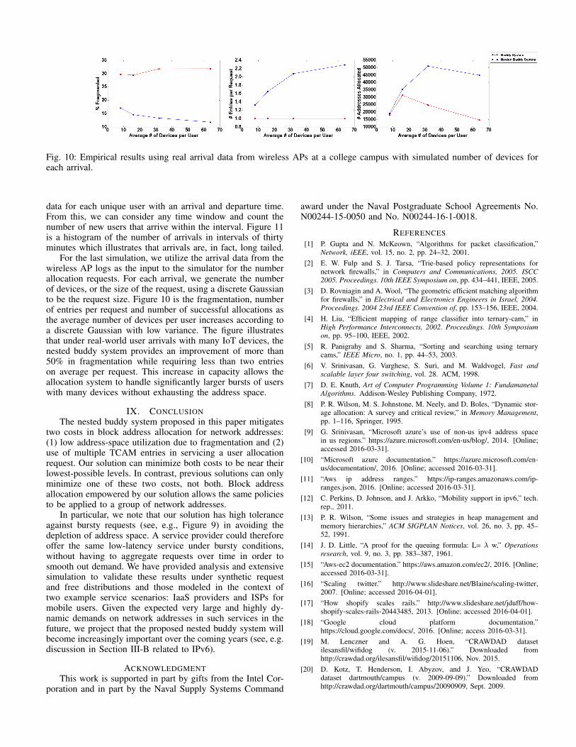
Fig. 10: Empirical results using real arrival data from wireless APs at a college campus with simulated number of devices foreach arrival.
data for each unique user with an arrival and departure time.From this, we can consider any time window and count thenumber of new users that arrive within the interval. Figure 11is a histogram of the number of arrivals in intervals of thirtyminutes which illustrates that arrivals are, in fact, long tailed.
For the last simulation, we utilize the arrival data from thewireless AP logs as the input to the simulator for the numberallocation requests. For each arrival, we generate the numberof devices, or the size of the request, using a discrete Gaussianto be the request size. Figure 10 is the fragmentation, numberof entries per request and number of successful allocations asthe average number of devices per user increases according toa discrete Gaussian with low variance. The figure illustratesthat under real-world user arrivals with many IoT devices, thenested buddy system provides an improvement of more than50% in fragmentation while requiring less than two entrieson average per request. This increase in capacity allows theallocation system to handle significantly larger bursts of userswith many devices without exhausting the address space.
IX. CONCLUSIONThe nested buddy system proposed in this paper mitigates
two costs in block address allocation for network addresses:(1) low address-space utilization due to fragmentation and (2)use of multiple TCAM entries in servicing a user allocationrequest. Our solution can minimize both costs to be near theirlowest-possible levels. In contrast, previous solutions can onlyminimize one of these two costs, not both. Block addressallocation empowered by our solution allows the same policiesto be applied to a group of network addresses.
In particular, we note that our solution has high toleranceagainst bursty requests (see, e.g., Figure 9) in avoiding thedepletion of address space. A service provider could thereforeoffer the same low-latency service under bursty conditions,without having to aggregate requests over time in order tosmooth out demand. We have provided analysis and extensivesimulation to validate these results under synthetic requestand free distributions and those modeled in the context oftwo example service scenarios: IaaS providers and ISPs formobile users. Given the expected very large and highly dy-namic demands on network addresses in such services in thefuture, we project that the proposed nested buddy system willbecome increasingly important over the coming years (see, e.g.discussion in Section III-B related to IPv6).
ACKNOWLEDGMENTThis work is supported in part by gifts from the Intel Cor-
poration and in part by the Naval Supply Systems Command
award under the Naval Postgraduate School Agreements No.N00244-15-0050 and No. N00244-16-1-0018.
REFERENCES[1] P. Gupta and N. McKeown, “Algorithms for packet classification,”
Network, iEEE, vol. 15, no. 2, pp. 24–32, 2001.[2] E. W. Fulp and S. J. Tarsa, “Trie-based policy representations for
network firewalls,” in Computers and Communications, 2005. ISCC2005. Proceedings. 10th IEEE Symposium on, pp. 434–441, IEEE, 2005.
[3] D. Rovniagin and A. Wool, “The geometric efficient matching algorithmfor firewalls,” in Electrical and Electronics Engineers in Israel, 2004.Proceedings. 2004 23rd IEEE Convention of, pp. 153–156, IEEE, 2004.
[4] H. Liu, “Efficient mapping of range classifier into ternary-cam,” inHigh Performance Interconnects, 2002. Proceedings. 10th Symposiumon, pp. 95–100, IEEE, 2002.
[5] R. Panigrahy and S. Sharma, “Sorting and searching using ternarycams,” IEEE Micro, no. 1, pp. 44–53, 2003.
[6] V. Srinivasan, G. Varghese, S. Suri, and M. Waldvogel, Fast andscalable layer four switching, vol. 28. ACM, 1998.
[7] D. E. Knuth, Art of Computer Programming Volume 1: FundamanetalAlgorithms. Addison-Wesley Publishing Company, 1972.
[8] P. R. Wilson, M. S. Johnstone, M. Neely, and D. Boles, “Dynamic stor-age allocation: A survey and critical review,” in Memory Management,pp. 1–116, Springer, 1995.
[9] G. Srinivasan, “Microsoft azure’s use of non-us ipv4 address spacein us regions.” https://azure.microsoft.com/en-us/blog/, 2014. [Online;accessed 2016-03-31].
[10] “Microsoft azure documentation.” https://azure.microsoft.com/en-us/documentation/, 2016. [Online; accessed 2016-03-31].
[11] “Aws ip address ranges.” https://ip-ranges.amazonaws.com/ip-ranges.json, 2016. [Online; accessed 2016-03-31].
[12] C. Perkins, D. Johnson, and J. Arkko, “Mobility support in ipv6,” tech.rep., 2011.
[13] P. R. Wilson, “Some issues and strategies in heap management andmemory hierarchies,” ACM SIGPLAN Notices, vol. 26, no. 3, pp. 45–52, 1991.
[14] J. D. Little, “A proof for the queuing formula: L= � w,” Operationsresearch, vol. 9, no. 3, pp. 383–387, 1961.
[15] “Aws-ec2 documentation.” https://aws.amazon.com/ec2/, 2016. [Online;accessed 2016-03-31].
[16] “Scaling twitter.” http://www.slideshare.net/Blaine/scaling-twitter,2007. [Online; accessed 2016-04-01].
[17] “How shopify scales rails.” http://www.slideshare.net/jduff/how-shopify-scales-rails-20443485, 2013. [Online; accessed 2016-04-01].
[18] “Google cloud platform documentation.”https://cloud.google.com/docs/, 2016. [Online; access 2016-03-31].
[19] M. Lenczner and A. G. Hoen, “CRAWDAD datasetilesansfil/wifidog (v. 2015-11-06).” Downloaded fromhttp://crawdad.org/ilesansfil/wifidog/20151106, Nov. 2015.
[20] D. Kotz, T. Henderson, I. Abyzov, and J. Yeo, “CRAWDADdataset dartmouth/campus (v. 2009-09-09).” Downloaded fromhttp://crawdad.org/dartmouth/campus/20090909, Sept. 2009.


![[IEEE CloudCom 2013] ClouDedup - Secure Deduplication with Encrypted Data](https://img.pdfslide.us/doc/110x75/54b87c424a7959c1078b4572/ieee-cloudcom-2013-cloudedup-secure-deduplication-with-encrypted-data.jpg)