Embed Size (px)
Citation preview

NEPAL ELECTRICITY AUTHORITY (An Undertaking of Government of Nepal)
PROJECT MANAGEMENT DIRECTORATE
SASEC Power System Expansion Project
MARSYANGDI-KATHMANDU 220kV T/L PROJECT
BIDDING DOCUMENT
FOR
Procurement of Plant for Marsyangdi-Kathmandu 220 kV Transmission Line
(Design, Supply and Install)
Single-Stage, Two-Envelope
Bidding Procedure
Issued on: ………………….
Invitation for Bids No.: ICB-PMD-MKTLP–072/73 - 02
ICB No.: ICB-PMD-MKTLP–072/73 - 02
Employer: Nepal Electricity Authority
Country: Nepal
VOLUME –II OF III
Section 1 to 7
February 2016
Marsyangdi-Kathmandu 220kV Transmission Line Project
Project Management Directorate
Matatirtha Substation, Chandragiri Municipality, Kathmandu, Nepal
Telephone: +977-1-5164143 Fax: +977-1-5164143

VOLUME –II
TECHNICAL SPECIFICATIONS
FOR TRANSMISSION LINE
CONTENTS
Section-1 : General Information and Scope
Section-2 : General Technical Conditions
Section-3 : Detailed Survey
Section-4 : Tower Foundation, Erection,
Stringing & Commissioning
Section-4A : Field Quality Plan
Section-5 : Conductor Specifications
Section-6 : Earthwire Specifications
Section-7A & 7B : Insulator Specifications
Section-8 : Hardware Fittings and Conductor
& Earthwire Accessories
Section-9 : OPGW Specifications
Section-10 : Drawings
Section-11 : Survey Report

Marsyangdi - Kathmandu 220 kV Transmission Line Project Supply and Installation
SECTION-I
Volume-II Doc. No : CC-Consultancy-NEA-M-K-2015
1
TECHNICAL SPECIFICATIONS
SECTION-I
GENERAL INFORMATION AND SCOPE
1. General Information and Scope
The primary objective of Nepal Electricity Authority (NEA) is to generate,
transmit and distribute adequate, reliable and affordable power by planning,
constructing, operating and maintaining all generation, transmission and
distribution facilities in Nepal's power system both interconnected and isolated.
NEA is the Executive Agency SASEC Power System Expansion Project (SPEP). SPEP
includes construction of (1) the 220kVDana-Kushma-New Butawal, and 400kV
New Butawal -Bardaghart transmission lines, and associated substations; (2)
Manang-Khudi- Udipu- Marki Chowk-Bharatpur 220kV transmission line and
associated substations; (3) Marsyangdi (Marki Chowk)- Matatirtha (Kathmandu)
220kV transmission line, and associated substations; (4) Samundratar - Trishuli
3B hub 132kV transmission line and associated substation at Samundratar; (5)
Grid substations reinforcement; (6) distribution systems in East, Central and
West regions.
1.1 Scope
1.1.1 The following transmission line is included in the scope of the Contractor:
220 kV D/C Marsyangdi - Kathmandu transmission line – approx. 81.6 kms
1.1.2 This Specification covers the following scope of works:
(i) Detailed survey including route alignment, profiling (where ever route change is required), tower spotting, optimization of tower locations, soil resistivity measurement & geotechnical investigation (including special foundation locations viz. pile/well foundation locations, whenever applicable & covered under BPS);
(ii) Check survey;
(iii) Design, Proto type testing, fabrication and supply of all type of 220kV double circuit transmission line towers including bolts, nuts and washers, step bolts, hangers, D-shackles etc.;
(iv) Supply of all types of tower accessories like phase plate, circuit plate (where ever applicable), number plate, danger plate, anti climbing device, Bird guard (where ever applicable);

Marsyangdi - Kathmandu 220 kV Transmission Line Project Supply and Installation
SECTION-I
Volume-II Doc. No : CC-Consultancy-NEA-M-K-2015
2
(v) Supply of Conductor, Insulators, Earth wire, Hardware Fittings, Accessories for Conductor & Earth wire and OPGW & associated fittings & accessories;
(vi) Design of foundations for different soil conditions for different type of towers, classification of foundation for different type of towers and casting of foundation for tower footings as per approved drawings;
(vii) Supply & Installation of Tower Earthing;
(viii) Erection of towers, tack welding of bolts and nuts including supply and application of zinc rich paint, fixing of insulator strings, stringing of conductors and earth wires/OPGW along with all necessary line accessories;
(ix) Painting of towers & supply and erection of span markers, obstruction lights (wherever applicable) for aviation requirements (as required)
(xi) Testing and commissioning of the erected transmission lines
(xii) Supply & Installation of PLS-CADD "Standard Edition along with Optimum spotting option" and PLS-Tower "Analysis, design and optimization of steel lattice towers" Softwares (10 multi-user licenses each) along with associated training (The Contractor shall include in the training charges (i) Accommodation charges (ii) payment of per Diem allowance to NEA trainees @ USD 150 per day per trainee for the duration of training abroad towards meals and other incidental expenses and (iii) to and fro economy class air ticket from Nepal to the place of training abroad) and
(xiii) Other items not specifically mentioned in this Specification and/or BPS but are required for the successful commissioning of the transmission line, unless specifically excluded in the Specification.
1.1.2.1 Contractor shall develop design, structural drawings, shop drawings & Bill of Materials of all 220 kV Double circuit towers and carryout the proto testing of towers. Similarly, the design and drawings for all type of foundations for the towers shall also be developed by the contractor, in sequence, suiting the project requirement.
1.1.2.2 (a) The provisional quantities of fabricated & galvanised steel towers as per specifications requirement, foundation type and their numbers, quantity of various line materials and other items are given in appropriate Price Schedule in Volume-III of the bid documents. However, the work shall be executed as per approved construction drawings and project requirement.
(b) The various item of work is described very briefly in the appropriate Price Schedule. The various items of the Price Schedule shall be read in conjunction with the corresponding sections in the Technical Specifications
Marsyangdi - Kathmandu 220 kV Transmission Line Project Supply and Installation
SECTION-I
Volume-II Doc. No : CC-Consultancy-NEA-M-K-2015
3
including amendments and, additions, if any. The Bidder’s rates shall be based on the description of activities in the Price Schedule as well as necessary operations detailed in these Technical Specifications.
(c) The Unit rates quoted shall include minor details which are obviously and fairly intended, and which may not have been included in these documents but are essential for the satisfactory completion of the various works.
(d) The unit rate quoted shall be inclusive of all plant equipment, men, material skilled and unskilled labour etc. essential for satisfactory completion of various works.
(e) All measurements for payment shall be in S.I. units, lengths shall be measured in meters corrected to two decimal places. Areas shall be computed in square meters & volume in cubic meters rounded off to two decimals.
1.1.3 All the raw materials such as steel, zinc for galvanising, reinforcement steel and cement for tower foundation, coke and salt for tower earthing etc., bolts, nuts, washers, D-shackles, hangers, links, danger plates, phase plates, number plates. Circuit Plates, anti climbing device, bird guards, etc., required for tower manufacture and erection shall be included in the Contractor’s scope of supply. Bidder shall clearly indicate in the offer, the sources from where they propose to procure the raw materials and the components.
1.1.4 The entire stringing work of conductor and earth wire/OPGW shall be carried out by tension stringing technique. The contractor shall indicate in their offer, the sets of tension stringing equipment he is having in his possession and the sets of stringing equipment he would deploy exclusively for this project. The period of deployment of tension stringing equipment shall be as per actual site requirement.
Power line crossing, river crossings, railway crossings, other single span sections where deployment of tension stringing machine is not warranted and in hilly terrain, thick forest or areas with site constraints, where deployment of tension stringing machine is not feasible , manual stringing may be adopted after getting approval of Employer’s site engineer. The contractor shall deploy appropriate tools / equipments / machinery to ensure that the stringing operation is carried out without causing damage to conductor/earth wire/OPGW which are installed at the prescribed sag-tension as per the approved stringing charts.
However, the Bidder having requisite experience has freedom to use helicopter for stringing. The Bidder intending to use helicopter shall furnish detailed description of the procedure, type & number of helicopter & accessories etc., to be deployed for stringing operation.

Marsyangdi - Kathmandu 220 kV Transmission Line Project Supply and Installation
SECTION-I
Volume-II Doc. No : CC-Consultancy-NEA-M-K-2015
4
The payment for stringing shall be done as per the unit rates of stringing under the contract irrespective of the methodology adopted for stringing.
1.1.5 The Bidder shall quote the unit rates for tower and foundation as per units mentioned in appropriate price schedules. However, payment of these items identified in the schedule of prices shall be made as follows:
Tower Supply : On completion of respective complete tower
Tower Erection : On erection of respective complete tower
Tower Foundation : On completion of respective foundation in all respect
1.1.6 This specification also includes the supply of Conductor, Insulators, Earthwire, hardware fittings, all type of accessories for conductor and earth wire and OPGW and its associated hardware & accessories as detailed in the specification. Contractor shall clearly indicate in their offer, the sources from where they propose to procure these materials in appropriate Schedule of BPS. The technical description of these items are given in relevant section of this Volume of the bidding documents.
1.1.7 Location Details and Terminal Points
The 220 kV (twin bundle) transmission line shall emanate from Marki Chowk sub-station in Abu Khaireni VDC of Tanahun district at the right bank of Marsyandi River and shall terminate at a tapping point near Matatirtha sub-station at Badbhanjyang VDC of Kathmandu district in Nepal. The transmission line shall be passing mainly through undulated hilly areas, cultivated land, barren land and forest stretches.
The Contractor shall have to construct the above 220 kV transmission line completely up to dead end towers on either end. Stringing shall also be carried out from dead end tower to terminal arrangements/terminal points.
1.2 Details of Transmission Line Routes and Terrain
Detailed survey including route alignment and profiling have been carried out by the Owner and these are not expected to vary substantially. The contractor has to carryout the tower spotting, optimization of tower locations, soil resistivity measurement & geotechnical investigation etc.
However, certain quantity of detailed survey including route alignment, profiling, tower spotting, optimization of tower locations soil resistivity measurement & geotechnical investigation etc. have been kept in the scope of the contractor for changes in the route, if any, necessitated during execution stage.

Marsyangdi - Kathmandu 220 kV Transmission Line Project Supply and Installation
SECTION-I
Volume-II Doc. No : CC-Consultancy-NEA-M-K-2015
5
The details collected through detailed survey viz, route alignment maps, detailed survey reports etc. are enclosed with this specification. Bidders may visit the line route to acquaint themselves with terrain conditions and associated details of the proposed transmission lines.
1.3 Access to the Line and Right of Way
Right of way and way leave clearance shall be arranged by the Owner in accordance with work schedules. Owner will secure way leave and Right of way in the Forest area. The responsibility of the Owner shall be limited to securing the Right of Way, compensation of land acquisition and permanent structure. All other responsibilities shall be of the Contractor as mentioned in Section 3. However, the details of the RoW shall be prepared by the Contractor as mentioned in Section 3.
1.4 Contractor Execution Plan
After award of the contract, the contractor shall submit a detailed plan for resources mobilization & execution of various activities under the project scope along with the L2 network to be approved by owner. The detail should also cover the locations and size of stores to be established by the contractor. The contractor shall be required to open at least three offices with stores.
The contractor shall deploy a Project Manager at site who shall not be allowed to be changed without the consent from NEA, once deployed. The work at site shall be carried out after permission from the Site-in-charge and with proper consent of land owners and forest officials.
2.0 Line Data:
2.1 Electrical System Data:
1. Nominal Voltage kV 220
2. Maximum system voltage kV 245
3. BIL (Impulse) kV (Peak) 1250
4. Power frequency withstand voltage (Wet)
kV (rms) 460
5. Minimum Corona extinction voltage at 50 Hz AC system under dry condition
kV (rms) phase to earth.
154 (Min)
6. Radio interference voltage at one MHz for phase to earth voltage of 154 KV
Micro Volts 1000 (Max)
Marsyangdi - Kathmandu 220 kV Transmission Line Project Supply and Installation
SECTION-I
Volume-II Doc. No : CC-Consultancy-NEA-M-K-2015
6
under dry condition.
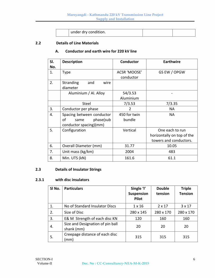
2.2 Details of Line Materials
A. Conductor and earth wire for 220 kV line
Sl. No.
Description Conductor Earthwire
1. Type ACSR ‘MOOSE’ conductor
GS EW / OPGW
2. Stranding and wire diameter
Aluminium / Al. Alloy 54/3.53 Aluminium
-
Steel 7/3.53 7/3.35
3. Conductor per phase 2 NA
4. Spacing between conductor of same phase(sub conductor spacing)(mm)
450 for twin bundle
NA
5. Configuration Vertical One each to run horizontally on top of the towers and conductors.
6. Overall Diameter (mm) 31.77 10.05
7. Unit mass (kg/km) 2004 483
8. Min. UTS (kN) 161.6 61.1
2.3 Details of Insulator Strings 2.3.1 with disc insulators
Sl No. Particulars Single ‘I’ Suspension
Pilot
Double tension
Triple Tension
1. No of Standard Insulator Discs 1 x 16 2 x 17 3 x 17
2. Size of Disc 280 x 145 280 x 170 280 x 170
3. E& M Strength of each disc KN 120 160 160
4. Size and Designation of pin ball shank (mm)
20 20 20
5. Creepage distance of each disc (mm)
315 315 315

Marsyangdi - Kathmandu 220 kV Transmission Line Project Supply and Installation
SECTION-I
Volume-II Doc. No : CC-Consultancy-NEA-M-K-2015
7
2.3.1 with composite long rod insulators
Sl No. Particulars Single ‘I’ Suspension
Pilot
Double tension
Triple Tension
1. No of Standard Insulator units 1 x 1 2 x 1 3 x 1
2. Size of Composite Insulator (Core dia x Nominal length) (mm)
24x2320
24x2890
24x2890
3. E& M Strength of each unit (KN) 120 160 160
4. Size and Designation of pin ball shank (mm)
20 20 20
5. Creepage distance of each unit (mm)
5040 5355 5355
Note : Bidder may quote for any one of the above options of insulators.
2.4 Insulator String Hardware (As may be applicable)
a) Anchor Shackle
b) Chain Link
c) Ball Clevis
d) Arcing horn holding plate
e) Yoke plate
f) Socket clevis
g) Arcing horns
h) Corona control ring/grading ring.
i) Clevis Eye
j) Free center type/Armour grip suspension clamp for suspension strings.
k) Compression type dead end clamp.
l) Sag adjuster.
m) Balancing weight
2.5 Accessories for Conductor & Earth wire (As may be applicable)
a) Preformed Armour rods
b) Mid Span compression joint

Marsyangdi - Kathmandu 220 kV Transmission Line Project Supply and Installation
SECTION-I
Volume-II Doc. No : CC-Consultancy-NEA-M-K-2015
8
c) Repair Sleeves
d) Flexible copper bonds
e) Vibration dampers
f) Rigid Spacers
g) Suspension clamp for earth wire.
h) Tension clamp for earth wire.
3.0 Service Conditions:
Equipment/material to be supplied against this specification shall be suitable for satisfactory continuous operation under tropical conditions as specified below:
Maximum ambient temperature (Degree Celsius) : 45
Minimum ambient temperature (Degree Celsius) : 0
Relative humidity (% range) : 10-100
Wind zone (as per IS: 875) : 4
Maximum wind velocity (m/sec.) : 47 m/sec
Maximum altitude above mean sea level (Meters) : upto 2000 m
Isoceraunic level (days/years) : 60
Climate varies from moderately hot and humid tropical climate to cold climate.

Marsyangdi - Kathmandu 220 kV Transmission Line Project Supply and Installation
Section-II Volume – II
1
TECHNICAL SPECIFICATIONS
SECTION - II
GENERAL TECHNICAL CONDITIONS
1.1 General
The following provisions shall supplement all the detailed technical specifications and requirements brought out herein. The contractor’s proposal shall be based on the use of materials complying fully with the requirements specified herein.
1.2 Engineering Data
1.2.1 The furnishing of engineering data by the Contractor shall be in accordance with the Schedule as specified in the Bidding Document. The review of these data by the Employer will cover only general conformance of the data to the specifications and not a through review of all dimensions, quantities and details of the materials, or items indicated or the accuracy of the information submitted. This review by the Employer shall not be considered by the Contractor, as limiting any of his responsibilities and liabilities for mistakes and deviations from the requirements, specified under these specifications.
1.2.2 All engineering data submitted by the Contractor after review by the Employer shall form part of the contract document.
1.3 Drawings
In addition to those stipulated in clause regarding drawings in GCC/SCC, the following also shall apply in respect of Contractor Drawings.
1.3.1 All drawings submitted by the Contractor including those submitted at the time of Bid shall be with sufficient detail to indicate the type, size, arrangement, dimensions, material description, Bill of Materials, weight of each component break-up for packing and shipment, fixing arrangement required, the dimensions required for installation and any other information specifically requested in these specifications.
1.3.2 Each drawing submitted by the Contractor shall be clearly marked with the name of the Employer, the specification title, the specification number and the name of the Project. All titles, noting, markings and writings on the drawing shall be in English. All the dimensions should be to the scale and in S.I. units.
1.3.3 The drawings submitted by the Contractor shall be reviewed by the Employer as far as practicable within 28 days and shall be modified by the Contractor if any
Marsyangdi - Kathmandu 220 kV Transmission Line Project Supply and Installation
Section-II Volume – II
2
modifications and/or corrections are required by the Employer. The Contractor shall incorporate such modifications and/or corrections and submit the final drawings for approval. Any delays arising out of failure by the Contractor to rectify the drawings in good time shall not alter the contract completion date.
1.3.4 The drawings submitted for approval to the Employer shall be in quadruplicate. One print of such drawings shall be returned to the Contractor by the Employer marked “approved/approved with corrections”. The contractor shall there upon furnish the Employer additional prints as may be required along with one reproducible in original of the drawings after incorporating all corrections.
1.3.5 The work shall be performed by the Contractor strictly in accordance with these drawings and no deviation shall be permitted without the written approval of the Employer, if so required.
1.3.6 All manufacturing, fabrication and erection work under the scope of Contractor, prior to the approval of the drawings shall be at the Contractor’s risk. The contractor may incorporate any changes in the design, which are necessary to conform to the provisions and intent of the contract and such changes will again be subject to approval by the Employer.
1.3.7 The approval of the documents and drawings by the Employer shall mean that the Employer is satisfied that:
(a) The Contractor has completed the part of the Works covered by the subject document (i.e. confirmation of progress of work).
(b) The Works appear to comply with requirements of Specifications.
In no case the approval by the Employer of any document does imply compliance with technical requirements nor the absence of errors in such documents.
If errors are discovered any time during the validity of the contract, then the Contractor shall be responsible for consequences.
1.3.8 All drawings shall be prepared using AutoCAD software version 2000 or later only. Drawings, which are not compatible to AutoCAD software version 2000 or later, shall not be acceptable. After final approval all the drawings shall be submitted to the Employer in CDs.
A copy of each drawing reviewed will be returned to the Contractor as stipulated herein.
1.3.9 Copies of drawings returned to the Contractor will be in the form of a print with the Employer’s marking, or a print made from a microfilm of the marked up drawing.

Marsyangdi - Kathmandu 220 kV Transmission Line Project Supply and Installation
Section-II Volume – II
3
1.3.10 The following is the general list of the documents and drawings that are to be approved by the Employer.
a) Work Schedule (Master Network) Plan.
b) Detailed survey report and profile drawings showing ground clearance and tower locations (as applicable).
c) Tower schedule and foundation classification for individual tower locations (as applicable).
d) Tower structural drawing and bill of materials.
e) Soil Investigation report.
f) Foundation working drawings/excavation Plan.
g) Tower footing earthing drawing.
h) Stub and stub-setting template drawings.
i) Stringing procedure and stringing chart.
j) Tower accessories drawings like danger plate, name plate etc.
k) Quality plans for fabrication and site activities including Quality System.
l) Sub-vendors approval, etc.
m) Line material drawings.
n) Type test report for line materials.
1.3.11 All rights of the design/drawing for all types of towers and foundations shall be strictly reserved with the Employer only and any designs/drawings/data sheets submitted by the contractor from time to time shall become the property of the Employer. Under no circumstances, the Contractor shall be allowed to use/offer above designs/drawings/data sheets to any other authority without prior written permission of the Employer. Any deviation to above is not acceptable and may be a cause for rejection of the bid.
1.4 Design Improvements
1.4.1 The Employer or the Contractor may propose changes in the specification and if the parties agree upon any such changes and the cost implication, the specification shall be modified accordingly.
Marsyangdi - Kathmandu 220 kV Transmission Line Project Supply and Installation
Section-II Volume – II
4
1.5 Design Co-ordination
Wherever, the design is in the scope of Contractor, the Contractor shall be responsible for the selection and design of appropriate material/item to provide the best co-coordinated performance of the entire system. The basic design requirements are detailed out in this Specification.
The design of various components, sub-assemblies and assemblies shall be so done that it facilitates easy field assembly and maintenance.
1.6 Design Review Meeting
The contractor will be called upon to attend design review meetings with the Employer, and the consultants of the Employer during the period of Contract. The contractor shall attend such meetings at his own cost at the Corporate Office of the Employer or at mutually agreed venue as and when required. Such review meeting will be held generally four times in a year.
1.7 Quality Assurance, Inspection & Testing
1.7.1 Quality Assurance
To ensure that the supply and services under the scope of this Contract whether manufactured or performed within the Contractor’s works or at his Sub-Contractor’s premises or at site or at any other place of work are in accordance with the specifications. The Contractor shall adopt suitable quality assurance programme to control such activities at all points necessary. Such programme shall be broadly outlined by the Contractor and shall be finalised after discussions before the award of Contract. The detailed programme shall be submitted by the contractor after the award of contract and finally accepted by the Employer after discussion. A quality assurance programme of the Contractor shall generally cover but not limited to the following:
(a) His organisation structure for the management and implementation of the proposed quality assurance programme.
(b) Documentation control System.
(c) Qualification data for Contractor’s key personnel.
(d) The procedure for purchase of materials, parts components and selection of sub-Contractor’s services including vendor analysis, source inspection, incoming raw material inspection, verification of material purchases etc.
(e) System for shop manufacturing including process controls and fabrication and assembly controls.
(f) Control of non-conforming items and system for corrective action.

Marsyangdi - Kathmandu 220 kV Transmission Line Project Supply and Installation
Section-II Volume – II
5
(g) Control of calibration and testing of measuring and testing equipments.
(h) Inspection and test procedure for manufacture.
(i) System for indication and appraisal of inspection status.
(j) System for quality audits.
(k) System for authorising release of manufactured product to the Employer.
(l) System for maintenance of records.
(m) System for handling storage and delivery and
(n) A quality plan detailing out the specific quality control procedure adopted for controlling the quality characteristics relevant to critical and important items of supply.
The Quality plan shall be mutually discussed and approved by the Employer after incorporating necessary corrections by the Contractor as may be required.
1.7.1.1 Quality Assurance Documents
The Contractor shall be required to submit all the Quality Assurance Documents as stipulated in the Quality Plan at the time of Employer's inspection of equipment/material.
1.7.1.2 The Employer or his duly authorised representatives reserves the right to carry out Quality Audit and quality surveillance of the systems and procedures of the Contractor's/his vendor's Quality Management and Control Activities.
1.7.2 Employer's Supervision
1.7.2.1 To eliminate delays and avoid disputes and litigation to the Contract, all matters and questions shall be resolved in accordance with the provisions of this document.
1.7.2.2 The manufacturing of the product shall be carried out in accordance with the specifications. The scope of the duties of the Employer, pursuant to the contract, will include but not be limited to the following.
a) Interpretation of all the terms and conditions of these Documents and Specifications.
b) Review and interpretation of all the Contractor's drawings, engineering data etc.
c) Witness or authorise his representative to witness tests at the manufacturer's works or at site, or at any place where work is performed under the contract.

Marsyangdi - Kathmandu 220 kV Transmission Line Project Supply and Installation
Section-II Volume – II
6
d) Inspect, accept or reject any equipment, material and work under the Contract, in accordance with the Specifications.
e) Issue certificate of acceptance and/or progressive payment and final payment certificate.
f) Review and suggest modification and improvement in completion schedules from time to time, and
g) Supervise the Quality Assurance Programme implementation at all stages of the works.
1.7.3 Inspection & Inspection Certificate
1.7.3.1 The Employer, his duly authorized representative and/or outside inspection agency acting on behalf of the Employer shall have, at all reasonable times, access to the premises and /or works of the contractor and/or their sub-contractor(s)/sub-vendors and shall have the right, at all reasonable times, to inspect and examine the materials and workmanship of the product during its manufacture.
1.7.3.2 The Contractor shall give the Employer's Inspector fifteen (15) days (in case of domestic testing and thirty (30) days (in case of foreign testing), as the case may be, written notice of any material being ready for testing. In case of turnkey contract, the turnkey contractor shall give the notice for inspection and shall associate in the inspection with Employee’s inspector. All such inspections shall be to the Contractor's account except for the expenses of the Employer’s inspector. The Employer’s inspector, unless witnessing of the tests is virtually waived, will attend such tests within fifteen (15) days (in case of domestic testing) and thirty (30) days in (in case of foreign testing) of the date of which the equipment is notified as being ready for test/inspection or on a mutually agreed date, failing which the Contractor may proceed with the test which shall be deemed to have been made in the inspector's presence and he shall forthwith forward to the inspector duly certified copies of test reports / certificates in triplicate.
1.7.3.3 The Employer’s Inspector shall, within fifteen (15) days from the date of inspection, give notice in writing to the Contractor, of any objection to any drawings and all or any equipment and workmanship which in his opinion is not in accordance with the Contract. The Contractor shall give due consideration to such objections and shall make the modifications that may be necessary to meet the said objections.
1.7.3.4 When the factory tests have been completed at the Contractor’s or Sub-Contractor’s works, the Employer’s inspector shall issue a certificate to this

Marsyangdi - Kathmandu 220 kV Transmission Line Project Supply and Installation
Section-II Volume – II
7
effect within fifteen (15) days after completion of tests but if the tests are not witnessed by the Employer’s inspector, the certificate shall be issued within fifteen (15) days of receipt of the Contractor’s Test Certificate by the Employer’s Inspector. The completion of these tests or the issue of the certificate shall not bind the Employer to accept the equipment should it, on further tests after erection, be found not to comply with the Contract.
1.7.3.5 In all cases where the Contract provides for test whether at the premises or works of, the Contractor or of any Sub-Contractor, the Contractor except where otherwise specified shall provide free of charge such item as labour, materials, electricity, fuel, water, stores, apparatus and instruments as may be reasonably demanded by the Employer’s inspector or his authorised representative to carry out effectively such tests of the equipment in accordance with the Contract and shall give facilities to the Employer’s Inspector or to his authorised representative to accomplish testing.
1.7.3.6 The inspection by Employer and issue of Inspection Certificate thereon shall in no way limit the liabilities and responsibilities of the Contractor in respect of the agreed Quality Assurance Programme forming a part of the Contract.
1.7.3.7 a) The Contractor shall keep the Employer informed in advance about the time of starting and of the progress of manufacture and fabrication of various parts at various stages, so that arrangements could be made for inspection.
b) The acceptance of any part of items shall in no way relieve the Contractor of any part of his responsibility for meeting all the requirements of the Specifications.
1.7.3.8 The Employer or his representative shall have free access at all reasonable times to those parts of the Contractor’s works which are concerned with the fabrication of the Employer’s material for satisfying him that the fabrication is being done in accordance with the provisions of the Specifications.
1.7.3.9 Unless specified otherwise, inspection shall be made at the place of manufacture prior to dispatch and shall be concluded so as not to interfere unnecessarily with the operation of the work.
1.7.3.10 Should any member of the structure be found not to comply with the supplied design, it shall be liable to rejection. No member once rejected shall be resubmitted for inspection, except in cases where the Employer or his authorised representative considers that the defects can be rectified.
1.7.3.11 Defect which may appear during fabrication shall be made good with the consent of, and according to the procedure proposed by the Contractor and approved by the Employer.

Marsyangdi - Kathmandu 220 kV Transmission Line Project Supply and Installation
Section-II Volume – II
8
1.7.3.12 All gauges and templates necessary to satisfy the Employer shall be supplied by the contractor.
1.7.3.13 The specified grade and quality of steel shall be used by the Contractor. To ascertain the quality of steel used, the inspector may at his discretion get the material tested at an approved laboratory.
1.7.4 Tests and Standards
1.7.4.1 Tests
The type, acceptance and routine tests and tests during manufacture shall be carried-out on the material and shall mean as follows:
1.7.4.1.1 Type Tests shall mean those tests which are to be carried out to prove the process of manufacture and general conformity of the material to this Specification. These tests shall be carried out on samples prior to commencement of commercial production against the order. The Bidder shall indicate his schedule for carrying out these tests.
1.7.4.1.2 Acceptance Tests shall mean those tests which are to be carried out on samples taken from each lot offered for pre-dispatch inspection, for the purposes of acceptance of that lot.
1.7.4.1.3 Routine Tests shall mean those tests, which are to be carried out on the material to check requirements which are likely to vary during production.
1.7.4.1.4 Tests during manufacture shall mean those tests, which are to be carried out during the process of manufacture and end inspection by the Contractor to ensure the desired quality of the end product to be supplied by him.
1.7.4.1.5 The norms and procedure of sampling for these tests will be as per the Quality Assurance Programme to be mutually agreed to by the Contractor and the Employer.
1.7.4.1.6 The standards and norms to which these tests will be carried out are listed against them. Where a particular test is a specific requirement of this Specification, the norms and procedure of the test shall be as specified in Annexure-A or as mutually agreed to between the Contractor and the Employer in the Quality Assurance Programme.
1.7.4.1.7 For all type and acceptance tests, the acceptance values shall be the values specified in this Specification or guaranteed by the Bidder, as applicable.

Marsyangdi - Kathmandu 220 kV Transmission Line Project Supply and Installation
Section-II Volume – II
9
1.7.4.2 Standards
The Codes and/or standards referred to in the specifications shall govern, in all cases wherever such references are made. In case of a conflict between such codes and/or standards and the specifications, the latter shall govern. Such codes and/or standards, referred to shall mean the latest revisions, amendments/changes adopted and published by the relevant agencies unless otherwise specified.
1.7.4.2.1 Other internationally accepted standards which ensure equal or better performance than those specified in the specifications of plant, equipments and works shall also be accepted, subject to prior approval by the *Owner/*Employer.
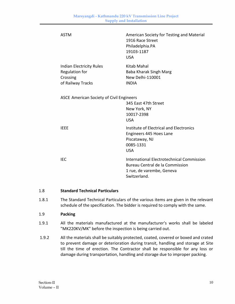
1.7.4.2.2 The standards are available from
Reference/Abbreviation Name and address from which the Standards/guides are available
IS Bureau of Indian Standards
Manak Bhawan, 9, Bahadur Shah Zafar Marg, New Delhi India.
ISO International Organisation for Standardisation, Danish Board for Standardisation, Dansk Standardising Sraat, Aurehoegvei-12 DK-2900 Hellepruip, DENMARK
CSA Canadian Standard Association 178,Rexadale Boulevard, Rexdale(Ontario) Canada M9W 1R3
DIN Deutsches Institute Fiir Normung Burggrafenstrassee 4-10 Post Fach 1107 D-1000, Berlin-30 GERMANY
Marsyangdi - Kathmandu 220 kV Transmission Line Project Supply and Installation
Section-II Volume – II
10
ASTM American Society for Testing and Material 1916 Race Street Philadelphia.PA 19103-1187 USA
Indian Electricity Rules Kitab Mahal Regulation for Baba Kharak Singh Marg Crossing New Delhi-110001 of Railway Tracks INDIA
ASCE American Society of Civil Engineers 345 East 47th Street New York, NY 10017-2398 USA
IEEE Institute of Electrical and Electronics Engineers 445 Hoes Lane Piscataway, NJ 0085-1331 USA
IEC International Electrotechnical Commission Bureau Central de la Commission 1 rue, de varembe, Geneva Switzerland.
1.8 Standard Technical Particulars
1.8.1 The Standard Technical Particulars of the various items are given in the relevant schedule of the specification. The bidder is required to comply with the same.
1.9 Packing
1.9.1 All the materials manufactured at the manufacturer's works shall be labeled "MK220KV/MK" before the inspection is being carried out.
1.9.2 All the materials shall be suitably protected, coated, covered or boxed and crated to prevent damage or deterioration during transit, handling and storage at Site till the time of erection. The Contractor shall be responsible for any loss or damage during transportation, handling and storage due to improper packing.

Marsyangdi - Kathmandu 220 kV Transmission Line Project Supply and Installation
Section-II Volume – II
11
1.9.3 The Contractor shall include and provide for securely protecting and packing the materials so as to avoid loss or damage during transport by air, sea, rail and road.
1.9.4 All packing shall allow for easy removal and checking at site. Wherever necessary, proper arrangement for attaching slings for lifting shall be provided. All packages shall be clearly marked for with signs showing ‘up’ and ‘down’ on the sides of boxes, and handling and unpacking instructions as considered necessary. Special precaution shall be taken to prevent rusting of steel and iron parts during transit by sea.
1.9.5 The cases containing easily damageable material shall be very carefully packed and marked with appropriate caution symbols, i.e. fragile, handle with care, use no hook etc. wherever applicable.
1.9.6 Each package shall be legibly marked by the Contractor at his expenses showing the details such as description and quantity of contents, the name of the consignee and address, the gross and net weights of the package, the name of the Contractor etc.
1.9.7 Angle section shall be wire bundled.
1.9.8 Cleat angles, gusset plates, brackets, fillet plate, hanger and similar loose pieces shall be tested and bolted together in multiples or securely wired through holes.
1.9.9 Bolts, nuts washers and other attachments shall be packed in double gunny bags accurately tagged in accordance with the contents.
1.9.10 The packing shall be properly done to avoid losses & damages during transit. Each bundle or package shall be appropriately marked.
1.10 Storage of Material
Brief guidelines for storage of different type of construction material used in the transmission line projects are as under:
1.10.1 Cement Storage
Cement received at site should be stored in a building or shed which is dry, leak proof and moisture proof. The building should have minimum numbers of windows. Cement bags stored and stacked off the floor on wooden planks in such a way so as to keep about 150 mm to 200 mm clearance from the ground. The floor may be of lean cement concrete or two layers of dry bricks laid on well consolidated earth. A minimum space of 600 mm shall be kept around and between the exterior walls and the stacks. In stacks, bags shall be kept close together to reduce air circulation. The height of the stack shall not be more than 12 bags and the width of the stack shall not be more than four bags or 3 meters. For extra safety during monsoon, or when it is expected to store for an unusually

Marsyangdi - Kathmandu 220 kV Transmission Line Project Supply and Installation
Section-II Volume – II
12
long period, the stack shall be completely enclosed by a waterproofing membrane such as polyethylene etc. Different type and make of cement shall be stacked and stored separately.
1.10.2 Aggregates
Aggregates shall be stored at site on a hard dry and level patch of ground. If such a surface is not available, a platform of planks or old corrugated iron sheets, or floor bricks or a thin layer of lean concrete shall be made so as to prevent contamination with clay, dust, vegetable and other foreign matter.
The stacks of fine and coarse aggregates shall be kept in separate stock piles sufficiently removed from each other to prevent the material at the edges of the piles from getting intermixed. Fine aggregate shall be stacked in a place where loss due to the effect of wind is minimum.
1.10.3 Reinforcement Steel
For each classification of steel, separate areas shall be earmarked. It is desirable that ends of bars and sections of each class be painted in distinct separate colors. Steel reinforcement shall be stored in such a way as to avoid distortion and to prevent deterioration and corrosion. It is desirable to coat reinforcement with cement wash before stacking to prevent scaling and rusting in case of storage time exceeding one month. In store, reinforcement bars shall be stacked above ground level by at least 150 mm either on brick/cement/stone platform or concrete/bricks planks.
1.10.4 Structural Steel or Tower Parts
The structural steer of different classification, sizes and lengths shall be stored separately. These shall be stored above ground level at least 150 mm upon platforms, skids or any other suitable supports to avoid any distortion of sections. Also, in order to prevent white rust formation sufficient care should be exercised while storing, handling and transporting galvanized products. The structural steel/tower parts shall be stored in an adequately ventilated area. The article shall be stored with spacers in between them and kept at an inclination to facilitate easy drainage of any water collected on the structural steel/tower parts.
1.10.5 Conductor & Earthwire Drums
It is essential to save the conductor drums from damage during storage and transportation and the wooden battens and main wheel should be intact so that same can be successfully mounted on the conductor jacks to release the conductor during stringing. All the conductor and earthwire drums should be stored on a proper hard platform above ground to avoid deterioration of the

Marsyangdi - Kathmandu 220 kV Transmission Line Project Supply and Installation
Section-II Volume – II
13
drum and further avoiding the damage of conductor. The conductor & earthwire drums should be stored in such a manner that each drum can be accessed at any time for inspection purposes.
1.10.6 Hardware fitting, Accessories & Insulators
All the hardware fittings, accessories and insulators should be stored on raised platform above ground so as not to damage the packaging and to avoid further damage or denting on the fittings and chipping of insulators. All the aluminum parts should be stored on a plain/raised platform under a cover shed in such a way that the aluminum fittings cannot be distorted during storage..
2.0 Environmental Mitigation Measures 2.1 Physical Environment The following mitigation measures shall be undertaken to reduce the adverse
impacts on the physical environment during construction of the transmission line.
1. Discharge of cement slurry, garbage and other solid wastes generated by the construction activities and workforce should be avoided where possible.
2. Chemical and other hazardous materials should be dumped safely far away from the water bodies.
3. Disposal material of substation should be carried out within the acquired land for substation. The waste materials of the substation shall be minimized to avoid separate land for disposal.
2.2 Biological Environment
None
2.3 Socio-economic and cultural Environment In the construction phase following mitigation measures shall be adopted in
accordance with the EIA final report to minimize the impacts:
Control of adverse socio interactions between local communities and construction work force.
Awareness program regarding health and safety of transmission line.
Awareness program for workforce.
Insurance against health and safety.
2.4 Employment

Marsyangdi - Kathmandu 220 kV Transmission Line Project Supply and Installation
Section-II Volume – II
14
The job preferences shall be given to local project affected family people.
Marsyangdi - Kathmandu 220 kV Transmission Line Project Supply and Installation
SECTION- III
VOLUME-II Doc. No : CC-Consultancy-NEA-M-K-2015
1
TECHNICAL SPECIFICATIONS
SECTION- 3
DETAILED SURVEY AND SOIL INVESTIGATION
1.0 Detailed Survey, Optimisation of Tower Location
1.1 Detailed survey along the route alignment has been carried out and profile has been plotted on the drawings by the Employer. Details of angle of deviation and section lengths along with route alignment drawings have been given in Section VIII/9 of Vol II. The Contractor shall have to do tower spotting on already prepared profile drawings, optimise tower locations and carry out the check survey for the total length of transmission line. Tower spotting, optimisation of tower locations and check survey shall have to be carried out by the Contractor in line with the provision stated in Clause 1.2 of Section – 1 of this Specification.
1.2 The Provisional quantity for detailed survey & check survey has been indicated in Price Schedule. The final quantity for the detailed survey shall be the route length along the revised route alignment, if any, and final quantity of check survey shall be the route length along the final route alignment. The tower spotting and optimization of tower locations shall be carried out by the Contractor on the basis of approved Tower Spotting Data preferably using PLS-CADD software.
1.3 The Contractor shall submit the proposal for detailed survey , in case of change (if necessary) in the present route alignment finalised by the Employer and shall carry out the detailed survey, profiling & optimization of tower locations only after getting approval from the Employer. The decision of Employer in this regard shall be final and binding for the Contractor. The Contractor shall finalise and submit results of detailed survey including changes suggested within the time schedule identified for completion of check survey and as agreed at the time of award. The soil investigation for the obligatory points are to be carried out by the Contractor as detailed out in this specification.
The Contractor should note that Employer will not furnish the topographical maps but will make available any assistance that may be required in obtaining the topographical maps.
1.4 The check survey shall be made along the approved route alignment after finalising the detailed survey.
1.5 Soil resistivity along the route alignment shall be measured in dry weather by four-electrode method keeping inter-electrode spacing of 50 meters. For calculating soil resistivity formula 2πar (where a=50 meters and r = megger reading in ohms) shall be adopted. Measurement shall be made at every 2 to 3 kms along the route of transmission lines. In case soil characteristic, changes

Marsyangdi - Kathmandu 220 kV Transmission Line Project Supply and Installation
SECTION- III
VOLUME-II Doc. No : CC-Consultancy-NEA-M-K-2015
2
within 2 to 3 kms., the value shall also have to be measured at intermediate locations. The megger reading and soil characteristics shall also be indicated in the soil resistivity results.
1.6 Detailed Survey
Following activities shall be part of Detailed Survey work:
1.6.1 Route Marking
At the starting point of the commencement of route marking for detailed survey an angle iron spike of 65x65x6mm section and 1000mm long shall be driven firmly into the ground to project only 150 mm above the ground level. A punch mark on the top section of the angle iron shall be made to indicate location of the survey instrument.
All angle positions and terminal points shall be marked with concrete pillars and all intermediate points should also be marked with concrete pillars a interval not more than 300 meters. The concrete pillars of minimum 100x100x600 mm in size with NEA marked on them shall be embedded into the ground for easy identification. The concrete pillars shall be embedded firmly into the ground to project 150 mm only above ground level.
1.6.2 Profile Plotting & Tower Spotting
From the field book entries, the route plan with route details and level profile shall be plotted and prepared to scale of 1:2000 horizontal & 1:400 vertical on the paper having grid of 10mmX10mm as per approved procedure. Reference levels at every 20 meters along the profile are also to be indicated on the profile besides, R/Ls at undulations. Areas along the profile sheet, in the view of the contractor, are not suitable for tower spotting, shall also be clearly marked on the profile plots. If the difference in levels be too high, the chart may be broken up accordingly to requirement. A 10mm overlap shall be shown on each following sheet. The chart shall progress from left to right having width of Sheet 594 mm wide. For ‘as built’ profile these shall be in A1 size.
1.7 Spotting of Tower Location
1.7.1 Sag Template & Tower Spotting Data
Sag - tension calculation for conductor & earth wire and other necessary data (ground clearance, permissible sag error etc. are provided with the bid. On basis of these, the Contractor shall prepare the Sag template curve drawing and Tower Spotting Data and shall submit the same along with sag –tension calculations for the approval of the Employer. Sag template prepared based on the approved sag-template curve drawing shall only be used for tower spotting on the profiles. Two numbers of the approved template, prepared on rigid transparent plastic

Marsyangdi - Kathmandu 220 kV Transmission Line Project Supply and Installation
SECTION- III
VOLUME-II Doc. No : CC-Consultancy-NEA-M-K-2015
3
sheet, shall be provided by the Contractor to the Employer for the purpose of checking the tower spotting. The templates shall be on the same scale as that of the profile.
1.7.2 Tower Spotting
With the help of approved sag template and tower spotting data, tower locations shall be marked on the profiles. While locating the towers on the profile sheet, the following shall be borne in mind:
(a) Span
The number of consecutive spans between the section points shall not exceed 15 spans or 5 Km in plain terrain and 10 spans or 3km in hilly terrain. A section point shall comprise of tension point with DB type or DC type or DD type towers as applicable.
(b) Extension
An individual span shall be as near to the normal design span as possible. In case an individual span becomes too short with normal supports on account of undulations in ground profile, one or both the supports of the span may be extended by inserting standard body and/or leg extension designed by the Contractor.
(c) Loading
There shall not be any upward force on suspension towers under normal working conditions and the suspension towers shall support at least the minimum weight span as provided in the designs. In case uplift is unavoidable, it shall be examined if the same can be overcome by adding standard body extensions to the towers failing which tension towers designed for the purpose shall be employed at such positions.
(d) Road Crossing
At all important road crossings, the tower shall be fitted with double suspension or tension insulator strings depending on the type of tower but the ground clearance at the roads under maximum conductor design temperature and in still air shall be such that even with conductor broken in adjacent span, ground clearance of the conductor from the road surfaces will not be less than 7.5m for 220KV lines. At all national highways suspension / tension towers shall be used and crossing span will not be more than 250 meters.
(e) River Crossings
In case of major river crossings towers shall be of suspension type and the anchor towers on either side of the main river crossing shall be DD type tower.
Marsyangdi - Kathmandu 220 kV Transmission Line Project Supply and Installation
SECTION- III
VOLUME-II Doc. No : CC-Consultancy-NEA-M-K-2015
4
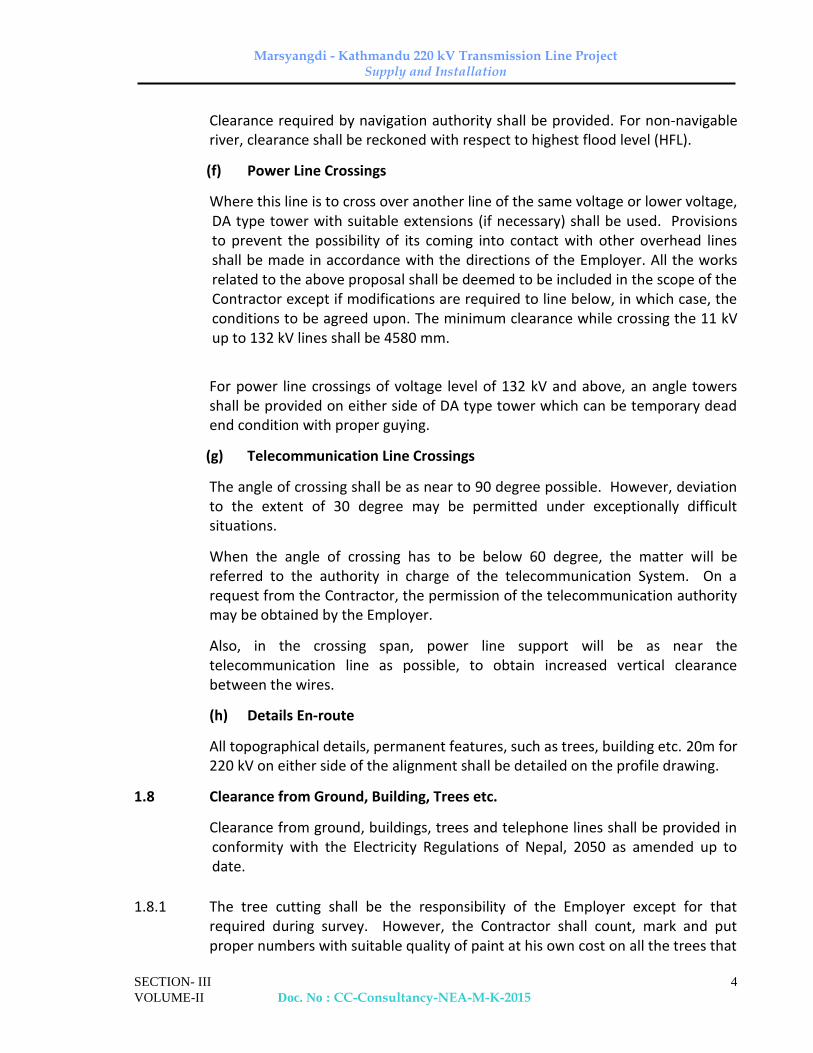
Clearance required by navigation authority shall be provided. For non-navigable river, clearance shall be reckoned with respect to highest flood level (HFL).
(f) Power Line Crossings
Where this line is to cross over another line of the same voltage or lower voltage, DA type tower with suitable extensions (if necessary) shall be used. Provisions to prevent the possibility of its coming into contact with other overhead lines shall be made in accordance with the directions of the Employer. All the works related to the above proposal shall be deemed to be included in the scope of the Contractor except if modifications are required to line below, in which case, the conditions to be agreed upon. The minimum clearance while crossing the 11 kV up to 132 kV lines shall be 4580 mm.
For power line crossings of voltage level of 132 kV and above, an angle towers
shall be provided on either side of DA type tower which can be temporary dead end condition with proper guying.
(g) Telecommunication Line Crossings
The angle of crossing shall be as near to 90 degree possible. However, deviation to the extent of 30 degree may be permitted under exceptionally difficult situations.
When the angle of crossing has to be below 60 degree, the matter will be referred to the authority in charge of the telecommunication System. On a request from the Contractor, the permission of the telecommunication authority may be obtained by the Employer.
Also, in the crossing span, power line support will be as near the telecommunication line as possible, to obtain increased vertical clearance between the wires.
(h) Details En-route
All topographical details, permanent features, such as trees, building etc. 20m for 220 kV on either side of the alignment shall be detailed on the profile drawing.
1.8 Clearance from Ground, Building, Trees etc.
Clearance from ground, buildings, trees and telephone lines shall be provided in conformity with the Electricity Regulations of Nepal, 2050 as amended up to date.
1.8.1 The tree cutting shall be the responsibility of the Employer except for that required during survey. However, the Contractor shall count, mark and put proper numbers with suitable quality of paint at his own cost on all the trees that

Marsyangdi - Kathmandu 220 kV Transmission Line Project Supply and Installation
SECTION- III
VOLUME-II Doc. No : CC-Consultancy-NEA-M-K-2015
5
are to be cut by the Employer at the time of actual execution of the work as detailed below. Contractor may please note that Employer shall not pay any compensation for any loss or damage to the properties or for tree cutting due to Contractor’s work.
1.8.2 Any way leave which may be required by the Contractor shall be arranged by the Employer as required by work programme.
1.8.3 To evaluate and tabulate the trees and bushes coming within 15m on either side
of the central line alignment the trees will be numbered and marked with quality paint serially from angle point AP (I) onwards (where I is tree no.) and the corresponding number will be painted on the stem of trees at a height of 1 meter from ground level. The trees list should contain the following:
a) Girth (circumference) measured at a height of 1 meter from ground level.
b) Approximate height of the tree with an accuracy of +2 meters.
c) Name of the type of the species/tree.
d) The bushy and under growth encountered in the 30M belt should also be evaluated with its type, height, girth and area in square meters, clearly indicating the growth in the tree/bush statement.
1.8.4 Payment of compensation towards the clearance etc. will be the responsibility of the Employer.
1.9 Preliminary Tower Schedule
The profile sheets, duly spotted, along with preliminary schedules indicating type of towers, type of foundations, wind span, weight span, angle of deviation, river / road crossing and other details shall be submitted for the approval of the Employer. After approval the Contractor shall submit four more sets of the approved reports along with one soft copy on CD of final profile drawings to the Employer for record purpose.
1.10 Check Survey for Tower Location
1.10.1 The check survey shall be conducted to locate and peg mark the tower positions on ground conforming to the approved profile and tower schedule. In the process, it is necessary to have the pit centers marked according to the excavation marking charts. The levels, up or down of each pit center with respect to the center of the tower location shall be noted and recorded for determining the amount of earthwork required to meet the approved design parameters &/or for determining the suitable leg extensions.
1.10.2 On tower locations having undulations, levels shall be taken at every 2 meter along the diagonals (connecting diagonal legs) of tower in area of 20 X 20 meters

Marsyangdi - Kathmandu 220 kV Transmission Line Project Supply and Installation
SECTION- III
VOLUME-II Doc. No : CC-Consultancy-NEA-M-K-2015
6
profile of the ground along the diagonal shall be plotted and submitted to the Employer.
1.10.3 Changes in the preliminary tower schedule after detailed / check survey, if required, shall be carried out by the Contractor and he shall thereafter submit a final tower schedule for the approval of Employer. The tower schedule shall show position of all towers, type of towers, span length, type of foundation for each towers and the deviation at all angles as set out with other details.
1.10.4 Identification of ROW and land parcel 1.10.4.1 The Scope of work of "Check Survey” also includes the identification of the land
parcel and permanent structures owned by public as well as private individuals on the Right of Way of Transmission Line (ROW is 15m on either side of the entire length of the Route Alignment) The Contractor shall mark the tower locations showing its boundary covering all four foundation pads and submit the details of affected Land Parcel numbers along with their areas for all tower locations to the Employer after the approval of check survey. The detail of which should include land plot number, and owners name and address as obtained from the records of Land revenue Office (Maalpot) and Survey Division (Naapi Sakha) of the concerned districts. It will be the responsibility of the Contractor to hire the Land Surveyors (Amin) and other required manpower, survey instruments & accessories, cadastal maps and collect the required information as mentioned herein above.
1.10.4.2 The Contractor is also required to identify the land parcel, and its owners along
with the detail of area of the land required for the foundation footing and submit the report to the Employer for the Purpose of permanent acquisition of land. The area of land required for permanent acquisition shall be based on the designed area of the foundation footing.
1.10.4.3 The Employer shall initiate the process for acquiring the ROW of Transmission
Line as well as permanent land acquisition for plot of land area required for foundation footing after verification of the Contractors report. However, if any error is identified in the information submitted by the contractor needing re-identification of land plot and its owner’s names, the Contractor shall immediately mobilize the crews to rectify error and resubmit the report at no extra cost.
1.10.4.4 The Employer, at the request of the Contractor shall request the various
Organizations or Offices of the Government of Nepal and local bodies to provide the necessary information to the Contractor. The Bidders are requested to familiarize themselves with the government rules & regulations and processes in the acquisition of land.

Marsyangdi - Kathmandu 220 kV Transmission Line Project Supply and Installation
SECTION- III
VOLUME-II Doc. No : CC-Consultancy-NEA-M-K-2015
7
1.10.4.5 All cost incurred in this connection shall be included in Check Survey work.
However, the compensation cost of land and permanent structures along the ROW and land costs for permanent acquisition of land for tower pads shall be borne by the Employer. Also, the cost of publication of notice and various meeting expenses that are likely to be incurred during price/compensation fixation shall be borne by the Employer.
1.10.4.6 Loss of standing crops: The Employer shall make compensation for the loss of
standing crops due to project activities. However the Contractor shall assess the quantity of such losses and forward the Employer with the necessary field measurements to substantiate timely compensation to the owners.
1.10.5 Right of Way (ROW) Clearance (Forest) 1.10.5.1 The Scope of work in “Right of Way (ROW) Clearance” includes the marking of
trees that are likely to be felled down to clear the ROW, taking detailed log of trees and its measurement with the help of forest technician as deputed by the District Forest Office of the concerned District, and submit the report to the Employer.
1.10.5.2 The Employer shall forward the report to the Forest Office and shall initiate the
process of getting approval for felling of trees. Upon approval on the report from the District Forest Office, contractor shall initiate the process of marking (which is termed as “TANCHA”) of the trees in coordination with the concerned District Forest Office.
1.10.5.3 After process of marking (TANCHA) of the trees by the Contractor, the Employer
shall clear the forest in the Right of Way. 1.10.5.4 The perdium allowance of forest technician/guards etc as deputed by
District/Community Forest Office during taking detailed log of the trees shall be paid by the Contractor as of actual man days involved in the works.
2.0 Environmental Conditions
2.1 Forest
The line route passing through forest stretches covered under this specification shall be furnished to the successful Bidder.
2.2 General Climatic Conditions

Marsyangdi - Kathmandu 220 kV Transmission Line Project Supply and Installation
SECTION- III
VOLUME-II Doc. No : CC-Consultancy-NEA-M-K-2015
8
Climatic conditions shall be as indicated at Cl.5.0 of Section–1 of this Specification.
2.3 Statutory Regulations and Standards
2.3.1 Statutory Regulations
The Contractor is required to follow local statutory regulations stipulated in Electricity Regulations of Nepal, 2050 as amended and other local rules and regulations referred in this Specifications.
2.3.2 Reference Standard
2.3.2.1 The Codes and/or standards referred to in the specifications shall govern, in all cases wherever such references are made. In case of a conflict between such codes and/or standards and the specifications, latter shall govern. Such codes and/or standards, referred to shall mean the latest revisions, amendments/changes adopted and published by the relevant agencies unless otherwise specified.
2.3.2.2 Other internationally accepted standards which ensure equal or better performance than those specified shall also be accepted, subject to prior approval by the Employer.
3.0 Geotechnical Investigations
3.1 General
3.1.1 Employer desires that a detailed Geotechnical investigation be carried out at various tower locations to provide the designer with sufficiently accurate information, both general and specific, about the substrata profile and relevant soil and rock parameters at site on the basis of which the foundation of transmission line towers can be classified and selected/designed rationally. The entire soil investigation work at river crossing locations (if required) shall be carried out by the Contractor. The range of load intensities from the various structures is expected to be between 100 KN/sq. m and 500 KN/sq.m.
3.1.2 These specifications provide general guidelines for geotechnical investigation of normal locations, including marshy locations and those affected by salt water or saltpeter. Any other specific information required for design of foundation suitable for such locations shall be obtained by the Contractor and furnished to the Employer.
3.2 Scope
3.2.1 The scope of work includes detail soil investigations and furnishing bore log data at various tower locations. The provisional quantities have been indicated in Bill of Quantities considering detail soil investigation at selected tension tower

Marsyangdi - Kathmandu 220 kV Transmission Line Project Supply and Installation
SECTION- III
VOLUME-II Doc. No : CC-Consultancy-NEA-M-K-2015
9
locations. However, during actual execution of work, the quantities shall be decided by the Engineer - in - Charge, depending upon the soil strata and terrain. Based on the bore log data / soil parameter / soil investigation results, the Contractor shall recommend the type of foundations suitable for each locations and the same shall be got approved by the Employer. For other locations, trial pit of is to be done in every locations for foundation classification up to foundation depth and furnish bore log data including the depth of ground water table. No separate payment for trial pit shall be done. Based on the soil parameters, the Contractor has to recommend the type of foundation suitable for each locations and same shall be got approved by the Employer.
3.2.2 These specifications cover the technical requirements for a detailed Geotechnical investigation and preparation & submission of a detailed Geotechnical Report. The work shall include mobilization of all necessary tools and equipment, provision of necessary engineering supervision and technical personnel, skilled and unskilled labour, etc. as required for carrying out the entire field investigation as well as laboratory tests, analysis and interpretation of data collected and preparation of the Geotechnical Report. The Contractor shall also collect data regarding variation of subsoil water table along the proposed line route. The aforementioned work shall be supervised by a graduate in Civil Engineering having at least 5 years of site experience in geotechnical investigation work.
3.2.3 Contractor shall make its own arrangements to establish the co-ordinate system required to position boreholes, trial pits and other field test locations as per the drawings/sketches supplied by Employer. Contractor shall determine the reduced levels (R.L's) at these locations with respect to benchmarks used in the detailed survey. Two reference lines shall be established based on survey data/details. Contractor shall provide at site all required survey instruments to the satisfactions of the Employer so that the work can be carried out accurately according to specifications and drawings. Contractor shall arrange to collect the data regarding change of course of rivers, major natural streams and nalas, etc., encountered along the transmission line route from the best available sources and shall furnish complete hydrological details including maximum velocity, discharge, highest flood level (H.F.L) & scour depth etc. of the concerned rivers, major streams and nalas (canals).
3.2.4 The field and laboratory data shall be recorded on the proforma recommended in relevant Indian Standards. Contractor shall submit to Employer two copies of field bore logs (one copy each to Employer’s site and corporate office) and the entire field records (countersigned by the Employer) soon after the completion of each borehole /test.
3.2.5 Whenever Contractor is unable to extract undisturbed samples, it shall immediately inform the Employer. Payment for boring charges shall be subject to

Marsyangdi - Kathmandu 220 kV Transmission Line Project Supply and Installation
SECTION- III
VOLUME-II Doc. No : CC-Consultancy-NEA-M-K-2015
10
Employer being satisfied that adequate effort has been made to extract undisturbed samples. Special care shall be taken for locations where marshy soils are encountered and Contractor in such cases shall ensure that specified numbers of vane shear tests are performed and the results correlated with other soil parameters.
3.2.6 One copy of all field records and laboratory test results shall be sent to Employer on a weekly basis. Employer may observe, the laboratory testing & procedures.
3.2.7 The Contractor shall interact with the Purchaser to get acquainted with the different types of structures envisaged and in assessing the load intensities on the foundation for the various types of towers in order to enable him to make specific recommendation for the depth, founding strata, type of foundation and the allowable bearing pressure etc.
3.2.8 After reviewing Contractor's geotechnical investigation draft report, Purchaser may call the contractor & his geotechnical engineer for discussions to be held at Employer’s site office / corporate office and give comments on the report. The report shall be redrafted & finalised by the contractor based on the comments and get the same approved from Employer’s site office. All expenditure associated with the redrafting and finalising the report including traveling etc. shall be deemed to have been included in the rates quoted for the geotechnical investigations.
3.2.9 Contractor shall carry out all work expressed and implied in Clause 3.2 of this specifications in accordance with requirements of the specification and satisfaction of the Employer.
3.3. General Requirements
3.3.1 Wherever possible, Contractor shall research and review existing local knowledge, records of test pits, boreholes, etc., types of foundations adopted and the behavior of existing structures, particularly those similar to the present project.
3.3.2 Contractor shall make use of information gathered from nearby quarries, unlined wells excavation etc. Study of the general topography of the surrounding areas will often help in the delineation of different soil types.
3.3.3 Contractor shall gather data regarding the removal of overburden in the project area either by performing test excavations, or by observing soil erosion or land slides in order to estimate reconsolidation of the soil strata. Similarly, data regarding recent landfills shall be studied to determine the characteristics of such land fill as well as the original soil strata.

Marsyangdi - Kathmandu 220 kV Transmission Line Project Supply and Installation
SECTION- III
VOLUME-II Doc. No : CC-Consultancy-NEA-M-K-2015
11
3.3.4 The water level in neighboring streams and watercourses shall be noted. Contractor shall make inquiries and shall verify whether there are abandoned underground works e.g. worked out ballast pits, quarries, old brick fields, mines, mineral workings etc. The possibility of damage to the structure, sewers, conduits and drainage system by subsidence shall also be investigated.
3.3.5 It is essential that equipment and instruments be properly calibrated at the commencement of the work. If the Purchaser so desires, Contractor shall arrange for having the instruments tested at an approved laboratory at their own cost and shall submit the test reports to the Employer. If the Employer desires to witness such tests, Contractor shall arrange for the same.
3.4 Codes and Standards for Geotechnical Investigations
All standards, specifications and codes of practice referred to herein shall be the latest editions including all applicable official amendments and revisions. In case of conflict between the present specifications and those referred to herein, the former shall prevail. Internationally accepted standards, which ensure equal or better performance than those specified shall also be accepted.
3.4.1 All work shall be carried out in accordance with the following Indian Standards and Codes:
Indian Title International and Standards (IS) Internationally Recognize Standard/Code
IS: 1080-1990 Codes of Practice for Design and Construction of Simple Spread Foundations
IS: 1498-1992 Classification and identification of ASTM D 2487/ Soils for General Engineering ASTM D 2488 purposes.
IS: 1888- 1982 Method of load tests on soil
IS: 1892-1992 Code of Practice for Subsurface Investigation for Foundation
IS: 1904-1986 Code of Practice for Design and Construction of foundation in Soils: General Requirements.
IS: 2131-1992 Method of Standard Penetration ASTM D 1586 Soils

Marsyangdi - Kathmandu 220 kV Transmission Line Project Supply and Installation
SECTION- III
VOLUME-II Doc. No : CC-Consultancy-NEA-M-K-2015
12
IS: 2132-1992 Code of Practice for Thin Walled ASTM D 1587 Sampling of Soils
IS: 2720-1992 Method of Test for Soils (Relevant ASTM D 420 Parts)
IS: 2809-1991 Glossary of Terms and symbols ASTM D 653 Relating to Soil Engineering
IS: 2810- 1979 Glossary of terms and symbols related to soil dynamics IS: 2911-1980 Code of Practice for Design and
construction of pile Foundations (Relevant Parts).
IS: 3025 Methods of Sampling and Testing (Physical and Chemical) for water used in industry.
IS: 3043-1991 Code of Practice for Earthing.
IS: 4078-1990 Code of Practice for Indexing and Storage of Drill Cores.
IS: 4091-1987 Code of Practice for Design and Construction of Foundations for Transmission Line Towers and Poles.
IS: 4434-1992 Code of Practice for in-situ Vane ASTM D 2573/ Shear Test for Soils. ASTM D 4648
IS: 4453-1992 Code of Practice for Exploration by Pits, Trenches, Drifts and Shafts.
IS: 4464-1990 Code of Practice for Presentation of Drilling Information and core description in Foundation Investigation
IS: 4968- Method for Subsurface sound- (Part-II)-1992 ing for soils, dynamic method using cone and Bentonite slurry
IS: 5313-1989 Guide for Core Drilling observations.
Marsyangdi - Kathmandu 220 kV Transmission Line Project Supply and Installation
SECTION- III
VOLUME-II Doc. No : CC-Consultancy-NEA-M-K-2015
13
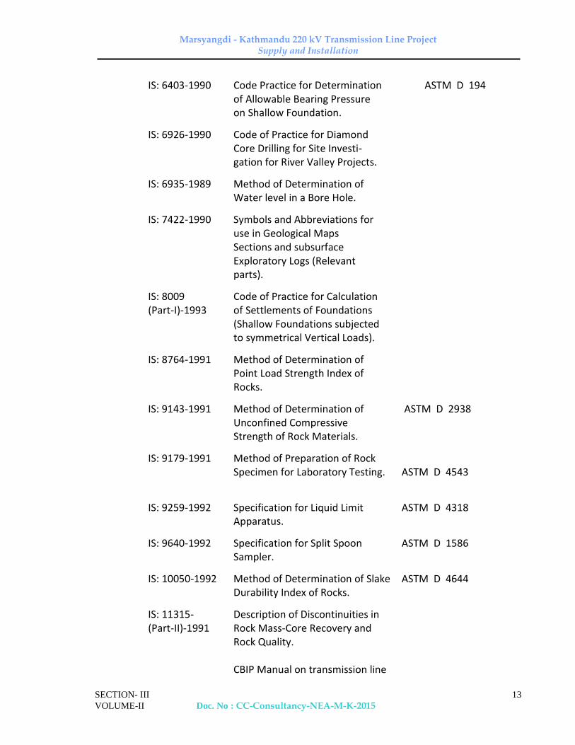
IS: 6403-1990 Code Practice for Determination ASTM D 194 of Allowable Bearing Pressure on Shallow Foundation.
IS: 6926-1990 Code of Practice for Diamond Core Drilling for Site Investi- gation for River Valley Projects.
IS: 6935-1989 Method of Determination of Water level in a Bore Hole.
IS: 7422-1990 Symbols and Abbreviations for use in Geological Maps Sections and subsurface Exploratory Logs (Relevant parts).
IS: 8009 Code of Practice for Calculation (Part-I)-1993 of Settlements of Foundations (Shallow Foundations subjected to symmetrical Vertical Loads).
IS: 8764-1991 Method of Determination of Point Load Strength Index of Rocks.
IS: 9143-1991 Method of Determination of ASTM D 2938 Unconfined Compressive
Strength of Rock Materials.
IS: 9179-1991 Method of Preparation of Rock Specimen for Laboratory Testing. ASTM D 4543
IS: 9259-1992 Specification for Liquid Limit ASTM D 4318 Apparatus.
IS: 9640-1992 Specification for Split Spoon ASTM D 1586 Sampler.
IS: 10050-1992 Method of Determination of Slake ASTM D 4644 Durability Index of Rocks.
IS: 11315- Description of Discontinuities in (Part-II)-1991 Rock Mass-Core Recovery and Rock Quality. CBIP Manual on transmission line

Marsyangdi - Kathmandu 220 kV Transmission Line Project Supply and Installation
SECTION- III
VOLUME-II Doc. No : CC-Consultancy-NEA-M-K-2015
14
towers, Chapter – 10 Foundations 3.5 Field Investigation for Soils
Tentative numbers of detailed soil investigation to be done is given in BPS.
3.5.1 Boring
Boreholes are required for detailed soil investigations.
3.5.1.1 General Requirements
a) Boreholes shall be made to obtain information about the subsoil profile, its nature and strength and to collect soil samples for strata identification and for conducting laboratory tests. The minimum diameter of the borehole shall be 150mm and boring shall be carried out in accordance with the provisions of IS: 1892 and this specification:
b) All boreholes shall be minimum 7m deep for normal open cast type foundations. If the strata with Standard Penetration Test–N value measured greater than 100 with characteristics of rock is met, the borehole shall be advanced by coring at least 3m further, limited to total 7m depth, with prior approval of the Purchaser.
c) Casing pipe shall be used when collapse of a borehole wall is probable. The bottom of the casing pipe shall at all times be above the test of sampling level but not more than 15cm above the borehole bottom. In case of cohesion less soils, the advancement of the casing pipe shall be such that it does not disturb the soil to be tested or sampled. The casing shall preferably be advanced by slowly rotating the casing pipe and not by driving.
d) In-situ tests shall be conducted and undisturbed samples shall be obtained in the boreholes at intervals specified hereafter. Representative disturbed samples shall be preserved for conducting various identification tests in the laboratory. Water table in the borehole shall be carefully recorded and reported following IS: 6935. No water or drilling mud shall be used while boring above ground water table. For cohesion less soil below water table, the water level in the borehole shall at all times be maintained slightly above the water table.
e) The borehole shall be cleaned using suitable tools to the depth of testing or sampling, ensuring least or minimum disturbance of the soil at the bottom of the borehole. The process of jetting through an open tube sampler shall not be permitted. In cohesive soils, the borehole may be cleaned by using a bailer with a flap valve. Gentle circulation of drilling fluid shall be done when rotary mud circulation boring is adopted.

Marsyangdi - Kathmandu 220 kV Transmission Line Project Supply and Installation
SECTION- III
VOLUME-II Doc. No : CC-Consultancy-NEA-M-K-2015
15
f) On completion of the drilling, Contractor shall backfill all boreholes as directed by the Purchaser.
3.5.1.2 Auger Boring
Auger boring may be employed in soft to stiff cohesive soils above the water table. Augers shall be of helical or post hole type and the cuttings brought up by the auger shall be carefully examined in the field and the description of all strata shall be duly recorded in the field bore log as per IS: 1498. No water shall be introduced from the top while conducting auger boring.
3.5.1.3 Shell and Auger Boring
3.5.1.3.1 Shell and auger boring may be used in all types of soil that are free from boulders. For cohesion less soil below ground water table, the water level in the borehole shall always be maintained at or above ground water level.
3.5.1.3.2 The use of chisel bits shall be permitted in hard strata having SPT-N value greater than 100. Chisel bits may also be used to extend the borehole through local obstructions such as old construction, boulders, rocky formations, etc. The requirements in Clause 3.5.1.2 shall apply for this type of boring also.
3.5.1.4 Rotary Boring
Rotary boring method may be used in all types of soil below water table. In this method the boring is carried out by rotating the bit fixed at the lower end of the drill rod. Proper care shall be taken to maintain firm contact between the bit and the bottom of the borehole. Bentonite or drilling mud shall be used as drilling fluid to stabilise and protect the inside surface of the borehole. Use of percussion tools shall be permitted in hard clays and in dense sandy deposits.
3.5.2 Standard Penetration Test (SPT)
3.5.2.1 This test shall be conducted in all types of soil deposits encountered within a borehole, to find the variation in the soil stratification by correlating with the number of blows required for unit penetration of a standard penetrometer. Structure sensitive engineering properties of cohesive soils and sifts such as strength and compressibility shall not be inferred based on SPT values. No extra payment shall be made for carrying out Standard Penetration Tests.
The test shall be conducted at depths as follows:
Location Depths (m)
Normal Soils 2.0, 3.0, 5.0, 7.0
3.5.2.2 The spacing between the levels of standard penetration testing and next undisturbed sampling shall not be less than 1.0m. The Equipments, other

Marsyangdi - Kathmandu 220 kV Transmission Line Project Supply and Installation
SECTION- III
VOLUME-II Doc. No : CC-Consultancy-NEA-M-K-2015
16
accessories, procedures for conducting the test and collection of the disturbed soil samples shall conform to IS: 2131 and IS: 9640. The rods shall be straight, tightly coupled and the air release valve shall be checked. The test shall be conducted immediately after reaching to the test depth and cleaning of bore hole.
3.5.2.3 The test shall be carried out by driving a standard split spoon sampler in the borehole by means of a 650N hammer falling freely from a height of 750mm for 450mm depth, recording the number of blows for every 75mm. The number of blow for the last 300mm drive shall be reported as measured N value.
3.5.2.4 This test shall be discontinued when blow count has reached 100 or the penetration is less than 25 mm for 50 blows, whichever is earlier, or sampler starts jumping. At the level where the test is discontinued, the number of blows and the corresponding penetration shall be reported. Sufficient quantity of disturbed soil samples shall be collected from the split spoon sampler for identification and laboratory testing. The sample shall be visually classified and recorded at the site as well as properly preserved without loss of moisture content and labeled.
3.5.3 Sampling
3.5.3.1 General
a) Sufficient number of soil samples shall be collected. Disturbed soil samples shall be collected for field identification and for conducting laboratory tests such as grain size (sieve) analysis, index properties, specific gravity, chemical analysis etc. Undisturbed samples shall be collected to estimate the physical, strength, swelling and consolidation properties of the soil.
b) All accessories and sampling methods shall conform to IS: 2132. All the representative disturbed and undisturbed samples collected in the field shall be classified at site as per IS: 1498. The specification for thin wall sampling tube and sampler heads should be as per IS: 11594.
c) All samples shall be identified with date, borehole or test pit number, date of sampling, etc. It is also essential to mark an arrow pointing towards the top surface of the undisturbed sample tube as the soil in-situ. Care shall be taken to keep the core and box samples vertically, with the arrow mark directing upwards. All undisturbed samples shall be properly trimmed at one end and suitably capped and sealed with molten paraffin wax on both sides. The Contractor shall be responsible for packing, storing in a cool place and transporting all the samples from site to the laboratory within seven days after sampling with proper protection against loss and damage.
3.5.3.2 Disturbed Samples

Marsyangdi - Kathmandu 220 kV Transmission Line Project Supply and Installation
SECTION- III
VOLUME-II Doc. No : CC-Consultancy-NEA-M-K-2015
17
a) Disturbed soil samples shall be collected in boreholes at regular intervals. Jar samples weighing approximately (10 N)1 Kg shall be collected at 0.5m intervals starting from a depth of 0.5m below ground level and at every identifiable change of strata to supplement the boring records and at the levels of Standard Penetration Tests (SPT), obtained in a SPT sampler shall also be collected. Samples shall be stored immediately in airtight jars, which shall be filled to capacity as much as possible.
b) In designated borrow areas, bulk samples, from a depth of about 0.5m below ground level shall be collected to establish the required properties for use as a fill material. Disturbed samples weighing about 25kg (250 N) shall be collected at shallow depths and immediately stored in polythene bags as per IS: 1892. The bags shall be sealed properly to preserve the natural moisture content of the sample and shall be kept in wooden boxes for transportation.
3.5.3.3 Undisturbed Samples
The undisturbed soil samples shall be collected immediately after drilling and cleaning the borehole upto the desired depth. Effort shall be made that the preparations are made before hand to collect the sample after reaching to the desired depth. In each borehole undisturbed samples shall be collected at every change of strata and at depths as follows:
Location Depths (m) Normal foundations 1.0, 4.0, 6.0
3.5.3.3.1 The depth interval between the top levels of undisturbed sampling and standard penetration testing shall not be less than 1.0m. Undisturbed samples shall be of 100mm diameter and 450mm in length. Samples shall be collected in a manner to preserve the structure, density and moisture content of the soil. Accessories required for sampling and sampling procedures shall conform to IS: 1892 and IS: 2132 and other related IS Codes. Undisturbed sampling in sand shall be done using compressed air technique mentioned in IS: 8763.
a) Undisturbed sampling in cohesive soil:
Undisturbed samples in soft to stiff cohesive soils shall be obtained using a thin walled sampler. In order to reduce the wall friction, suitable precautions, such as oiling the surfaces shall be taken. The sampling tube shall have a smooth finish on both surfaces and a minimum effective length of 450mm. The area ratio of sampling tubes shall be less than 12.5%. However, in case of very stiff soils area ratio up to 20% shall be permitted. Inside clearance ratio and outside clearance ratio shall be as specified by IS code.
Marsyangdi - Kathmandu 220 kV Transmission Line Project Supply and Installation
SECTION- III
VOLUME-II Doc. No : CC-Consultancy-NEA-M-K-2015
18
b) Undisturbed samples in very loose saturated sandy and silty soils and very soft clays shall be obtained by using a piston sampler consisting of a sampling cylinder and piston system. In soft clays and silty clays, with water standing in the casing pipe, piston sampler shall be used to collect undisturbed samplers in the presence of expert supervision.
Accurate measurements of the sampling depth, height of sampler, stroke and length of sample recovered shall be recorded. After the sampler is pushed to the required depth, the cylinder and piston system shall be drawn up together, ensuring that there shall not any disturbance to the sample.
c) Undisturbed sampling in cohesion less soil
Undisturbed samples in cohesion less soils shall be obtained as per the procedure given in IS: 8763. Compressed air Sampler shall be used to take sample of cohesion less soils below water table.
d) The sampler should be cleaned (not rusted), oiled and connected with straight drill rods coupled tightly. The air-released valve should be checked every time before lowering the sampler. At the time of lowering the sampler it should be ensured that bore hole is cleaned, casing is not below the depth of sampling and water level in the bore hole is above the water table preferably up to ground surface if sampling is done below water table.
e) The collected sample should be sealed on both ends of the sampler with wax. They should be given identification numbers and kept in the airtight wooden boxes. They should be transported in truck with a care that the structure of soil samples would not change due to vibration during transportation. They should be kept in a testing laboratory and should be tested within seven days or before.
3.5.4 Ground Water Table
3.5.4.1 One of the following methods shall be adopted for determining the elevation of ground water table in boreholes as per IS: 6935 and the instructions of the Purchaser:
a) In permeable soils, the water level in the borehole shall be allowed to stabilise after depressing it adequately by bailing before recording its level. Stability of sides and bottom of the boreholes shall be ensured at all times.
b) For both permeable and impermeable soils, the following method shall be suitable. The borehole shall be filled with water and then bailed out to various depths. Observations on the rise or fall of water level shall be made at each depth. The level at which neither fall nor rise is observed shall be considered the water table elevation and confirmed by three successive readings of water level taken at two hours interval.

Marsyangdi - Kathmandu 220 kV Transmission Line Project Supply and Installation
SECTION- III
VOLUME-II Doc. No : CC-Consultancy-NEA-M-K-2015
19
3.5.4.2 If any variation of the ground water level is observed in any specific boreholes, the water level in these boreholes shall be recorded daily during the course of the filed investigation. Levels in nearby wells, streams, etc., if any, shall also be noted in parallel. Care should be taken to ensure any abrupt change in water level in borehole is recorded.
3.5.4.3 Subsoil water samples
a) Subsoil water samples shall be collected for performing chemical analysis. Representative ground water samples shall be collected when first encountered in boreholes and before the addition of water to aid boring or drilling.
b) Chemical analysis of water samples shall include determination of pH value, turbidity, sulphate, carbonate, nitrate and chloride contents, presence of organic matter and suspended solids. Chemical preservatives may be added to the sample for cases as specified in the test methods or in applicable Indian Standards. This shall only be done if analysis cannot be conducted within an hour of collection and shall have the prior written permission and approval of the Purchaser.
3.5.5 Dynamic Cone Penetration Test (For marshy locations, with bentonite slurry)
Dynamic cone penetration test shall be conducted with bentonite slurry to predict stratification, density, bearing capacity of granular soils, etc. The test shall be conducted by driving a standard size cone attached to the bottom of a string of straight and tightly coupled drill rods to the specified depth or refusal, whichever comes first. Refusal shall be considered when the blow count exceeds 100 150 for 300mm penetration. The Equipment, accessories required for performing the test, test procedures, field observations and reporting of results shall conform to IS: 4968, Part-II. The driving system shall comprise of a 650 N weight having a free fall of 750mm. The cone shall be 600 and of 65mm diameter provided with vents for continuous flow of bentonite slurry through the cone and rods in order to avoid friction between the rods and soil. On completion of the test the results shall be presented as a continuous record of the number of blows required for every 300mm penetration of the cone into the soil in a suitable chart supplemented by a graphical plot of blow count for 300mm penetration vs. depth. On completion of the test, the results shall be presented on the format approved by the Purchaser.
3.5.6 Dynamic cone penetration test without slurry
The test shall be conducted for prediction of different soil strata, their relative strength or density or both. The 50mm diameter 600 cone shall be fitted loosely to the driving rod through a cone adopter. The cone shall be driven in to the soil by allowing the 650 N weight hammer to fall freely through a height of 750mm
Marsyangdi - Kathmandu 220 kV Transmission Line Project Supply and Installation
SECTION- III
VOLUME-II Doc. No : CC-Consultancy-NEA-M-K-2015
20
each time. The number of blows for every 75mm penetration shall be recorded. The process shall be repeated till the cone is driven to the required depth. The penetration depth shall be limited to 5m in cohesion less soil and 10m in mixed soil with some binding material. The cone driving rods, driving head, hoisting equipment shall conform to IS: 10589. The test and report should be prepared as per guidelines of IS: 4968 (Part I).
3.5.7 Vane Shear Test (required for boreholes where UDS is not possible in marshy locations)
Field vane shear test shall be performed inside the borehole to determine the shear strength of cohesive soils, especially of soft and sensitive clays, which are highly susceptible to sampling disturbance. This test shall be conducted by advancing a four-winged vane of suitable size (75mm or 100mm diameter as per the soil condition) into the soil at the desired depth and measuring the torque required to rotate the vane. The equipments and accessories required for conducting test, test procedures and field observations shall correspond to IS: 4432. Tests may also be conducted by direct penetration from ground surface. If the cuttings at the test depth in the borehole show any presence of gravel, sand, shells, decomposed wood, etc., which is likely to influence the test results substantially, the test at that particular depth may be omitted with the permission of the Purchaser. However, the test shall be conducted at a depth where these obstructions cease to occur. On completion of the test, the results shall be reported in an approved Performa as specified in IS: 4434, Appendix-A.
3.6 Field Investigation for Rock
3.6.1 Rock Drilling
3.6.1.1 If, during the investigations, large hard fragments or natural rock beds like but not limited to igneous, sedimentary and metamorphic formations are encountered, work shall proceed with core drilling methods. The equipment and procedures for this operation shall conform to IS: 1892. The starting depth of drilling in rock shall be certified by the Purchaser. At the end of the investigation, the hole drilled in rock shall be backfilled with grout consisting of 1 part cement and 3 parts sand by weight.
3.6.1.2 Drilling shall be carried out with NX size tungsten carbide (TC) or diamond tipped drill bits, depending on the type of rock and according to IS: 6929. Suitable type of drill bit (TC/Diamond) and core catchers shall be used to ensure continuous and good core recovery. Core barrels and core catchers shall be used for breaking off the core and retaining it when the rods are withdrawn. Double and triple tube core barrels shall be used to ensure better core recovery and to retrieve cores from layers of bedrock. Water shall be circulated continuously in

Marsyangdi - Kathmandu 220 kV Transmission Line Project Supply and Installation
SECTION- III
VOLUME-II Doc. No : CC-Consultancy-NEA-M-K-2015
21
the hollow rods and the sludge conveying the rock cuttings to the surface shall be collected. A very high core recovery ratio shall be aimed in order to obtain a satisfactory undisturbed sample. Attempt shall be made to recover cores of 1.5m in length. Normally TC bit shall be used. Change over to a diamond bit shall require the specific written approval of the Purchaser, and his decision as to whether a TC or a diamond bit is to be used shall be final and binding on Contractor.
3.6.1.3 No drilling run shall exceed 1.5m in length. If the core recovery is less than 80% in any run, the length of the subsequent run shall be reduced to 0.75m. During drilling operations observations on return water, loss of water, rate of penetration etc. shall be made and reported as per IS: 5313.
a) The colour of return water at regular intervals, the depth at which any change of colour of return water is observed, the depth of occurrence and amount of flow of hot water, if encountered, shall be recorded.
b) The depth through which a uniform rate of penetration was maintained, the depth at which marked change in rate of penetration or sudden fail on drill rod occurs, the depth at which any blockage of drill bit causing core loss, if any, shall be recorded.
c) Any heavy vibration or torque noticed during the drilling should be recorded together with the depth of occurrence.
c) Special conditions like the depth at which grouting was done during drilling, presence of artesian conditions, loss of drilling fluid,
d) observations of gas discharge with return water, etc., shall also be observed and recorded.
e) All the observations and other details shall be recorded as per daily drill and reported in a proforma as given in IS: 5313, Appendix A.
3.6.2 Core Sampling
3.6.2.1 Core samples shall be extracted by the application of a continuous pressure at one end of the core with the barrel held horizontally without vibration. Friable cores shall be extracted from the barrel directly into a suitably sized half round plastic channel section. Care shall be taken to maintain the direction of extrusion of sample same as while coring, to avoid stress reversal.
3.6.2.2 Immediately after withdrawal from the core barrel; the cores shall be placed in a tray and transferred to core boxes specially prepared for this purpose. The boxes shall be made from seasoned timber or any other durable material and shall be indexed on top of the lid according to IS: 4078. The cores shall be numbered serially and arranged in the boxes in a sequential order. The description of the

Marsyangdi - Kathmandu 220 kV Transmission Line Project Supply and Installation
SECTION- III
VOLUME-II Doc. No : CC-Consultancy-NEA-M-K-2015
22
core samples shall be recorded as instructed in IS: 4464. Where no core is recovered, it shall be recorded as specified in the standard. Continuous records of core recovery and rock quality designation (RQD) are to be mentioned in the bore log in accordance with IS: 11315 (Part-II). Color photograph of cores shall be taken. The core shall be put in sealed polythene bags. The core boxes should be transported carefully so that core should not be broken. They should be stored in dry place and should be sent for testing immediately.
3.7 Laboratory Testing
3.7.1 Essential Requirements
a) Depending on the types of substrata encountered, appropriate laboratory tests shall be conducted on soil and rock samples collected in the field. Laboratory tests shall be scheduled and performed by qualified and experienced personnel who are thoroughly conversant with the work. Tests indicated in the schedule of items shall be performed on soil, water and rock samples as per relevant IS codes. One copy of all laboratory test data records shall be submitted to Purchaser progressively every week. Laboratory tests shall be carried out concurrently with the field investigations, as initial laboratory test results could be useful in planning the later stages of fieldwork. A schedule of laboratory tests shall be established by Contractor to the satisfaction of the Purchaser within one week of completion of first borehole.
b) Laboratory tests shall be conducted using approved apparatus complying
with the requirements and specification of Indian Standards or other approved standards for this type of work. It shall be checked that the apparatus are in good working condition before starting the laboratory tests. Calibration of all the instruments and their accessories shall be done carefully and precisely at an approved laboratory.
c) All samples, whether undisturbed or disturbed shall be extracted, prepared and examined by competent personnel properly trained and experienced in soil sampling, examination, testing and in using the apparatus in conformance with the specified standards.
d) Undisturbed soil samples retained in liners or seamless tube samplers shall
be removed, without causing any disturbance to the samples, using suitably designed extruders just prior to actual testing. If the extruder is horizontal, proper support shall be provided to prevent the sample from breaking. For screw tube extruders, the pushing head shall be free from the screw shaft so that no torque is applied to the soil sample in contact with the pushing head. For soft clay samples, the sample tube shall be cut by means of a high-speed

Marsyangdi - Kathmandu 220 kV Transmission Line Project Supply and Installation
SECTION- III
VOLUME-II Doc. No : CC-Consultancy-NEA-M-K-2015
23
hacksaw to proper test length and placed over the mould before pushing the sample into it with a suitable piston.
e) While extracting a sample from a liner or tube, care shall be taken to ensure
that its direction of movement is the same as that during sampling to avoid stress reversal.
f) The preparation of soil samples should be conforming to guide lines of IS: 2720 (Part – I).
3.7.2 Tests
Tests as indicated in this specification and as may be requested by the Purchaser, shall be conducted. These tests shall include but may not be limited to the following:
a) Tests of undisturbed and disturbed samples
- Visual and engineering classification;
- Sieve analysis and hydrometric analysis;
- Liquid, plastic and shrinkage limits;
- Specific gravity;
- Chemical analysis
- Swell pressure and free swell index determination
- Proctor compaction test.
b) Tests of undisturbed samples:
- Bulk density and moisture content;
- Relative density (for sand),
- Unconfined compression test;
- Box shear test (for sand);
- Triaxial shear tests (depending on the type of soil and field conditions on undisturbed or remoulded samples):
i) Unconsolidated undrained;
ii) Consolidated drained test;
- Consolidation.

Marsyangdi - Kathmandu 220 kV Transmission Line Project Supply and Installation
SECTION- III
VOLUME-II Doc. No : CC-Consultancy-NEA-M-K-2015
24
c) Tests on rock samples
- Visual classification;
- Moisture content, porosity and density;
- Specific gravity;
- Hardness
- Stake durability;
- Unconfined compression test (both saturated and at in-situ water content;
- Point load strength index;
- Deformability test (both saturated and dry samples).
d) Chemical analysis of sub soil water.
3.7.3 Salient Test Requirement
a) Triaxial shear tests shall be conducted on undisturbed or remolded soil samples, saturated by the application of back pressure. Only if the water table is at sufficient depth so that chances of its rising to the base of the footing are small or nil, the triaxial tests shall be performed on specimens at natural moisture content. Each test shall be carried out on a set of three test specimens from one sample at cell pressures equal to 100, 200 and 300 KN/sq.m respectively or as required depending on the soil conditions. Great care shall be taken to select the rate of shearing depending upon the soil type and drainage condition. The filter paper and the porous stone shall be cleaned and de-aired properly by boiling in water (for a minimum of 10 minutes after reaching the boiling temperature) before commencement of each test.
b) Direct shear test shall be conducted on undisturbed or remolded soil samples. The three normal vertical stresses for each test shall be preferably 100, 200 and 300 KN/sq.m. and or simulating with stresses in field conditions. Cohesive soil shall be compacted to the required density and moisture content in mould and remolded sample shall be extracted and trimmed to require size. Cohesion less soil shall be tamped in the shear box itself. The plane grid plate, perforated shall be used in shear box as per requirement of drainage condition of test. The serration of grid plate shall be right angle to the direction of shear. The filter paper and the porous stone shall be cleaned and de-aired properly by boiling in water (for a minimum of 10 minutes after reaching the boiling temperature) before commencement of each test. The rate of shearing shall be simulating with

Marsyangdi - Kathmandu 220 kV Transmission Line Project Supply and Installation
SECTION- III
VOLUME-II Doc. No : CC-Consultancy-NEA-M-K-2015
25
drainage condition based upon design requirement and soil type. The density and water content of soil shall be measured in each test.
c) Consolidation test shall have loading stages of 10, 25, 50, 75, 100, 200, 400 and 800 KN/sq.m. and simulating with stresses in field condition. For each loading stage, the settlement shall be recorded at convenient time interval till settlement is very negligible or completely over. Usually a period of 24 hours will be sufficient. While putting soil specimen in consolidation ring the unnatural voids shall not be left against the inner face of the ring. The top and bottom shall project above and below the edges of the ring to enable final trimming. The density and water content of soil sample shall be measured. Rebound curve shaft be recorded for all samples by unloading the specimen at its in-situ stress. Additional rebound curves shall also be recorded wherever desired by the Purchaser;
d) Chemical analysis of subsoil shall include determination of PH value, carbonate, sulphate (both SO3 and SO4), chloride and nitrate contents, organic matter, salinity and any other chemicals, which may be harmful to the foundation material. The contents in the soil shall be indicated as percentage (%);
e) Chemical analysis of subsoil water samples shall include the determination of properties such as colour, odour, turbidity, PH value and specific conductivity both at 250C, and chemical contents such as chlorides, nitrates, carbonates, sulphates (both SO3 and SO4), organic matter and any other chemical harmful to the foundation material. The contents shall be indicated as parts per million (PPM) by weight.
3.8 Geotechnical Investigation Report
3.8.1 General
a) On completion of all the field and laboratory work, the Contractor shall submit a formal report containing geological information of the region, procedures adopted for geotechnical investigation, field observations and test results, laboratory observations and test results, summarized test data, conclusions and recommendations. The report shall also include detailed bore logs, subsoil sections, field test results, laboratory observations and test results both in tabular as well graphical form, practical and theoretical considerations for the interpretation of test results, supporting calculations for the conclusions drawn, etc.
b) Initially, Contractor shall submit three copies of the draft report for Purchaser's review. After receiving Purchaser's comments, if any,

Marsyangdi - Kathmandu 220 kV Transmission Line Project Supply and Installation
SECTION- III
VOLUME-II Doc. No : CC-Consultancy-NEA-M-K-2015
26
Contractor shall incorporate the same in the report and resubmit the revised report for approval. Ten copies of the detailed final approval report shall be submitted to Purchaser together with one set of reproducible of the graphs, tables etc.
c) The detailed final report based on field observations, in-situ and laboratory tests shall encompass theoretical as well as practical considerations for foundations for different types of structures as discussed in Clause 2.3 of Section-IV of this specification.
3.8.2 Data to be furnished
3.8.2.1 The report shall also include but not limited to the following:
a) A plot plan/location plan showing the locations and reduced levels of all field test e.g. boreholes, trial pits, static cone penetration tests, dynamic cone penetration tests, etc., properly drawn to scale and dimensioned with reference to the established grid lines;
b) A true cross section of all individual boreholes and test pits with reduced levels and co-ordinates showing the classification and thickness of individual stratum, position of ground water table, various in-situ tests conducted, samples collected at different depths and the rock stratum, if encountered;
c) Geological information of the area including geomorphic, geological structure, litho logy, stratigraphy and tectonics, core recovery and rock quality designation (RQD), quantitative description of discontinuities in rock mass along the line route etc.;
d) Observations and data regarding change of course of rivers, velocity, flood details (including past history) etc. in the vicinity of the locations
e) Past observations and historical data, if available, for the area or for other areas with similar soil profile, or with similar structures in the surrounding areas;
f) Plot of Standard Penetration Test (uncorrected and corrected N values) with depth for each test site;
g) Results of all laboratory test summarized according to Table 4.0 (i) for each sample as well as (ii) for each layer, along with all the relevant charts, tables, graphs, figures, supporting calculations, conclusions and photographs of representative rock cores.
h) For all triaxial shear tests, stress vs. strain diagrams as well as Mohr's circle envelopes shall be furnished. If backpressure is applied for saturation, the magnitude of the same shall be indicated. The value of modulus of

Marsyangdi - Kathmandu 220 kV Transmission Line Project Supply and Installation
SECTION- III
VOLUME-II Doc. No : CC-Consultancy-NEA-M-K-2015
27
elasticity (E) shall be furnished for all tests along with relevant calculations.
If it is not possible to get proper c- values of Mohr circles, the same may be obtained from p-q plots.
i) For all consolidation tests, the following curves shall be furnished
i) e vs. log p;
ii) e vs. p;
iii) Compression vs log t or Compression vs t (depending upon the shape of the plot, for proper determination of coefficient of consolidation). The point showing the initial condition (e0, p0) of the soil shall be marked on the curves;
j) The procedure adopted for calculating the compression index from the field curve and settlement of soil strata shall be clearly specified. The time required for 50% and 90% primary consolidation along with secondary settlements, if significant, shall also be calculated.
k) In static cone penetration test, plot of penetration resistance and friction jacket resistance with depth along with log of borehole shall be shown.
l) In field Vane shear test the calculations, results and interpretation shall be submitted
m) A set of longitudinal and transverse soil/rock profiles connecting various boreholes in order to give a clear picture of the variation of the sub soil strata as per IS: 6065.
n) For Rock, drilling procedure adopted, drilling parameters, core recovery, RQD, core logs, joint parameters, core boxes with proper numbering, core box photographs and water levels etc. should be furnished in the report.
Table 4.0
SUMMARY OF RESFULTS OF LABORATORY TESTS ON SOIL AND WATER SAMPLES
1. Bore hole/ test pit. no
2. Depth (m)
Marsyangdi - Kathmandu 220 kV Transmission Line Project Supply and Installation
SECTION- III
VOLUME-II Doc. No : CC-Consultancy-NEA-M-K-2015
28
3. Type of sample
4. Density (kg/m3)
a) Bulk
b) Dry.
c) Submerged
5. Water content (%)
6. Particle Size (%)
a) Gravel
b) Sand
c) Silt
d) Clay
7. Consistency properties
a) LL
b) PL
c) Pl
d) L1
8. Soil
a) Classification-IS
b) Description
c) Specific gravity
9. Strength Test
a) Type
b) c (Cohesion)
c) (angle of internal fraction)
10. Consolidation Test
a) e0
b) Pc

Marsyangdi - Kathmandu 220 kV Transmission Line Project Supply and Installation
SECTION- III
VOLUME-II Doc. No : CC-Consultancy-NEA-M-K-2015
29
c) Cc
d) DP
e) Mv
f) Cv
11. Shrinkage limit (%)
12. Swell Test
a) S.Pr
b) FS
13. Relative Density (%)
14. Remarks
Notations:
I. For type of Sample:
DB - Disturbed bulk soil sample.
DP - Disturbed samples from cutting edge of undisturbed soil sample.
Rm - Remoulded soil sample
UB - Undisturbed block soil sample
US - Undisturbed soil sample by sampler
W - Water sample
II. For Strength Test:
SCPT - Static Cone Penetration Test
UCC - Unconfined Compression Test
VST - Vane Shear Test
Tuu - Unconsolidated Undrained Traixial Test
Note: Replace T by D for Direct Shear Test
Tod - Consolidation Drained Triaxial Test
III. For Others:
LL - Liquid Limit (%)

Marsyangdi - Kathmandu 220 kV Transmission Line Project Supply and Installation
SECTION- III
VOLUME-II Doc. No : CC-Consultancy-NEA-M-K-2015
30
PL - Plastic Limit
Pl - Plasticity Index
LI - Liquidity Index
C - Cohesion (kPa)
O - Angle of Internal Fraction (degrees)
S - Pr. - Swelling Pressure (kPa)
e0 - Initial Void Ratio
Pc - Reconsolidation Pressure (kPa)
Cc - Compression Index
DP - Change in pressure (kPa)
mv - Coefficient of Volume Compressibility (m2/KN)
Cv - Coefficient of Consolidation (m2/hr)
IV. For Chemical Test
As per Specifications - Clause 3.8.4
Rock samples
1. Drill hole no., location
2. Depth
3. Method of drilling
4. Mineral composition
5. Density
6. Moisture content
7. Specific gravity
8. Hardness
9. Sonic wave velocity
10. Slake durability index
11. Unconfined compressive strength, c
- Saturated

Marsyangdi - Kathmandu 220 kV Transmission Line Project Supply and Installation
SECTION- III
VOLUME-II Doc. No : CC-Consultancy-NEA-M-K-2015
31
- Insitu water content
12. Modulus of Elasticity, Et
13. Poisson’s ratio,
14. Brazilian tensile strength, tp
15. Point load strength, tp
16. Shear strength parameter, c, (Triaxial compression)
17. Rock joint parameters
18. Percentage core recovery
19. RQD (Rock Quality Designation)
3.8.3 Recommendations
3.8.3.1 Recommendations shall be provided for each tower location duly considering soil type and tower spotting data. The recommendations shall provide all design parameters and considerations required for proper selection, dimensioning and future performance of tower foundations, as discussed in this part but not limited to Clause 2.3 of Section IV of this specification and the following
a) The subsurface material must provide safe bearing capacity and uplift resistance by incorporating appropriate safety factors specified in Clause 2.3 of Section IV of this specification all the while experiencing small deformations throughout, thereby avoiding rupture under ultimate loads;
b) Movement of the foundation, including short and long term components under transient and permanent loading, shall be strictly controlled with regard to settlement, uplift, lateral translation and rotation:
c) Co-efficient of permeability of various sub soil and rock strata based on in-situ permeability tests.
Cone resistance, fractional total resistance, relation between core resistance, Standard Penetration Test No value, and settlement analysis for different sizes of foundation based on static cone penetration test.
d) For locations where use of shallow foundation may be required the following shall be indicated with comprehensive supporting calculations:
i) Net Safe allowable bearing pressure for isolated square footing of sizes 2.0, 3.0, and 4.0 m at three different founding depths of 1,2 and 3m below ground level considering both shear failure and settlement criteria giving reasons for type of shear failure adopted in the calculation.

Marsyangdi - Kathmandu 220 kV Transmission Line Project Supply and Installation
SECTION- III
VOLUME-II Doc. No : CC-Consultancy-NEA-M-K-2015
32
ii) Net safe allowable bearing pressure for raft foundations of widths greater than 5m at 2.0, 3.0 and 4.0m below ground level considering both shear failure and settlement criteria.
iii) Rate and magnitude of settlement expected of the structure.
iv) Net safe bearing capacity for foundation sizes mentioned in Para (i) above, modulus of sub grade reaction, modules of elasticity from plate load test results along with time settlement curves in both natural and log graph, variation of Modulus of sub grade reaction with size, shape and depth of of foundation.
e) The stable slopes for shallow and deep excavations, active and passive earth pressure at rest and angle of repose for sandy soils shall be furnished. the loading of the foundations shall not compromise the stability of the surrounding subsurface materials and the stability of the foundation shall be ensured against sliding or overturning:-
f) Depending on the subsurface material, water table level and tower type, either reinforced concrete isolated pad and chimney or any other type of foundations shall be installed at a given location
g) Net Safe allowable bearing pressure and uplift resistance shall be provided for the various sizes of isolated square footings founded at various depths below ground level considering both shear failure and movement criteria; rate and magnitude of movement expected of the structure (settlement, uplift, rotation) shall also be given.
h) In cases where normal open cast appear to be impractical, special pile foundations shall be given due consideration along with the following:
i) Type of pile foundation and reasons for recommending the same duly considering the soil characteristics.
ii) Suitable founding strata for the pile:
iii) Estimated length of pile for 500, 750 and 1000 KN and 4500 KN capacities; end bearing and frictional resistance shall be indicated separately:
iv) Magnitude of negative skin fraction or uplift forces due to soil swelling.
i) Where the subsoil water and soil properties are found to be chemically aggressive. Contractor shall take suitable precautions during construction including any protective coating to be applied on the foundations; susceptibility of soil to termite action and remedial measures for the same shall be dealt with;

Marsyangdi - Kathmandu 220 kV Transmission Line Project Supply and Installation
SECTION- III
VOLUME-II Doc. No : CC-Consultancy-NEA-M-K-2015
33
j) Suitability of locally available soils at site for filling, backfilling and adequate compaction shall be investigated.
k) If expansive soil such as block cotton soil is encountered recommendation of removal or retainment of the same shall be given in the latter case, detailed specifications of special requirements shall also be given;
i) Susceptibility of subsoil strata to liquefaction in the even of earthquake and remedial measures, if required, shall be considered.
m) Any other information of special significance such as dewatering schemes, etc., which may have a bearing on the design and construction, shall be provided.
n) Recommendations for additional soil investigations, beyond the scope of the present work, shall be given if Contractor considers such investigations necessary.
3.8.4 Hydro-geological Conditions
3.8.4.1 The maximum elevation of ground water table, amplitudes of its fluctuations and data on water aggressively with regard to foundation structure materials shall be reported. While preparing ground water characteristics the following parameters should be specified for each aquifer:
a) bicarbonate alkalinity mg-eq/(deg),
b) pH value
c) content of aggressive carbon dioxide, mg/l;
d) content of magnesia salts. mg/l, recalculated in terms of ions Mg2+
e) content of ammonia salts, mg/l, recalculated in terms of ions NH4+
f) content of caustic alkalis, mg/l, recalculated in terms of ions Na+ and K+
g) contents of chlorides,mg/l, recalculated in terms of ions Cl-
h) contents of sulphates, mg/l, recalculated in terms of ions SO4
I) aggregate content of chlorides, sulphates, nitrates, carbonates and other salts,mg/l.
3.9 Rates and Measurements
3.9.1 Rate
The contractor's quoted rates shall be inclusive of making observations, establishing and furnishing the ground level and co-ordinates at the location of each bore hole, test pit etc. No extra payments shall be made for conducting

Marsyangdi - Kathmandu 220 kV Transmission Line Project Supply and Installation
SECTION- III
VOLUME-II Doc. No : CC-Consultancy-NEA-M-K-2015
34
Standard Penetration Test, collecting, packing, transporting of all samples and cores, preserving, recording and submission of results on approved formats.

Marsyangdi - Kathmandu 220 kV Transmission Line Project Supply and Installation
SECTION-IVA
(VOLUME-II)
81
APPENDIX-II FIELD QUALITY PLAN FOR TRANSMISSION LINES
S.
No.
Description
of Activity
Items to be Checked Tests/Checks to be
done
Ref. documents Check/Testing Counter Check/Test by
Owner
Accepting
authority in
Owner Agency Extent
1. Detailed
Survey
a. Route alignment Optimisation of route
length
a. Preliminary survey.
b. Topographical map
c. Tower spotting datas
given by Engg.
Contractor
100% at Field
100% based on record
documents
To be notified by
the Owner(NEA)
b. Route profiling &
tower spotting.
1. Ground clearance.
2. Cold wt. Span
3. Hot wt. Span
4. Sum of Adj. Span
(wind span)
5. Angle of Devn.
a. Sag template
b. Tower Spotting data
c. Route alignment
Contractor
-do-
-do-
-do-
-do-
100% at Field
-do-
-do-
-do-
-do-
100% based on record
documents
-do-
-do-
-do-
To be notified by
the Owner(NEA)
2. Check Survey Tower Location &
Final Length
i) Alignment
ii) Final Length
a. Route alignment
b. Tower Schedule
c. Profile
Contractor
-do-
100% at Field
-do-
i) All angle towers in plains
and 50% in hilly terrains.
ii) Final length to be checked
on 100% basis based on
records/documents
To be notified by
the Owner(NEA)
3. Detailed Soil
Investigation
a. Borelog 1. Depth of bore log
2. SPT Test
3. Collection of
samples
As per Owner
Specification
Contractor 100% at Field To witness 20% at Field To be notified by
the Owner(NEA)

Marsyangdi - Kathmandu 220 kV Transmission Line Project Supply and Installation
SECTION-IVA
(VOLUME-II)
82
S.
No.
Description
of Activity
Items to be Checked Tests/Checks to be
done
Ref. documents Check/Testing Counter Check/Test by Owner Accepting
authority in
Owner Agency Extent
b. Tests on samples As per tech. Specs. As per Owner
Specification
Lab appd. By Owner 100% by testing lab Review of lab test results To be notified by
the Owner(NEA)
A. Materials
1. Cement
1. Source approval Source meeting Owner
Specification/Approved
vendor
Contractor As proposed by Contractor To verify the proposal based on
the supply made and factory
test results.
-do-
2. Physical tests As per document at
Annexure-I of this FQP
at Pg. 12, 13 & 14.
Samples to be taken jointly
with Owner and tested at
Owner approved lab
Review of all MTC’s and
one sample for every 500
MT
100% review of lab test results -do-
3. Chemical Tests
Chemical
composition of
Cement
-do- Contractor to submit MTC 100%% review of MTC by
Contractor
100% review of MTC -do-
2. Reinforcement
Steel
1. Source approval To be procured from
main producers only.
Contractor As proposed by Contractor To review the proposal based
on the documents.
-do-
2. Physical and
Chemical analysis
test
As per annexure-2 of
this FQP at pg. 15
Contractor to submit MTC All MTC’s 100% review of MTC -do-

Marsyangdi - Kathmandu 220 kV Transmission Line Project Supply and Installation
SECTION-IVA
(VOLUME-II)
83
S.
No.
Description
of Activity
Items to be Checked Tests/Checks to be
done
Ref. documents Check/Testing Counter Check/Test by Owner Accepting
authority in
Owner Agency Extent
3. Coarse
Aggregates
1. Source approval Source meeting Owner
Specification
Contractor Proposed by the
Contractor, indicating the
location of the quarry and
based on the test results
of Joint samples tested in
Owner approved lab
To review the proposal based
on the documents
To be notified by
the Owner(NEA)
2. Physical tests As per document at
Annexure-3 of this FQP
at page 16
Samples to be taken jointly
and tested in Owner
approved lab
One sample per lot of 200
cum or part thereof
100% review of lab test results - do-
4. Fine aggregate 1. Source approval Source meeting Owner
Specification
Contractor Proposed by the
Contractor, indicating the
location of the quarry and
based on the results of
Joint samples tested in
Owner approved lab.
To review the proposal based
on the documents.
- do-
2. Physical test As per Annexure-4 of
this FQP at page 17
Samples to be taken jointly
and tested in Owner
approved lab
One sample per lot of 200
cum or part thereof
100% review of lab test results - do-
5. Water 1. Cleaniness (Water
shall be fresh and
clean)
Owner Specification Contractor 100% visual check at Field Verification at random - do-

Marsyangdi - Kathmandu 220 kV Transmission Line Project Supply and Installation
SECTION-IVA
(VOLUME-II)
84
S.
No.
Description
of Activity
Items to be Checked Tests/Checks to be
done
Ref. documents Check/Testing Counter Check/Test by Owner Accepting
authority in
Owner Agency Extent
2. Suitability of water
for concreting
Owner Specification Contractor 100% Visual Check
at Field
Verification at random - do-
B. Classification 1. Visual observation
of soil strata
2. Ground water
level
3. History of water
table in adj.
Area/surface
water
4. Soil Investigation
wherever required
Owner Specification Contractor 100% at Field 100% at Field - do-
C. Concrete Works
a. Before concreting
1. Bottom of
excavated earth
Depth of foundation Appd. Drgs. Contractor 100% at Field 100% check by Owner - do-
2. Stub setting 1) Centre Line -do- -do- -do- -do- -do-
2) Diagonals
3) Level of stubs
3. Reinforcement
steel
Placement Bar bending schedule -do- -do- -do- -do-
b. During concreting

Marsyangdi - Kathmandu 220 kV Transmission Line Project Supply and Installation
SECTION-IVA
(VOLUME-II)
85
S.
No.
Description
of Activity
Items to be Checked Tests/Checks to be
done
Ref. documents Check/Testing Counter Check/Test by Owner Accepting
authority in
Owner Agency Extent
1. Workability Slump test Range 25 mm to 55 mm
refer document at
Annexure-5 of this FQP
at Pg. 18
Contractor 100% at field 20% check at random - do-
2. Concrete Strength Cubes Comp Strength CPWD SPEC as
referred in document at
annexure-5 of this page
at 18
Casting of cubes at site.
Cubes to be tested at
Owner appd. Lab for 28
days strength
One sample of 3 cubes in
each tower locations
100% review of lab test results.
Cubes at 20% location are to be
taken in presence of Owner
officials
- do-
S.
No.
Description
of Activity
Items to be Checked Tests/Checks to be
done
Ref. documents Check/Testing Counter Check/Test by Owner Accepting
authority in
Owner Agency Extent
b. Concrete
strength
2. Cubes
compressive
strength
As per Owner Specn. Contractor.
One set of cubes (Min.
6 nos.) to be taken and
tested for 7&28 days
strength at Owner appd.
Lab.
One set for each pile.
For Pile caps, beams,
Chimney, one sample
for every 20 Cu.m. or
part thereof for each
day of concreting.
100% cubes for piles, 20%
Pile caps, beams, chimney
etc. to be taken in presence
of Owner officials. 100%
review of test results.
. - do-
5. Tower
Erection
1. Materials
a. Tower
member/bolts &
nuts/washers/acces
sories
Visual checking for
1. Stacking
2. Cleanliness
3. Galvanizing
Appd. Drgs./BOM Contractor 100% at stores 100% verification of records - do-

Marsyangdi - Kathmandu 220 kV Transmission Line Project Supply and Installation
SECTION-IVA
(VOLUME-II)
86
4. Damages
2. Erection of
Super-structure
1. Sequence of
erection
As per Appd.
Drgs./Owner
specification
Contractor 100% at field 100% check - do-
2. Check for
completeness
-do- -do- -do- -do- -do-
3. Tightening of
nuts and bolts
-do- -do- -do- -do- -do-
4. Check for
verticality
-do- -do- -do- -do- -do-
S.
No.
Description
of Activity
Items to be Checked Tests/Checks to be
done
Ref. documents Check/Testing Counter Check/Test by Owner Accepting
authority in
Owner Agency Extent
5. Tack welding for
bolts & nuts
Owner Specification Contractor 100% at Field 100% Check - do-
3. Tower footing
resistance (TFR)
TFR at locations
before and after
earthing.
Owner Specification Contractor 100% at Field 20% locations to be verified - do-
7. Stringing 1. Materials - do-
a. Insulators 1. Visual check for
cleanliness/glazing/
cracks/and white
spots.
Owner Specification Contractor 100% at Field 100% verification of records
and to carry random checks
10%
- do-

Marsyangdi - Kathmandu 220 kV Transmission Line Project Supply and Installation
SECTION-IVA
(VOLUME-II)
87
2. IR Value (min. 50M Ohms) -do- One test per sample
size of 20 for every lot
of 10,000
To verify Contractor’s
records 100% and joint
check 20% of total tests
-do-
3. E&M test - Insulator supplier a. 20 per 10,000 for
discs
b. 3 per 1500 for long
rod
Collection of samples,
sealing them and handing
over by Owner to Insulator
supplier
Tests to be
witnessed/
Appd. at
Manufactu-
rer’s works
4. Traceability
(Make/batch
No./Locations
where installed)
Packing list/CIP Contractor 100% at field 100% Review of records To be notified by
the Owner(NEA)

Marsyangdi - Kathmandu 220 kV Transmission Line Project Supply and Installation
SECTION-IVA
(VOLUME-II)
88
S.
No.
Description
of Activity
Items to be Checked Tests/Checks to be
done
Ref. documents Check/Testing Counter Check/Test by Owner Accepting
authority in
Owner Agency Extent
b. Conductor On receipt,
1. Visual check of
drum.
Packing list Contractor 100% at stores 20% check To be notified by
the Owner(NEA)
2. Check for seals
at both ends, and
Owner sticker on
outer end
-do- -do- -do- -do- -do-
3. Check depth
from top of flange
to the top of the
outer most layer
-do- -do- -do- -do- -do-
c. Earthwire Check for seals at
both ends
Packing list Contractor 100% at stores 20% check -do-
2. Field activity
a. Before Stringing Readiness for
stringing
Stringing procedures
as per Owner
specification
Contractor Readiness certificate to
be submitted by the
Contractor
Review of Certificate -do-
b. During stringing (Conductor/Earth-
wrie)
-do-

Marsyangdi - Kathmandu 220 kV Transmission Line Project Supply and Installation
SECTION-IVA
(VOLUME-II)
89
S.
No.
Description
of Activity
Items to be Checked Tests/Checks to be
done
Ref. documents Check/Testing Counter Check/Test by Owner Accepting
authority in
Owner Agency Extent
1. Scratch/cut
check (Visual)
Appd. Drawings/
Owner Specn.
Contractor 100% at Field 100% record & Field check
20%
-do-
2. Repair sleeve -do- -do- -do- -do- -do-
3. Mid span Joints -do- -do- -do- -do- -do-
4. Guying (in case
of towers not
designed for one
side stringing)
Appd. Guying
arrangement/Owner
specn.
-do- -do- 100% -do-
c. After stringing Check for,
1. Sag/Tension Sag tension
chart/tower Spotting
data
-do- -do- 100% record & Field check
20%
-do-
2. Electrical
clearances
As per appd.
Drgs./Owner
specifications
-do- -do- -do- -do-
i) Ground
clearance
-do- -do- -do- -do- -do-
ii) Live metal
clearance etc.
-do- -do- -do- -do- -do-
3. Jumpering -do- -do- -do- -do- -do-

Marsyangdi - Kathmandu 220 kV Transmission Line Project Supply and Installation
SECTION-IVA
(VOLUME-II)
90
S.
No.
Description
of Activity
Items to be Checked Tests/Checks to be
done
Ref. documents Check/Testing Counter Check/Test by Owner Accepting
authority in
Owner Agency Extent
4. Copper bond As per Appd.
Drgns./Owner
Specification
Contractor 100% at Field 100% record & Field
Check 20%
-do-
5. Placement of
spacer/damper
As per Specn./drgs/
placement chart
-do- -do- -do- -do-
8. Final Testing
a. Pre-
commissioni
ng of lines
a. Readiness of
lines for pre-
commissioning
1. Completeness of
line.
2. Meggar test of
line
Owner latest pre-
commissioning
procedures (Doc. No.
D-2-01-70-01-00)
Contractor 100% 100% joint checking -do-
b. Commi-
ssioning of
line
Readiness of lines
for commissioning
2. Digital
photograph of each
tower to ascertain
the completeness
of tower.
a. Owner latest pre-
commissioning
procedures
b. Pre-
commissioning
Report
-do- -do- -do- -do-

Marsyangdi - Kathmandu 220 kV Transmission Line Project Supply and Installation
SECTION-IVA
(VOLUME-II)
91
S.
No.
Description
of Activity
Items to be Checked Tests/Checks to be
done
Ref. documents Check/Testing Counter Check/Test by Owner Accepting
authority in
Owner Agency Extent
3. Electrical
Inspectors
clearance
-do- -do- -do- -do-

Marsyangdi - Kathmandu 220 kV Transmission Line Project Supply and Installation
SECTION-IVA
(VOLUME-II)
92
Annex-1
ACCEPTANCE CRITERIA AND PERMISSIBLE LIMITS FOR CEMENT
ORDINARY PORTLAND CEMENT
S. No.
Name of the test Ordinary Portland Cement 33 grade as per IS 269
Ordinary Portland Cement 43 grade as per IS 8112
Ordinary Portland Cement 53 grade as per IS 12269
Remarks
a) Physical tests To be conducted in apprd. Lab
(i) Fineness Specific surface area shall not be less than 225 sq.m. per Kg. or 2250 Cm2/gm.
Specific surface area shall not be less than 225 sq.m. per Kg or 2250 Cm2/gm.
Specific surface area shall not be less than 225 sq.m. per Kg or 2250 Cm2/gm.
Blaine’s air permeability method as per IS 4031 (Part-2)
(ii) Compressive strength
72+/- 1 hour : Not less than 16 Mpa (16 N/mm2)
72+/- 1 hour : Not less than 23 Mpa (23 N/mm2)
72+/- 1 hour : Not less than 27 Mpa (27 n/mm2)
As per IS 4031 (Part-6)
168+/-2 hour : Not less than 22 Mpa (22 N/mm2)
168+/-2 hour : Not less than 33 Mpa (33 N/mm2)
168+/-1 hour : Not less than 37 Mpa (37 N/mm2)
672+/-4 hour : Not less than 33 Mpa (33 N/mm2)
672+/-4 hour : Not less than 43 Mpa (43 N/mm2)
672+/-1 hour : Not less than 53 Mpa (53 N/mm2)
(iii) Initial & Final setting time
Initial setting time : Not less than 30 minutes
Initial setting time : Not less than 30 minutes
Initial setting time : Not less than 30 minutes
As per IS 4031 (Part-5)
Final setting time : Not more than 600 minutes
Final setting time : Not more than 600 minutes
Final setting time : Not more than 600 minutes
-do-
(iv) Soundness Unaerated cement shall not have an expansion of more than 10mm when tested by Le chatlier and 0.8% Autoclave test.
Unaerated cement shall not have an expansion of more than 10mm when tested by Le chatlier and 0.8% Autoclave test
Unaerated cement shall not have an expansion of more than 10mm when tested by Le chatlier and 0.8% Autoclave test.
Le chatlier and Autoclave test as per IS 4031 (Part-3)

Marsyangdi - Kathmandu 220 kV Transmission Line Project Supply and Installation
SECTION-IVA
(VOLUME-II)
93
S. No.
Name of the test Ordinary Portland Cement 33 grade as per IS 269
Ordinary Portland Cement 43 grade as per IS 8112
Ordinary Portland Cement 53 grade as per IS 12269
Remarks
b) Chemical composition tests Review of MTCC only
a) Ratio of percentage of lime to percentage of silica, alumina & iron oxide 0.66 to 1.02
a) Ratio of percentage of lime to percentage of silica, alumina % iron oxide 0.66 to 1.02
a) Ratio of percentage of lime to percentage of silica, alumina % iron oxide 0.66 to 1.02%
b) Ratio of percentage of alumina to that of iron oxide Minimum 0.66%
a) Ratio of percentage of alumina to that of iron oxide Minimum 0.66
a) Ratio of percentage of alumina to that of iron oxide Minimum 0.66%
c) Insoluble residue, percentage by mass Max. 4.00%
c) Insoluble residue, percentage by mass Max. 4.00%
c) Insoluble residue, percentage by mass Max. 4.00%
d) Magnesia percentage by mass Max. 6%
d) Magnesia percentage by mass Max. 6%
d) Magnesia percentage by mass Max. 6%
e) Total sulphur content calculated as sulphuric anhydride (SO3), percentage by mass Not more than 2.5 and 3.0 when tri-calcium aluminate percent by mass is 5 or less and greater than 5 respectively.
e) Total sulphur content calculated as sulpuric anhydride (SO3), percentage by mass Not more than 2.5 and 3.0 when tri-calcium aluminate percent by mass is 5 or less and greater than 5 respectively.
e) Total sulphur content calculated as sulpuric anhydride (SO3), percentage by mass Not more than 2.5 and 3.0 when tri-calcium aluminate percent by mass is 5 or less and greater than 5 respectively.
c) Total loss on Ignition
Not more than 5 percent Not more than 5 percent Not more than 5 percent

Marsyangdi - Kathmandu 220 kV Transmission Line Project Supply and Installation
SECTION-IVA
(VOLUME-II)
94
S. No.
Name of the test Remarks
2. POZZOLANA PORTLAND CEMENT AS PER IS 1489
a) Physical tests i) Fineness Specific surface area shall not be less than 300 sq.m. per Kg. or 3000 Cm2/gm
ii) Compressive strength 168+/- 2 hour : Not less than 22 Mpa (22 N/mm2)
672+/- 2 hour : Not less than 33 Mpa (33 N/mm2)
iii) Initial & Final setting time Initial setting time : Not less than 30 minutes
Final setting time : Not more than 600 minutes
iv) Soundness Unaerated cement shall not have an expansion of more than 10mm Le chatlier and Autoclave test as per IS 4031 (Part-3)
b) Chemical composition tests
a) Magnesia percentage by mass Max. 6% Review of MTCC only
b) Insoluble material, percentage by mass x + 2 (100-x)/100 where x is the declared % of pozzolana in the PPC
-do-
c) Total sulphur content calculated as sulpuric anhydride (SO3), percentage by mass Not more than 2.75 and 3.0 when tri-calcium aluminate percent by mass is 7 or less and greater than 7 respectively.
-do-
c) Total loss on Ignition
Not more than 5 percent

Marsyangdi - Kathmandu 220 kV Transmission Line Project Supply and Installation
SECTION-IVA
(VOLUME-II)
95
Annex-2
ACCEPTANCE CRITERIA AND PERMISSIBLE LIMITS FOR REINFORCEMENT STEEL
S. No.
Name of the test Mild and medium tensile steel as per IS 432 Cold twisted Deformed bars Fe 415 as per IS 1786
Remarks
i) Chemical analysis test
Carbon (For 20 mm dia and below) 0.23% Max.
Carbon (For over 20 mm dia) 0.25% Carbon 0.30% Max
Sulpher 0.055% Sulpher 0.060%
Phosphorus 0.055% Phosphorus 0.060%
Sulpher & Phosphorus 0.11%
ii) Physical tests a) Ultimate Tensile stress
For all dia bars 410 N/Sq.mm. (min.)
a) Ultimate Tensile stress
10% more than actual 0.2% proof stress but not less than 485 N/Sq.mm.)
Testing in approved lab
b) Yield stress (N/Sq.mm) min.
For bars upto 20 mm dia 250
For bars above 20 mm dia 240
c) Percentage of elongation 23%
b) 0.2% of proof stress/Yield stress (N/Sq.mm) min.
For bars upto 20 mm dia 415
c) Percentage of elongation 14.5% (min.)
Testing in approved lab
iii) Bend & Rebend tests
Pass Pass Testing in approved lab

Marsyangdi - Kathmandu 220 kV Transmission Line Project Supply and Installation
SECTION-IVA
(VOLUME-II)
96
Annex-3
ACCEPTANCE CRITERIA AND PERMISSIBLE LIMITS FOR COARSE AGGREGATES AS PER IS 383
3. Coarse Aggregates
i) Physical Tests
a) Determination of particles size
a. IS Sieve Designation
%age passing for Single-Sized Aggregate of nominal size
Percentage Passing for grades Aggregate of nominal size
40 mm 20 mm 16 mm 12.5 mm 10 mm 40 mm 20 mm 16 mm 12.5 mm
63 mm 100 - - - - - - - -
40 mm 85 to 100 100 - - - 95 to 100 100 - -
20 mm 0 to 20 85 to 100 100 - - 30 to 70 95 to 100 100 100
16 mm - - 85 to 100 100 - - - 90-100 -
12.5 mm - - - 85 to 100 100 - - - 90 to 100
10 mm 0 to 5 0 to 20 0 to 30 0 to 45 85 to 100 10 to 35 25 to 35 30 to 70 40 to 85
4.75 mm - 0 to 5 0 to 5 0 to 10 0 to 20 0 to 5 0 to 10 0 to 10 0 to 10
2.36 mm - - - - 0 to 5 - - - -
b. Flakiness index Not to exceed 25%
c. Crushing Value Not to exceed 45%
d. Presence of deletrious material Total presence of deleterious materials not to exceed 5%
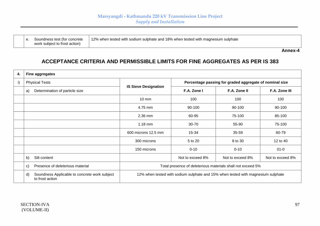
Marsyangdi - Kathmandu 220 kV Transmission Line Project Supply and Installation
SECTION-IVA
(VOLUME-II)
97
e. Soundness test (for concrete work subject to frost action)
12% when tested with sodium sulphate and 18% when tested with magnesium sulphate
Annex-4
ACCEPTANCE CRITERIA AND PERMISSIBLE LIMITS FOR FINE AGGREGATES AS PER IS 383
4. Fine aggregates
i) Physical Tests IS Sieve Designation
Percentage passing for graded aggregate of nominal size
a) Determination of particle size F.A. Zone I F.A. Zone II F.A. Zone III
10 mm 100 100 100
4.75 mm 90-100 90-100 90-100
2.36 mm 60-95 75-100 85-100
1.18 mm 30-70 55-90 75-100
600 microns 12.5 mm 15-34 35-59 60-79
300 microns 5 to 20 8 to 30 12 to 40
150 microns 0-10 0-10 01-0
b) Silt content Not to exceed 8% Not to exceed 8% Not to exceed 8%
c) Presence of deleterious material Total presence of deleterious materials shall not exceed 5%
d) Soundness Applicable to concrete work subject to frost action
12% when tested with sodium sulphate and 15% when tested with magnesium sulphate

Marsyangdi - Kathmandu 220 kV Transmission Line Project Supply and Installation
SECTION-IVA
(VOLUME-II)
98
Annex-5
ACCEPTANCE CRITERIA AND PERMISSIBLE LIMITS FOR CONCRETE WORK
1) Concrete a) Workability Slump shall be recorded by slump cone method and it shall between 25-55 mm.
b) Compressive strength Three samples of 15 cm cube for 28 days compressive strength for all concrete works except pile foundation work shall be taken. For pile foundation works, six cubes, three for 7 days testing and balance three for 28 days testing shall be taken.
Notes :
1) For nominal (volumetric) concrete mixes, compressive strength for 1:1.5:3 (Sand: Fine aggreagate: Coarse aggregates) concrete shall be 265 kg/Sq.cm. for 28 days and for 1:2:4 nominal mix, it shall be 210 kg/Sq.cm.
2) ACCEPTANCE CRITERIA BASED ON 28 DAYS COMPRESSIVE STRENGTHS FOR NOMINAL MIX CONCRETE :
a) the average of the strength of three specimen be accepted as the compressive strength of the concrete, provided the strength of any individual cube shall neither be less than 70% nor higher than 130% of the specified strength.
b) If the actual average strength of accepted sample exceeds specified strength by more than 30%, Project Manager, if he so desires, may further investigate the matter. However, if the strength of any individual cube exceeds more than 30% of the specified strength, it will be restructed to 30% only for computation of strength.
c) If the actual average strength of accepted sample is equal to or higher than specified upto 30%, the strength of the concrete shall be considered in order and the concrete shall be accepted at full rates.
d) If the actual average strength of accepted sample is less than specified strength but not less than 70% of the specified strength, the concrete may be accepted at reduced rate at the discretion of Project Manager.
Marsyangdi - Kathmandu 220 kV Transmission Line Project Supply and Installation
SECTION-IVA
(VOLUME-II)
99
e) If the actual average strength of accepted sample is less than 70% of specified strength, the Engineer-in-charge shall reject the defective portion of work represent by sample and nothing shall be paid for the rejected work. Remedial measures necessary to retain the structure shall be taken at the risk and cost of contractor. If, however, the Engineer-in-charge so desires, he may order additional tests to be carried out to ascertain if the structure can be retained. All the charges in connection with these additional tests shall be borne by the Contractor.
General Notes :
1) This Field Quality Plan is not to limit the supervisory checks which are otherwise required to be carried out during execution of work as per drawings/Technical specifications etc.
2) Contractor shall be responsible for implementing/documenting the FQP. Documents shall be handed over by the contractor to Owner after the completion of the work.
3) Acceptance criteria and permissible limits for tests are indicated in the Annexure. However for further details/tests Owner specification and relevant Indian standards shall be referred.
4) Tests as mentioned in this FQP shall generally be followed.

Marsyangdi - Kathmandu 220 kV Transmission Line Project Supply and Installation
Section IV Volume – II Doc. No : CC-Consultancy-NEA-M-K-2015
1
TECHNICAL SPECIFICATIONS
SECTION- 4
TOWER, FOUNDATION, ERECTION, STRINGING AND COMMISSIONING OF LINE
1.0 Transmission Tower
1.1 General Description of the Tower
1.1.1 The towers shall be self-supporting, hot dip galvanised, latticed steel type & designed to carry the line conductors with necessary insulators, earth wires and all fittings under all loading conditions. Outline diagram of double circuit towers are enclosed with the Specification.
1.1.2 The tower shall be fully galvanised using mild steel or/and high tensile steel sections as specified in clause no. 1.6. Bolts and nuts with spring washer are to be used for connections.
1.1.3 The towers shall be of the following types:
A) Double Circuit towers (DA, DB, DC & DD/DDE)
B) Special towers.
1.2 Classification of Towers
1.2.1 The towers for 220 kV Lines are classified as given below:
__________________________________________________________________ Type of Deviation Typical Use
Tower Limit
__________________________________________________________________
DA 0 to 2 degrees To be used as tangent / suspension Tower with suspension insulator string
DB 2 to 15 degrees a) Angle towers with tension insulator string.
b) Also to be used for uplift force resulting from an uplift span up to 360m under broken wire conditions
c) Also to be used for Anti Cascading Condition.
DB 0 degree To be used as Section Tower.

Marsyangdi - Kathmandu 220 kV Transmission Line Project Supply and Installation
Section IV Volume – II Doc. No : CC-Consultancy-NEA-M-K-2015
2
DC 15 to 30 degrees a) Angle tower with tension insulator string.
b) Also to be used for uplift forces resulting from an uplift span up to 360m under broken wire condition.
c) Also to be used for anti cascading condition. DC 0 deg. To be used as Section tower. DD 30 - 60 deg. a) Angle tower with tension insulator string. b) Also to be used for uplift forces resulting from an uplift span up to 600m under broken wire condition.
c) Dead end with 0 deg to 15 deg deviation both on line side and sub-station side (slack span)
DDE 0 deg. a) Complete dead end.
b) For river crossing anchoring with longer wind span & 0 deg. deviation on crossing span side and 0 deg to 30 deg. deviation on other side.
__________________________________________________________________
Notes
i) All above towers shall be designed for single circuit strung condition also considering that all conductors and earthwire of one circuit would be placed on one side of tower.
ii) All above towers can also be used for longer span with smaller angle of deviations without infringement of ground clearance.
iii) The above table provides indicative classification of Towers. Tower spotting data for various towers to be used in the transmission lines shall be given by the contractor during execution stage.
1.2.2 Towers for Major Crossings
The above towers shall also be used with suitable modifications for very long spans (spans more than that of given in clause no. 1.3) which can not be crossed by normal tower with extensions as given in clause.no.1.2.3 like valley and river crossings etc. These Towers shall be developed by strengthening the above DA, DB, DC and DD type towers as per the site requirement. Additional weight of tower due to strengthening shall be paid on pro-rata basis derived from the

Marsyangdi - Kathmandu 220 kV Transmission Line Project Supply and Installation
Section IV Volume – II Doc. No : CC-Consultancy-NEA-M-K-2015
3
quoted price and final weight of the standard (+/- 0) tower after successful testing.
1.2.3 Extensions
1.2.3.1 The Double Circuit towers shall be designed so as to be suitable for adding –3M, -1.5M, 1.5M, 3M, 4.5M, 6M, 7.5M and 9M body extensions / leg extensions for maintaining adequate ground clearances without reducing the factor of safety (actual stress /allowable stress) available for the members of tested extensions in any manner. Reference drawing for leg extension arrangement is enclosed in the Bid Document.
1.2.3.2 The provision for addition of 18/25M body extension to tower types DA and DD is also kept. For Power Line Crossing or any other obstacle, tower types DA or DD can be used with 18/25 M extensions depending, upon the merit of the prevailing site condition. The maximum reduced spans for DA and DD type towers shall be mentioned in the tower spotting data. However this shall, in no case be less than 250 meters. Payment for the additional weight due to 18/25M extension shall be made as described in clause no. 1.2.2.
1.2.3.3 The towers shall be designed for providing unequal leg extensions with maximum difference between the shortest and the longest leg of 3M for DA tower and 6M for DB, DC & DD towers. These unequal leg extensions to be provided in the design shall be used during tower spotting / execution stage to optimise the benching / revetment requirement.
1.2.3.4 In situations where difference in leg differential does not suit the standard unequal leg extension provisions on the towers mentioned above, suitable chimney extensions shall be provided to reduce benching/revetment requirement. Additional volumes of foundation due to chimney extensions shall be paid on pro-rata basis derived from the quoted price and final volumes of the standard foundation of same classification for that tower.
1.2.3.5 The leg extensions, unequal leg extensions, chimney extensions and / or a combination of these suitable for a tower location shall be selected on the basis of techno-economics evaluation.
1.2.3.6 All above body / leg extension provisions to towers shall be treated as part of normal tower only.
1.3 Spans
1.3.1 Design Span or Normal Span
The Design Span or Normal Ruling Span of the line is 350m for 220KV transmission line.

Marsyangdi - Kathmandu 220 kV Transmission Line Project Supply and Installation
Section IV Volume – II Doc. No : CC-Consultancy-NEA-M-K-2015
4
1.3.2 Wind Span
The wind span is the sum of the two half spans adjacent to the tower under consideration. For normal horizontal spans this equals to normal ruling span.
1.3.3 Weight span
The weight span is the horizontal distance between the lowest point of the conductors on the two spans adjacent to the tower. For spotting of structures, the span limits are given in Table 1.1 below
TABLE 1.1
TOWER TYPE NORMAL CONDITION BROKEN WIRE CONDITION
MAX. (m) MIN. (m) MAX. (m) MIN. (m)
DA 600 200 360 100
DB, DC 600 -600 360 -360
DD 1000 -1000 600 -600
1.3.4 In case at certain locations where actual spotting spans exceed the design spans
and cross-arms and certain members of towers are required to be modified/ reinforced, in that case design, structural & shop drawings for the modified/ reinforced towers will be prepared by the Contractor as per requirement on basis of approved line diagram without any additional financial implications to the Employer for the design and drawings.
1.4 Electrical Clearances
1.4.1 Ground Clearance
The minimum ground clearance from the bottom conductor shall not be less than 7500 mm for 220KV lines at the maximum sag conditions i.e at 80°C and still air.
a) An allowance of 150mm shall be provided to account for errors in stringing.
b) Conductor creep shall be compensated by over tensioning the conductor at a temperature of 26°C, lower than the stringing temperature for ACSR “MOOSE” for 220KV transmission lines.
1.4.3 Power Line Crossing
Minimum clearance between power lines to power line crossing should be 4580 mm.

Marsyangdi - Kathmandu 220 kV Transmission Line Project Supply and Installation
Section IV Volume – II Doc. No : CC-Consultancy-NEA-M-K-2015
5
1.4.4 Live Metal Clearance
The minimum live metal clearance to be provided between the live parts and steel work of superstructure shall be as given in Table 1.2
TABLE 1.2
DESCRIPTION SWING ANGLE LIVE METAL CLEARENCE -------------------- --------------------- ----------------------------------- 2000 M EL ----------------------------------- Suspension String NIL 2400 mm (Single / Double) 15 Degree 2230 mm 30 Degree 2060 mm 45 Degree 1885 mm Tension String -- 2400 mm (Single / Double) Jumper NIL 2400 mm 10 Degree 2400 mm 20 Degree 2060 mm
NOTE: in case of pilot insulator strings, the angle of swing of the jumper alongwith the pilot string shall be considered as 15 deg.
1.4.5 Bidder shall adopt same cross arm design where jumper is projecting outside of cross-arm for DD/DDE type tower, used as dead end and angle tower.
1.4.6 For computing the live metal clearances the dimensions of Single Suspension, Double Suspension, Single Suspension Pilot, Single Tension and Double Tension strings shall be taken as given in enclosed drawings. The design of the tower shall be such that it should satisfy all the above conditions when clearances are measured from any live point of the strings. As the Contractor may use & supply insulator strings with disc insulators or long rod insulators or polymer insulators, the tower design shall be such that it satisfies the clearance requirements in that particular case.
1.4.7 Cross arm projections for Dead end towers shall be fixed in such a way that it can accommodate a condition of 15 degree deviation of conductors towards tower at both Left and Right side cross arms on slack span side and 0-15 degrees deviation on line side.
1.4.8
Marsyangdi - Kathmandu 220 kV Transmission Line Project Supply and Installation
Section IV Volume – II Doc. No : CC-Consultancy-NEA-M-K-2015
6
1.4.9 Angle of Shielding
The angle of shielding is defined as the angle formed by the line joining the centre lines of the earthwire and outer power conductor in still air at tower supports, to the vertical line through the centre line of the earthwire. Bidders shall design the tower in such a way that the angle of shielding does not exceed 20 deg for all towers. The drop of the earthwire clamp equal to 150 mm should be considered while calculating the minimum angle of protection.
1.4.9 Mid Span Clearance
The minimum vertical mid span clearance between the earthwire and the nearest power conductor shall not be less than 8.5 metres, which shall mean the vertical clearance between earthwire and the nearest conductor under all temperatures and still air condition in the normal ruling span. Further, the tensions of the eathwire and power conductor, shall be so co-ordinated that the sag of earthwire shall be at least 10% less than that of power conductors under all temperature loading conditions.
1.5 Normal Loading Conditions
1.5.1 Loads at Conductor and Earthwire Points
Employers has calculated the ultimate external loadings at conductor and earthwire points and are enclosed along with the specification. The Contractor shall develop the tower designs based on the loadings given by the Employer only.
1.5.2 Wind Loads on Tower Body
The wind load on tower body shall be calculated by the Contractor as per clause 9.1 of IS 802(Part 1/Sec 1):1995. The following data shall be considered for calculating wind load on tower body.
a) Dynamic reference wind pressure shall be considered as 71.5 Kg/m2.
b) Terrain category shall be considered as 2.
c) The angle of incidence of Wind θ (Theta) = 0 Degree.
1.5.3 Maximum Tension
1.5.3.1 Max. tension shall be based on either
a) at 0 deg C with 36 percent full wind pressure, or
b) at 32 deg C with full wind pressure whichever is more stringent.

Marsyangdi - Kathmandu 220 kV Transmission Line Project Supply and Installation
Section IV Volume – II Doc. No : CC-Consultancy-NEA-M-K-2015
7
1.5.3.2 Employer has calculated sag tension calculation for a normal span of 350 meters. Sag tensions calculations are furnished alongwith the specification.
1.5.3.3 The initial conductor and earthwire tension (maximum) at 32ºC and without wind shall be 22% of the ultimate tensile strength of the conductor and 20% of the ultimate tensile strength of the earthwire.
1.5.4 Limiting Tensions of Conductor & Earthwire
The ultimate tension of conductor and earthwire shall not exceed 70 per cent of the ultimate tensile strengths.
1.5.5 Broken Wire Condition
1.5.5.1 Suspension Tower Type DA
Any one phase (both sub-conductors) or earthwire broken; whichever is more stringent for a particular member.
1.5.5.2 Tension Tower Type DB and DC
Breakage of any two phases (both sub-conductors)on the same side and on the same span or breakage of any one phase (both sub-conductors)and one earthwire on the same side and same span whichever combination is stringent for a particular member.
1.5.5.3 Tower Type DD
Breakage of all the three phases (both sub-conductors) on the same side and on the same span or breakage of two phases (both sub-conductors) and one earthwire on the same side and on the same span, whichever combination is more stringent for a particular member.
1.6 Design of Towers
1.6.1 Design Criteria
Towers shall be designed based on spans and clearances as per Clause 1.3 & 1.4 and loading conditions as per Clause 1.5 above.
1.6.2 Design Temperatures
The following temperature range for the conductors and ground wires shall be adopted for line design:
i) Minimum Temperature : 0 deg.C
ii) Every day temperature of conductor : 32 deg.C
iii) Max. temperature of

Marsyangdi - Kathmandu 220 kV Transmission Line Project Supply and Installation
Section IV Volume – II Doc. No : CC-Consultancy-NEA-M-K-2015
8
a) Conductor : 80 deg.C
b) Earthwire exposed to sun : 53 deg.C
1.6.3 Conductor and Earthwire Configuration
For double circuit towers the three phases shall be in vertical formation. The phase to phase spacing for conductors shall be not less than 4.9 meters vertically for DA/DB/DC towers and 8.30 meters for DD tower. However, the minimum horizontal separation between phase conductors of two circuits shall be 8.4 meters.
1.6.4 Redundant Design
1.6.4.1 All redundant in the tower are to be triangulated.
1.6.4.2 All bracing and redundant members of the towers which are horizontal or inclined up to 15º from horizontal shall be designed to withstand an ultimate vertical load of 1500 N considered acting at centre independent of all other loads. The bending moment for designing of redundant members shall be considered as WL/4 irrespective of end connections and continuity. The contractor has to furnish the calculations for the same (where W is ultimate load of 1.5 kN and ‘L’ is the length of redundant from bolt to bolt).
1.6.4.3 All redundant shall be designed individually for 2.5% of maximum axial load of connecting members (i.e. leg members, bracing members etc.) as per drawing no.K-D/220kV/0013. The contractor has to furnish the calculations for the same.
1.6.4.4 Connection of single Redundant to leg member having a section of 110 x 110 x 10 and above shall be done with minimum of 2 bolts.
1.6.5 THICKNESS OF MEMBERS
The minimum thickness of angle sections used in the design of towers, unless otherwise specified elsewhere in this Specification, shall be kept not less than the following values:
a) Main corner leg members including the : 5 mm earthwire peak and main cross arm b) For all other members : 4 mm
1.6.6 BOLTS AND NUTS
1.6.6.1 The minimum bolt spacing and rolled edge distance and sheared edge distance from the centers of bolt holes to be maintained are given in Table 1.3

Marsyangdi - Kathmandu 220 kV Transmission Line Project Supply and Installation
Section IV Volume – II Doc. No : CC-Consultancy-NEA-M-K-2015
9
TABLE 1.3
Diameter of Hole Min. Bolt Min. Rolled Min. Sheared Bolt Diameter Spacing Distance Edge Distance (mm) (mm) (mm) (mm) (mm) ------------------------------------------------------------------------------------------------------
16 17.5 40 20 23
24 25.5 60 33 38
------------------------------------------------------------------------------------------------------
Bolts sizes mentioned above shall only be used. The minimum width of the flanges without bolt holes shall be 30 mm
1.6.6.2 For the purpose of calculating shearing stress and bearing stress for bolts clause 5.4 of IS: 802 (Part-1/Sec 2):1992 shall be referred.
1.6.7 SLENDERNESS RATIO
Slenderness ratio for members shall be computed in accordance with clause 6.4 of IS: 802 (Part-1/Sec 2):1992.
1.6.7.1 802(Part-1) 1977. Slenderness ratio for compression and tension members shall not exceed the values specified therein.
1.6.7.2 The following maximum limit of the slenderness ratio i.e. the ratio of unsupported length of the section in any plane to the appropriate radius of gyration will be adopted:
VALUE OF KL/R
a) For main corner leg members including the corner members of earthwire peak and the lower corner 120
members of the cross-arms b) For other members having calculated stresses 200
c) For redundant members 250
d) For members having tensile stress only 375
1.6.8 ERECTION STRESS
Where erection stress combined with other permissible co-existent stresses could produce a working stress in any members appreciably above the specified

Marsyangdi - Kathmandu 220 kV Transmission Line Project Supply and Installation
Section IV Volume – II Doc. No : CC-Consultancy-NEA-M-K-2015
10
working stress, such other provision are to be made as may be necessary to bring the working stress within the specified limit.
1.6.9 STRUCTURAL ARRANGEMENT OF MEMBERS IN A TOWER
1.6.9. Lifting Points shall be provided in the tension tower and shall be designed for a load of 1020 Kgs assumed as acting at a 600 mm distance from the tip of the cross arm.
1.6.9.2 Internal angle between two members shall not be less than 15 degrees.
1.6.10 Design Calculation and Drawings
1.6.10.1 The following design calculation and drawings are required to be furnished to the Employer:
A) Alongwith the bid:
Detailed design calculations and drawings for DD type tower only.
B) After award of contract:
The Contractor shall submit detailed design of tower & extension alongwith stress diagram / computer output together with sample calculations for few critical members etc., stub templates and loading / rigging arrangement of tower testing to enable the Employer to make a preliminary check regarding structural stability of tower (before) tests.
1.6.10.2 After successful testing of tower and subsequent approval of design, drawings and bill of materials, the Contractor shall furnish the following in ten (10) copies to the Employer for necessary distribution with in fifteen(15) days after approval of drawings:
a) Detailed design calculation and drawing for towers and foundations.
b) Detailed structural drawings indicating section size, length of members, sizes of plates along with hole to hole distance & joint details etc.
c) Bill of materials, indicating cutting and bending details against each member.
d) Shop drawings showing all details relevant to fabrication.
e) All the drawings for the tower accessories.
1.6.10.3 The Contractor is required to submit four copies of the drawings as mentioned in clause 1.6.10.2 for Employer’s approval. While submitting the designs, structural drawings bill of materials and any other drawing pertaining to the subject transmission line, the Contractor shall clearly indicate on each drawing

Marsyangdi - Kathmandu 220 kV Transmission Line Project Supply and Installation
Section IV Volume – II Doc. No : CC-Consultancy-NEA-M-K-2015
11
NEA Specification No., Name of the transmission line and project , letter reference No. and date on which the submission are made. The same practice is also to be followed while submitting distribution copies.
1.6.10.4 The design and drawings as covered in clause 1.6.10.1 (B) above shall be approved / commented by the Employer as the case may be within twenty eight (28) days of receipt of design / drawings in NEA office. If the design / drawings are commented by the Employer, the Contractor shall submit revised designs / drawings with in fifteen (15) days of date of issue of comments.
1.6.10.5 The Contractor is required to furnish the progress of submissions and approvals of designs and drawings on twenty fifth day of every month till the completion of all the design activities..
The details shall include description of design / drawing, schedule date of submission, actual date of submission schedule date of approval ,actual date of approval, schedule date of submission of distribution copies, actual date of submission of distribution copies, schedule date of tower test, actual date of tower test and ‘Remarks’ column. Provision of six additional columns shall also be made in the above progress report to indicate date of comments issued by the Employer and details of submission of revised designs / drawings.
1.6.10.6 The tower accessories drawings like name plate, danger plate, phase plate, circuit plate, anticlimbing device, step bolt, D-shackle etc. shall also be prepared by the Contractor and shall be submitted to the Employer, in three copies, along with one reproducible, for record. These drawings shall be prepared in A4 size only.
1.6.10.7 All the drawings shall have a proper name plate clearly displaying the name of Employer on right hand bottom corner. The approval for exact format of the nameplate shall be obtained by the successful bidder from the Employer for adopting the same on all the drawings. Also all the drawings shall carry the following statement and shall be displayed conspicuously on the drawing:
WARNING: THIS IS PROPRIETORY ITEM AND DESIGN RIGHT IS STRICTLY RESERVED WITH NEPAL ELECTRICITY AUTHORITY (NEA). UNDER NO CIRCUMSTANCES THIS DRAWING SHALL BE USED BY ANYBODY WITHOUT PRIOR PERMISSION FROM NEA IN WRITING.
1.7 Materials
1.7.1 Tower Steel Sections
1.7.1.1 IS Steel Sections of tested quality of conformity with IS:2062:2011 grade E250 (Designated Yield Strength. 250 MPa) and/ or grade E350 (Designated Yield Strength 350 MPa) are to be used in towers, extensions, stubs and stub setting

Marsyangdi - Kathmandu 220 kV Transmission Line Project Supply and Installation
Section IV Volume – II Doc. No : CC-Consultancy-NEA-M-K-2015
12
templates. For Snow Zone towers MS & HT Steel Sections shall conform to E250 Grade-C & E350 Grade-C respectively. The Contractor can use other equivalent grade of structural steel angle sections and plates conforming to latest International Standards viz BSEN 10025. However, use of steel grade having designated yield strength more than that of EN 10025 grade S355 JR/JO (designated yield strength 355 MPa) is not permitted, unless otherwise indicated in this specification.
1.7.1.2 Steel plates below 6mm size exclusively used for packing plates/packing washers produced as per IS : 1079 (Grade-0) are also acceptable. However, if below 6mm size plate are used as load bearing plates viz gusset plates , joint splices etc. the same shall conform to IS : 2062 or equivalent standard meeting mechanical strength/metallurgical properties corresponding to grade E250 or above grade (designated yield strength not more than 355MPa), depending upon the type of grade incorporated into design. Flats of equivalent grade meeting mechanical strength/ metallurgical properties may also be used in place of plates for packing plates/ packing washers. The chequered plates shall conform to IS : 3502. SAILMA 350HI grade plate can also be accepted in place of HT plates (EN 10025 grade S355 JR/JO / IS 2062:2011 – grade E350, as applicable) provided SAILMA 350HI grade plate meet all the mechanical properties of plate as per EN 10025 grade S355 JR/JO (designated yield strength 355 MPa) / IS 2062: 2011 – grade E350.
1.7.1.3 For designing of towers, preferably rationalised steel sections shall be used. During execution of the project, if any particular section is not available, the same shall be substituted by higher section at no extra cost to Employer and the same shall be borne by the Contractor. However, design approval for such substitution shall be obtained from the Purchaser before any substitution.
1.7.2 Fasteners: Bolts, Nuts and Washers
1.7.2.1 All tower members shall be joined together with Bolts and nuts. All hexagonal bolts and nuts shall conform to IS-12427. They shall have hexagonal head and nuts, the heads being forged out of the solid, truly concentric, and square with the shank, which must be perfectly straight.
All bolts and nuts shall be galvanised as per IS:1367 (Part-13) / IS:2629 .
1.7.2.2 The bolt shall be of 16 / 24 mm diameter and of property class 5.6 as specified in IS:1367 (Part-III) and matching nut of property class 5.0 as specified in IS:1367 (Part-VI).
1.7.2.3 Bolts up to M16 and having length up to 10 times the diameter of the bolt should be manufactured by cold forging and thread rolling process to obtain good and reliable mechanical properties and effective dimensional control. The shear strength of bolts for 5.6 grade should be 310 MPa minimum as per

Marsyangdi - Kathmandu 220 kV Transmission Line Project Supply and Installation
Section IV Volume – II Doc. No : CC-Consultancy-NEA-M-K-2015
13
IS:12427. Bolts should be provided with washer face in accordance with IS: 1363 (Part-I) to ensure proper bearing.
1.7.2.4 Nuts for hexagonal bolts should be double chamfered as per the requirement of IS: 1363 Part-III. It should be ensured by the manufacturer that nuts should not be over tapped beyond 0.4mm oversize on effective diameter for size up to M16.
1.7.2.5 Fully threaded bolts shall not be used. The length of bolts shall be such that the threaded portion will not extend into the place of contact of the members.
1.7.2.6 All bolts shall be threaded to take the full depth of the nuts and threaded for enough to permit firm gripping of the members, but not further. It shall be ensured that the threaded portion of each bolt protrudes not less than 3mm and not more than 8mm when fully tightened. All nuts shall fit tight to the point where the shank of the bolt connects to the head.
1.7.2.7 Flat and tapered washers shall be provided wherever necessary. Spring washers shall be provided for insertion under all nuts. These washers shall be steel electro-galvanised, positive lock type and 3.5mm in thickness for 16mm diameter bolt and 4.5 mm for 24 mm bolt.
1.7.2.8 To avoid bending stress in bolts or to reduce it to minimum, no bolt shall connect aggregate thickness of members more than three (3) times its diameter.
1.7.2.9 The bolt positions in assembled towers shall be as per IS: 5613 (Part-II / Section 2) -1976.
1.7.2.10 Bolts at the joints shall be so staggered that nuts shall be tightened with spanners without fouling.
1.7.2.11 To ensure effective in-process Quality control it is desirable that the manufacturer should have in house testing facility for all tests like weight of zinc coating, shear strength and other tests etc. The manufacturer should also have proper Quality Assurance System which should be in line with the requirement of this specification and IS: 14000 series Quality System Standard.
1.8 Tower Accessories
Arrangement shall be provided for fixing of all tower accessories to the tower at a height between 2.5 meters and 3.5 meters above the ground level.
Marsyangdi - Kathmandu 220 kV Transmission Line Project Supply and Installation
Section IV Volume – II Doc. No : CC-Consultancy-NEA-M-K-2015
14
1.8.1 Step Bolts & Ladders
Each tower shall be provided with step bolts conforming to IS: 10238 of not less than 16mm diameter and 175 mm long spaced not more than 450mm apart and extending from 2.5 meters above the ground level to the top of the tower. However, the head diameter shall be 50mm as indicated in the enclosed drawing. For double circuit tower the step bolt shall be fixed on two diagonally opposite legs up to top of the towers. Each step bolt shall be provided with two nuts on one end to fasten the bolt securely to the tower and button head at the other end to prevent the feet from slipping away. The step bolts shall be capable of withstanding a vertical load not less than 1.5 KN. For special towers, where the height of the super structure exceeds 50 meters, ladders along with protection rings as per the Employer’s approved design shall be provided in continuation of the step bolts on one face of the tower from 30 meters above ground level to the top of the special structure. From 2.5m to 30m height of super structure step bolts shall be provided. Suitable platform using 6mm thick perforated chequered plates along with suitable railing for access from step bolts to the ladder and from the ladder to each cross-arm tip and the ground wire support shall also to be provided. The platform shall be fixed on tower by using counter-sunk bolts.
1.8.2 Insulator String Attachments
a) For the attachment of suspension Insulator string, a suitable dimensioned swinging hanger on the tower shall be provided so as to obtain specified clearances under respective swinging condition of the strings. The hanger, extensions links, D-shackles etc. as required and considered in the design of the tower shall have minimum ultimate tensile strength of 240KN for double suspension string for 220KV suspension towers. The design and supply of hanger, D-shackles, strain plates etc. are also in the scope of Contractor.
b) At tension towers, strain plates of suitable dimensions under each cross-arm tip, shall be provided for taking the hooks or D-shackles of the tension insulator strings. Full details of the attachments shall be provided by the contractor. To achieve requisite clearances, if the design calls for providing extra D-shackles, link plate etc. before connecting the insulator string the same shall be supplied by the Contractor.
1.8.3 Earth wire Clamp Attachments a) Suspension Clamps

Marsyangdi - Kathmandu 220 kV Transmission Line Project Supply and Installation
Section IV Volume – II Doc. No : CC-Consultancy-NEA-M-K-2015
15
Earth wire suspension clamps will be supplied by the contractor. The detailed drawing shall be submitted by the Contractor for Employer’s approval. The Contractor shall also supply U- bolts, D-shackles wherever required.
b) Tension Clamps
Earth wire peaks of tension towers shall be provided with suitable plates to accommodate the shackle of tension clamps. The contractor shall also supply the U-bolts wherever required and take Employer’s approval for details of the attachments before the mass fabrication.
1.8.4 Anti Climbing Device
Barbed wire type anti climbing device, as per enclosed drawing shall be provided and installed by the Contractor for all towers. The barbed wire shall conform to IS-278 (size designation A1). The barbed wires shall be given chromating dip as per procedure laid down in IS: 1340.
1.8.5 Danger, Number, Circuit and Phase plate
Danger plates, Number plates, Circuit plates and Phase plates shall be provided and installed by the Contractor.
a) Each tower shall be fitted with a danger plate, number plate and one set of phase plates for double circuit tower. Circuit plates shall be provided on all The Double Circuit towers.
b) The letters, figures and the conventional skull and bones of danger plates shall conform to IS-2551 and shall be in a signal red on the front of the plate.
c) The corners of the danger, number and circuit plates shall be rounded off to remove sharp edges.
d) The letters of number and circuit plates shall be red enameled with white enameled background.
1.8.6 Aviation Requirements
1.8.6.1 Aviation requirements viz Span marker, night marker (obstruction light) and painting of towers conforming to IS: 5613 shall be in the scope of Contractor, wherever indicated in BPS.
1.8.6.2 Night Markers (Obstruction lights)
1.8.6.2.1 The scope of night markers covers the design, manufacture, testing at manufacturers works, if any, supply, delivery, erection, testing and

Marsyangdi - Kathmandu 220 kV Transmission Line Project Supply and Installation
Section IV Volume – II Doc. No : CC-Consultancy-NEA-M-K-2015
16
commissioning of medium intensity, low intensity, lights along with storage battery & solar panel, control panel, cables, clamps other accessories etc. as per the provision of IS-5613 (Part-II/ section-I), 1989, amendment no. 1, July’94 regarding night & day visual aids for denoting transmission line structures as per the requirement of directorate of flight safety.
1.8.6.2.2 The detail of each component of medium intensity, low intensity lights & associated accessories to be provided on the towers shall be as per the technical specifications given in the preceding clauses and IS/ICAO, International Standards recommended practices.
1.8.6.2.3 One set of Aviation Lights shall consist of one medium intensity light & two/four (as applicable) low intensity lights along with all accessories such as solar panel, control panel, batteries, cables etc.
1.8.6.2.4 Medium Intensity Light
Medium Intensity light shall be provided on the top of each tower. The medium light should have night time intensity as per ICAO requirements in international Standards Recommended Practices. The light on top of the structure should flash at the rate of 20 sequences per minute. The effective intensity during night time for the medium flashing light shall be 1600 CD. The light shall conform to ICAO requirements/BS 3224a and shall have weather protection conforming to IP-55.
The above lights conforming to ICAO specifications flashing red lights shall be DC operated through a suitably sized battery bank at the operating voltage 12V/24V DC. The burning life of the lamps shall be maximum possible in view of the maintenance hazard of H.T. live but in no case it should be less than 15,000 burning hours. In case of failure of the lamp before 15,000 burning hours, the same shall have to be replaced by the Contractor free of cost even if the pendency of contract expires. The light shall be equipped with radio suppression facility conforming to BS800 in order to avoid any interference with signals of PLCC etc.
1.8.6.2.5 Low Intensity Lights
Two/four (as applicable) nos. of low intensity lights are required to be put on each of the towers. Placement drawing for the same shall be submitted by the bidder Contractor.
The light shall be stationary lamp with minimum effective intensity of 10 CD. of red light. The lamps shall conform to the ICAO requirement/relevant BS and shall have weather protection of minimum IP-55 class.

Marsyangdi - Kathmandu 220 kV Transmission Line Project Supply and Installation
Section IV Volume – II Doc. No : CC-Consultancy-NEA-M-K-2015
17
Two/four nos. of L.I. lamp required for each tower shall be operated through a suitable size common battery bank solar panel as per the requirement of operating voltage and load current of the type of lamps being offered.
The burning life of the lamps shall be maximum possible in view of the maintenance hazard of H.T live line, but in no case it should be less than 15,000 burning hours. In case of failure of the lamp before 15,000 hrs, the same shall have to be replaced by the Contractor free of cost even if the pendency of contract expires. Performance certificate of the lamps to be offered shall be furnished by the Contractor.
The low intensity lamp shall not generate any R.F. which can interfere with the PLCC signals.
1.8.6.2.6 Storage Battery
Storage Battery required for the above purpose shall be sealed maintenance free, valve regulate lead acid and suitable for mounting on the top of the transmission line towers. Contractors shall offer the most optimum capacity of the Battery Bank at 120 hour discharge rate (considering 80 % percentage usage) matching with the load requirement of the type of lamps being offered including any power loss in the associated cables. The battery sizing shall conform to JISC 8707/relevant Indian Standard or any other internationally recognized standard. The battery shall be hermetically sealed explosion proof and self-resealing type and free from orientation constraints. The working temperature ranges shall be minimum 0 degree centigrade and maximum 50 degree centigrade. Performance certificate of the offered batteries shall be submitted by the Contractor.
1.8.6.2.7 Battery Box
The battery box suitable for mounting on 220kV power transmission tower shall be robust construction suitable to accommodate desired number of SOLAR BATTERIES WITH proper clearance between the batteries. The sides and the top of the battery box shall be made from MS sheets not less than 14 SWG thickness duly mounted on MS angle frame. The bottom of the battery box shall have suitably designed MS structure to freely hold the total weight of the batteries. The batteries should be placed on insulated base with proper drainage holes. Lifting lugs shall be provided. Dust and vermin proof lockable doors shall be provided for safety and easy access to the batteries for the maintenance. The battery box should incorporate the design for proper ventilation system in order to prevent a gas concentration inside the box. The ventilation opening shall be protected against rain/splash water and dust. The inside of the battery box shall be lined with insulating polyurethane plating and the exterior painted with weather proof polyurethane paint. The cable entry into the battery box shall be through suitable cable glands.

Marsyangdi - Kathmandu 220 kV Transmission Line Project Supply and Installation
Section IV Volume – II Doc. No : CC-Consultancy-NEA-M-K-2015
18
1.8.6.2.8 Solar Modules
Solar module required for the system shall be suitable for mounting on the transmission line towers and shall be designed for high performance, maximum reliability and minimum maintenance and shall be installed below bottom cross arms levels. The solar modules shall be IP 55 grade protection class. These should be highly resistant to water, abrasion, nail, impact and other environmental factors.
These should be placed on the tower at a most optimum angle so as to harness the maximum solar energy and facilitate self cleaning and shall conform to relevant Indian/International Standards.
Module mounting frames shall be weather proof suitable for mounting on tall towers. Details of mounting frames shall be furnished by the Contractor.
Junction box shall be provided with weather proof hinged lid with provision for cable glands entry and protections grade of class IP-55.
The Contractor shall submit the basis of selecting the numbers of solar modules.
The provision for design, supply & erection of mounting arrangements for photovoltaic modules on the transmission towers in a suitable manner to harness maximum solar energy shall be in the scope of the Contractor.
Provision for design, supply & erection of resting platform for the erection of battery bank in a closed enclosure with safety arrangement on the transmission towers shall also be in the scope of the Contractor the design and load consideration for safety of towers due to additional plate form shall be kept in view while designing, selecting the above.
1.8.6.2.9 Control Panels
Control panels shall consist of solar charge controller, flasher unit, sensor, isolator, MCB, Voltmeter, Ammeter and other control gears. Panel enclosure shall be fabricated out of 14 SWG CRCA sheet and thoroughly treated and painted. Suitable neoprene rubber gasket and pad locking device shall be provided and the protection class shall be of IP-55 class.
The Solar charge controller shall be most efficient and preferably fully solid state. It shall be provided with protection to load against increase in temperature, Surge, automatic low voltage and automatic disconnection and reconnection during high inrush current and normalcy respectively.
The flash regulator shall be provided for regulating light flashing. The same shall be completely solid state and provided with flash rate set points. The protection against overload current shall also be provided.

Marsyangdi - Kathmandu 220 kV Transmission Line Project Supply and Installation
Section IV Volume – II Doc. No : CC-Consultancy-NEA-M-K-2015
19
Necessary sensor/timer shall be provided in the system to “switch on” the light automatically in the evening and poor visibility period and switch off the same during day time and normal visibility period.
1.8.6.2.10 Cables, Cable Glands, Conduits and Accessories
The cable to be supplied and erected shall be of multi strands copper conductor, weather proof, PVC insulated PVC sheathed, armoured 1.1 KV grade. The same shall conform to IS:1554.
All the cable accessories such as thimble, glands etc. shall be in the scope of supply and erection of the Contractor.
Supply and erection of all the PVC conduits and accessories shall be in the scope of the contract. All the conduit and accessories shall be as per the relevant ISS or ISI brand.
The inter-connection cable/conduit will be clamped in a secured manner with the tower members and any interconnection should be made only inside the environmentally protected junction box.
1.8.6.2.11 Earthing
All the installations on the tower shall be securely and properly earthed with the tower body by using flexible copper braided wire. Cost of earthing material shall deemed to be included in the total cost.
1.9 Tower Fabrication
The fabrication of towers shall be in conformity with the following:
1.9.1 Except where hereinafter modified, details of fabrication shall conform to IS: 802 (Part-II) or the relevant international standards.
1.9.2 Butt splices shall be used and the inside angle and outside plate shall be designed to transmit the load. Inside cleat angle shall not be less than half the thickness of the heavier member connected plus 2mm. Lap splice may be used for connecting members of unequal sizes and the inside angle of lap splice shall be rounded at the heel to fit the root radius of the outside angle. All the splices shall develop full strength in the member connected through bolts. Butt as well as lap splice shall be made as above and as close to the main panel point as possible.
1.9.3 Joints shall be so designed as to avoid eccentricity as far as possible. The use of gusset plates for joining tower members shall be avoided as far as possible. However, where the connections are such that the elimination of the gusset

Marsyangdi - Kathmandu 220 kV Transmission Line Project Supply and Installation
Section IV Volume – II Doc. No : CC-Consultancy-NEA-M-K-2015
20
plates would result in eccentric joints, gussets plates and spacers plates may be used in conformity with modern practices. The thickness of the gusset plates, required to transit stress shall not be less than that of members connected.
1.9.4 The use of filler in connection shall be avoided as far as possible. The diagonal web members in tension may be connected entirely to the gusset plate wherever necessary to avoid the use of filler and it shall be connected at the point of intersection by one or more bolts.
1.9.2 The tower structures shall be accurately fabricated to connect together easily at site without any undue strain on the bolts.
1.9.3 No angle member shall have the two leg flanges brought together by closing the angle.
1.9.4 The diameter of the hole shall be equal to the diameter of bolt plus 1.5mm.
1.9.5 The structure shall be designed so that all parts shall be accessible for inspection and cleaning. Drain holes shall be provided at all points where pockets of depression are likely to hold water.
1.9.6 All identical parts shall be made strictly inter-changeable. All steel sections before any work is done on them, shall be carefully leveled, straightened and made true to detailed drawings by methods which will not injure the materials so that when assembled, the adjacent matching surfaces are in close contact throughout. No rough edges shall be permitted in the entire structure.
1.9.7 Drilling and Punching
1.9.7.1 Before any cutting work is started, all steel sections shall be carefully straightened and trued by pressure and not by hammering. They shall again be trued after being punched and drilled.
1.9.7.2 Holes for bolts shall be drilled or punched with a jig but drilled holes shall be preferred. The punching may be adopted for thickness up to 16mm. Tolerances regarding punched holes are as follows:-
a) Holes must be perfectly circular and no tolerances in this respect are permissible.
b) The maximum allowable difference in diameter of the holes on the two sides of plates or angle is 0.8mm. i.e. the allowable taper in a punched holes should not exceed 0.8mm on diameter.
c) Holes must be square with the plates or angles and have their walls parallel.

Marsyangdi - Kathmandu 220 kV Transmission Line Project Supply and Installation
Section IV Volume – II Doc. No : CC-Consultancy-NEA-M-K-2015
21
1.9.7.3 All burrs left by drills or punch shall be removed completely. When the tower members are in position the holes shall be truly opposite to each other. Drilling or reaming to enlarge holes shall not be permitted.
1.9.8 Erection mark
1.9.8.1 Each individual member shall have erection mark conforming to the component number given to it in the fabrication drawings. The mark shall be marked with marking dies of 16mm size before galvanizing and shall be legible after galvanizing.
1.9.8.2 Erection Mark shall be A-BB-CC-DDD
A = Employer’s code assigned to the Contractors- Alphabet
BB = Contractor’s Mark-Numerical
CC = Tower Type Alphabet.
DDD = Number mark to be assigned by Contractor - Numerical.
Erection mark for high tensile steel members shall be prefixed by the letter “H”
1.10 Quantities and weights
1.10.1 The provisional quantity of towers & extensions are mentioned in the respective Schedule of Prices. Final quantities shall be determined after completion and approval of the tower spotting & check survey. The final quantities of tower shall be confirmed by the Employer based on the required quantities of various towers & extensions furnished by the Contractor after completion of final tower spotting & check survey. Hence, it will be responsibility of the Contractor to intimate the exact requirements of all towers and various line materials required for line immediately after the tower spotting & check survey.
The Employer reserves the right to order the final quantities including reasonable quantities of spares for which the rates quoted in the Bid shall be valid. Regarding quantity variation, the provisions of relevant clauses of SCC shall apply.
1.10.2 The estimated unit weight of each type of galvanized towers, stubs and leg extensions shall be furnished by the bidder. The weight of tower shall mean the weight of tower calculated by using the black sectional (i.e. un galvanized) weight of steel members of the size indicated in the approved fabrication drawings and bill of materials, without taking into consideration the reduction in weights due to holes, notches and bevel cuts etc. but taking into consideration the weight of the anticlimbing devices, D shackles, hangers, strain

Marsyangdi - Kathmandu 220 kV Transmission Line Project Supply and Installation
Section IV Volume – II Doc. No : CC-Consultancy-NEA-M-K-2015
22
plates, pack plates, gusset plates and pack washers etc. The weight of gusset plates shall mean the weight of its circumscribing rectangle, without taking into consideration the reduction in weights due to holes, notches etc.. For bolts and nuts along with spring washers and step bolts, the weight per tower shall be calculated from the bolt schedule applicable to each type of towers, stubs and leg extensions as approved by the Employer. The rate quoted by the bidder for supply of tower / tower parts is deemed to be inclusive of galvanising charges including the cost of zinc.
1.10.3 The contractor is permitted to get inspected and supply up to 2.5% extra
fasteners to take care of losses during erection. No payment shall be admissible for these extra supplies.
1.11 Galvanising 1.11.1 Fabricated Tower Parts & Stubs The tower parts, stubs and pack washers shall be hot dip galvanized .The
galvanization shall be done as per requirements of IS: 4759 after all fabrication work is completed. The contractor shall also take guidelines from the recommended practices for hot dip galvanizing laid down in IS 2629 while deciding and implementing galvanizing procedure. The mandatory requirements however, are specified herein.
Unless otherwise specified the fabricated tower parts and stubs shall have a
minimum overall Zinc coating of 610 gms per sq. m of surface except for plates below 5mm which shall have Zinc coating of 460 gms per sq. m of surface. The average zinc coating for sections 5mm & above shall be maintained as 87 microns and that for sections below 5mm shall be maintained as 65 microns.
The zinc coating shall be adherent, reasonably uniform, smooth, continuous
and free from imperfections such as black bare spots, ash rust stains, bulky white deposits / wet storage stains and blisters.
The surface preparation for fabricated tower parts and stubs for hot dip
galvanizing shall be carried out as indicated herein below:
(i) Degreasing & Cleaning of Surface: Degreasing and cleaning of surface, wherever required, shall be carried out in accordance with clause 4.1 of IS 2629-1985. After degreasing the article shall be thoroughly rinsed. However, if acidic degreasers are used rinsing is not required.

Marsyangdi - Kathmandu 220 kV Transmission Line Project Supply and Installation
Section IV Volume – II Doc. No : CC-Consultancy-NEA-M-K-2015
23
(ii) Pickling: Pickling shall be done using either hydrochloric or sulfuric acid as recommended at clause 4.3 of IS 2629 -1985. The actual concentration of the acids and the time duration of immersion shall be determined by the Contractor depending on the nature of material to be pickled. Suitable inhibitors also shall be used with the acids to avoid over pickling. The acid concentration, inhibitors used, and maximum allowable iron content shall form part of plant standard to be formulated and submitted to Purchaser along with Quality Assurance Program.
(iii) Rinsing: After pickling, the material shall be rinsed, preferably in running water
to remove acid traces, iron particles or any other impurities from the surface. Two rinse tanks are preferable, with water cascading from the second tank to the first to ensure thorough cleaning. Wherever single tank is employed, the water shall be periodically changed to avoid acid contamination, and removal of other residue from the tank.
(iv) Fluxing: The rinsed article shall be dipped in a solution of Zinc ammonium
chloride. The concentration and temperature of the flux solution shall be standardized by the contractor depending on the article to be galvanized and individual circumstances. These shall form part of plant standard to be formulated and submitted to Purchaser along with Quality Assurance Program. The specific gravity of the flux solution shall be periodically monitored and controlled by adding required quantity of flux crystals to compensate for drag-out losses. Free acid content of the flux solution also shall be periodically checked and when it is more than two (2) grams of free acid per litre of the solution, it shall be neutralized. Alternatively, Ph value should be monitored periodically and maintained between 5 to 5.5
(v) Drying: When dry galvanizing is adopted the article shall be thoroughly dried
after fluxing. For the purpose of drying, the contractor may use hot plate, air oven or any other proven method ensuring complete drying of the article after fluxing and prior to dipping in the molten zinc bath. The drying process shall be such that the article shall not attain a temperature at which the flux shall get decomposed. The article thus dried shall be galvanized before the flux coating picks up moisture from the atmosphere or the flux layer gets damaged or removed from the surface. The drying procedure, time duration, temperature limits, time lag between fluxing, drying, galvanizing etc shall form part of plant standard to be formulated and submitted to Purchaser along with Quality Assurance Program.
(vi) Quality of Zinc: Any one or combination of the grades of zinc specified in IS 209
or IS 13229 or other comparable international standard shall be used for

Marsyangdi - Kathmandu 220 kV Transmission Line Project Supply and Installation
Section IV Volume – II Doc. No : CC-Consultancy-NEA-M-K-2015
24
galvanizing. The contractor shall declare the grade(s) of zinc proposed to be used by them for galvanizing. The molten metal in the zinc bath shall contain minimum 98.5 % zinc by mass. It shall be periodically measured and recorded. Zinc aluminum alloy shall be added as per IS 2629.
(vii) Dipping Process: The temperature of the galvanizing bath shall be continuously
monitored and controlled. The working temperature of the galvanizing bath shall be maintained at 450+/ - 10 degree C .The article should be immersed in the bath as rapidly as possible without compromising on safety aspects. The galvanizing bath temperature, immersion angle & time, time duration of immersion, rate of withdrawal etc shall be monitored and controlled depending upon the size , shape, thickness and chemical composition of the article such that the mass of zinc coating and its uniformity meets the specified requirements and the galvanized surface is free from imperfections and galvanizing defects.
(viii) Post Treatment: The article shall be quenched in water. The quench water is to
be changed / drained periodically to prevent corrosive salts from accumulating in it. If water quenching is not done then necessary cooling arrangements should be made. The galvanized articles shall be dipped in chromating solution containing sodium dichromate and sulfuric acid or chromic acid base additive at a predetermined concentration and kept at room temperature to retard white rust attack. The temperature of the chromate solution shall not exceed 65 degree C. The articles shall not be stacked immediately after quenching and dichromating. It shall be ensured that the articles are dry before any further handling operation.
(ix) Storing, Packing and Handling: In order to prevent white rust formation
sufficient care should be exercised while storing handling and transporting galvanized products. The articles shall be stored in an adequately ventilated area. The articles shall be stored with spacers in between them and kept at an inclination to facilitate easy drainage of any water collected on the articles. Similar care is to be taken while transporting and storing the articles at site.
The Contractor shall prepare a detailed galvanizing procedure including Flow
Chart with control parameters and all plant standards as required above and submit to Employer for approval as part of Quality Assurance Plan.
1.11.2. Fasteners. For fasteners, the galvanizing shall conform to IS-1367(Part-13). The galvanizing
shall be done with centrifuging arrangement after all mechanical operations are

Marsyangdi - Kathmandu 220 kV Transmission Line Project Supply and Installation
Section IV Volume – II Doc. No : CC-Consultancy-NEA-M-K-2015
25
completed. The nuts, may however be tapped (threaded) or rerun after galvanizing and the threads oiled .The threads of bolts & nuts shall have a neat fit and shall be such that they can be turned with finger throughout the length of the threads of bolts and they shall be capable of developing full strength of bolts. Spring washers shall be electro galvanized as per Grade-IV of IS-1573.
1.12 Earthing
The Contractor shall measure the tower footing resistance (TFR) of each tower after it has been erected and before the stringing of the earth wire during dry weather. Each tower shall be earthed. The tower footing resistance shall not exceed 10 ohms. Pipe type earthing and counter poise type earthing wherein required shall be done in accordance with the latest additions and revisions of:
IS: 3043 Code of practice for Earthing.
IS: 5613 Code of practice for Design, Installation and maintenance (Part-II/Section-2) of overhead power lines.
1.12.1 The details for pipe & counterpoise type earthing are given in the drawings enclosed with these specifications.
1.12.2 For counterpoise type earthing the earthing will vary depending on soil resistivity. For soil resistivity less than 1500 ohms-meter, earthing shall be established by providing 4 lengths of 30m counterpoise wire. Otherwise, for soil resistivity greater than 1500 ohms meter earthing shall be established by providing 4 length of 70m counterpoise wire. In case resistivity does not come down less than 10 ohms even after providing 70 m counterpoise wire, Contractor shall submit a statement in this regard to Employer to know further course of action.
1.12.3 The provisional quantities for pipe type earthings and counterpoise earthing are furnished in the Price Schedule. The bidders are required to quote unit rates for the same in appropriate Price Schedule. The quoted price shall include fabrication, supply and installation of earthing material including supply of coke, salt etc. In case of counterpoise type earthing, the quotation shall be based on 120 meters of wire per tower.
1.12.4 Earthing for River Crossing Towers /Pile foundation
Galvanised earthing strip of flat 50 x 6 mm is to be provided in two legs of tower for each location with proper arrangement of connecting these strips by 16mm bolts shall be provided in the stubs. For pile foundation, the strip has to be taken up to scour level along the concrete of pile foundations. Only bolted

Marsyangdi - Kathmandu 220 kV Transmission Line Project Supply and Installation
Section IV Volume – II Doc. No : CC-Consultancy-NEA-M-K-2015
26
connections are allowed for connecting this strip to achieve desired length. Contractor shall submit the detailed drawing for approval of Owner before installations.
1.13 Inspection and Tests
1.13.1 General
All standard tests, including quality control tests, in accordance with appropriate Indian / International Standard, shall be carried out unless otherwise specified herein.
1.13.2 Inspection
In addition to the provision of GCC and Cl.1.7.3 of Section II of this Specification, the following shall also apply:
1.13.2.1 a) The Contractor shall keep the Purchaser informed in advance about the time of starting and of the progress of manufacture and fabrication of various tower parts at various stages, so that arrangements could be made for inspection.
b) The acceptance of any part of items shall in no way relieve the Contractor of any part of his responsibility for meeting all the requirements of the Specification.
1.13.2.2 The Employer or his representative shall have free access at all reasonable
times to those parts of the Contractor’s works which are concerned with the fabrication of the Employer’s material for satisfying himself that the fabrication is being done in accordance with the provisions of the Specification.
1.13.2.3 Unless specified otherwise, inspection shall be made at the place of manufacture prior to dispatch and shall be concluded so as not to interfere unnecessarily with the operation of the work.
1.13.2.4 Should any member of the structure be found not to comply with the supplied design, it shall be liable to rejection. No member once rejected shall be resubmitted for inspection, except in cases where the Purchaser or his authorised representative considers that the defects can be rectified.
1.13.2.5 Defect which may appear during fabrication shall be made good with the consent of, and according to the procedure proposed by the Contractor and approved by the Employer.
1.13.2.6 All gauges and templates necessary to satisfy the Purchaser shall be supplied by the Contractor.

Marsyangdi - Kathmandu 220 kV Transmission Line Project Supply and Installation
Section IV Volume – II Doc. No : CC-Consultancy-NEA-M-K-2015
27
1.13.2.7 The specified grade and quality of steel shall be used by the Contractor. To ascertain the quality of steel used, the inspector may at his discretion get the material tested at an approved laboratory.
1.14 Tower Load Tests
1.14.1 Testing of Tower
A Galvanized tower of each type complete with 9 M extension shall be subjected to design and destruction tests by first applying test loads applied in a manner approved by the Employer. The tower shall withstand these tests without showing any sign of failure or permanent distortion in any part. Thereafter the tower shall be subjected to destruction by increasing the loads further in an approved manner till it fails. The tower shall be tested for all the conditions considered for the design of tower. The Contractor shall submit to the Employer, for approval, the detailed programme and proposal for testing the towers showing the methods of carrying out the tests and manner of applying the loads. After the Employer has approved the test procedures and programmes the Contractors will intimate the Employer about carrying out the tests at least 30 days in advance of the scheduled date of tests during which the Employer will arrange to depute his representative to be present at the time of carrying out the tests. Six copies of the test reports shall be submitted. The Contractor shall submit one set of shop drawings alongwith the bill of materials at the time of prototype tower testing for checking the tower material. Further at the time of submitting test report, the contractor has to submit the final drawings of shop drawings and Bill of materials for Employer’s reference and record. The type testing charges shall be released only after approval of test report, structural drawings, bill of material and shop drawings of tower.
1.14.1.1 In case of premature failure the tower shall be retested and steel already used in the earlier test shall not be used again. However, in case of minor failures, the contractor can replace the members with higher section and carry out the testing. The Contractor shall provide facilities to the Employer or their representatives for inspection of materials during manufacturing stage and also during testing of the same.
1.14.1.2 In case of any premature failure even during waiting period, the tower is to be retested with rectified members. However, if the failures are major in nature and considerable portion of tower is to be re-erected, in such cases all the tests which has been carried out earlier are required to be re-conducted again in compliance with Specification.
1.14.1.3 No part of any tower subject to test shall be allowed to be used on the line. The price for the tower tests will be quoted after allowing rebate for the scrap value of the tower material which will be retained by the Contractor.

Marsyangdi - Kathmandu 220 kV Transmission Line Project Supply and Installation
Section IV Volume – II Doc. No : CC-Consultancy-NEA-M-K-2015
28
1.14.1.4 The Contractor shall ensure that the specification of materials and workmanship of all towers actually supplied conform strictly to the towers which have successfully under gone the tests. In case any deviation is detected, the Contractor shall replace such defective towers free of cost to the Employer. All expenditure incurred in erection, to and fro transportation and any other expenditure or losses incurred by Employer on this account shall be full born by the Contractor. No extension in delivery time shall be allowed on this account.
1.14.1.5 Each type of tower to be tested shall be a full scale prototype galvanized tower and shall be erected vertically on rigid foundation of the stub protruding above ground level as provided in the design/drawing between ground level and concrete level. This portion of the stub shall be kept un-braced while testing. The tower erected on test bed shall not be out of plumb by more than 1 in 360.
1.14.1.6 All the measuring instruments shall be calibrated in systematic / approved manner with the help of standard weight / device. Calibration shall be done before commencing the test of each tower up to the maximum anticipated loads to be applied during testing.
1.14.1.7 The suspension tower is to be tested with an arrangement similar to ‘I’ string. The tension tower is to be tested with strain plate as per approved design / drawings.
1.14.1.8 The sequence of testing shall be decided by the Employer at the time of approving the rigging chart / test data sheet.
1.14.1.9 The Employer may decide to carry out the tensile test, bend test etc. as per the relevant IS on few members of the test tower after completion of the test or in case of any premature failure. The Contractor shall make suitable arrangement for the same without any extra cost to the Employer.
1.14.1.10 Prefix ‘T’ shall be marked on all members of test tower in addition to the Mark No. already provided.
1.14.2 Method of Load Application
1.14.2.1 Loads shall be applied according to the approved rigging arrangement through normal wire attachments angles on bent plates.
1.14.2.2 The various types of loads, transverse, vertical and longitudinal shall be applied in such a way that there is no impact loading on the tower due to jerks from the winches.
1.14.2.3 All the loads shall be measured through a suitable arrangement of strain devices or by using weights. Positioning of the strain devices shall be such that

Marsyangdi - Kathmandu 220 kV Transmission Line Project Supply and Installation
Section IV Volume – II Doc. No : CC-Consultancy-NEA-M-K-2015
29
the effect of pulley friction is eliminated. In case the pulley friction cannot be avoided, the same will be measured by means of standards weights and accounted for in the test loads.
1.14.3 Tower Testing Procedure
The procedure for conducting the tower test shall be as follows:
1.14.3.1 Bolt Slip Test
In a bolt slip test the test loads shall be gradually applied up to the 50% of design loads under normal condition, kept constant for two (2) minutes at that loads and then released gradually.
For measurement of deflection the initial and final readings on the scales(in transverse & longitudinal directions) before application and after the release of Loads respectively shall be taken with the help of theodolite. The difference between readings gives the values of the bolt slip.
1.14.3.2 Normal Broken Wire Load Tests
All the loads, for a particular load-combination test, shall be applied gradually upto the full design loads in the following steps and shall also be released in the similar manner:
25 percent,
50 percent,
75 per cent,
90 percent,
95 percent and
100 percent
1.14.3.3 Observation Periods
Under normal and broken wire load tests, the tower shall be kept under observation for sign of any failure for two minutes (excluding the time of adjustment of loads) for all intermediate steps of loading up to and including 95 percent of full design loads.
For normal, as well as broken wire tests, the tower shall be kept under observation for five (5) minutes (excluding the time for adjustment of loads) after it is loaded up to 100 percent of full design loads.

Marsyangdi - Kathmandu 220 kV Transmission Line Project Supply and Installation
Section IV Volume – II Doc. No : CC-Consultancy-NEA-M-K-2015
30
While the loading operations are in progress, the tower shall be constantly watched, and if it shows any tendency of failure anywhere, the loading shall be immediately stopped, released and then entire tower shall be inspected. The reloading shall be started only after the corrective measures are taken.
The structure shall be considered to be satisfactory, if it is able to support the specified full design loads for five (5) minutes, with no visible local deformation after unloading (such as bowing, buckling etc.) and no breakage of elements or constitute parts.
Ovalization of holes and permanent deformation of bolts shall not be considered as failure.
1.14.3.4 Recording
The deflections of the tower in transverse and longitudinal directions shall be recorded at each intermediate and final stage of normal load and broken wire load tests by means of a theodolite and graduated scale. The scale shall be of about one meter long with marking up to 5 mm accuracy.
1.14.3.5 Destruction Test
The destruction test shall be carried out under normal condition or broken wire condition. Under which load condition the destruction test is to be carried out shall be intimated to the contractor at the time of approving rigging chart / test data sheet.
The procedure for application of load for normal/broken wire test shall also be applicable for destruction test. However, the load shall be increased in steps of five (5) per cent after the full design loads have been reached.
1.15 Packing
1.15.1 Angle section shall be wire bundled.
1.15.2 Cleat angles, gusset plates, brackets, fillet plate, hanger and similar loose pieces shall be tied and bolted together in multiples or securely wired through holes.
1.15.3 Bolts, nuts washers and other attachments shall be packed in double gunny bags accurately tagged in accordance with the contents.
1.15.4 The packing shall be properly done to avoid losses & damages during transit. Each bundle or package shall be appropriately marked.
1.16 Standards
1.16.1 The design, manufacturing, fabrication, galvanising, testing, erection procedure and materials used for manufacture and erection of towers, design and

Marsyangdi - Kathmandu 220 kV Transmission Line Project Supply and Installation
Section IV Volume – II Doc. No : CC-Consultancy-NEA-M-K-2015
31
construction of foundations shall conform to the following Indian Standards (IS) / International Standards which shall mean latest revisions, with amendments / changes adopted and published, unless specifically stated otherwise in the Specification. In the event of supply of material conforming to Standards other than specified, the Bidder shall confirm in his bid that these Standards are equivalent to those specified. In case of award, salient features of comparison between the Standards proposed by the Bidder and those specified in this document will be provided by the Contractor to establish their equivalence.
1.16.2 The material and services covered under these specifications shall be performed as per requirements of the relevant standard code referred hereinafter against each set of equipment and services. Other internationally acceptable standards which ensure equal or higher performance than those specified shall also be accepted.
Sl. No.
Indian Standard
Title International Standard
1. IS:209-1992 Specification for Zinc ISO/R/752 ASTM B6
2. IS 278-1991 Galvanised Steel Barbed wire
ASTM A131
3. IS 800-1991 Code of Practice for General Building Construction in Steel
CSA 6.1
4(a). IS:802(Part 1) Sec 1-1995 Sec 2-1992
Code of Practice for General Building Construction in Steel in Overhead Transmission Line Tower :
Materials, loads and Permissible Stress
Section- 1: Materials and loads
Section-2 : Permissible stresses.
ASCE 52 IEC 826 BS 8100
4(b). IS:802(Part 2)-1990
Code of Practice for use of structural steel in Overhead Transmission Line :
Fabrication, Galvanising, inspection & Packing
ASCE 52
4(c). IS:802(Part 3)-1990
Code of Practice for use of structural steel in Overload Transmission Line:
Tower testing
ASCE 52 IEC 652
5. IS:808-1991 Dimensions for Hot Rolled Steel Beam,

Marsyangdi - Kathmandu 220 kV Transmission Line Project Supply and Installation
Section IV Volume – II Doc. No : CC-Consultancy-NEA-M-K-2015
32
Sl. No.
Indian Standard
Title International Standard
Column, Channel and Angle Sections.
6. IS:875-1992 Code of Practice for Design Loads (other than Earthquakes) for Buildings and Structures.
7. IS:1363-1990 Hexagon Nuts (size range M5 to M36)
8. IS:1367-1992 Technical Supply Conditions for Threaded Steel/ Fasteners
9. IS:1477-1990 Code of practice for Painting of Ferrous Metals in Buildings:
Part-I: Pre-treatment Part-II: Painting.
10. IS:1573-1991 Electro-Plated Coatings of inc on iron and Steel
11. 10. IS:1852-1993 Rolling and Cutting Tolerances of Hot Rolled Steel Products
12. 11. 10. IS-1893-1991 Criteria for Earthquake Resistant Design of Structures
IEEE 693
13. 12. 11. 10. IS:2016-1992 Plain Washers ISO/R887 ANSIB18-22.1
14. 13. 12. 11. 10. IS:2062-1992 Steel for general structural purposes
15. 13. 12. 11. 10. IS:2074-1992 Ready Mixed Paint. Air Drying, Oxide. Zinc Chrome, Priming Specification.
16. 13. 12. 11. 10. IS:2551-1990 Danger Notice Plates
17. 16. 13. 12. 11. 10. IS:2629-1990 Recommended Practice for Hot Dip Galvanising of iron and steel.
18. 17. 16. 13. 12. 11. 10. IS:2633-1992 Method of Testing Uniformity of Coating of Zinc Coated Articles
ASTM A123 CSA G164
19. 18. 17. 16. 13. 12. 11. 10. IS:3043-1991 Code of Practice for Earthing
20. 18. 17. 16. 13. 12. 11. 10. IS:3063-1994 Single coil Rectangular section Spring Washers for Bolts, Nuts Screws
DIN-127

Marsyangdi - Kathmandu 220 kV Transmission Line Project Supply and Installation
Section IV Volume – II Doc. No : CC-Consultancy-NEA-M-K-2015
33
Sl. No.
Indian Standard
Title International Standard
21. 18. 17. 16. 13. 12. 11. 10. IS:3757-1992 High Strength Structural Bolts
22. 18. 17. 16. 13. 12. 11. 10. IS:4759-1990 Specification for Hot zinc coatings on structural steel and other Allied products
23. 18. 17. 16. 13. 12. 11. 10. IS:5369-1991 General Requirements for Plain Washers
24. 23. 18. 17. 16. 13. 12. 11. 10. IS:5613-1993 Code of Practice for Design installation and Maintenance of Overhead Power Lines
Section-1: Design Part 2,
Section-2: Installation and Maintenance
25. 23. 18. 17. 16. 13. 12. 11. 10. IS:6610-1991 Specification for Heavy Washers for Steel structures
26. 25. 23. 18. 17. 16. 13. 12. 11. 10. IS:6623-1992 High Strength Structural Nuts
27. 25. 23. 18. 17. 16. 13. 12. 11. 10. IS:6639-1990 Hexagon Bolts for Steel Structure. ASTM A394 ASTM A90
28. 25. 23. 18. 17. 16. 13. 12. 11. 10. IS:6745-1990 Method for Determination of weight of Zinc coated iron and Steel Articles.
ASTM A90
29. IS:8500-1992 Specification for Weldable Structural Steel (Medium & High Strength Qualities)
30. 29. IS:10238-1989 Step Bolts for Steel Structures
31. 29. IS:12427-1988 Bolts for Transmission Line Towers
32. 29. Indian Electricity Rules.
33. 29. Publication No. 19(N)/700
Regulation for Electrical Crossing of Railway Tracks
The standards mentioned above are available from

Marsyangdi - Kathmandu 220 kV Transmission Line Project Supply and Installation
Section IV Volume – II Doc. No : CC-Consultancy-NEA-M-K-2015
34
Reference Abbreviation
Name and Address
BIS/IS Beureau Of Indian Standards. Manak Bhavan, 9, Bahadur Shah Zafar Marg, New Delhi - 110001. INDIA
ISO International Organisation for Standardization. Danish Board of Standardization Danish Standardizing Sraat, Aurehoegvej-12 DK-2900, Heeleprup, DENMARK.
CSA Canadian Standard Association 178, Rexadale Boulevard, Rexdale (Ontario) Canada, M9W 1R3
DIN Deutsches Institute fiir Normung, Burggrafenstrassee 4-10 Post Farh 1107 D-1000, Berlin 30 GERMANY
ASTM American Society for testing and Material 1916 Race Street Philadelphia. PA 1903-1187 USA
Indian electricity Rules Regulation for electricity crossing of railway Tracks
Kitab Mahal Baba Kharak singh Marg New Delhi-110001 INDIA
ASTM American Society of civil Engineers 345 East 47th Street New York, NY 10017-2398 USA
IEEE Institute of Electrical and Electronics Engineers 445 Hoes LanePiscataway, NJ
0085-1331, USA
IEC International Electro technical Commission,

Marsyangdi - Kathmandu 220 kV Transmission Line Project Supply and Installation
Section IV Volume – II Doc. No : CC-Consultancy-NEA-M-K-2015
35
Bureau Central de la Commission, electro Technique international, 1 Rue de verembe, Geneva SWITZERLAND
Marsyangdi - Kathmandu 220 kV Transmission Line Project Supply and Installation
Section IV Volume – II Doc. No : CC-Consultancy-NEA-M-K-2015
36
2.0 Foundations 2.1 The foundation shall generally be of open cast type. Reinforced Cement concrete
footing shall be used for all types of towers in conformity with the present day practices and the specification laid herein. Footings for all the four legs (without unequal chimney extension) of the tower and their extension shall be similar, irrespective of down thrust and uplift.
2.2 Foundation includes supply of all labour, tools & machineries, materials such as
cement, sand, coarse aggregates and reinforcement steel. Rates quoted for foundations in appropriate schedules shall include transportation of construction materials to site, excavation, stub setting, concreting, reinforcement, shoring, shuttering, dewatering, stock piling, dressing, curing, backfilling the foundation after concreting with excavated / borrowed earth (irrespective of leads), consolidation of earth and carriage of surplus earth to the suitable point of disposal as required by the Employer or any other activities related to completion of foundation works.
2.3 Classifications of Foundations
Classification of foundations and design of foundation depend upon the type of soil, sub- soil water level and the presence of surface water which have been classified as follows:
2.3.1 Normal dry
To be used for locations where normal dry cohesive or non-cohesive soils are met. Foundations in areas where surface water encountered from rain runoff shall also be classified as normal dry.
2.3.2 Sandy Dry Soil
To be used for locations where cohesion less pure sand or sand with clay content less than 10% met in dry condition. If the clay content is more than 10 % met in dry condition, the foundation shall be classified as Normal Dry.
2.3.3 Wet
To be used for locations where sub-soil water table is met between 1.5 meters from ground level and the depth of foundation below the ground level.
2.3.4 Wet Cultivated
To be used for locations where there is no sub-soil water within the foundation depth but which are in surface water for long period with water penetration not exceeding one meter below the ground level e.g paddy fields/cultivated field.

Marsyangdi - Kathmandu 220 kV Transmission Line Project Supply and Installation
Section IV Volume – II Doc. No : CC-Consultancy-NEA-M-K-2015
37
However, if water penetration due to surface water is more than one meter below ground level, the adoption of suitable foundation shall be decided by site In-charge in consultation with corporate engineering deptt.
2.3.5 Partially Submerged
To be used at locations where sub-soil water table is met between 0.75 meter and 1.5metre below the ground level.
2.3.6 Fully Submerged
To be used at locations where sub-soil water table is met at less than 0.75 meter below the ground level.
2.3.7 Black Cotton Soil
To be used at locations where soil is clayey type, not necessarily black in colour, which shrinks when dry and swells when wet, resulting in differential movement. For designing foundations, for such locations, the soil is considered submerged in nature.
2.3.8 Fissured - Rock
To be used at locations where decomposed or fissured rock, hard gravel, kankar, limestone, laterite, conglomerates or any other soil of similar nature is met. Under cut type foundation is to be used for fissured rock locations.
In case of fissured rock locations, where water table is met at 1.5M or more below ground level, wet fissured rock foundations shall be adopted. Where fissured rock is encountered with subsoil water table less than 1.5 meter below ground level, submerged fissured rock foundations shall be adopted. In case of dry locations dry fissured rock foundations shall be adopted.
2.3.9 Hard Rock
The locations where chiseling, drilling and blasting is required for excavation for monolithic rock for a particular leg/tower, Hard rock type foundations are to be used. For these locations rock anchoring is to be provided to resist uplift forces.
For quoting prices of Hard Rock foundations, Rock level shall be assumed at 1.5
meters below the ground level. Due to change in Rock level, no extra payment shall be payable on account of increase in concrete volume, excavation volume and weight of reinforcement, also no recovery shall be made if the actual volume of concrete, excavation and weight of reinforcement are less than that quoted in Schedule of prices. However, for design purpose, Rock level shall be considered at

Marsyangdi - Kathmandu 220 kV Transmission Line Project Supply and Installation
Section IV Volume – II Doc. No : CC-Consultancy-NEA-M-K-2015
38
ground level and no over burden soil weight shall be considered for resisting the uplift.
2.3.10 The sub-soil water table is not constant and its level changes during different
seasons due to various factors. In case during soil investigation/trial pit or during excavation, if wet soil / fissures rock is encountered within the foundation depth, it is to be considered that water table has been encountered (considering that water table had reached that level sometime in past) and accordingly type of foundation shall be classified.
2.3.11 Where soil is of composite in nature, classification of foundation shall be
according to the type of soil predominant in the foundation pit. 2.3.12 The foundation classification at any particular location shall be based on the type
of soil (clay / sandy / silt / fissured rock etc) and water table, presence of surface water, etc. at the location. However, in case of locations which are in vicinity of rivers, depending upon case to case, type of foundation is to be decided considering other aspects also e.g in case RL (reduced level) of a location in comparison to the HFL is lower and there is possibility of submergence at the time of floods due to absence of river bunds / protection etc., FS type foundation with suitable raised chimney is to be adopted. Further in case there is a possibility of change in river course, considering the nature and turbulence of probable water flow and subsequent scouring of soil, pile type or special foundation may be considered for these locations.
2.3.13 In addition to above, if required, depending on the site conditions special type
foundations shall also be provided by the contractor suitable for intermediate conditions under the above classifications to effect more economy for following reasons:
(a) Shallow Depth or Raised Chimney foundations are necessarily required to
suit the site condition or (b) Soil properties as per the soil report at particular location are found inferior
than that considered in design . However, in case ,soil properties as per soil report are found superior than that considered in design ,no change in foundation design / price shall be applicable.
2.3.14 The proposal for special foundations shall be submitted by the Contractor based
on the detailed soil investigation report / to suit site conditions and approval for the same shall be obtained from the Employer. Decision of the Employer shall be final and binding with respect to requirement of special foundation. Payment for special foundation shall be made as explained in clause 6.3.2 of this section

Marsyangdi - Kathmandu 220 kV Transmission Line Project Supply and Installation
Section IV Volume – II Doc. No : CC-Consultancy-NEA-M-K-2015
39
2.4 Type of Foundations
The Bidder shall offer open type of foundation (i.e. slab and chimney) with maximum depth of foundation as 3.0 meters for above classification of foundations depending on economy and feasibility of construction at site.
Bidder has to furnish along with the bid one sample calculation for each type of foundation required as per BPS for verification of correctness of design procedure adopted by the Bidder.
2.5 Soil Investigation
The contractor shall undertake soil investigation as per clause 4.0 of Section-3 at tower locations as approved by the Employer. The provisional number of soil testing locations is furnished in Schedule of Prices. Unit rates for the same are to be furnished by the bidder in appropriate Schedules of Price, for adjustment purpose with actual quantities required for soil testing.
2.6 Design of Foundations
2.6.1 Loads on Foundations
2.6.1.1 The foundations shall be designed to withstand the specific loads of the superstructure and for the full footing reactions obtained from the structural stress analysis in conformity with the relevant factors of safety.
2.6.1.2 The reactions on the footings shall be composed of the following type of loads for which these shall be required to be checked:
a) Max. Tension or uplift along the leg slope.
b) Max. Compression or down-thrust along the leg slope.
c) Max. Horizontal shear or side thrust.
2.6.1.3 Overload Factor for Foundation Loads:
The overload factor for foundation loads shall be considered as 1.1 i.e. the reaction on the foundations shall be increased by 10 percent.
2.6.2 Stability Analysis
2.6.2.1 In addition to the strength design, stability analysis of the foundation shall be done to check the possibility of failure by over-turning, uprooting, sliding and tilting of the foundation.

Marsyangdi - Kathmandu 220 kV Transmission Line Project Supply and Installation
Section IV Volume – II Doc. No : CC-Consultancy-NEA-M-K-2015
40
2.6.2.2 The following primary types of soil resistance shall be assumed to act in resisting the loads imposed on the footing in earth:
A) Resistance Against Uplift
The uplift loads will be assumed to be resisted by the weight of earth in an inverted frustum of a conical pyramid of earth as per formula detailed in Annexure –A of this Section on the footing pad whose sides make an angle equal to the angle of repose of the earth with the vertical, in average soil. The weight of concrete embedded in earth and that above the ground will also be considered for resisting the uplift. In case where the frustum of earth pyramids of two adjoining legs super-imposed each other, the earth frustum will be assumed truncated by a vertical plane passing through the centre line of the tower base.
B) Resistance Against Down Thrust
The down-thrust loads combined with the additional weight of concrete above earth will be resisted by bearing strength of the soil assumed to be acting on the total area of the bottom of the footings.
C) Resistance Against Side-Thrust
The lateral load capacity of a chimney foundation shall be based on chimney acting as a cantilever aided by passive earth resistance developed 500 mm below the ground level.
The chimney shaft shall be reinforced for the combined action of axial force, tension and compression and the associated maximum bending moment. In these calculations, the tensile strength of concrete shall be ignored.
The increase in vertical toe pressure due to maximum bending moment at the bottom of the slab shall be taken into account and the base itself shall be designed for structural adequacy. In this case, the allowable vertical toe pressure may be increased by 25%. The unit weight of reinforced concrete is stipulated in Table 2-2.
2.7 Design Criteria
2.7.1 As per IS: 456-2002 Partial safety factor shall be considered 1.5 for concrete and 1.15 for steel.
2.7.2 The overload factors for open type foundations shall be as 1.1 i.e. all the reactions (compression, tension and side thrust) on foundations shall be increased by 10 percent for development of foundation design.

Marsyangdi - Kathmandu 220 kV Transmission Line Project Supply and Installation
Section IV Volume – II Doc. No : CC-Consultancy-NEA-M-K-2015
41
2.7.3 The physical properties of soil under various conditions are furnished in TABLE 2.1 to be considered for the design of foundations. These type of foundations correspond to list of foundations furnished in Schedule of prices VOL III.
2.7.4 The composite rates quoted in Schedule of prices shall be payable for foundations developed based on above soil properties and classified as clause 4.2 of this Technical Specification. The composite rate shall be paid to the contractor for above foundations irrespective of change in approved design volumes in comparison to estimated Volumes. No extra payment shall be payable on account of increase in concrete volume, excavation volume, and at the same time no recovery shall be made from the composite foundation rates when the approved foundation volumes are less than quoted volumes. Further, once the foundations are classified based on the preponderant soil, the payment shall be made based on composite rate and extra claim is not admissible for excavation in different kinds of soil encountered inside the pit.
However, it may be noted that the soil properties furnished in TABLE 2.11 are tentative in nature. After soil investigations, if it is found that the foundations listed in Schedule of Prices Vol. III cannot be used at that location; new foundation design shall be developed by the Contractor based on properties furnished in soil report. The payment for these foundations shall be made based on unit rate quoted for excavation, concreting and reinforcement.
2.7.5 Particulars of the foundations, along with the estimated volumes of concrete weight of reinforcing bars and excavation volumes for the various types of towers shall be given in the bid. The foundation shall be designed such as to satisfy the following conditions:
2.7.6 The thickness of concrete in the chimney portion of the tower footing would be such that it provides minimum cover of not less than100 mm from any part of the stub angle to the nearest outer surface of the concrete in respect of all dry locations limiting the minimum section of chimney to 300 mm square .In respect of all wet location, the chimney should have all around clearance of 150 mm from any part of stub angle limiting to 450 mm square minimum.
2.7.7 The chimney top or muffing must be at least 225 mm above ground level and also the coping shall be extended up to lower most joint level between the bottom lattices and the main corner legs of the tower. .
2.7.8 The centroidal axis of slab shall coincide with the axis of the chimney and pass through the center of foundation base. The design of the foundation(base slab and its reinforcement) shall take into account the additional stresses in the foundation

Marsyangdi - Kathmandu 220 kV Transmission Line Project Supply and Installation
Section IV Volume – II Doc. No : CC-Consultancy-NEA-M-K-2015
42
resulting from the eccentricity introduced due to non-compliances of this requirement.
2.7.9 At least 100 mm thick pad of size equal to the base of slab with its sides vertical will be provided below the slab for R.C.C. type foundations.
2.7.10 In case of reinforced concrete slab, the slab thickness should not be less than 300 mm.
2.7.11 The minimum distance between the lowest edge of the stub angle and the bottom surface of concrete footing shall not be less than 100 mm or more than 150 mm in case of dry locations and not less than 150 mm or more than 200 mm in case of wet locations.
2.7.12 The total depth of open type foundations below the ground level shall not be less than 1.5 meters and more than 3.5 meters. To maintain the interchangeability of stubs for all types of foundations, for each type of tower, almost the same depths of foundations shall be used for different types of foundations.
2.7.13 The portion of the stub in the slab shall be designed to take full down-thrust or uplift loads by the cleats combined with the bond between stub angles and slab concrete. The Contractor shall furnish the calculation for uprooting of stub along with the foundation design. Bolted cleat angles evenly spaced in sets of 4 along all sides of embedded portion of the stub shall be provided to act as shear connector with sufficient number of bolts.
2.7.14 In case of R.C.C. foundations are having steel reinforcement in base slab, at least 50 mm. thick pad of lean concrete corresponding to 1:3:6 nominal mixes shall be provided to avoid the possibility of reinforcement rod being exposed due to unevenness of the bottom of the excavated pit.
2.7.15 The base slab of the foundation shall be designed for additional moments developing due to eccentricity of the loads.
2.7.16 The additional weight of concrete in the footing below ground level over the earth weight and the full weight of concrete above the ground level in the footing and embededded steel parts will also be taken into account adding to the down thrust.

Marsyangdi - Kathmandu 220 kV Transmission Line Project Supply and Installation
Section IV Volume – II Doc. No : CC-Consultancy-NEA-M-K-2015
43
TABLE 2.1
PROPERTIES OF SOIL ULTIMATE BEARING ANGLE OF REPOSE CAPACITY DEGREE KN/M2(Kg/M2)
1. For Normal Soil (a) Normal Dry Soil 268 (27350) 25 (b) Wet Soil Due to Presence 134 (13675) 15 of Subsoil/Surface Water (c ) Wet Black Cotton 134 (13675) 0 2. WEIGHT OF EARTH for Normal soil UNIT VALUE
(a) Dry KN/M3 (Kg/M3) 14.12 (1440)
(b) In presence of Surface Water KN/M3 (Kg/M3) 14.12 (1440)
(c) In presence of Subsoil Water KN/M3 (Kg/M3) 9.22 (940)
3. FISSURED ROCK
(a) Ultimate Bearing Capacity (both KN/M2 (Kg/M2) 498 (50800)
for Dry & Wet Fissured Rock)
(b) WEIGHT OF FISSURED ROCK
i) Dry KN/M3 ( Kg/M3) 14.12 (1440)
ii) In presence of Subsoil Water KN/M3 ( Kg/M3) 9.22 ( 940)
(c) ANGLE OF REPOSE
i) Fissured Rock in Dry Portion Degrees 20
ii) Fissured Rock in Presence of Water Degrees 10

Marsyangdi - Kathmandu 220 kV Transmission Line Project Supply and Installation
Section IV Volume – II Doc. No : CC-Consultancy-NEA-M-K-2015
44
4. HARD ROCK
a) Ultimate Bearing Capacity KN/M2 (Kg/M2) 1225.83 (125000)
b) Ultmate Bond between steel KN/M2 (Kg/M2) 0.147 (15)
5. SANDY SOIL
(a) Ultimate Bearing Capacity KN/M2 (Kg/M2) 498 (50800)
(b) WEIGHT KN/M3 ( Kg/M3) 14.12 (1440)
(c) ANGLE OF REPOSE Degrees 20
The above soil properties of the earth will be measured by the Contractor at the various locations in conformity with the standard method of testing and the foundation design will be revised suiting the site conditions from such tests.
2.8 Properties of Concrete
The cement concrete used for the foundations shall generally be of grade M-20 having 1:1.5:3 nominal volumetric mix ratio with 20mm coarse aggregate for chimney portion and 20mm/40mm aggregates for pyramid or slab portion. All the properties of concrete regarding its strength under compression, tension, shear, punching and bending etc. as well as workmanship will conform to IS:456.
2.8.1 The weight of concrete to be considered for design of foundations is given in TABLE 2.2.
TABLE 2.2
WEIGHT OF CONCRETE .
TYPE OF WEIGHT OF DRY REGION WEIGHT IN PRESENCE CONCRETE KN / M3(Kg/m3) OF SUB-SOIL WATER KN / M3(Kg/m3)
Plain Concrete 21.96 (2240) 12.16 (1240)
Reinforced Concrete 23.54 (2400) 13.73 (1400)
2.8.2 The Quantity of minimum cement to be used per unit quantity of consumption for different mix (nominal mix) of concrete should be as follows:

Marsyangdi - Kathmandu 220 kV Transmission Line Project Supply and Installation
Section IV Volume – II Doc. No : CC-Consultancy-NEA-M-K-2015
45
Sl.no. Description Unit Quantity of Minimum cement to be used perUnit quantity of work (in kgs)
1. 1:1.5:3 nominal mix concrete Cu.m. 400
2. 1:2:4 nominal mix concrete Cu.m. 320
3. 1:3:6 nominal mix concrete Cu.m. 220
4. Random Rubble Masonry Cu.m. 83 with 1:6 cement mortar
In this regard utilisation record is to be maintained at site.
2.8.3 Alternatively, Ready Mix concrete from batching plant as per IS 4925 can also be used used with no extra payment and without any recovery. However Cement content shall be as per IS 456. The ready mix concrete shall conform to IS:4926. The selection and use of Materials for the ready mix concrete shall be in accordance with IS:456. The concrete shall be of M20 grade design mix as per IS:456. The transport of concrete and transportation time shall be as per IS:4926.
2.8.4 a) Cement used shall be ordinary Portland Cement, unless mentioned otherwise, conforming to the latest Indian Standard Code IS:269 or IS:8112 or IS:12269.
b) Alternatively, other varieties of cement other than ordinary Portland Cement such as Portland Pozzolana Cement conforming to IS;1489 (latest edition) or Portland Slag Cement conforming to IS:455 (Latest edition) can also be used. The Contractor shall submit the manufacturer’s certificate, for each consignment of cement procured, to the Employer. However Employer reserves the right to direct the Contractor to conduct tests for each batch/lot of cement used by the Contractor and Contractor will conduct those tests free of cost at the laboratory so directed by the Employer. The Contractor shall also have no claim towards suspension of work due to time taken in conducting tests in the laboratory. Changing of brand or type of cement within the same structure shall not be permitted without the prior approval of the Employer. Sulphate Resistant Cement shall be used if sulphate content is more than the limits specified in IS: 456, as per Geotechnical investigation report.
The curing time of cement will be decided at the time of execution of the work under the contract based on the certificate from a reputed laboratory which will be obtained and submitted by the Contractor.

Marsyangdi - Kathmandu 220 kV Transmission Line Project Supply and Installation
Section IV Volume – II Doc. No : CC-Consultancy-NEA-M-K-2015
46
2.8.5 Concrete aggregates shall conform to IS: 383-1970.
2.8.6 The water used for mixing concrete shall be fresh, clean and free from oil, acids and alkalies, organic materials or other deleterious substances. Potable water is generally preferred.
2.8.7 Reinforcement shall conform to IS: 432-1966 for M.S bars and hard drawn steel wires and to IS: 1138-1966 and IS: 1786-1966 for deformed and cold twisted bars respectively. All reinforcement shall be clean and free from loose mill scales, dust, loose rust, and coats of paint, oil or other coatings, which may destroy or reduce bond. Contractor shall supply, fabricate and place reinforcement to shapes and dimensions as indicated or as required to carry out intent of drawings and specifications.
2.9 Measurement ,Unit Rates and Payment for Foundation
2.9.1 Measurement
2.9.1.1 The indicative shape of foundations is enclosed in this Specification. The bidder is required to quote the unit rates for different foundation types for a particular tower in the relevant Price Schedule.
2.9.1.2 The Bidder has to provide in the Bid the guaranteed foundation quantities (i.e. Excavation volume, Concrete volumes and Weight of Reinforcements) and unit rates for excavation, concreting and reinforcement for each type of foundation (as classified in clause 2.2 of this section) for each type of tower. Composite price quoted (as described in clause 3.4 of this section) in respective Schedule for each type of foundation must comply with unit rate quoted and guaranteed foundation quantities mentioned.
2.9.1.3 The concrete volume and dimensions of the foundation shall be determined from the drawing approved. Measurement of concrete volume shall be in cubic meters and shall be worked out to the second place of decimal
2.9.14 The excavation volumes for each tower footing shall be estimated assuming the faces of surrounding earth as vertical keeping a distance of 150 mm clearances from the extreme edge of the base slab of footing. For footings with undercut, excavation volumes shall be calculated as per drawings without any side clearance.
2.9.1.5 The steel required for reinforcement of foundation shall be provided by the Contractor. Measurement will be based on the calculated weights of actually used in tonnes corrected to third place of decimal, no allowance being made for wastage. No payments will be made for wire required for binding the

Marsyangdi - Kathmandu 220 kV Transmission Line Project Supply and Installation
Section IV Volume – II Doc. No : CC-Consultancy-NEA-M-K-2015
47
reinforcement, chairs, bolsters and spacers, as the cost of these is deemed to be included in the unit rate quoted for the item of reinforcement.
2.9.2 UNIT RATE
2.9.2.1. The unit rates of excavation for each type of soil shall include excavation along with all associated activities like shoring, shuttering, dewatering till completion of foundation work stock piling, dressing, back filling of foundations after concreting with excavated/borrowed earth (irrespective of lead) and consolidation of earth, carriage of surplus earth to the suitable point of disposal as required by the Employer or any other activity related to completion foundation work in all respect.
2.9.2.2 Form boxes shall be used for casting of foundations. The unit rate of concreting shall include the cost of supply, fabrication and placement of form boxes, cement, water, coarse and fine aggregates mixing and placing of concrete, curing of concrete and any other activities related to completion of concreting works of foundation.
2.9.2.3 The unit rate of ‘Reinforcement Steel’ shall include supply and placement of reinforcement steel, stirrups, wire for binding the reinforcement, chairs, bolsters and spacers etc. as required to complete the foundation work.
2.9.3 Payment for Foundation
2.9.3.1 Normal Foundations
Payment of normal foundations classified under clause 4.2 of this section shall be made as described in clause 5.4 of this section. The rate of foundation per tower shall include transportation of construction materials to the Site, excavation, concreting, reinforcement, shoring, shuttering, dewatering, stock piling, dressing, curing, backfilling the foundation after concreting with excavated / borrowed earth (irrespective of leads), consolidation of earth and carriage of surplus earth to the suitable point of disposal as required by the Employer or any other activities related to completion of foundation works.
2.9.3.2 Special Foundations
Unit rates for the payment purpose for special foundations (excavation, concreting and reinforcement) shall be based on the unit rates quoted by the Bidder as per Clause 6.1.2 for the same soil type.
2.9.3.2.1 Excavation

Marsyangdi - Kathmandu 220 kV Transmission Line Project Supply and Installation
Section IV Volume – II Doc. No : CC-Consultancy-NEA-M-K-2015
48
The measurement for this item shall be made on the basis of design excavation volume arrived at considering dimension of pit leaving 150mm gap around (except for under cut foundations) the base pad or actually excavated whichever is less and the unit rate of this item as indicated in Contract. The payment for excavation shall be made as per actual type of soil encountered at the time of excavation, but the total payment for excavation portion shall not exceed the amount as payable for excavation considering the soil type same as that of foundation classification. The decision of the Employer shall be final and binding with respect to classification of soil and foundations. In case unit rates for the same soil type under different tower types are different then the lowest rate among them shall be used for the payment purpose.
2.9.3.2.2 Concrete
The payment for this item shall be made as per the actual volumes of concreting but limited to design volume based on unit rates for these items indicated in Contract.
2.9.3.2.3 Reinforcement
The measurement of reinforcement steel for payments shall be made based on the calculated weight of reinforcement steel as per relevant Indian Standard actually used in tones corrected to third place of decimal as calculated weight of steel as per design / working drawing whichever is less. No allowance will be made for wastage and others as per Clause 6.1.5.
2.10 CONSTRUCTION OF TOWER FOUNDATION
2.10.1 TESTING OF SOIL
2.10.1.1 The Contractor shall be required to undertake testing of soil for the tower locations in the manner specified under Clause 4.0 of section-3 of this Specification and shall submit his report about the subsoil water table, type of soil encountered, bearing capacity of soil, possibility of submergence and other soil properties required for the design of foundations. The Contractor shall also furnish soil resistivity values to the Employer along the line alignment.
2.10.2 Excavation
2.10.2.1 The excavation work for foundations shall be taken up by the Contractor after obtaining approval from Employer for the proposed stretch wise / section wise tower schedule, profile etc. prepared during Check / Detailed survey along the approved route alignment.

Marsyangdi - Kathmandu 220 kV Transmission Line Project Supply and Installation
Section IV Volume – II Doc. No : CC-Consultancy-NEA-M-K-2015
49
2.10.2.2 Except as specifically otherwise provided, all excavation for footings shall be made to the lines and grades of the foundations. The excavation wall shall be vertical and the pit dimensions shall be based on an assumed clearance of 150mm on all sides of the foundation pad. For footings with undercut, care shall be taken to carry out excavation as per drawings without any side clearance. All excavation shall be protected so as to maintain a clean sub grade and provide worker safety until the footing is placed, using timbering, shoring, shuttering, dewatering etc. as approved by the Employer. Contractor shall especially avoid disturbing the bearing surface of the pad. Any sand, mud, silt or other undesirable materials which may accumulate in the excavated pit or borehole shall be removed by Contractor before placing concrete.
2.10.2.3 The soil to be excavated for tower foundations shall be classified as follows depending upon the physical state of the soil at the time of excavation irrespective of the type of foundation installed:
a) Dry Soil
Soil removable either manually, means of a spade and shovel or mechanically by proclains, excavator etc. Excavation done in dry soil for wet and fully submerged type of foundations shall also be covered under this.
b) Wet Soil
Where the subsoil water table is encountered within the range of foundation depth or land where pumping or bailing out of water is required due to presence of surface water shall be treated as wet soil. The excavation done in wet soil in case of wet and fully submerged type of foundation shall also be covered under this.
c) Dry Fissured Rock
Limestone, laterite, hard conglomerate or other soft or fissured rock in dry condition which can be quarried or split with crowbars, wedges, pickaxes or by mechanical shovels etc. However, if required, light blasting may be resorted to for loosening the material but this will not in any way entitle the material to be classified as hard rock.
d) Wet Fissured Rock
Above fissured rock, when encountered with subsoil water within the range of foundation depth or land where pumping or bailing out of water is required, shall be treated as wet fissured rock.

Marsyangdi - Kathmandu 220 kV Transmission Line Project Supply and Installation
Section IV Volume – II Doc. No : CC-Consultancy-NEA-M-K-2015
50
e) Hard Rock
Any rock excavation, other than specified under fissured rock above, for which blasting, drilling, chiseling are required. The unit rate quoted for hard rock excavation shall be inclusive of all costs for such drilling (including drilling required for anchoring), chiseling and blasting, etc.
2.10.2.4 However, where soil is of composite in nature, classification of foundation shall be according to the type of soil predominant in the footing and payment shall be made accordingly.
2.10.2.5 No extra payment shall be admitted for the removal of fallen earth into a pit or borehole once excavated. Shoring and timbering / shuttering as approved by authorised representative of the Employer shall be provided by the Contractor when the soil condition is so bad that there is likelihood of accident due to the falling of earth.
2.10.2.6 Where rock is encountered, the holes for tower footings shall preferably be drilled. Blasting where resorted to as an economy measure, if permitted by the Employer shall be done with utmost care to minimise fracturing of rock and using extra concrete for filling the blasted area. All necessary precautions for handling and use of blasting materials shall be taken. In cases where unnecessarily large quantities are excavated / blasted, resulting in placement of large volumes of concrete, payment of concrete shall be limited to design volumes of excavation, concreting, reinforcement etc. In case where drilling is done, the stubs may be shortened suitably with the approval of the Employer or his authorised representatives.
2.10.2.7 The Contractor shall arrange & supply requisite blasting material, and be responsible for its storage and use, without any extra cost to the Purchaser.
2.10.3 Setting of Stubs
2.10.3.1 For all towers the Contractor shall submit for approval the proposed method for setting of stubs.
2.10.3.2 The stubs shall be set correctly and precisely in accordance with approved method at the exact location, alignment and levels with the help of stub setting templates and leveling instruments. Stubs setting shall be done in the presence of Employer’s representative available at site where required and for which adequate advance intimation shall be given to Employer by Contractor. Tolerances as per provisions of IS: 5613 shall be allowed for stub setting.
2.10.3.3 Setting of stub at each location shall be approved by Employer.

Marsyangdi - Kathmandu 220 kV Transmission Line Project Supply and Installation
Section IV Volume – II Doc. No : CC-Consultancy-NEA-M-K-2015
51
2.10.3.4 However, in hilly region for towers with unequal leg extensions props may be used with complete accuracy and high skilled supervision, subject to prior approval from Employer.
2.10.3.5 As per the schedule testing of all four towers must be completed before the start of casting foundations. However, for any reason if the testing of tower gets delayed Contractor shall not hold the casting of foundation work and shall cast the foundations with the stub of untested tower as per the design at his own risk and cast. Accordingly Contractor shall keep enough safety while choosing the section for the stub /leg of last panel of tower to ensure that that the section for stub / leg of last panel shall not change during completion of tower testing.
2.10.4 Stub Setting Templates / Props
2.10.4.1 Stub setting templates shall be designed and arranged by the Contractor at his own cost for all types of towers with or without body extension. Stub templates for standard towers and towers with body extension upto 9 M shall be of adjustable type. The Contractor shall also arrange for props for setting of stubs at specific locations where use of prop is approved by the Employer. Stub templates / props should be painted.
2.10.4.2 The Contractor shall deploy sufficient number of templates / props (where ever required) for timely completion of the line without any extra cost to Employer.
2.10.4.3 One set of each type of stub setting template / props (if used) shall be supplied to the Employer, on completion of the project, at no extra cost to Employer.
2.10.4.4 Generally for a transmission line following number of stub setting templates shall be deployed by the Contractor:
Templates for tower type Nos. to be deployed
DA 3
For each type of DB, DC 6 for DB and 3 Each for others and DD type
However, if Employer feels that more templates are required for timely completion of the lines, the Contractor shall have to deploy the same without any extra cost to Employer.
The number of sets of prop (if permitted) to be supplied, will depend as per actual site condition and completion schedule of line.
2.10.5 Mixing, Placing and Compacting of Concrete

Marsyangdi - Kathmandu 220 kV Transmission Line Project Supply and Installation
Section IV Volume – II Doc. No : CC-Consultancy-NEA-M-K-2015
52
2.10.5.1 The concrete shall be mixed in the mechanical mixer. However, in case of difficult terrain, hand mixing may be permitted at the discretion of the Employer. The water for mixing concrete shall be fresh, clean and free from oil, acids and alkalis. salty or blackish water shall not be used.
Alternatively, Ready Mix concrete from batching plant as per IS 4925 can also be used used with no extra payment and without any recovery. However Cement content shall be as per IS 456. The ready mix concrete shall conform to IS:4926. The selection and use of Materials for the ready mix concrete shall be in accordance with IS:456. The concrete shall be of M20 grade design mix as per IS:456. The transport of concrete and transportation time shall be as per IS:4926.
2.10.5.2 Mixing shall be continued until there is uniform distribution of material and mix is uniform in colour and consistency, but in no case the mixing be carried out for less than two minutes. Normal mixing shall be done close to the foundation but exceptionally, in difficult terrain, the concrete may be mixed at the nearest convenient place. The concrete shall be transported from the place of mixing to the place of final deposit as rapidly as practicable by methods which shall prevent the segregation or loss of any ingredient. The concrete shall be placed and compacted before setting commences.
2.10.5.3 To avoid the possibility of reinforcement rods being exposed due to unevenness of the bottom of the excavated pit, a pad of lean concrete 50mm thick and corresponding to a 1:3:6 nominal mix shall be provided at the bottom of the pad.
2.10.5.4 Form boxes shall be used for casting all types of foundations except at an undercut interface for which the adjoining subsurface material shall provide adequate support.
2.10.5.5 The concrete shall be laid down in 150mm layers and consolidated well, so that the cement cream works, up to the top and no honey-combing occurs in the concrete. A mechanical vibrator shall be employed for compaction of the concrete. However, in case of difficult terrain, manual compaction may be permitted at the discretion of the Employer. Monolithic casting of foundations must be carried out. However, in case of unavoidable circumstances, a key construction joint can be provided at the chimney-pad interface subject to approval of the Employer. However nothing extra shall be paid to the Contractor for providing such construction joints. After concreting the chimney portion to the required height, the top surface should be finished smooth with a slight slope towards the outer edge for draining rain water.
2.10.5.6 Wet locations shall be kept completely dewatered, both during and 24 hours after placing the concrete, without disturbance of the concrete.

Marsyangdi - Kathmandu 220 kV Transmission Line Project Supply and Installation
Section IV Volume – II Doc. No : CC-Consultancy-NEA-M-K-2015
53
2.10.5.7 If minor defects in concrete surface is found after the form work is removed, the damage shall be repaired with a rich cement sand mortar to the satisfaction of the Employer before the foundation is back filled.
2.10.6 Curing
The concrete shall be cured by maintaining the concrete wet continuously for a period of at least 10 days after placing. Once the concrete has set for 24 hours the pit may be backfilled with selected moistened soil and well consolidated in layers not exceeding 200mm thickness and thereafter both the backfill earth and exposed chimney shall be kept wet for the remainder of the prescribed 10 days. The exposed concrete chimney shall also be kept wet by wrapping empty gunny bags around it and wetting the bags continuously during the critical 10 days period.
2.10.7 Backfilling and Removal of Stub Templates
2.10.7.1 After opening of formwork and removal of shoring, timbering, etc., backfilling shall be started after repairs, if any, to the foundation concrete. Backfilling shall normally be done with the excavated soil, unless it is a clay type or it consists of large boulders/stones, in which case the boulders shall be broken to a maximum size of 80-mm. At locations where borrowed earth is required for backfilling, Contractor shall bear the cost irrespective of leads & lift.
2.10.7.2 The backfilling materials shall be clean and free from organic or other foreign materials. A clay type soil with a grain size distribution of 50% or more passing the number 200 sieve as well as a black cotton soil is unacceptable for backfilling. The earth shall be deposited in maximum 200mm layers, leveled, wetted if necessary and compacted properly before another layer is deposited. The moisture content for compaction shall be based on the Proctor compaction test results given in the Geo-technical Report, Clause 3.0 of section 3. The density of the compacted backfill material may further be verified to the satisfaction of the Employer based on the sand-cone method described in the ASTM D1556-82 standard.
2.10.7.3 The backfilling and grading shall be carried to an elevation of about 75mm above the finished ground level to drain out water. After backfilling 50mm high, earthen embankment (Bandh) will be made along the sides of excavation pits and sufficient water will be poured in the backfilling earth for at least 24 hours. After the pits have been backfilled to full depth the stub template can be removed.
2.10.8 Benching

Marsyangdi - Kathmandu 220 kV Transmission Line Project Supply and Installation
Section IV Volume – II Doc. No : CC-Consultancy-NEA-M-K-2015
54
When the line passes through hilly / undulated terrain, leveling the ground may be required for casting of tower footings. All such activities shall be termed benching and shall include cutting of excess earth and removing the same to a suitable point of disposal as required by Employer. Benching shall be resorted to only after approval from Employer. Volume of the earth to be cut shall be measured before cutting and approved by Employer for payment purposes. Further, to minimize benching, unequal leg extensions shall be considered and provided if found economical. If the levels of the pit centers be in sharp contrast with the level of tower centre, suitable leg extensions may be deployed as required. The proposal shall be submitted by the Contractor with detailed justification to the Employer.
2.10.9 Protection of Tower and Tower Footing
2.10.9.1 Tower shall be spotted such that the quantity of revetment is optimum. For tower locations in undulated terrain such as hill / mountain slopes, options like use of unequal leg extensions for towers, unequal chimney extensions etc. shall be explored by the contractor for optimizing the need for revetment & benching.
2.10.9.2 The work shall include all necessary stone revetments, concreting and earth filling above ground level, the clearing from site of all surplus excavated soil, special measures for protection of foundation close to or in small water streams (Nalas), river bank / bed, undulated terrain, protection of up hill / down hill slopes required for protection of tower etc., including suitable revetment or galvanised wire netting and meshing packed with boulders. The top cover of stone revetment shall be sealed with M-15 concrete (1:2:4 mix). Contractor shall recommend protection at such locations wherever required. Details of protection of tower/tower footing are given in drawing enclosed with these specifications for reference purpose only.
2.10.9.3 In protection of tower footings works the backfilling shall generally be done using soil excavated at site unless deemed unsuitable for backfilling. In the latter case, backfilling shall be done with borrowed earth of suitable quality irrespective of leads and lift. The unit rate for backfilling quoted in Price Schedules shall include the required lead and consolidation and leveling of earth after backfilling.
2.10.9.4 The provisional quantities for protection work of foundations are furnished in Price Schedule of Bid . The unit rates shall also be applicable for adjusting the actual quantities of protection works done. These unit rates shall hold good for protection work carried out on down hills or up hills slopes applicable for the tower locations.
2.10.9.5 The unit rates for random rubble masonry revetment quoted in price schedule shall also include excavation & (1:5) random masonry and unit rate for top sealing with M-15 concrete. For payment purposes the volume of random rubble

Marsyangdi - Kathmandu 220 kV Transmission Line Project Supply and Installation
Section IV Volume – II Doc. No : CC-Consultancy-NEA-M-K-2015
55
masonry revetment shall be measured from bottom to top sealing coat and paid at the quoted rates indicated in price schedule.
No extra rates shall be paid for allied work such as excavation, for revetment, packed stone at head of weep holes etc. However, no deduction shall be made for the volume enclosed by weep holes. The locations where both benching and protection of tower footing are envisaged, an economy got to be established against providing unequal leg extension.
2.10.9.6 For some of the locations in small water streams (Nalas), river bed or undulated terrain etc., boulders of minimum. 150mm size bounded and packed in galvanised wire net / mesh of 8 SWG wire and 152 square (maximum.) mesh are to be provided. These stones shall be provided in crates size of 2.0mx2.0m or as deemed suitable for a particular location. Measurement shall be taken in cubic meters and 15% deduction will be made for void from cage / stack measurements.
3.0 Tower Erection, Stringing and Installation of Line Materials
3.1 General
3.1.1 The scope of erection work shall include the cost of all labour, tools and plant such as tension stringing equipment and all other incidental expenses in connection with erection and stringing work. The bidders shall indicate in the offer the sets of stringing equipment he would deploy exclusively for this transmission line package. The stringing equipment shall be of sufficient capacity to string simultaneously a bundle of TWIN MOOSE Conductors.
3.1.2 The Contractor shall be responsible for transportation to site of all the materials to be provided by the Contractor as per the scope of work to site, proper storage and preservation at his own cost, till such time the erected line is taken over by the Employer.
3.1.3 Contractor shall set up required number of stores along the line and the exact location of such stores shall be discussed and agreed upon with the Employer. Purchaser supplied items shall be dispatched to nearest store set up by the Contractor. At the store receipt, unloading and further transportation to the site shall be the entire responsibility of the Contractor.
3.1.4 Payment for stringing shall be done on the basis of per kilometer of line route length (conductor: comprising of three (3) phases with two (2) conductors per phase and earth wire: comprising of one (1) wire) and irrespective of number of tension/ suspension towers. The units of measurement for erection of tower and its body extensions, installation of tower earthing and tower accessories,

Marsyangdi - Kathmandu 220 kV Transmission Line Project Supply and Installation
Section IV Volume – II Doc. No : CC-Consultancy-NEA-M-K-2015
56
installation of insulators, hardware fittings and conductor & earth wire accessories are indicated in the relevant Price Schedules
3.2 Treatment of Minor Damage in Galvanisation
Minor defects in hot-dip galvanised members shall be repaired by applying zinc rich primer and two coats of enamel paint to the satisfaction of the Employer before erection.
3.3 Assembly of Tower
The Contractor shall give complete details of the erection procedures he proposes to follow.
3.3.1 The method for the erection of towers shall ensure the following:
a) Straining of the members shall not be permitted for positioning. It may, however, be necessary to match hole positions at joints using Tommy bars not more than 450 mm in length.
b) Prior to erection of an upper section, the lower sections shall be completely braced, and all bolts provided tightened adequately in accordance with approved drawings to prevent any mishap during tower erection.
c) All plan diagonals, oblique bracings etc for relevant section of tower shall be in place prior to assembly of an upper Section.
d) The bolt positions in assembled towers shall be as per IS: 5613 (Part II/Section 2).
e) Tower shall be fitted with number plates, danger plates, phase plates, Circuit Plates and anti-climbing device as described.
f) After complete erection of the tower, all blank holes, if any, are to be filled by bolts and nuts of correct size.
3.4 Tightening of Bolts and Nuts
3.4.1 All nuts shall be tightened properly using correct size spanner and torque wrench. Before tightening, it will be verified that filler washers and plates are placed in relevant gap between members, bolts of proper size and length are inserted, and one spring washer is inserted under each nut. In case of step bolts, spring washers shall be placed under the outer nuts. The tightening shall progressively be carried out from the top downwards, care being taken that all bolts at every level are tightened simultaneously. The threads of bolts projecting outside the nuts shall be punched at their position on the diameter to ensure that the nuts are not loosened in course of time. If, during tightening, a nut is

Marsyangdi - Kathmandu 220 kV Transmission Line Project Supply and Installation
Section IV Volume – II Doc. No : CC-Consultancy-NEA-M-K-2015
57
found to be slipping or running over the bolt threads, the bolt together with the nut shall be replaced.
3.4.2 The threads of all the bolts except for Anti-theft bolts, projected outside the nuts shall be welded at two diametrically opposite places, the circular length of each welding shall be at least 10 mm. The welding shall be provided from ground level to bottom cross arm for double circuit towers. However, for towers, with +18 meter, +25 meter extensions and river crossing towers, the welding shall be provided from ground level to 30m height from stub level. After welding zinc-rich primer having approximately 90% zinc content shall be applied to the welded portion. At least two coats of the paint shall be applied. The surface coated with zinc rich primer shall be further applied with two finish coats of high build enamel of the grade recommended by the manufacturer of the zinc rich primer. The cost of welding and paint including application of paint shall be deemed to be included in the erection price.
3.4.3 In addition to the tack welding of nuts with bolts, as described above, the Contractor can also propose some alternative arrangements, like use of epoxy resin adhesive which can serve the purpose of locking the nut permanently with the bolt and thus preventing pilferage of the tower members.
3.5 Insulator Hoisting
Suspension insulator strings shall be used on Suspension towers (DA) and double tension insulator strings on angle and dead end towers. These shall be fixed on all the towers just prior to the stringing. Damaged insulators and strings, if any, shall not be employed in the assemblies. Prior to hoisting, all insulators shall be cleaned in a manner that will not spoil, injure or scratch the surface of the insulator, but in no case shall any oil be used for that purpose. For checking the soundness of insulators, IR measurement using 5 kV (DC) Meger shall be carried out on 100% insulators. Corona control rings/arcing horn shall be fitted in an approved manner. The yoke arrangements be horizontal for tension string and vertical (parallel to transverse face of tower) for suspension strings. Torque wrench shall be used for fixing various line materials and components, such as suspension clamp for conductor and earth wire, etc., whenever recommended by the manufacturer of the same.
3.6 Handling of Conductor and Earth wire
3.6.1 Running Out of the Conductors
3.6.1.1 The conductors shall be run out of the drums from the top in order to avoid damage. The Contractor shall be entirely responsible for any damage to tower or conductors during stringing.

Marsyangdi - Kathmandu 220 kV Transmission Line Project Supply and Installation
Section IV Volume – II Doc. No : CC-Consultancy-NEA-M-K-2015
58
3.6.1.2 A suitable braking device shall be provided to avoid damaging, loose running out and kinking of the conductors. Care shall be taken that the conductors do not touch and rub against the ground or objects which could scratch or damage the strands.
3.6.1.3 The sequence of running out shall be from the top to downwards i.e. the earth wire shall be run out first followed in succession by the conductors. Unbalanced loads on towers shall be avoided as far as possible.
3.6.1.4 The Contractor shall take adequate steps to prevent clashing of sub conductors until installation of the spacers/spacer dampers. Care shall be taken that sub conductors of a bundle are from the same Contractor and preferably from the same batch so that creep behavior of sub conductors remains identical. During sagging, care shall be taken to eliminate differential sag in sub-conductors as far as possible. However, in no case shall sag mismatch be more than 25mm.
3.6.1.5 Though towers shall be designed for one side stringing condition, towers shall be well guyed and all necessary steps shall be taken by the Contractor to avoid damage tower / conductor during stringing operations. Guying proposal along with necessary calculations shall be submitted by the Contractor to Employer for approval. All expenditure related to this work is deemed to be included in the Price quoted for stringing and no extra payment shall be made for the same.
3.6.1.6 When the line under construction runs parallel to existing energised power lines, the Contractor shall take adequate safety precautions to protect personnel; from the potentially dangerous voltage built up due to electromagnetic and electrostatic coupling in the pulling wire, conductors and earth wires during stringing operations.
3.6.1.7 The Contractor shall also take adequate safety precautions to protect personnel from potentially dangerous voltage build up due to distant electrical storms.
3.6.2 Running Blocks
3.6.2.1 The groove of the running blocks shall be of such a design that the seat is semicircular and larger than the diameter of the conductor / earth wire and it does not slip over or rub against the sides. The grooves shall be lined with hard rubber or neoprene to avoid damage to conductor and shall be mounted on properly lubricated bearings.
3.6.2.2 The running blocks shall be suspended in a manner to suit the design of the cross-arm. All running blocks, especially at the tensioning end will be fitted on the cross-arms with jute cloth wrapped over the steel work and under the slings to avoid damage to the slings as well as to the protective surface finish of the steel work.

Marsyangdi - Kathmandu 220 kV Transmission Line Project Supply and Installation
Section IV Volume – II Doc. No : CC-Consultancy-NEA-M-K-2015
59
3.6.3 Repairs to Conductors
3.6.3.1 The conductor shall be continuously observed for loose or broken strands or any other damage during the running out operations.
3.6.3.2 Repairs to conductor if necessary, shall be carried out with repair sleeve.
3.6.3.3 Repairing of the conductor surface shall be carried out only in case of minor damage, scuff marks, etc. The final conductor surface shall be clean, smooth and free from projections, sharp points, cuts, abrasions, etc.
3.6.3.4 The Contractor shall be entirely responsible for any damage to the towers during stringing.
3.6.4 Crossings
Derricks or other equivalent methods ensuring that normal services need not be interrupted nor cause damage to property, shall be used during stringing operations where roads, channels, telecommunication lines and power lines have to be crossed. However, shut down shall be obtained when working at crossings of overhead power lines. The Contractor shall be entirely responsible for the proper handling of the conductor, earth wire and accessories in the field.
3.7 Stringing of Conductor and Earth wire
3.3.1 The stringing of the conductor for 220 kV line shall be done by the control tension method. The equipment shall be capable of maintaining a continuous tension per bundle such that the sag for each conductor is about twenty percent greater than the sags specified in the stringing sag table.
3.3.2 The bidder shall give complete details of the stringing methods he proposes to follow. Prior to stringing the Contractor shall submit the stringing charts for the conductor and earth wire showing the initial and final sags and tension for various temperatures and spans along with equivalent spans in the lines for the approval of the Employer.
3.3.3 A controlled stringing method suitable for simultaneous stringing of the sub conductors shall be used. The two conductors making one phase bundle shall be pulled in and paid out simultaneously. These conductors shall be of matched length. Conductors or earth wires shall not be allowed to hang in the stringing blocks for more than 96 hours before being pulled to the specified sag.
3.3.4 Conductor creep are to be compensated by over tensioning the conductor at a
temperature of 26OC lower than the ambient temperature or by using the initial sag and tensions indicated in the tables.
3.8 Jointing

Marsyangdi - Kathmandu 220 kV Transmission Line Project Supply and Installation
Section IV Volume – II Doc. No : CC-Consultancy-NEA-M-K-2015
60
3.8.1 When approaching the end of a drum length at least three coils shall be left in place when the stringing operations are stopped. These coils are to be removed carefully, and if another length is required to be run out, a joint shall be made as per the recommendations of the accessories manufacturer.
3.8.2 Conductor splices shall not crack or otherwise be susceptible to damage in the stringing operation. The Contractor shall use only such equipment / methods during conductor stringing which ensures complete compliance in this regard.
3.8.3 All the joints on the conductor and earth wire shall be of the compression type, in accordance with the recommendations of the manufacturer, for which all necessary tools and equipment like compressors, dies etc., shall be obtained by the Contractor. Each part of the joint shall be cleaned by wire brush till it is free of dust or dirt etc. and be properly greased with anti-corrosive compound, If required and as recommended by the manufacturer, before the final compression is carried out with the compressors.
3.8.4 All the joints of splices shall be made at least 30 meters away from the tower structures. No joints or splices shall be made in spans crossing over main roads and small rivers with tension spans. Not more than one joint per sub conductor per span shall be allowed. The compression type fittings shall be of the self centering type or care shall be taken to mark the conductors to indicate when the fitting is centered properly. During compression or splicing operation, the conductor shall be handled in such a manner as to prevent lateral or vertical bearing against the dies. After compressing the joint the aluminium sleeve shall have all corners rounded, burrs and sharp edges removed and smoothened.
3.8.5 During stringing of conductor to avoid any damage to the joint, the Contractor shall use a suitable protector for mid span compression joints in case they are to be passed over pulley blocks / aerial rollers. The pulley groove size shall be such that the joint along with protection can be passed over it smoothly.
3.9 Tensioning and Sagging Operations
3.9.1 Tensioning and Sagging operations shall be done in accordance with the `approved stringing charts or sag tables before conductors and earth wire are finally attached to the towers through insulator strings and earth wire clamps respectively. The “initial” stringing chart shall be used for the conductor and final stringing chart for the earth wire. The conductors shall be pulled up to the desired sag and left in running blocks for at least one hour after which the sag shall be rechecked and adjusted, if necessary, before transferring the conductors from the running blocks to the suspension clamps. The conductor shall be clamped within 96 hours of sagging in.

Marsyangdi - Kathmandu 220 kV Transmission Line Project Supply and Installation
Section IV Volume – II Doc. No : CC-Consultancy-NEA-M-K-2015
61
3.9.2 Dynamometers shall be employed for measuring tension in the conductor and earthwire. Dynamometers employed shall be periodically checked and calibrated with the standard Dynamometer.
3.9.3 The sag will be checked in the first and the last section span for sections up to eight spans, and in one additional intermediate span for sections with more than eight spans. The sag shall also be checked when the conductors have been drawn up and transferred from running blocks to the insulator clamps.
3.9.4 The running blocks, when suspended from the transmission structure for sagging, shall be so adjusted that the conductors on running blocks will be at the same height as the suspension clamp to which it is to be secured.
3.9.5 At sharp vertical angles, conductor and earth wire sags and tensions shall be checked for equality on both sides of the angle tower and running block. The suspension insulator assemblies will normally assume vertical position when the conductor is clamped.
3.9.6 Tensioning and sagging operations shall be carried out in calm weather when rapid changes in temperature are not likely to occur.
3.10 Clipping In
3.10.1 Clipping of the conductors into position shall be done in accordance with the manufacturer’s recommendations. Conductor shall be fitted with armor rods where it is made to pass through suspension clamps.
3.10.2 Jumpers at section and angle towers shall be formed to parabolic shape to ensure maximum clearance requirements. Pilot suspension insulator strings shall be used, if found necessary, to restrict jumper swing to design values.
3.10.3 Fasteners in all fittings and accessories shall be secured in position. The security clip shall be properly opened and sprung into position.
3.11 Fixing of Conductors and Earth wire Accessories
Conductor and earth wire accessories including Spacers (for bundle conductor) and Vibration Dampers shall be installed by the Contractor as per the design requirements and manufacturer’s instruction within 24 hours of the conductor / earthwire clamping. While installing the conductor and earth wire accessories, proper care shall be taken to ensure that the surfaces are clean and smooth and that no damage occurs to any part of the accessories or conductors. Torque wrench shall be used for fixing the Spacers, Vibration Dampers & Suspension Clamps etc. and torque recommended by the manufacturer of the same shall be applied.
3.12 Replacement

Marsyangdi - Kathmandu 220 kV Transmission Line Project Supply and Installation
Section IV Volume – II Doc. No : CC-Consultancy-NEA-M-K-2015
62
If any replacement is to be effected after stringing and tensioning or during maintenance, leg member and bracing shall not be removed without reducing the tension on the tower by proper guying techniques or releasing of the conductor. For replacement of cross arms, the conductor shall be suitably tied to the tower at tension points or transferred to suitable roller pulleys at suspension points.
3.13 Permitted Extra Consumption of Line materials
3.13.1 The quantity of conductor and earth wire to be incorporated in the line shall be worked as per the following norms.
Quantify of Conductor = Final Line Length as per Detailed/Check survey x 3 phases x Nos. of conductor per bundle (for Single Circuit Strung Double Circuit Line)
Quantity of Earth wire = Final Line Length as per Detailed/ Check survey x nos. of ground wires to be strung.
3.13.2 All though extra consumption over and above the quantities incorporated in the works is not permitted, the Contractor shall make every effort to minimise breakage, losses and wastage of the line materials during erection.
3.13.3 The quantity of conductor and earth wire as described above shall also consider necessary sag, jumpering, damage, loss and wastage etc .
3.13.4 The Contractor shall not be required to return to the Employer empty conductor and earth wire drums and shall dispose off the same at his cost.
3.13.5 Any conductor and earth wire drum which has been opened by the Contractor shall not be taken back by Employer and the unused conductor or earth wire in such drums shall be treated as waste.
3.13.6 For calculation of conductor & earth wire consumption in hilly (mountainous) stretches inclined distance between towers may be considered, instead of horizontal distance between them.
3.13.7 The quantities of line materials to be supplied by the contractor (i.e. Conductor, Earth wire, Hardware fittings & Accessories) as indicated in the bill of quantities are tentative and the actual quantity shall depend upon detailed survey/check survey. Contractor shall be responsible for regulating the supplies of contractor supplied materials in the basis of actual requirements.
3.14 Final checking, Testing and Commissioning
3.14.1 After completion of the works, final checking of the line shall be carried out by the Contractor to ensure that all foundation works, tower erection and stringing
Marsyangdi - Kathmandu 220 kV Transmission Line Project Supply and Installation
Section IV Volume – II Doc. No : CC-Consultancy-NEA-M-K-2015
63
have been done strictly according to the specifications and as approved by the Employer. All the works shall be thoroughly inspected in order to ensure that :
a) Sufficient backfilled earth covers each foundation pit and is adequately compacted;
b) Concrete chimneys and their copings are in good condition and finely shaped.
c) All tower members are used strictly according to final approved drawing and are free from any defect or damage whatsoever.
d) All bolts are properly tightened, punched, tack welded and painted with zinc rich paint.
e) The stringing of the conductors and earth wire has been done as per the approved sag and tension charts and desired clearances are clearly available;
f) All conductor and earth wire accessories are properly installed;
g) All other requirements for completion of works such as fixing of danger plate, phase plate, number plate, anti-climbing device etc. have been fulfilled.
h) Wherever required, that proper revetment (erosion protection) is provided;
i) The original tracings of profile and route alignment as well as foundation design & working drawings, tower design, structural drawings, bill of material and shop drawings of all towers are submitted to the Employer for reference and record.
j) The insulation of the line as a whole is tested by the Contractor through provision of his own equipment, labour etc., to the satisfaction of the Employer.
k) All towers are properly grounded.
l) The line is tested satisfactorily for commissioning purpose.
m) The right of way along the route of line is clear of all obstructions and meets requirements of clause 5.3 of IS:5613 (Part-3, Section – 2)
n) Any defect found as a result of testing shall be rectified by the contractor forthwith to the satisfaction of the Employer without any extra charges.
Marsyangdi - Kathmandu 220 kV Transmission Line Project Supply and Installation
Section IV Volume – II Doc. No : CC-Consultancy-NEA-M-K-2015
64
o) Before taking over the line by the Employer, the line shall be energized at full specified voltage.
3.14.2 The contractor should also fulfill the requirements of pre-commissioning
4.0 Field Quality Plan
All field activity shall be carried out in accordance with Standard Field Quality plan as given in Appendix – II to this Specification.

Marsyangdi - Kathmandu 220 kV Transmission Line Project Supply and Installation
Section IV Volume – II Doc. No : CC-Consultancy-NEA-M-K-2015
65
APPENDIX-1
PRE-COMMISSIONING PROCEDURES FOR TRANSMISSION LINES
INTRODUCTION
Over all procedure, safety rules, Statutory Requirements, dispatch procedures, switching sequences, observations, passing criteria and documentation of test results have been documented in this report.
The detailed inspection and handing over documents are required to be checked for the entire length of transmission line before energization.
The detailed inspection/test procedures for each activity have been elaborated in separate section of this documentation. The contents of this report are as following:
1. Definition
2. Overall Procedures
3. Safety procedures
4. Inspection
5. Statutory Requirements
6. Handing over
7. Protective system
8. Dispatch procedures
9. Switching procedures
10. Testing
11. Energization
12. De-energization
13. Observations and duration
14. Passing criteria
15. Documentation
1.0 DEFINITION
"Main Transmission Lines" means all high pressure cables and overhead lines (not being an essential part of the distribution system of a licensee) transmitting electricity from a generating station to another generating station or a sub-station, together with any step-up and step-down transformers, switch-gear and other works necessary to and used for the control of such cables or overhead

Marsyangdi - Kathmandu 220 kV Transmission Line Project Supply and Installation
Section IV Volume – II Doc. No : CC-Consultancy-NEA-M-K-2015
66
lines, and such buildings or part thereof as may be required to accommodate such transformers, switch-gear and other works and the operating staff thereof;
"Power System" means a system under the control of the Government or any other statutory body of Generating Company or other agency and having one or more-
i) generating station; or
ii) main transmission lines and sub-stations; or
iii) generating stations and main transmission lines and substations;
"Load Dispatch Centre" means the Centre so designated where the operation of each of the Regional/Area Electricity Grids constituting the country's power system is coordinated;
"Sub-Station" means a station for transforming or converting electricity for the transmission or distribution thereof and includes transformers, convertors, switch-gear, capacitors, synchronous condensers, structures cables and other appurtenant equipments and any buildings used for that purpose and the site thereof, a site intended to be used for any such purpose and any buildings used for housing the staff of the sub section;
"Tie-Line" means a line for the transfer of electricity between two power systems together with switchgear and other works necessary to, and used for the control of such line.
2.0 OVERALL PROCEDURE
First it is to be ascertained that the transmission line to be energized is ready for operation and has been properly handed over (released) in writing. This will include all safety aspects, Electrical inspector clearance, PTCC clearance, Statutory clearance, and final inspection, if any.
Instructions for the work and supervision is given by the test leader (Line in charge). However all switching and all operational activities will be executed by the regular operators.
Line charging instructions received from Head Office/Corporate Engineering are clearly understood by the Line in charge and doubts, if any, are to be got clarified prior to the energisation of the line.
Once the line is handed over for charging no work shall be permitted without a valid WORKPERMIT.

Marsyangdi - Kathmandu 220 kV Transmission Line Project Supply and Installation
Section IV Volume – II Doc. No : CC-Consultancy-NEA-M-K-2015
67
When the whole system has been energized, including the AC line, it will be kept in this state for 8 hours or more for "soaking" with continuous inspection and monitoring.
3.0 SAFETY PROCEDURES
Energization implies an abrupt and serious change of the working conditions in the plant. In order to avoid serious accidents, thorough information must be imparted to all personnel involved in the construction of transmission line. It should be ensured that due publicity has been made to the public in all the villages/areas along the line route cautioning them against climbing the towers etc. and that the line is proposed to be charged on so and so date. It is also to be confirmed that the AGENCIES involved in the construction activities shall not carry out any job on the said line without a valid WORK PERMIT.
It shall be ensured before charging that all men, material, Tools and plants and any temporary earthing on any part of the entire length of line are removed.
It must be ensured that any power supply / low voltage charging used as anti-theft measure must be disconnected and isolated to avoid accidental connection.
All equipment tests and pre-commissioning tests must have been completed, reterminated (in case cables were isolated for testing purpose) and documented.
The system must be formally declared ready for energization and handed over for operation in writing.
4.0 INSPECTION
Before the line is scheduled to be handed over for the pre-commissioning/energization the same shall be inspected by representatives of OWNER and Construction Agency as follows:
Such an inspection shall include:
i) Right of way/way leave/electrical clearance
ii) Foundation and Revetments/Protection Work
iii) Tower and Tower accessories
iv) Hardware Fittings
v) Insulators
vi) Conductors and Earthwire
vii) Accessories for conductor and Earthwire
viii) Aviation Warning Signals (Lights/globules/painting)

Marsyangdi - Kathmandu 220 kV Transmission Line Project Supply and Installation
Section IV Volume – II Doc. No : CC-Consultancy-NEA-M-K-2015
68
4.1 RIGHT OF WAY/WAY LEAVE/ELECTRICAL CLEARANCE
4.1.1 Right of way/Way leave clearance
Ensure that no tree/tree branches are falling within the zone of minimum clearance specified as per Fig. 1.
4.1.2. Electrical Clearance
In case of line crossings, clearance between lowest conductor of line and top conductor of the other line shall be adequate as follows :
(Minimum clearances in mm between lines when crossing each other)
Sl. No. Nominal System Voltage
132 kV 220 kV
1. 132 KV 3050 4580
2. 220 KV 4580 4580

Marsyangdi - Kathmandu 220 kV Transmission Line Project Supply and Installation
Section IV Volume – II Doc. No : CC-Consultancy-NEA-M-K-2015
69
Jumpers in the tension tower are properly intact with conductor and form a parabolic shape in order to achieve adequate clearance from super steel structure.
4.1.2.1. Ground clearance
Normally at the time of construction adequate clearance is provided between lowest conductor and ground, but due to delay in charging/commissioning there arc chances of dumping/heaping soil, earth and concrete etc. or staking bricks etc. which may cause reduction in ground clearance. In such cases the stored materials shall be removed.
Ensure that there is no temporary or permanent construction of houses or shades below the line. If the same has been constructed they shall be removed before charging.
The ground profile at the time of commissioning shall be checked with the profile approved at the time of check survey.
Ground clearance of lowest conductors at critical points/where ever the lowest conductor is touching the ground shall be checked in the field from any of the prevalent method and the values of ground clearance at these critical points shall be recorded in the prescribed format.
In case of hilly Terrain and for building clearance, the side clearance from conductors and jumpers at critical points shall also be checked and recorded for all phases of conductor/earthwire towards hill/ building side.
4.1.2.2. Clearance for Telephone line crossings
The minimum clearances between the conductors of the power line and telecommunication lines are specified as follows:
VOLTAGE CLEARANCE
(KV) (MM)
132 2745
220 3050
The vertical clearances between conductors and between conductor and earth-wire shall be checked randomly say in any one span of all sections and 10 sections of hilly areas from single line diagram of the towers.

Marsyangdi - Kathmandu 220 kV Transmission Line Project Supply and Installation
Section IV Volume – II Doc. No : CC-Consultancy-NEA-M-K-2015
70
4.2. FOUNDATION AND REVETMENTS / PROTECTION WORK
FOUNDATION:
There shall not be any damage/uneven settlement of foundations. For this, tolerances in levels of all four stubs should not exceed the criteria provided in the Annexure-C of IS -5613 (Part -3/Section 2):1989.***
It is to be ensured that back filling of foundation is properly done. Soil shall be filled over all legs upto ground level.
Extra surface earth after foundation back filling shall be removed from legs of the tower beyond a lead distance of 30 mtrs.
Any crack or break in chimney, if found, shall be repaired.
REVETMENTS / PROTECTION:
Cracks/damages to revetments shall be repaired.
Wherever revetments are provided, weep holes shall have slope such as to flush out the deposited water away from tower platform.
In case of hill terrain, the benching area should be leveled properly. The area around tower shall have proper slope for drainage of rain water.
4.3 TOWER AND TOWER ACCESSORIES
4.3.1. Normal Tower
After completion of a transmission line, all the towers shall be thoroughly checked before charging the line. Special attention shall be given to the points as mentioned below:-
Deformed/Buckled/missing/Rusted Members and Nuts and Bolts
It is to be ensured that no members are bend, deformed or rusted have been used in towers and if so, the same shall be replaced.
If any members is found missing, a new member shall be Fixed as per erection drawing of Towers.
Nuts shall be sufficiently tightened for the required Torque specified in the Approved Drawing.*** Minimum 2/3 complete threads shall be projected outside the nut. All bolts shall have their nuts facing outside of the tower for Horizontal connection and Downwards for Vertical connections.
Nuts & bolts shall be properly tack welded/punched as per the specification and proper zinc rich paint shall be applied. It shall be ensured that the circular length of each welding shall be at least 10mm.

Marsyangdi - Kathmandu 220 kV Transmission Line Project Supply and Installation
Section IV Volume – II Doc. No : CC-Consultancy-NEA-M-K-2015
71
It shall also be ensured that all extra blank holes provided on tower members are filled with correct size of nuts & bolts.
4.3.2 Special Towers
In addition to the above checks for towers, ladders and platforms provided in special towers shall be properly tightened and no foreign material shall be left out on such platforms.
Earthing of Towers
Ensure that proper earthing of tower has been done and earthing strip is neither damaged or broken and is properly fixed to the stub.
In case of counter poise earthing, it is to be ensured that earthwire is sufficiently buried in the ground and no where it has drag out during cultivation. The length of counter-poise is normally 30 mtrs as per TS.
Before charging of the line, ensure that resistance is below 10 ohms. If the value (before stringing) has been recorded higher than 10 ohm earthing shall be changed to counterpoise type.
Earthing of special towers shall be verified as per approved drawings applicable for special towers/special foundation. (In case of anchor foundation bolt/anchor plate welded with last leg of special tower.)
4.3.3. Tower accessories
All the danger plates, number plates, circuit plates, and phase plates shall be in position & and as per the specification.
All plates shall be properly tightened.
It shall be ensured that phase plates are fixed in correct phase sequence. Specially at transposition towers, the phase plates in the correct phase sequence shall be provided at each towers or end tower as per the specification of the line.
It shall be ensured that the anti-climbing device (ACD) is provided, at the suit-able height of tower. In case of barbed wire ACD, barbed wire shall be tightly fixed.
It shall be ensured that the step bolts (for normal towers) are provided upto the peak of tower. Any missing step bolts shall be replaced.
Fixing of birds guards (wherever applicable) shall be ensured.
4.4. HARDWARE FITTINGS
Tightening of all bolts and nuts are to be checked upto specified torque.
Check the fixing of all security clips (W/R type clips).

Marsyangdi - Kathmandu 220 kV Transmission Line Project Supply and Installation
Section IV Volume – II Doc. No : CC-Consultancy-NEA-M-K-2015
72
Surface condition of corona control rings and distance/alignment between Tower side arcing horn (wherever applicable) and line side arcing horn/corona control ring to be checked as per approved drawings.
Ensure that, no. of insulators per string is lesser by one number as compared to no. of discs in normal string (upto 220 kV) at approach spans to the terminal ends (approx last 1.5 KM).
To restrict the swing of jumpers, the provision of Pilot strings in case of Tension Towers shall be verified from the approved drawings.
4.5 INSULATORS
All the damaged/broken insulator discs shall be replaced.
Unusual deflection in suspension strings if observed shall be rectified.
The insulators shall be cleaned before charging.
IR value of individual disc of at least 5 insulators at random shall be checked by 5/10 kV Megger.
4.6. CONDUCTORS and EARTHWIRES
Surface Condition
Surface of the conductors shall be free from scratches/rubs
Ensure that conductor strands are not cut and opened up. Wherever strands are found cut/damaged/scratched, they must be repaired with repair sleeves/repair protective rods in case the nos. of damaged strands are within specified limits (normally upto 1/6th nos. of strands in the outer layer). ***
4.7. ACCESSORIES FOR CONDUCTOR AND EARTHWIRES
4.7.1. Joints
All joints on conductor/earthwircs shall be away from the tower at a distance of at least 30 metres or as provided in the Technical specification (TS).
Ensure that not more than one joint in a conductor is provided in one span or provided.
Ensure that no mid span joint is provided in major crossings for main roads, railway crossing and major rivers etc. or provided in TS.
Ensure that all mid span joints on conductors/earthwire and repair sleeves of compression type are free from sharp edges, rust and dust. Wherever grease are specified the same shall be applied in the joints.

Marsyangdi - Kathmandu 220 kV Transmission Line Project Supply and Installation
Section IV Volume – II Doc. No : CC-Consultancy-NEA-M-K-2015
73
4.7.2. Clipping
Ensure that conductor is not over tightened in the suspension clamps.
4.7.3 Spacers, vibration dampers and copper bonds
Placement and no. of spacers between two sub conductors on each phase shall be verified as per spacer placement chart.
Damaged/missing spacers shall be replaced and loose/displaced spacers shall be tightened/relocated.
Spacing of Vibration dampers from the tower and spacing between damper to damper in case two Vibration Dampers (VD) were provided, shall be verified as per the damper placement chart. All loose/ displaced VD shall be properly tightened/relocated and missing VDs shall be provided.
To be ensured that no copper bond is loose/missing.
4.7.4 Jumpers
Verify Electrical clearance of jumpers to tower body as per design.
All the jumpers shall be checked properly. In case, jumpers (conductor/earthwire) are found loose, it shall be tightened adequately.
4.7.5 Foreign material
Ensure that all foreign materials viz dead bird. fallen tree branches, bird nests etc. on conductors, earthwires, Jumper, insulator string, cross arms are re-moved.
4.7.6. Others
It shall be ensured that all temporary/local earthing, guys, T & P
(Tools and Plants), foreign material and other loose material which were used during
stringing/tower erection have been removed.
In case there is any change in the ground profile before commissioning of line from the approved profile, the extra earth/obstruction /temporary sheds/any other construction shall be removed.
4.8 AVIATION WARNING / OBSTRUCTION SIGNALS (LIGHTS / GLOBULES / PAINTING).
It shall be ensured that following measures have been taken in the line/ Towers falling within obstruction zone of civil aviation and defense establishments as per their requirement and our specification.
Day markers
Painting of Full/Top portion of Towers with Red/Orange and White Paints.
Globules on earthwires have been provided.

Marsyangdi - Kathmandu 220 kV Transmission Line Project Supply and Installation
Section IV Volume – II Doc. No : CC-Consultancy-NEA-M-K-2015
74
Night markers
It shall be ensured that proper aviation lights at the peak level/at specified heights of towers have been provided along with Solar panels/Battery banks/Control cubicles and other accessories as per specification. The functioning of lights with simulation to be checked/verified.
5.0 STATUTORY REQUIREMENT
5.1. The concerned authorities shall be informed before commissioning the lines and their approval obtained in accordance with Statutory Provisions.
5.2 Before charging of the line PTCC approval from P&T Dept. shall be obtained.
6.0 HANDING OVER
The transmission line shall be inspected prior to energization and a formal handing over document to be jointly signed by the representative of Contractor and NEA. However all contractual taking over has to be resolved separately as per the terms and conditions of the contract. The Handing over shall be limited to the completion of Erection and ready for Energization.
Any outstanding points or remaining activities are to be listed jointly. The remaining activities/outstanding points are classified in the following category.
Details of the SECTIONS:
A. List of outstanding activities remaining in any part of the line
B. A list of temporary arrangements introduced.
C. Check list records properly documented, completed and signed.
D. Original tracing of Profile, Route Alignment, Tower Design, Structural Drawings, Bill of Materials, Shop Drawings, Stringing charts (initial and final as applicable) etc. of all towers/line submitted to OWNER.
With the outstanding activities mentioned above are solved or with only minor points without influence on the charging remain (minor issues handing over of the transmission line shall be accepted by the pre-coinmissioning team. This handing over for energization with or without remaining activities shall be made by the group head to the commissioning in charge in writing .
7.0 PROTECTIVE SYSTEM

Marsyangdi - Kathmandu 220 kV Transmission Line Project Supply and Installation
Section IV Volume – II Doc. No : CC-Consultancy-NEA-M-K-2015
75
Before energization it must be ascertained that all protective systems for the unit to be energized are operative.
This includes confirmation that the protections have been properly tested and that the tests have been documented.
It also includes verification by inspection or otherwise, if necessary by repetition of trip test, that the protections are actually functionally enabled. This verification serves to prevent that energization takes place of a unit where a protection has been disabled for test or other reason.
8.0 DISPATCH PROCEDURES
All operational activities (switching etc.) must be coordinated and communicated with the system dispatcher.
In this respect the general procedures already established by NEA will be followed.
9.0 SWITCHING PROCEDURES
For each activity the instructions to the operators and the communications to the dispatchers will be made in writing or by confirmed telephone messages. The switching procedures first to be properly documented step by step and understood by everybody involved in the switching operation prior to the enerzisation. Any clarification required in the procedures must be resolved. The format established by OWNER for switching orders and operational data logging shall be followed.
The implication of this is that each and every activity must be listed and described, so that complete information is available for detail investigation, if required in future.
10.0 TESTING AND MEASUREMENT PROCEDURES
10.1. Earth Resistance Measurement
Normally Earth tester is used for measuring
a) soil resistivity.
b) earth resistance
a. Prior to the testing of soil resistivity and earth resistance the operation manual of the testing instrument available at site may be referred and procedures to be adopted for measurement of soil resistivity and earth resistance.
A typical Earth tester has 4 terminals. C1, P1, C2, P2 and 4 similar electrodes are driven in the ground at equal distances and connected to

Marsyangdi - Kathmandu 220 kV Transmission Line Project Supply and Installation
Section IV Volume – II Doc. No : CC-Consultancy-NEA-M-K-2015
76
the instruments in the order of C1' P1 and P2, C2. Then the handle is rotated or button is pressed and the reading of the resistance is read on the megger scale. If R is the resistance measured then the
Specific resistivity = 2 aR
where a is the distance between the electrode and R is the resistance in ohms measured on the megger.
b) In order to measure earth resistance of electrode of the substation it could be connected to C1 and the value of R could be read in the scale with the rotation of the handle of the megger. This will give the earth resistance. The value as far as possible shall be below 10 Ohm. To improve the value, water shall be sprinkle at the earthing pit.
10.2 Before commissioning of the lines following tests may be carried out.
10.2.1 Insulation Resistance Test
This test may be carried out with the help of a 10 OR 12 KV megger preferably power driven to ascertain the insulation condition of the line. In case 5 kV megger is used for insulation resistance measurement it shall be ensured that the induced voltage (CVT reading) is LESS than the instrument withstanding capacity otherwise it is likely that the instrument may be damaged.
This Test is to be carried out First prior to the continuity test.
Measurement of Insulation Resistance
One of the most common devices used for testing electrical insulation is the Megger Insulation Tester.
The DC test voltage is generated by a permanent magnet generator. This generator is turned either by hand or by an electric motor. In either case a slip

Marsyangdi - Kathmandu 220 kV Transmission Line Project Supply and Installation
Section IV Volume – II Doc. No : CC-Consultancy-NEA-M-K-2015
77
clutch maintains the generator speed at a constant value so long as the slipping speed is exceeded. A constant voltage is important when the insulation under test has a high capacitance. Common generator output voltage are 500, 1000, 2500 and 5000 volts.
Many Meggers have a “guard” terminal as well as “line” and “earth”. The guard terminal is useful shall one wish to exclude part of the insulation under test from the measurement. This is possible since current flowing to the generator via the guard circuit does not pass through the deflecting coil.
Another use of the guard circuit is to shield the “line” lead between the Megger and the apparatus under test. This prevents leakage to ground from the “line” lead which would invalidate the Megger reading.
Insulation resistance is the ratio VDC/IDC.VDC is applied across two conductors separately by the insulation under test.
IDC is the current flowing through/over the insulation. For a healthy and clean insulation the megger reading is in mega-Ohms to infinity. For dirty in, insulation and defective, moist insulation the meggers shows a very low insulation resistance value.
Megger test gives clear indication about the health, cleanliness and dryness of the line/equipment insulation.
5 KV megger or 10 KV megger or 12 KV megger may be used for the Transmission line keeping all safety requirements, Permit to work, clearance from statutory bodies and other conditions prevailing at the Sub-station where charging of the line is being co-ordinated.
10.2.2 Conductor Continuity Test
10.2.2.1 The objective of this test is to verify that each conductor of the overhead line properly connected electrically (the value of electrical resistance of line does not vary abnormally from that of a continuous conductor of the same size and length). The electrical resistance of the conductor shall be measured with a Whetstone bridge or other suitable instrument, if available taking the safety aspects of Equipment as well as testing Engineer.
A simple method of continuity test is illustrated below :
Once the insulation test is completed and the results confirms no short circuit carry the following:
SENDING END RECEIVING END RESULTS (OHMS)
CLOSE R-Ph GS MEGGER R- Ph ZERO/LOW
OPEN Y – Ph GS MEGGER Y-Ph HIGH

Marsyangdi - Kathmandu 220 kV Transmission Line Project Supply and Installation
Section IV Volume – II Doc. No : CC-Consultancy-NEA-M-K-2015
78
OPEN B-Ph GS MEGGER B-Ph HIGH
OPEN R-Ph GS MEGGER R-Ph HIGH
CLOSE Y – Ph GS MEGGER Y-Ph ZERO/LOW
OPEN B-Ph GS MEGGER B-Ph HIGH
OPEN R-Ph GS MEGGER R-Ph HIGH
OPEN Y–Ph GS MEGGER Y-Ph HIGH
CLOSE B-Ph GS MEGGER B-Ph ZERO/LOW
(ALL GS OPEN CONDITION)
GS means GROUND SWITCH
If the above test results are OK it confirms the continuity of the line.
10.2.2.2 The continuity Test of the line with proper phase indication or phase marking can be checked by continuity test as described below :
SENDING END RECEIVING END MEGGER BETWEEN
RESULTS (OHMS)
CONNECT R&Y PHASE B-PHASE & ALL GS OPEN
R PHASE & Y PH
Y PHASE & B PH
B PHASE & R PH
ZERO OR LOW
HIGH
HIGH
CONNECT R & B PHASE Y PHASE & ALL GS OPEN
R PHASE & Y PH
Y PHASE & B PH
B PHASE & R PH
HIGH
HIGH
ZERO OR LOW
CONNECT Y & B PHASE R-PHASE & ALL GS OPEN
R PHASE & Y PH
Y PHASE & B PH
B PHASE & R PH
HIGH
ZERO OR LOW
HIGH
If the test results are OK it confirm that marking of the phases are in order.
10.2.2.2 Phase Sequence
Once the line is charged from one end, without closing the Breaker at the other end the Phase sequence is to be checked from the CVT/PT output by the help of Phase Sequence Meter. In case there are other feeders available Phase sequence

Marsyangdi - Kathmandu 220 kV Transmission Line Project Supply and Installation
Section IV Volume – II Doc. No : CC-Consultancy-NEA-M-K-2015
79
is to be RECHECKED by the measurement of secondary voltage of both the Feeders (New line & available charged line).
Let the secondary Voltage of CVT/PT is 110 volts (ph to ph) for both the Circuit. In case of correct Phase Sequence the voltage reading shall be as follows :
NEW CIRCUIT OLD CIRCUIT VOLTAGE
R-Phase R-Phase 0
R-Phase Y-Phase 110
R-Phase B-Phase 110
Y-Phase R-Phase 110
Y-Phase Y-Phase 0
Y-Phase B-Phase 110
B-Phase R-Phase 110
B-Phase Y-Phase 110
B-Phase B-Phase 0
In case the results are not matching the phase sequence in to be rechecked and reconfirmed before closing the breaker.
11.0 ENERGIZATION
Execution of the energization is simply the last event in the switching sequence, switching of the close control button for the relevant circuit breaker.
12.0 DE-ENERGIZATION
Instructions about de-energization will be given only if this is part of the test. Otherwise de-energization will be considered part of regular operation.
13.0 OBSERVATION AND DURATION
Visual and audible inspection (look and listen) of the relevant equipment and reading of permanent instrumentation will be made.
The system shall be charged at least for 8 hours. During this time continuous monitoring and inspection will be maintained in control room, auxiliary systems areas and switch yards.
This will include frequent, scheduled inspection of all equipment and reading of all permanent instruments and recorders, and surge arrester counters, especially system parameters as per standard procedures adopted by OWNER.

Marsyangdi - Kathmandu 220 kV Transmission Line Project Supply and Installation
Section IV Volume – II Doc. No : CC-Consultancy-NEA-M-K-2015
80
14.0 PASSING CRITERIA
Neither insulation breakdown nor protective system actions must occur. No irregular equipment behaviour noise, vibration, high temperature is permitted.
Corona discharges may not be “unreasonable”. Local discharges that may be attributable to sharp points shall be carefully located and recorded. After termination of the energization the equipment shall be closely inspected and the points rounded or covered.
No unscheduled changes of system nor of equipment is permitted during the 8 hour energized condition.
15.0 DOCUMENTATION
Switching and operational activities will be recorded in regular manner in the operator’s log. Likewise all readings of permanent instruments, Copies of this log, notes on special observations from inspections and other measurements will constitute the test records.

Marsyangdi - Kathmandu 220 kV Transmission Line Project Supply and Installation
SECTION-V
Volume-II Doc. No : CC-Consultancy-NEA-M-K-2015 1
SECTION-V

Marsyangdi - Kathmandu 220 kV Transmission Line Project Supply and Installation
SECTION-V
Volume-II Doc. No : CC-Consultancy-NEA-M-K-2015 2
TECHNICAL SPECIFICATIONS
SECTION-V A
CONTENTS
Clause No. Description Page No.
1.0
Technical Description of ACSR MOOSE Conductor
1
2.0
Tests and Standards
3
3.0
Annexure-A : Tests on Conductor
12
4.0
Annexure-B : Standard Technical Particulars
15
5.0
Drum Drawing
17

Marsyangdi - Kathmandu 220 kV Transmission Line Project Supply and Installation
SECTION-VA (VOLUME-II) PAGE 1
TECHNICAL SPECIFICATIONS
SECTION-VA
1. Technical Description of ACSR MOOSE Conductor 1.1 Details of Conductor 1.1.1 The ACSR MOOSE Conductor shall generally conform to IEC: 1089/ IS: 398 except
where otherwise specified herein. 1.1.2 The salient parameters of the ACSR Moose Conductor are indicated below.
ACSR Moose
a) Stranding and wire diameter 54/3.53mmAl +7/3.53 mm steel
b) Number of Strands
1st steel layer 1
2nd steel layer 6
1st Aluminium layer 12
2nd Aluminium layer 18
3rd Aluminium layer 24
c) Sectional area of Aluminium 528.5
d) Total sectional area 597.0
1.1.3 Standard Technical Particulars 1.1.3.1 The Standard Technical Particulars (STP) of the ACSR conductor are enclosed at
Annexure-B of this section. The values indicated in the STP are the minimum and/or maximum values required to be met by the Supplier.
1.2 Workmanship 1.2.1 All the Aluminium and steel strands shall be smooth, uniform and free from all
imperfections, such as spills and splits, die marks, scratches, abrasions, etc., after drawing and also after stranding.
1.2.2 The finished conductor shall be smooth, compact, uniform and free from all
imperfections including kinks (protusion of wires), wire cross over, over riding, looseness (wire being dislocated by finger/hand pressure and/or unusual bangle noise on tapping), material inclusions, white rust, powder formation or black spot (on account of reaction with trapped rain water etc.), dirt, grit etc.
1.2.3 The steel strands shall be hot dip galvanised and shall have a minimum zinc coating
as indicated in the STP. The zinc coating shall be smooth, continuous, of uniform thickness, free from imperfections and shall withstand number of dips in standard Preece test as indicated in STP. The steel wire rods shall be of such quality and purity that, when drawn to the size of the strands specified and coated with zinc, the

Marsyangdi - Kathmandu 220 kV Transmission Line Project Supply and Installation
SECTION-VA (VOLUME-II) PAGE 2
finished strands and the individual wires shall be of uniform quality and have the same properties and characteristics as prescribed in IEC: 888.
1.2.4 The steel strands shall be preformed and post formed in order to prevent spreading
of strands in the event of cutting of composite core wire. Care shall be taken to avoid, damages to galvanisation during pre-forming and post-forming operation.
1.3 Joints in Wires
1.3.1 Aluminium Wires
1.3.1.1 During stranding, no aluminium wire welds shall be made for the purpose of achieving the required conductor length.
1.3.1.2 No joints shall be permitted in the individual wires in the outer most layer of the
finished conductor. However joints are permitted in the inner layer of the conductor unavoidably broken during stranding, provided such breaks are not associated with either inherently defective wire or with the use of short lengths of aluminium wires. Such joints shall not be more than four (4) per conductor length and shall not be closer than 15 meters from joint in the same wire or in any other aluminium wire of the completed conductor.
1.3.1.3 Joints shall be made by cold pressure butt welding and shall withstand a stress of not
less than the breaking strength of individual strand guaranteed. 1.3.2 Steel Wires There shall be no joint of any kind in the finished wire entering into the manufacture
of the strand. There shall also be no strand joints or strand splices in any length of the completed stranded steel core of the conductor.
1.4 Tolerances The manufacturing tolerances to the extent indicated in the STP shall be permitted in
the diameter of individual aluminium and steel strands and lay-ratio of the conductor
1.5 Materials
1.5.1 Aluminium
The aluminium strands shall be hard drawn from electrolytic aluminium rods having purity not less than 99.5% and a copper content not exceeding 0.04%. They shall have the same properties and characteristics as prescribed in IEC: 889.
1.5.2 Steel
The steel wire strands shall be drawn from high carbon steel wire rods produced by either the acid or the basic open-hearth process, the electric furnace process, or the basic oxygen process and shall conform to the chemical composition indicated in the STP.
The Steel wire strands shall have the same properties and characteristics as
prescribed for regular strength steel wire in IEC : 888.

Marsyangdi - Kathmandu 220 kV Transmission Line Project Supply and Installation
SECTION-VA (VOLUME-II) PAGE 3
1.5.3 Zinc
The zinc used for galvanizing shall be electrolytic High Grade Zinc of 99.95% purity as per IS209. It shall conform to and satisfy all the requirements of IS:209.
1.6 Standard Length
1.6.1 The standard length of the conductor shall be as indicated in the STP. All lengths outside this limit of tolerance shall be treated as random lengths. Not less than 90% of the total quantity of the conductor shall be supplied in standard lengths.
1.6.2 Random lengths will be accepted provided no length is less than 70% of the standard
length and the total quantity of such random lengths shall not be more than 10% of the total quantity ordered. When one number random length has been manufactured at any time, five (5) more individual lengths each equivalent to the above random length with a tolerance of +/- 5% shall also be manufactured and all the above six random lengths shall be despatched in the same shipment. At no point, the cumulative quantity supplied of such random lengths shall not be more than 12.5% of the total cumulative quantity supplied including such random lengths. However, the last 20% of the quantity ordered shall be supplied only in standard lengths as specified.
1.6.3 The Employer reserves the right to place orders for the lengths above the standard
length on the same terms and conditions applicable for the standard lengths during the pendency of the Contract.
2.0 Tests and Standards 2.1 Type Tests 2.1.1 The required type tests on conductor are stipulated hereunder. The specified type
tests under the following clause shall not be required to be carried out if a valid test certificate is available for the same conductor with same bundle configuration. The tests certificate shall be considered valid if:
i. Tests conducted earlier is either conducted in accredited laboratory (accredited
based on ISO/IEC vide 25/17025 or EN 45001 by the National accreditation body of the country where laboratory is located) or witnessed by the representative(s) of any utility and
ii. Tests have been conducted not prior to 5 (five) years from the date of bid
opening. In case the test have been conducted earlier than the above stipulated period or in
the event of any discrepancy in the test report (i.e., any test not applicable due to any design/manufacturing change including substitution of components or due to non-compliance with the requirement stipulated in the Technical Specifications), the tests shall be conducted by the Supplier at no extra cost to the Purchaser.
2.1.2 The following tests are required on samples of conductor from each manufacturing
facility:

Marsyangdi - Kathmandu 220 kV Transmission Line Project Supply and Installation
SECTION-VA (VOLUME-II) PAGE 4
a) DC resistance test on stranded conductor
As per Annexure-A
b) UTS test on stranded conductor
c) Radio interference voltage test (dry)
d) Corona extinction voltage test (dry)
2.2 Acceptance Tests
a) Visual and dimensional check on drum
As per Annexure-A
b) Visual check for joints scratches etc. and length measurement of conductor by rewinding
c) Dimensional check on Steel and Aluminium strands
d) Check for lay-ratios of various layers
e) Galvanizing test on steel strands
f) Torsion and Elongation tests on steel strands
g) Breaking load test on steel and Aluminium strands
h) Wrap test on Steel & Aluminium strands IEC : 888 & 889
i) DC resistance test on Aluminium strands IEC : 889
j) Procedure qualification test on welded joint of Aluminium strands
Annexure-A
k) Barrel Batten strength test Annexure-A Note : All the above tests except (j) shall be carried out on Aluminium and steel
strands after stranding only. 2.3 Routine Test
a) Check to ensure that the joints are as per Specification
b) Check that there are no cuts, fins etc., on the strands.
c) Check that drums are as per Specification
d) All acceptance test as mentioned above to be carried out on each coil/ drum (as applicable)
2.4 Tests During Manufacture
a) Chemical analysis of zinc used for galvanizing
As per Annexure-A b) Chemical analysis of Aluminium used for making
Aluminium strands
c) Chemical analysis of steel used for making steel strands
Marsyangdi - Kathmandu 220 kV Transmission Line Project Supply and Installation
SECTION-VA (VOLUME-II) PAGE 5
2.5 Testing Expenses 2.5.1 No type test charges shall be payable to the supplier. 2.5.2 Bidder shall indicate the laboratories in which they propose to conduct the type
tests, if required. They shall ensure that adequate facilities are available in the laboratories and the tests can be completed in these laboratories within the time schedule guaranteed by them.
2.5.3 In case of failure in any type test the Supplier is either required to manufacture fresh
sample lot and repeat all the test successfully once or repeat that particular type test three times successfully on the sample selected from the already manufactured lot at his own expenses. In case a fresh lot is manufactured for testing then the lot already manufactured shall be rejected.
2.5.4 The entire cost of testing for the acceptance and routine tests and Tests during
manufacture specified herein shall be treated as included in the quoted unit price of conductor, except for the expenses of the inspector/Employer's representative.
2.5.5 In case of failure in any type test, if repeat type tests are required to be conducted,
then all the expenses for deputation of Inspector/Employer's representative shall be deducted from the contract price. Also if on receipt of the Supplier's notice of testing, the Employer's representative does not find 'plant' to be ready for testing the expenses incurred by the Employer for re-deputation shall be deducted from contract price.
2.6 Additional Tests 2.6.1 The Employer reserves the right of having at his own expenses any other test(s) of
reasonable nature carried out at Supplier’s premises, at site or in any other place in addition to the aforesaid type, acceptance and routine tests to satisfy himself that the materials comply with the Specifications.
2.6.2 The Employer also reserves the right to conduct all the tests mentioned in this
specification at his own expense on the samples drawn from the site at Supplier’s premises or at any other test centre. In case of evidence of non compliance, it shall be binding on the part of Supplier to prove the compliance of the items to the technical specifications by repeat tests, or correction of deficiencies, or replacement of defective items all without any extra cost to the Employer.
2.7 Sample Batch For Type Testing 2.7.1 The Supplier shall offer material for selection of samples for type testing only after
getting Quality Assurance Plan approved from Employer’s Quality Assurance Deptt. The sample shall be manufactured strictly in accordance with the Quality Assurance Plan approved by Employer.
2.7.2 The Supplier shall offer at least three drums for selection of sample required for
conducting all the type test.

Marsyangdi - Kathmandu 220 kV Transmission Line Project Supply and Installation
SECTION-VA (VOLUME-II) PAGE 6
2.7.3 The Supplier is required to carry out all the acceptance tests successfully in presence of Employer’s representative before sample selection.
2.8 Test Reports 2.8.1 Copies of type test reports shall be furnished in at least six copies alongwith one
original. One copy will be returned duly certified by the Employer only after which the commercial production of the material shall start.
2.8.2 Record of routine test reports shall be maintained by the Supplier at his works for
periodic inspection by the Employer’s representative. 2.8.3 Test Certificates of tests during manufacture shall be maintained by the Supplier.
These shall be produced for verification as and when desired by the Employer. 2.9 Inspection 2.9.1 The Employer’s representative shall at all times be entitled to have access to the
works and all places of manufacture, where conductor shall be manufactured and representative shall have full facilities for unrestricted inspection of the Supplier’s works, raw materials and process of manufacture for conducting necessary tests as detailed herein.
2.9.2 The Supplier shall keep the Employer informed in advance of the time of starting and
of the progress of manufacture of conductor in its various stages so that arrangements can be made for inspection.
2.9.3 No material shall be dispatched from its point of manufacture before it has been
satisfactorily inspected and tested, unless the inspection is waived off by the Employer in writing. In the latter case also the conductor shall be dispatched only after satisfactory testing for all tests specified herein have been completed.
2.9.4 The acceptance of any quantity of material shall in no way relieve the Supplier of any
of his responsibilities for meeting all requirements of the Specification, and shall not prevent subsequent rejection it such material is later found to be defective.
2.10 Test Facilities 2.10.1 The following additional test facilities shall be available at the Supplier’s works: a) Calibration of various testing and measuring equipment including tensile testing
machine, resistance measurement facilities, burette, thermometer, barometer , digital ohm metre etc.
b) Standard resistance for calibration of resistance bridges. c) Finished conductor shall be checked for length verification and surface finish on
separate rewinding machine at reduced speed (variable from 8 to 16 meters per minute). The rewinding facilities shall have appropriate clutch system and free of vibrations, jerks etc. with traverse laying facilities.

Marsyangdi - Kathmandu 220 kV Transmission Line Project Supply and Installation
SECTION-VA (VOLUME-II) PAGE 7
2.11 Packing 2.11.1 The conductor shall be supplied in non-returnable, strong, wooden drums provided
with lagging of adequate strength, constructed to protect the conductor against all damage and displacement during transit, storage and subsequent handling and stringing operations in the field. The Supplier shall be responsible for any loss or damage during transportation handling and storage due to improper packing. The drums shall generally conform to IS:1778, except as otherwise specified hereinafter.
2.11.2 The drums shall be suitable for wheel mounting and for letting off the conductor
under a minimum controlled tension of the order of 5 KN. 2.11.3 The general outline of the drum for conductor shall be as in the annexed drawings.
The Bidder should submit their proposed drum drawings along with the bid. 2.11.4 For conductor, one standard length shall be wound on each drum. 2.11.5 All wooden components shall be manufactured out of seasoned soft wood free from
defects that may materially weaken the component parts of the drums. Preservative treatment shall be applied to the entire drum with preservatives of a quality which is not harmful to the conductor.
2.11.6 The flanges shall be of two ply construction with each ply at right angles to the
adjacent ply and nailed together. The nails shall be driven from the inside face flange, punched and then clenched on the outer face. The thickness of each ply shall not vary by more than 3mm from that indicated in the figure. There shall be at least 3 nails per plank of ply with maximum nail spacing of 75mm. Where a slot is cut in the flange to receive the inner end of the conductor the entrance shall be in line with the periphery of the barrel.
2.11.7 The wooden battens used for making the barrel of the conductor shall be of
segmental type. These shall be nailed to the barrel supports with at least two nails. The battens shall be closely butted and shall provide a round barrel with smooth external surface. The edges of the battens shall be rounded or chamfered to avoid damage to the conductor.
2.11.8 Barrel studs shall be used for the construction of drums. The flanges shall be holed
and the barrel supports slotted to receive them. The barrel studs shall be threaded over a length on either end, sufficient to accommodate washers, spindle plates and nuts for fixing flanges at the required spacing.
2.11.9 Normally, the nuts on the studs shall stand protruded of the flanges. All the nails
used on the inner surface of the flanges and the drum barrel shall be counter sunk. The ends of barrel shall generally be flushed with the top of the nuts.
2.11.10 The inner cheek of the flanges and drum barrel surface shall be painted with a
bitumen based paint. 2.11.11 Before reeling, card board or double corrugated or thick bituminised water-proof
bamboo paper shall be secured to the drum barrel and inside of flanges of the drum by means of a suitable commercial adhesive material. After reeling the conductor, the exposed surface of the outer layer of conductor shall be wrapped with water

Marsyangdi - Kathmandu 220 kV Transmission Line Project Supply and Installation
SECTION-VA (VOLUME-II) PAGE 8
proof thick bituminised bamboo paper to preserve the conductor from dirt, grit and damage during transport and handling.
2.11.12 A minimum space of 75 mm for conductor shall be provided between the inner
surface of the external protective tagging and outer layer of the conductor. 2.11.13 Each batten shall be securely nailed across grains as far as possible to the flange,
edges with at least 2 nails per end. The length of the nails shall not be less than twice the thickness of the battens. The nails shall not protrude above the general surface and shall not have exposed sharp, edges or allow the battens to be released due to corrosion.
2.11.14 The nuts on the barrel studs shall be tack welded on the one side in order to fully
secure them. On the second end, a spring washer shall be used. 2.11.15 A steel collar shall be used to secure all barrel studs. This collar shall be located
between the washers and the steal drum and secured to the central steel plate by welding.
2.11.16 Outside the protective lagging, there shall be minimum of two binder consisting of
hoop iron/galvanised steel wire. Each protective lagging shall have two recesses to accommodate the binders.
2.11.17 The conductor ends shall be properly sealed and secured on the side of one of the
flanges to avoid loosening of the conductor layers during transit and handling. 2.11.18 As an alternative to wooden drum Bidder may also supply the conductors in non-
returnable painted steel drums. After preparation of steel surface according to IS:9954, synthetic enamel paint shall be applied after application of one coat of primer. Wooden/Steel drum will be treated at par for evaluation purpose and accordingly the Bidder should quote in the package.
2.12 Marking Each drum shall have the following information stenciled on it in indelible ink along
with other essential data : (a) Contract/Award letter number.
(b) Name and address of consignee.
(c) Manufacturer’s name and address.
(d) Drum number
(e) Size of conductor
(f) Length of conductor in meters
(g) Arrow marking for unwinding
(h) Position of the conductor ends
(i) Distance between outer-most Layer of conductor and the inner surface of lagging.
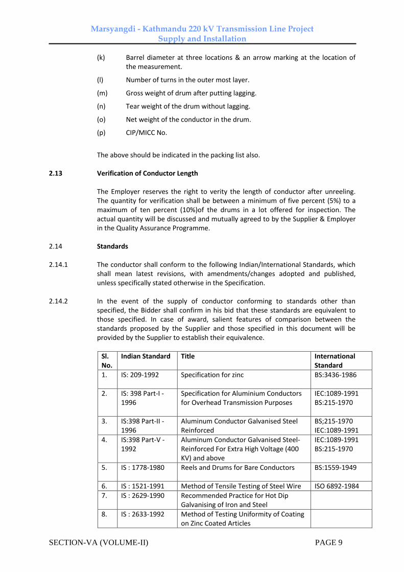
Marsyangdi - Kathmandu 220 kV Transmission Line Project Supply and Installation
SECTION-VA (VOLUME-II) PAGE 9
(k) Barrel diameter at three locations & an arrow marking at the location of the measurement.
(l) Number of turns in the outer most layer.
(m) Gross weight of drum after putting lagging.
(n) Tear weight of the drum without lagging.
(o) Net weight of the conductor in the drum.
(p) CIP/MICC No.
The above should be indicated in the packing list also. 2.13 Verification of Conductor Length The Employer reserves the right to verity the length of conductor after unreeling.
The quantity for verification shall be between a minimum of five percent (5%) to a maximum of ten percent (10%)of the drums in a lot offered for inspection. The actual quantity will be discussed and mutually agreed to by the Supplier & Employer in the Quality Assurance Programme.
2.14 Standards 2.14.1 The conductor shall conform to the following Indian/International Standards, which
shall mean latest revisions, with amendments/changes adopted and published, unless specifically stated otherwise in the Specification.
2.14.2 In the event of the supply of conductor conforming to standards other than
specified, the Bidder shall confirm in his bid that these standards are equivalent to those specified. In case of award, salient features of comparison between the standards proposed by the Supplier and those specified in this document will be provided by the Supplier to establish their equivalence.
Sl. No.
Indian Standard Title International Standard
1. IS: 209-1992 Specification for zinc BS:3436-1986
2. IS: 398 Part-I -1996
Specification for Aluminium Conductors for Overhead Transmission Purposes
IEC:1089-1991 BS:215-1970
3. IS:398 Part-II -1996
Aluminum Conductor Galvanised Steel Reinforced
BS;215-1970 IEC:1089-1991
4. IS:398 Part-V -1992
Aluminum Conductor Galvanised Steel- Reinforced For Extra High Voltage (400 KV) and above
IEC:1089-1991 BS:215-1970
5. IS : 1778-1980 Reels and Drums for Bare Conductors BS:1559-1949
6. IS : 1521-1991 Method of Tensile Testing of Steel Wire ISO 6892-1984
7. IS : 2629-1990 Recommended Practice for Hot Dip Galvanising of Iron and Steel
8. IS : 2633-1992 Method of Testing Uniformity of Coating on Zinc Coated Articles
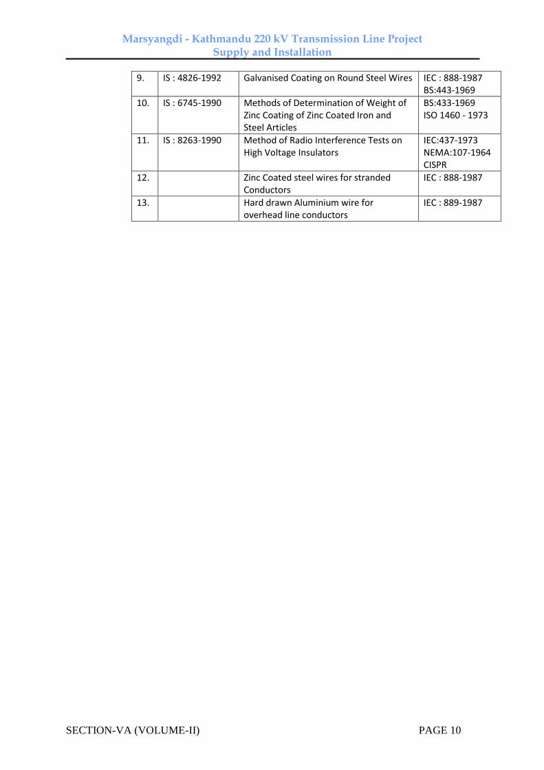
Marsyangdi - Kathmandu 220 kV Transmission Line Project Supply and Installation
SECTION-VA (VOLUME-II) PAGE 10
9. IS : 4826-1992 Galvanised Coating on Round Steel Wires IEC : 888-1987 BS:443-1969
10. IS : 6745-1990 Methods of Determination of Weight of Zinc Coating of Zinc Coated Iron and Steel Articles
BS:433-1969 ISO 1460 - 1973
11. IS : 8263-1990 Method of Radio Interference Tests on High Voltage Insulators
IEC:437-1973 NEMA:107-1964 CISPR
12. Zinc Coated steel wires for stranded Conductors
IEC : 888-1987
13. Hard drawn Aluminium wire for overhead line conductors
IEC : 889-1987
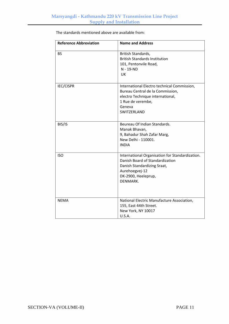
Marsyangdi - Kathmandu 220 kV Transmission Line Project Supply and Installation
SECTION-VA (VOLUME-II) PAGE 11
The standards mentioned above are available from:
Reference Abbreviation
Name and Address
BS British Standards, British Standards Institution 101, Pentonvile Road, N - 19-ND UK
IEC/CISPR International Electro technical Commission, Bureau Central de la Commission, electro Technique international, 1 Rue de verembe, Geneva SWITZERLAND
BIS/IS Beureau Of Indian Standards. Manak Bhavan, 9, Bahadur Shah Zafar Marg, New Delhi - 110001. INDIA
ISO International Organisation for Standardization. Danish Board of Standardization Danish Standardizing Sraat, Aurehoegvej-12 DK-2900, Heeleprup, DENMARK.
NEMA National Electric Manufacture Association, 155, East 44th Street. New York, NY 10017 U.S.A.
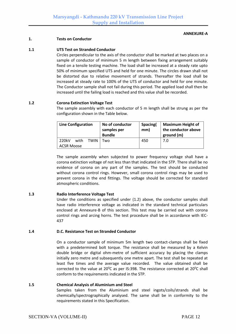
Marsyangdi - Kathmandu 220 kV Transmission Line Project Supply and Installation
SECTION-VA (VOLUME-II) PAGE 12
ANNEXURE-A 1. Tests on Conductor 1.1 UTS Test on Stranded Conductor Circles perpendicular to the axis of the conductor shall be marked at two places on a
sample of conductor of minimum 5 m length between fixing arrangement suitably fixed on a tensile testing machine. The load shall be increased at a steady rate upto 50% of minimum specified UTS and held for one minute. The circles drawn shall not be distorted due to relative movement of strands. Thereafter the load shall be increased at steady rate to 100% of the UTS of conductor and held for one minute. The Conductor sample shall not fail during this period. The applied load shall then be increased until the failing load is reached and this value shall be recorded.
1.2 Corona Extinction Voltage Test The sample assembly with each conductor of 5 m length shall be strung as per the
configuration shown in the Table below.
Line Configuration No of conductor samples per Bundle
Spacing(mm)
Maximum Height of the conductor above ground (m)
220kV with TWIN ACSR Moose
Two 450 7.0
The sample assembly when subjected to power frequency voltage shall have a
corona extinction voltage of not less than that indicated in the STP. There shall be no evidence of corona on any part of the samples. The test should be conducted without corona control rings. However, small corona control rings may be used to prevent corona in the end fittings. The voltage should be corrected for standard atmospheric conditions.
1.3 Radio Interference Voltage Test Under the conditions as specified under (1.2) above, the conductor samples shall
have radio interference voltage as indicated in the standard technical particulars enclosed at Annexure-B of this section. This test may be carried out with corona control rings and arcing horns. The test procedure shall be in accordance with IEC-437
1.4 D.C. Resistance Test on Stranded Conductor On a conductor sample of minimum 5m length two contact-clamps shall be fixed
with a predetermined bolt torque. The resistance shall be measured by a Kelvin double bridge or digital ohm-metre of sufficient accuracy by placing the clamps initially zero metre and subsequently one metre apart. The test shall be repeated at least five times and the average value recorded. The value obtained shall be corrected to the value at 200C as per IS:398. The resistance corrected at 200C shall conform to the requirements indicated in the STP.
1.5 Chemical Analysis of Aluminium and Steel Samples taken from the Aluminium and steel ingots/coils/strands shall be
chemically/spectrographically analysed. The same shall be in conformity to the requirements stated in this Specification.

Marsyangdi - Kathmandu 220 kV Transmission Line Project Supply and Installation
SECTION-VA (VOLUME-II) PAGE 13
1.6 Visual and Dimensional Check on Drums The drums shall be visually and dimensionally checked to ensure that they conform
to the requirements of this Specification. 1.7 Visual Check for Joints, Scratches etc. Conductor drums shall be rewound in the presence of the Employer. The Employer
shall visually check for scratches, joints etc. and that the conductor generally conform to the requirements of this Specification. Five percent (5%) to ten percent (10%) drums from each lot shall be rewound in the presence of the Employer's representative. The actual quantity will be discussed and mutually agreed to by the Supplier & Employer in the Quality Assurance Programme.
1.8 Dimensional Check on Steel and Aluminium Strands The individual strands shall be dimensionally checked to ensure that they conform to
the requirement of this Specification. 1.9 Check for Lay-ratios of Various Layers The lay-ratios of various layers shall be checked to ensure that they conform to the
requirements of this Specification. 1.10 Procedure Qualification test on welded Aluminium strands. Two Aluminium wire shall be welded as per the approved quality plan and shall be
subjected to tensile load. The breaking strength of the welded joint of the wire shall not be less than the breaking strength of individual strands.
1.11 Chemical Analysis of Zinc Samples taken from the zinc ingots shall be chemically/ spectrographically analyzed.
The same shall be in conformity to the requirements stated in the Specification. 1.12 Galvanizing Test The test procedure shall be as specified in IEC : 888. The material shall conform to
the requirements of this Specification. The adherence of zinc shall be checked by wrapping around a mandrel four times the diameter of steel wire.
1.13 Torsion and Elongation Tests on Steel Strands The test procedures shall be as per clause No. 10.3 of IEC : 888. In torsion test, the
number of complete twists before fracture shall not be less than that indicated in the STP. In case test sample length is less or more than 100 times the stranded diameter of the strand, the minimum number of twists will be proportioned to the length and if number comes in the fraction then it will be rounded off to next higher whole number. In elongation test, the elongation of the strand shall not be less than 4% for a gauge length of 250 mm.
1.14 Check on Barrel Batten strength of Drums The details regarding barrel batten strength test will be discussed and mutually
agreed to by the Supplier & Employer in the Quality Assurance Programme.

Marsyangdi - Kathmandu 220 kV Transmission Line Project Supply and Installation
SECTION-VA (VOLUME-II) PAGE 14
Annexure-B
STANDARD TECHNICAL PARTICULARS OF ACSR MOOSE CONDUCTOR
Sl. Description Unit Guaranteed Values
1.0 Raw Materials
1.1 Steel Wire / Rods
1.1 Aluminium
a) Minimum purity of Aluminium % 99.50
b) Maximum copper content % 0.04
1.2 Steel wires/ rods
a) Carbon % 0.50 to 0.85
b) Manganese % 0.50 to 1.10
c) Phosphorous % Not more than 0.035
d) Sulphur % Not more than 0.045
e) Silicon % 0.10 to 0.35 (Max.)
1.3 Zinc
a) Minimum purity of Zinc .% 99.95
2.0 Aluminum strands after stranding
2.1 Diameter
a) Nominal mm 3.53
b) Maximum mm 3.55
c) Minimum mm 3.51
2.2 Minimum breaking load of strand
a) Before stranding KN 1.57
b) After stranding KN 1.49
2.3 Maximum resistance of 1 m length of strand at 20 deg. C
Ohm 0.002921
3.0 Steel strand after stranding
2.1 Diameter
a) Nominal mm 3.53
b) Maximum mm 3.59
c) Minimum mm 3.47
3.2 Minimum breaking load of strand
a) Before stranding KN 12.63
b) After stranding KN 11.99

Marsyangdi - Kathmandu 220 kV Transmission Line Project Supply and Installation
SECTION-VA (VOLUME-II) PAGE 15
STANDARD TECHNICAL PARTICULARS OF ACSR MOOSE CONDUCTOR
Sl. Description Unit Guaranteed Values
3.3 Galvanising
a) Minimum weight of zinc coating per sq.m.
gm 250
b) Minimum number of dips that the galvanised strand can withstand in the standard preece test
Nos. 2 dips of one minute & 1 dip of half minute
c) Min. No. of twists in guage length equal 100 times the dia. of wire which the strand can withstand in the torsion test (after stranding)
Nos 16
4. Stranded Conductor
4.1 UTS of the conductor kN 161.20 (Min.)
4.2 Lay length of outer steel layer mm Max Min
a)
Outer Steel layer mm 18 16
b) 12 wire Aluminium layer mm 14 12
c) 18 wire Aluminium layer mm 13 11
d) 24 wire Alumimium Layer mm 12 10
4.3 DC resistance of the conductor at 20°C
ohm/km
0.05552
4.4 Minimum corona Extinction Voltage (line to Earth) under Dry condition
kV (rms) 320
4.5 RIV at 1 Mhz at 305 kv (line to earth) under Dry condition
Micto Volts
Below 1000
4.6 Standard length of the conductor m 1800
4.7 Tolerance on Standard length % (+/-) 5
4.8 Direction of lay of outer layer Right Hand
4.9 Linear mass of the conductor
a) Standard kg/km 2004
b) Minimum kg/km 1969
c) Maximum kg/km 2040

Marsyangdi - Kathmandu 220 kV Transmission Line Project Supply and Installation
SECTION-VA (VOLUME-II) PAGE 16

Marsyangdi - Kathmandu 220 kV Transmission Line Project Supply and Installation
SECTION–VI
Volume-II Doc. No. CC-Consultancy-NEA-M-K-2015 1
TECHNICAL SPECIFICATIONS
SECTION - 6
1.0 Technical Description of Galvanised Steel Earth wire
1.1 Details of Earth wire
1.11 The galvanised steel earth wire shall generally conform to the specification of ACSR core wire as mentioned in IS: 398 (Part-II)-1976 except where otherwise specified herein.
1.1.2 The details of the earth wire for 220 kV are tabulated below:
a) Stranding and wire : 7/3.35 mm steel diameter
b) Number of strands
Steel core : 1
Outer steel layer : 6
c) Total sectional area : 61.7 sqmm.
Other technical details are furnished in the section–I of this Specification.
1.2 Workmanship
1.2.1 All steel strands shall be smooth, uniform and free from all imperfections, such as
spills and splits, die marks, scratches, abrasions and kinks after drawing and also
after stranding.
1.2.2 The finished material shall have minimum brittleness as it will be subjected to
appreciable vibration while in use.
1.2.3 The steel strands shall be hot dip qalvanised and shall have minimum Zinc
coating after stranding, as stipulated in Cl. 2.0 of this section of the Specification.
The zinc coating shall be smooth, continuous, of uniform thickness, free from
imperfections. The steel wire rod shall be of such quality and purity that, when
drawn to the size of the strands specified and coated with zinc, the finished
strands shall be of uniform quality and have the same properties and
characteristics as prescribed in ASTM designation B498-M.
1.2.4 The steel strands shall be preformed and post formed in order to prevent
spreading of strands while cutting of composite earth wire. Care shall be taken to
avoid damage to galvanisation during preforming and postforming operation.
1.2.5 To avoid susceptibility towards wet storage stains (white rust), the finished
material shall be provided with a protective coating of boiled linseed oil.

Marsyangdi - Kathmandu 220 kV Transmission Line Project Supply and Installation
SECTION–VI
Volume-II Doc. No. CC-Consultancy-NEA-M-K-2015 2
1.3 Joints in Wires
There shall be no joint of any kind in the finished steel wire strand entering into
the manufacture of the earth wire. There shall be no strand joints or strand splices
in any length of the completed stranded earth wire.
1.4 Tolerances
The manufacturing tolerance to the extent of the limits as stipulated in Clause 2.0,
Table 1 of this section of the Specification only shall be permitted in the diameter
of the individual steel strands and lay length of the earth wire:
1.5 Materials
1.5.1 Steel
The steel wire strands shall be drawn from high carbon steel rods and the
chemical composition shall conform to the requirements as stipulated in Clause
2.0, Table 1 of this section of the Specification.
1.5.2 Zinc
The zinc used for galvanising shall be electrolytic High Grade Zinc and shall
conform to the requirements of IS 209.
1.6 Standard Length
1.6.1 The standard length of the earth wire shall be as stipulated in Clause 2.0, Table 1
with the specified tolerance on standard length.
1.6.2 Random length will be accepted provided no length is less than 70% of standard
length and the total quantity of random lengths is not more than ten (10) percent
of the total quantity in each shipment.
2.0 Standard Technical Particulars
2.1 The standard Technical Particulars to be adhered by the contractor/ manufacturer
are furnished in Annexure-B if this section.
3.0 Tests and Standards
3.1 Type Tests on Earthwire
3.1.1 The required type tests on earthwire are stipulated hereunder. The specified type
tests under the following clause shall not be required to be carried out if a valid
test certificate is available for the same earthwire. The tests certificate shall be
considered valid if:

Marsyangdi - Kathmandu 220 kV Transmission Line Project Supply and Installation
SECTION–VI
Volume-II Doc. No. CC-Consultancy-NEA-M-K-2015 3
i. Tests conducted earlier is either conducted in accredited laboratory
(accredited based on ISO/IEC vide 25/17025 or EN 45001 by the National
accreditation body of the country where laboratory is located) or witnessed by the
representative(s) of any utility and
ii. Tests have been conducted not prior to 5 (five) years from the date of bid
opening.
In case the test have been conducted earlier than the above stipulated period or in
the event of any discrepancy in the test report (i.e., any test not applicable due to
any design/manufacturing change including substitution of components or due to
non-compliance with the requirement stipulated in the Technical Specifications),
the tests shall be conducted by the Supplier at no extra cost to the Purchaser.
3.1.2 The following tests are required on samples of earthwire from each
manufacturing works:-
a) UTS test : As per Annexure - A
b) DC resistance test : As per Annexure - A
3.2 Acceptance Tests on Earthwire
a) Visual and dimensional check on
drum
: As per Annexure - A
b) Visual check for joints scratches etc.
and lengths of earthwire
: As per Annexure - A
c) Dimensional check : As per Annexure - A
d) Lay length check : As per Annexure - A
e) Galvanising test : As per Annexure - A
f) Torsion test : As per Annexure - A
g) Elongation test : As per IS:398 (Part-II)
h) Wrap test : As per IS:398 (Part-II)
i) DC resistance test : As per IS:398 (Part-II)
j) Breaking load test : As per IS:398 (Part-II)
k) Chemical Analysis of steel : As per Annexure - A

Marsyangdi - Kathmandu 220 kV Transmission Line Project Supply and Installation
SECTION–VI
Volume-II Doc. No. CC-Consultancy-NEA-M-K-2015 4
3.3 Routine Tests on Earthwire
a) Check for correctness of stranding : As per Annexure - A
b) Check that there are no cuts, fins etc.
on the strands.
: As per Annexure - A
c) Check that drums are as per
Specification.
: As per Annexure - A
3.4 Tests During Manufacture Earthwire
a) Chemical analysis of zinc used for
galvanising
: As per Annexure - A
b) Chemical analysis of steel : As per Annexure - A
3.5 Testing Expenses
3.5.1 No type test charges shall be payable to the supplier.
3.5.2 Bidders shall indicate the laboratories in which they propose to conduct the
type tests. They shall ensure that the tests can be completed in these
laboratories within the time schedule guaranteed by them.
3.5.3 In case of failure in any type test the Contractor is either required to
manufacture fresh sample lot and repeat all the test successfully once or
repeat that particular type test three times successfully on the sample selected
from the already manufactured lot at his own expenses. In case fresh lot is
manufactured for testing then the lot already manufactured shall be rejected.
The decision of the Purchaser in this regard shall be final and binding on
Contractor.
3.5.4 The entire cost of testing for the acceptance and routine tests and tests during
manufacture specified herein shall be treated as included in the quoted unit
price except for the expenses of the inspector/ Employer’s representative.
3.5.5 In case of failure in any type test, repeat type tests are required to be
conducted, then all the expenses for deputation of Inspector/ Employer's
representative shall be deducted from the contract price. Also if on receipt of
the Contract's notice of testing the Employer's representative/Inspector does
not find ‘materials and facilities’ to be ready for testing, the expenses incurred
by the Employer for re-deputation shall be deducted from the contract price.

Marsyangdi - Kathmandu 220 kV Transmission Line Project Supply and Installation
SECTION–VI
Volume-II Doc. No. CC-Consultancy-NEA-M-K-2015 5
3.6 Additional Tests
3.6.1 The Owner reserves the right of having at his own expenses any other test(s)
of reasonable nature carried out at Contractor’s premises, at site, or in any
other place in addition to the aforesaid type, acceptance and routine tests to
satisfy himself that the materials comply with the Specifications.
3.6.2 The Owner also reserves the right to conduct all the tests mentioned in this
specification at his own expense on the samples drawn from the site at
Contractor’s premises or at any other test center. In case of evidence of non
compliance, it shall be binding on the part of Contractor to prove the
compliance of the items to the technical specifications by repeat tests, or
correction of deficiencies, or replacement of defective item all without any
extra cost to the Owner.
3.7 Sample Batch for Type Testing
3.7.1 The Contractor shall offer material for selection of samples for type testing
only after getting Quality Assurance Plan approved from Owner’s Quality
Assurance Deptt. The sample shall be manufactured strictly in accordance
with the Quality Assurance Plan approved by Owner.
3.7.2 The Contractor shall offer at least three drums for selection of sample required
for conducting all the type test.
3.7.3 The Contractor is required to carry out all the Acceptance tests successfully in
presence of Owner’s representative before sample selection.
3.8 Test Reports
3.8.1 Copies of type test reports shall be furnished in at least six copies along with
one original. One copy will be returned duly certified by the Owner only after
which the commercial production of the material shall start.
3.8.2 Record of routine test reports shall be maintained by the Contractor at his
works for periodic inspection by the Owner's representative.
3.8.3 Test Certificates of tests during manufacture shall be maintained by the
Contractor. These shall be produced for verification as and when desired by
the Owner.
3.9 Inspection
3.9.1 The Owner 's representative shall at all times be entitled to have access to the
works and all places of manufacture, where earth wire shall be manufactured
and representative shall have full facilities for unrestricted inspection of the
Contractor’s works, raw materials and process of manufacture for conducting
necessary tests as detailed herein.

Marsyangdi - Kathmandu 220 kV Transmission Line Project Supply and Installation
SECTION–VI
Volume-II Doc. No. CC-Consultancy-NEA-M-K-2015 6
3.9.2 The Contractor shall keep the Owner informed in advance of the time of
starting and of the progress of manufacture of earth wire in its various stages
so that arrangements can be made for inspection.
3.9.3 No material shall be dispatched from its point of manufacture before it has
been satisfactorily inspected and tested, unless the inspection is waived off by
the Owner in writing. In the latter case also the earth wire shall be dispatched
only after satisfactory testing for all tests specified herein have been
completed.
3.9.4 The acceptance of any quantity of material shall in no way relieve the
Contractor of any of his responsibilities for meeting all requirements of the
Specification, and shall not prevent subsequent rejection if such material is
later found to be defective.
3.10 Test Facilities
3.10.1 The following additional test facilities shall be available at the Contractor’s
works :
a) Calibration of various testing and measuring equipment including
tensile testing machine, resistance measurement facilities, burette,
thermometer, barometer etc.
b) Standard resistance for calibration of resistance bridges.
c) Finished Earth wire shall be checked for length verification and
surface finish on separate rewinding machine at reduced speed
(variable from 8 to 16 meters per minute). The rewinding facilities
shall have appropriate clutch system and free of vibrations, jerks etc.,
with traverse laying facilities.
3.11 Packing for Earth wire
3.11.1 The Earth wire shall be supplied in non-returnable, strong, wooden drums
and provided with lagging of adequate strength, constructed to protect the
Earth wire against all damage and displacement during transit, storage and
subsequent handling and stringing operations in the field. The Contractor
shall be responsible for any loss or damage during transportation handling
and storage due to improper packing. The drums shall generally conform to
IS 778-1980, except as otherwise specified hereinafter.
3.11.2 The drums shall be suitable for wheel mounting and for letting off the earth
wire under a minimum controlled tension of the order of 5 kN
Marsyangdi - Kathmandu 220 kV Transmission Line Project Supply and Installation
SECTION–VI
Volume-II Doc. No. CC-Consultancy-NEA-M-K-2015 7
3.11.3 The general outline of the drum for Earth wire shall be as per annexed
drawing. The Contractor should submit their proposed drum drawings along
with the bid.
3.11.4 For Earth wire, two standard lengths shall be wound on each drum.
3.11.5 For Earth wire, each strand shall be individually welded to prevent parting of
two lengths at a tension less than 15 kN. The two ends where the first length
finishes and the second length starts, shall be clearly marked with adhesive
tape and no weld should be present outside these marks. The length between
the two marks shall be treated as scrap and will not be taken into account for
measurement purposes.
3.11.6 All wooden components shall be manufactured out of seasoned softwood free
from defects that may materially weaken the component parts of the drums.
Preservative treatment shall be applied to the entire drum with preservatives
of a quality which is not harmful to the earth wire.
3.11.7 The flanges shall be of two ply construction with each ply at right angles to
the adjacent ply and nailed together. The nails shall be driven from the inside
face flange, punched and then clenched on the outer face. The thickness of
each ply shall not vary by more than 3 mm from that indicated in the figure.
There shall be at least 3 nails per plank of ply with maximum nail spacing of
75 mm. Where a slot is cut in the flange to receive the inner end of the earth
wire the entrance shall be in line with the periphery of the barrel.
3.11.8 The wooden battens used for making the barrel of the earth wire shall be of
segmental type. These shall be nailed to the barrel supports with at least two
nails. The battens shall be closely butted and shall provide a round barrel with
smooth external surface. The edges of the battens shall be rounded or
chamfered to avoid damage to the earth wire.
3.11.9 Barrel studs shall be used for the construction of drums. The flanges shall be
holed and the barrel studs shaft be threaded over a length on either end,
sufficient to accommodate washers, spindle plates and nuts for fixing flanges
at the required spacing.
3.11.10 Normally, the nuts on the studs shall stand protruded of the flanges. All the
nails used on the inner surface of the flanges and the drum barrel shall be
counter sunk. The ends of barrel shall generally be flushed with the top of the
nuts.
3.11.11 The inner cheek of the flanges and drum barrel surface shall be painted with a
bitumen based paint.
Marsyangdi - Kathmandu 220 kV Transmission Line Project Supply and Installation
SECTION–VI
Volume-II Doc. No. CC-Consultancy-NEA-M-K-2015 8
3.11.12 Before reeling, cardboard or double corrugated or thick bituminous
waterproof bamboo paper shall be secured to the drum barrel and inside of
flanges of the drum by means of a suitable commercial adhesive material.
After reeling the earth wire, the exposed surface of the outer layer of earth
wire shall be wrapped with water proof thick bituminous bamboo paper to
preserve the earth wire from dirt, grit and damage during transport and
handling.
Medium grade craft/crepe/polythene paper shall be used in between the
layers.
3.11.13 A minimum space of 50 mm for earth wire shall be provided between the
inner surface of the external protective lagging and outer layer of the earth
wire.
3.11.14 Each batten shall be securely nailed across grains as far as possible to the
flange, edges with at least 2 nails per end. The length of the nails shall not be
less than twice the thickness of the battens. The nails shall not protrude above
the general surface and shall not have exposed sharp edges or allow the
battens to be released due to corrosion.
3.11.15 The nuts on the barrel studs shall be tack welded on the one side in order to
fully secure them. On the second end, a spring washer shall be used.
3.11.16 Outside the protective lagging there shall be minimum of two binder
consisting of hoop iron/galvanised steel wire. Each protective lagging shall
have two recesses to accommodate the binders.
3.11.17 The earth wire ends shall be properly sealed and secured on the side of one of
the flanges to avoid loosening of the earth wire layers during transit and
handling.
3.12 Marking
Each drum shall have the following information stenciled on it in indelible ink
along with other essential data
(a) Contract/Award letter number.
(b) Name and address of consignee.
(c) Manufacturer’s name and address.
(d) Drum number
(e) Size of earth wire
(f) Length of earth wire in meters

Marsyangdi - Kathmandu 220 kV Transmission Line Project Supply and Installation
SECTION–VI
Volume-II Doc. No. CC-Consultancy-NEA-M-K-2015 9
(g) Gross weight of drum with earth wire & lagging
(h) Weight of empty drum with lagging
(i) Arrow marking for unwinding
(j) Position of the earth wire ends
(k) Number of turns in the outer most layer
(l) Distance between outer most layer of Earth wire and the inner surface
of lagging
(n) Barrel diameter at three locations and an arrow marking at the location
of measurement
3.13 Verification of Earth wire Length
The Owner reserves the right to verify the length of earth wire after unreeling
atlest ten (10) percent of the drums in a lot offered for inspection.
3.14 Standards
The earth wire shall conform to the following Indian/ International Standards,
which shall mean latest revisions, amendments/changes adopted and
published, unless otherwise in the Specification.
In the event of the supply of earth wire conforming to standards other than
specified, the Contractor shall confirm in his bid that these standards are
equivalent to those specified. In case of award salient features of comparison
between the standards proposed by the Contractor and those specified in
this documents will be provided by the Contractor to establish their
equivalence.
Sl.
No.
Indian
Standard
Title International
Standard
1. IS: 209-1992 Specification for zinc BS:3436-1986
2. IS: 398-1990 Specification for Aluminium Conductors
for Overhead Transmission Purposes
IEC:1089-1991
BS:215-1970
3. IS:398-1998
Part-II
Aluminum Conductor Galvanised Steel
Reinforced
BS;215-1970
IEC:1089-1991
4. IS :398-1996
Part-IV
Aluminum Alloy stranded conductor
BS-3242-1970
ASTM-8399 M86
IEC:1089-1991
5. IS:398-1992 Aluminum Conductor Galvanised Steel- IEC:1089-1991

Marsyangdi - Kathmandu 220 kV Transmission Line Project Supply and Installation
SECTION–VI
Volume-II Doc. No. CC-Consultancy-NEA-M-K-2015 10
Part-V Reinforced For Extra High Voltage (400
KV) and above
BS:215-1970
6. IS : 1778-
1997
Reels and Drums for Bare Conductors BS:1559-1949
7. IS : 1521-
1991
Method of Tensile Testing of Steel Wire ISO 6892-1984
8. IS : 2629-
1990
Recommended Practice for Hot Dip
Galvanising of Iron and Steel
9. IS : 2633-
1992
Method of Testing Uniformity of Coating
on Zinc Coated Articles
10. IS : 4826-
1992
Galvanised Coating on Round Steel
Wires
IEC : 888-1987
BS:443-1969
11. IS : 6745-
1991
Methods of Determination of Weight of
Zinc Coating of Zinc Coated Iron and
Steel Articles
BS:433-1969
ISO 1460 - 1973
12. IS : 8263-
1991
Method of Radio Interference Tests on
High Voltage Insulators
IEC:437-1973
NEMA:107-1964
CISPR
13. IS : 9997-
1991
Aluminium Alloy Redraw Rods IEC 104 - 1987
14. Zinc Coated steel wires for stranded
Conductors
IEC : 888-1987
15. Hard drawn Aluminium wire for
overhead line conductors
IEC : 889-1987

Marsyangdi - Kathmandu 220 kV Transmission Line Project Supply and Installation
SECTION–VI
Volume-II Doc. No. CC-Consultancy-NEA-M-K-2015 11
The standards mentioned above are available from:
Reference Abbreviation
Name and Address
BS British Standards,
British Standards Institution
101, Pentonvile Road,
N - 19-ND
UK
IEC/CISPR International Electro technical Commission,
Bureau Central de la Commission,
electro Technique international,
1 Rue de verembe,
Geneva
SWITZERLAND
BIS/IS Beureau Of Indian Standards.
Manak Bhavan,
9, Bahadur Shah Zafar Marg,
New Delhi - 110001.
INDIA
ISO International Organisation for
Standardization.
Danish Board of Standardization
Danish Standardizing Sraat,
Aurehoegvej-12
DK-2900, Heeleprup,
DENMARK.
NEMA National Electric Manufacture Association,
155, East 44th Street.
New York, NY 10017
U.S.A.

Marsyangdi - Kathmandu 220 kV Transmission Line Project Supply and Installation
SECTION–VI
Volume-II Doc. No. CC-Consultancy-NEA-M-K-2015 12
ANEXURE-A
1.0 Tests on Earth wire
1.1 UTS Test
Circles perpendicular to the axis of the earth wire shall be marked at two
places on a sample of earth wire of minimum 5 m length suitably compressed
with dead end clamps at either end. The load shall be increased at a steady
rate up to 50% of UTS and held for one minute. The circles drawn shall not be
distorted due to relative movement of strands. Thereafter the load shall be
increased at steady rate to 100% of UTS and held for one minute. The earth
wire sample shall not fail during this period. The applied load shall then be
increased until the failing load is reached and the value recorded.
1.2 D.C. Resistance Test
On a earth wire sample of minimum 5m length two contact clamps shall be
fixed with a predetermined bolt torque. The resistance shall be measured by a
Kelvin double bridge by placing the clamps initially at zero meter and
subsequently one meter apart. The test shall be repeated at least five times
and the average value recorded. The value obtained shall be corrected to the
value at 200C. The resistance corrected at 200C shall conform to the
requirements of this Specification.
1.3 Chemical Analysis of Zinc
Samples taken from the zinc ingots shall be chemically/ spectrographically
analysed. The same shall be in conformity to the requirements stated in the
Specification.
1.4 Chemical Analysis of Steel
Samples taken from the steel ingots/coils/strands shall be
chemically/spectrographically analysed. The same shall be in conformity to
the requirements stated in this Specification.
1.5 Visual and Dimensional Check on Drums and its barrel strength test.
The drums shall be visually and dimensionally checked to ensure that they
conform to the requirements of this Specification. The details regarding barrel
strength test will be discussed and mutually agreed to by Contractor and
Owner in the quality assurance programme.

Marsyangdi - Kathmandu 220 kV Transmission Line Project Supply and Installation
SECTION–VI
Volume-II Doc. No. CC-Consultancy-NEA-M-K-2015 13
1.6 Visual Check for Joints, Scratches etc. and Length of Earth wire
Ten percent drums from each lot shall be rewound in the presence of the
Owner. The Owner shall visually check for scratches, joints etc. and see that
the earth wire generally conforms to the requirements of this Specification.
The length of earth wire wound on the drum shall be measured with the help
of counter meter during rewinding.
1.7 Dimensional Check
The individual strands shall be dimensionally checked to ensure that they
conform to the requirement of this Specification.
1.8 Lay Length Check
The lay length shall be checked to ensure that they conform to the
requirements of this Specification.
1.9 Galvanising Test
The test procedure shall be as specified in IS 4826-1979. The material shall
conform to the requirements of this Specification. The adherence of zinc shall
be checked by wrapping around a mandrel four times the diameter of steel
wire.
1.10 Torsion Test
The minimum number of twists which a single steel strand shall withstand
during torsion test shall be eighteen for a length equal to 100 times the
standard diameter of the strand. In case test sample length is less or more
than 100 times the stranded diameter of the strand the minimum number of
twists will be proportioned to the length and if number comes in the fraction
then it will be rounded off to next higher whole number.
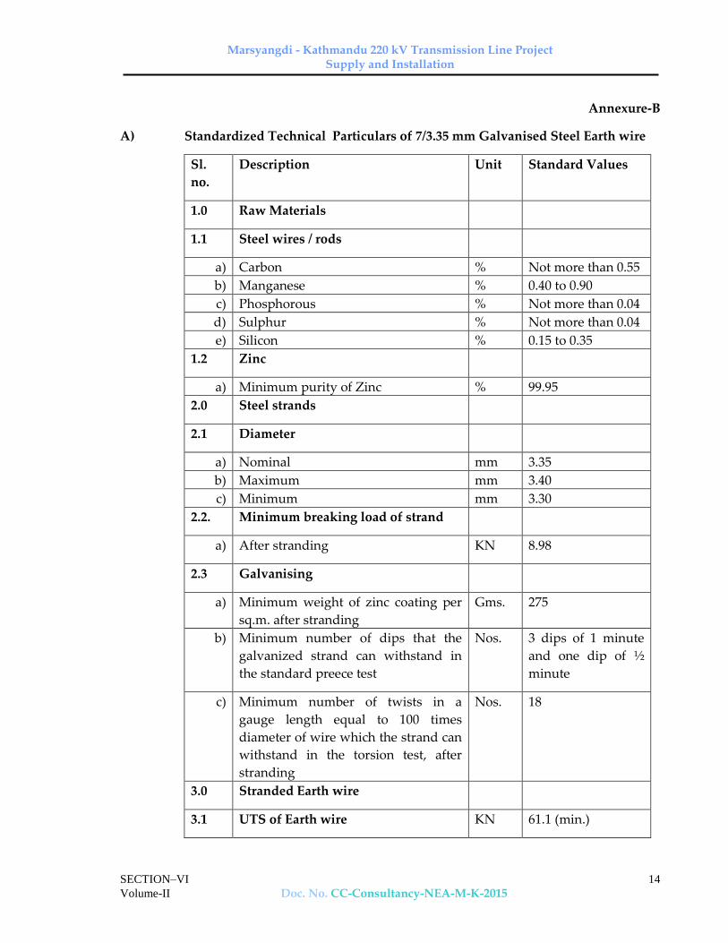
Marsyangdi - Kathmandu 220 kV Transmission Line Project Supply and Installation
SECTION–VI
Volume-II Doc. No. CC-Consultancy-NEA-M-K-2015 14
Annexure-B
A) Standardized Technical Particulars of 7/3.35 mm Galvanised Steel Earth wire
Sl.
no.
Description Unit Standard Values
1.0 Raw Materials
1.1 Steel wires / rods
a) Carbon % Not more than 0.55
b) Manganese % 0.40 to 0.90
c) Phosphorous % Not more than 0.04
d) Sulphur % Not more than 0.04
e) Silicon % 0.15 to 0.35
1.2 Zinc
a) Minimum purity of Zinc % 99.95
2.0 Steel strands
2.1 Diameter
a) Nominal mm 3.35
b) Maximum mm 3.40
c) Minimum mm 3.30
2.2. Minimum breaking load of strand
a) After stranding KN 8.98
2.3 Galvanising
a) Minimum weight of zinc coating per
sq.m. after stranding
Gms. 275
b) Minimum number of dips that the
galvanized strand can withstand in
the standard preece test
Nos. 3 dips of 1 minute
and one dip of ½
minute
c) Minimum number of twists in a
gauge length equal to 100 times
diameter of wire which the strand can
withstand in the torsion test, after
stranding
Nos. 18
3.0 Stranded Earth wire
3.1 UTS of Earth wire KN 61.1 (min.)

Marsyangdi - Kathmandu 220 kV Transmission Line Project Supply and Installation
SECTION–VI
Volume-II Doc. No. CC-Consultancy-NEA-M-K-2015 15
Sl.
no.
Description Unit Standard Values
3.2 Lay length of outer steel layer
a) Standard mm 181
b) Maximum mm 198
c) Minimum mm 165
3.3 Maximum DC resistance of earth
wire at 200 C
Ohm/
km
2.5
3.4 Standard length of earth wire M 2000
3.5 Tolerance on standard length % ±5
3.6 Direction of lay for outside layer Right hand
3.7 Linear mass
a) Standard Kg/km 482
b) Maximum Kg/km 496
c) Minimum Kg/km 468

Marsyangdi - Kathmandu 220 kV Transmission Line Project Supply and Installation
SECTION-VII A(TS)
VOLUME- Doc. No : CC-Consultancy-NEA-M-K-2015 1
SECTION-VIIA
INSULATOR
Marsyangdi - Kathmandu 220 kV Transmission Line Project Supply and Installation
SECTION-VII A(TS)
VOLUME- Doc. No : CC-Consultancy-NEA-M-K-2015 2
SECTION-VII A
CONTENTS
—————————————————————————————————————————
Clause Description Page No.
—————————————————————————————————————————
1. Technical Description of Disc Insulators 1
2. Equipment Marking 5
3. Bid Drawings 5
4. Test and Standards 6
Annexure-A 15 —————————————————————————————————————————

Marsyangdi - Kathmandu 220 kV Transmission Line Project Supply and Installation
SECTION-VII A(TS)
VOLUME- Doc. No : CC-Consultancy-NEA-M-K-2015 3
TECHNICAL SPECIFICATIONS
SECTION –VII A
1.0 Technical Description of Disc Insulators
1.1 Details of Disc Insulators
1.1.1 The Insulator strings shall consist of Standard discs for a three phase, 50 Hz, effectively earthed 220 kV transmission system in a lightly polluted atmosphere. The discs shall be cap and pin, ball and socket type.
1.1.2 Supplier may quote for disc insulator, made of either electro-porcelain or
toughened glass. 1.1.3 The size of disc insulator, minimum creepage distance, the number to be
used in different type of strings, their electromechanical strength and mechanical strength of insulator string along with hardware fittings shall be as follows:
Sl.
No
Type of
string
Size of
disc
insulators
(mm)
Minimum
creepage
distance
of each
disc (mm)
No. of
discs
Electro-
mechnical
strength
of
insulator
disc (kN)
Mechanical
strength of
insulator
string along
with
hardware
fittings (kN)
1. Single “I”
suspension
Pilot
255x145 or
280x145
315 1×16 120 120
2. Double
Tension
String
280 x 170 315 2 x 17 160 2 x 160
3. Triple
Tension
String
280 x 170 315 3 x 17 160 3 x 160
1.2 Pin and Cap
1.2.1 Pin and Cap shall be designed to transmit the mechanical stresses to the shell
by compression and develop uniform mechanical strength in the insulator. The cap shall be circular with the inner and outer surfaces concentric, of such design that it will not yield or distort under load conditions.
1.2.2 The pin ball shall move freely in the cap socket but without danger of accidental uncoupling during erection or in position. The design of the disc

Marsyangdi - Kathmandu 220 kV Transmission Line Project Supply and Installation
SECTION-VII A(TS)
VOLUME- Doc. No : CC-Consultancy-NEA-M-K-2015 4
should be such that stresses due to expansion or contraction in any part of the insulator shall not lead to deterioration.
1.3 Security clip
1.3.1 Security clip for use with ball and socket coupling shall be of R-shaped hump type which shall provide positive locking of the coupling as per IS:2486-(Part-Ill)/IEC : 372. The legs of the security clips shall be spread after installation to prevent complete withdrawal from the socket. The locking device should be resilient, corrosion resistant and of suitable mechanical strength. There shall be no risk of the locking device being displaced accidentally or being rotated when in position. Under no circumstances shall locking device allow separation of insulator units or fittings.
1.3.2 The hole for the security clip shall be countersunk and the clip shall be of such design that the eye of clip may be engaged by a hot line clip puller to provide for disengagement under energised conditions. The force required to pull the security clip into its unlocked position shall not be less than 50N (5 kg) or more than 500N (50 kg).
1.4 Ball and Socket Designation
The dimensions of the balls and sockets shall be 20 mm designation for 120 and 160 kN disc insulator in accordance with the standard dimensions stated in IS:2486 - (Part - II)/ IEC:120.
1.5 Dimensional Tolerance of Insulator Disc (Standard)
It shall be ensured that the dimensions of the disc insulators are within the
limits specified below :
a) Diameter of Disc (mm)
Standard Maximum Minimum
120 kN Disc 255/280
266/293
244/267
160 kN Disc
280
293
267
b) Ball to ball spacing between discs (mm)
Standard Maximum Minimum
120 kN Disc
145
149
141
160 kN Disc
170
175
163
1.6 Interchangeability

Marsyangdi - Kathmandu 220 kV Transmission Line Project Supply and Installation
SECTION-VII A(TS)
VOLUME- Doc. No : CC-Consultancy-NEA-M-K-2015 5
The disc insulators inclusive of the ball and socket fittings shall be of standard
design suitable for use with the hardware fittings of any make conforming to
relevant Indian/International Standards.
1.7 Corona and RI Performance
All surfaces must be clean, smooth, without cuts, abrasions or projections. No part shall be subjected to excessive localised pressure. The metal parts shall be so designed and manufactured that it shall not generate any Radio Interference beyond specified limit and not produce any noise generating corona under the operating conditions.
1.8 Maintenance
1.8.1 The disc insulators offered shall be suitable for employment of hot line maintenance techniques so that the usual hot line operations can be carried out with ease, speed and safety.
1.8.2 Bidders shall indicate the methods generally used in the routine hot and dead line maintenance of EHV Lines for which similar disc insulators have been supplied by them. Bidders shall also indicate the recommended periodicity of such maintenance.
1.9 Materials
1.9.1 Porcelain
The porcelain used in the manufacture of shells shall be sound, free from defects thoroughly vitrified and smoothly glazed. The porcelain used shall be non-porous of high dielectric, mechanical and thermal strength, free from internal stress blisters, laminations, voids, foreign matter, imperfections or other defects which might make it any way unsuitable for insulator shells. Porcelain shall remain unaffected by climatic conditions, ozone, acid, alkalies, zinc or dust.
1.9.2 Glaze
The finished porcelain shall be glazed in brown colour. The glaze shall cover all exposed parts of the insulator and shall have a good lusture, smooth surface and good performance under the extreme weather conditions of a tropical climate. It shall not crack or chip by ageing under the normal service conditions. The glaze shall have the same coefficient of expansion as of the porcelain body throughout the working temperature range.
1.9.3 Toughened Glass
The glass used for the shells shall be sound, free from defects such as flaws, bubbles, inclusions etc. and be of uniform toughness over its entire surface. All exposed glass surfaces shall be smooth.
1.9.4 Cement

Marsyangdi - Kathmandu 220 kV Transmission Line Project Supply and Installation
SECTION-VII A(TS)
VOLUME- Doc. No : CC-Consultancy-NEA-M-K-2015 6
Cement used in the manufacture of the insulator shall not cause fracture by expansion or loosening by contraction. The cement shall not give rise to chemical reaction with metal fittings and its thickness shall be as small and uniform as possible. Proper care shall be taken to correctly centre and locate individual parts during cementing.
1.9.5 Pins and Caps
Pins and Caps shall be made of drop forged steel and malleable cast iron/spheriodal graphite iron/drop forges steel respectively, duly hot dip galvanised and shall not be made by jointing, welding, shrink fitting or any other process from more than one piece of material.
1.9.6 Security Clips
Security clips shall be made of good quality stainless steel or phosphor bronze as per IS: 1385/IEC 60372. 2.5% extra security clip shall be provided.
1.10 Workmanship
1.10.1 All the material shall be of the latest design and conform to the best modern practices adopted in the extra high voltage field. Suppliers shall offer only such insulators as are guaranteed by him to be satisfactory and suitable for 220 kV Transmission lines and will give continued good service.
1.10.2 The design, manufacturing process and material control at various stages shall be such as to give maximum working load, highest mobility, best resistance to corrosion, good finish and elimination of sharp edges and corners to limit corona and radio interference.
1.10.3 The design of the insulators shall be such that stresses due to expansion and contraction in any part of the insulator shall not lead to deterioration.
1.10.4 Metal caps shall be free from cracks, seams, shrinks, air holes, burrs and rough edges. All surfaces of the metal parts shall be perfectly smooth with no projecting points or irregularities which may cause corona. All load bearing surfaces shall be smooth and uniform so as to distribute the loading stresses uniformly.
1.10.5 All ferrous parts shall be hot dip galvanised to give a minimum average coating of Zinc equivalent to 600 gm/sq.m. and shall be in accordance with the requirement of IS:2629/ISO-1461(E) and shall satisfy the tests mentioned in IS:2633 or equivalent international standard . The zinc used for galvanising shall be of Grade Zn 99.95 as per IS:209/BS 3436. The zinc coating shall be uniform, adherent, smooth, reasonably bright, continuous and free from imperfections such as flux, ash, rust stains, bulky white deposits and blisters. The galvanised metal parts shall be guaranteed to withstand atleast six successive dips each lasting for one (1) minute duration under the standard preece test.

Marsyangdi - Kathmandu 220 kV Transmission Line Project Supply and Installation
SECTION-VII A(TS)
VOLUME- Doc. No : CC-Consultancy-NEA-M-K-2015 7
1.10.6 Before ball fittings are galvanised, all die flashing on the shank surface of the ball shall be carefully removed without reducing the dimensions below the design requirements.
1.10.7 The design of the insulators shall be such that the shell shall not engage directly with hard metal. The design shall also be such that when units are coupled together there is no contact between the shell of one unit and metal of the next adjacent unit. The design of the shell ribs shall be such that the security clip of the insulator can be engaged and disengaged easily with hot stick without damaging the shell ribs.
1.10.8 Insulator units after assembly shall be concentric and co-axial within limits as permitted by the relevant Indian Standards.
1.10.9 The manufacturer of the insulators shall guarantee an insulator failure rate not exceeding 1 (one) per 10000 (ten thousand) per year for disc insulator per year. In case the annual failure rate during the first ten years of service exceeds the above figure, under normal operating condition, as will be determined by check to be conducted as per mutually agreed procedure and conditions upto ten years, (as permitted by the operating situation), the Supplier shall supply to the Employer free of cost spare insulators equal to 10 time the excess failure.
1.10.10 The Supplier shall guarantee that there shall not be any decapping/breaking of insulators on line under normal operating conditions. In the event of any decapping/breaking and subsequent line drop, during the first ten years of service the Supplier shall have to pay NPRs. 1,00,000/- (NPRs. One hundred thousand only) per dropped string towards expenditure to be incurred by MEW for this line repair.
2.0 Equipment Marking
2.1 Each insulator disc shall be legibly and indelibly marked with the trade mark of the manufacturer, name of MEW and month & year of manufacture. The guaranteed combined mechanical and electrical strength shall be indicated in kilo Newton followed by the word ‘kN’ to facilitate easy identification and to ensure proper use.
2.2 For porcelain insulator, the marking shall be on porcelain. The marking shall be printed, not impressed and shall be applied before firing. For toughened glass insulators the marking shall be on the metal parts.
2.3 One 10 mm thick ring or 20 mm thick spot of suitable quality of paint shall be marked on the cap of each porcelain insulator disc of particular strength for easy identification of the type of insulator. The paint shall not have any deteriorating effect on the insulator performance. Following codes shall be used as identification mark:
For 120 kN disc : Yellow
For 160 kN disc : Green
Marsyangdi - Kathmandu 220 kV Transmission Line Project Supply and Installation
SECTION-VII A(TS)
VOLUME- Doc. No : CC-Consultancy-NEA-M-K-2015 8
3.0 Bid Drawings
3.1 The Bidder shall furnish full description and illustration of the material offered.
3.2 The Bidder shall furnish along with the bid the outline drawing (6 copies) of each insulator unit including a cross sectional view of the insulator shell. The drawing shall include but not limited to the following information:
(a) Shell diameter and ball to ball spacing with manufacturing tolerances
(b) Minimum Creepage distance with positive tolerance
(c) Protected creepage distance
(d) Eccentricity of the disc
(i) Axial run out
(ii) Radial run out
(e) Unit mechanical and electrical characteristics
(f) Size and weight of ball and socket parts
(g) Weight of unit insulator disc/long rod units
(h) Materials
(i) Identification mark
(j) Manufacturer's catalogue number
3.3 After placement of award, the Supplier shall submit full dimensioned insulator drawings containing all the details as given in Clause No. 3.2 above, in four (4) copies to Employer for approval. After getting approval from Employer and successful completion of all the type tests, the Supplier shall submit 10 more copies of the same drawing to the Employer for further distribution and field use at Employer's end.
3.4 After placement of award the Supplier shall also submit fully dimensioned insulator crate drawing for different type of insulators.
3.5 After placement of award, the Supplier shall submit full dimensioned manufacturing drawing of insulator cap, pin and insulator shell in six (6) copies to the Employer for reference and record.
4.0 Tests and Standards
4.1 Type Tests
The required type tests on individual standard disc insulators , components, materials or complete strings are stipulated hereunder.

Marsyangdi - Kathmandu 220 kV Transmission Line Project Supply and Installation
SECTION-VII A(TS)
VOLUME- Doc. No : CC-Consultancy-NEA-M-K-2015 9
The specified type tests under the following clause shall not be required to be carried out if a valid test certificate is available for a similar design. The tests certificate shall be considered valid if:
i. Tests conducted earlier is either conducted in accredited laboratory (accredited based on ISO/IEC vide 25/17025 or EN 45001 by the National accreditation body of the country where laboratory is located) or witnessed by the representative(s) of any utility and
ii. Tests have been conducted not prior to 5 (five) years from the date of bid opening.
In case the test have been conducted earlier than the above stipulated period or in the event of any discrepancy in the test report (i.e., any test not applicable due to any design/manufacturing change including substitution of components or due to non-compliance with the requirement stipulated in the Technical Specifications), the tests shall be conducted by the Supplier at no extra cost to the Purchaser.
4.1.1 On unit disc Insulators (120 kN and 160 kN)
a) Verification of dimensions As per IEC :60383
b) Thermal mechanical performance test As per Annexure-A
c) Power frequency voltage withstand and flashover test under (i) dry (ii) wet condition
As per IEC : 60383
d) Impulse voltage withstand and flashover test (dry)
As per IEC : 60383
e) Visible Discharge test (dry) As per IS:731, Cl. 10.2
f) RIV test (dry) As per IEC:60437
g) Residual strength Test As per Annexure-A
h) Steep wave front Test As per Annexure-A
i) Impact Test As per Annexure-A
4.1.2 On the complete Disc Insulator String with Hardware Fittings
a) Power frequency voltage withstand test with corona control rings/grading ring and arcing horns under wet condition
As per IEC : 60383
b) Switching surge voltage withstand test under wet condition
As per IEC: 60383
c) Impulse voltage withstand test under dry condition
As per IEC : 60383
d) Impulse voltage flash over test under dry As per IEC : 60383

Marsyangdi - Kathmandu 220 kV Transmission Line Project Supply and Installation
SECTION-VII A(TS)
VOLUME- Doc. No : CC-Consultancy-NEA-M-K-2015 10
condition
e) Voltage distribution test As per Annexure-A
f) Corona and RIV test under dry condition As per Annexure-A
g) Mechanical Strength test As per Annexure-A
h) Vibration test As per Annexure-A
i) Power-Arc Test As per Annexure-A
4.1.3 All the type test given in Clause No. 4.1.2 for disc insulator string shall be
conducted on Double tension insulator strings along with hardware fittings. 4.1.4 All the type test given in Clause No. 4.1.2 a) to g) for disc insulator string shall
be conducted on Single 'I' suspension pilot and Triple tension insulator strings along with hardware fittings
4.2 Acceptance Tests
4.2.1 For Disc Insulators (Both porcelain and glass)
a) Visual examination As per IEC : 60383
b) Verification of dimensions As per IEC : 60383
c) Temperature cycle test As per IEC : 60383
d) Galvanising test As per IEC : 60383
e) Mechanical performance test As per IEC:60575Cl 4.0
f) Test on locking device for ball and socket coupling
As per IEC:60372
g) Eccentricity test As per IEC:60383
h) Residual Strength Test As per IEC:797 Clause 4.4 & 4.5
i) Metallurgical Test (For metal fittings only in black condition)
As per Annexure-A
i) Grain size ii) Inclusion rating iii) Chemical analysis iv) Microstructure
j) Chemical analysis of Zinc Sleeve As per Annexure-A
k) IR Measurement As per Annexure-A
l) Impact Test As per Annexure-A
m) Steep Wave front test As per Annexure-A
Marsyangdi - Kathmandu 220 kV Transmission Line Project Supply and Installation
SECTION-VII A(TS)
VOLUME- Doc. No : CC-Consultancy-NEA-M-K-2015 11
n) Thermal Mechanical performance test As per Annexure-A
4.2.2 For Porcelain disc Insulators Only
a) Electro-mechanical strength test As per Annexure-A
b) Porosity test As per IEC : 60383
c) Puncture test As per IEC : 60383
4.2.3 For Glass Insulators Only
a) Thermal shock test As per IEC : 60383
b) Steep wave front test/Puncture test As per Annexure-A
c) Mechanical failing load Test As per Annexure-A
4.3 Routine Tests
4.3.1 For Disc Insulators
a) Visual Inspection As per IS:731, Cl.10.13
b) Mechanical routine test As per IS:731 Cl. 10.14
c) Electrical routine test (for porcelain disc insulator only)
As per IS:731 Cl. 10.15
d) Thermal shock routine test (for glass insulator only)
As per IEC:60383
e) Polarised Light Inspection (for glass insulator only)
As per Annexure-A
4.4 Tests During Manufacture
On all components as applicable
a) Chemical analysis of zinc used for galvanising As per Annexure-A
b) Chemical analysis, mechanical, metallographic test and magnetic particle inspection for malleable castings.
As per Annexure-A
c) Chemical analysis hardness tests and magnetic particle inspection for forgings
As per Annexure-A
d) Hydraulic Internal Pressure tests on disc insulator shells
As per Annexure-A

Marsyangdi - Kathmandu 220 kV Transmission Line Project Supply and Installation
SECTION-VII A(TS)
VOLUME- Doc. No : CC-Consultancy-NEA-M-K-2015 12
e) Autoclave Test on Cement As per Annexure-A
4.5 Testing Expenses
4.5.1 As mentioned under clause 4.1 above, no type test charges shall be payable to the supplier.
4.5.2 In case of failure in any type test, the supplier is either required to modify the design of the material & successfully carryout all the type tests as has been detailed out in Clause 4.1 of this specifications or to repeat that particular type test at least three times successfully at his own expenses.
4.5.3 Supplier shall indicate the laboratories in which they propose to conduct the type tests. They shall ensure that adequate facilities are available in the laboratory and the tests can be completed in these laboratories within the time schedule guaranteed by them in the appropriate schedule.
4.5.6 The entire cost of testing for acceptance and routine tests and tests during manufacture specified herein shall be treated as included in the quoted Ex-works/CIF Price.
4.5.7 In case of failure in any type test, if repeat type tests are required to be conducted, then all the expenses for deputation of Inspector/ Employer's representative shall be deducted from the contract price. Also if on receipt of the Supplier's notice of testing, the Employer's representative does not find 'plant' to be ready for testing the expenses incurred by the Employer for redeputation shall be deducted from contract price.
4.5.8 The Supplier shall intimate the Employer about carrying out of the type tests along with detailed testing programme at least 3 weeks in advance (in case of Domestic Supplier) and at least 6 weeks advance (in case of foreign Supplier) of the scheduled date of testing during which the Employer will arrange to depute his representative to be present at the time of carrying out the tests.
4.6 Sample Batch for Type Testing
4.6.1 The Supplier shall offer material for sample selection for type testing only after getting Quality Assurance Programme approved by the Employer. The Supplier shall offer at least three times the quantity of materials required for conducting all the type tests for sample selection. The sample for type testing will be manufactured strictly in accordance with the Quality Assurance Programme approved by the Employer.
4.6.2 Before sample selection for type testing, the Supplier shall be required to conduct all the acceptance tests successfully in presence of Employer's representative.
4.7 Schedule of Testing

Marsyangdi - Kathmandu 220 kV Transmission Line Project Supply and Installation
SECTION-VII A(TS)
VOLUME- Doc. No : CC-Consultancy-NEA-M-K-2015 13
4.7.1 The Bidder has to indicate the schedule of following activities in their bids :
a) Submission of drawing for approval.
b) Submission of Quality Assurance Programme for approval.
c) Offering of material for sample selection for type tests.
d) Type testing, if required.
4.8 Additional Tests
4.8.1 The Employer reserves the right of having at his own expenses any other test(s) of reasonable nature carried out at Supplier's premises, at site, or in any other place in addition to the aforesaid type, acceptance and routine tests to satisfy himself that the material comply with the Specifications.
4.8.2 The Employer also reserves the right to conduct all the tests mentioned in this specification at his own expense on the samples drawn from the site at Supplier's premises or at any other test centre. In case of evidence of non compliance, it shall be binding on the part of the Supplier to prove the compliance of the items to the technical specifications by repeat tests or correction of deficiencies or replacement of defective items, all without any extra cost to the Employer.
4.9 Co-ordination for Testing
The Supplier shall have to co-ordinate testing of insulators, if required, with hardware fittings to be supplied by other Supplier.
4.10 Guarantee
The Supplier of insulators shall guarantee overall satisfactory performance of the insulators with the hardware fittings.
4.11 Test Reports
4.11.1 Copies of type test reports shall be furnished in at least six (6) copies along with one original. One copy shall be returned duly certified by the Employer only after which the commercial production of the concerned material shall start.
4.11.2 Copies of acceptance test reports shall be furnished in at least six (6) copies. One copy shall be returned duly certified by the Employer, only after which the material shall be dispatched.
4.11.3 Record of routine test reports shall be maintained by the Supplier at his works for periodic inspection by the Employer’s representative.
4.11.4 Test certificates of test during manufacture shall be maintained by the Supplier. These shall be produced for verification as and when desired by the Employer.
4.12 Inspection
Marsyangdi - Kathmandu 220 kV Transmission Line Project Supply and Installation
SECTION-VII A(TS)
VOLUME- Doc. No : CC-Consultancy-NEA-M-K-2015 14
4.12.1 The Employer’s representative shall at all times be entitled to have access to the works and all places of manufacture, where insulator, and its component parts shall be manufactured and the representatives shall have full facilities for unrestricted inspection of the Supplier’s and sub-Supplier’s works, raw materials, manufacture of the material and for conducting necessary test as detailed herein.
4.12.2 The material for final inspection shall be offered by the Supplier only under packed condition. The Employer shall select samples at random from the packed lot for carrying out acceptance tests. Insulators shall normally be offered for inspection in lots not exceeding 10,000 nos. for disc insulator. The lot should be homogeneous and should contain insulators manufactured in 3-4 consecutive weeks.
4.12.3 The Supplier shall keep the Employer informed in advance of the time of starting and the progress of manufacture of material in their various stages so that arrangements could be made for inspection.
4.12.4 No material shall be dispatched from its point of manufacture before it has been satisfactorily inspected and tested unless the inspection is waived off by the Employer in writing. In the latter case also the material shall be dispatched only after satisfactory testing for all tests specified herein have been completed.
4.12.5 The acceptance of any quantity of material shall be no way relieve the Supplier of his responsibility for meeting all the requirements of the specification and shall not prevent subsequent rejection, if such material are later found to be defective.
4.13 Packing and Marking
4.13.1 All insulators shall be packed in strong seasoned wooden crates. The gross weight of the crates along with the material shall not normally exceed 200 Kg to avoid handling problem. For marine transportation crates shall be palleted.
4.13.2 The packing shall be of sufficient strength to withstand rough handling during transit, storage at site and subsequent handling in the field.
4.13.3 Suitable cushioning, protective padding, or dunnage or spacers shall be provided to prevent damage or deformation during transit and handling.
4.13.4 All packing cases shall be marked legibly and correctly so as to ensure safe arrival at their destination and to avoid the possibility of goods being lost or wrongly dispatched on account of faulty packing and faulty or illegible markings. Each wooden case/crate shall have all the markings stencilled on it in indeliable ink.
4.14 Standards

Marsyangdi - Kathmandu 220 kV Transmission Line Project Supply and Installation
SECTION-VII A(TS)
VOLUME- Doc. No : CC-Consultancy-NEA-M-K-2015 15
The insulator strings and its components shall conform to the following lndian/ International Standards which shall mean latest revision, with amendments/ changes adopted and published, unless specifically stated otherwise in the Specification.
4.14.1 In the event of supply of insulators conforming to standards other than specified, the Bidder shall confirm in his bid that these standards are equivalent to those specified. In case of award, salient features of comparison between the standards proposed by the Bidder and those specified in this document will be provided by the Supplier to establish equivalence.

Marsyangdi - Kathmandu 220 kV Transmission Line Project Supply and Installation
SECTION-VII A(TS)
VOLUME- Doc. No : CC-Consultancy-NEA-M-K-2015 16
Sl. No.
Indian Standard
Title International Standard
1. IS:209-1992 Specification for zinc BS:3436
2. IS:406-1991 Method of Chemical Analysis of Slab Zinc
BS:3436
3. IS:731-1991 Porcelain insulators for overhead Power lines with a nominal voltage greater than 1000 V
BS:137- (I&II) IEC:60383
4. IS:2071 Part (I) – 1993 (Part(II)- 1991 Part(III)- 1991
Methods of High Voltage Testing IEC:60060-1
5. IS:2486 Part- I-1993 Part- II-1989 Part-III-1991
Specification for Insulator fittings for Overhead Power Lines with a nominal voltage greater than 1000V General Requirements and Tests Dimensional Requirements Locking Devices
BS:3288 IEC:60120 IEC:60372
6. IS:2629-1990
Recommended Practice for Hot, Dip Galvanisation for iron and steel
ISO-1461 (E)
7. IS:2633-1992
Testing of Uniformity of Coating of zinc coated articles
8. IS:3188-1988
Dimensions for Disc Insulators IEC:60305
9. IS:6745-1990
Determination of Weight of Zinc Coating on Zinc coated iron and steel articles
BS:433-1969 ISO:1460-1973
10. IS:8263-1990
Methods of RI Test of HV insulators IEC:60437 NEMA Publi- cation No.07/ 1964/ CISPR
11. IS:8269-1990
Methods for Switching Impulse test on HV insulators
IEC:60506
12. Thermal Mechanical Performance test and mechanical performance test on string insulator units
IEC: 60575
13. Salt Fog Pollution Voltage Withstand Test
IEC:60507
14. Residual Strength of String Insulator IEC:60797

Marsyangdi - Kathmandu 220 kV Transmission Line Project Supply and Installation
SECTION-VII A(TS)
VOLUME- Doc. No : CC-Consultancy-NEA-M-K-2015 17
Units of Glass or Ceramic Material for Overhead Lines after Mechanical Damage of the Dielectric
15. Guide for the selection of insulators in respect of polluted conditions
IEC:60815
16. Tests on insulators of Ceramic material or glass or glass for overhead lines with a nominal voltage greater than 1000V
IEC:60383
17. Characteristics of string insulator units of the long rod type
IEC : 60433
18. Standard Test Method for Autoclave Expansion of Portland Cement
ASTM C151-93-a
19. American National Standard for Insulators wet process porcelain and toughened glass suspension type
ANSI C29-2-1992

Marsyangdi - Kathmandu 220 kV Transmission Line Project Supply and Installation
SECTION-VII A(TS)
VOLUME- Doc. No : CC-Consultancy-NEA-M-K-2015 18
ANNEXURE-A
1. Tests on Complete Strings with Hardware Fittings
1.1 Voltage Distribution Test
The voltage across each insulator unit shall be measured by sphere gap method. The result obtained shall be converted into percentage. The voltage across any disc shall not exceed 9% for suspension insulator strings and 10% for tension insulator strings.
1.2 Corona Extinction Voltage Test (Dry)
The sample assembly when subjected to power frequency voltage shall have a corona extinction voltage of not less than 154 kV (rms) line to ground under dry condition. There shall be no evidence of corona on any part of the sample. The atmospheric condition during testing shall be recorded and the test results shall be accordingly corrected with suitable correction factor as stipulated in IEC: 383.
1.3 RIV Test (Dry)
Under the conditions as specified under (1.2) above, the insulator string along with complete hardware fittings shall have a radio interference voltage level below 1000 micro volts at one MHz when subjected to 50 Hz AC voltage of 154 kV line to ground under dry condition. The test procedure shall be in accordance with IS: 8263/IEC: 437.
1.4 Mechanical Strength Test
The complete insulator string along with its hardware fitting excluding arcing horn, corona control ring, grading ring and suspension assembly/dead end assembly shall be subjected to a load equal to 50% of the specified minimum ultimate tensile strength (UTS) which shall be increased at a steady rate to 67% of the minimum UTS specified. The load shall be held for five minutes and then removed. After removal of the load, the string components shall not show any visual deformation and it shall be possible to disassemble them by hand. Hand tools may be used to, remove cotter pins and loosen the nuts initially. The string shall then be reassembled and loaded to 50% of UTS and the load shall be further increased at a steady rate till the specified minimum UTS and held for one minute. No fracture should occur during this period. The applied load shall then be increased until the failing load is reached and the value recorded.
1.5 Vibration Test
The suspension string shall be tested in suspension mode, and tension string in tension mode itself in laboratory span of minimum 30 metres. In the case of suspension string a load equal to 600 kg shall be applied along the axis of the suspension string by means of turn buckle. The insulator string along with

Marsyangdi - Kathmandu 220 kV Transmission Line Project Supply and Installation
SECTION-VII A(TS)
VOLUME- Doc. No : CC-Consultancy-NEA-M-K-2015 19
hardware fittings and four sub-conductors (each tensioned at 43 kN shall be secured with clamps. The system shall be suitable to maintain constant tension on each sub-conductors throughout the duration of the test. Vibration dampers shall not be used on the test span. Both the sub-conductors shall be vertically vibrated simultaneously at one of the resonance frequencies of the insulators string (more than 10 Hz) by means of vibration inducing equipment. The peak to peak displacement in mm of vibration at the antinode point, nearest to the string, shall be measured and the same shall not be less than 1000/f1.8 where f is the frequency of vibration in cycles/sec. The insulator string shall be vibrated for not less than 10 million cycles without any failure. After the test the insulators shall be examined for looseness of pins and cap or any crack in the cement. The hardware shall be examined for looseness, fatigue failure and mechanical strength test. There shall be no deterioration of properties of hardware components and insulators after the vibration test. The insulators shall be subjected to the following tests as per relevant standards :
Tests Percentage of Percentage of units to be tested
Disc insulators
a) Temperature cycle test followed by mechanical performance test
60
b) Puncture test/steep wave front test
40
1.6 Power - Arc Test
This test shall be performed on the complete string in accordance with IEC Technical Report IEC : 61467-1997 with the following test series :
Test circuit Short circuit current Number and duration of test
B In = Isys = 35 KA Two of tn = 0.2s and one of tn =
0.5s
The acceptance criteria after the completion of test series shall be following.
a) Insulator separation not permitted.
b) Burning/melting of metal components, breakage of insulator sheds, glaze removal are permitted.
c) The complete insulator string alongwith its hardware fitting excluding arching horn, corona control ring/grading ring shall withstand 80% of UTS.

Marsyangdi - Kathmandu 220 kV Transmission Line Project Supply and Installation
SECTION-VII A(TS)
VOLUME- Doc. No : CC-Consultancy-NEA-M-K-2015 20
2. On Disc Insulator Units
2.1 Steep Wave Front Test
Test following test shall be performed on 10 insulator units in case of disc insulators selected at random from the lot offered for selection of sample for type test.
a) Each insulator unit shall be subjected to five successive positive and negative impulse flashovers with a wave having minimum effective rate of rise of 2500 kV per microseconds.
b) Each unit shall then be subjected to three dry power frequency voltage flashovers.
Acceptance Criteria
An insulator shall be deemed to have met the requirement of this test if, having been successfully subjected to the ten impulse flashovers, the arithmetic mean of the three subsequent dry/power frequency voltage flashover values equals or exceeds 95% of the rated dry power frequency flashover voltage.
An insulator shall be deemed to have failed to meet the requirement of above testing if,
(a) It has not flash over when the oscillogram or peak voltage indicator shows a marked reduction in voltage.
or
(b) Any one of the subsequent three dry power frequency voltage flashover value is less than 80% of the value specified.
Failure of any one unit either in the steep wave front or subsequent low frequency voltage test shall cause for testing on double number of units.
2.2 Polarised Light Inspection (only for Glass Disc Insulator)
The disc insulator shall be held over a polarised light source and the stress lines viewed thereon. There shall be no uneven stress distribution in the toughened glass insulators. This shall be carried out on 100% glass shells.
2.3 Hydraulic Internal Pressure Test on Shells
The test shall be carried out on 100% shells before assembly. The details regarding test will be as discussed and mutually agreed to by the Supplier and Employer in Quality Assurance Programme. However in no case the value of pressure shall be 120kg/cm square
2.4 Thermal Mechanical Performance Test

Marsyangdi - Kathmandu 220 kV Transmission Line Project Supply and Installation
SECTION-VII A(TS)
VOLUME- Doc. No : CC-Consultancy-NEA-M-K-2015 21
Thermal Mechanical Performance Test shall be performed in accordance with IEC-60383-1 Clause 20 with the following modifications :
(1) The applied mechanical load during this test shall be 70% of the rated electromechanical or mechanical value.
(2) The acceptance criteria shall be
(a) X greater than or equal to R + 3S.
Where
X = Mean value of the individual mechanical failing load.
R = Rated electro-mechanical / mechanical failing load.
S = Standard deviation.
(b) The minimum sample size shall be taken as 20 for disc insulator units and 5 units for long rod units.
(c) The individual electromechanical failing load shall be at least equal to the rated value. Also puncture shall not occur before the ultimate fracture.
2.5 Electromechanical/Mechanical Failing Load Test
This test shall be performed in accordance with clause 18 and 19 of IEC 383 with the following acceptance
(i) X greater than or equal to R + 3S
Where
X = Mean value of the electro-mechanical/mechanical/ failing load.
R = Rated electro-mechanical / mechanical failing load.
S = Standard deviation.
(ii) The minimum sample size shall be taken as 20 for disc insulators units and 5 for long rod units. However, for larger lot size, IEC 591 shall be applicable.
(iii) The individual electro-mechanical/mechanical failing load shall be at least equal to the rated value. Also electrical puncture shall not occur before the ultimate fracture.
2.6 Residual Strength Test
The above test shall be performed as per clause 4.4 and 4.5 of IEC 797 preceded by the temperature cycle test, on both glass and porcelain disc insulators. The Sample size shall be 25 and the evaluation of the results and acceptance criteria shall be as per clause No. 4.6 of IEC:797.
2.7 IR Measurements

Marsyangdi - Kathmandu 220 kV Transmission Line Project Supply and Installation
SECTION-VII A(TS)
VOLUME- Doc. No : CC-Consultancy-NEA-M-K-2015 22
IR measurement shall be carried out by the instrument operating at 1 kV DC. IR value when measured under fair weather condition, shall not be less than 50 M-ohm.
2.8 Impact Test
The Impact Test shall be carried out in accordance with ANSI-C-29.2 Clause 8.2.8 with the following modification.
The breaking point of the pendulum shall be so adjusted that, when released the copper nose will strike the outer rim of the shell or the most protuded rim of the shell squarely in a direction parallel to the axis of the unit and towards the cap.
The test specimen shall receive an impact of 7 N-m for 120 kN Disc by releasing the pendulum.
3. Tests on All components (As applicable)
3.1 Chemical Analysis of Zinc used for Galvanizing
Samples taken from the zinc ingot shall be chemically analysed as per IS:209-1979. The purity of zinc shall not be less than 99.95%.
3.2 Tests for Forgings
The chemical analysis hardness tests and magnetic particle inspection for forgings, will be as per the internationally recognised procedures for these tests. The sampling will be based on heat number and heat treatment batch. The details regarding test will be as discussed and mutually agreed to by the Supplier and Employer in Quality Assurance Programme.
3.3 Tests on Castings
The chemical analysis, mechanical and metallographic tests and magnetic, particle inspection for castings will be as per the internationally recognised procedures for these tests. The samplings will be based on heat number and heat treatment batch. The details regarding test will be as discussed and mutually agreed to by the Supplier and Employer in Quality Assurance Programme.
3.4 Autoclave Test
For cement used in the assembly of the insulators six samples from different batches shall be tested in accordance with ASTM C-151. The cement shall have an expansion less than 0.12%.

SECTION-VIIB

TECHNICAL SPECIFICATIONS
SECTION-VIIB
CONTENTS
Clause No. Description Page No.
1.0 Technical Description of Composite Long Rod Insulators
1
2.0 Equipment Marking
5
3.0 Bid Drawings 5
4.0 Tests and Standards 6
5.0 Annexure-A 13

Marsyangdi - Kathmandu 220 kV Transmission Line Project Supply and Installation
SECTION-VII
(VOLUME-II) Doc. No : CC-Consultancy-NEA-M-K-2015 PAGE 1
TECHNICAL SPECIFICATIONS
SECTION-VIIB
1.0 Technical Description of Composite Long Rod Insulators 1.1 Details of Composite Long Rod Insulators 1.1.1 The insulators strings shall consist of composite long rod insulators for a three phase,
50 Hz, effectively earthed 220 kV transmission system application in a lightly polluted environment. Couplings shall be ball and socket type.
1.1.2 Bidder shall quote such composite insulators which have proven use under
foggy/humid operational conditions in lightly polluted industrial environment combined with smoke and dust particles. The Bidder shall furnish evidence in the form of certification from the power utilities that the similar type of product supplied to them had been performing satisfactory. The Bidder shall also submit certified test report for an accelerated ageing test of 5000 hours such as that described in Appendix-C of IEC-61109.
1.1.3 Insulators shall have sheds of the “open aerodynamic profile without any under ribs”
with good self-cleaning properties. Insulator shed profile, spacing projection etc. shall be strictly in accordance with the recommendation of IEC-60815.
1.1.4 The size of long rod insulator, minimum creepage distance, the number to be used in
different type of strings, their electromechanical strength and mechanical strength of insulator string alongwith hardware fittings shall be as follows:
S.No
Type of String *Size of Composite Insulator
(Core dia x Nominal length) (mm)
Minimum Creepage Distance (mm) per
unit
No. of individual Units per
String (Nos.)
Electro- Mechanical Strength of
Insulator Unit (kN)
Mechanical Strength of
Insulator String
along with Hardware
Fittings (kN)
FOR 220kV AC TRANSMISSION LINES WITH TWIN MOOSE CONDUCTOR
1. Single Suspension ‘Pilot’
24x2320 5040 1x1 120 120
2. Double Tension 24x2890 5355
2x1 160 2x160
3. Triple Tension 24x2890 5355
3x1 160 3x160
Note: *The core dia of composite insulators mentioned at column No.3 is for indicative purpose. The bidder shall offer composite long rod insulators of suitable core dia to meet specified E&M and torsion strength requirements. For offered core

Marsyangdi - Kathmandu 220 kV Transmission Line Project Supply and Installation
SECTION-VII
(VOLUME-II) Doc. No : CC-Consultancy-NEA-M-K-2015 PAGE 2
dia, less than indicated in table above the bidder shall submit documentary evidence of past supplies & satisfactory operation of the same for minimum period of three years. However, the overall string length shall be within the limits specified in the drawing.
1.2 Pin and Cap 1.2.1 Pin and cap shall be designed to transmit the mechanical stress and develop uniform
mechanical strength in the insulator. The cap shall be circular with the inner and outer surfaces concentric of such design that it will not yield or distort under load conditions.
1.2.2 The design shall be such as to permit easy removal of replacement of either insulator
units or fittings under the live line conditions. 1.3 Ball and Socket Designation The dimensions of the Ball and Socket shall be of 20 mm designation for 120kN and
160 kN Insulators in accordance with the standard dimensions stated in IEC:60120/ IS:2486 (Part-II).
1.4 Dimensional Tolerance of Composite Insulators The tolerances on all dimensions e.g. diameter, length shall be allowed as follows: ± (0.04d+1.5) mm when d≤300 mm. ± (0.025d+6) mm when d>300 mm. Where, d being the dimensions in millimeters for diameter, length as the case may
be. The tolerance in creepage distance shall be based on design dimensions and their
tolerances. However, no negative tolerance shall be applicable to creepage distance specified in clause 1.1.4.
1.5 Interchangeability The composite long rod insulators inclusive of the ball & socket connection shall be
standard design suitable for use with the hardware fittings of any make conforming to relevant IEC standards.
1.6 Corona and RI Performance
All surfaces shall be clean, smooth, without cuts, abrasions or projections. No part shall be subjected to excessive localized pressure. The insulator and metal parts shall be so designed and manufactured that it shall avoid local corona formation and shall not generate any radio interference beyond specified limit under the operating conditions.

Marsyangdi - Kathmandu 220 kV Transmission Line Project Supply and Installation
SECTION-VII
(VOLUME-II) Doc. No : CC-Consultancy-NEA-M-K-2015 PAGE 3
1.7 Maintenance 1.7.1 The long rod insulators offered shall be suitable for employment of hot line
maintenance technique so that usual hot line operation can be carried out with ease, speed and safety.
1.7.2 All insulators shall be designed to facilitate cleaning and insulators shall have the
minimum practical number of sheds and grooves. All grooves shall be so proportioned that any dust deposit can be removed without difficulty either by wiping with a cloth or by remote washing under live line condition.
1.8 Materials 1.8.1 Core
It shall be a glass-fiber reinforced (FRP rod) epoxy resin rod of high strength. The rod shall be resistant to hydrolysis. Glass fibers and resin shall be optimized. The rod shall be electrical grade corrosion resistant (ECR), boron free glass and shall exhibit both high electrical integrity and high resistance to acid corrosion.
1.8.2 Housing & Weathersheds
The FRP rod shall be covered by a seamless sheath of a silicone rubber compound of a thickness of minimum 3mm. The housing & weathersheds should have silicon content of minimum 30% by weight. It should protect the FRP rod against environmental influences, external pollution and humidity. It shall be extruded or directly molded on the core. The interface between the housing and the core must be uniform and without voids. The strength of the bond shall be greater than the tearing strength of the polymer. The manufacturer shall follow non-destructive technique (N.D.T.) to check the quality of jointing of the housing interface with the core. The technique to be followed with detailed procedure and sampling shall be furnished by the Supplier and finalized during finalization of MQP. The weathersheds of the insulators shall be of alternate shed profile. The weathersheds shall be vulcanized to the sheath (extrusion process) or molded as part of the sheath (injection moulding process) and free from imperfections. The vulcanization for extrusion process shall be at high temperature and for injection moulding shall be at high temperature & high pressure. Any seams / burrs protruding axially along the insulator, resulting from the injection moulding process shall be removed completely without causing any damage to the housing. The track resistance of housing and shed material shall be class 1A4.5 according to IEC60587. The strength of the weathershed to sheath interface shall be greater than the tearing strength of the polymer. The composite insulator shall be capable of high pressure washing.

Marsyangdi - Kathmandu 220 kV Transmission Line Project Supply and Installation
SECTION-VII
(VOLUME-II) Doc. No : CC-Consultancy-NEA-M-K-2015 PAGE 4
1.8.3 End Fittings
End fittings transmit the mechanical load to the core. They shall be made of malleable cast iron spheroidal graphite or forged steel. They shall be connected to the rod by means of a controlled compression technique. The manufacturer shall have in-process Acoustic emission arrangement or some other arrangement to ensure that there is no damage to the core during crimping. This verification shall be in-process and done on each insulator. The system of attachment of end fitting to the rod shall provide superior sealing performance between housing and metal connection. The gap between fitting and sheath shall be sealed by a flexible silicone rubber compound. The sealing shall stick to both housing and metal end fitting. The sealing must be humidity proof and durable with time. End fittings shall have suitable provisions for fixing grading rings at the correct position as per design requirements.
1.8.4 Grading Rings
Grading rings shall be used at both ends of each composite insulator unit for reducing the voltage gradient on and within the insulator and to reduce radio and TV noise to acceptable levels. The size and placement of the metallic grading rings shall be designed to eliminate dry band arcing/corona cutting/ exceeding of permissible electrical stress of material. The insulator supplier shall furnish design calculations using appropriate electric field software showing electric field at surface of housing, inside housing & core and at the interface of housing and metal fittings with the proposed placement and design of corona ring. Grading rings shall be capable of installation and removal with hot line tools without disassembling any other part of the insulator assembly.
The design & supply of grading rings shall be in the scope of the composite insulator supplier.
1.9 Workmanship 1.9.1 All the materials shall be of latest design and conform to the best modern practices
adopted in the extra high voltage field. Bidders shall offer only such insulators as are guaranteed by him to be satisfactory and suitable for transmission lines specified and will give continued good service.
1.9.2 The design, manufacturing process and material control at various stages shall be
such as to give maximum working load, highest mobility, best resistance to corrosion, good finish and elimination of sharp edges and corners to limit corona and radio interference.

Marsyangdi - Kathmandu 220 kV Transmission Line Project Supply and Installation
SECTION-VII
(VOLUME-II) Doc. No : CC-Consultancy-NEA-M-K-2015 PAGE 5
1.9.3 The design of the insulators shall be such that stresses due to expansion and contraction in any part of the insulator shall not lead to deterioration.
1.9.4 The core shall be sound and free of cracks, impurities and voids that may adversely
affect the insulators. 1.9.5 Weathersheds / Housing shall be uniform in quality. Weathersheds / Housing shall
be clean, sound, smooth and free from gross defects, voids, impurities and excessive flashing at parting lines.
1.9.6 End fittings shall be free from cracks, seams, shrinks, air holes and rough edges. End
fittings should be effectively, sealed to prevent moisture ingress, effectiveness of sealing system must be supported by test documents. All surfaces of the metal parts shall be perfectly smooth with the projecting points or irregularities which may cause corona. All load bearing surfaces shall be smooth and uniform so as to distribute the loading stresses uniformly.
1.9.7 All ferrous parts shall be hot dip galvanized to give a minimum average coating of
zinc equivalent to 600 gm/sq.m. and shall be in accordance with the requirement of ISO:1461 (E) and shall satisfy the tests mentioned in ISO:1460 (E). The zinc used for galvanizing shall be of purity of 99.95%. The zinc coating shall be uniform, adherent, smooth, reasonably bright continuous and free from imperfections such as flux, ash rust stains, bulky white deposits and blisters. The galvanized metal parts shall be guaranteed to withstand at least six successive dips each lasting for one (1) minute duration under the standard preece test. The galvanizing shall be carried out only after any machining.
1.9.8 The supplier shall guarantee that there shall not be any failure/ decapping / breaking
of insulators on line under normal operating condition. In the event of any failure/ decapping /breaking of insulators during the first ten years of service, Supplier shall supply to the Purchaser free of cost spare insulators equal to 10 times the failed insulator quantity. Further, in case of decapping / Breaking and subsequent line drop, during the first ten years of service, the supplier shall also have to pay Rs 100000/ (Rs one lakh only) per dropped string towards expenditure to be incurred by POWERGRID for this line repair
2.0 Equipment Marking
2.1 Each composite long rod unit shall be legibly and indelibly marked with the trade mark of the manufacturer, name of POWERGRID and month & year of manufacture. The guaranteed combined mechanical and electrical strength shall be indicated in kilo Newton followed by the word ‘kN’ to facilitate easy identification and to ensure proper use.
2.2 One 10 mm thick ring or 20 mm thick spot of suitable quality of paint shall be marked on the cap/end fitting of each composite long rod of particular strength for easy identification of the type of insulator. The paint shall not have any deteriorating

Marsyangdi - Kathmandu 220 kV Transmission Line Project Supply and Installation
SECTION-VII
(VOLUME-II) Doc. No : CC-Consultancy-NEA-M-K-2015 PAGE 6
effect on the insulator performance. Following codes shall be used as identification mark :
For 120 kN Long rod unit : Yellow
For 160 kN Long rod unit : Green
3.0 Bid Drawings
3.1 The Bidder shall furnish full description and illustration of the material offered.
3.2 The Bidder shall furnish along with the bid the outline drawing of each insulator unit along with grading rings including a cross sectional view of the long rod insulator unit. The drawing shall include but not limited to the following information:
(a) Major Dimensions with manufacturing tolerances
(b) Minimum Creepage distance with positive tolerance
(c) Protected creepage distance
(d) Unit mechanical and electrical characteristics
(e) Size and weight of ball and socket parts
(f) Weight of composite long rod units
(g) Materials
3.3 After placement of award, the Supplier shall submit full dimensioned insulator drawings containing all the details as given in Clause No. 3.2 above, in four (4) copies to Purchaser for approval. After getting approval from Purchaser and successful completion of all the type tests, the Supplier shall submit 10 more copies of the same drawing along with a soft copy to the Purchaser for further distribution and field use at Purchaser's end.
3.4 After placement of award the Supplier shall also submit fully dimensioned insulator crate drawing for different type of insulators.
4.0 Tests and Standards
4.1 Type Tests
The required type tests on composite longrod units, components, materials and complete strings are stipulated hereunder. The specified type tests under the following clause shall not be required to be carried out if a valid test certificate is available for a similar design. The tests certificate shall be considered valid if: i. Tests conducted earlier is either conducted in accredited laboratory (accredited
based on ISO/IEC vide 25/17025 or EN 45001 by the National accreditation body of the country where laboratory is located) or witnessed by the representative(s) of any utility and

Marsyangdi - Kathmandu 220 kV Transmission Line Project Supply and Installation
SECTION-VII
(VOLUME-II) Doc. No : CC-Consultancy-NEA-M-K-2015 PAGE 7
ii. Tests have been conducted not prior to 5 (five) years from the date of bid opening.
In case the test have been conducted earlier than the above stipulated period or in
the event of any discrepancy in the test report (i.e., any test not applicable due to any design/manufacturing change including substitution of components or due to non-compliance with the requirement stipulated in the Technical Specifications), the tests shall be conducted by the Supplier at no extra cost to the Purchaser.
4.1.1 On the complete composite Long Rod Insulator String with Hardware Fittings
For 220 kV AC Transmission Lines with Twin Moose Conductor Strings on
which test to be conducted
(a) Power frequency voltage withstand test with corona control rings/grading ring and arcing horns under wet condition
IEC:383-1993/ Annex-A
SISP, DT, TT
(b) Switching surge voltage withstand test under wet condition
IEC:383-1993
SISP, DT, TT
(c) Impulse voltage withstand test under dry condition
IEC:383-1993
SISP, DT, TT
(d) Corona and RIV test under dry condition
Annex-A SISP, DT, TT
(e) Mechanical Strength test Annex-A SISP, DT, TT
(f) Vibration test Annex-A DT
(g) Salt-fog pollution withstand test Annex-A DT
SISP : Single I Suspension Pilot; DT: Double Tension, TT : Triple Tension
4.1.2 On Composite Insulator Units
(a) Tests on interfaces and connections of metal fittings IEC: 61109-2008
(b) Assembled core load time test IEC: 61109-2008
(c) Damage limit proof test and test of tightness of interface between end fittings and insulator housing.
IEC: 61109-2008
(d) High Pressure washing test Annexure-A

Marsyangdi - Kathmandu 220 kV Transmission Line Project Supply and Installation
SECTION-VII
(VOLUME-II) Doc. No : CC-Consultancy-NEA-M-K-2015 PAGE 8
(e) Brittle fracture resistance test Annexure-A
(f) Dye penetration test IEC: 61109-2008
(g) Water diffusion test IEC: 61109-2008
(h) Tracking and erosion test IEC: 61109-2008
(i) Hardness test IEC: 61109-2008
(j) Accelerated weathering test IEC: 61109-2008
(k) Flammability test IEC: 61109-2008
(l) Silicone content test Annexure-A
(m) Recovery of Hydrophobicity test Annexure-A
(n) Torsion test Annexure-A
4.1.5 Hardness test, Accelerated weathering test & Flammability test specified under
Clause No. 4.1.2 above shall be conducted on housing/ weather shed of either 120kN or 160kN composite long rod for the same type of material.
4.2 Acceptance Tests:
4.2.1 For Composite Long Rod Insulators
a) Verification of dimensions IEC : 61109-2008
b) Galvanising test IEC : 60383
c) Verification of end fittings IEC: 61109 -2008
d) Recovery of Hydrophobicity Annexure-A
e) Verification of tightness of interface between end fittings and insulator housing and of specified mechanical load
IEC : 61109-2008
f) Tests on interfaces and connections of metal fittings
IEC: 61109-2008
g) Silicone content test Annexure-A
h) Brittle Fracture Resistance Test Annexure-A
i) Dye Penetration Test IEC :61109-2008
j) Water Diffusion Test IEC : 61109-2008

Marsyangdi - Kathmandu 220 kV Transmission Line Project Supply and Installation
SECTION-VII
(VOLUME-II) Doc. No : CC-Consultancy-NEA-M-K-2015 PAGE 9
The tests mentioned at 4.2.1.(f) to (j) shall be carried out as acceptance tests on any one lot.
In the event of failure of the sample to satisfy the acceptance test(s) specified in 4.2 above, the retest procedure shall be as per IEC 61109.
4.3 Routine Tests
4.3.1 For Composite Long Rod Insulator Units
a) Visual Examination As per IEC:61109-2008
b) Mechanical routine test As per IEC:61109 -2008
4.4 Tests During Manufacture
On all components as applicable
a) Chemical analysis of zinc used for galvanising As per Annexure-A
b) Chemical analysis, mechanical, metallographic test and magnetic particle inspection for malleable castings.
As per Annexure-A
c) Chemical analysis hardness tests and magnetic particle inspection for forgings
As per Annexure-A
d) Tracking and erosion test on insulating material IEC 60587
4.5 Testing Expenses
4.5.1 As mentioned under clause 4.1 above, no type test charges shall be payable to the supplier.
4.5.2 For Type Tests which involves the tests on the complete insulator string with hardware fitting, standard hardware fittings similar to existing insulator strings shall be arranged and used by the insulator supplier at his own cost.
4.5.3 In case of failure in any type test the supplier is either required to modify the design of the material & successfully carryout all the type tests as has been detailed out in Clause 4.1 of this specifications or to repeat that particular type test at least three times successfully at his own expenses.
4.5.4 Bidder shall indicate the laboratories in which they propose to conduct the type tests. They shall ensure that adequate facilities are available in the laboratory and the tests can be completed in these laboratories within the time schedule guaranteed by them in the appropriate schedule.

Marsyangdi - Kathmandu 220 kV Transmission Line Project Supply and Installation
SECTION-VII
(VOLUME-II) Doc. No : CC-Consultancy-NEA-M-K-2015 PAGE 10
4.5.5 The entire cost of testing for acceptance and routine tests and tests during manufacture specified herein shall be treated as included in the quoted Ex-works/CIF Price.
4.5.6 In case of failure in any type test, if repeat type tests are required to be conducted, then all the expenses for deputation of Inspector/ Owner's representative shall be deducted from the contract price. Also if on receipt of the Supplier's notice of testing, the Owner's representative does not find the material or test setup / equipments to be ready for testing, the expenses incurred by the Owner for re-deputation shall be deducted from contract price.
4.5.7 The Supplier shall intimate the Owner about carrying out of the type tests alongwith detailed testing programme at least 3 weeks in advance (in case of testing in India) and at least 6 weeks advance (in case of testing abroad) of the scheduled date of testing during which the Owner will arrange to depute his representative to be present at the time of carrying out the tests.
4.6 Sample Batch for Type Testing
4.6.1 The Supplier shall offer material for sample selection for type testing only after getting Quality Assurance Programme approved by the Purchaser. The Supplier shall offer at least three times the quantity of materials required for conducting all the type tests for sample selection. The sample for type testing will be manufactured strictly in accordance with the Quality Assurance Programme approved by the Purchaser.
4.6.2 Before sample selection for type testing, the Supplier shall be required to conduct all the acceptance tests successfully in presence of Purchaser's representative.
4.7 Schedule of Testing
4.7.1 The Bidder has to indicate the schedule of following activities in their bids:
a) Submission of drawing for approval.
b) Submission of Quality Assurance Programme for approval.
c) Offering of material for sample selection for type tests.
d) Type testing.
4.8 Additional Tests
4.8.1 The Purchaser reserves the right of having at his own expenses any other test(s) of reasonable nature carried out at Supplier's premises, at site, or in any other place in addition to the aforesaid type, acceptance and routine tests to satisfy himself that the material comply with the Specifications.
4.8.2 The Purchaser also reserves the right to conduct all the tests mentioned in this specification at his own expense on the samples drawn from the site at Supplier's premises or at any other test centre. In case of evidence of non compliance, it shall be binding on the part of the Supplier to prove the compliance of the items to the technical specifications by repeat tests or correction of deficiencies or replacement of defective items, all without any extra cost to the Purchaser.

Marsyangdi - Kathmandu 220 kV Transmission Line Project Supply and Installation
SECTION-VII
(VOLUME-II) Doc. No : CC-Consultancy-NEA-M-K-2015 PAGE 11
4.9 Guarantee
The Supplier of insulators shall guarantee overall satisfactory performance of the insulators.
4.10 Test Reports
4.10.1 Copies of type test reports shall be furnished in at least six (6) copies along with one original. One copy shall be returned duly certified by the Purchaser only after which the commercial production of the concerned material shall start.
4.10.2 Copies of acceptance test reports shall be furnished in at least six (6) copies. One copy shall be returned duly certified by the Purchaser, only after which the material shall be dispatched.
4.10.3 Record of routine test reports shall be maintained by the Supplier at his works for periodic inspection by the Purchaser’s representative.
4.10.4 Test certificates of test during manufacture shall be maintained by the Supplier. These shall be produced for verification as and when desired by the Purchaser.
4.11 Inspection
4.11.1 The Purchaser’s representative shall at all times be entitled to have access to the works and all places of manufacture, where insulator, and its component parts shall be manufactured and the representatives shall have full facilities for unrestricted inspection of the Supplier’s and sub-Supplier’s works, raw materials, manufacture of the material and for conducting necessary test as detailed herein.
4.11.2 The material for final inspection shall be offered by the Supplier only under packed condition as detailed in clause No.4.12 of the specification. The Purchaser shall select samples at random from the packed lot for carrying out acceptance tests. The lot should be homogeneous and should contain insulators manufactured in 3-4 consecutive weeks.
4.11.3 The Supplier shall keep the Purchaser informed in advance of the time of starting and the progress of manufacture of material in their various stages so that arrangements could be made for inspection.
4.11.4 No material shall be dispatched from its point of manufacture before it has been satisfactorily inspected and tested unless the inspection is waived off by the Purchaser in writing. In the latter case also the material shall be dispatched only after satisfactory testing for all tests specified herein have been completed.
4.11.5 The acceptance of any quantity of material shall be no way relieve the Supplier of his responsibility for meeting all the requirements of the specification and shall not prevent subsequent rejection, if such material are later found to be defective.

Marsyangdi - Kathmandu 220 kV Transmission Line Project Supply and Installation
SECTION-VII
(VOLUME-II) Doc. No : CC-Consultancy-NEA-M-K-2015 PAGE 12
4.12 Packing and Marking
4.12.1 All insulators shall be packed in suitable PVC/ plastic tubes/any other suitable packing. The packing shall provide protection against rodent. The Supplier shall furnish detailed design of the packing. For marine transportation, crates shall be palleted.
4.12.2 The packing shall be of sufficient strength to withstand rough handling during transit, storage at site and subsequent handling in the field.
4.12.3 Suitable cushioning, protective padding, or dunnage or spacers shall be provided to prevent damage or deformation during transit and handling.
4.12.4 All packing cases shall be marked legibly and correctly so as to ensure safe arrival at their destination and to avoid the possibility of goods being lost or wrongly dispatched on account of faulty packing and faulty or illegible markings. Each case/crate shall have all the markings stenciled on it in
4.12.5 The Supplier shall guarantee the adequacy of the packing and shall be responsible for any loss or damage during transportation, handling, storage and installation due to improper packing. indelible ink.
4.13 Standards
The insulator strings and its components shall conform to the following Indian/ International Standards which shall mean latest revision, with amendments/ changes adopted and published, unless specifically stated otherwise in the Specification.
4.13.1 In the event of supply of insulators conforming to standards other than specified, the Bidder shall confirm in his bid that these standards are equivalent or better to those specified. In case of award, salient features of comparison between the standards proposed by the Bidder and those specified in this document will be provided by the Supplier to establish equivalence.
Sl. No. Indian Standard
Title International Standard
1. IS:209-1992 Specification for zinc BS:3436
2. IS:406-1991 Method of Chemical Analysis of Slab Zinc
BS:3436
3. IS:731-1991 Porcelain insulators for overhead Power lines with a nominal voltage greater than 1000 V
BS:137- (I&II) IEC:60383
4. IS:2071 Part (I) – 1993 (Part(II)- 1991
Methods of High Voltage Testing IEC:60060-1

Marsyangdi - Kathmandu 220 kV Transmission Line Project Supply and Installation
SECTION-VII
(VOLUME-II) Doc. No : CC-Consultancy-NEA-M-K-2015 PAGE 13
Sl. No. Indian Standard
Title International Standard
Part(III)- 1991
5. IS:2486 Part- I-1993 Part- II-1989 Part-III-1991
Specification for Insulator fittings for Overhead Power Lines with a nominal voltage greater than 1000V General Requirements and Tests Dimensional Requirements Locking Devices
BS:3288 IEC:60120 IEC:60372
6. IS:2629-1990
Recommended Practice for Hot, Dip Galvanisation for iron and steel
ISO-1461 (E)
7. IS:2633-1992
Testing of Uniformity of Coating of zinc coated articles
8. IS:6745-1990
Determination of Weight of Zinc Coating on Zinc coated iron and steel articles
BS:433-1969 ISO:1460-1973
9. IS:8263-1990
Methods of RI Test of HV insulators IEC:60437 NEMA Publi- cation No.07/ 1964/ CISPR
10. IS:8269-1990
Methods for Switching Impulse test on HV insulators
IEC:60506
11. Thermal Mechanical Performance test and mechanical performance test on string insulator units
IEC: 60575
12. Salt Fog Pollution Voltage Withstand Test
IEC:60507
13. Composite insulators for A.C. Overhead lines with nominal voltage greater than 1000V – Definitions, test methods and acceptance criteria
IEC 61109
14. Selection and dimensioning of high voltage insulators intended for use in polluted conditions: Polymer Insulators for AC systems
IEC:60815-3
15. Tests on insulators of Ceramic material or glass or glass for overhead lines with a nominal voltage greater than 1000V
IEC:60383
16. Composite string insulator units for overhead lines with a nominal voltage above 1000V : Standard strength classes and end fittings
IEC 61466-1
17. Composite string insulator units for overhead lines with a nominal voltage
IEC 61466-2

Marsyangdi - Kathmandu 220 kV Transmission Line Project Supply and Installation
SECTION-VII
(VOLUME-II) Doc. No : CC-Consultancy-NEA-M-K-2015 PAGE 14
Sl. No. Indian Standard
Title International Standard
above 1000V : Dimensional and electrical characteristics
18 Electrical Insulating materials used under severe ambient conditions –Test methods for evaluating resistance to tracking and erosion
IEC 60587
19 Polymeric insulators for indoor and outdoor use with nominal voltage greater than 1000V- General definitions, tests, methods and acceptance criteria.
IEC 62217
The standards mentioned above are available from:
Reference Abbreviation
Name and Address
BS British Standards, British Standards Institution 101, Pentonvile Road, N - 19-ND, UK
IEC/CISPR International Electro technical Commission, Bureau Central de la Commission, electro Technique international, 1 Rue de verembe, Geneva, SWITZERLAND
BIS/IS Beureau Of Indian Standards. Manak Bhavan, 9, Bahadur Shah Zafar Marg, New Delhi - 110001. INDIA
ISO International Organisation for Standardization. Danish Board of Standardization Danish Standardizing Sraat, Aurehoegvej-12 DK-2900, Heeleprup, DENMARK
NEMA National Electric Manufacture Association, 155, East 44th Street. New York, NY 10017 U.S.A.
ASTM American Society for Testing and Materials, 1916 Race St. Philadelphia, PA19103 USA

Marsyangdi - Kathmandu 220 kV Transmission Line Project Supply and Installation
SECTION-VII
(VOLUME-II) Doc. No : CC-Consultancy-NEA-M-K-2015 PAGE 15
ANNEXURE-A
1.0 Tests on Complete Strings with Hardware Fittings
1.1 Corona Extinction Voltage Test (Dry) The sample assembly when subjected to power frequency voltage shall have
a corona extinction voltage of not less than 154 kV (rms) line to ground under dry condition for 220 kV line. There shall be no evidence of corona on any part of the sample. The atmospheric condition during testing shall be recorded and the test results shall be accordingly corrected with suitable correction factor as stipulated in IEC : 60383.
1.2 RIV Test (Dry) Under the conditions as specified under (1.2) above, the insulator string along
with complete hardware fittings shall have a radio interference voltage level below 1000 micro volts at one MHz when subjected to 50 Hz AC voltage of 154 kV line to ground under dry condition for 220 kV line. The test procedure shall be in accordance with IS:8263/IEC : 60437.
1.3 Mechanical Strength Test The complete insulator string along with its hardware fitting excluding arcing
horn, corona control ring, grading ring and suspension assembly/dead end assembly shall be subjected to a load equal to 50% of the specified minimum ultimate tensile strength (UTS) which shall be increased at a steady rate to 67% of the minimum UTS specified. The load shall be held for five minutes and then removed. After removal of the load, the string components shall not show any visual deformation and it shall be possible to disassemble them by hand. Hand tools may be used to, remove cotter pins and loosen the nuts initially. The string shall then be reassembled and loaded to 50% of UTS and the load shall be further increased at a steady rate till the specified minimum UTS and held for one minute. No fracture should occur during this period. The applied load shall then be increased until the failing load is reached and the value recorded.
1.4 Vibration Test The suspension string shall be tested in suspension mode, and tension string
in tension mode itself in laboratory span of minimum 30 metres. In the case of suspension string, a load equal to 600 kg shall be applied along the axis of the suspension string by means of turn buckle. The insulator string along with hardware fittings and the sub-conductors (each tensioned at 25% of UTS of Conductor) shall be secured with clamps. The system shall be suitable to maintain constant tension on each sub-conductor throughout the duration of the test. Vibration dampers shall not be used on the test span. All the sub-conductors shall be vertically vibrated simultaneously at one of the resonance frequencies of the insulators string (more than 10 Hz) by means of vibration inducing equipment. The peak to peak displacement in mm of vibration at the antinode point, nearest to the string, shall be measured and the same shall

Marsyangdi - Kathmandu 220 kV Transmission Line Project Supply and Installation
SECTION-VII
(VOLUME-II) Doc. No : CC-Consultancy-NEA-M-K-2015 PAGE 16
not be less than 1000/f1.8 where f is the frequency of vibration in cycles/sec. The insulator string shall be vibrated for not less than 10 million cycles without any failure. After the test the insulators shall be examined for looseness of pins and cap or any crack in the cement. The hardware shall be examined for looseness, fatigue failure and mechanical strength test. There shall be no deterioration of properties of hardware components and insulators after the vibration test. The insulators shall be subjected to the Mechanical performance test followed by mechanical strength test as per relevant standards.
1.5 Salt-fog pollution withstand test
This test shall be carried out in accordance with IEC: 60507. The salinity level for composite long rod insulators shall be 40 Kg/m3 NACL.
2.0 Composite Longrod Insulator Units 2.1 Brittle Fracture Resistance Test
The test arrangement shall be according to Damage limit proof test with simultaneous application of 1N-HNO3 acid directly in contact with naked FRP rod. The contact length of acid shall not be less than 40mm and thickness around the core not less than 10mm.The rod shall withstand 80% of SML for 96 hours.
2.2 Recovery of Hydrophobicity Test
(1) The surface of selected samples shall be cleaned with isopropyl alcohol. Allow the surface to dry and spray with water. Record the HC classification. Dry the sample surface.
(2) Treat the surface with corona discharges to destroy the hydrophobicity. This
can be done utilizing a high frequency corona tester, Holding the electrode approximately 3mm from the sample surface, slowly move the electrode over an area approximately 1” x 1”. Continue treating this area for 2 – 3 minutes, operating the tester at maximum output.
(3) Immediately after the corona treatment, spray the surface with water and
record the HC classification. The surface should be hydrophilic, with an HC value of 6 or 7. If not, dry the surface and repeat the corona treatment for a longer time until an HC of 6 or 7 is obtained. Dry the sample surface.
(4) Allow the sample to recover and repeat the hydrophobicity measurement at
several time intervals. Silicone rubber should recover to HC 1 – HC 2 within 24 to 48 hours, depending on the material and the intensity of the corona treatment.

Marsyangdi - Kathmandu 220 kV Transmission Line Project Supply and Installation
SECTION-VII
(VOLUME-II) Doc. No : CC-Consultancy-NEA-M-K-2015 PAGE 17
2.3 Silicone content test
Minimum content of silicone as guaranteed by supplier shall be verified through FT-IR spectroscopy & TGA analysis or any other suitable method mutually agreed between Purchaser & Supplier in Quality Assurance Programme .
2.4 High Pressure washing test
The washing of a complete insulator of each E&M rating is to be carried out at 3800 kPa with nozzles of 6 mm diameter at a distance of 3m from nozzles to the insulator, the washing shall be carried out for 10minutes. There shall be no damage to the sheath or metal fitting to housing interface. The verification shall be 1 minute wet power frequency withstand test at 460 kV r.m.s.
2.6 Torsion Test
Three complete insulators of each E&M rating shall be subjected to a torsional load of 55Nm. The torsional strength test shall be made with test specimen adequately secured to the testing machine. The torsional load shall be applied to the test specimen through a torque member so constructed that the test specimen is not subjected to any cantilever stress. The insulator after torsion test must pass the Dye Penetration Test as per IEC 61109.
3. Tests on All components (As applicable)
3.1 Chemical Analysis of Zinc used for Galvanizing
Samples taken from the zinc ingot shall be chemically analysed as per IS:209-1979. The purity of zinc shall not be less than 99.95%.
3.2 Tests for Forgings
The chemical analysis hardness tests and magnetic particle inspection for forgings, will be as per the internationally recognized procedures for these tests. The sampling will be based on heat number and heat treatment batch. The details regarding test will be as discussed and mutually agreed to by the Supplier and Purchaser in Quality Assurance Programme.
3.3 Tests on Castings The chemical analysis, mechanical and metallographic tests and magnetic,
particle inspection for castings will be as per the internationally recognized procedures for these tests. The samplings will be based on heat number and heat treatment batch. The details regarding test will be as discussed and mutually agreed to by the Supplier and Purchaser in Quality Assurance Programme.