Embed Size (px)
Citation preview
Intrepid Control Systems, Inc.31601 Research Park Drive Madison Heights, MI 48071 USA(ph) +1-586-731-7950 (fax) +1-586-731-2274www.intrepidcs.com www.aeta-rice.com
neoVI FIRE 2Multi-Protocol Vehicle Network Interface
User’s GuideVersion 2.1 - October 10, 2016
neoVI FIRE 2 User’s Guide
i © 2016 Intrepid Control Systems, Inc.Version 2.1 - October 10, 2016
Version History
Version Number Date Description / Major Changes
1.0 2016/01/06 Initial release.
2.0 2016/06/10
Revised package contents.Added photos of FIRE 2 in box and accessories.Removed mention of certain features that have not yet been implemented.Added note on avoiding problems with third-party USB cables.Rewrote section on included cables and options.Added pictures of new cable options.Added new images of cable connectors.Updated software install screenshots.Expanded hardware hookup diagram sectionRevised existing hardware hookup diagram and added new ones for all OBD cable options.Rewrote instructions for cable connection to correspond to new cables.Added many new pinout tables for new cables and connectors, and converted section on cable pinouts to chapter due to size.Added cable signal mapping tables to show signal correspondence between connector pins on each cable.Added contact information for international ICS offices.
2.1 2016/10/10
Corrected miscellaneous I/O hardware connections. Corrected several pinout tables and clarified that the neoVI FIRE 2 does not support J1850 or J1708.Updated contact information for international ICS offices.
neoVI FIRE 2 User’s Guide
ii © 2016 Intrepid Control Systems, Inc.Version 2.1 - October 10, 2016
Table of Contents1 Introduction and Overview ..........................................................................................................................11.1 Introduction ................................................................................................................................................11.2 Package Contents ......................................................................................................................................11.3 Operational Overview ................................................................................................................................41.4 Summary of Key Features .........................................................................................................................41.5 Hardware and Software Requirements ......................................................................................................7
2 A Tour of neoVI FIRE2 Hardware ...............................................................................................................82.1 Case and Overall Design ...........................................................................................................................82.2 Left Side Interfaces and Connectors ........................................................................................................102.3 Right Side Interfaces and Connectors .....................................................................................................102.4 Membrane LED Display and Keypad .......................................................................................................122.5 Standard Cables and Cable Options .......................................................................................................15
3 Hardware and Software Setup .................................................................................................................233.1 Vehicle Spy and Driver Installation and Setup .........................................................................................233.2 Driver and API Support File Installation and Setup ..................................................................................303.3 Hardware Hookup Diagrams ....................................................................................................................363.4 Vehicle Network and Power Connections ................................................................................................393.5 PC Connection .........................................................................................................................................41
4 DeviceConfiguration .................................................................................................................................434.1 Starting and Using neoVI Explorer ...........................................................................................................434.2 System Settings and Firmware Updates ..................................................................................................464.3 General Settings and Product Details ......................................................................................................484.4 Standard CAN Networks (HS CAN 1-5 and MS CAN) .............................................................................504.5 Selectable CAN Networks ........................................................................................................................524.6 LIN Networks (LIN1 to LIN4) ....................................................................................................................544.7 MISC IO ...................................................................................................................................................554.8 Other Parameters ....................................................................................................................................56
5 Core Feature Operation ............................................................................................................................595.1 Monitoring Conventional Vehicle Networks ..............................................................................................595.2 Transmitting on Conventional Vehicle Networks ......................................................................................605.3 Interfacing to Automotive Ethernet (BroadR-Reach / 100BASE-T1) ........................................................645.4 Using the Ethernet Interface for DoIP and XCP .......................................................................................655.5 Using Miscellaneous I/O Channels ..........................................................................................................655.6 Standalone Logging .................................................................................................................................655.7 CoreMini Scripting ....................................................................................................................................65
6 Advanced Features ....................................................................................................................................666.1 neoVI API .................................................................................................................................................666.2 USB Host .................................................................................................................................................66
7 Reference: Connector Pinouts and Cable Signal Mappings ................................................................677.1 neoVI FIRE 2 Connector Pinouts .............................................................................................................677.2 FIRE 2 Ethernet Cable Adapter Connector Pinouts and Signal Mapping ................................................697.3 neoVI-OBD-1 Cable Connector Pinouts and Signal Mapping ..................................................................717.4 neoVI-OBD-MULTI (Regular and Right Angle) Cable Connector Pinouts and Signal Mapping ...............747.5 neoVI FIRE/RED J1939 Cable Connector Pinouts and Signal Mapping .................................................767.6 FIRE 2 OBD Cable with DoIP Support Connector Pinouts and Signal Mapping .....................................78

neoVI FIRE 2 User’s Guide
iii © 2016 Intrepid Control Systems, Inc.Version 2.1 - October 10, 2016
8 Support Contact Information .....................................................................................................................828.1 ICS United States Headquarters ..............................................................................................................828.2 ICSInternationalOffices ..........................................................................................................................82
neoVI FIRE 2 User’s Guide
1 © 2016 Intrepid Control Systems, Inc.Version 2.1 - October 10, 2016
1 Introduction and Overview
1.1 Introduction
Thank you for purchasing an Intrepid Control Systems neoVI FIRE 2 multi-network vehicle network interface. The FIRE 2 is Intrepid’s fourth-generation general purpose interface tool, providing access to multiple channels of CAN, LIN and other vehicle networks. The FIRE 2 can be used to monitor and transmit on networks, to create custom simulations for network analysisandtroubleshooting,andforstandaloneloggingbasedonprecisespecifications.
The FIRE 2 provides numerous evolutionary improvements over the very successful original neoVI FIRE, including more CAN channels, greater performance, more robust case and connectors, far larger script space, the ability to download data from the included SD card over USB, and support for a wider input voltage range. It also adds new revolutionary features to the world of vehicle networking tools, such as support for CAN FD, Automotive Ethernet and DoIP, individual multi-color network activity LEDs, USB device hosting, and much more.
1.2 Package Contents
Your neoVI FIRE 2 package includes both hardware and software.
Hardware
You should receive the following:
• The neoVI FIRE 2 network interface device.
• A microSD card for data logging (already installed in the unit).
• A USB microSD card reader.
• An industry standard USB “A/B” cable to connect the FIRE 2 to a PC.
• A µDB-9 to DB-9 conversion cable.
• A FIRE 2 Ethernet Cable Adapter.
• YourchoiceofOBDcablefromamongfiveoptions(detailsareinSection 2.5).
You will also receive a “Getting Started” card to help you get going quickly with your device.
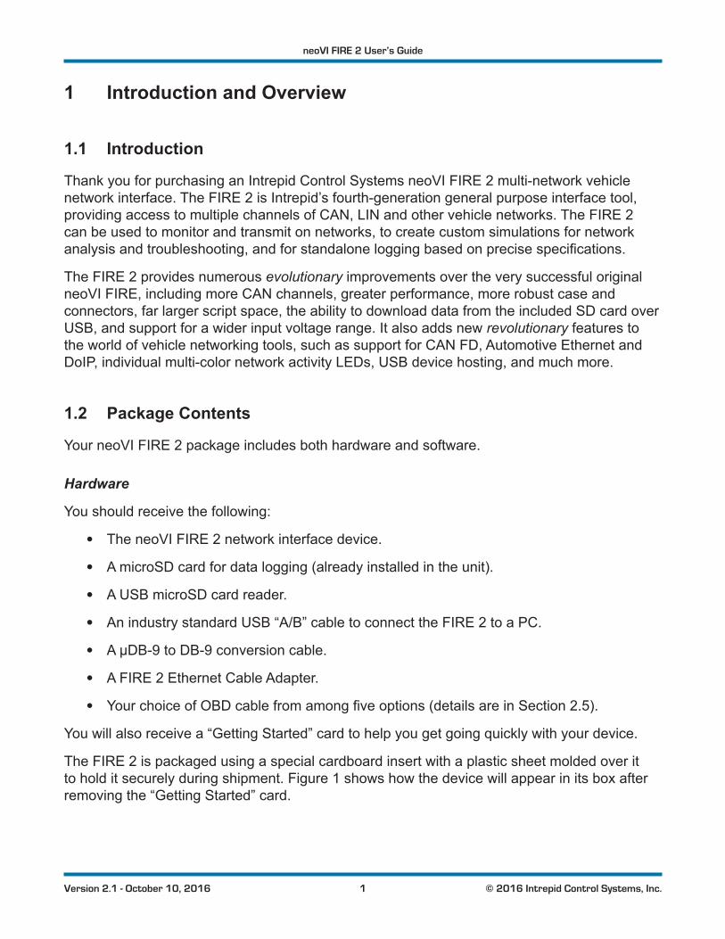
The FIRE 2 is packaged using a special cardboard insert with a plastic sheet molded over it to hold it securely during shipment. Figure 1 shows how the device will appear in its box after removing the “Getting Started” card.
neoVI FIRE 2 User’s Guide
2 © 2016 Intrepid Control Systems, Inc.Version 2.1 - October 10, 2016
Figure 1: neoVI FIRE 2 in its Protective Insert.
Lift up the plastic sheet, remove the FIRE 2, and then fold back the cardboard upon which it rested.Underneathyouwillfindthecablesandotheraccessorieslistedabove.Pleaseremove,unwrap and inspect all of the contents, an example of which is shown in Figure 2.
If anything is missing or damaged, please contact Intrepid for prompt assistance, using the information in Chapter 8. Detailed instructions for attaching the cables to your hardware are provided later in the document.
Note: While the USB cable in the FIRE 2 package uses industry standard connectors and pinouts, not all USB cables are the
same. To ensure reliable operation, please use the cable included with the FIRE 2. If you need to replace the original, be sure not to use one longer than 6’ (2 m) or you may experience problems with your hardware. If necessary, contact Intrepid for a replacement.
neoVI FIRE 2 User’s Guide
3 © 2016 Intrepid Control Systems, Inc.Version 2.1 - October 10, 2016
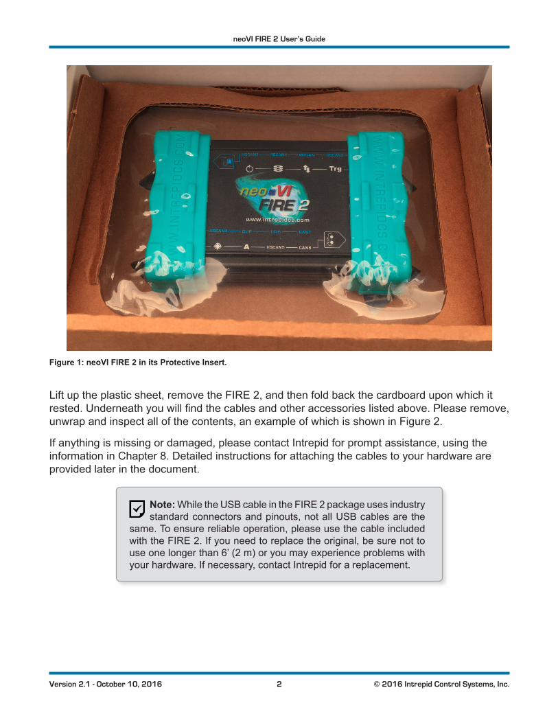
Figure 2: neoVI FIRE 2 Package Contents. Starting top center with the FIRE 2 itself and going clockwise: µDB-9 to DB-9 conversion cable; USB cable; microSD card reader; FIRE 2 Ethernet Cable Adapter; neoVI-OBD-1 cable. The software/driver CD can be found in the center. Note that the OBD cable you receive may differ from the one shown here.
Software
IntheFIRE2packageyouwillfindasoftware/driverCDcontaining:
• A copy of Intrepid’s Vehicle Spy vehicle network software.
• Drivers for the neoVI FIRE 2.
• AnAPIinstallkitcontainingtheneoVIExplorerutilityforconfiguringthedevice.
• Documentation materials.
Intrepid’s Vehicle Spy (often abbreviated as VSpy) is the “Swiss army knife” of automotive networking tools. It allows you to easily monitor and transmit on vehicle networks, and includes capabilities for ECU simulation, data acquisition, scripting, diagnostics, data analysis and much more.
The neoVI FIRE 2 and Vehicle Spy are designed to work together hand in hand, and we recommend purchasing a VSpy license to go along with your new hardware. If you did so, then a full copy of the software will be included on the software/driver CD. If you did not purchase
neoVI FIRE 2 User’s Guide
4 © 2016 Intrepid Control Systems, Inc.Version 2.1 - October 10, 2016
Vehicle Spy, a trial version of the program will be provided instead, which allows access to VSpy’s basic features.
It is also possible to control the neoVI FIRE 2 from within other software using one of the APIs that the device supports.
1.3 Operational Overview
The neoVI FIRE 2 is a compact but powerful hardware tool for working with vehicle networks. Its operation can broadly be broken down into three categories: network interfacing; data acquisition and logging; and simulation and scripting.
Vehicle Network Interfacing
One primary function of the neoVI FIRE 2 is to act as an interface between vehicle networks and a standard PC. Using the provided cables, you can connect the neoVI FIRE 2 to either a bench test setup or an actual vehicle, and monitor live network activity. All channels are captured simultaneously, and are hardware time-stamped with great accuracy. Data is transferred by the neoVI FIRE 2 from attached networks over a USB connection, where it can be viewed in software such as Vehicle Spy.
Data Acquisition and Standalone Logging
The FIRE 2 enables the acquisition of data from networks with precise control over collection parameters. It is designed to operate not just when connected to a PC, but also in standalone mode, running independently within a vehicle. You can write custom scripts that run in real time, logging data to the included microSD card. This data can later be downloaded to the PC for analysis, and this can be done conveniently over USB without the need to remove the card.
Simulation and Scripting
The neoVI FIRE 2 not only allows you to receive data from vehicle networks, but also to transmitonthem.UsingVehicleSpyorothersoftwareyoucandefinetransmitmessageswithcustom data and send them manually or on a schedule of your choosing. You can also write intelligent scripts that implement arbitrary logic, and compile them into CoreMinis that run within the device itself. This functionality allows you to create specialized test scenarios, and to simulateECUsandgateways.ItisalsopossibletoreflashECUsusingdatafromtheFIRE2’smicroSD card.
1.4 Summary of Key Features
WiththeneoVIFIRE2,we’vefitalotofpowerandfunctionalityintoatoughlittlepackage.Togive you an idea of how much you can do with the FIRE 2, here’s a summary of the device’s most important design, construction, operational and performance features.
neoVI FIRE 2 User’s Guide
5 © 2016 Intrepid Control Systems, Inc.Version 2.1 - October 10, 2016
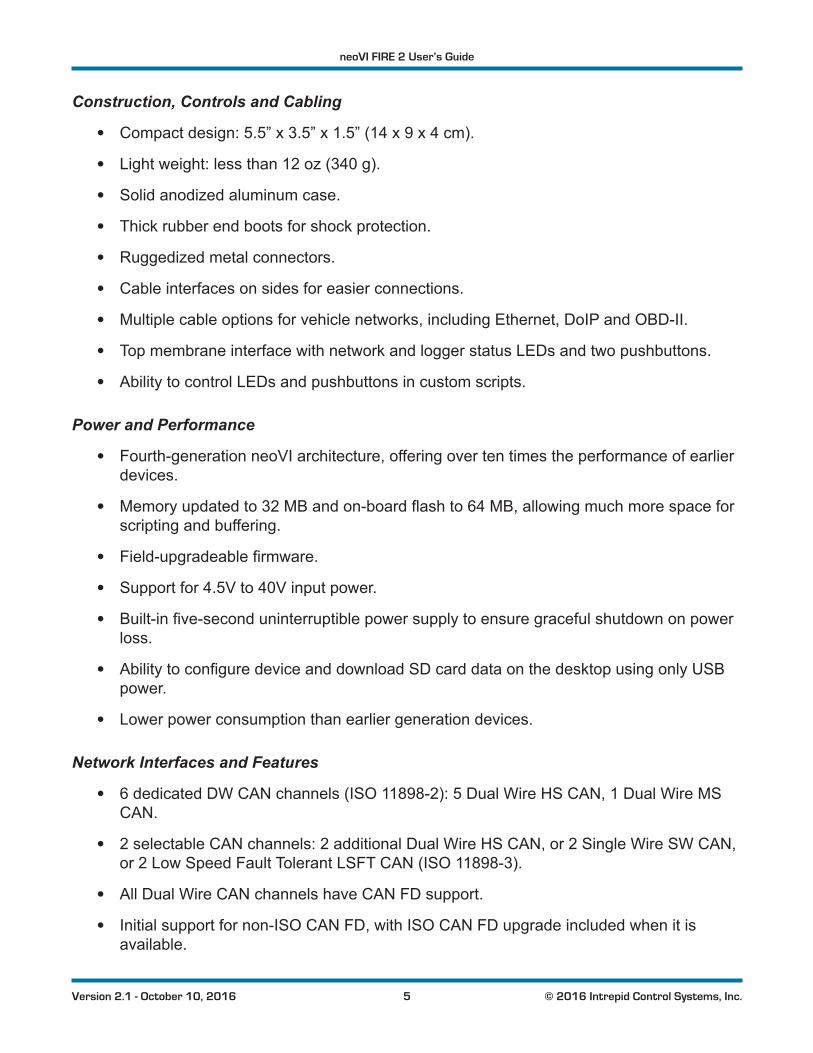
Construction, Controls and Cabling
• Compact design: 5.5” x 3.5” x 1.5” (14 x 9 x 4 cm).
• Light weight: less than 12 oz (340 g).
• Solid anodized aluminum case.
• Thick rubber end boots for shock protection.
• Ruggedized metal connectors.
• Cable interfaces on sides for easier connections.
• Multiple cable options for vehicle networks, including Ethernet, DoIP and OBD-II.
• Top membrane interface with network and logger status LEDs and two pushbuttons.
• Ability to control LEDs and pushbuttons in custom scripts.
Power and Performance
• Fourth-generation neoVI architecture, offering over ten times the performance of earlier devices.
• Memoryupdatedto32MBandon-boardflashto64MB,allowingmuchmorespaceforscripting and buffering.
• Field-upgradeablefirmware.
• Support for 4.5V to 40V input power.
• Built-infive-seconduninterruptiblepowersupplytoensuregracefulshutdownonpowerloss.
• AbilitytoconfiguredeviceanddownloadSDcarddataonthedesktopusingonlyUSBpower.
• Lower power consumption than earlier generation devices.
Network Interfaces and Features
• 6 dedicated DW CAN channels (ISO 11898-2): 5 Dual Wire HS CAN, 1 Dual Wire MS CAN.
• 2 selectable CAN channels: 2 additional Dual Wire HS CAN, or 2 Single Wire SW CAN, or 2 Low Speed Fault Tolerant LSFT CAN (ISO 11898-3).
• All Dual Wire CAN channels have CAN FD support.
• Initial support for non-ISO CAN FD, with ISO CAN FD upgrade included when it is available.
neoVI FIRE 2 User’s Guide
6 © 2016 Intrepid Control Systems, Inc.Version 2.1 - October 10, 2016
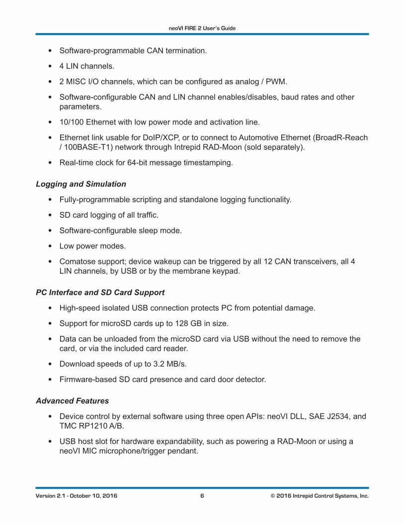
• Software-programmable CAN termination.
• 4 LIN channels.
• 2MISCI/Ochannels,whichcanbeconfiguredasanalog/PWM.
• Software-configurableCANandLINchannelenables/disables,baudratesandotherparameters.
• 10/100 Ethernet with low power mode and activation line.
• Ethernet link usable for DoIP/XCP, or to connect to Automotive Ethernet (BroadR-Reach / 100BASE-T1) network through Intrepid RAD-Moon (sold separately).
• Real-time clock for 64-bit message timestamping.
Logging and Simulation
• Fully-programmable scripting and standalone logging functionality.
• SDcardloggingofalltraffic.
• Software-configurablesleepmode.
• Low power modes.
• Comatose support; device wakeup can be triggered by all 12 CAN transceivers, all 4 LIN channels, by USB or by the membrane keypad.
PC Interface and SD Card Support
• High-speed isolated USB connection protects PC from potential damage.
• Support for microSD cards up to 128 GB in size.
• Data can be unloaded from the microSD card via USB without the need to remove the card, or via the included card reader.
• Download speeds of up to 3.2 MB/s.
• Firmware-based SD card presence and card door detector.
Advanced Features
• Device control by external software using three open APIs: neoVI DLL, SAE J2534, and TMC RP1210 A/B.
• USB host slot for hardware expandability, such as powering a RAD-Moon or using a neoVI MIC microphone/trigger pendant.
neoVI FIRE 2 User’s Guide
7 © 2016 Intrepid Control Systems, Inc.Version 2.1 - October 10, 2016
1.5 Hardware and Software Requirements
Only a small amount of hardware is required to use the neoVI FIRE 2:
• A vehicle network, either within an actual vehicle or in a test bench environment.
• A DC power supply capable of providing 4.5V to 40V of DC power, with a nominal current of 250 mA at 12V. Your network setup must include wiring capable of providing this power on pin 25 of a female DB-25 connector that connects to a FIRE 2 cable; see Chapter 7 for pinout details.
• A PC with an open standard USB 2.0 (or higher) port. You can use a USB hub, but we recommendthatthisbeapoweredhubtoensurethatsufficientpowerisprovided.
Additional hardware may be required for some uses of the device:
• Interfacing to a BroadR-Reach (100BASE-T1) Automotive Ethernet network requires an Intrepid RAD-Moon or similar media converter device.
• Additional cables may be needed, depending on the nature of the network to which the neoVI FIRE 2 is being connected.
Intrepid’s Vehicle Spy Professional is recommended for use with the FIRE 2, and provides everything you need to set up your hardware and use all of its capabilities. The setup program for VSpy will also install the necessary drivers for your FIRE 2. If you do not have a VSpy license, you can use the Vehicle Spy trial version for basic network interfacing and driver setup. Drivers can also be set up using the API kit installer. All of this software can be found on the disc that comes with the FIRE 2, or if necessary, can be downloaded from the Intrepid web site at http://www.intrepidcs.com. Installation instructions can be found in Chapter 3.
PleaserefertotheVehicleSpydocumentationforitsmorespecificPChardwareandoperatingsystem requirements and recommendations. Note, however, that Vehicle Spy will run on most modern Windows-based PCs.

neoVI FIRE 2 User’s Guide
8 © 2016 Intrepid Control Systems, Inc.Version 2.1 - October 10, 2016
2 A Tour of neoVI FIRE2 HardwareLet’s now take a short tour of the neoVI FIRE 2’s hardware. We’ll examine the device from all sides, showing its external components and explaining what each does. This will help you becomemorefamiliarwiththeunitsoyoucanmoreeasilysetup,configureanduseit.
Like many Intrepid products, the neoVI FIRE 2 is designed so that all of its connectors are located on its sides, making the device easier to use in cramped quarters. We’ll refer to these as the left side and right side of the unit, as oriented when facing the device with its top label text readable.
Warning: The neoVI FIRE 2 is a complex device that does not contain any user-serviceable parts. Do not attempt to open the
caseoftheneoVIFIRE2unlessspecificallyinstructedtodosobyan Intrepid Control Systems technician, or you risk possible injury or damage to the unit.
2.1 Case and Overall Design
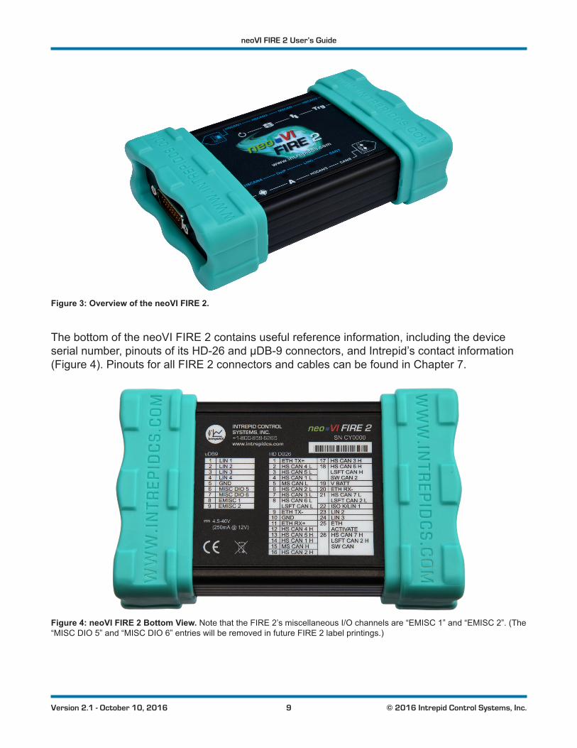
The neoVI FIRE 2 is enclosed in a sturdy black-anodized metal case. The device has been designed and tested for in-vehicle use, and is operational in a temperature range from -40°C to +85°C. An overall view of the neoVI FIRE 2 can be seen in Figure 3.
Connectors and ports are often a point of failure with hardware devices. To ensure that the neoVI FIRE 2 provides you with years of reliable service, Intrepid has ruggedized the physical interfaces on the device by using reinforced metal connectors.
To further protect the device against bumps and drops, it has cyan-colored rubber bumpers on both ends. These bumpers are removable, but there is no need to do this under normal circumstances, and we recommend that you leave them in place.
neoVI FIRE 2 User’s Guide
9 © 2016 Intrepid Control Systems, Inc.Version 2.1 - October 10, 2016
Figure 3: Overview of the neoVI FIRE 2.
The bottom of the neoVI FIRE 2 contains useful reference information, including the device serial number, pinouts of its HD-26 and µDB-9 connectors, and Intrepid’s contact information (Figure 4). Pinouts for all FIRE 2 connectors and cables can be found in Chapter 7.
Figure 4: neoVI FIRE 2 Bottom View. Note that the FIRE 2’s miscellaneous I/O channels are “EMISC 1” and “EMISC 2”. (The “MISC DIO 5” and “MISC DIO 6” entries will be removed in future FIRE 2 label printings.)
neoVI FIRE 2 User’s Guide
10 © 2016 Intrepid Control Systems, Inc.Version 2.1 - October 10, 2016
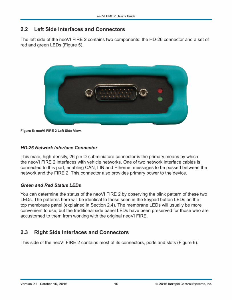
2.2 Left Side Interfaces and Connectors
The left side of the neoVI FIRE 2 contains two components: the HD-26 connector and a set of red and green LEDs (Figure 5).
Figure 5: neoVI FIRE 2 Left Side View.
HD-26 Network Interface Connector
This male, high-density, 26-pin D-subminiature connector is the primary means by which the neoVI FIRE 2 interfaces with vehicle networks. One of two network interface cables is connected to this port, enabling CAN, LIN and Ethernet messages to be passed between the network and the FIRE 2. This connector also provides primary power to the device.
Green and Red Status LEDs
You can determine the status of the neoVI FIRE 2 by observing the blink pattern of these two LEDs. The patterns here will be identical to those seen in the keypad button LEDs on the top membrane panel (explained in Section 2.4). The membrane LEDs will usually be more convenient to use, but the traditional side panel LEDs have been preserved for those who are accustomed to them from working with the original neoVI FIRE.
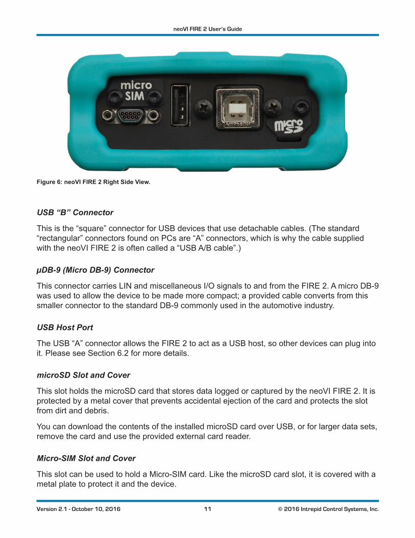
2.3 Right Side Interfaces and Connectors
This side of the neoVI FIRE 2 contains most of its connectors, ports and slots (Figure 6).
neoVI FIRE 2 User’s Guide
11 © 2016 Intrepid Control Systems, Inc.Version 2.1 - October 10, 2016
Figure 6: neoVI FIRE 2 Right Side View.
USB “B” Connector
This is the “square” connector for USB devices that use detachable cables. (The standard “rectangular” connectors found on PCs are “A” connectors, which is why the cable supplied with the neoVI FIRE 2 is often called a “USB A/B cable”.)
µDB-9 (Micro DB-9) Connector
This connector carries LIN and miscellaneous I/O signals to and from the FIRE 2. A micro DB-9 was used to allow the device to be made more compact; a provided cable converts from this smaller connector to the standard DB-9 commonly used in the automotive industry.
USB Host Port
The USB “A” connector allows the FIRE 2 to act as a USB host, so other devices can plug into it. Please see Section 6.2 for more details.
microSD Slot and Cover
This slot holds the microSD card that stores data logged or captured by the neoVI FIRE 2. It is protected by a metal cover that prevents accidental ejection of the card and protects the slot from dirt and debris.
You can download the contents of the installed microSD card over USB, or for larger data sets, remove the card and use the provided external card reader.
Micro-SIM Slot and Cover
This slot can be used to hold a Micro-SIM card. Like the microSD card slot, it is covered with a metal plate to protect it and the device.
neoVI FIRE 2 User’s Guide
12 © 2016 Intrepid Control Systems, Inc.Version 2.1 - October 10, 2016
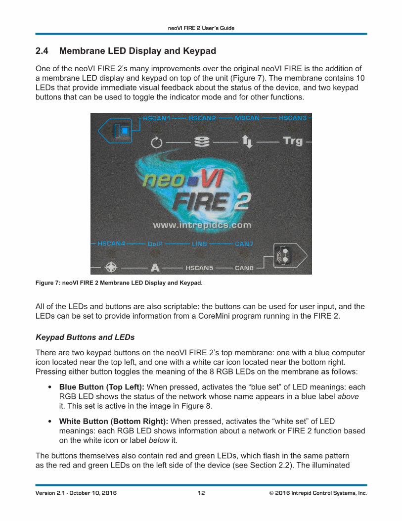
2.4 Membrane LED Display and Keypad
One of the neoVI FIRE 2’s many improvements over the original neoVI FIRE is the addition of a membrane LED display and keypad on top of the unit (Figure 7). The membrane contains 10 LEDs that provide immediate visual feedback about the status of the device, and two keypad buttons that can be used to toggle the indicator mode and for other functions.
Figure 7: neoVI FIRE 2 Membrane LED Display and Keypad.
All of the LEDs and buttons are also scriptable: the buttons can be used for user input, and the LEDs can be set to provide information from a CoreMini program running in the FIRE 2.
Keypad Buttons and LEDs
There are two keypad buttons on the neoVI FIRE 2’s top membrane: one with a blue computer icon located near the top left, and one with a white car icon located near the bottom right. Pressing either button toggles the meaning of the 8 RGB LEDs on the membrane as follows:
• Blue Button (Top Left): When pressed, activates the “blue set” of LED meanings: each RGB LED shows the status of the network whose name appears in a blue label above it. This set is active in the image in Figure 8.
• White Button (Bottom Right): When pressed, activates the “white set” of LED meanings: each RGB LED shows information about a network or FIRE 2 function based on the white icon or label below it.
ThebuttonsthemselvesalsocontainredandgreenLEDs,whichflashinthesamepatternas the red and green LEDs on the left side of the device (see Section 2.2). The illuminated
neoVI FIRE 2 User’s Guide
13 © 2016 Intrepid Control Systems, Inc.Version 2.1 - October 10, 2016
LEDs show which set of indicator meanings is active, and may also be more convenient for monitoring general device status than the left-side LEDs.
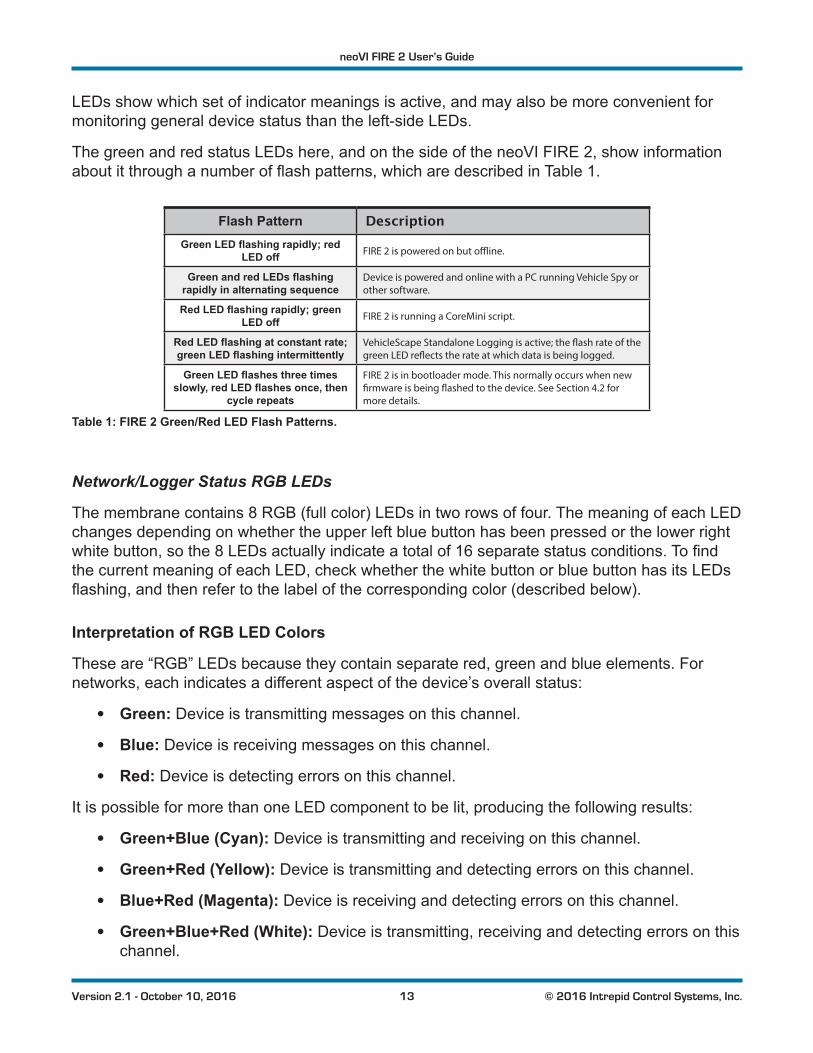
The green and red status LEDs here, and on the side of the neoVI FIRE 2, show information aboutitthroughanumberofflashpatterns,whicharedescribedinTable 1.
Flash Pattern DescriptionGreen LED flashing rapidly; red
LED off FIRE 2 is powered on but offline.
Green and red LEDs flashing rapidly in alternating sequence
Device is powered and online with a PC running Vehicle Spy or other software.
Red LED flashing rapidly; green LED off FIRE 2 is running a CoreMini script.
Red LED flashing at constant rate; green LED flashing intermittently
VehicleScape Standalone Logging is active; the flash rate of the green LED reflects the rate at which data is being logged.
Green LED flashes three times slowly, red LED flashes once, then
cycle repeats
FIRE 2 is in bootloader mode. This normally occurs when new firmware is being flashed to the device. See Section 4.2 for more details.
Table 1: FIRE 2 Green/Red LED Flash Patterns.
Network/Logger Status RGB LEDs
The membrane contains 8 RGB (full color) LEDs in two rows of four. The meaning of each LED changes depending on whether the upper left blue button has been pressed or the lower right whitebutton,sothe8LEDsactuallyindicateatotalof16separatestatusconditions.Tofindthe current meaning of each LED, check whether the white button or blue button has its LEDs flashing,andthenrefertothelabelofthecorrespondingcolor(describedbelow).
Interpretation of RGB LED Colors
These are “RGB” LEDs because they contain separate red, green and blue elements. For networks, each indicates a different aspect of the device’s overall status:
• Green: Device is transmitting messages on this channel.
• Blue: Device is receiving messages on this channel.
• Red: Device is detecting errors on this channel.
It is possible for more than one LED component to be lit, producing the following results:
• Green+Blue (Cyan): Device is transmitting and receiving on this channel.
• Green+Red (Yellow): Device is transmitting and detecting errors on this channel.
• Blue+Red (Magenta): Device is receiving and detecting errors on this channel.
• Green+Blue+Red (White): Device is transmitting, receiving and detecting errors on this channel.
neoVI FIRE 2 User’s Guide
14 © 2016 Intrepid Control Systems, Inc.Version 2.1 - October 10, 2016
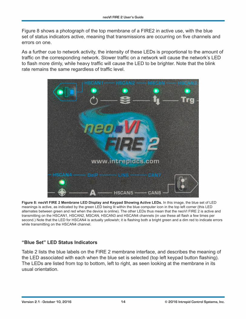
Figure 8 shows a photograph of the top membrane of a FIRE2 in active use, with the blue setofstatusindicatorsactive,meaningthattransmissionsareoccurringonfivechannelsanderrors on one.
As a further cue to network activity, the intensity of these LEDs is proportional to the amount of trafficonthecorrespondingnetwork.Slowertrafficonanetworkwillcausethenetwork’sLEDtoflashmoredimly,whileheavytrafficwillcausetheLEDtobebrighter.Notethattheblinkrateremainsthesameregardlessoftrafficlevel.
Figure 8: neoVI FIRE 2 Membrane LED Display and Keypad Showing Active LEDs. In this image, the blue set of LED meanings is active, as indicated by the green LED being lit within the blue computer icon in the top left corner (this LED alternates between green and red when the device is online). The other LEDs thus mean that the neoVI FIRE 2 is active and transmittingontheHSCAN1,HSCAN2,MSCAN,HSCAN3andHSCAN4channels(inusetheseallflashafewtimespersecond.)NotethattheLEDforHSCAN4isactuallyyellowish;itisflashingbothabrightgreenandadimredtoindicateerrorswhile transmitting on the HSCAN4 channel.
“Blue Set” LED Status Indicators
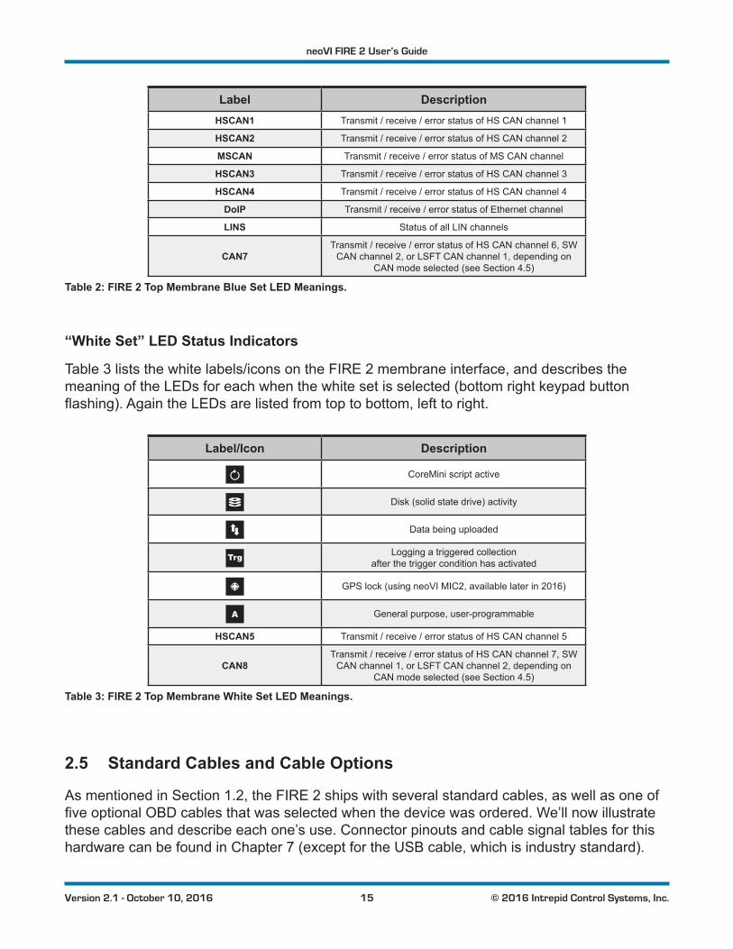
Table 2 lists the blue labels on the FIRE 2 membrane interface, and describes the meaning of theLEDassociatedwitheachwhenthebluesetisselected(topleftkeypadbuttonflashing).The LEDs are listed from top to bottom, left to right, as seen looking at the membrane in its usual orientation.
neoVI FIRE 2 User’s Guide
15 © 2016 Intrepid Control Systems, Inc.Version 2.1 - October 10, 2016
Label DescriptionHSCAN1 Transmit / receive / error status of HS CAN channel 1
HSCAN2 Transmit / receive / error status of HS CAN channel 2
MSCAN Transmit / receive / error status of MS CAN channel
HSCAN3 Transmit / receive / error status of HS CAN channel 3
HSCAN4 Transmit / receive / error status of HS CAN channel 4
DoIP Transmit / receive / error status of Ethernet channel
LINS Status of all LIN channels
CAN7Transmit / receive / error status of HS CAN channel 6, SW
CAN channel 2, or LSFT CAN channel 1, depending on CAN mode selected (see Section 4.5)
Table 2: FIRE 2 Top Membrane Blue Set LED Meanings.
“White Set” LED Status Indicators
Table 3 lists the white labels/icons on the FIRE 2 membrane interface, and describes the meaning of the LEDs for each when the white set is selected (bottom right keypad button flashing).AgaintheLEDsarelistedfromtoptobottom,lefttoright.
Label/Icon Description
CoreMini script active
Disk (solid state drive) activity
Data being uploaded
Logging a triggered collection after the trigger condition has activated
GPS lock (using neoVI MIC2, available later in 2016)
General purpose, user-programmable
HSCAN5 Transmit / receive / error status of HS CAN channel 5
CAN8Transmit / receive / error status of HS CAN channel 7, SW
CAN channel 1, or LSFT CAN channel 2, depending on CAN mode selected (see Section 4.5)
Table 3: FIRE 2 Top Membrane White Set LED Meanings.
2.5 Standard Cables and Cable Options
As mentioned in Section 1.2, the FIRE 2 ships with several standard cables, as well as one of fiveoptionalOBDcablesthatwasselectedwhenthedevicewasordered.We’llnowillustratethese cables and describe each one’s use. Connector pinouts and cable signal tables for this hardware can be found in Chapter 7 (except for the USB cable, which is industry standard).
neoVI FIRE 2 User’s Guide
16 © 2016 Intrepid Control Systems, Inc.Version 2.1 - October 10, 2016
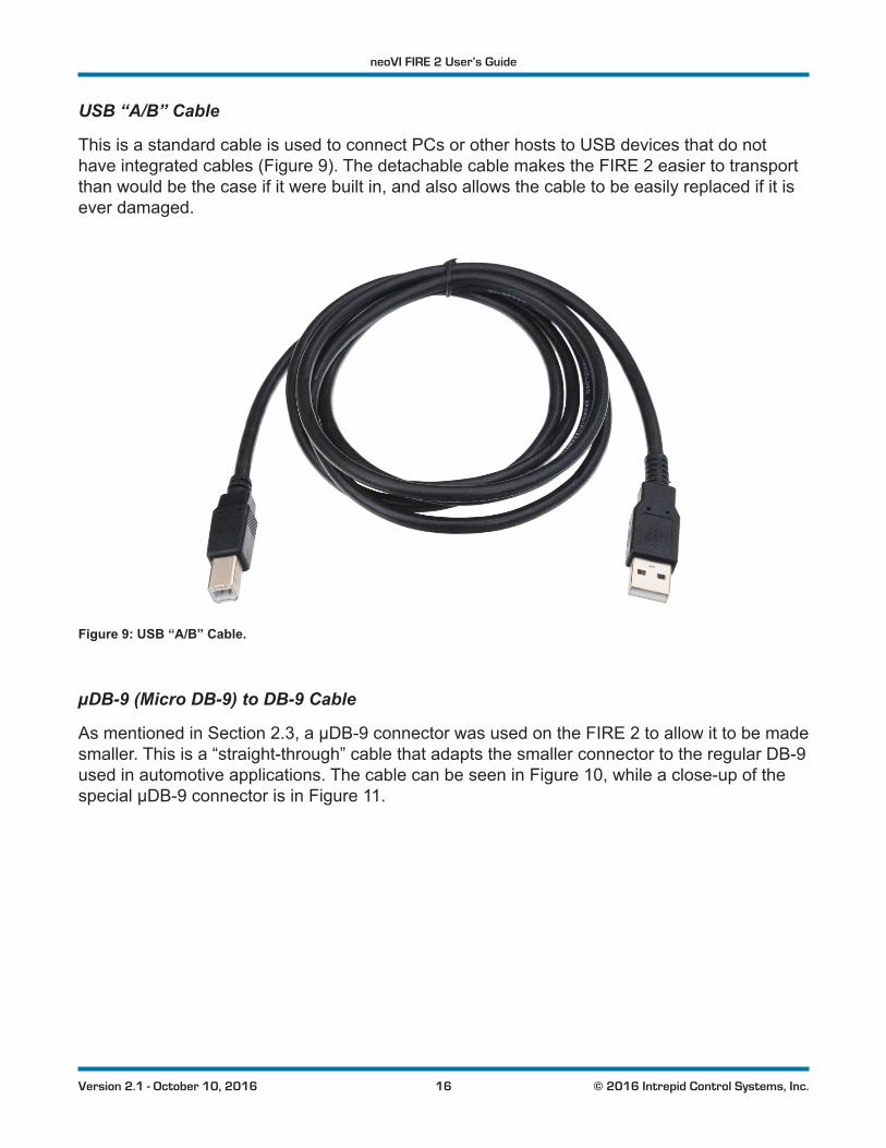
USB “A/B” Cable
This is a standard cable is used to connect PCs or other hosts to USB devices that do not have integrated cables (Figure 9). The detachable cable makes the FIRE 2 easier to transport than would be the case if it were built in, and also allows the cable to be easily replaced if it is ever damaged.
Figure 9: USB “A/B” Cable.
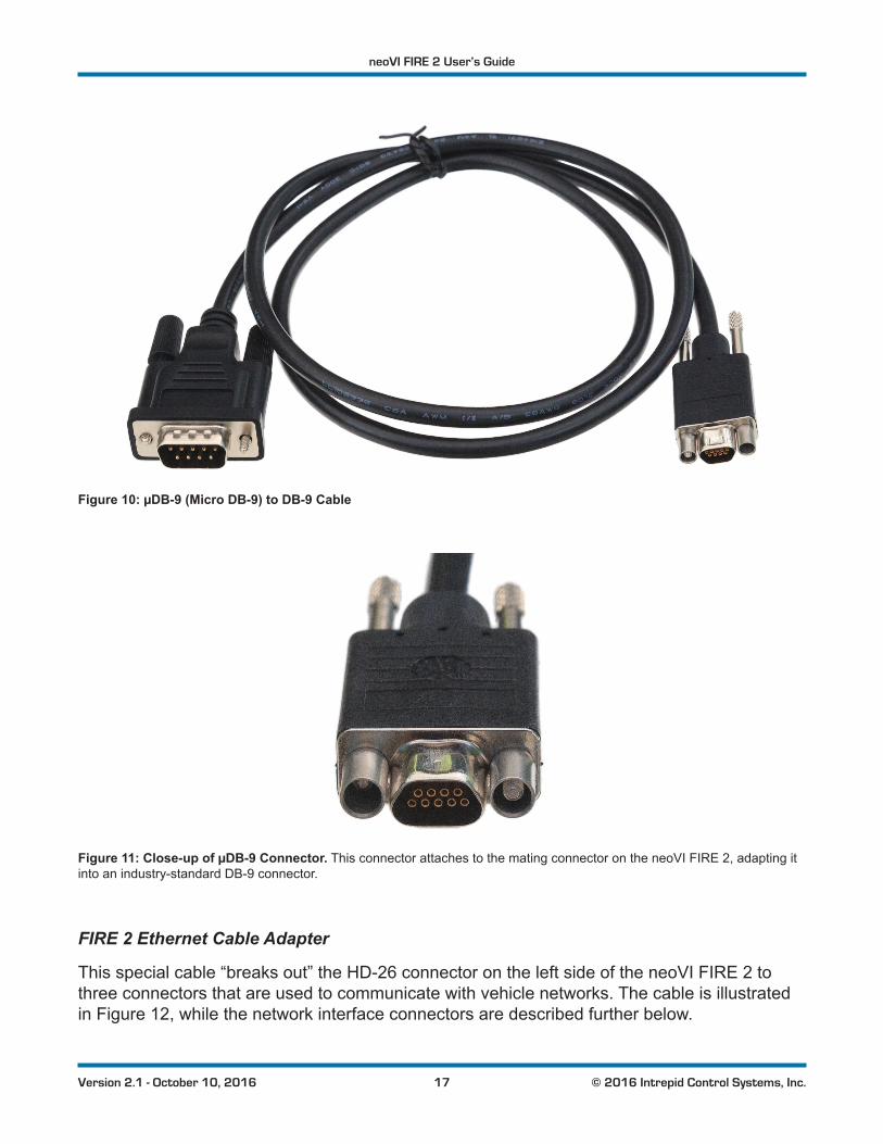
µDB-9 (Micro DB-9) to DB-9 Cable
As mentioned in Section 2.3, a µDB-9 connector was used on the FIRE 2 to allow it to be made smaller. This is a “straight-through” cable that adapts the smaller connector to the regular DB-9 used in automotive applications. The cable can be seen in Figure 10, while a close-up of the special µDB-9 connector is in Figure 11.
neoVI FIRE 2 User’s Guide
17 © 2016 Intrepid Control Systems, Inc.Version 2.1 - October 10, 2016
Figure 10: µDB-9 (Micro DB-9) to DB-9 Cable
Figure 11: Close-up of µDB-9 Connector. This connector attaches to the mating connector on the neoVI FIRE 2, adapting it into an industry-standard DB-9 connector.
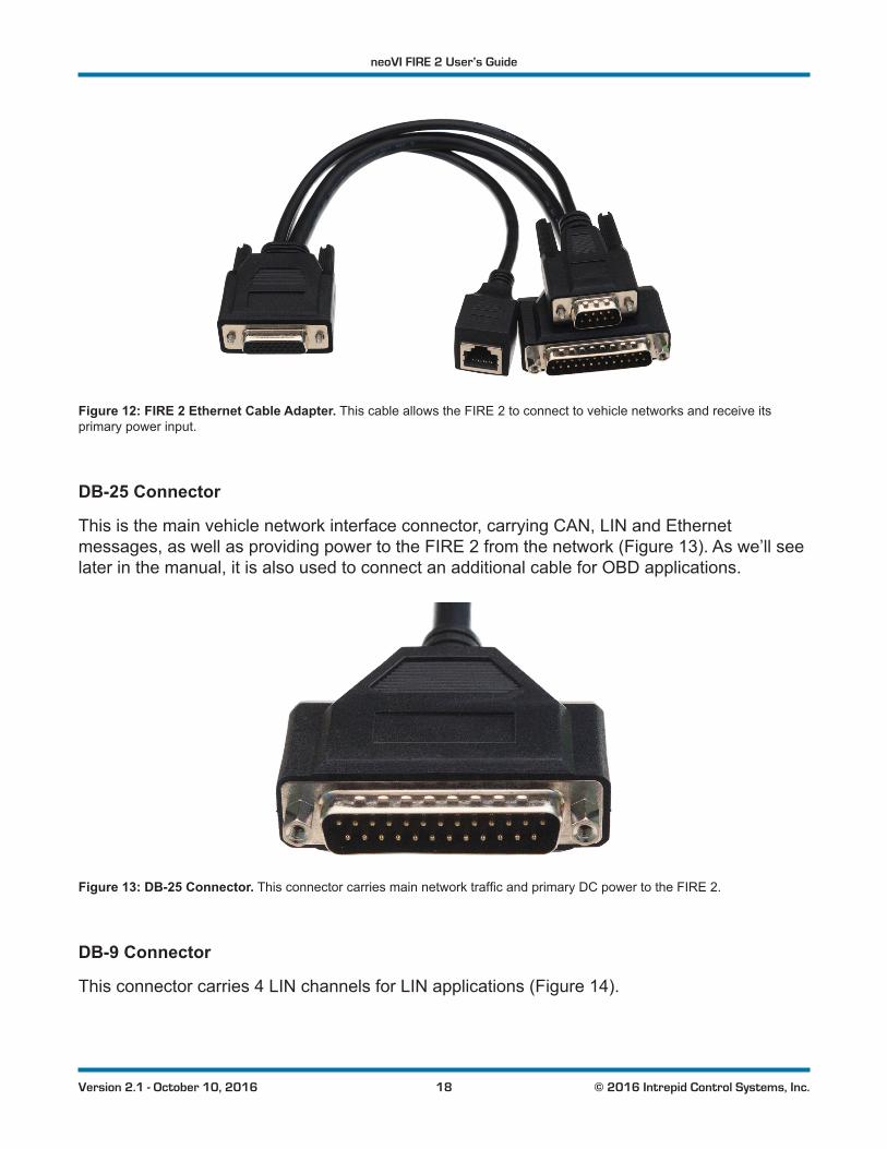
FIRE 2 Ethernet Cable Adapter
This special cable “breaks out” the HD-26 connector on the left side of the neoVI FIRE 2 to three connectors that are used to communicate with vehicle networks. The cable is illustrated in Figure 12, while the network interface connectors are described further below.
neoVI FIRE 2 User’s Guide
18 © 2016 Intrepid Control Systems, Inc.Version 2.1 - October 10, 2016
Figure 12: FIRE 2 Ethernet Cable Adapter. This cable allows the FIRE 2 to connect to vehicle networks and receive its primary power input.
DB-25 Connector
This is the main vehicle network interface connector, carrying CAN, LIN and Ethernet messages, as well as providing power to the FIRE 2 from the network (Figure 13). As we’ll see later in the manual, it is also used to connect an additional cable for OBD applications.
Figure 13: DB-25 Connector.ThisconnectorcarriesmainnetworktrafficandprimaryDCpowertotheFIRE2.
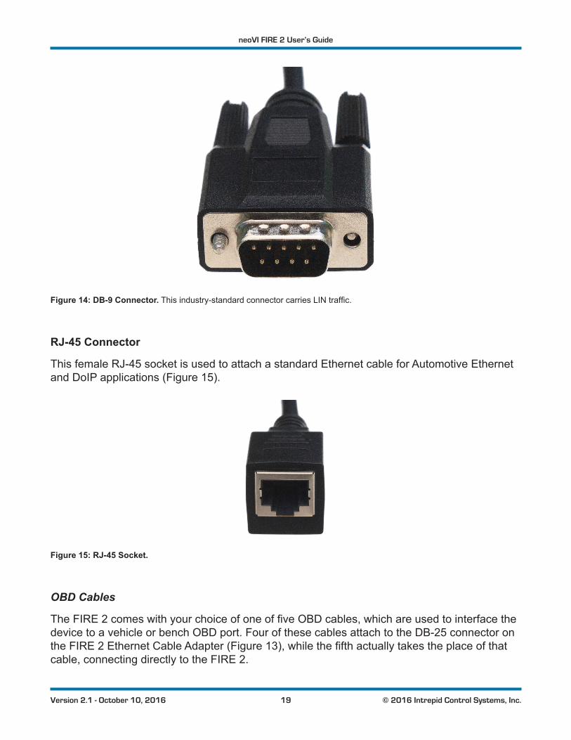
DB-9 Connector
This connector carries 4 LIN channels for LIN applications (Figure 14).
neoVI FIRE 2 User’s Guide
19 © 2016 Intrepid Control Systems, Inc.Version 2.1 - October 10, 2016
Figure 14: DB-9 Connector.Thisindustry-standardconnectorcarriesLINtraffic.
RJ-45 Connector
This female RJ-45 socket is used to attach a standard Ethernet cable for Automotive Ethernet and DoIP applications (Figure 15).
Figure 15: RJ-45 Socket.
OBD Cables
TheFIRE2comeswithyourchoiceofoneoffiveOBDcables,whichareusedtointerfacethedevice to a vehicle or bench OBD port. Four of these cables attach to the DB-25 connector on the FIRE 2 Ethernet Cable Adapter (Figure 13),whilethefifthactuallytakestheplaceofthatcable, connecting directly to the FIRE 2.
neoVI FIRE 2 User’s Guide
20 © 2016 Intrepid Control Systems, Inc.Version 2.1 - October 10, 2016
See Section 3.3 for hookup diagrams that show how to connect all of these cables to the FIRE 2 and your network or bench.
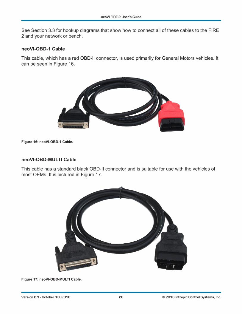
neoVI-OBD-1 Cable
This cable, which has a red OBD-II connector, is used primarily for General Motors vehicles. It can be seen in Figure 16.
Figure 16: neoVI-OBD-1 Cable.
neoVI-OBD-MULTI Cable
This cable has a standard black OBD-II connector and is suitable for use with the vehicles of most OEMs. It is pictured in Figure 17.
Figure 17: neoVI-OBD-MULTI Cable.
neoVI FIRE 2 User’s Guide
21 © 2016 Intrepid Control Systems, Inc.Version 2.1 - October 10, 2016
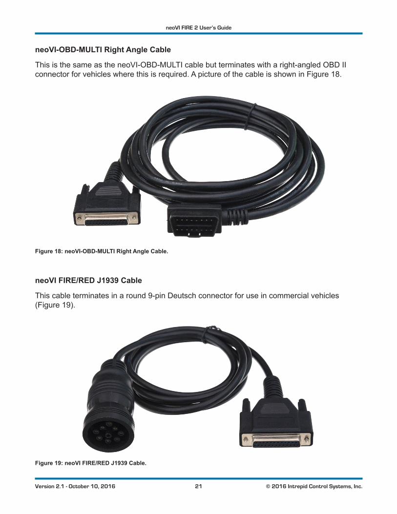
neoVI-OBD-MULTI Right Angle Cable
This is the same as the neoVI-OBD-MULTI cable but terminates with a right-angled OBD II connector for vehicles where this is required. A picture of the cable is shown in Figure 18.
Figure 18: neoVI-OBD-MULTI Right Angle Cable.
neoVI FIRE/RED J1939 Cable
This cable terminates in a round 9-pin Deutsch connector for use in commercial vehicles (Figure 19).
Figure 19: neoVI FIRE/RED J1939 Cable.
neoVI FIRE 2 User’s Guide
22 © 2016 Intrepid Control Systems, Inc.Version 2.1 - October 10, 2016
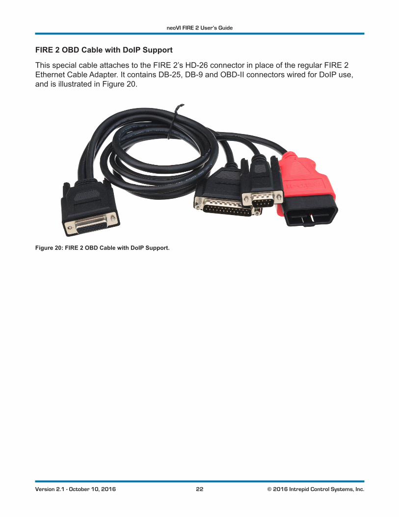
FIRE 2 OBD Cable with DoIP Support
This special cable attaches to the FIRE 2’s HD-26 connector in place of the regular FIRE 2 Ethernet Cable Adapter. It contains DB-25, DB-9 and OBD-II connectors wired for DoIP use, and is illustrated in Figure 20.
Figure 20: FIRE 2 OBD Cable with DoIP Support.
neoVI FIRE 2 User’s Guide
23 © 2016 Intrepid Control Systems, Inc.Version 2.1 - October 10, 2016
3 Hardware and Software SetupIn this chapter we will explain the steps necessary to set up your neoVI FIRE 2 to work with a vehicle network. This will include explaining how to install the required software and drivers, connect cables between the FIRE 2 and the network, and link the unit to a PC.
Note that because vehicle and test bench setups will vary, we can only show a typical case here. You may need to alter these instructions to suit your particular needs.
3.1 Vehicle Spy and Driver Installation and Setup
It is possible to install your hardware and software in either order. However, the neoVI FIRE 2 requires special drivers to function properly, which are installed automatically by the included software setup programs. If you connect the hardware before the drivers are installed, it will notworkcorrectly.Forthisreason,werecommendinstallingthesoftwarefirst.
As mentioned earlier, a full licensed version of Vehicle Spy is recommended in order to allow you to get the most from your neoVI FIRE 2. If you purchase Vehicle Spy, its installer will be included on the software disc that comes with the device; if not, a more limited trial version will be provided instead.
Note: A separate driver installer is provided for those who will be interfacing to the neoVI FIRE 2 using its API, rather than
using Vehicle Spy. Please see Section 3.2 for details.
Installing Vehicle Spy (Professional or Trial)
The installation process is very similar for both the full and trial versions, though there may besomeslightdifferencesbetweenthefiguresinthisdocumentandwhatyouseeonyourscreen. Vehicle Spy 3 uses an automated installer, which will do most of the work for you. Simply follow the instructions below to set up the program on your computer.
1. Load the Software and Documentation Disc: Put the disc that came with your neoVI FIRE 2 into the optical drive of your computer. A few seconds later, the ICS software installation menu should appear on your computer screen, as shown in Figure 21.
Note: On some computers this window may not appear automatically. If this occurs, start Windows Explorer, navigate
to the disc’s letter under Computer,andthendouble-click thefileicsAutoPlay.exe to open the menu.
neoVI FIRE 2 User’s Guide
24 © 2016 Intrepid Control Systems, Inc.Version 2.1 - October 10, 2016
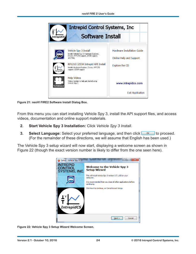
Figure 21: neoVI FIRE2 Software Install Dialog Box.
FromthismenuyoucanstartinstallingVehicleSpy3,installtheAPIsupportfiles,andaccessvideos, documentation and online support materials.
2. Start Vehicle Spy 3 Installation: Click Vehicle Spy 3 Install.
3. Select Language: Select your preferred language, and then click to proceed. (For the remainder of these directions, we will assume that English has been used.)
The Vehicle Spy 3 setup wizard will now start, displaying a welcome screen as shown in Figure 22 (though the exact version number is likely to differ from the one seen here).
Figure 22: Vehicle Spy 3 Setup Wizard Welcome Screen.
neoVI FIRE 2 User’s Guide
25 © 2016 Intrepid Control Systems, Inc.Version 2.1 - October 10, 2016
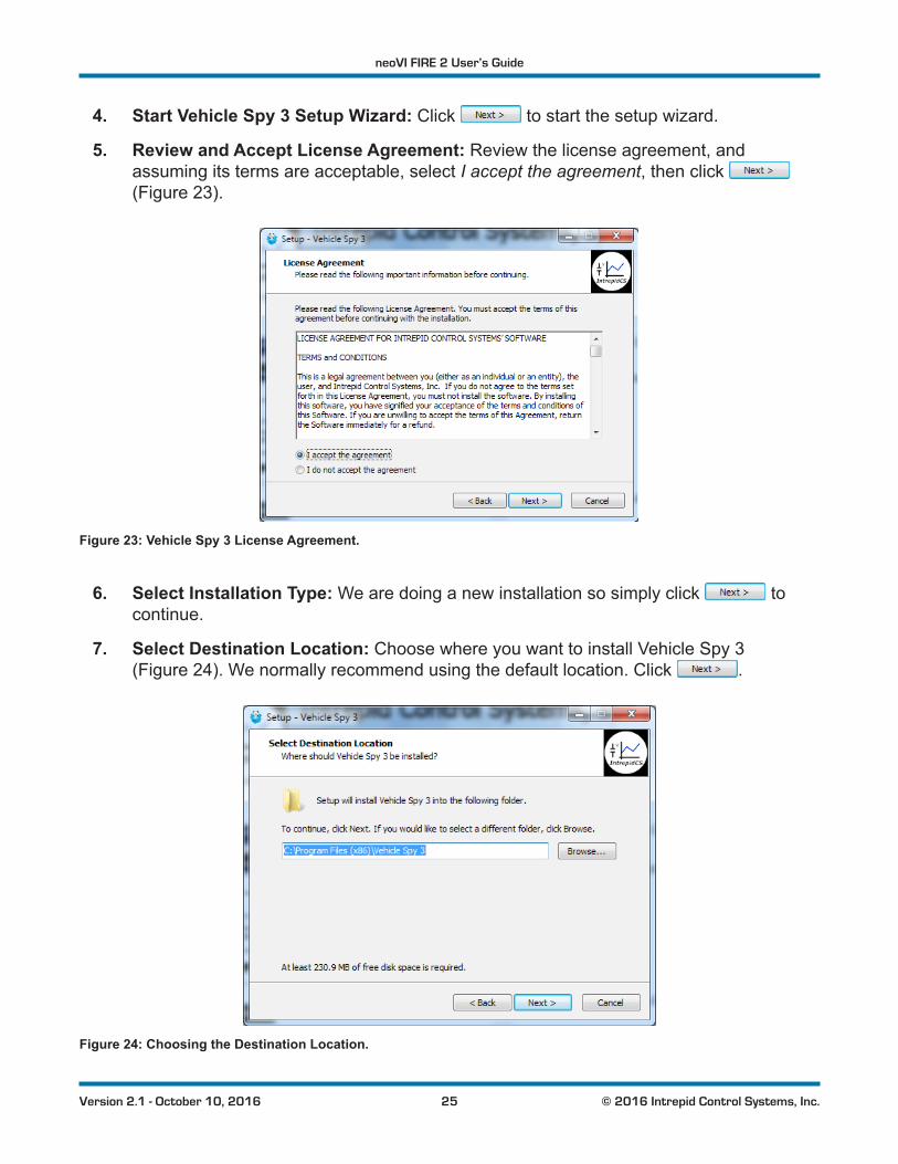
4. Start Vehicle Spy 3 Setup Wizard: Click to start the setup wizard.
5. Review and Accept License Agreement: Review the license agreement, and assuming its terms are acceptable, select I accept the agreement, then click (Figure 23).
Figure 23: Vehicle Spy 3 License Agreement.
6. Select Installation Type: We are doing a new installation so simply click to continue.
7. Select Destination Location: Choose where you want to install Vehicle Spy 3 (Figure 24). We normally recommend using the default location. Click .
Figure 24: Choosing the Destination Location.
neoVI FIRE 2 User’s Guide
26 © 2016 Intrepid Control Systems, Inc.Version 2.1 - October 10, 2016
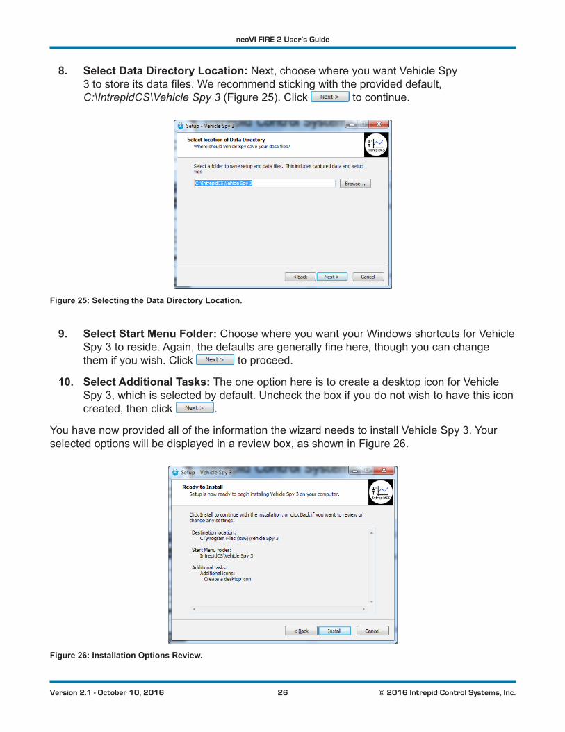
8. Select Data Directory Location: Next, choose where you want Vehicle Spy 3tostoreitsdatafiles.Werecommendstickingwiththeprovideddefault,C:\IntrepidCS\Vehicle Spy 3 (Figure 25). Click to continue.
Figure 25: Selecting the Data Directory Location.
9. Select Start Menu Folder: Choose where you want your Windows shortcuts for Vehicle Spy3toreside.Again,thedefaultsaregenerallyfinehere,thoughyoucanchangethem if you wish. Click to proceed.
10. Select Additional Tasks: The one option here is to create a desktop icon for Vehicle Spy 3, which is selected by default. Uncheck the box if you do not wish to have this icon created, then click .
You have now provided all of the information the wizard needs to install Vehicle Spy 3. Your selected options will be displayed in a review box, as shown in Figure 26.
Figure 26: Installation Options Review.
neoVI FIRE 2 User’s Guide
27 © 2016 Intrepid Control Systems, Inc.Version 2.1 - October 10, 2016
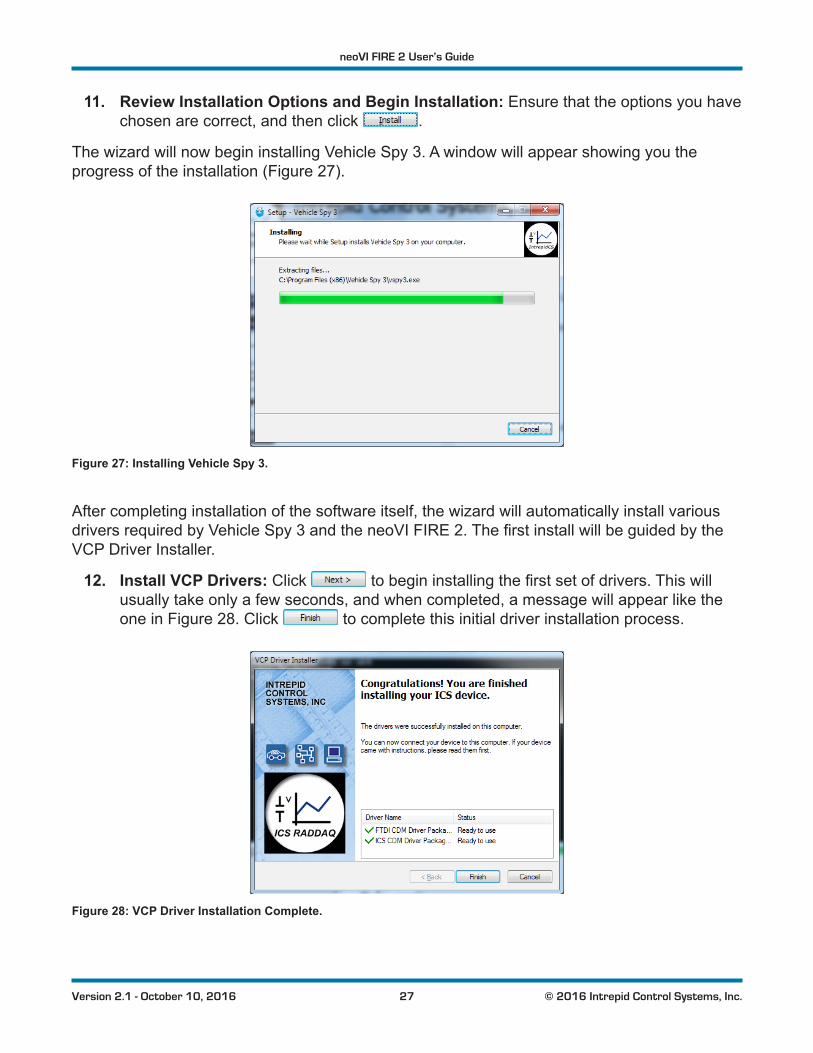
11. Review Installation Options and Begin Installation: Ensure that the options you have chosen are correct, and then click .
The wizard will now begin installing Vehicle Spy 3. A window will appear showing you the progress of the installation (Figure 27).
Figure 27: Installing Vehicle Spy 3.
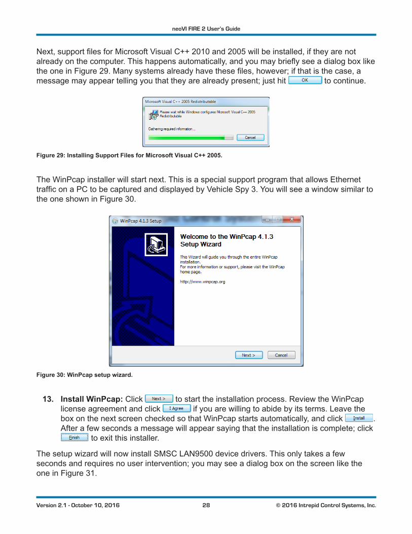
After completing installation of the software itself, the wizard will automatically install various driversrequiredbyVehicleSpy3andtheneoVIFIRE2.ThefirstinstallwillbeguidedbytheVCP Driver Installer.
12. Install VCP Drivers: Click tobegininstallingthefirstsetofdrivers.Thiswillusually take only a few seconds, and when completed, a message will appear like the one in Figure 28. Click to complete this initial driver installation process.
Figure 28: VCP Driver Installation Complete.
neoVI FIRE 2 User’s Guide
28 © 2016 Intrepid Control Systems, Inc.Version 2.1 - October 10, 2016
Next,supportfilesforMicrosoftVisualC++2010and2005willbeinstalled,iftheyarenotalreadyonthecomputer.Thishappensautomatically,andyoumaybrieflyseeadialogboxlikethe one in Figure 29.Manysystemsalreadyhavethesefiles,however;ifthatisthecase,amessage may appear telling you that they are already present; just hit to continue.
Figure 29: Installing Support Files for Microsoft Visual C++ 2005.
The WinPcap installer will start next. This is a special support program that allows Ethernet trafficonaPCtobecapturedanddisplayedbyVehicleSpy3.Youwillseeawindowsimilartothe one shown in Figure 30.
Figure 30: WinPcap setup wizard.
13. Install WinPcap: Click to start the installation process. Review the WinPcap license agreement and click if you are willing to abide by its terms. Leave the box on the next screen checked so that WinPcap starts automatically, and click . After a few seconds a message will appear saying that the installation is complete; click
to exit this installer.
The setup wizard will now install SMSC LAN9500 device drivers. This only takes a few seconds and requires no user intervention; you may see a dialog box on the screen like the one in Figure 31.
neoVI FIRE 2 User’s Guide
29 © 2016 Intrepid Control Systems, Inc.Version 2.1 - October 10, 2016
Figure 31: SMSC LAN9500 device driver installation.
AnotherICSdriverinstallerdialogboxwillnowappear,similartothefirstone.
14. Install ICS Port Drivers: Click to begin installing the ICS port drivers.
At this point you may receive a prompt from Windows like the one shown in Figure 32. Please click to authorize driver installation.
Figure 32: Windows Security Dialog Box.
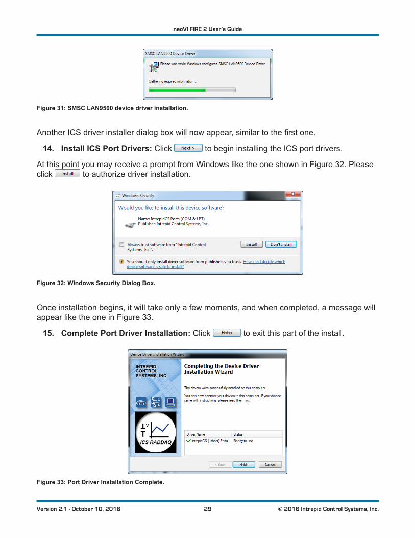
Once installation begins, it will take only a few moments, and when completed, a message will appear like the one in Figure 33.
15. Complete Port Driver Installation: Click to exit this part of the install.
Figure 33: Port Driver Installation Complete.
neoVI FIRE 2 User’s Guide
30 © 2016 Intrepid Control Systems, Inc.Version 2.1 - October 10, 2016
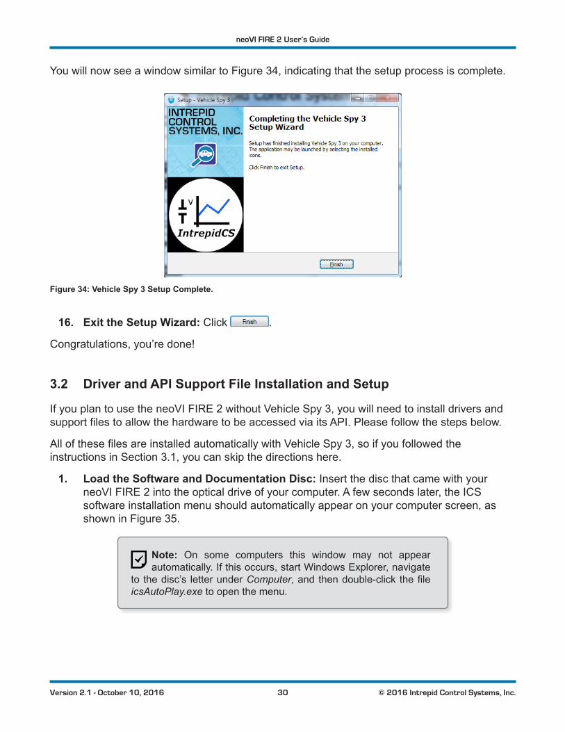
You will now see a window similar to Figure 34, indicating that the setup process is complete.
Figure 34: Vehicle Spy 3 Setup Complete.
16. Exit the Setup Wizard: Click .
Congratulations, you’re done!
3.2 Driver and API Support File Installation and Setup
If you plan to use the neoVI FIRE 2 without Vehicle Spy 3, you will need to install drivers and supportfilestoallowthehardwaretobeaccessedviaitsAPI.Pleasefollowthestepsbelow.
AllofthesefilesareinstalledautomaticallywithVehicleSpy3,soifyoufollowedtheinstructions in Section 3.1, you can skip the directions here.
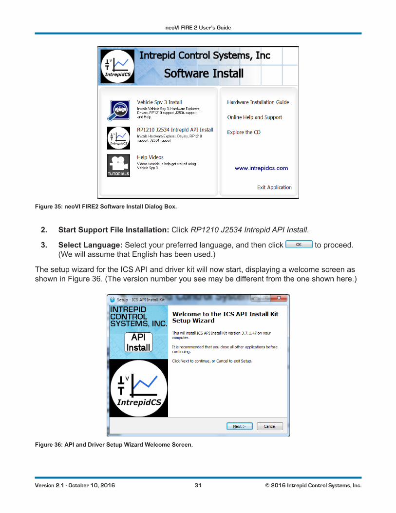
1. Load the Software and Documentation Disc: Insert the disc that came with your neoVI FIRE 2 into the optical drive of your computer. A few seconds later, the ICS software installation menu should automatically appear on your computer screen, as shown in Figure 35.
Note: On some computers this window may not appear automatically. If this occurs, start Windows Explorer, navigate
to the disc’s letter under Computer,andthendouble-click thefileicsAutoPlay.exe to open the menu.
neoVI FIRE 2 User’s Guide
31 © 2016 Intrepid Control Systems, Inc.Version 2.1 - October 10, 2016
Figure 35: neoVI FIRE2 Software Install Dialog Box.
2. Start Support File Installation: Click RP1210 J2534 Intrepid API Install.
3. Select Language: Select your preferred language, and then click to proceed. (We will assume that English has been used.)
The setup wizard for the ICS API and driver kit will now start, displaying a welcome screen as shown in Figure 36. (The version number you see may be different from the one shown here.)
Figure 36: API and Driver Setup Wizard Welcome Screen.
neoVI FIRE 2 User’s Guide
32 © 2016 Intrepid Control Systems, Inc.Version 2.1 - October 10, 2016
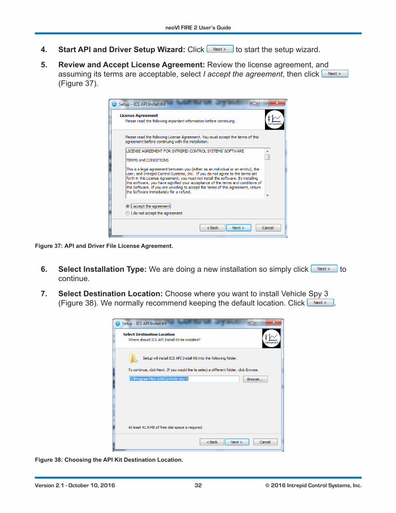
4. Start API and Driver Setup Wizard: Click to start the setup wizard.
5. Review and Accept License Agreement: Review the license agreement, and assuming its terms are acceptable, select I accept the agreement, then click (Figure 37).
Figure 37: API and Driver File License Agreement.
6. Select Installation Type: We are doing a new installation so simply click to continue.
7. Select Destination Location: Choose where you want to install Vehicle Spy 3 (Figure 38). We normally recommend keeping the default location. Click .
Figure 38: Choosing the API Kit Destination Location.
neoVI FIRE 2 User’s Guide
33 © 2016 Intrepid Control Systems, Inc.Version 2.1 - October 10, 2016
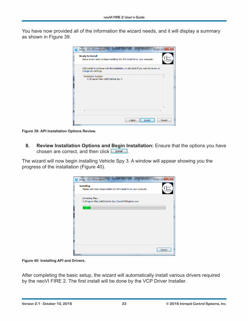
You have now provided all of the information the wizard needs, and it will display a summary as shown in Figure 39.
Figure 39: API Installation Options Review.
8. Review Installation Options and Begin Installation: Ensure that the options you have chosen are correct, and then click .
The wizard will now begin installing Vehicle Spy 3. A window will appear showing you the progress of the installation (Figure 40).
Figure 40: Installing API and Drivers.
After completing the basic setup, the wizard will automatically install various drivers required bytheneoVIFIRE2.ThefirstinstallwillbedonebytheVCPDriverInstaller.
neoVI FIRE 2 User’s Guide
34 © 2016 Intrepid Control Systems, Inc.Version 2.1 - October 10, 2016
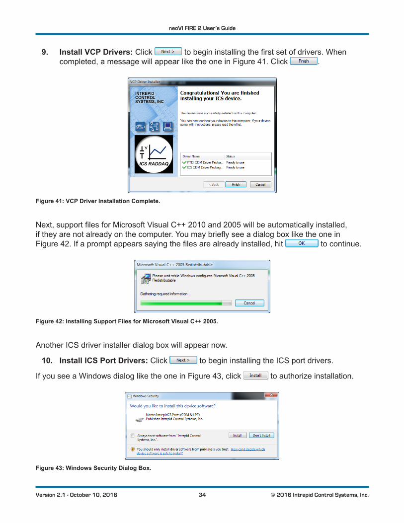
9. Install VCP Drivers: Click tobegininstallingthefirstsetofdrivers.Whencompleted, a message will appear like the one in Figure 41. Click .
Figure 41: VCP Driver Installation Complete.
Next,supportfilesforMicrosoftVisualC++2010and2005willbeautomaticallyinstalled,iftheyarenotalreadyonthecomputer.YoumaybrieflyseeadialogboxliketheoneinFigure 42.Ifapromptappearssayingthefilesarealreadyinstalled,hit to continue.
Figure 42: Installing Support Files for Microsoft Visual C++ 2005.
Another ICS driver installer dialog box will appear now.
10. Install ICS Port Drivers: Click to begin installing the ICS port drivers.
If you see a Windows dialog like the one in Figure 43, click to authorize installation.
Figure 43: Windows Security Dialog Box.
neoVI FIRE 2 User’s Guide
35 © 2016 Intrepid Control Systems, Inc.Version 2.1 - October 10, 2016
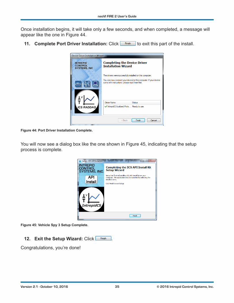
Once installation begins, it will take only a few seconds, and when completed, a message will appear like the one in Figure 44.
11. Complete Port Driver Installation: Click to exit this part of the install.
Figure 44: Port Driver Installation Complete.
You will now see a dialog box like the one shown in Figure 45, indicating that the setup process is complete.
Figure 45: Vehicle Spy 3 Setup Complete.
12. Exit the Setup Wizard: Click .
Congratulations, you’re done!
neoVI FIRE 2 User’s Guide
36 © 2016 Intrepid Control Systems, Inc.Version 2.1 - October 10, 2016
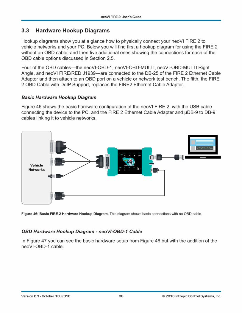
3.3 Hardware Hookup Diagrams
Hookup diagrams show you at a glance how to physically connect your neoVI FIRE 2 to vehiclenetworksandyourPC.BelowyouwillfindfirstahookupdiagramforusingtheFIRE2withoutanOBDcable,andthenfiveadditionalonesshowingtheconnectionsforeachoftheOBD cable options discussed in Section 2.5.
Four of the OBD cables—the neoVI-OBD-1, neoVI-OBD-MULTI, neoVI-OBD-MULTI Right Angle, and neoVI FIRE/RED J1939—are connected to the DB-25 of the FIRE 2 Ethernet Cable AdapterandthenattachtoanOBDportonavehicleornetworktestbench.Thefifth,theFIRE2 OBD Cable with DoIP Support, replaces the FIRE2 Ethernet Cable Adapter.
Basic Hardware Hookup Diagram
Figure 46showsthebasichardwareconfigurationoftheneoVIFIRE2,withtheUSBcableconnecting the device to the PC, and the FIRE 2 Ethernet Cable Adapter and µDB-9 to DB-9 cables linking it to vehicle networks.
VehicleNetworks
Figure 46: Basic FIRE 2 Hardware Hookup Diagram. This diagram shows basic connections with no OBD cable.
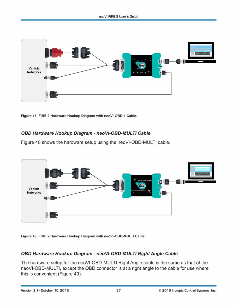
OBD Hardware Hookup Diagram - neoVI-OBD-1 Cable
In Figure 47 you can see the basic hardware setup from Figure 46 but with the addition of the neoVI-OBD-1 cable.
neoVI FIRE 2 User’s Guide
37 © 2016 Intrepid Control Systems, Inc.Version 2.1 - October 10, 2016
VehicleNetworks
Figure 47: FIRE 2 Hardware Hookup Diagram with neoVI-OBD-1 Cable.
OBD Hardware Hookup Diagram - neoVI-OBD-MULTI Cable
Figure 48 shows the hardware setup using the neoVI-OBD-MULTI cable.
VehicleNetworks
Figure 48: FIRE 2 Hardware Hookup Diagram with neoVI-OBD-MULTI Cable.
OBD Hardware Hookup Diagram - neoVI-OBD-MULTI Right Angle Cable
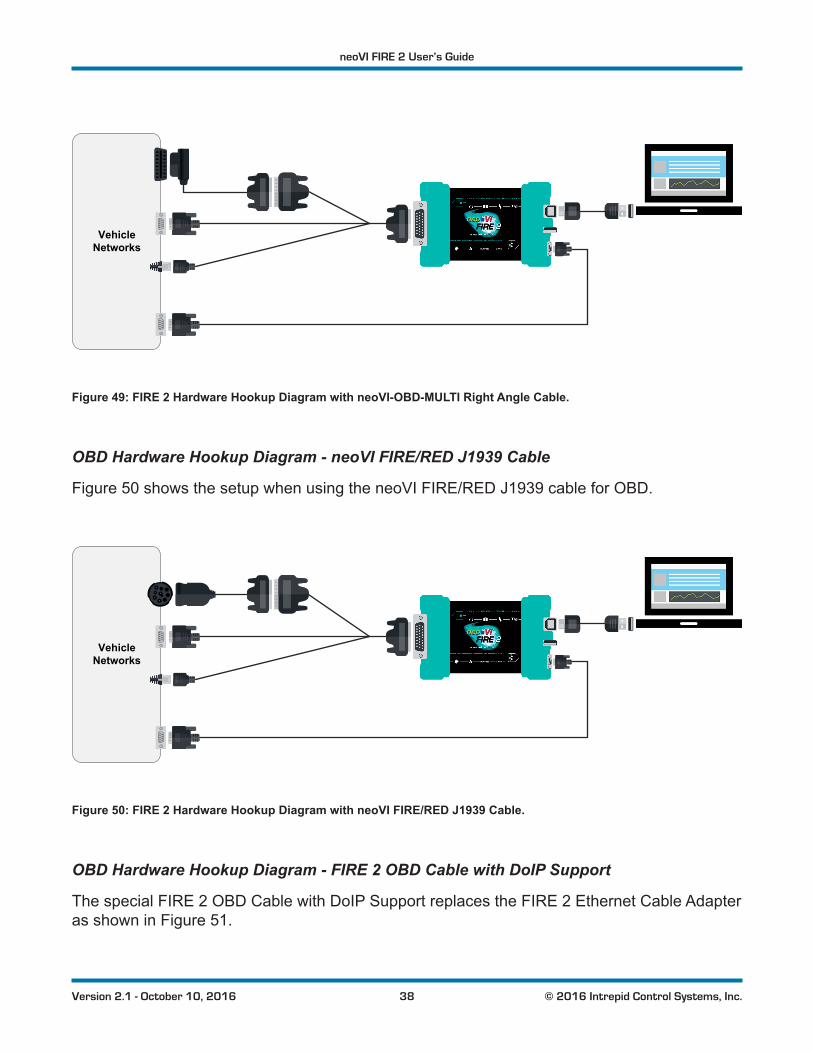
The hardware setup for the neoVI-OBD-MULTI Right Angle cable is the same as that of the neoVI-OBD-MULTI, except the OBD connector is at a right angle to the cable for use where this is convenient (Figure 49).
neoVI FIRE 2 User’s Guide
38 © 2016 Intrepid Control Systems, Inc.Version 2.1 - October 10, 2016
VehicleNetworks
Figure 49: FIRE 2 Hardware Hookup Diagram with neoVI-OBD-MULTI Right Angle Cable.
OBD Hardware Hookup Diagram - neoVI FIRE/RED J1939 Cable
Figure 50 shows the setup when using the neoVI FIRE/RED J1939 cable for OBD.
VehicleNetworks
Figure 50: FIRE 2 Hardware Hookup Diagram with neoVI FIRE/RED J1939 Cable.
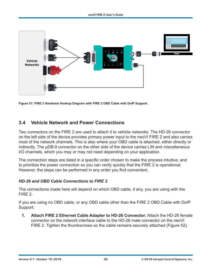
OBD Hardware Hookup Diagram - FIRE 2 OBD Cable with DoIP Support
The special FIRE 2 OBD Cable with DoIP Support replaces the FIRE 2 Ethernet Cable Adapter as shown in Figure 51.
neoVI FIRE 2 User’s Guide
39 © 2016 Intrepid Control Systems, Inc.Version 2.1 - October 10, 2016
VehicleNetworks
Figure 51: FIRE 2 Hardware Hookup Diagram with FIRE 2 OBD Cable with DoIP Support.
3.4 Vehicle Network and Power Connections
Two connectors on the FIRE 2 are used to attach it to vehicle networks. The HD-26 connector on the left side of the device provides primary power input to the neoVI FIRE 2 and also carries most of the network channels. This is also where your OBD cable is attached, either directly or indirectly. The µDB-9 connector on the other side of the device carries LIN and miscellaneous I/O channels, which you may or may not need depending on your application.
Theconnectionstepsarelistedinaspecificorderchosentomaketheprocessintuitive,andto prioritize the power connection so you can verify quickly that the FIRE 2 is operational. However,thestepscanbeperformedinanyorderyoufindconvenient.
HD-26 and OBD Cable Connections to FIRE 2
The connections made here will depend on which OBD cable, if any, you are using with the FIRE 2.
If you are using no OBD cable, or any OBD cable other than the FIRE 2 OBD Cable with DoIP Support:
1. Attach FIRE 2 Ethernet Cable Adapter to HD-26 Connector: Attach the HD-26 female connector on the network interface cable to the HD-26 male connector on the neoVI FIRE 2. Tighten the thumbscrews so the cable remains securely attached (Figure 52).
neoVI FIRE 2 User’s Guide
40 © 2016 Intrepid Control Systems, Inc.Version 2.1 - October 10, 2016
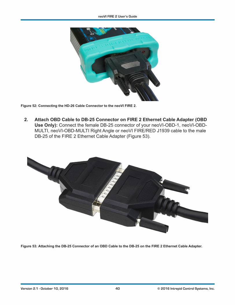
Figure 52: Connecting the HD-26 Cable Connector to the neoVI FIRE 2.
2. Attach OBD Cable to DB-25 Connector on FIRE 2 Ethernet Cable Adapter (OBD Use Only): Connect the female DB-25 connector of your neoVI-OBD-1, neoVI-OBD-MULTI, neoVI-OBD-MULTI Right Angle or neoVI FIRE/RED J1939 cable to the male DB-25 of the FIRE 2 Ethernet Cable Adapter (Figure 53).
Figure 53: Attaching the DB-25 Connector of an OBD Cable to the DB-25 on the FIRE 2 Ethernet Cable Adapter.
neoVI FIRE 2 User’s Guide
41 © 2016 Intrepid Control Systems, Inc.Version 2.1 - October 10, 2016
3. Attach DB-25, DB-9, RJ-45, J1939 and/or OBD-II Connectors to Vehicle Network: Attach the connectors from the FIRE 2 Ethernet Cable Adapter and your OBD cable (if using) to their mating halves on your network, then secure them in place.
As soon as you connect the device supplying power to the cable attached to the neoVI FIRE 2, thedeviceshouldbootup.YouwillrecognizethisbygreenLEDsbeginningtoflashinaquickand regular pattern on both the side of the device next to the HD-26 connection, and in the upperleftcornerofthetopmembraneinterface.IftheLEDsdonotstartflashing,pleaseseeChapter 8 for assistance.
µDB-9 to DB-9 Cable Connection to FIRE 2
We’ll now continue with the µDB-9 connector on the other side of the FIRE 2, using the special µDB-9 to DB-9 cable that comes with the device. This connection carries LIN and miscellaneous I/O channels for networks that require them; if they are not relevant to you, the next two steps can be skipped.
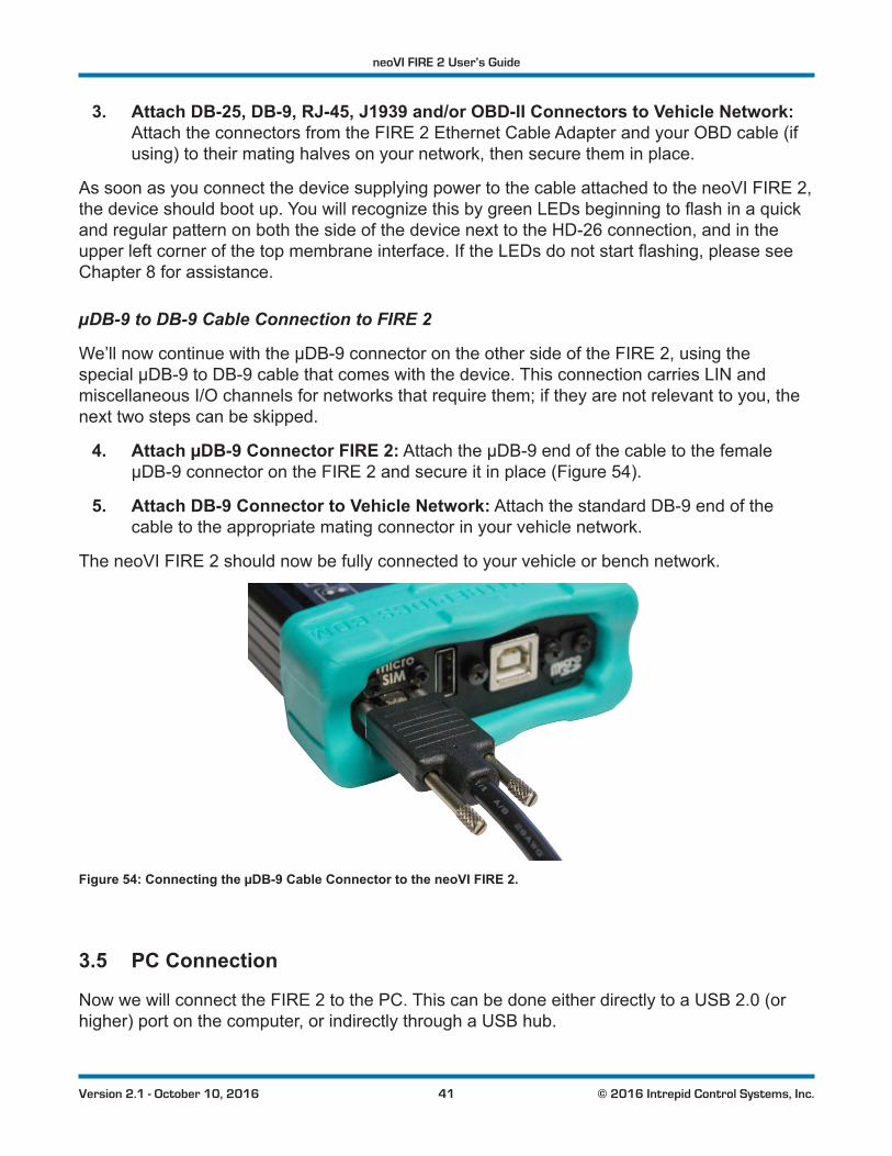
4. Attach µDB-9 Connector FIRE 2: Attach the µDB-9 end of the cable to the female µDB-9 connector on the FIRE 2 and secure it in place (Figure 54).
5. Attach DB-9 Connector to Vehicle Network: Attach the standard DB-9 end of the cable to the appropriate mating connector in your vehicle network.
The neoVI FIRE 2 should now be fully connected to your vehicle or bench network.
Figure 54: Connecting the µDB-9 Cable Connector to the neoVI FIRE 2.
3.5 PC Connection
Now we will connect the FIRE 2 to the PC. This can be done either directly to a USB 2.0 (or higher) port on the computer, or indirectly through a USB hub.
neoVI FIRE 2 User’s Guide
42 © 2016 Intrepid Control Systems, Inc.Version 2.1 - October 10, 2016
The neoVI FIRE 2 can draw up to the USB standard maximum of 500 mA through its USB connection. All computers should be able to supply this amount of current, however, unpowered USB hubs may not be able to do so, especially if they have multiple devices connectedtothem.IfyouexperiencedifficultieswiththeFIRE2whenusinganunpoweredhub port, but the device works when connected directly to a PC USB slot, you probably need to use the PC slot or a powered hub.
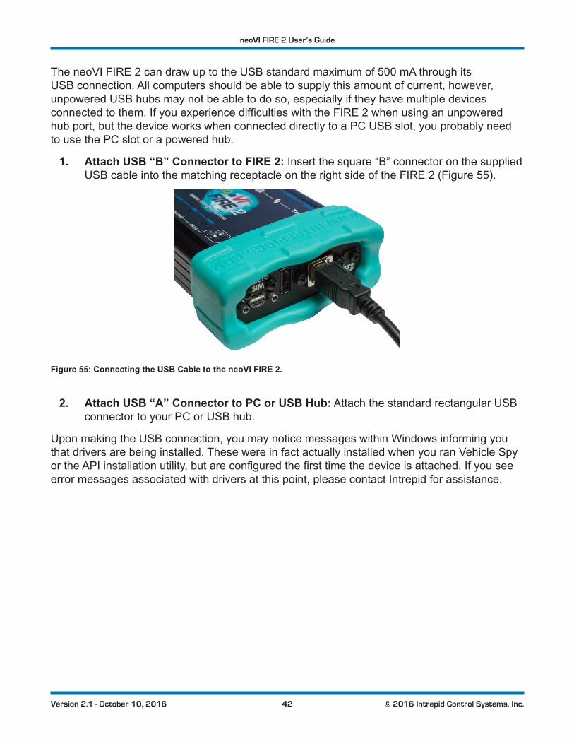
1. Attach USB “B” Connector to FIRE 2: Insert the square “B” connector on the supplied USB cable into the matching receptacle on the right side of the FIRE 2 (Figure 55).
Figure 55: Connecting the USB Cable to the neoVI FIRE 2.
2. Attach USB “A” Connector to PC or USB Hub: Attach the standard rectangular USB connector to your PC or USB hub.
Upon making the USB connection, you may notice messages within Windows informing you that drivers are being installed. These were in fact actually installed when you ran Vehicle Spy ortheAPIinstallationutility,butareconfiguredthefirsttimethedeviceisattached.Ifyouseeerror messages associated with drivers at this point, please contact Intrepid for assistance.
neoVI FIRE 2 User’s Guide
43 © 2016 Intrepid Control Systems, Inc.Version 2.1 - October 10, 2016
4 Device ConfigurationYour neoVI FIRE 2 ships from the factory ready to use with its default settings. However, its operation can also be customized to your exact needs by adjusting dozens of parameters that controlitsinternalhardwareandfirmware.Inthischapter,we’llshowyouhowtomanageandfine-tuneyourneoVIFIRE2,includingenablinganddisablingnetworks,adjustingbaudrates,turningonoroffspecificfeatures,andmuchmore.
4.1 Starting and Using neoVI Explorer
The neoVI Explorerutilityallowsyoutoconnectto,manageandconfigureallofyourIntrepidControl Systems hardware, including the neoVI FIRE 2. It is supplied both as an integrated feature of Vehicle Spy, and as a standalone program.
This section will describe general features and the basics of using neoVI Explorer, so you will understandtheutilitywellwhenwegetintosettingsspecifictotheFIRE2.
Starting neoVI Explorer from within Vehicle Spy
There are several ways to open neoVI Explorer from within VSpy. These are probably the two easiest, since they are accessible at all times:
• Menu Item: Click the Setup menu and then select Hardware.
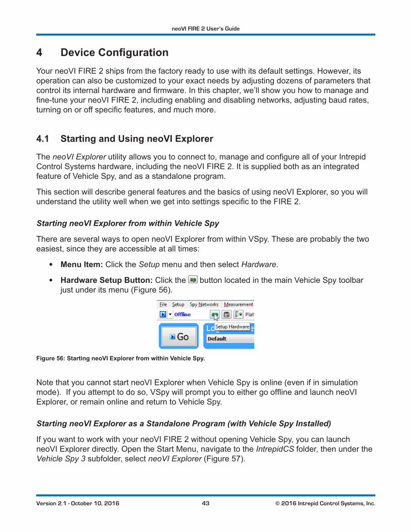
• Hardware Setup Button: Click the button located in the main Vehicle Spy toolbar just under its menu (Figure 56).
Figure 56: Starting neoVI Explorer from within Vehicle Spy.
Note that you cannot start neoVI Explorer when Vehicle Spy is online (even if in simulation mode).Ifyouattempttodoso,VSpywillpromptyoutoeithergoofflineandlaunchneoVIExplorer, or remain online and return to Vehicle Spy.
Starting neoVI Explorer as a Standalone Program (with Vehicle Spy Installed)
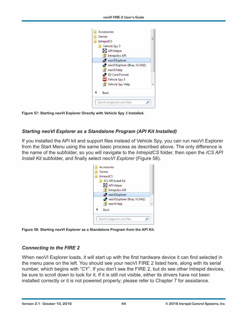
If you want to work with your neoVI FIRE 2 without opening Vehicle Spy, you can launch neoVI Explorer directly. Open the Start Menu, navigate to the IntrepidCS folder, then under the Vehicle Spy 3 subfolder, select neoVI Explorer (Figure 57).
neoVI FIRE 2 User’s Guide
44 © 2016 Intrepid Control Systems, Inc.Version 2.1 - October 10, 2016
Figure 57: Starting neoVI Explorer Directly with Vehicle Spy 3 Installed.
Starting neoVI Explorer as a Standalone Program (API Kit Installed)
IfyouinstalledtheAPIkitandsupportfilesinsteadofVehicleSpy,youcanrunneoVIExplorerfrom the Start Menu using the same basic process as described above. The only difference is the name of the subfolder, so you will navigate to the IntrepidCS folder, then open the ICS API Install Kitsubfolder,andfinallyselectneoVI Explorer (Figure 58).
Figure 58: Starting neoVI Explorer as a Standalone Program from the API Kit.
Connecting to the FIRE 2
WhenneoVIExplorerloads,itwillstartupwiththefirsthardwaredeviceitcanfindselectedinthe menu pane on the left. You should see your neoVI FIRE 2 listed here, along with its serial number, which begins with “CY”. If you don’t see the FIRE 2, but do see other Intrepid devices, be sure to scroll down to look for it. If it is still not visible, either its drivers have not been installed correctly or it is not powered properly; please refer to Chapter 7 for assistance.
neoVI FIRE 2 User’s Guide
45 © 2016 Intrepid Control Systems, Inc.Version 2.1 - October 10, 2016
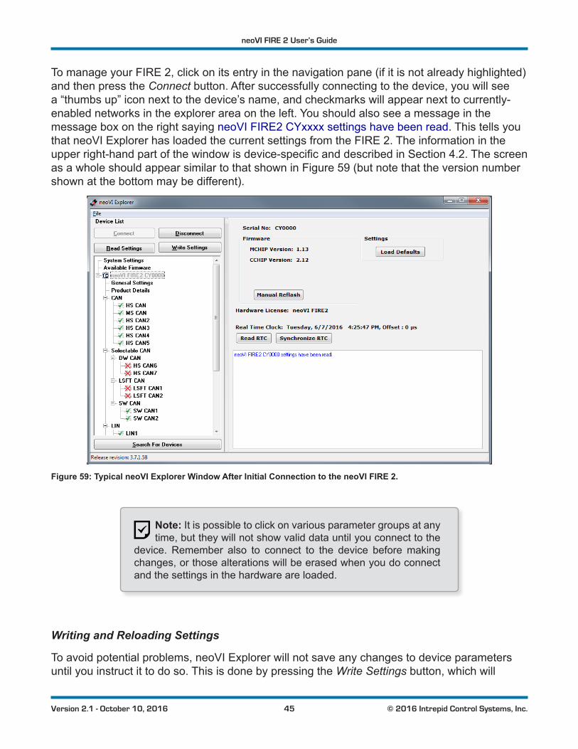
To manage your FIRE 2, click on its entry in the navigation pane (if it is not already highlighted) and then press the Connect button. After successfully connecting to the device, you will see a “thumbs up” icon next to the device’s name, and checkmarks will appear next to currently-enabled networks in the explorer area on the left. You should also see a message in the message box on the right saying neoVI FIRE2 CYxxxx settings have been read. This tells you that neoVI Explorer has loaded the current settings from the FIRE 2. The information in the upperright-handpartofthewindowisdevice-specificanddescribedinSection 4.2. The screen as a whole should appear similar to that shown in Figure 59 (but note that the version number shown at the bottom may be different).
Figure 59: Typical neoVI Explorer Window After Initial Connection to the neoVI FIRE 2.
Note: It is possible to click on various parameter groups at any time, but they will not show valid data until you connect to the
device. Remember also to connect to the device before making changes, or those alterations will be erased when you do connect and the settings in the hardware are loaded.
Writing and Reloading Settings
To avoid potential problems, neoVI Explorer will not save any changes to device parameters until you instruct it to do so. This is done by pressing the Write Settings button, which will
neoVI FIRE 2 User’s Guide
46 © 2016 Intrepid Control Systems, Inc.Version 2.1 - October 10, 2016
updatetheparameterswithinthefirmwareinyourFIRE2.Ifyoumakechangesyoudonotwant to keep, pressing the Read Settings button will reload the settings stored in the device, wipingoutanymodificationsmadeinneoVIExplorerthathadnotyetbeensaved.
Reloading Device Defaults
To return all settings to factory defaults, press the Load Defaults button. This is convenient if manychangeshavebeenmadeandwrittentothefirmwareinthepast,andyouwanttostartover with a clean slate.
Notethatpressingthisbuttonactuallywritesthedefaultstothedevicefirst,andthenreloadsthem automatically, so you do not need to also press Write Settings. You will see messages in the message area telling you that defaults have been sent to the device and then read from it.
Disconnecting from the FIRE 2
Press the Disconnect button to tell neoVI Explorer that you are done working with the FIRE 2. This step is actually optional, because neoVI Explorer will disconnect from any connected devices when you exit the program.
Searching for Devices
If you attach new hardware to your PC after starting neoVI Explorer, press the Search For Devices button at the bottom left of the dialog box to prompt the program to scan for new hardware you can manage.
Exiting neoVI Explorer
Like any Windows program, you can close neoVI Explorer by clicking the “X” in the top right corner, or pressing the Alt+F4 key combination.
4.2 System Settings and Firmware Updates
The top two entries in the explorer window on the left side of neoVI Explorer contain system-widesettingsthatapplytoallhardwaredevices,andinformationrelatedtofirmwareupdates.
System Settings
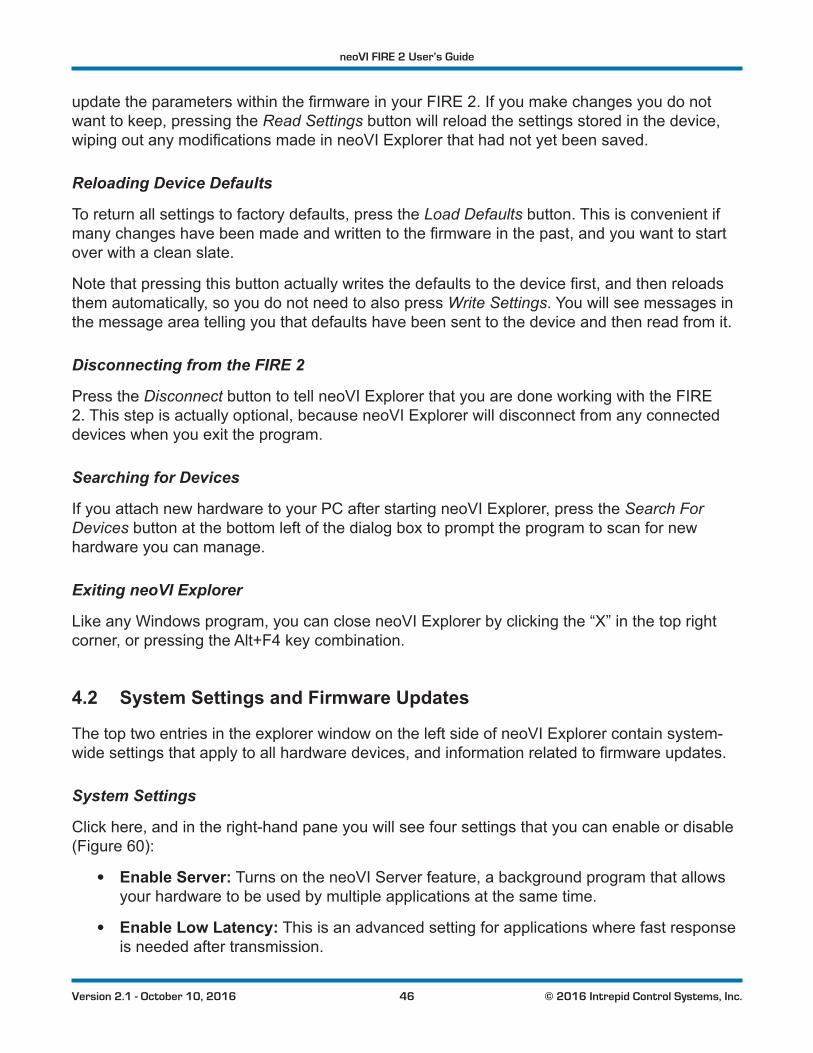
Click here, and in the right-hand pane you will see four settings that you can enable or disable (Figure 60):
• Enable Server: Turns on the neoVI Server feature, a background program that allows your hardware to be used by multiple applications at the same time.
• Enable Low Latency: This is an advanced setting for applications where fast response is needed after transmission.
neoVI FIRE 2 User’s Guide
47 © 2016 Intrepid Control Systems, Inc.Version 2.1 - October 10, 2016
• Enable Slave VNET Settings: This setting is used for the FIRE 2 VNet module used with a neoVI Plasma or Ion, and can be ignored for the neoVI FIRE 2.
• Enable Auto Update: When enabled, both neoVI Explorer and Vehicle Spy will automaticallyupdatefirmware.Ifthisboxisnotchecked,firmwaremustbeupdatedmanually. (See below for details.)
Figure 60: neoVI Explorer System Settings Pane
Available Firmware
ThisisaninformationalpagethatshowswhichfirmwareversionsareavailableinthisversionofneoVIExplorerforvariousIntrepidproducts.Somedeviceshavemultiplefirmwareprogramsthat control different aspects of their operation; in the case of the FIRE 2, these are called MCHIP and CCHIP.
You normally won’t need to look in this area, because as we’ll see in Section 4.3, neoVI ExplorershowsyouthecurrentandavailablefirmwareversionsforyourFIRE2whenyouconnect to it.
Updating Firmware
Firmware is essentially software that runs hardware, and is required to enable the many capabilitiesofyourneoVIFIRE2.NewversionsoffirmwarearecreatedregularlybyIntrepid’sengineerstoimplementnewfeaturesandcorrectproblemsthathavebeenidentified.
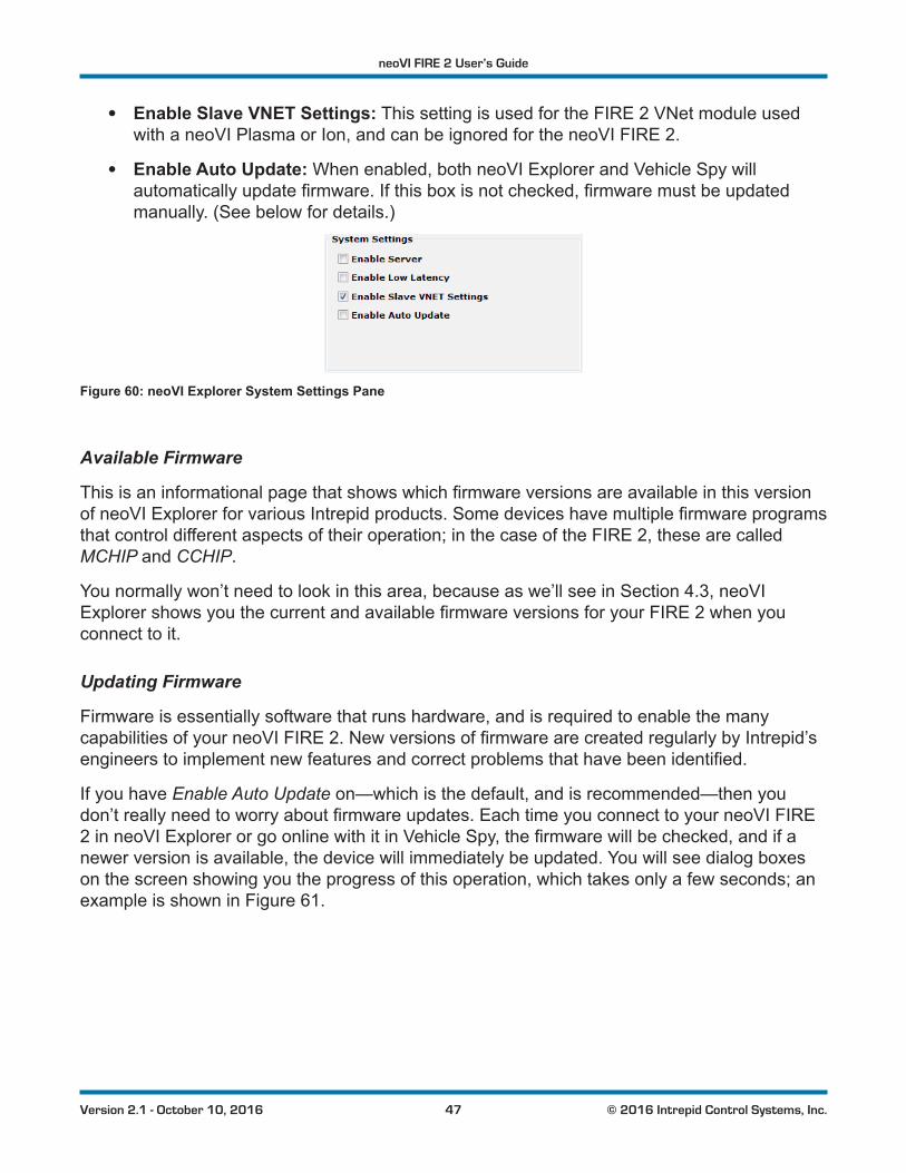
If you have Enable Auto Update on—which is the default, and is recommended—then you don’treallyneedtoworryaboutfirmwareupdates.EachtimeyouconnecttoyourneoVIFIRE2inneoVIExplorerorgoonlinewithitinVehicleSpy,thefirmwarewillbechecked,andifanewer version is available, the device will immediately be updated. You will see dialog boxes on the screen showing you the progress of this operation, which takes only a few seconds; an example is shown in Figure 61.
neoVI FIRE 2 User’s Guide
48 © 2016 Intrepid Control Systems, Inc.Version 2.1 - October 10, 2016
Figure 61: Firmware Download Message Box.
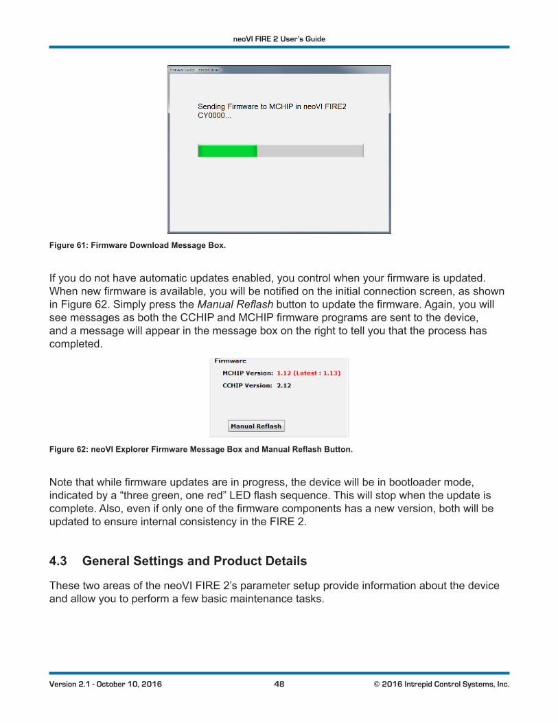
Ifyoudonothaveautomaticupdatesenabled,youcontrolwhenyourfirmwareisupdated.Whennewfirmwareisavailable,youwillbenotifiedontheinitialconnectionscreen,asshownin Figure 62. Simply press the Manual Reflashbuttontoupdatethefirmware.Again,youwillseemessagesasboththeCCHIPandMCHIPfirmwareprogramsaresenttothedevice,and a message will appear in the message box on the right to tell you that the process has completed.
Figure 62: neoVI Explorer Firmware Message Box and Manual Reflash Button.
Notethatwhilefirmwareupdatesareinprogress,thedevicewillbeinbootloadermode,indicatedbya“threegreen,onered”LEDflashsequence.Thiswillstopwhentheupdateiscomplete.Also,evenifonlyoneofthefirmwarecomponentshasanewversion,bothwillbeupdated to ensure internal consistency in the FIRE 2.
4.3 General Settings and Product Details
These two areas of the neoVI FIRE 2’s parameter setup provide information about the device and allow you to perform a few basic maintenance tasks.
neoVI FIRE 2 User’s Guide
49 © 2016 Intrepid Control Systems, Inc.Version 2.1 - October 10, 2016
General Settings
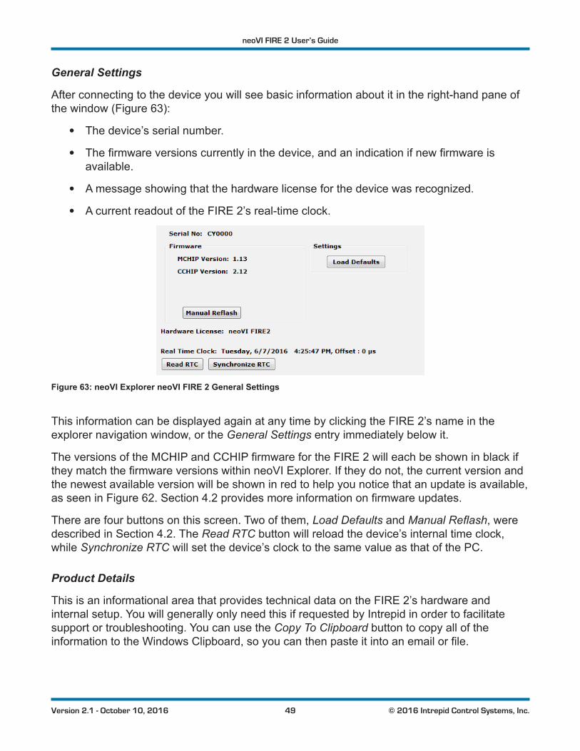
After connecting to the device you will see basic information about it in the right-hand pane of the window (Figure 63):
• The device’s serial number.
• Thefirmwareversionscurrentlyinthedevice,andanindicationifnewfirmwareisavailable.
• A message showing that the hardware license for the device was recognized.
• A current readout of the FIRE 2’s real-time clock.
Figure 63: neoVI Explorer neoVI FIRE 2 General Settings
This information can be displayed again at any time by clicking the FIRE 2’s name in the explorer navigation window, or the General Settings entry immediately below it.
TheversionsoftheMCHIPandCCHIPfirmwarefortheFIRE2willeachbeshowninblackiftheymatchthefirmwareversionswithinneoVIExplorer.Iftheydonot,thecurrentversionandthe newest available version will be shown in red to help you notice that an update is available, as seen in Figure 62. Section 4.2providesmoreinformationonfirmwareupdates.
There are four buttons on this screen. Two of them, Load Defaults and Manual Reflash, were described in Section 4.2. The Read RTC button will reload the device’s internal time clock, while Synchronize RTC will set the device’s clock to the same value as that of the PC.
Product Details
This is an informational area that provides technical data on the FIRE 2’s hardware and internal setup. You will generally only need this if requested by Intrepid in order to facilitate support or troubleshooting. You can use the Copy To Clipboard button to copy all of the informationtotheWindowsClipboard,soyoucanthenpasteitintoanemailorfile.
neoVI FIRE 2 User’s Guide
50 © 2016 Intrepid Control Systems, Inc.Version 2.1 - October 10, 2016
4.4 Standard CAN Networks (HS CAN 1-5 and MS CAN)
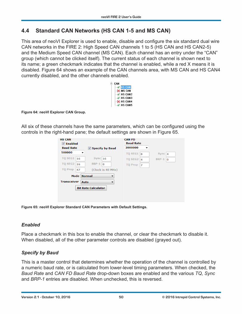
ThisareaofneoVIExplorerisusedtoenable,disableandconfigurethesixstandarddualwireCAN networks in the FIRE 2: High Speed CAN channels 1 to 5 (HS CAN and HS CAN2-5) and the Medium Speed CAN channel (MS CAN). Each channel has an entry under the “CAN” group (which cannot be clicked itself). The current status of each channel is shown next to its name; a green checkmark indicates that the channel is enabled, while a red X means it is disabled. Figure 64 shows an example of the CAN channels area, with MS CAN and HS CAN4 currently disabled, and the other channels enabled.
Figure 64: neoVI Explorer CAN Group.
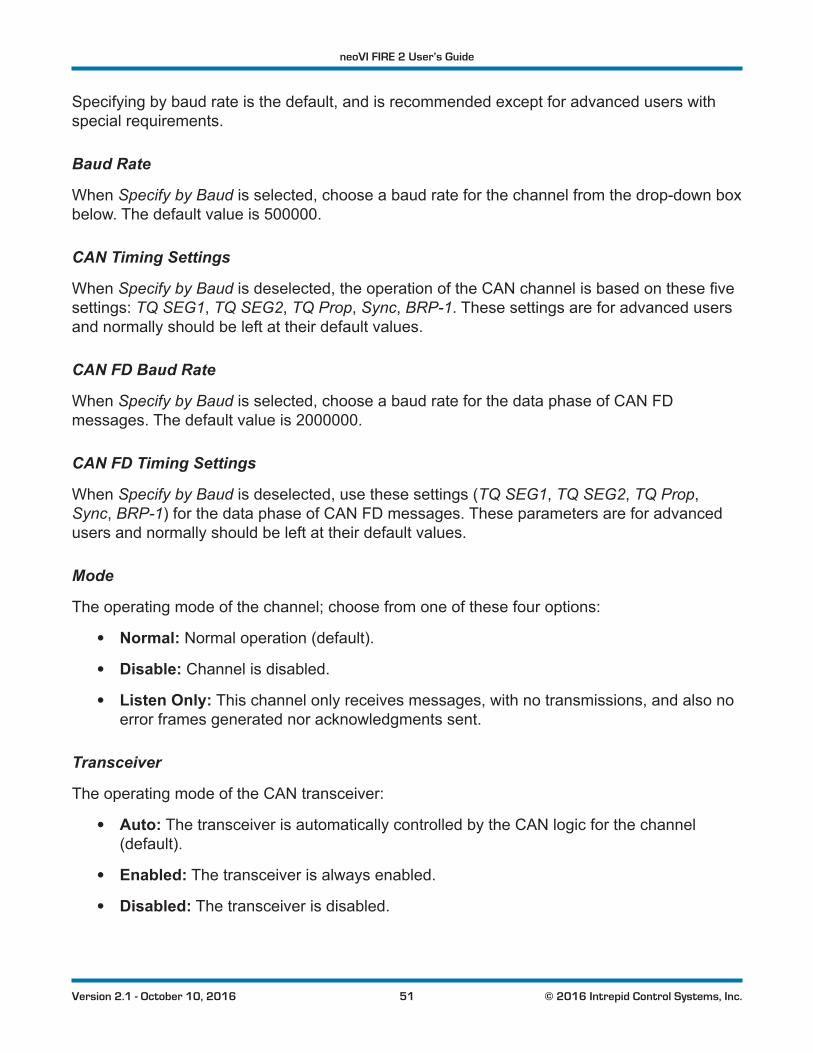
Allsixofthesechannelshavethesameparameters,whichcanbeconfiguredusingthecontrols in the right-hand pane; the default settings are shown in Figure 65.
Figure 65: neoVI Explorer Standard CAN Parameters with Default Settings.
Enabled
Place a checkmark in this box to enable the channel, or clear the checkmark to disable it. When disabled, all of the other parameter controls are disabled (grayed out).
Specify by Baud
This is a master control that determines whether the operation of the channel is controlled by a numeric baud rate, or is calculated from lower-level timing parameters. When checked, the Baud Rate and CAN FD Baud Rate drop-down boxes are enabled and the various TQ, Sync and BRP-1 entries are disabled. When unchecked, this is reversed.
neoVI FIRE 2 User’s Guide
51 © 2016 Intrepid Control Systems, Inc.Version 2.1 - October 10, 2016
Specifying by baud rate is the default, and is recommended except for advanced users with special requirements.
Baud Rate
When Specify by Baud is selected, choose a baud rate for the channel from the drop-down box below. The default value is 500000.
CAN Timing Settings
When Specify by Baudisdeselected,theoperationoftheCANchannelisbasedonthesefivesettings: TQ SEG1, TQ SEG2, TQ Prop, Sync, BRP-1. These settings are for advanced users and normally should be left at their default values.
CAN FD Baud Rate
When Specify by Baud is selected, choose a baud rate for the data phase of CAN FD messages. The default value is 2000000.
CAN FD Timing Settings
When Specify by Baud is deselected, use these settings (TQ SEG1, TQ SEG2, TQ Prop, Sync, BRP-1) for the data phase of CAN FD messages. These parameters are for advanced users and normally should be left at their default values.
Mode
The operating mode of the channel; choose from one of these four options:
• Normal: Normal operation (default).
• Disable: Channel is disabled.
• Listen Only: This channel only receives messages, with no transmissions, and also no error frames generated nor acknowledgments sent.
Transceiver
The operating mode of the CAN transceiver:
• Auto: The transceiver is automatically controlled by the CAN logic for the channel (default).
• Enabled: The transceiver is always enabled.
• Disabled: The transceiver is disabled.
neoVI FIRE 2 User’s Guide
52 © 2016 Intrepid Control Systems, Inc.Version 2.1 - October 10, 2016
Bit Rate Calculator
Press this button to launch the Intrepid Bit Timing Calculator.
4.5 Selectable CAN Networks
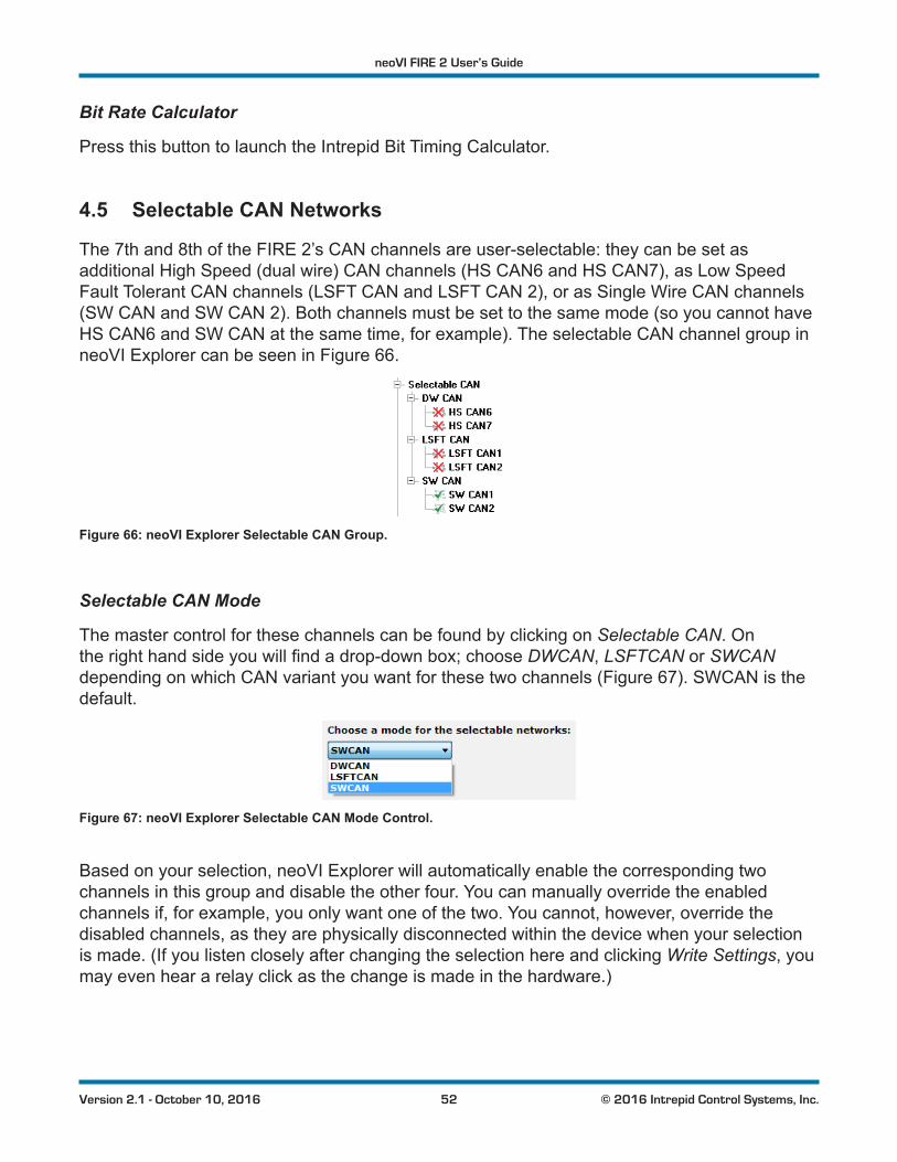
The 7th and 8th of the FIRE 2’s CAN channels are user-selectable: they can be set as additional High Speed (dual wire) CAN channels (HS CAN6 and HS CAN7), as Low Speed Fault Tolerant CAN channels (LSFT CAN and LSFT CAN 2), or as Single Wire CAN channels (SW CAN and SW CAN 2). Both channels must be set to the same mode (so you cannot have HS CAN6 and SW CAN at the same time, for example). The selectable CAN channel group in neoVI Explorer can be seen in Figure 66.
Figure 66: neoVI Explorer Selectable CAN Group.
Selectable CAN Mode
The master control for these channels can be found by clicking on Selectable CAN. On therighthandsideyouwillfindadrop-downbox;chooseDWCAN, LSFTCAN or SWCAN depending on which CAN variant you want for these two channels (Figure 67). SWCAN is the default.
Figure 67: neoVI Explorer Selectable CAN Mode Control.
Based on your selection, neoVI Explorer will automatically enable the corresponding two channels in this group and disable the other four. You can manually override the enabled channels if, for example, you only want one of the two. You cannot, however, override the disabled channels, as they are physically disconnected within the device when your selection is made. (If you listen closely after changing the selection here and clicking Write Settings, you may even hear a relay click as the change is made in the hardware.)
neoVI FIRE 2 User’s Guide
53 © 2016 Intrepid Control Systems, Inc.Version 2.1 - October 10, 2016
DW CAN (HS CAN 6 / HS CAN 7)
When DWCAN is selected, two additional High Speed CAN channels are turned on. Their parameters are identical to the six standard CAN channels described in Section 4.4, and are configuredinthesameway.
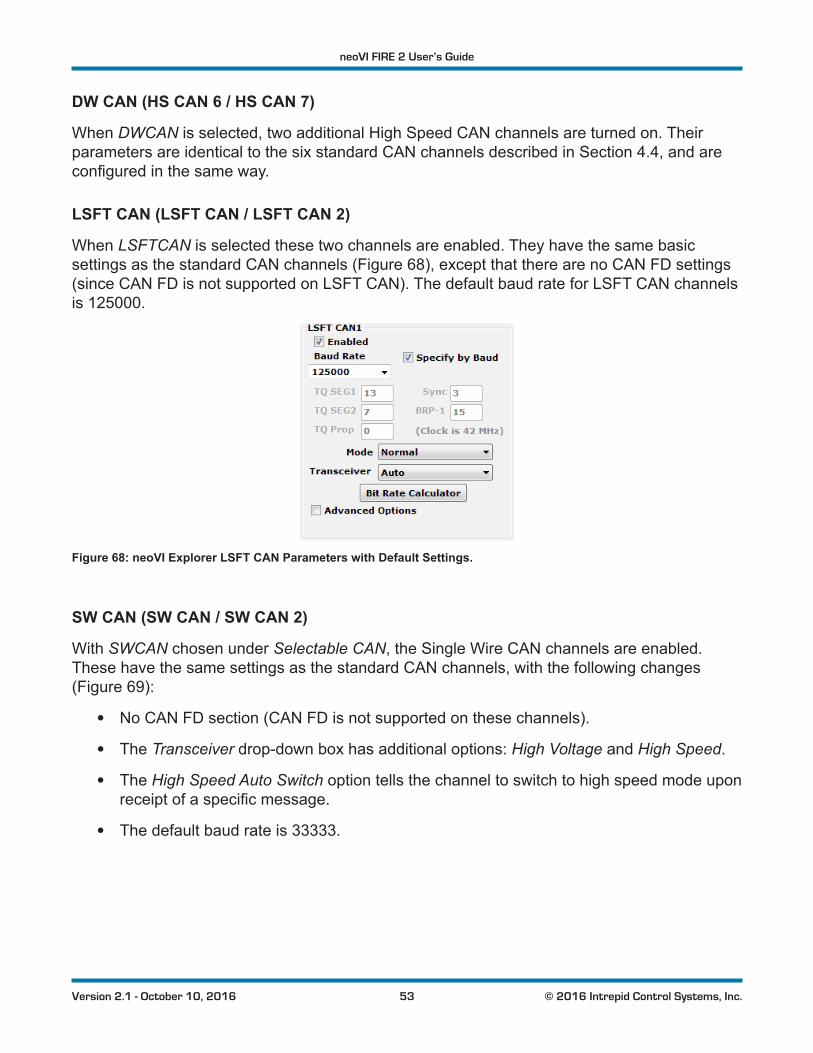
LSFT CAN (LSFT CAN / LSFT CAN 2)
When LSFTCAN is selected these two channels are enabled. They have the same basic settings as the standard CAN channels (Figure 68), except that there are no CAN FD settings (since CAN FD is not supported on LSFT CAN). The default baud rate for LSFT CAN channels is 125000.
Figure 68: neoVI Explorer LSFT CAN Parameters with Default Settings.
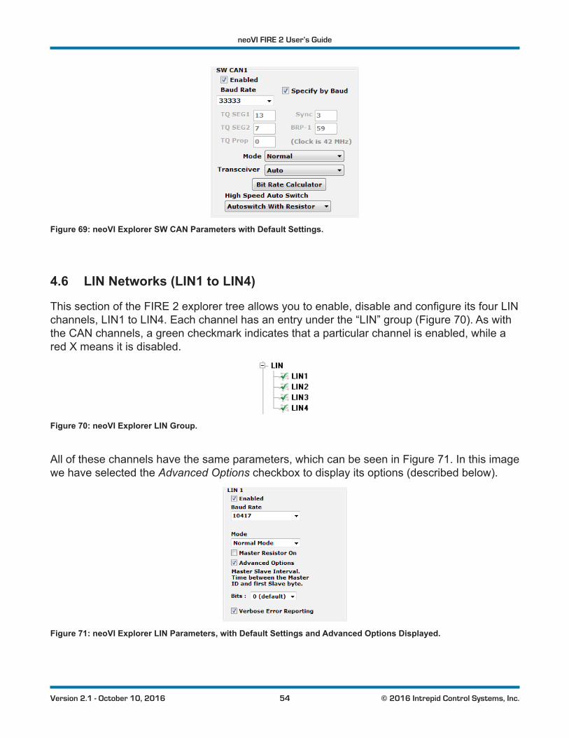
SW CAN (SW CAN / SW CAN 2)
With SWCAN chosen under Selectable CAN, the Single Wire CAN channels are enabled. These have the same settings as the standard CAN channels, with the following changes (Figure 69):
• No CAN FD section (CAN FD is not supported on these channels).
• The Transceiver drop-down box has additional options: High Voltage and High Speed.
• The High Speed Auto Switch option tells the channel to switch to high speed mode upon receiptofaspecificmessage.
• The default baud rate is 33333.
neoVI FIRE 2 User’s Guide
54 © 2016 Intrepid Control Systems, Inc.Version 2.1 - October 10, 2016
Figure 69: neoVI Explorer SW CAN Parameters with Default Settings.
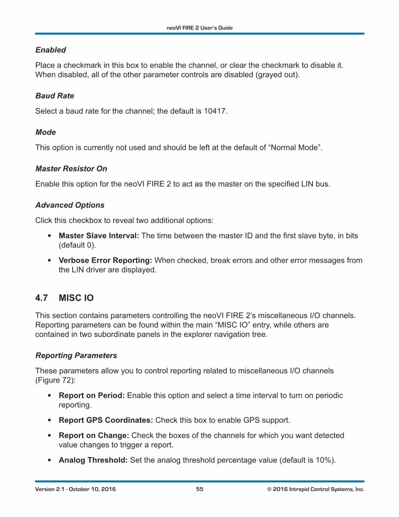
4.6 LIN Networks (LIN1 to LIN4)
ThissectionoftheFIRE2explorertreeallowsyoutoenable,disableandconfigureitsfourLINchannels, LIN1 to LIN4. Each channel has an entry under the “LIN” group (Figure 70). As with the CAN channels, a green checkmark indicates that a particular channel is enabled, while a red X means it is disabled.
Figure 70: neoVI Explorer LIN Group.
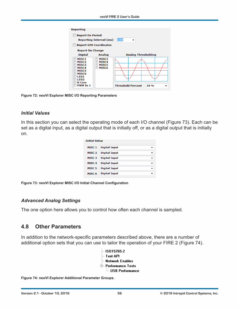
All of these channels have the same parameters, which can be seen in Figure 71. In this image we have selected the Advanced Options checkbox to display its options (described below).
Figure 71: neoVI Explorer LIN Parameters, with Default Settings and Advanced Options Displayed.
neoVI FIRE 2 User’s Guide
55 © 2016 Intrepid Control Systems, Inc.Version 2.1 - October 10, 2016
Enabled
Place a checkmark in this box to enable the channel, or clear the checkmark to disable it. When disabled, all of the other parameter controls are disabled (grayed out).
Baud Rate
Select a baud rate for the channel; the default is 10417.
Mode
This option is currently not used and should be left at the default of “Normal Mode”.
Master Resistor On
EnablethisoptionfortheneoVIFIRE2toactasthemasteronthespecifiedLINbus.
Advanced Options
Click this checkbox to reveal two additional options:
• Master Slave Interval:ThetimebetweenthemasterIDandthefirstslavebyte,inbits(default 0).
• Verbose Error Reporting: When checked, break errors and other error messages from the LIN driver are displayed.
4.7 MISC IO
This section contains parameters controlling the neoVI FIRE 2’s miscellaneous I/O channels. Reporting parameters can be found within the main “MISC IO” entry, while others are contained in two subordinate panels in the explorer navigation tree.
Reporting Parameters
These parameters allow you to control reporting related to miscellaneous I/O channels (Figure 72):
• Report on Period: Enable this option and select a time interval to turn on periodic reporting.
• Report GPS Coordinates: Check this box to enable GPS support.
• Report on Change: Check the boxes of the channels for which you want detected value changes to trigger a report.
• Analog Threshold: Set the analog threshold percentage value (default is 10%).
neoVI FIRE 2 User’s Guide
56 © 2016 Intrepid Control Systems, Inc.Version 2.1 - October 10, 2016
Figure 72: neoVI Explorer MISC I/O Reporting Parameters
Initial Values
In this section you can select the operating mode of each I/O channel (Figure 73). Each can be set as a digital input, as a digital output that is initially off, or as a digital output that is initially on.
Figure 73: neoVI Explorer MISC I/O Initial Channel Configuration
Advanced Analog Settings
The one option here allows you to control how often each channel is sampled.
4.8 Other Parameters
Inadditiontothenetwork-specificparametersdescribedabove,thereareanumberofadditional option sets that you can use to tailor the operation of your FIRE 2 (Figure 74).
Figure 74: neoVI Explorer Additional Parameter Groups.
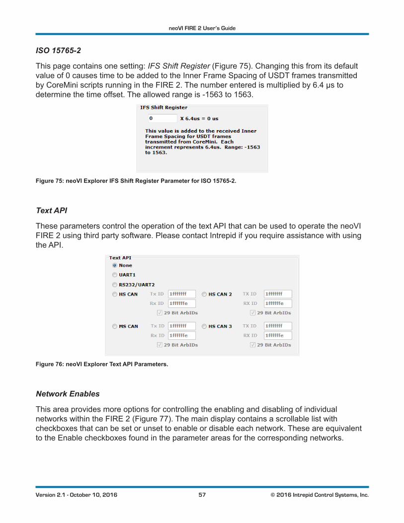
neoVI FIRE 2 User’s Guide
57 © 2016 Intrepid Control Systems, Inc.Version 2.1 - October 10, 2016
ISO 15765-2
This page contains one setting: IFS Shift Register (Figure 75). Changing this from its default value of 0 causes time to be added to the Inner Frame Spacing of USDT frames transmitted by CoreMini scripts running in the FIRE 2. The number entered is multiplied by 6.4 µs to determine the time offset. The allowed range is -1563 to 1563.
Figure 75: neoVI Explorer IFS Shift Register Parameter for ISO 15765-2.
Text API
These parameters control the operation of the text API that can be used to operate the neoVI FIRE 2 using third party software. Please contact Intrepid if you require assistance with using the API.
Figure 76: neoVI Explorer Text API Parameters.
Network Enables
This area provides more options for controlling the enabling and disabling of individual networks within the FIRE 2 (Figure 77). The main display contains a scrollable list with checkboxes that can be set or unset to enable or disable each network. These are equivalent to the Enable checkboxes found in the parameter areas for the corresponding networks.
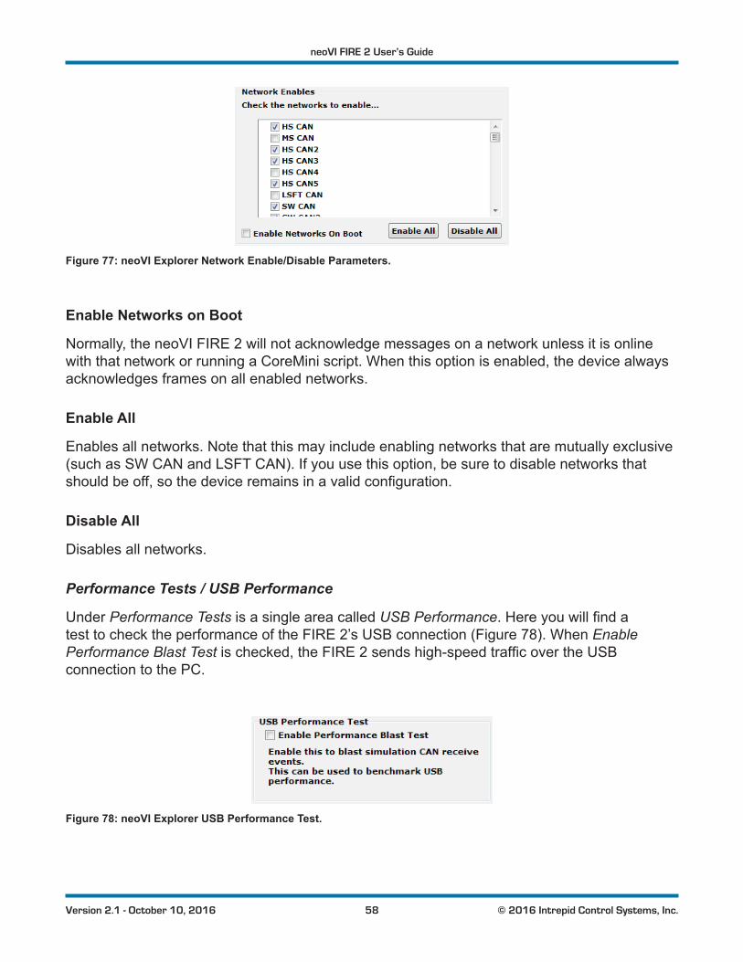
neoVI FIRE 2 User’s Guide
58 © 2016 Intrepid Control Systems, Inc.Version 2.1 - October 10, 2016
Figure 77: neoVI Explorer Network Enable/Disable Parameters.
Enable Networks on Boot
Normally, the neoVI FIRE 2 will not acknowledge messages on a network unless it is online with that network or running a CoreMini script. When this option is enabled, the device always acknowledges frames on all enabled networks.
Enable All
Enables all networks. Note that this may include enabling networks that are mutually exclusive (such as SW CAN and LSFT CAN). If you use this option, be sure to disable networks that shouldbeoff,sothedeviceremainsinavalidconfiguration.
Disable All
Disables all networks.
Performance Tests / USB Performance
Under Performance Tests is a single area called USB Performance.Hereyouwillfindatest to check the performance of the FIRE 2’s USB connection (Figure 78). When Enable Performance Blast Testischecked,theFIRE2sendshigh-speedtrafficovertheUSBconnection to the PC.
Figure 78: neoVI Explorer USB Performance Test.
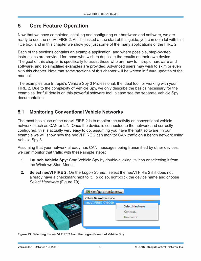
neoVI FIRE 2 User’s Guide
59 © 2016 Intrepid Control Systems, Inc.Version 2.1 - October 10, 2016
5 Core Feature OperationNowthatwehavecompletedinstallingandconfiguringourhardwareandsoftware,weareready to use the neoVI FIRE 2. As discussed at the start of this guide, you can do a lot with this little box, and in this chapter we show you just some of the many applications of the FIRE 2.
Each of the sections contains an example application, and where possible, step-by-step instructions are provided for those who wish to duplicate the results on their own device. ThegoalofthischapterisspecificallytoassistthosewhoarenewtoIntrepidhardwareandsoftware,andsosimplifiedexamplesareprovided.Advancedusersmaywishtoskimorevenskip this chapter. Note that some sections of this chapter will be written in future updates of the manual.
The examples use Intrepid’s Vehicle Spy 3 Professional, the ideal tool for working with your FIRE 2. Due to the complexity of Vehicle Spy, we only describe the basics necessary for the examples; for full details on this powerful software tool, please see the separate Vehicle Spy documentation.
5.1 Monitoring Conventional Vehicle Networks
The most basic use of the neoVI FIRE 2 is to monitor the activity on conventional vehicle networks such as CAN or LIN. Once the device is connected to the network and correctly configured,thisisactuallyveryeasytodo,assumingyouhavetherightsoftware.InourexamplewewillshowhowtheneoVIFIRE2canmonitorCANtrafficonabenchnetworkusingVehicle Spy 3.
Assuming that your network already has CAN messages being transmitted by other devices, wecanmonitorthattrafficwiththesesimplesteps:
1. Launch Vehicle Spy: Start Vehicle Spy by double-clicking its icon or selecting it from the Windows Start Menu.
2. Select neoVI FIRE 2: On the Logon Screen, select the neoVI FIRE 2 if it does not already have a checkmark next to it. To do so, right-click the device name and choose Select Hardware (Figure 79).
Figure 79: Selecting the neoVI FIRE 2 from the Logon Screen of Vehicle Spy.
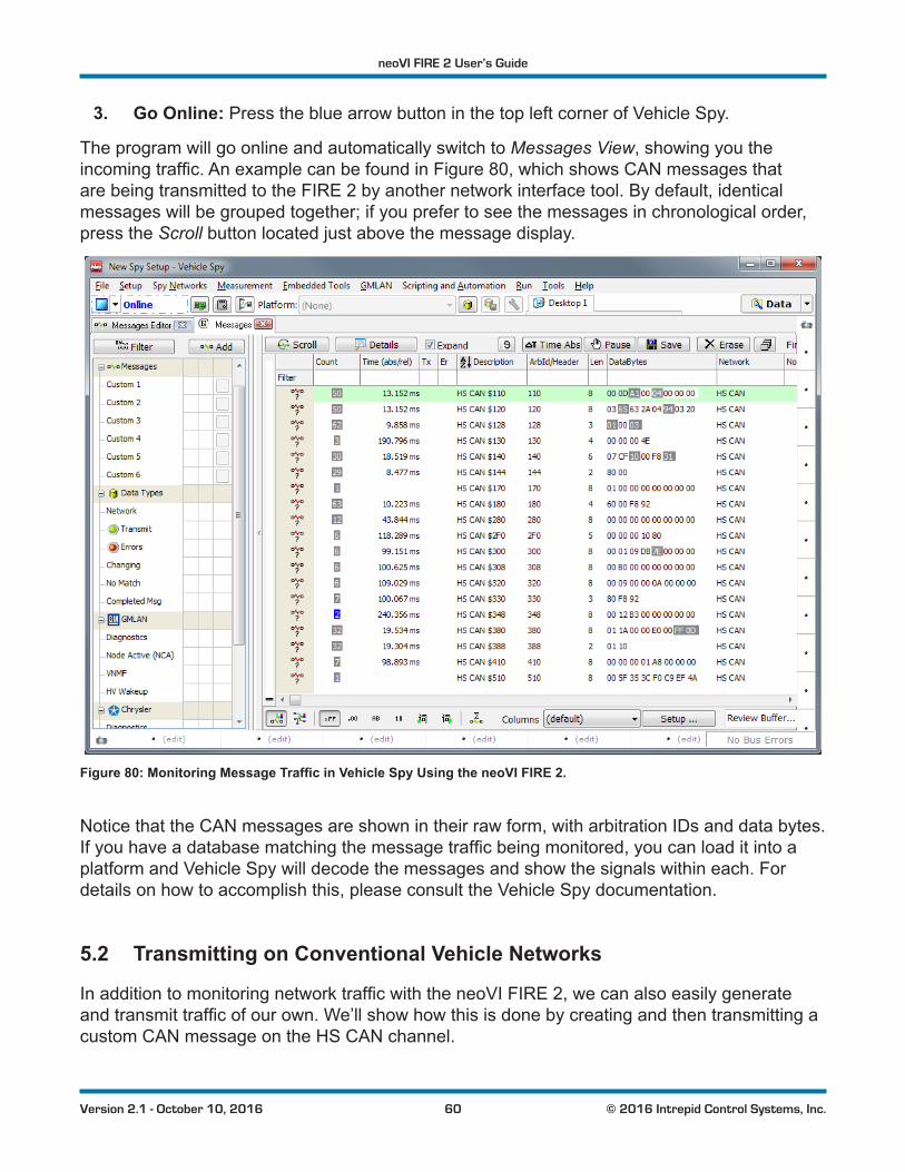
neoVI FIRE 2 User’s Guide
60 © 2016 Intrepid Control Systems, Inc.Version 2.1 - October 10, 2016
3. Go Online: Press the blue arrow button in the top left corner of Vehicle Spy.
The program will go online and automatically switch to Messages View, showing you the incomingtraffic.AnexamplecanbefoundinFigure 80, which shows CAN messages that are being transmitted to the FIRE 2 by another network interface tool. By default, identical messages will be grouped together; if you prefer to see the messages in chronological order, press the Scroll button located just above the message display.
Figure 80: Monitoring Message Traffic in Vehicle Spy Using the neoVI FIRE 2.
Notice that the CAN messages are shown in their raw form, with arbitration IDs and data bytes. Ifyouhaveadatabasematchingthemessagetrafficbeingmonitored,youcanloaditintoaplatform and Vehicle Spy will decode the messages and show the signals within each. For details on how to accomplish this, please consult the Vehicle Spy documentation.
5.2 Transmitting on Conventional Vehicle Networks
InadditiontomonitoringnetworktrafficwiththeneoVIFIRE2,wecanalsoeasilygenerateandtransmittrafficofourown.We’llshowhowthisisdonebycreatingandthentransmittingacustom CAN message on the HS CAN channel.
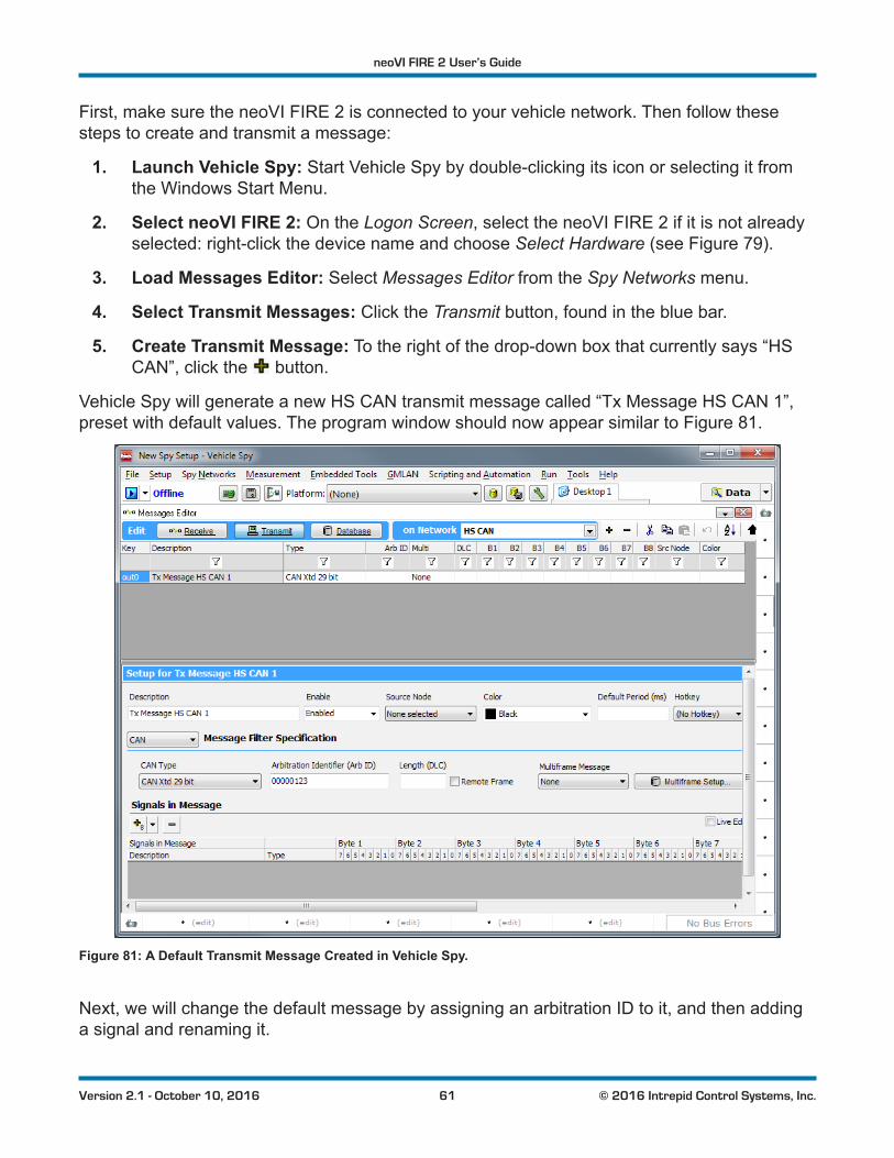
neoVI FIRE 2 User’s Guide
61 © 2016 Intrepid Control Systems, Inc.Version 2.1 - October 10, 2016
First, make sure the neoVI FIRE 2 is connected to your vehicle network. Then follow these steps to create and transmit a message:
1. Launch Vehicle Spy: Start Vehicle Spy by double-clicking its icon or selecting it from the Windows Start Menu.
2. Select neoVI FIRE 2: On the Logon Screen, select the neoVI FIRE 2 if it is not already selected: right-click the device name and choose Select Hardware (see Figure 79).
3. Load Messages Editor: Select Messages Editor from the Spy Networks menu.
4. Select Transmit Messages: Click the Transmit button, found in the blue bar.
5. Create Transmit Message: To the right of the drop-down box that currently says “HS CAN”, click the button.
Vehicle Spy will generate a new HS CAN transmit message called “Tx Message HS CAN 1”, preset with default values. The program window should now appear similar to Figure 81.
Figure 81: A Default Transmit Message Created in Vehicle Spy.
Next, we will change the default message by assigning an arbitration ID to it, and then adding a signal and renaming it.
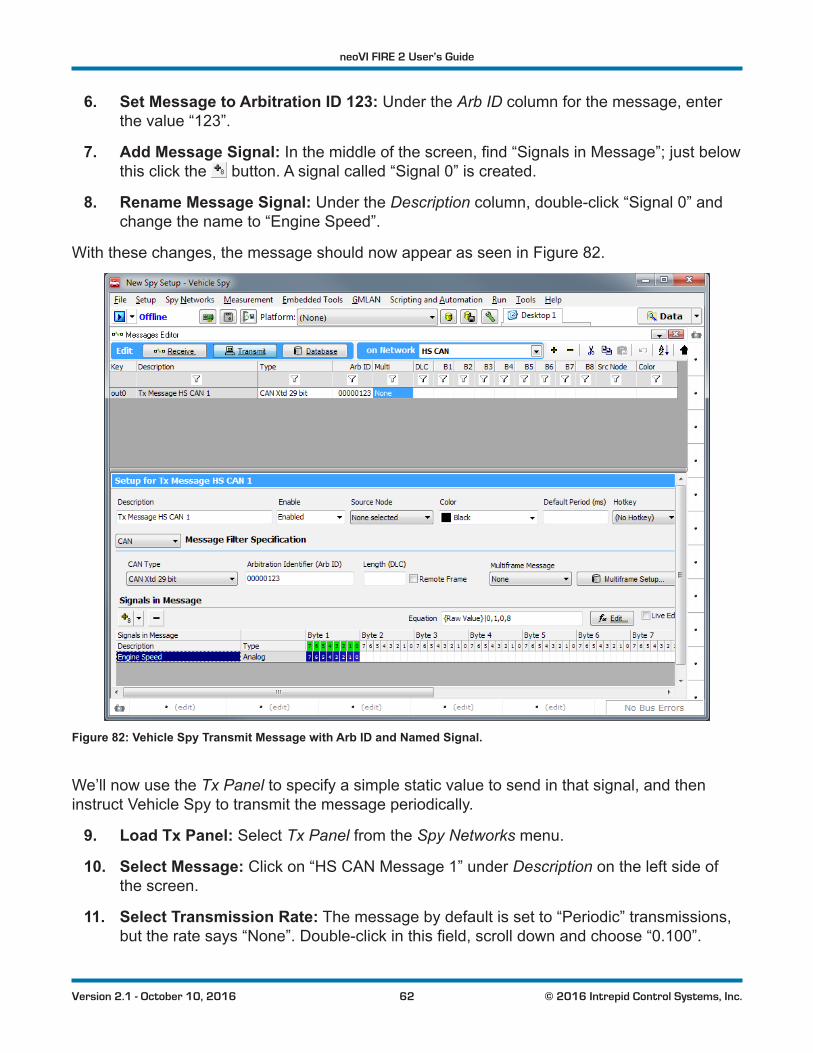
neoVI FIRE 2 User’s Guide
62 © 2016 Intrepid Control Systems, Inc.Version 2.1 - October 10, 2016
6. Set Message to Arbitration ID 123: Under the Arb ID column for the message, enter the value “123”.
7. Add Message Signal:Inthemiddleofthescreen,find“SignalsinMessage”;justbelowthis click the button. A signal called “Signal 0” is created.
8. Rename Message Signal: Under the Description column, double-click “Signal 0” and change the name to “Engine Speed”.
With these changes, the message should now appear as seen in Figure 82.
Figure 82: Vehicle Spy Transmit Message with Arb ID and Named Signal.
We’ll now use the Tx Panel to specify a simple static value to send in that signal, and then instruct Vehicle Spy to transmit the message periodically.
9. Load Tx Panel: Select Tx Panel from the Spy Networks menu.
10. Select Message: Click on “HS CAN Message 1” under Description on the left side of the screen.
11. Select Transmission Rate: The message by default is set to “Periodic” transmissions, buttheratesays“None”.Double-clickinthisfield,scrolldownandchoose“0.100”.
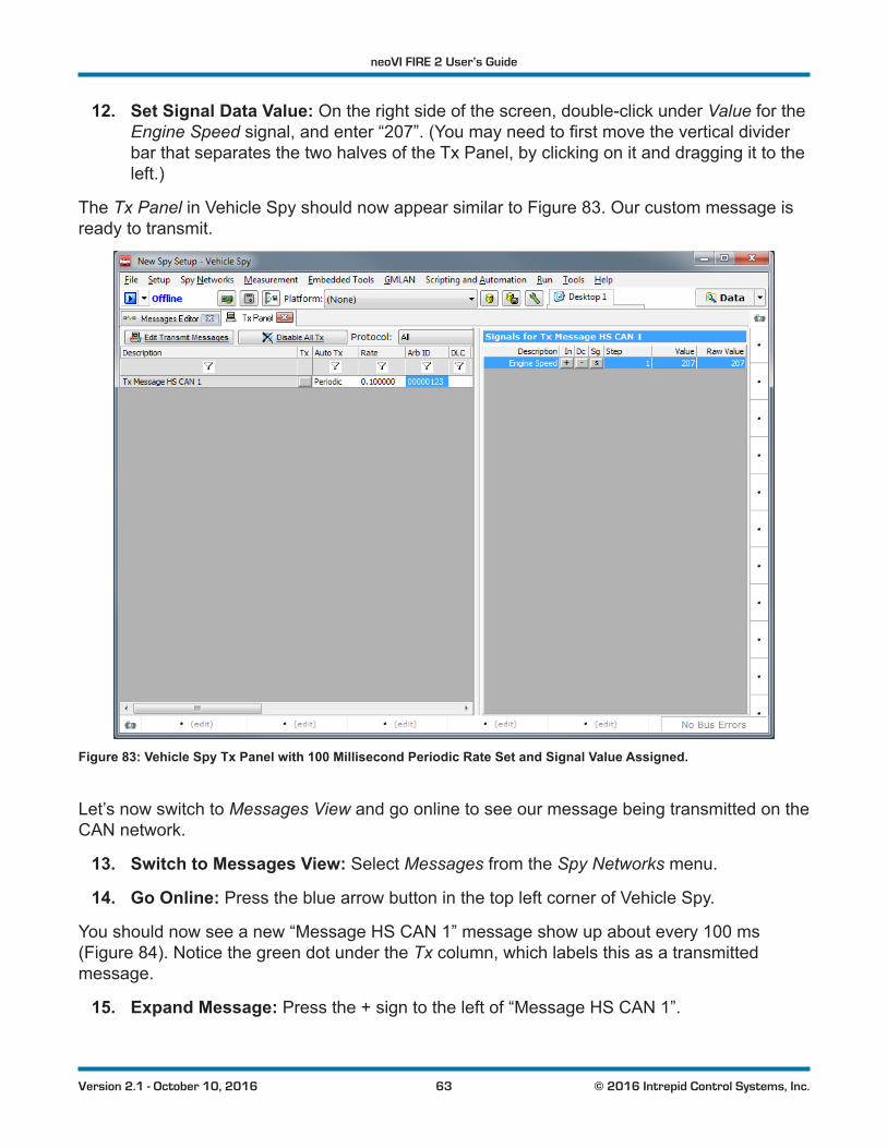
neoVI FIRE 2 User’s Guide
63 © 2016 Intrepid Control Systems, Inc.Version 2.1 - October 10, 2016
12. Set Signal Data Value: On the right side of the screen, double-click under Value for the Engine Speed signal,andenter“207”.(Youmayneedtofirstmovetheverticaldividerbar that separates the two halves of the Tx Panel, by clicking on it and dragging it to the left.)
The Tx Panel in Vehicle Spy should now appear similar to Figure 83. Our custom message is ready to transmit.
Figure 83: Vehicle Spy Tx Panel with 100 Millisecond Periodic Rate Set and Signal Value Assigned.
Let’s now switch to Messages View and go online to see our message being transmitted on the CAN network.
13. Switch to Messages View: Select Messages from the Spy Networks menu.
14. Go Online: Press the blue arrow button in the top left corner of Vehicle Spy.
You should now see a new “Message HS CAN 1” message show up about every 100 ms (Figure 84). Notice the green dot under the Tx column, which labels this as a transmitted message.
15. Expand Message: Press the + sign to the left of “Message HS CAN 1”.
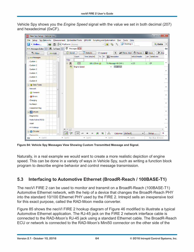
neoVI FIRE 2 User’s Guide
64 © 2016 Intrepid Control Systems, Inc.Version 2.1 - October 10, 2016
Vehicle Spy shows you the Engine Speed signal with the value we set in both decimal (207) and hexadecimal (0xCF).
Figure 84: Vehicle Spy Messages View Showing Custom Transmitted Message and Signal.
Naturally, in a real example we would want to create a more realistic depiction of engine speed. This can be done in a variety of ways in Vehicle Spy, such as writing a function block program to describe engine behavior and control message transmission.
5.3 Interfacing to Automotive Ethernet (BroadR-Reach / 100BASE-T1)
The neoVI FIRE 2 can be used to monitor and transmit on a BroadR-Reach (100BASE-T1) Automotive Ethernet network, with the help of a device that changes the BroadR-Reach PHY into the standard 10/100 Ethernet PHY used by the FIRE 2. Intrepid sells an inexpensive tool for this exact purpose, called the RAD-Moon media converter.
Figure 85 shows the neoVI FIRE 2 hookup diagram of Figure 46modifiedtoillustrateatypicalAutomotive Ethernet application. The RJ-45 jack on the FIRE 2 network interface cable is connected to the RAD-Moon’s RJ-45 jack using a standard Ethernet cable. The BroadR-Reach ECU or network is connected to the RAD-Moon’s Mini50 connector on the other side of the
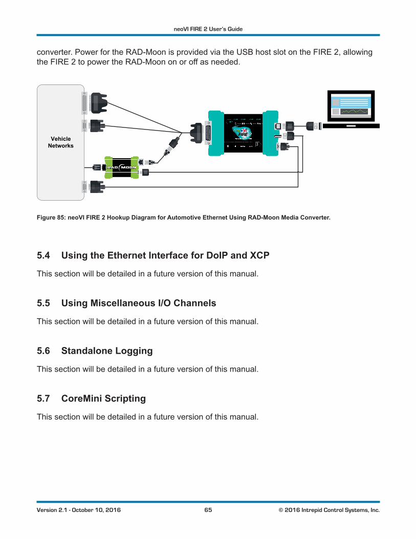
neoVI FIRE 2 User’s Guide
65 © 2016 Intrepid Control Systems, Inc.Version 2.1 - October 10, 2016
converter. Power for the RAD-Moon is provided via the USB host slot on the FIRE 2, allowing the FIRE 2 to power the RAD-Moon on or off as needed.
VehicleNetworks
Figure 85: neoVI FIRE 2 Hookup Diagram for Automotive Ethernet Using RAD-Moon Media Converter.
5.4 Using the Ethernet Interface for DoIP and XCP
This section will be detailed in a future version of this manual.
5.5 Using Miscellaneous I/O Channels
This section will be detailed in a future version of this manual.
5.6 Standalone Logging
This section will be detailed in a future version of this manual.
5.7 CoreMini Scripting
This section will be detailed in a future version of this manual.
neoVI FIRE 2 User’s Guide
66 © 2016 Intrepid Control Systems, Inc.Version 2.1 - October 10, 2016
6 Advanced FeaturesIn this chapter we provide additional information on some of the neoVI FIRE 2’s new and advanced features.
Note that some of these features are not yet currently implemented in the neoVI FIRE 2, but theircapabilitieswillbeprovidedinfuturefirmwareupgrades,atwhichtimethismanualwillbeupdated to explain their use.
6.1 neoVI API
The neoVI FIRE 2 comes with support for a full API that allows you to control the device from other software packages or custom-written software. For instructions on using the API, please consult its documentation on the Intrepid website at: http://www.intrepidcs.com/support/ICSDocumentation/neoVIDLL/neoVIDLLhelpdoc.html.
6.2 USB Host
The neoVI FIRE 2 comes with a USB host port that allows other devices to be plugged into it (see Figure 6 in Section 2.3).Duetothedifficultiesassociatedwithdriverdevelopment,thisportisintendedforspecificdevicesratherthangeneralpurposeuse.Itisespeciallydesignedto work with devices such as the Intrepid neoVI MIC microphone/trigger pendant, or the RAD-Moon (as seen in Section 5.3).
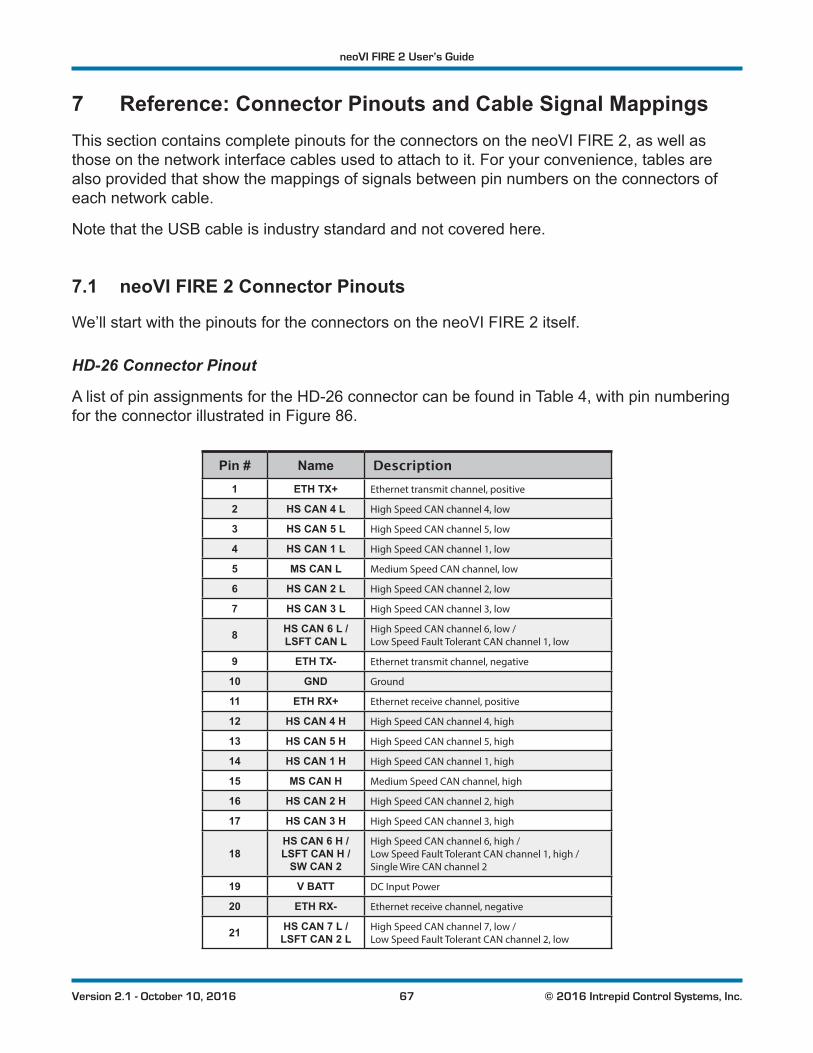
neoVI FIRE 2 User’s Guide
67 © 2016 Intrepid Control Systems, Inc.Version 2.1 - October 10, 2016
7 Reference: Connector Pinouts and Cable Signal MappingsThis section contains complete pinouts for the connectors on the neoVI FIRE 2, as well as those on the network interface cables used to attach to it. For your convenience, tables are also provided that show the mappings of signals between pin numbers on the connectors of each network cable.
Note that the USB cable is industry standard and not covered here.
7.1 neoVI FIRE 2 Connector Pinouts
We’ll start with the pinouts for the connectors on the neoVI FIRE 2 itself.
HD-26 Connector Pinout
A list of pin assignments for the HD-26 connector can be found in Table 4, with pin numbering for the connector illustrated in Figure 86.
Pin # Name Description1 ETH TX+ Ethernet transmit channel, positive
2 HS CAN 4 L High Speed CAN channel 4, low
3 HS CAN 5 L High Speed CAN channel 5, low
4 HS CAN 1 L High Speed CAN channel 1, low
5 MS CAN L Medium Speed CAN channel, low
6 HS CAN 2 L High Speed CAN channel 2, low
7 HS CAN 3 L High Speed CAN channel 3, low
8 HS CAN 6 L / LSFT CAN L
High Speed CAN channel 6, low / Low Speed Fault Tolerant CAN channel 1, low
9 ETH TX- Ethernet transmit channel, negative
10 GND Ground
11 ETH RX+ Ethernet receive channel, positive
12 HS CAN 4 H High Speed CAN channel 4, high
13 HS CAN 5 H High Speed CAN channel 5, high
14 HS CAN 1 H High Speed CAN channel 1, high
15 MS CAN H Medium Speed CAN channel, high
16 HS CAN 2 H High Speed CAN channel 2, high
17 HS CAN 3 H High Speed CAN channel 3, high
18HS CAN 6 H / LSFT CAN H /
SW CAN 2
High Speed CAN channel 6, high / Low Speed Fault Tolerant CAN channel 1, high / Single Wire CAN channel 2
19 V BATT DC Input Power
20 ETH RX- Ethernet receive channel, negative
21 HS CAN 7 L / LSFT CAN 2 L
High Speed CAN channel 7, low / Low Speed Fault Tolerant CAN channel 2, low
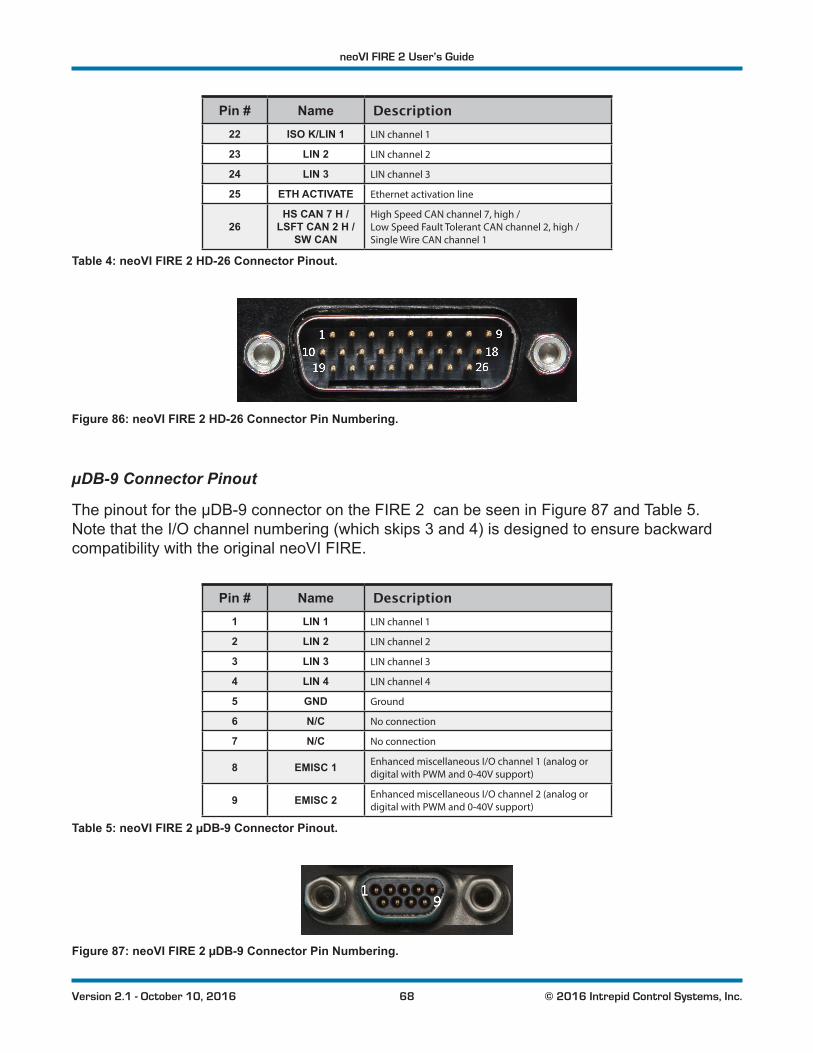
neoVI FIRE 2 User’s Guide
68 © 2016 Intrepid Control Systems, Inc.Version 2.1 - October 10, 2016
Pin # Name Description22 ISO K/LIN 1 LIN channel 1
23 LIN 2 LIN channel 2
24 LIN 3 LIN channel 3
25 ETH ACTIVATE Ethernet activation line
26HS CAN 7 H /
LSFT CAN 2 H / SW CAN
High Speed CAN channel 7, high / Low Speed Fault Tolerant CAN channel 2, high / Single Wire CAN channel 1
Table 4: neoVI FIRE 2 HD-26 Connector Pinout.
Figure 86: neoVI FIRE 2 HD-26 Connector Pin Numbering.
µDB-9 Connector Pinout
The pinout for the µDB-9 connector on the FIRE 2 can be seen in Figure 87 and Table 5. Note that the I/O channel numbering (which skips 3 and 4) is designed to ensure backward compatibility with the original neoVI FIRE.
Pin # Name Description1 LIN 1 LIN channel 1
2 LIN 2 LIN channel 2
3 LIN 3 LIN channel 3
4 LIN 4 LIN channel 4
5 GND Ground
6 N/C No connection
7 N/C No connection
8 EMISC 1 Enhanced miscellaneous I/O channel 1 (analog or digital with PWM and 0-40V support)
9 EMISC 2 Enhanced miscellaneous I/O channel 2 (analog or digital with PWM and 0-40V support)
Table 5: neoVI FIRE 2 µDB-9 Connector Pinout.
Figure 87: neoVI FIRE 2 µDB-9 Connector Pin Numbering.
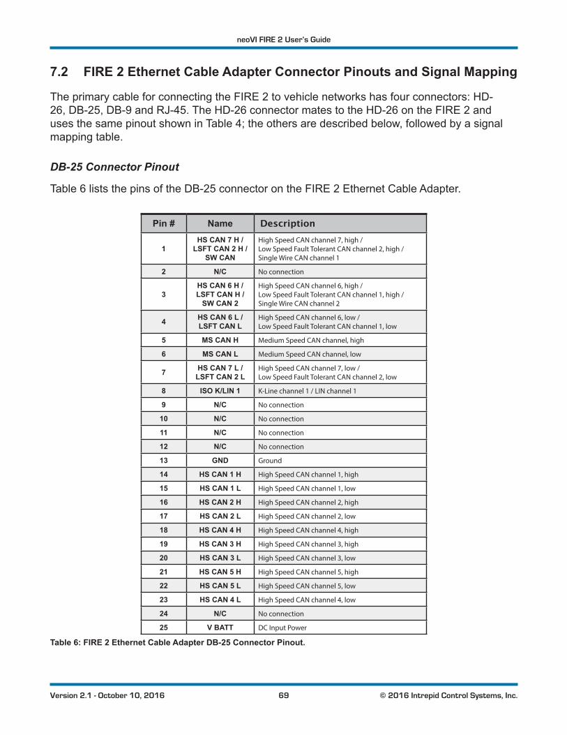
neoVI FIRE 2 User’s Guide
69 © 2016 Intrepid Control Systems, Inc.Version 2.1 - October 10, 2016
7.2 FIRE 2 Ethernet Cable Adapter Connector Pinouts and Signal Mapping
The primary cable for connecting the FIRE 2 to vehicle networks has four connectors: HD-26, DB-25, DB-9 and RJ-45. The HD-26 connector mates to the HD-26 on the FIRE 2 and uses the same pinout shown in Table 4; the others are described below, followed by a signal mapping table.
DB-25 Connector Pinout
Table 6 lists the pins of the DB-25 connector on the FIRE 2 Ethernet Cable Adapter.
Pin # Name Description
1HS CAN 7 H /
LSFT CAN 2 H / SW CAN
High Speed CAN channel 7, high / Low Speed Fault Tolerant CAN channel 2, high / Single Wire CAN channel 1
2 N/C No connection
3HS CAN 6 H / LSFT CAN H /
SW CAN 2
High Speed CAN channel 6, high / Low Speed Fault Tolerant CAN channel 1, high / Single Wire CAN channel 2
4 HS CAN 6 L / LSFT CAN L
High Speed CAN channel 6, low / Low Speed Fault Tolerant CAN channel 1, low
5 MS CAN H Medium Speed CAN channel, high
6 MS CAN L Medium Speed CAN channel, low
7 HS CAN 7 L / LSFT CAN 2 L
High Speed CAN channel 7, low / Low Speed Fault Tolerant CAN channel 2, low
8 ISO K/LIN 1 K-Line channel 1 / LIN channel 1
9 N/C No connection
10 N/C No connection
11 N/C No connection
12 N/C No connection
13 GND Ground
14 HS CAN 1 H High Speed CAN channel 1, high
15 HS CAN 1 L High Speed CAN channel 1, low
16 HS CAN 2 H High Speed CAN channel 2, high
17 HS CAN 2 L High Speed CAN channel 2, low
18 HS CAN 4 H High Speed CAN channel 4, high
19 HS CAN 3 H High Speed CAN channel 3, high
20 HS CAN 3 L High Speed CAN channel 3, low
21 HS CAN 5 H High Speed CAN channel 5, high
22 HS CAN 5 L High Speed CAN channel 5, low
23 HS CAN 4 L High Speed CAN channel 4, low
24 N/C No connection
25 V BATT DC Input Power
Table 6: FIRE 2 Ethernet Cable Adapter DB-25 Connector Pinout.
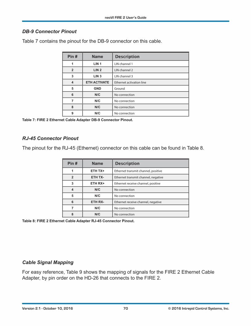
neoVI FIRE 2 User’s Guide
70 © 2016 Intrepid Control Systems, Inc.Version 2.1 - October 10, 2016
DB-9 Connector Pinout
Table 7 contains the pinout for the DB-9 connector on this cable.
Pin # Name Description1 LIN 1 LIN channel 1
2 LIN 2 LIN channel 2
3 LIN 3 LIN channel 3
4 ETH ACTIVATE Ethernet activation line
5 GND Ground
6 N/C No connection
7 N/C No connection
8 N/C No connection
9 N/C No connection
Table 7: FIRE 2 Ethernet Cable Adapter DB-9 Connector Pinout.
RJ-45 Connector Pinout
The pinout for the RJ-45 (Ethernet) connector on this cable can be found in Table 8.
Pin # Name Description1 ETH TX+ Ethernet transmit channel, positive
2 ETH TX- Ethernet transmit channel, negative
3 ETH RX+ Ethernet receive channel, positive
4 N/C No connection
5 N/C No connection
6 ETH RX- Ethernet receive channel, negative
7 N/C No connection
8 N/C No connection
Table 8: FIRE 2 Ethernet Cable Adapter RJ-45 Connector Pinout.
Cable Signal Mapping
For easy reference, Table 9 shows the mapping of signals for the FIRE 2 Ethernet Cable Adapter, by pin order on the HD-26 that connects to the FIRE 2.
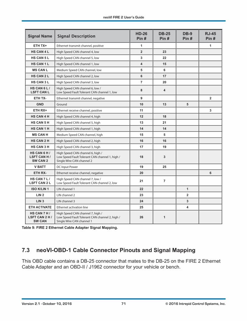
neoVI FIRE 2 User’s Guide
71 © 2016 Intrepid Control Systems, Inc.Version 2.1 - October 10, 2016
Signal Name Signal Description HD-26 Pin #
DB-25 Pin #
DB-9 Pin #
RJ-45 Pin #
ETH TX+ Ethernet transmit channel, positive 1 1
HS CAN 4 L High Speed CAN channel 4, low 2 23
HS CAN 5 L High Speed CAN channel 5, low 3 22
HS CAN 1 L High Speed CAN channel 1, low 4 15
MS CAN L Medium Speed CAN channel, low 5 6
HS CAN 2 L High Speed CAN channel 2, low 6 17
HS CAN 3 L High Speed CAN channel 3, low 7 20
HS CAN 6 L / LSFT CAN L
High Speed CAN channel 6, low / Low Speed Fault Tolerant CAN channel 1, low
8 4
ETH TX- Ethernet transmit channel, negative 9 2
GND Ground 10 13 5
ETH RX+ Ethernet receive channel, positive 11 3
HS CAN 4 H High Speed CAN channel 4, high 12 18
HS CAN 5 H High Speed CAN channel 5, high 13 21
HS CAN 1 H High Speed CAN channel 1, high 14 14
MS CAN H Medium Speed CAN channel, high 15 5
HS CAN 2 H High Speed CAN channel 2, high 16 16
HS CAN 3 H High Speed CAN channel 3, high 17 19
HS CAN 6 H / LSFT CAN H /
SW CAN 2
High Speed CAN channel 6, high / Low Speed Fault Tolerant CAN channel 1, high / Single Wire CAN channel 2
18 3
V BATT DC Input Power 19 25
ETH RX- Ethernet receive channel, negative 20 6
HS CAN 7 L / LSFT CAN 2 L
High Speed CAN channel 7, low / Low Speed Fault Tolerant CAN channel 2, low
21 7
ISO K/LIN 1 LIN channel 1 22 1
LIN 2 LIN channel 2 23 2
LIN 3 LIN channel 3 24 3
ETH ACTIVATE Ethernet activation line 25 4
HS CAN 7 H / LSFT CAN 2 H /
SW CAN
High Speed CAN channel 7, high / Low Speed Fault Tolerant CAN channel 2, high / Single Wire CAN channel 1
26 1
Table 9: FIRE 2 Ethernet Cable Adapter Signal Mapping.
7.3 neoVI-OBD-1 Cable Connector Pinouts and Signal Mapping
This OBD cable contains a DB-25 connector that mates to the DB-25 on the FIRE 2 Ethernet Cable Adapter and an OBD-II / J1962 connector for your vehicle or bench.
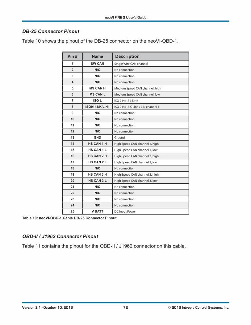
neoVI FIRE 2 User’s Guide
72 © 2016 Intrepid Control Systems, Inc.Version 2.1 - October 10, 2016
DB-25 Connector Pinout
Table 10 shows the pinout of the DB-25 connector on the neoVI-OBD-1.
Pin # Name Description1 SW CAN Single Wire CAN channel
2 N/C No connection
3 N/C No connection
4 N/C No connection
5 MS CAN H Medium Speed CAN channel, high
6 MS CAN L Medium Speed CAN channel, low
7 ISO L ISO 9141-2 L-Line
8 ISO9141/K/LIN1 ISO 9141-2 K-Line / LIN channel 1
9 N/C No connection
10 N/C No connection
11 N/C No connection
12 N/C No connection
13 GND Ground
14 HS CAN 1 H High Speed CAN channel 1, high
15 HS CAN 1 L High Speed CAN channel 1, low
16 HS CAN 2 H High Speed CAN channel 2, high
17 HS CAN 2 L High Speed CAN channel 2, low
18 N/C No connection
19 HS CAN 3 H High Speed CAN channel 3, high
20 HS CAN 3 L High Speed CAN channel 3, low
21 N/C No connection
22 N/C No connection
23 N/C No connection
24 N/C No connection
25 V BATT DC Input Power
Table 10: neoVI-OBD-1 Cable DB-25 Connector Pinout.
OBD-II / J1962 Connector Pinout
Table 11 contains the pinout for the OBD-II / J1962 connector on this cable.
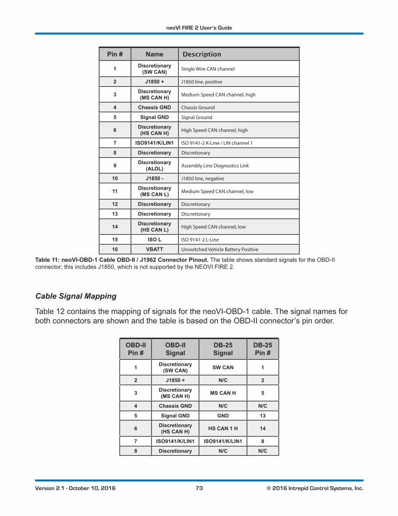
neoVI FIRE 2 User’s Guide
73 © 2016 Intrepid Control Systems, Inc.Version 2.1 - October 10, 2016
Pin # Name Description
1 Discretionary (SW CAN) Single Wire CAN channel
2 J1850 + J1850 line, positive
3 Discretionary (MS CAN H) Medium Speed CAN channel, high
4 Chassis GND Chassis Ground
5 Signal GND Signal Ground
6 Discretionary (HS CAN H) High Speed CAN channel, high
7 ISO9141/K/LIN1 ISO 9141-2 K-Line / LIN channel 1
8 Discretionary Discretionary
9 Discretionary (ALDL) Assembly Line Diagnostics Link
10 J1850 - J1850 line, negative
11 Discretionary (MS CAN L) Medium Speed CAN channel, low
12 Discretionary Discretionary
13 Discretionary Discretionary
14 Discretionary (HS CAN L) High Speed CAN channel, low
15 ISO L ISO 9141-2 L-Line
16 VBATT Unswitched Vehicle Battery Positive
Table 11: neoVI-OBD-1 Cable OBD-II / J1962 Connector Pinout. The table shows standard signals for the OBD-II connector; this includes J1850, which is not supported by the NEOVI FIRE 2.
Cable Signal Mapping
Table 12 contains the mapping of signals for the neoVI-OBD-1 cable. The signal names for both connectors are shown and the table is based on the OBD-II connector’s pin order.
OBD-II Pin #
OBD-II Signal
DB-25 Signal
DB-25 Pin #
1 Discretionary (SW CAN) SW CAN 1
2 J1850 + N/C 2
3 Discretionary (MS CAN H) MS CAN H 5
4 Chassis GND N/C N/C
5 Signal GND GND 13
6 Discretionary (HS CAN H) HS CAN 1 H 14
7 ISO9141/K/LIN1 ISO9141/K/LIN1 8
8 Discretionary N/C N/C
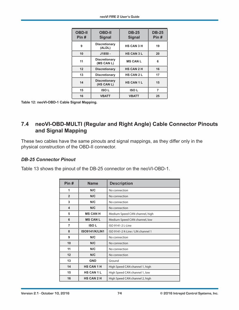
neoVI FIRE 2 User’s Guide
74 © 2016 Intrepid Control Systems, Inc.Version 2.1 - October 10, 2016
OBD-II Pin #
OBD-II Signal
DB-25 Signal
DB-25 Pin #
9 Discretionary (ALDL) HS CAN 3 H 19
10 J1850 - HS CAN 3 L 20
11 Discretionary (MS CAN L) MS CAN L 6
12 Discretionary HS CAN 2 H 16
13 Discretionary HS CAN 2 L 17
14 Discretionary (HS CAN L) HS CAN 1 L 15
15 ISO L ISO L 7
16 VBATT VBATT 25
Table 12: neoVI-OBD-1 Cable Signal Mapping.
7.4 neoVI-OBD-MULTI (Regular and Right Angle) Cable Connector Pinouts and Signal Mapping
These two cables have the same pinouts and signal mappings, as they differ only in the physical construction of the OBD-II connector.
DB-25 Connector Pinout
Table 13 shows the pinout of the DB-25 connector on the neoVI-OBD-1.
Pin # Name Description1 N/C No connection
2 N/C No connection
3 N/C No connection
4 N/C No connection
5 MS CAN H Medium Speed CAN channel, high
6 MS CAN L Medium Speed CAN channel, low
7 ISO L ISO 9141-2 L-Line
8 ISO9141/K/LIN1 ISO 9141-2 K-Line / LIN channel 1
9 N/C No connection
10 N/C No connection
11 N/C No connection
12 N/C No connection
13 GND Ground
14 HS CAN 1 H High Speed CAN channel 1, high
15 HS CAN 1 L High Speed CAN channel 1, low
16 HS CAN 2 H High Speed CAN channel 2, high
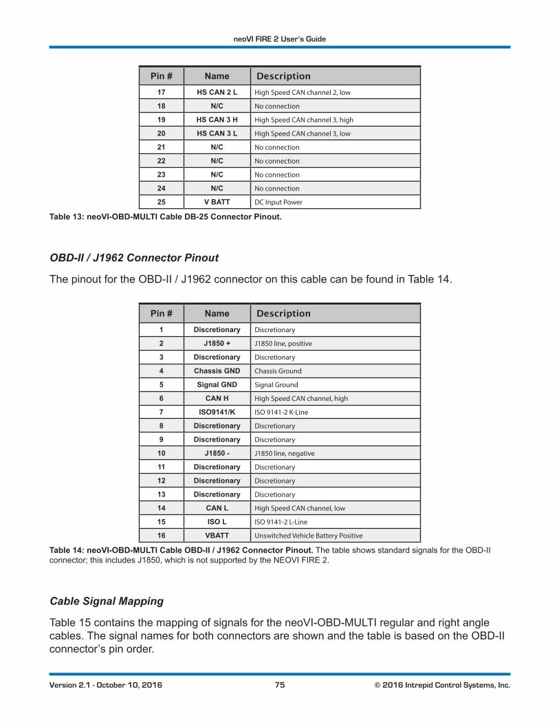
neoVI FIRE 2 User’s Guide
75 © 2016 Intrepid Control Systems, Inc.Version 2.1 - October 10, 2016
Pin # Name Description17 HS CAN 2 L High Speed CAN channel 2, low
18 N/C No connection
19 HS CAN 3 H High Speed CAN channel 3, high
20 HS CAN 3 L High Speed CAN channel 3, low
21 N/C No connection
22 N/C No connection
23 N/C No connection
24 N/C No connection
25 V BATT DC Input Power
Table 13: neoVI-OBD-MULTI Cable DB-25 Connector Pinout.
OBD-II / J1962 Connector Pinout
The pinout for the OBD-II / J1962 connector on this cable can be found in Table 14.
Pin # Name Description1 Discretionary Discretionary
2 J1850 + J1850 line, positive
3 Discretionary Discretionary
4 Chassis GND Chassis Ground
5 Signal GND Signal Ground
6 CAN H High Speed CAN channel, high
7 ISO9141/K ISO 9141-2 K-Line
8 Discretionary Discretionary
9 Discretionary Discretionary
10 J1850 - J1850 line, negative
11 Discretionary Discretionary
12 Discretionary Discretionary
13 Discretionary Discretionary
14 CAN L High Speed CAN channel, low
15 ISO L ISO 9141-2 L-Line
16 VBATT Unswitched Vehicle Battery Positive
Table 14: neoVI-OBD-MULTI Cable OBD-II / J1962 Connector Pinout. The table shows standard signals for the OBD-II connector; this includes J1850, which is not supported by the NEOVI FIRE 2.
Cable Signal Mapping
Table 15 contains the mapping of signals for the neoVI-OBD-MULTI regular and right angle cables. The signal names for both connectors are shown and the table is based on the OBD-II connector’s pin order.
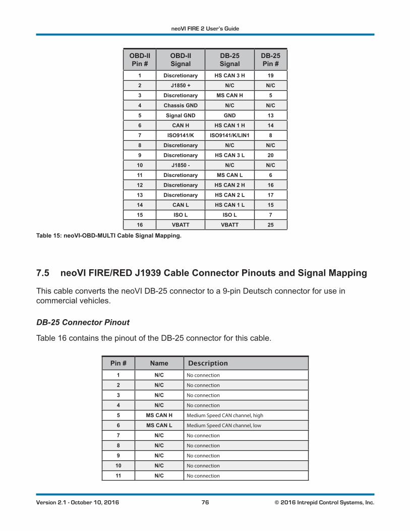
neoVI FIRE 2 User’s Guide
76 © 2016 Intrepid Control Systems, Inc.Version 2.1 - October 10, 2016
OBD-II Pin #
OBD-II Signal
DB-25 Signal
DB-25 Pin #
1 Discretionary HS CAN 3 H 19
2 J1850 + N/C N/C
3 Discretionary MS CAN H 5
4 Chassis GND N/C N/C
5 Signal GND GND 13
6 CAN H HS CAN 1 H 14
7 ISO9141/K ISO9141/K/LIN1 8
8 Discretionary N/C N/C
9 Discretionary HS CAN 3 L 20
10 J1850 - N/C N/C
11 Discretionary MS CAN L 6
12 Discretionary HS CAN 2 H 16
13 Discretionary HS CAN 2 L 17
14 CAN L HS CAN 1 L 15
15 ISO L ISO L 7
16 VBATT VBATT 25
Table 15: neoVI-OBD-MULTI Cable Signal Mapping.
7.5 neoVI FIRE/RED J1939 Cable Connector Pinouts and Signal Mapping
This cable converts the neoVI DB-25 connector to a 9-pin Deutsch connector for use in commercial vehicles.
DB-25 Connector Pinout
Table 16 contains the pinout of the DB-25 connector for this cable.
Pin # Name Description1 N/C No connection
2 N/C No connection
3 N/C No connection
4 N/C No connection
5 MS CAN H Medium Speed CAN channel, high
6 MS CAN L Medium Speed CAN channel, low
7 N/C No connection
8 N/C No connection
9 N/C No connection
10 N/C No connection
11 N/C No connection
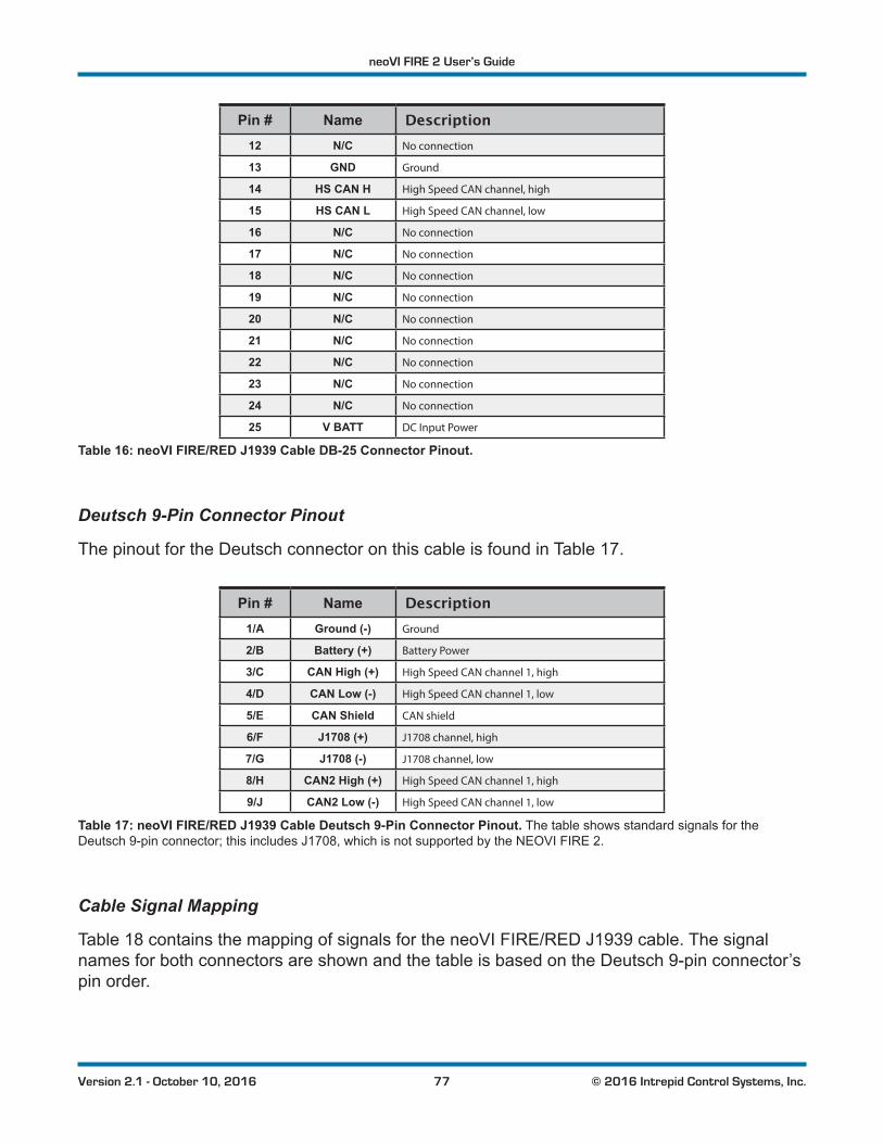
neoVI FIRE 2 User’s Guide
77 © 2016 Intrepid Control Systems, Inc.Version 2.1 - October 10, 2016
Pin # Name Description12 N/C No connection
13 GND Ground
14 HS CAN H High Speed CAN channel, high
15 HS CAN L High Speed CAN channel, low
16 N/C No connection
17 N/C No connection
18 N/C No connection
19 N/C No connection
20 N/C No connection
21 N/C No connection
22 N/C No connection
23 N/C No connection
24 N/C No connection
25 V BATT DC Input Power
Table 16: neoVI FIRE/RED J1939 Cable DB-25 Connector Pinout.
Deutsch 9-Pin Connector Pinout
The pinout for the Deutsch connector on this cable is found in Table 17.
Pin # Name Description1/A Ground (-) Ground
2/B Battery (+) Battery Power
3/C CAN High (+) High Speed CAN channel 1, high
4/D CAN Low (-) High Speed CAN channel 1, low
5/E CAN Shield CAN shield
6/F J1708 (+) J1708 channel, high
7/G J1708 (-) J1708 channel, low
8/H CAN2 High (+) High Speed CAN channel 1, high
9/J CAN2 Low (-) High Speed CAN channel 1, low
Table 17: neoVI FIRE/RED J1939 Cable Deutsch 9-Pin Connector Pinout. The table shows standard signals for the Deutsch 9-pin connector; this includes J1708, which is not supported by the NEOVI FIRE 2.
Cable Signal Mapping
Table 18 contains the mapping of signals for the neoVI FIRE/RED J1939 cable. The signal names for both connectors are shown and the table is based on the Deutsch 9-pin connector’s pin order.
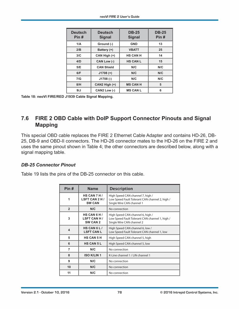
neoVI FIRE 2 User’s Guide
78 © 2016 Intrepid Control Systems, Inc.Version 2.1 - October 10, 2016
Deutsch Pin #
Deutsch Signal
DB-25 Signal
DB-25 Pin #
1/A Ground (-) GND 13
2/B Battery (+) VBATT 25
3/C CAN High (+) HS CAN H 14
4/D CAN Low (-) HS CAN L 15
5/E CAN Shield N/C N/C
6/F J1708 (+) N/C N/C
7/G J1708 (-) N/C N/C
8/H CAN2 High (+) MS CAN H 5
9/J CAN2 Low (-) MS CAN L 6
Table 18: neoVI FIRE/RED J1939 Cable Signal Mapping.
7.6 FIRE 2 OBD Cable with DoIP Support Connector Pinouts and Signal Mapping
This special OBD cable replaces the FIRE 2 Ethernet Cable Adapter and contains HD-26, DB-25, DB-9 and OBD-II connectors. The HD-26 connector mates to the HD-26 on the FIRE 2 and uses the same pinout shown in Table 4; the other connectors are described below, along with a signal mapping table.
DB-25 Connector Pinout
Table 19 lists the pins of the DB-25 connector on this cable.
Pin # Name Description
1HS CAN 7 H /
LSFT CAN 2 H / SW CAN
High Speed CAN channel 7, high / Low Speed Fault Tolerant CAN channel 2, high / Single Wire CAN channel 1
2 N/C No connection
3HS CAN 6 H / LSFT CAN H /
SW CAN 2
High Speed CAN channel 6, high / Low Speed Fault Tolerant CAN channel 1, high / Single Wire CAN channel 2
4 HS CAN 6 L / LSFT CAN L
High Speed CAN channel 6, low / Low Speed Fault Tolerant CAN channel 1, low
5 HS CAN 5 H High Speed CAN channel 5, high
6 HS CAN 5 L High Speed CAN channel 5, low
7 N/C No connection
8 ISO K/LIN 1 K-Line channel 1 / LIN channel 1
9 N/C No connection
10 N/C No connection
11 N/C No connection
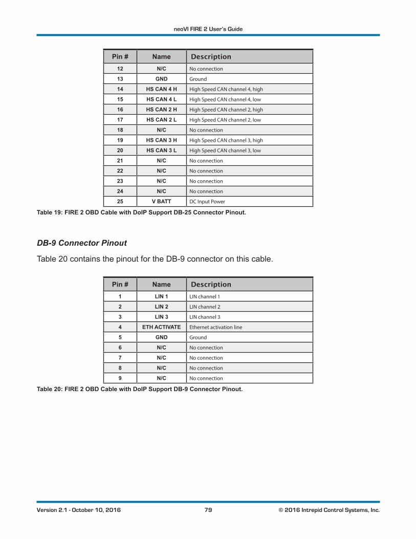
neoVI FIRE 2 User’s Guide
79 © 2016 Intrepid Control Systems, Inc.Version 2.1 - October 10, 2016
Pin # Name Description12 N/C No connection
13 GND Ground
14 HS CAN 4 H High Speed CAN channel 4, high
15 HS CAN 4 L High Speed CAN channel 4, low
16 HS CAN 2 H High Speed CAN channel 2, high
17 HS CAN 2 L High Speed CAN channel 2, low
18 N/C No connection
19 HS CAN 3 H High Speed CAN channel 3, high
20 HS CAN 3 L High Speed CAN channel 3, low
21 N/C No connection
22 N/C No connection
23 N/C No connection
24 N/C No connection
25 V BATT DC Input Power
Table 19: FIRE 2 OBD Cable with DoIP Support DB-25 Connector Pinout.
DB-9 Connector Pinout
Table 20 contains the pinout for the DB-9 connector on this cable.
Pin # Name Description1 LIN 1 LIN channel 1
2 LIN 2 LIN channel 2
3 LIN 3 LIN channel 3
4 ETH ACTIVATE Ethernet activation line
5 GND Ground
6 N/C No connection
7 N/C No connection
8 N/C No connection
9 N/C No connection
Table 20: FIRE 2 OBD Cable with DoIP Support DB-9 Connector Pinout.
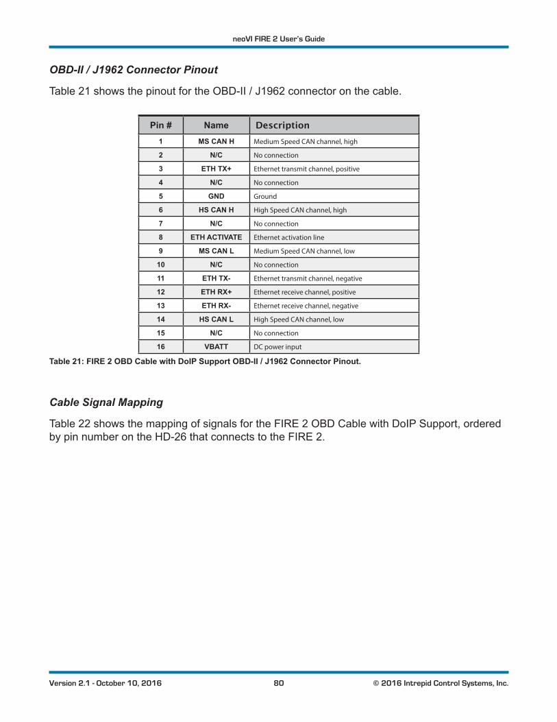
neoVI FIRE 2 User’s Guide
80 © 2016 Intrepid Control Systems, Inc.Version 2.1 - October 10, 2016
OBD-II / J1962 Connector Pinout
Table 21 shows the pinout for the OBD-II / J1962 connector on the cable.
Pin # Name Description1 MS CAN H Medium Speed CAN channel, high
2 N/C No connection
3 ETH TX+ Ethernet transmit channel, positive
4 N/C No connection
5 GND Ground
6 HS CAN H High Speed CAN channel, high
7 N/C No connection
8 ETH ACTIVATE Ethernet activation line
9 MS CAN L Medium Speed CAN channel, low
10 N/C No connection
11 ETH TX- Ethernet transmit channel, negative
12 ETH RX+ Ethernet receive channel, positive
13 ETH RX- Ethernet receive channel, negative
14 HS CAN L High Speed CAN channel, low
15 N/C No connection
16 VBATT DC power input
Table 21: FIRE 2 OBD Cable with DoIP Support OBD-II / J1962 Connector Pinout.
Cable Signal Mapping
Table 22 shows the mapping of signals for the FIRE 2 OBD Cable with DoIP Support, ordered by pin number on the HD-26 that connects to the FIRE 2.
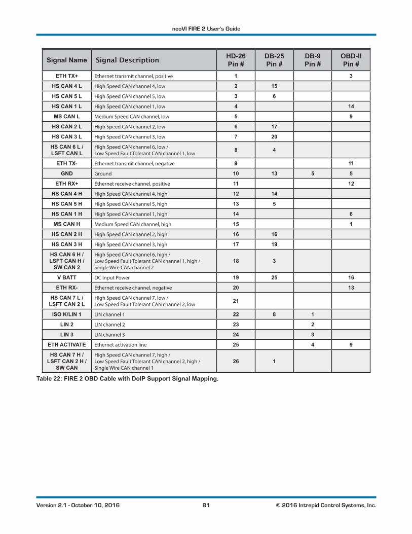
neoVI FIRE 2 User’s Guide
81 © 2016 Intrepid Control Systems, Inc.Version 2.1 - October 10, 2016
Signal Name Signal Description HD-26 Pin #
DB-25 Pin #
DB-9 Pin #
OBD-II Pin #
ETH TX+ Ethernet transmit channel, positive 1 3
HS CAN 4 L High Speed CAN channel 4, low 2 15
HS CAN 5 L High Speed CAN channel 5, low 3 6
HS CAN 1 L High Speed CAN channel 1, low 4 14
MS CAN L Medium Speed CAN channel, low 5 9
HS CAN 2 L High Speed CAN channel 2, low 6 17
HS CAN 3 L High Speed CAN channel 3, low 7 20
HS CAN 6 L / LSFT CAN L
High Speed CAN channel 6, low / Low Speed Fault Tolerant CAN channel 1, low
8 4
ETH TX- Ethernet transmit channel, negative 9 11
GND Ground 10 13 5 5
ETH RX+ Ethernet receive channel, positive 11 12
HS CAN 4 H High Speed CAN channel 4, high 12 14
HS CAN 5 H High Speed CAN channel 5, high 13 5
HS CAN 1 H High Speed CAN channel 1, high 14 6
MS CAN H Medium Speed CAN channel, high 15 1
HS CAN 2 H High Speed CAN channel 2, high 16 16
HS CAN 3 H High Speed CAN channel 3, high 17 19
HS CAN 6 H / LSFT CAN H /
SW CAN 2
High Speed CAN channel 6, high / Low Speed Fault Tolerant CAN channel 1, high / Single Wire CAN channel 2
18 3
V BATT DC Input Power 19 25 16
ETH RX- Ethernet receive channel, negative 20 13
HS CAN 7 L / LSFT CAN 2 L
High Speed CAN channel 7, low / Low Speed Fault Tolerant CAN channel 2, low
21
ISO K/LIN 1 LIN channel 1 22 8 1
LIN 2 LIN channel 2 23 2
LIN 3 LIN channel 3 24 3
ETH ACTIVATE Ethernet activation line 25 4 9
HS CAN 7 H / LSFT CAN 2 H /
SW CAN
High Speed CAN channel 7, high / Low Speed Fault Tolerant CAN channel 2, high / Single Wire CAN channel 1
26 1
Table 22: FIRE 2 OBD Cable with DoIP Support Signal Mapping.

neoVI FIRE 2 User’s Guide
82 © 2016 Intrepid Control Systems, Inc.Version 2.1 - October 10, 2016
8 Support Contact InformationIf you have a problem you cannot resolve on your own, feel free to contact ICS for assistance atoneofouroffices.
8.1 ICS United States Headquarters
Our primary support personnel can be reached at our American headquarters in the Detroit area, using the following contact information:
• Phone: (800) 859-6265 or (586) 731-7950, extension 1.
• Fax: (586) 731-2274.
• Email: [email protected]
Intrepid’s normal support hours are from 8 am to 5 pm, Monday to Friday, United States Eastern time. If you require assistance outside standard business hours, feel free to contact us and a member of our support team will get back to you as soon as possible.
8.2 ICS International Offices
European Union Office
ForsupportintheEU,pleasecontactIntrepid’sGermanyoffice:
• Phone: +49 721 6633703 -4.
• Fax: +49 721 6633703 -9.
• Email: [email protected]
Japan Office
Intrepid’sofficeinYokohamacanbereachedasfollows:
• Phone: +81-(0)45- 263-9294.
• Mobile Phone: 080-8884-0111.
• Fax: 045-263-9296.
• Email: [email protected]
Korea Office
In Korea, use the following contact information:

neoVI FIRE 2 User’s Guide
83 © 2016 Intrepid Control Systems, Inc.Version 2.1 - October 10, 2016
• Phone: +82 31 698 3460.
• Fax: +82 31 698 3461.
• Email: [email protected]
China Office
Intrepid’sShanghaiofficecanalsobereachedbyphone,faxoremail:
• Phone: +86 4006151011.
• Fax: +86 021-51330271-601.
• Email: [email protected]
We can also be contacted in Shenzhen:
• Phone: +86 0755-82723212.
• Email: [email protected]
India Office
In India, please use this contact information:
• Phone: +91 +97 66 44 55 33.
• Email: [email protected]
Australia Office
OurAustralianofficecanbereachedasfollows:
• Phone: 03 9466 4948 (international callers: +61 3 9466 4948).
• Email: [email protected]