Embed Size (px)
Citation preview
Neoss Implant System Guidelines


Surgical Guidelines

Neoss Implant System Surgical Guidelines 1.1
Cont
entsContents
Surgical Guidelines1.1 General Features 1.2
1.2 Instrumentation and Component Assortment 1.4
1.3 Clinical Assessment 1.11
1.4 Clinical Treatment 1.14
1.5 Post Operative Care 1.23
1.6 Notes 1.24
Neoss Implant System Surgical Guidelines1.2
1.1 General FeaturesThe Neoss Implant System provides a simple, easy to use means of anchorage for a single crown, bridge or denture thereby satisfying a wide range of aesthetic and functional requirements.
Simple implant installation and flexibility in prosthetic solutions provides optimal aesthetic restorations for a wide range of clinical variables.
These guidelines serve as a clinical reference for surgical implant placement procedures.
The Neoss Implant SystemThe Neoss Implants are based on extensive research and development, the outcome of which is a state-of-the-art system, rationalised by design.
The implants have patented design and geometry which imparts specific features and benefits to the system.
Neoss implants may be used as a one or two-stage implant and are manufactured from Commercially Pure Titanium Grade IV with a subtractive surface. The system fulfils all clinical indications with a compact and rational range of implant components and instruments.
The Neoss System SurfacesProActive Surface
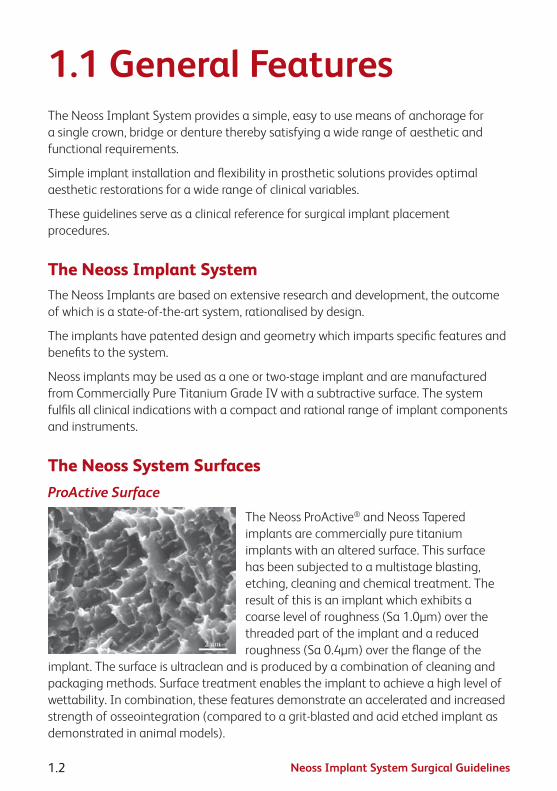
The Neoss ProActive® and Neoss Tapered implants are commercially pure titanium implants with an altered surface. This surface has been subjected to a multistage blasting, etching, cleaning and chemical treatment. The result of this is an implant which exhibits a coarse level of roughness (Sa 1.0µm) over the threaded part of the implant and a reduced roughness (Sa 0.4µm) over the flange of the
implant. The surface is ultraclean and is produced by a combination of cleaning and packaging methods. Surface treatment enables the implant to achieve a high level of wettability. In combination, these features demonstrate an accelerated and increased strength of osseointegration (compared to a grit-blasted and acid etched implant as demonstrated in animal models).

Neoss Implant System Surgical Guidelines 1.3
1.1
Gen
eral
Bimodal Surface
The Neoss Bimodal implant has an altered surface. This surface has been subjected to a multistage blasting and cleaning process during production. The result of this process is a ‘bimodal’ surface which exhibits a coarse level of surface roughness over the threaded body of the implant to optimise bone interlocking and stress distribution. A superimposed fine level of surface
roughness over the entire implant including the cutting faces and the flange increases surface energy and improves wetting by blood and tissue fluids. This ‘ultra clean’ surface is produced by a combination of cleaning and packaging methods.
Neoss System DesignThe Neoss Implant System incorporates TCF geometry combining both Thread Cutting and Thread Forming (TCF) features. This feature results in optimised stability in all bone qualities by a combination of thread cutting and compression thereby optimising stability in poor bone quality and minimising over compression in dense bone.
The implants are ‘double threaded’ and designed with a positive tolerance to achieve compression and increase stability in poor quality bone.
In order to optimise stability and allow seating whilst minimising over compression, a secondary cutting face (TCF design) engages and cuts dense bone areas compensating for the positive tolerance. This extends along the major threaded part of the body depending on the implant type.
These features ensure that optimal stability is achieved. There is a unique relationship between the preparation site, instruments and the geometric features of the Neoss implants and the TCF design. Please refer to the Drilling Sequence Guides and Drill Depth Guides for specific details.
Neoss Esthetiline SolutionThe Esthetiline solution enables simple, rapid and effective anatomical tissue contouring to be developed and optimised with matching chairside and laboratory restorative components in different materials.

Neoss Implant System Surgical Guidelines1.4
1.2 Instrumentation and Component AssortmentThe rationalised design of the Neoss Implant System enables implant placement and restoration to be carried out using the minimum number of components and instruments. Instruments used for implant placement are:
Neoss System Implant KitThe implant is supplied in a kit. This kit is in the form of a ‘sterile blister pack’ and contains the Implant, Cover Screw, Healing Abutments x 2 and Healing Abutment Screw.
All articles within the ‘blister pack’ are STERILE.
The Neoss Implants are packaged in a glass vial with a titanium embedded lid. The implant vial is placed into the Drill/Instrument Organiser for a ‘no touch’ delivery method with the use of the Implant Inserter or Implant Inserter Wrench. The Neoss Implant System is available in 5 diameters Ø3.5, Ø4.0, Ø4.5, Ø5.0 and Ø5.5 and in addition there is a narrow Neoss Ø3.25mm implant. The implants are available in six lengths 7, 9, 11, 13, 15 & 17mm with some deviations, please refer to product catalogue for detailed information about available implant types, diameters and lengths.
Cover screw (included in each implant kit)
The Cover Screw has a low profile and its diameter is the same as the implant-to-abutment connection. The Cover Screw (provided in the implant kit) is placed in the Drill/Instrument Organiser for easy pick-up and torqued to a maximum of 10 Ncm.
Note: Cover screw for Ø3.25 implants is color coded in royal blue.
Neoss Implant System Surgical Guidelines 1.5
1.2
Inst
rum
ents
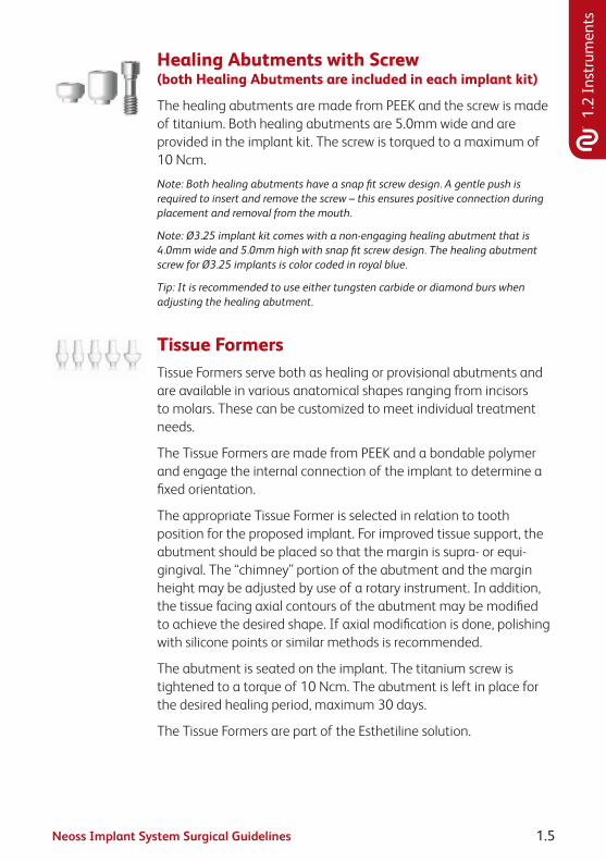
Healing Abutments with Screw (both Healing Abutments are included in each implant kit)
The healing abutments are made from PEEK and the screw is made of titanium. Both healing abutments are 5.0mm wide and are provided in the implant kit. The screw is torqued to a maximum of 10 Ncm.
Note: Both healing abutments have a snap fit screw design. A gentle push is required to insert and remove the screw – this ensures positive connection during placement and removal from the mouth.
Note: Ø3.25 implant kit comes with a non-engaging healing abutment that is 4.0mm wide and 5.0mm high with snap fit screw design. The healing abutment screw for Ø3.25 implants is color coded in royal blue.
Tip: It is recommended to use either tungsten carbide or diamond burs when adjusting the healing abutment.
Tissue FormersTissue Formers serve both as healing or provisional abutments and are available in various anatomical shapes ranging from incisors to molars. These can be customized to meet individual treatment needs.
The Tissue Formers are made from PEEK and a bondable polymer and engage the internal connection of the implant to determine a fixed orientation.
The appropriate Tissue Former is selected in relation to tooth position for the proposed implant. For improved tissue support, the abutment should be placed so that the margin is supra- or equi-gingival. The “chimney” portion of the abutment and the margin height may be adjusted by use of a rotary instrument. In addition, the tissue facing axial contours of the abutment may be modified to achieve the desired shape. If axial modification is done, polishing with silicone points or similar methods is recommended.
The abutment is seated on the implant. The titanium screw is tightened to a torque of 10 Ncm. The abutment is left in place for the desired healing period, maximum 30 days.
The Tissue Formers are part of the Esthetiline solution.

Neoss Implant System Surgical Guidelines1.6
Drills, Countersinks and Screw TapsNeoss drills are for single use and delivered in a sterile condition for immediate use.
Neoss Countersinks and Screw Taps are for multiple use and delivered in sterile condition for immediate use. Please refer to the Cleaning, Disinfection and Sterilisation section 2.7 in these guidelines for cleaning and re-sterilisation.
Please refer to the Drilling Guides in section 1.4 for recommended drills for the placement of different Neoss implant diameters and types.
Note: Tapered drills and countersinks are laser marked with a ‘T’ on the shaft for identification.
Drill ExtenderThe Neoss System Drill Extender has an extension length of 17mm and subsequently will extend 32mm drills to 49mm.
Direction Depth Gauge (4 pcs)The Neoss System Direction Depth Gauge is a multi purpose instrument. It has 2mm and 3mm tips which can be used to measure the depth of the osteotomy during preparation – depth markings are also visible on an x-ray. It can also be used directly in an osteotomy as an alignment pin when placing multiple implants. In addition the threaded portion enables it to be screwed into the implant to assist in multiple placement alignment. It is also equipped with a hole for a floss ligature.
Note: The 3mm tip cannot be used for depth purposes in conjuction with the Twist Drill, Tapered Ø3.0.

Neoss Implant System Surgical Guidelines 1.7
1.2
Inst
rum
ents
Implant InserterThe Neoss Implant System Inserter engages the internal connection of the implant in a ‘no touch’ delivery method direct from the glass vial. The tip of the inserter also engages the cover screw to facilitate placement.
Note: Should the cover screw be inadvertently over tightened with the implant inserter and it ‘spins’ within the connection then ‘stripping’ or ‘rounding out’ the connection has not occurred. The unique design of the implant inserter does not engage the entire width of the connection allowing for removal with the Neoss System screwdriver should over tightening occur.
Note: For optimal alignment of selected abutments and minimal preparation, use the inserter cams to index the implant, i. e. position a cam and an implant groove in the buccal lingual direction.
It is available in three lengths 17, 22 and 32mm and for Ø3.25mm implants in 32mm.
Note: The inserter for Ø3.25mm implant is laser marked Ø3.25 and colour coded in royal blue for easier identification.
Implant Inserter WrenchThe Inserter Wrench is used for manual insertion of the implant. It is used in conjunction with the ratchet. The tip of the inserter also engages the cover screw to facilitate placement. It is available in three lengths 15, 22 and 32mm and for Ø3.25mm implants in 32mm.
Note: Laser markings on the top surface indicate the cam positions of the inserter wrench and makes it easier to index the implant if applicable.
Note: The inserter wrench for Ø3.25mm implant is laser marked Ø3.25 and colour coded in royal blue for easier identification.
Bone MillThe Bone Mill comprises of two parts: the cylinder, which is used for guidance and as depth stop, and the trephine. The parts are supplied sterile.
It is recommend to use the Bone Mill at second stage surgery or whenever the possibility exists that bone may interfere with the correct seating of a Healing Abutment or definitive abutment.

Neoss Implant System Surgical Guidelines1.8
After the implant has been exposed, the guide cylinder is screwed onto the implant by using the screwdriver (in conjunction with the Manual Handle) and tightened to a maximum of 10 Ncm.
The trephine is then placed either in the hand piece or in the Manual Handle then positioned over the cylinder and rotated to clear bone from around the implant. If using a motor then a maximum of 40 rpm is recommended.
The correct depth is achieved by the design compatibility of the cylinder and the trephine.
Note: Only use the guide cylinder which corresponds to the 6mm Healing Abutment.
Neoss System ScrewdriverThe machine screwdrivers are to be used in a handpiece for machine use or in conjunction with the Manual Handle for manual use. It is recommended to use the 15mm Manual Screwdriver in conjunction with the ratchet. Machine screwdrivers are available in 22 and 32mm lengths suitable for all implant diameters.
Note: There is only ONE screwdriver connection in the Neoss System assortment which is used for all screws – Access Abutment components, Cover Screws, Provisional Screws, Impression Coping Screws, Laboratory and Neoss Abutment Screws.
Manual HandleThe Manual Handle can be used to transform a machine screwdriver into a hand screwdriver. It is not recommended to use the manual handle with the Implant Inserters in conjunction with the ratchet as overtorquing may damage the inserter.
RatchetThe torque ratchet is designed for the controlled manual insertion of implants and tightening abutment screws under a defined torque. The appropriate instrument (i.e. Manual Handle or Wrench Inserter) is inserted and carried by the ratchet head.

Neoss Implant System Surgical Guidelines 1.9
1.2
Inst
rum
ents
Titanium Healing AbutmentsAvailable in heights 2, 4, 6, 8 & 10mm, they have a diameter of 4.0mm and are sold separately in a sterile pack. They are used in conjunction with the screwdriver and are tightened to a maximum of 10 Ncm.
Impression Coping and ReplicaThe impression coping is designed for open tray or closed tray impression and is packaged with the implant replica. The impression coping is available in 8, 11 and 18mm lengths. It is also available in an 8mm length to the Access abutment and 11mm to the Ø3.25mm implant.
Note: If the impression screw engages the implant then the coping should be correctly seated. In case of uncertainty radiographic verification is recommended.
Note: The impression coping for Ø3.25mm implant is colour coded in royal blue.
Note: Impression coping in 13mm for open tray impression is available for situations when increased retention is required.
Please refer to the Neoss Implant System Laboratory or Restorative Guidelines for detailed information on both open and closed impression techniques.
Tissue FormersTissue Formers serve both as healing or provisional abutments and are available in various anatomical shapes ranging from incisors to molars. These can be further customized to meet individual treatment needs.
The Tissue Formers are made from PEEK and a bondable polymer and engage the internal connection of the implant to determine a fixed orientation.
The Tissue Formers are part of the Esthetiline solution.

Neoss Implant System Surgical Guidelines1.10
Provisional Titanium AbutmentsThe Provisional Titanium Abutments are designed with a 0.7mm collar and and are available both for single unit (Mono) and multiple unit (Multi) situations. The Provisional Abutment Multi can be used both on implant and Access level with appropriate screws. The Provisional Titanium Abutments may also be used for wax-up and scanning. They also have a flat side for anti-rotation of the crown. Please refer to the Neoss Implant System Laboratory and Restorative Guidelines for detailed information on use of the Provisional Titanium Abutments.

Neoss Implant System Surgical Guidelines 1.11
1.3
Asse
ssm
ent
1.3 Clinical AssessmentPre-operative ExaminationPre-operative examination includes a general evaluation of the patient’s health, a clinical and a radiographic examination.
Attention is paid to the soft and hard tissues, dental history, restorative status and occlusion. Radiographic analysis provides an evaluation of the anatomy, evidence of pathology and bone quantity and an indication of bone quality. Initial radiographic evaluation and clinical assessment in conjunction with dedicated Neoss X-ray Planners can provide an indication of the suitability or not of a patient for treatment with implants.
Implant diameter (mm)Neoss ProActive® and
Bimodal implants flange diameter (mm)
Neoss Tapered implants flange diameter (mm)
Ø3.25 Ø3.5 –
Ø3.5 Ø4.0 Ø4.0
Ø4.0 Ø4.0 Ø4.3
Ø4.5 Ø4.5 Ø4.9
Ø5.0 Ø5.0 Ø5.4
Ø5.5 Ø5.5 Ø5.9
If a patient is considered potentially suitable for implant placement at a preliminary examination then further investigations should be undertaken. These will vary depending on the complexity of each individual case. In general however, it is often valuable to produce articulated study casts. These can be used to assess interocclusal and intraocclusal relationships, occlusal guidance and the presence of interferences. Such models can also be used in the fabrication of diagnostic wax-ups, stents and temporary restorations.
Soft and hard tissue stents can also be fabricated from CT data in more complex cases.
Before treatment commences the patient is informed about the results of the pre-operative examination and is given a clear explanation of the proposed treatment, including expected outcomes and risks involved. Patients should indicate their acceptance of treatment by signing an appropriate consent form.

Neoss Implant System Surgical Guidelines1.12
Indications for Implant Treatment• Totallyandpartiallyedentulousmaxillaeandmandible.
Contraindications to Implant TreatmentGeneral contraindications
• Thepatient’smedicalstatusprecludessurgicaltreatment.
• Patientswithmentalpsychosisandunrealistictreatmentexpectations.
• Alcoholanddrugabuse.
• Aswellastheabovelistedcriteria,considerationshouldalsobegiventocontraindications for implant placement as published in numerous reference books readily accessible to healthcare professionals.
• Insufficientsizeornumbersofimplantstosupportbiomechanicalloadsorundesirable positioning of implants can lead to mechanical failures including fatigue fracture of implants, abutments or abutment screws. Such an example is a narrow diameter implant in combination with angulated abutments in the posterior region.
Local contraindications:
• Thereisinadequatebonequantityandqualitytoallowimplantinstallation.
• Clinicalorradiographicsignsofpathologyinthejaw.
Implant-Bone RelationshipThe implant site must be prepared in such a way that:
• theimplantcanbeplacedinasimpleway
• theinstalledimplantachievesahighlevelofprimarystability
• thereisnodamagetovulnerableareasoflocalanatomyincludingthemaxillary sinus, nasal floor and inferior dental canal
• thereisnodamagetothebonebyoverheatingortrauma
Factors influencing the implant-bone relationship are:
• bonequantity
• bonequality

Neoss Implant System Surgical Guidelines 1.13
1.3
Asse
ssm
ent
• diameterofthedrilledimplantsite
• depthofthedrilledimplantsite
• cuttingandcompressionpropertiesoftheimplant
• useofacountersinkorscrewtap
Bone QualityDense, compact bone provides good immediate support for the installed implant, whilst more open trabecular bone may not provide an optimal level of primary stability at placement. Very dense bone may however, suffer from a restricted blood supply and compromise vitality.
Reduced bone quality combined with reduced bone quantity might be a contraindication for the placement of implants. Planning prosthetic and restorative treatment including the type and design of the prosthesis, must be related and planned with regard to these factors. Bone quality also varies from person to person, jaw to jaw and within the same jaw.
Bone QuantityThe amount of bone available for implant retention differs from person to person, jaw to jaw and also between different areas in the same jaw. Due to degenerative processes in the alveolar bone, edentulous areas resorb in both vertical and horizontal directions.
Anatomical structures such as the maxillary sinuses and the nasal floor give little room for resorption in the upper jaw before the implant support is compromised. In the lower jaw the posterior areas are frequently left without implant installation because of the close relation to the inferior alveolar nerve.
Horizontal resorption may leave too narrow alveolar crest and also lead to the implant being placed in an unfavourable direction.

Neoss Implant System Surgical Guidelines1.14
1.4 Clinical TreatmentPre-operative Handling1. Proper planning before surgery and correct preparation of the implant site ensures
efficient and accurate installation. It is also expected that clinicians working with the Neoss Implant System have a good understanding of the principles of implant surgery and the restorative phase. Access for the surgical instrumentation should be determined before starting the procedure.
2. Premedication is given based on individual indications. Typically, non-allergic patients may be given a 3g sachet of amoxycillin one hour before implant placement and 250mg four times daily post treatment for one week prophylactically.
3. Local anaesthesia is given in desired areas. Additional anaesthesia is given during surgery when needed.
4. Mouth-rinsing with 0.2% chlorhexidine solution for 1 minute.
5. The areas around the mouth are cleaned with 0.2% chlorhexidine solution and the patient is draped with sterile operating sheets covering the body and the head.
Preparation of the Implant Site1. The surgical site is exposed by an incision
on top of the alveolar ridge or placed remote from the crest as judged by the surgeon to be the most adequate way of performing the operation.
2. A buccal and a lingual mucoperiosteal flap are elevated. The incision and flap elevation are extended to enable easy access to/and control over the implant sites and to permit satisfactory registration of the jaw morphology.

Neoss Implant System Surgical Guidelines 1.15
1.4
Trea
tmen
t
3. The positions of the implant sites are determined and can be marked on the bone with a round bur, lance drill or the 2.2mm twist drill. Incremental site preparation is carried out as recommended in the Neoss Implant System Drilling Guides (on the following page). Recommended speed for drills is 800–2000 rpm using lower speed for larger drills, 800 rpm for countersinks and 20 rpm for screw taps.
Hint: If the alveolar ridge is knife-edged and too narrow it is suggested that the ridge is reduced with a bur or a bone file until at least 1mm bone tissue is available to circumscribe the implant.
The ideal distance between each implant is 3.5–4.0mm which gives a minimum centre to centre distance of 7.0mm.
Angulation can be checked with the Direction Depth Gauge after preparation with either the 2.2mm or 3.0mm Twist Drill.
Hint: Pre-operative clinical and radiographic evaluations, together with the established overview of the jaw morphology, now play important roles in the decision-making process.
In partially edentulous situations the position of the implants and their relationship to the remaining dentition must be considered.
All preparation of the bone tissue is carried out under profuse irrigation with saline and using an intermittent drilling technique. This prevents overheating the bone and creates a pumping effect for efficient removal of bone debris.
The instruments can be placed in sterile solution (saline) during surgery if the instruments are used for more than one preparation.
Drill Depth GuidesThis guide shows an 11mm implant in relation to a twist drill and depth guide. Please note actual distance to drill tip is 0.8mm longer than the reference line.
Note: Depth markings on Lance Drill at 3, 5 and 7mm, and at 7 and 9mm on Pilot Drill.
Note: The 3mm tip cannot be used for depth purposes in conjuction with the Twist Drill, Tapered Ø3.0.

Neoss Implant System Surgical Guidelines1.16
Drilling Guide, Neoss ProActive® and Bimodal implants
II I
Ø2.2
Ø3.0
Ø3.2
Ø3.4
Ø3.6
Ø3.9
Ø4.1
Ø4.4
Ø4.6
Ø4.9
Ø5.1
ProActive/BimodalImplant
Ø3.5 mm
ProActiveImplant
Ø3.25 mm
ProActive /BimodalImplant
Ø4.0 mm
ProActive /BimodalImplant
Ø4.5 mm
ProActive /BimodalImplant
Ø5.0 mm
ProActive /BimodalImplant
Ø5.5 mm Drill Stop
Countersink
Screw Tap
Ø3.5Optional use
Ø3.25Optional use
Ø3.5Optional use
Ø3.25Optional use
Ø4.0Optional use
Ø4.0Optional use
Ø4.5Optional use
Ø4,5Optional use
Ø5.0Optional use
Ø5.0Optional use
Ø5.5Optional use
Ø5.5 Optional use
Bone quality Regular Dense
Ø 2.85
Drill protocol notes:
The Neoss drill assortment allows for individualised drill protocol in Soft bone.
Drill step for Regular bone recommended before drill step for Dense bone.
Screw taps available but not required.

Neoss Implant System Surgical Guidelines 1.17
1.4
Trea
tmen
t
Drilling Guide, Neoss Tapered Implants
IV & III II I
Ø2.2
Ø3.0 T
Ø3.2
Ø3.4 T
Ø3.6
Ø3.9 T
Ø4.1
Ø4.4 T
Ø4.6
Ø4.9 T
Ø5.1
TaperedImplant
Ø3.5 mm
TaperedImplant
Ø4.0 mm
TaperedImplant
Ø4.5 mm
TaperedImplant
Ø5.0 mm
TaperedImplant
Ø5.5 mm Drill Stop
Countersink
Screw Tap
Ø3,5 TOptional use
Ø3,5Optional use
Ø4,0 TOptional use
Ø4,0Optional use
Ø4,5 TOptional use
Ø4,5Optional use
Ø5,0 TOptional use
Ø5,0Optional use
Ø5,5 TOptional use
Ø5,5 Optional use
Bone quality Soft Regular Dense
Drill protocol notes:
The Tapered implant allows for further under-preparation in Soft bone.
Drill step for Soft bone not intended for Regular and Dense bone.
Drill step for Regular bone required before drill step for Dense bone.
Drill step for Dense bone does not require drilling to full depth.
Screw taps available but not required.
Twist drill Ø2.2, Dense bone drills and screw taps in the Neoss Tapered implant drill protocol are the same bone cutting instruments as used for Neoss ProActive® implant drill protocol.

Neoss Implant System Surgical Guidelines1.18
Neoss System Implant Insertion – MachineAfter careful preparation of the surgical site the implant is inserted as follows:
1. The implant vial stands in the space provided in the Clinical Organiser. The lid is unscrewed to expose the implant contained in the glass vial.
2. The implant is handled and installed by means of an Implant Inserter. It is available in three lengths 17, 22 and 32mm and for Ø3.25mm implants in 32mm.
3. The Implant Inserter is placed into the implant and manually rotated to engage the internal connection design of the implant. To ensure proper carrying capacity the inserter is then lightly pushed into the implant before being lifted out of the vial.

Neoss Implant System Surgical Guidelines 1.19
1.4
Trea
tmen
t
4. The machine installation of the implant is carried out at low speed – recommended maximum of 20 rpm. Torque control can be used – a maximum of 45 Ncm is recommended.
Note: Use the inserter cams to index the implant if applicable.
Note: It is not recommended to use the Manual Handle with the Machine Implant Inserters in conjunction with the ratchet as excessive torque values may be reached damaging the Manual Handle.
5. If desired use the ratchet in conjunction with the Implant Inserter Wrench for the final levelling of the implant. Grip the shaft close to the centre. Use only light finger force. Excessive torque must not be applied using the ratchet wrench.
Tip: The Implant Inserter or Implant Inserter Wrench can simply be lifted out of the implant following placement. A gentle sideways ‘rock’ of the handpiece will release the inserter easily from the implant. It does not require unscrewing.
Neoss Implant Insertion – ManualAfter careful preparation of the surgical site the implant may also be manually inserted as follows:
1. The implant vial will stand in the space in the Clinical Organiser. The lid is unscrewed to expose the implant contained in the glass vial.

Neoss Implant System Surgical Guidelines1.20
2. Only the Implant Inserter Wrench is used in conjunction with manual insertion and the ratchet. It is available in three lengths 15, 22 and 32mm and for Ø3.25mm implants in 32mm.
3. The Implant Inserter Wrench is placed into the implant and rotated to engage the internal connection design of the implant. To ensure proper carrying capacity the inserter is then lightly pushed into the implant before being lifted out of the vial.
4. Insertion may be carried out with the use of the Implant Inserter Wrench or in combination with the ratchet.
5. For the final levelling of the implant use the ratchet in combination with the Implant Inserter Wrench. Grip the shaft close to the centre. Use only light finger force. Excessive torque applied using the ratchet wrench must be avoided.
Note: Laser markings on the top surface indicate the cam positions of the inserter wrench and makes it easier to index the implant if applicable.

Neoss Implant System Surgical Guidelines 1.21
1.4
Trea
tmen
t
Single Stage Surgical ProcedureHint: For a one stage procedure the implant is commonly inserted so that the flange is positioned above the alveolar crest.
1. After final positioning of the implant the appropriate Healing Abutment (2.7 or 5mm, only 5mm for Ø3.25 implant) (provided in the Implant Kit) is placed and retained with the Healing Abutment Screw (also provided in the Implant kit) tightened up to a maximum of 10 Ncm.
Note: The healing abutments are made of PEEK and may easily be adjusted by grinding with a bur.
Alternatively a Titanium Healing Abutment of the desired length (2, 4, 6, 8, 10mm) or a Tissue Former may be used.
Note: Please refer to the Neoss Implant System Laboratory and Restorative Guidelines for detailed information about construction of provisional crown/bridge.

Neoss Implant System Surgical Guidelines1.22
Two Stage Surgical ProcedureHint: For a two stage procedure the implant is commonly inserted so that the flange is in level with the alveolar crest in an edentulous site, or 2–3mm subcrestal in an extraction site.
First Stage Surgery
1. After implant insertion the Cover Screw (provided in the Implant Kit) is picked up from the Clinical Organiser with the Implant Inserter or the screwdriver.
Note: Does not apply to Implant Inserter for Ø3.25 implant.
2. The Cover Screw is tightened down firmly onto the implant at a torque not exceeding 10 Ncm.
3. The surgical site is then closed in the normal manner.
Note: Please refer to the Post Operative Care recommendations on the following page.
Second Stage Surgery
1. After the healing period a surgical procedure is performed to expose the implants. The Cover Screw is removed with the screwdriver in conjunction with the Manual Handle.
A healing abutment or provisional abutment, including Tissue Former, may be placed as per the instructions as outlined in the Single Stage Procedure of these guidelines.

Neoss Implant System Surgical Guidelines 1.23
1.5
Care1.5 Post Operative Care
One week following the operation the patient is recalled for routine post operative checks. The sutures are removed at this time and the surgical site is checked for complete soft-tissue healing over the implants or around the healing abutment for the 1-stage protocol.
If the patient is wearing a removable prosthesis it is relieved from any compression over the implant site, relined and delivered back to the patient.
The healing period for osseointegration varies but is dependent on certain criteria:
• initialstabilityofimplantattimeofplacement
• bonequality
• graftedbone
• overallpatienthealth
• expectedmasticatoryforces
Generally the principles followed are for the Mandible a minimum of 3 months and in the Maxilla at least 6 months.
Published data however shows excellent long term success with immediate loaded implants, and implants loaded at approximately 6–8 weeks. The decision as to when to load any implants should be assessed at the time of surgical placement and based on the known criteria.
The Neoss System implants may be loaded at any time – immediately, 6–8 weeks or after such time as the surgical clinician deems appropriate based on their experience and the abovementioned criteria.
The patient is reviewed during the healing phase.
Neoss Implant System Surgical Guidelines1.24
1.6 Notes

Neoss Implant System Surgical Guidelines 1.25
1.6
Not
es

Neoss Implant System Surgical Guidelines1.26
Disclaimer of LiabilityNeoss products may only be used according to the manufacturers’ instructions and recommendations.
The user of Neoss products should determine their suitability for particular patients and indications.
Neoss Limited disclaims any liability, expressed or implied, and shall have no responsibility for any direct, indirect, punitive or other damages arising out of or in connection with any errors in professional judgement or practice in the use or placement of the Neoss products.
Caution: Federal (USA) law restricts this device to sale by or on the order of a licensed dentist or physician.
The Neoss Implant System has not been evaluated for safety and compatibility in the Magnetic Resonance environment. The Neoss Implant System has not been tested for heating or migration in the Magnetic Resonance environment.
Copyrights, design rights and trademarks.
Neoss documents, software and designs may not be reprinted, copied or published in whole or part, without the written authorisation of Neoss Limited.
ISO 13485:2003 MD 75473
0086
The Neoss implant assortment has FDA clearance for immediate placement and function recognizing sufficient bone stability and appropriate occlusal loading to restore chewing function.
Document #10501 12-03

Assistant Guidelines


Neoss Implant System Assistant Guidelines 2.1
Cont
ents
Contents
Assistant Guidelines2.1 Assistant Guidelines 2.2
2.2 Treatment Options 2.4
2.3 Surgery Set-up 2.5
2.4 Surgical Procedure 2.9
2.5 Drilling Guides 2.10
2.6 Surgical Drills 2.12
2.7 Cleaning, Disinfection, Sterilisation and Storage 2.17
2.8 Oral Hygiene and Patient Care 2.20
2.9 Packaging Symbols 2.21
2.10 Notes 2.22

Neoss Implant System Assistant Guidelines2.2
2.1 Assistant GuidelinesThe Neoss Implant System comprises implants and abutments offering a logical and simplified approach for all treatment protocols including immediate and early loading, immediate placement and one or two stage placement. The Neoss Implant System is available in 5 diameters Ø3.5, Ø4.0, Ø4.5, Ø5.0 and Ø5.5 and in addition there is a narrow Neoss Ø3.25mm implant. The implants are available in lengths from 7–17mm with some deviations, please refer to product catalogue for detailed information about available implant types, diameters and lengths. The packaging for Neoss implants and instruments used for a specific implant diameter (countersinks and screwtaps) have the following colour coding:
Ø3.25mm Royal Blue Ø3.5mm GreenØ4.0mm YellowØ4.5mm BlueØ5.0mm PeachØ5.5mm Lilac
The Neoss implants are a universal design for all bone qualities. The implants have both Thread Cutting and Thread Forming as the geometry of the implants ‘forms’ the site in poorer bone qualities optimising compression. They are self tapping implants with the primary cutting face designed to cut a precise thread profile and a secondary cutting face to control compression in dense bone.
The Neoss Bimodal implant has an altered surface structure. It is an ‘Ultra Clean’ surface. The modified Bimodal surface is created through ‘blasting’ techniques which are non-detrimental to the material properties. The Neoss ProActive® and Neoss Tapered implants are commercially pure titanium implants with an altered surface. This surface has been subjected to a multistage blasting, etching, cleaning and chemical treatment.
The Neoss implants have an internal connection. The implant is ‘picked up’ from a sterile glass vial with an Implant Inserter. The surgical drills are for single use and delivered in sterile condition for immediate use. There is only one screwdriver connection in the assortment and this is used for all components including cover screws, healing abutment screws, and final abutment screws.
All Neoss implants, except Ø3.25, have a single abutment connection as there is a single platform for all standard implant diameters.
Neoss implants are provided in kits which include a cover screw, two healing abutments (only 5mm with Ø3.25mm implant) and a healing screw. This complete
Neoss Implant System Assistant Guidelines 2.3
2.1
Assi
stan
t Gui
delin
es
delivery method enables the clinician to undertake either one or two stage surgery at time of placement without the need to have pre-ordered individual components. There are also two stickers provided in the implant kit to assist in recording information on the patient’s chart.
The following information is a guide as requirements may vary on an individual basis.

Neoss Implant System Assistant Guidelines2.4
2.2 Treatment OptionsThe Neoss implants may be placed using a Single/One Stage Surgical Protocol (which may involve immediate loading/function) or a Two Stage surgical protocol.
Either surgical protocol may be used to construct a single tooth, bridge or overdenture. Factors which may influence the choice of one protocol over the other are detailed in the Neoss Implant System Surgical Guidelines.
• Single/OneStageSurgery–thisprocedureinvolvesplacingahealingabutment,a provisional abutment or prosthesis at time of implant placement.
• TwoStageSurgery–thisprocedureinvolvesplacingacoverscrewatthetimeof implant placement, then after a designated healing time a second surgical procedure to uncover the implant and place a healing/provisional or other form of abutment.
Prior to the actual procedure, treatment objectives and goals should have been discussed with the patient and careful planning in relation to the number and diameter of implants have been determined.

Neoss Implant System Assistant Guidelines 2.5
2.3
Surg
ery
Set-
up
2.3 Surgery Set-upEither an operating theatre or a well prepared dental surgery may be used for the procedure.
Suggested surgical items/instruments – GENERAL:
• caps,gloves,gownsandmasks
• drapesforpatient
• additionaldrapesforbenchtops,standsetc
• suctionequipment
• irrigationequipment
• antisepticsolution/clampandswabsforpatientpreparation
• surgicalinstruments:scalpels,mirror,bowl,cheekretractors,elevators,scissors–dissecting/suture, forceps, artery forceps
• gauze,gauzeswabsetc
• tubingcovers
• anaesthetic/syringe
• drillingequipment,handpieceandmotor
Suggested surgical items/instruments – NEOSS SYSTEM (please refer to flowchart on the following pages):
• drillkit,optionaldrills,countersink,screwtap
• implants
• pre-sterilisedclinicalorganiser
• NeossSystemsurgicalinstruments:drillextender,inserters17/22/32mm(Ø3.25mm 32mm), inserter wrench 15/22/32mm (Ø3.25mm 32mm), Neoss screwdrivers 22/32mm, 15mm manual screwdriver, manual handle, ratchet, direction depth gauges
• NeossSystemTray(fitstheclinicalorganiser.Usedforsterilisingandstoringinstruments)

Neoss Implant System Assistant Guidelines2.6
Drilling Sequence
#21130#21131#21132#21133#21134#21135
#21181#21182#21183#21184#21185#21186
#21136#21137#21138#21139#21140#21141
#21187#21188#21189#21190#21191#21192
#21142#21143#21144#21145#21146#21147
#21193#21194#21195#21196#21197#21198
#21160#21161#21162#21163#21164
#21199#21200#21201#21202#21203
#21150#21151#21152#21153
#21205#21206#21207#21208
ImplantsBimodal ProActive
Ø3.5
Ø4.0
Ø5.0
Ø5.5
Ø3.25
Ø2.2 Ø3.0
Ø3.0
Ø3.6
Ø3.6
Ø4.4
Ø4.4
Ø4.9
Ø2.2
#21176#21177#21178#21179
9mm11mm13mm15mm
7mm 9mm11mm13mm15mm17mm
7mm 9mm11mm13mm15mm17mm
7mm 9mm11mm13mm15mm17mm
7mm 9mm11mm13mm15mm
7mm 9mm11mm13mm
7mm 9mm11mm13mm
7mm 9mm11mm13mm15mm
7mm 9mm11mm13mm15mm17mm
7mm 9mm11mm13mm15mm17mm
7mm 9mm11mm13mm15mm17mm
Ø3.5
Ø4.0
Ø4.5 Ø4.5
Ø5.0
Ø5.5
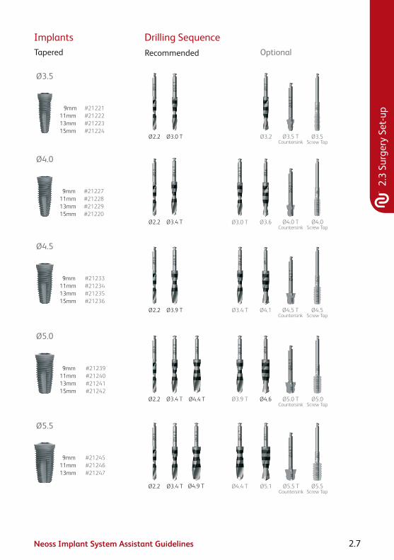
OptionalRecommended
Ø5.1Ø2.2/3.0Pilot Drill
Ø5.5Screw Tap
Ø5.5Countersink
Ø2.2/3.0Pilot Drill
Ø4.6 Ø5.0Screw Tap
Ø5.0 Countersink
Ø3.0
Ø2.2/3.0Pilot Drill
Ø2.2/3.0Pilot Drill
Ø4.5Screw Tap
Ø4.5Countersink
Ø3.6 Ø4.0Screw Tap
Ø4.0Countersink
Ø3.2 Ø3.5Screw Tap
Ø3.5Countersink
Ø4.1
Ø3.25Screw Tap
Ø3.25Countersink
Ø2.2/3.0Pilot Drill
Ø2.2
Ø2.2
Ø2.2
Ø2.2
Ø3.0 Ø3.6 Ø3.9
Ø3.0 Ø3.4
Ø3.0
Ø2.85
Drilling Sequence
#21221#21222#21223#21224
#21227#21228#21229#21220
#21233#21234#21235#21236
#21239#21240#21241#21242
#21245#21246#21247
ImplantsTapered
Ø3.5
Ø4.0
Ø5.0
Ø5.5
Ø2.2 Ø3.4 T
Ø3.4 T
Ø4.4 T
Ø4.4 T
Ø4.9 T
Ø2.2
9mm11mm13mm
9mm11mm13mm15mm
9mm11mm13mm15mm
9mm11mm13mm15mm
9mm11mm13mm15mm
Ø4.5
OptionalRecommended
Ø5.1 Ø5.5Screw Tap
Ø5.5 TCountersink
Ø4.6 Ø5.0Screw Tap
Ø5.0 T Countersink
Ø4.5Screw Tap
Ø4.5 TCountersink
Ø3.6 Ø4.0Screw Tap
Ø4.0 TCountersink
Ø3.2 Ø3.5Screw Tap
Ø3.5 TCountersink
Ø4.1Ø2.2
Ø2.2
Ø2.2
Ø3.4 TØ3.9 T
Ø3.0 TØ3.4 T
Ø3.0 T
Ø3.9 T
Neoss Implant System Assistant Guidelines 2.7
2.3
Surg
ery
Set-
up
Drilling Sequence
#21221#21222#21223#21224
#21227#21228#21229#21220
#21233#21234#21235#21236
#21239#21240#21241#21242
#21245#21246#21247
ImplantsTapered
Ø3.5
Ø4.0
Ø5.0
Ø5.5
Ø2.2 Ø3.4 T
Ø3.4 T
Ø4.4 T
Ø4.4 T
Ø4.9 T
Ø2.2
9mm11mm13mm
9mm11mm13mm15mm
9mm11mm13mm15mm
9mm11mm13mm15mm
9mm11mm13mm15mm
Ø4.5
OptionalRecommended
Ø5.1 Ø5.5Screw Tap
Ø5.5 TCountersink
Ø4.6 Ø5.0Screw Tap
Ø5.0 T Countersink
Ø4.5Screw Tap
Ø4.5 TCountersink
Ø3.6 Ø4.0Screw Tap
Ø4.0 TCountersink
Ø3.2 Ø3.5Screw Tap
Ø3.5 TCountersink
Ø4.1Ø2.2
Ø2.2
Ø2.2
Ø3.4 TØ3.9 T
Ø3.0 TØ3.4 T
Ø3.0 T
Ø3.9 T

Neoss Implant System Assistant Guidelines2.8
Instruments Implant Kit(all implants sold in kits)
Contents of Kit:Implant
Cover ScrewHealing
Abutmentwith Screw
Titanium Healing Abutments
2mm#31159
4mm#31160
6mm#31161
8mm#31162
10mm#31163
Clinical Organisers#51150
#51151
Implant Inserters
17mm #5113722mm #5111832mm #51119
32mm #51142 (Ø3.25)
Screwdrivers
22mm #5113932mm #51140Manual 15mm
#51141
Manual Handle#51126
Drill Extender#41120
Direction Depth Gauge
#51125 pkt of 4
Implant Inserter Wrench
32mm #51132
22mm #51120
15mm #51134
32mm #51143 (Ø3.25)
Ratchet – Torque Driver
#51121
Bone Mill#41138

Neoss Implant System Assistant Guidelines 2.9
2.4
Surg
ical
Pro
cedu
re
2.4 Surgical ProcedureThe surgical procedure may entail a range of procedures including minimally invasive surgery and raising a full thickness flap and exposing the bone in the proposed site. A series of increasing diameter drills are used to enlarge the osteotomy for implant placement – this may involve the use of countersinks and screw taps depending on individual preference and/or the quality of bone.
• Iftheprocedureistobecarriedoutinahospitalenvironmentthenthepreparation of the theatre and surgical staff should conform to the established protocols of each individual hospital.
• Itisdesirabletohavebothasterileandnon-sterileassistantthroughouttheprocedure. Ensure sterile handling during preparation and surgery.
• Allbonepreparationdrillingiscarriedoutunderprofuseirrigationusingeithersaline or sterile water to avoid overheating of the bone.
• Ifasurgicalguide/stentistobeusedforimplantplacementthenfollowthemanufacturer’s recommendation for the sterilisation procedure.
• ThedrillingsequenceforbonepreparationisoutlinedintheNeossSystemDrilling Guides (following pages) however individual preferences or bone quality may require a deviation from these guides. It is therefore recommended that additional/optional components only be opened when indicated by the surgeon.
Note: Please refer to the Neoss Implant System Surgical Guidelines for detailed information in relation to:
• Machineimplantinsertion
• Manualimplantinsertion
• Singlestagesurgicalprocedure
• Twostagesurgicalprocedure
• Postoperativecare

Neoss Implant System Assistant Guidelines2.10
2.5 Drilling GuidesNeoss ProActive® and Bimodal implants
II I
Ø2.2
Ø3.0
Ø3.2
Ø3.4
Ø3.6
Ø3.9
Ø4.1
Ø4.4
Ø4.6
Ø4.9
Ø5.1
ProActive/BimodalImplant
Ø3.5 mm
ProActiveImplant
Ø3.25 mm
ProActive /BimodalImplant
Ø4.0 mm
ProActive /BimodalImplant
Ø4.5 mm
ProActive /BimodalImplant
Ø5.0 mm
ProActive /BimodalImplant
Ø5.5 mm Drill Stop
Countersink
Screw Tap
Ø3.5Optional use
Ø3.25Optional use
Ø3.5Optional use
Ø3.25Optional use
Ø4.0Optional use
Ø4.0Optional use
Ø4.5Optional use
Ø4,5Optional use
Ø5.0Optional use
Ø5.0Optional use
Ø5.5Optional use
Ø5.5 Optional use
Bone quality Regular Dense
Ø 2.85
Drill protocol notes:
The Neoss drill assortment allows for individualised drill protocol in Soft bone.
Drill step for Regular bone recommended before drill step for Dense bone.
Screw taps available but not required.

Neoss Implant System Assistant Guidelines 2.11
2.5
Dril
ling
Gui
des
Neoss Tapered Implants
IV & III II I
Ø2.2
Ø3.0 T
Ø3.2
Ø3.4 T
Ø3.6
Ø3.9 T
Ø4.1
Ø4.4 T
Ø4.6
Ø4.9 T
Ø5.1
TaperedImplant
Ø3.5 mm
TaperedImplant
Ø4.0 mm
TaperedImplant
Ø4.5 mm
TaperedImplant
Ø5.0 mm
TaperedImplant
Ø5.5 mm Drill Stop
Countersink
Screw Tap
Ø3,5 TOptional use
Ø3,5Optional use
Ø4,0 TOptional use
Ø4,0Optional use
Ø4,5 TOptional use
Ø4,5Optional use
Ø5,0 TOptional use
Ø5,0Optional use
Ø5,5 TOptional use
Ø5,5 Optional use
Bone quality Soft Regular Dense
Drill protocol notes:
The Tapered implant allows for further under-preparation in Soft bone.
Drill step for Soft bone not intended for Regular and Dense bone.
Drill step for Regular bone required before drill step for Dense bone.
Drill step for Dense bone does not require drilling to full depth.
Screw taps available but not required.
Twist drill Ø2.2, Dense bone drills and screw taps in the Neoss Tapered implant drill protocol are the same bone cutting instruments as used for Neoss ProActive® implant drill protocol.

Neoss Implant System Assistant Guidelines2.12
2.6 Surgical DrillsThe Neoss Implant System is available in 5 diameters Ø3.5, Ø4.0, Ø4.5, Ø5.0 and Ø5.5 and in addition there is a narrow Neoss Ø3.25mm implant. Neoss Implant System Drill Kits contain the recommended drills for the placement of Neoss ProActive® and Bimodal implants. All Drills, Countersinks and Screw Taps are available separately. Neoss drills are for single use (single patient only) and delivered in a sterile condition for immediate use. If the sterile barrier is broken the drills can be re-sterilised, described in section 2.7.
Article Number Items Included41167 Standard Drill Kit – inc. Twist Drills Ø2.2, 3.0, 3.4, 3.6 & 3.9mm
41168 Supplementary Drill Kit – inc. Twist Drills 2.85, 3.2, 4.1, 4.4, 4.6, 4.9 & 5.1mm
51150 Neoss Clinical Organiser
51151 Neoss Clinical Organiser, Tapered
Note: Tapered drills and countersinks are laser marked with a ‘T’ on the shaft for identification.
Clinical OrganisersThe Neoss Clinical Organisers are designed as three interlocking parts for surgery, instruments and layout. These can be used in combination or individually. Made of highly durable silicone they are easily cleaned and sterilised (100 cycles and up to 1 year).
The layout section on the left provides wells for implant storage, cover and abutment screws on one side and prosthetic components crowns and bridges on the other.
The mid section may be used in combination with the other parts or alone for prosthodontics.
The surgical part of the organiser offers clear markings for drill selection and depth on one side and storage for instruments during sterilisation on the other.
Note: The Neoss Tapered implant organiser is marked ‘Tapered’ to distinguish it from the Neoss ProActive®/Bimodal implant organiser.
Note: It is possible to combine the drill set-up sections for Neoss Tapered and Neoss ProActive®/Bimodal implants.

Neoss Implant System Assistant Guidelines 2.13
2.6
Surg
ical
Dril
ls
Neoss ProActive® and Bimodal implants
Prosthetic setup
Storage and sterilisaton
Surgical setup
Drilling Protocol
Drill depths
Ø3.25
Prosthetic setup
Storage and sterilisaton
Surgical setup
Drilling Protocol
Drill depths
Ø3.25

Neoss Implant System Assistant Guidelines2.14
Neoss Tapered implants
Prosthetic setup
Storage and sterilisaton
Surgical setup
Drilling Protocol
Drill depths
Prosthetic setup
Storage and sterilisaton
Surgical setup
Drilling Protocol
Drill depths
Tapered
Neoss Implant System Assistant Guidelines 2.15
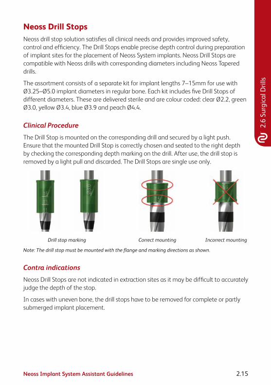
Neoss Drill StopsNeoss drill stop solution satisfies all clinical needs and provides improved safety, control and efficiency. The Drill Stops enable precise depth control during preparation of implant sites for the placement of Neoss System implants. Neoss Drill Stops are compatible with Neoss drills with corresponding diameters including Neoss Tapered drills.
The assortment consists of a separate kit for implant lengths 7–15mm for use with Ø3.25–Ø5.0 implant diameters in regular bone. Each kit includes five Drill Stops of different diameters. These are delivered sterile and are colour coded: clear Ø2.2, green Ø3.0, yellow Ø3.4, blue Ø3.9 and peach Ø4.4.
Clinical Procedure
The Drill Stop is mounted on the corresponding drill and secured by a light push. Ensure that the mounted Drill Stop is correctly chosen and seated to the right depth by checking the corresponding depth marking on the drill. After use, the drill stop is removed by a light pull and discarded. The Drill Stops are single use only.
Drill stop marking Correct mounting Incorrect mounting
Note: The drill stop must be mounted with the flange and marking directions as shown.
Contra indications
Neoss Drill Stops are not indicated in extraction sites as it may be difficult to accurately judge the depth of the stop.
In cases with uneven bone, the drill stops have to be removed for complete or partly submerged implant placement.
2.6
Surg
ical
Dril
ls

Neoss Implant System Assistant Guidelines2.16
Example
Preparing an implant site for a 4 x 11mm implant requires use of Ø2.2, 3.0 and 3.4mm drill stops from Neoss Drill Stop 11mm.
Depth guide

Neoss Implant System Assistant Guidelines 2.17
2.7 Cleaning, Disinfection, Sterilisation and StorageCleaning and Disinfection
• Pre-cleaning and disinfection Instruments (instruments consisting of several parts should be dismantled) drills, countersinks, screw taps and the Clinical Organiser are pre-cleaned immediately after surgery with a brush under running water and/or washer/disinfector and suitable detergent (cleaning and disinfectant solution). They are then rinsed clean (a dishwasher may be used – please follow manufacturer’s recommendations). If not cleaned immediately, soak the components in suitable disinfectant and follow manufacturer’s instructions.
• Cleaning, disinfection and drying The instruments are placed into a glass beaker with a suitable surgical detergent (cleaning and disinfectant solution) and are cleaned in an ultrasonic bath for minimum of five minutes. The Drill/Instrument Organiser may be placed directly into the ultrasonic bath. After ultrasonic cleaning all components are rinsed under running water then dried immediately.
Note: Abutments are processed in the same way after laboratory preparation.
Note: During entire handling the components are placed in an appropriate manner to avoid damage. Components are checked for damage after each procedure and damaged components are removed.
Packaging and Sterilisation• SurgicalinstrumentsspecificfortheNeossSystemarepackagedwiththe
Clinical Organiser in the Neoss System Tray.
• Beforeclinicalusethenon-sterilepartsarerecommendedtobesterilisedthrough autoclaving. For autoclaving, the components should be packaged in a sterilisation bag and autoclaved in a prevacuum cycle at a maximum of 134°C/273°F, exposure time 4–18 min.
Note: Never store instruments while they are still moist or wet. Check all instruments visually. Damaged or blunt instruments should not be used.
StorageSterilised bags are stored in dry environment at room temperature.
2.7
Clea
ning
and
Ste
rilis
atio
n
Neoss Implant System Assistant Guidelines2.18
Neoss Ratchet – Instructions For Use
Page 1 Page 2
10245-4 UK 03-10 © Neoss Limited, 2010, Copyrights, design rights and trademarks,Neoss documents, software and designs may not be reprinted, copied or published in
whole or part, without the written authorization of Neoss Limited.www.neoss.com
Neoss Ltd · Windsor House · Cornwall Road · Harrogate · HG1 2PW · United Kingdom · T +44 1423 817733 · F +44 1423 817744 · E [email protected]
INSTRUCTIONS FOR USE Neoss Ratchet # 51121 The preset torque is set using the adjusting nut (4).
In use when the preset torque is reached the ratchet will ‘break’ at the jointwith an audible click as shown below.
After use, take the ratchet to pieces – this does not require any tools.
Preclean the individual pieces with a soft brush under running water. Avoid the drying of remains of blood and other adhesions.
Following hand rinsing the instruments are placed into a glass beaker with suitable surgical detergent (cleaning and disinfectant solution) and are cleaned in an ultrasonic bath for at least five minutes. Dry the individual parts.
After ultrasonic cleaning all components are rinsed in running water then dried.
Marked areas should be slightly moistened with handpiece maintenance oil.
Assemble ratchet together in a relaxed position. (Setting about 10 Ncm).The labelling ‘IN’ on the ratchet head (1) and scale (6) face the same direction.
The cleaned, dried, oiled and assembled ratchet is placed into a sterilization bag and autoclaved following the manufacturers guidelines.
Caution: Federal (US) law restricts this device to sale by or on order of a licensed dentist or physician.
Care of the Torque Ratchet
Prosthetic Torque function: the desired torque can be adjusted continuously with the adjusting nut (4) via the spring (3). The setting is readable on the scale (6) of the scale capsule (2).
Surgery – locked function: Turn adjusting nut (4) to the graduation ∞. Do not screw in too tightly. Note: the ratchet should always be stored in a relaxed position.
Application
Settings
Do not loosen these screws (2 pcs) since that will lead to loss of the torque functionPin (5)
Torque Adjustment
Ratchet head (1)
Control latch Adjusting nut (4)Scale capsule (2)
Scale (6)
Spring (3)
Thread
Joint
Disc
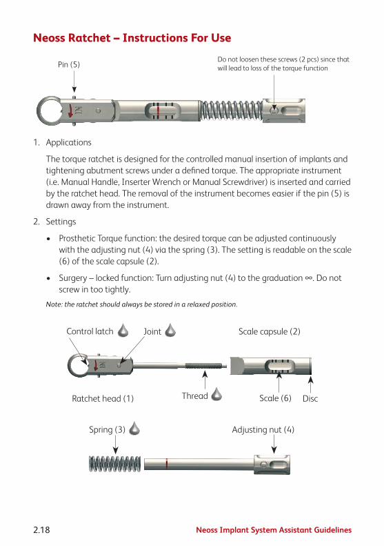
The torque ratchet is designed for the controlled manual insertion of implants and tightening abutment screws under a defined torque. The appropriate instrument (i.e. Manual Handle or Wrench Inserter) is inserted and carried by the ratchet head. The removal of the instrument becomes easier if the pin (5) is drawn away from the instrument.
1. Applications
The torque ratchet is designed for the controlled manual insertion of implants and tightening abutment screws under a defined torque. The appropriate instrument (i.e. Manual Handle, Inserter Wrench or Manual Screwdriver) is inserted and carried by the ratchet head. The removal of the instrument becomes easier if the pin (5) is drawn away from the instrument.
2. Settings
• ProstheticTorquefunction:thedesiredtorquecanbeadjustedcontinuouslywith the adjusting nut (4) via the spring (3). The setting is readable on the scale (6) of the scale capsule (2).
• Surgery–lockedfunction:Turnadjustingnut(4)tothegraduation∞.Donotscrew in too tightly.
Note: the ratchet should always be stored in a relaxed position.
Page 1 Page 2
10245-4 UK 03-10 © Neoss Limited, 2010, Copyrights, design rights and trademarks,Neoss documents, software and designs may not be reprinted, copied or published in
whole or part, without the written authorization of Neoss Limited.www.neoss.com
Neoss Ltd · Windsor House · Cornwall Road · Harrogate · HG1 2PW · United Kingdom · T +44 1423 817733 · F +44 1423 817744 · E [email protected]
INSTRUCTIONS FOR USE Neoss Ratchet # 51121 The preset torque is set using the adjusting nut (4).
In use when the preset torque is reached the ratchet will ‘break’ at the jointwith an audible click as shown below.
After use, take the ratchet to pieces – this does not require any tools.
Preclean the individual pieces with a soft brush under running water. Avoid the drying of remains of blood and other adhesions.
Following hand rinsing the instruments are placed into a glass beaker with suitable surgical detergent (cleaning and disinfectant solution) and are cleaned in an ultrasonic bath for at least five minutes. Dry the individual parts.
After ultrasonic cleaning all components are rinsed in running water then dried.
Marked areas should be slightly moistened with handpiece maintenance oil.
Assemble ratchet together in a relaxed position. (Setting about 10 Ncm).The labelling ‘IN’ on the ratchet head (1) and scale (6) face the same direction.
The cleaned, dried, oiled and assembled ratchet is placed into a sterilization bag and autoclaved following the manufacturers guidelines.
Caution: Federal (US) law restricts this device to sale by or on order of a licensed dentist or physician.
Care of the Torque Ratchet
Prosthetic Torque function: the desired torque can be adjusted continuously with the adjusting nut (4) via the spring (3). The setting is readable on the scale (6) of the scale capsule (2).
Surgery – locked function: Turn adjusting nut (4) to the graduation ∞. Do not screw in too tightly. Note: the ratchet should always be stored in a relaxed position.
Application
Settings
Do not loosen these screws (2 pcs) since that will lead to loss of the torque functionPin (5)
Torque Adjustment
Ratchet head (1)
Control latch Adjusting nut (4)Scale capsule (2)
Scale (6)
Spring (3)
Thread
Joint
Disc
The torque ratchet is designed for the controlled manual insertion of implants and tightening abutment screws under a defined torque. The appropriate instrument (i.e. Manual Handle or Wrench Inserter) is inserted and carried by the ratchet head. The removal of the instrument becomes easier if the pin (5) is drawn away from the instrument.

Neoss Implant System Assistant Guidelines 2.19
2.7
Clea
ning
and
Ste
rilis
atio
n
3. Torque Adjustment
• Thepresettorqueissetusingtheadjustingnut(4).
• Inusewhenthepresettorqueisreachedtheratchetwill‘break’atthejointwith an audible click as shown below.
Page 1 Page 2
10245-4 UK 03-10 © Neoss Limited, 2010, Copyrights, design rights and trademarks,Neoss documents, software and designs may not be reprinted, copied or published in
whole or part, without the written authorization of Neoss Limited.www.neoss.com
Neoss Ltd · Windsor House · Cornwall Road · Harrogate · HG1 2PW · United Kingdom · T +44 1423 817733 · F +44 1423 817744 · E [email protected]
INSTRUCTIONS FOR USE Neoss Ratchet # 51121 The preset torque is set using the adjusting nut (4).
In use when the preset torque is reached the ratchet will ‘break’ at the jointwith an audible click as shown below.
After use, take the ratchet to pieces – this does not require any tools.
Preclean the individual pieces with a soft brush under running water. Avoid the drying of remains of blood and other adhesions.
Following hand rinsing the instruments are placed into a glass beaker with suitable surgical detergent (cleaning and disinfectant solution) and are cleaned in an ultrasonic bath for at least five minutes. Dry the individual parts.
After ultrasonic cleaning all components are rinsed in running water then dried.
Marked areas should be slightly moistened with handpiece maintenance oil.
Assemble ratchet together in a relaxed position. (Setting about 10 Ncm).The labelling ‘IN’ on the ratchet head (1) and scale (6) face the same direction.
The cleaned, dried, oiled and assembled ratchet is placed into a sterilization bag and autoclaved following the manufacturers guidelines.
Caution: Federal (US) law restricts this device to sale by or on order of a licensed dentist or physician.
Care of the Torque Ratchet
Prosthetic Torque function: the desired torque can be adjusted continuously with the adjusting nut (4) via the spring (3). The setting is readable on the scale (6) of the scale capsule (2).
Surgery – locked function: Turn adjusting nut (4) to the graduation ∞. Do not screw in too tightly. Note: the ratchet should always be stored in a relaxed position.
Application
Settings
Do not loosen these screws (2 pcs) since that will lead to loss of the torque functionPin (5)
Torque Adjustment
Ratchet head (1)
Control latch Adjusting nut (4)Scale capsule (2)
Scale (6)
Spring (3)
Thread
Joint
Disc
The torque ratchet is designed for the controlled manual insertion of implants and tightening abutment screws under a defined torque. The appropriate instrument (i.e. Manual Handle or Wrench Inserter) is inserted and carried by the ratchet head. The removal of the instrument becomes easier if the pin (5) is drawn away from the instrument.
4. Care of the Torque Ratchet
In addition to the cleaning, disinfection, sterilisation and storage instructions above please note the following:
• Afteruse,taketheratchettopieces–thisdoesnotrequireanytools.
•
Page 1 Page 2
10245-4 UK 03-10 © Neoss Limited, 2010, Copyrights, design rights and trademarks,Neoss documents, software and designs may not be reprinted, copied or published in
whole or part, without the written authorization of Neoss Limited.www.neoss.com
Neoss Ltd · Windsor House · Cornwall Road · Harrogate · HG1 2PW · United Kingdom · T +44 1423 817733 · F +44 1423 817744 · E [email protected]
INSTRUCTIONS FOR USE Neoss Ratchet # 51121 The preset torque is set using the adjusting nut (4).
In use when the preset torque is reached the ratchet will ‘break’ at the jointwith an audible click as shown below.
After use, take the ratchet to pieces – this does not require any tools.
Preclean the individual pieces with a soft brush under running water. Avoid the drying of remains of blood and other adhesions.
Following hand rinsing the instruments are placed into a glass beaker with suitable surgical detergent (cleaning and disinfectant solution) and are cleaned in an ultrasonic bath for at least five minutes. Dry the individual parts.
After ultrasonic cleaning all components are rinsed in running water then dried.
Marked areas should be slightly moistened with handpiece maintenance oil.
Assemble ratchet together in a relaxed position. (Setting about 10 Ncm).The labelling ‘IN’ on the ratchet head (1) and scale (6) face the same direction.
The cleaned, dried, oiled and assembled ratchet is placed into a sterilization bag and autoclaved following the manufacturers guidelines.
Caution: Federal (US) law restricts this device to sale by or on order of a licensed dentist or physician.
Care of the Torque Ratchet
Prosthetic Torque function: the desired torque can be adjusted continuously with the adjusting nut (4) via the spring (3). The setting is readable on the scale (6) of the scale capsule (2).
Surgery – locked function: Turn adjusting nut (4) to the graduation ∞. Do not screw in too tightly. Note: the ratchet should always be stored in a relaxed position.
Application
Settings
Do not loosen these screws (2 pcs) since that will lead to loss of the torque functionPin (5)
Torque Adjustment
Ratchet head (1)
Control latch Adjusting nut (4)Scale capsule (2)
Scale (6)
Spring (3)
Thread
Joint
Disc
The torque ratchet is designed for the controlled manual insertion of implants and tightening abutment screws under a defined torque. The appropriate instrument (i.e. Manual Handle or Wrench Inserter) is inserted and carried by the ratchet head. The removal of the instrument becomes easier if the pin (5) is drawn away from the instrument.
marked areas should be slightly moistened with handpiece maintenance oil.
• Assembleratchettogetherinarelaxedposition(settingabout10Ncm).Thelabelling IN on the ratchet head (1) and scale (6) face the same direction.
• Thelifetimeoftheratchetisprimarilydependentonusageandnotthenumberof sterilisation cycles.

Neoss Implant System Assistant Guidelines2.20
2.8 Oral Hygiene and Patient CareAs with natural dentition, dental implants/prostheses are susceptible to plaque build-up which may have a detrimental affect on the long term success of the prosthesis. It is therefore of vital importance that the patient is carefully instructed on the importance of regular check-ups and ‘home care’. Following insertion of the final prosthesis the patient should be instructed in the routine for home care.
When instructing patients how to maintain their implant supported prosthesis it should be remembered that some patients may not have had natural teeth for some time. Therefore individualised and thorough instruction on ‘how to clean’ should be developed for each patient. This may include the recommendation of certain toothbrushes, mouth rinses, dental floss or interdental cleaning aids.
Titanium is a soft metal and therefore the use of abrasive toothpastes or instruments which may scratch the abutment should be avoided.
In addition to ‘home care’ it is recommended that the patient be checked regularly in the first 12 months after prosthesis insertion. The dentist would include in the check-up the stability of the prosthesis, the occlusion, surrounding soft tissues and the patient’s ability to maintain a high level of ‘at home’ oral hygiene.

Neoss Implant System Assistant Guidelines 2.21
2.9
Pack
agin
g Sy
mbo
ls
2.9 Packaging SymbolsUSE BY/EXPIRY DATE STERILE
(Contents of inner Package STERILE)
DO NOT RE-USE (Single use only)
NON-STERILE
DATE OF MANUFACTURE LOT/BATCH NUMBER
SEE INSTRUCTIONS FOR USE Caution: Federal (USA) law restricts the sale of this device to or on the order
of a licensed physician or dentist
Rx only

Neoss Implant System Assistant Guidelines2.22
2.10 Notes

Neoss Implant System Assistant Guidelines 2.23
2.10
Not
es

Neoss Implant System Assistant Guidelines2.24
Disclaimer of LiabilityNeoss products may only be used according to the manufacturers’ instructions and recommendations.
The user of Neoss products should determine their suitability for particular patients and indications.
Neoss Limited disclaims any liability, expressed or implied, and shall have no responsibility for any direct, indirect, punitive or other damages arising out of or in connection with any errors in professional judgement or practice in the use or placement of the Neoss products.
Caution: Federal (USA) law restricts this device to sale by or on the order of a licensed dentist or physician.
The Neoss Implant System has not been evaluated for safety and compatibility in the Magnetic Resonance environment. The Neoss Implant System has not been tested for heating or migration in the Magnetic Resonance environment.
Copyrights, design rights and trademarks.
Neoss documents, software and designs may not be reprinted, copied or published in whole or part, without the written authorisation of Neoss Limited.
ISO 13485:2003 MD 75473
0086
The Neoss implant assortment has FDA clearance for immediate placement and function recognizing sufficient bone stability and appropriate occlusal loading to restore chewing function.
Document #10501 12-03

Laboratory Guidelines


Neoss Implant System Laboratory Guidelines 3.1
Cont
ents
Contents
Laboratory Guidelines3.1 Neoss Implant System 3.2
3.2 Restorative Assistants 3.3
3.3 Esthetiline Solution 3.4
3.4 Provisional Abutments 3.9
3.5 Impression Techniques – Implant Level 3.13
3.6 NeoLink™ – the Concept 3.19
3.6.1 Single Unit Construction 3.21
3.6.2 Multiple Unit Construction 3.25
3.6.3 CAD/CAM Solutions 3.29
3.6.4 Direct Investing – Casting 3.31
3.6.5 Indirect Investing – Framework Bonding 3.32
3.7 Titanium Prepable Abutments 3.33
3.8 Zirconia Abutment 3.36
3.9 Express Abutment 3.40
3.10 Access Abutment 3.47
3.11 Overdenture Solutions 3.50
3.12 Technical Data 3.71
3.13 Notes 3.72

Neoss Implant System Laboratory Guidelines3.2
3.1 Neoss Implant SystemThe Neoss Implant System is a logical and simplified approach suitable for all dental implant treatment protocols: Immediate or Early Loading, Immediate Placement and One or Two Stage placement. The Neoss Implant System is available in 5 diameters Ø3.5, Ø4.0, Ø4.5, Ø5.0 and Ø5.5 and in addition there is a narrow Neoss Ø3.25mm implant. The implants are available in lengths from 7–17mm with some deviations, please refer to product catalogue for detailed information about available implant types, diameters and lengths.
The Neoss implants are a universal design for all bone qualities. The implants have both Thread Cutting and Thread Forming as the geometry of the implants ‘forms’ the site in poorer bone qualities optimising compression. They are self tapping implants with the primary cutting face designed to cut a precise thread profile and a secondary cutting face to control compression in dense bone.
The Neoss Bimodal implant has an altered surface structure. It is an ‘Ultra Clean’ surface. The modified Bimodal surface is created through ‘blasting’ techniques which are non-detrimental to the material properties. The Neoss ProActive® and Neoss Tapered implants are commercially pure titanium implants with an altered surface. This surface has been subjected to a multistage blasting, etching, cleaning and chemical treatment.
The Neoss implants have an internal connection. The implant is ‘picked up’ from a sterile glass vial with an Implant Inserter. The surgical drills are for single use and delivered in sterile condition for immediate use. There is only one screwdriver connection in the assortment and this is used for all components including cover screws, healing abutment screws, and final abutment screws.
All Neoss implants, except Ø3.25, have a single abutment connection as there is a single platform for all standard implant diameters. The abutment connection has zero rotation preventing abutment loosening and external wall deformation.
Neoss implants are provided in kits which include a cover screw, two healing abutments (only 5mm with Ø3.25mm implant) and a healing abutment screw. This complete delivery method enables the clinician to undertake either one or two stage surgery at time of placement without the need to have pre-ordered individual components.
The following information is a guide as requirements may vary on an individual basis.
Neoss Implant System Laboratory Guidelines 3.3
3.2
Rest
orat
ive
Assi
stan
ts
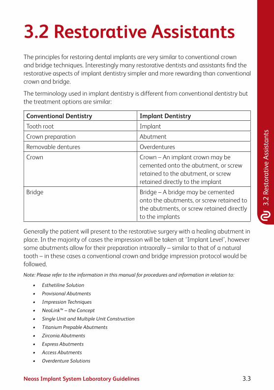
3.2 Restorative AssistantsThe principles for restoring dental implants are very similar to conventional crown and bridge techniques. Interestingly many restorative dentists and assistants find the restorative aspects of implant dentistry simpler and more rewarding than conventional crown and bridge.
The terminology used in implant dentistry is different from conventional dentistry but the treatment options are similar:
Conventional Dentistry Implant DentistryTooth root Implant
Crown preparation Abutment
Removable dentures Overdentures
Crown Crown – An implant crown may be cemented onto the abutment, or screw retained to the abutment, or screw retained directly to the implant
Bridge Bridge – A bridge may be cemented onto the abutments, or screw retained to the abutments, or screw retained directly to the implants
Generally the patient will present to the restorative surgery with a healing abutment in place. In the majority of cases the impression will be taken at ‘Implant Level’, however some abutments allow for their preparation intraorally – similar to that of a natural tooth – in these cases a conventional crown and bridge impression protocol would be followed.
Note: Please refer to the information in this manual for procedures and information in relation to:
• EsthetilineSolution
• ProvisionalAbutments
• ImpressionTechniques
• NeoLink™–theConcept
• SingleUnitandMultipleUnitConstruction
• TitaniumPrepableAbutments
• ZirconiaAbutments
• ExpressAbutments
• AccessAbutments
• OverdentureSolutions

Neoss Implant System Laboratory Guidelines3.4
3.3 Esthetiline SolutionThe Esthetiline solution enables simple, rapid and effective anatomical tissue contouring to be developed and optimised with matching chair-side and laboratory restorative components. The Neoss Esthetiline solution provides seamless restorative integration all the way from implant placement to final crown restoration. The natural emergence profile developed during healing is matched perfectly in permanent restorative components; Prepable Titanium abutments, Zirconia abutments, custom abutments and copings, and CAD-CAM solutions as shown on next page.
The gingival margin abutment profile is fixed in relation to the non-rotational feature on all Esthetiline abutments and thus related to the position of the implant – indexing. The Esthetiline solution is best applied when the implant is oriented at surgery by ensuring that there is a groove in the buccual direction. This will require the least adjustment. Indexing throughout the treatment is possible utilising the indexing features as shown in the Esthetiline Overview on next page.

Neoss Implant System Laboratory Guidelines 3.5
3.3
Esth
etili
ne S
olut
ion
Soft
Tiss
ue H
ealin
g
Tem
pora
ry S
olut
ions
Impr
essio
n So
lutio
ns
Esth
etic
Res
tora
tion
Esth
etili
ne O
verv
iew Prep
able
Ab
utm
ents
Not
Opt
imal
Opt
imal
Zirc
onia
Abut
men
tsN
eoLi
nk™
Pl
astic
Cop
ings
Set
Neo
Link
™ M
ono
Scre
w R
etai
ned
Cem
ent R
etai
ned/
Cha
irsid
e
Prod
uct A
ssor
tmen
tTr
eatm
ent O
ptio
nsIn
dexi
ng
Tiss
ue Fo
rmer
s
Tiss
ue Fo
rmer
s
Wid
eIn
sicor
Ø3.
5Ø
4.0
Ø4.
5Ø
5.0
Ø5.
5
Nar
row
Insic
orCa
nine
Pre-
mol
arM
olar
9x5x
12x
+

Neoss Implant System Laboratory Guidelines3.6
Esthetiline Shapes
Narrow InsicorWide Insicor
31300 NeoLink™ Plastic Copings Set
Prepable Abutments
Zirconia Abutments
Tissue Formers
Canine Pre-molar Molar
31274
31294
31288
31273
31293
31287
31272
31292
312863128231280
#1 #2 #3 #4 #5 #6 #7 #8 #9 #10 #11 #12
3128331281 31284 31285
31271
31291
31270
31290
Note:PlasticcopingscanbeusedwithaNeoLink™astry-inabutmentstofacilitateabutmentselection.Plastic copings are for single use.

Neoss Implant System Laboratory Guidelines 3.7
3.3
Esth
etili
ne S
olut
ion
Tissue Former – Healing & Provisional Abutment
Placement of Tissue Formers at implant placement or abutment connection guides the soft tissue and enables simple creation of the optimal emergence profile. Tissue formers are non-rotational and made in a range of anatomical shapes which are designed to match the profiles of individual incisor, canine, pre-molar and molar teeth.
Note: The trans-gingival section on Tissue Formers is slightly smaller buccally than matching restorative components in order to provide additional soft tissue volume.
Note: The Tissue Former – Molar can be rotated 90° if preferred but the implant has to be oriented accordingly at the time of surgery.
The Tissue Former may be adjusted as a healing abutment or prepared for a provisional crown or bridge. The PEEK/polymer structure makes it highly biocompatible whilst retaining ease of preparation, strength and ability to bond to crown and bridge resins. For more information about the use of Tissue Formers as healing and provisional abutment please refer to sections 1.4 ‘Clinical Treatment’ and 3.4 ‘Provisional Abutments’.
Impression TechniquesAfter the gingiva has been sculptured with the Tissue Former there are a series of treatment options; an impression may be taken to enable laboratory fabrication of a custom abutment or gold or metal framework in a traditional manner. Prepable Titanium or Zirconia abutments may also be prepared in the laboratory environment. An alternative option is to place a suitable Titanium Prepable or Zirconia Abutment directly at the chair-side and take a conventional crown impression.
Note:ItmayprovenecessarytopreparethemarginsoftheTitaniumPrepableorZirconiaAbutments,formoreinformationpleaserefertosections3.7‘TitaniumPrepableAbutments’and3.8‘ZirconiaAbutment’.
The standard Neoss impression coping is suitable for implant level impressions. There will typically be a gap between the impression coping and the sculpted anatomical gingiva which has been created by the Tissue Former. In the majority of cases the degree of tissue collapse will be minimal during the impression procedure and a normal impression technique syringing material between the coping and gingival will give an accurate result. If there is concern about tissue collapse a second Tissue Former of the same type may be used together with an impression coping screw for the impression. For more information about impression taking procedure please refer to section 3.5 ‘Impression Techniques – Implant Level’.

Neoss Implant System Laboratory Guidelines3.8
Prepable Titanium Abutment
The shape of Prepable Titanium abutments match the profile of the Tissue Formers making it possible to accurately define soft tissue contours without the need for complex impression procedures. The abutments may be modified by marginal adaptation and angulation. For more information about Prepable Titanium Abutments please refer to section 3.7 ‘Titanium Prepable Abutments’.
Zirconia Abutment
Zirconia abutments are supplied in two parts; the Zirconia coping, with a profile matching the provisional Tissue Formers thus giving an optimal aesthetic solution, and a pre-blasted Titanium NeoLink™ Mono. The Zirconia coping is designed to be cemented onto the NeoLink™. This may be carried out at the chair-side or in laboratory using resin bonded cement. Careful adjustment of the ceramic coping may be made prior to cementation and placement. For more information about use of the Zirconia abutment please refer to section 3.8 ‘Zirconia Abutment’.
NeoLink™ Mono and NeoLink™ Plastic Copings
Individual crowns may be constructed utilising the NeoLink™ concept. The set of preformed plastic anatomical copings provide a complete range of abutment designs for different teeth, emergence profiles, heights and angulations. For best result choose the same type of coping matching the used Tissue Former. The different copings represent and correspond to the matching Tissue Formers as shown previously; copings #1–4 Wide Incisor, #5–8 Narrow Incisor, #9–10 Canine, #11 Pre-molar and #12 Molar.
Note:PlasticcopingscanbeusedwithaNeoLink™astry-inabutmentstofacilitateabutmentselection.Plastic copings are for single use.
There is an index between the NeoLink™ and the coping in order to achieve a specific orientation in relation to the implant’s rotational position.
For more information about custom abutments and copings and CAD/CAM solutions please refer to section 3.6 ‘NeoLink™ – the Concept’.

Neoss Implant System Laboratory Guidelines 3.9
3.4
Prov
isio
nal A
butm
ents
3.4 Provisional AbutmentsTissue FormersThe Tissue Former may be used for cement or screw retained provisional restorations. The abutments may be placed directly into the patient’s mouth and prepared intra-orally or adjusted by the technician on a laboratory model. If the Esthetiline Solution is utilised, then the optimal result is achieved by choosing the same type of permanent restoration and same position as during healing.
Screw retained
1. Cut mechanical retention grooves or slots into the Tissue Former.
2. Construct a provisional crown/bridge in conventional manner. Ensure the screw access channel remains clear. Unscrew and remove the provisional abutment and contour margins/polish etc as required.
3. Insert the completed provisional crown/bridge and tighten to 10 Ncm.
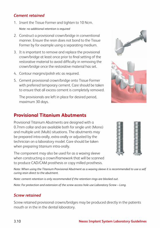
Neoss Implant System Laboratory Guidelines3.10
Cement retained
1. Insert the Tissue Former and tighten to 10 Ncm.
Note: no additional retention is required
2. Construct a provisional crown/bridge in conventional manner. Ensure the resin does not bond to the Tissue Former by for example using a separating medium.
3. It is important to remove and replace the provisional crown/bridge at least once prior to final setting of the restorative material to avoid difficulty in removing the crown/bridge once the restorative material has set.
4. Contour margins/polish etc as required.
5. Cement provisional crown/bridge onto Tissue Former with preferred temporary cement. Care should be taken to ensure that all excess cement is completely removed.
The provisionals are left in place for desired period, maximum 30 days.
Provisional Titanium AbutmentsProvisional Titanium Abutments are designed with a 0.7mm collar and are available both for single unit (Mono) and multiple unit (Multi) situations. The abutments may be prepared intra-orally, extra-orally or adjusted by the technician on a laboratory model. Care should be taken when preparing titanium intra-orally.
The component may also be used for as a waxing sleeve when constructing a crown/framework that will be scanned to produce CAD/CAM prosthesis or copy milled prosthesis.
Note: When using the Titanium Provisional Abutment as a waxing sleeve it is recommended to use a self curing resin direct to the abutment.
Note: cement retention is only recommended if the retention rings are blocked out.
Note: For protection and extension of the screw access hole use Laboratory Screw – Long.
Screw retained
Screw retained provisional crowns/bridges may be produced directly in the patients mouth or in the in the dental laboratory.
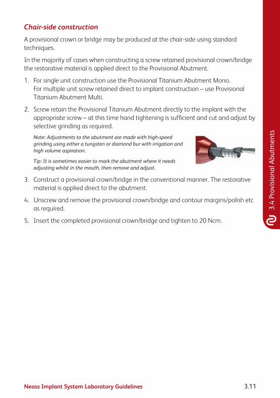
Neoss Implant System Laboratory Guidelines 3.11
3.4
Prov
isio
nal A
butm
ents
Chair-side construction
A provisional crown or bridge may be produced at the chair-side using standard techniques.
In the majority of cases when constructing a screw retained provisional crown/bridge the restorative material is applied direct to the Provisional Abutment.
1. For single unit construction use the Provisional Titanium Abutment Mono. For multiple unit screw retained direct to implant construction – use Provisional Titanium Abutment Multi.
2. Screw retain the Provisional Titanium Abutment directly to the implant with the appropriate screw – at this time hand tightening is sufficient and cut and adjust by selective grinding as required.
Note: Adjustments to the abutment are made with high-speed grinding using either a tungsten or diamond bur with irrigation and high volume aspiration.
Tip: It is sometimes easier to mark the abutment where it needs adjusting whilst in the mouth, then remove and adjust.
3. Construct a provisional crown/bridge in the conventional manner. The restorative material is applied direct to the abutment.
4. Unscrew and remove the provisional crown/bridge and contour margins/polish etc as required.
5. Insert the completed provisional crown/bridge and tighten to 20 Ncm.

Neoss Implant System Laboratory Guidelines3.12
Laboratory construction
Clinical step 1
1. An implant level impression is taken and sent to the laboratory.
Laboratory procedure
In the majority of cases when constructing a screw retained provisional crown/bridge the restorative material is applied direct to the Provisional Abutment.
A. For single unit construction use the Provisional Titanium Abutment Mono. For multiple unit screw retained direct to implant construction – use Provisional Titanium Abutment Multi.
B. Screw retain the Provisional Titanium Abutment/s onto the laboratory model with the applicable screw. Cut and adjust by selective grinding as required.
Note: Adjustments to the abutment are made with high-speed grinding using either a tungsten or diamond bur with irrigation and high volume aspiration.
C. Construct a provisional crown/bridge in the conventional manner. The restorative material is applied direct to the abutment. The surface of the abutment may be roughened or sandblasted to aid in retention of the restorative material.
D. Unscrew and remove the provisional crown/bridge and contour margins/polish etc as required.
E. Return to dentist for insertion.
Clinical step 2
1. The provisional crown/bridge is delivered to the patient and hand-tightened to the implant. Final checking of occlusion/contours/colour is carried out. Once verified the screw is tightened to 20 Ncm.
2. Block out the screw access channel with gutta-percha. Use a suitable material such as light curing composite to fill in the screw access channel.
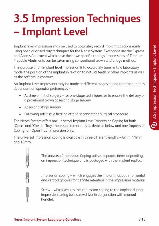
Neoss Implant System Laboratory Guidelines 3.13
3.5
Impr
essi
on T
echn
ique
s –
Impl
ant L
evel
3.5 Impression Techniques – Implant LevelImplant level impressions may be used to accurately record implant positions easily using open or closed tray techniques for the Neoss System. Exceptions are the Express and Access Abutment which have their own specific copings. Impressions of Titanium Prepable Abutments can be taken using conventional crown and bridge method.
The purpose of an implant level impression is to accurately transfer to a laboratory model the position of the implant in relation to natural teeth or other implants as well as the soft tissue contours.
An Implant Level impression may be made at different stages during treatment and is dependant on operator preferences –
• Attimeofinitialsurgery–foronestagetechniques,ortoenablethedeliveryofa provisional crown at second stage surgery
• Atsecondstagesurgery
• Followingsofttissuehealingafterasecondstagesurgicalprocedure
The Neoss System offers one universal Implant Level Impression Coping for both ‘Open’ and ‘Closed’ Tray impression techniques as detailed below and one Impression Coping for ‘Open Tray’ impression only.
The universal impression coping is available in three different lengths – 8mm, 11mm and 18mm.
The universal Impression Coping utilises separate items depending on impression technique and is packaged with the implant replica.
Impression coping – which engages the implant has both horizontal and vertical grooves for definite retention in the impression material.
Screw – which secures the impression coping to the implant during impression taking (use screwdriver in conjunction with manual handle).

Neoss Implant System Laboratory Guidelines3.14
Plastic extension tube– which may be trimmed to length and enables easy access to the head of the screw when using the ‘Open Tray’ technique.
Note: The impression copings are not interchangeable for reasons of accuracy. Hence use the same impression coping in the same impression cavity.
Red Plastic Cap – which is used for closed tray impressions only.
White Plastic Cap – used for auxiliary retention in open tray.
Impression Coping Open Tray.
Neoss Implant Level Impression TechniquesOpen Tray
In an open tray technique the impression coping is ‘picked up’ in the impression material. Only three of the four components of the universal Impression Coping Assembly are used, the Red and White Plastic Caps are NOT used.
Clinical Procedure – Open Tray
1. Use the universal Impression Coping as supplied.
Note: The Neoss Impression coping is ‘self-seating’. This means that the screw will not engage the implant if the coping is not correctly seated. However a radiograph is recommended if there is any uncertainty or risk of soft tissue entrapment.
2. Expose the head of the implant – e.g. remove the cover screw or healing/provisional abutment and ensure that the top of the implant is clear of any soft or hard tissue.
3. Place desired length impression coping (8, 11 or 18mm) (11mm for Ø3.25mm implant) Implant Level impression coping onto the implant and tighten the screw – hand tightening is sufficient, use the screwdriver and manual handle.

Neoss Implant System Laboratory Guidelines 3.15
3.5
Impr
essi
on T
echn
ique
s –
Impl
ant L
evel
4. Try-in the modified impression tray (a window has been previously cut in the area of the implant) and ensure that the tray is clear of the impression coping and the plastic tube extends beyond the impression tray. The plastic tube may be reduced or removed prior to taking the impression. Place some wax over the window.
5. Using a medium to heavy body impression material, inject around the impression coping and fill the impression tray.
6. Seat the impression tray into the patient and ensure the plastic tube/s is clearly visible.
7. After the impression material has set, grasp the plastic sleeve with tweezers and remove.
8. Using the screwdriver ensure that the screw has been completely undone/disengaged from the coping and remove the impression.
Note: Upon removal of the impression the implants are covered by replacing the cover screw or healing/provisional abutment.
9. Using the screwdriver attach the implant replica to the impression coping. Whilst supporting the screw with the screwdriver, ensure correct seating and hand tighten – DO NOT OVER TIGHTEN (10 Ncm maximum).

Neoss Implant System Laboratory Guidelines3.16
Note: The Impression Coping Open Tray utilises same procedure as above.
Impression Coping Cap Open Tray
The Impression Coping Cap Open Tray is used as an option to increase the retention of the impression coping during the open tray impressions.
The cap is aligned and firmly pushed onto the impression coping.
The impression coping is then used in the manner described above for the Neoss open tray impression technique.

Neoss Implant System Laboratory Guidelines 3.17
3.5
Impr
essi
on T
echn
ique
s –
Impl
ant L
evel
Laboratory Procedure – Open Tray
A. Ensure that the implant replica is correctly seated on to the impression coping.
B. Pour model in the usual manner and allow to set.
C. Undo the screw and remove impression from the model.
D. Proceed to construct the prosthesis.
Tip: Soft tissue material may be applied around the impression coping before the model is poured. Another option is to construct the soft tissue model on the master model by injecting soft tissue material into a preprepared ‘putty’ key which has been reseated onto the prepared model.
Neoss Implant Level Impression TechniquesClosed Tray
In a closed tray technique the impression coping remains in the patient’s mouth when the impression is removed. Once the impression coping has been removed and the replica attached it is then re-seated into the impression. The Red Plastic Cap is utilised over the impression coping once it has been correctly seated into the patient’s mouth. The plastic extension tube is NOT used.
Note: This technique may be contraindicated in cases where implant angulation is severe.
Clinical Procedure – Closed Tray
1. Use the impression coping as supplied – however remove the plastic extension tube.
Note: The Neoss impression coping is ‘self-seating’. This means that the screw will not engage the implant if the coping is not correctly seated. However a radiograph is recommended if there is any uncertainty or risk of soft tissue entrapment.
2. Expose the implant – e.g. remove the cover screw or healing/provisional abutment and ensure that the top of the implant is clear of any soft or hard tissue.
3. Place the desired length impression coping (8, 11 or 18mm) (11mm for Ø3.25mm implant) Implant Level impression coping onto the implant and tighten the screw with the screwdriver and manual handle.
Position the Red Plastic Cap on the impression coping and firmly pushed until seated.
Note: The impression cap needs to be properly oriented on the impression coping, the 2 flat vertical sides help orientation so that the cap slides without resistance over the impression coping.

Neoss Implant System Laboratory Guidelines3.18
4. Using a medium to heavy body impression material, inject around the impression coping and fill the impression tray.
5. Seat the impression tray into the patient.
6. When the impression material has set, remove the impression (the Red Plastic Impression Cap is ‘picked up’ in the impression).
7. Using the screwdriver unscrew and remove the Implant Level impression coping from the patient.
8. The implant replica (supplied with the impression coping) is now screwed into the impression coping.
9. Reposition the impression coping with replica attached back into the corresponding location in the Red Plastic Cap in the impression (use the two flat sides of the impression coping for alignment into the Red Plastic Cap).
The impression coping needs to be properly oriented in the Red Plastic Cap, meaning that the coping will slide without resistance almost completely down into the cap before a final push seats the coping.
Laboratory Procedure – Closed Tray
A. Ensure that the implant replica is correctly seated on to the impression coping which has been repositioned accurately into the impression.
B. Pour model in the usual manner and allow to set.
C. Remove impression from the model, undo screw and remove impression coping.
D. Proceed to construct the prosthesis.
Tip: Soft tissue material may be applied around the impression coping before the model is poured. Another option is to construct the soft tissue model on the master model by injecting soft tissue material into a prepared ‘putty’ key which has been reseated onto the prepared model.

Neoss Implant System Laboratory Guidelines 3.19
3.6
Neo
Link
™ –
the
Conc
ept
3.6 NeoLink™ – the ConceptIntroductionThe Neoss Implant System abutments have been designed to facilitate the fabrication of custom designed screw retained gold, titanium and ceramic abutments or frameworks having a precision machined fit which are utilised in the production of cement or screw retained implant prosthesis.
Neoss abutments offer an efficient high accuracy prosthetic solution, whilst ensuring optimum quality control and offering an economical solution with numerous technical benefits.
Abutments and frameworks may be produced in zirconia or other options such as gold, titanium or cobalt chrome, or they may be CAD/CAM produced while maintaining the accuracy and tolerances obtained from machined components. This is possible due to the NeoLink™, which is a precision machined component made of gold, c.p. titanium or cobalt chrome, providing the interface between implant and abutment framework.
The set of preformed plastic anatomical copings, part of the Esthetiline Solution, provide a complete range of abutment designs for different teeth, emergence profiles, heights and angulations.
Once the accuracy of the Neoss replica has been checked on the master model, the choice is made to create a crown (NeoLink™ Mono) or bridge (NeoLink™ Multi) in gold, titanium or cobalt chrome. A custom abutment or framework is produced by combining the most appropriate design of plastic anatomical coping with the desired NeoLink™.
There are a number of options:
1. CAD/CAM abutments/frameworks cemented or bonded to the NeoLink/s™ titanium.
Note: Bonding of CAD/CAM designed copings or frameworks may be done ‘prior to’ or ‘after’ application of the porcelain/restorative material. This depends on the materials and techniques utilised.
2. Invest and cast directly onto the gold NeoLink™ with a suitable alloy.
3. Remove the NeoLink™ from the waxed coping/framework and cast the anatomical coping/framework (in a desired alloy) without the NeoLink™. After proper finishing of the cast coping/framework bond to the NeoLink/s™.
Note: The margin on the titanium abutments is too thin to be used in conjunction with welding a castcoping/frameworktotheNeoLink™.

Neoss Implant System Laboratory Guidelines3.20
Three types of restorations can be produced; a restoration cemented on to custom abutments, a framework retained directly on the head of the implant by abutment screws, or an angulated screw retained solution using Access abutment.
Because the cast abutment or framework can be bonded to the preci sion machined NeoLink™ a true passive fit can be achieved. Inaccuracies caused in casting or porcelain firing can therefore be eliminated. Generally connection by cementation or bonding is carried out in the laboratory after the application of the restorative material. All metals, alloys and ceramics can be bonded to NeoLinks™, including cobalt chromium for example.
Note: It is possible to cast gold abutments or frameworks in the same manner as titanium in that it may becastseparatetotheNeoLink™.ThereforethepossibilityexiststohaveaprosthesiscompletedinagoldalloywithconventionalPFMtechniques,thenbondedorcementedtoatitaniumNeoLink™–thisresults in a titanium precision machined interface between the implant and the abutment.
Gold and Ti NeoLink™ Mono Gold and Ti NeoLink™ MultiBurnout
NeoLink™ Multi
Note: Identification of Neoss’ Abutment screw vs Laboratory screw and Provisional Screw.
Abutment Screw Laboratory Screw (with larger tap) Provisional Screw
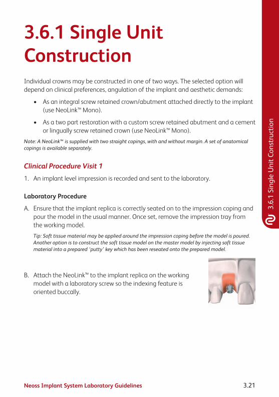
Neoss Implant System Laboratory Guidelines 3.21
3.6.
1 Si
ngle
Uni
t Con
stru
ctio
n
3.6.1 Single Unit ConstructionIndividual crowns may be constructed in one of two ways. The selected option will depend on clinical preferences, angulation of the implant and aesthetic demands:
• Asanintegralscrewretainedcrown/abutmentattacheddirectlytotheimplant(use NeoLink™ Mono).
• Asatwopartrestorationwithacustomscrewretainedabutmentandacementor lingually screw retained crown (use NeoLink™ Mono).
Note:ANeoLink™issuppliedwithtwostraightcopings,withandwithoutmargin.Asetofanatomicalcopings is available separately.
Clinical Procedure Visit 1
1. An implant level impression is recorded and sent to the laboratory.
Laboratory Procedure
A. Ensure that the implant replica is correctly seated on to the impression coping and pour the model in the usual manner. Once set, remove the impression tray from the working model.
Tip: Soft tissue material may be applied around the impression coping before the model is poured. Another option is to construct the soft tissue model on the master model by injecting soft tissue material into a prepared ‘putty’ key which has been reseated onto the prepared model.
B. Attach the NeoLink™ to the implant replica on the working model with a laboratory screw so the indexing feature is oriented buccally.

Neoss Implant System Laboratory Guidelines3.22
C. Assessing the location, proximity of adjacent teeth and occlusion, select the most appropriate preformed anatomical coping. If the Esthetiline Solution is applied,then the best result is achieved by choosing the same type of coping matching the used Tissue Former. The coping is mounted on the NeoLink™, rotated in to the preferred position, and then pushed firmly onto the NeoLink™ until it is properly seated (no gap).
Note:ThereisanindexingbetweenthecopingandtheMonoNeoLinks™(theplaneontheNeoLink™matchesaplaneinthecoping)inordertoachieve a specific orientation in relation to the implant’s rotational position. However, the copings can still be rotated freely for maximum flexibility by applying additional force.
D. The plastic coping can be modified to provide the optimal emergence profile, contour and occlusal form. This is carried out by selective grinding with a bur (tungsten carbide or diamond), or by addition using an appropriate dental wax or self polymerising pattern resin.
• Waxdesignforaseparatescrewretainedabutmentwithacement or lingual screw retained crown.
• Waxdesignforscrewretainedcrowndirecttoimplant.
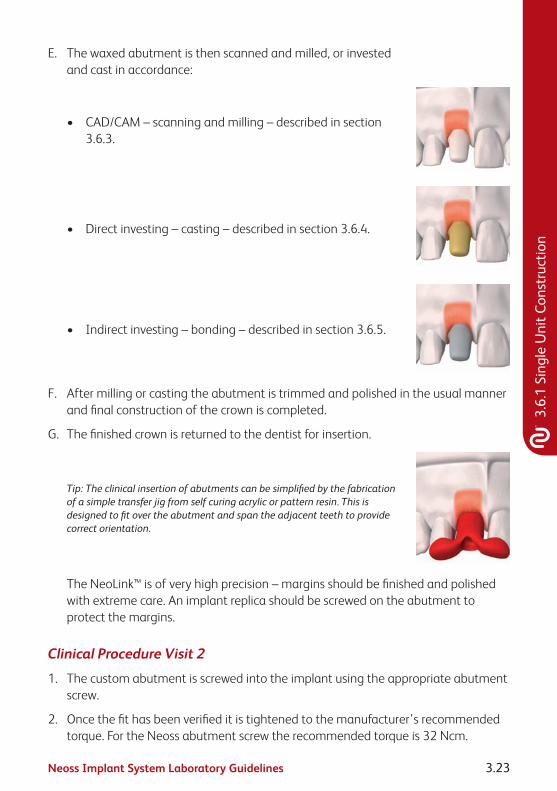
Neoss Implant System Laboratory Guidelines 3.23
3.6.
1 Si
ngle
Uni
t Con
stru
ctio
n
E. The waxed abutment is then scanned and milled, or invested and cast in accordance:
• CAD/CAM–scanningandmilling–describedinsection3.6.3.
• Directinvesting–casting–describedinsection3.6.4.
• Indirectinvesting–bonding–describedinsection3.6.5.
F. After milling or casting the abutment is trimmed and polished in the usual manner and final construction of the crown is completed.
G. The finished crown is returned to the dentist for insertion.
Tip: The clinical insertion of abutments can be simplified by the fabrication of a simple transfer jig from self curing acrylic or pattern resin. This is designed to fit over the abutment and span the adjacent teeth to provide correct orientation.
The NeoLink™ is of very high precision – margins should be finished and polished with extreme care. An implant replica should be screwed on the abutment to protect the margins.
Clinical Procedure Visit 2
1. The custom abutment is screwed into the implant using the appropriate abutment screw.
2. Once the fit has been verified it is tightened to the manufacturer’s recommended torque. For the Neoss abutment screw the recommended torque is 32 Ncm.

Neoss Implant System Laboratory Guidelines3.24
3. If the crown was constructed as a separate unit it is then cemented onto the abutment in the desired manner.
Note: When cementing or lingually screw retaining a crown onto an abutment the screw access hole should be blocked out with an appropriate material (e.g. gutta-percha) prior to cementation of the crown.
When screw retaining a crown direct to the implant the screw access hole should be filled with a small amount of removable material then overfilled with a permanent material (e.g. composite resin).
4. The occlusion and retention are checked and verified.

Neoss Implant System Laboratory Guidelines 3.25
3.6.
2 M
ultip
le U
nit C
onst
ruct
ion
3.6.2 Multiple Unit ConstructionMultiple Unit implant supported bridges may be constructed in one of three ways. The selected option will depend on clinical preferences, angulation of the implant/s and aesthetic demands:
• Asanintegralscrewretainedonepiecebridgeattacheddirectlytotheimplants(use NeoLink™ Multi).
• As a cement retained or lingually screw retained bridge over ‘individual’ custom abutments which have been screwed direct to the implants (use NeoLink™ Mono).
• AsascrewretainedbridgeattachedtoimplantsviaangulatedorstraightAccessabutments, described in section 3.10.
Note:ANeoLink™issuppliedwithtwostraightcopings,withandwithoutmargin.Asetofanatomicalcopings is available separately.
Clinical Procedure Visit 1
1. An implant level impression is recorded and sent to the laboratory.
Laboratory Procedure
A multiple unit prosthesis may be constructed in 2 ways:
Either:
1. Screw Retained direct to the implant:
The bridge or framework is constructed as one piece in either gold or titanium and screwed direct to the implant.
NeoLink™ Multi is used.

Neoss Implant System Laboratory Guidelines3.26
Or:
2. Cemented or Lingual Screw Retained to Abutment or Framework:
The construction can be for a cemented or lingually screw retained prosthesis onto screw retained abutment/s or framework.
NeoLink™ Mono is used.
IMPORTANTNOTE:TheNeoLink™Multiisusedwheneitherthebridgeorbridgeframeworkwillbeconnected direct to the implants. This abutment will allow for a divergence or convergence of up to 40° between implants for Neoss System.
A Burnout NeoLink™ Multi is also available. This NeoLink™ is made of a burnout plastic and is used when a cast fit will be acceptable and the bridge or framework will be screw retained direct to the implant.
A. Ensure the implant replicas are correctly seated on to the impression copings and pour the model in the usual manner. Once set remove the impression tray from the working model.
Tip: Soft tissue material may be applied around the impression coping before the model is poured. Another option is to construct the soft tissue model on the master model by injecting soft tissue material into a prepared ‘putty’ key which has been reseated onto the prepared model.
B. Attach the NeoLinks™ to the implant replicas on the working model with labora tory screws.
C. Assessing the location, proximity of adjacent teeth and occlusion, select the most appropriate preformed anatomical coping. If the Esthetiline Solution is applied,then the best result is achieved by choosing the same type of coping matching the used Tissue Former. The coping is mounted on the NeoLink™, rotated in to the preferred position, and then pushed firmly onto the NeoLink™ until it is properly seated (no gap).
Note:ThereisanindexingbetweenthecopingandtheMonoNeoLinks™(theplaneontheNeoLink™matchesaplaneinthecoping)inordertoachieveaspecificorientationinrelationtotheimplant’s rotational position. However, the copings can still be rotated freely for maximum flexibility by applying additional force.

Neoss Implant System Laboratory Guidelines 3.27
3.6.
2 M
ultip
le U
nit C
onst
ruct
ion
D. The plastic copings can be modified to provide the optimal emergence profile, contour and occlusal form. This is accomplished by selective grinding with a bur (tungsten carbide or diamond) or by addition using an appropriate dental wax or self polymerising pattern resin.
• Waxdesignforscrewretainedbridgedirecttoimplant.
• Waxdesignforaseparatescrewretainedabutmentwitha cement or lingual screw retained bridge.
E. The waxed abutment is then scanned and milled or waxed and cast following either:
• CAD/CAM–scanning–describedinsection3.6.3.
• Directinvesting–casting–describedinsection3.6.4.
• Indirectinvesting–bonding–describedinsection3.6.5.
F. After milling or casting the framework is trimmed and polished in the usual manner and final construction of the bridge is completed.
Note: If the design of the prosthesis is for a multiple unit framework then it may be returned to the dentist prior to completion for a ‘metal try-in’ – if desired.

Neoss Implant System Laboratory Guidelines3.28
Tip: The clinical insertion of abutments can be simplified by the fabrication of a simple transfer jig made from self curing acrylic or pattern resin. The jig should be designed to fit over the abutments and/or span the adjacent teeth to provide correct positioning. A jig is not required when the abutments are cast into a multiple unit framework.
The NeoLink™ is of very high precision – margins should be finished and polished with extreme care. An implant analog should be screwed on the abutment to protect the margins.
Clinical Procedure Visit 2
1. The abutments or framework are screwed into the patient’s mouth using the abutment screws.
2. Once the fit has been verified it is tightened to the manufacturer’s recommended torque. For the Neoss abutment screw the recommended torque is 32 Ncm.
3. If the bridge is constructed as a separate unit it is then cemented or lingually screwed onto the abutments/framework in the desired manner.
Note: When cementing or lingually screw retaining a bridge onto abutments the screw access holes should be blocked out with an appropriate material (e.g. gutta-percha) prior to cementation of the bridge.
When screw retaining a bridge direct to the implants the screw access holes should be filled with a small amount of removable material then overfilled with a permanent material (e.g. composite resin).
4. The occlusion and retention are checked and verified.

Neoss Implant System Laboratory Guidelines 3.29
3.6.
3 CA
D/C
AM S
olut
ions
3.6.3 CAD/CAM SolutionsFor CAD/CAM abutments/frameworks: scan the abutment/framework according to the specific CAD/CAM system requirements. It is possible to produce abutments/frameworks with most major CAD/CAM systems. For further information contact your local Neoss representative.
For CAD/CAM systems providing double scan features we recommend the following procedure to ensure that the screw access hole is correctly read and scanned by the scanner, and to ensure that it is pre-prepared into the abutment/frameworks:
1. After final waxing/preparation of the abutment/framework on the model, insert an extension from the NeoLink™ to the outer surface of the screw access hole in the pre-formed plastic coping. Round plastic tube/rod of 2.5mm diameter may be used (alternatively use the impression coping screw).
2. This extension tube is trimmed ‘level to’ (or minimally above) the screw access hole in the preformed plastic coping.
3. Spray with scanning powder/paint if recommended by the CAD/CAM provider.
4. Remove waxed abutment from the NeoLink™ – being careful to leave the extension tube in correct position.
5. Spray exposed extension tube and NeoLink™ with scanning powder/paint if recommended.
6. Scan the NeoLink™ with the extension tube as the FIRST scan in the scanner.
7. Place the waxed abutment onto the NeoLink™ and do the SECOND scan – following the specific CAD/CAM manufacturer’s manual for double scanning techniques. This process will create a thin shell of material (ceramic, metal) over the screw access hole, which is easily removed prior to sintering, or after sintering by careful grinding for a ceramic restoration.
8. When a milled and sintered coping has been created it is then cemented on the NeoLink™ by:
A. Sandblasting the NeoLink™ with aluminium oxide of 50–100 microns – do not sandblast fitting surface of NeoLink™, use replica to protect the fitting surface.
B. Apply a resin bonded cement to the NeoLink™ according to manufacturer’s instructions.

Neoss Implant System Laboratory Guidelines3.30
C. Bonding the milled coping onto the NeoLink™ with a preferred cement – according to the cement manufacturer’s recommendations. An opaque cement is optimal. Please refer to the cement recommended by the CAD/CAM provider.

Neoss Implant System Laboratory Guidelines 3.31
3.6.
4 D
irect
Inve
stin
g –
Cast
ing
3.6.4 Direct Investing – CastingThe prepared coping attached to the NeoLink™ is removed intact from the model by first removing the laboratory screw.
The NeoLink™ ‘remains’ in situ.
Note:GoldNeoLinks™arefabricatedfromanon-oxidisinggoldalloysuitable for direct casting.
The abutment/framework is then invested using an appro priate investment material and cast.
Tip:AsthegoldNeoLink™ismadeofnon-oxidisingalloy,ensurethedesignallowsfor0.2mmof‘new’alloy at the interface to avoid porcelain cracks.
Hint: During investing do not use solvent based wetting agents that can damage the surface of the plasticcopings.ItisalsorecommendedthatwettingagentsarenotappliedtothegoldNeoLink™.
The specific manufacturer’s guidelines in relation to investing, burnout times, temperatures, melting, and casting should be adhered too. Following casting and cooling the investment is gently removed with an ultrasonic cleaner, water jet or acid pickling NOT sandblasting.

Neoss Implant System Laboratory Guidelines3.32
3.6.5 Indirect Investing – Framework BondingIt is necessary to bond directly to the titanium NeoLink™, as it is not possible to cast a number of alloys and metals, including c.p. titanium.
The completed custom abutment or framework is removed from the model with the NeoLinks™ in situ. The NeoLinks™ are carefully removed from the prepared framework.
It is then invested in the appropriate investment and cast in conventional dental laboratory techniques for casting titanium or other conventional non-precious alloys.
Tip: During investing do not use solvent based wetting agents that can damage the surface of the plastic copings.
The specific manufacturer’s guidelines in relation to investing, burnout times, temperatures, melting and casting should be adhered to. When the abutment or framework has been cast the NeoLinks™ are relocated in the framework and reseated on the master model. Please refer to note below for details. There are a number of cements and bonding materials suitable for this technique. The manufacturer’s recommendations should be adhered to.
Note:InorderfortheNeoLink™tobeeasilyreseatedintothecastabutment/frameworksomeadjustments may be required:
Note: BONDING – to maintain maximum surface area it is recommended that careful/selective grinding bedoneinsidethecastabutment/framework.BEFOREcementingorbonding,theNeoLink™mustbeblasted with 50–150 micron particles in order for the cast abutment/framework to achieve appropriate retentiontotheNeoLink™.ITISIMPORTANTTOprotectthemarginsandtheseatingsurfaceoftheNeoLink™byattachinganimplantreplicatotheabutmentBEFOREBLASTING.
Note:LaserweldingoftheTiNeoLinks™isnotrecommendedsincethelowcollarheight,0.3mm,mightimpair the welding result.
Tip: To reduce the possibility of the framework discolouring, do not ‘steam clean’ the framework for at least 20 mins after polishing.
The NeoLink™ is of very high precision – margins should be finished and polished with extreme care. An implant replica should be screwed on the abutment to protect the margins.

Neoss Implant System Laboratory Guidelines 3.33
3.7
Tita
nium
Pre
pabl
e Ab
utm
ents
3.7 Titanium Prepable AbutmentsPrepable abutments may be placed directly into the patient’s mouth and prepared intra-orally or adjusted by the technician on a laboratory model. Care should be taken when preparing titanium intra-orally.
The Neoss System offers Titanium Prepable Abutments in various shapes ranging from incisors to molar, angulations (straight 0° and 15°) and heights (1mm, 1.5mm and 3mm) (1mm only for Ø3.25mm implant).
If the shape/contours of the desired abutment/s are not achievable with either of the Titanium Prepable Abutments then it is recommended to custom-design and cast the abutment in the laboratory utilising a Gold NeoLink™ Mono or Titanium NeoLink™ Mono – please refer to sections 3.6.1 “Single Unit Construction” and 3.6.2 “Multiple Unit Construction” of these guidelines.
Titanium Prepable Abutments – Preparation On Laboratory ModelClinical Procedure Visit 1
1. An implant level impression is recorded and sent to the laboratory.
Laboratory Procedure
A. Ensure that the implant replica is correctly attached to the impression coping. The working model is poured in the desired material.
Tip: Soft tissue material may be applied around the impression coping before the model is poured. Another option is to construct the soft tissue model on the master model by injecting soft tissue material into a preprepared ‘putty’ key which has been reseated onto the prepared model.
B. Appropriate Titanium Prepable Abutment is selected and screw retained to the implant replica in the working model with the laboratory screw provided. If the Esthetiline Solution is applied,then the best result is achieved by choosing the same type of Prepable Abutment matching the used Tissue former.

Neoss Implant System Laboratory Guidelines3.34
C. The necessary adjustments are made to the titanium abutment using either a tungsten carbide or diamond bur.
Tip: Ideally the margins of the abutment should be 1 to 1.5mm sub-gingival.
D. After the desired shape has been achieved either a temporary or permanent crown/bridge is produced in the material of choice using conventional dental laboratory procedures.
E. The prosthesis is returned to the dentist for insertion.
Tip: The clinical insertion of abutments can be simplified by the fabrication of a simple transfer jig from self curing acrylic or pattern resin. This is designed to fit over the abutment and span the adjacent teeth to provide correct orientation.
Clinical Procedure Visit 2
1. The abutment/s is screwed into the patient’s mouth using the Neoss abutment screw and screwdriver in conjunction with the manual handle.
2. Once the fit has been verified it is tightened to 32 Ncm.
3. The crown or bridge is then seated on the abutments and checked for fit, occlusion, colour etc.
4. The prosthesis is permanently cemented using conventional crown and bridge techniques.
5. The occlusion and retention are checked and verified.
Titanium Prepable Abutments – Preparation Intra-orallyClinical Procedure Visit 1
1. The healing or provisional abutment is removed and the top of the implant is exposed.
2. Appropriate Titanium Prepable Abutment is selected and screw retained to the implant/s or replica using the abutment screw provided. The use of screwdriver and manual handle is required.
Note: For optimal placement of the abutment and minimal preparation it is recommended the implant has been indexed as described in section 1.2.
Hint: If there are any concerns in relation to correct seating of the abutment to the implant than a radiograph should be taken.

Neoss Implant System Laboratory Guidelines 3.35
3.7
Tita
nium
Pre
pabl
e Ab
utm
ents
3. Adjustments to the abutment are made with high-speed grinding using either a tungsten or diamond bur with irrigation and high volume aspiration.
Tip: It is sometimes easier to mark the abutment where it needs adjusting whilst in the mouth, then remove and adjust.
Note: Ideally the margins of the abutment should be 1 to 1.5mm sub-gingival.
4. Once the ideal contour has been obtained and correct seating of the abutment to the implant has been verified the abutment screw is tightened to 32 Ncm.
5. The screw access hole is then blocked out (e.g. gutta-percha) and a conventional crown and bridge impression is taken. Gingival retraction cord may be used.
6. A temporary prosthesis is made and inserted.
7. The impression is sent to the laboratory for the construction of the prosthesis.
Laboratory Procedure
A. The impression is poured in the desired material to produce a conventional crown and bridge model.
B. The prosthesis is constructed utilising conventional crown and bridge laboratory techniques.
C. The completed prosthesis is returned to the dentist for insertion.
Clinical Procedure Visit 2
1. The temporary prosthesis is removed and the abutment cleaned of any debris.
2. The prosthesis is inserted and checked for fit, occlusion, colour etc.
3. The prosthesis is permanently cemented using conventional crown and bridge techniques.

Neoss Implant System Laboratory Guidelines3.36
3.8 Zirconia AbutmentZirconia abutments may be used for cement-retained single and multiple unit restorations and screw-retained single unit restorations and can be prepared at the chairside or by the technician on a laboratory model. Zirconia abutments are supplied in two parts; a Zirconia coping, having a range of profiles to match the Tissue Formers, and a pre-blasted Titanium NeoLink™ Mono. The Zirconia coping is designed to be cemented onto the NeoLink™.
Zirconia Abutment – Chairside (preparation and cementation extra-orally)Clinical Procedure Visit 1
1. The healing abutment is removed in order to expose the implant.
2. An appropriate Zirconia abutment is selected.
Note:Try-inusingNeoLink™andplasticcopings.IftheEsthetilineSolutionisapplied,thebestresultis achieved by choosing the coping matching the Tissue Former placed at surgery.
Preparation and cementation extra-orally
3. Screw retained the pre-blasted NeoLink™ to a replica/handle with the Laboratory Screw provided.
Note:IndextheflatplaneoftheNeoLink™inabuccaldirection.
Note:Try-intheZirconiacoping,ifnecessaryontheimplantbyscrewretainingthepre-blastedNeoLink™totheimplantwiththeAbutment Screw by hand tightening and mark any adjustments needed on the coping.
4. Modify the coping to achieve the optimal design as described below in section ‘Zirconia coping modification’.
5. After the ideal contour has been obtained, permanently cement the zirconia coping onto the Neolink by using conventional techniques.
Note:BecauseoftheprecisionfitbetweentheNeoLink™andtheZirconiacoping,onlyasmallcement gap is present (20–50μm). Apply a small amount of cement and ensure that any excess cement is removed. Check that the screw access channel is clear. Apply a resin bonded cement accordingtomanufacturer’sinstructionstotheNeoLink™.

Neoss Implant System Laboratory Guidelines 3.37
3.8
Zirc
onia
Abu
tmen
t
6. Remove the Zirconia abutment (NeoLink™ and Zirconia coping) from the replica/handle.
7. Attach the Zirconia abutment on the implant in the proper orientation and once correct seating of the abutment to the implant has been verified the abutment screw is tightened to 32 Ncm.
Note: If there are any concerns in relation to correct seating of the abutment on the implant than a radiograph should be taken.
Note:EnsurethattheZirconiaabutmentiscleananddry.
8. The screw access hole is then blocked out with a suitable material and a conventional crown and bridge impression is taken. Gingival retraction cord may be used.
9. A temporary prosthesis is made and attached to the Zirconia abutment.
10. The impression is sent to the laboratory for the construction of the crown which is sent to the clinician.
11. The crown (or full-ceramic restoration) must be conditioned and cemented according to the manufacturer’s instructions.
Zirconia Abutment – Preparation by LaboratoryClinical Procedure Visit 1
1. The healing abutment is removed in order to expose the implant and an implant level impression is taken and sent to the laboratory.
Note: For Esthetiline, the type of Tissue Former placed at surgery is communicated to lab.
Laboratory Procedure 1
A. The stone model is poured with a soft tissue mask around the replica.
B. Once the appropriate Zirconia abutment is selected, screw retain the pre-blasted NeoLink™ to a replica with the Laboratory Screw provided.
Note:Try-inusingNeoLink™andplasticcopings.IftheEsthetilineSolution is applied, the best result is achieved by choosing the coping matching the Tissue Former used at surgery. Mark any adjustments needed.
Note:IndextheflatplaneoftheNeoLink™inabuccualdirection.

Neoss Implant System Laboratory Guidelines3.38
C. Modify the coping to achieve the optimal design as described below in section ‘Zirconia coping modification’.
D. After the ideal contour has been obtained, permanently cement the zirconia coping onto the NeoLink™ by using conventional techniques.
Note:BecauseoftheprecisionfitbetweentheNeoLink™andtheZirconiacoping,onlyasmallcement gap is present (20–50μm). Apply a small amount of cement and ensure that any excess cement is removed. Check that the screw access channel is clear. Apply a resin bonded cement accordingtomanufacturer’sinstructionstotheNeoLink™.
E. A permanent crown is produced in the material of choice using conventional dental laboratory procedures. The Zirconia abutment (NeoLink™ and Zirconia coping) is removed from the replica/handle and returned, if applicable with the crown, to the dentist for final placement.
Clinical Procedure Visit 2
1. Attach the Zirconia abutment on the implant in the proper orientation. Once correct seating of the abutment to the implant has been verified the abutment screw is tightened to 32 Ncm.
Note: If there are any concerns in relation to correct seating of the abutment to the implant then a radiograph should be taken.
Note:EnsurethatZirconiaabutmentiscleananddry.
2. The screw access hole is then blocked out with a suitable material.
3. The crown (or full-ceramic restoration) must be conditioned and cemented/bonded according to the manufacturer’s instructions.
Zirconia coping modificationAdjust the coping outside the mouth by using burs especially manufactured for preparation of ceramics. Use water cooling to avoid micro cracks. Do not overheat the coping. Work with a low contact pressure.
Note: The replica can be attached to a handle for better stability during preparation.
Avoid sharp preparation edges and corners to ensure a good fit between the abutment and all-ceramic crown. Keep corners rounded with a radius of 0.5mm or more. Ensure that the minimal thickness of the ceramic material is 0.8mm and a height of 5mm from the implant platform. The maximum thickness of the veneering material on top

Neoss Implant System Laboratory Guidelines 3.39
3.8
Zirc
onia
Abu
tmen
t
of the coping must not exceed a maximum of 2.0mm in all directions. It is advised that the prosthetic margin be 0.5–1.0mm sub gingival – this will allow for easy removal of excess cement.
Note: Make sure not to damage the titanium implant interface during modification. Any adjustment below the final crown margin should be polished, preferably using a silicon rubber wheel and diamond paste.
Note:ItisrecommendedthatadjustmentoftheZirconiacopingismadepriortocementation!

Neoss Implant System Laboratory Guidelines3.40
3.9 Express AbutmentThe Express Abutment may be used to fabricate ‘cement retained’ crowns and partial bridges on Neoss System Implants in the maxilla and mandible. The Express Abutment is a pre-manufactured component and the fabrication process of the restoration is similar to that for conventional crowns and bridges. The impression is taken on abutment level. It is not recommended to use the Express Abutment when:
• millingand/orshorteningoftheabutmentisrequired.
• theabutmentshoulderwouldbemorethan1.5mmsub-gingival.
• theratioofcrownlengthtoimplantlengthexceeds1:1.25.
• onbridgeswithanabutmentdivergenceofmorethan8°.
• onØ3.25mmimplants.
Express Abutment
Express Healing Cap
Express Impression Cap
Express Replica
Express Burnout Coping non-engaging
Express Burnout Coping
engaging

Neoss Implant System Laboratory Guidelines 3.41
3.9
Expr
ess
Abut
men
t
The Neoss System offers Express Abutments in collar heights of 0.7mm, 1.5mm and 2.5mm. All kits include sterile:
• 1ExpressAbutment
• 1ExpressImpressionCap
• 2ExpressBurnoutCopings(1engagingand1non-engaging)
• 1ExpressHealingCap(PEEK)
• 1ExpressReplica
• 1NeossAbutmentScrew
The engaging Burnout Coping is used for single tooth constructions and the non-engaging for multiple tooth constructions.
Selection and InsertionThe Express Abutment is selected by the clinician in relation to the mucosal thickness. The abutment shoulder should not lie deeper than 1.5mm below the mucosa so that excess cement can be easily removed.
Depending on the specific requirements of individual cases, the Express Abutment may be placed at the time of initial surgery, at the time of second stage surgery or anytime thereafter. Factors which may influence when the Express Abutment is placed are bone quality/quantity, initial stability, occlusion and the patient’s willingness to comply with the procedures.
Clinical Procedure – Abutment Placement
1. The top of the implant is exposed. If second stage surgery has been performed then the Healing Abutment is removed.

Neoss Implant System Laboratory Guidelines3.42
2. The appropriate height abutment is selected and screw retained to the implant with the Abutment Screw provided.
The use of the screwdriver (and Manual Handle) is required. The screw is tightened to 32 Ncm.
Note: A follow-up x-ray is advisable to check the correct placement of the abutment.
3. Retighten the abutment screw after approximately five minutes using the same torque value of 32 Ncm.
4. At this time either an impression of the Express Abutment is taken or the Express Healing Cap is placed, see Impression Procedure on the next page.
The Express Healing Cap is simply pushed onto the Express Abutment and ‘clicks’ firmly into position.
For longer healing times it is recommended to cement the Express Healing Cap with temporary cement.
Note: The Express Abutment must not be modified or customised, since this will compromise the fit of the prefabricated components.

Neoss Implant System Laboratory Guidelines 3.43
3.9
Expr
ess
Abut
men
t
Impression ProcedureClinical Procedure
1. If applicable remove the Express Healing Cap to expose the Express Abutment.
Note: The Cap is easily removed by rotating it slightly before removal.
2. The Express Impression Cap (supplied) is pressed lightly onto the Express Abutment. A detectable locking feedback signals that it is in the final position.
3. The impression is now taken following a closed tray procedure. It is possible to inject around the Express Impression Cap if desired.
Note: It is recommended to use silicone or polyether impression material in a closed tray for the impression.
4. When the impression material has set, the impression is removed from the patient’s mouth.
Note: The Express Impression Cap remains ‘in-situ’ in the impression material.

Neoss Implant System Laboratory Guidelines3.44
5. The Express Healing Cap is now re-inserted on the Express Abutment.
The Express Healing Cap is simply pushed onto the Express Abutment and ‘clicks’ firmly into position.
For longer healing times it is recommended to cement the Express Healing Cap with temporary cement.
Note: The Express Replica (supplied) must be positioned in the Express Impression Cap before fabricating the master cast. A detectable locking ‘click’ signals the final position.
Laboratory Procedure
After verification that the Express Replica is correctly positioned in the Express Impression Cap, the model is poured in the desired material to produce a master cast.
Tip: Soft tissue material may be applied around the Impression Coping before the model is poured. A soft tissue model can also be constructed on the master model by injecting soft tissue material into a pre-prepared ‘putty’ key which has been re-seated onto the prepared model.
Temporary Restorations
Temporary restorations may be constructed on the Express Abutment in conventional manners (grind out a prefabricated plastic tooth).

Neoss Implant System Laboratory Guidelines 3.45
3.9
Expr
ess
Abut
men
t
Prosthetic RestorationAfter fabrication of the master cast, the final ‘cement’ retained prosthesis is constructed utilising the Express Burnout Copings.
Note: The Express Abutment must not be modified or customised, since this will compromise the fit of the prefabricated components.
The Express Burnout Coping which engages the Express Abutment is used for single tooth construction and the non-engaging Burnout Coping is used for multiple unit construction.
Laboratory Procedure
1. The appropriate Express Burnout Coping is used to construct either a single crown or a partial bridge.
2. The wax-up is made directly onto the Express Burnout Coping and the coping or framework is completed utilising conventional techniques in the material of choice.
Note: The elastic O-ring on the Express Replica holds the Burnout Copings in position. It is important to ensure that during the preparation the crown margin and abutment shoulder are flush together and no chamfer is created.

Neoss Implant System Laboratory Guidelines3.46
Note: Due to the precision fit of the Express Burnout Copings, no corrections of the crown margin are required after casting.
3. The prosthesis is returned to the dentist for insertion.
Clinical Procedure
1. The Express Healing Cap is removed from the patient.
Note: The Cap is easily removed by rotating it slightly before removal.
2. The prosthesis is now seated onto the Neoss Express Abutments and checked for fit, occlusion, colour etc.
3. The prosthesis is permanently cemented. Apply cement to the inner surface of the cervical margins before the crown is seated.
Note: Apply a resin bonded cement according to manufacturer’s instructions.
Note: Because of the precision fit between the Express Abutment and prosthesis only a small cement gap is available (20–50μm).
4. Carefully remove ALL excess cement or adhesive.
A full-ceramic restoration must be conditioned and cemented/bonded according to the manufacturer’s instructions.
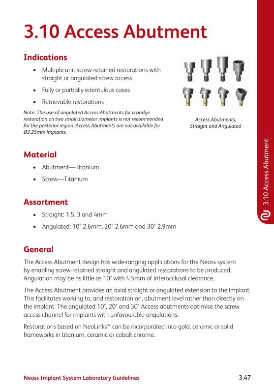
Neoss Implant System Laboratory Guidelines 3.47
3.10
Acc
ess
Abut
men
t
3.10 Access AbutmentIndications
• Multipleunitscrew-retainedrestorationswithstraight or angulated screw access
• Fullyorpartiallyedentulouscases
• Retrievablerestorations
Note: The use of angulated Access Abutments for a bridge restoration on two small diameter implants is not recommended for the posterior region. Access Abutments are not available for Ø3.25mm implants.
Access Abutments, Straight and Angulated
Material• Abutment—Titanium
• Screw—Titanium
Assortment• Straight:1.5,3and4mm
• Angulated:10°2.6mm,20°2.6mmand30°2.9mm
GeneralThe Access Abutment design has wide-ranging applications for the Neoss system by enabling screw-retained straight and angulated restorations to be produced. Angulation may be as little as 10° with 4.5mm of interocclusal clearance.
The Access Abutment provides an axial straight or angulated extension to the implant. This facilitates working to, and restoration on, abutment level rather than directly on the implant. The angulated 10°, 20° and 30° Access abutments optimise the screw access channel for implants with unfavourable angulations.
Restorations based on NeoLinks™ can be incorporated into gold, ceramic or solid frameworks in titanium, ceramic or cobalt chrome.

Neoss Implant System Laboratory Guidelines3.48
An abutment level impression is the procedure of choice to transfer the abutment location to the model.
Access Abutments are delivered sterile.
Access Abutment PlacementClinical Procedure
1. Select appropriate Access Abutment using Neoss Angulation Gauge.
2. Access Abutment, Angulated: The appropriate angulated abutment is placed on the implant and oriented in the correct position (six possible positions) using the pre-mounted abutment holder. Keep the pressure on the holder to avoid rotation of the abutment when tightening the screw. The abutment screw is then tightened using the Neoss screwdriver.
Access Abutment, Straight: The appropriate straight abutment is placed on the implant and screwed into position using the pre-mounted abutment holder.
Pre-mounted abutment holder Positioning and tightening of abutment
3. Final tightening of the abutment screw to 32 Ncm is carried out using the ratchet and Neoss screwdriver.
4. The disposable holder is removed from the abutment.
Note: The angulated abutment is preferably mounted at implant surgery or at second stage surgery for optimal tissue healing. Placement in already healed tissue might require additional soft tissue surgery for adequate seating of the angulated abutment. A radiograph can be taken to confirm accurate seating of the abutment.

Neoss Implant System Laboratory Guidelines 3.49
3.10
Acc
ess
Abut
men
t
Impression Procedure1. Position the Access Impression Coping (laser-
marked) onto the abutment and tighten the coping screw. The impression procedures, open or closed tray, are described in section 3.5 “Impression Techniques – Implant Level”. The impression is sent to the dental laboratory.
2. Place an Access Healing Abutment or a Temporary restoration, see sections 1.4 “Clinical Treatment” and 3.4 “Provisional Abutments”.
Placement of Healing Abutment
Laboratory Procedure
1. Access Abutment Replicas are secured in the copings located in the impression.
2. Pour a model including a soft tissue profile if possible.
3. Produce the restoration either by casting using gold NeoLinks™, as described in section 3.6 “NeoLink™ – the Concept” and 3.6.2 “Multiple Unit Construction”, or by using a milled framework in titanium or ceramic as described in section 3.6.3 “CAD/CAM Solutions”.
Final Restoration Placement
1. Remove the Access Healing Abutment or the temporary restoration from the abutment.
2. Connect the restoration to the abutment with prosthetic screws. Start with the central screw (if applicable) and tighten the remaining screws alternating between left and right sides.
3. Tighten the prosthetic screws to 20 Ncm using the ratchet and the screwdriver.
Placement of final restoration
4. Block out the screw access channel with gutta-percha. Use a suitable material such as light curing composite to fill in the screw access channel.

Neoss Implant System Laboratory Guidelines3.50
3.11 Overdenture SolutionsImplant supported overdentures are a relatively simple and cost-effective treatment option for many patients. In some cases it is not necessary to construct a new prosthesis as the patient’s existing denture may be utilised. Implant supported overdentures may also be used as a provisional prosthesis.
There are three ways to retain implant supported overdentures:
• Locator® Abutments
• BallAbutments
• BarAbutments
The use of ball abutments has traditionally been in the mandible utilising two implants.
Bar retained overdentures can either be rigid (multiple implants) or resilient (two implants) in design. Resilient designed overdentures are most commonly limited to the mandible and are implant retained and tissue borne. In the maxilla however bar retained overdentures are normally rigid in design and are implant retained and implant borne.
Locator® AbutmentsIndicationsThe Locator® Abutment is designed for use with full dentures or partial dentures retained by the Neoss Implants in the maxilla or mandible. The self-locating design allows a patient to easily seat their denture. Restorations with limited vertical space are possible through the 2.5mm total height of the Locator® Abutment attachment (abutment plus male). In addition, a 40° divergence between two implants can be easily accommodated.
Either a new denture or the patient’s existing denture can be utilised for the construction of a Locator® Abutment retained denture. Incorporating the male retentive element into the denture can be made in two ways:
• chairsidebythedentistdirectlyintopatient’sdentureinthemouth.
• inthelaboratoryonamodel.

Neoss Implant System Laboratory Guidelines 3.51
3.11
Ove
rden
ture
Sol
utio
ns
Contraindications
Not appropriate where a totally rigid connection is required.
Neoss Locator® abutments are not recommended for use on a single implant and on implants with a greater divergence than 40°.
Caution
Federal (USA) law restricts this device for sale by or on the order of a licensed dentist.
SterilisationAll components and instruments are supplied NON-STERILE. Implant abutments and metal instruments may be sterilised following standard clinical procedures, prior to use.
Procedure – New or Existing Denture1. The top of the implants are exposed by removing the Healing Abutments.
2. To select the proper Locator® Abutment measure the tissue thickness from the apical rim of the implant body to the crest of the gingiva at the highest side of the implant site. Choose the Locator® Abutment that exactly equals the tissue measurement, or is the next closest higher size available.
3. It is imperative that all bone and soft tissue is removed from the superior aspect of the implant body to guarantee complete seating of the Locator® Abutment. If any doubt, verify complete seating using a radiograph.

Neoss Implant System Laboratory Guidelines3.52
4. Hand-tighten the abutment into the implant, using the Neoss Locator® Driver Manual.
5. The abutment is then torqued to 32 Ncm using the ratchet.
Alternatively a torque control device with the Neoss Locator® Driver Machine can be used.
6. Place the Block out spacer over the Locator® Abutment (this will prevent acrylic resin from flowing into under-cuts around the housings).
Tip: A small piece of rubber dam may be placed over the Locator® Abutment prior to placing the Block out spacer to protect the soft tissue from the self curing material.

Neoss Implant System Laboratory Guidelines 3.53
3.11
Ove
rden
ture
Sol
utio
ns
7. Place the Locator® Male component (metal cap supplied with Black Processing Male in-situ) onto the Locator® Abutment leaving the Block out spacer beneath it.
8. Prepare a recess in the denture to accommodate the protruding Locator® Male. Try in the denture over the processing caps to verify it is fully seated on the ridge without contact onto the metal caps.
Note: Make sure there is NO contact between the denture and the metal processing cap.
9. Use a light cured composite resin or permanent self-curing acrylic to bond the processing cap to the denture. Apply a small amount in the recess of the denture and around the metal processing cap. Place the denture into position in the mouth and have the patient close into very light contact centric occlusion. Maintain the denture in a passive condition while the acrylic/resin sets as per the manufacturer’s instructions.
Note: It is critical that there is NO space between the tissue and the metal housing. It is necessary to block out any remaining undercuts to prevent resin/acrylic from locking the denture onto the abutment. This can be done by stacking additional Block out spacers.
10. After the resin/acrylic has cured remove the denture and discard the Block out spacers.
Fill any voids around the housings and polish.

Neoss Implant System Laboratory Guidelines3.54
11. Remove the Black Processing Male by placing the removal tip end of the Neoss Locator® Core Tool into the Black Processing Male assembly.
Then turn the handle three rotations counter clockwise.
12. Place the final Male attachment on the attachment insertion end of the Locator® Core Tool and press it firmly into the housing.
Note: The attachment retention on the abutment may be reduced by placing the Pink Light Retention Male or the Blue Extra Light Retention Male rather than the clear final male.
Note: The Male attachments are replaced after normal wear by inserting the removal tip end of the Neoss Locator® Core Tool into the Male assembly and turning the handle three rotations counter clockwise. Place the final Male attachment on the attachment insertion end of the Neoss Core Tool and press it firmly into the housing.
13. Upon insertion, check for pressure spots and adjust occlusion.

Neoss Implant System Laboratory Guidelines 3.55
3.11
Ove
rden
ture
Sol
utio
ns
Laboratory Procedure
A. After inserting the appropriate height Locator® Abutment onto the implants in the patient’s mouth, place the Locator® Impression Copings on the abutments and verify that it is correctly seated.
B. A medium or heavy body impression material is recommended. Syringe the impression material around each of the entire Locator® Impression Copings. Load the impression tray or patient’s existing denture and seat in the mouth. Allow the impression material to set per the manufacturer’s instructions.
C. Remove the impression from the mouth and verify that the impression material completely adapted around each coping. The Impression Copings should remain inside the impression.
D. Snap a Locator® Replica (2 supplied in each Impression Coping pack) onto each Impression Coping in the impression.
E. Pour the master cast, using high quality die stone.
F. The Black Processing Male must be securely positioned/fixed onto the replica. Proceed to processing/relining the denture.

Neoss Implant System Laboratory Guidelines3.56
G. Remove the Black Processing Male by placing the removal tip end of the Locator® Core Tool into the Black Processing Male assembly and turning the handle three rotations counter clockwise.
H. Place the final Male attachment on the attachment insertion end of the Core Tool and press it firmly into the housing.
Note: The attachment retention on the abutment may be reduced by placing the Pink Light Retention Male or the Blue Extra Light Retention Male rather than the clear final Male.
Note: The Male attachments are replaced after normal wear by inserting the removal tip end of the Neoss Locator® Core Tool into the Male assembly and turning the handle three rotations counter clockwise. Place the final Male attachment on the attachment insertion end of the Neoss Locator® Core Tool and press it firmly into the housing.
I. Upon insertion, check for pressure spots and adjust occlusion.
Choice of Neoss Locator® Replacement Males
Patients should be able to insert and remove their Locator® retained dentures simply and reliably.
To use the standard Locator® components the divergence for the Locator® Abutment must not exceed 10° (or 20° in the case of two abutments).

Neoss Implant System Laboratory Guidelines 3.57
3.11
Ove
rden
ture
Sol
utio
ns
Multiple Locator® AbutmentsIf several (3 or more) Locator® Abutments are used in the same jaw, we recommend using either:
• thePinkLocator® Replacement Male Light Retention with retention of 3.0 lbs or 1.36 kg.
Or:
• theBlueLocator® Replacement Male Extra Light Retention with retention of 1.5 lbs or 0.68 kg.
Converging or diverging Locator® AbutmentsIn the cases where implant divergences are between 10° to 20° (i.e. up to 40° in the case of two abutments), we recommend using either:
• theGreenLocator® Extended Range Male Normal Retention with retention of 4 lbs/1.36–1.82 kg.
Or:
• theRedLocator® Extended Range Male Extra Light Retention with retention of 1 lbs/0.68 kg.
Patient careGood oral hygiene is vital to implant success. The Locator® Abutment must be thoroughly cleaned daily. The use of a soft nylon bristle or end-tufted toothbrush, and super floss to polish the abutments should be taught.
A non-abrasive gel toothpaste, and an irrigation system is recommended to keep the socket of the Locator® Abutment clean.
Patients should maintain a three to four month recall for cleaning and implant evaluation.
The sulcus area around the implant abutment is the primary area of concern.
Use plastic instruments for scaling the abutments. Do not use metal instruments which may create scratches on the abutment surface. Examine patients for signs of inflammation around the implant abutments, and for implant mobility.
Use the gold plated abutment driver (Neoss Locator® Core Tool) to make sure the Locator® Abutment is tightened before the patient leaves the praxis.

Neoss Implant System Laboratory Guidelines3.58
Ball AbutmentsIn the mandible two implants are utilised and in the maxilla up to four implants are utilised for a ball retained overdenture.
Hint: For ball abutments to be a restorative option the implants must be parallel to within 10 degrees of each other.
Procedure – Ball Abutments Using Patient’s Existing DentureClinical Procedure Visit 1
1. The top of the implants are exposed by removing the healing abutments.
2. The appropriate height ball abutments are placed with the ball driver and tightened to 20 Ncm.
Tip: Ideally the collar of the ball abutment should extend approximately 1 to 1.5mm above the soft tissue.
3. The desired retentive element is selected and attached to the ball abutment/s. The denture should be well relieved in the area corresponding to the retentive element so as there is no contact between them and the denture. There should be an undercut well into which self curing resin will flow and be retained. The manufacturer’s recommended guidelines for processing and achieving the desired retentive force are followed.
4. A pick-up is carried out using a self curing acrylic or an appropriate attachment cement in the well in the denture. Once cured, the denture is lifted off together with the embedded retentive element of the ball abutment. The region of the denture around the attachment is then refined at the chairside or in the laboratory and care is taken to ensure the retentive element is not dislodged.
Hint: The retentive elements must be placed parallel to each other. A divergence or convergence of up to 10 degrees is acceptable.

Neoss Implant System Laboratory Guidelines 3.59
3.11
Ove
rden
ture
Sol
utio
ns
Procedure – Ball Abutments Constructing A New DentureClinical Procedure Visit 1
1. The top of the implants are exposed by removing the healing abutments.
2. A implant level impression is taken with Neoss impression copings. The impression should be a full arch impression in a custom made impression tray with either a polyvinyl or polyether impression material.
3. After the material has set the impression is removed from the patient’s mouth, the healing abutments are replaced and the provisional prosthesis is returned to the patient. Care should be taken that the provisional appliance does not interfere with the healing abutments. A soft lining material may be utilised in the provisional prosthesis to aid in retention.
Laboratory Procedure
A. Ensure that the implant replicas are correctly attached to the impression copings. The working model is poured in the conventional manner in the material of choice.
B. A screw retained ‘bite block’ or ‘occlusal registration rim’ is constructed by incorporating a provisional abutment PEEK or a healing abutment or an impression coping on at least two (2) implants.
Clinical Procedure Visit 2
1. The corresponding healing abutments are removed and the patient’s inter arch/jaw relationship is recorded onto the screw retained bite block/occlusal registration rim.
Hint: If not all of the healing abutments are removed it will be necessary to relieve the wax registration rim over the healing abutments which have not been utilised in the screw retention of this ‘bite block/occlusal registration rim’.
2. After registration the healing abutments are reseated in the patient’s mouth.
Laboratory Procedure
C. A full set up of the final prosthesis is constructed in wax.
Clinical Procedure Visit 3
1. The waxed prosthesis is evaluated in the patient’s mouth, once correct it is returned to the laboratory for processing.

Neoss Implant System Laboratory Guidelines3.60
Laboratory Procedure
D. The appropriate height ball abutments are placed on the working model with the ball driver.
Tip: Ideally the collar of the ball abutment should extend approximately 1 to 1.5mm above the soft tissue.
E. The desired retentive element is selected and the manufacturer’s recommended guidelines for processing and achieving the desired retentive force are followed.
F. The denture is then finished in the usual manner and the delivered to the dentist for insertion.
Note: The retentive elements must be placed parallel to each other. A divergence or convergence of up to 10 degrees is acceptable. It is also important that all undercuts below the retentive elements on the model are blocked out prior to processing.
Clinical Procedure Visit 4
1. The ball attachments are screwed into the implants after removal of the healing abutments and tightened to 20 Ncm.
2. The denture is returned to the patient and correctly seated.
3. The occlusion and retention are checked and verified.

Neoss Implant System Laboratory Guidelines 3.61
3.11
Ove
rden
ture
Sol
utio
ns
Bar AbutmentsA bar retained overdenture may be constructed utilising either:
• BarAbutment–Gold
• BarAbutment–Titanium
• BarAbutmentCoping–plastic.DesignedtobeusedinconjunctionwithaNeoLink™ this coping can be cast directly to or separate from the NeoLink™ depending on the NeoLink™ and alloy used. Please refer to section 3.6.4 “Direct Investing – Casting” or section 3.6.5 “Indirect Investing – Framework Bonding” of these guidelines for further information.
Procedure – Bar Abutment – Gold Using Patient’s Existing DentureClinical Procedure Visit 1
1. An implant level impression is recorded and sent to the laboratory.
Laboratory Procedure
A. After correctly attaching the implant replicas the model is constructed.
B. A Bar Abutment – Gold is attached to each implant with the laboratory screw provided.
C. Either a cast or pre-formed gold bar of the preferred design and contour is soldiered to the gold bar abutments in the desired position.
D. Once the fit has been verified, return the framework and the Neoss abutment screw (provided) to the dentist for insertion.
Clinical Procedure Visit 2
1. The framework is screwed into the patient’s mouth using the Neoss abutment screw and screwdriver in conjunction with the manual handle.
2. Once the fit has been verified it is tightened to 32 Ncm.
3. The denture is relieved so as it sits over the bar without any contact.
4. The bar is ‘blocked out’ and a conventional reline impression is taken.

Neoss Implant System Laboratory Guidelines3.62
Laboratory Procedure
E. The model is poured in a high-quality die stone – care should be taken when removing the denture from the model so as not to damage the bar impression.
F. The desired retentive element is selected and the manufacturer’s recommended guidelines for processing and achieving the desired retentive force are followed.
G. The denture is then finished in the usual manner and the delivered to the dentist for insertion.
Clinical Procedure Visit 3
1. The denture is delivered to the patient.
2. The occlusion and retention are checked and verified.
Procedure – Bar Abutment – Gold Constructing A New DentureClinical Procedure Visit 1
1. An implant level impression is recorded and sent to the laboratory.
Laboratory Procedure
A. After ensuring that the implant replicas are correctly attached to the impression coping the model is poured.
B. A screw retained ‘bite block’ or ‘occlusal registration rim’ is constructed by using healing or provisional abutments or impression coping on at least two implants.
Clinical Procedure Visit 2
1. The corresponding healing abutments are removed and the patient’s inter arch/jaw relationship is recorded onto the screw retained ‘bite block/occlusal registration rim’.
Hint: If not all the healing abutments are removed it will be necessary to relieve the wax registration rim over the healing abutments which have not been utilised in the screw retention of this ‘bite block/occlusal registration rim’.
2. After registration the healing abutments are returned to the patient’s mouth.
Laboratory Procedure
C. A full setup of the final prosthesis is constructed in wax.

Neoss Implant System Laboratory Guidelines 3.63
3.11
Ove
rden
ture
Sol
utio
ns
Clinical Procedure Visit 3
1. The waxed prosthesis is evaluated in the patient’s mouth, once correct it is returned to the laboratory for the bar construction.
Laboratory Procedure
D. A key covering the labial/buccal and occlusal surfaces is constructed.
E. The wax is eliminated and the teeth replaced into the key and repositioned onto the master model.
F. A Bar Abutment – Gold is attached to each implant with the laboratory screw provided.
G. Either a cast or pre-formed gold bar of the preferred design and contour is soldered or laser welded to the gold bar abutments in the desired position – ensure the framework doesn’t interfere with position of the teeth.
Tip: It may be desired at this stage to try the framework and/or the wax set-up in the patient’s mouth. If trying in the waxed set-up the key incorporating the teeth is repositioned onto the model, the bar is blocked out and wax flowed into the key to reproduce the required shape.
H. The desired retentive element is selected and the manufacturer’s recommended guidelines for processing and achieving the desired retentive force are followed.
I. The denture is then finished in the usual manner and the delivered to the dentist for insertion – the abutment screw provided with the Bar Abutment – Gold is also returned to the dentist.
Clinical Procedure Visit 4
1. The framework is screwed into the patient’s mouth using the Neoss abutment screw and screwdriver in conjunction with the manual handle.
2. Once the fit has been verified it is tightened to 32 Ncm.
3. The denture is delivered to the patient.
4. The occlusion and retention are checked and verified.

Neoss Implant System Laboratory Guidelines3.64
Procedure – Bar Abutment Coping – Plastic Using Patient’s Existing DentureClinical Procedure Visit 1
1. An implant level impression is recorded and sent to the laboratory.
Laboratory Procedure
A. After correctly attaching the implant replicas and pouring the model – either Gold NeoLink™ Multi, Plastic Burnout NeoLink™ Multi or Titanium NeoLink™ Multi are selected.
B. The NeoLinks™ are attached to the replicas in the model using the laboratory screw provided.
C. The Bar Abutment Copings – Plastic are firmly attached – ensure proper seating between the plastic coping and the NeoLink™.
D. Using either wax or a burnt out plastic the bar is constructed between the bar abutment copings to the appropriate contours.
E. The waxed framework is now sprued, invested and cast in the required alloy.
Tip: During investing do not use solvent based wetting agents that can damage the surface of the plastic copings.
Hint: Please refer to sections 3.6.4 or 3.6.5 of these guidelines for detailed instructions in relation to castingdirectlyorindirectlytoGoldorTitaniumNeoLinks™.TheNeoLink™PlasticBurnoutmustbeinvested and cast.
F. If the framework has been cast independently from the NeoLinks™ they should now be joined by either laser welding, soldering or resin bonding – please refer to section 3.6.5 “Indirect Investing – Framework Bonding” of these guidelines for more details.
Note:InorderfortheNeoLink™tobeeasilyreseatedintothecastabutment/frameworksomeadjustments may be required.
The NeoLink™ is of very high precision – margins should be finished and polished with extreme care. An implant replica should be screwed on the abutment to protect the margins.
G. Once the fit has been verified, return the cast framework to the dentist for insertion.

Neoss Implant System Laboratory Guidelines 3.65
3.11
Ove
rden
ture
Sol
utio
ns
Clinical Procedure Visit 2
1. The framework is screwed into the patient’s mouth using the Neoss abutment screw and screwdriver in conjunction with the manual handle.
2. Once the fit has been verified it is tightened to 32 Ncm.
3. The denture is relieved so as it sits over the bar without any contact.
4. The bar is ‘blocked out’ and a conventional reline impression is taken.
Laboratory Procedure
H. The model is poured in a high-quality die stone – care should be taken when removing the denture from the model so as not to damage the impressioned bar.
I. The desired retentive element is selected and the manufacturer’s recommended guidelines for processing and achieving the desired retentive force are followed.
J. The denture is then finished in the usual manner and the delivered to the dentist for insertion.
Clinical Procedure Visit 3
1. The denture is delivered to the patient.
2. The occlusion and retention are checked and verified.
Procedure – Bar Abutment Coping – Plastic Constructing A New DentureClinical Procedure Visit 1
1. An implant level impression is recorded and sent to the laboratory.
Laboratory Procedure
A. After ensuring that the implant replicas are correctly attached to the impression copings the model is poured.
B. A screw retained ‘bite block’ or ‘occlusal registration rim’ is constructed by using healing or provisional abutments or impression coping on at least two implants.

Neoss Implant System Laboratory Guidelines3.66
Clinical Procedure Visit 2
1. The corresponding healing abutments are removed and the patient’s inter arch/jaw relationship is recorded onto the screw retained ‘bite block/occlusal registration rim’.
Hint: If not all of the healing abutments are removed it will be necessary to relieve the wax registration rim over the healing abutments which have not been utilised in the screw retention of this ‘bite block/occlusal registration rim’.
2. After registration the healing abutments are returned to the patient’s mouth.
Laboratory Procedure
C. A full setup of the final prosthesis is constructed in wax.
Clinical Procedure Visit 3
1. The waxed prosthesis is evaluated in the patient’s mouth, once correct it is returned to the laboratory for the bar construction.
Laboratory Procedure
D. A key covering the labial/buccal and occlusal surfaces is constructed.
E. The wax is eliminated and the teeth replaced into the key and repositioned onto the master model.
F. Either Gold NeoLink™ Multi, Plastic Burnout NeoLink™ Multi or Titanium NeoLink™ Multi are selected.
G. The NeoLinks™ are attached to all of the implant replicas in the model using the laboratory screw provided.
H. The Bar Abutment Copings – Plastic are firmly attached – ensure proper seating between the plastic coping and the NeoLink™.
I. Using either wax or a burn-out plastic, the bar is constructed between the bar abutment copings to the appropriate contours.
J. Ensure the framework doesn’t interfere with the position of the teeth.
K. The waxed framework is now sprued, invested and cast in the required alloy.
Tip: During investing do not use solvent based wetting agents that can damage the surface of the plastic copings.
Hint: Please refer to sections 3.6.4 or 3.6.5 of these guidelines for detailed instructions in relation to castingdirectlyorindirectlytoGoldorTitaniumNeoLinks™.TheNeoLink™PlasticBurnoutmustbeinvested and cast.

Neoss Implant System Laboratory Guidelines 3.67
3.11
Ove
rden
ture
Sol
utio
ns
L. If the framework has been cast independently from the NeoLinks™ they should now be joined by either soldering or resin bonding – please refer to section 3.6.5 “Indirect Investing – Framework Bonding” of these guidelines for more details.
Note:InorderfortheNeoLink™tobeeasilyreseatedintothecastabutment/frameworksomeadjustments may be required.
The NeoLink™ is of very high precision – margins should be finished and polished with extreme care. An implant replica should be screwed on the abutment to protect the margins.
Hint: It may be desired at this stage to try the framework and/or the wax set-up in the patient’s mouth. If trying in the waxed set-up the key incorporating the teeth is repositioned onto the model, the bar is blocked out and wax flowed into the key to reproduce the required shape.
M. The desired retentive element is selected and the manufacturer’s recommended guidelines for processing and achieving the desired retentive force are followed.
N. The denture is then finished in the usual manner and the delivered to the dentist for insertion – the gold screw provided with the NeoLink™ is also returned to the dentist.
Clinical Procedure Visit 4
1. The framework is screwed into the patient’s mouth using the Neoss abutment screw and screwdriver in conjunction with the manual handle.
2. Once the fit has been verified it is tightened to 32 Ncm.
3. The denture is delivered to the patient.
4. The occlusion and retention are checked and verified.
Procedure Bar Abutment – Titanium Using Patient’s Existing DentureClinical Procedure Visit 1
1. An implant level impression is recorded and sent to the laboratory.
Laboratory Procedure
A. After correctly attaching the implant replicas the model is constructed.
B. A Bar Abutment – Titanium is attached to each implant with the laboratory screw provided.

Neoss Implant System Laboratory Guidelines3.68
C. Either a cast or pre-formed titanium bar of the preferred design and contour is laser welded to the titanium bar abutments in the desired position. Please refer to section “Laser Welding Titanium” below for further information.
D. Once the fit has been verified, return the framework and the Neoss abutment screw (provided) to the dentist for insertion.
Clinical Procedure Visit 2
1. The framework is screwed into the patient’s mouth using the Neoss abutment screw and screwdriver in conjunction with the manual handle.
2. Once the fit has been verified it is tightened to 32 Ncm.
3. The denture is relieved so as it sits over the bar without any contact.
4. The bar is ‘blocked out’ and a conventional reline impression is taken and sent to the laboratory for processing.
Laboratory Procedure
E. The model is poured in a high-quality die stone – care should be taken when removing the denture from the model so as not to damage the impressioned bar.
F. The desired retentive element is selected and the manufacturer’s recommended guidelines for processing and achieving the desired retentive force are followed.
G. The denture is then finished in the usual manner and the delivered to the dentist for insertion.
Clinical Procedure Visit 3
1. The denture is delivered to the patient.
2. The occlusion and retention are checked and verified.
Procedure Bar Abutment – Titanium Constructing A New DentureClinical Procedure Visit 1
1. An implant level impression is recorded and sent to the laboratory.
Laboratory Procedure
A. After ensuring that the implant replicas are correctly attached to the impression coping the model is poured.

Neoss Implant System Laboratory Guidelines 3.69
3.11
Ove
rden
ture
Sol
utio
ns
B. A screw retained ‘bite block’ or ‘occlusal registration rim’ is constructed by using healing or provisional abutments or impression coping on at least two implants.
Clinical Procedure Visit 2
1. The corresponding healing abutments are removed and the patient’s inter arch/jaw relationship is recorded onto the screw retained ‘bite block/occlusal registration rim’.
Hint: If not all of the healing abutments are removed it will be necessary to relieve the wax registration rim over the healing abutments which have not been utilised in the screw retention of this ‘bite block/occlusal registration rim’.
2. After registration the healing abutments are returned to the patient’s mouth.
Laboratory Procedure
C. A full setup of the final prosthesis is constructed in wax.
Clinical Procedure Visit 3
1. The waxed prosthesis is evaluated in the patient’s mouth, once correct it is returned to the laboratory for the bar construction.
Laboratory Procedure
D. A key covering the labial/buccal and occlusal surfaces is constructed.
E. The wax is eliminated and the teeth replaced into the key and repositioned onto the master model.
F. A Bar Abutment – Titanium is attached to each implant with the laboratory screw provided.
G. Either a cast or pre-formed titanium bar of the preferred design and contour is laser welded to the titanium bar abutments in the desired position – ensure the framework doesn’t interfere with position of the teeth. Please refer to section “Laser Welding Titanium” below for further information.
Tip: It may be desired at this stage to try the framework and/or the wax set-up in the patient’s mouth. If trying in the waxed set-up the key incorporating the teeth is repositioned onto the model, the bar is blocked out and wax flowed into the key to reproduce the required shape.
H. The desired retentive element is selected and the manufacturer’s recommended guidelines for processing and achieving the desired retentive force are followed.
I. The denture is then finished in the usual manner and the delivered to the dentist for insertion – the abutment screw provided with the Bar Abutment – Titanium is also returned to the dentist.

Neoss Implant System Laboratory Guidelines3.70
Clinical Procedure Visit 4
1. The framework is screwed into the patient’s mouth using the Neoss abutment screw and screwdriver in conjunction with the manual handle.
2. Once the fit has been verified it is tightened to 32 Ncm.
3. The denture is delivered to the patient.
4. The occlusion and retention are checked and verified.
Laser Welding TitaniumEnsure the Bar Abutments – Titanium are correctly seated onto the implant replicas and the titanium bar that is to be laser welded between them is correctly positioned/ assembled in the desired position on the working model.
It is recommended that the titanium bar be initially tacked in place with spot welds at 30–60° spacing around its periphery on the Bar Abutment – Titanium. The fit is then checked and then a double seam of overlapping welds is produced around each Bar Abutment – Titanium. The completed framework and welds can then be polished.
Tip: Do Not ‘Steam Clean’ the framework for at least 20 mins after polishing to reduce the possibility of the framework discolouring.
The Bar Abutment – Titanium is of very high precision – margins should be finished and polished with extreme care. An implant replica should be screwed on the abutment to protect the margins.

Neoss Implant System Laboratory Guidelines 3.71
3.12
Tec
hnic
al D
ata
3.12 Technical DataTitaniumAll Titanium Abutments and NeoLinks™ are made from Commercially Pure Titanium Grade 4–5 (alloy).
Physical Data Typical 4 Typical 5Melting Range °C±15°C (°F) 1668 (3034) 1668 (3034)
Thermal Exp. Coeff. (20–200°C) K–1 9.1 x 10⁻⁶ 8.6 x 10⁻⁶
Beta Transus °C±15°C(°F) 960 (1760) 980 (1796)
GoldAll NeoLinks™ for cast gold abutment or frameworks are fabricated from a non-oxidising high-fusing gold alloy and as such porcelain cannot be bonded directly to it. When casting onto the NeoLink/s™ ensure that the casting or bonding alloy is compatible. High gold content ISO 9693 (metal ceramic) NIOM Type A and ISO 1562 (dental gold casting alloy), Type 4 are suitable.
The melting range of the casting alloy must not distort or melt the NeoLink™ – less than 1250°C is recommended. Casting alloys should exhibit a proof stress of Rp0.2>500N/mm2 according to ISO 1562.
Composition Au 60%, Pt 24%, Pd 15%, Ir 1%
Colour White
Melting Range 1400–1460°C (2552–2660°F)
Hardness HV5 200±20
CTE500°C 12.5 µm/m.K
600°C 12.6 µm/m.K

Neoss Implant System Laboratory Guidelines3.72
3.13 Notes

Neoss Implant System Laboratory Guidelines 3.73
3.13
Not
es

Neoss Implant System Laboratory Guidelines3.74
Disclaimer of LiabilityNeoss products may only be used according to the manufacturers’ instructions and recommendations.
The user of Neoss products should determine their suitability for particular patients and indications.
Neoss Limited disclaims any liability, expressed or implied, and shall have no responsibility for any direct, indirect, punitive or other damages arising out of or in connection with any errors in professional judgement or practice in the use or placement of the Neoss products.
Caution: Federal (USA) law restricts this device to sale by or on the order of a licensed dentist or physician.
The Neoss Implant System has not been evaluated for safety and compatibility in the Magnetic Resonance environment. The Neoss Implant System has not been tested for heating or migration in the Magnetic Resonance environment.
Copyrights, design rights and trademarks.
Neoss documents, software and designs may not be reprinted, copied or published in whole or part, without the written authorisation of Neoss Limited.
ISO 13485:2003 MD 75473
0086
The Neoss implant assortment has FDA clearance for immediate placement and function recognizing sufficient bone stability and appropriate occlusal loading to restore chewing function.
Document #10501 12-03

Restorative Guidelines


Neoss Implant System Restorative Guidelines 4.1
Cont
ents
Contents
Restorative Guidelines4.1 Neoss Implant System 4.2
4.2 Esthetiline Solution 4.3
4.3 Provisional Abutments 4.8
4.4 Impression Techniques – Implant Level 4.11
4.5 NeoLink™ – the Concept 4.17
4.5.1 Single Unit Construction 4.19
4.5.2 Multiple Unit Construction 4.20
4.5.3 CAD/CAM Solutions 4.21
4.6 Titanium Prepable Abutments 4.23
4.7 Zirconia Abutment 4.25
4.8 Express Abutment 4.28
4.9 Access Abutment 4.34
4.10 Overdenture Solutions 4.37
4.11 Notes 4.50

Neoss Implant System Restorative Guidelines4.2
4.1 Neoss Implant SystemThe Neoss Implant System is a logical and simplified approach suitable for all dental implant treatment protocols: Immediate or Early Loading, Immediate Placement and One or Two Stage placement. The Neoss Implant System is available in 5 diameters Ø3.5, Ø4.0, Ø4.5, Ø5.0 and Ø5.5 and in addition there is a narrow Neoss Ø3.25mm implant. The implants are available in lengths from 7–17mm with some deviations, please refer to product catalogue for detailed information about available implant types, diameters and lengths.
The Neoss implants are a universal design for all bone qualities. The implants have both Thread Cutting and Thread Forming as the geometry of the implants ‘forms’ the site in poorer bone qualities optimising compression. They are self tapping implants with the primary cutting face designed to cut a precise thread profile and a secondary cutting face to control compression in dense bone.
The Neoss Bimodal implant has an altered surface structure. It is an ‘Ultra Clean’ surface. The modified Bimodal surface is created through ‘blasting’ techniques which are non-detrimental to the material properties. The Neoss ProActive® and Neoss Tapered implants are commercially pure titanium implants with an altered surface. This surface has been subjected to a multistage blasting, etching, cleaning and chemical treatment.
The Neoss implants have an internal connection. The implant is ‘picked up’ from a sterile glass vial with an Implant Inserter. The surgical drills are for single use and delivered in sterile condition for immediate use. There is only one screwdriver connection in the assortment and this is used for all components including cover screws, healing abutment screws, and final abutment screws.
All Neoss implants, except Ø3.25, have a single abutment connection as there is a single platform for all standard implant diameters. The abutment connection has zero rotation preventing abutment loosening and external wall deformation.
Neoss implants are provided in kits which include a cover screw, two healing abutments (only 5mm with Ø3.25mm implant) and a healing abutment screw. This complete delivery method enables the clinician to undertake either one or two stage surgery at time of placement without the need to have pre-ordered individual components.
The following information is a guide as requirements may vary on an individual basis.

Neoss Implant System Restorative Guidelines 4.3
4.2
Esth
etili
ne S
olut
ion
4.2 Esthetiline SolutionThe Esthetiline solution enables simple, rapid and effective anatomical tissue contouring to be developed and optimised with matching chair-side and laboratory restorative components. The Neoss Esthetiline solution provides seamless restorative integration all the way from implant placement to final crown restoration. The natural emergence profile developed during healing is matched perfectly in permanent restorative components; Prepable Titanium abutments, Zirconia abutments, custom abutments and copings, and CAD-CAM solutions as shown on next page.
The gingival margin abutment profile is fixed in relation to the non-rotational feature on all Esthetiline abutments and thus related to the position of the implant – indexing. The Esthetiline solution is best applied when the implant is oriented at surgery by ensuring that there is a groove in the buccual direction. This will require the least adjustment. Indexing throughout the treatment is possible utilising the indexing features as shown in the Esthetiline Overview on next page.

Neoss Implant System Restorative Guidelines4.4
Soft
Tiss
ue H
ealin
g
Tem
pora
ry S
olut
ions
Impr
essio
n So
lutio
ns
Esth
etic
Res
tora
tion
Esth
etili
ne O
verv
iew Prep
able
Ab
utm
ents
Not
Opt
imal
Opt
imal
Zirc
onia
Abut
men
tsN
eoLi
nk™
Pl
astic
Cop
ings
Set
Neo
Link
™ M
ono
Scre
w R
etai
ned
Cem
ent R
etai
ned/
Cha
irsid
e
Prod
uct A
ssor
tmen
tTr
eatm
ent O
ptio
nsIn
dexi
ng
Tiss
ue Fo
rmer
s
Tiss
ue Fo
rmer
s
Wid
eIn
sicor
Ø3.
5Ø
4.0
Ø4.
5Ø
5.0
Ø5.
5
Nar
row
Insic
orCa
nine
Pre-
mol
arM
olar
9x5x
12x
+

Neoss Implant System Restorative Guidelines 4.5
4.2
Esth
etili
ne S
olut
ion
Esthetiline Shapes
Narrow InsicorWide Insicor
31300 NeoLink™ Plastic Copings Set
Prepable Abutments
Zirconia Abutments
Tissue Formers
Canine Pre-molar Molar
31274
31294
31288
31273
31293
31287
31272
31292
312863128231280
#1 #2 #3 #4 #5 #6 #7 #8 #9 #10 #11 #12
3128331281 31284 31285
31271
31291
31270
31290
Note:PlasticcopingscanbeusedwithaNeoLink™astry-inabutmentstofacilitateabutmentselection.Plastic copings are for single use.

Neoss Implant System Restorative Guidelines4.6
Tissue Former – Healing & Provisional Abutment
Placement of Tissue Formers at implant placement or abutment connection guides the soft tissue and enables simple creation of the optimal emergence profile. Tissue formers are non-rotational and made in a range of anatomical shapes which are designed to match the profiles of individual incisor, canine, pre-molar and molar teeth.
Note: The trans-gingival section on Tissue Formers is slightly smaller buccally than matching restorative components in order to provide additional soft tissue volume.
Note: The Tissue Former – Molar can be rotated 90° if preferred but the implant has to be oriented accordingly at the time of surgery.
The Tissue Former may be adjusted as a healing abutment or prepared for a provisional crown or bridge. The PEEK/polymer structure makes it highly biocompatible whilst retaining ease of preparation, strength and ability to bond to crown and bridge resins. For more information about the use of Tissue Formers as healing and provisional abutment please refer to sections 1.4 ‘Clinical Treatment’ and 3.4 ‘Provisional Abutments’.
Impression TechniquesAfter the gingiva has been sculptured with the Tissue Former there are a series of treatment options; an impression may be taken to enable laboratory fabrication of a custom abutment or gold or metal framework in a traditional manner. Prepable Titanium or Zirconia abutments may also be prepared in the laboratory environment. An alternative option is to place a suitable Titanium Prepable or Zirconia Abutment directly at the chair-side and take a conventional crown impression.
Note:ItmayprovenecessarytopreparethemarginsoftheTitaniumPrepableorZirconiaAbutments,formoreinformationpleaserefertosections3.7‘TitaniumPrepableAbutments’and3.8‘ZirconiaAbutment’.
The standard Neoss impression coping is suitable for implant level impressions. There will typically be a gap between the impression coping and the sculpted anatomical gingiva which has been created by the Tissue Former. In the majority of cases the degree of tissue collapse will be minimal during the impression procedure and a normal impression technique syringing material between the coping and gingival will give an accurate result. If there is concern about tissue collapse a second Tissue Former of the same type may be used together with an impression coping screw for the impression. For more information about impression taking procedure please refer to section 3.5 ‘Impression Techniques – Implant Level’.

Neoss Implant System Restorative Guidelines 4.7
4.2
Esth
etili
ne S
olut
ion
Prepable Titanium Abutment
The shape of Prepable Titanium abutments match the profile of the Tissue Formers making it possible to accurately define soft tissue contours without the need for complex impression procedures. The abutments may be modified by marginal adaptation and angulation. For more information about Prepable Titanium Abutments please refer to section 3.7 ‘Titanium Prepable Abutments’.
Zirconia Abutment
Zirconia abutments are supplied in two parts; the Zirconia coping, with a profile matching the provisional Tissue Formers thus giving an optimal aesthetic solution, and a pre-blasted Titanium NeoLink™ Mono. The Zirconia coping is designed to be cemented onto the NeoLink™. This may be carried out at the chair-side or in laboratory using resin bonded cement. Careful adjustment of the ceramic coping may be made prior to cementation and placement. For more information about use of the Zirconia abutment please refer to section 3.8 ‘Zirconia Abutment’.
NeoLink™ Mono and NeoLink™ Plastic Copings
Individual crowns may be constructed utilising the NeoLink™ concept. The set of preformed plastic anatomical copings provide a complete range of abutment designs for different teeth, emergence profiles, heights and angulations. For best result choose the same type of coping matching the used Tissue Former. The different copings represent and correspond to the matching Tissue Formers as shown previously; copings #1–4 Wide Incisor, #5–8 Narrow Incisor, #9–10 Canine, #11 Pre-molar and #12 Molar.
Note:PlasticcopingscanbeusedwithaNeoLink™astry-inabutmentstofacilitateabutmentselection.Plastic copings are for single use.
There is an index between the NeoLink™ and the coping in order to achieve a specific orientation in relation to the implant’s rotational position.
For more information about custom abutments and copings and CAD/CAM solutions please refer to section 3.6 ‘NeoLink™ – the Concept’.

Neoss Implant System Restorative Guidelines4.8
4.3 Provisional AbutmentsTissue FormersThe Tissue Former may be used for cement or screw retained provisional restorations. The abutments may be placed directly into the patient’s mouth and prepared intra-orally or adjusted by the technician on a laboratory model. If the Esthetiline Solution is utilised, then the optimal result is achieved by choosing the same type of permanent restoration and same position as during healing.
Screw retained
1. Cut mechanical retention grooves or slots into the Tissue Former.
2. Construct a provisional crown/bridge in conventional manner. Ensure the screw access channel remains clear. Unscrew and remove the provisional abutment and contour margins/polish etc as required.
3. Insert the completed provisional crown/bridge and tighten to 10 Ncm.

Neoss Implant System Restorative Guidelines 4.9
4.3
Prov
isio
nal A
butm
ents
Cement retained
1. Insert the Tissue Former and tighten to 10 Ncm.
Note: no additional retention is required
2. Construct a provisional crown/bridge in conventional manner. Ensure the resin does not bond to the Tissue Former by for example using a separating medium.
3. It is important to remove and replace the provisional crown/bridge at least once prior to final setting of the restorative material to avoid difficulty in removing the crown/bridge once the restorative material has set.
4. Contour margins/polish etc as required.
5. Cement provisional crown/bridge onto Tissue Former with preferred temporary cement. Care should be taken to ensure that all excess cement is completely removed.
The provisionals are left in place for desired period, maximum 30 days.
Provisional Titanium AbutmentsProvisional Titanium Abutments are designed with a 0.7mm collar and are available both for single unit (Mono) and multiple unit (Multi) situations. The abutments may be prepared intra-orally, extra-orally or adjusted by the technician on a laboratory model. Care should be taken when preparing titanium intra-orally.
The component may also be used for as a waxing sleeve when constructing a crown/framework that will be scanned to produce CAD/CAM prosthesis or copy milled prosthesis.
Note: When using the Titanium Provisional Abutment as a waxing sleeve it is recommended to use a self curing resin direct to the abutment.
Note: cement retention is only recommended if the retention rings are blocked out.
Note: For protection and extension of the screw access hole use Laboratory Screw – Long.
Screw retained
Screw retained provisional crowns/bridges may be produced directly in the patients mouth or in the in the dental laboratory.
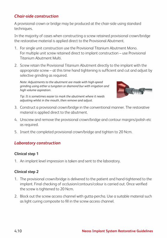
Neoss Implant System Restorative Guidelines4.10
Chair-side construction
A provisional crown or bridge may be produced at the chair-side using standard techniques.
In the majority of cases when constructing a screw retained provisional crown/bridge the restorative material is applied direct to the Provisional Abutment.
1. For single unit construction use the Provisional Titanium Abutment Mono. For multiple unit screw retained direct to implant construction – use Provisional Titanium Abutment Multi.
2. Screw retain the Provisional Titanium Abutment directly to the implant with the appropriate screw – at this time hand tightening is sufficient and cut and adjust by selective grinding as required.
Note: Adjustments to the abutment are made with high-speed grinding using either a tungsten or diamond bur with irrigation and high volume aspiration.
Tip: It is sometimes easier to mark the abutment where it needs adjusting whilst in the mouth, then remove and adjust.
3. Construct a provisional crown/bridge in the conventional manner. The restorative material is applied direct to the abutment.
4. Unscrew and remove the provisional crown/bridge and contour margins/polish etc as required.
5. Insert the completed provisional crown/bridge and tighten to 20 Ncm.
Laboratory construction
Clinical step 1
1. An implant level impression is taken and sent to the laboratory.
Clinical step 2
1. The provisional crown/bridge is delivered to the patient and hand-tightened to the implant. Final checking of occlusion/contours/colour is carried out. Once verified the screw is tightened to 20 Ncm.
2. Block out the screw access channel with gutta-percha. Use a suitable material such as light curing composite to fill in the screw access channel.

Neoss Implant System Restorative Guidelines 4.11
4.4
Impr
essi
on T
echn
ique
s –
Impl
ant L
evel
4.4 Impression Techniques – Implant LevelImplant level impressions may be used to accurately record implant positions easily using open or closed tray techniques for the Neoss System. Exceptions are the Express and Access Abutment which have their own specific copings. Impressions of Titanium Prepable Abutments can be taken using conventional crown and bridge method.
The purpose of an implant level impression is to accurately transfer to a laboratory model the position of the implant in relation to natural teeth or other implants as well as the soft tissue contours.
An Implant Level impression may be made at different stages during treatment and is dependant on operator preferences –
• Attimeofinitialsurgery–foronestagetechniques,ortoenablethedeliveryofa provisional crown at second stage surgery
• Atsecondstagesurgery
• Followingsofttissuehealingafterasecondstagesurgicalprocedure
The Neoss System offers one universal Implant Level Impression Coping for both ‘Open’ and ‘Closed’ Tray impression techniques as detailed below and one Impression Coping for ‘Open Tray’ impression only.
The universal impression coping is available in three different lengths – 8mm, 11mm and 18mm.
The universal Impression Coping utilises separate items depending on impression technique and is packaged with the implant replica.
Impression coping – which engages the implant has both horizontal and vertical grooves for definite retention in the impression material.
Screw – which secures the impression coping to the implant during impression taking (use screwdriver in conjunction with manual handle).

Neoss Implant System Restorative Guidelines4.12
Plastic extension tube– which may be trimmed to length and enables easy access to the head of the screw when using the ‘Open Tray’ technique.
Note: The impression copings are not interchangeable for reasons of accuracy. Hence use the same impression coping in the same impression cavity.
Red Plastic Cap – which is used for closed tray impressions only.
White Plastic Cap – used for auxiliary retention in open tray.
Impression Coping Open Tray.
Neoss Implant Level Impression TechniquesOpen Tray
In an open tray technique the impression coping is ‘picked up’ in the impression material. Only three of the four components of the universal Impression Coping Assembly are used, the Red and White Plastic Caps are NOT used.
Clinical Procedure – Open Tray
1. Use the universal Impression Coping as supplied.
Note: The Neoss Impression coping is ‘self-seating’. This means that the screw will not engage the implant if the coping is not correctly seated. However a radiograph is recommended if there is any uncertainty or risk of soft tissue entrapment.
2. Expose the head of the implant – e.g. remove the cover screw or healing/provisional abutment and ensure that the top of the implant is clear of any soft or hard tissue.
3. Place desired length impression coping (8, 11 or 18mm) (11mm for Ø3.25mm implant) Implant Level impression coping onto the implant and tighten the screw – hand tightening is sufficient, use the screwdriver and manual handle.

Neoss Implant System Restorative Guidelines 4.13
4.4
Impr
essi
on T
echn
ique
s –
Impl
ant L
evel
4. Try-in the modified impression tray (a window has been previously cut in the area of the implant) and ensure that the tray is clear of the impression coping and the plastic tube extends beyond the impression tray. The plastic tube may be reduced or removed prior to taking the impression. Place some wax over the window.
5. Using a medium to heavy body impression material, inject around the impression coping and fill the impression tray.
6. Seat the impression tray into the patient and ensure the plastic tube/s is clearly visible.
7. After the impression material has set, grasp the plastic sleeve with tweezers and remove.
8. Using the screwdriver ensure that the screw has been completely undone/disengaged from the coping and remove the impression.
Note: Upon removal of the impression the implants are covered by replacing the cover screw or healing/provisional abutment.
9. Using the screwdriver attach the implant replica to the impression coping. Whilst supporting the screw with the screwdriver, ensure correct seating and hand tighten – DO NOT OVER TIGHTEN (10 Ncm maximum).

Neoss Implant System Restorative Guidelines4.14
Note: The Impression Coping Open Tray utilises same procedure as above.
Impression Coping Cap Open Tray
The Impression Coping Cap Open Tray is used as an option to increase the retention of the impression coping during the open tray impressions.
The cap is aligned and firmly pushed onto the impression coping.
The impression coping is then used in the manner described above for the Neoss open tray impression technique.

Neoss Implant System Restorative Guidelines 4.15
4.4
Impr
essi
on T
echn
ique
s –
Impl
ant L
evel
Neoss Implant Level Impression TechniquesClosed Tray
In a closed tray technique the impression coping remains in the patient’s mouth when the impression is removed. Once the impression coping has been removed and the replica attached it is then re-seated into the impression. The Red Plastic Cap is utilised over the impression coping once it has been correctly seated into the patient’s mouth. The plastic extension tube is NOT used.
Note: This technique may be contraindicated in cases where implant angulation is severe.
Clinical Procedure – Closed Tray
1. Use the impression coping as supplied – however remove the plastic extension tube.
Note: The Neoss impression coping is ‘self-seating’. This means that the screw will not engage the implant if the coping is not correctly seated. However a radiograph is recommended if there is any uncertainty or risk of soft tissue entrapment.
2. Expose the implant – e.g. remove the cover screw or healing/provisional abutment and ensure that the top of the implant is clear of any soft or hard tissue.
3. Place the desired length impression coping (8, 11 or 18mm) (11mm for Ø3.25mm implant) Implant Level impression coping onto the implant and tighten the screw with the screwdriver and manual handle.
Position the Red Plastic Cap on the impression coping and firmly pushed until seated.
Note: The impression cap needs to be properly oriented on the impression coping, the 2 flat vertical sides help orientation so that the cap slides without resistance over the impression coping.
4. Using a medium to heavy body impression material, inject around the impression coping and fill the impression tray.
5. Seat the impression tray into the patient.

Neoss Implant System Restorative Guidelines4.16
6. When the impression material has set, remove the impression (the Red Plastic Impression Cap is ‘picked up’ in the impression).
7. Using the screwdriver unscrew and remove the Implant Level impression coping from the patient.
8. The implant replica (supplied with the impression coping) is now screwed into the impression coping.
9. Reposition the impression coping with replica attached back into the corresponding location in the Red Plastic Cap in the impression (use the two flat sides of the impression coping for alignment into the Red Plastic Cap).
The impression coping needs to be properly oriented in the Red Plastic Cap, meaning that the coping will slide without resistance almost completely down into the cap before a final push seats the coping.

Neoss Implant System Restorative Guidelines 4.17
4.5
Neo
Link
™ –
the
Conc
ept
4.5 NeoLink™ – the ConceptIntroductionThe Neoss Implant System abutments have been designed to facilitate the fabrication of custom designed screw retained gold, titanium and ceramic abutments or frameworks having a precision machined fit which are utilised in the production of cement or screw retained implant prosthesis.
Neoss abutments offer an efficient high accuracy prosthetic solution, whilst ensuring optimum quality control and offering an economical solution with numerous technical benefits.
Abutments and frameworks may be produced in zirconia or other options such as gold, titanium or cobalt chrome, or they may be CAD/CAM produced while maintaining the accuracy and tolerances obtained from machined components. This is possible due to the NeoLink™, which is a precision machined component made of gold, c.p. titanium or cobalt chrome, providing the interface between implant and abutment framework.
The set of preformed plastic anatomical copings, part of the Esthetiline Solution, provide a complete range of abutment designs for different teeth, emergence profiles, heights and angulations.
Once the accuracy of the Neoss replica has been checked on the master model, the choice is made to create a crown (NeoLink™ Mono) or bridge (NeoLink™ Multi) in gold, titanium or cobalt chrome. A custom abutment or framework is produced by combining the most appropriate design of plastic anatomical coping with the desired NeoLink™.
There are a number of options:
1. CAD/CAM abutments/frameworks cemented or bonded to the NeoLink/s™ titanium.
Note: Bonding of CAD/CAM designed copings or frameworks may be done ‘prior to’ or ‘after’ application of the porcelain/restorative material. This depends on the materials and techniques utilised.
2. Invest and cast directly onto the gold NeoLink™ with a suitable alloy.
3. Remove the NeoLink™ from the waxed coping/framework and cast the anatomical coping/framework (in a desired alloy) without the NeoLink™. After proper finishing of the cast coping/framework bond to the NeoLink/s™.
Note: The margin on the titanium abutments is too thin to be used in conjunction with welding a castcoping/frameworktotheNeoLink™.
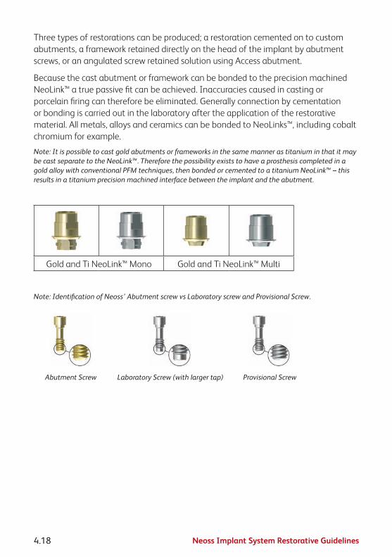
Neoss Implant System Restorative Guidelines4.18
Three types of restorations can be produced; a restoration cemented on to custom abutments, a framework retained directly on the head of the implant by abutment screws, or an angulated screw retained solution using Access abutment.
Because the cast abutment or framework can be bonded to the preci sion machined NeoLink™ a true passive fit can be achieved. Inaccuracies caused in casting or porcelain firing can therefore be eliminated. Generally connection by cementation or bonding is carried out in the laboratory after the application of the restorative material. All metals, alloys and ceramics can be bonded to NeoLinks™, including cobalt chromium for example.
Note: It is possible to cast gold abutments or frameworks in the same manner as titanium in that it may becastseparatetotheNeoLink™.ThereforethepossibilityexiststohaveaprosthesiscompletedinagoldalloywithconventionalPFMtechniques,thenbondedorcementedtoatitaniumNeoLink™–thisresults in a titanium precision machined interface between the implant and the abutment.
Gold and Ti NeoLink™ Mono Gold and Ti NeoLink™ Multi
Note: Identification of Neoss’ Abutment screw vs Laboratory screw and Provisional Screw.
Abutment Screw Laboratory Screw (with larger tap) Provisional Screw

Neoss Implant System Restorative Guidelines 4.19
4.5.
1 Si
ngle
Uni
t Con
stru
ctio
n
4.5.1 Single Unit ConstructionIndividual crowns may be constructed in one of two ways. The selected option will depend on clinical preferences, angulation of the implant and aesthetic demands:
• Asanintegralscrewretainedcrown/abutmentattacheddirectlytotheimplant(use NeoLink™ Mono).
• Asatwopartrestorationwithacustomscrewretainedabutmentandacementor lingually screw retained crown (use NeoLink™ Mono).
Note:ANeoLink™issuppliedwithtwostraightcopings,withandwithoutmargin.Asetofanatomicalcopings is available separately.
Clinical Procedure Visit 1
1. An implant level impression is recorded and sent to the laboratory.
Clinical Procedure Visit 2
1. The custom abutment is screwed into the implant using the appropriate abutment screw.
2. Once the fit has been verified it is tightened to the manufacturer’s recommended torque. For the Neoss abutment screw the recommended torque is 32 Ncm.
3. If the crown was constructed as a separate unit it is then cemented onto the abutment in the desired manner.
Note: When cementing or lingually screw retaining a crown onto an abutment the screw access hole should be blocked out with an appropriate material (e.g. gutta-percha) prior to cementation of the crown.
When screw retaining a crown direct to the implant the screw access hole should be filled with a small amount of removable material then overfilled with a permanent material (e.g. composite resin).
4. The occlusion and retention are checked and verified.

Neoss Implant System Restorative Guidelines4.20
4.5.2 Multiple Unit ConstructionMultiple Unit implant supported bridges may be constructed in one of three ways. The selected option will depend on clinical preferences, angulation of the implant/s and aesthetic demands:
• Asanintegralscrewretainedonepiecebridgeattacheddirectlytotheimplants(use NeoLink™ Multi).
• As a cement retained or lingually screw retained bridge over ‘individual’ custom abutments which have been screwed direct to the implants (use NeoLink™ Mono).
• AsascrewretainedbridgeattachedtoimplantsviaangulatedorstraightAccessabutments, described in section 3.10.
Note:ANeoLink™issuppliedwithtwostraightcopings,withandwithoutmargin.Asetofanatomicalcopings is available separately.
Clinical Procedure Visit 1
1. An implant level impression is recorded and sent to the laboratory.
Clinical Procedure Visit 2
1. The abutments or framework are screwed into the patient’s mouth using the abutment screws.
2. Once the fit has been verified it is tightened to the manufacturer’s recommended torque. For the Neoss abutment screw the recommended torque is 32 Ncm.
3. If the bridge is constructed as a separate unit it is then cemented or lingually screwed onto the abutments/framework in the desired manner.
Note: When cementing or lingually screw retaining a bridge onto abutments the screw access holes should be blocked out with an appropriate material (e.g. gutta-percha) prior to cementation of the bridge.
When screw retaining a bridge direct to the implants the screw access holes should be filled with a small amount of removable material then overfilled with a permanent material (e.g. composite resin).
4. The occlusion and retention are checked and verified.

Neoss Implant System Restorative Guidelines 4.21
4.5.
3 CA
D/C
AM S
olut
ions
4.5.3 CAD/CAM SolutionsFor CAD/CAM abutments/frameworks: scan the abutment/framework according to the specific CAD/CAM system requirements. It is possible to produce abutments/frameworks with most major CAD/CAM systems. For further information contact your local Neoss representative.
For CAD/CAM systems providing double scan features we recommend the following procedure to ensure that the screw access hole is correctly read and scanned by the scanner, and to ensure that it is pre-prepared into the abutment/frameworks:
1. After final waxing/preparation of the abutment/framework on the model, insert an extension from the NeoLink™ to the outer surface of the screw access hole in the pre-formed plastic coping. Round plastic tube/rod of 2.5mm diameter may be used (alternatively use the impression coping screw).
2. This extension tube is trimmed ‘level to’ (or minimally above) the screw access hole in the preformed plastic coping.
3. Spray with scanning powder/paint if recommended by the CAD/CAM provider.
4. Remove waxed abutment from the NeoLink™ – being careful to leave the extension tube in correct position.
5. Spray exposed extension tube and NeoLink™ with scanning powder/paint if recommended.
6. Scan the NeoLink™ with the extension tube as the FIRST scan in the scanner.
7. Place the waxed abutment onto the NeoLink™ and do the SECOND scan – following the specific CAD/CAM manufacturer’s manual for double scanning techniques. This process will create a thin shell of material (ceramic, metal) over the screw access hole, which is easily removed prior to sintering, or after sintering by careful grinding for a ceramic restoration.
8. When a milled and sintered coping has been created it is then cemented on the NeoLink™ by:
A. Sandblasting the NeoLink™ with aluminium oxide of 50–100 microns – do not sandblast fitting surface of NeoLink™, use replica to protect the fitting surface.
B. Apply a resin bonded cement to the NeoLink™ according to manufacturer’s instructions.

Neoss Implant System Restorative Guidelines4.22
C. Bonding the milled coping onto the NeoLink™ with a preferred cement – according to the cement manufacturer’s recommendations. An opaque cement is optimal. Please refer to the cement recommended by the CAD/CAM provider.

Neoss Implant System Restorative Guidelines 4.23
4.6
Tita
nium
Pre
pabl
e Ab
utm
ents
4.6 Titanium Prepable AbutmentsPrepable abutments may be placed directly into the patient’s mouth and prepared intra-orally or adjusted by the technician on a laboratory model. Care should be taken when preparing titanium intra-orally.
The Neoss System offers Titanium Prepable Abutments in various shapes ranging from incisors to molar, angulations (straight 0° and 15°) and heights (1mm, 1.5mm and 3mm) (1mm only for Ø3.25mm implant).
If the shape/contours of the desired abutment/s are not achievable with either of the Titanium Prepable Abutments then it is recommended to custom-design and cast the abutment in the laboratory utilising a Gold NeoLink™ Mono or Titanium NeoLink™ Mono – please refer to sections 3.6.1 “Single Unit Construction” and 3.6.2 “Multiple Unit Construction” of these guidelines.
Titanium Prepable Abutments – Preparation On Laboratory ModelClinical Procedure Visit 1
1. An implant level impression is recorded and sent to the laboratory.
Clinical Procedure Visit 2
1. The abutment/s is screwed into the patient’s mouth using the Neoss abutment screw and screwdriver in conjunction with the manual handle.
2. Once the fit has been verified it is tightened to 32 Ncm.
3. The crown or bridge is then seated on the abutments and checked for fit, occlusion, colour etc.
4. The prosthesis is permanently cemented using conventional crown and bridge techniques.
5. The occlusion and retention are checked and verified.

Neoss Implant System Restorative Guidelines4.24
Titanium Prepable Abutments – Preparation Intra-orallyClinical Procedure Visit 1
1. The healing or provisional abutment is removed and the top of the implant is exposed.
2. Appropriate Titanium Prepable Abutment is selected and screw retained to the implant/s or replica using the abutment screw provided. The use of screwdriver and manual handle is required.
Note: For optimal placement of the abutment and minimal preparation it is recommended the implant has been indexed as described in section 1.2.
Hint: If there are any concerns in relation to correct seating of the abutment to the implant than a radiograph should be taken.
3. Adjustments to the abutment are made with high-speed grinding using either a tungsten or diamond bur with irrigation and high volume aspiration.
Tip: It is sometimes easier to mark the abutment where it needs adjusting whilst in the mouth, then remove and adjust.
Note: Ideally the margins of the abutment should be 1 to 1.5mm sub-gingival.
4. Once the ideal contour has been obtained and correct seating of the abutment to the implant has been verified the abutment screw is tightened to 32 Ncm.
5. The screw access hole is then blocked out (e.g. gutta-percha) and a conventional crown and bridge impression is taken. Gingival retraction cord may be used.
6. A temporary prosthesis is made and inserted.
7. The impression is sent to the laboratory for the construction of the prosthesis.
Clinical Procedure Visit 2
1. The temporary prosthesis is removed and the abutment cleaned of any debris.
2. The prosthesis is inserted and checked for fit, occlusion, colour etc.
3. The prosthesis is permanently cemented using conventional crown and bridge techniques.

Neoss Implant System Restorative Guidelines 4.25
4.7
Zirc
onia
Abu
tmen
t
4.7 Zirconia AbutmentZirconia abutments may be used for cement-retained single and multiple unit restorations and screw-retained single unit restorations and can be prepared at the chairside or by the technician on a laboratory model. Zirconia abutments are supplied in two parts; a Zirconia coping, having a range of profiles to match the Tissue Formers, and a pre-blasted Titanium NeoLink™ Mono. The Zirconia coping is designed to be cemented onto the NeoLink™.
Zirconia Abutment – Chairside (preparation and cementation extra-orally)Clinical Procedure Visit 1
1. The healing abutment is removed in order to expose the implant.
2. An appropriate Zirconia abutment is selected.
Note:Try-inusingNeoLink™andplasticcopings.IftheEsthetilineSolutionisapplied,thebestresultis achieved by choosing the coping matching the Tissue Former placed at surgery.
Preparation and cementation extra-orally
3. Screw retained the pre-blasted NeoLink™ to a replica/handle with the Laboratory Screw provided.
Note:IndextheflatplaneoftheNeoLink™inabuccaldirection.
Note:Try-intheZirconiacoping,ifnecessaryontheimplantbyscrewretainingthepre-blastedNeoLink™totheimplantwiththeAbutment Screw by hand tightening and mark any adjustments needed on the coping.
4. Modify the coping to achieve the optimal design as described below in section ‘Zirconia coping modification’.
5. After the ideal contour has been obtained, permanently cement the zirconia coping onto the Neolink by using conventional techniques.
Note:BecauseoftheprecisionfitbetweentheNeoLink™andtheZirconiacoping,onlyasmallcement gap is present (20–50μm). Apply a small amount of cement and ensure that any excess cement is removed. Check that the screw access channel is clear. Apply a resin bonded cement accordingtomanufacturer’sinstructionstotheNeoLink™.
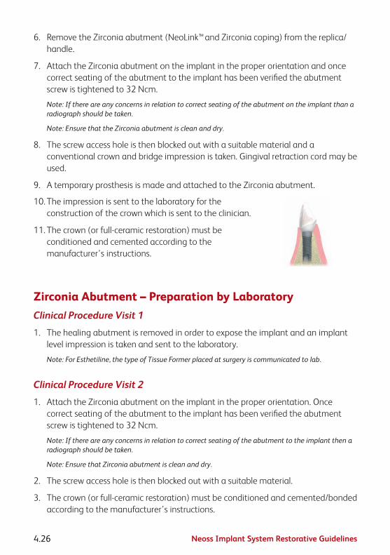
Neoss Implant System Restorative Guidelines4.26
6. Remove the Zirconia abutment (NeoLink™ and Zirconia coping) from the replica/handle.
7. Attach the Zirconia abutment on the implant in the proper orientation and once correct seating of the abutment to the implant has been verified the abutment screw is tightened to 32 Ncm.
Note: If there are any concerns in relation to correct seating of the abutment on the implant than a radiograph should be taken.
Note:EnsurethattheZirconiaabutmentiscleananddry.
8. The screw access hole is then blocked out with a suitable material and a conventional crown and bridge impression is taken. Gingival retraction cord may be used.
9. A temporary prosthesis is made and attached to the Zirconia abutment.
10. The impression is sent to the laboratory for the construction of the crown which is sent to the clinician.
11. The crown (or full-ceramic restoration) must be conditioned and cemented according to the manufacturer’s instructions.
Zirconia Abutment – Preparation by LaboratoryClinical Procedure Visit 1
1. The healing abutment is removed in order to expose the implant and an implant level impression is taken and sent to the laboratory.
Note: For Esthetiline, the type of Tissue Former placed at surgery is communicated to lab.
Clinical Procedure Visit 2
1. Attach the Zirconia abutment on the implant in the proper orientation. Once correct seating of the abutment to the implant has been verified the abutment screw is tightened to 32 Ncm.
Note: If there are any concerns in relation to correct seating of the abutment to the implant then a radiograph should be taken.
Note:EnsurethatZirconiaabutmentiscleananddry.
2. The screw access hole is then blocked out with a suitable material.
3. The crown (or full-ceramic restoration) must be conditioned and cemented/bonded according to the manufacturer’s instructions.

Neoss Implant System Restorative Guidelines 4.27
4.7
Zirc
onia
Abu
tmen
t
Zirconia coping modificationAdjust the coping outside the mouth by using burs especially manufactured for preparation of ceramics. Use water cooling to avoid micro cracks. Do not overheat the coping. Work with a low contact pressure.
Note: The replica can be attached to a handle for better stability during preparation.
Avoid sharp preparation edges and corners to ensure a good fit between the abutment and all-ceramic crown. Keep corners rounded with a radius of 0.5mm or more. Ensure that the minimal thickness of the ceramic material is 0.8mm and a height of 5mm from the implant platform. The maximum thickness of the veneering material on top of the coping must not exceed a maximum of 2.0mm in all directions. It is advised that the prosthetic margin be 0.5–1.0mm sub gingival – this will allow for easy removal of excess cement.
Note: Make sure not to damage the titanium implant interface during modification. Any adjustment below the final crown margin should be polished, preferably using a silicon rubber wheel and diamond paste.
Note:ItisrecommendedthatadjustmentoftheZirconiacopingismadepriortocementation!

Neoss Implant System Restorative Guidelines4.28
4.8 Express AbutmentThe Express Abutment may be used to fabricate ‘cement retained’ crowns and partial bridges on Neoss System Implants in the maxilla and mandible. The Express Abutment is a pre-manufactured component and the fabrication process of the restoration is similar to that for conventional crowns and bridges. The impression is taken on abutment level. It is not recommended to use the Express Abutment when:
• millingand/orshorteningoftheabutmentisrequired.
• theabutmentshoulderwouldbemorethan1.5mmsub-gingival.
• theratioofcrownlengthtoimplantlengthexceeds1:1.25.
• onbridgeswithanabutmentdivergenceofmorethan8°.
• onØ3.25mmimplants.
Express Abutment
Express Healing Cap
Express Impression Cap
Express Replica
Express Burnout Coping non-engaging
Express Burnout Coping
engaging

Neoss Implant System Restorative Guidelines 4.29
4.8
Expr
ess
Abut
men
t
The Neoss System offers Express Abutments in collar heights of 0.7mm, 1.5mm and 2.5mm. All kits include sterile:
• 1ExpressAbutment
• 1ExpressImpressionCap
• 2ExpressBurnoutCopings(1engagingand1non-engaging)
• 1ExpressHealingCap(PEEK)
• 1ExpressReplica
• 1NeossAbutmentScrew
The engaging Burnout Coping is used for single tooth constructions and the non-engaging for multiple tooth constructions.
Selection and InsertionThe Express Abutment is selected by the clinician in relation to the mucosal thickness. The abutment shoulder should not lie deeper than 1.5mm below the mucosa so that excess cement can be easily removed.
Depending on the specific requirements of individual cases, the Express Abutment may be placed at the time of initial surgery, at the time of second stage surgery or anytime thereafter. Factors which may influence when the Express Abutment is placed are bone quality/quantity, initial stability, occlusion and the patient’s willingness to comply with the procedures.
Clinical Procedure – Abutment Placement
1. The top of the implant is exposed. If second stage surgery has been performed then the Healing Abutment is removed.

Neoss Implant System Restorative Guidelines4.30
2. The appropriate height abutment is selected and screw retained to the implant with the Abutment Screw provided.
The use of the screwdriver (and Manual Handle) is required. The screw is tightened to 32 Ncm.
Note: A follow-up x-ray is advisable to check the correct placement of the abutment.
3. Retighten the abutment screw after approximately five minutes using the same torque value of 32 Ncm.
4. At this time either an impression of the Express Abutment is taken or the Express Healing Cap is placed, see Impression Procedure on the next page.
The Express Healing Cap is simply pushed onto the Express Abutment and ‘clicks’ firmly into position.
For longer healing times it is recommended to cement the Express Healing Cap with temporary cement.
Note: The Express Abutment must not be modified or customised, since this will compromise the fit of the prefabricated components.

Neoss Implant System Restorative Guidelines 4.31
4.8
Expr
ess
Abut
men
t
Impression ProcedureClinical Procedure
1. If applicable remove the Express Healing Cap to expose the Express Abutment.
Note: The Cap is easily removed by rotating it slightly before removal.
2. The Express Impression Cap (supplied) is pressed lightly onto the Express Abutment. A detectable locking feedback signals that it is in the final position.
3. The impression is now taken following a closed tray procedure. It is possible to inject around the Express Impression Cap if desired.
Note: It is recommended to use silicone or polyether impression material in a closed tray for the impression.
4. When the impression material has set, the impression is removed from the patient’s mouth.
Note: The Express Impression Cap remains ‘in-situ’ in the impression material.

Neoss Implant System Restorative Guidelines4.32
5. The Express Healing Cap is now re-inserted on the Express Abutment.
The Express Healing Cap is simply pushed onto the Express Abutment and ‘clicks’ firmly into position.
For longer healing times it is recommended to cement the Express Healing Cap with temporary cement.
Note: The Express Replica (supplied) must be positioned in the Express Impression Cap before fabricating the master cast. A detectable locking ‘click’ signals the final position.
Temporary Restorations
Temporary restorations may be constructed on the Express Abutment in conventional manners (grind out a prefabricated plastic tooth).

Neoss Implant System Restorative Guidelines 4.33
4.8
Expr
ess
Abut
men
t
Prosthetic RestorationAfter fabrication of the master cast, the final ‘cement’ retained prosthesis is constructed utilising the Express Burnout Copings.
Note: The Express Abutment must not be modified or customised, since this will compromise the fit of the prefabricated components.
The Express Burnout Coping which engages the Express Abutment is used for single tooth construction and the non-engaging Burnout Coping is used for multiple unit construction.
Clinical Procedure
1. The Express Healing Cap is removed from the patient.
Note: The Cap is easily removed by rotating it slightly before removal.
2. The prosthesis is now seated onto the Neoss Express Abutments and checked for fit, occlusion, colour etc.
3. The prosthesis is permanently cemented. Apply cement to the inner surface of the cervical margins before the crown is seated.
Note: Apply a resin bonded cement according to manufacturer’s instructions.
Note: Because of the precision fit between the Express Abutment and prosthesis only a small cement gap is available (20–50μm).
4. Carefully remove ALL excess cement or adhesive.
A full-ceramic restoration must be conditioned and cemented/bonded according to the manufacturer’s instructions.

Neoss Implant System Restorative Guidelines4.34
4.9 Access AbutmentIndications
• Multipleunitscrew-retainedrestorationswithstraight or angulated screw access
• Fullyorpartiallyedentulouscases
• Retrievablerestorations
Note: The use of angulated Access Abutments for a bridge restoration on two small diameter implants is not recommended for the posterior region. Access Abutments are not available for Ø3.25mm implants.
Access Abutments, Straight and Angulated
Material• Abutment—Titanium
• Screw—Titanium
Assortment• Straight:1.5,3and4mm
• Angulated:10°2.6mm,20°2.6mmand30°2.9mm
GeneralThe Access Abutment design has wide-ranging applications for the Neoss system by enabling screw-retained straight and angulated restorations to be produced. Angulation may be as little as 10° with 4.5mm of interocclusal clearance.
The Access Abutment provides an axial straight or angulated extension to the implant. This facilitates working to, and restoration on, abutment level rather than directly on the implant. The angulated 10°, 20° and 30° Access abutments optimise the screw access channel for implants with unfavourable angulations.
Restorations based on NeoLinks™ can be incorporated into gold, ceramic or solid frameworks in titanium, ceramic or cobalt chrome.

Neoss Implant System Restorative Guidelines 4.35
4.9
Acce
ss A
butm
ent
An abutment level impression is the procedure of choice to transfer the abutment location to the model.
Access Abutments are delivered sterile.
Access Abutment PlacementClinical Procedure
1. Select appropriate Access Abutment using Neoss Angulation Gauge.
2. Access Abutment, Angulated: The appropriate angulated abutment is placed on the implant and oriented in the correct position (six possible positions) using the pre-mounted abutment holder. Keep the pressure on the holder to avoid rotation of the abutment when tightening the screw. The abutment screw is then tightened using the Neoss screwdriver.
Access Abutment, Straight: The appropriate straight abutment is placed on the implant and screwed into position using the pre-mounted abutment holder.
Pre-mounted abutment holder Positioning and tightening of abutment
3. Final tightening of the abutment screw to 32 Ncm is carried out using the ratchet and Neoss screwdriver.
4. The disposable holder is removed from the abutment.
Note: The angulated abutment is preferably mounted at implant surgery or at second stage surgery for optimal tissue healing. Placement in already healed tissue might require additional soft tissue surgery for adequate seating of the angulated abutment. A radiograph can be taken to confirm accurate seating of the abutment.

Neoss Implant System Restorative Guidelines4.36
Impression Procedure1. Position the Access Impression Coping (laser-
marked) onto the abutment and tighten the coping screw. The impression procedures, open or closed tray, are described in section 3.5 “Impression Techniques – Implant Level”. The impression is sent to the dental laboratory.
2. Place an Access Healing Abutment or a Temporary restoration, see sections 1.4 “Clinical Treatment” and 3.4 “Provisional Abutments”.
Placement of Healing Abutment
Final Restoration Placement
1. Remove the Access Healing Abutment or the temporary restoration from the abutment.
2. Connect the restoration to the abutment with prosthetic screws. Start with the central screw (if applicable) and tighten the remaining screws alternating between left and right sides.
3. Tighten the prosthetic screws to 20 Ncm using the ratchet and the screwdriver.
Placement of final restoration
4. Block out the screw access channel with gutta-percha. Use a suitable material such as light curing composite to fill in the screw access channel.

Neoss Implant System Restorative Guidelines 4.37
4.10
Ove
rden
ture
Sol
utio
ns
4.10 Overdenture SolutionsImplant supported overdentures are a relatively simple and cost-effective treatment option for many patients. In some cases it is not necessary to construct a new prosthesis as the patient’s existing denture may be utilised. Implant supported overdentures may also be used as a provisional prosthesis.
There are three ways to retain implant supported overdentures:
• Locator® Abutments
• BallAbutments
• BarAbutments
The use of ball abutments has traditionally been in the mandible utilising two implants.
Bar retained overdentures can either be rigid (multiple implants) or resilient (two implants) in design. Resilient designed overdentures are most commonly limited to the mandible and are implant retained and tissue borne. In the maxilla however bar retained overdentures are normally rigid in design and are implant retained and implant borne.
Locator® AbutmentsIndicationsThe Locator® Abutment is designed for use with full dentures or partial dentures retained by the Neoss Implants in the maxilla or mandible. The self-locating design allows a patient to easily seat their denture. Restorations with limited vertical space are possible through the 2.5mm total height of the Locator® Abutment attachment (abutment plus male). In addition, a 40° divergence between two implants can be easily accommodated.
Either a new denture or the patient’s existing denture can be utilised for the construction of a Locator® Abutment retained denture. Incorporating the male retentive element into the denture can be made in two ways:
• chairsidebythedentistdirectlyintopatient’sdentureinthemouth.
• inthelaboratoryonamodel.

Neoss Implant System Restorative Guidelines4.38
Contraindications
Not appropriate where a totally rigid connection is required.
Neoss Locator® abutments are not recommended for use on a single implant and on implants with a greater divergence than 40°.
Caution
Federal (USA) law restricts this device for sale by or on the order of a licensed dentist.
SterilisationAll components and instruments are supplied NON-STERILE. Implant abutments and metal instruments may be sterilised following standard clinical procedures, prior to use.
Procedure – New or Existing Denture1. The top of the implants are exposed by removing the Healing Abutments.
2. To select the proper Locator® Abutment measure the tissue thickness from the apical rim of the implant body to the crest of the gingiva at the highest side of the implant site. Choose the Locator® Abutment that exactly equals the tissue measurement, or is the next closest higher size available.
3. It is imperative that all bone and soft tissue is removed from the superior aspect of the implant body to guarantee complete seating of the Locator® Abutment. If any doubt, verify complete seating using a radiograph.

Neoss Implant System Restorative Guidelines 4.39
4.10
Ove
rden
ture
Sol
utio
ns
4. Hand-tighten the abutment into the implant, using the Neoss Locator® Driver Manual.
5. The abutment is then torqued to 32 Ncm using the ratchet.
Alternatively a torque control device with the Neoss Locator® Driver Machine can be used.
6. Place the Block out spacer over the Locator® Abutment (this will prevent acrylic resin from flowing into under-cuts around the housings).
Tip: A small piece of rubber dam may be placed over the Locator® Abutment prior to placing the Block out spacer to protect the soft tissue from the self curing material.

Neoss Implant System Restorative Guidelines4.40
7. Place the Locator® Male component (metal cap supplied with Black Processing Male in-situ) onto the Locator® Abutment leaving the Block out spacer beneath it.
8. Prepare a recess in the denture to accommodate the protruding Locator® Male. Try in the denture over the processing caps to verify it is fully seated on the ridge without contact onto the metal caps.
Note: Make sure there is NO contact between the denture and the metal processing cap.
9. Use a light cured composite resin or permanent self-curing acrylic to bond the processing cap to the denture. Apply a small amount in the recess of the denture and around the metal processing cap. Place the denture into position in the mouth and have the patient close into very light contact centric occlusion. Maintain the denture in a passive condition while the acrylic/resin sets as per the manufacturer’s instructions.
Note: It is critical that there is NO space between the tissue and the metal housing. It is necessary to block out any remaining undercuts to prevent resin/acrylic from locking the denture onto the abutment. This can be done by stacking additional Block out spacers.
10. After the resin/acrylic has cured remove the denture and discard the Block out spacers.
Fill any voids around the housings and polish.

Neoss Implant System Restorative Guidelines 4.41
4.10
Ove
rden
ture
Sol
utio
ns
11. Remove the Black Processing Male by placing the removal tip end of the Neoss Locator® Core Tool into the Black Processing Male assembly.
Then turn the handle three rotations counter clockwise.
12. Place the final Male attachment on the attachment insertion end of the Locator® Core Tool and press it firmly into the housing.
Note: The attachment retention on the abutment may be reduced by placing the Pink Light Retention Male or the Blue Extra Light Retention Male rather than the clear final male.
Note: The Male attachments are replaced after normal wear by inserting the removal tip end of the Neoss Locator® Core Tool into the Male assembly and turning the handle three rotations counter clockwise. Place the final Male attachment on the attachment insertion end of the Neoss Core Tool and press it firmly into the housing.
13. Upon insertion, check for pressure spots and adjust occlusion.

Neoss Implant System Restorative Guidelines4.42
Choice of Neoss Locator® Replacement Males
Patients should be able to insert and remove their Locator® retained dentures simply and reliably.
To use the standard Locator® components the divergence for the Locator® Abutment must not exceed 10° (or 20° in the case of two abutments).
Multiple Locator® AbutmentsIf several (3 or more) Locator® Abutments are used in the same jaw, we recommend using either:
• thePinkLocator® Replacement Male Light Retention with retention of 3.0 lbs or 1.36 kg.
Or:
• theBlueLocator® Replacement Male Extra Light Retention with retention of 1.5 lbs or 0.68 kg.
Converging or diverging Locator® AbutmentsIn the cases where implant divergences are between 10° to 20° (i.e. up to 40° in the case of two abutments), we recommend using either:
• theGreenLocator® Extended Range Male Normal Retention with retention of 4 lbs/1.36–1.82 kg.
Or:
• theRedLocator® Extended Range Male Extra Light Retention with retention of 1 lbs/0.68 kg.

Neoss Implant System Restorative Guidelines 4.43
4.10
Ove
rden
ture
Sol
utio
ns
Patient careGood oral hygiene is vital to implant success. The Locator® Abutment must be thoroughly cleaned daily. The use of a soft nylon bristle or end-tufted toothbrush, and super floss to polish the abutments should be taught.
A non-abrasive gel toothpaste, and an irrigation system is recommended to keep the socket of the Locator® Abutment clean.
Patients should maintain a three to four month recall for cleaning and implant evaluation.
The sulcus area around the implant abutment is the primary area of concern.
Use plastic instruments for scaling the abutments. Do not use metal instruments which may create scratches on the abutment surface. Examine patients for signs of inflammation around the implant abutments, and for implant mobility.
Use the gold plated abutment driver (Neoss Locator® Core Tool) to make sure the Locator® Abutment is tightened before the patient leaves the praxis.
Ball AbutmentsIn the mandible two implants are utilised and in the maxilla up to four implants are utilised for a ball retained overdenture.
Hint: For ball abutments to be a restorative option the implants must be parallel to within 10 degrees of each other.
Procedure – Ball Abutments Using Patient’s Existing DentureClinical Procedure Visit 1
1. The top of the implants are exposed by removing the healing abutments.
2. The appropriate height ball abutments are placed with the ball driver and tightened to 20 Ncm.
Tip: Ideally the collar of the ball abutment should extend approximately 1 to 1.5mm above the soft tissue.
3. The desired retentive element is selected and attached to the ball abutment/s. The denture should be well relieved in the area corresponding to the retentive element so as there is no contact between them and the denture. There should be an undercut well into which self curing resin will flow and be retained. The

Neoss Implant System Restorative Guidelines4.44
manufacturer’s recommended guidelines for processing and achieving the desired retentive force are followed.
4. A pick-up is carried out using a self curing acrylic or an appropriate attachment cement in the well in the denture. Once cured, the denture is lifted off together with the embedded retentive element of the ball abutment. The region of the denture around the attachment is then refined at the chairside or in the laboratory and care is taken to ensure the retentive element is not dislodged.
Hint: The retentive elements must be placed parallel to each other. A divergence or convergence of up to 10 degrees is acceptable.
Procedure – Ball Abutments Constructing A New DentureClinical Procedure Visit 1
1. The top of the implants are exposed by removing the healing abutments.
2. A implant level impression is taken with Neoss impression copings. The impression should be a full arch impression in a custom made impression tray with either a polyvinyl or polyether impression material.
3. After the material has set the impression is removed from the patient’s mouth, the healing abutments are replaced and the provisional prosthesis is returned to the patient. Care should be taken that the provisional appliance does not interfere with the healing abutments. A soft lining material may be utilised in the provisional prosthesis to aid in retention.
Clinical Procedure Visit 2
1. The corresponding healing abutments are removed and the patient’s inter arch/jaw relationship is recorded onto the screw retained bite block/occlusal registration rim.
Hint: If not all of the healing abutments are removed it will be necessary to relieve the wax registration rim over the healing abutments which have not been utilised in the screw retention of this ‘bite block/occlusal registration rim’.
2. After registration the healing abutments are reseated in the patient’s mouth.
Clinical Procedure Visit 3
1. The waxed prosthesis is evaluated in the patient’s mouth, once correct it is returned to the laboratory for processing.

Neoss Implant System Restorative Guidelines 4.45
4.10
Ove
rden
ture
Sol
utio
ns
Clinical Procedure Visit 4
1. The ball attachments are screwed into the implants after removal of the healing abutments and tightened to 20 Ncm.
2. The denture is returned to the patient and correctly seated.
3. The occlusion and retention are checked and verified.
Bar AbutmentsA bar retained overdenture may be constructed utilising either:
• BarAbutment–Gold
• BarAbutment–Titanium
• BarAbutmentCoping–plastic.DesignedtobeusedinconjunctionwithaNeoLink™ this coping can be cast directly to or separate from the NeoLink™ depending on the NeoLink™ and alloy used. Please refer to section 3.6.4 “Direct Investing – Casting” or section 3.6.5 “Indirect Investing – Framework Bonding” of these guidelines for further information.
Procedure – Bar Abutment – Gold Using Patient’s Existing DentureClinical Procedure Visit 1
1. An implant level impression is recorded and sent to the laboratory.
Clinical Procedure Visit 2
1. The framework is screwed into the patient’s mouth using the Neoss abutment screw and screwdriver in conjunction with the manual handle.
2. Once the fit has been verified it is tightened to 32 Ncm.
3. The denture is relieved so as it sits over the bar without any contact.
4. The bar is ‘blocked out’ and a conventional reline impression is taken.
Clinical Procedure Visit 3
1. The denture is delivered to the patient.
2. The occlusion and retention are checked and verified.

Neoss Implant System Restorative Guidelines4.46
Procedure – Bar Abutment – Gold Constructing A New DentureClinical Procedure Visit 1
1. An implant level impression is recorded and sent to the laboratory.
Clinical Procedure Visit 2
1. The corresponding healing abutments are removed and the patient’s inter arch/jaw relationship is recorded onto the screw retained ‘bite block/occlusal registration rim’.
Hint: If not all the healing abutments are removed it will be necessary to relieve the wax registration rim over the healing abutments which have not been utilised in the screw retention of this ‘bite block/occlusal registration rim’.
2. After registration the healing abutments are returned to the patient’s mouth.
Clinical Procedure Visit 3
1. The waxed prosthesis is evaluated in the patient’s mouth, once correct it is returned to the laboratory for the bar construction.
Clinical Procedure Visit 4
1. The framework is screwed into the patient’s mouth using the Neoss abutment screw and screwdriver in conjunction with the manual handle.
2. Once the fit has been verified it is tightened to 32 Ncm.
3. The denture is delivered to the patient.
4. The occlusion and retention are checked and verified.

Neoss Implant System Restorative Guidelines 4.47
4.10
Ove
rden
ture
Sol
utio
ns
Procedure – Bar Abutment Coping – Plastic Using Patient’s Existing DentureClinical Procedure Visit 1
1. An implant level impression is recorded and sent to the laboratory.
Clinical Procedure Visit 2
1. The framework is screwed into the patient’s mouth using the Neoss abutment screw and screwdriver in conjunction with the manual handle.
2. Once the fit has been verified it is tightened to 32 Ncm.
3. The denture is relieved so as it sits over the bar without any contact.
4. The bar is ‘blocked out’ and a conventional reline impression is taken.
Clinical Procedure Visit 3
1. The denture is delivered to the patient.
2. The occlusion and retention are checked and verified.
Procedure – Bar Abutment Coping – Plastic Constructing A New DentureClinical Procedure Visit 1
1. An implant level impression is recorded and sent to the laboratory.
Clinical Procedure Visit 2
1. The corresponding healing abutments are removed and the patient’s inter arch/jaw relationship is recorded onto the screw retained ‘bite block/occlusal registration rim’.
Hint: If not all of the healing abutments are removed it will be necessary to relieve the wax registration rim over the healing abutments which have not been utilised in the screw retention of this ‘bite block/occlusal registration rim’.
2. After registration the healing abutments are returned to the patient’s mouth.
Neoss Implant System Restorative Guidelines4.48
Clinical Procedure Visit 3
1. The waxed prosthesis is evaluated in the patient’s mouth, once correct it is returned to the laboratory for the bar construction.
Clinical Procedure Visit 4
1. The framework is screwed into the patient’s mouth using the Neoss abutment screw and screwdriver in conjunction with the manual handle.
2. Once the fit has been verified it is tightened to 32 Ncm.
3. The denture is delivered to the patient.
4. The occlusion and retention are checked and verified.
Procedure Bar Abutment – Titanium Using Patient’s Existing DentureClinical Procedure Visit 1
1. An implant level impression is recorded and sent to the laboratory.
Clinical Procedure Visit 2
1. The framework is screwed into the patient’s mouth using the Neoss abutment screw and screwdriver in conjunction with the manual handle.
2. Once the fit has been verified it is tightened to 32 Ncm.
3. The denture is relieved so as it sits over the bar without any contact.
4. The bar is ‘blocked out’ and a conventional reline impression is taken and sent to the laboratory for processing.
Clinical Procedure Visit 3
1. The denture is delivered to the patient.
2. The occlusion and retention are checked and verified.

Neoss Implant System Restorative Guidelines 4.49
4.10
Ove
rden
ture
Sol
utio
ns
Procedure Bar Abutment – Titanium Constructing A New DentureClinical Procedure Visit 1
1. An implant level impression is recorded and sent to the laboratory.
Clinical Procedure Visit 2
1. The corresponding healing abutments are removed and the patient’s inter arch/jaw relationship is recorded onto the screw retained ‘bite block/occlusal registration rim’.
Hint: If not all of the healing abutments are removed it will be necessary to relieve the wax registration rim over the healing abutments which have not been utilised in the screw retention of this ‘bite block/occlusal registration rim’.
2. After registration the healing abutments are returned to the patient’s mouth.
Clinical Procedure Visit 3
1. The waxed prosthesis is evaluated in the patient’s mouth, once correct it is returned to the laboratory for the bar construction.
Clinical Procedure Visit 4
1. The framework is screwed into the patient’s mouth using the Neoss abutment screw and screwdriver in conjunction with the manual handle.
2. Once the fit has been verified it is tightened to 32 Ncm.
3. The denture is delivered to the patient.
4. The occlusion and retention are checked and verified.

Neoss Implant System Restorative Guidelines4.50
4.11 Notes

Neoss Implant System Restorative Guidelines 4.51
4.11
Not
es
Neoss Implant System Restorative Guidelines4.52
Disclaimer of LiabilityNeoss products may only be used according to the manufacturers’ instructions and recommendations.
The user of Neoss products should determine their suitability for particular patients and indications.
Neoss Limited disclaims any liability, expressed or implied, and shall have no responsibility for any direct, indirect, punitive or other damages arising out of or in connection with any errors in professional judgement or practice in the use or placement of the Neoss products.
Caution: Federal (USA) law restricts this device to sale by or on the order of a licensed dentist or physician.
The Neoss Implant System has not been evaluated for safety and compatibility in the Magnetic Resonance environment. The Neoss Implant System has not been tested for heating or migration in the Magnetic Resonance environment.
Copyrights, design rights and trademarks.
Neoss documents, software and designs may not be reprinted, copied or published in whole or part, without the written authorisation of Neoss Limited.
ISO 13485:2003 MD 75473
0086
The Neoss implant assortment has FDA clearance for immediate placement and function recognizing sufficient bone stability and appropriate occlusal loading to restore chewing function.
Document #10501 12-03

Neoss Implant System Guidelines 5.1
Torq
ue a
nd S
peed
Rec
omm
enda
tions
Neo
ss Im
plan
t Sys
tem
Tor
que
and
Spee
d Re
com
men
datio
ns
Impl
ants
Scre
w
Taps
Hea
ling
Prov
isio
nal
Impr
essi
onFi
nal r
esto
ratio
n
Cove
r Sc
rew
Hea
ling
Abut
men
t PE
EK a
nd
Tiss
ue
Form
er
Hea
ling
Abut
men
t Ti
Tiss
ue
Form
erPr
ovis
iona
lTi
Abu
tmen
tIm
pres
sion
Sc
rew
Abut
men
t Sc
rew
Ac
cess
Ab
utm
ent
Stra
ight
&
Angu
late
d
Acce
ss
Pros
thet
ic
Scre
w
Ball
Abut
men
tLo
cato
r®
Abut
men
t
45 M
ax40
-45
10 M
ax10
Max
10 M
ax10
2010
Max
3232
2020
32
Neo
ss Im
plan
t Sys
tem
Tor
que
Reco
mm
enda
tion
(Ncm
)
Dril
lsSc
rew
Tap
sCo
unte
rsin
ksIm
plan
tsBo
ne M
ill
800-
2000
*20
800
20 M
ax40
Max
Neo
ss Im
plan
t Sys
tem
Dril
ling/
Inse
rtio
n Sp
eed
Reco
mm
enda
tion
(rpm
)
* low
er s
peed
for l
arge
r dril
ls

Neoss Implant System Restorative Guidelines5.2

Inde
x
IndexSection
Surgical Guidelines 1
Assistant Guidelines 2
Laboratory Guidelines 3
Restorative Guidelines 4
Torque and Speed Recommendations 5
Page
3.10 Access Abutment (Laboratory) 3.47
4.9 Access Abutment (Restorative) 4.34
2.1 Assistant Guidelines 2.2
3.6.3 CAD/CAM Solutions (Laboratory) 3.29
4.5.3 CAD/CAM Solutions (Restorative) 4.21
2.7 Cleaning, Disinfection, Sterilisation and Storage 2.17
1.3 Clinical Assessment 1.11
1.4 Clinical Treatment 1.14
3.6.4 Direct Investing – Casting 3.31
2.5 Drilling Guides 2.10
3.3 Esthetiline Solution (Laboratory) 3.4
4.2 Esthetiline Solution (Restorative) 4.3
3.9 Express Abutment (Laboratory) 3.40
4.8 Express Abutment (Restorative) 4.28
1.1 General Features 1.2
3.5 Impression Techniques – Implant Level (Laboratory) 3.13
4.4 Impression Techniques – Implant Level (Restorative) 4.11
3.6.5 Indirect Investing – Framework Bonding 3.32
1.2 Instrumentation and Component Assortment 1.4

3.6.2 Multiple Unit Construction (Laboratory) 3.25
4.5.2 Multiple Unit Construction (Restorative) 4.20
3.6 NeoLink™ – the Concept (Laboratory) 3.19
4.5 NeoLink™ – the Concept (Restorative) 4.17
3.1 Neoss Implant System (Laboratory) 3.2
4.1 Neoss Implant System (Restorative) 4.2
2.8 Oral Hygiene and Patient Care 2.20
3.11 Overdenture Solutions (Laboratory) 3.50
4.10 Overdenture Solutions (Restorative) 4.37
2.9 Packaging Symbols 2.21
1.5 Post Operative Care 1.23
3.4 Provisional Abutments (Laboratory) 3.9
4.3 Provisional Abutments (Restorative) 4.8
3.2 Restorative Assistants 3.3
3.6.1 Single Unit Construction (Laboratory) 3.21
4.5.1 Single Unit Construction (Restorative) 4.19
2.3 Surgery Set-up 2.5
2.6 Surgical Drills 2.12
2.4 Surgical Procedure 2.9
3.12 Technical Data 3.71
3.7 Titanium Prepable Abutments (Laboratory) 3.33
4.6 Titanium Prepable Abutments (Restorative) 4.23
2.2 Treatment Options 2.4
3.8 Zirconia Abutment (Laboratory) 3.36
4.7 Zirconia Abutment (Restorative) 4.25


10501-6 UK 12-03 Printed in the UK © Neoss Limited, 2012. Copyrights, design rights and trademarks in this document are Neoss documents, software and designs, if it is not stated to the contrary. These may not be
reprinted, copied, or published in whole or in part, without the written authorisation of Neoss Limited.
AustraliaNeoss Australia Pty. LtdPO Box 404New FarmQLD 4005T +61 7 3216 0165F +61 7 3216 0135E [email protected]
AustriaNeoss GmbHT +49 221 55405-322F +49 221 55405-522E [email protected]
CroatiaMedical Intertrade d.o.o10431 Sveta NedeljaHRVATSKAT +385 1 33 74 020F +385 1 33 36 035E [email protected]
DenmarkNeoss ABMölnlycke Fabriker 3S-43535 MölnlyckeT + 46 31 88 12 80F + 46 31 88 12 89E [email protected]
GermanyNeoss GmbHIm MediaPark 8D-50670 KölnT +49 221 55405-322F +49 221 55405-522E [email protected]
ItalyNeoss Italia S.r.l.Via Marco Antonio Colonna, 42I-20149 MilanoT +39 02.92952.1 (centralino)F +39 02.92952.250E [email protected]
New ZealandNeoss Australia Pty. LtdT +61 7 3216 0165F +61 7 3216 0135E [email protected]
NorwayNeoss ABMölnlycke Fabriker 3S-43535 MölnlyckeT + 46 31 88 12 80F + 46 31 88 12 89E [email protected]
PolandTop Implant Technologies Sp. z o.o.ul. Owocowa 5Nowa Iwiczna05-500PiasecznoT +48 (22)7111110E [email protected]
Republic of IrelandPromedTulligmoreKillorglinCounty KerryT + 353 87 9980323F + 353 66 9761584E [email protected]
SwedenNeoss ABMölnlycke Fabriker 3S-43535 MölnlyckeT + 46 31 88 12 80F + 46 31 88 12 89E [email protected]
SwitzerlandFlexident AGSchützenmatte B 11Postfach 453Stansstad 6362T +41413104020F +41413104025E [email protected]
ThailandACTEON (Thailand) Ltd.23/45 Sorachai Building, 16th FloorSukhumvit 63 Road, Klongton NuaWattana, Bangkok 10110T +662-714-3295F +662-714-3296E [email protected]
TurkeyPlasma Health Services Industry and Trade CorporationKehribar Sakak No. 14 /7-8 06700GaziosmanpasaAnkaraT +90 (312) 4428270-5F +90 (312) 4428277E [email protected]
United KingdomNeoss LtdWindsor HouseCornwall RoadHarrogateHG1 2PWT +44 1423 817-733F +44 1423 817-744E [email protected]
United StatesNeoss Inc.21860 Burbank Blvd., Ste. 190Woodland HillsCA 91367Toll free 866 626-3677T +1 818 432-2600F +1 818 432-2640E [email protected]
www.neoss.com