Embed Size (px)
Citation preview
1
TABLE OF CONTENTS
Overview 3
Specifications 6
Cockpit Layout 7
Main Panel 8
Center Console Switchboard 11
Radios and AFCS 12
Overhead section 13
Procedures 14
Flight Manual
NEMETH DESIGNS DEVELOPMENT GROUP
SIKORSKY S-76A SPIRIT (FSX/FSXSE/P3D)
www.nemethdesigns.com
2
Overview
History
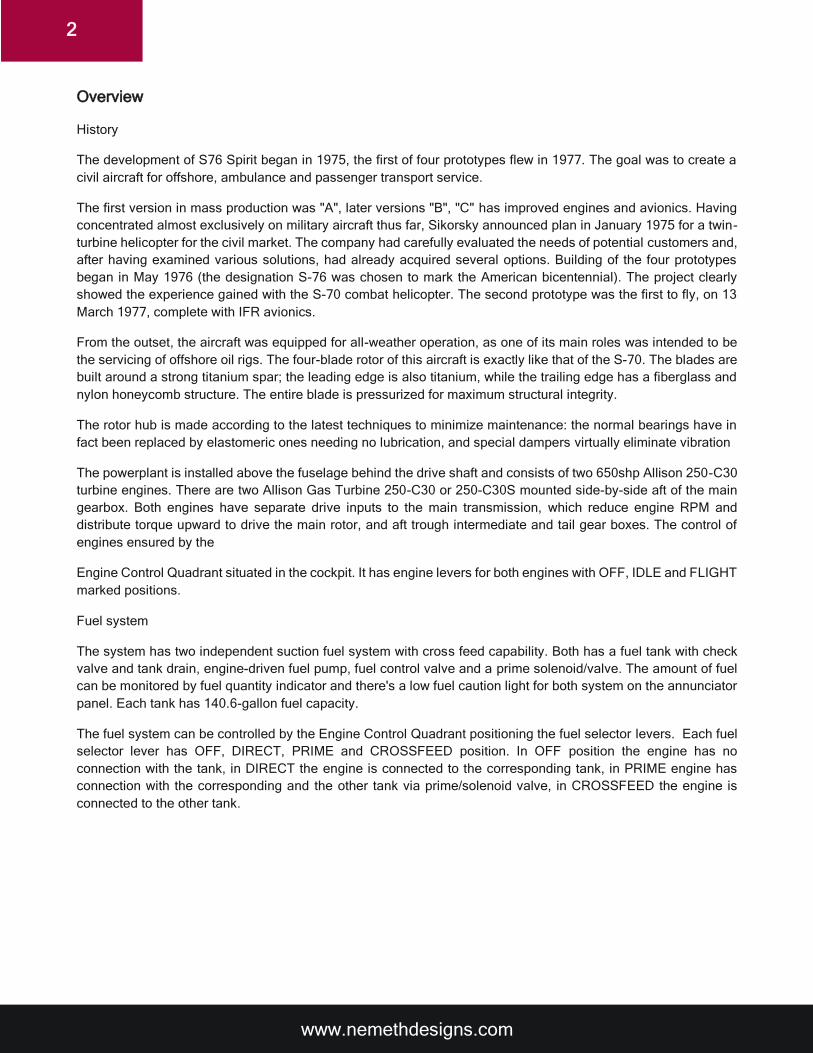
The development of S76 Spirit began in 1975, the first of four prototypes flew in 1977. The goal was to create a
civil aircraft for offshore, ambulance and passenger transport service.
The first version in mass production was "A", later versions "B", "C" has improved engines and avionics. Having
concentrated almost exclusively on military aircraft thus far, Sikorsky announced plan in January 1975 for a twin-
turbine helicopter for the civil market. The company had carefully evaluated the needs of potential customers and,
after having examined various solutions, had already acquired several options. Building of the four prototypes
began in May 1976 (the designation S-76 was chosen to mark the American bicentennial). The project clearly
showed the experience gained with the S-70 combat helicopter. The second prototype was the first to fly, on 13
March 1977, complete with IFR avionics.
From the outset, the aircraft was equipped for all-weather operation, as one of its main roles was intended to be
the servicing of offshore oil rigs. The four-blade rotor of this aircraft is exactly like that of the S-70. The blades are
built around a strong titanium spar; the leading edge is also titanium, while the trailing edge has a fiberglass and
nylon honeycomb structure. The entire blade is pressurized for maximum structural integrity.
The rotor hub is made according to the latest techniques to minimize maintenance: the normal bearings have in
fact been replaced by elastomeric ones needing no lubrication, and special dampers virtually eliminate vibration
The powerplant is installed above the fuselage behind the drive shaft and consists of two 650shp Allison 250-C30
turbine engines. There are two Allison Gas Turbine 250-C30 or 250-C30S mounted side-by-side aft of the main
gearbox. Both engines have separate drive inputs to the main transmission, which reduce engine RPM and
distribute torque upward to drive the main rotor, and aft trough intermediate and tail gear boxes. The control of
engines ensured by the
Engine Control Quadrant situated in the cockpit. It has engine levers for both engines with OFF, IDLE and FLIGHT
marked positions.
Fuel system
The system has two independent suction fuel system with cross feed capability. Both has a fuel tank with check
valve and tank drain, engine-driven fuel pump, fuel control valve and a prime solenoid/valve. The amount of fuel
can be monitored by fuel quantity indicator and there's a low fuel caution light for both system on the annunciator
panel. Each tank has 140.6-gallon fuel capacity.
The fuel system can be controlled by the Engine Control Quadrant positioning the fuel selector levers. Each fuel
selector lever has OFF, DIRECT, PRIME and CROSSFEED position. In OFF position the engine has no
connection with the tank, in DIRECT the engine is connected to the corresponding tank, in PRIME engine has
connection with the corresponding and the other tank via prime/solenoid valve, in CROSSFEED the engine is
connected to the other tank.

www.nemethdesigns.com
3
Rotor system
Four-blade articulated main rotor with one-piece aluminum hub and elastomeric bearings. Main rotor blades with
titanium spars, fiberglass skins and honeycomb cores. Single bifilar vibration suppression system. Nose mounted
vibration absorber, provision for main rotor tracker and tail rotor balancer. There's a four-blade flex-beam tail rotor
installed. The blades are pressurized for maximum structural integrity.
Transmission system
The system consists of three gear boxes with associated shafting witch transmit engine torque to the main gear
box. Each engine connected to the main gear box. The main rotor drive shaft, to which the main rotor system is
attached extends from the main gear box. A drive shaft extends from the main gear box to the intermediate gear
box which is connected to the tail rotor gear box with shafting. An accessory drive section installed to the rear of
the main gear box drives first and second stage hydraulic pumps, two main gear box oil pumps, the main gear box
oil cooler and the AC generator.
Airframe
Nose mounted random, heated glass windshields with windshield wiper and washer. Pilot and Copilot seats with
5 points restraint harness. Two electable hinged cockpit doors left and right-side hinged cabin doors with electric
door locks and single action door release. 204 cubic foot cabin with fittings for up twelve seats. Separate baggage
compartment with dual lockable doors.
Electrical system
The DC power source provided by a 37 amp/hour 24 DC volt NiCad battery, two engine-mounted 28 DC volt
generator and external power supply with overvoltage protection. Normally No.1 DC generator provides No.1 DC
primary bus, essential bus and battery bus also charging the battery. No.2 DC generator feeds No.2 DC primary
bus and inverter. If one DC generator fails, the operational will supply DC power to all system. Caution lights and
an optional volt/amp gauge are used to monitor the DC power system operation. The AC power is provided by a
115 AC volt 3-phase 400Hz MGB driven generator and a 600 VA static inverter fed by 28 DC. The AC generator
and inverter outputs are connected to the AC primary bus contactor feeding the AC No.1 primary, AC No.2 primary
buses and two 115 AC volt/26 AC volt transformers. The two transformers provide 26 AC volt for No.1 and No.2
26 AC volt buses. Caution lights are used to monitor the AC power system operation. Both systems have circuit
breakers to protect electrical devices against circuit overvoltage.
Hydraulic system
The system has four independent subsystems. The first and second-stage systems are to provide hydraulic
actuation of the flight controls. The second stage also provides power to the utility system. Utility system includes
landing gear extend/retraction system, pedal damper and nose vibration absorber. The first and second stage
systems are electrically interconnected, so that one system malfunction occur the other cannot be shut off. The
wheel brake system has independent hydraulic system to provide hydraulic pressure to wheel and parking brake.
The fourth subsystem provides pressure for rotor brake.
Fire protection system
Fire protection includes a fire detection and indicating system, an electrically controlled fixed fire-extinguisher
system for each engine, and a smoke detector for the baggage compartment. The engine fire detection system
uses photocell flame detectors that sense infrared radiation of light, such as flame and cause the proper warning
lights to illuminate. In addition, an audible warning signal notifies the crew of a fire. Smoke detection is provided
by a smoke detector in the baggage compartment.
The detector is located on the forward aft bulkhead, just inside the left baggage compartment door. Engine fire-
extinguishing capability is provided by two pressurized fire extinguisher bottles containing both a fire extinguishing
agent and a propellent. A cross-feed system allows the use of both bottles for a fire in either engine compartment.
www.nemethdesigns.com
4
www.nemethdesigns.com
5
Specifications
Engine: Allison 250 C30S
Takeoff power: 650shp / 485kw
Max continuous: 557shp / 415kw
Rotor Main rotor blade number: 4
Main rotor diameter: 44.00ft / 13,41m
Tail rotor diameter:
Tail rotor blade number: 4
Dimensions Fuselage length: 43,37ft / 13,22m
T/R turning length: 45,20ft / 13,78m
Fuselage width: 7ft / 2,13m
Widest point width: 10,00ft / 3,05m
Landing gear width: 8,46ft / 2.58m
Height top, tail fin: 11,75ft / 3.58
Height top, TR arc: 11,48ft / 4,42m
GR clearance, fuselage: 1,00ft / 0,30m
GR clearance, T/R guard: 6,50ft / 1,98m
Accommodations: 2 + 12/13; 2 + 4
Weights Max gross: 10,500lb / 1763kg
Empty: 5930lb / 2690kg
Useful load: 4570lb / 2073kg
External load: 3300lb / 1497kg
Gross with external load: 10,500lb / 4763kg
Endurance Std fuel, no reserves: 3,5 hrs.
Average fuel consumption: 77-85gph,291-332lph
Range Max fuel: 404nm / 749km
Max payload: 404nm / 749km
Aux fuel, no reserves: 462nm / 1042km
Performance Service ceiling: 14,100 ft / 4310m
HIGE: 2400ft / 732m
HOGE: 1200ft / 366m
ROC, oblique: 1350fpm / 411m/min
Econ cruise, S/L: 135kts / 250km/h
VNE: 155kts / 187km/h
www.nemethdesigns.com
6
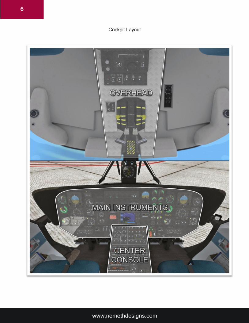
Cockpit Layout
www.nemethdesigns.com
7
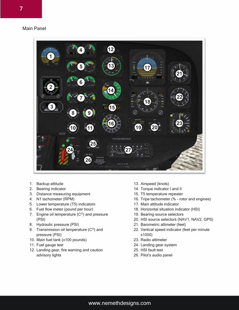
Main Panel
1. Backup attitude
2. Bearing indicator
3. Distance measuring equipment
4. N1 tachometer (RPM)
5. Lower temperature (T5) indicators
6. Fuel flow meter (pound per hour)
7. Engine oil temperature (CO) and pressure
(PSI)
8. Hydraulic pressure (PSI)
9. Transmission oil temperature (CO) and
pressure (PSI)
10. Main fuel tank (x100 pounds)
11. Fuel gauge test
12. Landing gear, fire warning and caution
advisory lights
13. Airspeed (knots)
14. Torque indicator I and II
15. T5 temperature repeater
16. Tripe tachometer (% - rotor and engines)
17. Main attitude indicator
18. Horizontal situation indicator (HSI)
19. Bearing source selectors
20. HSI source selectors (NAV1, NAV2, GPS)
21. Barometric altimeter (feet)
22. Vertical speed indicator (feet per minute
x1000)
23. Radio altimeter
24. Landing gear system
25. HSI fault test
26. Pilot’s audio panel
www.nemethdesigns.com
8
The bearing indicator (2.) consists of two needles. The source for these needles can be selected with the
bearing source switches (19.) under the HSI indicator. Both needles can be set to either show the ADF bearing
or individually the yellow for the NAV2 bearing and the green for the NAV1 bearing. The values of the selected
bearings are also indicated on the top left and right corners of the display when signal is present.
By default, the distance measuring equipment (3.) shows the distance to the selected NAV source (NAV1 or
NAV2) that is set with the small source selector knob. It can also be set to indicate the estimated time to the
destination transmitter or waypoint; or the ground speed with the buttons below the screen.
The main attitude indicator (17.) has two small displays on the bottom right and left corners of the instrument.
The left shows the value of the preset decision height (DH) that is set on the radar altimeter gauge (23.) The
right shows the value of the measured distance to the surface below the aircraft. The small green arrows on
the left indicate the tendency of descend or ascend. The scale on the bottom is the localizer deviation indicator
and the scale on the right side is the glide slope deviation indicator.
The Horizontal Situation Indicator (18.) consists of the main compass with the course deviation indicator and
heading marker, the distance to waypoint indicator on the top-left corner, the course indicator on the top-right
corner, the glide slope indicators on both sides of the compass, and the heading marker and course selector
knobs on the bottom of the instrument. The indicated NAV source can be selected with the NAV source
selector switches (20.) below the HSI indicator.
The landing gear control consists of the main landing gear lever, the landing gear position indicator lights, the
emergency extension lever and the system movement (unlocked) indicator light. The emergency extension
lever pulls the landing gears down with the force of gravity and locks them into the extended position after
which the landing gears cannot be retracted. The unlocked indicator light indicated that the gears are between
the retracted and extended positions.
www.nemethdesigns.com
9
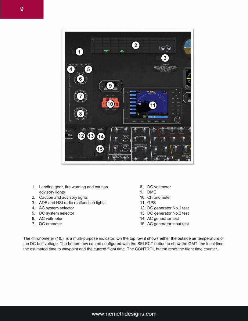
1. Landing gear, fire warning and caution
advisory lights
2. Caution and advisory lights
3. ADF and HSI radio malfunction lights
4. AC system selector
5. DC system selector
6. AC voltmeter
7. DC ammeter
8. DC voltmeter
9. DME
10. Chronometer
11. GPS
12. DC generator No.1 test
13. DC generator No.2 test
14. AC generator test
15. AC generator input test
The chronometer (10.) is a multi-purpose indicator. On the top row it shows either the outside air temperature or
the DC bus voltage. The bottom row can be configured with the SELECT button to show the GMT, the local time,
the estimated time to waypoint and the current flight time. The CONTROL button reset the flight time counter.
www.nemethdesigns.com
10
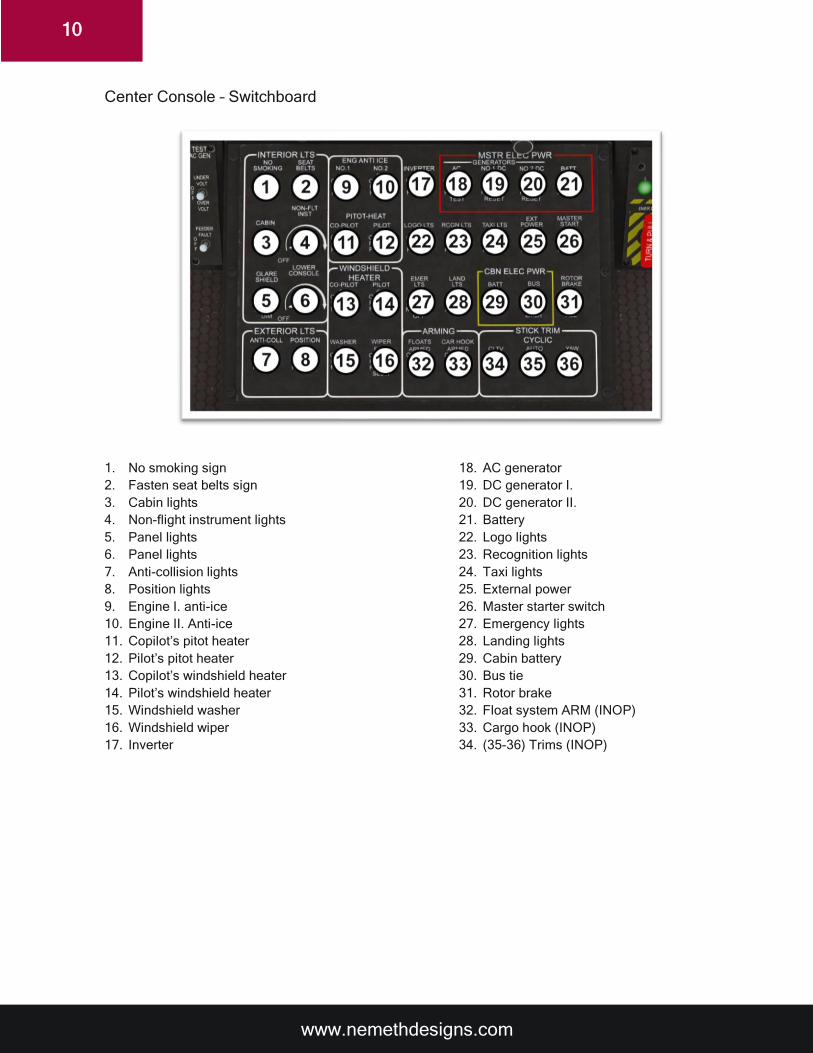
Center Console – Switchboard
1. No smoking sign
2. Fasten seat belts sign
3. Cabin lights
4. Non-flight instrument lights
5. Panel lights
6. Panel lights
7. Anti-collision lights
8. Position lights
9. Engine I. anti-ice
10. Engine II. Anti-ice
11. Copilot’s pitot heater
12. Pilot’s pitot heater
13. Copilot’s windshield heater
14. Pilot’s windshield heater
15. Windshield washer
16. Windshield wiper
17. Inverter
18. AC generator
19. DC generator I.
20. DC generator II.
21. Battery
22. Logo lights
23. Recognition lights
24. Taxi lights
25. External power
26. Master starter switch
27. Emergency lights
28. Landing lights
29. Cabin battery
30. Bus tie
31. Rotor brake
32. Float system ARM (INOP)
33. Cargo hook (INOP)
34. (35-36) Trims (INOP)

www.nemethdesigns.com
11
Center Console – Radios
1. Com radio I.
2. Com radio II.
3. Navigation radio I.
4. Navigation radio II.
5. ADF radio
6. Transponder
7. AFCS (Automatic Flight Control System)
8. AFCS mode indicator
9. Audio panel
10. Instrument lights
11. Door status indicators
12. Servos ON/OFF
The NAVCOM radios (1.-4.) can be turned ON and switched OFF with the small ON/OFF knobs. The standby
frequencies can be set with the frequency setting knobs on the bottom-right corners of the instruments. The
large knobs set the whole MHz and the small set the fraction of a MHz The active and standby frequencies
can be swapped with the small white swapper buttons.
On the ADF radio (5.) the frequency of the Non-Direction Beacon (NDB) transmitter can be set with the
frequency setting knobs on the right side of the instrument. This instrument also shows the estimated arrival
time to the transmitter and the current flight time. These functions can be selected with the ET and FLT buttons.
The SET button resets the flight time counter.
The squawk code can be set on the transponder (6.) with the numeric buttons after pressing the SET button
on the instrument then pressing the SET again to confirm. The VFR button activates the 1200 VFR squawk
code regardless of what was preset.
Unlike the real one, the AFCS system (7.-8.) in this addon has a very limited functionality and works only in
P3D. It can hold heading and vertical speed as well as altitude but cannot hold more difficult patterns governed
www.nemethdesigns.com
12
by flight directors. It can also auto-hover to a certain degree. Pressing the AP button midflight activates the
autopilot which is indicated with a green light on the button. Upon activation the AFCS holds the current input
values that are on the flight instruments. For instance, if the aircraft is in a descend with a particular vertical
speed when the AP button was pressed then it tries to hold that value. The pitch can be adjusted manually in
this mode and the AP tries to hold the pitch value that is adjusted with the cycle. The SAS/ATT button holds
the current altitude. Pressing the AP button again disengages the AFCS system and resets the values to zero.
The ADCS can be activated with the default P3D autopilot engage/disengage key and the SAS/ATT function
can be activated with the default altitude P3D hold key.
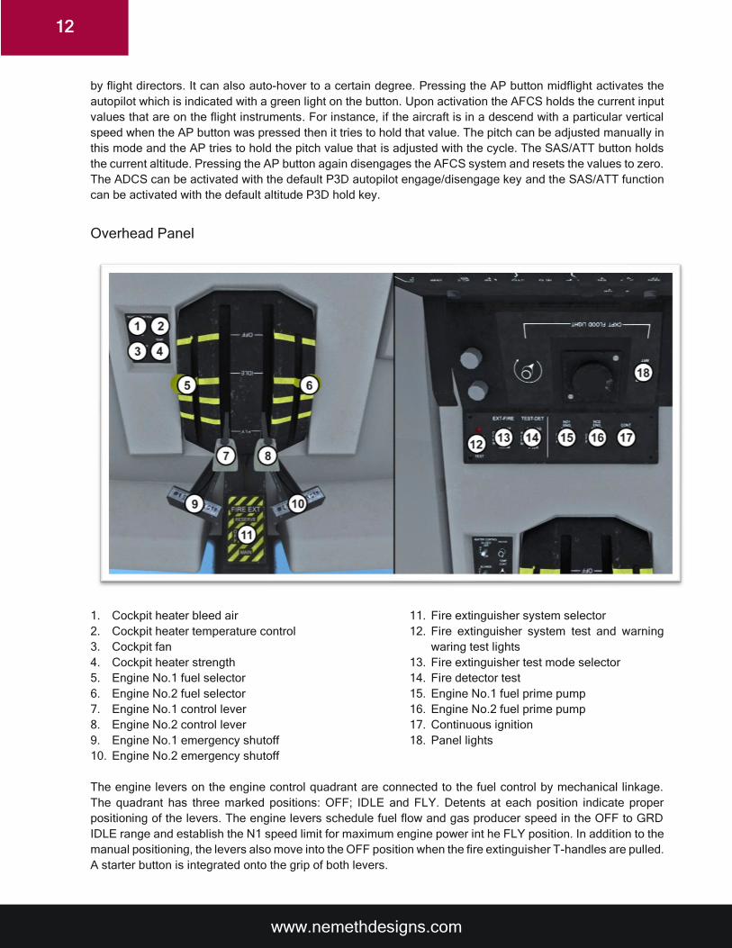
Overhead Panel
1. Cockpit heater bleed air
2. Cockpit heater temperature control
3. Cockpit fan
4. Cockpit heater strength
5. Engine No.1 fuel selector
6. Engine No.2 fuel selector
7. Engine No.1 control lever
8. Engine No.2 control lever
9. Engine No.1 emergency shutoff
10. Engine No.2 emergency shutoff
11. Fire extinguisher system selector
12. Fire extinguisher system test and warning
waring test lights
13. Fire extinguisher test mode selector
14. Fire detector test
15. Engine No.1 fuel prime pump
16. Engine No.2 fuel prime pump
17. Continuous ignition
18. Panel lights
The engine levers on the engine control quadrant are connected to the fuel control by mechanical linkage.
The quadrant has three marked positions: OFF; IDLE and FLY. Detents at each position indicate proper
positioning of the levers. The engine levers schedule fuel flow and gas producer speed in the OFF to GRD
IDLE range and establish the N1 speed limit for maximum engine power int he FLY position. In addition to the
manual positioning, the levers also move into the OFF position when the fire extinguisher T-handles are pulled.
A starter button is integrated onto the grip of both levers.
www.nemethdesigns.com
13
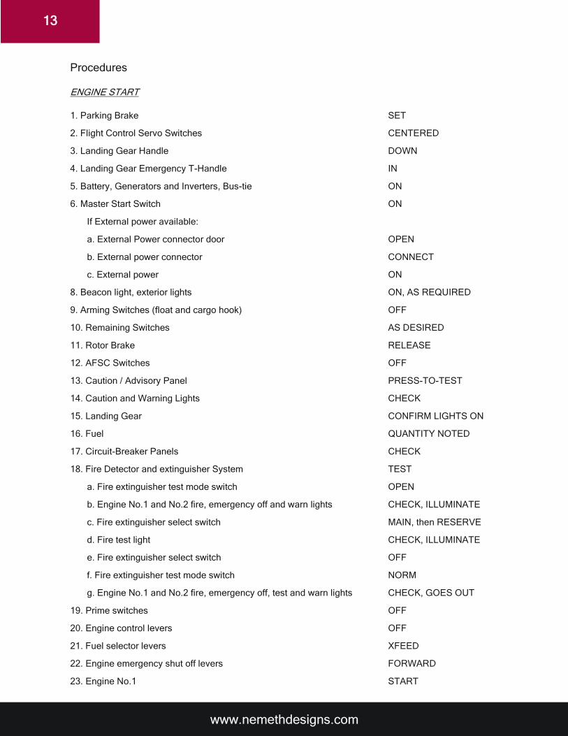
Procedures
ENGINE START
1. Parking Brake SET
2. Flight Control Servo Switches CENTERED
3. Landing Gear Handle DOWN
4. Landing Gear Emergency T-Handle IN
5. Battery, Generators and Inverters, Bus-tie ON
6. Master Start Switch ON
If External power available:
a. External Power connector door OPEN
b. External power connector CONNECT
c. External power ON
8. Beacon light, exterior lights ON, AS REQUIRED
9. Arming Switches (float and cargo hook) OFF
10. Remaining Switches AS DESIRED
11. Rotor Brake RELEASE
12. AFSC Switches OFF
13. Caution / Advisory Panel PRESS-TO-TEST
14. Caution and Warning Lights CHECK
15. Landing Gear CONFIRM LIGHTS ON
16. Fuel QUANTITY NOTED
17. Circuit-Breaker Panels CHECK
18. Fire Detector and extinguisher System TEST
a. Fire extinguisher test mode switch OPEN
b. Engine No.1 and No.2 fire, emergency off and warn lights CHECK, ILLUMINATE
c. Fire extinguisher select switch MAIN, then RESERVE
d. Fire test light CHECK, ILLUMINATE
e. Fire extinguisher select switch OFF
f. Fire extinguisher test mode switch NORM
g. Engine No.1 and No.2 fire, emergency off, test and warn lights CHECK, GOES OUT
19. Prime switches OFF
20. Engine control levers OFF
21. Fuel selector levers XFEED
22. Engine emergency shut off levers FORWARD
23. Engine No.1 START
www.nemethdesigns.com
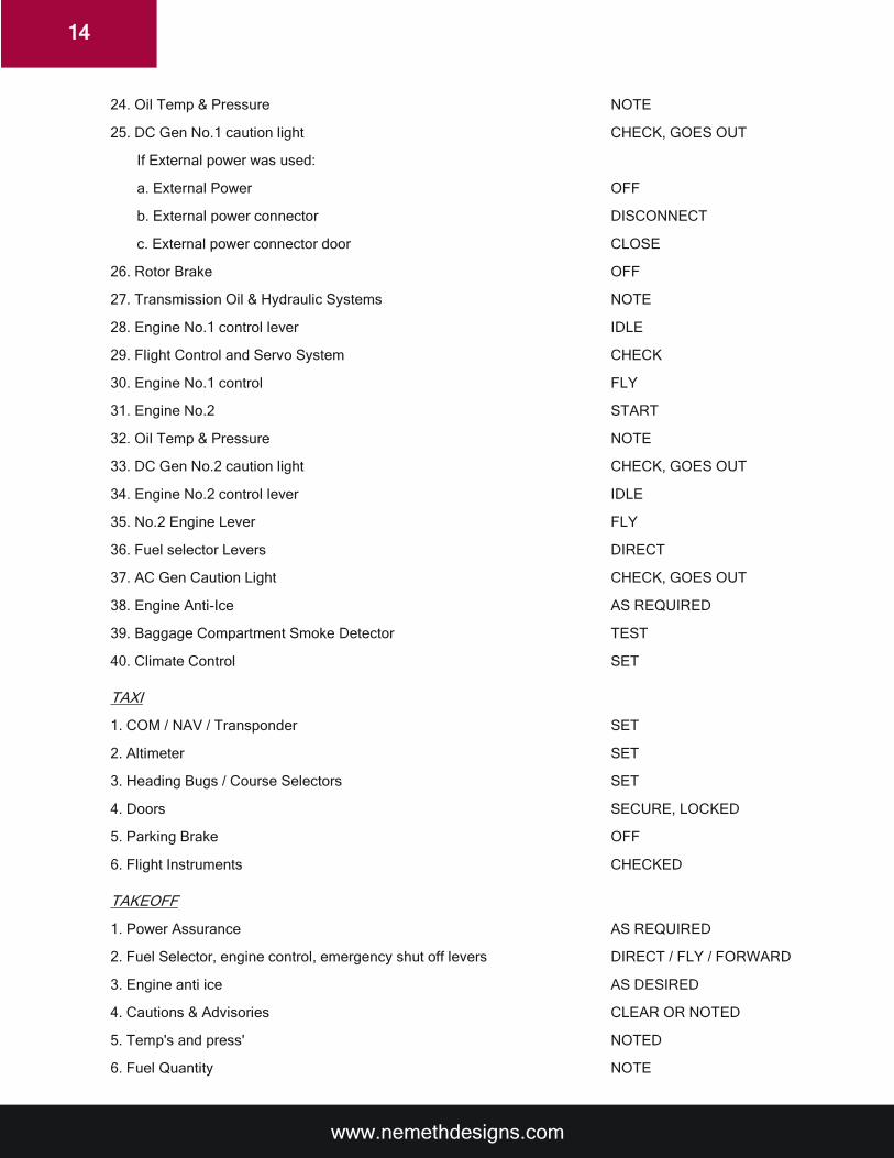
14
24. Oil Temp & Pressure NOTE
25. DC Gen No.1 caution light CHECK, GOES OUT
If External power was used:
a. External Power OFF
b. External power connector DISCONNECT
c. External power connector door CLOSE
26. Rotor Brake OFF
27. Transmission Oil & Hydraulic Systems NOTE
28. Engine No.1 control lever IDLE
29. Flight Control and Servo System CHECK
30. Engine No.1 control FLY
31. Engine No.2 START
32. Oil Temp & Pressure NOTE
33. DC Gen No.2 caution light CHECK, GOES OUT
34. Engine No.2 control lever IDLE
35. No.2 Engine Lever FLY
36. Fuel selector Levers DIRECT
37. AC Gen Caution Light CHECK, GOES OUT
38. Engine Anti-Ice AS REQUIRED
39. Baggage Compartment Smoke Detector TEST
40. Climate Control SET
TAXI
1. COM / NAV / Transponder SET
2. Altimeter SET
3. Heading Bugs / Course Selectors SET
4. Doors SECURE, LOCKED
5. Parking Brake OFF
6. Flight Instruments CHECKED
TAKEOFF
1. Power Assurance AS REQUIRED
2. Fuel Selector, engine control, emergency shut off levers DIRECT / FLY / FORWARD
3. Engine anti ice AS DESIRED
4. Cautions & Advisories CLEAR OR NOTED
5. Temp's and press' NOTED
6. Fuel Quantity NOTE
www.nemethdesigns.com
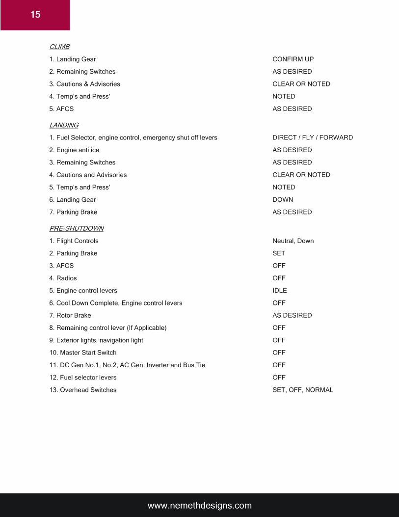
15
CLIMB
1. Landing Gear CONFIRM UP
2. Remaining Switches AS DESIRED
3. Cautions & Advisories CLEAR OR NOTED
4. Temp’s and Press' NOTED
5. AFCS AS DESIRED
LANDING
1. Fuel Selector, engine control, emergency shut off levers DIRECT / FLY / FORWARD
2. Engine anti ice AS DESIRED
3. Remaining Switches AS DESIRED
4. Cautions and Advisories CLEAR OR NOTED
5. Temp’s and Press' NOTED
6. Landing Gear DOWN
7. Parking Brake AS DESIRED
PRE-SHUTDOWN
1. Flight Controls Neutral, Down
2. Parking Brake SET
3. AFCS OFF
4. Radios OFF
5. Engine control levers IDLE
6. Cool Down Complete, Engine control levers OFF
7. Rotor Brake AS DESIRED
8. Remaining control lever (If Applicable) OFF
9. Exterior lights, navigation light OFF
10. Master Start Switch OFF
11. DC Gen No.1, No.2, AC Gen, Inverter and Bus Tie OFF
12. Fuel selector levers OFF
13. Overhead Switches SET, OFF, NORMAL

www.nemethdesigns.com
16
Nemeth Designs Development Group
©2019 All rights reserved