Embed Size (px)
Citation preview
DIgSILENT Pacific Technical Seminar 2012 1
DIgSILENT Pacific Technical Seminar 2012
NEM Grid Connection and Generator
Compliance
Presenter: Tony Bertes
DIgSILENT Pacific
2 2
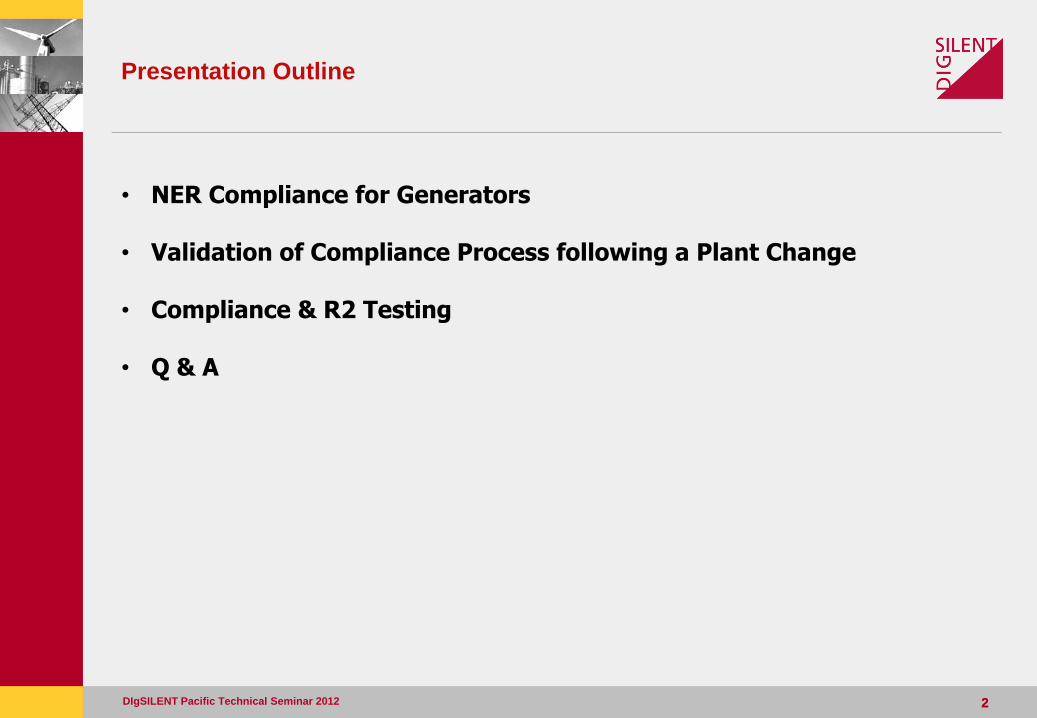
Presentation Outline
• NER Compliance for Generators
• Validation of Compliance Process following a Plant Change
• Compliance & R2 Testing
• Q & A
DIgSILENT Pacific Technical Seminar 2012
The Need for Compliance
DIgSILENT Pacific Technical Seminar 2012 3
Section 1
NER Compliance for Generators
4 4
NER Compliance for Generators
- The integration of generation into the power system must be coordinated so that levels of quality, reliability of supply and power system security can be maintained
- Reliable and secure operation of a power system is tied to the ability of its mix of generation, transmission, and loads to operate under a variety of conditions
- For this reason, the NER includes processes to coordinate the technical interaction between new and existing generation and the power system
DIgSILENT Pacific Technical Seminar 2012
5 5
NER Compliance for Generators
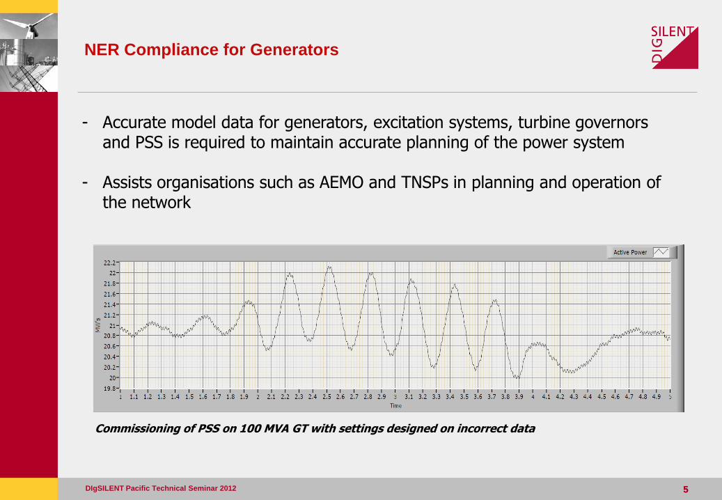
- Accurate model data for generators, excitation systems, turbine governors and PSS is required to maintain accurate planning of the power system
- Assists organisations such as AEMO and TNSPs in planning and operation of the network
DIgSILENT Pacific Technical Seminar 2012
Commissioning of PSS on 100 MVA GT with settings designed on incorrect data
6 6
NER Compliance for Generators – Performance Standards
- Rules specify each generating unit must meet a number of technical requirements and these form part of the technical terms and conditions of the Connection Agreement
- These are met by ensuring generators meet a range of Generator Performance Standards (GPS)
- The Rules allow performance standards to be negotiated between the Proponent, the NSP, and AEMO
- An access standard is a benchmark for determining the appropriate performance standard for each unit:
- Minimum Access Standard - Automatic Access Standard - Negotiated Access Standard
DIgSILENT Pacific Technical Seminar 2012
7 7
NER Compliance for Generators – Performance Standards
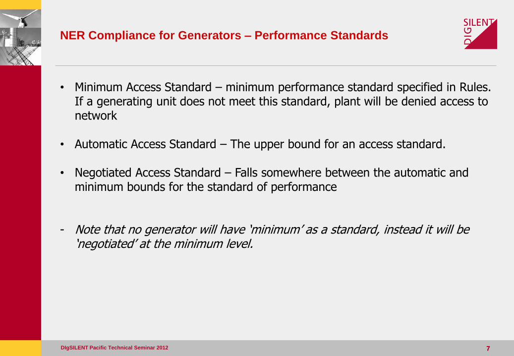
• Minimum Access Standard – minimum performance standard specified in Rules. If a generating unit does not meet this standard, plant will be denied access to network
• Automatic Access Standard – The upper bound for an access standard.
• Negotiated Access Standard – Falls somewhere between the automatic and minimum bounds for the standard of performance
- Note that no generator will have ‘minimum’ as a standard, instead it will be ‘negotiated’ at the minimum level.
DIgSILENT Pacific Technical Seminar 2012
Validation of Compliance Process following a Plant Change
DIgSILENT Pacific Technical Seminar 2012 8
Section 2
Validation of Compliance Process
following a Plant Change
9 9
Validation of Compliance Process following a Plant Change
DIgSILENT Pacific Technical Seminar 2012
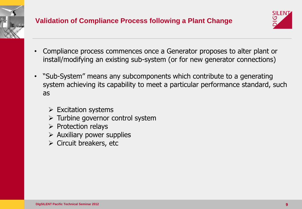
• Compliance process commences once a Generator proposes to alter plant or install/modifying an existing sub-system (or for new generator connections)
• “Sub-System” means any subcomponents which contribute to a generating system achieving its capability to meet a particular performance standard, such as Excitation systems Turbine governor control system Protection relays Auxiliary power supplies Circuit breakers, etc
10 10
Validation of Compliance Process following a Plant Change
DIgSILENT Pacific Technical Seminar 2012
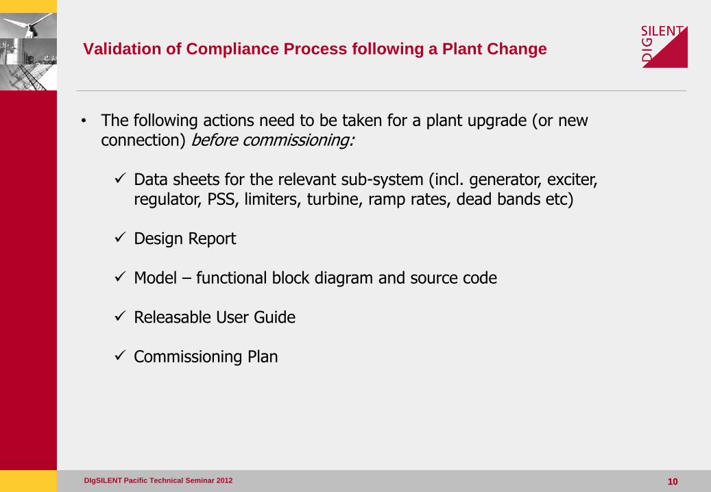
• The following actions need to be taken for a plant upgrade (or new connection) before commissioning: Data sheets for the relevant sub-system (incl. generator, exciter,
regulator, PSS, limiters, turbine, ramp rates, dead bands etc) Design Report Model – functional block diagram and source code Releasable User Guide Commissioning Plan
11 11
Validation of Compliance Process following a Plant Change – Data
sheets
DIgSILENT Pacific Technical Seminar 2012
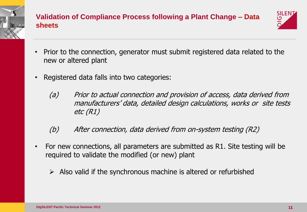
• Prior to the connection, generator must submit registered data related to the new or altered plant
• Registered data falls into two categories:
(a) Prior to actual connection and provision of access, data derived from manufacturers’ data, detailed design calculations, works or site tests etc (R1)
(b) After connection, data derived from on-system testing (R2)
• For new connections, all parameters are submitted as R1. Site testing will be required to validate the modified (or new) plant Also valid if the synchronous machine is altered or refurbished
12 12
Validation of Compliance Process following a Plant Change – Data
sheets
DIgSILENT Pacific Technical Seminar 2012
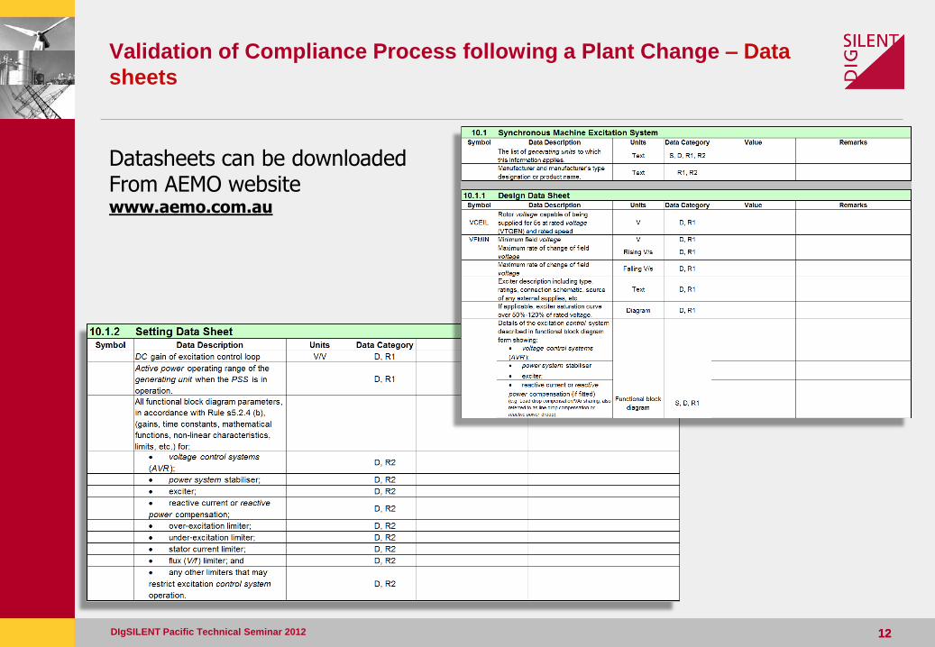
Datasheets can be downloaded From AEMO website www.aemo.com.au
13 13
Validation of Compliance Process following a Plant Change – Design
Report
DIgSILENT Pacific Technical Seminar 2012
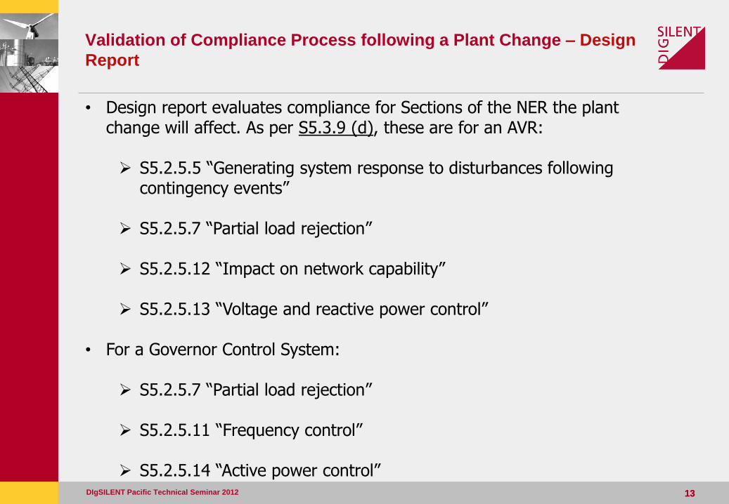
• Design report evaluates compliance for Sections of the NER the plant change will affect. As per S5.3.9 (d), these are for an AVR: S5.2.5.5 “Generating system response to disturbances following
contingency events” S5.2.5.7 “Partial load rejection” S5.2.5.12 “Impact on network capability”
S5.2.5.13 “Voltage and reactive power control”
• For a Governor Control System:
S5.2.5.7 “Partial load rejection”
S5.2.5.11 “Frequency control”
S5.2.5.14 “Active power control”
Validation of Compliance Process following a Plant Change of an
AVR
DIgSILENT Pacific Technical Seminar 2012 14
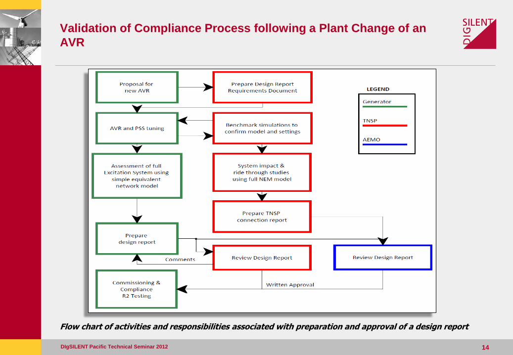
Flow chart of activities and responsibilities associated with preparation and approval of a design report
15 15
Validation of Compliance Process following a Plant Change – Design
Report
DIgSILENT Pacific Technical Seminar 2012
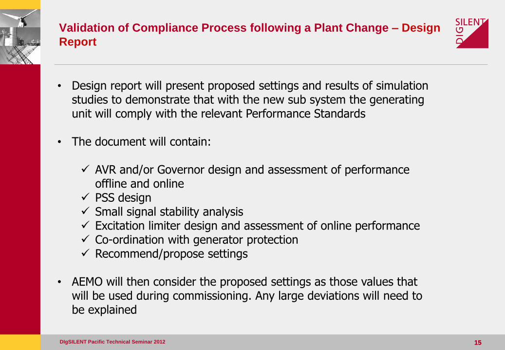
• Design report will present proposed settings and results of simulation studies to demonstrate that with the new sub system the generating unit will comply with the relevant Performance Standards
• The document will contain: AVR and/or Governor design and assessment of performance
offline and online PSS design Small signal stability analysis Excitation limiter design and assessment of online performance Co-ordination with generator protection Recommend/propose settings
• AEMO will then consider the proposed settings as those values that will be used during commissioning. Any large deviations will need to be explained
16 16
Validation of Compliance Process following a Plant Change –
S5.2.5.13
DIgSILENT Pacific Technical Seminar 2012
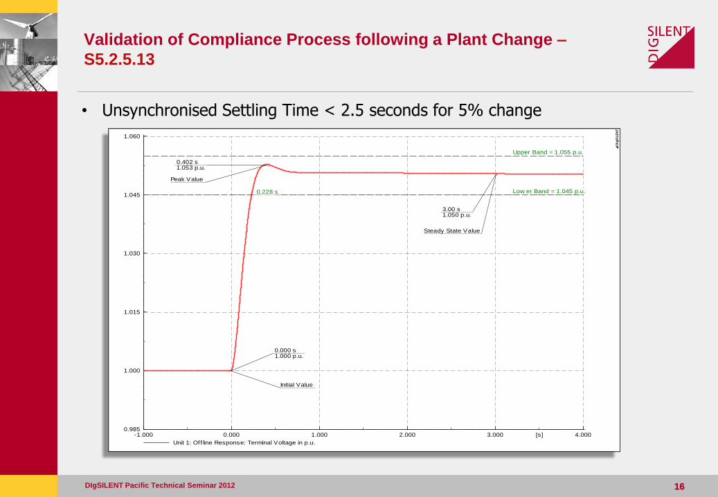
• Unsynchronised Settling Time < 2.5 seconds for 5% change
4.0003.0002.0001.0000.000-1.000 [s]
1.060
1.045
1.030
1.015
1.000
0.985
Unit 1: Off line Response: Terminal Voltage in p.u.
0.000 s 1.000 p.u.
Upper Band = 1.055 p.u.
Low er Band = 1.045 p.u. 0.228 s
3.00 s 1.050 p.u.
0.402 s 1.053 p.u.
Steady State Value
Peak Value
Initial Value
DIg
SIL
EN
T
17 17
Validation of Compliance Process following a Plant Change –
S5.2.5.13
DIgSILENT Pacific Technical Seminar 2012
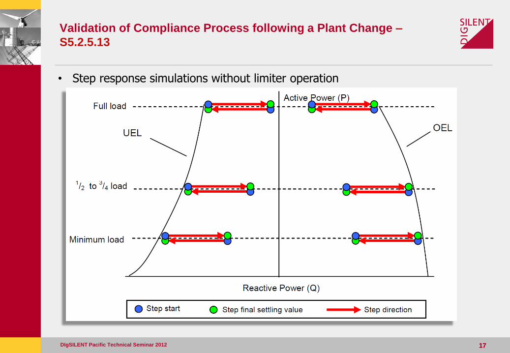
• Step response simulations without limiter operation
18 18
Validation of Compliance Process following a Plant Change –
S5.2.5.13
DIgSILENT Pacific Technical Seminar 2012
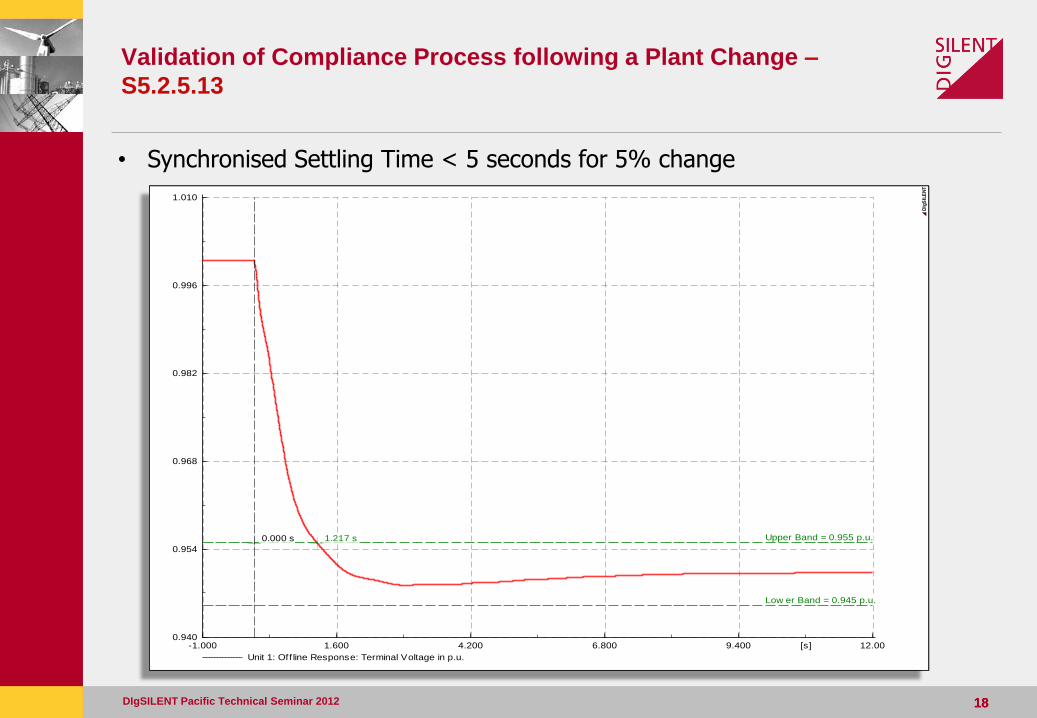
• Synchronised Settling Time < 5 seconds for 5% change
12.009.4006.8004.2001.600-1.000 [s]
1.010
0.996
0.982
0.968
0.954
0.940
Unit 1: Off line Response: Terminal Voltage in p.u.
Upper Band = 0.955 p.u. 1.217 s 0.000 s
Low er Band = 0.945 p.u.
DIg
SIL
EN
T
19 19
Validation of Compliance Process following a Plant Change –
S5.2.5.13
DIgSILENT Pacific Technical Seminar 2012
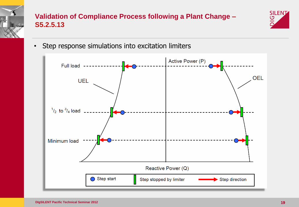
• Step response simulations into excitation limiters
20 20
Validation of Compliance Process following a Plant Change –
S5.2.5.13
DIgSILENT Pacific Technical Seminar 2012
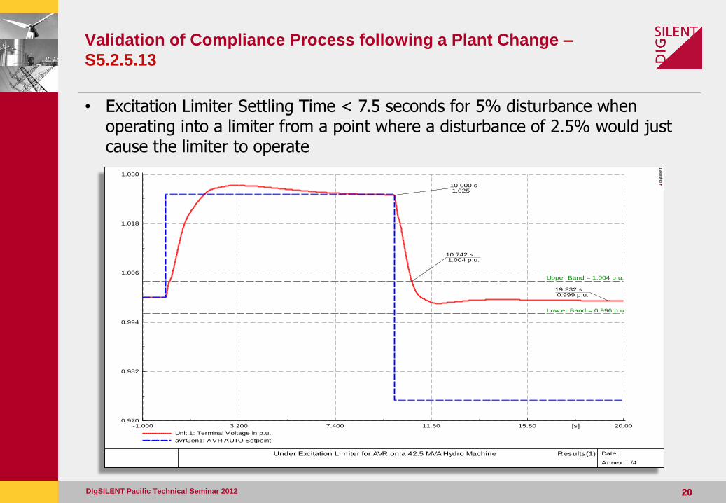
• Excitation Limiter Settling Time < 7.5 seconds for 5% disturbance when
operating into a limiter from a point where a disturbance of 2.5% would just cause the limiter to operate
20.0015.8011.607.4003.200-1.000 [s]
1.030
1.018
1.006
0.994
0.982
0.970
Unit 1: Terminal Voltage in p.u.
avrGen1: AVR AUTO Setpoint
19.332 s 0.999 p.u.
Upper Band = 1.004 p.u.
Low er Band = 0.996 p.u.
10.000 s 1.025
10.742 s 1.004 p.u.
Under Excitation Limiter for AVR on a 42.5 MVA Hydro Machine Results(1)
Date:
Annex: /4
DIg
SIL
EN
T

Validation of Compliance Process following a Plant Change –
S5.2.5.13
• Impact of Connecting a Generating Unit with PSS
DIgSILENT Pacific Technical Seminar 2012 21
0.5
1
1.5
2
2.5
3
3.5
4
4.5
5
-20 -15 -10 -5 0
Da
mp
ed
Fre
qu
en
cy (
Hz)
Damping Coefficient (Np.s-1)
With GenNew
No GenNew
Stability Margin
Validation of Compliance Process following a Plant Change –
S5.2.5.13
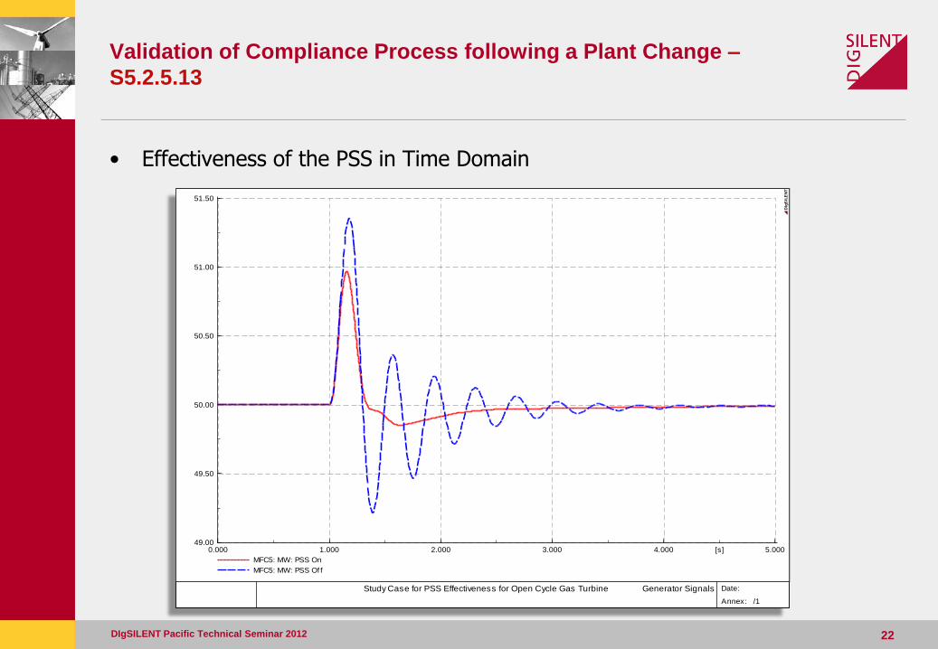
• Effectiveness of the PSS in Time Domain
DIgSILENT Pacific Technical Seminar 2012 22
5.0004.0003.0002.0001.0000.000 [s]
51.50
51.00
50.50
50.00
49.50
49.00
MFC5: MW: PSS On
MFC5: MW: PSS Of f
Study Case for PSS Effectiveness for Open Cycle Gas Turbine Generator Signals
Date:
Annex: /1
DIg
SIL
EN
T
Validation of Compliance Process following a Plant Change –
S5.2.5.7
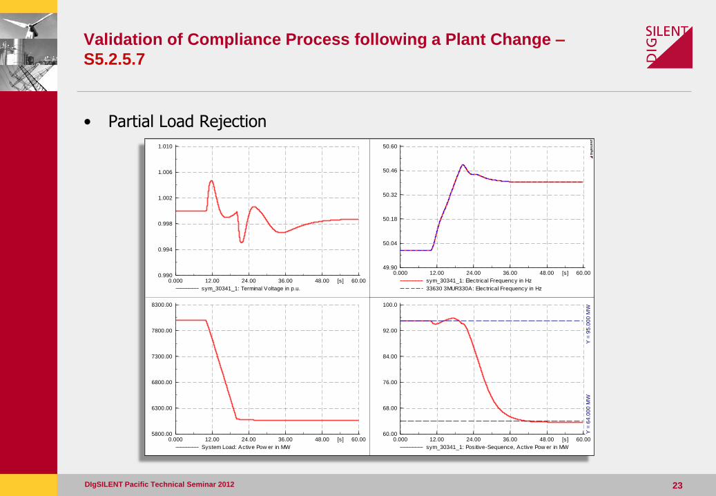
• Partial Load Rejection
DIgSILENT Pacific Technical Seminar 2012 23
60.0048.0036.0024.0012.000.000 [s]
100.0
92.00
84.00
76.00
68.00
60.00
sym_30341_1: Positive-Sequence, Active Pow er in MW
Y =
95
.00
0 M
WY
= 6
4.0
00
MW
60.0048.0036.0024.0012.000.000 [s]
50.60
50.46
50.32
50.18
50.04
49.90
sym_30341_1: Electrical Frequency in Hz
33630 3MUR330A: Electrical Frequency in Hz
60.0048.0036.0024.0012.000.000 [s]
1.010
1.006
1.002
0.998
0.994
0.990
sym_30341_1: Terminal Voltage in p.u.
60.0048.0036.0024.0012.000.000 [s]
8300.00
7800.00
7300.00
6800.00
6300.00
5800.00
System Load: Active Pow er in MW
DIg
SIL
EN
T
24 24
Validation of Compliance Process following a Plant Change –
Functional Block Diagram
DIgSILENT Pacific Technical Seminar 2012
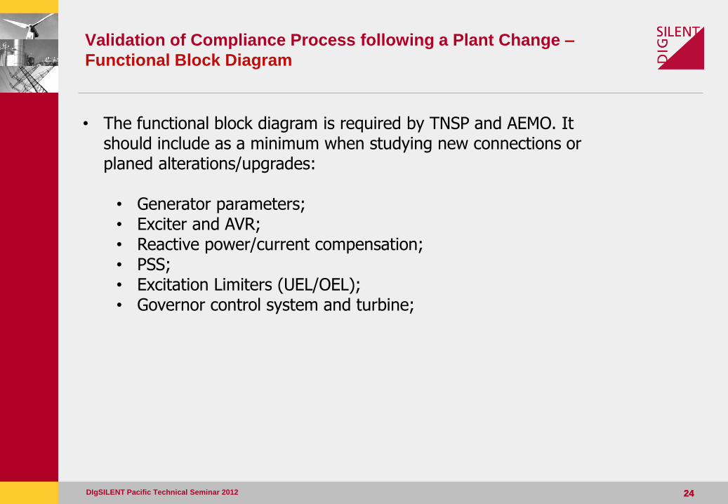
• The functional block diagram is required by TNSP and AEMO. It should include as a minimum when studying new connections or planed alterations/upgrades: • Generator parameters; • Exciter and AVR; • Reactive power/current compensation; • PSS; • Excitation Limiters (UEL/OEL); • Governor control system and turbine;
25 25
Validation of Compliance Process following a Plant Change –
Functional Block Diagram (cont.)
DIgSILENT Pacific Technical Seminar 2012
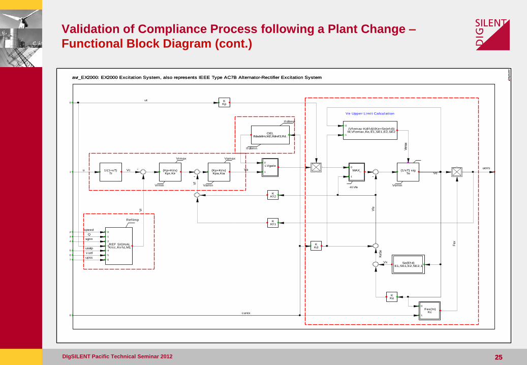
avr_EX2000: EX2000 Excitation System, also represents IEEE Type AC7B Alternator-Rectifier Excitation System
Ve Upper Limit Calculation
-Kl.Vfe
OELIfdadvlim,M2,Ifdref3,Ifd..
If dlimp
If dlimn
KKf 1
KKf 2
-
{Kp+Ki/s}Kpr,Kir
Vrmax
Vrmin
{Kp+Ki/s}Kpa,Kia
Vamax
Vamin
KKp
Fex(In)Kc
0
1
MAX_0
1
LVgate0
1
-
{1/sT} sigTe
Vemin
-
Se(Ef d)E1,SE1,E2,SE2,1
KKd
KKe
(Vf emax-KdIf d)/(Ke+Se(ef d))M,Vf emax,Ke,E1,SE1,E2,SE2
0
1
REF SIGNALKrcc,Kv hz,M1
Ref limp
0
1
2
3
4
5
6
1/(1+sT)Tr
avr_EX2000: EX2000 Excitation System, also represents IEEE Type AC7B Alternator-Rectifier Excitation System
1
8
0
2
3
4
5
6
7
ut
upss
v uel
usetp
Vfe
Ke
Se
sgnn
Q
speed
Vr
uerrs
Vf
Va
Vx
curex
Fe
x
VcuVe
Vem
ax
DIg
SIL
EN
T
26 26
Validation of Compliance Process following a Plant Change –
Functional Block Diagram (cont.)
DIgSILENT Pacific Technical Seminar 2012
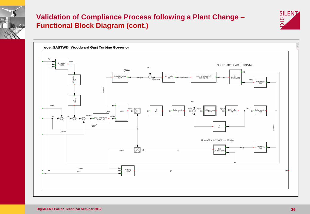
gov_GASTWD: Woodward Gast Turbine Governor
TC
f2 = af2 + bf2*Wf2 + cf2*dw
f1 = Tr - af1*(1-Wf1) + bf1*dw
K6
(1+sTb)/sTa}Tt,T5
Max
-_1/(1+sT)_
T4K4 + K5/(1+sT3)
K4,K5,T3F1
Tr,af 1,bf 1
-
Delay_no_incEtd
PtdbPgTrate
F2af 2,bf 2,cf 2
_1/(1+sT)_Tcd
Delay_no_incEcr
KKf
1/(1+sT)Tf
Valv e_posa,b,c
-
Delay_no_incT
KK3
-
MIN
{Kp+sKd+Ki/s}Kp,Ki,Kd
Max
Min
KK
droo
p1/
(1+s
T)
Td
P_baseTrate
gov_GASTWD: Woodward Gast Turbine Governor
psetp
pgen
wref
pgt
tempin
tem
pout
spcinp
thcouout
dw
radshout f 1
Wf 1
pt
cosn
sgnn
ptnn f 2
Wf 2
com
bout
Wfvpoutv pin
w
fcoutminout
spcout
DIg
SIL
EN
T
27 27
Validation of Compliance Process following a Plant Change – Model
Source Code
DIgSILENT Pacific Technical Seminar 2012
• As per AEMO Model Guidelines and Clause S5.2.4(b)(6), model source code must be provided in an unencrypted form suitable for at least one of the software simulation products nominated by AEMO • PSS/E • PowerFactory • TSAT
• The model source code is expected to contain the model of the plant being altered/upgraded, and any other plant that might have an impact on the unit or system performance
Source: AEMO (http://www.aemo.com.au/registration/118-0001.html)
28 28
Validation of Compliance Process following a Plant Change –
Releasable User Guide
DIgSILENT Pacific Technical Seminar 2012
• As per AEMO Model Guidelines and Clause S5.2.4(b)(6), the generator must also provide a Releasable User Guide (RUG)
• The RUG is a document associated with the functional block diagram and model source code and explains how to include the plant in the system model
• It must contain sufficient information so that a Registered Participant can use the encrypted model source code to carry out studies
• It should contain (but not limited to) Model parameters and values Instructions on how to use the encrypted model source code Connection point details Commissioning dates
29 29
Validation of Compliance Process following a Plant Change –
Commissioning Plan
DIgSILENT Pacific Technical Seminar 2012
• The generator must supply detailed commissioning program 3 months in advance (for transmission connected generator) as per S5.2.4 of the NER
• The TNSP and AEMO must agree with the program and have the right to witness commissioning tests
Compliance & R2 Testing
DIgSILENT Pacific Technical Seminar 2012 30
Section 3
Compliance & R2 Testing
Compliance & R2 Testing
• Compliance Testing is the process of performing on-site tests to evaluate compliance with the relevant Performance Standards affected by the upgrade
• R2 testing is the process of performing on-site tests to validate R1 data
• “Type-testing” of plant is permissible, but excludes plant that has settings that can be applied on-site
– R2 and Compliance testing is required on all AVR’s and turbine governors of each unit
– Type testing is possible on machinery, i.e. Synchronous Generators, Rotating Exciters
DIgSILENT Pacific Technical Seminar 2012 31
Compliance & R2 Testing – Compliance Program
• The onus is on the generator and their consultants to develop a “Compliance Program”
• A Reliability Panel, put together by the AEMC, have developed a template that Generators can follow to develop a “Compliance Program”
– www.aemc.gov.au/Market-Reviews/Completed/Template-for-Generator-Compliance-Programs.html
• A compliance program will consider all clauses within the Generators Performance Standard and be valid for the life of the plant
• It is the framework to assist generators in evaluating and maintaining compliance
DIgSILENT Pacific Technical Seminar 2012 32
Compliance & R2 Testing – Compliance Program
DIgSILENT Pacific Technical Seminar 2012 33
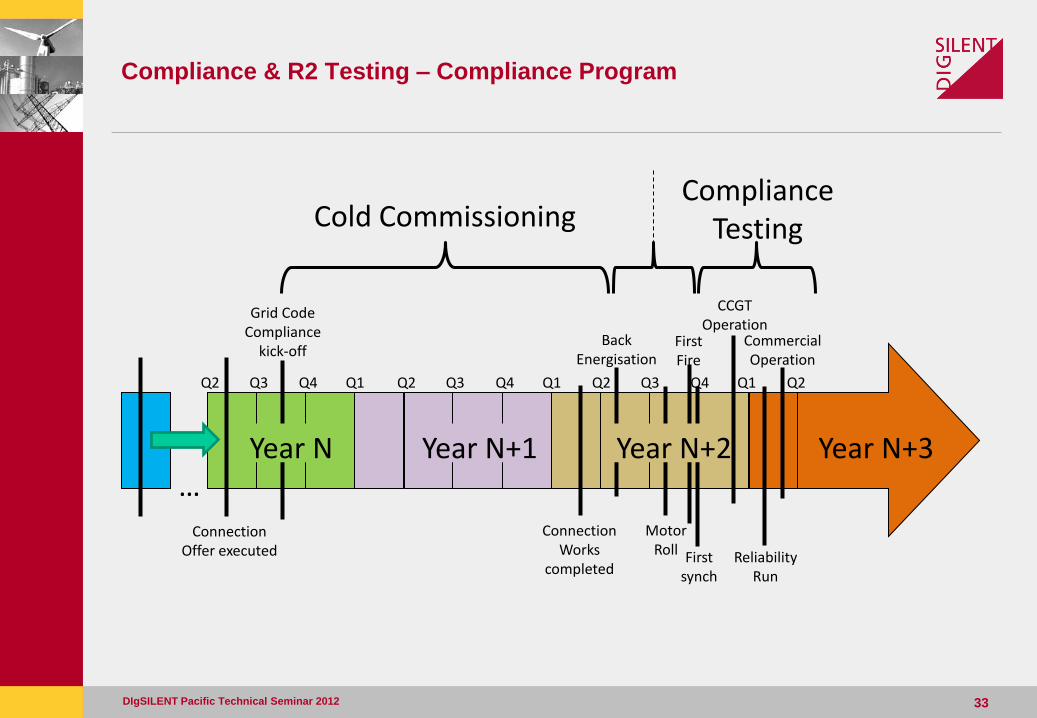
Connection Offer executed
Motor Roll
First Fire
First synch
Back Energisation
CCGT Operation
Cold Commissioning Compliance
Testing
Q1 Q2 Q3 Q4 Q1 Q2 Q3 Q4 Q1 Q2 Q3 Q4 Q2
Year N+2 Year N+3
Reliability Run
Commercial Operation
Year N+1
Grid Code Compliance
kick-off
Year N
Connection Works
completed
…
Compliance & R2 Testing – Compliance Program
• Compliance testing of an AVR and/or Governor for the Performance Standards they affect would occur every 4 years as recommended in the template
• R2 testing of the analysed sub-system must occur following any plant change, i.e. installation, modification, change in firmware or software version, etc.
• Test methodology includes:
– Unsynchronised and synchronised AVR step response tests
– Frequency response testing (droop testing)
– Partial and full load rejections
– AVR step response test of excitation limiters
– AVR and PSS transfer function measurements over required frequency range
DIgSILENT Pacific Technical Seminar 2012 34
Compliance & R2 Testing – cont.
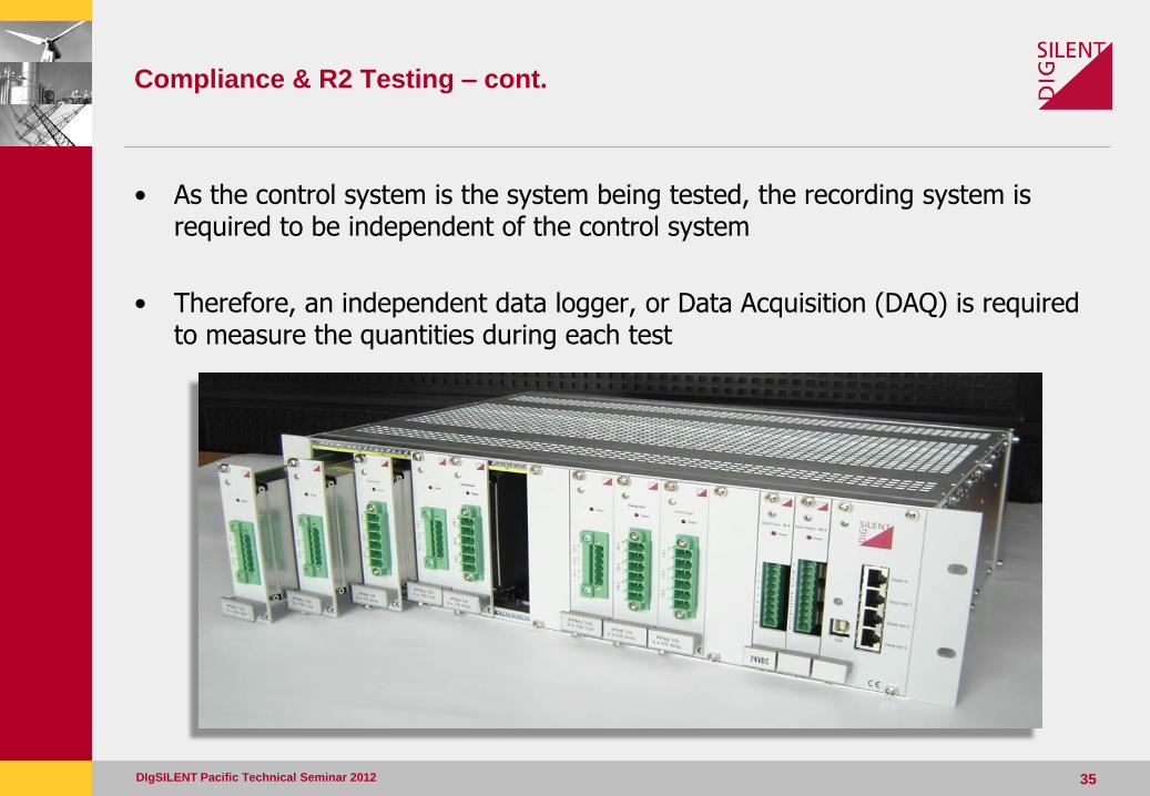
• As the control system is the system being tested, the recording system is required to be independent of the control system
• Therefore, an independent data logger, or Data Acquisition (DAQ) is required to measure the quantities during each test
DIgSILENT Pacific Technical Seminar 2012 35
Compliance & R2 Testing – Data Acquisition
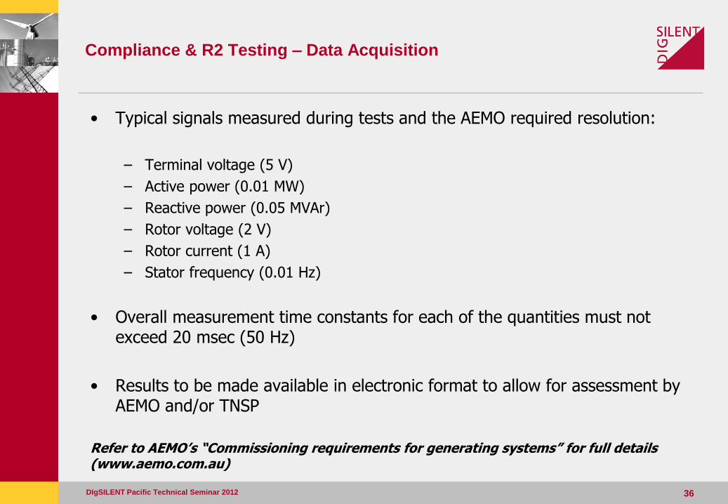
• Typical signals measured during tests and the AEMO required resolution:
– Terminal voltage (5 V)
– Active power (0.01 MW)
– Reactive power (0.05 MVAr)
– Rotor voltage (2 V)
– Rotor current (1 A)
– Stator frequency (0.01 Hz)
• Overall measurement time constants for each of the quantities must not exceed 20 msec (50 Hz)
• Results to be made available in electronic format to allow for assessment by AEMO and/or TNSP
Refer to AEMO’s “Commissioning requirements for generating systems” for full details (www.aemo.com.au)
DIgSILENT Pacific Technical Seminar 2012 36
Compliance & R2 Testing – Process
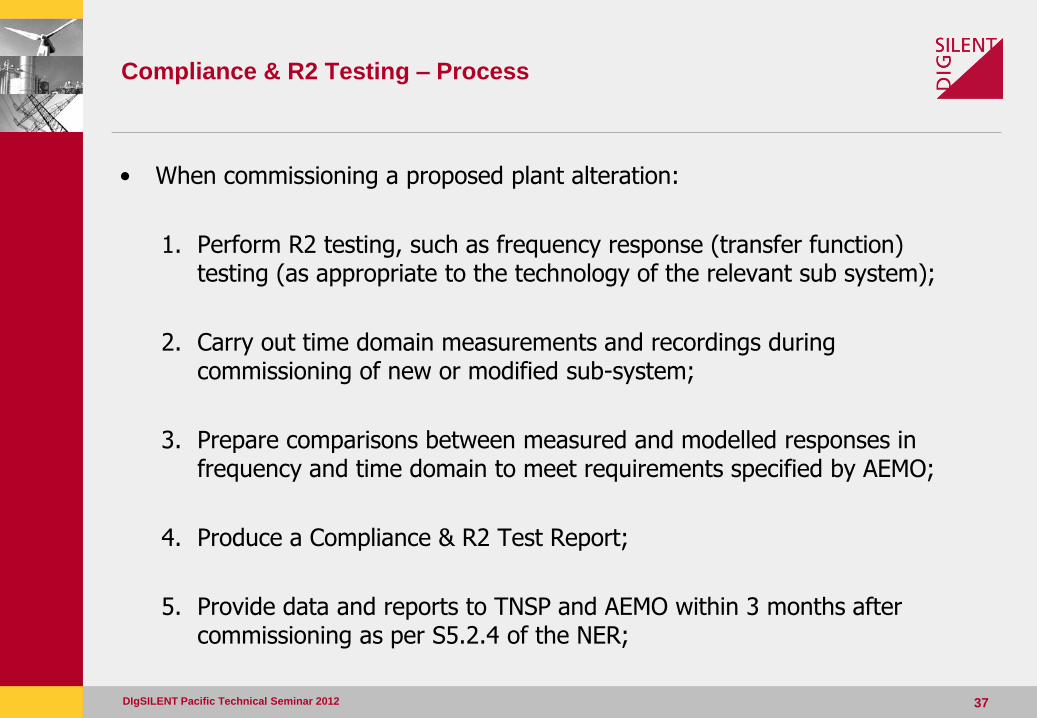
• When commissioning a proposed plant alteration:
1. Perform R2 testing, such as frequency response (transfer function) testing (as appropriate to the technology of the relevant sub system);
2. Carry out time domain measurements and recordings during commissioning of new or modified sub-system;
3. Prepare comparisons between measured and modelled responses in frequency and time domain to meet requirements specified by AEMO;
4. Produce a Compliance & R2 Test Report;
5. Provide data and reports to TNSP and AEMO within 3 months after commissioning as per S5.2.4 of the NER;
DIgSILENT Pacific Technical Seminar 2012 37
Compliance & R2 Testing – Accuracy Requirements
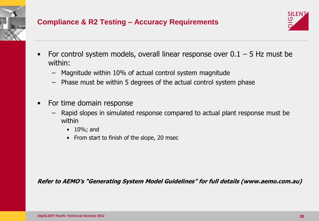
• For control system models, overall linear response over 0.1 – 5 Hz must be within:
– Magnitude within 10% of actual control system magnitude
– Phase must be within 5 degrees of the actual control system phase
• For time domain response
– Rapid slopes in simulated response compared to actual plant response must be within
• 10%; and
• From start to finish of the slope, 20 msec
Refer to AEMO’s “Generating System Model Guidelines” for full details (www.aemo.com.au)
DIgSILENT Pacific Technical Seminar 2012 38
Compliance & R2 Testing – R2 Testing
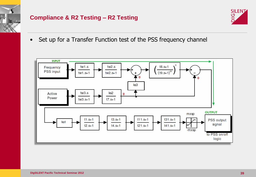
• Set up for a Transfer Function test of the PSS frequency channel
DIgSILENT Pacific Technical Seminar 2012 39
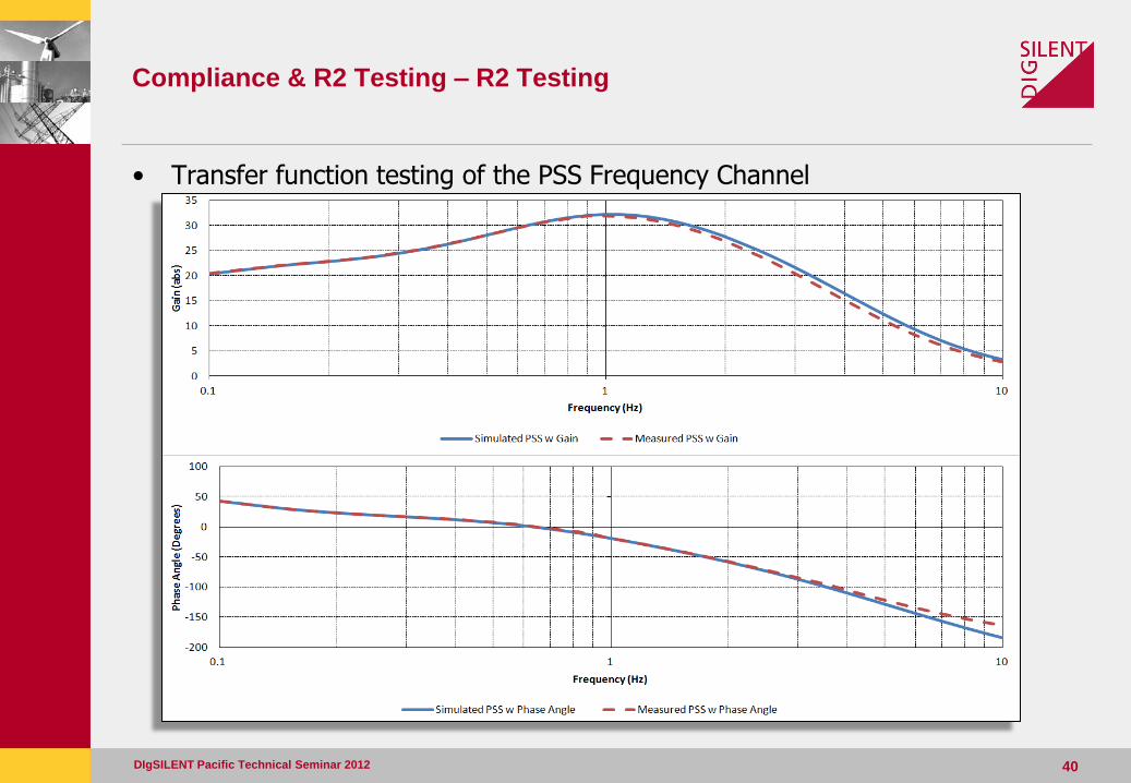
Compliance & R2 Testing – R2 Testing
• Transfer function testing of the PSS Frequency Channel
DIgSILENT Pacific Technical Seminar 2012 40
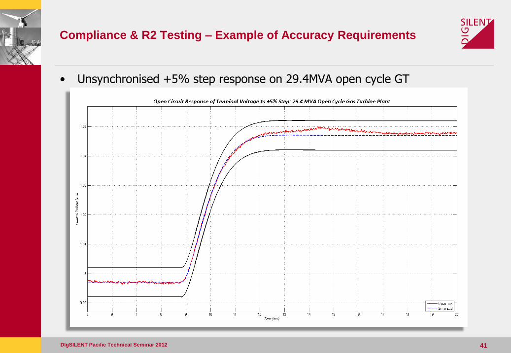
Compliance & R2 Testing – Example of Accuracy Requirements
DIgSILENT Pacific Technical Seminar 2012 41
• Unsynchronised +5% step response on 29.4MVA open cycle GT
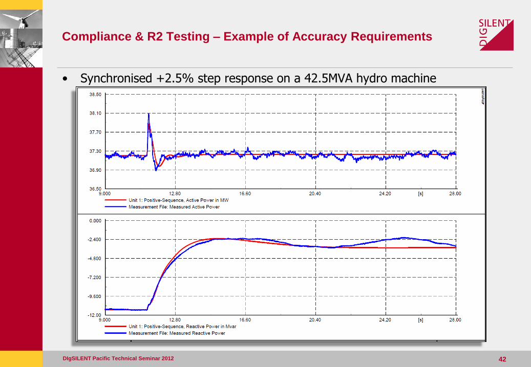
Compliance & R2 Testing – Example of Accuracy Requirements
DIgSILENT Pacific Technical Seminar 2012 42
• Synchronised +2.5% step response on a 42.5MVA hydro machine
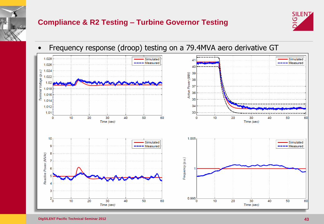
Compliance & R2 Testing – Turbine Governor Testing
DIgSILENT Pacific Technical Seminar 2012 43
• Frequency response (droop) testing on a 79.4MVA aero derivative GT
Compliance & R2 Testing – Turbine Governor Testing
DIgSILENT Pacific Technical Seminar 2012 44
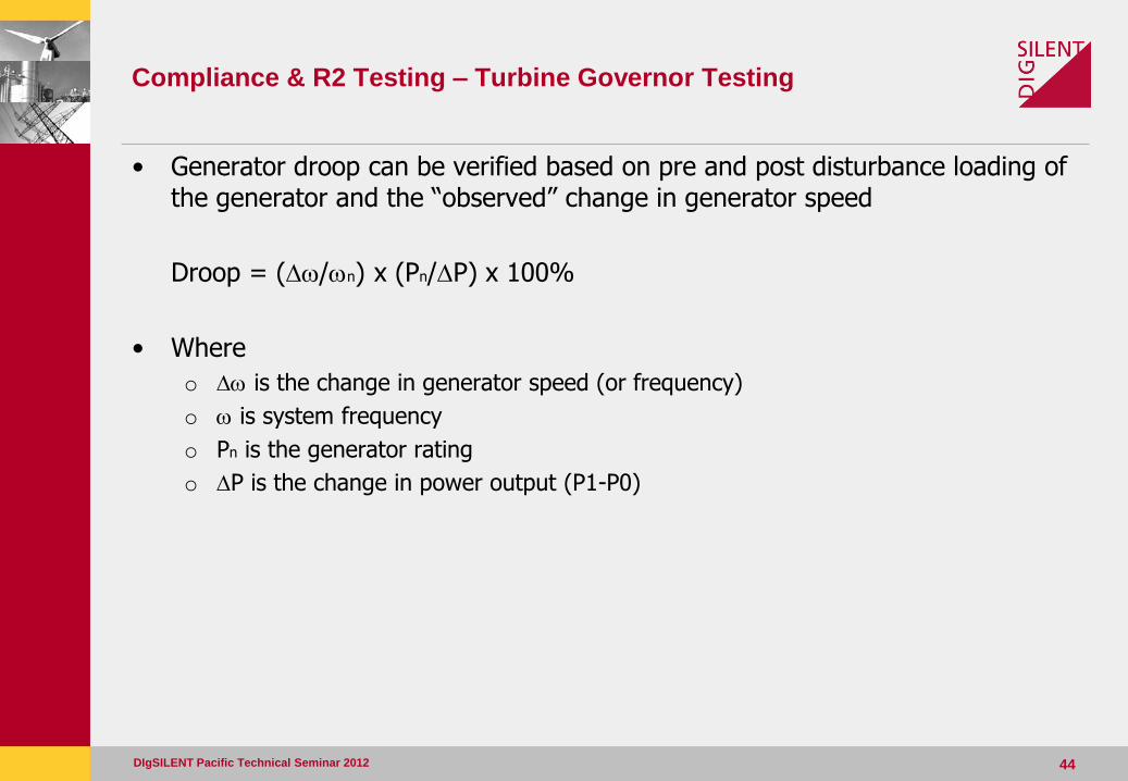
• Generator droop can be verified based on pre and post disturbance loading of the generator and the “observed” change in generator speed
Droop = (Dw/wn) x (Pn/DP) x 100%
• Where
o Dw is the change in generator speed (or frequency)
o w is system frequency
o Pn is the generator rating
o DP is the change in power output (P1-P0)
Compliance & R2 Testing – Turbine Governor Testing
DIgSILENT Pacific Technical Seminar 2012 45
• Other turbine governor tests would be defined by the type of turbine (i.e. hydro, gas, steam) but would produce a similar outcome
• Other testing would include verification of:
– Ramp rates
– Dead bands
– Load Limiters (such as Exhaust Gas Temperature limiter)
– Fuel valve or guide vane characteristics
– Steam flow demand
– Stability
Compliance & R2 Testing – Turbine Governor Testing
DIgSILENT Pacific Technical Seminar 2012 46
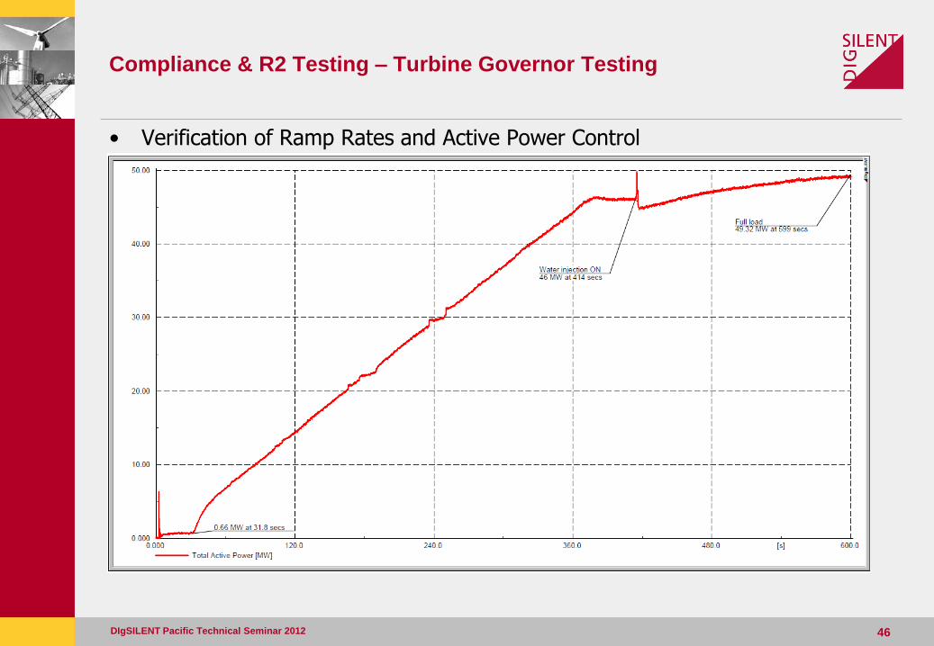
• Verification of Ramp Rates and Active Power Control
Compliance & R2 Testing – Synchronous Machine
• For new connections, the R1 data for the synchronous machine parameters will also need to be verified as R2 via on site testing.
– This will also occur if there are plant modifications to the synchronous machine (re-winding, new rotor, etc);
• The following tests will assist in the validation of the synchronous machine parameters:
– Open- and short-circuit characteristic
– Partial load rejections with AVR in constant current mode
• Assists with calculation of d- and q-axis parameters
– Partial load rejection with AVR in AUTO
• Assists with calculation of generator inertia
– Steady state vee curve measurements
– Standstill Frequency Response (SSFR) as per IEEE Standard 115-1995
DIgSILENT Pacific Technical Seminar 2012 47
Compliance & R2 Testing – Synchronous Machine
DIgSILENT Pacific Technical Seminar 2012 48
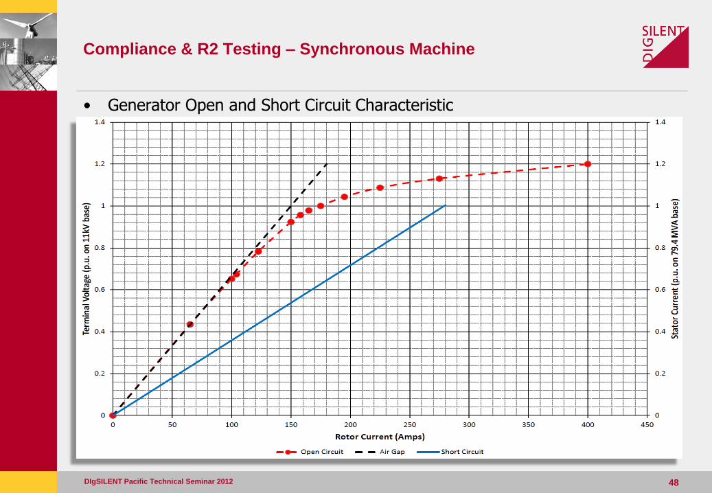
• Generator Open and Short Circuit Characteristic
Compliance & R2 Testing – Synchronous Machine
DIgSILENT Pacific Technical Seminar 2012 49
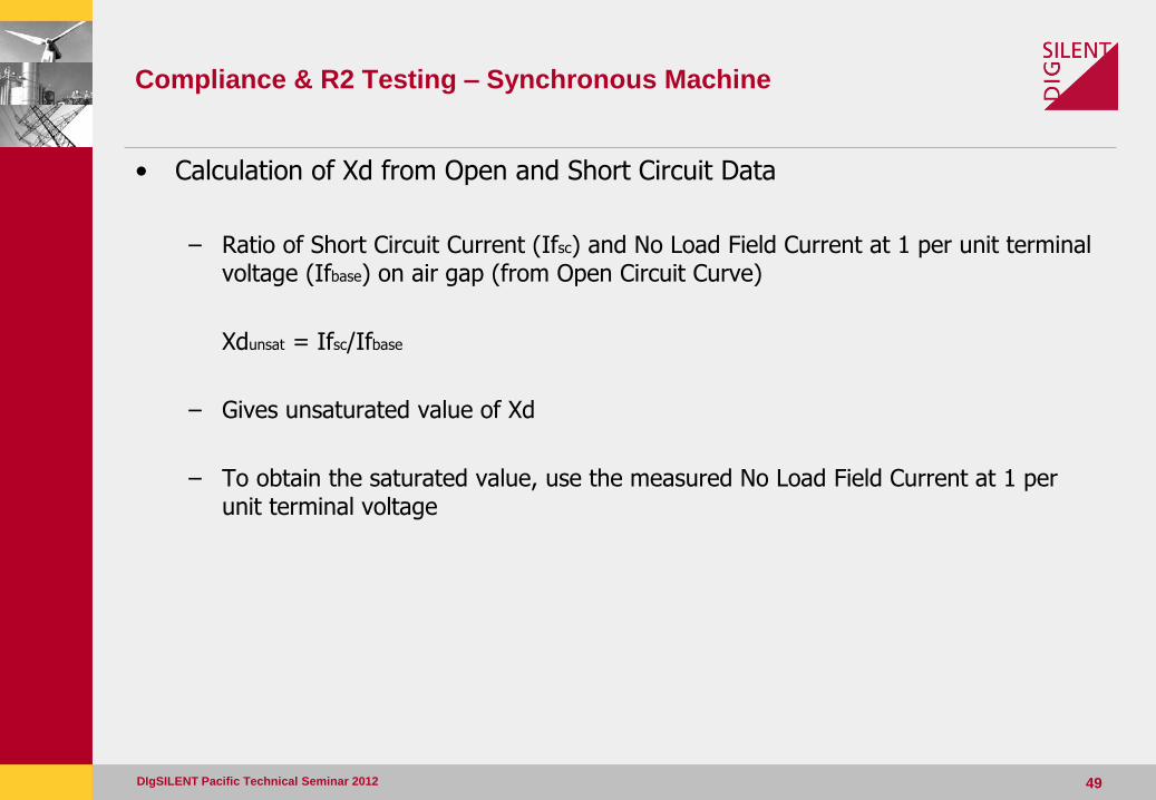
• Calculation of Xd from Open and Short Circuit Data
– Ratio of Short Circuit Current (Ifsc) and No Load Field Current at 1 per unit terminal voltage (Ifbase) on air gap (from Open Circuit Curve)
Xdunsat = Ifsc/Ifbase
– Gives unsaturated value of Xd
– To obtain the saturated value, use the measured No Load Field Current at 1 per unit terminal voltage
Compliance & R2 Testing – Synchronous Machine
DIgSILENT Pacific Technical Seminar 2012 50
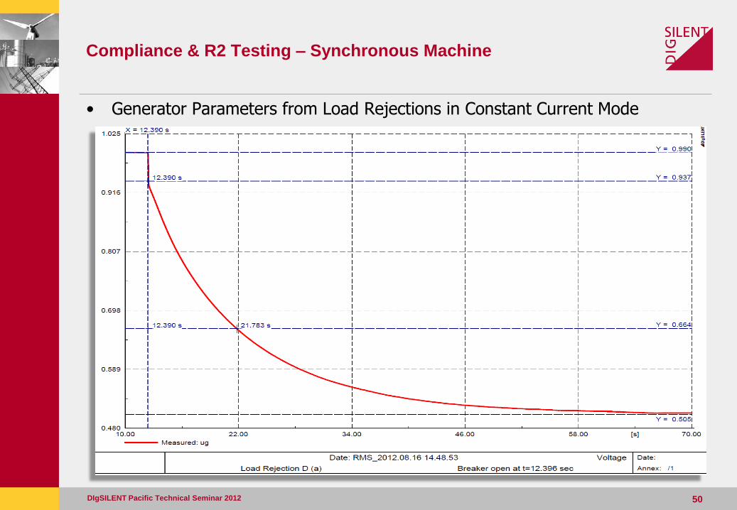
• Generator Parameters from Load Rejections in Constant Current Mode
Compliance & R2 Testing – Synchronous Machine
DIgSILENT Pacific Technical Seminar 2012 51
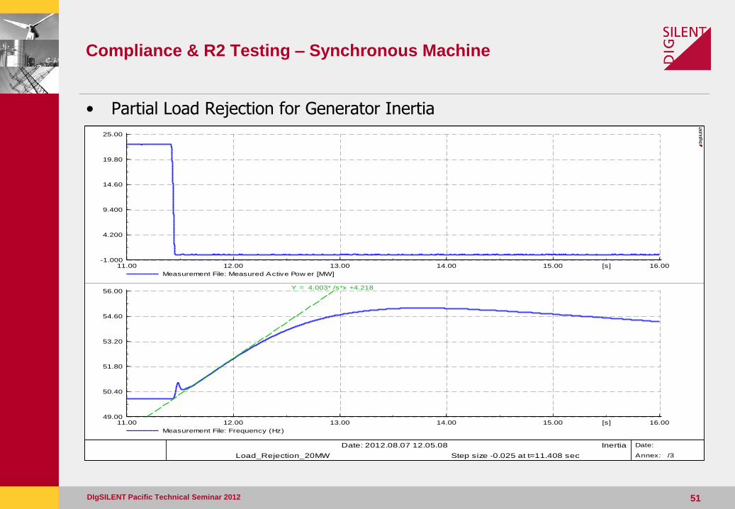
• Partial Load Rejection for Generator Inertia
16.0015.0014.0013.0012.0011.00 [s]
25.00
19.80
14.60
9.400
4.200
-1.000
Measurement File: Measured Active Pow er [MW]
16.0015.0014.0013.0012.0011.00 [s]
56.00
54.60
53.20
51.80
50.40
49.00
Measurement File: Frequency (Hz)
Y = 4.003* /s*x +4.218
Date: 2012.08.07 12.05.08 Inertia
Load_Rejection_20MW Step size -0.025 at t=11.408 sec
Date:
Annex: /3
DIg
SIL
EN
T
Compliance & R2 Testing – Synchronous Machine
DIgSILENT Pacific Technical Seminar 2012 52
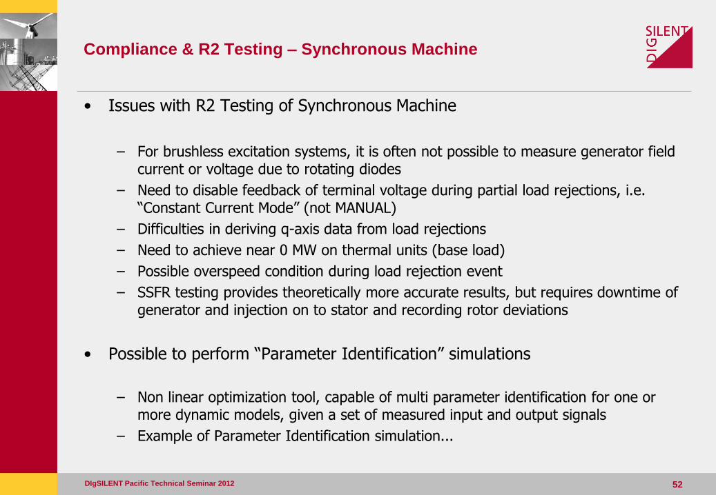
• Issues with R2 Testing of Synchronous Machine
– For brushless excitation systems, it is often not possible to measure generator field current or voltage due to rotating diodes
– Need to disable feedback of terminal voltage during partial load rejections, i.e. “Constant Current Mode” (not MANUAL)
– Difficulties in deriving q-axis data from load rejections
– Need to achieve near 0 MW on thermal units (base load)
– Possible overspeed condition during load rejection event
– SSFR testing provides theoretically more accurate results, but requires downtime of generator and injection on to stator and recording rotor deviations
• Possible to perform “Parameter Identification” simulations
– Non linear optimization tool, capable of multi parameter identification for one or more dynamic models, given a set of measured input and output signals
– Example of Parameter Identification simulation...
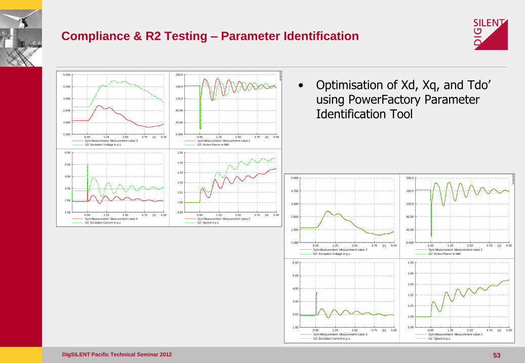
Compliance & R2 Testing – Parameter Identification
DIgSILENT Pacific Technical Seminar 2012 53
5.003.752.501.250.00 [s]
200.0
160.0
120.0
80.00
40.00
0.000
Sym Measurement: Measurement value 2
G2: Active Pow er in MW
5.003.752.501.250.00 [s]
5.000
4.200
3.400
2.600
1.800
1.000
Sym Measurement: Measurement value 3
G2: Excitation Voltage in p.u.
5.003.752.501.250.00 [s]
6.00
5.00
4.00
3.00
2.00
1.00
Sym Measurement: Measurement value 4
G2: Excitation Current in p.u.
5.003.752.501.250.00 [s]
1.05
1.04
1.03
1.02
1.01
1.00
0.99
Sym Measurement: Measurement value 5
G2: Speed in p.u.
DIg
SIL
EN
T
5.003.752.501.250.00 [s]
200.0
160.0
120.0
80.00
40.00
0.000
Sym Measurement: Measurement value 2
G2: Active Pow er in MW
5.003.752.501.250.00 [s]
5.000
4.200
3.400
2.600
1.800
1.000
Sym Measurement: Measurement value 3
G2: Excitation Voltage in p.u.
5.003.752.501.250.00 [s]
6.00
5.00
4.00
3.00
2.00
1.00
Sym Measurement: Measurement value 4
G2: Excitation Current in p.u.
5.003.752.501.250.00 [s]
1.05
1.04
1.03
1.02
1.01
1.00
0.99
Sym Measurement: Measurement value 5
G2: Speed in p.u.
DIg
SIL
EN
T
• Optimisation of Xd, Xq, and Tdo’ using PowerFactory Parameter Identification Tool
Thank You!
DIgSILENT Pacific Technical Seminar 2012 54