Embed Size (px)
Citation preview
www.afielektrik.comL 01
Electrical Group
EGS
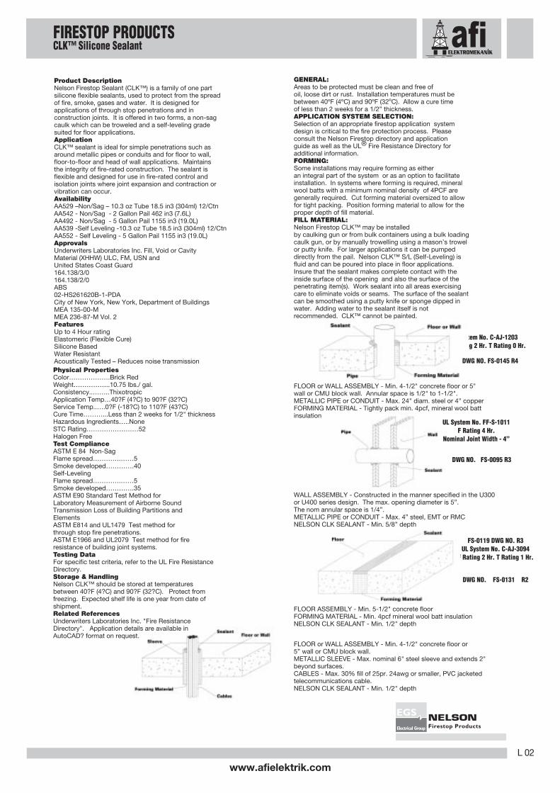
Product DescriptionNelson Fire Brick is a soft, pliable, intumescent materialthat is ideal for applications where the Firestopapplication may be required to be re-penetrated. Uponthe event of a fire, the brick material expands within theopening, forming a solid char that prevents throughpenetration of the fire.
ApplicationNelson Fire Brick is an economical, durable, laborsaving firestop material for cable or cable traypenetrations. Nelson Fire Brick should be installedinto a clean opening free of grease, dirt or looseparticles. For general application guidelines, tightlypack bricks into and around the penetrating item(s)within the annular space filling all voids. Install brickcentered within opening. Brick may be cut asnecessary to provide a tight fit between opening andpenetrating item. Actual installation should be inaccordance with the appropriate Nelson applicationsystem drawing or applicable system in the UL FireResistance Directory.
AvailabilityAA0834 – 2” x 5” x 8” Brick, 1.48lb. (670 grams)Packaged 6 / Carton
ApprovalsUnderwriters Laboratories Inc., Fill, Void or CavityMaterial (XHHW) and (XHHW7)
Features• Up to 2-Hour Ratings• Easily Installed• Non-Shrinking• Non-Toxic• Easily Re-penetrable• Excellent Shelf Life
Physical Properties• Color……………….Charcoal Gray• Weight……………..1.48 lbs.• Dimensions……….. 2” x 5” x 8”• Intumescent activation temp. >300°F• Asbestos Filler ……None
Test Compliance• ASTM E-814 and UL1479, Test method forthrough stop fire penetrations.
Testing DataFor specific test criteria, refer to the UL FireResistance Directory.
Storage & HandlingNelson Fire Brick should be stored in dry, coveredlocations. There is no indication of shelf life limitations.
Related ReferencesUnderwriters Laboratories Inc. "Fire ResistanceDirectory". Application details are available inAutoCAD. format on request.
GENERAL: Areas to be protected must be clean and free ofoil, loose dirt or rust.APPLICATION SYSTEM SELECTION: Selection of anappropriate firestop application system design is critical to thefire protection process. Please consult the Nelson Firestopdirectory and application guide as well as the UL. FireResistance Directory for additional information.FILL MATERIAL: Prior to installation of the Fire Bricks, min.3/8” thickness of putty forced into interstices of cables andbetween cables and cable tray within full depth of the studcavity. After installation of the Fire Bricks, min. 3/8” additionalputty applied between the interstices of cables, betweencables and cable tray, between the Fire Bricks and cables andbetween cable tray and Fire Brick on both surfaces of the wallassembly. At point of contact location between cable tray andwall, min. 3/8” thickness of putty applied at the cable tray/wallinterface on both surfaces of the wall.FIRE BRICK: For walls incorporating max. 3-1/2” steel studs,fire bricks installed with 5” dimension projecting through andcentered in opening. For walls constructed of larger than 3-1/2” steel studs Fire Brick installed with long dimensionpassing through and centered in opening. For reinforcedconcrete and solid filled concrete block wall assemblies, blocksinstalled centered within depth of opening with the longdimension placed horizontally. For HOLLOW-CORE blockwalls, Fire Brick installed with long dimension passing throughthe opening from surface to surface. Fire Bricks to completelyfill the opening.
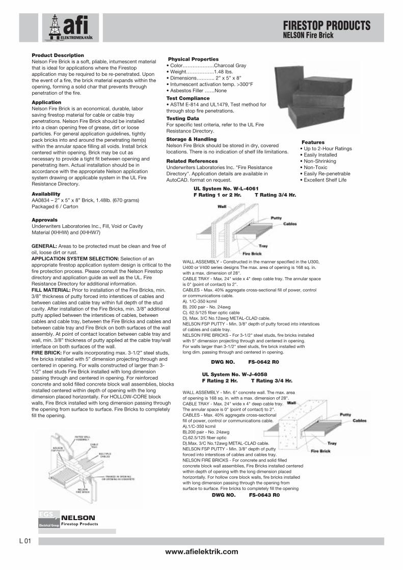
WALL ASSEMBLY - Constructed in the manner specified in the U300,U400 or V400 series designs The max. area of opening is 168 sq. in.with a max. dimension of 28".CABLE TRAY - Max. 24" wide x 4" deep cable tray. The annular spaceis 0" (point of contact) to 2".CABLES - Max. 40% aggregate cross-sectional fill of power, controlor communications cable.A). 1/C-350 kcmilB). 200 pair - No. 24awgC). 62.5/125 fiber optic cableD). Max. 3/C No.12awg METAL-CLAD cable.NELSON FSP PUTTY - Min. 3/8" depth of putty forced into intersticesof cables and cable tray.NELSON FIRE BRICKS - For 3-1/2" steel studs, fire bricks installedwith 5" dimension projecting through and centered in opening.For walls larger than 3-1/2" steel studs, fire brick installed withlong dim. passing through and centered in opening.
DWG NO. FS-0642 R0
UL System No. W-L-4061F Rating 1 or 2 Hr. T Rating 3/4 Hr.
UL System No. W-J-4058F Rating 2 Hr. T Rating 3/4 Hr.
WALL ASSEMBLY - Min. 6" concrete wall. The max. areaof opening is 168 sq. in. with a max. dimension of 28".CABLE TRAY - Max. 24" wide x 4" deep cable tray.The annular space is 0" (point of contact) to 2".CABLES - Max. 40% aggregate cross-sectionalfill of power, control or communications cable.A).1/C-350 kcmilB).200 pair - No. 24awgC).62.5/125 fiber opticD).Max. 3/C No.12awg METAL-CLAD cable.NELSON FSP PUTTY - Min. 3/8" depth of puttyforced into interstices of cables and cables tray.NELSON FIRE BRICKS - For concrete and solid filledconcrete block wall assemblies, Fire Bricks installed centeredwithin depth of opening with the long dimension placedhorizontally. For hollow core block walls, fire bricks installedwith long dimension passing through the opening fromsurface to surface. Fire bricks to completely fill the opening
DWG NO. FS-0643 R0
FIRESTOP PRODUCTSNELSON Fire Brick
L 02
www.afielektrik.com
Electrical Group
EGS
Product DescriptionNelson Firestop Sealant (CLK™) is a family of one partsilicone flexible sealants, used to protect from the spreadof fire, smoke, gases and water. It is designed forapplications of through stop penetrations and inconstruction joints. It is offered in two forms, a non-sagcaulk which can be troweled and a self-leveling gradesuited for floor applications.ApplicationCLK™ sealant is ideal for simple penetrations such asaround metallic pipes or conduits and for floor to wall,floor-to-floor and head of wall applications. Maintainsthe integrity of fire-rated construction. The sealant isflexible and designed for use in fire-rated control andisolation joints where joint expansion and contraction orvibration can occur.AvailabilityAA529 –Non/Sag – 10.3 oz Tube 18.5 in3 (304ml) 12/CtnAA542 - Non/Sag - 2 Gallon Pail 462 in3 (7.6L)AA492 - Non/Sag - 5 Gallon Pail 1155 in3 (19.0L)AA539 -Self Leveling -10.3 oz Tube 18.5 in3 (304ml) 12/CtnAA552 - Self Leveling - 5 Gallon Pail 1155 in3 (19.0L)ApprovalsUnderwriters Laboratories Inc. Fill, Void or CavityMaterial (XHHW) ULC, FM, USN andUnited States Coast Guard164.138/3/0164.138/2/0ABS02-HS261620B-1-PDACity of New York, New York, Department of BuildingsMEA 135-00-MMEA 236-87-M Vol. 2FeaturesUp to 4 Hour ratingElastomeric (Flexible Cure)Silicone BasedWater ResistantAcoustically Tested – Reduces noise transmission
GENERAL:Areas to be protected must be clean and free ofoil, loose dirt or rust. Installation temperatures must bebetween 40ºF (4ºC) and 90ºF (32ºC). Allow a cure timeof less than 2 weeks for a 1/2” thickness.APPLICATION SYSTEM SELECTION:Selection of an appropriate firestop application systemdesign is critical to the fire protection process. Pleaseconsult the Nelson Firestop directory and applicationguide as well as the UL® Fire Resistance Directory foradditional information.FORMING:Some installations may require forming as eitheran integral part of the system or as an option to facilitateinstallation. In systems where forming is required, mineralwool batts with a minimum nominal density of 4PCF aregenerally required. Cut forming material oversized to allowfor tight packing. Position forming material to allow for theproper depth of fill material.FILL MATERIAL:Nelson Firestop CLK™ may be installedby caulking gun or from bulk containers using a bulk loadingcaulk gun, or by manually trowelling using a mason’s trowelor putty knife. For larger applications it can be pumpeddirectly from the pail. Nelson CLK™ S/L (Self-Leveling) isfluid and can be poured into place in floor applications.Insure that the sealant makes complete contact with theinside surface of the opening and also the surface of thepenetrating item(s). Work sealant into all areas exercisingcare to eliminate voids or seams. The surface of the sealantcan be smoothed using a putty knife or sponge dipped inwater. Adding water to the sealant itself is notrecommended. CLK™ cannot be painted.
WALL ASSEMBLY - Constructed in the manner specified in the U300or U400 series design. The max. opening diameter is 5”.The nom annular space is 1/4”.METALLIC PIPE or CONDUIT - Max. 4” steel, EMT or RMCNELSON CLK SEALANT - Min. 5/8” depth
UL System No. C-AJ-1203F Rating 2 Hr. T Rating 0 Hr.
Physical PropertiesColor……………….Brick RedWeight……………..10.75 lbs./ gal.Consistency..……..ThixotropicApplication Temp…40?F (4?C) to 90?F (32?C)Service Temp..….0?F (-18?C) to 110?F (43?C)Cure Time………...Less than 2 weeks for 1/2" thicknessHazardous Ingredients…..NoneSTC Rating……………………52Halogen FreeTest ComplianceASTM E 84 Non-SagFlame spread………….……5Smoke developed………….40Self-LevelingFlame spread………….……5Smoke developed………….35ASTM E90 Standard Test Method forLaboratory Measurement of Airborne SoundTransmission Loss of Building Partitions andElementsASTM E814 and UL1479 Test method forthrough stop fire penetrations.ASTM E1966 and UL2079 Test method for fireresistance of building joint systems.Testing DataFor specific test criteria, refer to the UL Fire ResistanceDirectory.Storage & HandlingNelson CLK™ should be stored at temperaturesbetween 40?F (4?C) and 90?F (32?C). Protect fromfreezing. Expected shelf life is one year from date ofshipment.Related ReferencesUnderwriters Laboratories Inc. "Fire ResistanceDirectory". Application details are available inAutoCAD? format on request.
FLOOR or WALL ASSEMBLY - Min. 4-1/2" concrete floor or 5"wall or CMU block wall. Annular space is 1/2" to 1-1/2".METALLIC PIPE or CONDUIT - Max. 24" diam. steel or 4" copperFORMING MATERIAL - Tightly pack min. 4pcf, mineral wool battinsulation
DWG NO. FS-0145 R4
UL System No. FF-S-1011F Rating 4 Hr.
Nominal Joint Width - 4”
DWG NO. FS-0095 R3
FS-0119 DWG NO. R3UL System No. C-AJ-3094
F Rating 2 Hr. T Rating 1 Hr.
FLOOR ASSEMBLY - Min. 5-1/2" concrete floorFORMING MATERIAL - Min. 4pcf mineral wool batt insulationNELSON CLK SEALANT - Min. 1/2" depth
DWG NO. FS-0131 R2
FLOOR or WALL ASSEMBLY - Min. 4-1/2" concrete floor or5” wall or CMU block wall.METALLIC SLEEVE - Max. nominal 6" steel sleeve and extends 2"beyond surfaces.CABLES - Max. 30% fill of 25pr. 24awg or smaller, PVC jacketedtelecommunications cable.NELSON CLK SEALANT - Min. 1/2" depth
FIRESTOP PRODUCTSCLK™ Silicone Sealant

www.afielektrik.comL 03
Electrical Group
EGS
FLOOR or WALL ASSEMBLY - Min. 4-1/2" concrete floor orwall, or CMU block wall. The max. size of opening is 40" x 48".METALLIC PIPE or CONDUIT - Max. 10" steel, 6" RMC, 4" EMTor copper pipe. Annular space is 1" to 37" and betweenpipes is 2" to 40".NELSON CMP COMPOUND - Min. 4-1/2" depth
Product DescriptionNelson Compound (CMP™) is a cementitious material that is mixed with water.It is similar in appearance to mortar and can be troweled to a smooth finishthat provides a weather resistant, non-shrinking fire-rated seal.ApplicationCMP™ has been tested for a wide range of penetrants including metallic pipes,cables, cable trays, as well as combustible penetrants such as insulated pipes.It is ideally suited for medium to large openings filled with or without penetrants.AvailabilityAA0476 - 44 lb. Bag - 1000 cu. in. (16.4L)ApprovalsUnderwriters Laboratories Inc., Fill, Void or Cavity Material (XHHW) and(XHHW7), FMCity of New York, New York, Department of Buildings• MEA 236-87-M Vol. 2Features• Up to 4-Hour Ratings• Economical• Non-Shrinking• Paintable• Water Resistant• Non-Toxic• Excellent Shelf Life• Ideal for Large Openings• Acoustically Tested – Reduces noise transmissionPhysical Properties• Color……………….Red• Weight……………..44 lbs. per Bag• Yield per bag………1000 cu. in.• Application Temp…40°F (4°C) and above• Set Up Time……….4 hours (approx)• Cure Time………….4 weeks (approx)• Hydrostatic Pressure..>30 psi (206kPa)• Mix Ratio - Water to CMP compound1:4.0………420 psi (2895.8 kPa)1:3.5………395 psi (2723.5 kPa)1:3.0………300 psi (2068.4 kPa)1:2.5………240 psi (1654.7 kPa)Test Compliance• ASTM E119 and UL263, Fire Tests of Building Construction and Materials• ASTM E814 and UL1479, Test method for through stop fire penetrations.Testing DataFor specific test criteria, refer to the UL Fire Resistance Directory.Storage & HandlingNelson CMP™ should be stored in dry, covered locations. There is noindication of shelf life limitations.LimitationsNelson CMP™ is not a load bearing material. If the area is subject topedestrian traffic, safety plates must be installed.Related ReferencesUnderwriters Laboratories Inc. "Fire Resistance Directory". Applicationdetails are available in AutoCAD. format on request.GENERAL: Areas to be protected must be clean and free of oil, loosedirt or rust. Installation temperatures must be 40ºF (4ºC) and above.Allow a cure time of 4 weeks.APPLICATION SYSTEM SELECTION: Selection of an appropriate firestopsystem design is critical to the fire protection process. Please consult theNelson Firestop directory and application guide as well as the UL. FireResistance Directory for additional information.FORMING: Some installations may require forming as either an integral partof the system or as an option to facilitate installation. In systems whereforming is required, plywood or foam insulation boards may be used. Insmaller openings, mineral fiber, backer rod or other suitable materials maybe used. Recess forming material to a depth which allows for theproper depth of fill material.FILL MATERIAL: Nelson Firestop CMP. may be mixed with water using astandard mortar mixer, plastering machine, or mixed by hand in smalleramounts. CMP™ Compound should be thoroughly mixed with water toachieve a uniform texture. Clean adjacent surfaces of opening prior toinstallation. For installation without forming, use 1:4 water/compound mixratio. For quicker installation with forming, use 1:2.5 water/compound ratio.Avoid extreme mix ratios. Material can be pumped, troweled or handpacked into the opening. Floor or wall penetrations with large open areasmay require some temporary forming. Nelson CMP™ sets up in about fourhours and cures completely in approximately four weeks. Actual installationshould be in accordance with the appropriate Nelson application systemdrawing.
UL System No. C-AJ-0043F Rating 3 Hr. T Rating 2 Hr.
FLOOR or WALL ASSEMBLY - Min. 4-1/2" concrete floor or wall,or CMU block wall. The max. size of the opening is 40" x 48".NELSON CMP COMPOUND - Install min. 4-1/2" depth
DWG NO. FS-0124 R2
UL System No. C-AJ-1040, 8007F Rating 2,3,4 Hr. T Rating 0 or 1/2 Hr.
DWG NO. FS-0125 R4
FLOOR or WALL ASSEMBLY - Min 3-1/4" concrete floor or wallor CMU block wall. The max. size of opening is 10" x 30".METALLIC PIPE or CONDUIT - Max. (5) pipes or conduits, max.6" steel or cast iron, RMC, max. 4" EMT or max. 2" copper pipe.Annular space is 3/4" to 4-3/4". Spacing between pipes or conduitsis 3/4" to 1-1/2".PIPE INSULATION (optional), Max. 1" thick FIBERGLASSor MINERAL WOOL. Annular space is 1-1/2" - 3-3/4".NELSON CMP COMPOUND - Min. 3-1/4" depth for 2 or 3 hrF- Rating or 7" depth for 4 hr F- Rating.
UL System No. C-AJ-1219F Rating 2 Hr. T Rating 0 Hr.
UL System No. C-AJ-8049F Rating 2 Hr. T Rating 0 Hr.
FLOOR or WALL ASSEMBLY - Min. 4-1/2" concrete floor or wall, orCMU block wall. The max. size of the opening is 40" X 48".The annular space is 1" to 12".METALLIC PIPE or CONDUITS - Max. (2) 10" steel, cast iron. Max.6" RMC, 4" copper or EMT. Annular space is 1" to 6-1/2" for pipesand 4" to 12" for trays.CABLES - Max. 30% fill of power, control, or communications cables.NELSON CMP COMPOUND - Min. 4-1/2" depth, flush with the top surfaceof the floor or both surfaces of the wall.
DWG NO. FS-0149 R2
FIRESTOP PRODUCTSCMP™ Firestop Compound
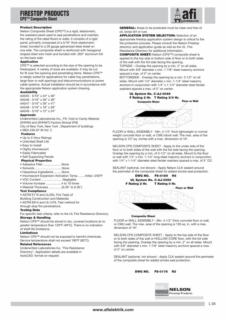
UL System No. C-AJ-0050F Rating 2 Hr. T Rating 0 Hr.
FLOOR or WALL ASSEMBLY - Min. 4-1/2" thick concrete floor or wall,or CMU wall. The max. area of the opening is 126 sq. in. with a max.dimension of 18".
NELSON CPS COMPOSITE SHEET - Apply to the top side of the flooror to both sides of the wall or HOLLOW-CORE floor, with the foil sidefacing the opening. Overlap the opening by a min. 2" on all sides. Mountwith 3/8" diameter x min. 1-7/8" steel masonry anchors spaced a max.of 5" on center.
SEALANT (optional, not shown) - Apply CLK sealant around the perimeterof the composite sheet for added smoke seal protection.
DWG NO. FS-0176 R3
FLOOR or WALL ASSEMBLY - Min. 4-1/2" thick lightweight or normalweight concrete floor or wall, or CMU block wall. The max. area of theopening is 127 sq. inches with a max. dimension of 18".
NELSON CPS COMPOSITE SHEET - Apply to the under side of thefloor or to both sides of the wall with the foil side facing the opening.Overlap the opening by a min. of 3-1/2" on all sides. Mount to the flooror wall with 1/4" x min. 1-1/4" long steel masonry anchors in conjunctionwith 1/4" x 1-1/4" diameter steel fender washers spaced a max. of 5" OC.
SEALANT (optional, not shown) - Apply Nelson CLK sealant aroundthe perimeter of the composite sheet for added smoke seal protection.
DWG NO. FS-0169 R4
L 04
www.afielektrik.com
Electrical Group
EGS
Product DescriptionNelson Composite Sheet (CPS™) is a rigid, elastomeric,fire resistant panel used to seal penetrations and maintainthe rating of fire rated floors or walls. It consists of a rigidpanel, primarily composed of a 5/16” thick elastomericsheet, bonded to a 28 gauge galvanized steel sheet onone side. The composite sheet is reinforced with hexagonalshaped steel wire mesh and bonded with .003" aluminum foilon the back side.ApplicationCPS™ is selected according to the size of the opening to befirestopped. A variety of sizes are available. It may be cutfor fit over the opening and penetrating items. Nelson CPS™is ideally suited for applications for cable tray penetrations,large floor or wall openings and telecommunications or powercable systems. Actual installation should be in accordance withthe appropriate Nelson application system drawing.AvailabilityAA545 - 5/16” x 24” x 36”AA546 - 5/16” x 36” x 36”AA547 - 5/16” x 36” x 41”AA548 - 5/16” x 16” x 28”AA549 - 5/16” x 12” x 24”ApprovalsUnderwriters Laboratories Inc., Fill, Void or Cavity Material(XHHW) and (XHHW7) Factory Mutual (FM)City of New York, New York , Department of buildings• MEA 236-87-M Vol. 2 Features• Up to 2-Hour Ratings• Unlimited Shelf Life• Easy to Install• Highly Intumescent• Easily Fabricated• Self Supporting Panels Physical Properties• Asbestos Filler ………………None• Solvents ……………………...None• Hazardous Ingredients ……..None• Intumescent Expansion Activation Temp……..Initial >250ºF• VOC Content …………………Negligible• Volume Increase …………....4 to 10 times• Material Thickness ………….(0.28" to 0.36")Test Compliance• ASTM E119 and UL263, Fire Tests ofBuilding Construction and Materials• ASTM E814 and UL1479, Test method forthrough stop fire penetrations.Testing DataFor specific test criteria, refer to the UL Fire Resistance Directory.Storage & HandlingNelson CPS™ should be stored in dry, covered locations at nogreater temperature than 120ºF (49ºC). There is no indicationof shelf life limitations.LimitationsNelson CPS™ should not be exposed to harmful chemicals.Service temperature shall not exceed 180ºF (82ºC).Related ReferencesUnderwriters Laboratories Inc. "Fire ResistanceDirectory". Application details are available inAutoCAD. format on request.
GENERAL: Areas to be protected must be clean and free ofoil, loose dirt or rust.APPLICATION SYSTEM SELECTION: Selection of anappropriate firestop application system design is critical to thefire protection process. Please consult the Nelson Firestopdirectory and application guide as well as the UL. FireResistance Directory for additional information.COMPOSITE SHEET: Nelson (CPS™) composite sheet isapplied to the top side or bottom side of floor or to both sidesof the wall with the foil side facing the opening.TOPSIDE – Overlap the opening by a min. 2” on all sides.Mount with 3/8” diameter x min. 1-7/8” steel masonry anchorsspaced a max. of 5” on center.BOTTOMSIDE - Overlap the opening by a min. 3-1/2” on allsides. Mount with 1/4” diameter x min. 1-1/4” steel masonryanchors in conjunction with 1/4” x 1-1/4” diameter steel fenderwashers spaced a max. of 5” on center.
UL System No. C-AJ-0049F Rating 2 Hr. T Rating 3/4 Hr.
FIRESTOP PRODUCTSCPS™ Composite Sheet
www.afielektrik.comL 05
Electrical Group
EGS
Product DescriptionNelson Firestop Elastomeric Sealant (ES1399™) is a cost effective,water based acrylic latex, endothermic, fire protective sealant. It isdesigned for applications of through firestop penetrations and inconstruction joints.ApplicationES1399™ sealant can be applied using a conventional caulk gun,bulk loader or by trowel. For larger applications it can be pumpeddirectly from the pail. ES1399™ is applicable for through firestoppenetrations and for floor to wall, floor-to-floor and head of wallapplications. It is flexible and is ideal for applications where jointexpansion and contraction can occur. Apply the required depthof sealant beginning on the edge of the opening (use over variousbacking materials as required). Insure that the sealant makes completecontact with the inside surface of the opening and also the surface ofthe penetrating item(s). On joints, the surfaces should be clean and freeof dust, dirt, oil, grease, loose material, rust or other substances. Applythe required thickness in the joint or over the insulation if required.AvailabilityAA0870 – Non/Sag-10.3 oz Tube 18.5 in3 (304ml) 12/Ctn.AA0874 - Non/Sag -20.2 oz Foil Pack 36.45 in3 (597 ml) 12/Ctn.AA0890 – Non/Sag - 30 oz Tube 54 in3 (883ml) 10/Ctn.AA0871 – Non/Sag – 5 Gallon Pail 1155 in3 (19.0L)ApprovalsUnderwriters Laboratories Inc.Fill, Void or Cavity Material (XHHW)City of New York, New York, Department of Buildings.• MEA 125-04-MFeatures• Up to 4-Hour ratings• Water-Based Acrylic Latex – Easy clean-up• Economical• Elastomeric (Flexible Cure)• Paintable• Water Resistant• Acoustically Tested – Reduces noise transmissionPhysical Properties• Color……………….Red• Weight……………..10.75 lbs. per gallon• Consistency...……..Thixotropic• Application Temp…40°F (4°C) to 90°F (32°C)• STC Rating………………52Test ComplianceFlame spread……………..0Smoke developed….……30• ASTM E90 Standard Test Method for Laboratory Measurement ofAirborne Sound Transmission Loss of Building Partitions and• ASTM E814 and UL1479 Test method for through stop fire penetrations.• ASTM E1399 Test method for cyclic movement and measuring min. and max. joint• ASTM E1966 and UL2079 Test method for fire resistance of building joint systems.Testing DataFor specific test criteria, refer to the UL Fire Resistance Directory.Storage & HandlingNelson ES1399™ should be stored at temperatures between 40°F (4°C) and90°F (32°C). Protect from freezing. Expected shelf life is one year from date ofRelated ReferencesUnderwriters Laboratories Inc. "Fire Resistance Directory". Application detailsare available inAutoCAD. format on request.GENERAL: Areas to be protected must be clean and free of oil, loose dirt or rust.Installation temperatures must be between 40oF (4oC) and 90oF (32oC). Allow acure time of less than 2 weeks for a 1/2” thickness.APPLICATION SYSTEM SELECTION: Selection of an appropriate firestopapplication system design is critical to the fire protection process. Pleaseconsult the Nelson Firestop directory and application guide as well as the UL.Fire Resistance Directory for additional information.FORMING: Some installations may require forming as either an integral part of thesystem or as an option to facilitate installation. In systems where forming is required,mineral wool batts with a minimum nominal density of 4PCF are generally required.Cut forming material oversized to allow for tight packing. Position forming materialto allow for the proper depth of fill material.FILL MATERIAL: Nelson Firestop ES1399™ may be installed by caulking gun or frombulk containers using a bulk loading caulk gun, or by manually trowelling using amason’s trowel or putty knife. For larger applications it can be pumped directly fromthe pail. Insure that the sealant makes complete contact with the inside surfaceof the opening and also the surface of the penetrating item(s). Work sealant intoall areas exercising care to eliminate voids or seams. The surface of the sealantcan be smoothed using a putty knife or sponge dipped in water. Adding water tothe sealant itself is not recommended. ES1399™ can be painted.
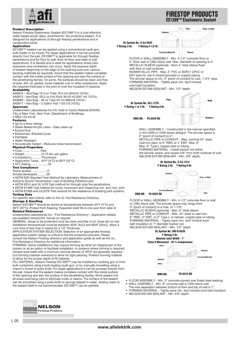
FLOOR or WALL ASSEMBLY - Min. 4-1/2" concrete floor or5" thick wall or CMU block wall. Max. diameter of opening is 4".METALLIC SLEEVE (optional) - Nom 4" steel sleeve flushwith floor or wall surfaces.NONMETALLIC PIPE - Max. 2" PVC or SDR17 CPVC orENT pipe for use in closed (process or supply) pipingThe annular space is min. 0" (point of contact) to max. 1-3/4" pipe.FORMING MATERIAL - Tightly pack min. 4pcf mineralwool batt insulationNELSON ES1399 SEALANT - Min. 1/2" depth
UL System No. C-AJ-2525F Rating 3 Hr. T Rating 2-1/2 Hr.
WALL ASSEMBLY - Constructed in the manner specifiedin the U300 or U400 series designs. The annular space is0" (point of contact) to 2".METALLIC PIPE or CONDUIT - Max. nominal 24" steel,cast iron pipe, or 6" RMC or 4" EMT. Max. 6"Max. 6" Type L copper pipe or tubing.FORMING MATERIAL - Install backer rod withinthe annular space, and recess 5/8" from both surfaces of wall.NELSON ES1399 SEALANT - Min. 5/8" depth.
UL System No. W-L-1276F Rating 1 or 2 Hr. T Rating 0 Hr.
• FLOOR ASSEMBLY - Min. 3” concrete poured over fluted steel decking.• WALL ASSEMBLY - Min. 8” concrete wall or CMU block wall.
The max seperation between bottom of floor and top of wall is 1”.• FORMING MATERIAL - Tightly pack min. 4pcf mineral wool batt insulation• NELSON ES1399 SEALANT - Min. 5/8” depth.
UL System No. C-AJ-1414F Rating 3 Hr. T Rating 0 Hr.
DWG NO. FS-0348 R0
UL System No. HW-D-0230F Rating 2 Hr.
Nominal Joint Width - 1"Class II Movement - 25 % Compression
DWG NO. FS-0352 R0
FLOOR or WALL ASSEMBLY - Min. 4-1/2” concrete floor or wall,or CMU block wall. The annular space may range from0” (point of contact) to a max. of 1-7/8”.METALLIC SLEEVE (optional) - Max. 8” steel sleeveMETALLIC PIPE or CONDUIT - Max. 24” steel or cast iron,6” RMC, 4” EMT, or 6” Type L or heavier, copper pipe or tubing.FORMING MATERIAL - Tightly pack min. 4pcf mineral woolbatt insulation or 1” diameter backer rodNELSON ES1399 SEALANT - MIn. 1/2” depth.
DWG NO. FS-0375 RO
FIRESTOP PRODUCTSES1399™ Elastomeric Sealant

L 06
www.afielektrik.com
Electrical Group
EGS
Product DescriptionNelson Firestop Joint Coating (FSC3™) is a water based acrylic latex, elastomeric,fire protective coating for use on construction joints. It is designed for labor savingspray applications onto construction joints and perimeter joint systems(curtain wall assemblies).ApplicationFSC3™ coating is spray, brush or trowelled applied over a min. 4” depth of mineralwool insulation packed within the joint width. FSC3™ is specifically for applicationsin construction joints, wall to wall, floor to wall, floor to floor, head of wall andperimeter joint curtain wall applications where thermal expansion and contractionof joints may be encountered. Actual installation may vary according to the type ofjoint to be protected. Joint surfaces should be clean and free of dust, dirt, oil,grease, loose material, rust or other substances. A 1/8” wet thickness is appliedover the insulation and overlaps the joint surfaces by a minimum 1/2”. Productcures to a nominal 1/16" dry thickness.AvailabilityAA0868 - 5 Gallon Pail (19.0L) – 1,155 cu. in.Sprayer RequirementsUse a mid-sized commercial pump at minimum. An Airlessco SL810 sprayer with5 gal suction setup, 50’ x 3/8” airless hose, 007XL spray gun with 0.019 or0.021 tip is a recommendation.ApprovalsUnderwriters Laboratories Inc.Fill, Void or Cavity Material (XHHW) Omega PointLaboratories Joint Sealant (Category 07920) City of New York, New York,Department of Buildings• MEA 127-04-M Vol. II• MEA 127-04-MFeatures• Up to 4-Hour Ratings• Water-Based Acrylic Latex – Easy clean-up• Elastomeric (Flexible Cure)• Paintable• Water Resistant• Acoustically Tested – Reduces noise transmissionPhysical Properties• Color……………....Red• Coverage………….65 sq. ft. per 5-gallon pail• Weight……………..10.5 Lbs. Per gallon• Viscosity……………24m cps maximum• Application Temp…40°F (4°C) to 90°F (32°C)• Solids…………….…54%• PH…………………..8.0 – 9.0• STC Rating…………52Test Compliance• ASTM E84 Flame spread………….…0Smoke developed..…..….0• ASTM E90 Standard Test Method for Laboratory Measurement of AirborneSound Transmission Loss of Building Partitions and from date of shipment.Elements ASTM E814 and UL1479 Test method for through-penetration firestops.• ASTM E1399 Test method for cyclic movement and measuring min. and max.joint width. ASTM E1966 and UL2079 Test method for fire resistance of buildingjoint systems.Testing DataFor specific test criteria, refer to the UL Fire Resistance Directory and OmegaPoint LaboratoriesDirectory.Storage & HandlingNelson FSC3™ should be stored at temperatures between 40°F (4°C) and90°F (32°C). Do not dilute. Protect from freezing. Expected shelf life is one yearfrom date of shipment.CautionsWear eye protection. Do not spray gun at any part of the body. Fluid at highpressure can penetrate the skin and cause internal injury. Observe sprayequipment manufacturer’s instructions and warnings. In case of an injury, obtainmedical attention immediately.Related ReferencesUnderwriters Laboratories Inc. "Fire Resistance Directory" and OmegaPoint Laboratories "Directory of Listed BUILDING PRODUCTS, MATERIALS &ASSEMBLIES". Application details are available in AutoCAD. format on request.GENERAL: Areas to be protected must be clean and free of oil, loose dirt orrust. Installation temperatures must be between 40ºF (4oC) and 90ºF (32ºC).APPLICATION SYSTEM SELECTION: Selection of an appropriate firestopapplication system design is critical to the fire protection process. Pleaseconsult the Nelson Firestop directory and application guide as well as the UL.Fire Resistance Directory for additional information.FORMING: Tightly pack min. 4pcf mineral wool batt insulation into the annularspace. The insulation should be compressed 50% in the nominal joint andcompressed 33% or 25% (see specific UL system for compressed percentage)into the fluted area and flush with both surfaces of the wall. In perimeter jointsystems, the insulation should be compressed 25% in the nominal joint.
• FLOOR or WALL ASSAMBLY - Min. 4-1/2” concrete floor or wall,or CMU block wall.The max. size of opening is 864 sq. in. with amax. dimension of 48”. Opening may contain any combination of 24 pipes.• METALLIC PIPES OR CONDUITS - Max. (24) 4” steel, cast iron,RMC, EMT or 1-1/2” TYpe L copper tubing.
Annular space shall be 5/16” to 2-1/2” between penetrants and 0”(point of contact) to 2” between periphery of opening and pipes.• FORMING MATERIAL - Tightly pack min. 4pcf mineral wool batt insulation.• NELSON FSC3 COATING - Apply by spray, trowel, or brush overthe forming material to a nominal 1/8” thick wet applied coating.Overlap the edges of the opening and the penetrant surfaces by a min. 1/2”.
• WALL ASSAMBLY - Constructed in the manner specified in the U300or U400 series designes. The annular space is 0” (point contact) to 2”.• STEEL HVAC DUCT - 20” x 20”, No. 24 gauge, steel duct.• FORMING MATERIAL - Tightly pack min. 4pcf mineral wool batt insulation.• NELSON FSC3 COATING - Apply over the forming material to fill theannular space to a min. 1/8” depth on both sides of the wall. Overlap thecoating onto the wall and duct a min. 1/2”.• METAL FRAME - Min. N›. 22 GA galvanized steel angles sized to lap ducta min. of 2” and lap wall surfaces a min. 1-1/2”.
• FLOOR ASSEMBLY - Min. 2-1/2” thick concrete floor.• ROOF ASSEMBLY (not shown) - As an alternate to the floor assembly,a fire-rated steel deck roof assembly may be used.• ROOF INSULATION (not shown) - As specified in the individual P700series design.• SPRAY-APPLIED FIRE PROOFING - The steel roof deck shall be sprayedwith the thickness of material specified in the individual P700 seriesdesign. Also may be used as an alternate to the forming material.• WALL ASSEMBLY - Min. 6” thick concrete wall or CMU block wall.
The max. seperation between bottom of floor and top of wall is 1”.• FORMING MATERIAL - Tightly pack min. 4pcf mineral wool batt insulationinto the annular space.• FORMING MATERIAL (Plugs) (not shown) - Mineral wool plugs may be used.• NELSON FSC3 COATING - Apply over the fireproofing or forming materialin the joint to a nom 1/8” thick wet applied coating. Overlap the coating 1/2” onto the wall and proctected steel floor or roof deck on both sides of the wall.
UL System No. HW-D-0308F Rating 2 or 3 Hr.Nominal Joint Width - 1”Class II Movement - 25% Compr & Ext.
DWG NO. FS-0400 RO
DWG NO. FS-0387 R1
DWG NO. FS-0458 RO
UL System No. C-AJ-1441T Rating 0 Hr.F Rating 2 Hr.
UL System No. W - L - 7083T Rating 0 Hr.F Rating 1 or 2 Hr.
FILL MATERIAL: Apply Nelson Firestop Joint Coating (FSC3™)using an airless sprayer over the mineral wool insulation to anominal 1/8” thick wet applied coating. In joint systems, overlapthe coating 1/2” onto the wall and floor/roof. In perimeter joints,overlap the coating 1/2” onto the top surface of the floor and curtainwall a min. 1/2”. In through penetrations, overlap the coating 1/2”onto the edges of the opening and the penetrant surfaces by a min.1/2”.In Wall-to-Wall or Head of Wall joint systems or wallthrough penetrations, the coating is applied to both sides of the wall.
FIRESTOP PRODUCTSFSC3™ Join Coating

www.afielektrik.comL 07
Electrical Group
EGS
Product DescriptionNelson Firestop Fire Protective Cable Coating (FSC™) is water based, intumescent, fire protectivecoating designed to enhance the fire resistance ofelectrical power, communications and control cables.It is commonly applied to continuous cable runs toprevent the propagation of fire. It is designed forlabor saving spray appl icat ions on cables.ApplicationFSC™ is spray or brush applied onto cables. Apply1/8” wet thickness, which dries to 1/16” thick film. Foroptimal performance the surfaces should be cleanand free of dust, dirt, oil, grease, loose material, rustor other substances. FSC™ adheres well to allconstruction materials and cables allowing for verticalor overhead applications. When applying by a spraymethod, it is best applied using an airless spray unitwith the following specifications:Pump…………………..min. 3000psiHose……………………50' x 1/2" (use 3/4" over 50')Gun……………………Hydra-Mastic (Filter Removed)Tip……………………..min. 0.037" reversible tipCompresso r .………….min . 150 CFM min .AvailabilityAA0671 – 5 Gallon Pail – (19.0L) 1,155 cu. in.UsesFSC™ is specifically for applications to provideenhanced fire resistance to electrical power,communications and control cables. FSC™ providessuperior performance on horizontal and vertical cabletray systems. No maintenance is required. Whenadding or removing cables, re-coat exposed area withFSC™ as required.Features• Water-Based Acrylic Latex – Easy clean-up• Intumescent• No Cable De-rating• Elastomeric (Flexible Cure)• Paintable• Water Resistant
Physical Properties• Color……………....Off White• Coverage………….14 sq. ft. per gallon• Weight……………..9.9 Lbs. per gallon• Viscosity……………60m cps maximum• Application Temp…40°F(4°C) to 110°F(44°C)• VOC Content………Negligible• Intumescent Expansion…...600%• Drying Time…………To touch – 2 hrs.Complete- 24-48 hrs
Test Compliance• ASTM E 84 Flame spread………….…15 Smoke developed..…..….45• ASTM E 162 Specific Flammability of Materials using a Radiant Heat Energy Source.• IEEE 383 Vertical Flame Spread on Grouped Cables
ApprovalsFactory Mutual Approved “Fire Protective Coatings”For Grouped Electrical Cables.Testing DataFor specific test criteria, refer to the FM Approval Guide.Storage & HandlingNelson FSC™ should be stored at temperaturesbetween 35°F (2°C) and 120°F (49°C). Do not dilute.Protect from freezing. Expected shelf life is one yearfrom date of shipment.
CautionsWear eye protection. Do not spray gun at any part ofthe body. Fluid at high pressure can penetrate theskin and cause internal injury. Do not spray on ornear live electrical circuitry, as material may beconductive when wet. Observe spray equipmentmanufacturer’s instructions and warnings.In case of an injury, obtain medical attention immediately.Related ReferencesFactory Mutual Research Approval Guide
FIRESTOP PRODUCTSFSC™ Cable Coating

L 08
www.afielektrik.com
Electrical Group
EGS
Product DescriptionNelson Firestop Putty (FSP™) is a completely premixed and ready-to-use formulathat can be hand pressed into place forming an immediate fire seal.When exposedto fire the intumescent material expands to seal voids created from fire exposure ondeteriorating penetrating items. FSP™ is a blend of organic and inorganic materialsthat is hand moldable.FSP™ is reusable when adding or changing penetrating itemssince the material remains pliableand does not set up.ApplicationNelson FSP™ requires no special skills or tools to install. To ensure adequate adhesion,all surfaces should be clean and free of dust, grease, oil, loose materials, rust or othersubstances. Apply the required depth of FSP™ over various backing materials asrequired. Ensure that the FSP™ makes complete contact with the inside surface of theopening and also the surface of each penetrating item. FSP™ is ideal for metallicand non-metallic pipes, insulated pipes, cables and ductwork in a variety of fire ratedfloor or wall constructions. It is especially applicable for applications where re-penetrating the opening is needed after initial installation. Actual installation may varyaccording to the type of firestop application.AvailabilityBar AA445 – 1” x 3” x 12” (36.0 cu. in.) – 10/Ctn.Bulk AA0439 – 20 Lbs. (432 cu. in.)Pads AA458 – 1/8” x 6” x 7” – 20/Ctn.AA452 – 1/4” x 6” x 7” – 20/Ctn.AA447 – 1/4” x 4” x 8” – 20/Ctn.ApprovalsUnderwriters Laboratories Inc. "Fill, Void or Cavity Material (XHHW)", FM, ABS andUSCG. City of New York, New York, Department of Buildings• MEA 135-00-M• MEA 196-84-M Vol. 3Features• Intumescent• Up to a 3-Hour Rating• Reusable for Convenient Retrofit• Smoke and Gas Tight• Weather Resistant• Excellent Shelf Life• Acoustically Tested – Reduces noise transmissionPhysical Properties• Color……………….Tan• Density……………..0.049 lbs/cu. in.• Consistency...……..7.00mm (Penetrometer)• Activation Temp.….500ºF (260ºC) Max.• Application Temp…40°F (4°C) to 110°F (43°C)• Dielectric strength…>356v/mil.• STC Rating………………….54Test Compliance• ASTM E84 Flame spread…………5 Smoke developed……10• ASTM E90 Standard Test Method for Laboratory Measurement of AirborneSound Transmission Loss of Building Partitions and Elements• ASTM E814 and UL1479 - Test method for through stop fire penetrations.• ANSI/UL 263, "Fire Tests of Building Construction and Materials."• NFPA 70 "Wall Opening Protective Materials"Testing DataFor specific test criteria, refer to the UL Fire Resistance Directory.Storage & HandlingNelson FSP™ should be stored indoors. Long term storage temperature: 140ºF (60ºC)maximum. There is no indication of shelf-life limitations. Partially usedbars should be re-wrapped in their original packaging before being stored.Related ReferencesUnderwriters Laboratories Inc. "Fire Resistance Directory". Applicationdetails are available inAutoCAD. format on request.GENERAL: Areas to be protected must be clean and free ofoil, loose dirt or rust. Installation temperatures must bebetween 40oF (4oC) and 110oF (43oC).APPLICATION SYSTEM SELECTION: Selection of anappropriate firestop application system design is critical to thefire protection process. Please consult the Nelson Firestopdirectory and application guide as well as the UL. FireResistance Directory for additional information.FORMING: Some installations may require forming as eitheran integral part of the system or as an option to facilitateinstallation. In systems where forming is required, mineralwool batts with a minimum nominal density of 4PCF aregenerally required. Cut forming material oversized to allow fortight packing. Position forming material to allow for the properdepth of fill material.
FILL MATERIAL: Nelson Firestop FSP™ putty is suggested tobe installed by hand. The putty should be installed no thinnerthan 3/4”. FSP™ is normally installed from one side on floorpenetrations and from both sides of a wall penetration. Theputty should be packed from the bottom of the opening,starting at the back and working forward. FSP™ should bepushed into all voids. A minimum of 1/2” of FSP™ shouldsurround each penetrating item (annular space). When this isnot possible (such as a cable tray), a crown shall be built uparound the bundle of penetrating items, using a second layerof putty. The crown should have a 30º slope with the wall orfloor surface. Wall openings should not have an unsupportedspace of putty greater than 4”. Floor openings should not haveunsupported spaces of putty greater than 1-1/2”.Installation of FSP™ putty pads is determined by constructionof wall “F” rating and size of electrical box to be covered.Using gloves, remove pad from plastic film. Apply pad ontoelectrical box by forming over backside of electrical box tocompletely cover exposed surfaces. It is not necessary tocover the side of the box against the stud to which it ismounted. An additional 1/4” thickness of putty to be formedaround the connector securing the end of each electricalmetallic tube or conduit to the box.The horizontal separation between protected outlet boxes onopposite sides of the wall may be less than 24” provided thatthe boxes are not installed back-to-back.
Wall Openings ProtectiveMaterials (CLIV)UL File R10764
F Rating 2 Hr.
• WALL ASSEMBLY - Constructed in the manner specified in theU400 series designs.• STEEL OUTLET BOX - Max. 4” X 4” steel outlet box installed inaccordance with NFPA 70 regulations. The box can be installedwithin the same stud cavitiy, provided they are not installed back-to-back.• NELSON FSP PUTTY PADS - Min. 1/4” thickness Putty pad.Putty pads are to be installed to completely cover the exteriorsurfaces of the outlet box (except for the side of side of the outletbox against the stud) and completely seal against the stud withinthe stud cavity.
WALL ASSEMBLY - Construct as specified in the U300 or U400series designs. The max. diam. of the opening is 4". Annular spaceis 1/2" to 1” METALLIC SLEEVE - Max. nominal 4" diameter min.28 GA steel sleeve having a min. 2" lap. Sleeve installed by coilingthe sheet steel to a diameter smaller than the opening and releasingthe coil to let it uncoil against the periphery of the opening. Sleevewill extend a nominal 2" beyond each surface of the wall.CABLES - Max. 40% fill of 100pr. #24awg., or smaller PVC jacketedtelecommunications cables.FORMING MATERIAL - Tightly pack min. 4pcf mineral wool into thesleeve to the full depth.NELSON FSP PUTTY - Apply over the forming material to a min.1-1/2" depth, flush with both ends of the sleeve.
DWG NO. FS - 0382 RO
DWG NO. FS-0210 R3
UL System No. W-L-3190F Rating 1 or 2 Hr. T Rating 0 Hr.
FIRESTOP PRODUCTSFSP™ Firestop Putty

www.afielektrik.comL 09
Electrical Group
EGS
Product DescriptionNelson Firestop Sealant (LBS3™) is an elastomeric, water based, intumescent,fire protective sealant. It is designed for applications of through firestoppenetrations and construction joints. It is used to seal against the spread offire, smoke, gasses and water.ApplicationLBS3™ is ideally suited for through firestop penetrations of non-combustiblepipe, insulated pipe and combustible pipe such as PVC, PEX, CPVC andABS, in floors or walls. LBS3™ sealant can be applied using a conventionalcaulk gun, bulk loader or by trowel. For larger applications it can be pumpeddirectly from the pail. Actual installation of Nelson LBS3™, may varyaccording to the type of firestop application. Apply the required depth ofsealant beginning on the edge of the opening (use over various backingmaterials as required). Insure that the sealant makes complete contact withthe inside surface of the opening and also the surface of the penetratingitem(s).AvailabilityAA0892 – 10.3 oz Tube 18.5 in3 (304ml) 12/Ctn.AA0893 – 20.2 oz Foil Pack 36.45 in3 (597 ml) 12/Ctn.AA0894 – 30 oz Tube 54 in3 (883ml) 10/Ctn.AA0895 – 5 Gallon Pail 1155 in3 (19.0L)ApprovalsUnderwriters Laboratories Inc., Fill, Void or Cavity Material (XHHW),Underwriters Laboratories Inc., Fill, Void or Cavity Materials certified forCanada (XHHW7) City of New York, New York, Department of Buildings• MEA 126-04-M Features• Up to 3-hour Fire Rating• Water-Based – Easy clean-up• Elastomeric, Flexible cure• Highly Intumescent• Paintable• Water Resistant• No solvents, silicones or outgassing• Acoustically Tested – Reduces noise transmissionPhysical Properties• Color .....................................Red• Cure Time (skin over) ..................Approx. 2 hr.
(full cure) ......................3 to 4 weeks• Asbestos Fillers...........................None• Solvents .....................................None• Density .....................................10.0 Ibs./gallon• VOC Content...............................10.86 g/l• Application Temp........................40º (4ºC) to 90ºF (32ºC)• Activation Temp. .........................Exp, begins @ 250º• STC Rating..................................52
Test Compliance• ASTM E84 and UL 723
Flame spread...............0Smoke developed........5
• ASTM E90 Standard Test Method for Laboratory Measurement of AirborneSound Transmission Loss of Building Partiitions and Elements• ASTM E814 and UL1479 Test method for through stop fire penetrations.• ASTM E1966 and UL2079 Test method for fire resistance of building jointsystems.• ASTM C719 Adhesion and Cohesion of Elastomeric Joint Sealants UnderCyclic Movement.Testing DataFor specific test criteria, refer to the UL Fire Resistance Directory.Storage & HandlingNelson LBS3™ should be stored at temperatures between 40ºF (4ºC) and90ºF (32ºC). Protect from freezing. Expected shelf life is one year from date ofshipment.Related ReferencesUnderwriters Laboratories Inc. “Fire Resistance Directory”.Application details are available in AutoCad® format on request.
UL System No. C-AJ-5288
• FLOOR or WALL ASSEMBLY - Min. 4-1/2” thick lightweight or normal weight concrete floor or min. 5” thick wall, or CMU block wall. Max. diameter of opening is 30”.• METALLIC SLEEVE (optional) - Max. 30” diameter steel sleeve cast or grouted into floor or wall assembly, flush with floor or wall surfaces.• METALLIC PIPE - Max. nominal 24”, or smaller, Sch. 20 or heavier steel or cast iron pipe. Max. nominal 6” diameter or smaller Type L or heavier copper pipe or tubing.• PIPE INSULATION - Nominal 2” thick, or thinner, FIBERGLASS pipe insulation. The annular space is 5/16” to 1-1/4”.• FORMING MATERIAL - Tightly pack min. 4” thickness of min. 4pcf mineral wool batt insulation to fill the annular space.• NELSON ES1399/LBS3 SEALANT - Apply sealant over the forming material to a min. 1/2” depth, flush with the topside of the floor or with both sides of the wall.
DWG NO. FS-0648 RO
• FLOOR or WALL ASSEMBLY - Min. 4-1/2" thick concrete floor orwall, or CMU block wall. Max. diameter of opening is 4-1/4"• METALLIC SLEEVE (optional) - Nom 4" steel pipe• NONMETALLIC PIPE- Max, 2” Sch. 40 PVC pipe for use in closed(process or supply) piping systems.The nominal annular space range is 9/16” to 1-3/8”.• FORMING MATERIAL - Tightly pack min. 4pcf mineral wool batt insulation.• NELSON LBS3 SEALANT - Min. 1" depth over the forming material.
• WALL ASSEMBLY - Construct as specified in the U300 or U400 series designsper UL Fire Resistance Directory. The max. diameter of the opening is 4”.• CABLES - Max. 41 % fill of max. 2/C #12awg Type CATV copper conductorcable (12-2 ROMEX), max. RG/6#18awg Type CATV copper conductor coaxial cable, max. 1/C 350 kcmil cable, max. 400pr#24awg copper telephone cables all with polyvinly chloride (PVC) insulation and jacket, max. 1/C 350 kcmil cable with cross-linked polyethylene insulation and jacket or max. 4/C#2/0 aluminum or copper conductor, aluminum or steel jecketed METAL CLAD or ARMORED CLAD cable. The annular space between the cable bundle and the periphery of opening shall be a min. 0” (point of contact) to max. 1-1/4”. • NELSON LBS3 SEALANT - Min. 5/8" depth.
UL System No. C-AJ-2462
F Rating 2 Hr. T Rating 1/2 Hr.
UL System No. W-L-3242
F Rating 1 or 2 Hr. T Rating 0 Hr.
DWG NO. FS-0600 RO
• FLOOR or WALL ASSEMBLY - Min. 2-1/2" thick concrete floor orwall, or CMU block wall. Max. diameter of opening is 24-7/8"• METALLIC PIPE or CONDUIT - Nominal 24" diameter, steel or cast iron,max. 6" RMC, or 4" EMT or max. 6" Type L copper pipe or tubing.The annular space is 0" (point of contact) to 7/8".• FORMING MATERIAL - Install backer rod into the opening and recess1/2" from top surface of the floor or both surfaces of the wall.• NELSON LBS3 SEALANT - Min. 1/2" depth over the forming material.
UL System No. C-AJ-1487
F Rating 2 Hr. T Rating 0 Hr.
DWG NO. FS-0526 RO
DWG NO. FS-0530 RO
FIRESTOP PRODUCTSFSP™ Firestop Putty

L 10
www.afielektrik.com
Electrical Group
EGS
Product DescriptionNelson pipe choke system (PCS™) is a prefabricated device used to sealpenetrations and maintain the rating of fire rated floors and walls. The pipechoke is designed for penetrations of non-metallic pipes. When exposed tofire, the intumescent material expands to seal voids created from fireexposure on deteriorating penetrating items. The PCS™ consists of a heavygauge metallic collar filled with a highly intumescent, pliable material.ApplicationNelson PCS™ is intended for use on combustible pipe firestoppingpenetration applications for pipe sizes up to 4 inches outside diameter.PCS™ requires no special skills or tools for installation. Choose theappropriate size of PCS™ to fit the penetrating pipe O.D. Flush mount tothe wall or floor surface using the mounting ears on the device. Actualinstallation should be in accordance with the appropriate Nelson applicationsystem drawing.AvailabilityPCS 1.5 ………… 1-1/2" nominal O.D.PipePCS 2 ……………….. 2" nominal O.D.PipePCS 3 ……………..… 3" nominal O.D.PipePCS 4 ……………….. 4" nominal O.D.PipeApprovalsUnderwriters Laboratories Inc., Firestop Device For Use in Through-Penetration Firestop Systems (XHJI) , Factory Mutual (FM), City ofNew York, New York, Department of Buildings• MEA 173-99-M• MEA 196-84-M Vol. 3• MEA 236-87-M Vol. 2Features• Up to 3-Hour Ratings• Unlimited Shelf Life• Easy to Install• Highly Intumescent• VOC Compliant• Non Toxic• Retrofitable• Does not Require Additional CaulkingPhysical Properties• Color ………………………Silver• Asbestos Filler ……………None• Solvents ……………………None• Hazardous Ingredients …..None• Intumescent Expansion Activation Temp. …………..Initial 300ºF• VOC Content ………………Negligible• Volume Increase …………..> 300%• Density………………………1.4 lbs / cu. in.• Application Temp…40°F (4°C) to 90°F (32°C) Test Compliance• ASTM E119 and UL263, Fire Tests of Building Construction and Materials• ASTM E814 and UL1479, Test method for through stop fire penetrations.Testing DataFor specific test criteria, refer to the UL Fire Resistance Directory.LimitationsNelson PCS™ should not be heavily exposed or come in direct contactwith chemicals. Service temperature shall not exceed 180ºF (82ºC).Related ReferencesUnderwriters Laboratories Inc. “Fire Resistance Directory”. Applicationdetails are available in AutoCAD. format on request.GENERAL: Areas to be protected must be clean and free of oil, loose dirtor rust. Installation temperatures must be 40oF (4oC) and above.APPLICATION SYSTEM SELECTION: Selection of an appropriate firestopsystem design is critical to the fire protection process. Please consult theNelson Firestop directory and application guide as well as the UL. FireResistance Directory for additional information.INSPECTION: Determine if the PCS will fit the pipe application anddetermine the number of required anchors. Determine if the annularspace between the pipe and the edge of the opening is between 1/8” and 1/4”. The annular space must be 1/8” minimum to allow the PCS to slidethrough. If the annular space is greater than 5/16”, the PCS cannot be used.INSTALLATION: PCS device incorporates anchor tabs for securement toboth surfaces of gypsum wall by means of 1/8” diameter by 1-3/4” longsteel toggle bolts in conjunction with 1/4” by 3/4” diameter and 1/4” by1-1/4” diameter steel fender washers. PCS device incorporates anchortabs for securement to bottom surface of concrete floor or both surfacesof concrete wall by means of 1/4” diameter by 1-3/4” long steel sleevedconcrete anchors in conjunction with 1/4” by 3/4” diameter and 1/4” by1-1/4” diameter steel washers. PCS device incorporates anchor tabs forsecurement to finished gypsum wallboard ceiling by means of 1/8”diameter by 3” long toggle bolts in conjunction with 1/4” by 1” diametersteel fender washers.
WALL ASSEMBLY - Constructed in the manner specified in the U300or U400 series designs as shown in the UL Fire Resistance Directory.The nom annular space is 1/4" to 5/16" for 2" diameter or less pipesor conduits and the annular space is 1/4" for pipes or conduits greaterthan 2".NONMETALLIC PIPE - Nominal 4" diameter, or smaller, Sch. 40 PVCor RNC pipe for use in closed (process or supply) or vented (drain, wasteor vent) piping systems or SDR13.5 CPVC pipe for use in closed pipingsystems. F and T ratings are as follows:
NELSON PCS PIPECHOKE - Install the appropriate sized pipechokearound the pipe on both sides of the wall and secure the choke to thewall with 1/8" diameter by 1-3/4" toggle bolts in conjunction with 1/4"by 3/4" diameter and 1/4" by 1-1/4" diameter steel fender washers.
UL System No. W-L-2071F Rating 1 or 2 Hr. T Rating 1/2, 1 or 2 Hr.
Pipe Size F Rating (Hr.) T Rating (Hr.)
4” 1 14” 2 23” 1 13” 2 22” 1 1/22” 2 2
DWG NO. FS-0110 R4UL System No. F-C-2031
F Rating 2 Hr. T Rating 0 Hr.
DWG NO. FS-0137 R2
FLOOR or WALL ASSEMBLY - Min. 4-1/2" thick concrete floor or wall,or CMU block wall. The max. annular space is 1/4". Max. diameter ofopening is 5".NONMETALLIC PIPE or CONDUIT - Nominal 4" diameter, Sch 40 PVCsolid core SDR11 Polybutylene(PB) or SDR17 CPVC pipe.NELSON PCS PIPECHOKE - Apply the appropriate sized pipechokearound the pipe on the underside of the floor, or on both sides of the wall.Secure to the concrete with steel masonry anchors and fender washers.
DWG NO. FS-0111 R8
UL System No. C-AJ-2086F Rating 2 or 3 Hr. T Rating 0,1-1/2, or 2 Hr.
FIRESTOP PRODUCTSPCS™ Pipe Choke System

www.afielektrik.comL 11
Electrical Group
EGS
Product DescriptionNelson Wrap Strip (WRS3™) is a highly intumescent firestop wrap system.When exposed to fire, the wrap strip expands and forms a hard char to sealoff the penetrating item and preventing the passage of fire and hot gasses.ApplicationNelson WRS3™ is designed for combustible pipe and insulated pipe throughstop penetrations in fire rated floors and walls. WRS3™ is easily installedby following the appropriate firestop system design detail. The Wrap Strip iscut to length to fit the circumference of the pipe. Depending on the systemrequirements, additional layers may be required and will be cut to fit overlayer. A metal restraining collar is available where required previous whichis a mechanical device designed to hold the wrap strip in place. Restrainingcollar is easily cut to fit and no special skills or tools are required to install.AvailabilityAA0896 – 1" x 1/4" x 12' roll (25.4mm x 6mm x 3.65m)AA0897 – 11/2" x 1/4" x 12' roll (38mm x 6mm x 3.65m)AA0659D - 1" to 11/2" x 25' Restraining Collar(25.4mm to 38mm x 7.62m)ApprovalsUnderwriters Laboratories Inc., Fill, Void or Cavity Material (XHHW)City of New York, New York, Department of Buildings• MEA 128-04-MFeatures• Up to 3-Hour Rating• Ease of installation• Highly Intumescent• Excellent Freeze-Thaw• Asbestos Free• Solvent Free• No hazardous ingredients• Cost Effective• Water Resistant Physical Properties• Color………………..Red• Intumescent Expansion Activation –250ºF (121ºC)• Service Temperature 40ºF (4ºC) and 90ºF (32ºC). Test Compliance• ASTM E814 (UL1479)Testing DataFor specific test criteria, refer to the UL Fire Resistance Directory.Storage & HandlingNelson WRS3™ should be stored between temperatures of 40ºF(4ºC) and 90ºF (32ºC).Related ReferencesUnderwriters Laboratories Inc. “Fire Resistance Directory”. Applicationdetails are available in AutoCAD. format on request.GENERAL: Areas to be protected must be clean and free of oil, loosedirt or rust. Installation temperatures must be 40ºF (4ºC) and above.APPLICATION SYSTEM SELECTION: Selection of an appropriate firestopsystem design is critical to the fire protection process. Please consult theNelson Firestop directory and application guide as well as the UL. FireResistance Directory for additional information.WRAPSTRIP: Nom 1/4” thick intumescent material faced on both sideswith a plastic film, supplied in 1” or 1-1/2” wide strips. The layers ofwrapstrips are individually wrapped around the through penetrant withends butted and held in place with masking tape. Butted ends in successivelayers shall be offset. The edge of the wrapstrip shall abut the surface of thewall or floor. The layers of wrapstrips are installed on each side of thegypsum or concrete wall or bottom side of the concrete floor. The numberof layers and width of wrapstrip is dependent on the diameter of thethrough-penetrant and annular space within the firestop system.FILL MATERIAL: Nelson Firestop Sealant (LBS3™) ranging from 1/4”thickness to 3/4” thickness is applied within the annulus, flush with topsurface of the floor or with both surfaces of the wall. Please refer to the UL.Fire Resistance Directory for the appropriate thickness.STEEL COLLAR: Collar fabricated from coils of precut 0.019 in.(No. 28 MSG)galvanized sheet steel by 1” deep and with min. five 1-1/4”wide by 2” longanchor tabs for securement to the concrete floor or wall. Min. four 1-1/4”wide by 2” long anchor tabs for securement to gypsum wall. Retainer tabs,3/4” wide tapering down to 1/4” wide and located opposite the anchor tabs,are folded 90 degrees towards through-penetrant and to retain the wrapstrips.Steel collar wrapped around wrapstrips and through penetrant with a 1”wideoverlap along its perimeter joint. Steel collar tightened around wrapstrips andthrough penetrant using min. 1/2” wide by 0.028in. thick stainless steel hoseclamp installed at mid-height of the collar. Collar secured to concrete surfacewith 1/4” diameter by min. 2-1/4”long steel concrete anchors in conjunctionwith min. 1/4” by 1-1/4” diameter steel fender washers. Collar secured togypsum wall with 1/8” diameter by min. 2-3/4” long steel molly bolts inconjunction with min. 1/4” by 1-1/4” diameter steel fender washers. Collarsare installed on both sides of wall.
WALL ASSEMBLY - Constructed in the manner specified in the U300or U400 series designs as shown in the UL Fire Resistance Directory.NONMETALLIC PIPE or CONDUIT - Max. 4" nominal diameter, Sch. 40PVC ABS or RNC pipe for use in closed (process or supply) or vented(drain, waste or vent) piping systems. Max. 4" diameter or smallerSDR13.5 CPVC pipe for use in closed piping systems. The annularspace between pipe, conduit or tubing and periphery of opening shallbe 0" (point of contact) to 1/2".NELSON LBS3 SEALANT - Apply LBS3 within the annular space to amin. 5/8" depth, flush with both wall surfaces. At point of contact, a min.3/8" diameter bead of sealant shall be applied at the gypsum/pipeinterface on both surfaces of wall.NELSON WRS3 WRAPSTRIP - Apply 1" wide WRS3 around the pipeon both sides of the wall in accordance with the schedule shown in thetable below.
UL System No. W - L - 2388F Rating 1 or 2 Hr. T Rating 0,1 or 1-1/2 Hr.
STEEL RESTRAINING COLLAR - Apply nominal 28 gauge prefabricatedgalvanized steel collar around the wrapstrip. Overlap the collar andsecure with 1/2” wide by 0.028” thick stainless steel hose clamp. Collarsecured to the wall with 1/8” diameter by min. 2-3/4” long steel mollybolts in cojunction with 1/4” by 1-1/4” diameter steel fender washers.
Pipe Type Max.Pipe Size Nos.of Layers F Rating (Hr.) T Rating (Hr.)PVC,CPVC or RNC 4 2 2 0ABS 4 3 2 1-1/2PVC,CPVC or RNC 4 3 2 1PVC,CPVC or RNC 3 2 2 1ABS 3 2 2 1-1/2PVC,CPVC or RNC 2 1 2 1ABS 2 1 2 1-1/2PVC,CPVC,ABS or RNC 4 3 1 0PVC,CPVC or RNC 4 2 1 0PVC,CPVC,ABS or RNC 3 2 1 0PVC,CPVC,ABS or RNC 2 1 1 0
DWG NO. FS-0632 R0
UL System No. C - AJ - 2489F Rating 2 or 3 Hr. T Rating 1-1/2 or 2 Hr.
Pipe Type Max.Pipe Size Annular Space(In) Nos.of Layers Useof Layers F Rating (Hr.) T Rating (Hr.)PVC,CPVC,RNC 4 10 5 0-38 3 Not Permitted 2 0PVC,CPVC,RNC 3 0-38 2 Not Permitted 2 0PVC,CPVC,RNC 1-1/2 to 2 0-38 1 Not Permitted 2 2PVC,CPVC,RNC 4 0-34 3 Permitted 2 1-1/2PVC,CPVC,RNC 3 0-34 2 Permitted 2 2PVC,CPVC,RNC 1-1/2 to 2 0-34 1 Permitted 2 2ABS 4 0-34 3 Permitted 3 3ABS 3 0-34 2 Permitted 2 2ABS 1-1/2 to 2 0-34 1 Permitted 3 3
DWG NO. FS-0638 R1
FIRESTOP PRODUCTSWRS3™ Wrap Strip

L 12
www.afielektrik.com
Electrical Group
EGS
Product DescriptionNelson Firestop Pillow (PLW™) is a compressible firestop device that iswell suited for installations where frequent changes may be required.PLW™ consists of a mineral fiber treated with a highly intumescent materialenclosed in a strong polyethylene bag. When exposed to fire, the pillowsexpand to lock the seal in place. Even though PLW™ is classified as apermanent firestop system for several applications including steel andaluminum cable trays, PLW™ also is an excellent temporary seal.ApplicationNelson Firestop Pillow (PLW™) is ideally suited for applications for cabletray penetrations or temporary closures requiring fire rating integrity. InstallNelson PLW™ into areas where the surfaces are clean and free of dust,grease, oil, loose materials, rust or other substances. Pillows may be coatedwith cable pulling lubricant for ease of installation. Tightly pack the pillowsand insert lengthwise into openings. Actual installation should be inaccordance with the appropriate Nelson application system drawing.AvailabilityAA0478 – 9.6” x 4” x 3” 20/Ctn.AA0479 – 9.6” x 8” x 3” 10/Ctn.ApprovalsUnderwriters Laboratories Inc., Fill, Void or Cavity Material (XHHW) and(XHHW7), Factory Mutual (FM) Features• Up to 3-Hour Ratings• Unlimited Shelf Life• Easy to Install• Highly Intumescent• Highly Compressible• No Disagreeable Toxic or Hazardous Fumes• Easily RepenetratedPhysical Properties• Color ……………………....Safety Orange• Asbestos Filler ……….…..None• Solvents …………………..None• Hazardous Ingredients ….None• Activation Temp.……....Initial >275ºF (135ºC)• k - Value ………….0.25 BTU in./hr. sq. ft. ºF• Polyethylene Thickness …4 milsTest Compliance• ASTM E119 and UL263, Fire Tests of Building Construction and Materials• ASTM E814 and UL1479, Test method for through stop fire penetrations.Testting DataFor specific test criteria, refer to the UL Fire Resistance Directory.Storage & HandlingNelson PLW™ should be stored in dry, covered locations at no greatertemperature than 120ºF (49ºC). There is no indication of shelf life limitations.LimitationsNelson PLW™ should not be exposed to chemicals harmful to polyethylene.Service temperature shall not exceed 275ºF (135ºC).Related ReferencesUnderwriters Laboratories Inc. "Fire Resistance Directory". Applicationdetails are available in AutoCAD. format on request.GENERAL: Areas to be protected must be clean and free of oil, loose dirt or rust.APPLICATION SYSTEM SELECTION: Selection of an appropriate firestopapplication system design is critical to the fire protection process. Pleaseconsult the Nelson Firestop directory and application guide as well as theUL. Fire Resistance Directory for additional information.PILLOW: Install Nelson Firestop Pillows (PLW™) so the 9.6” dimensiontravels through the wall, or floor. Start with the bottom corners and tightlypack pillows vertically so that the large faces of the pillows are facing theframing. Install tightly packed pillows horizontally in rows between the spaceof vertically installed pillows. Apply a min. depth of 1” of (FSP™) putty in allfour corners between the vertical pillows and framing. Any voids betweenpillows and pillows and penetrating items must be filled with (FSP™) puttyat a min. depth of 1”.WIRE LATH: Nominal 2”, 19awg galv steel wire lath, cut to fit the contour ofthe opening with a min. 3” lap (2” lap for concrete) beyond the periphery ofthe opening. Wire lath secured to both surfaces of gypsum wall assemblywith 2-1/4” long Type S self drilling, self tapping bugle head steel screwsand 1/4" by 1-1/2” diameter steel fender washers, spaced 6” OC. Wire lathsecured to both surfaces of concrete floor or wall assembly with 1/4” diameterby 1-3/4” long concrete anchors in conjunction with 1/4" by 1-1/2” diametersteel fender washers, spaced 6” OC.CALCULATION: Measure the opening, in inches, and multiply length by width,which gives you the total area in sq. in. (TA). Estimate the penetrating itemarea and subtract it from the total area of the opening (TA) to get the area tobe firestopped (FA). Take the area of the pillows and divide into the firestoppedarea (FA) to get number of pillows needed.Example: Opening size is 8” x 40” (320 sq. in.) (Total area) (TA). Cable trayis 36” x 6” @ 40% cable fill. Total Area(TA) is 320 sq. in. and penetrating itemarea is .4” x 6” x 36” (86.4) sq. in. Take total area (TA) and subtract penetratingitem area to get firestopped area (FA) (320 – 86.4 = 233.6 sq. in.). Area ofpillows (PA) is 3” x 4” x 20% compression or 3” x 8” x 20% compression.Take (FA)/(PA) = number of pillows needed.
WALL ASSEMBLY - Constructed in the manner specified in the U300or U400 series designs as showing the UL Fire Resistance Directory.The max. area of opening is 160 sq. in. with a max. dimension of 20".The annular space between the cable tray and top and bottom of theopening shall range from 0" (point of contact) to 2".CABLE TRAY - Max. 18" wide x 4" deep aluminum or 18" x 6" steel,open ladder type cable tray. The annular space is 1".CABLES - Max. 18-30% aggregate cross-sectional fill of power, controlor communications cable (300 MCM), 7C-12 awg and 100 pr. 24 awg.STEEL CHANNEL - Fabricated from 30 ga. galv. steel. Channel is tobridge the stud cavity on both sides of the opening with a min. 3" flangeon both sides of wall.NELSON PLW PILLOWS - Pillows to be installed horizontally throughthe wall and centered within the opening of the wall.NELSON FSP PUTTY - After installation of the pillows, apply FSP puttyto seal any voids between the cables, cable tray and the pillowsWIRE LATH - Nominal 2", 19awg. galv. steel wire lath, cut to fit thecontour of the opening with a min. 3" lap beyond the periphery of theopening.
UL System No. W - L - 4003F Rating 1 or 2 Hr. T Rating 1/2 Hr.
DWG NO. FS-0097 R4
DWG NO. FS-0147 R3
UL System No. C -AJ - 4032F Rating 2 Hr. T Rating 0 Hr.
FIRESTOP PRODUCTSPLW™ Firestop Pillows

www.afielektrik.comL 13
Electrical Group
EGS
Product DescriptionNelson MCT™ modules are a molded, neoprene basedproduct, which form an airtight/watertight seal andprovide maximum fire protection of cables passingthrough fire rated walls, floors, decks, or bulkheads.ApplicationModules are selected to coordinate with cablediameters passing through the wall, floor, bulkhead ordeck being penetrated. A variety of welded metalframes are utilized to house the modules. Blankmodules are used to fill unused spaces. The finishedframe assembly will be completely filled usingmodules and related stay plates, compression plateand end packing such that a compression fit isapplied to all modules within the frameAvailabilityMost modules, strips and accessory items are instock. Please contact a distributor or CustomerService for more information.UsesFirestop device for use in fire rated walls or floors inconstruction applications and in marine vessel decksand bulkheads.Features• Neoprene based – good resistance to acids,gasoline, lube oils, animal and vegetable oils,oxidation, ozone and weather.• Good dielectric strength.• High tensile strength, tear resistance,abrasion resistance.• Good rebound characteristics.• Up to 4 hour fire rating.
Physical Properties• Boiling Point Not established• Specific Gravity @ 68ºF 1.7 – 1.9• Vapor Pressure (mmHg) and Temperature Solid• Melting Point >1000ºC• Vapor Density (Air =1) Solid• Evaporation Rate Solid• Appearance Brick Red• Odor None• Durometer Tecron 68 – 75• Flexron 45 - 55Test Compliance• MIL-S-901C Shock Test• MIL-STD-167-1 Vibration Test• MIL-P-24705 QPL 2000ºF• IMO A. 754 (18) A. III & A. IV• ASTM E-814 and UL1479 – Testmethod for through stop fire penetrations.Approvals• Underwriters Laboratories, Inc.• U. S. Navy• U. S. Coast Guard• American Bureau of Shipping (ABS)• Det Norske Veritas (DNV)• Lloyds RegisterTesting DataAvailable upon request. For UL approval seeUnderwriters Laboratories “Fire Resistance Directory”.Storage & HandlingTecron & Flexron modules should be stored indoorsbetween 40ºF (4ºC) & 90ºF (32ºC).Related ReferencesUnderwriters Laboratories Inc. "Fire ResistanceDirectory". Application details are available inAutoCAD. format on request.
FIRESTOP PRODUCTSMCT™/ MPS™ SystemTECRON/FLEXRON