Embed Size (px)
Citation preview
www.mt.com
IND560 Terminal PLC Interface Manual
72184339 (9/05)
R00
© METTLER TOLEDO 2005
No part of this manual may be reproduced or transmitted in any form or by any means, electronic or mechanical, including photocopying and recording, for any purpose without the express written permission of METTLER TOLEDO.
U.S. Government Restricted Rights: This documentation is furnished with Restricted Rights.
Copyright 2005 METTLER TOLEDO. This documentation contains proprietary information of METTLER TOLEDO. It may not be copied in whole or in part without the express written consent of METTLER TOLEDO.
METTLER TOLEDO reserves the right to make refinements or changes to the product or manual without notice.
COPYRIGHT METTLER TOLEDO® is a registered trademark of METTLER TOLEDO. All other brand or product names are trademarks or registered trademarks of their respective companies.
CUSTOMER FEEDBACK Your feedback is important to us! If you have a problem with this product or its documentation, or a suggestion on how we can serve you better, please fill out and send this form to us. Or, send your feedback via email to: [email protected]. If you are in the United States, you can mail this postpaid form to the address on the reverse side or fax it to (614) 438-4355. If you are outside the United States, please apply the appropriate amount of postage before mailing.
Your Name: Date: Organization Name: METTLER TOLEDO Order Number: Address: Part / Product Name: Part / Model Number: Serial Number: Company Name for Installation: Phone Number: ( ) Fax Number: ( ) Contact Name: E-mail Address: Phone Number:
Please check the appropriate box to indicate how well this product met your expectations in its intended use? Met and exceeded my needs Met all needs Met most needs Met some needs Did not meet my needs Comments/Questions:
DO NOT WRITE IN SPACE BELOW; FOR METTLER TOLEDO USE ONLY
Retail Light Industrial Heavy Industrial Custom RESPONSE: Include Root Cause Analysis and Corrective Action Taken.
FOLD THIS FLAP FIRST
BUSINESS REPLY MAIL FIRST CLASS PERMIT NO. 414 COLUMBUS, OH
POSTAGE WILL BE PAID BY ADDRESSEE
Mettler-Toledo, Inc. Quality Manager - MTWT P.O. Box 1705 Columbus, OH 43216 USA
NO POSTAGE NECESSARY
IF MAILED IN THE UNITED STATES
Please seal with tape.

METTLER TOLEDO RESERVES THE RIGHT TO MAKE REFINEMENTS OR CHANGES WITHOUT NOTICE.
FCC Notice This device complies with Part 15 of the FCC Rules and the Radio Interference Requirements of the Canadian Department of Communications. Operation is subject to the following conditions: (1) this device may not cause harmful interference, and (2) this device must accept any interference received, including interference that may cause undesired operation.
This equipment has been tested and found to comply with the limits for a Class A digital device, pursuant to Part 15 of FCC Rules. These limits are designed to provide reasonable protection against harmful interference when the equipment is operated in a commercial environment. This equipment generates, uses, and can radiate radio frequency energy and, if not installed and used in accordance with the instruction manual, may cause harmful interference to radio communications. Operation of this equipment in a residential area is likely to cause harmful interference in which case the user will be required to correct the interference at his or her expense.
Declaration of conformity is located on the documentation CD part number 71209397.
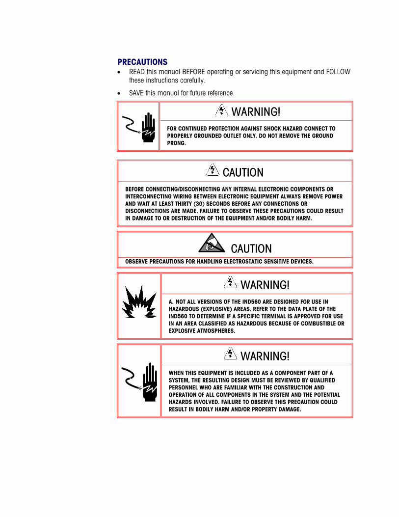
PRECAUTIONS • READ this manual BEFORE operating or servicing this equipment and FOLLOW
these instructions carefully.
• SAVE this manual for future reference.
WARNING! FOR CONTINUED PROTECTION AGAINST SHOCK HAZARD CONNECT TO PROPERLY GROUNDED OUTLET ONLY. DO NOT REMOVE THE GROUND PRONG.
CAUTION BEFORE CONNECTING/DISCONNECTING ANY INTERNAL ELECTRONIC COMPONENTS OR INTERCONNECTING WIRING BETWEEN ELECTRONIC EQUIPMENT ALWAYS REMOVE POWER AND WAIT AT LEAST THIRTY (30) SECONDS BEFORE ANY CONNECTIONS OR DISCONNECTIONS ARE MADE. FAILURE TO OBSERVE THESE PRECAUTIONS COULD RESULT IN DAMAGE TO OR DESTRUCTION OF THE EQUIPMENT AND/OR BODILY HARM.
CAUTION OBSERVE PRECAUTIONS FOR HANDLING ELECTROSTATIC SENSITIVE DEVICES.
WARNING! A. NOT ALL VERSIONS OF THE IND560 ARE DESIGNED FOR USE IN HAZARDOUS (EXPLOSIVE) AREAS. REFER TO THE DATA PLATE OF THE IND560 TO DETERMINE IF A SPECIFIC TERMINAL IS APPROVED FOR USE IN AN AREA CLASSIFIED AS HAZARDOUS BECAUSE OF COMBUSTIBLE OR EXPLOSIVE ATMOSPHERES.
WARNING! WHEN THIS EQUIPMENT IS INCLUDED AS A COMPONENT PART OF A SYSTEM, THE RESULTING DESIGN MUST BE REVIEWED BY QUALIFIED PERSONNEL WHO ARE FAMILIAR WITH THE CONSTRUCTION AND OPERATION OF ALL COMPONENTS IN THE SYSTEM AND THE POTENTIAL HAZARDS INVOLVED. FAILURE TO OBSERVE THIS PRECAUTION COULD RESULT IN BODILY HARM AND/OR PROPERTY DAMAGE.
Contents Chapter 1.0 A-B RIO Kit Option ........................................... 1-1
Overview................................................................................... 1-1 Communications ............................................................................1-1 Node/Rack Address ........................................................................1-2 Data Formats .................................................................................1-2
Data Definition ........................................................................... 1-2 Data Integrity .................................................................................1-3 Discrete Data .................................................................................1-3 Message Slots................................................................................1-5 Integer and Division........................................................................1-6 Floating Point.................................................................................1-9 Block Transfer ..............................................................................1-20 Block Transfer Formats..................................................................1-21 Controlling the Discrete I/O Using a PLC Interface .............................1-22
Hardware Setup ....................................................................... 1-22 Wiring.........................................................................................1-22
Software Setup ......................................................................... 1-22 PLC-RIO Setup Sub-Block ..............................................................1-23
Troubleshooting ....................................................................... 1-24 Allen-Bradley RIO Option Kit Part Numbers .................................. 1-24 Interfacing Examples ................................................................ 1-25
Chapter 2.0 PROFIBUS Kit Option........................................ 2-1 Overview................................................................................... 2-1
Communications ............................................................................2-1 Node/Rack Address ........................................................................2-3 Data Formats .................................................................................2-3
Data Integrity ............................................................................. 2-4 Discrete Data ............................................................................. 2-4 Integer and Division.................................................................... 2-6
Floating Point.................................................................................2-9 Floating Point Numbers............................................................. 2-18
Shared Data.................................................................................2-19 Discrete Data I/O Space Usage Comparison.....................................2-20 IND560 PROFIBUS Message Mapping ............................................2-23 Controlling Discrete I/O Using a PLC Interface ..................................2-29
Hardware Setup ....................................................................... 2-30 Wiring.........................................................................................2-30
Software Setup ......................................................................... 2-30
PROFIBUS Setup Sub-Block ...........................................................2-31 PROFIBUS GSD or Type Files..........................................................2-31
PROFIBUS Option Kit Part Numbers ............................................ 2-33 Interfacing Examples ................................................................ 2-34
Chapter 3.0 Analog Output Kit Option .................................. 3-1 Specifications ............................................................................ 3-1 Installation ................................................................................ 3-2 Setup In the IND560 Terminal ...................................................... 3-2
Analog Output Setup Sub-Block........................................................3-3 Wiring ...................................................................................... 3-4 Analog Output Kit Spare Parts ...................................................... 3-5
1-1
Chapter 1.0 A-B RIO Kit Option
Overview The A-B RIO Kit option enables the IND560 terminal to communicate to Allen-Bradley Programmable Logic Controllers (PLCs) through direct connection to the A-B RIO network. The option consists of a backplane-compatible I/O module and software that resides in the IND560 terminal, which implements the data exchange.
The A-B RIO Kit option has the following features:
• A-B RIO Node Adapter Chip Set (licensed from Allen-Bradley) and termination for the A-B network cable (blue hose) on a three-position removable terminal block.
• User programmable RIO communication parameters are configured in software set up through the terminal keyboard/display. The parameters are as follows:
– 57.6K, 115.2K, or 230.4K baud rate
– 1/4, 1/2, 3/4, full rack (depends upon the number of scales/interface)
– Rack address
– Starting quarter
– Last rack designation
• Capability for bi-directional discrete mode communications of weight, display increments, status, and control data between the PLC and the terminal.
• Capability for bi-directional block transfer communication of many IND560 terminal data variables. (Future - The option also allows the PLC to write messages to the terminal's display area.)
Communications The IND560 terminal utilizes component parts that are provided by Allen-Bradley to ensure complete compatibility with the Allen-Bradley RIO network. An IND560 terminal is recognized as an RIO (Allen-Bradley) device by the PLC.
Each option connected to the Allen-Bradley RIO network represents a physical node. The connection is facilitated by a three-position removable terminal block on the option card back panel. These terminals correspond to the terminals on the A-B PLC RIO connector.
IND560 PLC Interface Manual
1-2
The wiring between the PLC and the RIO connector uses the standard RIO cable used by Allen-Bradley (Figure 1-1). This cable is often referred to as the “blue hose.” The cable installation procedures and specification including distance and termination requirements are the same as recommended by Allen-Bradley for the RIO network.
The IND560 terminal’s baud rate is programmed through Communication -> PLC -> A-B RIO in the setup menu.
Node/Rack Address Although each RIO option represents one physical node, the addressing of the node is defined as a logical rack address. This address is chosen by the system designer, and then programmed into the terminal and PLC. The IND560 terminal’s address is programmed through Communication -> PLC -> A-B RIO in the setup menu. IND560 address entry is in decimal, most PLC address entry is in octal.
The IND560 terminal’s setup capabilities allow selection of the logical rack address, starting quarter, and designation of the last rack, and the number of quarters (Message Slots). Quarters must be contiguous in a single, logical rack, so the starting quarter must be low enough to accommodate all of the required data for the scales in a single, logical rack. The IND560 will determine the number of quarters needed for the chosen data format and number of configurable Message Slots. It only allows selection of the possible starting quarters and maximum Message Slots.
Data Formats The A-B RIO Kit option has two types of data exchanges: discrete data and block transfer data.
Discrete data is continuously available. The A-B RIO Kit option has its own logical rack address to send and receive information to and from the PLC. Discrete data is always sent even when the optional block transfer data is used.
Block transfer data is available when the option is enabled through the IND560 Communication -> PLC –> A-B RIO setup menu. This data is used to pass information that cannot be sent by the discrete data because of size or process speed limitations. See the Data Definition section for more information.
Data Definition The A-B RIO Kit option uses two types of data for its communication with PLCs: discrete data and block transfer data. Discrete data is always available. The data transfer is accomplished via the PLC’s I/O messaging. Block transfer data is only available if this data option is enabled through the Communications -> PLC -> A-B RIO setup menu. If the block transfer data option is enabled, it is provided in addition to the discrete data. Block transfer data requires “block transfer” ladder sequence programming to accomplish the data transfer between the IND560 and PLC.
IND560 PLC Interface Manual
1-3
Data Integrity The IND560 has specific bits to allow the PLC to confirm that data was received without interrupt and the IND560 is not in an error condition. It is important to monitor these bits. Any PLC code should use them to confirm the integrity of the data received for the IND560. Refer to the data charts for specific information regarding the Data OK, Update in Progress, Data Integrity bits and their usage.
Discrete Data There are three formats of discrete data available with the A-B RIO Kit option: integer, division, and floating point. Only one type of data format may be selected and used by IND560’s sharing the same A-B RIO logical rack address.
The integer and division formats allow bi-directional communication of discrete bit encoded information or 16 bit binary word (see table 1-3 note 9 for explanation) numerical values. The IND560 provides one quarter rack of data per Message Slot.
The floating-point format allows bi-directional communication of discrete bit encoded information or numeric data encoded in IEEE 754, single precision floating point format. The IND560 provides one-half rack of data per Message Slot.
The format of discrete data will affect the amount of rack space required. Integer and division formats require one-quarter rack per IND560 (two 16-bit words of input and two 16-bit words of output data) Message Slot. One IND560, with 1 Message Slot, would use a quarter rack; two IND560’s, with 1 Message Slot, would use a half rack; three IND560’s, with 1 Message Slot, would use three-quarters of a rack; and four IND560’s, with 1 Message Slot, would use a full rack.
The floating-point format requires more space per IND560 because floating point data uses two 16-bit words of data to represent just the numeric data alone. The floating point format uses one full rack per IND560 (four 16-bit words of input and four 16-bit words of output data) per Message Slot.
Selection of the appropriate format depends on issues such as the range or capacity of the scale used in the application. The integer format can represent a numerical value up to 32,767. The division format can represent a value up to 32,767 scale divisions or increments. The floating-point format can represent a value encoded in IEEE 754, single precision floating point format.
IND560 PLC Interface Manual
1-4
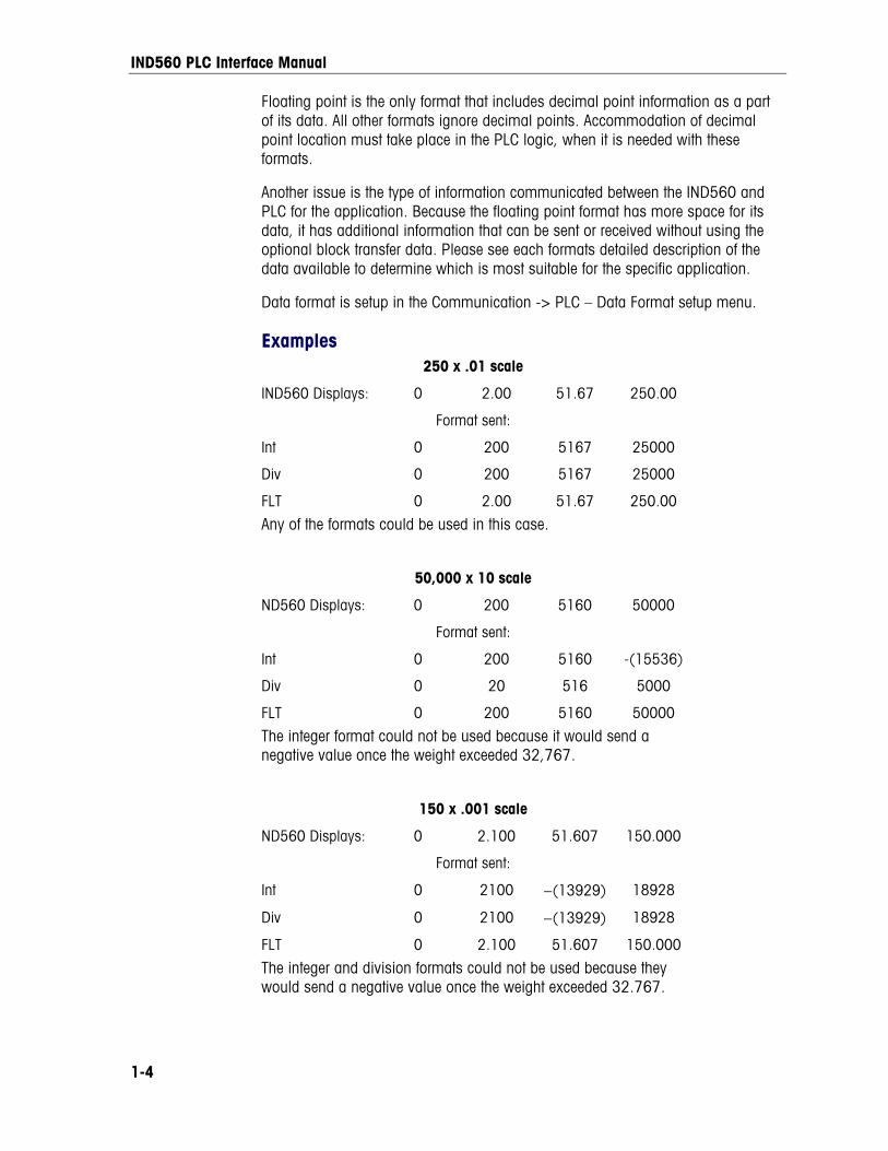
Floating point is the only format that includes decimal point information as a part of its data. All other formats ignore decimal points. Accommodation of decimal point location must take place in the PLC logic, when it is needed with these formats.
Another issue is the type of information communicated between the IND560 and PLC for the application. Because the floating point format has more space for its data, it has additional information that can be sent or received without using the optional block transfer data. Please see each formats detailed description of the data available to determine which is most suitable for the specific application.
Data format is setup in the Communication -> PLC – Data Format setup menu.
Examples 250 x .01 scale
IND560 Displays: 0 2.00 51.67 250.00
Format sent:
Int 0 200 5167 25000
Div 0 200 5167 25000
FLT 0 2.00 51.67 250.00
Any of the formats could be used in this case.
50,000 x 10 scale
ND560 Displays: 0 200 5160 50000
Format sent:
Int 0 200 5160 -(15536)
Div 0 20 516 5000
FLT 0 200 5160 50000
The integer format could not be used because it would send a negative value once the weight exceeded 32,767.
150 x .001 scale
ND560 Displays: 0 2.100 51.607 150.000
Format sent:
Int 0 2100 −(13929) 18928
Div 0 2100 −(13929) 18928
FLT 0 2.100 51.607 150.000
The integer and division formats could not be used because they would send a negative value once the weight exceeded 32.767.
IND560 PLC Interface Manual
1-5
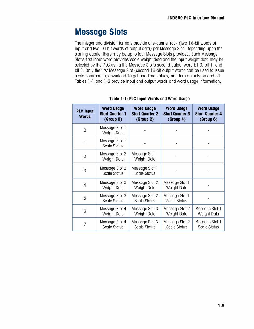
Message Slots The integer and division formats provide one-quarter rack (two 16-bit words of input and two 16-bit words of output data) per Message Slot. Depending upon the starting quarter there may be up to four Message Slots provided. Each Message Slot’s first input word provides scale weight data and the input weight data may be selected by the PLC using the Message Slot’s second output word bit 0, bit 1, and bit 2. Only the first Message Slot (second 16-bit output word) can be used to issue scale commands, download Target and Tare values, and turn outputs on and off. Tables 1-1 and 1-2 provide input and output words and word usage information.
Table 1-1: PLC Input Words and Word Usage
PLC Input Words
Word Usage Start Quarter 1
(Group 0)
Word Usage Start Quarter 2
(Group 2)
Word Usage Start Quarter 3
(Group 4)
Word Usage Start Quarter 4
(Group 6)
0 Message Slot 1 Weight Data - - -
1 Message Slot 1 Scale Status
- - -
2 Message Slot 2 Weight Data
Message Slot 1 Weight Data
- -
3 Message Slot 2 Scale Status
Message Slot 1 Scale Status - -
4 Message Slot 3 Weight Data
Message Slot 2 Weight Data
Message Slot 1 Weight Data
-
5 Message Slot 3 Scale Status
Message Slot 2 Scale Status
Message Slot 1 Scale Status -
6 Message Slot 4 Weight Data
Message Slot 3 Weight Data
Message Slot 2 Weight Data
Message Slot 1 Weight Data
7 Message Slot 4 Scale Status
Message Slot 3 Scale Status
Message Slot 2 Scale Status
Message Slot 1 Scale Status
IND560 PLC Interface Manual
1-6
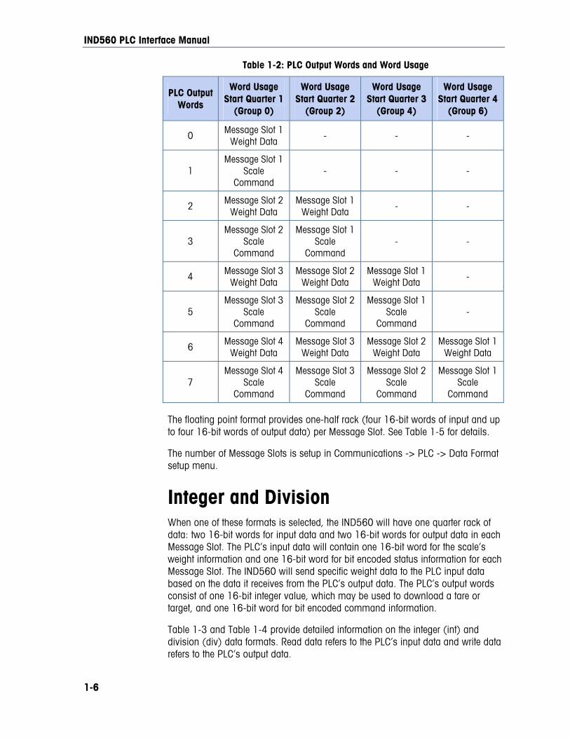
Table 1-2: PLC Output Words and Word Usage
PLC Output Words
Word Usage Start Quarter 1
(Group 0)
Word Usage Start Quarter 2
(Group 2)
Word Usage Start Quarter 3
(Group 4)
Word Usage Start Quarter 4
(Group 6)
0 Message Slot 1 Weight Data
- - -
1 Message Slot 1
Scale Command
- - -
2 Message Slot 2 Weight Data
Message Slot 1 Weight Data
- -
3 Message Slot 2
Scale Command
Message Slot 1 Scale
Command - -
4 Message Slot 3 Weight Data
Message Slot 2 Weight Data
Message Slot 1 Weight Data
-
5 Message Slot 3
Scale Command
Message Slot 2 Scale
Command
Message Slot 1 Scale
Command -
6 Message Slot 4 Weight Data
Message Slot 3 Weight Data
Message Slot 2 Weight Data
Message Slot 1 Weight Data
7 Message Slot 4
Scale Command
Message Slot 3 Scale
Command
Message Slot 2 Scale
Command
Message Slot 1 Scale
Command The floating point format provides one-half rack (four 16-bit words of input and up to four 16-bit words of output data) per Message Slot. See Table 1-5 for details.
The number of Message Slots is setup in Communications -> PLC -> Data Format setup menu.
Integer and Division When one of these formats is selected, the IND560 will have one quarter rack of data: two 16-bit words for input data and two 16-bit words for output data in each Message Slot. The PLC’s input data will contain one 16-bit word for the scale’s weight information and one 16-bit word for bit encoded status information for each Message Slot. The IND560 will send specific weight data to the PLC input data based on the data it receives from the PLC’s output data. The PLC’s output words consist of one 16-bit integer value, which may be used to download a tare or target, and one 16-bit word for bit encoded command information.
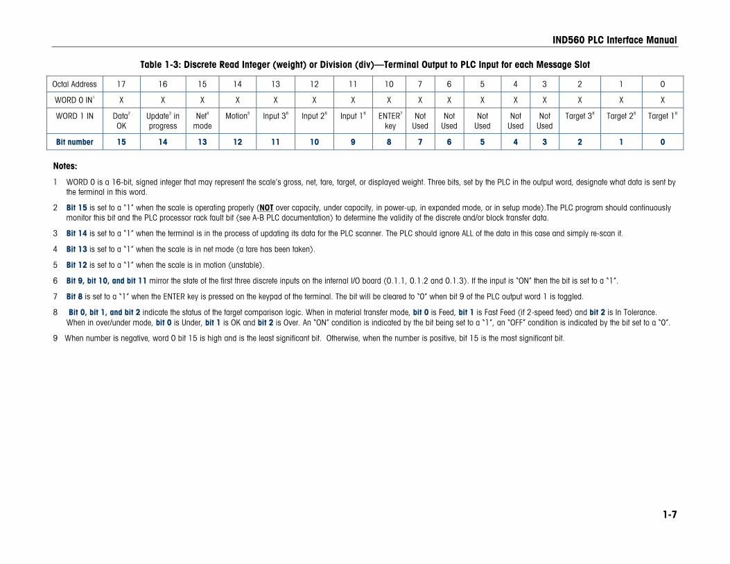
Table 1-3 and Table 1-4 provide detailed information on the integer (int) and division (div) data formats. Read data refers to the PLC’s input data and write data refers to the PLC’s output data.
IND560 PLC Interface Manual
1-7
Table 1-3: Discrete Read Integer (weight) or Division (div)—Terminal Output to PLC Input for each Message Slot
Octal Address 17 16 15 14 13 12 11 10 7 6 5 4 3 2 1 0
WORD 0 IN1 X X X X X X X X X X X X X X X X
WORD 1 IN Data2 OK
Update3 in progress
Net4 mode
Motion5 Input 36 Input 26 Input 16 ENTER7 key
Not Used
Not Used
Not Used
Not Used
Not Used
Target 38 Target 28 Target 18
Bit number 15 14 13 12 11 10 9 8 7 6 5 4 3 2 1 0
Notes:
1 WORD 0 is a 16-bit, signed integer that may represent the scale’s gross, net, tare, target, or displayed weight. Three bits, set by the PLC in the output word, designate what data is sent by the terminal in this word.
2 Bit 15 is set to a “1” when the scale is operating properly (NOT over capacity, under capacity, in power-up, in expanded mode, or in setup mode).The PLC program should continuously monitor this bit and the PLC processor rack fault bit (see A-B PLC documentation) to determine the validity of the discrete and/or block transfer data.
3 Bit 14 is set to a “1” when the terminal is in the process of updating its data for the PLC scanner. The PLC should ignore ALL of the data in this case and simply re-scan it.
4 Bit 13 is set to a “1” when the scale is in net mode (a tare has been taken).
5 Bit 12 is set to a “1” when the scale is in motion (unstable).
6 Bit 9, bit 10, and bit 11 mirror the state of the first three discrete inputs on the internal I/O board (0.1.1, 0.1.2 and 0.1.3). If the input is “ON” then the bit is set to a “1”.
7 Bit 8 is set to a “1” when the ENTER key is pressed on the keypad of the terminal. The bit will be cleared to “0” when bit 9 of the PLC output word 1 is toggled.
8 Bit 0, bit 1, and bit 2 indicate the status of the target comparison logic. When in material transfer mode, bit 0 is Feed, bit 1 is Fast Feed (if 2-speed feed) and bit 2 is In Tolerance. When in over/under mode, bit 0 is Under, bit 1 is OK and bit 2 is Over. An “ON” condition is indicated by the bit being set to a “1”, an “OFF” condition is indicated by the bit set to a “0”.
9 When number is negative, word 0 bit 15 is high and is the least significant bit. Otherwise, when the number is positive, bit 15 is the most significant bit.
IND560 PLC Interface Manual
1-8
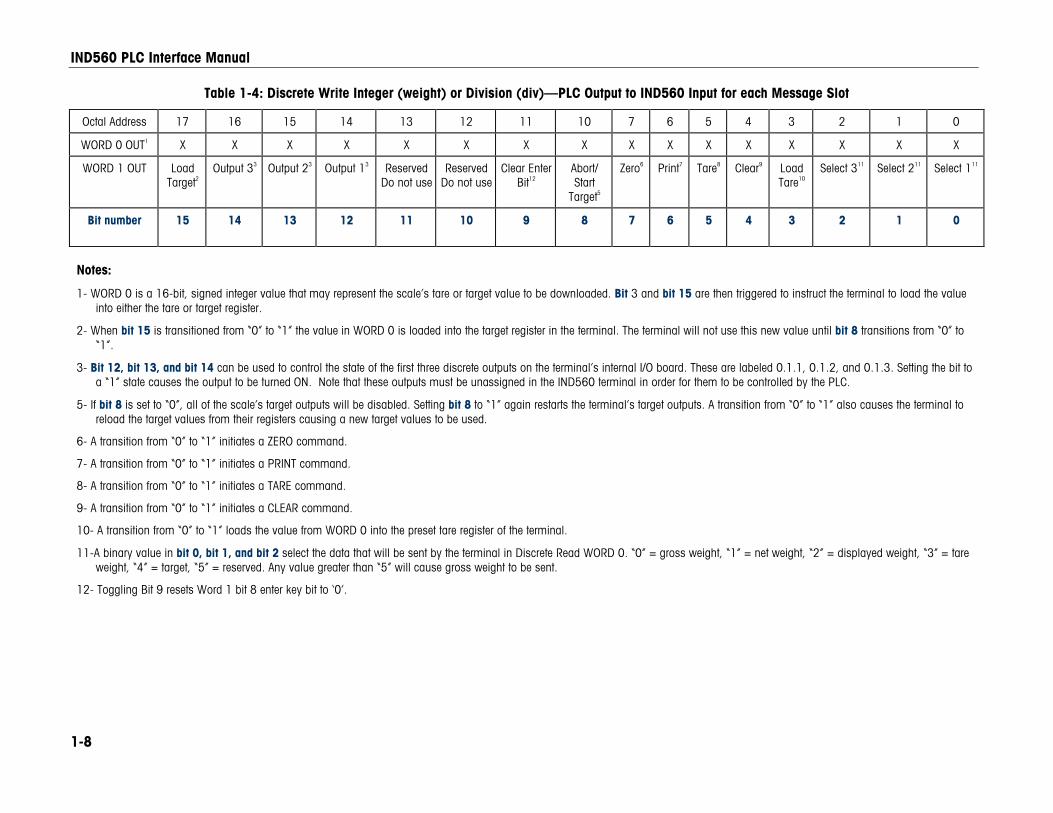
Table 1-4: Discrete Write Integer (weight) or Division (div)—PLC Output to IND560 Input for each Message Slot
Octal Address 17 16 15 14 13 12 11 10 7 6 5 4 3 2 1 0
WORD 0 OUT1 X X X X X X X X X X X X X X X X
WORD 1 OUT Load Target2
Output 33 Output 23 Output 13 ReservedDo not use
ReservedDo not use
Clear Enter Bit12
Abort/ Start
Target5
Zero6 Print7 Tare8 Clear9 Load Tare10
Select 311 Select 211 Select 111
Bit number 15 14 13 12 11 10 9 8
7 6 5 4 3 2 1 0
Notes:
1- WORD 0 is a 16-bit, signed integer value that may represent the scale’s tare or target value to be downloaded. Bit 3 and bit 15 are then triggered to instruct the terminal to load the value into either the tare or target register.
2- When bit 15 is transitioned from “0” to “1” the value in WORD 0 is loaded into the target register in the terminal. The terminal will not use this new value until bit 8 transitions from “0” to “1”.
3- Bit 12, bit 13, and bit 14 can be used to control the state of the first three discrete outputs on the terminal’s internal I/O board. These are labeled 0.1.1, 0.1.2, and 0.1.3. Setting the bit to a “1” state causes the output to be turned ON. Note that these outputs must be unassigned in the IND560 terminal in order for them to be controlled by the PLC.
5- If bit 8 is set to “0”, all of the scale’s target outputs will be disabled. Setting bit 8 to “1” again restarts the terminal’s target outputs. A transition from “0” to “1” also causes the terminal to reload the target values from their registers causing a new target values to be used.
6- A transition from “0” to “1” initiates a ZERO command.
7- A transition from “0” to “1” initiates a PRINT command.
8- A transition from “0” to “1” initiates a TARE command.
9- A transition from “0” to “1” initiates a CLEAR command.
10- A transition from “0” to “1” loads the value from WORD 0 into the preset tare register of the terminal.
11-A binary value in bit 0, bit 1, and bit 2 select the data that will be sent by the terminal in Discrete Read WORD 0. “0” = gross weight, “1” = net weight, “2” = displayed weight, “3” = tare weight, “4” = target, “5” = reserved. Any value greater than “5” will cause gross weight to be sent.
12- Toggling Bit 9 resets Word 1 bit 8 enter key bit to ‘0’.
IND560 PLC Interface Manual
1-9
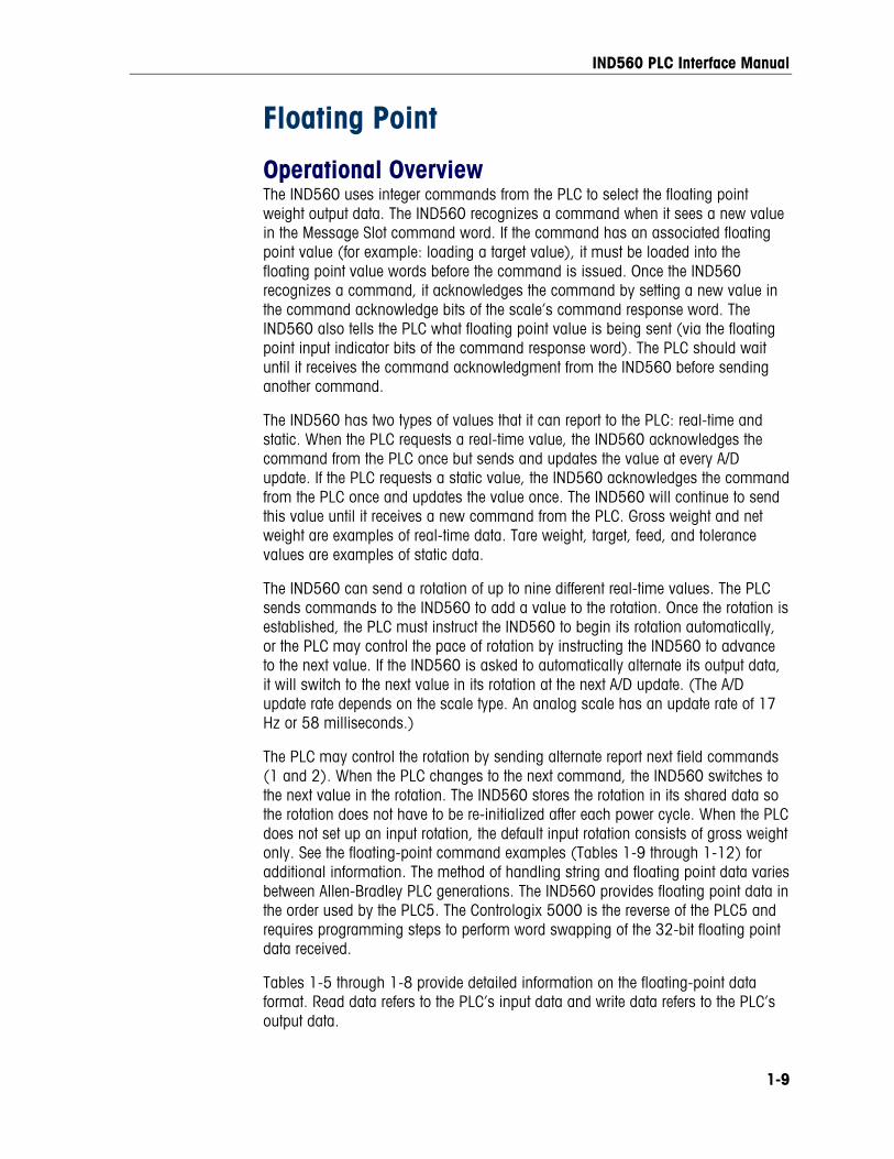
Floating Point
Operational Overview The IND560 uses integer commands from the PLC to select the floating point weight output data. The IND560 recognizes a command when it sees a new value in the Message Slot command word. If the command has an associated floating point value (for example: loading a target value), it must be loaded into the floating point value words before the command is issued. Once the IND560 recognizes a command, it acknowledges the command by setting a new value in the command acknowledge bits of the scale’s command response word. The IND560 also tells the PLC what floating point value is being sent (via the floating point input indicator bits of the command response word). The PLC should wait until it receives the command acknowledgment from the IND560 before sending another command.
The IND560 has two types of values that it can report to the PLC: real-time and static. When the PLC requests a real-time value, the IND560 acknowledges the command from the PLC once but sends and updates the value at every A/D update. If the PLC requests a static value, the IND560 acknowledges the command from the PLC once and updates the value once. The IND560 will continue to send this value until it receives a new command from the PLC. Gross weight and net weight are examples of real-time data. Tare weight, target, feed, and tolerance values are examples of static data.
The IND560 can send a rotation of up to nine different real-time values. The PLC sends commands to the IND560 to add a value to the rotation. Once the rotation is established, the PLC must instruct the IND560 to begin its rotation automatically, or the PLC may control the pace of rotation by instructing the IND560 to advance to the next value. If the IND560 is asked to automatically alternate its output data, it will switch to the next value in its rotation at the next A/D update. (The A/D update rate depends on the scale type. An analog scale has an update rate of 17 Hz or 58 milliseconds.)
The PLC may control the rotation by sending alternate report next field commands (1 and 2). When the PLC changes to the next command, the IND560 switches to the next value in the rotation. The IND560 stores the rotation in its shared data so the rotation does not have to be re-initialized after each power cycle. When the PLC does not set up an input rotation, the default input rotation consists of gross weight only. See the floating-point command examples (Tables 1-9 through 1-12) for additional information. The method of handling string and floating point data varies between Allen-Bradley PLC generations. The IND560 provides floating point data in the order used by the PLC5. The Contrologix 5000 is the reverse of the PLC5 and requires programming steps to perform word swapping of the 32-bit floating point data received.
Tables 1-5 through 1-8 provide detailed information on the floating-point data format. Read data refers to the PLC’s input data and write data refers to the PLC’s output data.

IND560 PLC Interface Manual
1-10
Table 1-5: Discrete Read Floating Point (float)—IND560 Output to PLC Input for each Message Slot
Octal Address 17 16 15 14 13 12 11 10 7 6 5 4 3 2 1 0
WORD 0 Command Response
Cmnd Ack 21
Cmnd
Ack 11
Data2 integrity1
FP Input Ind 53
FP Input Ind 43
FP Input Ind 33
FP Input Ind 23
FP Input Ind 13
RESERVED
WORD 14 FP value
X X X X X X X X X X X X X X X X
WORD 2 4 FP value
X X X X X X X X X X X X X X X X
WORD 3 Status
Data5 OK Data2 integrity 2
Net6
mode
Motion7 Input 38 Input 28 Input 18 ENTER key9
Reserved Do not
use
Reserved Do not
use
Always“1”10
Target 311
Not Used
Target 211
Not Used Target 111
Bit number 15 14 13 12 11 10 9 8 7 6 5 4 3 2 1 0
Notes: 1 Bit 14 and bit 15 (Command Acknowledge bits) are used by the terminal to inform the PLC that it has received a new, valid command. The terminal rotates sequentially among values 1,
2, 3, 1, 2, 3, 1, 2, … to acknowledge it has processed a new command. 2 The Data Integrity bit in WORD 0 - bit 13 is used in conjunction with the bit in WORD 3 - bit 14 to insure that the floating point data is valid. For the data to be valid both bits must have
the same polarity. These bits will change to the opposite state every A/D (scale) update. If they do not have the same value the data is invalid and the PLC should ignore ALL of the data in this case and re-scan it.
3 The Floating Point Input Indication bits (WORD 0, bits 8-12) are used to determine what type of data is being sent in the floating point value (WORD 1 and WORD 2). These bits correspond to a decimal value of 0-31 that represents a particular type of data. See the Floating Point Input Indication Table to determine what type of data.
4 The bits in WORD 1 and WORD 2 are a single-precision floating point value that may represent the scale’s gross, tare, net, target, fine gross, fine tare, fine net, or filter setting data. The PLC command in the respective scale’s output word determines what data will be sent.
5 Bit 15 is set to a “1” when the scale is operating properly (NOT over capacity, under capacity, in power-up, in expanded mode, or in diagnostic mode). The PLC program should continuously monitor this bit and the PLC processor rack fault bit (see A-B PLC documentation) to determine the validity of the discrete and/or block transfer data.
6 Bit 13 is set to a “1” when the scale is in net mode (a tare has been taken). 7 Bit 12 is set to a “1” when the scale is in motion (unstable). 8 Bit 9, bit 10, and bit 11 mirror the state of the first three discrete inputs on the internal I/O board (0.1.1, 0.1.2 and 0.1.3). If the input is “ON” then the bit is set to a “1”. 9 Bit 8 is set to a “1” when the ENTER key is pressed on the keypad of the terminal. The bit will be cleared to “0” when the PLC sends floating point command 75 to the IND560 terminal. 10 This bit will always be set to a “1”. 11 The 3 target bits (bit 0, bit 2, and bit 4) indicate the status of the target comparison logic. When in material transfer mode, bit 0 is Feed, bit 2 is Fast Feed (if 2-speed feed) and bit 4 is
In Tolerance. When in over/under mode, bit 0 is Under, bit 2 is OK and bit 4 is Over. An “ON” condition is indicated by the bit being set to a “1”, an “OFF” condition is indicated by the bit set to a “0”.
IND560 PLC Interface Manual
1-11
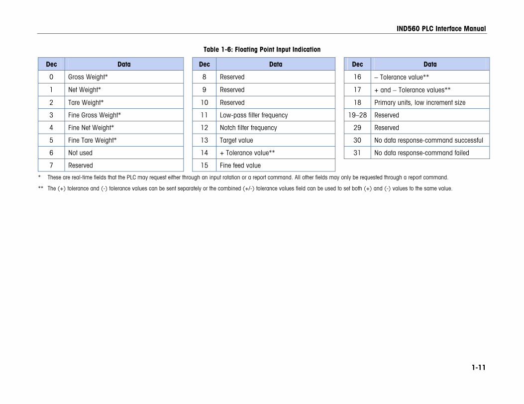
Table 1-6: Floating Point Input Indication
Dec Data Dec Data Dec Data
0 Gross Weight* 8 Reserved 16 − Tolerance value**
1 Net Weight* 9 Reserved 17 + and − Tolerance values**
2 Tare Weight* 10 Reserved 18 Primary units, low increment size
3 Fine Gross Weight* 11 Low-pass filter frequency 19–28 Reserved
4 Fine Net Weight* 12 Notch filter frequency 29 Reserved
5 Fine Tare Weight* 13 Target value 30 No data response-command successful
6 Not used 14 + Tolerance value** 31 No data response-command failed
7 Reserved 15 Fine feed value
* These are real-time fields that the PLC may request either through an input rotation or a report command. All other fields may only be requested through a report command.
** The (+) tolerance and (-) tolerance values can be sent separately or the combined (+/-) tolerance values field can be used to set both (+) and (-) values to the same value.
IND560 PLC Interface Manual
1-12
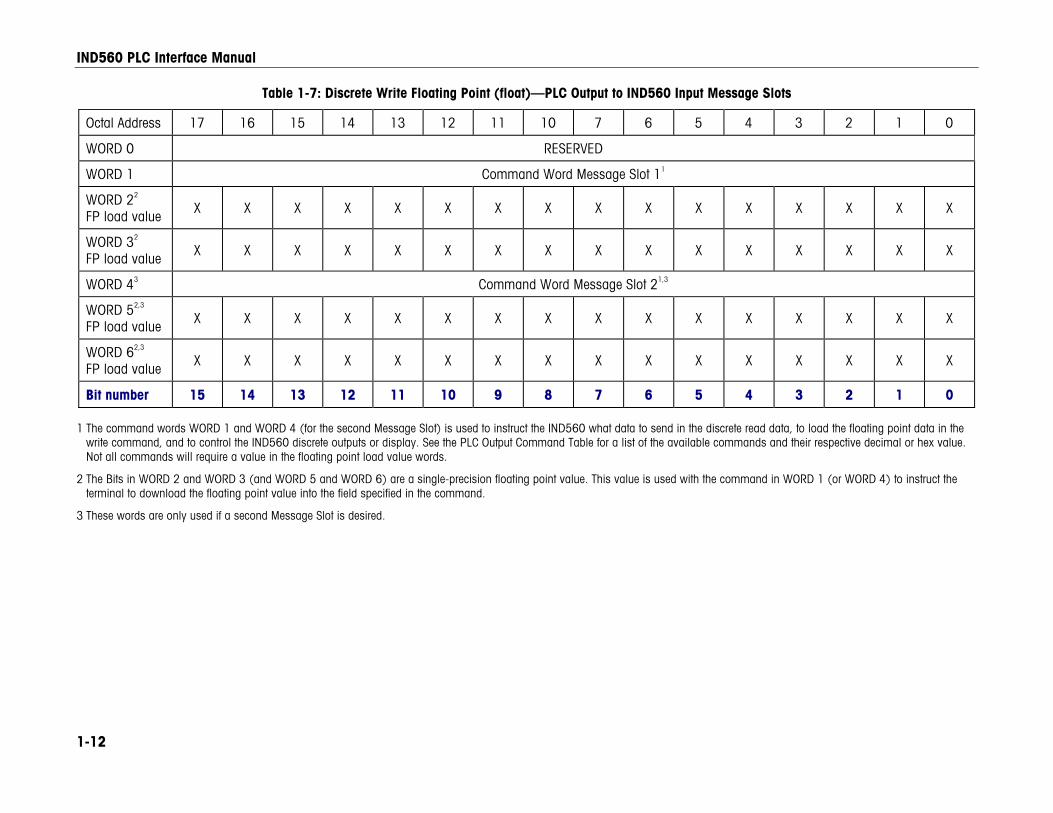
Table 1-7: Discrete Write Floating Point (float)—PLC Output to IND560 Input Message Slots
Octal Address 17 16 15 14 13 12 11 10 7 6 5 4 3 2 1 0
WORD 0 RESERVED
WORD 1 Command Word Message Slot 11
WORD 22 FP load value
X X X X X X X X X X X X X X X X
WORD 32 FP load value X X X X X X X X X X X X X X X X
WORD 43 Command Word Message Slot 21,3
WORD 52,3
FP load value X X X X X X X X X X X X X X X X
WORD 62,3 FP load value X X X X X X X X X X X X X X X X
Bit number 15 14 13 12 11 10 9 8 7 6 5 4 3 2 1 0
1 The command words WORD 1 and WORD 4 (for the second Message Slot) is used to instruct the IND560 what data to send in the discrete read data, to load the floating point data in the write command, and to control the IND560 discrete outputs or display. See the PLC Output Command Table for a list of the available commands and their respective decimal or hex value. Not all commands will require a value in the floating point load value words.
2 The Bits in WORD 2 and WORD 3 (and WORD 5 and WORD 6) are a single-precision floating point value. This value is used with the command in WORD 1 (or WORD 4) to instruct the terminal to download the floating point value into the field specified in the command.
3 These words are only used if a second Message Slot is desired.
IND560 PLC Interface Manual
1-13
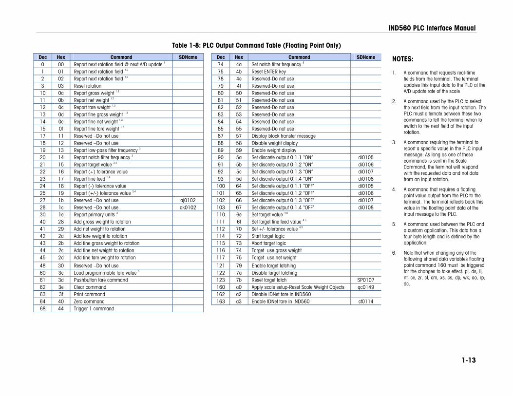
Table 1-8: PLC Output Command Table (Floating Point Only)
Dec Hex Command SDName Dec Hex Command SDName 0 00 Report next rotation field @ next A/D update 1 74 4a Set notch filter frequency 5 1 01 Report next rotation field 1,2 75 4b Reset ENTER key 2 02 Report next rotation field 1,2 78 4e Reserved-Do not use 3 03 Reset rotation 79 4f Reserved-Do not use
10 0a Report gross weight 1,3 80 50 Reserved-Do not use 11 0b Report net weight 1,3 81 51 Reserved-Do not use 12 0c Report tare weight 1,3 82 52 Reserved-Do not use 13 0d Report fine gross weight 1,3 83 53 Reserved-Do not use 14 0e Report fine net weight 1,3 84 54 Reserved-Do not use 15 0f Report fine tare weight 1,3 85 55 Reserved-Do not use 17 11 Reserved –Do not use 87 57 Display block transfer message 18 12 Reserved –Do not use 88 58 Disable weight display 19 13 Report low-pass filter frequency 3 89 59 Enable weight display 20 14 Report notch filter frequency 3 90 5a Set discrete output 0.1.1 “ON” di0105 21 15 Report target value 3,4 91 5b Set discrete output 0.1.2 “ON” di0106 22 16 Report (+) tolerance value 92 5c Set discrete output 0.1.3 “ON” di0107 23 17 Report fine feed 3,4 93 5d Set discrete output 0.1.4 “ON” di0108 24 18 Report (-) tolerance value 100 64 Set discrete output 0.1.1 “OFF” di0105 25 19 Report (+/-) tolerance value 3,4 101 65 Set discrete output 0.1.2 “OFF” di0106 27 1b Reserved –Do not use aj0102 102 66 Set discrete output 0.1.3 “OFF” di0107 28 1c Reserved –Do not use ak0102 103 67 Set discrete output 0.1.4 “OFF” di0108 30 1e Report primary units 3 110 6e Set target value 4,5 40 28 Add gross weight to rotation 111 6f Set target fine feed value 4,5 41 29 Add net weight to rotation 112 70 Set +/- tolerance value 4,5 42 2a Add tare weight to rotation 114 72 Start target logic 43 2b Add fine gross weight to rotation 115 73 Abort target logic 44 2c Add fine net weight to rotation 116 74 Target use gross weight 45 2d Add fine tare weight to rotation 117 75 Target use net weight
48 30 Reserved –Do not use 121 79 Enable target latching 60 3c Load programmable tare value 5 122 7a Disable target latching 61 3d Pushbutton tare command 123 7b Reset target latch SP0107 62 3e Clear command 160 a0 Apply scale setup-Reset Scale Weight Objects qc0149 63 3f Print command 162 a2 Disable IDNet tare in IND560 64 40 Zero command 163 a3 Enable IDNet tare in IND560 ct0114 68 44 Trigger 1 command
NOTES:
1. A command that requests real-time fields from the terminal. The terminal updates this input data to the PLC at the A/D update rate of the scale
2. A command used by the PLC to select the next field from the input rotation. The PLC must alternate between these two commands to tell the terminal when to switch to the next field of the input rotation.
3. A command requiring the terminal to report a specific value in the PLC input message. As long as one of these commands is sent in the Scale Command, the terminal will respond with the requested data and not data from an input rotation.
4. A command that requires a floating point value output from the PLC to the terminal. The terminal reflects back this value in the floating point data of the input message to the PLC.
5. A command used between the PLC and a custom application. This data has a four-byte length and is defined by the application.
6. Note that when changing any of the following shared data variables floating point command 160 must be triggered for the changes to take effect: pl, ds, ll, nt, ce, zr, ct, cm, xs, cs, dp, wk, ao, rp, dc.
IND560 PLC Interface Manual
1-14
Floating Point Data Format and Compatibility In Floating Point Message mode, the PLC and terminal exchange weight, target, and tare data in single-precision floating-point format. The IEEE Standard for Binary Floating-Point Arithmetic, ANSI/IEEE Standard 754-1985, specifies the format for single-precision floating point numbers. It is a 32-bit number that has a 1-bit sign, an 8-bit signed exponent, and a 23-bit mantissa. The 8-bit signed exponent provides scaling of weight data. The 23-bit mantissa allows representation of 8 million unique counts.
Although the single-precision floating point number provides greater numerical precision and flexibility than integer weight representations, it has limitations. The weight representation may not be exact, particularly for the extended-resolution weight fields for high-precision bases.
Some Allen-Bradley PLCs require special integrity checking to communicate floating point numbers across the Remote I/O link. The Allen-Bradley PLC-5 and KTX Scanner Card programs must check two data integrity bits to verify the integrity of the floating point data it reads from the terminal. Allen-Bradley SLC programs always read valid floating-point data from the terminal and do not have to make special checks to guarantee the validity of the floating-point data. The Allen-Bradley PLC-3 and PLC-5/250 cannot support terminals in floating point mode as they cannot guarantee the integrity of the floating-point data.
There are two data integrity bits that the terminal uses to maintain data integrity when communicating with the Allen-Bradley PLC-5 Remote I/O Scanner or KTX Scanner Card. One bit is in the beginning byte of the data; the second is in the ending byte of the data for a scale slot. The PLC program must verify that both data integrity bits have the same polarity for the data in the scale slot to be valid. There is a possibility that the PLC program will see several consecutive invalid reads when the terminal is freely sending weigh updates to the PLC-5 program detects this condition, it should send a new command to the terminal.
The Allen-Bradley SLC PLC programs do not have to make special checks to guarantee the validity of the floating-point data.
The method of handling string and floating point data varies between Allen-Bradley PLC generations. The IND560 provides floating point data in the order used by the PLC5. The Contrologix 5000 is the reverse of the PLC5 and requires programming steps to perform word swapping of the 32-bit floating point data received.
Shared Data Mode The Shared Data mode PLC communications is not available in Allen-Bradley PLCs. Block Transfer communications is used instead.
IND560 PLC Interface Manual
1-15
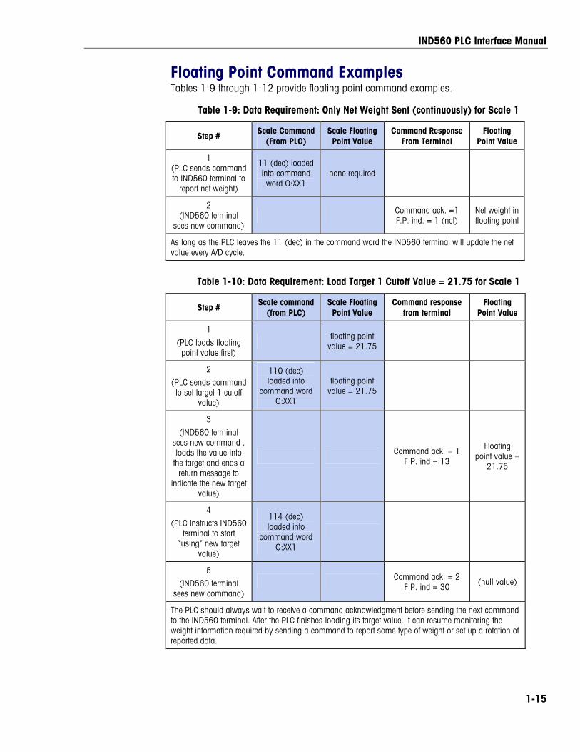
Floating Point Command Examples Tables 1-9 through 1-12 provide floating point command examples.
Table 1-9: Data Requirement: Only Net Weight Sent (continuously) for Scale 1
Step # Scale Command (From PLC)
Scale Floating Point Value
Command Response From Terminal
Floating Point Value
1 (PLC sends command to IND560 terminal to
report net weight)
11 (dec) loaded into command word O:XX1
none required
2 (IND560 terminal
sees new command) Command ack. =1
F.P. ind. = 1 (net) Net weight in floating point
As long as the PLC leaves the 11 (dec) in the command word the IND560 terminal will update the net value every A/D cycle.
Table 1-10: Data Requirement: Load Target 1 Cutoff Value = 21.75 for Scale 1
Step # Scale command (from PLC)
Scale Floating Point Value
Command response from terminal
Floating Point Value
1
(PLC loads floating point value first)
floating point value = 21.75
2
(PLC sends command to set target 1 cutoff
value)
110 (dec) loaded into
command word O:XX1
floating point value = 21.75
3
(IND560 terminal sees new command , loads the value into
the target and ends a return message to
indicate the new target value)
Command ack. = 1 F.P. ind = 13
Floating point value =
21.75
4
(PLC instructs IND560 terminal to start
“using” new target value)
114 (dec) loaded into
command word O:XX1
5
(IND560 terminal sees new command)
Command ack. = 2 F.P. ind = 30
(null value)
The PLC should always wait to receive a command acknowledgment before sending the next command to the IND560 terminal. After the PLC finishes loading its target value, it can resume monitoring the weight information required by sending a command to report some type of weight or set up a rotation of reported data.
IND560 PLC Interface Manual
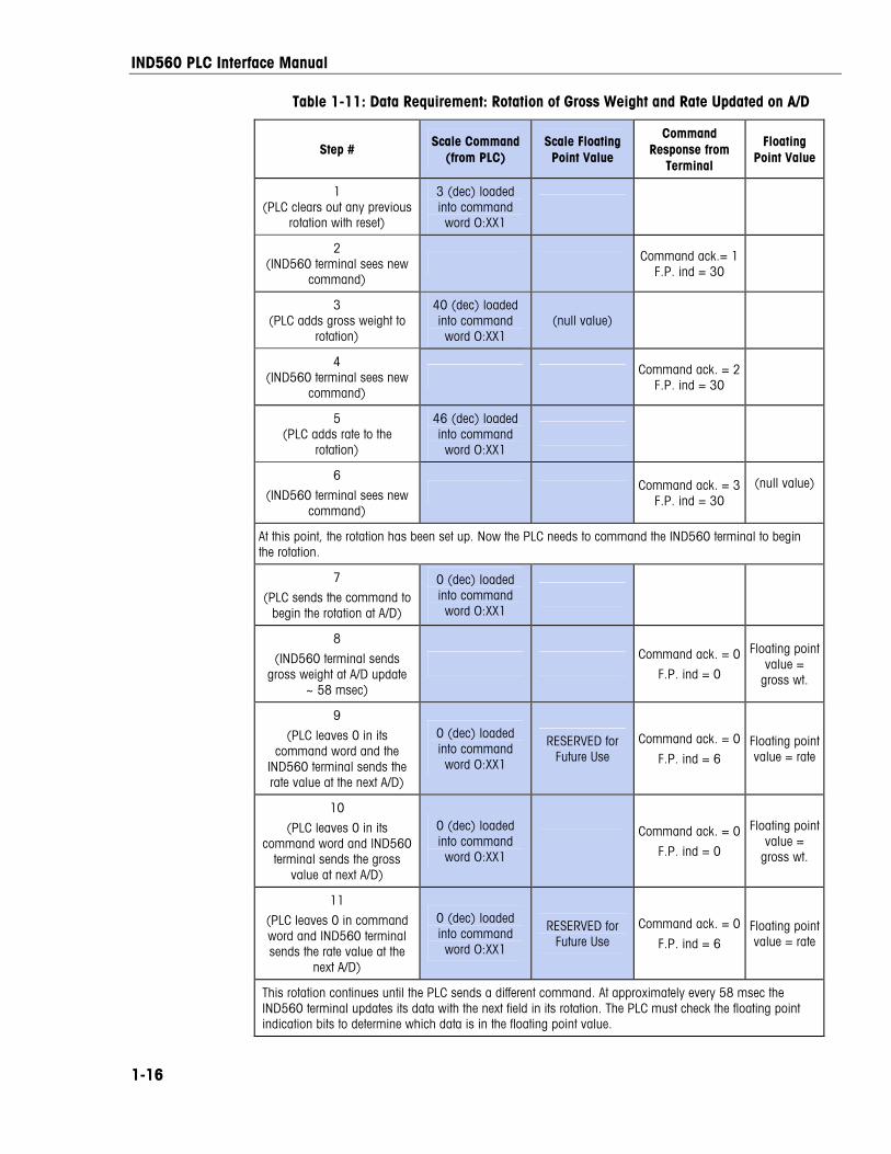
1-16
Table 1-11: Data Requirement: Rotation of Gross Weight and Rate Updated on A/D
Step # Scale Command
(from PLC) Scale Floating Point Value
Command Response from
Terminal
Floating Point Value
1 (PLC clears out any previous
rotation with reset)
3 (dec) loaded into command word O:XX1
2 (IND560 terminal sees new
command) Command ack.= 1
F.P. ind = 30
3 (PLC adds gross weight to
rotation)
40 (dec) loaded into command word O:XX1
(null value)
4 (IND560 terminal sees new
command) Command ack. = 2
F.P. ind = 30
5 (PLC adds rate to the
rotation)
46 (dec) loaded into command word O:XX1
6
(IND560 terminal sees new command)
Command ack. = 3F.P. ind = 30
(null value)
At this point, the rotation has been set up. Now the PLC needs to command the IND560 terminal to begin the rotation.
7
(PLC sends the command to begin the rotation at A/D)
0 (dec) loaded into command word O:XX1
8
(IND560 terminal sends gross weight at A/D update
~ 58 msec)
Command ack. = 0
F.P. ind = 0
Floating point value =
gross wt.
9
(PLC leaves 0 in its command word and the
IND560 terminal sends the rate value at the next A/D)
0 (dec) loaded into command word O:XX1
RESERVED for Future Use
Command ack. = 0
F.P. ind = 6 Floating point value = rate
10
(PLC leaves 0 in its command word and IND560
terminal sends the gross value at next A/D)
0 (dec) loaded into command word O:XX1
Command ack. = 0
F.P. ind = 0
Floating point value =
gross wt.
11
(PLC leaves 0 in command word and IND560 terminal sends the rate value at the
next A/D)
0 (dec) loaded into command word O:XX1
RESERVED for Future Use
Command ack. = 0
F.P. ind = 6 Floating point value = rate
This rotation continues until the PLC sends a different command. At approximately every 58 msec the IND560 terminal updates its data with the next field in its rotation. The PLC must check the floating point indication bits to determine which data is in the floating point value.
IND560 PLC Interface Manual
1-17
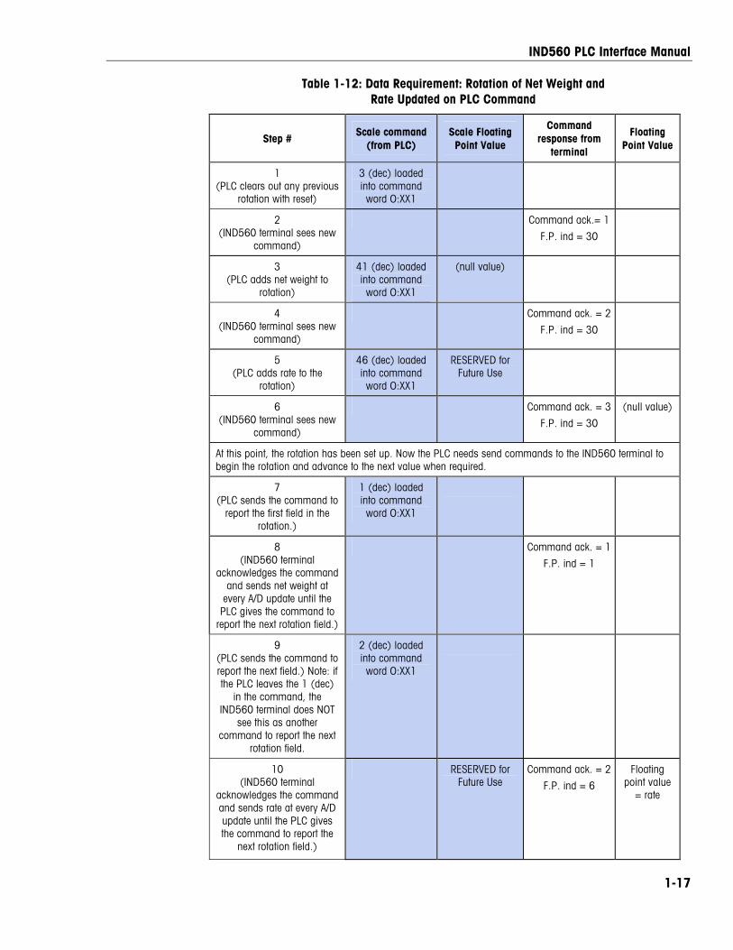
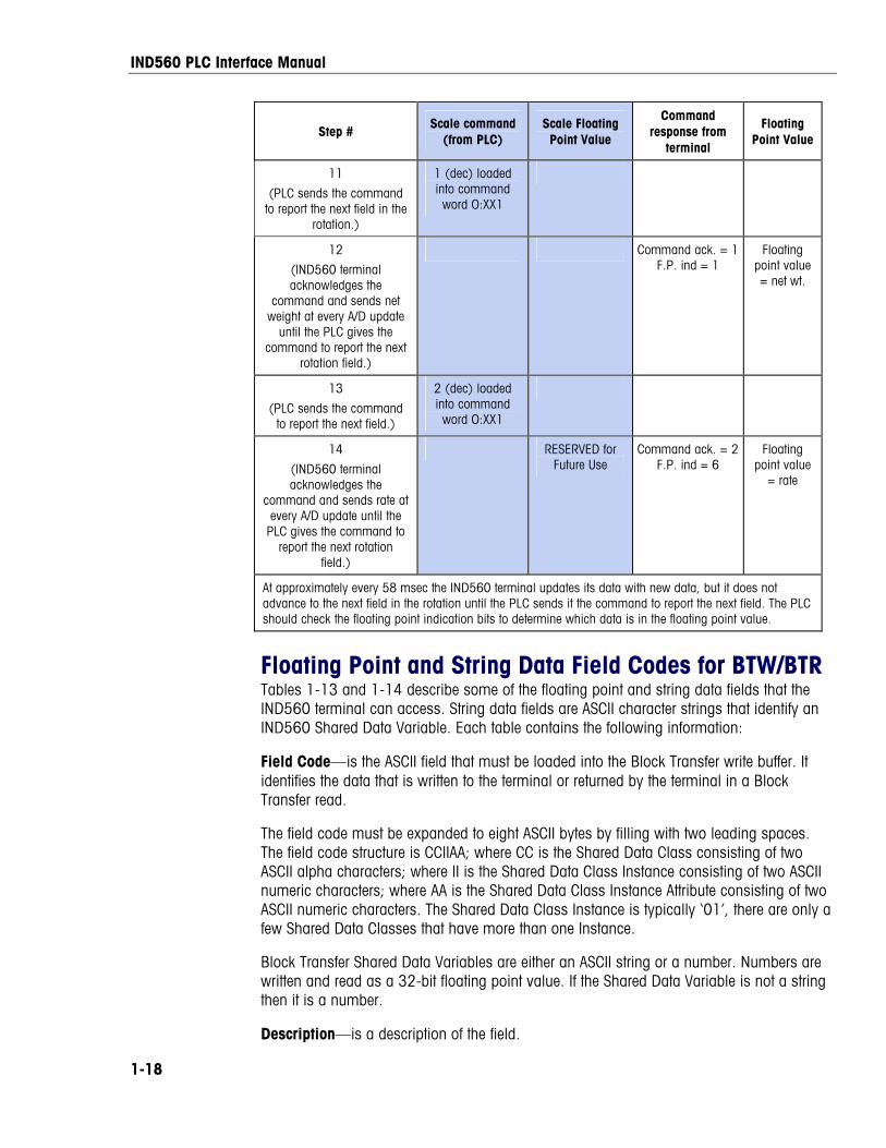
Table 1-12: Data Requirement: Rotation of Net Weight and Rate Updated on PLC Command
Step # Scale command
(from PLC) Scale Floating Point Value
Command response from
terminal
Floating Point Value
1 (PLC clears out any previous
rotation with reset)
3 (dec) loaded into command word O:XX1
2 (IND560 terminal sees new
command)
Command ack.= 1
F.P. ind = 30
3 (PLC adds net weight to
rotation)
41 (dec) loaded into command word O:XX1
(null value)
4 (IND560 terminal sees new
command)
Command ack. = 2
F.P. ind = 30
5 (PLC adds rate to the
rotation)
46 (dec) loaded into command word O:XX1
RESERVED for Future Use
6 (IND560 terminal sees new
command)
Command ack. = 3
F.P. ind = 30
(null value)
At this point, the rotation has been set up. Now the PLC needs send commands to the IND560 terminal to begin the rotation and advance to the next value when required.
7 (PLC sends the command to
report the first field in the rotation.)
1 (dec) loaded into command word O:XX1
8 (IND560 terminal
acknowledges the command and sends net weight at
every A/D update until the PLC gives the command to
report the next rotation field.)
Command ack. = 1
F.P. ind = 1
9 (PLC sends the command to report the next field.) Note: if the PLC leaves the 1 (dec)
in the command, the IND560 terminal does NOT
see this as another command to report the next
rotation field.
2 (dec) loaded into command word O:XX1
10 (IND560 terminal
acknowledges the command and sends rate at every A/D update until the PLC gives the command to report the
next rotation field.)
RESERVED for Future Use
Command ack. = 2
F.P. ind = 6
Floating point value
= rate
IND560 PLC Interface Manual
1-18
Step # Scale command
(from PLC) Scale Floating Point Value
Command response from
terminal
Floating Point Value
11
(PLC sends the command to report the next field in the
rotation.)
1 (dec) loaded into command word O:XX1
12
(IND560 terminal acknowledges the
command and sends net weight at every A/D update
until the PLC gives the command to report the next
rotation field.)
Command ack. = 1F.P. ind = 1
Floating point value = net wt.
13
(PLC sends the command to report the next field.)
2 (dec) loaded into command word O:XX1
14
(IND560 terminal acknowledges the
command and sends rate at every A/D update until the
PLC gives the command to report the next rotation
field.)
RESERVED for Future Use
Command ack. = 2F.P. ind = 6
Floating point value
= rate
At approximately every 58 msec the IND560 terminal updates its data with new data, but it does not advance to the next field in the rotation until the PLC sends it the command to report the next field. The PLC should check the floating point indication bits to determine which data is in the floating point value.
Floating Point and String Data Field Codes for BTW/BTR Tables 1-13 and 1-14 describe some of the floating point and string data fields that the IND560 terminal can access. String data fields are ASCII character strings that identify an IND560 Shared Data Variable. Each table contains the following information:
Field Code—is the ASCII field that must be loaded into the Block Transfer write buffer. It identifies the data that is written to the terminal or returned by the terminal in a Block Transfer read.
The field code must be expanded to eight ASCII bytes by filling with two leading spaces. The field code structure is CCIIAA; where CC is the Shared Data Class consisting of two ASCII alpha characters; where II is the Shared Data Class Instance consisting of two ASCII numeric characters; where AA is the Shared Data Class Instance Attribute consisting of two ASCII numeric characters. The Shared Data Class Instance is typically ‘01’, there are only a few Shared Data Classes that have more than one Instance.
Block Transfer Shared Data Variables are either an ASCII string or a number. Numbers are written and read as a 32-bit floating point value. If the Shared Data Variable is not a string then it is a number.
Description—is a description of the field.
IND560 PLC Interface Manual
1-19
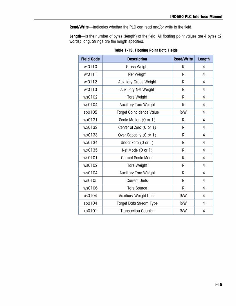
Read/Write—indicates whether the PLC can read and/or write to the field.
Length—is the number of bytes (length) of the field. All floating point values are 4 bytes (2 words) long. Strings are the length specified.
Table 1-13: Floating Point Data Fields
Field Code Description Read/Write Length
wt0110 Gross Weight R 4
wt0111 Net Weight R 4
wt0112 Auxiliary Gross Weight R 4
wt0113 Auxiliary Net Weight R 4
ws0102 Tare Weight R 4
ws0104 Auxiliary Tare Weight R 4
sp0105 Target Coincidence Value R/W 4
wx0131 Scale Motion (0 or 1) R 4
wx0132 Center of Zero (0 or 1) R 4
wx0133 Over Capacity (0 or 1) R 4
wx0134 Under Zero (0 or 1) R 4
wx0135 Net Mode (0 or 1) R 4
ws0101 Current Scale Mode R 4
ws0102 Tare Weight R 4
ws0104 Auxiliary Tare Weight R 4
ws0105 Current Units R 4
ws0106 Tare Source R 4
cs0104 Auxiliary Weight Units R/W 4
sp0104 Target Data Stream Type R/W 4
xp0101 Transaction Counter R/W 4
IND560 PLC Interface Manual
1-20
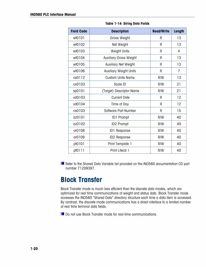
Table 1-14: String Data Fields
Field Code Description Read/Write Length
wt0101 Gross Weight R 13
wt0102 Net Weight R 13
wt0103 Weight Units R 4
wt0104 Auxiliary Gross Weight R 13
wt0105 Auxiliary Net Weight R 13
wt0106 Auxiliary Weight Units R 7
cs0112 Custom Units Name R/W 13
cs0103 Scale ID R/W 21
sp0101 (Target) Descriptor Name R/W 21
xd0103 Current Date R 12
xd0104 Time of Day R 12
cs0103 Software Part Number R 15
az0101 ID1 Prompt R/W 40
az0102 ID2 Prompt R/W 40
ar0108 ID1 Response R/W 40
ar0109 ID2 Response R/W 40
pt0101 Print Template 1 R/W 40
pt0111 Print Literal 1 R/W 40
Refer to the Shared Data Variable list provided on the IND560 documentation CD part number 71209397.
Block Transfer Block Transfer mode is much less efficient than the discrete data modes, which are optimized for real time communications of weight and status data. Block Transfer mode accesses the IND560 “Shared Data” directory structure each time a data item is accessed. By contrast, the discrete mode communications has a direct interface to a limited number of real time terminal data fields.
Do not use Block Transfer mode for real-time communications.
IND560 PLC Interface Manual
1-21
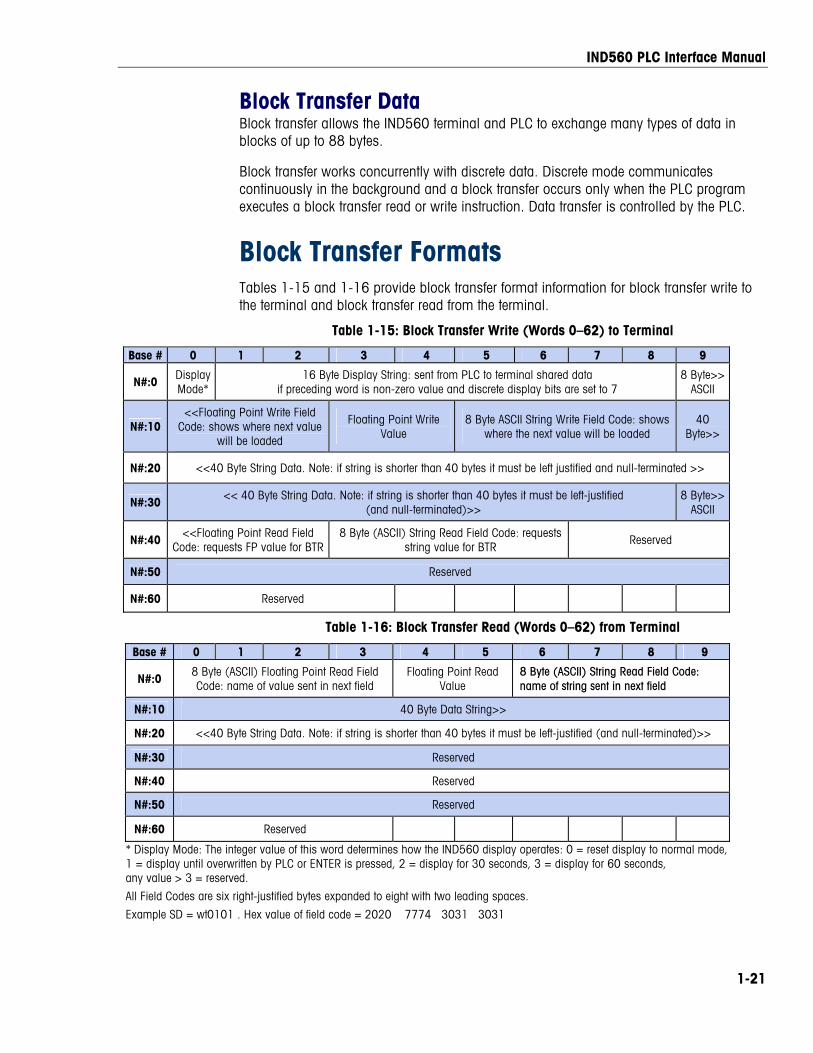
Block Transfer Data Block transfer allows the IND560 terminal and PLC to exchange many types of data in blocks of up to 88 bytes.
Block transfer works concurrently with discrete data. Discrete mode communicates continuously in the background and a block transfer occurs only when the PLC program executes a block transfer read or write instruction. Data transfer is controlled by the PLC.
Block Transfer Formats Tables 1-15 and 1-16 provide block transfer format information for block transfer write to the terminal and block transfer read from the terminal.
Table 1-15: Block Transfer Write (Words 0–62) to Terminal
Base # 0 1 2 3 4 5 6 7 8 9
N#:0 Display Mode*
16 Byte Display String: sent from PLC to terminal shared data if preceding word is non-zero value and discrete display bits are set to 7
8 Byte>> ASCII
N#:10 <<Floating Point Write Field
Code: shows where next value will be loaded
Floating Point Write Value
8 Byte ASCII String Write Field Code: shows where the next value will be loaded
40 Byte>>
N#:20 <<40 Byte String Data. Note: if string is shorter than 40 bytes it must be left justified and null-terminated >>
N#:30 << 40 Byte String Data. Note: if string is shorter than 40 bytes it must be left-justified (and null-terminated)>>
8 Byte>> ASCII
N#:40 <<Floating Point Read Field Code: requests FP value for BTR
8 Byte (ASCII) String Read Field Code: requests string value for BTR
Reserved
N#:50 Reserved
N#:60 Reserved
Table 1-16: Block Transfer Read (Words 0–62) from Terminal
Base # 0 1 2 3 4 5 6 7 8 9
N#:0 8 Byte (ASCII) Floating Point Read Field Code: name of value sent in next field
Floating Point Read Value
8 Byte (ASCII) String Read Field Code: name of string sent in next field
N#:10 40 Byte Data String>>
N#:20 <<40 Byte String Data. Note: if string is shorter than 40 bytes it must be left-justified (and null-terminated)>>
N#:30 Reserved
N#:40 Reserved
N#:50 Reserved
N#:60 Reserved
* Display Mode: The integer value of this word determines how the IND560 display operates: 0 = reset display to normal mode, 1 = display until overwritten by PLC or ENTER is pressed, 2 = display for 30 seconds, 3 = display for 60 seconds, any value > 3 = reserved.
All Field Codes are six right-justified bytes expanded to eight with two leading spaces.
Example SD = wt0101 . Hex value of field code = 2020 7774 3031 3031
IND560 PLC Interface Manual
1-22
Controlling the Discrete I/O Using a PLC Interface The IND560 terminal provides the ability to directly control its discrete outputs and read its discrete inputs via the (digital) PLC interface options. System integrators should be aware that the terminal’s discrete I/O updates are synchronized with the terminal’s A/D rate and not with the PLC I/O scan rate. This may cause a noticeable delay in reading inputs or updating outputs as observed from the PLC to real world signals. Consult the IND560 Terminal Technical Manual for discrete I/O wiring. Also note the outputs must be unassigned in the IND560 terminal setup.
Hardware Setup
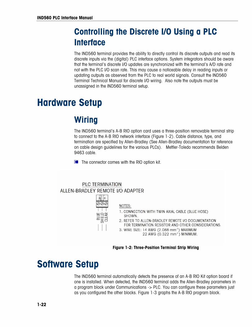
Wiring The IND560 terminal’s A-B RIO option card uses a three-position removable terminal strip to connect to the A-B RIO network interface (Figure 1-2). Cable distance, type, and termination are specified by Allen-Bradley (See Allen-Bradley documentation for reference on cable design guidelines for the various PLCs). Mettler-Toledo recommends Belden 9463 cable.
The connector comes with the RIO option kit.
Figure 1-2: Three-Position Terminal Strip Wiring
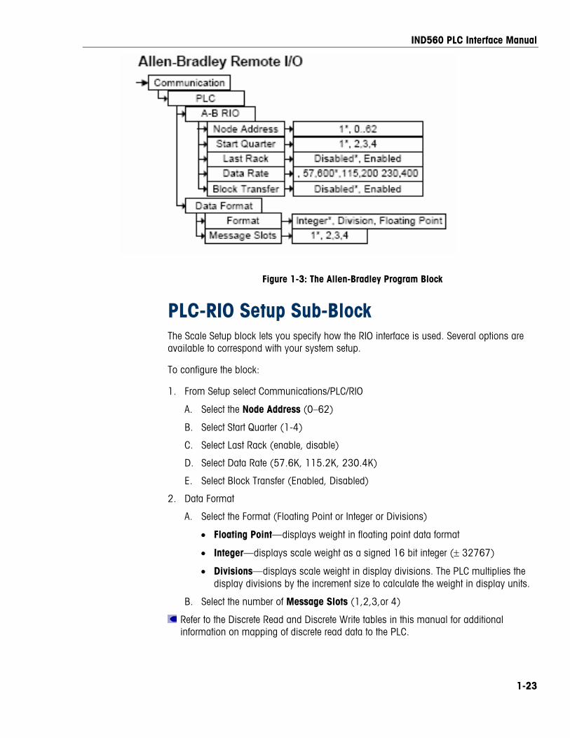
Software Setup The IND560 terminal automatically detects the presence of an A-B RIO Kit option board if one is installed. When detected, the IND560 terminal adds the Allen-Bradley parameters in a program block under Communications -> PLC. You can configure these parameters just as you configured the other blocks. Figure 1-3 graphs the A-B RIO program block.
IND560 PLC Interface Manual
1-23
Figure 1-3: The Allen-Bradley Program Block
PLC-RIO Setup Sub-Block The Scale Setup block lets you specify how the RIO interface is used. Several options are available to correspond with your system setup.
To configure the block:
1. From Setup select Communications/PLC/RIO
A. Select the Node Address (0–62)
B. Select Start Quarter (1-4)
C. Select Last Rack (enable, disable)
D. Select Data Rate (57.6K, 115.2K, 230.4K)
E. Select Block Transfer (Enabled, Disabled)
2. Data Format
A. Select the Format (Floating Point or Integer or Divisions)
• Floating Point—displays weight in floating point data format
• Integer—displays scale weight as a signed 16 bit integer (± 32767)
• Divisions—displays scale weight in display divisions. The PLC multiplies the display divisions by the increment size to calculate the weight in display units.
B. Select the number of Message Slots (1,2,3,or 4)
Refer to the Discrete Read and Discrete Write tables in this manual for additional information on mapping of discrete read data to the PLC.
IND560 PLC Interface Manual
1-24
Troubleshooting If the IND560 does not communicate with PLC do the following:
• Check wiring and network termination.
• Confirm that the IND560 settings match what are in the PLC as far as data type and rack assignment.
• Replace the RIO interface kit if the problem persists.
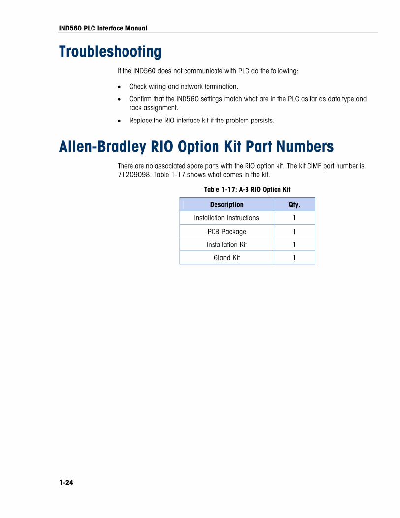
Allen-Bradley RIO Option Kit Part Numbers There are no associated spare parts with the RIO option kit. The kit CIMF part number is 71209098. Table 1-17 shows what comes in the kit.
Table 1-17: A-B RIO Option Kit
Description Qty.
Installation Instructions 1
PCB Package 1
Installation Kit 1
Gland Kit 1
IND560 PLC Interface Manual
1-25
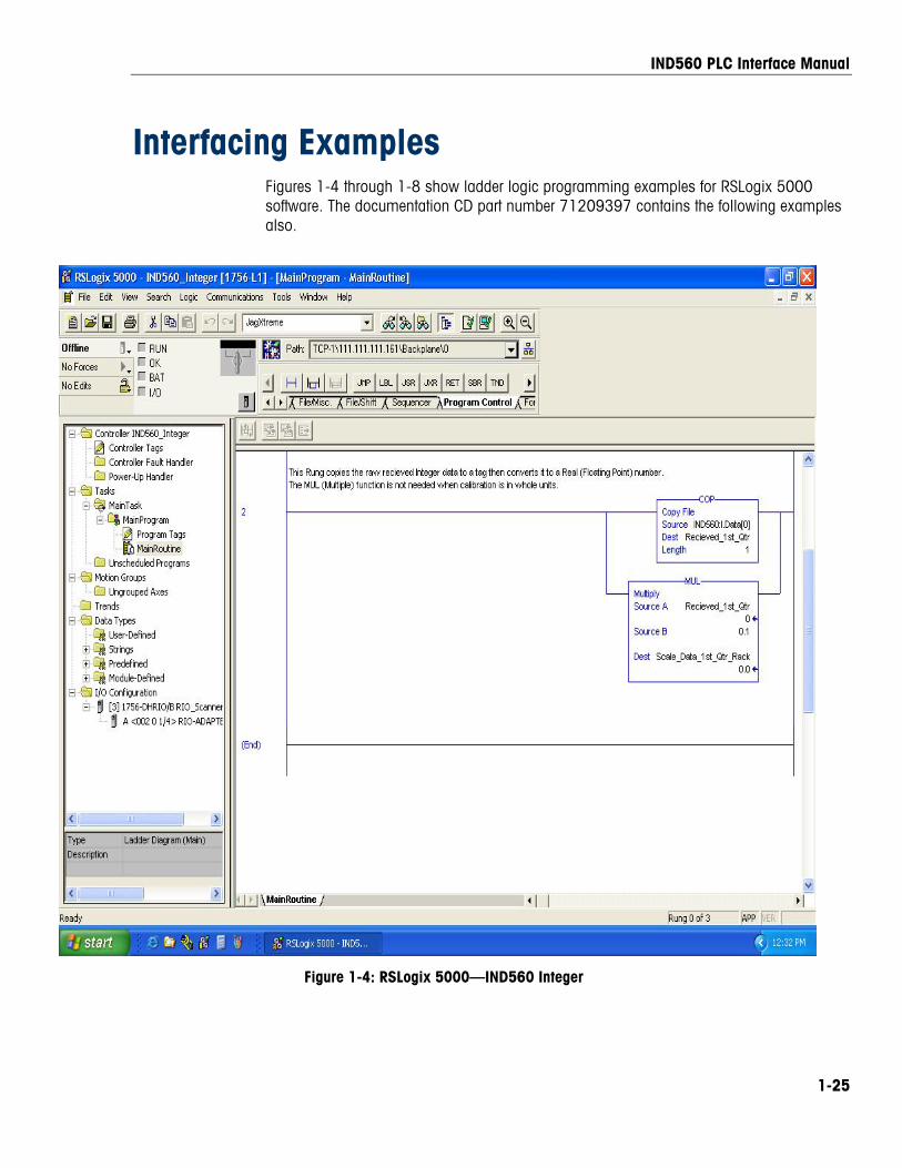
Interfacing Examples Figures 1-4 through 1-8 show ladder logic programming examples for RSLogix 5000 software. The documentation CD part number 71209397 contains the following examples also.
Figure 1-4: RSLogix 5000 – IND560 Integer
Figure 1-4: RSLogix 5000—IND560 Integer
IND560 PLC Interface Manual
1-26
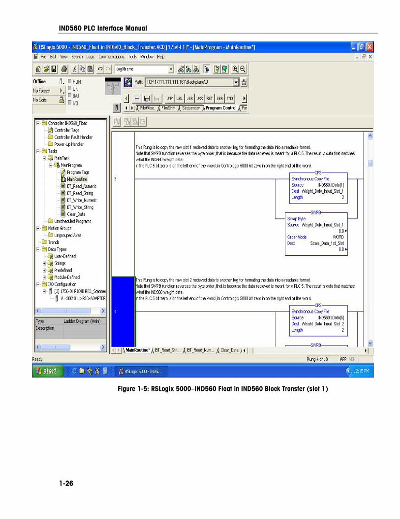
Figure 1-5: RSLogix 5000–IND560 Float in IND560 Block Transfer (slot 1)
IND560 PLC Interface Manual
1-27
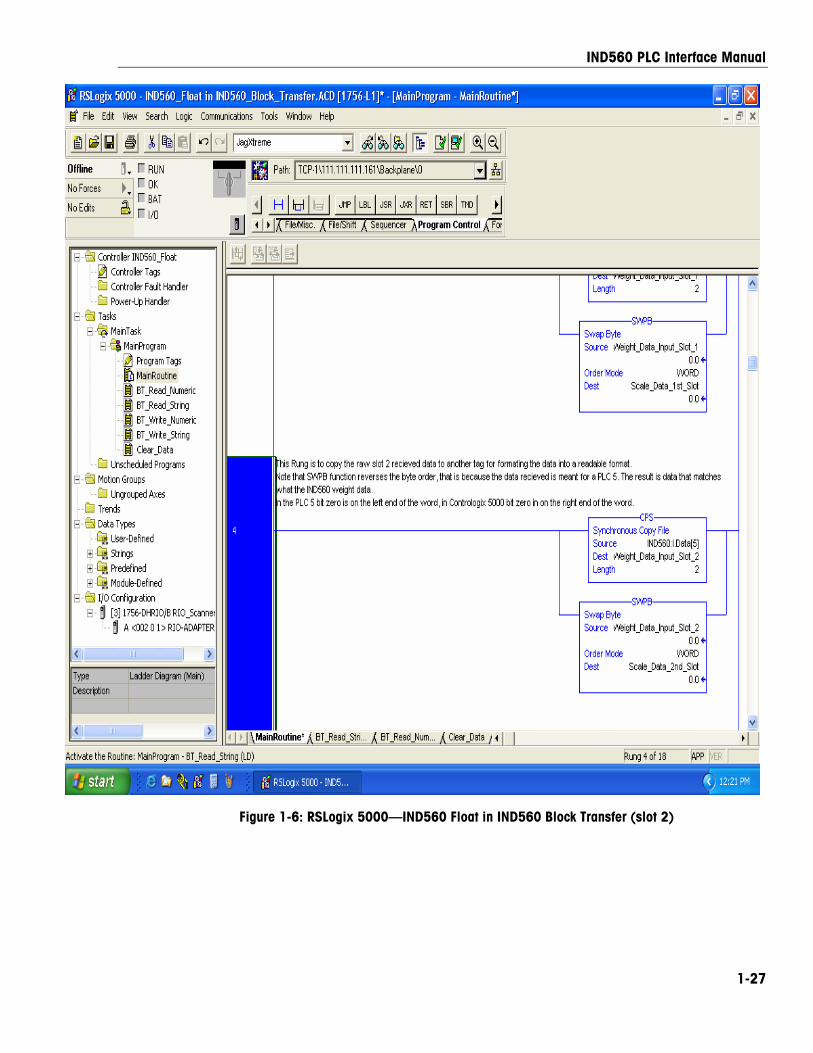
Figure 1-6: RSLogix 5000 – IND560 Float in IND560 Block Transfer (slot 2)
Figure 1-6: RSLogix 5000—IND560 Float in IND560 Block Transfer (slot 2)
IND560 PLC Interface Manual
1-28
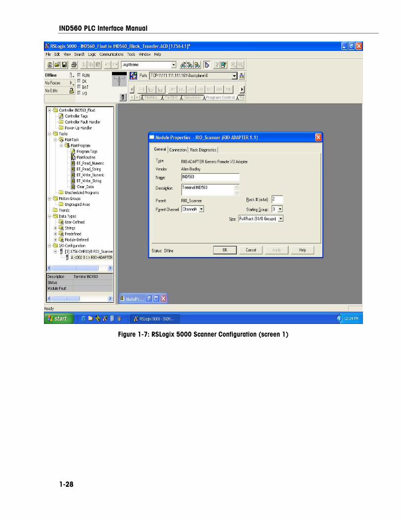
Figure 1-7: RSLogix 5000 Scanner Configuration (screen 1)
IND560 PLC Interface Manual
1-29
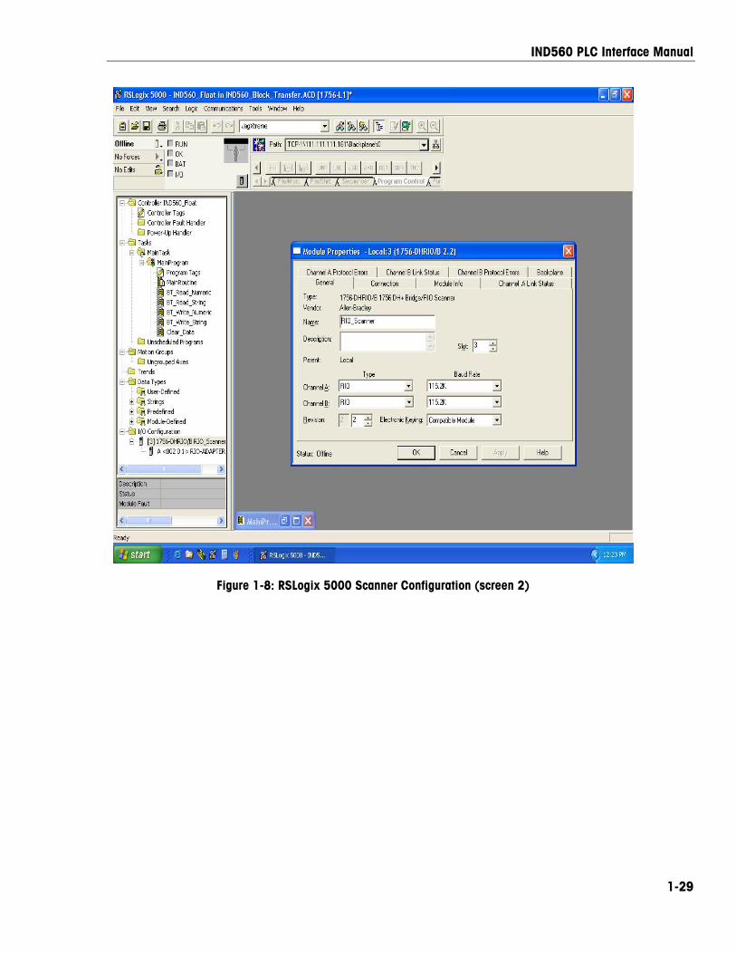
Figure 1-8: RSLogix 5000 Scanner Configuration (screen 2)

IND560 PLC Interface Manual
1-30
For your notes
2-1
Chapter 2.0 PROFIBUS Kit Option
Overview The PROFIBUS option card enables the IND560 terminal to communicate to a PROFIBUS L2-DP master according to DIN 19 245. It consists of an IND560 terminal backplane-compatible module and software that resides in the terminal, which implements the data exchange.
The PROFIBUS option card interfaces to programmable logic controllers (PLCs) such as Texas Instruments 505 series, Siemens S5 series, and Siemens S7 series PLCs. The PROFIBUS appears as a block of I/O on the PROFIBUS network. The size and mapping of the I/O is dependant on the setup of the PROFIBUS card at the IND560.
The data mapped within the I/O block is defined as Discrete or Shared Data Variables. Based upon the IND560 setup, discrete data is either Integer, Division, or Floating Point.
Discrete data is sent in groups defined as message blocks. The number of message blocks (1 to 4) is setup within the IND560. While the format of each message block is the same, the data received and displayed within a message block is dependant on the commands within the block.
The Texas Instruments (TI) 505 PLCs interface to the PROFIBUS via an I/O processor called a Field Interface Module (FIM). The FIM bus master recognizes a fixed set of PROFIBUS slave devices, all of which are viewed by it as some sort of remote I/O rack. On power up, the FIM queries each PROFIBUS slave node to determine which of the recognized types a device might be and configures itself accordingly. The PROFIBUS option appears to the FIM to be a small ET200U I/O rack.
The Siemens S5-115 series PLC also interfaces to the PROFIBUS using an I/O processor, an IM-308. This device must be locally programmed with the terminal interface type files. Newer Siemens S7 PLCs have the PROFIBUS option on their main controller card.
Communications PROFIBUS is based on a variety of existing national and international standards. The protocol architecture is based on the Open Systems Interconnection (OSI) reference model in accordance with the international standard ISO 7498.
IND560 PLC Interface Manual
2-2
The IND560 terminal supports the PROFIBUS-DP which is designed for high-speed data transfer at the sensor actuator level. (DP means Distributed Peripherals.) At this level, controllers such as PLCs exchange data via a fast serial link with their distributed peripherals. The data exchange with these distributed devices is mainly cyclic. The central controller (master) reads the input information from the slaves and sends the output information back to the slaves. It is important that the bus cycle time is shorter than the program cycle time of the controller, which is approximately 10 ms in most applications. The following is a summary of the technical features of the PROFIBUS-DP communications protocol:
Transmission Technique: PROFIBUS DIN 19 245 Part 1
• EIA RS 485 twisted pair cable or fiber optic
• 9.6 kbit/s up to 12 Mbit/s, max distance 200 m at 1.5 Mbit/s extendible with repeaters
• 12 megabaud maximum rate
Medium Access: Hybrid medium-access protocol according to DIN 19 245 Part 1
• Mono-Master or Multi-Master systems supported
• Master and Slave Devices, max 126 stations possible
Communications: Peer-to-Peer (user data transfer) or Multicast (synchronization)
• Cyclic Master-Slave user data transfer and acyclic Master-Master data transfer
Operation Modes:
• Operate: Cyclic transfer of input and output data
• Clear: Inputs are read and outputs are cleared
• Stop: Only master-master functions are possible
Synchronization: Enables synchronization of the inputs and/or outputs of all DP-Slaves
• Sync-Mode: Outputs are synchronized
• Freeze-Mode: Inputs are synchronized
Functionality:
• Cyclic user data transfer between DP-Master(s) and DP-Slave(s)
• Activation or deactivation of individual DP-Slaves
• Checking of the configuration of the DP-Slaves
• Powerful diagnosis mechanisms, three hierarchical levels of the diagnosis
• Synchronization of inputs and/or outputs
• Address assignment for the DP-Slaves over the bus
• Configuration of the DP-Master (DPM1) over the bus
• Maximum 246 byte input and output data per DP-Slave, typical 32 byte
IND560 PLC Interface Manual
2-3
Security and Protection Mechanisms:
• All messages are transmitted with Hamming Distance HD=4
• Watch-Dog Timer at the DP-Slaves
• Access protection for the inputs/outputs at the DP-Slaves
• Data transfer monitoring with configurable timer interval at the DP-Master (DPM1)
Device-Types:
• DP-Master Class 2 (DPM2) for example, programming/configuration device
• DP-Master Class 1 (DPM1) for example, central controller like PLC, CNC, or RC
• DP-Slave for example, Input/Output device with binary or analog inputs/outputs, drives
Cabling and Installation:
• Coupling or uncoupling of stations without affecting other stations
• Proven and easy to handle two conductor transmission technique
Node/Rack Address Each IND560 PROFIBUS option card represents one physical node. The node address is chosen by the system designer and then programmed into the IND560 and PLC. The IND560’s node address is programmed through the Setup/ Communications/PLC tree on the IND560 front panel. The node address and number of input and output words used to communicate between the terminal and the PLC are programmed into the PLC by using its PROFIBUS network configuration software and the IND560’s PROFIBUS GSD-type files.
The IND560 setup allows selection of the logical rack (node) address, data format (Integer/Floating Point/Divisions), the number of message slots assigned to the node, and the option of sending and receiving Shared Data. The number of input and output words required and the mapping of the I/O data is dependent on these selections.
The IND560 PROFIBUS GSD has a block of I/O defined for each of the 16 possible IND560 PROFIBUS combinations. The IND560 terminal will determine the number of input and output words needed for the number of configured message slots and chosen data format. The PLC must be configured for the same amount of space.
Data Formats The terminal’s PROFIBUS option card has two types of data exchanges: discrete data and shared data. The locations for each of these types of data are predefined by the IND560.
IND560 PLC Interface Manual
2-4
Each message slot selected to pass data through the terminal’s PROFIBUS option has its own assigned input and output words for continuous information to and from the PLC. Shared data access is only available when the Setup/ Communications/PLC/PROFIBUS Share Data option is Enabled. This data is used to pass information that cannot be sent in the discrete data because of size or process speed limitations. It uses additional input and output word space. The length of shared data value and data type is dependent on the type of shared data field requested. In no case does it exceed 10 words (20 bytes).
Data Integrity The terminal has specific bits to allow the PLC to confirm that the data was received without interrupt, and the scale is not in an error condition. It is important to monitor these bits. The PLC code must use them to confirm the integrity of the data received for the scale. Refer to the detailed data charts for specific information regarding the Data OK, update in progress, and data integrity bits and their usage.
Discrete Data There are three formats of discrete data available with the PROFIBUS option card: integer, division, and floating point.
The integer and division formats allow bi-directional communication of discrete bit encoded information or 16-bit binary word (signed integer) numerical values.
The floating-point format allows bi-directional communication of discrete bit-encoded information or numeric data encoded in IEEE 754, single-precision floating-point format.
The discrete data format affects the input/output word space required per message slot and the amount of input/output words used by the PROFIBUS option card.
Integer and division formats require two 16-bit words of input and two 16-bit words of output data per message slot. One slot uses two 16-bit words of input and two 16-bit words of output; two slots use four 16-bit words of input and four 16-bit words of output; three slots use six 16-bit words of input and six 16-bit words of output; and four slots use eight 16-bit words of input and eight 16-bit words of output.
The floating-point format requires more space per messages slot because floating point data uses two 16-bit words of data to represent the numeric data alone. The floating-point format requires four 16-bit words of input and four 16-bit words of output data per slot. Four scales using the floating-point format would use 16 words of input and 16 words of output data.
IND560 PLC Interface Manual
2-5
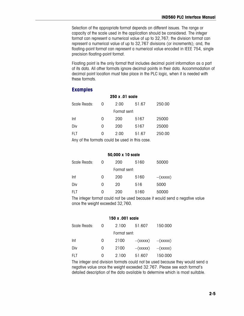
Selection of the appropriate format depends on different issues. The range or capacity of the scale used in the application should be considered. The integer format can represent a numerical value of up to 32,767; the division format can represent a numerical value of up to 32,767 divisions (or increments); and, the floating-point format can represent a numerical value encoded in IEEE 754, single precision floating-point format.
Floating point is the only format that includes decimal point information as a part of its data. All other formats ignore decimal points in their data. Accommodation of decimal point location must take place in the PLC logic, when it is needed with these formats.
Examples 250 x .01 scale
Scale Reads: 0 2.00 51.67 250.00
Format sent:
Int 0 200 5167 25000
Div 0 200 5167 25000
FLT 0 2.00 51.67 250.00
Any of the formats could be used in this case.
50,000 x 10 scale
Scale Reads: 0 200 5160 50000
Format sent:
Int 0 200 5160 −(xxxxx)
Div 0 20 516 5000
FLT 0 200 5160 50000
The integer format could not be used because it would send a negative value once the weight exceeded 32,760.
150 x .001 scale
Scale Reads: 0 2.100 51.607 150.000
Format sent:
Int 0 2100 −(xxxxx) −(xxxxx)
Div 0 2100 −(xxxxx) −(xxxxx)
FLT 0 2.100 51.607 150.000
The integer and division formats could not be used because they would send a negative value once the weight exceeded 32.767. Please see each format’s detailed description of the data available to determine which is most suitable.
IND560 PLC Interface Manual
2-6
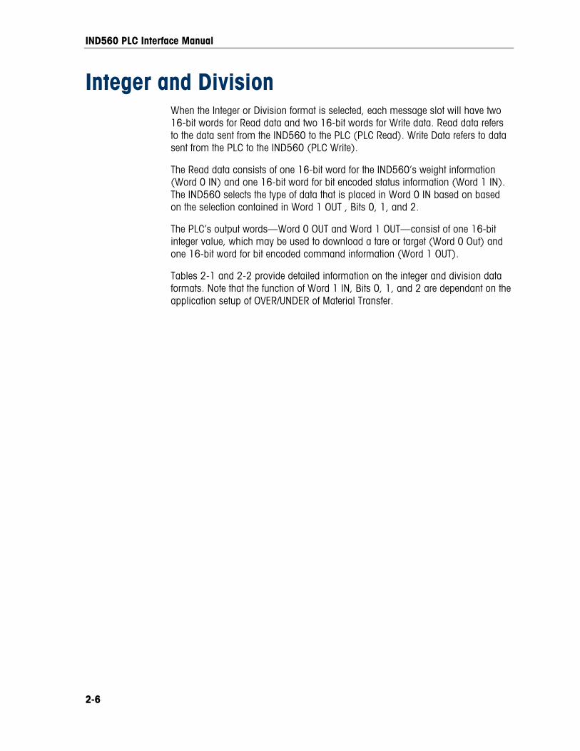
Integer and Division When the Integer or Division format is selected, each message slot will have two 16-bit words for Read data and two 16-bit words for Write data. Read data refers to the data sent from the IND560 to the PLC (PLC Read). Write Data refers to data sent from the PLC to the IND560 (PLC Write).
The Read data consists of one 16-bit word for the IND560’s weight information (Word 0 IN) and one 16-bit word for bit encoded status information (Word 1 IN). The IND560 selects the type of data that is placed in Word 0 IN based on based on the selection contained in Word 1 OUT , Bits 0, 1, and 2.
The PLC’s output words—Word 0 OUT and Word 1 OUT—consist of one 16-bit integer value, which may be used to download a tare or target (Word 0 Out) and one 16-bit word for bit encoded command information (Word 1 OUT).
Tables 2-1 and 2-2 provide detailed information on the integer and division data formats. Note that the function of Word 1 IN, Bits 0, 1, and 2 are dependant on the application setup of OVER/UNDER of Material Transfer.
IND560 PLC Interface Manual
2-7
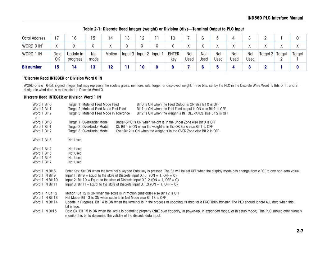
Table 2-1: Discrete Read Integer (weight) or Division (div)—Terminal Output to PLC Input
Octal Address 17 16 15 14 13 12 11 10 7 6 5 4 3 2 1 0
WORD 0 IN1 X X X X X X X X X X X X X X X X
WORD 1 IN Data OK
Update in progress
Net mode
Motion Input 3 Input 2 Input 1 ENTER
key Not
Used Not
UsedNot
Used Not
Used Not
Used Target 3 Target
2 Target
1
Bit number 15 14 13 12 11 10 9 8 7 6 5 4 3 2 1 0 1Discrete Read INTEGER or Division Word 0 IN
WORD 0 is a 16-bit, signed integer that may represent the scale’s gross, net, tare, rate, target, or displayed weight. Three bits, set by the PLC in the Discrete Write Word 1, Bits 0, 1, and 2, designate what data is represented in Discrete Word 0.
Discrete Read INTEGER or Division Word 1 IN
Word 1 Bit 0 Target 1: Material Feed Mode Feed Bit 0 is ON when the Feed Output is ON else Bit 0 is OFF Word 1 Bit 1 Target 2: Material Feed Mode Fast Feed Bit 1 is ON when the Fast Feed output is ON else Bit 1 is OFF Word 1 Bit 2 Target 3: Material Feed Mode In Tolerance Bit 2 is ON when the weight is IN TOLERANCE else Bit 2 is OFF or Word 1 Bit 0 Target 1: Over/Under Mode Under-Bit 0 is ON when weight is in the Under Zone else Bit 0 is OFF Word 1 Bit 1 Target 2: Over/Under Mode Ok-Bit 1 is ON when the weight is in the OK Zone else Bit 1 is OFF Word 1 Bit 2 Target 3: Over/Under Mode Over-Bit 2 is ON when the weight is in the OVER Zone else Bit 2 is OFF Word 1 Bit 3 Not Used Word 1 Bit 4 Not Used Word 1 Bit 5 Not Used Word 1 Bit 6 Not Used Word 1 Bit 7 Not Used Word 1 IN Bit 8 Enter Key: Set ON when the terminal’s keypad Enter key is pressed. The Bit will be set OFF when the display mode bits change from a “0” to any non-zero value. Word 1 IN Bit 9 Input 1: Bit 9 = Equal to the state of Discrete Input 0.1.1 (ON = 1, OFF = 0) Word 1 IN Bit 10 Input 2: Bit 10 = Equal to the state of Discrete Input 0.1.2 (ON = 1, OFF = 0) Word 1 IN Bit 11 Input 3: Bit 11= Equal to the state of Discrete Input 0.1.3 (ON = 1, OFF = 0) Word 1 In Bit 12 Motion: Bit 12 is ON when the scale is in motion (unstable) else Bit 12 is OFF Word 1 IN Bit 13 Net Mode: Bit 13 is ON when scale is in Net Mode else Bit 13 is OFF Word 1 IN Bit 14 Update In Progress: Bit 14 is ON when the terminal is in the process of updating its data for a PROFIBUS transfer. The PLC should ignore ALL data when this
bit is true. Word 1 IN Bit15 Data Ok: Bit 15 is ON when the scale is operating properly (NOT over capacity, in power-up, in expanded mode, or in setup mode). The PLC should continuously
monitor this bit to determine the validity of the discrete data input.
IND560 PLC Interface Manual
2-8
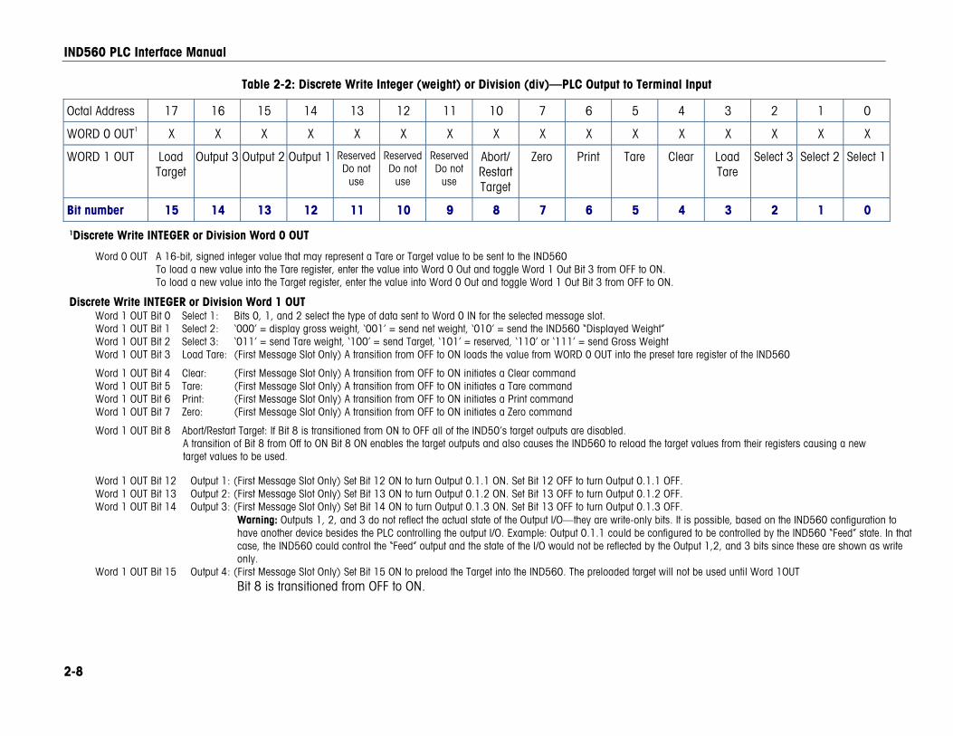
Table 2-2: Discrete Write Integer (weight) or Division (div)—PLC Output to Terminal Input
Octal Address 17 16 15 14 13 12 11 10 7 6 5 4 3 2 1 0
WORD 0 OUT1 X X X X X X X X X X X X X X X X
WORD 1 OUT Load Target
Output 3 Output 2 Output 1 ReservedDo not
use
ReservedDo not
use
ReservedDo not
use
Abort/Restart Target
Zero Print Tare Clear Load Tare
Select 3 Select 2 Select 1
Bit number 15 14 13 12 11 10 9 8 7 6 5 4 3 2 1 0
1Discrete Write INTEGER or Division Word 0 OUT
Word 0 OUT A 16-bit, signed integer value that may represent a Tare or Target value to be sent to the IND560 To load a new value into the Tare register, enter the value into Word 0 Out and toggle Word 1 Out Bit 3 from OFF to ON. To load a new value into the Target register, enter the value into Word 0 Out and toggle Word 1 Out Bit 3 from OFF to ON.
Discrete Write INTEGER or Division Word 1 OUT Word 1 OUT Bit 0 Select 1: Bits 0, 1, and 2 select the type of data sent to Word 0 IN for the selected message slot. Word 1 OUT Bit 1 Select 2: ‘000’ = display gross weight, ‘001’ = send net weight, ‘010’ = send the IND560 “Displayed Weight” Word 1 OUT Bit 2 Select 3: ‘011’ = send Tare weight, ‘100’ = send Target, ‘101’ = reserved, ‘110’ or ‘111’ = send Gross Weight Word 1 OUT Bit 3 Load Tare: (First Message Slot Only) A transition from OFF to ON loads the value from WORD 0 OUT into the preset tare register of the IND560
Word 1 OUT Bit 4 Clear: (First Message Slot Only) A transition from OFF to ON initiates a Clear command Word 1 OUT Bit 5 Tare: (First Message Slot Only) A transition from OFF to ON initiates a Tare command Word 1 OUT Bit 6 Print: (First Message Slot Only) A transition from OFF to ON initiates a Print command Word 1 OUT Bit 7 Zero: (First Message Slot Only) A transition from OFF to ON initiates a Zero command
Word 1 OUT Bit 8 Abort/Restart Target: If Bit 8 is transitioned from ON to OFF all of the IND50’s target outputs are disabled. A transition of Bit 8 from Off to ON Bit 8 ON enables the target outputs and also causes the IND560 to reload the target values from their registers causing a new target values to be used.
Word 1 OUT Bit 12 Output 1: (First Message Slot Only) Set Bit 12 ON to turn Output 0.1.1 ON. Set Bit 12 OFF to turn Output 0.1.1 OFF. Word 1 OUT Bit 13 Output 2: (First Message Slot Only) Set Bit 13 ON to turn Output 0.1.2 ON. Set Bit 13 OFF to turn Output 0.1.2 OFF. Word 1 OUT Bit 14 Output 3: (First Message Slot Only) Set Bit 14 ON to turn Output 0.1.3 ON. Set Bit 13 OFF to turn Output 0.1.3 OFF.
Warning: Outputs 1, 2, and 3 do not reflect the actual state of the Output I/O—they are write-only bits. It is possible, based on the IND560 configuration to have another device besides the PLC controlling the output I/O. Example: Output 0.1.1 could be configured to be controlled by the IND560 “Feed” state. In that case, the IND560 could control the “Feed” output and the state of the I/O would not be reflected by the Output 1,2, and 3 bits since these are shown as write only.
Word 1 OUT Bit 15 Output 4: (First Message Slot Only) Set Bit 15 ON to preload the Target into the IND560. The preloaded target will not be used until Word 1OUT Bit 8 is transitioned from OFF to ON.
IND560 PLC Interface Manual
2-9
Floating Point
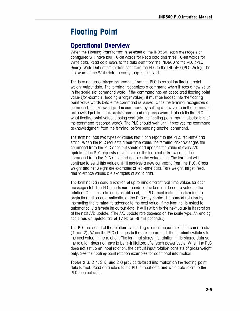
Operational Overview When the Floating Point format is selected at the IND560 ,each message slot configured will have four 16-bit words for Read data and three 16-bit words for Write data. Read data refers to the data sent from the IND560 to the PLC (PLC Read). Write Data refers to data sent from the PLC to the IND560 (PLC Write). The first word of the Write data memory map is reserved.
The terminal uses integer commands from the PLC to select the floating point weight output data. The terminal recognizes a command when it sees a new value in the scale slot command word. If the command has an associated floating point value (for example: loading a target value), it must be loaded into the floating point value words before the command is issued. Once the terminal recognizes a command, it acknowledges the command by setting a new value in the command acknowledge bits of the scale’s command response word. It also tells the PLC what floating point value is being sent (via the floating point input indicator bits of the command response word). The PLC should wait until it receives the command acknowledgment from the terminal before sending another command.
The terminal has two types of values that it can report to the PLC: real-time and static. When the PLC requests a real-time value, the terminal acknowledges the command from the PLC once but sends and updates the value at every A/D update. If the PLC requests a static value, the terminal acknowledges the command from the PLC once and updates the value once. The terminal will continue to send this value until it receives a new command from the PLC. Gross weight and net weight are examples of real-time data. Tare weight, target, feed, and tolerance values are examples of static data.
The terminal can send a rotation of up to nine different real-time values for each message slot. The PLC sends commands to the terminal to add a value to the rotation. Once the rotation is established, the PLC must instruct the terminal to begin its rotation automatically, or the PLC may control the pace of rotation by instructing the terminal to advance to the next value. If the terminal is asked to automatically alternate its output data, it will switch to the next value in its rotation at the next A/D update. (The A/D update rate depends on the scale type. An analog scale has an update rate of 17 Hz or 58 milliseconds.)
The PLC may control the rotation by sending alternate report next field commands (1 and 2). When the PLC changes to the next command, the terminal switches to the next value in the rotation. The terminal stores the rotation in its shared data so the rotation does not have to be re-initialized after each power cycle. When the PLC does not set up an input rotation, the default input rotation consists of gross weight only. See the floating-point rotation examples for additional information.
Tables 2-3, 2-4, 2-5, and 2-6 provide detailed information on the floating-point data format. Read data refers to the PLC’s input data and write data refers to the PLC’s output data.
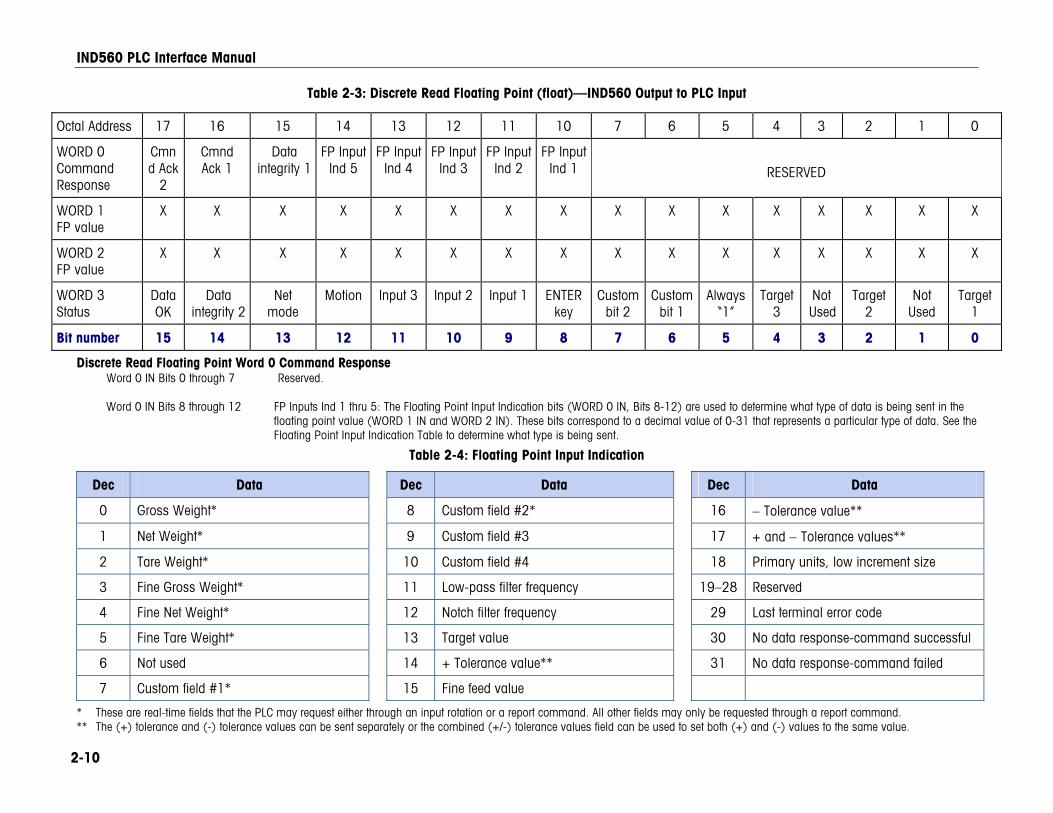
IND560 PLC Interface Manual
2-10
Table 2-3: Discrete Read Floating Point (float)—IND560 Output to PLC Input
Octal Address 17 16 15 14 13 12 11 10 7 6 5 4 3 2 1 0
WORD 0 Command Response
Cmnd Ack
2
Cmnd Ack 1
Data integrity 1
FP Input Ind 5
FP Input Ind 4
FP Input Ind 3
FP Input Ind 2
FP Input Ind 1
RESERVED
WORD 1 FP value
X X X X X X X X X X X X X X X X
WORD 2 FP value
X X X X X X X X X X X X X X X X
WORD 3 Status
Data OK
Data integrity 2
Net mode
Motion Input 3 Input 2 Input 1 ENTER key
Custom bit 2
Custom bit 1
Always“1”
Target3
Not Used
Target2
Not Used
Target 1
Bit number 15 14 13 12 11 10 9 8 7 6 5 4 3 2 1 0
Discrete Read Floating Point Word 0 Command Response Word 0 IN Bits 0 through 7 Reserved. Word 0 IN Bits 8 through 12 FP Inputs Ind 1 thru 5: The Floating Point Input Indication bits (WORD 0 IN, Bits 8-12) are used to determine what type of data is being sent in the
floating point value (WORD 1 IN and WORD 2 IN). These bits correspond to a decimal value of 0-31 that represents a particular type of data. See the Floating Point Input Indication Table to determine what type is being sent.
Table 2-4: Floating Point Input Indication
Dec Data Dec Data Dec Data
0 Gross Weight* 8 Custom field #2* 16 − Tolerance value**
1 Net Weight* 9 Custom field #3 17 + and − Tolerance values**
2 Tare Weight* 10 Custom field #4 18 Primary units, low increment size
3 Fine Gross Weight* 11 Low-pass filter frequency 19–28 Reserved
4 Fine Net Weight* 12 Notch filter frequency 29 Last terminal error code
5 Fine Tare Weight* 13 Target value 30 No data response-command successful
6 Not used 14 + Tolerance value** 31 No data response-command failed
7 Custom field #1* 15 Fine feed value
* These are real-time fields that the PLC may request either through an input rotation or a report command. All other fields may only be requested through a report command. ** The (+) tolerance and (-) tolerance values can be sent separately or the combined (+/-) tolerance values field can be used to set both (+) and (-) values to the same value.
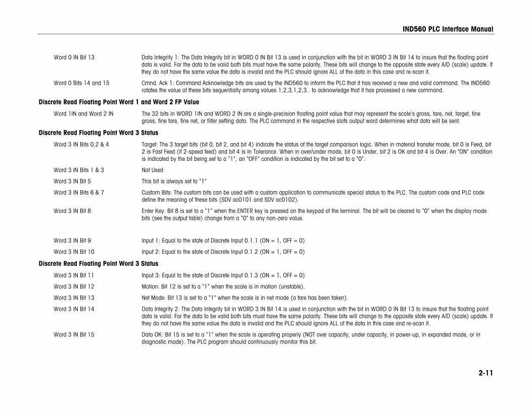
IND560 PLC Interface Manual
2-11
Word 0 IN Bit 13 Data Integrity 1: The Data Integrity bit in WORD 0 IN Bit 13 is used in conjunction with the bit in WORD 3 IN Bit 14 to insure that the floating point data is valid. For the data to be valid both bits must have the same polarity. These bits will change to the opposite state every A/D (scale) update. If they do not have the same value the data is invalid and the PLC should ignore ALL of the data in this case and re-scan it.
Word 0 Bits 14 and 15 Cmnd. Ack 1: Command Acknowledge bits are used by the IND560 to inform the PLC that it has received a new and valid command. The IND560 rotates the value of these bits sequentially among values 1,2,3,1,2,3.. to acknowledge that it has processed a new command.
Discrete Read Floating Point Word 1 and Word 2 FP Value
Word 1IN and Word 2 IN The 32 bits in WORD 1IN and WORD 2 IN are a single-precision floating point value that may represent the scale’s gross, tare, net, target, fine gross, fine tare, fine net, or filter setting data. The PLC command in the respective slots output word determines what data will be sent.
Discrete Read Floating Point Word 3 Status
Word 3 IN Bits 0,2 & 4 Target: The 3 target bits (bit 0, bit 2, and bit 4) indicate the status of the target comparison logic. When in material transfer mode, bit 0 is Feed, bit 2 is Fast Feed (if 2-speed feed) and bit 4 is In Tolerance. When in over/under mode, bit 0 is Under, bit 2 is OK and bit 4 is Over. An “ON” condition is indicated by the bit being set to a “1”, an “OFF” condition is indicated by the bit set to a “0”.
Word 3 IN Bits 1 & 3 Not Used
Word 3 IN Bit 5 This bit is always set to “1”
Word 3 IN Bits 6 & 7 Custom Bits: The custom bits can be used with a custom application to communicate special status to the PLC. The custom code and PLC code define the meaning of these bits (SDV ac0101 and SDV ac0102).
Word 3 IN Bit 8 Enter Key: Bit 8 is set to a “1” when the ENTER key is pressed on the keypad of the terminal. The bit will be cleared to “0” when the display mode bits (see the output table) change from a “0” to any non-zero value.
Word 3 IN Bit 9 Input 1: Equal to the state of Discrete Input 0.1.1 (ON = 1, OFF = 0)
Word 3 IN Bit 10 Input 2: Equal to the state of Discrete Input 0.1.2 (ON = 1, OFF = 0)
Discrete Read Floating Point Word 3 Status
Word 3 IN Bit 11 Input 3: Equal to the state of Discrete Input 0.1.3 (ON = 1, OFF = 0)
Word 3 IN Bit 12 Motion: Bit 12 is set to a “1” when the scale is in motion (unstable).
Word 3 IN Bit 13 Net Mode: Bit 13 is set to a “1” when the scale is in net mode (a tare has been taken).
Word 3 IN Bit 14 Data Integrity 2: The Data Integrity bit in WORD 3 IN Bit 14 is used in conjunction with the bit in WORD 0 IN Bit 13 to insure that the floating point data is valid. For the data to be valid both bits must have the same polarity. These bits will change to the opposite state every A/D (scale) update. If they do not have the same value the data is invalid and the PLC should ignore ALL of the data in this case and re-scan it.
Word 3 IN Bit 15 Data OK: Bit 15 is set to a “1” when the scale is operating properly (NOT over capacity, under capacity, in power-up, in expanded mode, or in diagnostic mode). The PLC program should continuously monitor this bit.
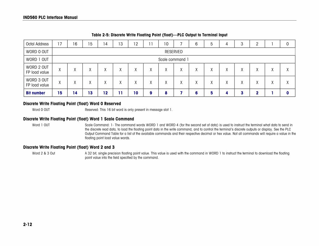
IND560 PLC Interface Manual
2-12
Table 2-5: Discrete Write Floating Point (float)—PLC Output to Terminal Input
Octal Address 17 16 15 14 13 12 11 10 7 6 5 4 3 2 1 0
WORD 0 OUT RESERVED
WORD 1 OUT Scale command 1
WORD 2 OUT FP load value
X X X X X X X X X X X X X X X X
WORD 3 OUT FP load value X X X X X X X X X X X X X X X X
Bit number 15 14 13 12 11 10 9 8 7 6 5 4 3 2 1 0
Discrete Write Floating Point (float) Word 0 Reserved Word 0 OUT Reserved: This 16 bit word is only present in message slot 1.
Discrete Write Floating Point (float) Word 1 Scale Command Word 1 OUT Scale Command: 1- The command words WORD 1 and WORD 4 (for the second set of data) is used to instruct the terminal what data to send in
the discrete read data, to load the floating point data in the write command, and to control the terminal’s discrete outputs or display. See the PLC Output Command Table for a list of the available commands and their respective decimal or hex value. Not all commands will require a value in the floating point load value words.
Discrete Write Floating Point (float) Word 2 and 3 Word 2 & 3 Out A 32 bit, single precision floating point value. This value is used with the command in WORD 1 to instruct the terminal to download the floating
point value into the field specified by the command.
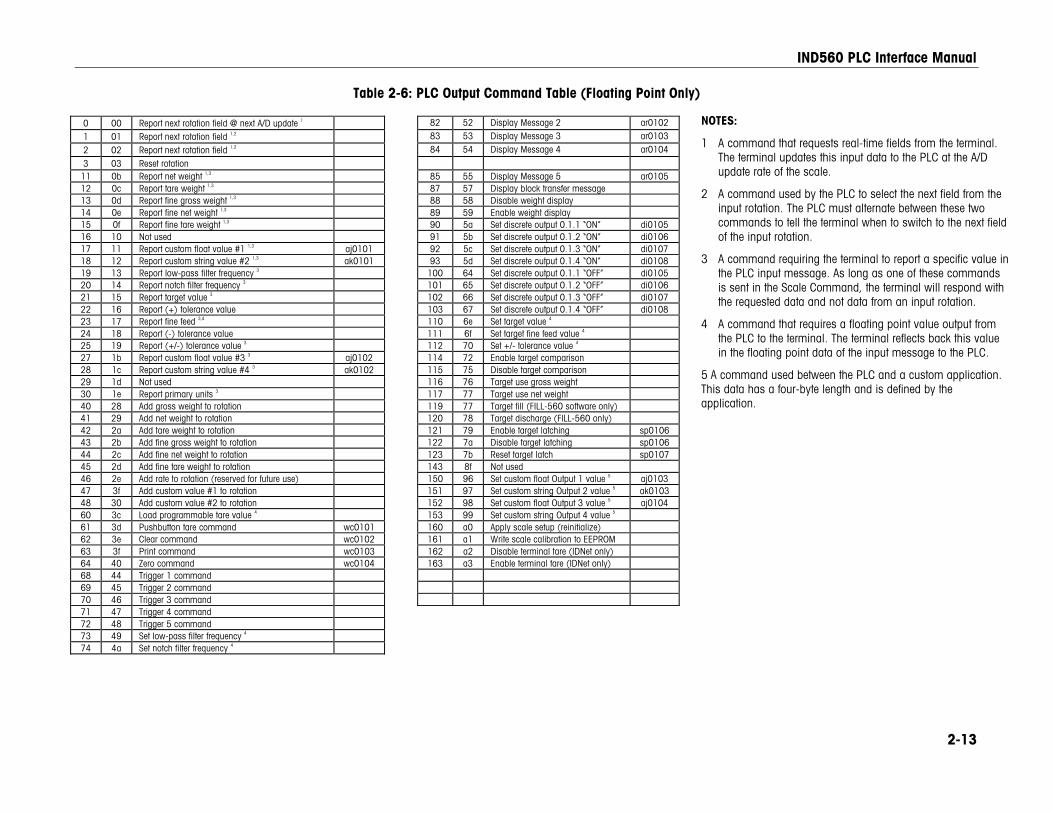
IND560 PLC Interface Manual
2-13
Table 2-6: PLC Output Command Table (Floating Point Only)
0 00 Report next rotation field @ next A/D update 1 82 52 Display Message 2 ar0102
1 01 Report next rotation field 1,2 83 53 Display Message 3 ar0103
2 02 Report next rotation field 1,2 84 54 Display Message 4 ar0104
3 03 Reset rotation 11 0b Report net weight 1,3 85 55 Display Message 5 ar0105 12 0c Report tare weight 1,3 87 57 Display block transfer message 13 0d Report fine gross weight 1,3 88 58 Disable weight display 14 0e Report fine net weight 1,3 89 59 Enable weight display 15 0f Report fine tare weight 1,3 90 5a Set discrete output 0.1.1 “ON” di0105 16 10 Not used 91 5b Set discrete output 0.1.2 “ON” di0106 17 11 Report custom float value #1 1,3 aj0101 92 5c Set discrete output 0.1.3 “ON” di0107 18 12 Report custom string value #2 1,3 ak0101 93 5d Set discrete output 0.1.4 “ON” di0108 19 13 Report low-pass filter frequency 3 100 64 Set discrete output 0.1.1 “OFF” di0105 20 14 Report notch filter frequency 3 101 65 Set discrete output 0.1.2 “OFF” di0106 21 15 Report target value 3 102 66 Set discrete output 0.1.3 “OFF” di0107 22 16 Report (+) tolerance value 103 67 Set discrete output 0.1.4 “OFF” di0108 23 17 Report fine feed 3,4 110 6e Set target value 4 24 18 Report (-) tolerance value 111 6f Set target fine feed value 4 25 19 Report (+/-) tolerance value 3 112 70 Set +/- tolerance value 4 27 1b Report custom float value #3 3 aj0102 114 72 Enable target comparison 28 1c Report custom string value #4 3 ak0102 115 75 Disable target comparison 29 1d Not used 116 76 Target use gross weight 30 1e Report primary units 3 117 77 Target use net weight 40 28 Add gross weight to rotation 119 77 Target fill (FILL-560 software only) 41 29 Add net weight to rotation 120 78 Target discharge (FILL-560 only) 42 2a Add tare weight to rotation 121 79 Enable target latching sp0106 43 2b Add fine gross weight to rotation 122 7a Disable target latching sp0106 44 2c Add fine net weight to rotation 123 7b Reset target latch sp0107 45 2d Add fine tare weight to rotation 143 8f Not used 46 2e Add rate to rotation (reserved for future use) 150 96 Set custom float Output 1 value 5 aj0103 47 3f Add custom value #1 to rotation 151 97 Set custom string Output 2 value 5 ak0103 48 30 Add custom value #2 to rotation 152 98 Set custom float Output 3 value 5 aj0104 60 3c Load programmable tare value 4 153 99 Set custom string Output 4 value 5 61 3d Pushbutton tare command wc0101 160 a0 Apply scale setup (reinitialize) 62 3e Clear command wc0102 161 a1 Write scale calibration to EEPROM 63 3f Print command wc0103 162 a2 Disable terminal tare (IDNet only) 64 40 Zero command wc0104 163 a3 Enable terminal tare (IDNet only) 68 44 Trigger 1 command 69 45 Trigger 2 command 70 46 Trigger 3 command 71 47 Trigger 4 command 72 48 Trigger 5 command 73 49 Set low-pass filter frequency 4 74 4a Set notch filter frequency 4
NOTES:
1 A command that requests real-time fields from the terminal. The terminal updates this input data to the PLC at the A/D update rate of the scale.
2 A command used by the PLC to select the next field from the input rotation. The PLC must alternate between these two commands to tell the terminal when to switch to the next field of the input rotation.
3 A command requiring the terminal to report a specific value in the PLC input message. As long as one of these commands is sent in the Scale Command, the terminal will respond with the requested data and not data from an input rotation.
4 A command that requires a floating point value output from the PLC to the terminal. The terminal reflects back this value in the floating point data of the input message to the PLC.
5 A command used between the PLC and a custom application. This data has a four-byte length and is defined by the application.
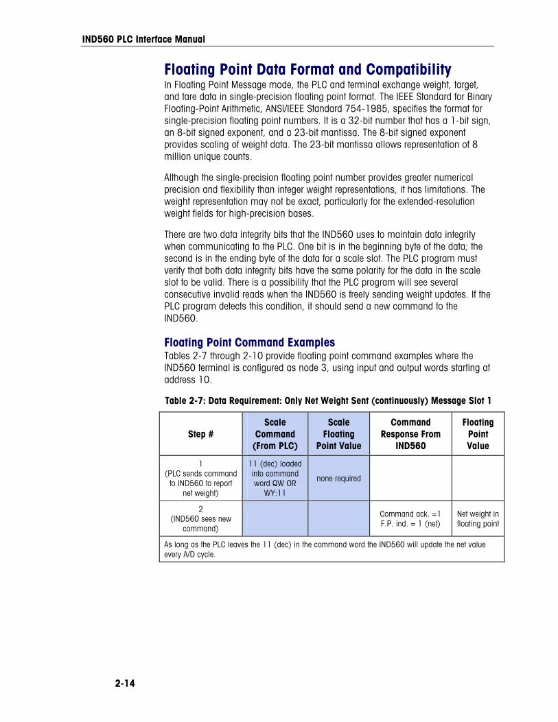
IND560 PLC Interface Manual
2-14
Floating Point Data Format and Compatibility In Floating Point Message mode, the PLC and terminal exchange weight, target, and tare data in single-precision floating point format. The IEEE Standard for Binary Floating-Point Arithmetic, ANSI/IEEE Standard 754-1985, specifies the format for single-precision floating point numbers. It is a 32-bit number that has a 1-bit sign, an 8-bit signed exponent, and a 23-bit mantissa. The 8-bit signed exponent provides scaling of weight data. The 23-bit mantissa allows representation of 8 million unique counts.
Although the single-precision floating point number provides greater numerical precision and flexibility than integer weight representations, it has limitations. The weight representation may not be exact, particularly for the extended-resolution weight fields for high-precision bases.
There are two data integrity bits that the IND560 uses to maintain data integrity when communicating to the PLC. One bit is in the beginning byte of the data; the second is in the ending byte of the data for a scale slot. The PLC program must verify that both data integrity bits have the same polarity for the data in the scale slot to be valid. There is a possibility that the PLC program will see several consecutive invalid reads when the IND560 is freely sending weight updates. If the PLC program detects this condition, it should send a new command to the IND560.
Floating Point Command Examples Tables 2-7 through 2-10 provide floating point command examples where the IND560 terminal is configured as node 3, using input and output words starting at address 10.
Table 2-7: Data Requirement: Only Net Weight Sent (continuously) Message Slot 1
Step # Scale
Command (From PLC)
Scale Floating
Point Value
Command Response From
IND560
Floating Point Value
1 (PLC sends command
to IND560 to report net weight)
11 (dec) loaded into command word QW OR
WY:11
none required
2 (IND560 sees new
command) Command ack. =1
F.P. ind. = 1 (net) Net weight in floating point
As long as the PLC leaves the 11 (dec) in the command word the IND560 will update the net value every A/D cycle.
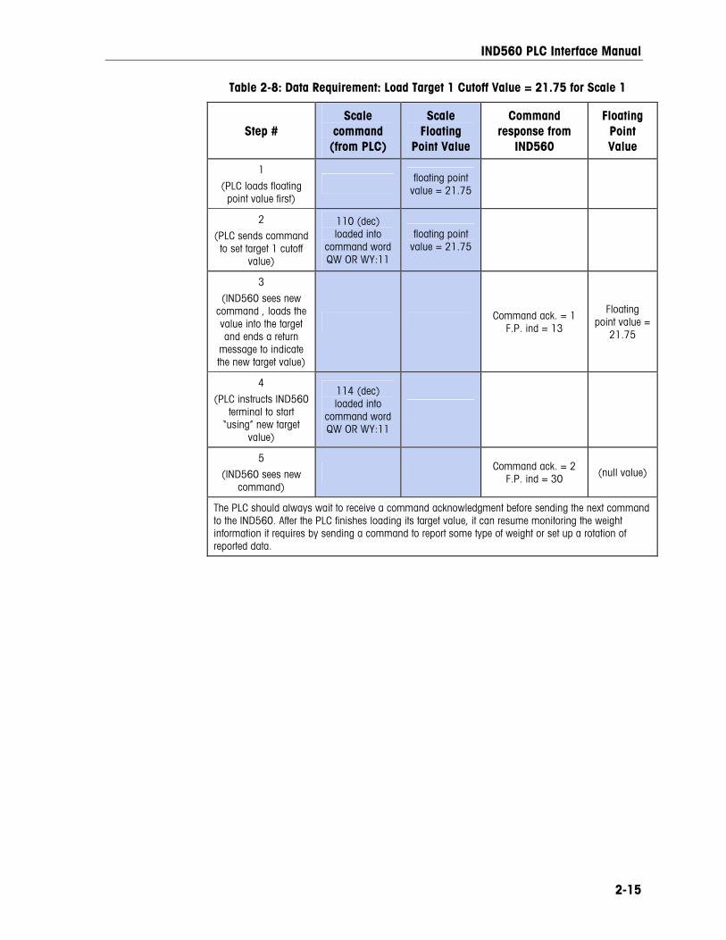
IND560 PLC Interface Manual
2-15
Table 2-8: Data Requirement: Load Target 1 Cutoff Value = 21.75 for Scale 1
Step # Scale
command (from PLC)
Scale Floating
Point Value
Command response from
IND560
Floating Point Value
1
(PLC loads floating point value first)
floating point value = 21.75
2
(PLC sends command to set target 1 cutoff
value)
110 (dec) loaded into
command word QW OR WY:11
floating point value = 21.75
3
(IND560 sees new command , loads the value into the target and ends a return
message to indicate the new target value)
Command ack. = 1 F.P. ind = 13
Floating point value =
21.75
4
(PLC instructs IND560 terminal to start
“using” new target value)
114 (dec) loaded into
command word QW OR WY:11
5
(IND560 sees new command)
Command ack. = 2 F.P. ind = 30 (null value)
The PLC should always wait to receive a command acknowledgment before sending the next command to the IND560. After the PLC finishes loading its target value, it can resume monitoring the weight information it requires by sending a command to report some type of weight or set up a rotation of reported data.
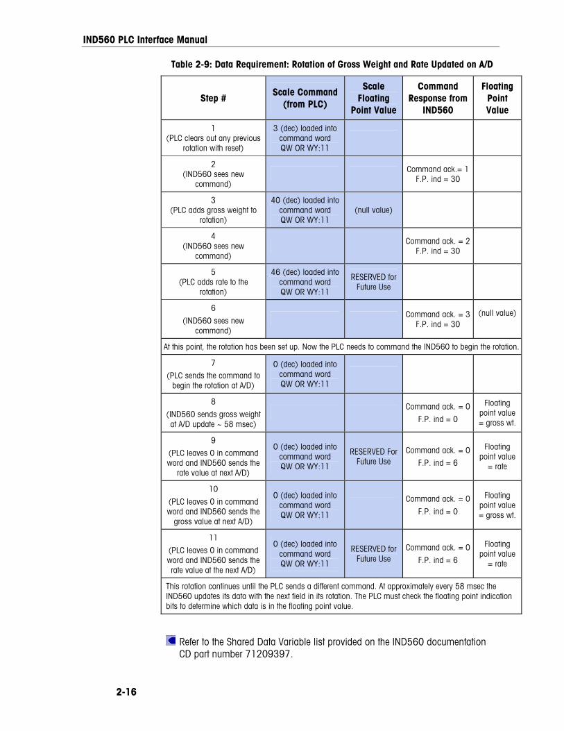
IND560 PLC Interface Manual
2-16
Table 2-9: Data Requirement: Rotation of Gross Weight and Rate Updated on A/D
Step # Scale Command
(from PLC)
Scale Floating
Point Value
Command Response from
IND560
Floating Point Value
1 (PLC clears out any previous
rotation with reset)
3 (dec) loaded into command word QW OR WY:11
2 (IND560 sees new
command) Command ack.= 1
F.P. ind = 30
3 (PLC adds gross weight to
rotation)
40 (dec) loaded into command word QW OR WY:11
(null value)
4 (IND560 sees new
command) Command ack. = 2
F.P. ind = 30
5 (PLC adds rate to the
rotation)
46 (dec) loaded into command word QW OR WY:11
RESERVED for Future Use
6
(IND560 sees new command)
Command ack. = 3F.P. ind = 30
(null value)
At this point, the rotation has been set up. Now the PLC needs to command the IND560 to begin the rotation.
7
(PLC sends the command to begin the rotation at A/D)
0 (dec) loaded into command word QW OR WY:11
8
(IND560 sends gross weight at A/D update ~ 58 msec)
Command ack. = 0
F.P. ind = 0
Floating point value = gross wt.
9
(PLC leaves 0 in command word and IND560 sends the
rate value at next A/D)
0 (dec) loaded into command word QW OR WY:11
RESERVED For Future Use
Command ack. = 0
F.P. ind = 6
Floating point value
= rate
10
(PLC leaves 0 in command word and IND560 sends the
gross value at next A/D)
0 (dec) loaded into command word QW OR WY:11
Command ack. = 0
F.P. ind = 0
Floating point value = gross wt.
11
(PLC leaves 0 in command word and IND560 sends the rate value at the next A/D)
0 (dec) loaded into command word QW OR WY:11
RESERVED for Future Use
Command ack. = 0
F.P. ind = 6
Floating point value
= rate
This rotation continues until the PLC sends a different command. At approximately every 58 msec the IND560 updates its data with the next field in its rotation. The PLC must check the floating point indication bits to determine which data is in the floating point value.
Refer to the Shared Data Variable list provided on the IND560 documentation CD part number 71209397.
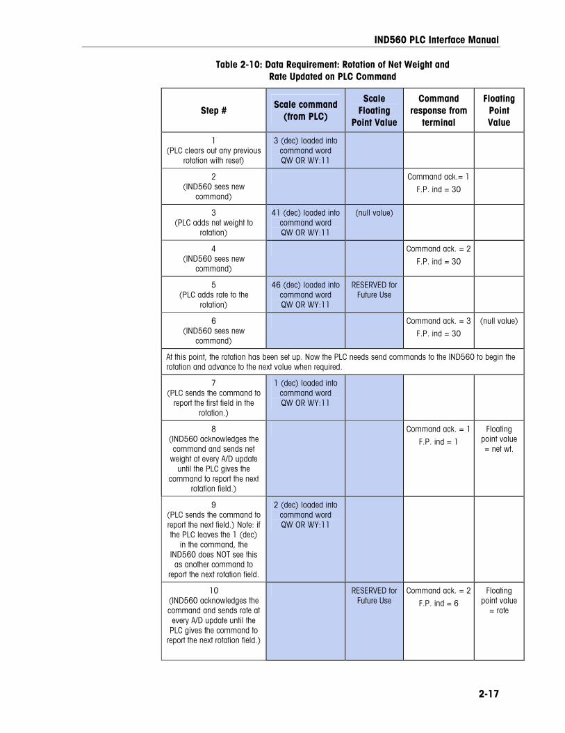
IND560 PLC Interface Manual
2-17
Table 2-10: Data Requirement: Rotation of Net Weight and Rate Updated on PLC Command
Step # Scale command
(from PLC)
Scale Floating
Point Value
Command response from
terminal
Floating Point Value
1 (PLC clears out any previous
rotation with reset)
3 (dec) loaded into command word QW OR WY:11
2 (IND560 sees new
command)
Command ack.= 1
F.P. ind = 30
3 (PLC adds net weight to
rotation)
41 (dec) loaded into command word QW OR WY:11
(null value)
4 (IND560 sees new
command)
Command ack. = 2
F.P. ind = 30
5 (PLC adds rate to the
rotation)
46 (dec) loaded into command word QW OR WY:11
RESERVED for Future Use
6 (IND560 sees new
command)
Command ack. = 3
F.P. ind = 30
(null value)
At this point, the rotation has been set up. Now the PLC needs send commands to the IND560 to begin the rotation and advance to the next value when required.
7 (PLC sends the command to
report the first field in the rotation.)
1 (dec) loaded into command word QW OR WY:11
8 (IND560 acknowledges the command and sends net
weight at every A/D update until the PLC gives the
command to report the next rotation field.)
Command ack. = 1
F.P. ind = 1
Floating point value = net wt.
9 (PLC sends the command to report the next field.) Note: if the PLC leaves the 1 (dec)
in the command, the IND560 does NOT see this as another command to
report the next rotation field.
2 (dec) loaded into command word QW OR WY:11
10 (IND560 acknowledges the command and sends rate at every A/D update until the
PLC gives the command to report the next rotation field.)
RESERVED for Future Use
Command ack. = 2
F.P. ind = 6
Floating point value
= rate
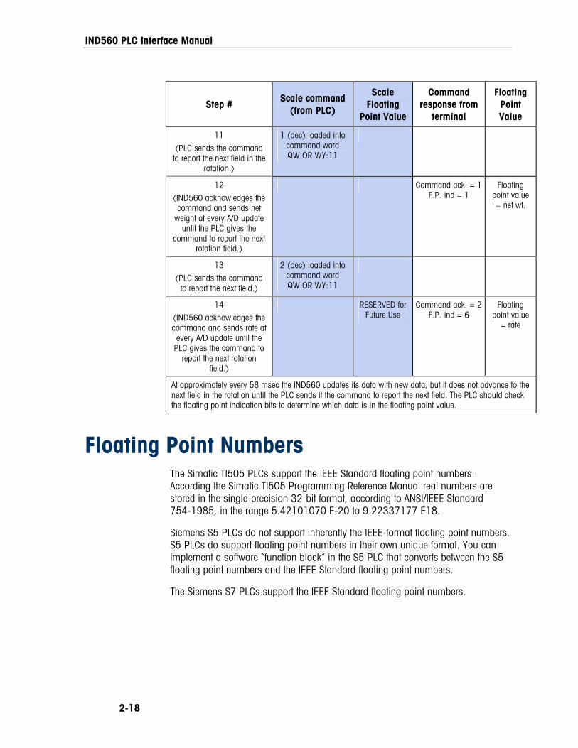
IND560 PLC Interface Manual
2-18
Step # Scale command
(from PLC)
Scale Floating
Point Value
Command response from
terminal
Floating Point Value
11
(PLC sends the command to report the next field in the
rotation.)
1 (dec) loaded into command word QW OR WY:11
12
(IND560 acknowledges the command and sends net
weight at every A/D update until the PLC gives the
command to report the next rotation field.)
Command ack. = 1F.P. ind = 1
Floating point value = net wt.
13
(PLC sends the command to report the next field.)
2 (dec) loaded into command word QW OR WY:11
14
(IND560 acknowledges the command and sends rate at every A/D update until the
PLC gives the command to report the next rotation
field.)
RESERVED for Future Use
Command ack. = 2F.P. ind = 6
Floating point value
= rate
At approximately every 58 msec the IND560 updates its data with new data, but it does not advance to the next field in the rotation until the PLC sends it the command to report the next field. The PLC should check the floating point indication bits to determine which data is in the floating point value.
Floating Point Numbers The Simatic TI505 PLCs support the IEEE Standard floating point numbers. According the Simatic TI505 Programming Reference Manual real numbers are stored in the single-precision 32-bit format, according to ANSI/IEEE Standard 754-1985, in the range 5.42101070 E-20 to 9.22337177 E18.
Siemens S5 PLCs do not support inherently the IEEE-format floating point numbers. S5 PLCs do support floating point numbers in their own unique format. You can implement a software “function block” in the S5 PLC that converts between the S5 floating point numbers and the IEEE Standard floating point numbers.
The Siemens S7 PLCs support the IEEE Standard floating point numbers.
IND560 PLC Interface Manual
2-19
Shared Data
Operational Overview PROFIBUS PLCs can access the terminal’s Shared Data. Since the PROFIBUS communications supports up to 244-byte messages at speeds typically in the range of 1.5 to 12 megahertz, there is not a need for two separate modes of communication unlike Allen-Bradley and its block transfer. PROFIBUS PLCs can read IND560 Shared Data variables, write new values to IND560 Shared Data variables, and write operator messages on the terminal’s lower display. For PROFIBUS, the PLC output data had additional fields for accessing Shared Data. The PLC must specify the Shared Data command and variable name in the PLC output message. If the command is a write command, then the PLC output message must also contain the write field value. The maximum length of the value is 20 bytes. When the Shared Data command is a read command, the PLC input message will have a read field containing the data from the Shared Data variable specified in the output message. The maximum length of the data reported in the read field is 20 bytes. The Shared Data variables are self-typing. The IND560 terminal determines the type of any valid data field in the message from the variable’s name and definition in Shared Data. The terminal will not allow string data to be written in a floating point variable or visa versa.
Shared Data Input The input information for the shared data consists of two sections: the shared data status and the shared data read field value (if requested by the shared data output command). The shared data status information is a word that contains an integer value. This integer value represents one of the following status values:
0 Null status
1 Command completed successfully
2 Invalid shared data name
3 Invalid shared data command
4 Cannot write because field is write-protected (legal for trade)
The shared data read field value contains the value of the shared data variable specified in the shared data output (from the PLC to the terminal). It is only present when the command from the shared data output requests read shared data. This value is self-typing; for example, it could be a floating point number or a string variable. The length is determined by the variable selected but will not exceed 20 bytes. See the tables following the Shared Data Output for a list of possible variables and their contents.
IND560 PLC Interface Manual
2-20
Shared Data Output The output information for the shared data consists of four sections: the shared data command, the shared data name, the shared data variable name, and the shared data write value (if required by the shared data output command). The shared data command information is a word that contains an integer value. This integer value represents one of the following status values:
0 Null command
1 Read shared data
2 Write shared data
The terminal processes a shared data command “on demand” by the PLC. When a new value is placed in the shared data command word, the terminal will perform the command issued. The terminal does not provide “real time” information to the PLC; it supplies a “snapshot’ of the data not an automatic update of new values of the same shared data command. Instead, the PLC must request the information again by setting a new value in the shared data command word.
To do successive reads, for example, the PLC must alternate between a “null” command and a “read” command in the shared data command word. For the most efficient processing, the PLC should set up the terminal name, the variable name, and the write value (if any) while it is setting the “null” command. Once that is completed, the PLC can then set the shared data command to “read” or “write”.
Refer to the Shared Data Reference List for a complete listing of Shared Data Fields.
Discrete Data I/O Space Usage Comparison The following tables show a comparison of the integer, division, floating point, and shared data formats’ input and output data usage.
Table 2-11 shows a comparison between the integer data formats and the floating point format of the input data. The input data is from the IND560 terminal to the PLC, with node configured beginning at address “0” and data format configured for four Message Slots.
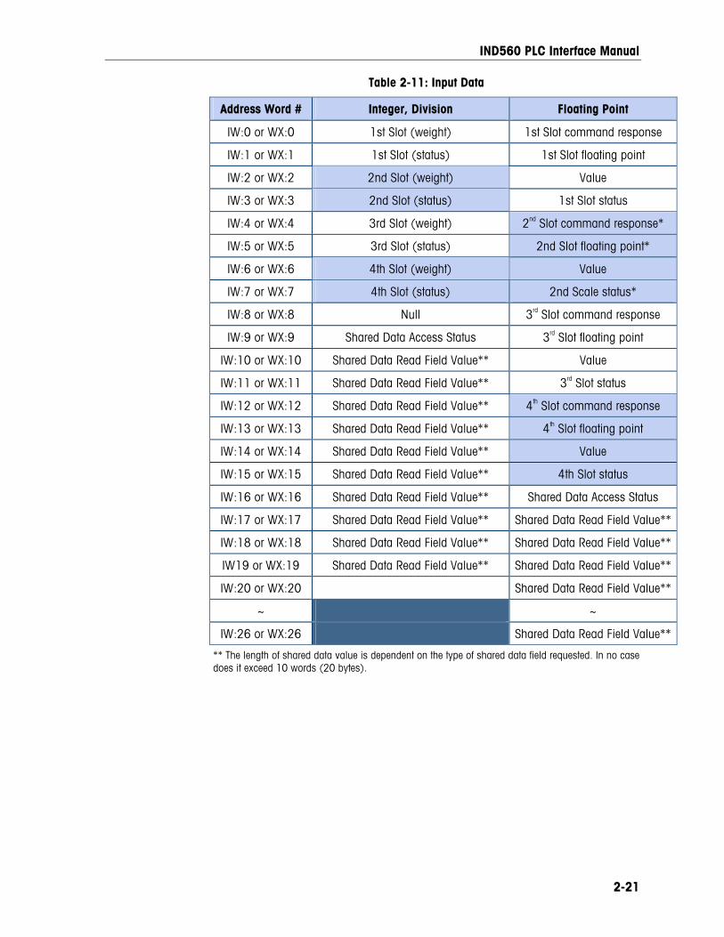
IND560 PLC Interface Manual
2-21
Table 2-11: Input Data
Address Word # Integer, Division Floating Point
IW:0 or WX:0 1st Slot (weight) 1st Slot command response
IW:1 or WX:1 1st Slot (status) 1st Slot floating point
IW:2 or WX:2 2nd Slot (weight) Value
IW:3 or WX:3 2nd Slot (status) 1st Slot status
IW:4 or WX:4 3rd Slot (weight) 2nd Slot command response*
IW:5 or WX:5 3rd Slot (status) 2nd Slot floating point*
IW:6 or WX:6 4th Slot (weight) Value
IW:7 or WX:7 4th Slot (status) 2nd Scale status*
IW:8 or WX:8 Null 3rd Slot command response
IW:9 or WX:9 Shared Data Access Status 3rd Slot floating point
IW:10 or WX:10 Shared Data Read Field Value** Value
IW:11 or WX:11 Shared Data Read Field Value** 3rd Slot status
IW:12 or WX:12 Shared Data Read Field Value** 4th Slot command response
IW:13 or WX:13 Shared Data Read Field Value** 4th Slot floating point
IW:14 or WX:14 Shared Data Read Field Value** Value
IW:15 or WX:15 Shared Data Read Field Value** 4th Slot status
IW:16 or WX:16 Shared Data Read Field Value** Shared Data Access Status
IW:17 or WX:17 Shared Data Read Field Value** Shared Data Read Field Value**
IW:18 or WX:18 Shared Data Read Field Value** Shared Data Read Field Value**
IW19 or WX:19 Shared Data Read Field Value** Shared Data Read Field Value**
IW:20 or WX:20 Shared Data Read Field Value**
~ ~
IW:26 or WX:26 Shared Data Read Field Value**
** The length of shared data value is dependent on the type of shared data field requested. In no case does it exceed 10 words (20 bytes).
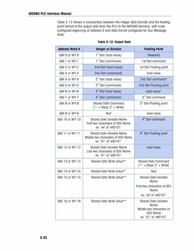
IND560 PLC Interface Manual
2-22
Table 2-12 shows a comparison between the integer data formats and the floating point format of the output data from the PLC to the IND560 terminal, with node configured beginning at address 0 and data format configured for four Message Slots.
Table 2-12: Output Data
Address Word # Integer or Division Floating Point
QW:0 or WY:0 1st Slot (load value) Reserved
QW:1 or WY:1 1st Slot (command) 1st Slot command
QW:2 or WY:2 2nd Slot (load value) 1st Slot Floating point
QW:3 or WY:3 2nd Slot (command) load value
QW:4 or WY:4 3rd Slot (load value) 2nd Slot command*
QW:5 or WY:5 3rd Slot (command) 2nd Slot Floating point
QW:6 or WY:6 4th Slot (load value) load value*
QW:7 or WY:7 4th Slot (command) 3rd Slot command
QW:8 or WY:8 Shared Data Command (‘1’ = Read,’2’ = Write)
3rd Slot Floating point
QW:9 or WY:9 Null load value
QW:10 or WY:10 Shared Data Variable Name First two characters of SDV Name
ex: ‘wt’ of ‘wt0101’
4th Slot command
QW:11 or WY:11 Shared Data Variable Name Middle two characters of SDV Name
ex: ‘01’ of ‘wt0101’
4th Slot Floating point
QW:12 or WY:12 Shared Data Variable Name Last two characters of SDV Name
ex: ‘01’ of ‘wt0101’
load value
QW:13 or WY:13 Shared Data Write Value** Shared Data Command (‘1’ = Read,’2’ = Write)
QW:14 or WY:14 Shared Data Write Value** Null
QW:15 or WY:15 Shared Data Write Value** Shared Data Variable Name
First two characters of SDV Name
ex: ‘wt’ of ‘wt0101’
QW:16 or WY:16 Shared Data Write Value** Shared Data Variable Name
Middle two characters of SDV Name
ex: ‘01’ of ‘wt0101’
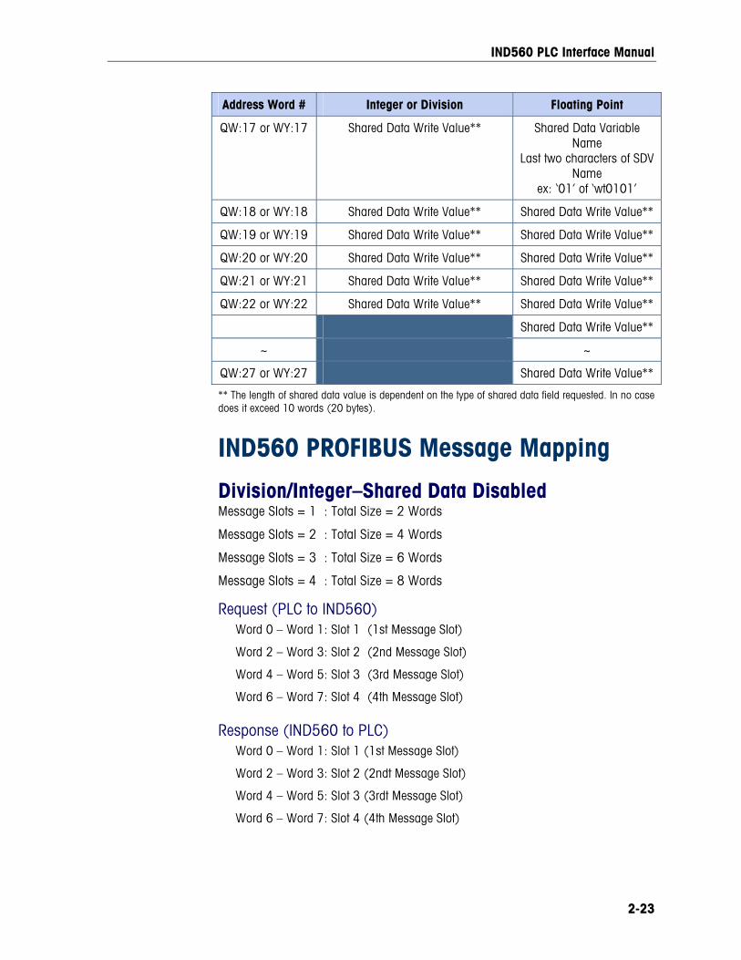
IND560 PLC Interface Manual
2-23
Address Word # Integer or Division Floating Point
QW:17 or WY:17 Shared Data Write Value** Shared Data Variable Name
Last two characters of SDV Name
ex: ‘01’ of ‘wt0101’
QW:18 or WY:18 Shared Data Write Value** Shared Data Write Value**
QW:19 or WY:19 Shared Data Write Value** Shared Data Write Value**
QW:20 or WY:20 Shared Data Write Value** Shared Data Write Value**
QW:21 or WY:21 Shared Data Write Value** Shared Data Write Value**
QW:22 or WY:22 Shared Data Write Value** Shared Data Write Value**
Shared Data Write Value**
~ ~
QW:27 or WY:27 Shared Data Write Value**
** The length of shared data value is dependent on the type of shared data field requested. In no case does it exceed 10 words (20 bytes).
IND560 PROFIBUS Message Mapping
Division/Integer–Shared Data Disabled Message Slots = 1 : Total Size = 2 Words
Message Slots = 2 : Total Size = 4 Words
Message Slots = 3 : Total Size = 6 Words
Message Slots = 4 : Total Size = 8 Words
Request (PLC to IND560) Word 0 – Word 1: Slot 1 (1st Message Slot)
Word 2 – Word 3: Slot 2 (2nd Message Slot)
Word 4 – Word 5: Slot 3 (3rd Message Slot)
Word 6 – Word 7: Slot 4 (4th Message Slot)
Response (IND560 to PLC) Word 0 – Word 1: Slot 1 (1st Message Slot)
Word 2 – Word 3: Slot 2 (2ndt Message Slot)
Word 4 – Word 5: Slot 3 (3rdt Message Slot)
Word 6 – Word 7: Slot 4 (4th Message Slot)
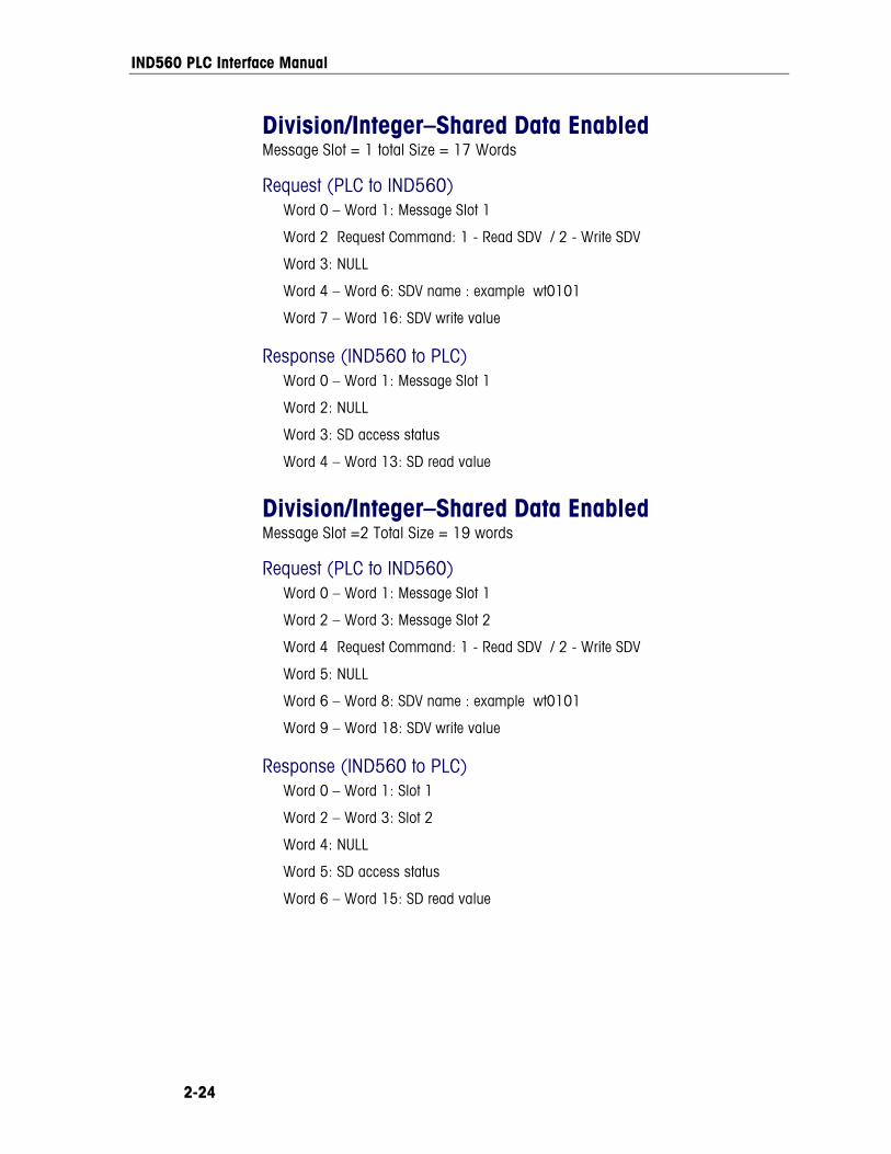
IND560 PLC Interface Manual
2-24
Division/Integer–Shared Data Enabled Message Slot = 1 total Size = 17 Words
Request (PLC to IND560) Word 0 – Word 1: Message Slot 1
Word 2 Request Command: 1 - Read SDV / 2 - Write SDV
Word 3: NULL
Word 4 – Word 6: SDV name : example wt0101
Word 7 – Word 16: SDV write value
Response (IND560 to PLC) Word 0 – Word 1: Message Slot 1
Word 2: NULL
Word 3: SD access status
Word 4 – Word 13: SD read value
Division/Integer–Shared Data Enabled Message Slot =2 Total Size = 19 words
Request (PLC to IND560) Word 0 – Word 1: Message Slot 1
Word 2 – Word 3: Message Slot 2
Word 4 Request Command: 1 - Read SDV / 2 - Write SDV
Word 5: NULL
Word 6 – Word 8: SDV name : example wt0101
Word 9 – Word 18: SDV write value
Response (IND560 to PLC) Word 0 – Word 1: Slot 1
Word 2 – Word 3: Slot 2
Word 4: NULL
Word 5: SD access status
Word 6 – Word 15: SD read value
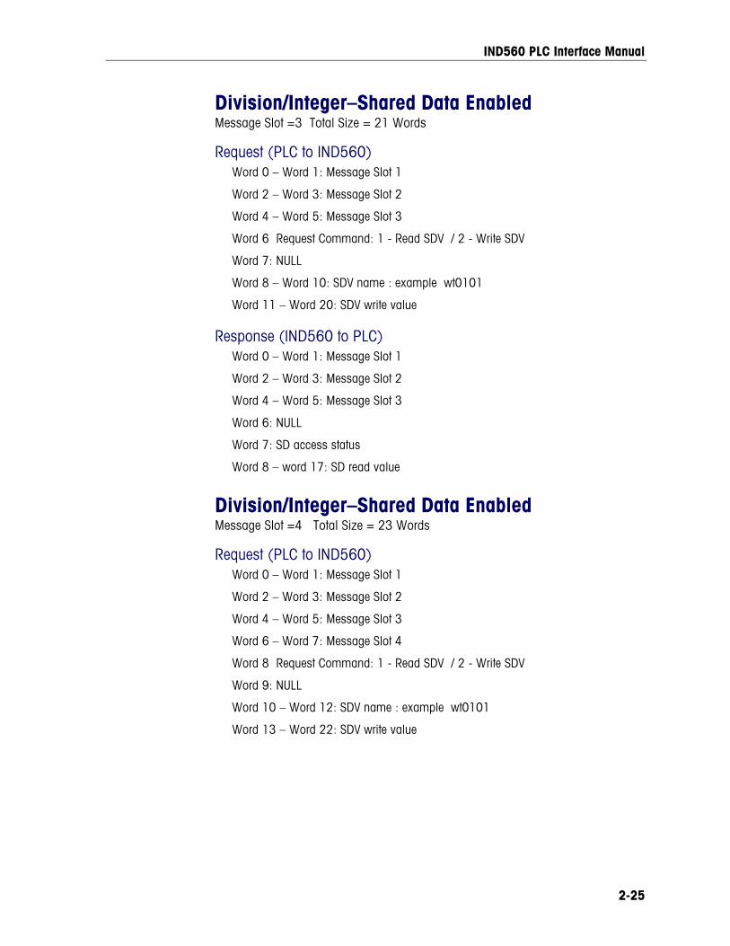
IND560 PLC Interface Manual
2-25
Division/Integer–Shared Data Enabled Message Slot =3 Total Size = 21 Words
Request (PLC to IND560) Word 0 – Word 1: Message Slot 1
Word 2 – Word 3: Message Slot 2
Word 4 – Word 5: Message Slot 3
Word 6 Request Command: 1 - Read SDV / 2 - Write SDV
Word 7: NULL
Word 8 – Word 10: SDV name : example wt0101
Word 11 – Word 20: SDV write value
Response (IND560 to PLC) Word 0 – Word 1: Message Slot 1
Word 2 – Word 3: Message Slot 2
Word 4 – Word 5: Message Slot 3
Word 6: NULL
Word 7: SD access status
Word 8 – word 17: SD read value
Division/Integer–Shared Data Enabled Message Slot =4 Total Size = 23 Words
Request (PLC to IND560) Word 0 – Word 1: Message Slot 1
Word 2 – Word 3: Message Slot 2
Word 4 – Word 5: Message Slot 3
Word 6 – Word 7: Message Slot 4
Word 8 Request Command: 1 - Read SDV / 2 - Write SDV
Word 9: NULL
Word 10 – Word 12: SDV name : example wt0101
Word 13 – Word 22: SDV write value
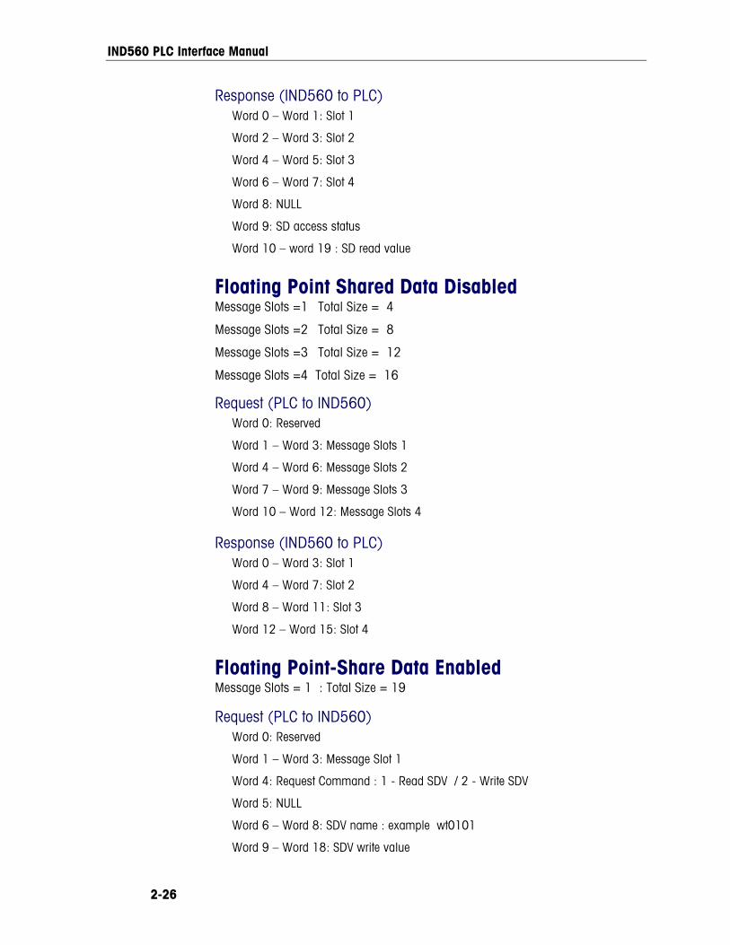
IND560 PLC Interface Manual
2-26
Response (IND560 to PLC) Word 0 – Word 1: Slot 1
Word 2 – Word 3: Slot 2
Word 4 – Word 5: Slot 3
Word 6 – Word 7: Slot 4
Word 8: NULL
Word 9: SD access status
Word 10 – word 19 : SD read value
Floating Point Shared Data Disabled Message Slots =1 Total Size = 4
Message Slots =2 Total Size = 8
Message Slots =3 Total Size = 12
Message Slots =4 Total Size = 16
Request (PLC to IND560) Word 0: Reserved
Word 1 – Word 3: Message Slots 1
Word 4 – Word 6: Message Slots 2
Word 7 – Word 9: Message Slots 3
Word 10 – Word 12: Message Slots 4
Response (IND560 to PLC) Word 0 – Word 3: Slot 1
Word 4 – Word 7: Slot 2
Word 8 – Word 11: Slot 3
Word 12 – Word 15: Slot 4
Floating Point-Share Data Enabled Message Slots = 1 : Total Size = 19
Request (PLC to IND560) Word 0: Reserved
Word 1 – Word 3: Message Slot 1
Word 4: Request Command : 1 - Read SDV / 2 - Write SDV
Word 5: NULL
Word 6 – Word 8: SDV name : example wt0101
Word 9 – Word 18: SDV write value
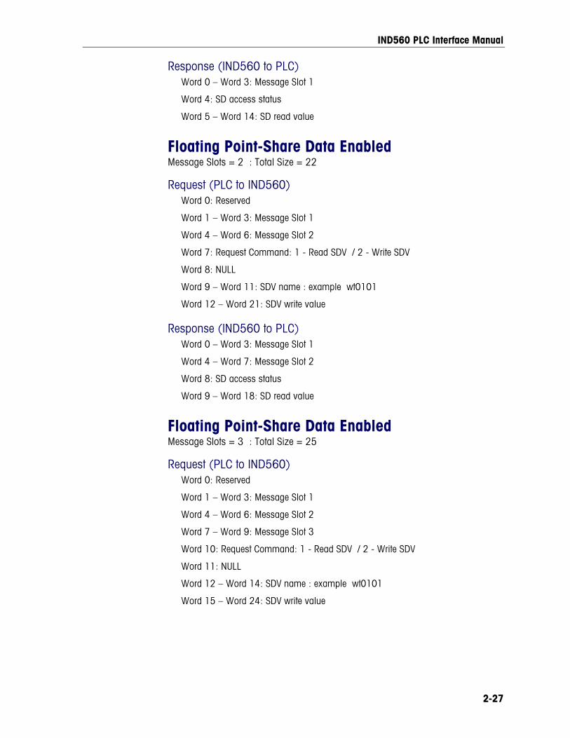
IND560 PLC Interface Manual
2-27
Response (IND560 to PLC) Word 0 – Word 3: Message Slot 1
Word 4: SD access status
Word 5 – Word 14: SD read value
Floating Point-Share Data Enabled Message Slots = 2 : Total Size = 22
Request (PLC to IND560) Word 0: Reserved
Word 1 – Word 3: Message Slot 1
Word 4 – Word 6: Message Slot 2
Word 7: Request Command: 1 - Read SDV / 2 - Write SDV
Word 8: NULL
Word 9 – Word 11: SDV name : example wt0101
Word 12 – Word 21: SDV write value
Response (IND560 to PLC) Word 0 – Word 3: Message Slot 1
Word 4 – Word 7: Message Slot 2
Word 8: SD access status
Word 9 – Word 18: SD read value
Floating Point-Share Data Enabled Message Slots = 3 : Total Size = 25
Request (PLC to IND560) Word 0: Reserved
Word 1 – Word 3: Message Slot 1
Word 4 – Word 6: Message Slot 2
Word 7 – Word 9: Message Slot 3
Word 10: Request Command: 1 - Read SDV / 2 - Write SDV
Word 11: NULL
Word 12 – Word 14: SDV name : example wt0101
Word 15 – Word 24: SDV write value
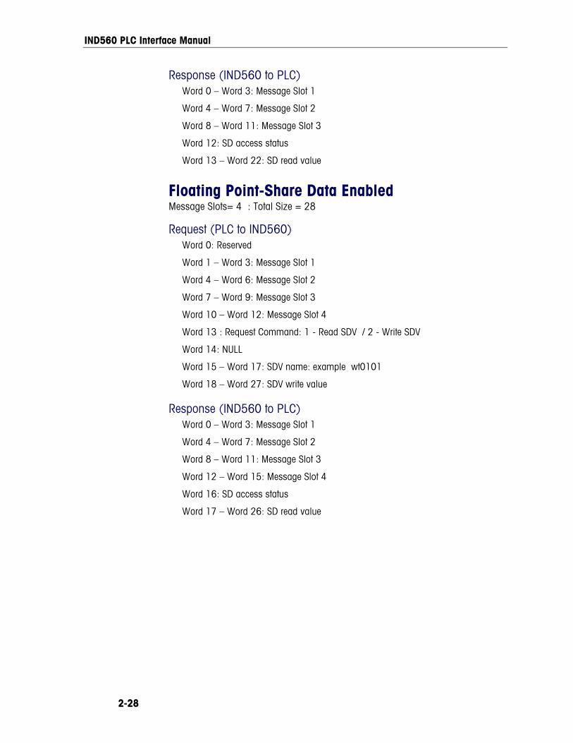
IND560 PLC Interface Manual
2-28
Response (IND560 to PLC) Word 0 – Word 3: Message Slot 1
Word 4 – Word 7: Message Slot 2
Word 8 – Word 11: Message Slot 3
Word 12: SD access status
Word 13 – Word 22: SD read value
Floating Point-Share Data Enabled Message Slots= 4 : Total Size = 28
Request (PLC to IND560) Word 0: Reserved
Word 1 – Word 3: Message Slot 1
Word 4 – Word 6: Message Slot 2
Word 7 – Word 9: Message Slot 3
Word 10 – Word 12: Message Slot 4
Word 13 : Request Command: 1 - Read SDV / 2 - Write SDV
Word 14: NULL
Word 15 – Word 17: SDV name: example wt0101
Word 18 – Word 27: SDV write value
Response (IND560 to PLC) Word 0 – Word 3: Message Slot 1
Word 4 – Word 7: Message Slot 2
Word 8 – Word 11: Message Slot 3
Word 12 – Word 15: Message Slot 4
Word 16: SD access status
Word 17 – Word 26: SD read value
IND560 PLC Interface Manual
2-29
Controlling Discrete I/O Using a PLC Interface The IND560 terminal provides the ability to directly control its discrete outputs and read its discrete inputs via the (digital) PLC interface options. System integrators should be aware that the IND560 discrete I/O updates are synchronized with the A/D rate, not with the PLC I/O scan rate. This may cause a noticeable delay in reading inputs or updating outputs as observed from the PLC to real world signals. Note that the outputs must be unassigned in the IND560 terminal setup in order to be controlled by the PLC.
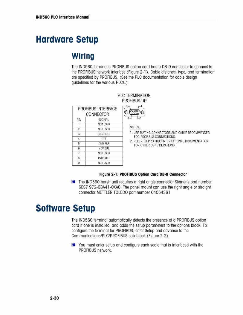
IND560 PLC Interface Manual
2-30
Hardware Setup
Wiring The IND560 terminal’s PROFIBUS option card has a DB-9 connector to connect to the PROFIBUS network interface (Figure 2-1). Cable distance, type, and termination are specified by PROFIBUS. (See the PLC documentation for cable design guidelines for the various PLCs.)
Figure 2-1: PROFIBUS Option Card DB-9 Connector
The IND560 harsh unit requires a right angle connector Siemens part number 6ES7 972-0BA41-0XA0. The panel mount can use the right angle or straight connector METTLER TOLEDO part number 64054361
Software Setup The IND560 terminal automatically detects the presence of a PROFIBUS option card if one is installed, and adds the setup parameters to the options block. To configure the terminal for PROFIBUS, enter Setup and advance to the Communications/PLC/PROFIBUS sub-block (Figure 2-2).
You must enter setup and configure each scale that is interfaced with the PROFIBUS network.
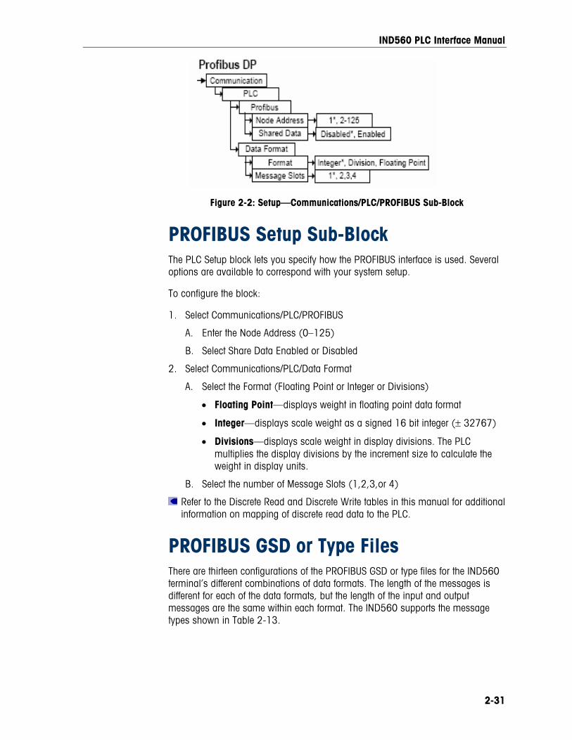
IND560 PLC Interface Manual
2-31
Figure 2-2: Setup—Communications/PLC/PROFIBUS Sub-Block
PROFIBUS Setup Sub-Block The PLC Setup block lets you specify how the PROFIBUS interface is used. Several options are available to correspond with your system setup.
To configure the block:
1. Select Communications/PLC/PROFIBUS
A. Enter the Node Address (0–125)
B. Select Share Data Enabled or Disabled
2. Select Communications/PLC/Data Format
A. Select the Format (Floating Point or Integer or Divisions)
• Floating Point—displays weight in floating point data format
• Integer—displays scale weight as a signed 16 bit integer (± 32767)
• Divisions—displays scale weight in display divisions. The PLC multiplies the display divisions by the increment size to calculate the weight in display units.
B. Select the number of Message Slots (1,2,3,or 4)
Refer to the Discrete Read and Discrete Write tables in this manual for additional information on mapping of discrete read data to the PLC.
PROFIBUS GSD or Type Files There are thirteen configurations of the PROFIBUS GSD or type files for the IND560 terminal’s different combinations of data formats. The length of the messages is different for each of the data formats, but the length of the input and output messages are the same within each format. The IND560 supports the message types shown in Table 2-13.
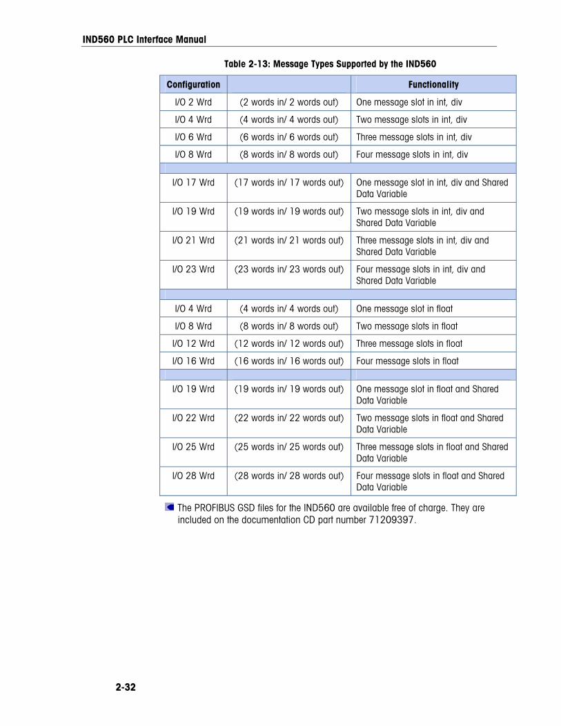
IND560 PLC Interface Manual
2-32
Table 2-13: Message Types Supported by the IND560
Configuration Functionality
I/O 2 Wrd (2 words in/ 2 words out) One message slot in int, div
I/O 4 Wrd (4 words in/ 4 words out) Two message slots in int, div
I/O 6 Wrd (6 words in/ 6 words out) Three message slots in int, div
I/O 8 Wrd (8 words in/ 8 words out) Four message slots in int, div
I/O 17 Wrd (17 words in/ 17 words out) One message slot in int, div and Shared Data Variable
I/O 19 Wrd (19 words in/ 19 words out) Two message slots in int, div and Shared Data Variable
I/O 21 Wrd (21 words in/ 21 words out) Three message slots in int, div and Shared Data Variable
I/O 23 Wrd (23 words in/ 23 words out) Four message slots in int, div and Shared Data Variable
I/O 4 Wrd (4 words in/ 4 words out) One message slot in float
I/O 8 Wrd (8 words in/ 8 words out) Two message slots in float
I/O 12 Wrd (12 words in/ 12 words out) Three message slots in float
I/O 16 Wrd (16 words in/ 16 words out) Four message slots in float
I/O 19 Wrd (19 words in/ 19 words out) One message slot in float and Shared Data Variable
I/O 22 Wrd (22 words in/ 22 words out) Two message slots in float and Shared Data Variable
I/O 25 Wrd (25 words in/ 25 words out) Three message slots in float and Shared Data Variable
I/O 28 Wrd (28 words in/ 28 words out) Four message slots in float and Shared Data Variable
The PROFIBUS GSD files for the IND560 are available free of charge. They are included on the documentation CD part number 71209397.
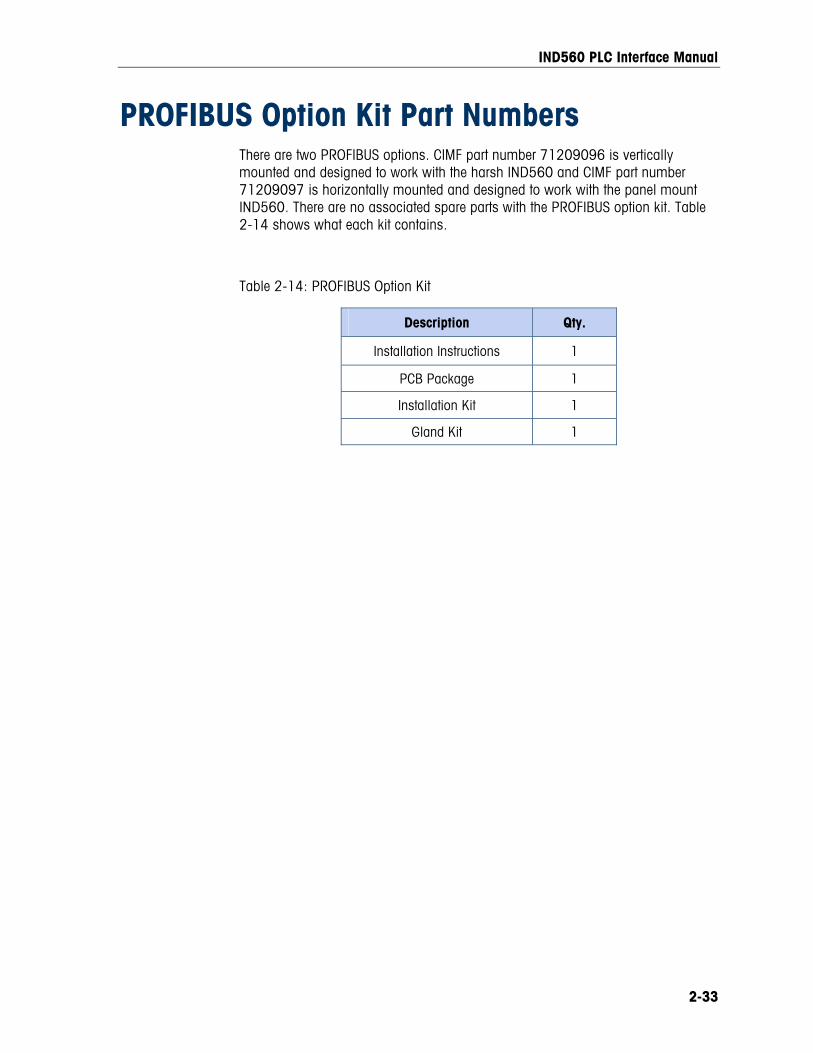
IND560 PLC Interface Manual
2-33
PROFIBUS Option Kit Part Numbers There are two PROFIBUS options. CIMF part number 71209096 is vertically mounted and designed to work with the harsh IND560 and CIMF part number 71209097 is horizontally mounted and designed to work with the panel mount IND560. There are no associated spare parts with the PROFIBUS option kit. Table 2-14 shows what each kit contains.
Table 2-14: PROFIBUS Option Kit
Description Qty.
Installation Instructions 1
PCB Package 1
Installation Kit 1
Gland Kit 1
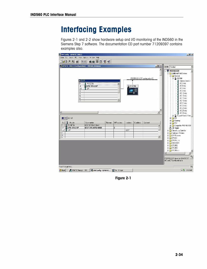
IND560 PLC Interface Manual
2-34
Interfacing Examples Figures 2-1 and 2-2 show hardware setup and I/O monitoring of the IND560 in the Siemens Step 7 software. The documentation CD part number 71209397 contains examples also.
Figure 2-1
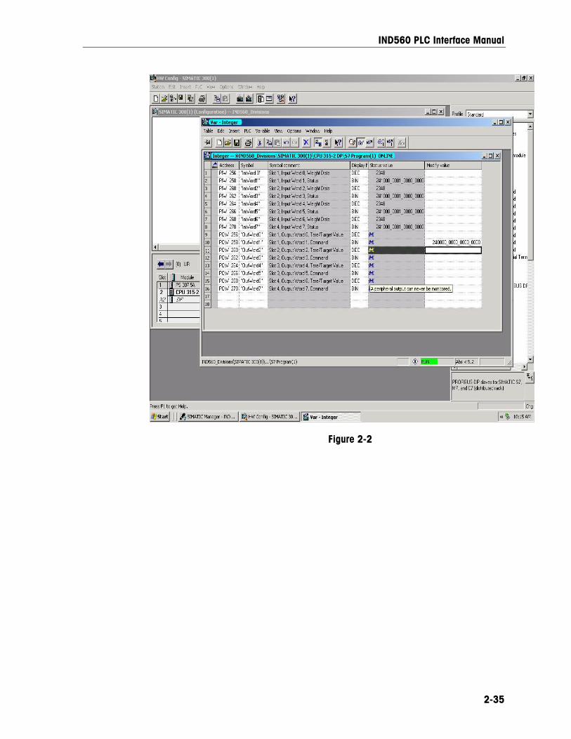
IND560 PLC Interface Manual
2-35
Figure 2-2

IND560 PLC Interface Manual
2-36
For your notes
3-1
Chapter 3.0 Analog Output Kit Option
The Analog Output option kit provides an isolated 4-20 mA or 0-10 VDC analog signal output for gross weight or displayed weight. The outputs will be low when the displayed weight is at zero. When the displayed weight reaches maximum capacity, the outputs will increase to the maximum (20 mA or 10 VDC). Any weight between zero and full capacity will be represented as a percentage of the output proportional to the percentage of full scale capacity.
The Analog Output sub-block lets you select the data source and calibrate analog zero and full-scale values. The IND560 terminal must be calibrated to the desired scale before making Analog Output adjustments. The Analog Output card has one channel.
Data sources may be weight, none (for future use).
Specifications
Maximum Cable Length: 0-10 VDC – 50 ft (15.2 m) 4-20mA – 1000 ft (300 m)
Min/Max Load Resistance: 0-10 VDC – 100k ohms minimum 4-20 mA – 500 ohms maximum
Outputs:
Resolution:
1 channel capable of supplying 4-20 mA or 0-10 VDC
16 bit resolution - 65536 levels across scale build
Note: If the load resistance ratings are exceeded, the analog output will not operate properly.
IND560 PLC Interface Manual
3-2
Installation
WARNING! DISCONNECT ALL POWER TO THIS UNIT BEFORE REMOVING THE FUSE OR SERVICING.
CAUTION OBSERVE PRECAUTIONS FOR HANDLING ELECTROSTATIC SENSITIVE DEVICES.
WARNING! DO NOT APPLY POWER TO THE IND560 TERMINAL UNTIL INSTALLATION OF COMPONENTS AND EXTERNAL WIRING HAVE BEEN COMPLETED.
To install the Analog Output Option Kit PCB in the IND560 terminal:
1. Disconnect AC power to the IND560 terminal.
2. Remove the IND560 terminal rear panel if installing in a general purpose or harsh environment unit. On the panel mount version only, remove the cover plate from an open slot on the rear of the IND560 terminal.
3. Insert the Analog Output option card in an open slot in the rear of the terminal. Seat the card by inserting it into the slot, then tighten the thumbscrews finger tight.
4. Connect the external wiring to the Analog Output card outputs.
5. Install the rear covers on the general purpose or harsh environment versions.
6. Power up the terminal. The IND560 terminal will recognize the new option card automatically.
Setup In the IND560 Terminal Figure 3-1 illustrates the setup procedures for configuring the Analog Output Kit option.
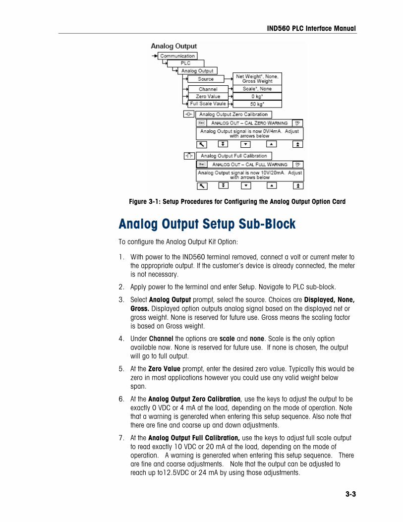
IND560 PLC Interface Manual
3-3
Figure 3-1: Setup Procedures for Configuring the Analog Output Option Card
Analog Output Setup Sub-Block To configure the Analog Output Kit Option:
1. With power to the IND560 terminal removed, connect a volt or current meter to the appropriate output. If the customer’s device is already connected, the meter is not necessary.
2. Apply power to the terminal and enter Setup. Navigate to PLC sub-block.
3. Select Analog Output prompt, select the source. Choices are Displayed, None, Gross. Displayed option outputs analog signal based on the displayed net or gross weight. None is reserved for future use. Gross means the scaling factor is based on Gross weight.
4. Under Channel the options are scale and none. Scale is the only option available now. None is reserved for future use. If none is chosen, the output will go to full output.
5. At the Zero Value prompt, enter the desired zero value. Typically this would be zero in most applications however you could use any valid weight below span.
6. At the Analog Output Zero Calibration, use the keys to adjust the output to be exactly 0 VDC or 4 mA at the load, depending on the mode of operation. Note that a warning is generated when entering this setup sequence. Also note that there are fine and coarse up and down adjustments.
7. At the Analog Output Full Calibration, use the keys to adjust full scale output to read exactly 10 VDC or 20 mA at the load, depending on the mode of operation. A warning is generated when entering this setup sequence. There are fine and coarse adjustments. Note that the output can be adjusted to reach up to12.5VDC or 24 mA by using those adjustments.
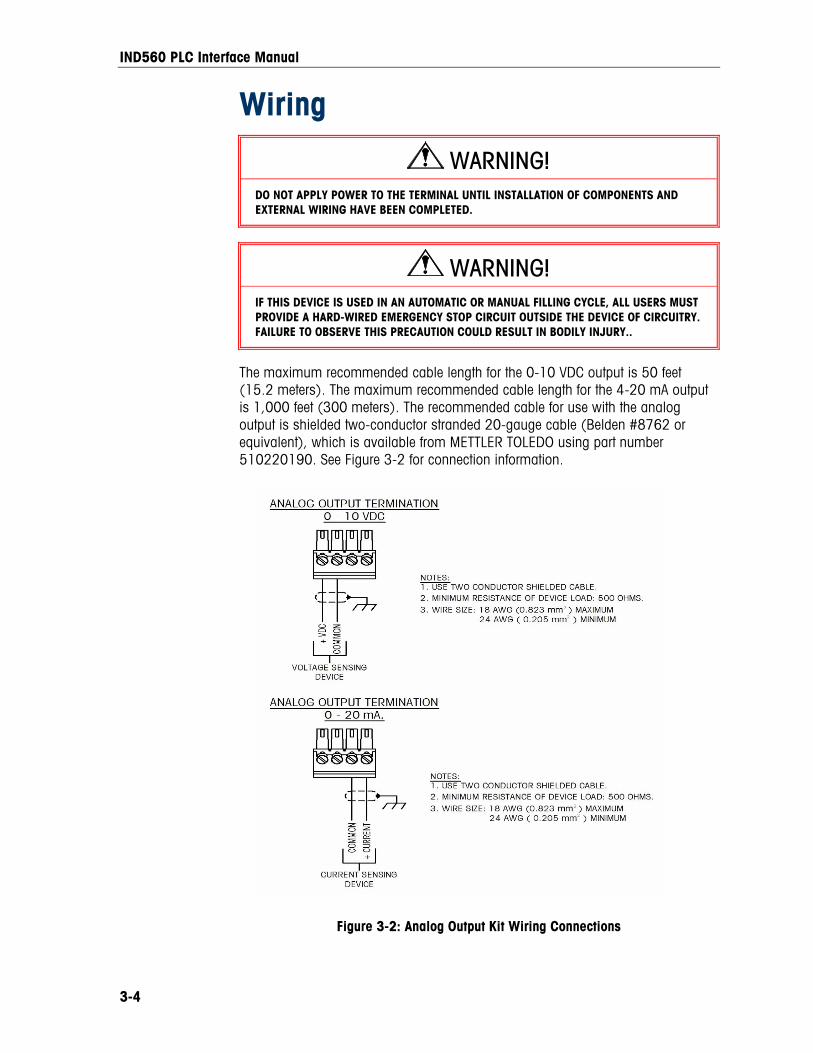
IND560 PLC Interface Manual
3-4
Wiring
WARNING! DO NOT APPLY POWER TO THE TERMINAL UNTIL INSTALLATION OF COMPONENTS AND EXTERNAL WIRING HAVE BEEN COMPLETED.
WARNING! IF THIS DEVICE IS USED IN AN AUTOMATIC OR MANUAL FILLING CYCLE, ALL USERS MUST PROVIDE A HARD-WIRED EMERGENCY STOP CIRCUIT OUTSIDE THE DEVICE OF CIRCUITRY. FAILURE TO OBSERVE THIS PRECAUTION COULD RESULT IN BODILY INJURY..
The maximum recommended cable length for the 0-10 VDC output is 50 feet (15.2 meters). The maximum recommended cable length for the 4-20 mA output is 1,000 feet (300 meters). The recommended cable for use with the analog output is shielded two-conductor stranded 20-gauge cable (Belden #8762 or equivalent), which is available from METTLER TOLEDO using part number 510220190. See Figure 3-2 for connection information.
Figure 3-2: Analog Output Kit Wiring Connections
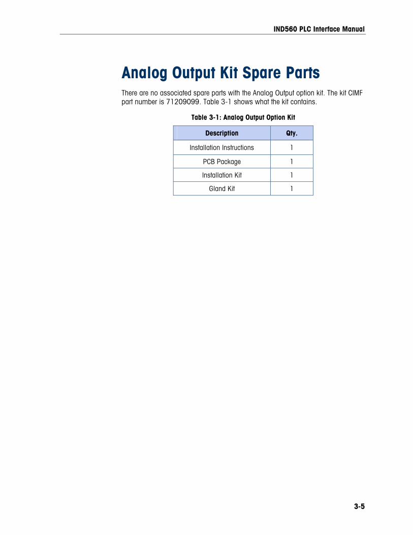
IND560 PLC Interface Manual
3-5
Analog Output Kit Spare Parts There are no associated spare parts with the Analog Output option kit. The kit CIMF part number is 71209099. Table 3-1 shows what the kit contains.
Table 3-1: Analog Output Option Kit
Description Qty.
Installation Instructions 1
PCB Package 1
Installation Kit 1
Gland Kit 1
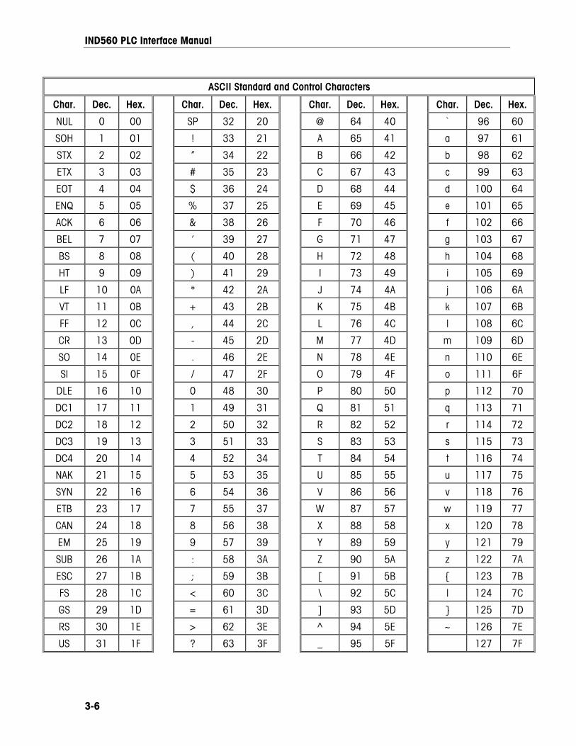
IND560 PLC Interface Manual
3-6
ASCII Standard and Control Characters
Char. Dec. Hex. Char. Dec. Hex. Char. Dec. Hex. Char. Dec. Hex.
NUL 0 00 SP 32 20 @ 64 40 ` 96 60
SOH 1 01 ! 33 21 A 65 41 a 97 61
STX 2 02 ” 34 22 B 66 42 b 98 62
ETX 3 03 # 35 23 C 67 43 c 99 63
EOT 4 04 $ 36 24 D 68 44 d 100 64
ENQ 5 05 % 37 25 E 69 45 e 101 65
ACK 6 06 & 38 26 F 70 46 f 102 66
BEL 7 07 ’ 39 27 G 71 47 g 103 67
BS 8 08 ( 40 28 H 72 48 h 104 68
HT 9 09 ) 41 29 I 73 49 i 105 69
LF 10 0A * 42 2A J 74 4A j 106 6A
VT 11 0B + 43 2B K 75 4B k 107 6B
FF 12 0C , 44 2C L 76 4C l 108 6C
CR 13 0D - 45 2D M 77 4D m 109 6D
SO 14 0E . 46 2E N 78 4E n 110 6E
SI 15 0F / 47 2F O 79 4F o 111 6F
DLE 16 10 0 48 30 P 80 50 p 112 70
DC1 17 11 1 49 31 Q 81 51 q 113 71
DC2 18 12 2 50 32 R 82 52 r 114 72
DC3 19 13 3 51 33 S 83 53 s 115 73
DC4 20 14 4 52 34 T 84 54 t 116 74
NAK 21 15 5 53 35 U 85 55 u 117 75
SYN 22 16 6 54 36 V 86 56 v 118 76
ETB 23 17 7 55 37 W 87 57 w 119 77
CAN 24 18 8 56 38 X 88 58 x 120 78
EM 25 19 9 57 39 Y 89 59 y 121 79
SUB 26 1A : 58 3A Z 90 5A z 122 7A
ESC 27 1B ; 59 3B [ 91 5B { 123 7B
FS 28 1C < 60 3C \ 92 5C | 124 7C
GS 29 1D = 61 3D ] 93 5D } 125 7D
RS 30 1E > 62 3E ^ 94 5E ~ 126 7E
US 31 1F ? 63 3F _ 95 5F 127 7F
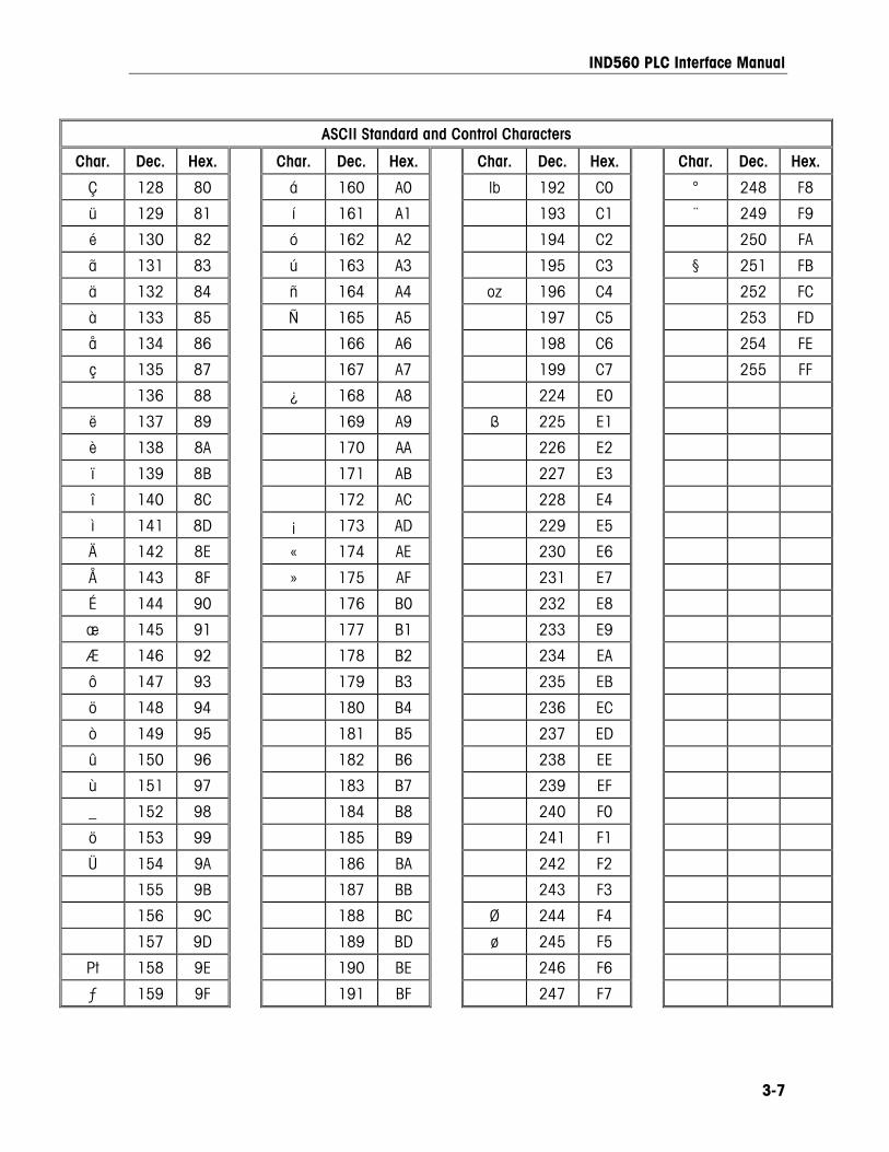
IND560 PLC Interface Manual
3-7
ASCII Standard and Control Characters
Char. Dec. Hex. Char. Dec. Hex. Char. Dec. Hex. Char. Dec. Hex.
Ç 128 80 á 160 A0 lb 192 C0 ° 248 F8
ü 129 81 í 161 A1 193 C1 ¨ 249 F9
é 130 82 ó 162 A2 194 C2 250 FA
ã 131 83 ú 163 A3 195 C3 § 251 FB
ä 132 84 ñ 164 A4 oz 196 C4 252 FC
à 133 85 Ñ 165 A5 197 C5 253 FD
å 134 86 166 A6 198 C6 254 FE
ç 135 87 167 A7 199 C7 255 FF
136 88 ¿ 168 A8 224 E0
ë 137 89 169 A9 ß 225 E1
è 138 8A 170 AA 226 E2
ï 139 8B 171 AB 227 E3
î 140 8C 172 AC 228 E4
ì 141 8D ¡ 173 AD 229 E5
Ä 142 8E « 174 AE 230 E6
Å 143 8F » 175 AF 231 E7
É 144 90 176 B0 232 E8
æ 145 91 177 B1 233 E9
Æ 146 92 178 B2 234 EA
ô 147 93 179 B3 235 EB
ö 148 94 180 B4 236 EC
ò 149 95 181 B5 237 ED
û 150 96 182 B6 238 EE
ù 151 97 183 B7 239 EF
_ 152 98 184 B8 240 F0
ö 153 99 185 B9 � 241 F1
Ü 154 9A 186 BA 242 F2
155 9B 187 BB 243 F3
156 9C 188 BC Ø 244 F4
157 9D 189 BD ø 245 F5
Pt 158 9E 190 BE � 246 F6
ƒ 159 9F 191 BF 247 F7

IND560 PLC Interface Manual
3-8
For your notes

1900 Polaris Parkway Columbus, Ohio 43240
METTLER TOLEDO® is a registered trademark of Mettler-Toledo, Inc.
©2005 Mettler-Toledo, Inc.