Embed Size (px)
Citation preview
Needle localization for needle steering under 3D ultrasound feedback*
Guillaume Lapouge1,2, Jocelyne Troccaz1, Philippe Poignet2
Abstract— In needle steering, estimating the needle pose isa critical problem. In 3D ultrasound volumes, fine needlelocalization is difficult and requires a combination of estimationand image processing to be successful. Indeed, 3D ultrasoundimaging suffers from noise, artifacts and works at a lowfrequency. We propose a needle tip pose estimation method inthe context of 3D robotic needle steering under 3D ultrasoundfeedback, based on multi-rate, multi-sensor fusion [1].
I. INTRODUCTION
In surgery, the success of percutaneous operations seemsclosely related to the precision of the procedure. To increasethe procedure efficacy, robotic needle steering has beenextensively researched. Needle steering requires feedbackfor closed loop control of a flexible needle. This feedbackconsists, most of the time, in ultrasound (US) imaging forits ease of use despite the quality of the acquired images.
3D robotic needle steering has been validated with camera-based feedback in [2]. In the context of clinically-compatibleUS feedback, most solutions (i.e. [4], [5] and [6]) involvethe translation of a 2D probe used in B-mode imaging tofollow the needle tip during the insertion. This feedback isreferred to as 2.5D US imaging. It aims at solving the poorneedle detection in the ultrasound images by putting a 2D,25 Hz US probe in position of needle maximal visibility(i.e. orthogonal to the needle shaft). Such a feedback makesthe needle localization easier but may prove difficult totranspose to a clinical use. Indeed, the translation of theprobe requires an external device and might cause unwantedtissue deformation.
3D US probes seem more adapted to a clinical use thantheir 2D counterparts. However, their low framerate (around1 Hz) and low image quality represent a challenge for preciseneedle localization.
A. 3D US probe used in Doppler mode
3D US imaging set in Doppler mode has been used in [7].In this study, the needle is vibrated with an external device.The vibrations are then detected by the probe and the needleis defined as the curve that best fits the doppler patches inthe volume. The clinical application of such a method seemshowever difficult for security and practical reasons.
A method without need for vibrations has been devel-oped in [8]. In this study, the needle is rotated duringthe acquisition, this rotation is then detected in Doppler
*This work was partly supported by the Investissements d’Avenir pro-gramme (Labex CAMI) under reference ANR-11-LABX-0004
1Univ. Grenoble Alpes, CNRS, Grenoble INP, TIMC-IMAG, F-38000Grenoble, France
2Univ. Montpellier, CNRS, LIRMM, F-34090 Montpellier, [email protected]
mode. However, the precision of this method is low despiteadditional constraints put on the needle insertion.
Doppler mode for needle steering seems adequate whenthe needle is not visible in B-mode images. However, itrequires additional constraints which may prove difficult totranspose to a clinical application.
B. 3D US probe used in B-mode
Needle steering under 3D US B-mode imaging has veryrarely be developed. The reason lies in the difficulty to detectfine needles in volumes that are noisy, acquired at 1 Hz andsuffer from many artifacts. Besides, analysing the entire 3DUS volume would be computationally too costly.
In [9] the needle is kept in a position of best visibility byguiding the ultrasound probe with a robot. The needle posi-tion is estimated by a Kalman filter which will also providea region of interest (ROI) for the next segmentation. Insidethis ROI, and after an intensity-based voxel binarisation, aRANSAC algorithm fits a Bezier curve to the resulting 3Ddata. This method was augmented with particle filtering in[10]. However, the needle is manually inserted in this studyand no information about insertion speed and rotation istaken into account. In [11], we described a Kalman filterbased on a mechanical model and fed by the robot inputs.This filter provides a ROI for the needle localization. Theneedle is then detected similarly to the method mentionedbefore. A laser microetching of the needle roughens its sur-face for more echogenicity. However, the needle maximumcurvature is considered constant throughout the insertionwhich may not be the case in clinical applications.
II. CONTRIBUTION
A. Methods
To increase the quality of the needle tip pose estimation,we propose to take into account asynchronous multi-sensormeasurements. To do so, a multi-rate unscented Kalmanfiltering (as presented in [12]) is proposed. This filter willtake into account measurements coming from 3D B-modeUS imaging, from the robot sensors and from shear waveelasticity imaging (SWE) (cf. Figure 1).
The needle tip-tissue interaction is modelled by the bicyclemodel first introduced in [13] and under the form
˙
xyzαβγκ
=
cosα cosβ 0sinβ 0
cosβ sinα 0
κ cos γ secβ + κβcut
2 sin γ cos γ tanβ −βcut
2 sin γ
κ sin γ − κβcut
2 cos γ cos γ tanβ βcut
2 cos γ−κ cos γtanβ 1
0 0
[u1u2
](1)
where x, y and z are the Cartesian coordinates of theneedle tip in the 3D US volume frame [mm]; α, β and γare the yaw, pitch and roll of the needle tip [rad]; κ is thecurvature of the needle tip trajectory [mm−1]. The inputs u1and u2 correspond to the insertion speed [mm.s−1] and therotation speed [rad.s−1] of the needle tip respectively. βcutis the cutting angle detailed in [15].
SWE provides a measurement of tissues stiffness undersmall deformations. The stiffer the medium is, the smallerthe radius of curvature of the needle path is [4]. Therefore,SWE measurements can be considered as curvature measure-ments. Each needle was inserted into phantoms of differentstiffnesses to establish relationship between needle curvatureand tissue elasticity. A power curve is then fitted to the dataresulting in the following equation: κ = aEb, with κ theneedle curvature, E the tissue Young’s modulus and a, b ∈R2.
Because κ cos γtanβ is most of the time small, γ̇ ≈ u2and the needle base rotation measured by the robot canbe considered as a measurement of the tip roll angle γ.Needle tip segmentation in 3D B-mode US volumes providesa measurement of the Cartesian coordinates of the tip in theUS volume frame.
Fig. 1. Proposed structure of the multi-rate unscented Kalman filter. Dataflows are represented by arrows. Refresh rates are indicated in red whenspecifiable.
The measurement equation is, when all measurements areavailable, written as h(x) =
[x y z γ κ
]. Its size
varies with the number of measurements available. The filterruns at 100 Hz to take into account the robot measurements.
To take into account the poor imaging quality of the 3DUS probe, we propose to reset the covariance matrix of themeasurement noise R . Thus, the further the needle is fromthe US transducer, the poorer its visibility is and the higherthe corresponding term is reset in R.
When crossing the interface between two tissues of differ-ent elasticities, we expect the curvature of the needle path tochange. The term corresponding to κ in the error covariancematrix P is therefore reset. This reflects a decreased trust inthe current estimation.
B. Results
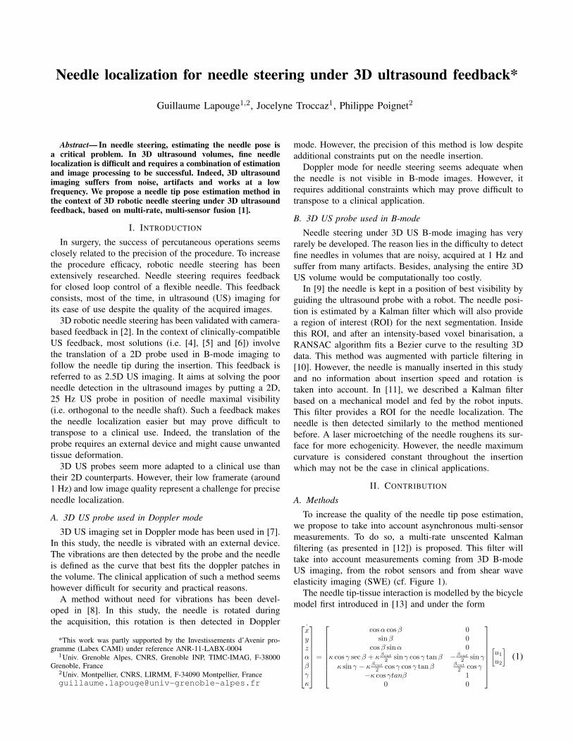
The system is composed of a robot holding the needleto insert it into a phantom (cf. Figure 2). The robot usedfor 24 Gauge Nitinol needle insertions has been developedfor prostate brachytherapy [14]. The ultrasound volumes areacquired every second with a 3D end-fire probe 4DEC-9/10
used with the Ultrasonix Sonix RP ultrasound system. TheUS volume voxels are 0.4 mm3 cubes. Pre-operative SWEmeasurements are taken into account.
Fig. 2. Experimental setup composed of the Prosper Robot (1), 3D USimaging system (2), Beveled-tip needle (3) and Pork tissue incorporated inAgar (4) [1].
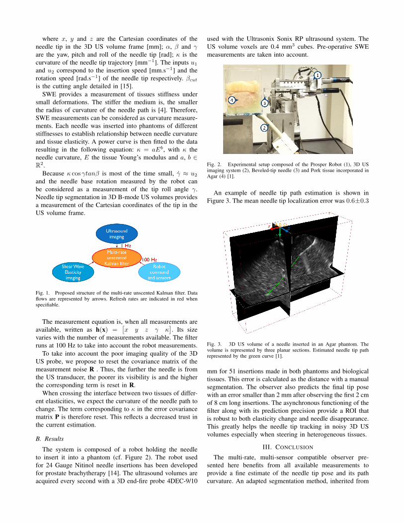
An example of needle tip path estimation is shown inFigure 3. The mean needle tip localization error was 0.6±0.3
Fig. 3. 3D US volume of a needle inserted in an Agar phantom. Thevolume is represented by three planar sections. Estimated needle tip pathrepresented by the green curve [1].
mm for 51 insertions made in both phantoms and biologicaltissues. This error is calculated as the distance with a manualsegmentation. The observer also predicts the final tip posewith an error smaller than 2 mm after observing the first 2 cmof 8 cm long insertions. The asynchronous functioning of thefilter along with its prediction precision provide a ROI thatis robust to both elasticity change and needle disappearance.This greatly helps the needle tip tracking in noisy 3D USvolumes especially when steering in heterogeneous tissues.
III. CONCLUSION
The multi-rate, multi-sensor compatible observer pre-sented here benefits from all available measurements toprovide a fine estimate of the needle tip pose and its pathcurvature. An adapted segmentation method, inherited from
[16], uses the resulting ROI for fine analysis of the 3DUS volumes and for needle tip segmentation. The proposedfiltering can also improve targeting. The good estimation ofthe tip behavior and its uncertainties could benefit adaptedcontrol laws and path planning methods.
REFERENCES
[1] G. Lapouge, J. Troccaz and P. Poignet, Multi-rate unscented Kalmanfiltering for pose and curvature estimation in 3D ultrasound-guidedneedle steering, Control Engineering Practice, Control EngineeringPractice, vol. 80, pp. 116-124, 2018.
[2] J. Chevrie, A. Krupa, and M. Babel, Online prediction of needle shapedeformation in moving soft tissues from visual feedback, InternationalConference on Intelligent Robots and Systems (IROS), IEEE/RSJ, pp.2375-2380, 2016.
[3] J. Huang, J. K. Triedman, N. V. Vasilyev, Y. Suematsu, R. O. Cleve-land, and P. E. Dupont, Imaging Artifacts of Medical Instruments inUltrasound-Guided Interventions, Journal of Ultrasound in Medicine,vol. 26, no. 10, pp. 1303-1322, 2007.
[4] P. Moreira and S. Misra, Biomechanics-based curvature estimation forultrasound-guided flexible needle steering in biological tissues, Annalsof biomedical engineering, vol. 43, no. 8, pp. 1716-1726, 2015.
[5] M. Abayazid, P. Moreira, N. Shahriari, S. Patil, R. Alterovitz, andS. Misra, Ultrasound-guided three-dimensional needle steering inbiological tissue with curved surfaces, Medical Engineering & Physics,vol. 37, no. 1, pp. 145-150, 2015.
[6] B. Fallahi, C. Rossa, R. S. Sloboda, N. Usmani, and M. Tavakoli,Sliding-based image-guided 3D needle steering in soft tissue, ControlEngineering Practice, vol. 63, pp. 34-43, Jun. 2017.
[7] T. K. Adebar and A. M. Okamura, 3D segmentation of curved needlesusing doppler ultrasound and vibration, in International Conference onInformation Processing in Computer-Assisted Interventions, 2013, p.61-70.
[8] P. Mignon, P. Poignet, and J. Troccaz, Using rotation for steerableneedle detection in 3D color-Doppler ultrasound images, InternationalConference on Engineering in Medicine and Biology Society (EMBC),IEEE, 2015, pp. 1544-1547.
[9] P. Chatelain, A. Krupa, and M. Marchal, Real-time needle detectionand tracking using a visually servoed 3D ultrasound probe, Interna-tional Conference on Robotics and Automation (ICRA), IEEE, 2013,p. 1676-1681.
[10] P. Chatelain, A. Krupa, and N. Navab, 3D ultrasound-guided roboticsteering of a flexible needle via visual servoing , International Confer-ence on Robotics and Automation (ICRA),IEEE, 2015, p. 2250-2255.
[11] P. Mignon, P. Poignet, and J. Troccaz, Automatic Robotic Steeringof Flexible Needles from 3D Ultrasound Images in Phantoms and ExVivo Biological Tissue, Annals of Biomedical Engineering, vol. 46,no. 9, pp. 1385-1396, 2018.
[12] L. Armesto, S. Chroust, M. Vincze, and J. Tornero, Multi-rate fusionwith vision and inertial sensors, International Conference on Roboticsand Automation (ICRA), IEEE , 2004, vol. 1, p. 193-199.
[13] R. J. Webster, J. S. Kim, N. J. Cowan, G. S. Chirikjian, and A. M. Oka-mura, Nonholonomic Modeling of Needle Steering, The InternationalJournal of Robotics Research, vol. 25, no. 5-6, p. 509-525, 2006.
[14] N. Hungr, M. Baumann, J.-A. Long, and J. Troccaz, A 3-D ultrasoundrobotic prostate brachytherapy system with prostate motion tracking,IEEE Transactions on Robotics, vol. 28, no. 6, pp. 1382-1397, 2012.
[15] M. Abayazid, R. J. Roesthuis, R. Reilink, and S. Misra, IntegratingDeflection Models and Image Feedback for Real-Time Flexible NeedleSteering, IEEE Transactions on Robotics, vol. 29, no. 2, pp. 542-553,2013.
[16] H. Younes, S. Voros, and J. Troccaz, Automatic needle localization in3D ultrasound images for brachytherapy, International Symposium onBiomedical Imaging (ISBI), IEEE, pp.1203-1207, 2018.