Embed Size (px)
Citation preview
Reversible unit, air source for outdoor installation
NECS_N_0202T_0612T_201211_EN
r HFCR-410A
(The photo of the unit is indicative and may change depending on the model)
Climaveneta Technical Bulletin
0202T - 0612T53 - 159 kW
NECS-N
Maximum reliabilityEase of maintenance Efficiency Integrated hydronic unit
II NECS-N_0202T_0612T
NECS-N
HFC R410A
SUMMARYNECS-N
0202T - 0612T
Liability disclaimerThis bulletin is not exhaustive about: installation, use, safety precautions, handling and transport. Refer to “General Manual for Installation” for further informations.This bulletin refers to standard executions, in particular for di-mension, weight, electric, hydraulic, aeraulic and refrigerant connections (whereas applicable). Contact Climaveneta Com-mercial Office for further drawings and schemes.
Climaveneta declines any liability derived from the bulletin’s use. This bulletin is of exclusive property of Climaveneta, and all forms of copy are prohibited. The information contained in this document may be modified without prior notice.
1. Product presentation 1.1 Maximum reliability 1.2 Ease of maintenance 1.3 Efficiency 1.4 Hydronic unit 1.5 Demand limit 1.6 Low-Noise versions
2. Unit description 2.1 Standard unit composition 2.2 Tests 2.3 Reference standards 2.4 Available versions 2.5 Accessories
3. Electronic controller4. Technical data
4.1 General technical data 4.2 Cooling capacity performance 4.3 Heat pump capacity performance
5. Selection limits 5.1 Ethylene glycol mixture 5.2 Fouling factors
6. Hydraulic data 6.1 Water flow and pressure drop
7. Hydronic groups (Optional)8. Electrical data9. Full load sound level10. Dimensional drawings11. Legend of pipe connections
pg. n° IIIpg. n° IIIpg. n° III pg. n° III pg. n° IIIpg. n° IIIpg. n° IIIpg. n° 1 pg. n° 1pg. n° 1pg. n° 1 pg. n° 2 pg. n° 2pg. n° 3pg. n° 5pg. n° 5pg. n° 9pg. n° 13pg. n° 21pg. n° 20pg. n° 20pg. n° 21pg. n° 21pg. n° 22pg. n° 25pg. n° 27pg. n° A1pg. n° A3
Company quality system certified to UNI EN ISO 9001
This company par-ticipates in the EuroventCertification Programme.The products are listed in theDirectory of certified products.
Eurovent certification applied to units with cool-
ing capacity up to 1500 kW for air cooled water chillers
and water cooled liquid chillers
III NECS-N_0202T_0612T
NECS-N
HFC R410A
This section contains general information on the NECS-N range of products. For detailed information refer to the specific sec-tions in this bulletin.
NECS-N unitsNECS-N 0202T-0612T is a range of air-condensed reversible units with R410A rotary Scroll compressors working on two separate and independent circuits and a shell and tube heat exchanger.This new NECS-N series has been designed to meet specific application requirements where continuity of operation needs to be ensured.
1.1 maximum reliabilityUnit with dual-circuit refrigerant section designed to ensure maximum efficiency at full load, ensuring continuity without in-terruption of operation in the event of temporary stop of one of the 2 circuits.
1.2 Ease of maintenanceShell and tube heat exchanger with low pressure drops, for use with very hard water. This the best solution for industrial proc-ess control applications.
1.3 EfficiencyStepless fan speed condensation control achieved via a phase-cutting device. This optimizes power consumption by adapting condensation to any environmental condition, whilst assuring minimum noise from the ventilation unit.
1.4 Hydronic unitThe integrated hydronic unit includes the main hydraulic com-ponents, including a low- or high-head pump. Shutoff valves upstream and downstream from each pump to facilitate re-placement operations without having to drain the hydraulicsystem. Automatic pump rotation system in the event of a breakdown without interrupting operation (only for units with a dual pump).
1.5 Demand LimitDigital input for enabling the restriction of maximum power of the unit output to a preset value. The function can be used as a load protection or energy saver system.
1.6 Low-Noise versionsThe silenced version (LN) is available for all sizes. Here, low noise levels are achieved by reducing the speed of rotation of the fans and increasing the insulation of the compressor cham-ber.
1. PRODUCT PRESENTATION

1 NECS-N_0202T_0612T
NECS-N
HFC R410A
Outdoor reversible heat pump for the production of chilled/hot water with hermetic rotary Scroll compressors, axial-flow fans, shell and tubes heat exchanger and thermostatic expansion valve. External panels in Peraluman and structure in aluminium sections. The range is equipped with two compressors on two independent refrigerant circuits.
2.1 Standard unit composition
Structure Specific structure for outdoor installation, made with a hot-gal-vanised sheet steel base of adequate thickness, painted with polyester powders. Specific panelling for outdoor installation in aluminium alloy which ensures total resistance to atmospheric agents, easily removable, made in such a way as to allow total access to the internal components to facilitate inspection and maintenance work. Two independent sections for both ventila-tion and compressors. Cooling circuitMain components of the cooling circuit:- two independent circuits - R410A coolant- thermostatic expansion valves- dehydrator filter- coolant line sight glass with humidity indicator- high pressure safety valve- low pressure safety valve- high and low pressure transducers- high pressure safety switches- liquid receiver- liquid line check valve (sizes 0452..0612)- 4-way reverse cycle valves
CompressorsHermetic scroll compressors complete with an oil sump heater, electronic overheating protection with centralised manual reset and a two-pole electric motor.
User side exchangerDirect expansion multi-circuit shell and tube exchanger with asymmetric side coolant flows for maintaining the coolant at the correct speed inside the tubes when passing from the liquid to the gas phase. Steel shell with foamed closed-cell elastomer anti-condensation lining. The shell & tube is manufactured us-ing copper tubes with internal grooves for favouring heat ex-change and mechanically expanded onto the tube plates. An electric antifreeze heater prevents the ice from forming inside the exchanger when the unit is not working but connected to the electrical supply. When the unit is working, it is protected by a differential pressure switch mounted on the water side.
Heat source side exchangerFinned coil exchanger made from copper tubes and aluminium fins. The aluminium fins are correctly spaced to guarantee op-timum heat exchange efficiency. The differentiated circulation suitably distributes the liquid in the coil during the expansion phase.
Electric power and control panelElectric power and control panel, built to EN 60204-1/EC 204-1 standards, complete with:- control circuit transformer,- general door lock isolator,- numbered cables,- power contactors for compressors and fans,- continuous fans speed management controllers,
- terminals for cumulative alarm block (BCA),- remote ON/OFF terminals,- relay for remote pumps management,Power input: 400V~ ±10% - 50Hz - 3N.
Heat source side fan sectionFinned package heat exchanger featuring copper tubes and aluminium fins suitably spaced to optimise heat exchange per-formance.
Pumps (where present)Horizontal one-piece centrifugal pump with one impeller, axial suction and radial delivery, DIN GG20 cast iron body and AISI 316L stainless steel or cast iron impeller. The section of the shaft in contact with the liquid is made by stainless steel. Me-chanical seal with components in ceramics, carbon and NBR elastomers. Three-phase electric motor with IP55 protection class, insulation class F, suitable for continuous service. Shut-off valves upstream and downstream from each pump to facili-tate replacement operations without having to drain the hydrau-lic system. Automatic pump rotation system in the event of a breakdown without interrupting operation (only in units with a dual pump).
2.2 TestsTests performed throughout the production process, as indicat-ed in ISO9001. Performance or noise tests can be performed by highly qualified staff in the presence of customers.Performance tests comprise the measurement of:- electrical data- water flow rates- working temperatures- power input- power output- pressure drops on the water-side exchanger both at full load (at the conditions of selection and at the most critical conditions for the condenser) and at part load conditions.During performance testing it is also possible to simulate the main alarm states.Noise tests are performed to check noise emissions according to ISO3744.
2.3 Reference standardsThe machine complies with the following directives and their amendments:- 2006/42/CE Machinery Directive.- E.C.D. 89/336/EEC + 2004/108/EC.- 2006/95/EC Low Voltage Directive.- 97/23/EC Pressure Equipment Directive . Module A1. TÜV-Italia 0948
Controller W3000 Base / W3000SE Compact The controller can be chosen as:- W3000 Base: keypad and LED display- W3000SE Compact: the keypad features an easy-to-use in-terface and a complete LCD display, allowing to consult and intervene on the unit by means of a multi-level menu, with se-lectable language setting. The diagnostics includes a complete alarm management, with the “black-box” and alarm logging functions for enhanced anal-ysis of the unit operation. Compatibility with the remote keyboard managing up to 10 units.Availability of an internal real time clock for operation schedul-ing (4-day profiles with 10 hour belts).Common features: The regulation is based on the exclusive QuickMind algorithm, including self-adaptive control logics,
2. UNIT DESCRIPTION
2 NECS-N_0202T_0612T
NECS-N
HFC R410A
beneficial in low water content systems. As alternatives the pro-portional- or proportional-integral regulations are also available.For multiple units’ systems, the regulation of the resources, via optional proprietary devices, can be implemented. Energy metering, for both consumption and capacity, can also be de-veloped. Supervision can be easily developed via proprietary devices or the integration in third party systems by means of the most common protocols as ModBus, Bacnet, Bacnet-over-IP, Echelon LonWorks.The defrost adopts a proprietary self-adaptive logic, which fea-tures the monitoring of numerous operational parameters. This allows to reduce the number and duration of the defrost cycles, with a benefit for the overall energy efficiency.
2.4 Available versionsB-Base Standard model.
LN- Low noise Low noise version. This confi guration features special sound-proofi ng for the compressor chamber and reduced fan speed. Fan speed is automatically increased if environmental condi-tions are particularly tough.
2.5 Accessories- Cu/Cu condensing coilsAir-refrigerant heat exchanger with copper fins and tubes.Recommended for applications in corrosive atmospheres.
- Condensing coils with epoxy-coated finsPainted air-refrigerant heat exchanger.Recommended for applications in medium level pollution at-mospheres.
- Condensing coils with Fin Guard Silver treatmentAir-refrigerant heat exchanger with epoxidic treatment on coils and fins.Recommended for marine exposure conditions, with an high level of pollution or other aggressive atmospheres.
- Soft startElectronic device adopted to manage the inrush current.Break down of the inrush current as soon as the electrical motor is switch on, lower motor’s mechanical wear, favourable sizing for the electrical system.
- Remote phase-sequence controlRelay for controlling the phase-sequence of mains. Protects loads against faults due to incorrect connection of the electric line.
- Compressors’ on/off signalAuxiliary contacts providing a voltage-free signal.Allows remote signalling of compressor’s activation or remote control of any auxiliary loads.
- ModBUS connectivityInterface module for ModBUS protocols.Allows integration with BMS operating with ModBUS protocol.
- BACnet connectivityInterface module for BACnet protocols.Allows integration with BMS operating with BACnet protocol.
- Echelon connectivityInterface module for Echelon systems.Allows integration with BMS operating with LonWorks procotls.
- HP AND LP GAUGESHigh and low pressure gauges.Allows immediate reading of the pressure values on both low and high pressure circuits.
- Compressor suction valveShut-off solenoid valve on compressor’s suction circuit.Simplifies maintenance activities.
- Compr. Discharge line valveShut-off solenoid valve on compressor discharge circuit.Simplifies maintenance activities.
- Cond. Coil protection netCoil protecting net.Protects against the intrusion of solid bodies with mediumlarge dimensions.
- Var.Fan speed low amb.ControlAcoustic encolsure on both compressor and pump sections (when applicable)Noise emission reduction.
- W3000 compact visual displayLCD display keyboard type W3000 Compact.Easy of use, multi-language user interface, remote unit’s con-trol.
- Prearrangement for remoteLCD display keyboard type W3000 Compact.Easy of use, multi-language user interface, remote unit’s con-trol.
- Container packing
- BACnet OVER IP connectivityInterface module for BACnet OVER-IP protocols.Allows to interconnect BACnet devices over Internet Protocol within wide-area networks.
- AUX 4-20mA REMOTE D L.C.4..20mA analogue input, voltage-free digitale input. Allows to change the operating set-point according to value of current ap-plied to 4..20mA input and to limit the unit’s power (by activating the digital input).Enforce Energy Saving policy, ensure safety operation.
- LT kit for low temperatureExtends the operating limits down to -10°C, applicable on LN versions only.Allows unit operation in heating mode in strong winter condi-tions.
3 NECS-N_0202T_0612T
NECS-N
HFC R410A
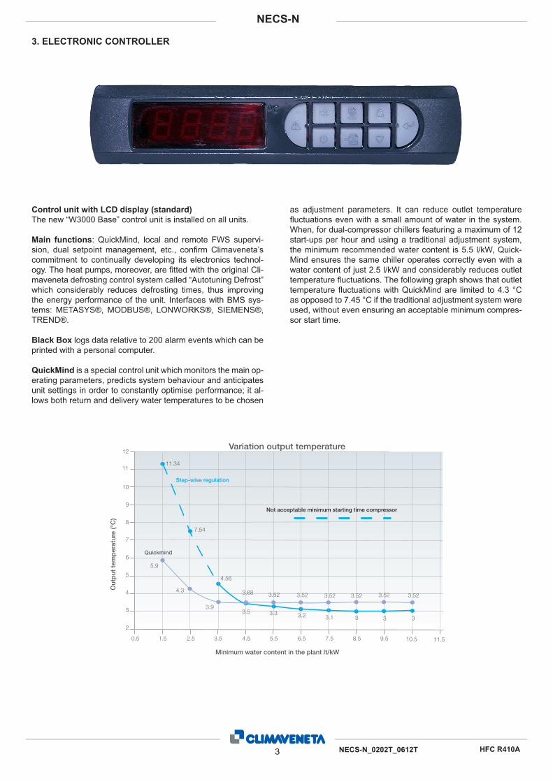
Control unit with LCD display (standard)The new “W3000 Base” control unit is installed on all units.
Main functions: QuickMind, local and remote FWS supervi-sion, dual setpoint management, etc., confirm Climaveneta’s commitment to continually developing its electronics technol-ogy. The heat pumps, moreover, are fitted with the original Cli-maveneta defrosting control system called “Autotuning Defrost” which considerably reduces defrosting times, thus improving the energy performance of the unit. Interfaces with BMS sys-tems: METASYS®, MODBUS®, LONWORKS®, SIEMENS®, TREND®.
Black Box logs data relative to 200 alarm events which can be printed with a personal computer.
QuickMind is a special control unit which monitors the main op-erating parameters, predicts system behaviour and anticipates unit settings in order to constantly optimise performance; it al-lows both return and delivery water temperatures to be chosen
as adjustment parameters. It can reduce outlet temperature fluctuations even with a small amount of water in the system. When, for dual-compressor chillers featuring a maximum of 12 start-ups per hour and using a traditional adjustment system, the minimum recommended water content is 5.5 l/kW, Quick-Mind ensures the same chiller operates correctly even with a water content of just 2.5 l/kW and considerably reduces outlet temperature fluctuations. The following graph shows that outlet temperature fluctuations with QuickMind are limited to 4.3 °C as opposed to 7.45 °C if the traditional adjustment system were used, without even ensuring an acceptable minimum compres-sor start time.
3. ELECTRONIC CONTROLLER
2
3
5
4
65.9
4.56
7.54
11.34
3 3
3.93.3 3.2 3.1
7
8
10
9
Out
put
tem
per
atur
e (°
C)
Variation output temperature
11
12
0.5 1.5 2.5 3.5 4.5 5.5 6.5 7.5 8.5 9.5
4.3
3.53
Minimum water content in the plant lt/kW
11.510.5
3.52 3.52 3.52 3.52 3.523,68 3.52
Not acceptable minimum starting time compressor
Step-wise regulation
Quickmind
4 NECS-N_0202T_0612T
NECS-N
HFC R410A
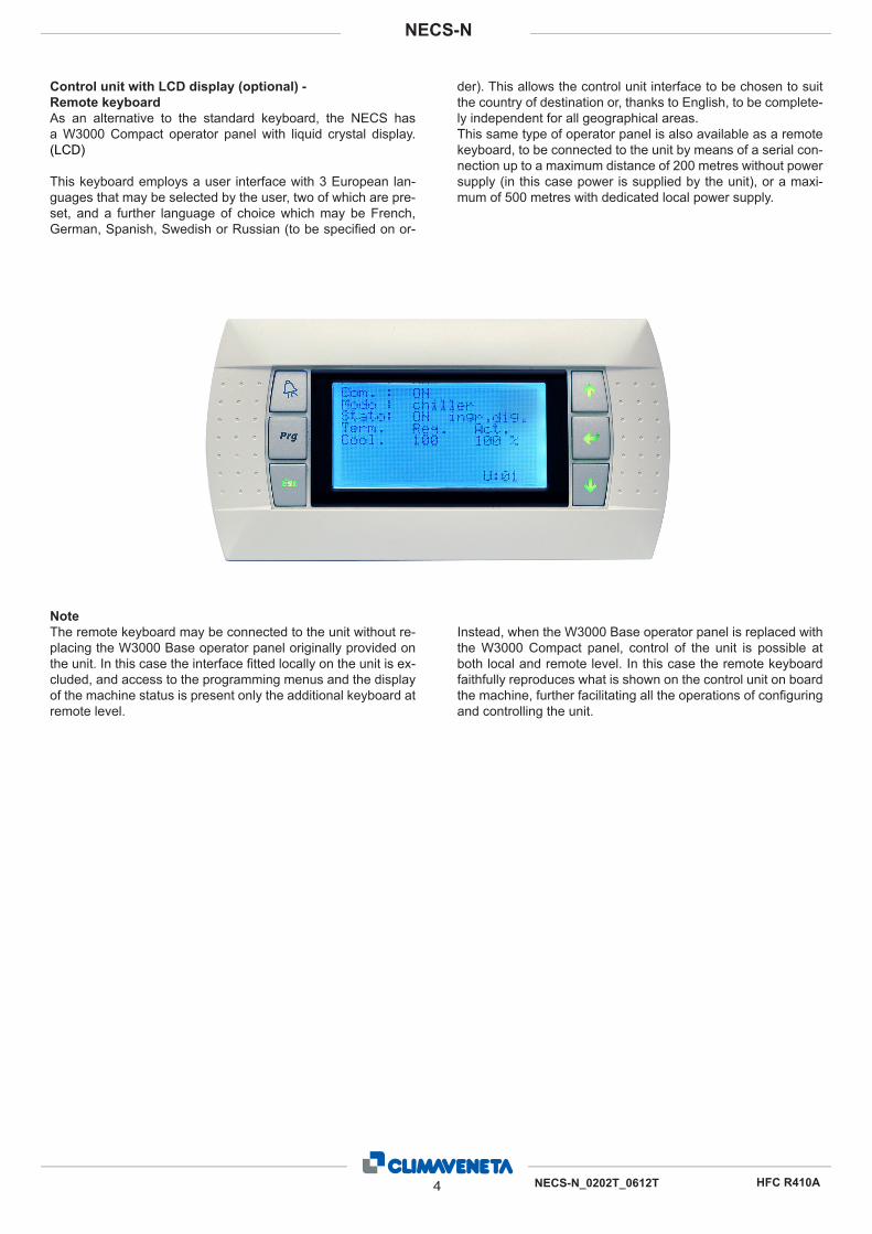
Control unit with LCD display (optional) - Remote keyboardAs an alternative to the standard keyboard, the NECS has a W3000 Compact operator panel with liquid crystal display. (LCD)
This keyboard employs a user interface with 3 European lan-guages that may be selected by the user, two of which are pre-set, and a further language of choice which may be French, German, Spanish, Swedish or Russian (to be specified on or-
der). This allows the control unit interface to be chosen to suit the country of destination or, thanks to English, to be complete-ly independent for all geographical areas.This same type of operator panel is also available as a remote keyboard, to be connected to the unit by means of a serial con-nection up to a maximum distance of 200 metres without power supply (in this case power is supplied by the unit), or a maxi-mum of 500 metres with dedicated local power supply.
NoteThe remote keyboard may be connected to the unit without re-placing the W3000 Base operator panel originally provided on the unit. In this case the interface fitted locally on the unit is ex-cluded, and access to the programming menus and the display of the machine status is present only the additional keyboard at remote level.
Instead, when the W3000 Base operator panel is replaced with the W3000 Compact panel, control of the unit is possible at both local and remote level. In this case the remote keyboard faithfully reproduces what is shown on the control unit on board the machine, further facilitating all the operations of configuring and controlling the unit.
NECS-N 0202T-0612T5
NECS-N / B4.1 GENERAL TECHNICAL DATA
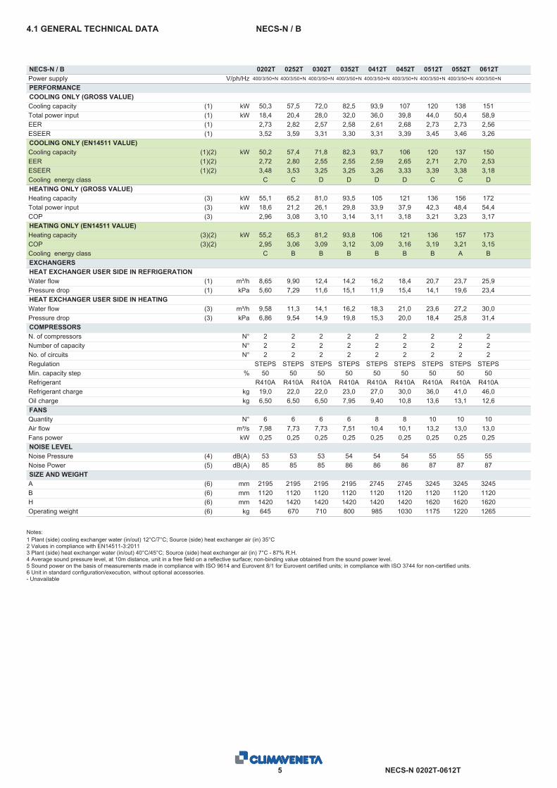
NECS-N / B 0202T 0252T 0302T 0352T 0412T 0452T 0512T 0552T 0612TPower supply V/ph/Hz 400/3/50+N 400/3/50+N 400/3/50+N 400/3/50+N 400/3/50+N 400/3/50+N 400/3/50+N 400/3/50+N 400/3/50+N
PERFORMANCECOOLING ONLY (GROSS VALUE)Cooling capacity (1) kW 50,3 57,5 72,0 82,5 93,9 107 120 138 151Total power input (1) kW 18,4 20,4 28,0 32,0 36,0 39,8 44,0 50,4 58,9EER (1) 2,73 2,82 2,57 2,58 2,61 2,68 2,73 2,73 2,56ESEER (1) 3,52 3,59 3,31 3,30 3,31 3,39 3,45 3,46 3,26COOLING ONLY (EN14511 VALUE)Cooling capacity (1)(2) kW 50,2 57,4 71,8 82,3 93,7 106 120 137 150EER (1)(2) 2,72 2,80 2,55 2,55 2,59 2,65 2,71 2,70 2,53ESEER (1)(2) 3,48 3,53 3,25 3,25 3,26 3,33 3,39 3,38 3,18Cooling energy class C C D D D D C C DHEATING ONLY (GROSS VALUE)Heating capacity (3) kW 55,1 65,2 81,0 93,5 105 121 136 156 172Total power input (3) kW 18,6 21,2 26,1 29,8 33,9 37,9 42,3 48,4 54,4COP (3) 2,96 3,08 3,10 3,14 3,11 3,18 3,21 3,23 3,17HEATING ONLY (EN14511 VALUE)Heating capacity (3)(2) kW 55,2 65,3 81,2 93,8 106 121 136 157 173COP (3)(2) 2,95 3,06 3,09 3,12 3,09 3,16 3,19 3,21 3,15Cooling energy class C B B B B B B A BEXCHANGERSHEAT EXCHANGER USER SIDE IN REFRIGERATIONWater flow (1) m³/h 8,65 9,90 12,4 14,2 16,2 18,4 20,7 23,7 25,9Pressure drop (1) kPa 5,60 7,29 11,6 15,1 11,9 15,4 14,1 19,6 23,4HEAT EXCHANGER USER SIDE IN HEATINGWater flow (3) m³/h 9,58 11,3 14,1 16,2 18,3 21,0 23,6 27,2 30,0Pressure drop (3) kPa 6,86 9,54 14,9 19,8 15,3 20,0 18,4 25,8 31,4COMPRESSORSN. of compressors N° 2 2 2 2 2 2 2 2 2Number of capacity N° 2 2 2 2 2 2 2 2 2No. of circuits N° 2 2 2 2 2 2 2 2 2Regulation STEPS STEPS STEPS STEPS STEPS STEPS STEPS STEPS STEPSMin. capacity step % 50 50 50 50 50 50 50 50 50Refrigerant R410A R410A R410A R410A R410A R410A R410A R410A R410ARefrigerant charge kg 19,0 22,0 22,0 23,0 27,0 30,0 36,0 41,0 46,0Oil charge kg 6,50 6,50 6,50 7,95 9,40 10,8 13,6 13,1 12,6FANSQuantity N° 6 6 6 6 8 8 10 10 10Air flow m³/s 7,98 7,73 7,73 7,51 10,4 10,1 13,2 13,0 13,0Fans power kW 0,25 0,25 0,25 0,25 0,25 0,25 0,25 0,25 0,25NOISE LEVELNoise Pressure (4) dB(A) 53 53 53 54 54 54 55 55 55Noise Power (5) dB(A) 85 85 85 86 86 86 87 87 87SIZE AND WEIGHTA (6) mm 2195 2195 2195 2195 2745 2745 3245 3245 3245B (6) mm 1120 1120 1120 1120 1120 1120 1120 1120 1120H (6) mm 1420 1420 1420 1420 1420 1420 1620 1620 1620Operating weight (6) kg 645 670 710 800 985 1030 1175 1220 1265
Notes:1 Plant (side) cooling exchanger water (in/out) 12°C/7°C; Source (side) heat exchanger air (in) 35°C2 Values in compliance with EN14511-3:20113 Plant (side) heat exchanger water (in/out) 40°C/45°C; Source (side) heat exchanger air (in) 7°C - 87% R.H.4 Average sound pressure level, at 10m distance, unit in a free field on a reflective surface; non-binding value obtained from the sound power level.5 Sound power on the basis of measurements made in compliance with ISO 9614 and Eurovent 8/1 for Eurovent certified units; in compliance with ISO 3744 for non-certified units.6 Unit in standard configuration/execution, without optional accessories.- Unavailable

NECS-N 0202T-0612T6
NECS-N / LNGENERAL TECHNICAL DATA
NECS-N / LN 0202T 0252T 0302T 0352T 0412T 0452T 0512T 0552T 0612TPower supply V/ph/Hz 400/3/50+N 400/3/50+N 400/3/50+N 400/3/50+N 400/3/50+N 400/3/50+N 400/3/50+N 400/3/50+N 400/3/50+N
PERFORMANCECOOLING ONLY (GROSS VALUE)Cooling capacity (1) kW 48,0 54,6 73,2 83,5 93,9 103 119 132 143Total power input (1) kW 19,0 21,3 27,2 31,9 36,0 41,6 44,6 53,3 62,7EER (1) 2,53 2,56 2,69 2,62 2,61 2,48 2,67 2,47 2,28ESEER (1) 3,52 3,31 3,46 3,33 3,33 3,17 3,38 3,16 2,93COOLING ONLY (EN14511 VALUE)Cooling capacity (1)(2) kW 47,9 54,5 73,0 83,3 93,7 103 119 131 143EER (1)(2) 2,51 2,55 2,67 2,59 2,59 2,46 2,64 2,45 2,26ESEER (1)(2) 3,26 3,26 3,39 3,27 3,27 3,11 3,32 3,11 2,88Cooling energy class D D D D D E D E FHEATING ONLY (GROSS VALUE)Heating capacity (3) kW 54,1 63,6 84,1 96,2 109 121 138 154 169Total power input (3) kW 18,1 20,6 26,1 30,4 34,1 37,9 42,4 48,3 54,3COP (3) 2,99 3,09 3,22 3,16 3,19 3,18 3,24 3,19 3,12HEATING ONLY (EN14511 VALUE)Heating capacity (3)(2) kW 54,2 63,7 84,3 96,5 109 121 138 154 170COP (3)(2) 2,98 3,07 3,20 3,14 3,18 3,16 3,22 3,16 3,10Cooling energy class C B A B B B A B BEXCHANGERSHEAT EXCHANGER USER SIDE IN REFRIGERATIONWater flow (1) m³/h 8,26 9,41 12,6 14,4 16,2 17,8 20,5 22,7 24,6Pressure drop (1) kPa 5,11 6,58 11,9 15,5 11,9 14,4 13,8 17,9 21,2HEAT EXCHANGER USER SIDE IN HEATINGWater flow (3) m³/h 9,39 11,1 14,6 16,7 18,9 21,0 23,9 26,7 29,4Pressure drop (3) kPa 6,60 9,09 16,1 20,9 16,4 20,0 18,8 25,0 30,2COMPRESSORSN. of compressors N° 2 2 2 2 2 2 2 2 2Number of capacity N° 2 2 2 2 2 2 2 2 2No. of circuits N° 2 2 2 2 2 2 2 2 2Regulation STEPS STEPS STEPS STEPS STEPS STEPS STEPS STEPS STEPSMin. capacity step % 50 50 50 50 50 50 50 50 50Refrigerant R410A R410A R410A R410A R410A R410A R410A R410A R410ARefrigerant charge kg 19,0 22,0 25,0 35,0 38,0 34,0 49,0 41,0 46,0Oil charge kg 6,00 6,50 6,50 7,95 9,40 10,8 13,6 13,1 12,6FANSQuantity N° 6 6 8 8 8 8 10 10 10Air flow m³/s 6,12 5,81 7,85 8,85 8,68 8,68 10,9 10,9 10,9Fans power kW 0,16 0,16 0,16 0,25 0,25 0,25 0,25 0,25 0,25NOISE LEVELNoise Pressure (4) dB(A) 48 48 49 51 51 51 52 52 52Noise Power (5) dB(A) 80 80 81 83 83 83 84 84 84SIZE AND WEIGHTA (6) mm 2195 2195 2745 2745 2745 2745 3245 3245 3245B (6) mm 1120 1120 1120 1120 1120 1120 1120 1120 1120H (6) mm 1420 1420 1420 1620 1620 1620 1620 1620 1620Operating weight (6) kg 645 670 795 935 1060 1065 1230 1220 1265
Notes:1 Plant (side) cooling exchanger water (in/out) 12°C/7°C; Source (side) heat exchanger air (in) 35°C2 Values in compliance with EN14511-3:20113 Plant (side) heat exchanger water (in/out) 40°C/45°C; Source (side) heat exchanger air (in) 7°C - 87% R.H.4 Average sound pressure level, at 10m distance, unit in a free field on a reflective surface; non-binding value obtained from the sound power level.5 Sound power on the basis of measurements made in compliance with ISO 9614 and Eurovent 8/1 for Eurovent certified units; in compliance with ISO 3744 for non-certified units.6 Unit in standard configuration/execution, without optional accessories.- Unavailable
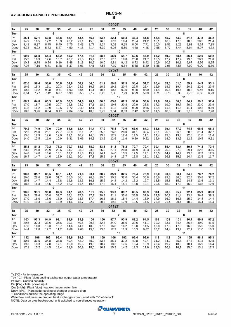
BNECS-N4.2 COOLING CAPACITY PERFORMANCE
0202T30 32 35 40 42 25 25 30 32 35 40 42 25 30 32 35 40 42
6 7 8 Tev Pf Pat Qev Dpev
55,1 52,1 50,8 48,8 45,1 43,5 56,7 53,7 52,4 50,3 46,4 44,8 58,4 55,2 53,9 51,7 47,8 46,214,9 16,5 17,2 18,3 20,2 21,1 15,0 16,6 17,3 18,4 20,4 21,2 15,1 16,8 17,5 18,6 20,5 21,49,49 8,97 8,75 8,40 7,75 7,48 9,77 9,24 9,02 8,65 8,00 7,71 10,0 9,51 9,28 8,91 8,24 7,956,73 6,02 5,73 5,27 4,50 4,18 7,14 6,39 6,08 5,60 4,78 4,45 7,55 6,77 6,44 5,94 5,07 4,72
Ta
Dpev 7,98 7,16 6,81 6,28 5,37 5,01 8,41 7,55 7,19 6,64 5,68 5,30 8,86 7,96 7,58 7,00 6,00 5,60Qev 10,3 9,78 9,54 9,16 8,48 8,18 10,6 10,0 9,81 9,42 8,72 8,42 10,9 10,3 10,1 9,67 8,96 8,65Pat 15,3 16,9 17,6 18,7 20,7 21,5 15,4 17,0 17,7 18,8 20,8 21,7 15,5 17,2 17,9 19,0 20,9 21,8Pf 60,0 56,8 55,4 53,2 49,2 47,5 61,6 58,3 56,9 54,7 50,6 48,9 63,2 59,9 58,4 56,1 52,0 50,2
9 10 11 Tev
0252T30 32 35 40 42 25 25 30 32 35 40 42 25 30 32 35 40 42
6 7 8 Tev Pf Pat Qev Dpev
62,6 59,4 58,0 55,8 51,9 50,2 64,5 61,2 59,8 57,5 53,4 51,7 66,4 63,0 61,5 59,2 54,9 53,116,6 18,3 19,1 20,3 22,4 23,3 16,8 18,5 19,2 20,4 22,5 23,4 16,9 18,6 19,4 20,5 22,6 23,510,8 10,2 9,98 9,61 8,93 8,64 11,1 10,5 10,3 9,90 9,20 8,90 11,4 10,8 10,6 10,2 9,46 9,158,64 7,77 7,42 6,87 5,93 5,55 9,17 8,26 7,88 7,29 6,29 5,89 9,71 8,75 8,35 7,73 6,66 6,23
Ta
Dpev 10,3 9,26 8,84 8,17 7,04 6,57 10,9 9,79 9,34 8,63 7,42 6,92 11,5 10,3 9,85 9,10 7,81 7,28Qev 11,8 11,2 10,9 10,5 9,72 9,40 12,1 11,5 11,2 10,8 9,99 9,65 12,4 11,8 11,5 11,1 10,2 9,89Pat 17,0 18,7 19,5 20,7 22,8 23,7 17,1 18,9 19,6 20,8 22,9 23,8 17,3 19,0 19,7 20,9 23,0 23,9Pf 68,2 64,8 63,3 60,9 56,5 54,6 70,1 66,6 65,0 62,5 58,0 56,0 72,0 68,4 66,8 64,2 59,5 57,4
9 10 11 Tev
0302T30 32 35 40 42 25 25 30 32 35 40 42 25 30 32 35 40 42
6 7 8 Tev Pf Pat Qev Dpev
79,2 74,9 73,0 70,0 64,6 62,4 81,4 77,0 75,1 72,0 66,6 64,3 83,6 79,1 77,2 74,1 68,6 66,322,6 25,0 26,1 27,7 30,8 32,1 22,8 25,3 26,3 28,0 31,1 32,4 23,1 25,5 26,6 28,3 31,4 32,713,6 12,9 12,6 12,0 11,1 10,7 14,0 13,3 12,9 12,4 11,5 11,1 14,4 13,6 13,3 12,8 11,8 11,414,0 12,5 11,9 10,9 9,31 8,66 14,8 13,2 12,6 11,6 9,89 9,22 15,6 14,0 13,3 12,2 10,5 9,81
Ta
Dpev 16,4 14,7 14,0 12,9 11,1 10,4 17,3 15,5 14,8 13,7 11,8 11,1 18,1 16,3 15,5 14,4 12,5 11,7Qev 14,8 14,0 13,6 13,1 12,2 11,8 15,2 14,4 14,0 13,5 12,5 12,1 15,5 14,7 14,4 13,8 12,9 12,5Pat 23,3 25,8 26,9 28,6 31,7 33,0 23,5 26,0 27,1 28,8 31,9 33,3 23,8 26,3 27,3 29,1 32,2 33,5Pf 85,8 81,2 79,2 76,2 70,7 68,3 88,0 83,3 81,3 78,2 72,7 70,4 90,1 85,4 83,4 80,3 74,8 72,4
9 10 11 Tev
0352T30 32 35 40 42 25 25 30 32 35 40 42 25 30 32 35 40 42
6 7 8 Tev Pf Pat Qev Dpev
90,8 85,7 83,5 80,1 74,1 71,6 93,4 88,2 85,9 82,5 76,4 73,9 96,0 90,6 88,4 84,9 78,7 76,226,0 28,6 29,8 31,7 35,0 36,4 26,3 29,0 30,2 32,0 35,4 36,8 26,6 29,3 30,5 32,4 35,8 37,215,6 14,7 14,4 13,8 12,8 12,3 16,1 15,2 14,8 14,2 13,2 12,7 16,5 15,6 15,2 14,6 13,6 13,118,3 16,3 15,5 14,2 12,2 11,4 19,4 17,2 16,4 15,1 13,0 12,1 20,5 18,2 17,3 16,0 13,8 12,9
Ta
Dpev 21,6 19,3 18,3 16,9 14,6 13,7 22,7 20,3 19,3 17,9 15,5 14,5 23,9 21,4 20,4 18,9 16,4 15,4Qev 17,0 16,0 15,6 15,0 14,0 13,5 17,4 16,5 16,1 15,4 14,4 13,9 17,9 16,9 16,5 15,9 14,8 14,4Pat 26,9 29,6 30,8 32,7 36,1 37,6 27,2 29,9 31,1 33,0 36,5 37,9 27,5 30,2 31,4 33,4 36,8 38,3Pf 98,6 93,1 90,8 87,3 81,1 78,5 101 95,6 93,3 89,7 83,5 80,9 104 98,0 95,7 92,1 85,9 83,3
9 10 11 Tev
0412T30 32 35 40 42 25 25 30 32 35 40 42 25 30 32 35 40 42
6 7 8 Tev Pf Pat Qev Dpev
103 97,3 94,9 91,1 84,6 81,9 106 100 97,7 93,9 87,2 84,5 109 103 101 96,7 89,9 87,229,5 32,3 33,6 35,6 39,1 40,6 29,8 32,7 34,0 36,0 39,6 41,1 30,2 33,1 34,4 36,4 40,0 41,517,8 16,8 16,3 15,7 14,6 14,1 18,3 17,3 16,8 16,2 15,0 14,5 18,8 17,8 17,3 16,6 15,5 15,014,4 12,8 12,2 11,2 9,69 9,08 15,3 13,6 12,9 11,9 10,3 9,67 16,2 14,4 13,7 12,7 11,0 10,3
Ta
Dpev 17,1 15,2 14,5 13,4 11,6 10,9 18,0 16,1 15,3 14,2 12,3 11,6 19,0 16,9 16,1 15,0 13,1 12,3Qev 19,3 18,3 17,8 17,1 16,0 15,5 19,8 18,7 18,3 17,6 16,4 15,9 20,4 19,2 18,8 18,1 16,9 16,4Pat 30,5 33,5 34,8 36,8 40,4 42,0 30,9 33,8 35,1 37,2 40,8 42,4 31,2 34,2 35,5 37,6 41,3 42,8Pf 112 106 103 99,4 92,6 89,9 115 109 106 102 95,4 92,6 118 112 109 105 98,1 95,3
9 10 11 Tev
Ta [°C] - Air temperature Tev [°C] - Plant (side) cooling exchanger output water temperature
Pat [kW] - Total power input Qev [m³/h] - Plant (side) heat exchanger water flow Dpev [kPa] - Plant (side) cooling exchanger pressure drop
Pf [kW] - Cooling capacity
'-' Conditions outside the operating range Waterflow and pressure drop on heat exchangers calculated with 5°C of delta TNOTE: Data on grey background: unit switched to non-silenced operation
9ELCADOC - Ver. 1.0.0.7 NECS-N_0202T_0612T_201007_GB R410A
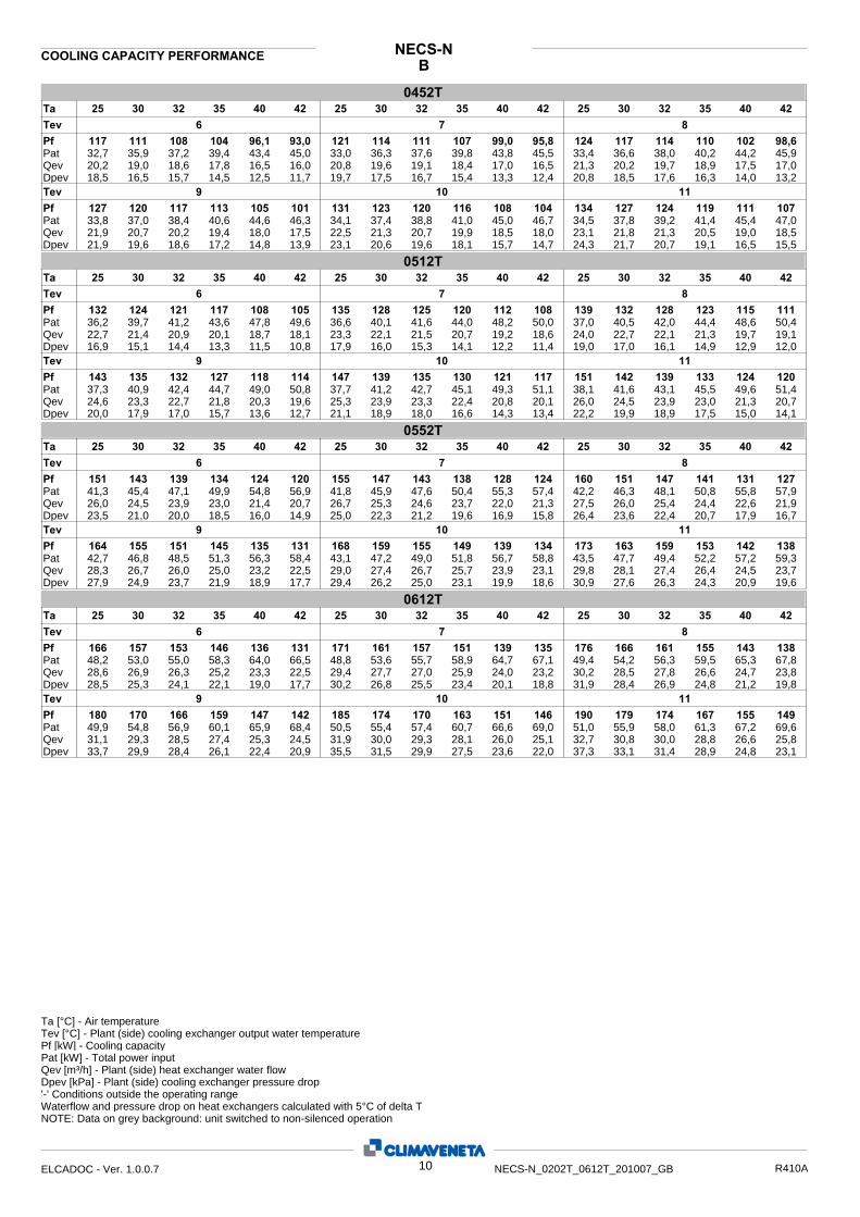
BNECS-NCOOLING CAPACITY PERFORMANCE
0452T30 32 35 40 42 25 25 30 32 35 40 42 25 30 32 35 40 42
6 7 8 Tev Pf Pat Qev Dpev
117 111 108 104 96,1 93,0 121 114 111 107 99,0 95,8 124 117 114 110 102 98,632,7 35,9 37,2 39,4 43,4 45,0 33,0 36,3 37,6 39,8 43,8 45,5 33,4 36,6 38,0 40,2 44,2 45,920,2 19,0 18,6 17,8 16,5 16,0 20,8 19,6 19,1 18,4 17,0 16,5 21,3 20,2 19,7 18,9 17,5 17,018,5 16,5 15,7 14,5 12,5 11,7 19,7 17,5 16,7 15,4 13,3 12,4 20,8 18,5 17,6 16,3 14,0 13,2
Ta
Dpev 21,9 19,6 18,6 17,2 14,8 13,9 23,1 20,6 19,6 18,1 15,7 14,7 24,3 21,7 20,7 19,1 16,5 15,5Qev 21,9 20,7 20,2 19,4 18,0 17,5 22,5 21,3 20,7 19,9 18,5 18,0 23,1 21,8 21,3 20,5 19,0 18,5Pat 33,8 37,0 38,4 40,6 44,6 46,3 34,1 37,4 38,8 41,0 45,0 46,7 34,5 37,8 39,2 41,4 45,4 47,0Pf 127 120 117 113 105 101 131 123 120 116 108 104 134 127 124 119 111 107
9 10 11 Tev
0512T30 32 35 40 42 25 25 30 32 35 40 42 25 30 32 35 40 42
6 7 8 Tev Pf Pat Qev Dpev
132 124 121 117 108 105 135 128 125 120 112 108 139 132 128 123 115 11136,2 39,7 41,2 43,6 47,8 49,6 36,6 40,1 41,6 44,0 48,2 50,0 37,0 40,5 42,0 44,4 48,6 50,422,7 21,4 20,9 20,1 18,7 18,1 23,3 22,1 21,5 20,7 19,2 18,6 24,0 22,7 22,1 21,3 19,7 19,116,9 15,1 14,4 13,3 11,5 10,8 17,9 16,0 15,3 14,1 12,2 11,4 19,0 17,0 16,1 14,9 12,9 12,0
Ta
Dpev 20,0 17,9 17,0 15,7 13,6 12,7 21,1 18,9 18,0 16,6 14,3 13,4 22,2 19,9 18,9 17,5 15,0 14,1Qev 24,6 23,3 22,7 21,8 20,3 19,6 25,3 23,9 23,3 22,4 20,8 20,1 26,0 24,5 23,9 23,0 21,3 20,7Pat 37,3 40,9 42,4 44,7 49,0 50,8 37,7 41,2 42,7 45,1 49,3 51,1 38,1 41,6 43,1 45,5 49,6 51,4Pf 143 135 132 127 118 114 147 139 135 130 121 117 151 142 139 133 124 120
9 10 11 Tev
0552T30 32 35 40 42 25 25 30 32 35 40 42 25 30 32 35 40 42
6 7 8 Tev Pf Pat Qev Dpev
151 143 139 134 124 120 155 147 143 138 128 124 160 151 147 141 131 12741,3 45,4 47,1 49,9 54,8 56,9 41,8 45,9 47,6 50,4 55,3 57,4 42,2 46,3 48,1 50,8 55,8 57,926,0 24,5 23,9 23,0 21,4 20,7 26,7 25,3 24,6 23,7 22,0 21,3 27,5 26,0 25,4 24,4 22,6 21,923,5 21,0 20,0 18,5 16,0 14,9 25,0 22,3 21,2 19,6 16,9 15,8 26,4 23,6 22,4 20,7 17,9 16,7
Ta
Dpev 27,9 24,9 23,7 21,9 18,9 17,7 29,4 26,2 25,0 23,1 19,9 18,6 30,9 27,6 26,3 24,3 20,9 19,6Qev 28,3 26,7 26,0 25,0 23,2 22,5 29,0 27,4 26,7 25,7 23,9 23,1 29,8 28,1 27,4 26,4 24,5 23,7Pat 42,7 46,8 48,5 51,3 56,3 58,4 43,1 47,2 49,0 51,8 56,7 58,8 43,5 47,7 49,4 52,2 57,2 59,3Pf 164 155 151 145 135 131 168 159 155 149 139 134 173 163 159 153 142 138
9 10 11 Tev
0612T30 32 35 40 42 25 25 30 32 35 40 42 25 30 32 35 40 42
6 7 8 Tev Pf Pat Qev Dpev
166 157 153 146 136 131 171 161 157 151 139 135 176 166 161 155 143 13848,2 53,0 55,0 58,3 64,0 66,5 48,8 53,6 55,7 58,9 64,7 67,1 49,4 54,2 56,3 59,5 65,3 67,828,6 26,9 26,3 25,2 23,3 22,5 29,4 27,7 27,0 25,9 24,0 23,2 30,2 28,5 27,8 26,6 24,7 23,828,5 25,3 24,1 22,1 19,0 17,7 30,2 26,8 25,5 23,4 20,1 18,8 31,9 28,4 26,9 24,8 21,2 19,8
Ta
Dpev 33,7 29,9 28,4 26,1 22,4 20,9 35,5 31,5 29,9 27,5 23,6 22,0 37,3 33,1 31,4 28,9 24,8 23,1Qev 31,1 29,3 28,5 27,4 25,3 24,5 31,9 30,0 29,3 28,1 26,0 25,1 32,7 30,8 30,0 28,8 26,6 25,8Pat 49,9 54,8 56,9 60,1 65,9 68,4 50,5 55,4 57,4 60,7 66,6 69,0 51,0 55,9 58,0 61,3 67,2 69,6Pf 180 170 166 159 147 142 185 174 170 163 151 146 190 179 174 167 155 149
9 10 11 Tev
Ta [°C] - Air temperature Tev [°C] - Plant (side) cooling exchanger output water temperature
Pat [kW] - Total power input Qev [m³/h] - Plant (side) heat exchanger water flow Dpev [kPa] - Plant (side) cooling exchanger pressure drop
Pf [kW] - Cooling capacity
'-' Conditions outside the operating range Waterflow and pressure drop on heat exchangers calculated with 5°C of delta TNOTE: Data on grey background: unit switched to non-silenced operation
10ELCADOC - Ver. 1.0.0.7 NECS-N_0202T_0612T_201007_GB R410A

LNNECS-NCOOLING CAPACITY PERFORMANCE
0202T30 32 35 40 42 25 25 30 32 35 40 42 25 30 32 35 40 42
6 7 8 Tev Pf Pat Qev Dpev
53,4 50,2 48,8 46,6 42,7 41,0 54,9 51,7 50,2 48,0 43,9 42,2 56,5 53,1 51,7 49,4 45,2 43,515,3 17,0 17,7 18,9 20,9 21,8 15,4 17,2 17,9 19,0 21,1 22,0 15,6 17,3 18,1 19,2 21,3 22,29,19 8,64 8,40 8,02 7,34 7,05 9,46 8,89 8,65 8,26 7,57 7,27 9,72 9,15 8,90 8,50 7,79 7,486,32 5,58 5,28 4,82 4,03 3,72 6,69 5,92 5,60 5,11 4,28 3,95 7,07 6,26 5,92 5,41 4,54 4,19
Ta
Dpev 7,46 6,61 6,25 5,71 4,80 4,43 7,86 6,97 6,59 6,03 5,07 4,68 8,27 7,33 6,94 6,35 5,34 4,94Qev 9,99 9,40 9,14 8,74 8,01 7,70 10,3 9,65 9,39 8,98 8,23 7,91 10,5 9,90 9,63 9,21 8,45 8,12Pat 15,7 17,5 18,2 19,4 21,5 22,3 15,9 17,6 18,4 19,6 21,6 22,5 16,0 17,8 18,5 19,7 21,8 22,7Pf 58,0 54,6 53,1 50,7 46,5 44,7 59,5 56,0 54,5 52,1 47,8 45,9 61,0 57,5 55,9 53,5 49,0 47,1
9 10 11 Tev
0252T30 32 35 40 42 25 25 30 32 35 40 42 25 30 32 35 40 42
6 7 8 Tev Pf Pat Qev Dpev
60,4 56,9 55,5 53,1 48,9 47,1 62,2 58,6 57,1 54,6 50,2 48,4 63,9 60,3 58,7 56,1 51,6 49,617,3 19,1 19,9 21,2 23,4 24,4 17,4 19,3 20,1 21,3 23,6 24,5 17,6 19,5 20,3 21,5 23,7 24,710,4 9,80 9,54 9,14 8,42 8,11 10,7 10,1 9,82 9,41 8,65 8,33 11,0 10,4 10,1 9,67 8,88 8,548,04 7,15 6,78 6,22 5,27 4,89 8,52 7,57 7,18 6,58 5,57 5,16 9,02 8,01 7,59 6,95 5,87 5,43
Ta
Dpev 9,52 8,46 8,01 7,33 6,17 5,70 10,0 8,92 8,44 7,72 6,48 5,98 10,6 9,39 8,88 8,11 6,78 6,25Qev 11,3 10,7 10,4 9,93 9,11 8,76 11,6 10,9 10,7 10,2 9,33 8,96 11,9 11,2 10,9 10,4 9,55 9,16Pat 17,7 19,6 20,4 21,7 23,9 24,8 17,9 19,8 20,5 21,8 24,0 25,0 18,0 19,9 20,7 21,9 24,2 25,1Pf 65,7 61,9 60,3 57,6 52,9 50,8 67,5 63,5 61,8 59,1 54,2 52,0 69,2 65,2 63,4 60,6 55,4 53,2
9 10 11 Tev
0302T30 32 35 40 42 25 25 30 32 35 40 42 25 30 32 35 40 42
6 7 8 Tev Pf Pat Qev Dpev
80,1 75,9 74,0 71,1 65,8 63,5 82,4 78,0 76,1 73,2 67,8 65,5 84,6 80,2 78,3 75,3 69,8 67,521,9 24,2 25,3 26,9 29,9 31,2 22,1 24,5 25,5 27,2 30,2 31,5 22,3 24,7 25,8 27,4 30,5 31,813,8 13,1 12,7 12,2 11,3 10,9 14,2 13,4 13,1 12,6 11,7 11,3 14,6 13,8 13,5 13,0 12,0 11,614,3 12,8 12,2 11,3 9,65 8,99 15,1 13,6 12,9 11,9 10,2 9,57 16,0 14,3 13,7 12,6 10,9 10,2
Ta
Dpev 16,8 15,1 14,4 13,3 11,5 10,8 17,7 15,9 15,2 14,1 12,2 11,5 18,6 16,7 16,0 14,8 12,9 12,1Qev 15,0 14,2 13,8 13,3 12,4 12,0 15,3 14,6 14,2 13,7 12,7 12,3 15,7 14,9 14,6 14,0 13,1 12,7Pat 22,5 25,0 26,0 27,7 30,7 32,1 22,8 25,2 26,2 27,9 31,0 32,3 23,0 25,4 26,5 28,1 31,2 32,6Pf 86,9 82,3 80,4 77,3 71,9 69,6 89,1 84,5 82,5 79,4 74,0 71,7 91,3 86,6 84,6 81,5 76,0 73,7
9 10 11 Tev
0352T30 32 35 40 42 25 25 30 32 35 40 42 25 30 32 35 40 42
6 7 8 Tev Pf Pat Qev Dpev
91,8 86,6 84,5 81,1 75,2 72,7 94,4 89,2 86,9 83,5 77,5 75,0 97,0 91,7 89,4 86,0 79,9 77,326,0 28,6 29,8 31,6 34,9 36,3 26,3 29,0 30,1 31,9 35,3 36,7 26,6 29,3 30,4 32,3 35,6 37,115,8 14,9 14,5 14,0 12,9 12,5 16,3 15,3 15,0 14,4 13,3 12,9 16,7 15,8 15,4 14,8 13,8 13,318,7 16,7 15,8 14,6 12,5 11,7 19,8 17,6 16,8 15,5 13,3 12,5 20,9 18,7 17,8 16,4 14,2 13,3
Ta
Dpev 22,1 19,7 18,8 17,4 15,0 14,1 23,2 20,8 19,8 18,3 15,9 15,0 24,4 21,9 20,9 19,3 16,9 15,9Qev 17,2 16,2 15,8 15,2 14,2 13,7 17,6 16,7 16,3 15,6 14,6 14,1 18,1 17,1 16,7 16,1 15,0 14,6Pat 26,9 29,6 30,7 32,6 36,0 37,4 27,2 29,9 31,0 32,9 36,3 37,7 27,4 30,2 31,3 33,2 36,6 38,1Pf 99,6 94,2 91,9 88,4 82,2 79,7 102 96,7 94,4 90,8 84,6 82,1 105 99,2 96,9 93,3 87,1 84,5
9 10 11 Tev
0412T30 32 35 40 42 25 25 30 32 35 40 42 25 30 32 35 40 42
6 7 8 Tev Pf Pat Qev Dpev
103 97,4 94,9 91,1 84,5 81,8 106 100 97,8 93,9 87,2 84,4 109 103 101 96,7 89,9 87,129,4 32,3 33,5 35,5 39,1 40,7 29,8 32,7 33,9 36,0 39,6 41,1 30,1 33,1 34,3 36,4 40,0 41,617,8 16,8 16,3 15,7 14,5 14,1 18,3 17,3 16,8 16,2 15,0 14,5 18,8 17,8 17,3 16,6 15,5 15,014,5 12,8 12,2 11,2 9,67 9,06 15,3 13,6 12,9 11,9 10,3 9,65 16,2 14,4 13,7 12,7 10,9 10,3
Ta
Dpev 17,1 15,3 14,5 13,4 11,6 10,9 18,1 16,1 15,3 14,2 12,3 11,6 19,0 17,0 16,2 15,0 13,0 12,3Qev 19,4 18,3 17,8 17,1 15,9 15,5 19,9 18,8 18,3 17,6 16,4 15,9 20,4 19,3 18,8 18,1 16,9 16,4Pat 30,4 33,4 34,7 36,8 40,5 42,0 30,8 33,8 35,1 37,2 40,9 42,5 31,1 34,1 35,5 37,5 41,3 42,9Pf 112 106 103 99,5 92,6 89,8 115 109 106 102 95,3 92,5 118 112 109 105 98,1 95,2
9 10 11 Tev
Ta [°C] - Air temperature Tev [°C] - Plant (side) cooling exchanger output water temperature
Pat [kW] - Total power input Qev [m³/h] - Plant (side) heat exchanger water flow Dpev [kPa] - Plant (side) cooling exchanger pressure drop
Pf [kW] - Cooling capacity
'-' Conditions outside the operating range Waterflow and pressure drop on heat exchangers calculated with 5°C of delta TNOTE: Data on grey background: unit switched to non-silenced operation
11ELCADOC - Ver. 1.0.0.7 NECS-N_0202T_0612T_201007_GB R410A
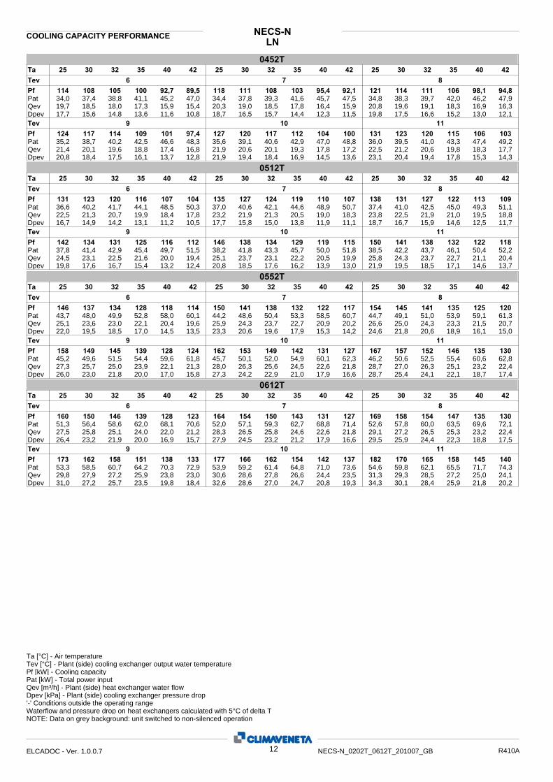
LNNECS-NCOOLING CAPACITY PERFORMANCE
0452T30 32 35 40 42 25 25 30 32 35 40 42 25 30 32 35 40 42
6 7 8 Tev Pf Pat Qev Dpev
114 108 105 100 92,7 89,5 118 111 108 103 95,4 92,1 121 114 111 106 98,1 94,834,0 37,4 38,8 41,1 45,2 47,0 34,4 37,8 39,3 41,6 45,7 47,5 34,8 38,3 39,7 42,0 46,2 47,919,7 18,5 18,0 17,3 15,9 15,4 20,3 19,0 18,5 17,8 16,4 15,9 20,8 19,6 19,1 18,3 16,9 16,317,7 15,6 14,8 13,6 11,6 10,8 18,7 16,5 15,7 14,4 12,3 11,5 19,8 17,5 16,6 15,2 13,0 12,1
Ta
Dpev 20,8 18,4 17,5 16,1 13,7 12,8 21,9 19,4 18,4 16,9 14,5 13,6 23,1 20,4 19,4 17,8 15,3 14,3Qev 21,4 20,1 19,6 18,8 17,4 16,8 21,9 20,6 20,1 19,3 17,8 17,2 22,5 21,2 20,6 19,8 18,3 17,7Pat 35,2 38,7 40,2 42,5 46,6 48,3 35,6 39,1 40,6 42,9 47,0 48,8 36,0 39,5 41,0 43,3 47,4 49,2Pf 124 117 114 109 101 97,4 127 120 117 112 104 100 131 123 120 115 106 103
9 10 11 Tev
0512T30 32 35 40 42 25 25 30 32 35 40 42 25 30 32 35 40 42
6 7 8 Tev Pf Pat Qev Dpev
131 123 120 116 107 104 135 127 124 119 110 107 138 131 127 122 113 10936,6 40,2 41,7 44,1 48,5 50,3 37,0 40,6 42,1 44,6 48,9 50,7 37,4 41,0 42,5 45,0 49,3 51,122,5 21,3 20,7 19,9 18,4 17,8 23,2 21,9 21,3 20,5 19,0 18,3 23,8 22,5 21,9 21,0 19,5 18,816,7 14,9 14,2 13,1 11,2 10,5 17,7 15,8 15,0 13,8 11,9 11,1 18,7 16,7 15,9 14,6 12,5 11,7
Ta
Dpev 19,8 17,6 16,7 15,4 13,2 12,4 20,8 18,5 17,6 16,2 13,9 13,0 21,9 19,5 18,5 17,1 14,6 13,7Qev 24,5 23,1 22,5 21,6 20,0 19,4 25,1 23,7 23,1 22,2 20,5 19,9 25,8 24,3 23,7 22,7 21,1 20,4Pat 37,8 41,4 42,9 45,4 49,7 51,5 38,2 41,8 43,3 45,7 50,0 51,8 38,5 42,2 43,7 46,1 50,4 52,2Pf 142 134 131 125 116 112 146 138 134 129 119 115 150 141 138 132 122 118
9 10 11 Tev
0552T30 32 35 40 42 25 25 30 32 35 40 42 25 30 32 35 40 42
6 7 8 Tev Pf Pat Qev Dpev
146 137 134 128 118 114 150 141 138 132 122 117 154 145 141 135 125 12043,7 48,0 49,9 52,8 58,0 60,1 44,2 48,6 50,4 53,3 58,5 60,7 44,7 49,1 51,0 53,9 59,1 61,325,1 23,6 23,0 22,1 20,4 19,6 25,9 24,3 23,7 22,7 20,9 20,2 26,6 25,0 24,3 23,3 21,5 20,722,0 19,5 18,5 17,0 14,5 13,5 23,3 20,6 19,6 17,9 15,3 14,2 24,6 21,8 20,6 18,9 16,1 15,0
Ta
Dpev 26,0 23,0 21,8 20,0 17,0 15,8 27,3 24,2 22,9 21,0 17,9 16,6 28,7 25,4 24,1 22,1 18,7 17,4Qev 27,3 25,7 25,0 23,9 22,1 21,3 28,0 26,3 25,6 24,5 22,6 21,8 28,7 27,0 26,3 25,1 23,2 22,4Pat 45,2 49,6 51,5 54,4 59,6 61,8 45,7 50,1 52,0 54,9 60,1 62,3 46,2 50,6 52,5 55,4 60,6 62,8Pf 158 149 145 139 128 124 162 153 149 142 131 127 167 157 152 146 135 130
9 10 11 Tev
0612T30 32 35 40 42 25 25 30 32 35 40 42 25 30 32 35 40 42
6 7 8 Tev Pf Pat Qev Dpev
160 150 146 139 128 123 164 154 150 143 131 127 169 158 154 147 135 13051,3 56,4 58,6 62,0 68,1 70,6 52,0 57,1 59,3 62,7 68,8 71,4 52,6 57,8 60,0 63,5 69,6 72,127,5 25,8 25,1 24,0 22,0 21,2 28,3 26,5 25,8 24,6 22,6 21,8 29,1 27,2 26,5 25,3 23,2 22,426,4 23,2 21,9 20,0 16,9 15,7 27,9 24,5 23,2 21,2 17,9 16,6 29,5 25,9 24,4 22,3 18,8 17,5
Ta
Dpev 31,0 27,2 25,7 23,5 19,8 18,4 32,6 28,6 27,0 24,7 20,8 19,3 34,3 30,1 28,4 25,9 21,8 20,2Qev 29,8 27,9 27,2 25,9 23,8 23,0 30,6 28,6 27,8 26,6 24,4 23,5 31,3 29,3 28,5 27,2 25,0 24,1Pat 53,3 58,5 60,7 64,2 70,3 72,9 53,9 59,2 61,4 64,8 71,0 73,6 54,6 59,8 62,1 65,5 71,7 74,3Pf 173 162 158 151 138 133 177 166 162 154 142 137 182 170 165 158 145 140
9 10 11 Tev
Ta [°C] - Air temperature Tev [°C] - Plant (side) cooling exchanger output water temperature
Pat [kW] - Total power input Qev [m³/h] - Plant (side) heat exchanger water flow Dpev [kPa] - Plant (side) cooling exchanger pressure drop
Pf [kW] - Cooling capacity
'-' Conditions outside the operating range Waterflow and pressure drop on heat exchangers calculated with 5°C of delta TNOTE: Data on grey background: unit switched to non-silenced operation
12ELCADOC - Ver. 1.0.0.7 NECS-N_0202T_0612T_201007_GB R410A
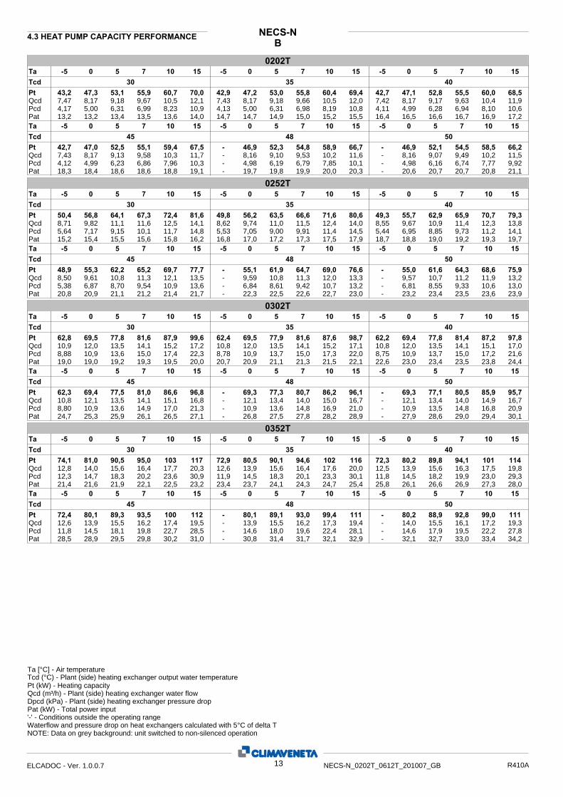
BNECS-N4.3 HEAT PUMP CAPACITY PERFORMANCE
0202T5 7 10 15 -5 0 5 7 10 15-5 0 5 7 10 15-5 0
30 35 40 43,2
13,2
7,47 4,17
Tcd Pt
Pat
Qcd Pcd
47,3 53,1 55,9 60,7 70,0 42,9 47,2 53,0 55,8 60,4 69,4 42,7 47,1 52,8 55,5 60,0 68,5
13,2 13,4 13,5 13,6 14,0 14,7 14,7 14,9 15,0 15,2 15,5 16,4 16,5 16,6 16,7 16,9 17,2
8,17 9,18 9,67 10,5 12,1 7,43 8,17 9,18 9,66 10,5 12,0 7,42 8,17 9,17 9,63 10,4 11,95,00 6,31 6,99 8,23 10,9 4,13 5,00 6,31 6,98 8,19 10,8 4,11 4,99 6,28 6,94 8,10 10,6
Ta
4,12 Pcd 4,99 6,23 6,86 7,96 10,3 - 4,98 6,19 6,79 7,85 10,1 - 4,98 6,16 6,74 7,77 9,927,43 Qcd 8,17 9,13 9,58 10,3 11,7 - 8,16 9,10 9,53 10,2 11,6 - 8,16 9,07 9,49 10,2 11,5
18,3 Pat 18,4 18,6 18,6 18,8 19,1 - 19,7 19,8 19,9 20,0 20,3 - 20,6 20,7 20,7 20,8 21,1
42,7 Pt 47,0 52,5 55,1 59,4 67,5 - 46,9 52,3 54,8 58,9 66,7 - 46,9 52,1 54,5 58,5 66,245 48 50 Tcd
15 107 5 0 -5 1510750-5 15107 5 0 -5Ta
0252T5 7 10 15 -5 0 5 7 10 15-5 0 5 7 10 15-5 0
30 35 40 50,4
15,2
8,71 5,64
Tcd Pt
Pat
Qcd Pcd
56,8 64,1 67,3 72,4 81,6 49,8 56,2 63,5 66,6 71,6 80,6 49,3 55,7 62,9 65,9 70,7 79,3
15,4 15,5 15,6 15,8 16,2 16,8 17,0 17,2 17,3 17,5 17,9 18,7 18,8 19,0 19,2 19,3 19,7
9,82 11,1 11,6 12,5 14,1 8,62 9,74 11,0 11,5 12,4 14,0 8,55 9,67 10,9 11,4 12,3 13,87,17 9,15 10,1 11,7 14,8 5,53 7,05 9,00 9,91 11,4 14,5 5,44 6,95 8,85 9,73 11,2 14,1
Ta
5,38 Pcd 6,87 8,70 9,54 10,9 13,6 - 6,84 8,61 9,42 10,7 13,2 - 6,81 8,55 9,33 10,6 13,08,50 Qcd 9,61 10,8 11,3 12,1 13,5 - 9,59 10,8 11,3 12,0 13,3 - 9,57 10,7 11,2 11,9 13,2
20,8 Pat 20,9 21,1 21,2 21,4 21,7 - 22,3 22,5 22,6 22,7 23,0 - 23,2 23,4 23,5 23,6 23,9
48,9 Pt 55,3 62,2 65,2 69,7 77,7 - 55,1 61,9 64,7 69,0 76,6 - 55,0 61,6 64,3 68,6 75,945 48 50 Tcd
15 107 5 0 -5 1510750-5 15107 5 0 -5Ta
0302T5 7 10 15 -5 0 5 7 10 15-5 0 5 7 10 15-5 0
30 35 40 62,8
19,0
10,9 8,88
Tcd Pt
Pat
Qcd Pcd
69,5 77,8 81,6 87,9 99,6 62,4 69,5 77,9 81,6 87,6 98,7 62,2 69,4 77,8 81,4 87,2 97,8
19,0 19,2 19,3 19,5 20,0 20,7 20,9 21,1 21,3 21,5 22,1 22,6 23,0 23,4 23,5 23,8 24,4
12,0 13,5 14,1 15,2 17,2 10,8 12,0 13,5 14,1 15,2 17,1 10,8 12,0 13,5 14,1 15,1 17,010,9 13,6 15,0 17,4 22,3 8,78 10,9 13,7 15,0 17,3 22,0 8,75 10,9 13,7 15,0 17,2 21,6
Ta
8,80 Pcd 10,9 13,6 14,9 17,0 21,3 - 10,9 13,6 14,8 16,9 21,0 - 10,9 13,5 14,8 16,8 20,910,8 Qcd 12,1 13,5 14,1 15,1 16,8 - 12,1 13,4 14,0 15,0 16,7 - 12,1 13,4 14,0 14,9 16,7
24,7 Pat 25,3 25,9 26,1 26,5 27,1 - 26,8 27,5 27,8 28,2 28,9 - 27,9 28,6 29,0 29,4 30,1
62,3 Pt 69,4 77,5 81,0 86,6 96,8 - 69,3 77,3 80,7 86,2 96,1 - 69,3 77,1 80,5 85,9 95,745 48 50 Tcd
15 107 5 0 -5 1510750-5 15107 5 0 -5Ta
0352T5 7 10 15 -5 0 5 7 10 15-5 0 5 7 10 15-5 0
30 35 40 74,1
21,4
12,8 12,3
Tcd Pt
Pat
Qcd Pcd
81,0 90,5 95,0 103 117 72,9 80,5 90,1 94,6 102 116 72,3 80,2 89,8 94,1 101 114
21,6 21,9 22,1 22,5 23,2 23,4 23,7 24,1 24,3 24,7 25,4 25,8 26,1 26,6 26,9 27,3 28,0
14,0 15,6 16,4 17,7 20,3 12,6 13,9 15,6 16,4 17,6 20,0 12,5 13,9 15,6 16,3 17,5 19,814,7 18,3 20,2 23,6 30,9 11,9 14,5 18,3 20,1 23,3 30,1 11,8 14,5 18,2 19,9 23,0 29,3
Ta
11,8 Pcd 14,5 18,1 19,8 22,7 28,5 - 14,6 18,0 19,6 22,4 28,1 - 14,6 17,9 19,5 22,2 27,812,6 Qcd 13,9 15,5 16,2 17,4 19,5 - 13,9 15,5 16,2 17,3 19,4 - 14,0 15,5 16,1 17,2 19,3
28,5 Pat 28,9 29,5 29,8 30,2 31,0 - 30,8 31,4 31,7 32,1 32,9 - 32,1 32,7 33,0 33,4 34,2
72,4 Pt 80,1 89,3 93,5 100 112 - 80,1 89,1 93,0 99,4 111 - 80,2 88,9 92,8 99,0 11145 48 50 Tcd
15 107 5 0 -5 1510750-5 15107 5 0 -5Ta
Ta [°C] - Air temperature Tcd (°C) - Plant (side) heating exchanger output water temperaturePt (kW) - Heating capacity
Pat (kW) - Total power input
Qcd (m³/h) - Plant (side) heating exchanger water flow Dpcd (kPa) - Plant (side) heating exchanger pressure drop
'-' - Conditions outside the operating range Waterflow and pressure drop on heat exchangers calculated with 5°C of delta TNOTE: Data on grey background: unit switched to non-silenced operation
13ELCADOC - Ver. 1.0.0.7 NECS-N_0202T_0612T_201007_GB R410A

BNECS-NHEAT PUMP CAPACITY PERFORMANCE
0412T5 7 10 15 -5 0 5 7 10 15-5 0 5 7 10 15-5 0
30 35 40 80,5
24,3
13,9 8,85
Tcd Pt
Pat
Qcd Pcd
90,3 102 108 116 132 79,5 89,7 102 107 115 130 79,5 89,6 101 106 114 129
24,7 25,2 25,4 25,9 26,7 26,5 27,0 27,6 27,9 28,3 29,2 29,2 29,8 30,4 30,7 31,2 32,0
15,6 17,7 18,6 20,1 22,9 13,8 15,5 17,6 18,5 19,9 22,6 13,8 15,5 17,5 18,4 19,8 22,311,1 14,3 15,8 18,4 23,9 8,67 11,0 14,2 15,6 18,2 23,3 8,68 11,0 14,1 15,5 17,9 22,7
Ta
8,90 Pcd 11,1 14,0 15,3 17,6 22,2 - 11,2 14,0 15,2 17,4 21,8 - 11,3 13,9 15,2 17,3 21,614,0 Qcd 15,6 17,5 18,3 19,6 22,0 - 15,7 17,5 18,3 19,5 21,9 - 15,7 17,5 18,2 19,5 21,8
32,5 Pat 33,0 33,6 33,9 34,4 35,3 - 35,2 35,8 36,0 36,5 37,4 - 36,7 37,3 37,5 38,0 38,9
80,3 Pt 89,8 101 105 113 127 - 90,1 100 105 112 126 - 90,4 100 105 112 12545 48 50 Tcd
15 107 5 0 -5 1510750-5 15107 5 0 -5Ta
0452T5 7 10 15 -5 0 5 7 10 15-5 0 5 7 10 15-5 0
30 35 40 94,7
27,2
16,4 12,2
Tcd Pt
Pat
Qcd Pcd
105 117 124 133 152 93,5 104 117 123 132 150 92,9 103 116 122 131 147
27,6 28,1 28,4 28,9 29,8 29,7 30,2 30,8 31,1 31,6 32,6 32,8 33,3 34,0 34,3 34,8 35,8
18,1 20,3 21,4 23,1 26,4 16,2 18,0 20,2 21,2 22,9 26,0 16,1 18,0 20,1 21,1 22,7 25,614,9 18,8 20,8 24,3 31,7 12,0 14,8 18,7 20,6 23,9 30,8 11,8 14,7 18,5 20,3 23,5 29,8
Ta
11,8 Pcd 14,7 18,3 20,0 23,0 28,8 - 14,7 18,2 19,9 22,7 28,2 - 14,7 18,1 19,7 22,5 27,816,1 Qcd 17,9 20,0 21,0 22,4 25,1 - 17,9 20,0 20,9 22,3 24,9 - 17,9 19,9 20,8 22,2 24,7
36,4 Pat 36,9 37,6 37,9 38,4 39,3 - 39,3 39,9 40,2 40,7 41,6 - 41,0 41,6 41,9 42,4 43,3
92,7 Pt 103 115 121 129 145 - 103 115 120 128 143 - 103 115 120 127 14245 48 50 Tcd
15 107 5 0 -5 1510750-5 15107 5 0 -5Ta
0512T5 7 10 15 -5 0 5 7 10 15-5 0 5 7 10 15-5 0
30 35 40 102
30,3
17,6 10,3
Tcd Pt
Pat
Qcd Pcd
116 132 139 150 170 102 116 131 138 149 168 102 116 131 137 147 165
30,8 31,5 31,8 32,3 33,2 33,2 33,8 34,5 34,8 35,4 36,4 36,6 37,2 38,0 38,3 38,9 39,9
20,1 22,9 24,1 26,0 29,3 17,7 20,1 22,8 23,9 25,8 29,0 17,8 20,1 22,7 23,8 25,5 28,713,3 17,3 19,1 22,2 28,4 10,3 13,3 17,1 18,9 21,9 27,8 10,4 13,3 16,9 18,6 21,5 27,1
Ta
10,5 Pcd 13,3 16,7 18,4 21,1 26,4 - 13,2 16,6 18,2 20,8 25,9 - 13,2 16,5 18,0 20,6 25,517,9 Qcd 20,1 22,5 23,6 25,3 28,3 - 20,0 22,4 23,5 25,1 28,0 - 20,0 22,4 23,4 25,0 27,8
40,5 Pat 41,2 42,0 42,3 42,8 43,9 - 43,8 44,6 44,9 45,4 46,4 - 45,6 46,4 46,7 47,2 48,1
103 Pt 115 130 136 145 163 - 115 129 135 144 161 - 115 128 134 143 16045 48 50 Tcd
15 107 5 0 -5 1510750-5 15107 5 0 -5Ta
0552T5 7 10 15 -5 0 5 7 10 15-5 0 5 7 10 15-5 0
30 35 40 121
34,4
21,0 15,4
Tcd Pt
Pat
Qcd Pcd
136 153 161 174 198 121 135 152 160 172 195 121 134 151 158 170 192
35,1 35,9 36,2 36,8 37,9 38,1 38,6 39,4 39,8 40,4 41,6 42,2 42,7 43,5 43,8 44,4 45,6
23,5 26,5 27,9 30,1 34,2 20,9 23,4 26,3 27,7 29,8 33,7 20,9 23,3 26,2 27,4 29,5 33,219,2 24,5 27,1 31,6 40,8 15,3 19,1 24,2 26,7 31,0 39,7 15,3 19,0 23,9 26,3 30,3 38,5
Ta
15,3 Pcd 18,9 23,6 25,8 29,6 37,2 - 18,8 23,4 25,5 29,2 36,4 - 18,8 23,3 25,3 28,9 35,820,9 Qcd 23,3 26,0 27,2 29,1 32,7 - 23,2 25,9 27,1 28,9 32,3 - 23,2 25,8 27,0 28,8 32,0
46,9 Pat 47,3 48,0 48,4 48,9 50,1 - 50,3 51,0 51,3 51,9 53,0 - 52,4 53,1 53,4 53,9 55,0
120 Pt 134 150 157 168 188 - 134 149 156 166 186 - 133 148 155 165 18445 48 50 Tcd
15 107 5 0 -5 1510750-5 15107 5 0 -5Ta
Ta [°C] - Air temperature Tcd (°C) - Plant (side) heating exchanger output water temperaturePt (kW) - Heating capacity
Pat (kW) - Total power input
Qcd (m³/h) - Plant (side) heating exchanger water flow Dpcd (kPa) - Plant (side) heating exchanger pressure drop
'-' - Conditions outside the operating range Waterflow and pressure drop on heat exchangers calculated with 5°C of delta TNOTE: Data on grey background: unit switched to non-silenced operation
14ELCADOC - Ver. 1.0.0.7 NECS-N_0202T_0612T_201007_GB R410A
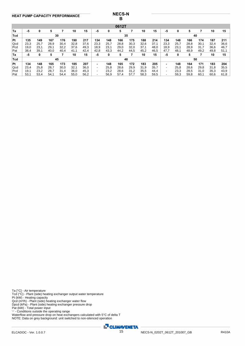
BNECS-NHEAT PUMP CAPACITY PERFORMANCE
0612T5 7 10 15 -5 0 5 7 10 15-5 0 5 7 10 15-5 0
30 35 40 135
38,4
23,3 19,0
Tcd Pt
Pat
Qcd Pcd
149 167 176 190 217 134 148 166 175 188 214 134 148 166 174 187 211
39,1 40,0 40,4 41,1 42,4 42,8 43,3 44,2 44,5 45,2 46,5 47,7 48,1 48,9 49,2 49,8 51,1
25,7 28,9 30,4 32,8 37,6 23,3 25,7 28,8 30,3 32,6 37,1 23,3 25,7 28,8 30,1 32,4 36,623,1 29,1 32,2 37,6 49,3 18,9 23,1 29,0 32,0 37,1 48,0 18,9 23,1 28,9 31,7 36,6 46,7
Ta
19,1 Pcd 23,2 28,7 31,4 36,0 45,3 - 23,2 28,6 31,2 35,5 44,4 - 23,3 28,5 31,0 35,3 43,923,4 Qcd 25,8 28,7 30,0 32,1 36,0 - 25,8 28,6 29,9 31,9 35,7 - 25,8 28,6 29,8 31,8 35,5
53,1 Pat 53,4 54,1 54,4 55,0 56,2 - 56,9 57,4 57,7 58,3 59,5 - 59,3 59,8 60,1 60,6 61,8
134 Pt 148 165 173 185 207 - 148 165 172 183 205 - 148 164 171 183 20445 48 50 Tcd
15 107 5 0 -5 1510750-5 15107 5 0 -5Ta
Ta [°C] - Air temperature Tcd (°C) - Plant (side) heating exchanger output water temperaturePt (kW) - Heating capacity
Pat (kW) - Total power input
Qcd (m³/h) - Plant (side) heating exchanger water flow Dpcd (kPa) - Plant (side) heating exchanger pressure drop
'-' - Conditions outside the operating range Waterflow and pressure drop on heat exchangers calculated with 5°C of delta TNOTE: Data on grey background: unit switched to non-silenced operation
15ELCADOC - Ver. 1.0.0.7 NECS-N_0202T_0612T_201007_GB R410A
LNNECS-NHEAT PUMP CAPACITY PERFORMANCE
0202T5 7 10 15 -5 0 5 7 10 15-5 0 5 7 10 15-5 0
30 35 40 39,6
12,5
6,85 3,51
Tcd Pt
Pat
Qcd Pcd
45,3 51,7 54,5 58,9 66,8 40,2 45,5 51,7 54,5 58,8 66,7 40,8 45,8 51,7 54,3 58,6 66,4
12,6 12,8 12,9 13,0 13,3 14,1 14,2 14,3 14,4 14,6 14,9 15,8 15,9 16,1 16,2 16,3 16,6
7,83 8,94 9,42 10,2 11,6 6,97 7,89 8,96 9,43 10,2 11,6 7,08 7,94 8,97 9,43 10,2 11,54,58 5,97 6,63 7,75 9,98 3,63 4,66 6,01 6,66 7,76 9,99 3,75 4,72 6,02 6,64 7,72 9,92
Ta
3,86 Pcd 4,76 6,00 6,60 7,63 9,76 3,93 4,79 5,97 6,56 7,56 9,63 3,97 4,80 5,95 6,52 7,50 9,527,18 Qcd 7,98 8,95 9,39 10,1 11,4 7,24 8,00 8,94 9,36 10,1 11,3 7,29 8,01 8,92 9,34 10,0 11,3
17,8 Pat 17,8 18,0 18,1 18,2 18,5 19,1 19,1 19,2 19,3 19,4 19,7 20,0 20,0 20,1 20,2 20,3 20,5
41,3 Pt 45,9 51,5 54,1 58,1 65,7 41,6 46,0 51,4 53,8 57,8 65,2 41,8 46,0 51,2 53,6 57,5 64,845 48 50 Tcd
15 107 5 0 -5 1510750-5 15107 5 0 -5Ta
0252T5 7 10 15 -5 0 5 7 10 15-5 0 5 7 10 15-5 0
30 35 40 47,7
14,6
8,25 5,07
Tcd Pt
Pat
Qcd Pcd
54,7 62,2 65,4 70,4 79,1 47,7 54,3 61,7 64,8 69,7 78,5 47,7 54,1 61,2 64,2 69,0 77,6
14,8 15,0 15,1 15,2 15,6 16,2 16,4 16,6 16,7 16,9 17,2 18,1 18,2 18,5 18,6 18,7 19,1
9,45 10,8 11,3 12,2 13,7 8,26 9,41 10,7 11,2 12,1 13,6 8,28 9,38 10,6 11,1 12,0 13,56,65 8,61 9,52 11,0 13,9 5,07 6,59 8,49 9,38 10,9 13,8 5,10 6,55 8,38 9,24 10,7 13,5
Ta
5,14 Pcd 6,52 8,27 9,09 10,5 13,1 5,17 6,52 8,21 9,00 10,3 12,9 5,20 6,52 8,17 8,94 10,2 12,78,31 Qcd 9,36 10,5 11,1 11,9 13,3 8,34 9,36 10,5 11,0 11,8 13,2 8,36 9,36 10,5 11,0 11,7 13,1
20,2 Pat 20,3 20,5 20,6 20,8 21,1 21,6 21,7 21,9 22,0 22,1 22,4 22,6 22,7 22,8 22,9 23,0 23,3
47,8 Pt 53,9 60,7 63,6 68,2 76,5 47,9 53,8 60,4 63,2 67,7 75,7 48,0 53,8 60,2 63,0 67,3 75,145 48 50 Tcd
15 107 5 0 -5 1510750-5 15107 5 0 -5Ta
0302T5 7 10 15 -5 0 5 7 10 15-5 0 5 7 10 15-5 0
30 35 40 62,4
18,7
10,8 8,77
Tcd Pt
Pat
Qcd Pcd
71,8 82,0 86,3 93,0 105 62,6 71,6 81,5 85,7 92,2 104 62,9 71,5 80,9 84,9 91,2 102
18,8 19,1 19,3 19,5 20,1 20,5 20,7 21,0 21,2 21,5 22,1 22,4 22,8 23,3 23,5 23,8 24,4
12,4 14,2 14,9 16,1 18,1 10,8 12,4 14,1 14,8 16,0 18,0 10,9 12,4 14,0 14,7 15,8 17,811,6 15,1 16,7 19,4 24,7 8,84 11,6 15,0 16,6 19,2 24,2 8,96 11,6 14,8 16,3 18,8 23,8
Ta
9,12 Pcd 11,5 14,6 16,1 18,5 23,3 9,24 11,5 14,5 15,9 18,2 23,0 9,33 11,5 14,4 15,7 18,1 22,811,0 Qcd 12,4 13,9 14,6 15,7 17,6 11,1 12,4 13,9 14,5 15,6 17,5 11,1 12,4 13,8 14,5 15,5 17,4
24,6 Pat 25,2 25,8 26,1 26,4 27,1 26,0 26,7 27,5 27,7 28,2 28,9 27,0 27,8 28,6 28,9 29,4 30,1
63,4 Pt 71,3 80,2 84,1 90,2 101 63,7 71,1 79,7 83,5 89,5 101 64,0 71,0 79,4 83,1 89,0 10045 48 50 Tcd
15 107 5 0 -5 1510750-5 15107 5 0 -5Ta
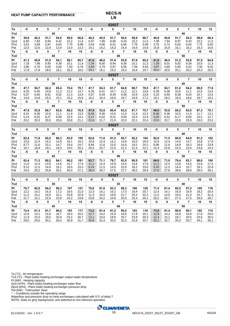
0352T5 7 10 15 -5 0 5 7 10 15-5 0 5 7 10 15-5 0
30 35 40 70,7
21,7
12,2 11,2
Tcd Pt
Pat
Qcd Pcd
82,0 94,2 99,3 107 121 70,9 81,6 93,3 98,3 106 120 71,5 81,4 92,5 97,2 105 118
22,1 22,6 22,8 23,2 23,8 23,8 24,2 24,8 25,0 25,4 26,1 26,2 26,7 27,3 27,5 28,0 28,7
14,2 16,3 17,2 18,5 21,0 12,3 14,1 16,2 17,0 18,4 20,7 12,4 14,1 16,0 16,9 18,2 20,515,1 19,9 22,1 25,8 32,9 11,3 15,0 19,6 21,7 25,2 32,2 11,5 14,9 19,3 21,3 24,7 31,4
Ta
11,9 Pcd 15,0 19,0 20,9 24,2 30,7 12,1 15,0 18,8 20,7 23,9 30,3 12,4 15,1 18,7 20,5 23,6 30,012,6 Qcd 14,1 15,9 16,7 18,0 20,2 12,7 14,2 15,9 16,6 17,8 20,1 12,8 14,2 15,8 16,6 17,8 20,0
29,0 Pat 29,5 30,1 30,4 30,9 31,7 30,8 31,4 32,0 32,3 32,8 33,7 32,1 32,7 33,3 33,7 34,1 35,1
72,4 Pt 81,3 91,7 96,2 103 117 73,2 81,4 91,2 95,5 103 116 73,8 81,4 90,9 95,1 102 11545 48 50 Tcd
15 107 5 0 -5 1510750-5 15107 5 0 -5Ta
Ta [°C] - Air temperature Tcd (°C) - Plant (side) heating exchanger output water temperaturePt (kW) - Heating capacity
Pat (kW) - Total power input
Qcd (m³/h) - Plant (side) heating exchanger water flow Dpcd (kPa) - Plant (side) heating exchanger pressure drop
'-' - Conditions outside the operating range Waterflow and pressure drop on heat exchangers calculated with 5°C of delta TNOTE: Data on grey background: unit switched to non-silenced operation
16ELCADOC - Ver. 1.0.0.7 NECS-N_0202T_0612T_201007_GB R410A
LNNECS-NHEAT PUMP CAPACITY PERFORMANCE
0412T5 7 10 15 -5 0 5 7 10 15-5 0 5 7 10 15-5 0
30 35 40 83,6
24,4
14,5 9,56
Tcd Pt
Pat
Qcd Pcd
94,5 107 113 123 140 82,7 93,5 106 112 121 137 82,4 92,8 105 110 119 134
24,9 25,5 25,7 26,2 27,0 26,6 27,2 27,8 28,1 28,6 29,5 29,4 29,9 30,6 30,9 31,4 32,4
16,3 18,6 19,6 21,2 24,2 14,3 16,2 18,4 19,4 20,9 23,7 14,3 16,1 18,2 19,1 20,6 23,312,2 15,8 17,5 20,5 26,7 9,37 12,0 15,4 17,1 20,0 25,8 9,35 11,8 15,1 16,7 19,4 24,9
Ta
9,49 Pcd 11,8 14,9 16,4 18,9 24,0 9,65 11,8 14,8 16,2 18,6 23,5 9,80 11,9 14,7 16,1 18,4 23,214,4 Qcd 16,1 18,1 18,9 20,3 22,9 14,5 16,1 18,0 18,8 20,2 22,7 14,6 16,1 17,9 18,7 20,1 22,5
32,7 Pat 33,1 33,8 34,1 34,6 35,6 34,9 35,3 35,9 36,2 36,7 37,7 36,5 36,8 37,4 37,7 38,2 39,2
82,9 Pt 92,5 104 109 117 132 83,5 92,5 103 108 116 130 84,1 92,6 103 108 115 12945 48 50 Tcd
15 107 5 0 -5 1510750-5 15107 5 0 -5Ta
0452T5 7 10 15 -5 0 5 7 10 15-5 0 5 7 10 15-5 0
30 35 40 93,9
27,2
16,2 12,0
Tcd Pt
Pat
Qcd Pcd
104 118 124 134 153 93,1 104 117 123 133 151 92,7 103 116 122 131 148
27,6 28,1 28,4 28,9 29,9 29,7 30,2 30,8 31,2 31,7 32,7 32,8 33,3 34,0 34,3 34,8 35,8
18,1 20,4 21,4 23,2 26,5 16,1 18,0 20,3 21,3 23,0 26,1 16,1 17,9 20,1 21,1 22,7 25,714,9 18,9 21,0 24,5 32,0 11,9 14,7 18,7 20,7 24,1 31,1 11,8 14,6 18,5 20,4 23,6 30,2
Ta
11,9 Pcd 14,6 18,3 20,0 23,1 29,2 12,0 14,6 18,1 19,8 22,7 28,6 12,1 14,6 18,1 19,7 22,5 28,216,1 Qcd 17,9 20,0 21,0 22,5 25,3 16,2 17,9 19,9 20,9 22,3 25,0 16,3 17,9 19,9 20,8 22,2 24,9
36,4 Pat 36,9 37,6 37,9 38,4 39,4 38,8 39,3 39,9 40,2 40,7 41,7 40,5 41,0 41,6 41,9 42,4 43,3
92,8 Pt 103 115 121 129 146 93,1 103 115 120 128 144 93,4 103 114 119 128 14345 48 50 Tcd
15 107 5 0 -5 1510750-5 15107 5 0 -5Ta
0512T5 7 10 15 -5 0 5 7 10 15-5 0 5 7 10 15-5 0
30 35 40 107
30,5
18,4 11,2
Tcd Pt
Pat
Qcd Pcd
120 135 142 154 175 106 119 134 141 152 172 106 118 133 139 150 169
31,0 31,6 31,9 32,4 33,4 33,4 33,9 34,6 35,0 35,5 36,6 36,8 37,4 38,1 38,4 39,0 40,1
20,7 23,4 24,6 26,6 30,3 18,4 20,6 23,2 24,4 26,3 29,8 18,4 20,5 23,0 24,1 26,0 29,314,1 18,1 20,0 23,4 30,3 11,2 14,0 17,8 19,6 22,8 29,4 11,1 13,8 17,5 19,2 22,2 28,4
Ta
11,1 Pcd 13,7 17,2 18,8 21,6 27,3 11,0 13,6 17,0 18,6 21,3 26,6 11,0 13,6 16,9 18,4 21,0 26,218,3 Qcd 20,4 22,8 23,9 25,6 28,8 18,3 20,3 22,7 23,7 25,4 28,4 18,3 20,3 22,6 23,6 25,2 28,2
40,7 Pat 41,3 42,0 42,4 42,9 44,0 43,3 43,9 44,6 45,0 45,5 46,5 45,1 45,7 46,5 46,8 47,3 48,2
105 Pt 117 131 137 147 166 105 117 130 136 146 163 105 117 130 136 145 16245 48 50 Tcd
15 107 5 0 -5 1510750-5 15107 5 0 -5Ta
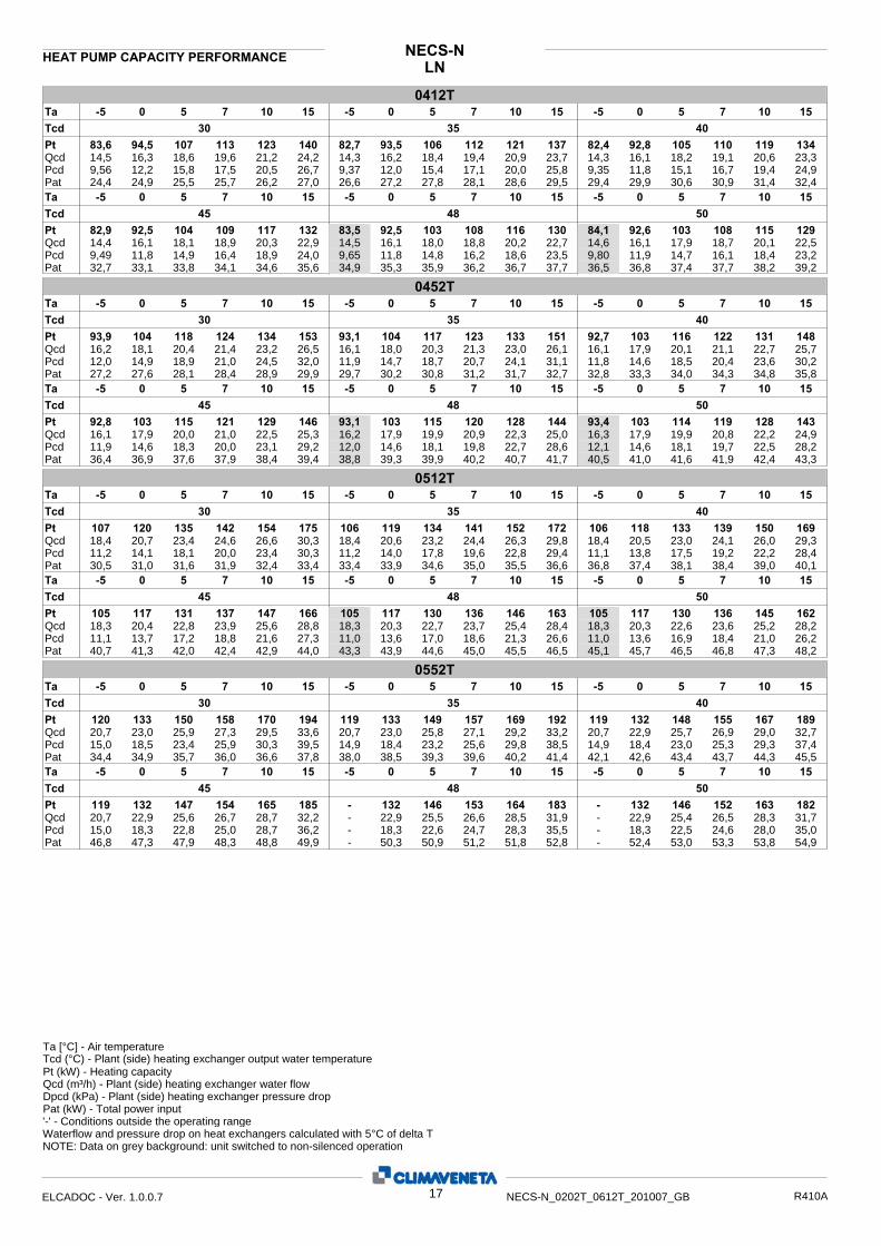
0552T5 7 10 15 -5 0 5 7 10 15-5 0 5 7 10 15-5 0
30 35 40 120
34,4
20,7 15,0
Tcd Pt
Pat
Qcd Pcd
133 150 158 170 194 119 133 149 157 169 192 119 132 148 155 167 189
34,9 35,7 36,0 36,6 37,8 38,0 38,5 39,3 39,6 40,2 41,4 42,1 42,6 43,4 43,7 44,3 45,5
23,0 25,9 27,3 29,5 33,6 20,7 23,0 25,8 27,1 29,2 33,2 20,7 22,9 25,7 26,9 29,0 32,718,5 23,4 25,9 30,3 39,5 14,9 18,4 23,2 25,6 29,8 38,5 14,9 18,4 23,0 25,3 29,3 37,4
Ta
15,0 Pcd 18,3 22,8 25,0 28,7 36,2 - 18,3 22,6 24,7 28,3 35,5 - 18,3 22,5 24,6 28,0 35,020,7 Qcd 22,9 25,6 26,7 28,7 32,2 - 22,9 25,5 26,6 28,5 31,9 - 22,9 25,4 26,5 28,3 31,7
46,8 Pat 47,3 47,9 48,3 48,8 49,9 - 50,3 50,9 51,2 51,8 52,8 - 52,4 53,0 53,3 53,8 54,9
119 Pt 132 147 154 165 185 - 132 146 153 164 183 - 132 146 152 163 18245 48 50 Tcd
15 107 5 0 -5 1510750-5 15107 5 0 -5Ta
Ta [°C] - Air temperature Tcd (°C) - Plant (side) heating exchanger output water temperaturePt (kW) - Heating capacity
Pat (kW) - Total power input
Qcd (m³/h) - Plant (side) heating exchanger water flow Dpcd (kPa) - Plant (side) heating exchanger pressure drop
'-' - Conditions outside the operating range Waterflow and pressure drop on heat exchangers calculated with 5°C of delta TNOTE: Data on grey background: unit switched to non-silenced operation
17ELCADOC - Ver. 1.0.0.7 NECS-N_0202T_0612T_201007_GB R410A

LNNECS-NHEAT PUMP CAPACITY PERFORMANCE
0612T5 7 10 15 -5 0 5 7 10 15-5 0 5 7 10 15-5 0
30 35 40 132
38,3
22,9 18,2
Tcd Pt
Pat
Qcd Pcd
146 163 172 186 213 132 146 163 171 185 210 133 146 163 170 183 207
38,9 39,8 40,2 40,9 42,1 42,7 43,2 44,0 44,4 45,0 46,3 47,7 48,0 48,7 49,1 49,7 50,9
25,2 28,3 29,7 32,1 36,8 22,9 25,2 28,2 29,6 32,0 36,4 23,0 25,3 28,2 29,5 31,8 36,022,1 27,9 30,8 36,0 47,2 18,3 22,2 27,8 30,7 35,6 46,2 18,5 22,3 27,7 30,5 35,2 45,2
Ta
18,7 Pcd 22,4 27,7 30,2 34,7 44,0 - 22,5 27,6 30,1 34,4 43,3 - 22,6 27,6 30,0 34,2 42,823,2 Qcd 25,4 28,2 29,4 31,5 35,5 - 25,4 28,1 29,4 31,4 35,2 - 25,5 28,1 29,3 31,3 35,0
53,1 Pat 53,4 53,9 54,3 54,8 56,0 - 56,8 57,3 57,6 58,2 59,3 - 59,2 59,7 60,0 60,5 61,6
133 Pt 146 162 169 181 204 - 146 162 169 180 202 - 146 161 168 180 20145 48 50 Tcd
15 107 5 0 -5 1510750-5 15107 5 0 -5Ta
Ta [°C] - Air temperature Tcd (°C) - Plant (side) heating exchanger output water temperaturePt (kW) - Heating capacity
Pat (kW) - Total power input
Qcd (m³/h) - Plant (side) heating exchanger water flow Dpcd (kPa) - Plant (side) heating exchanger pressure drop
'-' - Conditions outside the operating range Waterflow and pressure drop on heat exchangers calculated with 5°C of delta TNOTE: Data on grey background: unit switched to non-silenced operation
18ELCADOC - Ver. 1.0.0.7 NECS-N_0202T_0612T_201007_GB R410A

NECS-N5. SELECTION LIMITS
/B - 0202T ÷ 0612T
/LN - 0202T ÷ 0612T
19ELCADOC - Ver. 1.0.0.7 NECS-N_0202T_0612T_201007_GB R410A
A B
A - Operating limits in non-silent-running mode. In these conditions, ventilation is automatically increased to assu-re correct unit operation.
B - Limits with LT kit for low air temperatures

NECS-N
5.2 ETHYLENE GLYCOL MIXTURE Ethylene glycol and water mixture, used as a heat-conveying fluid, cause a variation in unit performance. For correct data, use the factors indicated in the following tabel.
0 -5 -10 -15 -20 -25 -30 -35
50%45% 40% 35%30%20%12% 0 0,960,964 0,965 0,970,9740,980,985 1 1,21,17 1,14 1,111,0751,041,02 1 1,31,27 1,24 1,221,181,111,07 1 cdp
cQ cPf
cdp: pressure drop correction factor cQ: flow correction factor cPf: cooling power correction factor For data concerning other kind of anti-freeze solutions (e,g, propylene glycol)
please contact our Sale Department.
Freezing point (°C)
Ethylene glycol percentage by weight
5.3 FOULING FACTORS Performances are based on clean condition of tubes (fouling factor = 1). For different fouling values, performance should be adjusted using the correction factors shown in the following table.
FOULING FACTORS EVAPORATOR CONDENSER/RECOVERY KE[°C]
KC [°C] FK2F2FK1F1
ff (m °CW) 2
1,000 1,000 0,0 1,000 1,000 0,0 0 1,000 1,000 0,0 1,000 1,000 0,0 1,80 x 10⁻⁵ 1,000 1,000 0,0 0,990 1,030 1,0 4,40 x 10⁻⁵ 0,960 0,990 0,7 0,980 1,040 1,5 8,80 x 10⁻⁵ 0,944 0,985 1,0 0,964 1,050 2,3 13,20 x 10⁻⁵ 0,930 0,980 1,5 0,950 1,060 3,0 17,20 x 10⁻⁵
ff: fouling factors f1 - f2: potential correction factors fk1 - fk2: compressor power input correction factors
KE: minimum condenser outlet temperature increase KC: maximum condenser outlet temperature decrease
20ELCADOC - Ver. 1.0.0.7 NECS-N_0202T_0612T_201007_GB R410A
NECS-NB/LN
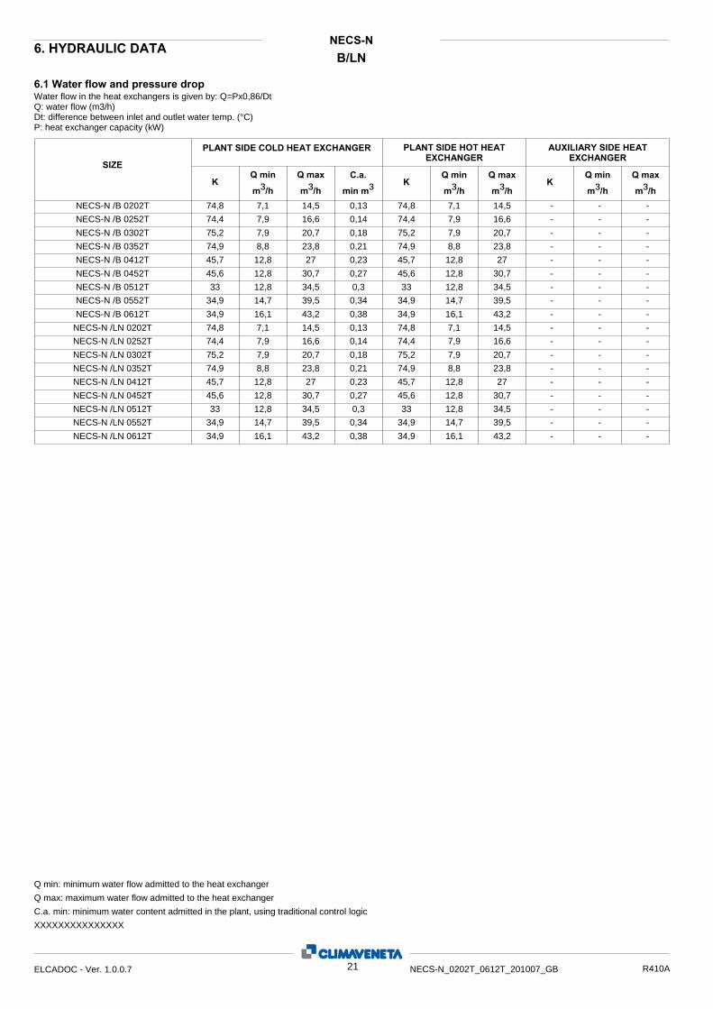
6. HYDRAULIC DATA
6.1 Water flow and pressure drop Water flow in the heat exchangers is given by: Q=Px0,86/Dt Q: water flow (m3/h) Dt: difference between inlet and outlet water temp. (°C) P: heat exchanger capacity (kW)
AUXILIARY SIDE HEAT EXCHANGER
Q max
m³/h
Q min
m³/hK
PLANT SIDE HOT HEAT EXCHANGER
Q max m³/h
Q min
m³/hK
SIZE PLANT SIDE COLD HEAT EXCHANGER
C.a.
min m³Q max
m³/h
Q min m³/h
K
74,8 7,1 14,5 0,13 74,8 7,1 14,5 - - -NECS-N /B 0202T 74,4 7,9 16,6 0,14 74,4 7,9 16,6 - - -NECS-N /B 0252T 75,2 7,9 20,7 0,18 75,2 7,9 20,7 - - -NECS-N /B 0302T 74,9 8,8 23,8 0,21 74,9 8,8 23,8 - - -NECS-N /B 0352T 45,7 12,8 27 0,23 45,7 12,8 27 - - -NECS-N /B 0412T 45,6 12,8 30,7 0,27 45,6 12,8 30,7 - - -NECS-N /B 0452T 33 12,8 34,5 0,3 33 12,8 34,5 - - -NECS-N /B 0512T
34,9 14,7 39,5 0,34 34,9 14,7 39,5 - - -NECS-N /B 0552T 34,9 16,1 43,2 0,38 34,9 16,1 43,2 - - -NECS-N /B 0612T 74,8 7,1 14,5 0,13 74,8 7,1 14,5 - - -NECS-N /LN 0202T 74,4 7,9 16,6 0,14 74,4 7,9 16,6 - - -NECS-N /LN 0252T 75,2 7,9 20,7 0,18 75,2 7,9 20,7 - - -NECS-N /LN 0302T 74,9 8,8 23,8 0,21 74,9 8,8 23,8 - - -NECS-N /LN 0352T 45,7 12,8 27 0,23 45,7 12,8 27 - - -NECS-N /LN 0412T 45,6 12,8 30,7 0,27 45,6 12,8 30,7 - - -NECS-N /LN 0452T 33 12,8 34,5 0,3 33 12,8 34,5 - - -NECS-N /LN 0512T
34,9 14,7 39,5 0,34 34,9 14,7 39,5 - - -NECS-N /LN 0552T 34,9 16,1 43,2 0,38 34,9 16,1 43,2 - - -NECS-N /LN 0612T
Q min: minimum water flow admitted to the heat exchanger Q max: maximum water flow admitted to the heat exchanger C.a. min: minimum water content admitted in the plant, using traditional control logic
XXXXXXXXXXXXXXX
21ELCADOC - Ver. 1.0.0.7 NECS-N_0202T_0612T_201007_GB R410A
The units can be supplied with a hydronic group. This houses all the main hydraulic components, thereby optimising hydrau-lic and electric installation space, time and cost. The innovative QuickMind control fitted to the units in the NECS system, has been designed to work on systems with a low water content, offering highly professional alternatives to the installation of systems featuring storage units.
Available configurations:
CENTRIFUGAL PUMPHydronic kit with one 2-pole low-head pump Hydronic kit with one 2-pole high-head pump Hydronic kit with two 2-pole low-head pumps Hydronic kit with two 2-pole high-head pumps
2-pole low head pumpCentrifugal electric pumps with hydraulic parts in AISI 304/316, insulated pump impeller and differential pressure switch on the evaporator. Pump shut-off valves fitted on both delivery and suction of a check valve for each pump installed. Hydronic kit equipped with safety valve, water pressure gauge and air vents.
2-pole high-head pump All versions of the hydronic unit can be supplied with a high-head pump. In these cases, the pump features a two-pole mo-tor even in the low noise versions.
Second pumpA second stand-by pump for high or low pressures is available on request. The pumps are automatically exchanged on the basis of a rotation programme and the stand-by pump cuts in automatically if the primary pump fails.
GENERAL CHARACTERISTICS
Water connectionsIn units without a pump, in the standard version, the water inlet and outlet connections in both the evaporator and the desuper-heater are always flush with the machine.
Water-side mechanical filter (optional)Y-filter designed and built to capture the impurities in the hy-draulic circuit. It is fitted with a 0.9 mm stainless steel mesh cartridge which can be replaced without removing the valve body from the piping.
Additional components The supply does not include the following accessories though these are recommended to ensure correct system operation:- MA Pressure gauges upline and downline from the unit - GF Flexible joints on piping - RI On-off valves- T Outlet control thermometer
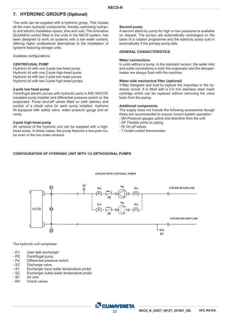
7. HYDRONIC GROUPS (Optional)
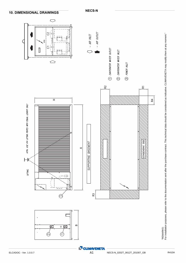
CONFIGURATION OF HYDRONIC UNIT WITH 1/2 ORTHOGONAL PUMPS
The hydronic unit comprises: - EV User side exchanger - PE Centrifugal pump - Pd Differential pressure switch - SC Discharge valve - S1 Exchanger input water temperature probe - S2 Exchanger outlet water temperature probe - SF Air vent - RH Check valves
CIRCUITS WITH 2 OPTIONAL PUMPS
SYSTEM RETURN LINE
SYSTEM DELIVERY LINE
22 NECS_N_0202T_0612T_201007_GB
NECS-N
HFC R410A
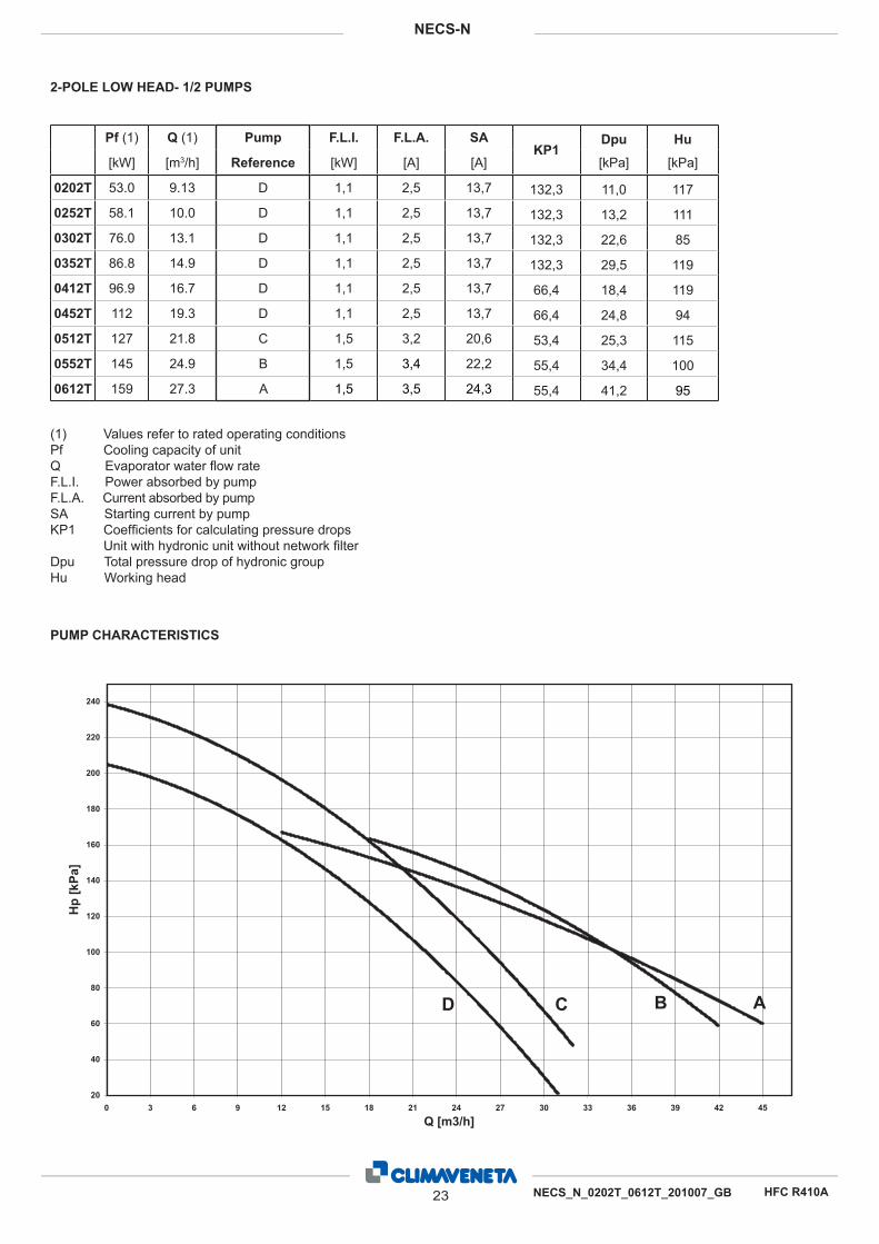
2-POLE LOW HEAD- 1/2 PUMPS
(1) Values refer to rated operating conditionsPf Cooling capacity of unitQ Evaporator water flow rate F.L.I. Power absorbed by pump F.L.A. Current absorbed by pumpSA Starting current by pump KP1 Coefficients for calculating pressure drops Unit with hydronic unit without network filterDpu Total pressure drop of hydronic groupHu Working head
PUMP CHARACTERISTICS
Pf (1) Q (1) Pump F.L.I. F.L.A. SAKP1
Dpu Hu
[kW] [m3/h] Reference [kW] [A] [A] [kPa] [kPa]
0202T 53.0 9.13 D 1,1 2,5 13,7 132,3 11,0 117
0252T 58.1 10.0 D 1,1 2,5 13,7 132,3 13,2 111
0302T 76.0 13.1 D 1,1 2,5 13,7 132,3 22,6 85
0352T 86.8 14.9 D 1,1 2,5 13,7 132,3 29,5 119
0412T 96.9 16.7 D 1,1 2,5 13,7 66,4 18,4 119
0452T 112 19.3 D 1,1 2,5 13,7 66,4 24,8 94
0512T 127 21.8 C 1,5 3,2 20,6 53,4 25,3 115
0552T 145 24.9 B 1,5 3,4 22,2 55,4 34,4 100
0612T 159 27.3 A 1,5 3,5 24,3 55,4 41,2 95
20
40
60
80
100
120
140
160
180
200
220
240
0 3 6 9 12 15 18 21 24 27 30 33 36 39 42 45
Q [m3/h]
Hp
[kPa
]
ABCD
23 NECS_N_0202T_0612T_201007_GB
NECS-N
HFC R410A
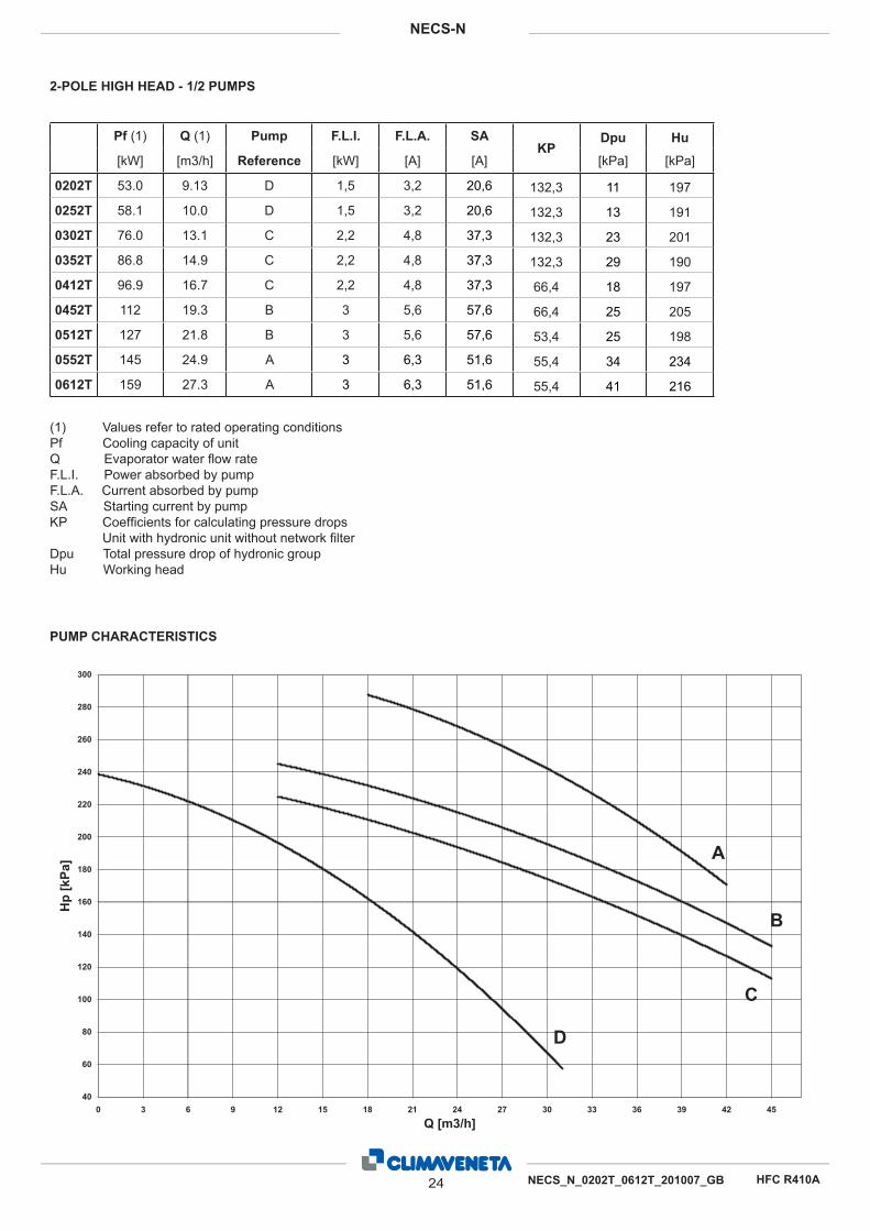
2-POLE HIGH HEAD - 1/2 PUMPS
PUMP CHARACTERISTICS
Pf (1) Q (1) Pump F.L.I. F.L.A. SAKP
Dpu Hu
[kW] [m3/h] Reference [kW] [A] [A] [kPa] [kPa]
0202T 53.0 9.13 D 1,5 3,2 20,6 132,3 11 197
0252T 58.1 10.0 D 1,5 3,2 20,6 132,3 13 191
0302T 76.0 13.1 C 2,2 4,8 37,3 132,3 23 201
0352T 86.8 14.9 C 2,2 4,8 37,3 132,3 29 190
0412T 96.9 16.7 C 2,2 4,8 37,3 66,4 18 197
0452T 112 19.3 B 3 5,6 57,6 66,4 25 205
0512T 127 21.8 B 3 5,6 57,6 53,4 25 198
0552T 145 24.9 A 3 6,3 51,6 55,4 34 234
0612T 159 27.3 A 3 6,3 51,6 55,4 41 216
(1) Values refer to rated operating conditionsPf Cooling capacity of unit Q Evaporator water flow rateF.L.I. Power absorbed by pump F.L.A. Current absorbed by pump SA Starting current by pumpKP Coefficients for calculating pressure drops Unit with hydronic unit without network filterDpu Total pressure drop of hydronic group Hu Working head
40
60
80
100
120
140
160
180
200
220
240
260
280
300
0 3 6 9 12 15 18 21 24 27 30 33 36 39 42 45
Q [m3/h]
Hp
[kPa
] A
B
C
D
24 NECS_N_0202T_0612T_201007_GB
NECS-N
HFC R410A
BNECS-N
Maximum values
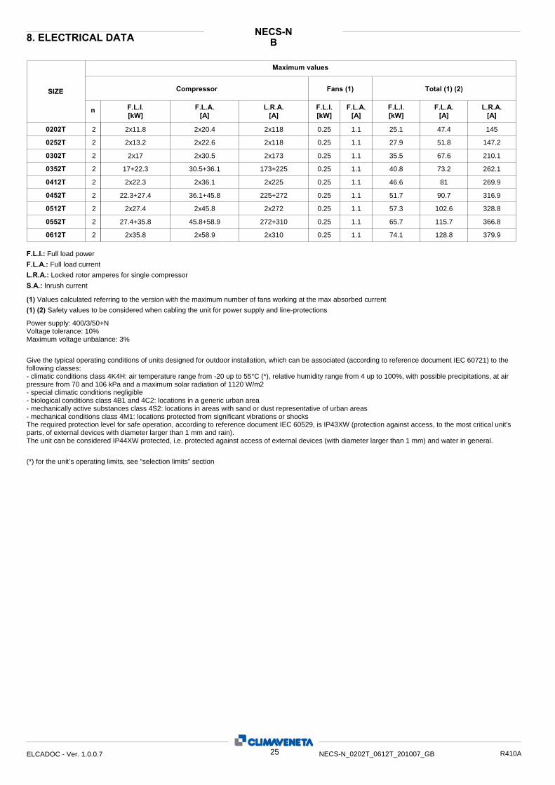
8. ELECTRICAL DATA
Compressor SIZE
n F.L.I. [kW]
F.L.A. [A]
L.R.A.[A]
L.R.A.[A]
F.L.A. [A]
F.L.I. [kW]
F.L.A.[A]
F.L.I.[kW]
Fans (1) Total (1) (2)
0202T 2 2x11.8 2x20.4 2x118 0.25 1.1 25.1 47.4 145
0252T 2 2x13.2 2x22.6 2x118 0.25 1.1 27.9 51.8 147.2
0302T 2 2x17 2x30.5 2x173 0.25 1.1 35.5 67.6 210.1
0352T 2 17+22.3 30.5+36.1 173+225 0.25 1.1 40.8 73.2 262.1
0412T 2 2x22.3 2x36.1 2x225 0.25 1.1 46.6 81 269.9
0452T 2 22.3+27.4 36.1+45.8 225+272 0.25 1.1 51.7 90.7 316.9
0512T 2 2x27.4 2x45.8 2x272 0.25 1.1 57.3 102.6 328.8
0552T 2 27.4+35.8 45.8+58.9 272+310 0.25 1.1 65.7 115.7 366.8
0612T 2 2x35.8 2x58.9 2x310 0.25 1.1 74.1 128.8 379.9
F.L.I.: Full load power F.L.A.: Full load current L.R.A.: Locked rotor amperes for single compressor S.A.: Inrush current
(1) (2) Safety values to be considered when cabling the unit for power supply and line-protections
(1) Values calculated referring to the version with the maximum number of fans working at the max absorbed current
Power supply: 400/3/50+N Voltage tolerance: 10% Maximum voltage unbalance: 3% Give the typical operating conditions of units designed for outdoor installation, which can be associated (according to reference document IEC 60721) to the following classes: - climatic conditions class 4K4H: air temperature range from -20 up to 55°C (*), relative humidity range from 4 up to 100%, with possible precipitations, at air pressure from 70 and 106 kPa and a maximum solar radiation of 1120 W/m2 - special climatic conditions negligible - biological conditions class 4B1 and 4C2: locations in a generic urban area - mechanically active substances class 4S2: locations in areas with sand or dust representative of urban areas - mechanical conditions class 4M1: locations protected from significant vibrations or shocks The required protection level for safe operation, according to reference document IEC 60529, is IP43XW (protection against access, to the most critical unit's parts, of external devices with diameter larger than 1 mm and rain). The unit can be considered IP44XW protected, i.e. protected against access of external devices (with diameter larger than 1 mm) and water in general. (*) for the unit’s operating limits, see “selection limits” section
25ELCADOC - Ver. 1.0.0.7 NECS-N_0202T_0612T_201007_GB R410A
LNNECS-N
Maximum values
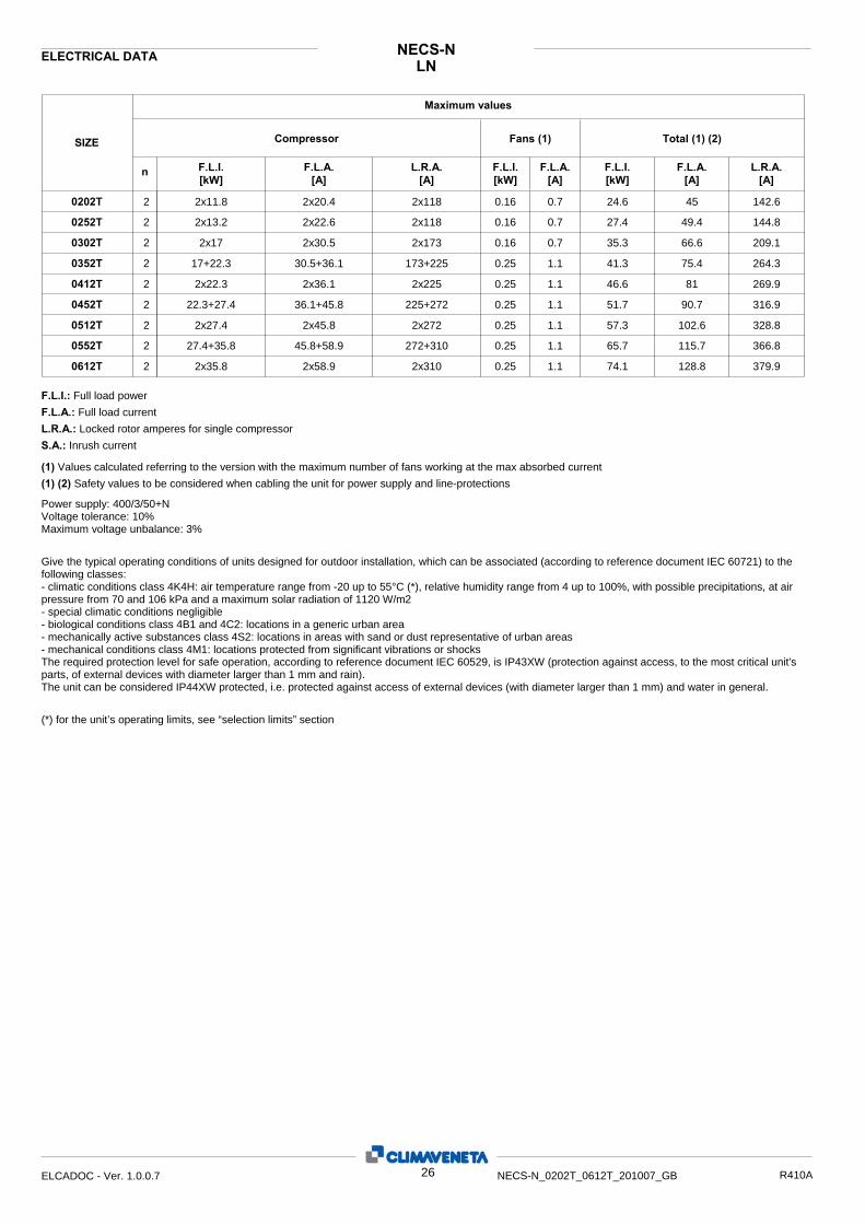
ELECTRICAL DATA
Compressor SIZE
n F.L.I. [kW]
F.L.A. [A]
L.R.A.[A]
L.R.A.[A]
F.L.A. [A]
F.L.I. [kW]
F.L.A.[A]
F.L.I.[kW]
Fans (1) Total (1) (2)
0202T 2 2x11.8 2x20.4 2x118 0.16 0.7 24.6 45 142.6
0252T 2 2x13.2 2x22.6 2x118 0.16 0.7 27.4 49.4 144.8
0302T 2 2x17 2x30.5 2x173 0.16 0.7 35.3 66.6 209.1
0352T 2 17+22.3 30.5+36.1 173+225 0.25 1.1 41.3 75.4 264.3
0412T 2 2x22.3 2x36.1 2x225 0.25 1.1 46.6 81 269.9
0452T 2 22.3+27.4 36.1+45.8 225+272 0.25 1.1 51.7 90.7 316.9
0512T 2 2x27.4 2x45.8 2x272 0.25 1.1 57.3 102.6 328.8
0552T 2 27.4+35.8 45.8+58.9 272+310 0.25 1.1 65.7 115.7 366.8
0612T 2 2x35.8 2x58.9 2x310 0.25 1.1 74.1 128.8 379.9
F.L.I.: Full load power F.L.A.: Full load current L.R.A.: Locked rotor amperes for single compressor S.A.: Inrush current
(1) (2) Safety values to be considered when cabling the unit for power supply and line-protections
(1) Values calculated referring to the version with the maximum number of fans working at the max absorbed current
Power supply: 400/3/50+N Voltage tolerance: 10% Maximum voltage unbalance: 3% Give the typical operating conditions of units designed for outdoor installation, which can be associated (according to reference document IEC 60721) to the following classes: - climatic conditions class 4K4H: air temperature range from -20 up to 55°C (*), relative humidity range from 4 up to 100%, with possible precipitations, at air pressure from 70 and 106 kPa and a maximum solar radiation of 1120 W/m2 - special climatic conditions negligible - biological conditions class 4B1 and 4C2: locations in a generic urban area - mechanically active substances class 4S2: locations in areas with sand or dust representative of urban areas - mechanical conditions class 4M1: locations protected from significant vibrations or shocks The required protection level for safe operation, according to reference document IEC 60529, is IP43XW (protection against access, to the most critical unit's parts, of external devices with diameter larger than 1 mm and rain). The unit can be considered IP44XW protected, i.e. protected against access of external devices (with diameter larger than 1 mm) and water in general. (*) for the unit’s operating limits, see “selection limits” section
26ELCADOC - Ver. 1.0.0.7 NECS-N_0202T_0612T_201007_GB R410A

BNECS-N9. FULL LOAD SOUND LEVEL
SIZE Octave band [Hz] 20001000 500 250 125 63 80004000
Total sound level
Sound power level dB(A)
SOUND POWER
84 82 86 83 79 77 70 69 850202T 84 82 86 83 79 77 70 69 850252T 84 82 86 83 79 77 70 69 850302T 85 83 87 84 80 78 71 70 860352T 85 83 87 84 80 78 71 70 860412T 85 83 87 84 80 78 71 70 860452T 86 84 88 85 81 79 72 71 870512T 86 84 88 85 81 79 72 71 870552T 86 84 88 85 81 79 72 71 870612T
Plant (side) cooling exchanger water (in/out) 12/7 °CHeat exchanger air (in) 35 °C Sound power on the basis of measurements made in compliance with ISO 9614 and Eurovent 8/1 for Eurovent certified units; in compliance with ISO 3744 for non-certified units Such certification refers specifically to the sound Power Level in dB(A). This is therefore the only acoustic data to be considered as binding.
Working conditions
SIZE Octave band [Hz] at 10 m
20001000 500 250 125 63 80004000Total sound
level Sound pressure level dB(A)
SOUND PRESSURE LEVEL
52 50 54 51 47 45 38 37 530202T 52 50 54 51 47 45 38 37 530252T 52 50 54 51 47 45 38 37 530302T 53 51 55 52 48 46 39 38 540352T 53 51 55 52 48 46 39 38 540412T 53 51 55 52 48 46 39 38 540452T 54 52 56 53 49 47 40 39 550512T 54 52 56 53 49 47 40 39 550552T 54 52 56 53 49 47 40 39 550612T
Plant (side) cooling exchanger water (in/out) 12/7 °CHeat exchanger air (in) 35 °C Average sound pressure level, at 10 (m.) distance, unit in a free field on a reflective surface; non-binding value obtained from the sound power level
Working conditions
27ELCADOC - Ver. 1.0.0.7 NECS-N_0202T_0612T_201007_GB R410A
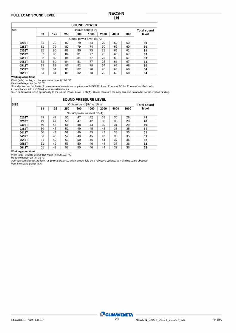
LNNECS-NFULL LOAD SOUND LEVEL
SIZE Octave band [Hz] 20001000 500 250 125 63 80004000
Total sound level
Sound power level dB(A)
SOUND POWER
81 79 82 79 74 70 62 60 800202T 81 79 82 79 74 70 62 60 800252T 82 80 83 80 75 71 63 61 810302T 82 80 84 81 77 75 68 67 830352T 82 80 84 81 77 75 68 67 830412T 82 80 84 81 77 75 68 67 830452T 83 81 85 82 78 76 69 68 840512T 83 81 85 82 78 76 69 68 840552T 83 81 85 82 78 76 69 68 840612T
Plant (side) cooling exchanger water (in/out) 12/7 °CHeat exchanger air (in) 35 °C Sound power on the basis of measurements made in compliance with ISO 9614 and Eurovent 8/1 for Eurovent certified units; in compliance with ISO 3744 for non-certified units Such certification refers specifically to the sound Power Level in dB(A). This is therefore the only acoustic data to be considered as binding.
Working conditions
SIZE Octave band [Hz] at 10 m
20001000 500 250 125 63 80004000Total sound
level Sound pressure level dB(A)
SOUND PRESSURE LEVEL
49 47 50 47 42 38 30 28 480202T 49 47 50 47 42 38 30 28 480252T 50 48 51 48 43 39 31 29 490302T 50 48 52 49 45 43 36 35 510352T 50 48 52 49 45 43 36 35 510412T 50 48 52 49 45 43 36 35 510452T 51 49 53 50 46 44 37 36 520512T 51 49 53 50 46 44 37 36 520552T 51 49 53 50 46 44 37 36 520612T
Plant (side) cooling exchanger water (in/out) 12/7 °CHeat exchanger air (in) 35 °C Average sound pressure level, at 10 (m.) distance, unit in a free field on a reflective surface; non-binding value obtained from the sound power level
Working conditions
28ELCADOC - Ver. 1.0.0.7 NECS-N_0202T_0612T_201007_GB R410A
"RE
MA
RK
S:
Fo
r in
sta
llatio
n p
urp
oses
, ple
ase
re
fer
to th
e do
cum
ent
atio
n s
ent a
fter
the
pu
rcha
se-c
ont
ract
. T
his
tech
nic
al d
ata
sh
ould
be
con
sid
ered
as
ind
icat
ive.
CLI
MA
VE
NE
TA
ma
y m
odify
the
m a
t an
y m
om
ent.
"
B
A
H
R3
R2 R1
R4
NECS-N10. DIMENSIONAL DRAWINGS
A1ELCADOC - Ver. 1.0.0.7 NECS-N_0202T_0612T_201007_GB R410A

NECS-NDIMENSIONAL DRAWINGS
ØIN/OUT
Ø IN/OUT IN/OUTR4
[mm]R3
[mm]R2
[mm]R1
[mm] WEIGHT
[kg] H
[mm] B
[mm] A
[mm]
SIZE DIMENSIONS AND WEIGHTS CLEARANCE
PLANT SIDE COLD HEAT EXCHANGER
ØTYPE TYPE TYPE
PLANT SIDE HOT HEAT EXCHANGER
AUXILIARY SIDE HEAT EXCHANGER
2195 1120 1420 645 1000 1000 600 600 GAS 2" GAS 2" - -NECS-N /B 0202T 2195 1120 1420 670 1000 1000 600 600 GAS 2" GAS 2" - -NECS-N /B 0252T 2195 1120 1420 710 1000 1000 600 600 GAS 2" GAS 2" - -NECS-N /B 0302T 2195 1120 1420 800 1000 1000 600 600 GAS 2" GAS 2" - -NECS-N /B 0352T 2745 1120 1420 985 1000 1000 600 600 GAS 2"1/2 GAS 2"1/2 - -NECS-N /B 0412T 2745 1120 1420 1030 1000 1000 600 600 GAS 2"1/2 GAS 2"1/2 - -NECS-N /B 0452T 3245 1120 1620 1175 1000 1000 600 600 GAS 2"1/2 GAS 2"1/2 - -NECS-N /B 0512T 3245 1120 1620 1220 1000 1000 600 600 GAS 2"1/2 GAS 2"1/2 - -NECS-N /B 0552T 3245 1120 1620 1265 1000 1000 600 600 GAS 2"1/2 GAS 2"1/2 - -NECS-N /B 0612T 2195 1120 1420 645 1000 1000 600 600 GAS 2" GAS 2" - -NECS-N /LN 0202T 2195 1120 1420 670 1000 1000 600 600 GAS 2" GAS 2" - -NECS-N /LN 0252T 2745 1120 1420 795 1000 1000 600 600 GAS 2" GAS 2" - -NECS-N /LN 0302T 2745 1120 1620 935 1000 1000 600 600 GAS 2" GAS 2" - -NECS-N /LN 0352T 2745 1120 1620 1060 1000 1000 600 600 GAS 2"1/2 GAS 2"1/2 - -NECS-N /LN 0412T 2745 1120 1620 1065 1000 1000 600 600 GAS 2"1/2 GAS 2"1/2 - -NECS-N /LN 0452T 3245 1120 1620 1230 1000 1000 600 600 GAS 2"1/2 GAS 2"1/2 - -NECS-N /LN 0512T 3245 1120 1620 1220 1000 1000 600 600 GAS 2"1/2 GAS 2"1/2 - -NECS-N /LN 0552T 3245 1120 1620 1265 1000 1000 600 600 GAS 2"1/2 GAS 2"1/2 - -NECS-N /LN 0612T
A2ELCADOC - Ver. 1.0.0.7 NECS-N_0202T_0612T_201007_GB R410A
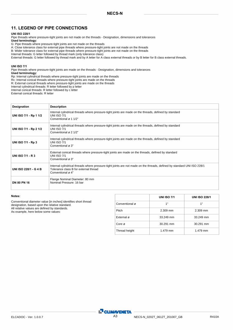
11. LEGEND OF PIPE CONNECTIONS
NECS-N
UNI ISO 228/1 Pipe threads where pressure-tight joints are not made on the threads - Designation, dimensions and tolerances Used terminology: G: Pipe threads where pressure-tight joints are not made on the threads A: Close tolerance class for external pipe threads where pressure-tight joints are not made on the threads B: Wider tolerance class for external pipe threads where pressure-tight joints are not made on the threads Internal threads: G letter followed by thread mark (only tolerance class) External threads: G letter followed by thread mark and by A letter for A class external threads or by B letter for B class external threads. UNI ISO 7/1 Pipe threads where pressure-tight joints are made on the threads - Designation, dimensions and tolerances Used terminology: Rp: Internal cylindrical threads where pressure-tight joints are made on the threads Rc: Internal conical threads where pressure-tight joints are made on the threads R: External conical threads where pressure-tight joints are made on the threads Internal cylindrical threads: R letter followed by p letter Internal conical threads: R letter followed by c letter External conical threads: R letter
UNI ISO 7/1 - Rp 1 1/2
UNI ISO 7/1 - Rp 2 1/2
UNI ISO 7/1 - Rp 3
UNI ISO 228/1 - G 4 B
DN 80 PN 16
UNI ISO 7/1 - R 3
Designation Description Internal cylindrical threads where pressure-tight joints are made on the threads, defined by standard UNI ISO 7/1 Conventional ø 1 1/2”
Internal cylindrical threads where pressure-tight joints are made on the threads, defined by standard UNI ISO 7/1 Conventional ø 2 1/2”
Internal cylindrical threads where pressure-tight joints are made on the threads, defined by standard UNI ISO 7/1 Conventional ø 3”
External conical threads where pressure-tight joints are made on the threads, defined by standard UNI ISO 7/1 Conventional ø 3”
Internal cylindrical threads where pressure-tight joints are not made on the threads, defined by standard UNI ISO 228/1Tolerance class B for external thread Conventional ø 4”
Flange Nominal Diameter: 80 mm Nominal Pressure: 16 bar
UNI ISO 7/1 UNI ISO 228/1
1"1"
2.309 mm2.309 mm
33.249 mm33.249 mm
30.291 mm30.291 mm
1.479 mm1.479 mm
Notes: Conventional diameter value [in inches] identifies short thread designation, based upon the relative standard. All relative values are defined by standards. As example, here below some values:
Conventional ø
Pitch
External ø
Core ø
Thread height
A3ELCADOC - Ver. 1.0.0.7 NECS-N_0202T_0612T_201007_GB R410A

www.climaveneta.com
Climaveneta S.p.A.Via Sarson 57/c36061 Bassano del Grappa (VI)ItalyTel +39 0424 509 500Fax +39 0424 509 [email protected]
Climaveneta France3, Village d’EntreprisesZA de la Couronne des PrésAvenue de la Mauldre78680 EpôneFranceTel +33 (0)1 30 95 19 19Fax +33 (0)1 30 95 18 [email protected]
Climaveneta DeutschlandRhenus Platz 259439 HolzwickedeGermanyTel +49 2301 91222-0Fax +49 2301 [email protected]
Climaveneta España - Top ClimaLondres 67, 1 4 08036 BarcelonaSpainTel +34 934 195 600Fax +34 934 195 [email protected]
Climaveneta Chat Union Refrig. Equipment Co Ltd88 Bai Yun Rd, Pudong XinghuoNew dev. zone 201419 ShanghaiChinaTel 008 621 575 055 66Fax 008 621 575 057 97
Climaveneta Polska Sp. z o.o.Ul. Sienkiewicza 13A,05-120 Legionowo,PolandTel +48 22 766 34 55-57Fax +48 22 784 39 [email protected]


![[hfc] [intern package]](https://img.pdfslide.us/doc/110x75/568c56a41a28ab4916c76493/hfc-intern-package.jpg)