Embed Size (px)
Citation preview
NECK INJURY PROTECTION PERFORMANCE TEST FOR REAR-END
COLLISION 1. Scope
This test procedure applies to the “Neck injury protection performance test for rear-end collision” of passenger vehicles with 9 occupants or less and commercial vehicles with a gross vehicle mass of 2.8 tons or less conducted by the National Agency for Automotive Safety and Victims’ Aid (hereinafter referred to as the “NASVA”) in the new car assessment program information supply project. Seats for the test are driver seat and front passenger seat (same row of the driver seat and outer position in the vehicle)
2. Definition of Terms
The terms used in this testing method are defined as follows: (1) “Seat” means the seats for a driver and a front passenger in the vehicle. (2) “Head Restraint” means a device designed to limit the rearward
movement of an adult occupant’s head in the event of a rear collision. (3) “Dummy” means a model simulated the human body of adult male to be
placed in the test vehicle seats. In this test, the BioRID II dummy is used. (4) “Hip Point” means the base point specified in Paragraph 4.5.1 and be measured
every test seat. (5) “Hip Point Manikin (HPM)” means a device used to determine the hip
point and actual torso angle (see SAE standard J826, 1999). (6) “Head Restraint Measuring Device (HRMD)” means a device used with
the hip point machine to measure the horizontal distance between the front surface of the head restraint and the rear of the dummy’s head and the vertical distance between the top of the head restraint and the top of the dummy’s head (see SAE paper 1999-01-0639).
(7) “Backset” means the horizontal distance between the front surface of the head restraint and the rear of the dummy’s head based on the procedure specified in Paragraph 4.5.2 using HRMD.
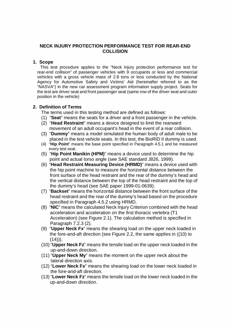
(8) “NIC” means the calculated Neck Injury Criterion combined with the head acceleration and acceleration on the first thoracic vertebra (T1 Acceleration) (see Figure 2.1). The calculation method is specified in Paragraph 7.2.3 (2).
(9) “Upper Neck Fx” means the shearing load on the upper neck loaded in the fore-and-aft direction (see Figure 2.2, the same applies in ((10) to (14))).
(10) “Upper Neck Fz” means the tensile load on the upper neck loaded in the up-and-down direction.
(11) “Upper Neck My” means the moment on the upper neck about the lateral direction axis.
(12) “Lower Neck Fx” means the shearing load on the lower neck loaded in the fore-and-aft direction.
(13) “Lower Neck Fz” means the tensile load on the lower neck loaded in the up-and-down direction.
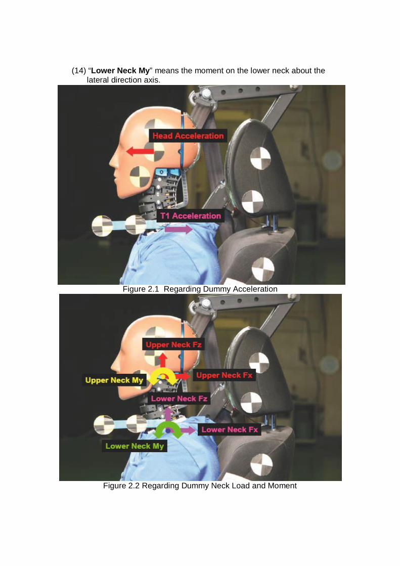
(14) “Lower Neck My” means the moment on the lower neck about the lateral direction axis.
Figure 2.1 Regarding Dummy Acceleration
Figure 2.2 Regarding Dummy Neck Load and Moment
3. Test Preparation, etc. 3.1 Selection of Test Seat
The vehicle manufacturer and importer shall submit information regarding the main structure of the driver’s seat and front passenger seat specified in Appendix 2 immediately after vehicles are selected. NASVA will review the submitted information and make a decision on the test
seat. In principle, either the driver’s seat or front passenger seat will be selected as the test seat. In the selection process, the main structure of the seat, seat back angle,
position of the hip point, and structure of the head restraint including the height and distance of the backset are examined and the identicalness of the driver’s seat and front passenger seat shall be confirmed. If both seats are identical or the driver’s seat is weaker than the front
passenger seat, the driver’s seat is selected for the test. If the front passenger seat is weaker than the driver’s seat, the front passenger seat is selected for the test. If it is difficult to select one seat, both seats are tested. If the vehicle manufacturer and importer wish the test to be conducted
additionally on a seat that has not been selected, the test institute may conduct the test using that seat.
3.2 Procurement of the Test Seat
NASVA shall consult with the vehicle manufacturer and importer for the method of procuring the test seat after the seat has been selected according to Paragraph 3.1, then procure the seat.
The manufacturer and importer shall not modify the test seat. If the test seat is difficult to procure within the time period and the delay may
affect subsequent tests, NASVA shall consult with the manufacturer and importer, then the test seat may be removed from the vehicle for the lateral collision safety performance test and the test may be conducted using this seat.
When the test seat is removed from the vehicle for the lateral collision test, it shall be after the manufacturer and importer witness marking on the body for the pedestrian head protection performance test.
After the test, in this case, NASVA shall re-install the tested seat in the test vehicle for the lateral collision test.
3.3 Submission of the Data from Vehicle Manufacturer and Importer
The vehicle manufacturer and importer shall provide NASVA with the following data necessary for preparing the test vehicle properly:
(1) Special confirmation items for test preparation (confirmation items for specific preparation of the said seat or specified series of the seat for test preparation)
(2) Appendix 1 “Information of Seat Jig (fixture) Preparation” (this information is required to the vehicle manufacturer and importer in the case, they will request NASVA to prepare the seat jig)
(3) Appendix 2 “Information of Seat Selection” (4) Appendix 3-1 “Specification of Test Seat”
(5) Appendix 4-1 “Measurement Results of Hip Point and Backset” (6) Appendix 5-1 “Dummy Positioning”
3.4 Confirmation of Identicalness of the Seats
The test institute shall check before and after the test that the test seat procured from the vehicle manufacturer and importer is identical to the test vehicle seat. The confirmation before the test is done according to Appendix 6-1 and confirmation after the test is done according to Appendix 6-2.
4. Testing Conditions
The installation condition of the seat in the vehicle shall be confirmed without occupants or goods in the vehicle, with the fuel tank filled to 100% capacity, with the spare tire and tools installed, and with the tires adjusted to the vehicle manufacturer and importer’s recommended pressure so that the vehicle is on a flat plane.
If the vehicle is equipped with a height adjustment mechanism, it shall be set at the design standard position in the stopping condition.
4.1 Seat Jig (fixture)
The seat jig, in principle, shall be supplied by the vehicle manufacturer and importer. If the vehicle manufacturer and importer cannot supply the seat jig, they shall submit information on the seat jig (Appendix 1) to NASVA. In this case, the manufacturing tolerance of the seat jig on the seat rail angle that will be produced by the test institute shall be kept within 0.2 degree in the fore-and-aft direction and lateral direction specified in the design values.
The seat jig shall not be specially treated. The test institute shall measure the main dimensions of the seat anchorage and seat jigs of the vehicle used for other assessment tests by JNCAP of the same model. If the results of comparing the main parts dimensions differ from the measurement results of the test vehicle seat, NASVA shall consult with the vehicle manufacturer and importer, then make a final decision on the requirement for main parts dimensions, etc. of the seat jig.
4.2 Seat Adjustment
The seat shall be adjusted to the positions specified in the following (1) to (11) requirements. Include combination adjustment mechanism, each mechanism of detail are shown in Attachment 1.
(1) In the case where the test seat is adjustable in the fore-and-aft direction by the seat rail, the test seat shall be adjusted to the middle position. If adjustment to the middle position is not available, the seat shall be adjusted to a position beside. If the seat has an electric adjustable mechanism in the fore-and-aft direction, the seat shall be adjusted to the middle position with a tolerance of ±2 mm.
(2) If the test seat is adjustable in the up-and-down direction (excluding the seat back angle changing automatically linked together with this adjustment), the seat shall be adjusted to the middle position. If the seat
cannot be adjusted to the middle position, the seat shall be adjusted to the nearest adjustable position lower from the middle position.
(3) If the seat back angle of the test seat is adjustable in several steps, it shall be adjusted to the design standard steps, and in the case of an electric adjuster, it shall be adjusted to the design standard angle with a tolerance of ±1°. If the seat lower installation angle is adjustable, the angle shall be adjusted to the design standard position.
(4) If the head restraint of the seat can be adjusted in the vertical direction, it shall be adjusted to the middle position. However, if the head restraint cannot be adjusted to the middle position but has a lock position within 10 mm above the middle position, it shall be used in this lock position. If the lock position is more than 10 mm above the middle position, the nearest lock position below the middle position shall be used. In this case, the adjustment range is from the lowermost position to the uppermost lock position.
(5) If the head restraint of the seat can be adjusted in the fore-and-aft direction, it shall be adjusted to the middle position. However, if the head restraint cannot be adjusted to the middle position but has a lock position within 10 mm above the middle position, it shall be used in this lock position. If the lock position is more than 10 mm above the middle position, it shall be used in the lock position rearward and nearest to the middle position. In this case, the adjustment range is from the rearmost position to the foremost lock position.
(6) If the test seat is equipped with a lumbar support device, it shall be adjusted to the rearmost position.
(7) If the test seat is equipped with a side support device, it shall be adjusted to the most spread position.
(8) If the test seat is equipped with a cushion extension device, it shall be adjusted to the rearmost position.
(9) If the test seat is equipped with an armrest, it shall be adjusted to the folded position.
(10) If the test seat has other adjustment mechanism other than (1) to (9) mentioned above, the adjustment position or the adjustment angle shall be adjusted to the design standard position or the design standard angle, respectively.
(11) If the test seat is equipped with an active head restraint, etc. which is activated by the electric signal, it shall be activated at the specified timing of the electric signal, assuming the vehicle manufacturer and importer have provided information showing that they proved the timing of the signal.
4.3 Usage of Seat Belt
A generic three-point lap-shoulder seat belt should be used during the test and the seat belt shall be belted from the left side on the dummy.
However, when the vehicle manufacturer and importer request and can demonstrate good reasons for doing so to NASVA, a vehicle-specific seat belt and geometry may be considered. The seat belt geometry and restraint equipment should then be used that approximates that of the test vehicle. The
vehicle manufacturer and importer shall provide or lend the test institute an attachment frame or fixture.
If the seat is equipped with an integrated seat belt, the vehicle’s own seat belt hardware (retractor and buckle) may be used.
4.4 Conditions for Sled and Seat Other Than above Mentioned Conditions
(1) Installation of stroboscope It shall be installed stroboscope, etc. on the sled synchronized with the
high speed photo images and electric measurements when images are photographing using high speed camera.
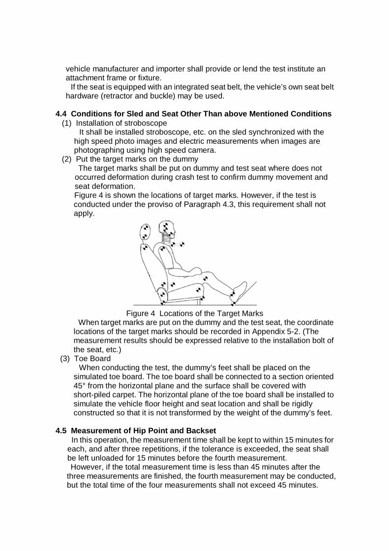
(2) Put the target marks on the dummy The target marks shall be put on dummy and test seat where does not
occurred deformation during crash test to confirm dummy movement and seat deformation. Figure 4 is shown the locations of target marks. However, if the test is conducted under the proviso of Paragraph 4.3, this requirement shall not apply.
Figure 4 Locations of the Target Marks
When target marks are put on the dummy and the test seat, the coordinate locations of the target marks should be recorded in Appendix 5-2. (The measurement results should be expressed relative to the installation bolt of the seat, etc.)
(3) Toe Board When conducting the test, the dummy’s feet shall be placed on the
simulated toe board. The toe board shall be connected to a section oriented 45° from the horizontal plane and the surface shall be covered with short-piled carpet. The horizontal plane of the toe board shall be installed to simulate the vehicle floor height and seat location and shall be rigidly constructed so that it is not transformed by the weight of the dummy’s feet.
4.5 Measurement of Hip Point and Backset
In this operation, the measurement time shall be kept to within 15 minutes for each, and after three repetitions, if the tolerance is exceeded, the seat shall be left unloaded for 15 minutes before the fourth measurement. However, if the total measurement time is less than 45 minutes after the
three measurements are finished, the fourth measurement may be conducted, but the total time of the four measurements shall not exceed 45 minutes.
4.5.1 HPM (Hip Point Manikin) Installation 4.5.1.1 The seat shall be covered by a cotton cloth large enough to cover both
the cushion and seat back. The cloth shall be tucked into the seat joint by an amount sufficient to prevent loosening of the material or fastened by adhesive tape, etc. In this case, the cotton cloth shall not be hummocky. The cotton cloth shall be as specified in “JIS D4607-1994 Three-dimensional manikins for use in defining automobile seating accommodations: kanekin 2003 or stable fiber muslin No. 9” or equivalent material.
4.5.1.2 The HPM shall be placed in the seat. 4.5.1.3 The lower legs shall be adjusted to the 50th percentile leg length setting,
and the upper legs shall be adjusted to the 10th percentile leg length setting. In addition, the ankles shall be fixed perpendicular to the shin.
4.5.1.4 The legs shall be attached to the HPM set to the 5th position (No. 5) on the knee joint T-bar, which places the knees 250 mm apart.
4.5.1.5 With the legs attached and the back pan tilted forward, a horizontal rearward load of 100 N shall be applied once to the T-bar and the HPM shall be positioned in the seat such that its mid sagittal plane coincides with the longitudinal design standard centerline of the seat.
4.5.1.6 The feet shall be placed as far forward as possible and the heels shall be on the toe board floor. The lower leg and thigh weights shall be attached to the HPM, the assembly shall be leveled to the right and left, then the lateral center of the HPM shall be adjusted to the design center of the seat.
4.5.1.7 The back pan shall be tilted forward from the seat back and the HPM assembly pushed rearward until the seat pan contacts the vehicle seat back. A horizontal rearward force of 100 N shall be applied on the push point rearward of the T-bar using a force gauge. The load application shall be repeated twice and, while keeping the 100 N applied, the back pan shall be returned to the vehicle seat back and then the load shall be released. Pay attention not to move the HPM until the following processes have been finished.
4.5.1.8 A check shall be made to determine that the HPM is level to the right and left, facing directly forward, and located in the centerline of the seat.
4.5.1.9 The right and left buttock weights shall be installed. The four chest weights shall be installed alternately on the left and right. The two large HRMD chest weights shall be attached last, flat side down.
4.5.1.10 Tilting the back pan forward to the vertical position, the assembly shall be rocked from side to side over a 10° arc (5° in each direction). This rocking shall be repeated twice while preventing movement of the seat pan of the HPM in the horizontal direction to the right and left and fore-and-aft and lifting up lightly so as not to influence the legs of the HPM. If the shape of the seat cushion prevents movement of up to 5°, it should be rocked as far as possible.
4.5.1.11 The back pan shall be returned to the seat back, the feet shall be in contact with the floor and the HPM shall be leveled to the right and left again.
4.5.1.12 After the back pan is returned to the seat, and while preventing horizontal movement of the seat pan of the HPM, the torso angle shall be stabilized to apply 10 N load in the rearward and horizontal direction to the right and left at the same height as the hanger bar.
4.5.2 Installation and Measurement of the HRMD (Head Restraint Measuring Device) 4.5.2.1 The backset probe shall be installed and pushed flush against the
HRMD. 4.5.2.2 The HRMD shall be lowered into position on the HPM torso weight
hangers and on the top edge of the channel between the hangers. 4.5.2.3 Loosening the leveling knob at the rear of the device and repositioning
the head using the HRMD water level and maintaining the HRMD level to the right and left, the leveling knob shall then be retightened by hand. If the HRMD cannot be leveled to the right and left because it contacts the head and the head rest, it shall be leveled as much as possible. If it is confirmed from documents such as drawings submitted by the vehicle manufacturer and importer for NASVA that the structure does not allow the HRMD to be level, the HRMD may be corrected to become level by calculations after NASVA has consulted the vehicle manufacturer and importer.
4.5.2.4 The HPM shall be confirmed to be level to the right and left. 4.5.2.5 Measure the height difference of the backset, head restraint and the
HRMD. 4.5.2.6 Measure both sides of the hip point location of the HPM. Both sides of the
hip location of the HPM shall be maintained within 5 mm of the X- and Z-axis. If the result is not maintained in this range, repeat the process starting from tilting the back pan forward and pushing the HPM rearward.
4.5.2.7 Measure torso angle. 4.5.2.8 Locate the screw on the center of the rear surface of the HRMD backset
probe. Mark an identifiable point on the head restraint along its vertical centerline that is defined by the first contact point between the backset probe and head restraint. The reference backset is the horizontal distance between the rearmost point on the HRMD skull and the identifiable point on the head restraint.
4.5.2.9 The measurement shall be repeated three times and it shall be confirmed for all three measurements that the difference of measured torso angle is within 1 degree, the hip point stays within 5 mm on the X- and Z-axis, and the backset stays within 5 mm.
4.5.2.10 The torso angle, hip point coordinate (X, Z), backset and height difference of the head restraint and the HRMD shall be measured three times and the average calculated after meeting the above-mentioned tolerances, then recorded in Appendix 4-2.
4.6 Installation of Dummy and Seat Belt 4.6.1 Installing the Dummy 4.6.1.1 The seat shall be left for 15 minutes before placing the dummy on it. 4.6.1.2 The dummy shall be horizontally aligned with the center of the seat, and
its upper body shall be pushed against the seat back. The torso angle of the dummy shall be adjusted to +1.5° (±2.5°), with the torso angle as described in Paragraph 4.5.2.10.
4.6.1.3 The hip point of the dummy shall be positioned at +20 mm (±5 mm) in the fore-and-aft direction and unchanged height (±5 mm) in the up-and-down direction relative to the hip point as described in Paragraph 4.5.2.10, while keeping the torso angle at +1.5°(±2.5°), and the pelvis angle as described in Paragraph 4.5.2.10. However, if the up-and-down direction of the hip point cannot be adjusted within ±5 mm, the matter shall be determined after NASVA has consulted the vehicle manufacturer and importer.
4.6.1.4 Both legs shall be adjusted such that the space between the centerlines of the knees and ankles is 200 mm (±10 mm).
4.6.1.5 By adjusting both legs of the dummy and the adjustable toe board, the top of the shoes shall be placed on the toe pan at the position of 230–270 mm from the intersection of the heel surface and the toe board by measuring alongside the toe board surface when the heels of the shoes on the dummy are placed on the heel surface.
4.6.1.6 Both arms of the dummy shall be positioned such that both of the upper arms of the dummy contact the seat back, the fifth finger of both hands contacts the upper portion of the seat cushion, and the palms of the hands face the thighs of the dummy.
4.6.1.7 The head angle shall be leveled within 0° ± 0.5°. 4.6.1.8 The amount of the dummy’s backset shall be measured. This is the
horizontal distance at the same position as the HRMD measurement. The rear of the dummy’s head shall be measured at the point which is 95 mm from the upper end of the skullcap alongside the centerline. The point marked during the backset measurement shall be used for the head restraint measurement point. A check shall be made to confirm that the dummy backset is at the standard backset +15 mm (±2 mm). If the dummy backset does not match this, the head angle, hip point coordinate, etc. shall be adjusted within the range of tolerance. Placing the highest priority on the dummy backset, the hip point X-axis coordinate, head angle and lumbar angle shall be adjusted in that order. If there is no matching even after this procedure, a decision shall be made based on consultation between NASVA and the vehicle manufacturer and importer. The measurements shall be recorded in Appendix 5-2.
4.6.2 Installing the Seat Belt
After installing the dummy in the test seat, the seat belt shall be fitted on the dummy without hindering its movement.
4.6.3 Dummy Temperature Conditions
The dummy shall be left untouched in a room in which temperature is maintained at 22.5 ± 3° for four hours or longer until immediately before testing to stabilize temperature. During this state of being left untouched, work to install the dummy, etc. may be conducted. In addition, in case of any compelling reason such as preparations to conduct testing, the dummy may not have to be left untouched in the room maintained at the applicable temperature condition for a maximum cumulative period of ten minutes. The temperature gauge shall be positioned at the height of the dummy shoulder.
4.7 Measurement of Head/Head Restraint Contact Time In order to measure the timing between the start and end of the contact of the
head and the head restraint, conductive foil (aluminum tape, etc.) shall be attached to the rear of the dummy’s head (skullcap) and the face of the head restraint for confirmation by a contact method.
5. Testing Facilities and Others 5.1 Sled
The sled shall travel along rails installed on a level and straight line, and shall create impact by acceleration or deceleration.
5.2 Illumination Device The illumination device shall be capable of emitting light sufficient for
high-speed photography and cause no halation. 5.3 High-speed Photography Device
The photographing speed of the high-speed photography device shall be set at 1,000 frames/second or faster and the shutter speed shall be set at 1/5,000 second or faster. The cameras may be equipped with polarized filters to reduce unnecessary
light.
5.4 Speed Measuring Device The test speed shall be the maximum speed of the sled. The speed shall be
calculated by integrating the sled acceleration. The sampling time (time interval of sample data) of the acceleration shall be 0.1 ms. When converting the time into the speed (km/h) of the test vehicle, the speed-measuring device shall indicate the speed to the first decimal place.
5.5 Electric Measuring Device The measuring device shall comply with the requirements of ISO 6487:2002
under the condition in which all the devices between the constituent devices and the output devices (including a computer for analytical use) are connected (measuring device under this condition is referred to as “measuring channel”.).
(1) The measurement channel shall measure acceleration, load and moment based on the channel classes listed below: (i) In the case of the collision test, channel classes be as follows:
(a) Head acceleration shall be 1,000. (b) Neck load shall be 1,000. (c) Neck moment shall be 600. (d) Fourth cervical vertebra acceleration shall be 60. (e) First thoracic vertebra acceleration shall be 60. (f) Eighth thoracic vertebra acceleration shall be 60. (g) First lumbar vertebra acceleration shall be 60. (h) Lumbar acceleration shall be 1,000. (i) Head acceleration in case of calculating NIC shall be 60.
(j) Sled acceleration shall be 60. (k) Sled acceleration in case of calculating sled speed shall be 180.
(ii) In the case of dummy verification, channel classes shall comply with the procedures specified by the dummy manufacturer, in addition to (i) above.
(2) When converting analog values into digital values in the measurement channel, the number of samples per second shall be 8,000 or more in the collision test. In the case of dummy verification, the number of samples shall be specified by the dummy manufacturer.
(3) The NIC shall be calculated with the sampling line (time interval of data samples to be conducted according to the above-described provision) set to the minimum time interval. The range of this calculation shall be between the collision and the end of contact of the rear of the dummy’s head and the head restraint after the collision.
(4) Deletion (filtering) of the high-frequency components in accordance with the channel classes shall be performed before calculating the head resultant acceleration, chest resultant acceleration, NIC, and the like.
5.6 Accelerometer, Load Meter, and Dummy 5.6.1 Accelerometer, Load Meter and Moment Meter Used in the Test
Measurement ranges of the accelerometers, load meter and moment meter used in the collision test shall be in principle within the following scopes:
(1) The measurement range of the accelerometer to be installed in the head of the dummy shall be -1,960 m/s2 (-200G) to +1,960 m/s2 (+200G).
(2) The measurement range of the load meter to be installed in the neck of the dummy shall be -5,000 N (-509 kgf) to +5,000 N (+509 kgf).
(3) The measurement range of the moment meter to be installed in the neck of the dummy shall be -200 Nm (-20.4 kgfm) to +200 Nm (+20.4 kgfm).
(4) The measurement range of the accelerometer to be installed in the vertebrae of the dummy shall be -1,960 m/s2 (-200G) to +1,960 m/s2 (+200G).
(5) The measurement range of the accelerometer to be installed in the sled shall be -490 m/s2 (-50G) to +490 m/s2 (+50G).
5.6.2 Installation of Electric Measuring Devices 5.6.2.1 Installing the Acceleration Meter
The acceleration meter shall be installed at a position in the sled without any external impact or impact from seat deformation.
5.6.2.2 Installing the Measuring Device
The measuring device shall be securely fixed in a position without any influence from seat deformation during the sled collision test. The cable connecting the transducer and the measuring device fixed in the
sled shall have sufficient margin so that it does not influence the movement on the dummy during the collision test.
5.6.3 Dummy
(1) For the dummy to be used, a BioRID II Ver.G dummy shall be used. The dummy has the following characteristics. The physical constitution is equivalent to the 50th percentile American adult male as with the Hybrid-III, with a weight of 78 kg and the vertebrae structure composed of seven cervical vertebrae, twelve thoracic vertebrae and five lumber vertebrae. For details, see “BIORID II USERS MANUAL” (29 July 2008). In order to avoid interaction with the seat belt, the cables shall come out
from the front or side of the lumbar area. (2) The attributes of each dummy section shall be probed in accordance with
the “BIORID II USERS MANUAL” (29 July 2008). The probe results shall be recorded in writing and submitted to NASVA before testing.
5.6.4 Recording Electric Measurement Results in Recording Media
Measurement results of acceleration and load shall be recorded for the channel class of 1,000 or more.
5.7 Three-dimensional Measuring Device Accuracy of the three-dimensional measuring device used to measure the
dimensions of seat position of the dummy and target mark position, etc. shall be 0.5 mm/m or less.
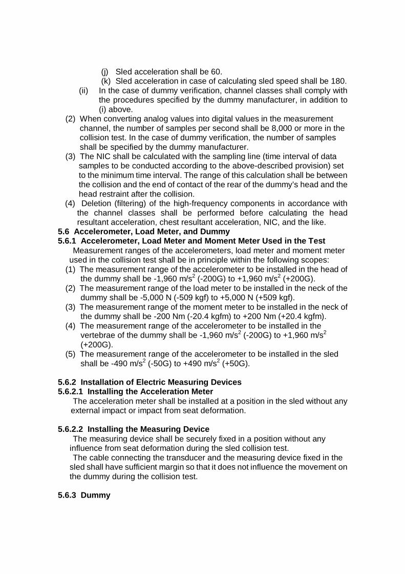
6. Testing Method 6.1 Test Speed and Impact Waveform
The maximum speed as of the end of impact generated onto the sled shall be 20.0 ±1.0 km/h. The test unit shall be so set up that the impact waveform is within the permissible range described the Diagram of Figure 6 and close to the typical impact waveform as much as possible.
20km/h Pulse
-20
0
20
40
60
80
100
120
140
0 50 100 150
Time [ms]
Acc
eler
atio
n[m
/s2 ]
Slope_UpperSlope_LowerMax_HorizontalMax_Vertical1GLevel_Upper1GLevel_Lower20km/h
Figure 6 Impact Waveform and Waveform Permissible Range
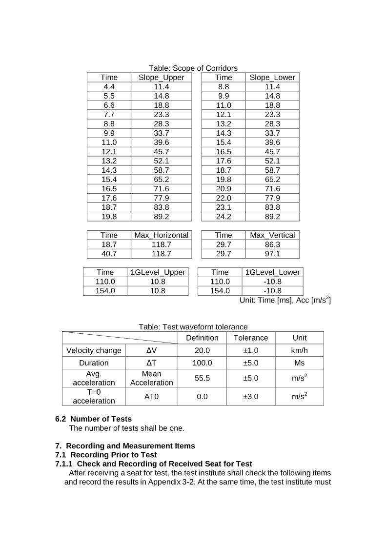
Table: Scope of Corridors Time Slope_Upper Time Slope_Lower 4.4 11.4 8.8 11.4 5.5 14.8 9.9 14.8 6.6 18.8 11.0 18.8 7.7 23.3 12.1 23.3 8.8 28.3 13.2 28.3 9.9 33.7 14.3 33.7
11.0 39.6 15.4 39.6 12.1 45.7 16.5 45.7 13.2 52.1 17.6 52.1 14.3 58.7 18.7 58.7 15.4 65.2 19.8 65.2 16.5 71.6 20.9 71.6 17.6 77.9 22.0 77.9 18.7 83.8 23.1 83.8 19.8 89.2 24.2 89.2
Time Max_Horizontal Time Max_Vertical 18.7 118.7 29.7 86.3 40.7 118.7 29.7 97.1
Time 1GLevel_Upper Time 1GLevel_Lower 110.0 10.8 110.0 -10.8 154.0 10.8 154.0 -10.8
Unit: Time [ms], Acc [m/s2]
Table: Test waveform tolerance
Definition Tolerance Unit Velocity change ΔV 20.0 ±1.0 km/h
Duration ΔT 100.0 ±5.0 Ms Avg.
acceleration Mean
Acceleration 55.5 ±5.0 m/s2
T=0 acceleration AT0 0.0 ±3.0 m/s2
6.2 Number of Tests
The number of tests shall be one. 7. Recording and Measurement Items 7.1 Recording Prior to Test 7.1.1 Check and Recording of Received Seat for Test
After receiving a seat for test, the test institute shall check the following items and record the results in Appendix 3-2. At the same time, the test institute must
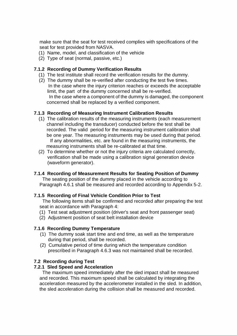
make sure that the seat for test received complies with specifications of the seat for test provided from NASVA. (1) Name, model, and classification of the vehicle (2) Type of seat (normal, passive, etc.)
7.1.2 Recording of Dummy Verification Results
(1) The test institute shall record the verification results for the dummy. (2) The dummy shall be re-verified after conducting the test five times.
In the case where the injury criterion reaches or exceeds the acceptable limit, the part of the dummy concerned shall be re-verified. In the case where a component of the dummy is damaged, the component
concerned shall be replaced by a verified component.
7.1.3 Recording of Measuring Instrument Calibration Results (1) The calibration results of the measuring instruments (each measurement
channel including the transducer) conducted before the test shall be recorded. The valid period for the measuring instrument calibration shall be one year. The measuring instruments may be used during that period.
If any abnormalities, etc. are found in the measuring instruments, the measuring instruments shall be re-calibrated at that time.
(2) To determine whether or not the injury criteria are calculated correctly, verification shall be made using a calibration signal generation device (waveform generator).
7.1.4 Recording of Measurement Results for Seating Position of Dummy
The seating position of the dummy placed in the vehicle according to Paragraph 4.6.1 shall be measured and recorded according to Appendix 5-2.
7.1.5 Recording of Final Vehicle Condition Prior to Test
The following items shall be confirmed and recorded after preparing the test seat in accordance with Paragraph 4: (1) Test seat adjustment position (driver's seat and front passenger seat) (2) Adjustment position of seat belt installation device
7.1.6 Recording Dummy Temperature
(1) The dummy soak start time and end time, as well as the temperature during that period, shall be recorded.
(2) Cumulative period of time during which the temperature condition prescribed in Paragraph 4.6.3 was not maintained shall be recorded.
7.2 Recording during Test 7.2.1 Sled Speed and Acceleration
The maximum speed immediately after the sled impact shall be measured and recorded. This maximum speed shall be calculated by integrating the acceleration measured by the accelerometer installed in the sled. In addition, the sled acceleration during the collision shall be measured and recorded.
7.2.2 Recording of Electrical Measurement Results for Dummy Sections and Sled
The electrical measurement results for the accelerometer and load meter which are installed at each of the dummy and the sled shall be recorded for a period of time from 20 ms before the collision to 300 ms or more after the collision.
(1) Sled fore-and-aft direction acceleration (2) Dummy head fore-and-aft direction acceleration (3) Dummy head lateral direction acceleration (4) Dummy head up-and-down direction acceleration (5) Dummy upper neck fore-and-aft direction load (6) Dummy upper neck lateral direction load (7) Dummy upper neck up-and-down direction load (8) Dummy upper neck fore-and-aft direction moment (9) Dummy upper neck lateral direction moment (10) Dummy upper neck up-and-down direction moment (11) Dummy lower neck fore-and-aft direction load (12) Dummy lower neck up-and-down direction load (13) Dummy lower neck lateral direction moment (14) Dummy fourth cervical vertebra fore-and-aft direction acceleration (15) Dummy fourth cervical vertebra up-and-down direction acceleration (16) Dummy first thoracic vertebra right-side fore-and-aft direction acceleration (17) Dummy first thoracic vertebra right-side up-and-down direction acceleration (18) Dummy first thoracic vertebra left-side fore-and-aft direction acceleration (19) Dummy first thoracic vertebra left-side up-and-down direction acceleration (20) Dummy eighth thoracic vertebra fore-and-aft direction acceleration (21) Dummy eighth thoracic vertebra up-and-down direction acceleration (22) Dummy first lumbar vertebra fore-and-aft direction acceleration (23) Dummy first lumbar vertebra up-and-down direction acceleration (24) Dummy lumbar area fore-and-aft direction acceleration (25) Dummy lumbar area lateral direction acceleration (26) Dummy lumbar area up-and-down direction acceleration (27) Rear of dummy head and head restraint contact signal
7.2.3 Recording of Injury Criteria
The injury criteria for the dummy shall be calculated from the waveform obtained as described in Paragraph 7.2.2 according to the following method and shall be recorded. (1) Head and head restraint contact time (T-HRCstart, T-HRCend)
The start of the head restraint contact time, T-HRCStart, shall be when the contact continues for 40 ms or longer after the rear of the dummy’s head comes in contact with the head restraint (calculated from T=0). T-HRCStart shall be rounded to the first decimal point in ms (e.g. 70.34 ms 70.3 ms).
If it is found that these figures are due to insufficient electric contact, the contact time (within 1 ms) after the second decimal point shall be tolerated. In such a case, however, it must be checked, by confirming the film, that the halt of the contact is not caused by any biomechanical phenomenon including jumping of the dummy, falling down of the head restraint/seat back, or bouncing of the head during non-structural contact with the head restraint. As a subsequent criterion, the end of the head restraint, i.e. T-HRCend, must be determined. It shall be defined as the time at which the head separates from the contact condition for the first time when the subsequent period of uninterrupted non-contact exceeds 40 ms.
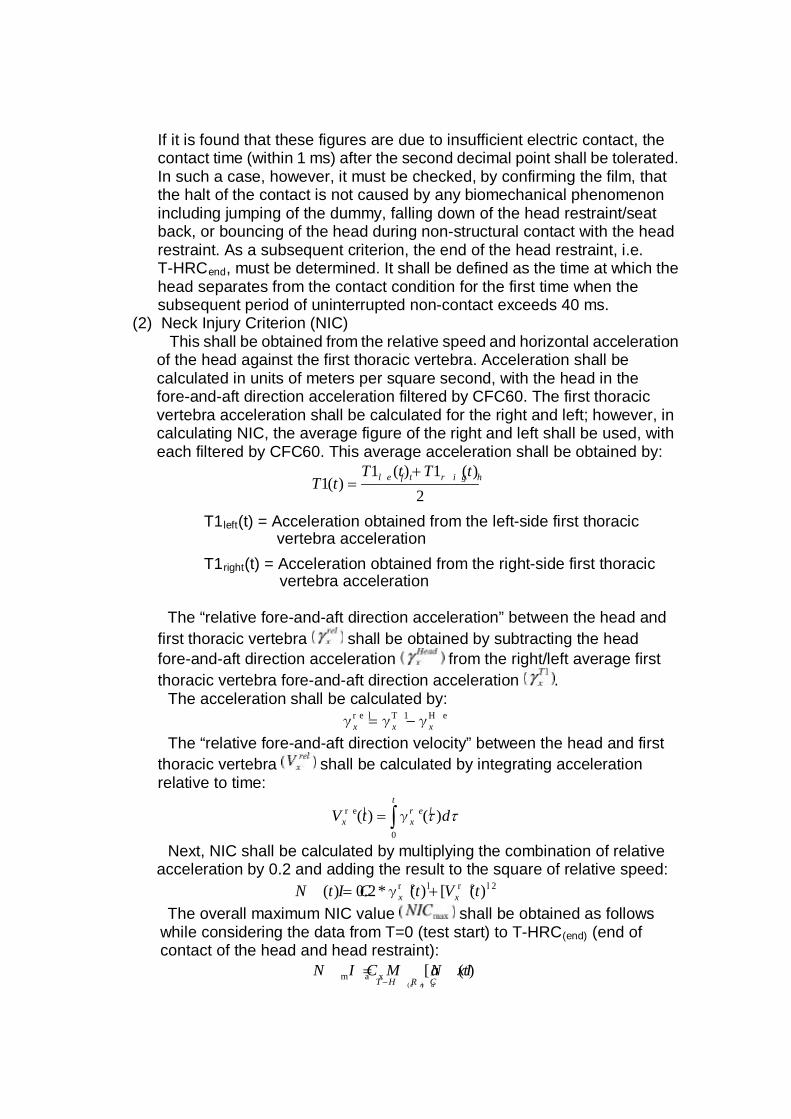
(2) Neck Injury Criterion (NIC) This shall be obtained from the relative speed and horizontal acceleration
of the head against the first thoracic vertebra. Acceleration shall be calculated in units of meters per square second, with the head in the fore-and-aft direction acceleration filtered by CFC60. The first thoracic vertebra acceleration shall be calculated for the right and left; however, in calculating NIC, the average figure of the right and left shall be used, with each filtered by CFC60. This average acceleration shall be obtained by:
2)(1)(1
)(1tTtT
tT r i g hl e f t+=
T1left(t) = Acceleration obtained from the left-side first thoracic vertebra acceleration
T1right(t) = Acceleration obtained from the right-side first thoracic vertebra acceleration
The “relative fore-and-aft direction acceleration” between the head and
first thoracic vertebra shall be obtained by subtracting the head fore-and-aft direction acceleration from the right/left average first thoracic vertebra fore-and-aft direction acceleration .
The acceleration shall be calculated by: H eT 1r e lxxx γγγ −=
The “relative fore-and-aft direction velocity” between the head and first thoracic vertebra shall be calculated by integrating acceleration relative to time:
∫=t
r e lxx dtV
0
r e l )()( ttγ
Next, NIC shall be calculated by multiplying the combination of relative
acceleration by 0.2 and adding the result to the square of relative speed: 2r e lr e l )([)(*2.0)( tVttN I C xx += γ
The overall maximum NIC value shall be obtained as follows while considering the data from T=0 (test start) to T-HRC(end) (end of contact of the head and head restraint):
)([)(
m a x tN IM a xN I Ce n dH R CT −
=
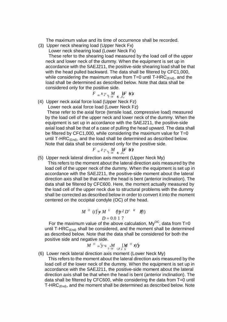
The maximum value and its time of occurrence shall be recorded. (3) Upper neck shearing load (Upper Neck Fx)
Lower neck shearing load (Lower Neck Fx) These refer to the shearing load measured by the load cell of the upper
neck and lower neck of the dummy. When the equipment is set up in accordance with the SAEJ211, the positive-side shearing load shall be that with the head pulled backward. The data shall be filtered by CFC1,000, while considering the maximum value from T=0 until T-HRC(End), and the load shall be determined as described below. Note that data shall be considered only for the positive side.
)([)(m a x tF xM a xF x
e n dH R CT −=
(4) Upper neck axial force load (Upper Neck Fz)
Lower neck axial force load (Lower Neck Fz) These refer to the axial force (tensile load, compressive load) measured
by the load cell of the upper neck and lower neck of the dummy. When the equipment is set up in accordance with the SAEJ211, the positive-side axial load shall be that of a case of pulling the head upward. The data shall be filtered by CFC1,000, while considering the maximum value for T=0 until T-HRC(End), and the load shall be determined as described below. Note that data shall be considered only for the positive side.
)([)(m a x tF zM a xF z
e n dH R CT −=
(5) Upper neck lateral direction axis moment (Upper Neck My)
This refers to the moment about the lateral direction axis measured by the load cell of the upper neck of the dummy. When the equipment is set up in accordance with the SAEJ211, the positive-side moment about the lateral direction axis shall be that when the head is bent (anterior inclination). The data shall be filtered by CFC600. Here, the moment actually measured by the load cell of the upper neck due to structural problems with the dummy shall be corrected as described below in order to convert it into the moment centered on the occipital condyle (OC) of the head.
)()()( tD FtM ytM y U pU p p e rO C −= 0 1 7 7.0=D
For the maximum value of the above calculation, MyOC, data from T=0 until T-HRC(End) shall be considered, and the moment shall be determined as described below. Note that the data shall be considered for both the positive side and negative side.
)([)(
m a x tM yM a xM y O C
H R CT
O C
e n d−=
(6) Lower neck lateral direction axis moment (Lower Neck My)
This refers to the moment about the lateral direction axis measured by the load cell of the lower neck of the dummy. When the equipment is set up in accordance with the SAEJ211, the positive-side moment about the lateral direction axis shall be that when the head is bent (anterior inclination). The data shall be filtered by CFC600, while considering the data from T=0 until T-HRC(End), and the moment shall be determined as described below. Note
that the data shall be considered for both the positive side and negative side.
)([)(m a x tM yM a xM y
e n dH R CT −=
Examples of electric measurement results measured and calculated
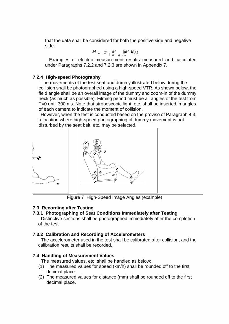
under Paragraphs 7.2.2 and 7.2.3 are shown in Appendix 7. 7.2.4 High-speed Photography
The movements of the test seat and dummy illustrated below during the collision shall be photographed using a high-speed VTR. As shown below, the field angle shall be an overall image of the dummy and zoom-in of the dummy neck (as much as possible). Filming period must be all angles of the test from T=0 until 300 ms. Note that stroboscopic light, etc. shall be inserted in angles of each camera to indicate the moment of collision. However, when the test is conducted based on the proviso of Paragraph 4.3,
a location where high-speed photographing of dummy movement is not disturbed by the seat belt, etc. may be selected.
Figure 7 High-Speed Image Angles (example)
7.3 Recording after Testing 7.3.1 Photographing of Seat Conditions Immediately after Testing
Distinctive sections shall be photographed immediately after the completion of the test.
7.3.2 Calibration and Recording of Accelerometers
The accelerometer used in the test shall be calibrated after collision, and the calibration results shall be recorded.
7.4 Handling of Measurement Values
The measured values, etc. shall be handled as below: (1) The measured values for speed (km/h) shall be rounded off to the first
decimal place. (2) The measured values for distance (mm) shall be rounded off to the first
decimal place.
(3) The measured values for angle (degree) shall be rounded off to the first decimal place.
(4) The measured values for acceleration (m/s2) shall be rounded off to the first decimal place.
(5) The measured values for load (N) shall be rounded off to the first decimal place.
(6) The measured values for moment (Nm) shall be rounded off to the first decimal place.
(7) The measured values for NIC (m2/s2) shall be rounded off to the first decimal place.
(8) The measured values for head restraint contact time (ms) shall be rounded off to the first decimal place.
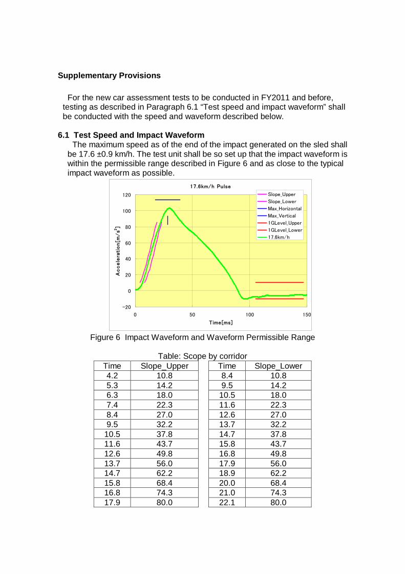
Supplementary Provisions
For the new car assessment tests to be conducted in FY2011 and before, testing as described in Paragraph 6.1 “Test speed and impact waveform” shall be conducted with the speed and waveform described below.
6.1 Test Speed and Impact Waveform
The maximum speed as of the end of the impact generated on the sled shall be 17.6 ±0.9 km/h. The test unit shall be so set up that the impact waveform is within the permissible range described in Figure 6 and as close to the typical impact waveform as possible.
17.6km/h Pulse
-20
0
20
40
60
80
100
120
0 50 100 150
Time[ms]
Accele
rati
on[m
/s2
]
Slope_Upper
Slope_Lower
Max_Horizontal
Max_Vertical
1GLevel_Upper
1GLevel_Lower
17.6km/h
Figure 6 Impact Waveform and Waveform Permissible Range
Table: Scope by corridor
Time Slope_Upper Time Slope_Lower 4.2 10.8 8.4 10.8 5.3 14.2 9.5 14.2 6.3 18.0 10.5 18.0 7.4 22.3 11.6 22.3 8.4 27.0 12.6 27.0 9.5 32.2 13.7 32.2
10.5 37.8 14.7 37.8 11.6 43.7 15.8 43.7 12.6 49.8 16.8 49.8 13.7 56.0 17.9 56.0 14.7 62.2 18.9 62.2 15.8 68.4 20.0 68.4 16.8 74.3 21.0 74.3 17.9 80.0 22.1 80.0
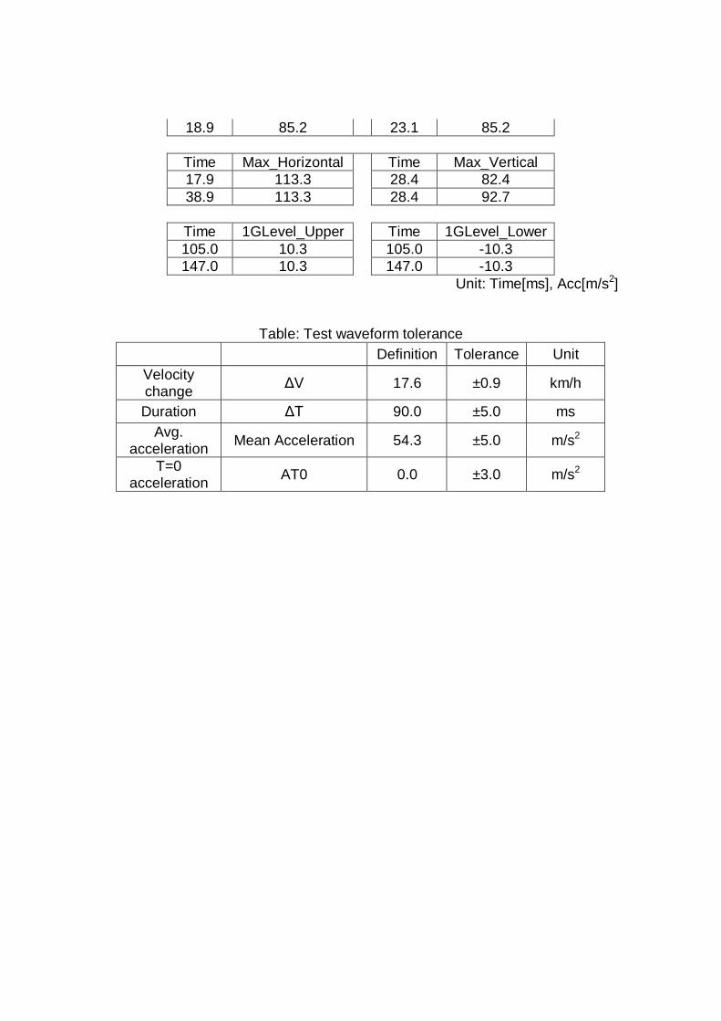
18.9 85.2 23.1 85.2
Time Max_Horizontal Time Max_Vertical 17.9 113.3 28.4 82.4 38.9 113.3 28.4 92.7
Time 1GLevel_Upper Time 1GLevel_Lower 105.0 10.3 105.0 -10.3 147.0 10.3 147.0 -10.3
Unit: Time[ms], Acc[m/s2]
Table: Test waveform tolerance Definition Tolerance Unit
Velocity change ΔV 17.6 ±0.9 km/h
Duration ΔT 90.0 ±5.0 ms Avg.
acceleration Mean Acceleration 54.3 ±5.0 m/s2
T=0 acceleration AT0 0.0 ±3.0 m/s2
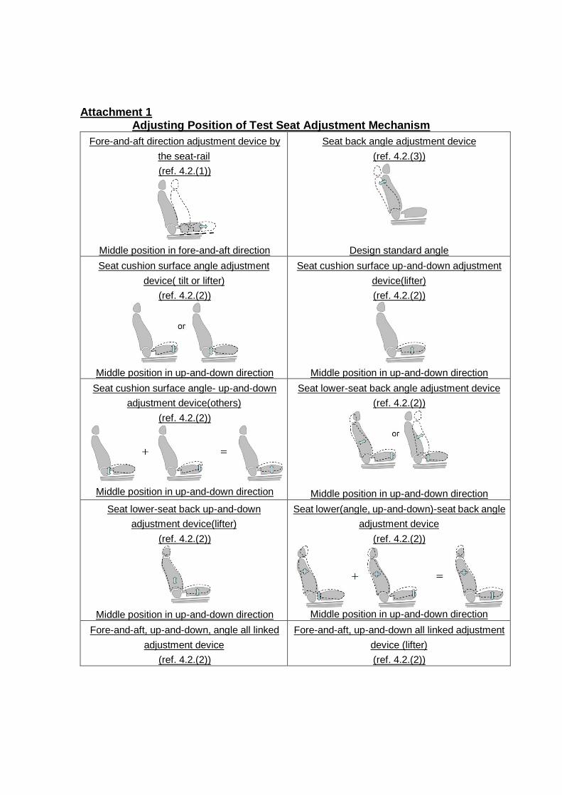
Attachment 1
Adjusting Position of Test Seat Adjustment Mechanism Fore-and-aft direction adjustment device by
the seat-rail (ref. 4.2.(1))
Middle position in fore-and-aft direction
Seat back angle adjustment device (ref. 4.2.(3))
Design standard angle Seat cushion surface angle adjustment
device( tilt or lifter) (ref. 4.2.(2))
Middle position in up-and-down direction
Seat cushion surface up-and-down adjustment device(lifter) (ref. 4.2.(2))
Middle position in up-and-down direction
Seat cushion surface angle- up-and-down adjustment device(others)
(ref. 4.2.(2))
Middle position in up-and-down direction
Seat lower-seat back angle adjustment device (ref. 4.2.(2))
Middle position in up-and-down direction Seat lower-seat back up-and-down
adjustment device(lifter) (ref. 4.2.(2))
Middle position in up-and-down direction
Seat lower(angle, up-and-down)-seat back angle adjustment device
(ref. 4.2.(2))
Middle position in up-and-down direction
Fore-and-aft, up-and-down, angle all linked adjustment device
(ref. 4.2.(2))
Fore-and-aft, up-and-down all linked adjustment device (lifter) (ref. 4.2.(2))
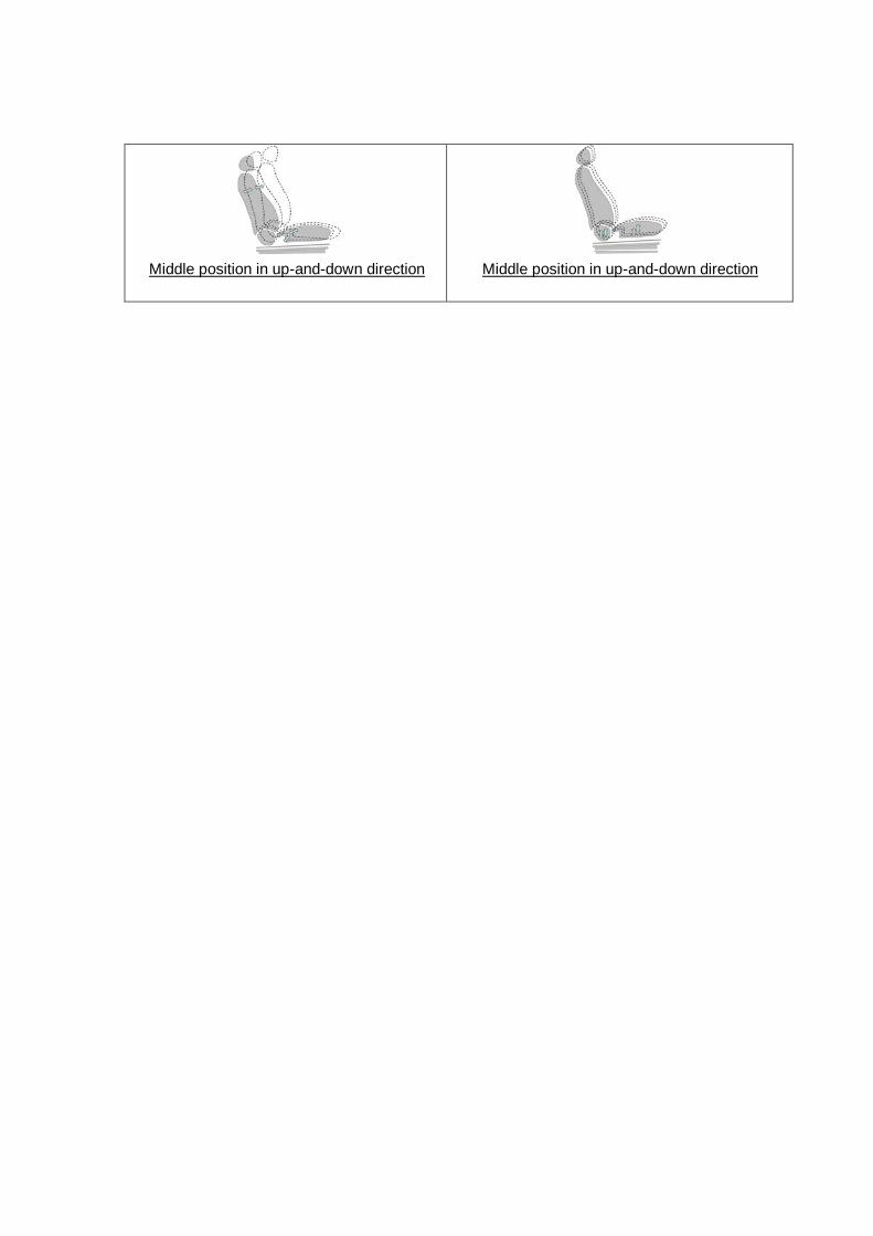
Middle position in up-and-down direction
Middle position in up-and-down direction
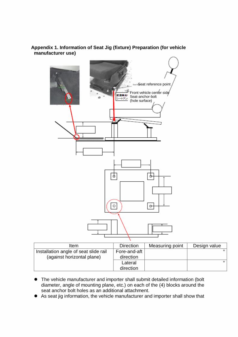
Appendix 1. Information of Seat Jig (fixture) Preparation (for vehicle
manufacturer use)
Item Direction Measuring point Design value
Installation angle of seat slide rail (against horizontal plane)
Fore-and-aft direction
°
Lateral direction
°
The vehicle manufacturer and importer shall submit detailed information (bolt
diameter, angle of mounting plane, etc.) on each of the (4) blocks around the seat anchor bolt holes as an additional attachment.
As seat jig information, the vehicle manufacturer and importer shall show that
Front vehicle center side Seat-anchor-bolt (hole surface)
Seat reference point

the relative position of the front seat anchor bolt center on the hole surface on the vehicle center side and heel height of the dummy is the same as it would be in its vehicle.
The above seat jig information is only one example; the vehicle manufacturer and importer are expected to submit all necessary information to enable the seat jig to be made properly.
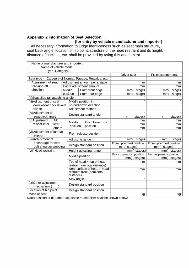
Appendix 2 Information of Seat Selection
(for entry by vehicle manufacturer and importer) All necessary information to judge identicalness such as seat main structure,
seat back angle, location of hip point, structure of the head restraint and its height, distance of backset, etc. shall be provided by using this attachment.
Name of manufacturer and importer,
Name of vehicle model
Type, Category Driver seat Fr. passenger seat
Seat type Category of Normal, Passive, Reactive, etc. (i)Adjustment of seat
fore-and-aft direction
Adjustment amount per a stage mm mm Entire adjustment amount mm mm Middle position
From front edge mm( stage) mm( stage) From rear edge mm( stage) mm( stage)
(ii)Seat slide rail attaching angle ° ° (iii)Adjustment of seat
lower –seat back linked device
Middle position in up-and-down direction
° °
Adjustment method (iv)Adjustment of
seat-back angle Design standard angle ° ( stages)
° ( stages)
(v)Adjustment of seat-lifter
Tilt Middle position
From lowermost position
mm mm lifter mm mm others mm mm
(vi)Adjustment of lumbar support From release position
(vii)Adjustment of anchorage for seat belt shoulder webbing
Adjusting range mm( stage) mm( stage)
Design standard position From uppermost position mm( stages)
From uppermost position mm( stages)
(viii)Head restraint Height adjusting range mm( stages) mm( stages)
Middle position From uppermost position mm( stages)
From uppermost position mm( stages)
Top of head ~ top of head restraint (vertical distance)
mm mm
Rear surface of head ~ head restraint front (horizontal distance)
mm mm
Stay angle ° ° (ix)Other adjustment
mechanism ( ) Design standard position
Location of hip point Design standard position Mass of seat kg kg
Note) position of (ix) other adjustable mechanism shall be shown below:
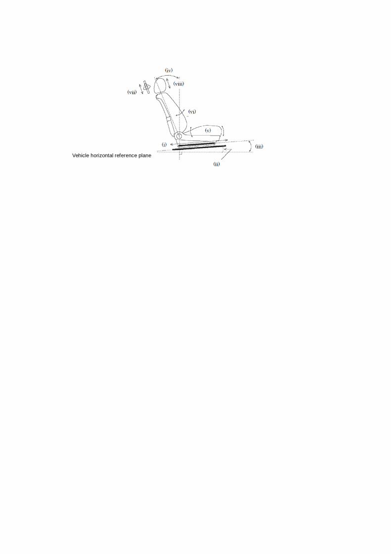
Vehicle horizontal reference plane
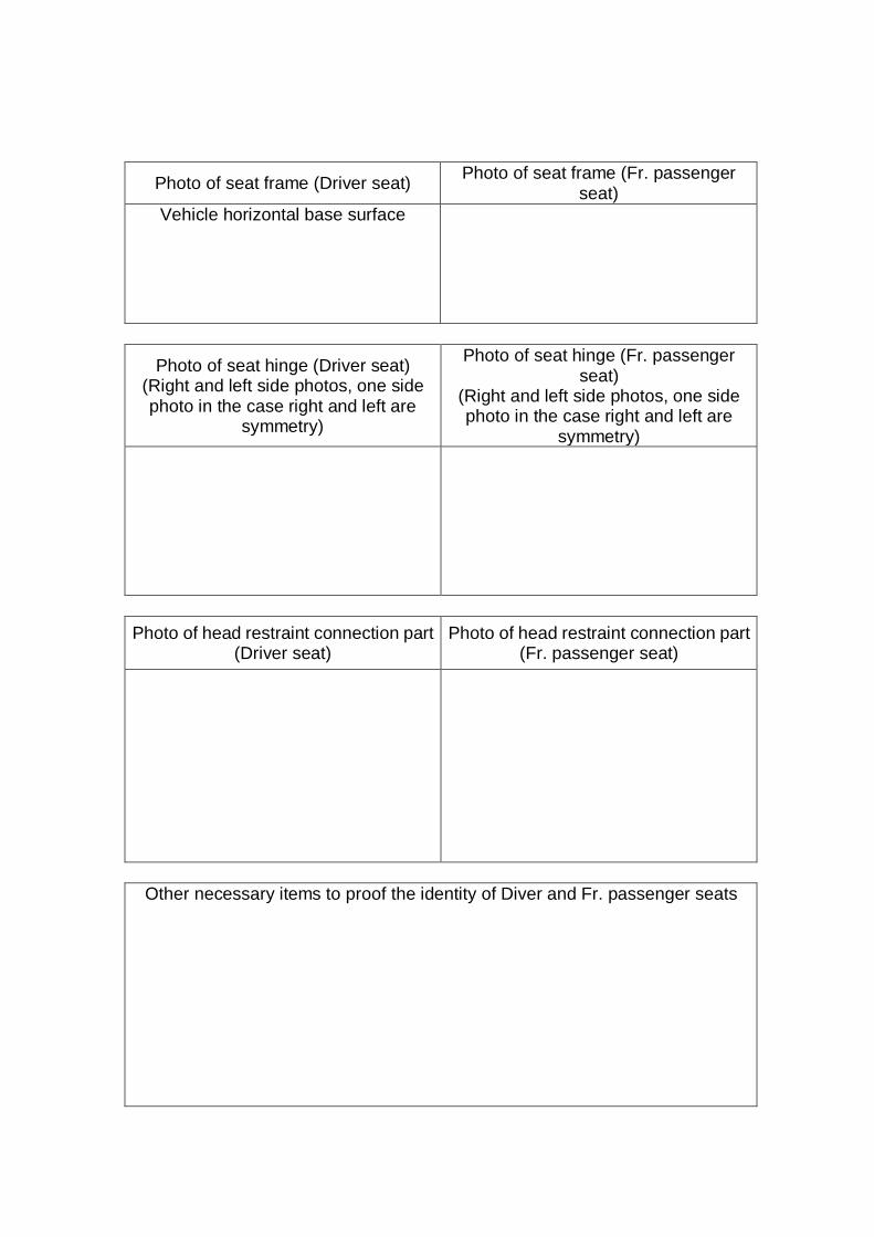
Photo of seat frame (Driver seat) Photo of seat frame (Fr. passenger seat)
Vehicle horizontal base surface
Photo of seat hinge (Driver seat) (Right and left side photos, one side photo in the case right and left are
symmetry)
Photo of seat hinge (Fr. passenger seat)
(Right and left side photos, one side photo in the case right and left are
symmetry)
Photo of head restraint connection part
(Driver seat) Photo of head restraint connection part
(Fr. passenger seat)
Other necessary items to proof the identity of Diver and Fr. passenger seats
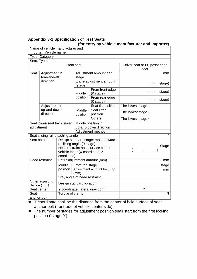
Appendix 3-1 Specification of Test Seats
(for entry by vehicle manufacturer and importer) Name of vehicle manufacturer and importer, Vehicle name
Type, Category Seat, Type
Front seat Driver seat or Fr. passenger seat
Seat Adjustment in fore-and-aft direction
Adjustment amount per stage
mm
Entire adjustment amount (stage) mm ( stage)
Middle position
From front edge (0 stage) mm ( stage)
From rear edge (0 stage) mm ( stage)
Adjustment in up-and-down direction
Middle position
Seat tilt position The lowest stage ~ Seat lifter position The lowest stage ~
Others The lowest stage ~ Seat lower-seat back linked adjustment
Middle position in up-and-down direction
°
Adjustment method Seat sliding rail attaching angle ° Seat back Design standard stage: most forward
reclining angle (0 stage) Head restraint hole surface center vehicle inner (X coordinate, Z coordinate)
Stage ( , )
Head restraint Entire adjustment amount (mm) mm Middle position
From top stage stage Adjustment amount from top (mm)
mm
Stay angle of head restraint Other adjusting device ( ) Design standard location
Seat center Y coordinate (lateral direction) Y= Seat anchor-bolt
Torque of clamp N
Y coordinate shall be the distance from the center of hole surface of seat anchor bolt (front side of vehicle center side)
The number of stages for adjustment position shall start from the first locking position (“stage 0”)
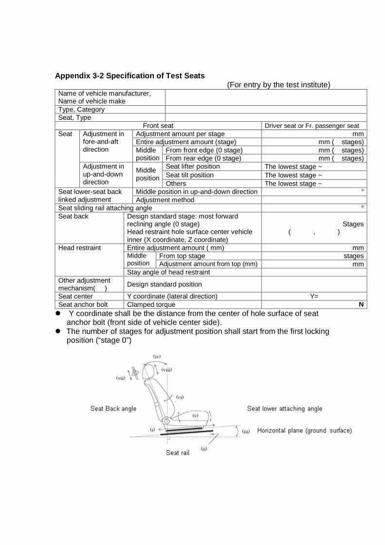
Appendix 3-2 Specification of Test Seats
(For entry by the test institute) Name of vehicle manufacturer, Name of vehicle make
Type, Category Seat, Type
Front seat Driver seat or Fr. passenger seat Seat Adjustment in
fore-and-aft direction
Adjustment amount per stage mm Entire adjustment amount (stage) mm ( stages) Middle position
From front edge (0 stage) mm ( stages) From rear edge (0 stage) mm ( stages)
Adjustment in up-and-down direction
Middle position
Seat lifter position The lowest stage ~ Seat tilt position The lowest stage ~ Others The lowest stage ~
Seat lower-seat back linked adjustment
Middle position in up-and-down direction ° Adjustment method
Seat sliding rail attaching angle ° Seat back Design standard stage: most forward
reclining angle (0 stage) Head restraint hole surface center vehicle inner (X coordinate, Z coordinate)
Stages ( , )
Head restraint Entire adjustment amount ( mm) mm Middle position
From top stage stages Adjustment amount from top (mm) mm
Stay angle of head restraint Other adjustment mechanism( ) Design standard position
Seat center Y coordinate (lateral direction) Y= Seat anchor bolt Clamped torque N Y coordinate shall be the distance from the center of hole surface of seat
anchor bolt (front side of vehicle center side). The number of stages for adjustment position shall start from the first locking
position (“stage 0”)
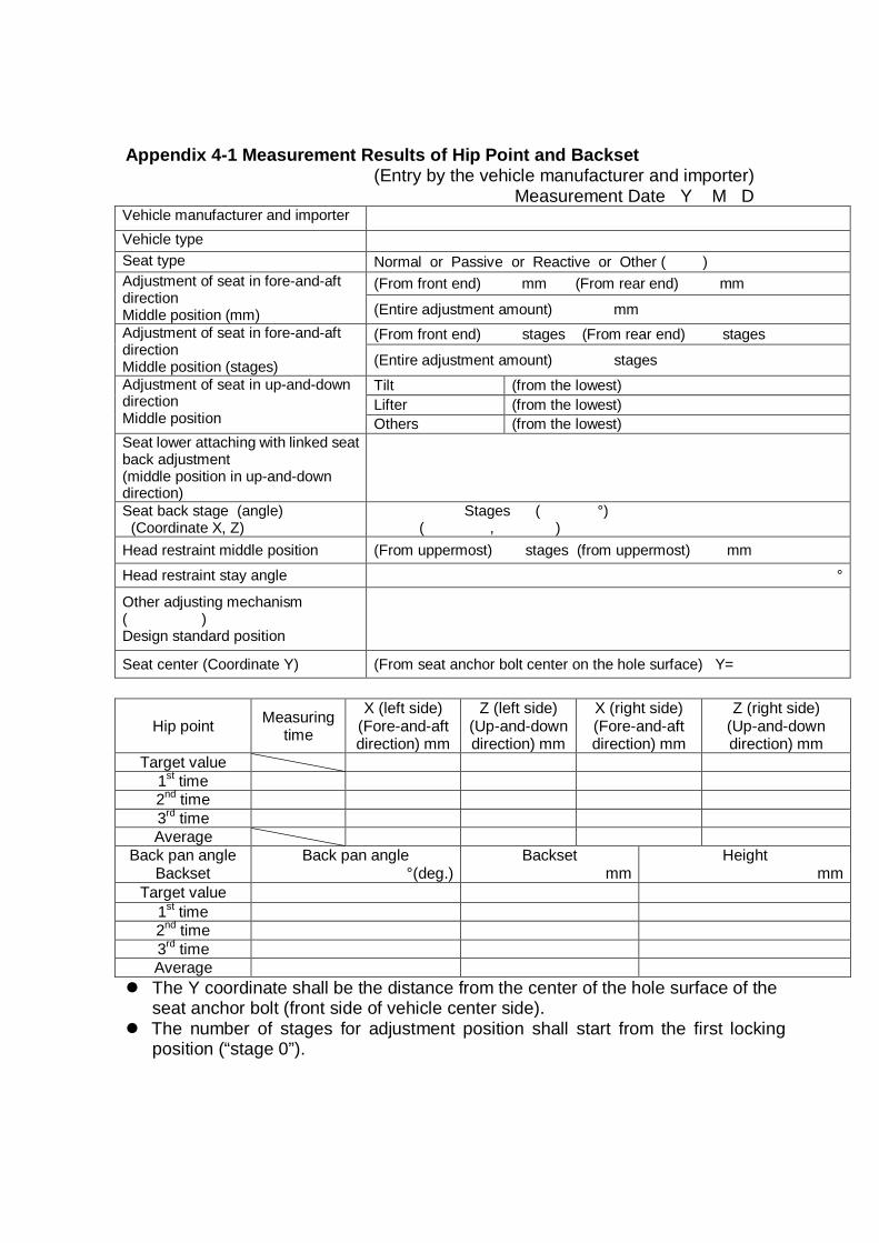
Appendix 4-1 Measurement Results of Hip Point and Backset (Entry by the vehicle manufacturer and importer)
Measurement Date Y M D Vehicle manufacturer and importer Vehicle type Seat type Normal or Passive or Reactive or Other ( ) Adjustment of seat in fore-and-aft direction Middle position (mm)
(From front end) mm (From rear end) mm
(Entire adjustment amount) mm Adjustment of seat in fore-and-aft direction Middle position (stages)
(From front end) stages (From rear end) stages
(Entire adjustment amount) stages Adjustment of seat in up-and-down direction Middle position
Tilt (from the lowest) Lifter (from the lowest) Others (from the lowest)
Seat lower attaching with linked seat back adjustment (middle position in up-and-down direction)
Seat back stage (angle) (Coordinate X, Z)
Stages ( °) ( , )
Head restraint middle position (From uppermost) stages (from uppermost) mm
Head restraint stay angle °
Other adjusting mechanism ( ) Design standard position
Seat center (Coordinate Y) (From seat anchor bolt center on the hole surface) Y=
Hip point Measuring time
X (left side) (Fore-and-aft direction) mm
Z (left side) (Up-and-down direction) mm
X (right side) (Fore-and-aft direction) mm
Z (right side) (Up-and-down direction) mm
Target value 1st time 2nd time 3rd time Average
Back pan angle Backset
Back pan angle °(deg.)
Backset mm
Height mm
Target value 1st time 2nd time 3rd time Average
The Y coordinate shall be the distance from the center of the hole surface of the seat anchor bolt (front side of vehicle center side).
The number of stages for adjustment position shall start from the first locking position (“stage 0”).
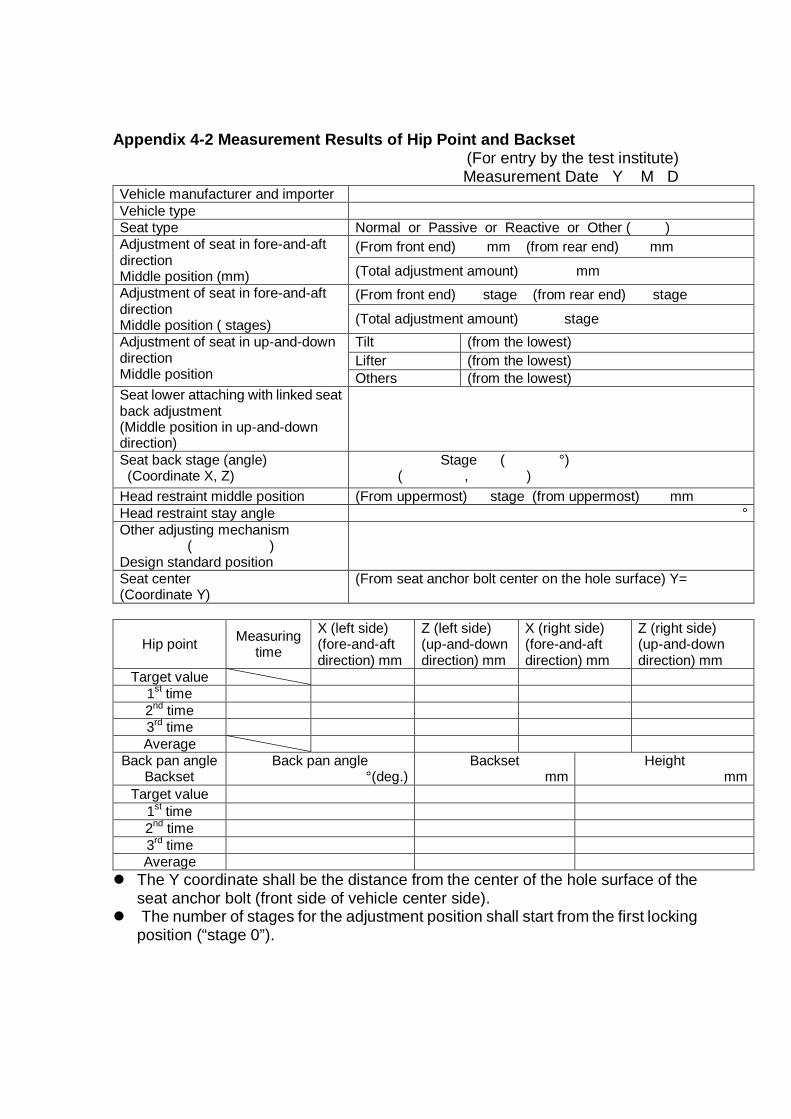
Appendix 4-2 Measurement Results of Hip Point and Backset (For entry by the test institute)
Measurement Date Y M D Vehicle manufacturer and importer Vehicle type Seat type Normal or Passive or Reactive or Other ( ) Adjustment of seat in fore-and-aft direction Middle position (mm)
(From front end) mm (from rear end) mm
(Total adjustment amount) mm Adjustment of seat in fore-and-aft direction Middle position ( stages)
(From front end) stage (from rear end) stage
(Total adjustment amount) stage Adjustment of seat in up-and-down direction Middle position
Tilt (from the lowest) Lifter (from the lowest) Others (from the lowest)
Seat lower attaching with linked seat back adjustment (Middle position in up-and-down direction)
Seat back stage (angle) (Coordinate X, Z)
Stage ( °) ( , )
Head restraint middle position (From uppermost) stage (from uppermost) mm Head restraint stay angle ° Other adjusting mechanism
( ) Design standard position
Seat center (Coordinate Y)
(From seat anchor bolt center on the hole surface) Y=
Hip point Measuring time
X (left side) (fore-and-aft direction) mm
Z (left side) (up-and-down direction) mm
X (right side) (fore-and-aft direction) mm
Z (right side) (up-and-down direction) mm
Target value 1st time 2nd time 3rd time Average
Back pan angle Backset
Back pan angle °(deg.)
Backset mm
Height mm
Target value 1st time 2nd time 3rd time Average
The Y coordinate shall be the distance from the center of the hole surface of the seat anchor bolt (front side of vehicle center side).
The number of stages for the adjustment position shall start from the first locking position (“stage 0”).
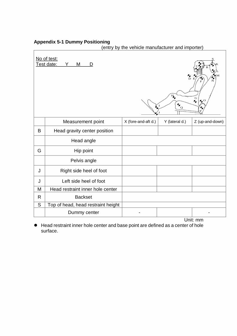
Appendix 5-1 Dummy Positioning (entry by the vehicle manufacturer and importer)
No of test: Test date: Y M D
Measurement point X (fore-and-aft d.) Y (lateral d.) Z (up-and-down)
B Head gravity center position
Head angle
G Hip point
Pelvis angle
J Right side heel of foot
J Left side heel of foot
M Head restraint inner hole center R Backset S Top of head, head restraint height Dummy center - -
Unit: mm Head restraint inner hole center and base point are defined as a center of hole
surface.
ABC
D EF
GH
I
J
K
L
M
N
O
PQ
R
S
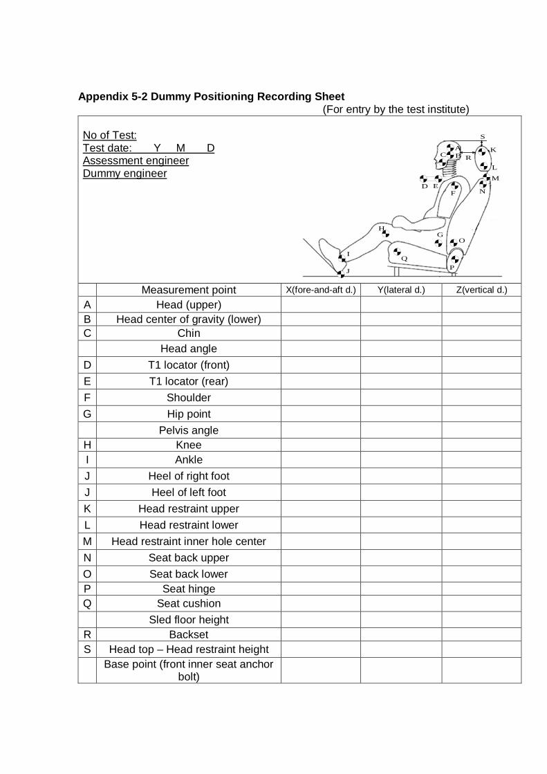
Appendix 5-2 Dummy Positioning Recording Sheet (For entry by the test institute)
No of Test: Test date: Y M D Assessment engineer Dummy engineer
Measurement point X(fore-and-aft d.) Y(lateral d.) Z(vertical d.)
A Head (upper) B Head center of gravity (lower) C Chin Head angle
D T1 locator (front) E T1 locator (rear) F Shoulder G Hip point Pelvis angle
H Knee I Ankle J Heel of right foot J Heel of left foot K Head restraint upper L Head restraint lower M Head restraint inner hole center N Seat back upper O Seat back lower P Seat hinge Q Seat cushion Sled floor height
R Backset S Head top – Head restraint height
Base point (front inner seat anchor bolt)
ABC
D EF
GH
I
J
K
L
M
N
O
PQ
R
S
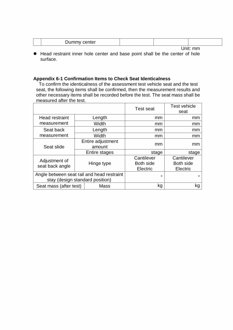
Dummy center Unit: mm
Head restraint inner hole center and base point shall be the center of hole surface.
Appendix 6-1 Confirmation Items to Check Seat Identicalness
To confirm the identicalness of the assessment test vehicle seat and the test seat, the following items shall be confirmed, then the measurement results and other necessary items shall be recorded before the test. The seat mass shall be measured after the test. Test seat Test vehicle
seat Head restraint measurement
Length mm mm Width mm mm
Seat back measurement
Length mm mm Width mm mm
Seat slide Entire adjustment
amount mm mm
Entire stages stage stage
Adjustment of seat back angle Hinge type
Cantilever Both side Electric
Cantilever Both side Electric
Angle between seat rail and head restraint stay (design standard position) ° °
Seat mass (after test) Mass kg kg

Appendix 6-2 Seat Identity Confirmation Check Items (after test)
To confirm identity of test vehicle seat and test seat, following items shall be taken the photographs of seat structure and others then, attached to the following column. Structure of connection area of head restraint and seat back (test seat)
Structure of connection area of head restraint and seat back (test vehicle seat)
Structure of seat frame (test seat)

Structure of seat frame (test vehicle seat)
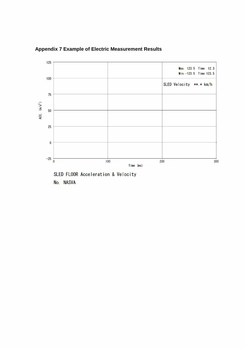
Appendix 7 Example of Electric Measurement Results


300