Embed Size (px)
Citation preview

NEC 2014 and Field Assembled Optical Fiber Cable and Pathways
Marty Adkins, RCDD, CPM, ITIL, INQAL Data Center/Enterprise Application Engineer

NFPA 70 NEC 2014
NEC 2008 Established a New Category of Optical Fiber Cable
Article 770.2 Definitions – Optical Fiber Cable Field-Assembled Optical Fiber Cable: An assembly of one or more optical fibers within a jacket. The jacket, without optical fibers, is installed in a manner similar to conduit or raceway. Once the jacket is installed, the optical fibers are inserted into the jacket, completing the cable assembly. Jacket = Micro Duct Optical Fibers = Micro Fibers

NFPA 70 NEC 2014
Micro Duct / Micro Fiber is
• Not InnerDuct • Not Raceway • Not Cable In Conduit • Field-Assembled Optical Fiber Cable*
*As defined in Article 770.2 and specified in Article 770.179.
NFPA 70 NEC 2014 – Field-Assembled OFC
770.179(F) Field-Assembled Optical Fiber Cable Field-assembled optical fibers shall comply with 770.179(F)(1) through (4)
1. The specific combination of jacket and optical fibers intended to be installed as a field-assembled optical fiber cable shall be listed in accordance with 770.179(A), (B) or (D) and shall be marked in accordance with Table 770.179.
2. The jacket of a field-assembled optical fiber cable shall have a surface marking indicating the specific optical fibers with which it is listed for use.
3. The optical fibers shall have a permanent marking, such as marker tape, indicating the jacket with which they are listed for use.
4. The jacket without fibers shall meet the listing requirements for communications raceways in 800.182(A), (B) or (C) in accordance with the cable marking.

NFPA 70 NEC 2014 – Field-Assembled OFC
“Article 770.179(F)(1) - The specific combination of jacket and optical fibers intended to be installed as a field-assembled optical fiber cable shall be listed in accordance with 770.179(A), (B) or (D) and shall be marked in accordance with Table 770.179.”
770.179(A), (B), (C) OR (D) are the “Listing Requirements”
(A) Types of OFNP and OFCP (B) Types of OFNR and OFCR (C) Types of OFNG and OFCG (D) Types of OFN and OFC
NFPA 70 NEC 2014 – Field-Assembled OFC
800.48 Unlisted Cables Entering Buildings:
Unlisted outside plant communications cables shall be permitted to be installed in building spaces other than risers, ducts used for environmental air, plenums used for environmental air, and other spaces used for environmental air, where the length of the cable within the building, measured from its point of entrance, does not exceed 15m (50 ft.) and the cable enters the building from the outside and is terminated in an enclosure or on a listed primary protector.
NFPA 70 NEC 2014 – Field-Assembled OFC
So What? • Stand Alone Pathway • A Cable that Behaves Like Conduit • Minimalize Splicing • Align Network Growth with Service Requests

Field Assemble Optical Fiber Cable The Medium - Microfiber
Optical Fiber Cable is a cable containing one or more optical fibers that are used to carry light. The optical fiber elements are typically individually coated with plastic layers and contained in a protective tube suitable for the environment where the cable will be deployed. Different types of cable are used for different applications.
A simple model of a telecommunications system has three parts: • Transmitter • Receiver • Medium
In an optical fiber system the medium is, of course, optical fiber.

Pushable Field-Assembled OFC

Field Assembled Optical Fiber Cable – Pushable Connectorized Micro Fiber

Field Assembled Optical Fiber Cable Pushable Connectorized Micro Fiber
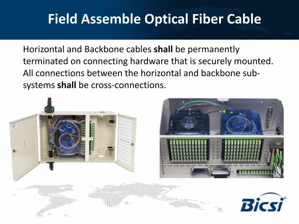
Field Assemble Optical Fiber Cable
Horizontal and Backbone cables shall be permanently terminated on connecting hardware that is securely mounted. All connections between the horizontal and backbone sub-systems shall be cross-connections.

Field Assembled Optical Fiber Cable Cable Pathways Within the Equipment Room (ER)
• Consideration should be given to physical cable management in an access floor environment. High-performance cabling (e.g., optical fiber, balanced twisted-pair, coaxial) shall be properly installed and managed to avoid transmission degradation. For this reason, the use of cable trays or other suitable means for cable management and protection under access flooring is strongly recommended. Care should be taken not to obstruct airflow.
• Optical fiber cables specified to be placed under an access floor or overhead should be placed into a separate trough system specifically designed as an optical fiber cabling pathway in order to protect the cabling from damage.
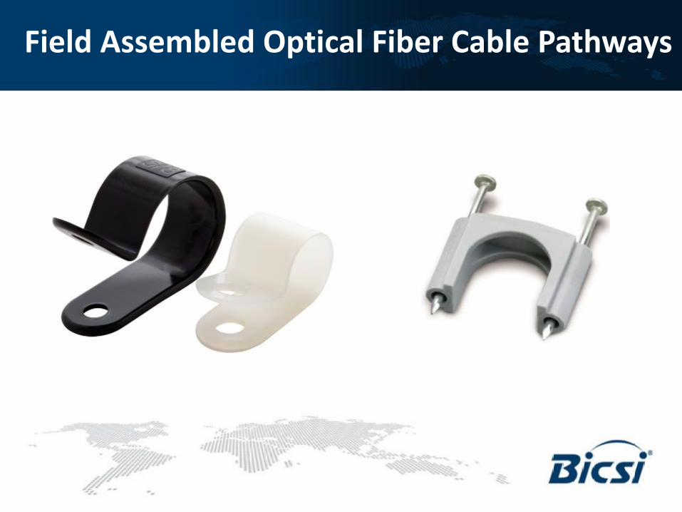
Field Assembled Optical Fiber Cable Pathways

Field Assembled Optical Fiber Cable Pathways

Field Assembled Optical Fiber Cable Enterprise Horizontal Distribution Systems
If the optical fiber outlet is used in the horizontal cabling system/ work area configuration, two balanced, twisted-pair telecommunications outlets/connectors should also be installed rather than one since typical telecommunications cabling work areas currently require both voice and data transmission (usually implemented over balanced twisted-pairs). Thus, the work area configuration made up of only two telecommunications outlets/connectors, one of which is optical fiber, may not allow all user requirements for telecommunications services to be effectively met.

Field Assembled Optical Fiber Cable Horizontal Distribution Systems – Pathways
Horizontal Pathways Include: • Underfloor ducts • Cellular floors • Conduits • Cable trays • Access floors • Ceiling distribution • Surface-mounted raceways • Work area pathways • WLAN APs
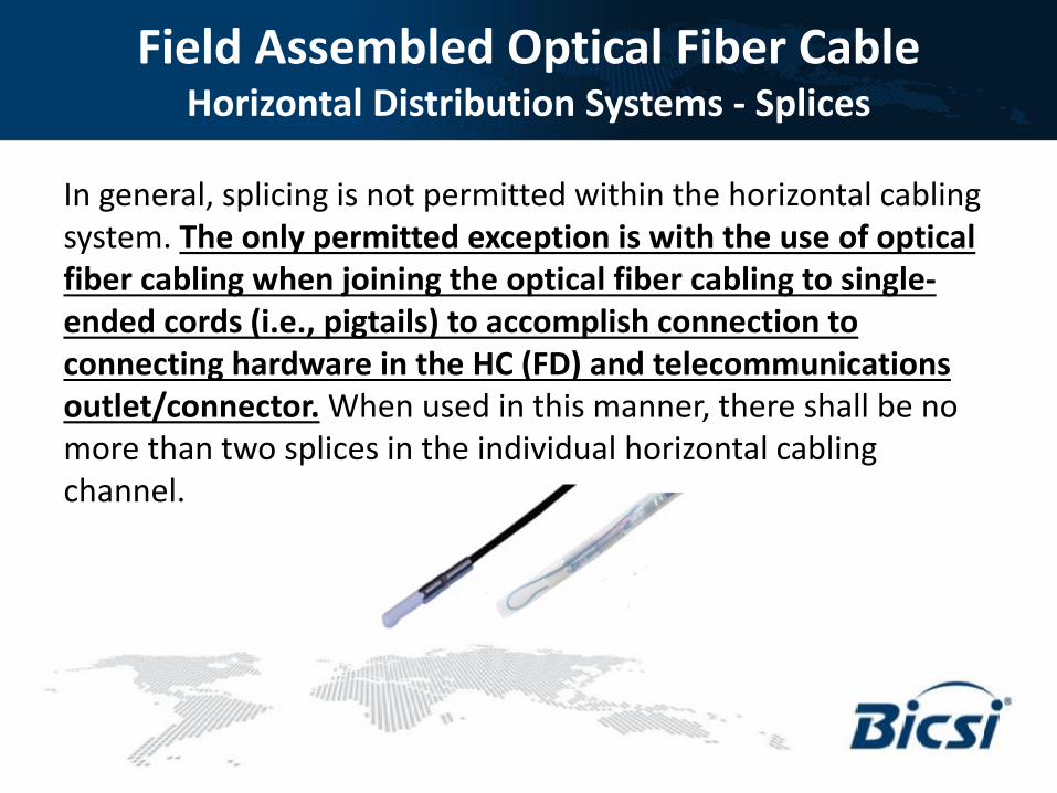
Field Assembled Optical Fiber Cable Horizontal Distribution Systems - Splices
In general, splicing is not permitted within the horizontal cabling system. The only permitted exception is with the use of optical fiber cabling when joining the optical fiber cabling to single-ended cords (i.e., pigtails) to accomplish connection to connecting hardware in the HC (FD) and telecommunications outlet/connector. When used in this manner, there shall be no more than two splices in the individual horizontal cabling channel.
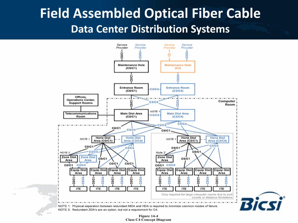
Field Assembled Optical Fiber Cable Data Center Distribution Systems

Field Assembled Optical Fiber Cable Potential Topology with PON

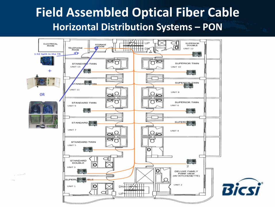
Field Assembled Optical Fiber Cable Horizontal Distribution Systems – PON
As a result of the PON solution’s extended distances it is common to have many optical fiber distribution and demarcation points to transition from OSP to ISP cabling or from backbone to horizontal cabling. At these locations, it may be advantageous to offer a more compact solution that utilizes APC-type connectors. The PON signal is transparent to the connectors utilized, except at the OLT and ONTs. Some solutions may require a high density fiber design, enabling the use of a multi-fiber push-on (MPO) connector.

Field Assembled Optical Fiber Cable Horizontal Distribution Systems – PON
The passive aspect of a PON resides in the splitter. This device provides the ability to split the single fiber output from each PON link exiting the OLT to a variety of splitter ratio outputs, each terminating at the ONT. Split ratio is dependent on the end-users bandwidth needs.

Field Assembled Optical Fiber Cable Horizontal Distribution Systems – PON
Any PON design and deployment shall follow BICSI and Telecommunications Industry Association best practices for cabling installation. As a PON provides multiple interfaces per ONT that exceed the customary two telecommunications outlet/connector requirement to a single work area, a simplex optical fiber cabling connection serves as the permanent link of a PON. PONs commonly utilize a zone-based cabling solution from a ceiling or floor zone box with pre-terminated, simplex, singlemode optical fiber cabling to the actual work area outlets. Since single and dual strand singlemode optical fiber cabling costs about the same, some ITS distribution designers implement a dual strand fiber to each work area outlet to allow for any future growth or potential desktop ONT redundancy options.

Field Assembled Optical Fiber Cable Horizontal Distribution Systems – PON
Backbone Fiber Requirements and Terminations One backbone optical fiber per OLT PON port shall be used per TR. Since there are usually 32 users per PON port, spare capacity should be built-in for future usage. Also, two optical fiber feeder strands to each splitter may be desired to support the redundancy feature. With the design of optical fiber cable in increments of 12, the tubes and ribbons should not be split or shared among TRs.
Field Assembled Optical Fiber Cable Horizontal Distribution Systems – PON
Field Assembled Optical Fiber Cable Horizontal Distribution Systems – PON
Zone Cabling-Based Splitters
Zone cabling splitters offer an alternative to traditional telecommunications space mounted splitters. Since zone cabling splitters are located closer to the end user, this allows for a lower optical fiber implementation cost. If rack space in the floor serving telecommunications space is limited or running multiple strands of optical fiber cabling to a zone is not permitted, placing the splitters in a ceiling-mounted or access floor-mounted enclosure close to the end user outlet locations may be necessary.
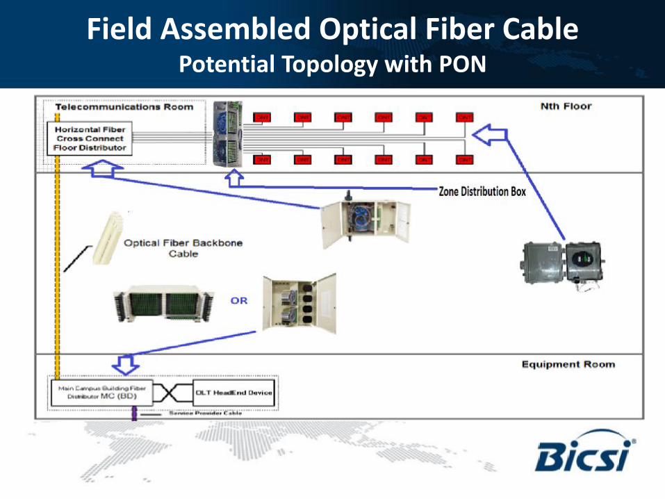
Field Assembled Optical Fiber Cable Potential Topology with PON
Field Assembled Optical Fiber Cable Horizontal Distribution Systems – PON
Testing and Certification of a Passive Optical Network (PON) Infrastructure
All optical fiber cabling within a PON installation should be tested for bi-directional loss at 1310 nm and 1550 nm wavelengths. This should be an end-to-end test, placing one end of the tester at the primary PON singlemode optical fiber jumper cable that would connect to the OLT, through the splitter, and then allow for a reading to be taken on every drop cable at each ONT. In other words, the tester head stays stationary at the OLT end, while the remote is moved across all splitter outputs. It is important to note any major discrepancies in fibers on the same splitter.
Field Assembled Optical Fiber Cable Horizontal Distribution Systems – Pathways
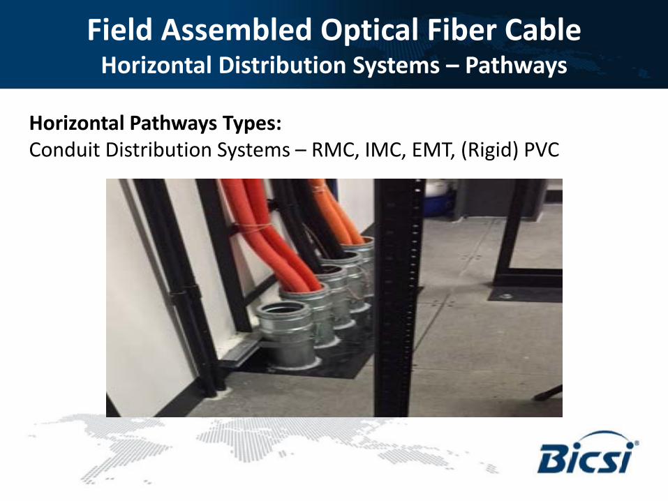
Horizontal Pathways Types: Conduit Distribution Systems – RMC, IMC, EMT, (Rigid) PVC
Field Assembled Optical Fiber Cable Horizontal Distribution Systems – Pathways
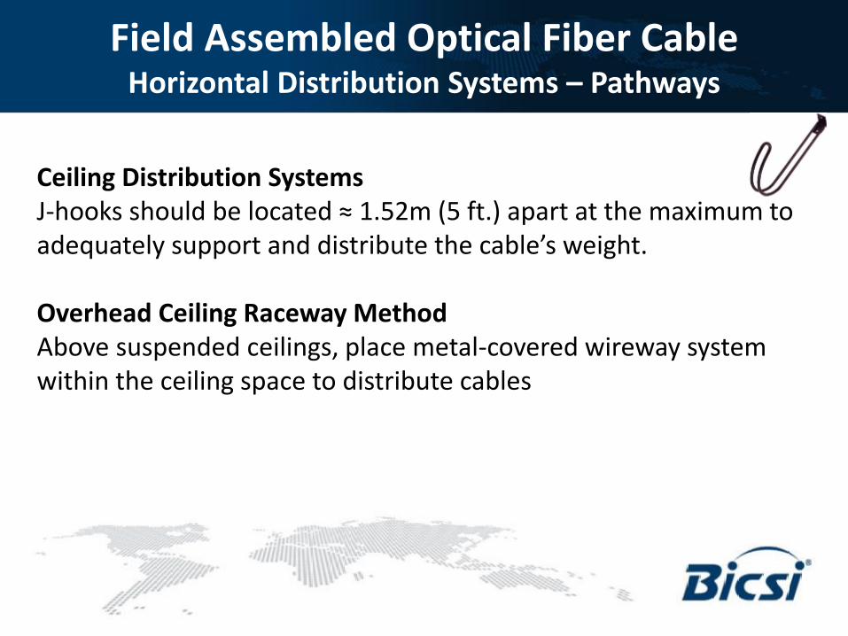
Ceiling Distribution Systems J-hooks should be located ≈ 1.52m (5 ft.) apart at the maximum to adequately support and distribute the cable’s weight. Overhead Ceiling Raceway Method Above suspended ceilings, place metal-covered wireway system within the ceiling space to distribute cables

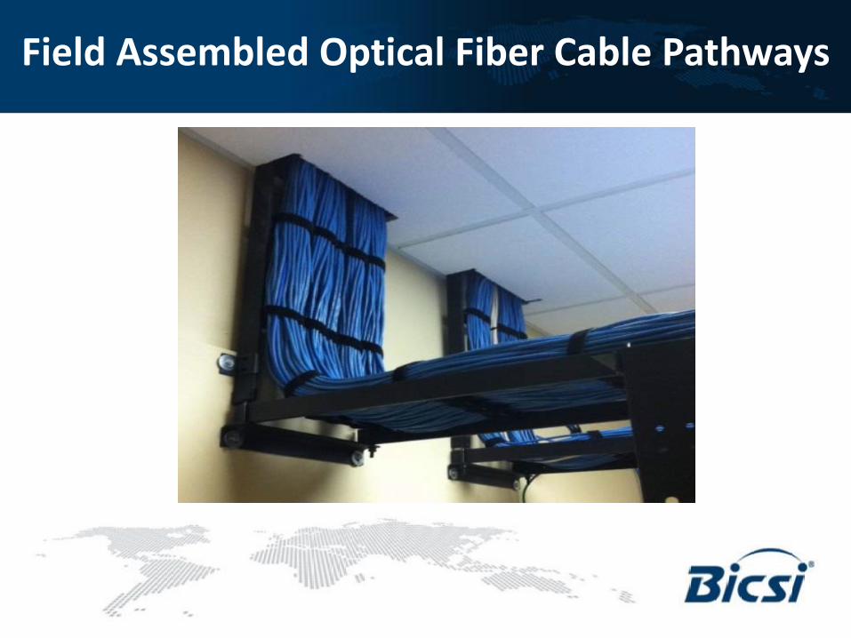
Field Assembled Optical Fiber Cable Pathways
Ceiling Distribution Systems - Ceiling Zones Method: Pathways to each zone may be provided using cable trays within the ceiling area or enclosed conduits or raceways. The raceways, conduits or cable trays should extend from the telecommunications spaces (e.g., ERs, TRs) to the midpoint of the zone. From that point, the pathway should extend to the top of the utility columns or wall conduit.

Field Assembled Optical Fiber Cable Pathways
Field Assembled Optical Fiber Cable Pathways

Field Assembled Optical Fiber Cable Horizontal Distribution Systems – Pathways
Other types of pathways include: • Messenger or support strand • Perimeter (i.e., surface) raceway systems • Furniture pathways • Overfloor ducts • Molding raceways • Poke-thru

Marty Adkins, RCDD, CPM, ITIL, INQAL Data Center/Enterprise Application Engineer
[email protected] (513) 262-7215
Thank You – Q & A