Embed Size (px)
Citation preview
Near-Field Nonuniformities in Angularly-MultiplexedKrF Lasers: The Problem and Possible Solutions
R.H. Lehmberg and Y. Chan
Plasma Physics Division
Naval Research Laboratory
Washington, DC 20375
Induced Spatial Incoherence (ISI) is an effective technique for achieving the high degree of spatial illumination uniformity required for direct-drive fusion. Although ISI provides ultrasmooth illumination at the far-field of the laser, where the target is located, it may still allow the beams to develop significant time-averaged spatial nonuniformities in the quasi near-field. This structure, which arises primarily from random phase distortion and Fresnel diffraction, develops as the KrF beams propagate away from the pupil plane images located at the amplifiers; it is distinct from structure imposed by amplifier gain nonuniformities. Because of the spatial incoherence of ISI beams, the time-integrated structure is significantly smaller than that experienced by coherent beams. Nevertheless, it remains a potential optical damage issue, especially in the long delay paths required for large angularly-multiplexed KrF lasers. This presentation compares simulations and measurements of quasi near-field structure in the Nike KrF laser, and presents simulations showing the options available for controlling the problem in future KrF driver designs.
Supported by USDOE.
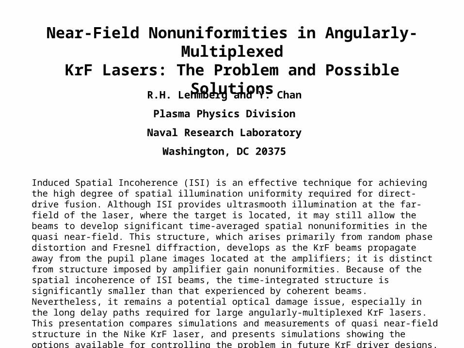
Echelon-free ISI: An incoherent beam is formed at an object aperture in the laser front end, then imaged
through the amplifiers onto a direct-drive ICF target.
ISI concept, showing image-relayed amplifiers placed near the pupil (Fourier plane) of the object. The instantaneous speckle and smooth time-averaged focal profiles at the far-field are illustrated for the case of a flat-top object envelope.
intensity profile of object
instantaneous averaged
image of the object
instantaneous averaged
Target atFar-field
Amplifiers atPupil planes
Aperture
Object Incoherent oscillator
Diffuser
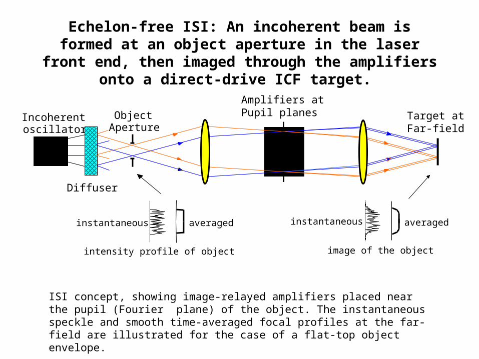
ISI provides ultrasmooth illumination at the far-field ofthe laser, but it may still allow significant time-averaged
spatial structure in the quasi near-field.
This structure is an optical damage issue in the long delay paths requiredfor large angularly-multiplexed KrF lasers.
It arises primarily from random phase distortion in the laser system.
The structure is negligible within the amplifiers, but develops as the beamspropagate downstream to the recollimation and delay optics.
Because of ISI, it remains significantly smaller than that of coherent light.
Here we compare simulations & measurements of quasi near-field structurein Nike, and explore ways to control the problem in future KrF designs.
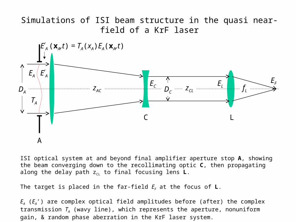
Simulations of ISI beam structure in the quasi near-field of a KrF laser
A
ISI optical system at and beyond final amplifier aperture stop A, showing the beam converging down to the recollimating optic C, then propagating along the delay path zCL to final focusing lens L.
The target is placed in the far-field EF at the focus of L.
EA (EA’) are complex optical field amplitudes before (after) the complex transmission TA (wavy line), which represents the aperture, nonuniform gain, & random phase aberration in the KrF laser system.
C L
zAC fLzCLDA DC
EA E/
A
EC ELEF
TA
E/
A (xA,t) = TA(xA)EA(xA,t)
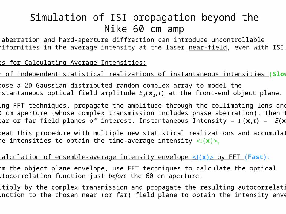
Simulation of ISI propagation beyond the Nike 60 cm amp
Issue: Phase aberration and hard-aperture diffraction can introduce uncontrollable spatial nonuniformities in the average intensity at the laser near-field, even with ISI.
Two Approaches for Calculating Average Intensities:
A. Summation of independent statistical realizations of instantaneous intensities (Slow):
1. Choose a 2D Gaussian-distributed random complex array to model the instantaneous optical field amplitude EO(xO,t) at the front-end object plane.
2. Using FFT techniques, propagate the amplitude through the collimating lens and 60 cm aperture (whose complex transmission includes phase aberration), then to near or far field planes of interest. Instantaneous Intensity = (x,t) = |E(x,t)|2
3. Repeat this procedure with multiple new statistical realizations and accumulate the intensities to obtain the time-average intensity (x)T
B. Direct calculation of ensemble-average intensity envelope (x) by FFT (Fast):
1. From the object plane envelope, use FFT techniques to calculate the optical autocorrelation function just before the 60 cm aperture.
2. Multiply by the complex transmission and propagate the resulting autocorrelation function to the chosen near (or far) field plane to obtain the intensity envelope.
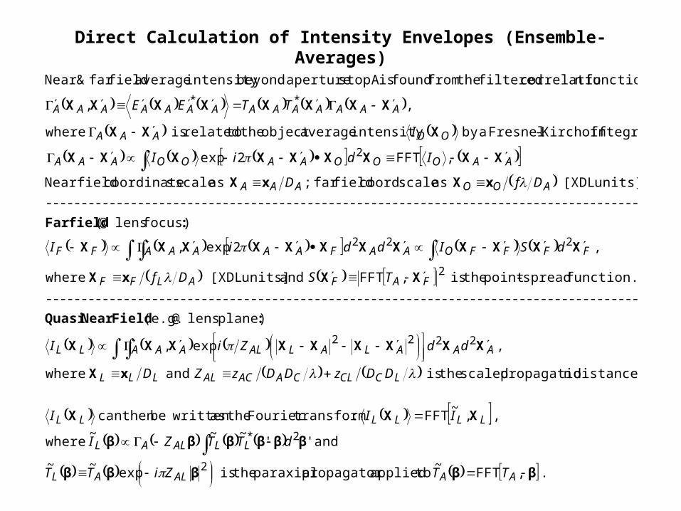
Direct Calculation of Intensity Envelopes (Ensemble-Averages)
. to applied propagator paraxial the is
and where
, :transform Fourier the as writtenbe then can
distance. npropagatio scaled the is and where
plane) lens @ (e.g.
------------------------------------------------------------------------------------
function. spread-point the is and units] [XDL where
focus) lens @
------------------------------------------------------------------------------------
units]. [XDL as scale coord. field far ; as scale scoordinate field Near
integral Kirchoff-Fresnel aby intensity average object the to related is where
function ncorrelatio filtered the from found is A stop aperture beyondintensity average field far & Near
βββββ
ββββββ
XXX
xX
XXXXXXXXX
:FieldNear Quasi
XXxX
XXXXXXXXXXXX
:fieldFar
xXxX
XXXXXXXXX
XXX
XXXXXXXX
,FFT~
exp~~
''~~~
,~
FFT
,exp,
,FFT
,2exp,
(
,FFT2exp
,,
2
2*
2222
2
222
2
**
AAALAL
LLALAL
LLLLLL
LCCLCAACALLLL
AAALALALAAALL
FAFALFF
FFFFOAAFAAAAAFF
AOOAAA
AAOOOAAOOAAA
OOAAA
AAAAAAAAAAAAAA
TTZiTT
dTTZI
III
DDzDDzZD
ddZiI
TSDf
dSIddiI
DfD
IdiI
I
TTEE
Tests show good agreement between envelope & time-averaged intensitiesNike beam 7 with 32 XDL ISI, no phase aberration, average over 8000 tc
Title:C:\HOME\KRF\ISI\ISI1.EPSCreator:Canvas Preview:This EPS picture was not savedwith a preview included in it.Comment:This EPS picture will print to aPostScript printer, but not toother types of printers.
Object
Tests show good agreement between envelope & time-averaged intensitiesbeam 7 with 32 XDL ISI, 7 XDL random phase aberration, average over 8000 tc
Title:NEW_2Creator:Canvas Preview:This EPS picture was not savedwith a preview included in it.Comment:This EPS picture will print to aPostScript printer, but not toother types of printers.
Object
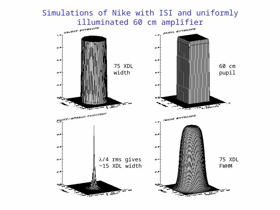
Simulations of Nike with ISI and uniformly illuminated 60 cm amplifier
/4 rms gives~15 XDL width
75 XDLwidth
60 cmpupil
75 XDLFWHM
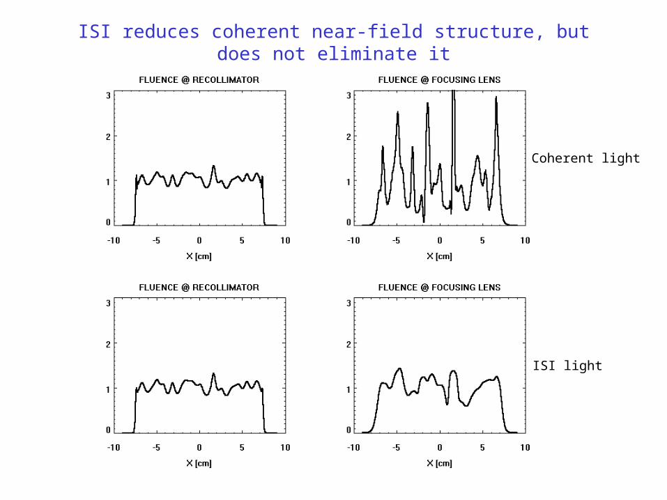
ISI reduces coherent near-field structure, but does not eliminate it
Coherent light
ISI light
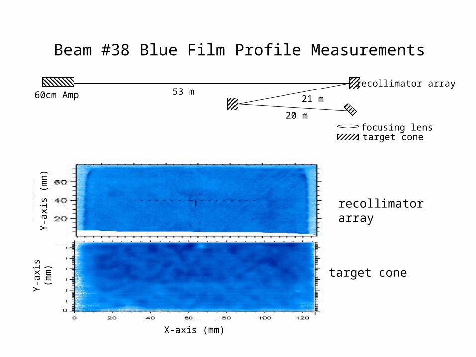
Beam #38 Blue Film Profile Measurements
recollimator array
target cone
60cm Amprecollimator array
target conefocusing lens
53 m21 m
20 m
X-axis (mm)
Y-a
xis
(mm
)Y
-axi
s (m
m)
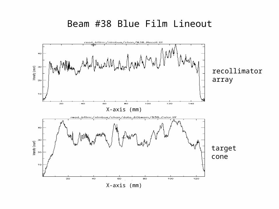
Beam #38 Blue Film Lineout
recollimator array
target cone
X-axis (mm)
X-axis (mm)
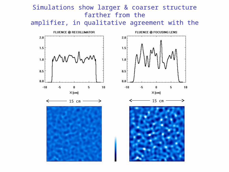
Simulations show larger & coarser structure farther from theamplifier, in qualitative agreement with the measurements
15 cm 15 cm
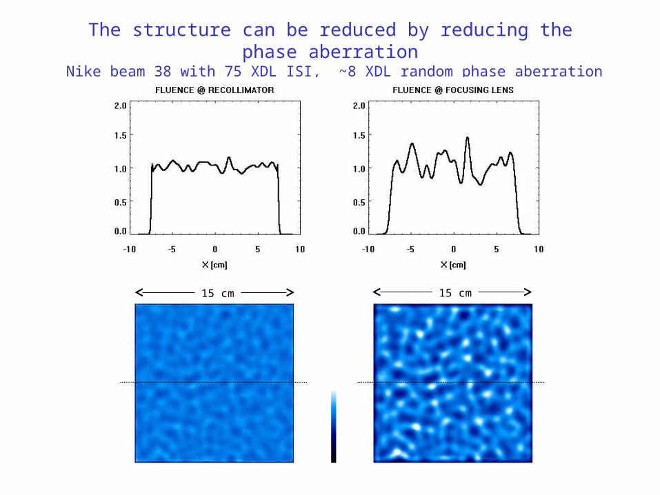
The structure can be reduced by reducing the phase aberration Nike beam 38 with 75 XDL ISI, ~8 XDL random phase aberration
15 cm 15 cm
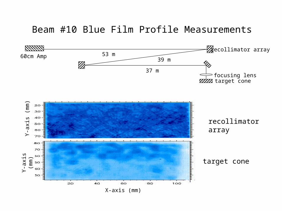
Beam #10 Blue Film Profile Measurements
60cm Amprecollimator array
target conefocusing lens
53 m39 m
37 m
recollimator array
target cone
X-axis (mm)
Y-a
xis
(mm
)Y
-axi
s (m
m)
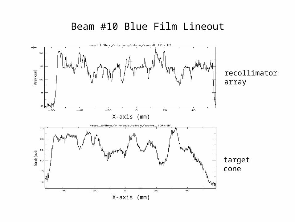
Beam #10 Blue Film Lineout
target cone
X-axis (mm)
recollimator array
X-axis (mm)
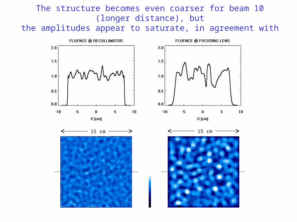
The structure becomes even coarser for beam 10 (longer distance), butthe amplitudes appear to saturate, in agreement with measurements
15 cm 15 cm
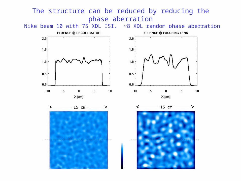
The structure can be reduced by reducing the phase aberration Nike beam 10 with 75 XDL ISI, ~8 XDL random phase aberration
15 cm 15 cm
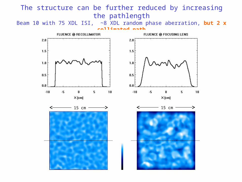
The structure can be further reduced by increasing the pathlengthBeam 10 with 75 XDL ISI, ~8 XDL random phase aberration, but 2 x collimated path
15 cm 15 cm
Summary
Accumulation of random phase aberrations near the 60 cm amplifier creates random fluence nonuniformities at near-field optics downstream (e.g. at the recollimators & focusing lenses), even with ISI beams.
We have developed a fast autocorrelation function formalism to calculate this structure, and benchmarked it against a standard propagation code and measurements on the Nike laser.
With ISI, the hot spots are significantly weaker than those of coherent beams, but they can still become a damage issue for the turning optics and focusing lenses.
Simulations & measurements show that with increasing distance from the amplifier, (a) the scalelengths of the structure increase and (b) the hot spot fluences increase at first, but then appear to saturate and decrease.
The problem can be controlled by reducing phase aberration, using longer recollimated beam paths, and/or beam relaying.
The far-field (image) envelope remains smooth & controllable in all cases.


![arXiv:1104.2903v1 [astro-ph.IM] 14 Apr 2011 · Context.Less than 3% of the known exoplanets were directly imaged for two main reasons. They are angularly very close to their ... Coronagraphs](https://img.pdfslide.us/doc/110x75/5e465b5091efd7150d23bd2b/arxiv11042903v1-astro-phim-14-apr-2011-than-3-of-the-known-exoplanets-were.jpg)


![Single-Crystal Field Effect Transistors An Angularly …ribbon based OFET devices of BT-2TIPS and BT-3TIPS[S7]. Firstly, an individual ribbon standing on the SiO2 surface, as an “organic](https://img.pdfslide.us/doc/110x75/5f29da00a743223cdf458456/single-crystal-field-effect-transistors-an-angularly-ribbon-based-ofet-devices-of.jpg)
![MEMS4 - 1 - MicroAdventure Technologies€¦ · achieved with both grating light valve (GLV) [2,3] ... MEMS4 - 1 Invited IDW ’06 ... nonuniformities present in a given GEMS projection](https://img.pdfslide.us/doc/110x75/5b50b8e37f8b9a346e8f1104/mems4-1-microadventure-achieved-with-both-grating-light-valve-glv-23.jpg)