Embed Size (px)
Citation preview
Near-eye display optic deficiencies and ways to overcome them
Dmitry V. Shmunka
aAlmalence Inc, 3803 Mount Bonnell Rd., Austin, TX, USA 78731-5732
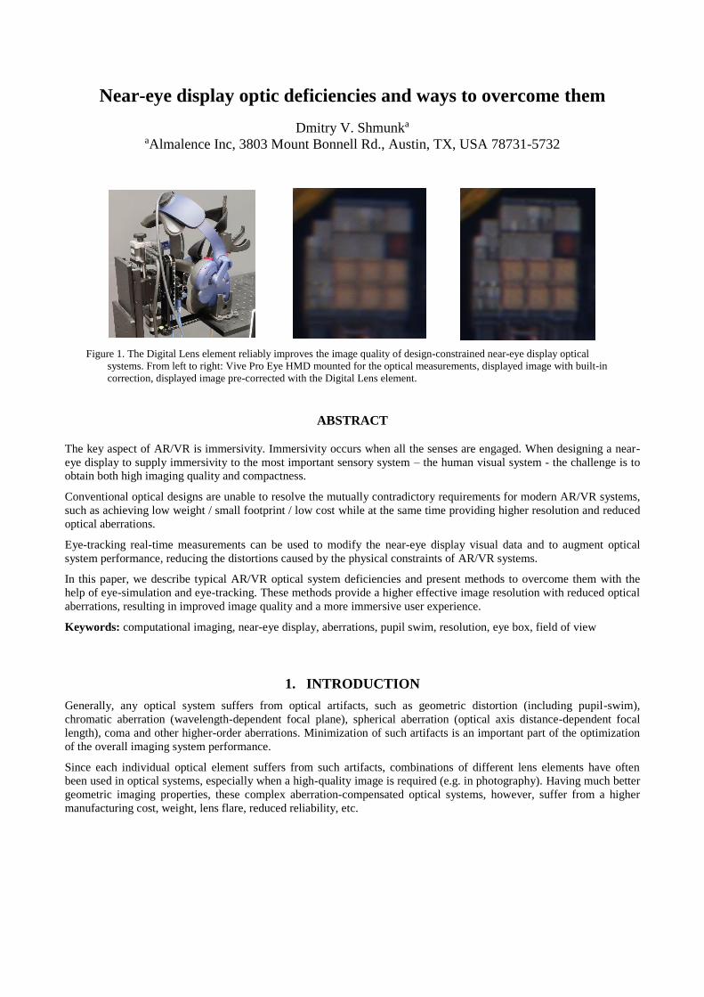
Figure 1. The Digital Lens element reliably improves the image quality of design-constrained near-eye display optical
systems. From left to right: Vive Pro Eye HMD mounted for the optical measurements, displayed image with built-in
correction, displayed image pre-corrected with the Digital Lens element.
ABSTRACT
The key aspect of AR/VR is immersivity. Immersivity occurs when all the senses are engaged. When designing a near-
eye display to supply immersivity to the most important sensory system – the human visual system - the challenge is to
obtain both high imaging quality and compactness.
Conventional optical designs are unable to resolve the mutually contradictory requirements for modern AR/VR systems,
such as achieving low weight / small footprint / low cost while at the same time providing higher resolution and reduced
optical aberrations.
Eye-tracking real-time measurements can be used to modify the near-eye display visual data and to augment optical
system performance, reducing the distortions caused by the physical constraints of AR/VR systems.
In this paper, we describe typical AR/VR optical system deficiencies and present methods to overcome them with the
help of eye-simulation and eye-tracking. These methods provide a higher effective image resolution with reduced optical
aberrations, resulting in improved image quality and a more immersive user experience.
Keywords: computational imaging, near-eye display, aberrations, pupil swim, resolution, eye box, field of view
1. INTRODUCTION
Generally, any optical system suffers from optical artifacts, such as geometric distortion (including pupil-swim),
chromatic aberration (wavelength-dependent focal plane), spherical aberration (optical axis distance-dependent focal
length), coma and other higher-order aberrations. Minimization of such artifacts is an important part of the optimization
of the overall imaging system performance.
Since each individual optical element suffers from such artifacts, combinations of different lens elements have often
been used in optical systems, especially when a high-quality image is required (e.g. in photography). Having much better
geometric imaging properties, these complex aberration-compensated optical systems, however, suffer from a higher
manufacturing cost, weight, lens flare, reduced reliability, etc.
Typically, a near-eye display (NED) takes the form of a display device worn on the head (head-mounted display, or
HMD), that has a small display in front of one or both eyes. In a broader sense, the HMDs can be defined as a device
attached to the user’s head, presenting visual information directly to the eyes, including user’s peripheral vision.
Specifically, due to its wearable nature, the typical NED system employs relatively thin and lightweight VR/AR lenses to
keep the system as inobtrusive to the user as possible. Obviously, using small, lightweight (and relatively inexpensive for
mass-production) optical elements leads to a reduced quality of the optical system, in comparison, for example, to high-
quality lenses, often consisting of dozens individual optical elements.
When designing an HMD, the challenge is to obtain both high imaging quality and compactness. The NED optical
system design space is rather narrow. There are multitude of mutually contradicting requirements and limits. Among
them:
Weight. The system should be as light as possible to avoid user discomfort.
Size. Bulky AR/VR system not only look weird and intrusive, but has high angular momentum, making difficult
to fix HMD position relative to the head while user is moving and affecting user sense of immersiveness due to
additional force needed for head rotation.
Efficiency. High effectiveness of light path from display to eye retina to achieve low power consumption and
avoid heat dissipating onto user.
Large eye-box. Image should look sharp for every person, with large variation in inter-pupillary distance (IPD)
possible between subjects. User looking in directions far from the center of FOV (and therefore having
significant movement of eye-pupil within eye-box) should still see the clear image.
Absence of pupil-swim effects. Dependence of geometry distortion on position of the eye pupil will cause
virtual scene to deform or wobble and is a leading cause of motion sickness and nausea in VR.
Color image clarity – including color constancy independent of pupil position and absence of chromatic
aberrations.
High angular modulation transfer function (MTF). Human 20/20 vision corresponds to roughly 60 PPD.
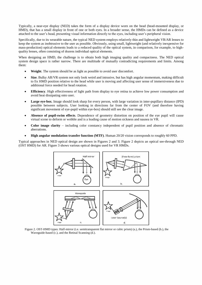
Typical approaches in NED optical design are shown in Figures 2 and 3. Figure 2 depicts an optical see-through NED
(OST HMD) for AR. Figure 3 shows various optical designs used for VR HMDs.
Figure 2. OST-HMD types: Half-mirror (i.e. semitransparent flat mirror or cubic prism) (a.), the Prism-based (b.), the
Waveguide-based (c.), and the Retinal Scanning (d.).
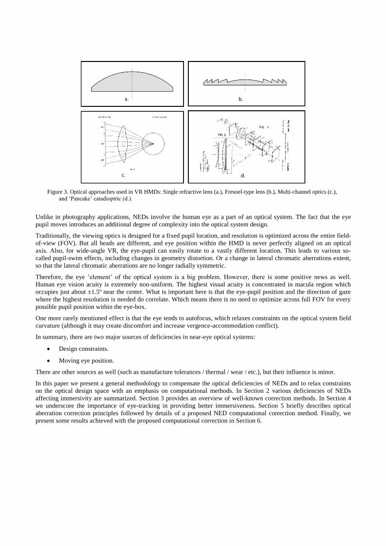
Figure 3. Optical approaches used in VR HMDs: Single refractive lens (a.), Fresnel-type lens (b.), Multi-channel optics (c.),
and ‘Pancake’ catadioptric (d.).
Unlike in photography applications, NEDs involve the human eye as a part of an optical system. The fact that the eye
pupil moves introduces an additional degree of complexity into the optical system design.
Traditionally, the viewing optics is designed for a fixed pupil location, and resolution is optimized across the entire field-
of-view (FOV). But all heads are different, and eye position within the HMD is never perfectly aligned on an optical
axis. Also, for wide-angle VR, the eye-pupil can easily rotate to a vastly different location. This leads to various so-
called pupil-swim effects, including changes in geometry distortion. Or a change in lateral chromatic aberrations extent,
so that the lateral chromatic aberrations are no longer radially symmetric.
Therefore, the eye ’element’ of the optical system is a big problem. However, there is some positive news as well.
Human eye vision acuity is extremely non-uniform. The highest visual acuity is concentrated in macula region which
occupies just about ±1.5º near the center. What is important here is that the eye-pupil position and the direction of gaze
where the highest resolution is needed do correlate. Which means there is no need to optimize across full FOV for every
possible pupil position within the eye-box.
One more rarely mentioned effect is that the eye tends to autofocus, which relaxes constraints on the optical system field
curvature (although it may create discomfort and increase vergence-accommodation conflict).
In summary, there are two major sources of deficiencies in near-eye optical systems:
Design constraints.
Moving eye position.
There are other sources as well (such as manufacture tolerances / thermal / wear / etc.), but their influence is minor.
In this paper we present a general methodology to compensate the optical deficiencies of NEDs and to relax constraints
on the optical design space with an emphasis on computational methods. In Section 2 various deficiencies of NEDs
affecting immersivity are summarized. Section 3 provides an overview of well-known correction methods. In Section 4
we underscore the importance of eye-tracking in providing better immersiveness. Section 5 briefly describes optical
aberration correction principles followed by details of a proposed NED computational correction method. Finally, we
present some results achieved with the proposed computational correction in Section 6.
2. NEAR-EYE DISPLAY DEFICIENCIES
There are multiple things that can go wrong with a near-eye displayed image. Listed below are the metrics which may
affect immersivity.
Immersive NED metrics (influenced by optics design, at least partially):
- Resolution in direction of gaze
- Pupil swim
- Image contrast
- Stray light
- Ghosting
- Lens shading (color/brightness uniformity across FOV)
Display-related (non-optical):
- Mura
- Screen-door
- Contrast
- Motion blur
- Aliasing (rendering-related)
- Illuminant: brightness / uniformity / spectral characteristics
Pupil swim - there are number of associated effects that depend on pupil location. Like variation in geometry distortion,
lateral chromatic aberration changes, color uniformity. Stray light may be caused by Fresnel rings, which create so called
god rays (for which there seem to be no established measurement methodology). Image contrast may also be linked to
stray light.
We will not touch computational correction of display-related deficiencies (such as mura or brightness uniformity) in this
paper. However, even though spectral characteristic is a display metric, as shown below it is very important for the
ability to correct lateral chromatic aberrations.
3. EXISTING COMPUTATIONAL CORRECTION IN NEAR-EYE OPTICS
There are some widely utilized methods of computational correction already used in nearly every AR/VR near-eye
optical system. Namely, correction of lateral chromatic aberrations (LCA) and geometry distortion (GD) correction.
Such correction is achieved simply by scaling or warping either individual color planes of the image to be displayed (for
LCA correction) or all color planes equally (for GD correction).
A single conventional (most often plastic) element (whether a conventional lens or Fresnel), which is used in typical VR
HMD, leads to a high dispersion in the optical system, and consequently to a high level of chromatic aberrations. LCAs
reveal themselves as different color channels hitting retina at different places.
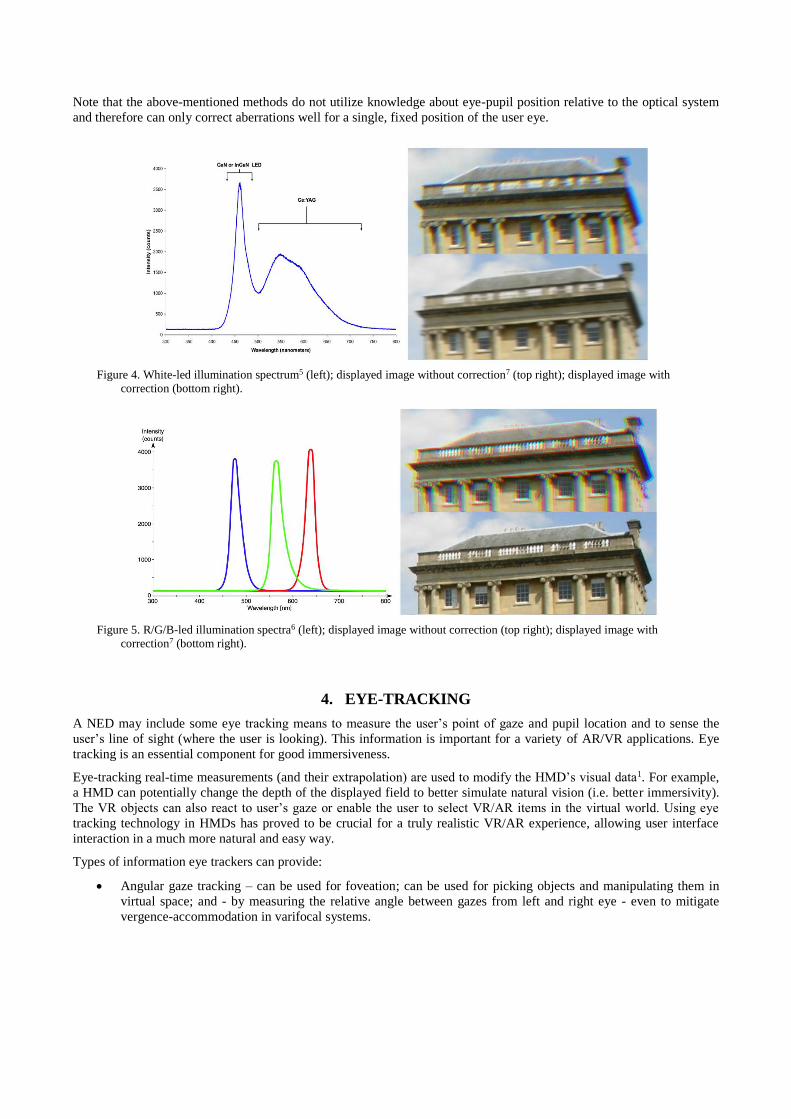
It is interesting to note that selection of the spectral characteristics of the display may greatly influence the effectiveness
of computational aberration correction of LCA. One example of a bad choice of illuminant is shown in Figure 4. The
simple optical system of current VR HMDs will normally produce significant amount of lateral chromatic aberration as
can be seen in the top-right image. It is easily corrected by scaling Red and Blue channels to match the Green channel
magnification as shown in the image at the bottom. But if illuminated by illuminant with a wide (continuous) spectrum,
the smear of individual channels will be high, and it will remain uncorrected (seen as horizontal blur in the bottom
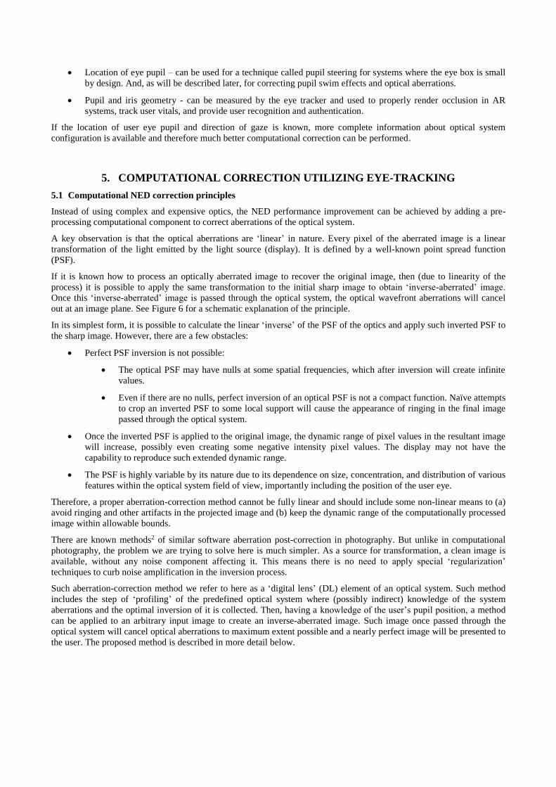
image). A better choice is to illuminate the display with well-separated color spectra instead, such as in R/G/B OLED or
micro-LED (see Figure 5). It can be observed that the chromatic aberration effect with sharp edges is much more visible
(top right image) even though it has the same extent as on Figure 4. However, if color channels are shifted properly
(bottom-right image), color fringes will disappear, and unlike with spread spectrum, the edges will remain sharp.
There are also several straightforward methods to correct aberrations due to manufacturing imperfections. Such as GD
that can be calibrated per unit in VR systems, or constant color non-uniformity correction in waveguide-based AR
systems.
Note that the above-mentioned methods do not utilize knowledge about eye-pupil position relative to the optical system
and therefore can only correct aberrations well for a single, fixed position of the user eye.
Figure 4. White-led illumination spectrum5 (left); displayed image without correction7 (top right); displayed image with
correction (bottom right).
Figure 5. R/G/B-led illumination spectra6 (left); displayed image without correction (top right); displayed image with
correction7 (bottom right).
4. EYE-TRACKING
A NED may include some eye tracking means to measure the user’s point of gaze and pupil location and to sense the
user’s line of sight (where the user is looking). This information is important for a variety of AR/VR applications. Eye
tracking is an essential component for good immersiveness.
Eye-tracking real-time measurements (and their extrapolation) are used to modify the HMD’s visual data1. For example,
a HMD can potentially change the depth of the displayed field to better simulate natural vision (i.e. better immersivity).
The VR objects can also react to user’s gaze or enable the user to select VR/AR items in the virtual world. Using eye
tracking technology in HMDs has proved to be crucial for a truly realistic VR/AR experience, allowing user interface
interaction in a much more natural and easy way.
Types of information eye trackers can provide:
Angular gaze tracking – can be used for foveation; can be used for picking objects and manipulating them in
virtual space; and - by measuring the relative angle between gazes from left and right eye - even to mitigate
vergence-accommodation in varifocal systems.
Location of eye pupil – can be used for a technique called pupil steering for systems where the eye box is small
by design. And, as will be described later, for correcting pupil swim effects and optical aberrations.
Pupil and iris geometry - can be measured by the eye tracker and used to properly render occlusion in AR
systems, track user vitals, and provide user recognition and authentication.
If the location of user eye pupil and direction of gaze is known, more complete information about optical system
configuration is available and therefore much better computational correction can be performed.
5. COMPUTATIONAL CORRECTION UTILIZING EYE-TRACKING
5.1 Computational NED correction principles
Instead of using complex and expensive optics, the NED performance improvement can be achieved by adding a pre-
processing computational component to correct aberrations of the optical system.
A key observation is that the optical aberrations are ‘linear’ in nature. Every pixel of the aberrated image is a linear
transformation of the light emitted by the light source (display). It is defined by a well-known point spread function
(PSF).
If it is known how to process an optically aberrated image to recover the original image, then (due to linearity of the
process) it is possible to apply the same transformation to the initial sharp image to obtain ‘inverse-aberrated’ image.
Once this ‘inverse-aberrated’ image is passed through the optical system, the optical wavefront aberrations will cancel
out at an image plane. See Figure 6 for a schematic explanation of the principle.
In its simplest form, it is possible to calculate the linear ‘inverse’ of the PSF of the optics and apply such inverted PSF to
the sharp image. However, there are a few obstacles:
Perfect PSF inversion is not possible:
The optical PSF may have nulls at some spatial frequencies, which after inversion will create infinite
values.
Even if there are no nulls, perfect inversion of an optical PSF is not a compact function. Naïve attempts
to crop an inverted PSF to some local support will cause the appearance of ringing in the final image
passed through the optical system.
Once the inverted PSF is applied to the original image, the dynamic range of pixel values in the resultant image
will increase, possibly even creating some negative intensity pixel values. The display may not have the
capability to reproduce such extended dynamic range.
The PSF is highly variable by its nature due to its dependence on size, concentration, and distribution of various
features within the optical system field of view, importantly including the position of the user eye.
Therefore, a proper aberration-correction method cannot be fully linear and should include some non-linear means to (a)
avoid ringing and other artifacts in the projected image and (b) keep the dynamic range of the computationally processed
image within allowable bounds.
There are known methods2 of similar software aberration post-correction in photography. But unlike in computational
photography, the problem we are trying to solve here is much simpler. As a source for transformation, a clean image is
available, without any noise component affecting it. This means there is no need to apply special ‘regularization’
techniques to curb noise amplification in the inversion process.
Such aberration-correction method we refer to here as a ‘digital lens’ (DL) element of an optical system. Such method
includes the step of ‘profiling’ of the predefined optical system where (possibly indirect) knowledge of the system
aberrations and the optimal inversion of it is collected. Then, having a knowledge of the user’s pupil position, a method
can be applied to an arbitrary input image to create an inverse-aberrated image. Such image once passed through the
optical system will cancel optical aberrations to maximum extent possible and a nearly perfect image will be presented to
the user. The proposed method is described in more detail below.
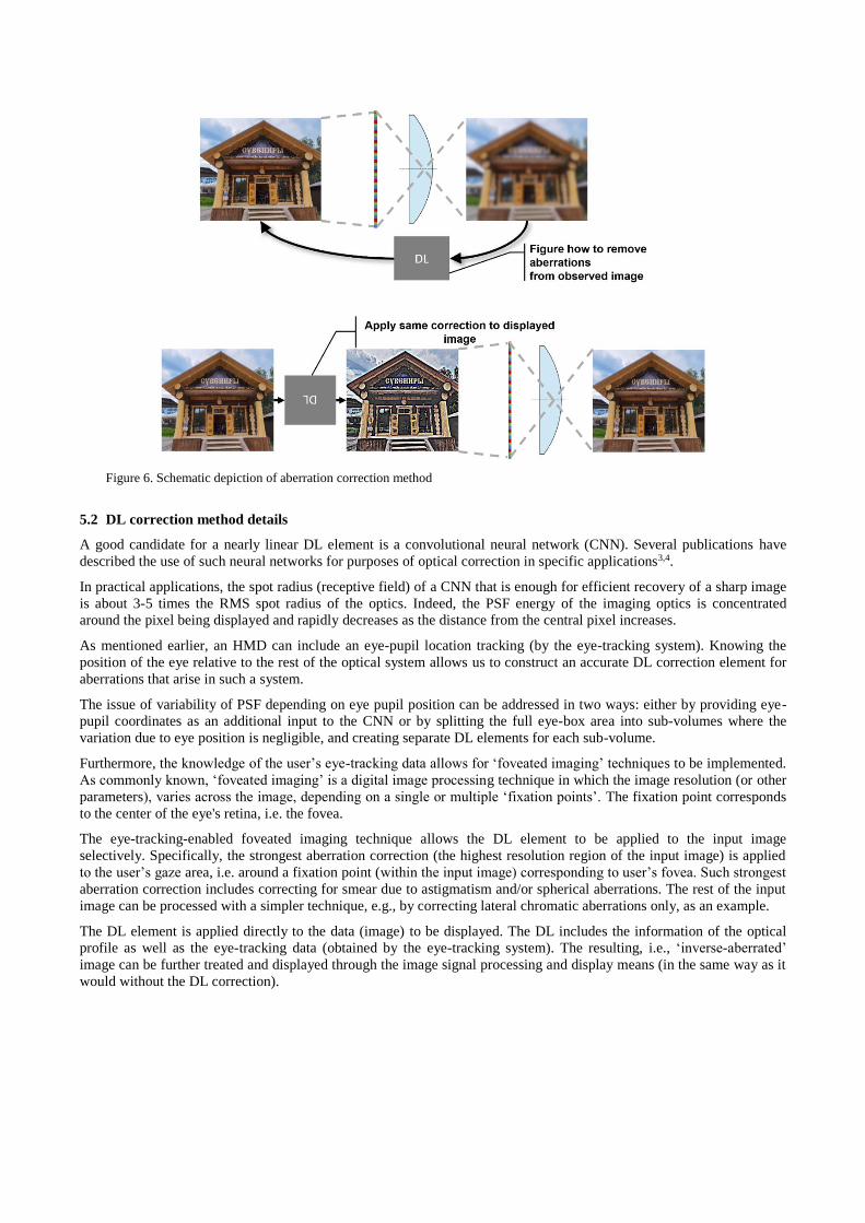
Figure 6. Schematic depiction of aberration correction method
5.2 DL correction method details
A good candidate for a nearly linear DL element is a convolutional neural network (CNN). Several publications have
described the use of such neural networks for purposes of optical correction in specific applications3,4.
In practical applications, the spot radius (receptive field) of a CNN that is enough for efficient recovery of a sharp image
is about 3-5 times the RMS spot radius of the optics. Indeed, the PSF energy of the imaging optics is concentrated
around the pixel being displayed and rapidly decreases as the distance from the central pixel increases.
As mentioned earlier, an HMD can include an eye-pupil location tracking (by the eye-tracking system). Knowing the
position of the eye relative to the rest of the optical system allows us to construct an accurate DL correction element for
aberrations that arise in such a system.
The issue of variability of PSF depending on eye pupil position can be addressed in two ways: either by providing eye-
pupil coordinates as an additional input to the CNN or by splitting the full eye-box area into sub-volumes where the
variation due to eye position is negligible, and creating separate DL elements for each sub-volume.
Furthermore, the knowledge of the user’s eye-tracking data allows for ‘foveated imaging’ techniques to be implemented.
As commonly known, ‘foveated imaging’ is a digital image processing technique in which the image resolution (or other
parameters), varies across the image, depending on a single or multiple ‘fixation points’. The fixation point corresponds
to the center of the eye's retina, i.e. the fovea.
The eye-tracking-enabled foveated imaging technique allows the DL element to be applied to the input image
selectively. Specifically, the strongest aberration correction (the highest resolution region of the input image) is applied
to the user’s gaze area, i.e. around a fixation point (within the input image) corresponding to user’s fovea. Such strongest
aberration correction includes correcting for smear due to astigmatism and/or spherical aberrations. The rest of the input
image can be processed with a simpler technique, e.g., by correcting lateral chromatic aberrations only, as an example.
The DL element is applied directly to the data (image) to be displayed. The DL includes the information of the optical
profile as well as the eye-tracking data (obtained by the eye-tracking system). The resulting, i.e., ‘inverse-aberrated’
image can be further treated and displayed through the image signal processing and display means (in the same way as it
would without the DL correction).
As the result of using a DL element, the contrast and fine details of the aberrated original image become visible, with
color fringes removed. The DL can potentially compensate for all types of aberrations, including longitudinal chromatic
and aberrations causing MTF (modulation transfer function) degradation in the near-eye optical elements.
5.3 DL element creation
In order for a CNN to function as a DL element, it should be trained on pairs of images: one produced by the optical
system (input to the training process) and the other one the display input image (target of the training process). The
optically processed image can be produced by either a physical NED or by using computer-based optical system
simulation.
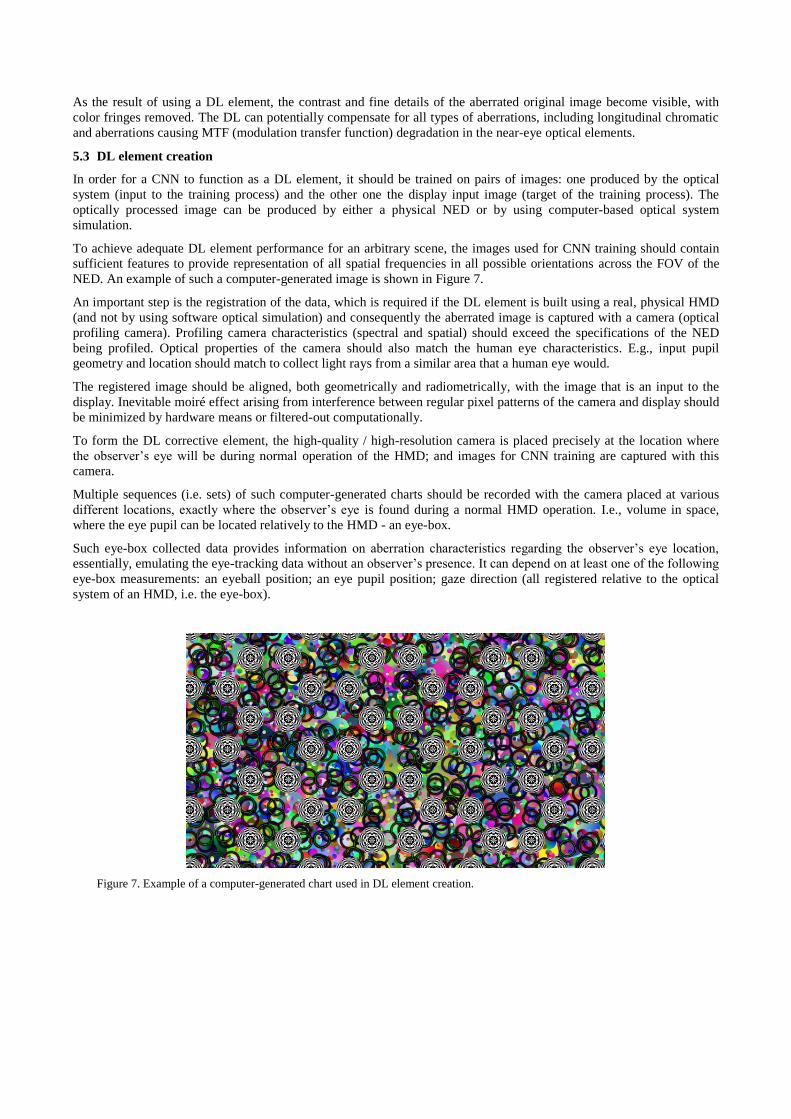
To achieve adequate DL element performance for an arbitrary scene, the images used for CNN training should contain
sufficient features to provide representation of all spatial frequencies in all possible orientations across the FOV of the
NED. An example of such a computer-generated image is shown in Figure 7.
An important step is the registration of the data, which is required if the DL element is built using a real, physical HMD
(and not by using software optical simulation) and consequently the aberrated image is captured with a camera (optical
profiling camera). Profiling camera characteristics (spectral and spatial) should exceed the specifications of the NED
being profiled. Optical properties of the camera should also match the human eye characteristics. E.g., input pupil
geometry and location should match to collect light rays from a similar area that a human eye would.
The registered image should be aligned, both geometrically and radiometrically, with the image that is an input to the
display. Inevitable moiré effect arising from interference between regular pixel patterns of the camera and display should
be minimized by hardware means or filtered-out computationally.
To form the DL corrective element, the high-quality / high-resolution camera is placed precisely at the location where
the observer’s eye will be during normal operation of the HMD; and images for CNN training are captured with this
camera.
Multiple sequences (i.e. sets) of such computer-generated charts should be recorded with the camera placed at various
different locations, exactly where the observer’s eye is found during a normal HMD operation. I.e., volume in space,
where the eye pupil can be located relatively to the HMD - an eye-box.
Such eye-box collected data provides information on aberration characteristics regarding the observer’s eye location,
essentially, emulating the eye-tracking data without an observer’s presence. It can depend on at least one of the following
eye-box measurements: an eyeball position; an eye pupil position; gaze direction (all registered relative to the optical
system of an HMD, i.e. the eye-box).
Figure 7. Example of a computer-generated chart used in DL element creation.
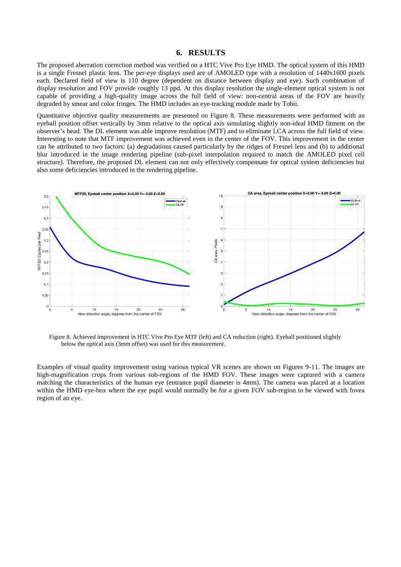
6. RESULTS
The proposed aberration correction method was verified on a HTC Vive Pro Eye HMD. The optical system of this HMD
is a single Fresnel plastic lens. The per-eye displays used are of AMOLED type with a resolution of 1440x1600 pixels
each. Declared field of view is 110 degree (dependent on distance between display and eye). Such combination of
display resolution and FOV provide roughly 13 ppd. At this display resolution the single-element optical system is not
capable of providing a high-quality image across the full field of view: non-central areas of the FOV are heavily
degraded by smear and color fringes. The HMD includes an eye-tracking module made by Tobii.
Quantitative objective quality measurements are presented on Figure 8. These measurements were performed with an
eyeball position offset vertically by 3mm relative to the optical axis simulating slightly non-ideal HMD fitment on the
observer’s head. The DL element was able improve resolution (MTF) and to eliminate LCA across the full field of view.
Interesting to note that MTF improvement was achieved even in the center of the FOV. This improvement in the center
can be attributed to two factors: (a) degradations caused particularly by the ridges of Fresnel lens and (b) to additional
blur introduced in the image rendering pipeline (sub-pixel interpolation required to match the AMOLED pixel cell
structure). Therefore, the proposed DL element can not only effectively compensate for optical system deficiencies but
also some deficiencies introduced in the rendering pipeline.
Figure 8. Achieved improvement in HTC Vive Pro Eye MTF (left) and CA reduction (right). Eyeball positioned slightly
below the optical axis (3mm offset) was used for this measurement.
Examples of visual quality improvement using various typical VR scenes are shown on Figures 9-11. The images are
high-magnification crops from various sub-regions of the HMD FOV. These images were captured with a camera
matching the characteristics of the human eye (entrance pupil diameter is 4mm). The camera was placed at a location
within the HMD eye-box where the eye pupil would normally be for a given FOV sub-region to be viewed with fovea
region of an eye.
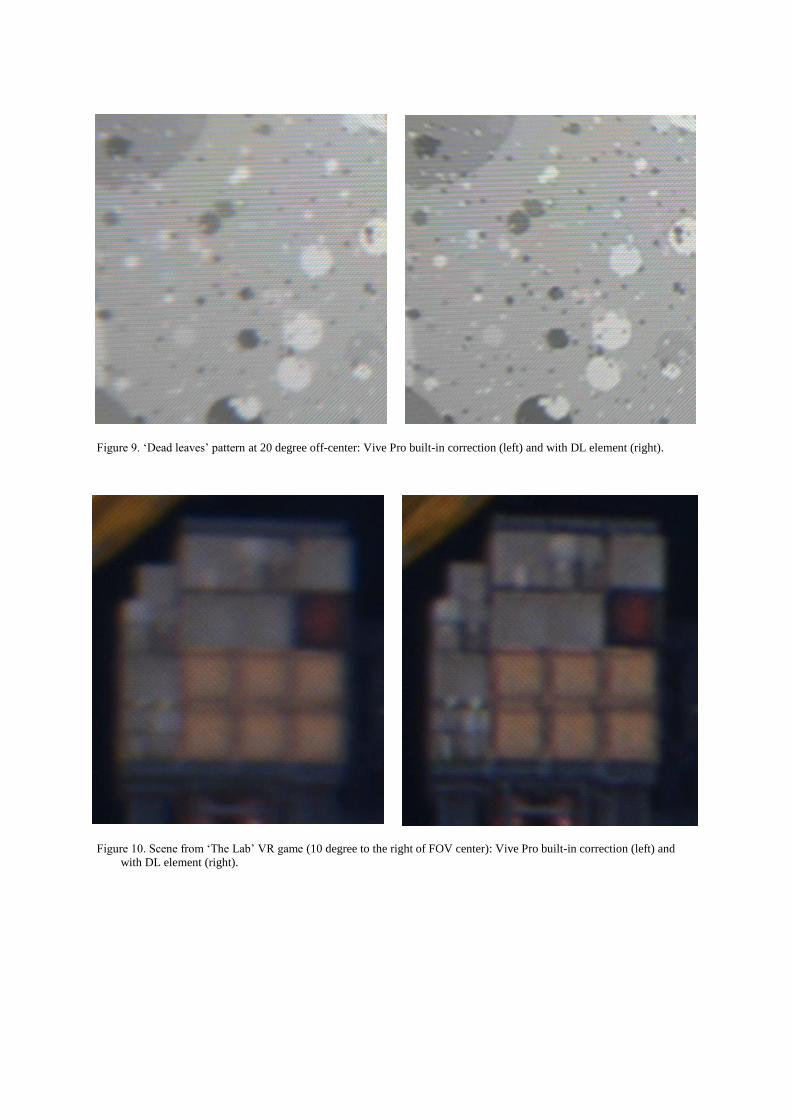
Figure 9. ‘Dead leaves’ pattern at 20 degree off-center: Vive Pro built-in correction (left) and with DL element (right).
Figure 10. Scene from ‘The Lab’ VR game (10 degree to the right of FOV center): Vive Pro built-in correction (left) and
with DL element (right).
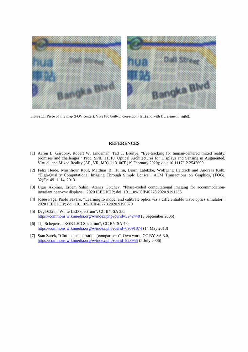
Figure 11. Piece of city map (FOV center): Vive Pro built-in correction (left) and with DL element (right).
REFERENCES
[1] Aaron L. Gardony, Robert W. Lindeman, Tad T. Brunyé, "Eye-tracking for human-centered mixed reality:
promises and challenges," Proc. SPIE 11310, Optical Architectures for Displays and Sensing in Augmented,
Virtual, and Mixed Reality (AR, VR, MR), 113100T (19 February 2020); doi: 10.1117/12.2542699
[2] Felix Heide, Mushfiqur Rouf, Matthias B. Hullin, Björn Labitzke, Wolfgang Heidrich and Andreas Kolb,
“High-Quality Computational Imaging Through Simple Lenses”, ACM Transactions on Graphics, (TOG),
32(5):149–1–14, 2013.
[3] Ugur Akpinar, Erdem Sahin, Atanas Gotchev, “Phase-coded computational imaging for accommodation-
invariant near-eye displays”, 2020 IEEE ICIP; doi: 10.1109/ICIP40778.2020.9191236
[4] Josue Page, Paolo Favaro, “Learning to model and calibrate optics via a differentiable wave optics simulator”,
2020 IEEE ICIP; doi: 10.1109/ICIP40778.2020.9190870
[5] Deglr6328, “White LED spectrum”, CC BY-SA 3.0,
https://commons.wikimedia.org/w/index.php?curid=3242448 (3 September 2006)
[6] Tijl Schepens, “RGB LED Spectrum”, CC BY-SA 4.0,
https://commons.wikimedia.org/w/index.php?curid=69091874 (14 May 2018)
[7] Stan Zurek, “Chromatic aberration (comparison)”, Own work, CC BY-SA 3.0,
https://commons.wikimedia.org/w/index.php?curid=923955 (5 July 2006)


![Sculpting the UMLS Refined Semantic Networkzh2132/Papers/He_OJPHI_2014.pdfThe Refined Semantic Network (RSN) [8,9] was introduced to overcome these two deficiencies of the SN. It has](https://img.pdfslide.us/doc/110x75/607f97f6e9905f59e850b44b/sculpting-the-umls-refined-semantic-zh2132papersheojphi2014pdf-the-refined.jpg)