Embed Size (px)
Citation preview

NEAR EAST UNIVERSITY
Faulty of Engineering
Department of Electrical and Electronic Engineering
PIC PROGRAMMING FOR CONTROL THREE PHASE MOTORS
Graduation Project EE-400
Student Hal is Hakan Ayan(20010893)
Supervisor: ..
~sst.Prof. Ozgur Cemal - Ozerdem
Nicosia-2006

••
ACKNOWLEDGMENTS
First I want to thanks Asst.Prof.Ozgiir Ozerdem to my advisor.Under his guidance.I
successfully overcome many difficulties and learn a lot about PIC (Peripheral Interface
Controller) and motors.In each discussion,he explained my questions patiently,and I felt my
quick progress from his advises.He always helps me alot either in my study or my life.I asked
him many questions in electronics and motors and he always answered my questions quickly and in detail.
Special thanks to Samet Biricik with thier kinds help,i could use three phase motors and roles
successfully .Thanks to Faculty of Engineering for having such a good computational
environment.
I also want to thank my friends in NEU:Fatih Dagci.Mesut Bulut,Fatih Gunde.Kamil
Selek,Alper Karakus.Yahya Goksay.Being with them make my 5 years in NEU full of fun.
Finally,I want to thank my family,especially Aziz Ayan,Fatma Ayan,Filiz Ayan and Funda
Kumbolu.Without their endless support and love for me,I would never achieve my current
position.I wish my mother lives happily always,and my father in the heaven be pround of me.

•
ABSTRACT
In the Project the control of motors by pie was realized. This means that high voltage is
controlled with low voltage.THe cost is very low with pie.If possible LCD screen and IR
could be used for developing the system.
Everyhing is starting to high to led and low to led with pie programming.But the most
important is activate the ports at the same time with the pie.This event was created from the
seven segment display logic.After that a table for ports was created and to see how to
continue to start and to finish the program.
One of the most important part is using the relays. The left side part is control part and
right side is used to operate three phase motors.Wall panel is used to connect the motors to
pie.This wall panel has contactor to trigger the motors.The neutral in the wall is used to
control the motor by pie.
Many more beneficial things can be done by using pie programming in the
industry.Pie have developing logic by engineer so easy to find good and beneficial things.
11

,, •
INTRODUCTION
Never before has it been so quick and easy to create microprocessor-based circuits. With the
advent of the new PIC range of 8-bit microcontrollers and the high performance, low cost
software available, a project can take literally a morning to progress from initial conception to
final prototype.
Developing a PIC-based project takes only six easy steps:
1. Type in the program
2. Assemble the program into a binary file(but we use Pie Basicpro codes)
3. Simulate the program and debug it(in this section we use MicroCode Studio program we
did not want to simulate it.we find the hex decimal doc. with use these program)
4. Load the binary program into the PIC's memory(in this section we use Ic-Prog program)
5. Wire up the circuit
6. Switch on and test.
It's as easy as that!
In the early 1980s, the term PIC stood for Peripheral Interface Controller. These devices were
originally designed for use in applications with 16-bit microprocessors and computer
peripherals,remote control transmitters, domestic products and automotive systems.
While the PIC data sheets are both comprehensive and informative, it is quite difficult and
time consuming for the beginner to wade through the documentation to find out where and
how to start. After reading this project and building the easy projects described, progressing to
more advanced systems with other PIC microcontrollers is quite straightforward.
A microcontroller (or microprocessor) can be viewed as a set of digital logic circuits
integrated on a single silicon 'chip' whose connections and behaviour can be specified and
later altered when required, by the program in its memory. The great advantage of this, is that
in order to change the circuit's structure and operation, all that is needed is a change in the
program - very little, if any, circuit hardware modifications are necessary. An alternative view
is that a microcontroller is a state machine whose logic states are defined by its program. A
microprocessor is the Central Processing Unit (CPU) of a computer and a microcontroller can
be regarded as a microprocessor designed specifically for use in applications where machines
such as automobile engines or washing machines are to be controlled. Often the distinction
between microprocessors and microcontrollers is quite blurred, as there is considerable
overlap these days in the classification of different types of computing devices. A typical
microprocessor is a device used in workstation computers, whereas microcontroller is usually
111
NEAR EAST UNIVERSITY
Faulty of Engineering
Department of Electrical and Electronic Engineering
PIC PROGRAMMING FOR CONTROL THREE PHASE MOTORS
Graduation Project EE-400
Student Hal is Hakan Ayan(20010893)
Supervisor: ..
~sst.Prof. Ozgur Cemal - Ozerdem
Nicosia-2006

••
ACKNOWLEDGMENTS
First I want to thanks Asst.Prof.Ozgiir Ozerdem to my advisor.Under his guidance.I
successfully overcome many difficulties and learn a lot about PIC (Peripheral Interface
Controller) and motors.In each discussion,he explained my questions patiently,and I felt my
quick progress from his advises.He always helps me alot either in my study or my life.I asked
him many questions in electronics and motors and he always answered my questions quickly and in detail.
Special thanks to Samet Biricik with thier kinds help,i could use three phase motors and roles
successfully .Thanks to Faculty of Engineering for having such a good computational
environment.
I also want to thank my friends in NEU:Fatih Dagci.Mesut Bulut,Fatih Gunde.Kamil
Selek,Alper Karakus.Yahya Goksay.Being with them make my 5 years in NEU full of fun.
Finally,I want to thank my family,especially Aziz Ayan,Fatma Ayan,Filiz Ayan and Funda
Kumbolu.Without their endless support and love for me,I would never achieve my current
position.I wish my mother lives happily always,and my father in the heaven be pround of me.
•
ABSTRACT
In the Project the control of motors by pie was realized. This means that high voltage is
controlled with low voltage.THe cost is very low with pie.If possible LCD screen and IR
could be used for developing the system.
Everyhing is starting to high to led and low to led with pie programming.But the most
important is activate the ports at the same time with the pie.This event was created from the
seven segment display logic.After that a table for ports was created and to see how to
continue to start and to finish the program.
One of the most important part is using the relays. The left side part is control part and
right side is used to operate three phase motors.Wall panel is used to connect the motors to
pie.This wall panel has contactor to trigger the motors.The neutral in the wall is used to
control the motor by pie.
Many more beneficial things can be done by using pie programming in the
industry.Pie have developing logic by engineer so easy to find good and beneficial things.
11
,, •
INTRODUCTION
Never before has it been so quick and easy to create microprocessor-based circuits. With the
advent of the new PIC range of 8-bit microcontrollers and the high performance, low cost
software available, a project can take literally a morning to progress from initial conception to
final prototype.
Developing a PIC-based project takes only six easy steps:
1. Type in the program
2. Assemble the program into a binary file(but we use Pie Basicpro codes)
3. Simulate the program and debug it(in this section we use MicroCode Studio program we
did not want to simulate it.we find the hex decimal doc. with use these program)
4. Load the binary program into the PIC's memory(in this section we use Ic-Prog program)
5. Wire up the circuit
6. Switch on and test.
It's as easy as that!
In the early 1980s, the term PIC stood for Peripheral Interface Controller. These devices were
originally designed for use in applications with 16-bit microprocessors and computer
peripherals,remote control transmitters, domestic products and automotive systems.
While the PIC data sheets are both comprehensive and informative, it is quite difficult and
time consuming for the beginner to wade through the documentation to find out where and
how to start. After reading this project and building the easy projects described, progressing to
more advanced systems with other PIC microcontrollers is quite straightforward.
A microcontroller (or microprocessor) can be viewed as a set of digital logic circuits
integrated on a single silicon 'chip' whose connections and behaviour can be specified and
later altered when required, by the program in its memory. The great advantage of this, is that
in order to change the circuit's structure and operation, all that is needed is a change in the
program - very little, if any, circuit hardware modifications are necessary. An alternative view
is that a microcontroller is a state machine whose logic states are defined by its program. A
microprocessor is the Central Processing Unit (CPU) of a computer and a microcontroller can
be regarded as a microprocessor designed specifically for use in applications where machines
such as automobile engines or washing machines are to be controlled. Often the distinction
between microprocessors and microcontrollers is quite blurred, as there is considerable
overlap these days in the classification of different types of computing devices. A typical
microprocessor is a device used in workstation computers, whereas microcontroller is usually
111

•
less powerful and has special features such as PWM (pulse width modulation) and timer
devices integrated on the IC specifically for use in the applications mentioned above.
IV
••
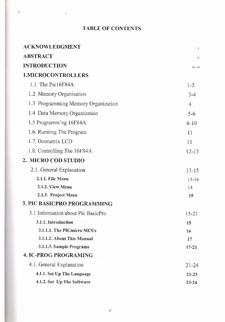
TABLE OF CONTENTS
ACKNOWLEDGMENT
ABSTRACT
INTRODUCTION
1.MICROCONTROLLERS
1.1 The Pic16F84A
1.2 Memory Organisation
1.3 Programming Memory Organization
1.4 Data Memory Organization
1.5 Programm'ng 16F84A
1.6. Running The Program
1 . 7. Dotmatrix LCD
1.8. Controlling The 16F84A
2. MICRO COD STUDIO
2.1. General Explanation
2.1.1. File Menu
2.1.2. View Menu
2.1.3. Project Menu
3. PIC BASICPRO PROGRAMMING
3 .1 Information about Pie BasicPro
3.1.1. Introduction
3.1.1.1. The PICmicro MCUs
3.1.1.2. About This Manual
3.1.1.3. Sample Programs
4. IC-PROG PROGRAMING
4.1. General Explanation
4.1.1. Set Up The Language
4.1.2. Set Up The Software
V
ii
Ill - IV
1-3
3-4
4
5-6
6-10
11
1 1
12-13
13-15
13-14
14
15
15-21
15
16
17
17-21
21-24
21-23
23-24
5. PIC PROGRAMMING DEVICE
5 .1 General Explanation
6. BACKGROUND OF MY PROJECT
6.1. Relays
6.1.1. The Using Of Relay in My Project
6.1.2 .Example Of Relay
6.2. Transistor
6;2.1.Types of transistor
6.2.2 .Connecting
6.2.3.Choosing a transistor
6.3. Capacitor
6.3.1. Capacitor Types
6.3.2. Ceramic Capacitors
6.3.3. Aluminum Oxide
6.3.4. Tantalium Oxide Capacitors
6.4. Switch Buttons
6.5. Crystals
6.6. Resistors
6. 7 .AC motors
6.7.1. Three-phase AC synchronous motors
6.7.2. Single-phase AC induction motors
6.7.2.1. Single-phase AC synchronous motors
7. MY PROJECT
7.1. View of my Project
7 .2. Pie Basic Pro codes and explanation
.................................................................................... CONCLUSION
REFERENCES
Vl
25
26-29
26
26-29
30-34
30
31
31-34
35-38
35-36
36
37
37
38
39-40
40-41
42-48
46
47-48
48
49
49-51
•
1.MICROCONTROLLERS
It is a microcomputer used for precise process control, in data handling,
communication, and manufacturing . .It is first programmed and later used for any
application.
Some important features of Pic16F84 willbe discussed in this section. Since the Pie
16F84A itself may not be explained completely in hudreds of pages, there will not be
much details in this project about it. This section simply indroduce the Pic16F84A, its
registers.This section also introduces how to programe the Pic16F84.
1.1. The Piel 6F84A
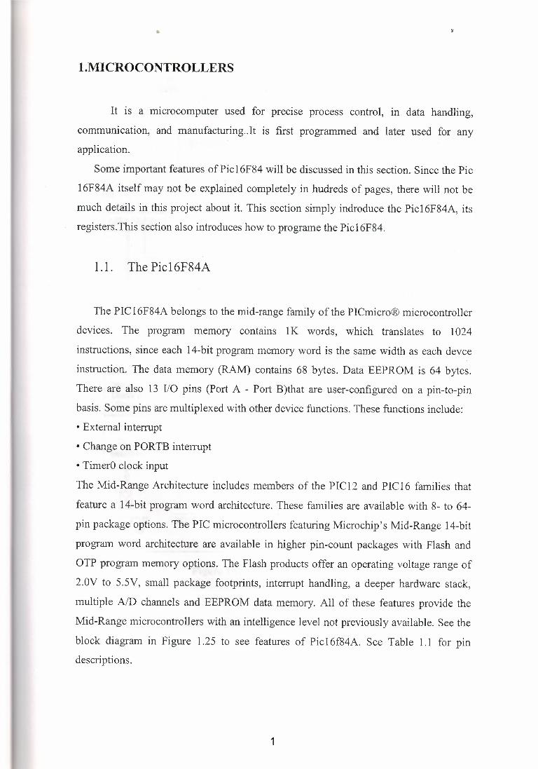
The PIC 16F84A belongs to the mid-range family of the PICmicro® microcontroller
devices. The program memory contains 1 K words, which translates to 1024
instructions, since each 14-bit program memory word is the same width as each devce
instruction. The data memory (RAM) contains 68 bytes. Data EEPROM is 64 bytes.
There are also 13 I/0 pins (Port A - Port B)that are user-configured on a pin-to-pin
basis. Some pins are multiplexed with other device functions. These functions include:
• External interrupt
• Change on PORTB interrupt
• TimerO clock input
The Mid-Range Architecture includes members of the PIC12 and PIC16 families that
feature a 14-bit program word architecture. These families are available with 8- to 64-
pin package options. The PIC microcontrollers featuring Microchip's Mid-Range 14-bit
program word architecture are available in higher pin-count packages with Flash and
OTP program memory options. The Flash products offer an operating voltage range of
2.0V to 5.5V, small package footprints, interrupt handling, a deeper hardware stack,
multiple ND channels and EEPROM data memory. All of these features provide the
Mid-Range microcontrollers with an intelligence level not previously available. See the
block diagram in Figure 1.25 to see features of Piel 6f84A. See Table 1.1 for pin descriptions.
1

••
~ · · · PftGram Counter k· Diita Bus a, / ,I FLJi.SH Pto,am Memory
1K:i: 14
lrrstru ciion Regis IE r
!J
5 Direc:tAddr
P.AM File Registers
68x8
RAMAddr
In sea Addr
FSR reg
I STATUS reg
I rrstruc1ion Decooe& Control
T1r1ing Generalioo
OSC2/CLKOUT OSC1!CLVJN
Power-up limer
Oscillitor stilt-up limer
Pf/Wef-cm Reset
EE PROM Dilta Meroory
EEPROM EEDA TA ~ Da1a Merm11y
ehB
EEADR
W.atr:~ag Timer
TMRD
RA4rIDCKI
8 110 f)orts
MClR Vaa, Vas
Figure 1.1. Features of PIC16F84A
2
"
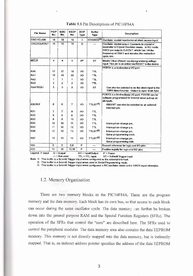
Table 1.1 Pin Descriptions of PIC 16F84A
Pin Name POI? SOIC SSOP UOfP Buffer Description No. No. No. Type Type
OSC11'CLK.IN' 16 16 18 I STJCMosl3> Oscillator crystal .inJJ(lllextemal dOO:k .soun::e input. OSC21'CU<OUT 15 15 1 {l 0 - Oscillator cryslaJ output Connects to crystal or
resona1or in Crystal Oscillator mode. In RC mode, OSC2 pin oulpu!ls Cl..KOUT, which has 1/4 the frequency of OSC 1 sr,d denotes the ,ins1ruclion cydera-te.
MCLR 4 4 4 1/P ST Ml3Slet"Clear (Reset) input/programming vollege input. This pinls an active low RESET to the device. PORTA is a bi-directional 1K) port.
RAO 17 17 19 eo TIL RA1 18 18 20 eo TIL
RA2 1 1 1 IJO TIL RA3 2 2 2 £JO TIL RA4rTOCKI 3 a 3 £JO ST Can also be selecled ta De the ciool! input to the
TMRO timer/counter. Output is open drain type. PORTS Js a. bi-directional IIO pert, PORTB can be software prcgran:vned for internal weak pulkip on al inputs.
RBOIJNT e 6 7 IJO TTUSTl1r RBOJl'NT can a'9o be seleciecj as Ell'! external inter,rupt pin.
RB1 7 7 a IJO TIL RB2 a a {l fJO TIL RB3 {l G 10 IJO TIL RB4 10 10 l1 1/0 TTL lnterrupt-011--cliange pin. RB6 11 11 12 110 TTL lnterrupt-011--cliange pin. RBe 12 12 1a fJO Tll1S7'2l lnterrupt-on--crlange pin.
Serial programming clock. RB7 13 13 14 110 TTUSTl2} lnterrupt-on--crlange pin.
Serial programming data. v~ 6 5 5.6 p - Ground referenoe flll" lo9ic: end 110 pm,s. VDD 14 14 16, 16 p - Positive supply for logic: a.nd IIO ;p.,s. Le,gend: I= m,put O = Ouip.ul 110 = tnpul/0\llput P = Power
- = Not used TTL = TTL input ST = Scllmitl Trigg.er input Note 1: This trnffer is a Schmitt Trigger input when con-figured as the -external interrupt.
2: This t>u,ffer is a Schmitt Trigger input when used ., Serial Programming made. J: This t:lau,ffer is a Schmitt Trigger input when coniig.ured in RC osc.illalor mode and a CMOS -,put olherwise.
1.2. Memory Organisation
There are two memory blocks in the PIC16F84A. These are the program
memory and the data memory. Each block has its own bus, so that access to each block
can occur during the same oscillator cycle. The data memory can further be broken
down into the general purpose RAM and the Special Function Registers (SFRs). The
operation of the SFRs that control the "core" are described here. The SFRs used to
control the peripheral modules The data memory area also contains the data EEPROM
memory. This memory is not directly mapped into the data memory, but is indirectly
mapped. That is, an indirect address pointer specifies the address of the data EEPROM
3
•
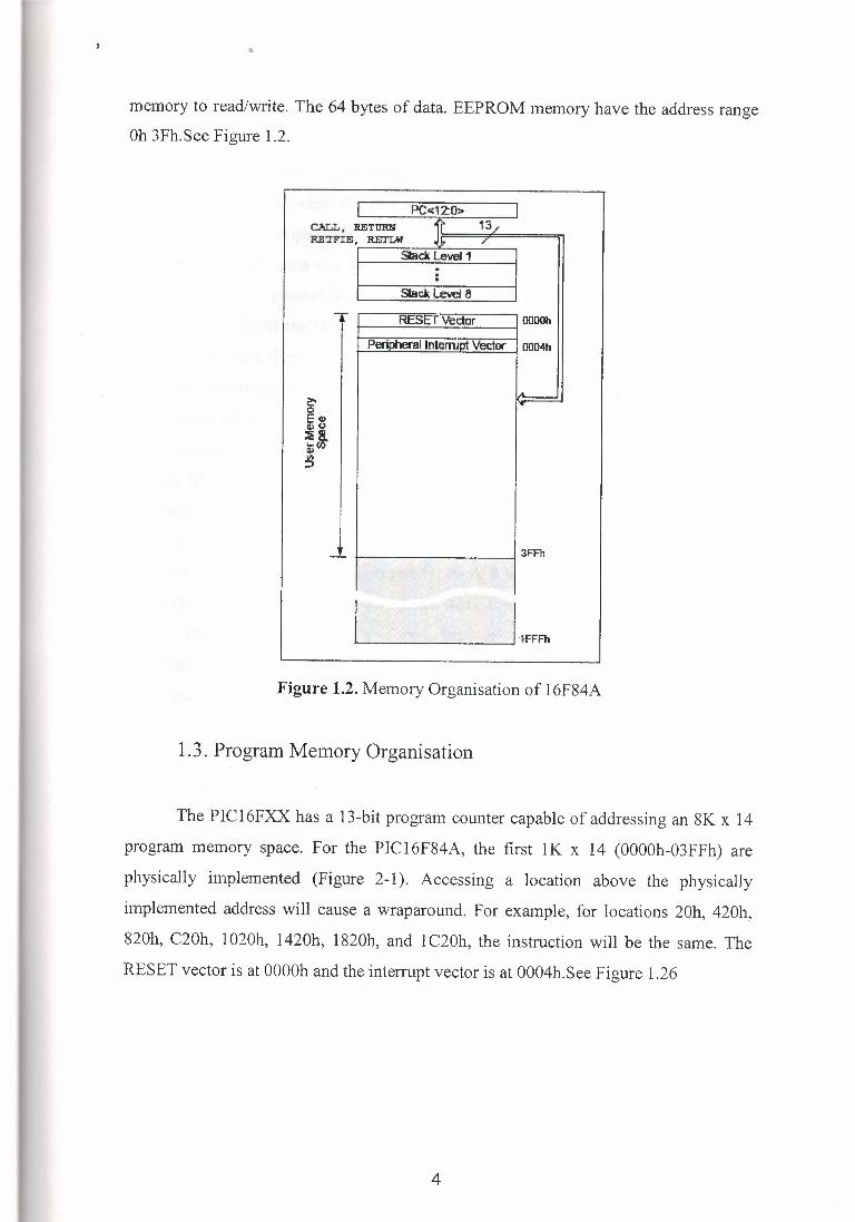
memory to read/write. The 64 bytes of data. EEPROM memory have the address range Oh 3Fh.See Figure 1.2.
CALL , RETURN , ( 13 / Rl!'l'FIE, RETI:N1 ,IJ.===7.6====,;-,11
Slack level 1
Slack level 8
Figure 1.2. Memory Organisation of 16F84A
1.3. Program Memory Organisation
The PIC16FXX has a 13-bit program counter capable of addressing an 8K x 14
program memory space. For the PIC16F84A, the first lK x 14 (OOOOh-03FFh) are
physically implemented (Figure 2-1). Accessing a location above the physically
implemented address will cause a wraparound. For example, for locations 20h, 420h,
820h, C20h, 1020h, 1420h, 1820h, and 1 C20h, the instruction will be the same. The
RESET vector is at 0000h and the interrupt vector is at 0004h.See Figure 1.26
4
•• }'
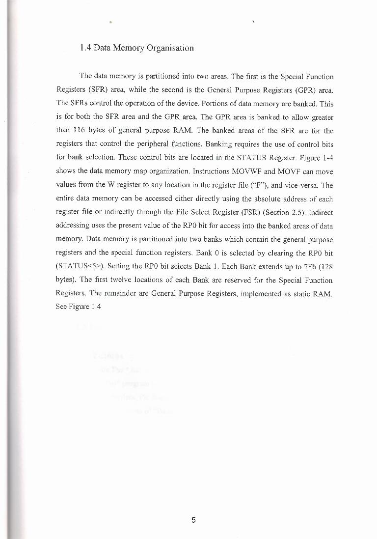
1.4 Data Memory Organisation
The data memory is partitioned into two areas. The first is the Special Function
Registers (SFR) area, while the second is the General Purpose Registers (GPR) area.
The SFRs control the operation of the device. Portions of data memory are banked. This
is for both the SFR area and the GPR area. The GPR area is banked to allow greater
than 116 bytes of general purpose RAM. The banked areas of the SFR are for the
registers that control the peripheral functions. Banking requires the use of control bits
for bank selection. These control bits are located in the STATUS Register. Figure 1-4
shows the data memory map organization. Instructions MOVWF and MOVF can move
values from the W register to any location in the register file ("F"), and vice-versa. The
entire .data memory can be accessed either directly using the absolute address of each
register file or indirectly through the File Select Register (FSR) (Section 2.5). Indirect
addressing uses the present value of the RPO bit for access into the banked areas of data
memory. Data memory is partitioned into two banks which contain the general purpose
registers and the special function registers. Bank O is selected by clearing the RPO bit
(STA TUS<5> ). Setting the RPO bit selects Bank 1. Each Bank extends up to 7Fh (128
bytes). The first twelve locations of each Bank are reserved for the Special Function
Registers. The remainder are General Purpose Registers, implemented as static RAM.
See Figure 1.4
5
•
File Address Rle Address 00h Indirect oodrJ'l Indirect addrJ1l OOh
01h lM'«l OPTION REG 81h 02h PCL PCL 82h
03h STATUS STATlJS 83h
04h FSR FSR 84h 05h PORTA TRISA 85h
06h PORTB TRIS6 OOh 07h - - 87h 06h EEJATA EECON1 88h 09h EEADR EEC~, I 89h
OAh PCLAlli PC LATH 8Ah
Ol3h INTCON INT CON 8Bh 0~ 8~
4~ c~ 50h DOh
,~L 1~~m Banko Ban~ 1
D Unirl'µemerrted datB menoy locali:Jn, read as 'O'. Note 1: Not a ~I register.
Figure 1.4 Data Memory Organisation of 16F84A
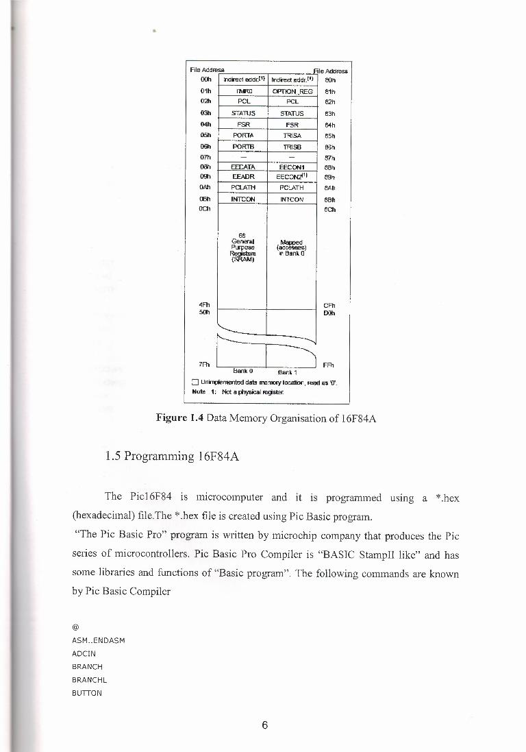
1.5 Programming 16F84A
The Pic16F84 is microcomputer and it is programmed using a *.hex
(hexadecimal) file.The *.hex file is created using Pie Basic program.
"The Pie Basic Pro" program is written by microchip company that produces the Pie
series of microcontrollers. Pie Basic Pro Compiler is "BASIC StampII like" and has
some libraries and functions of "Basic program". The following commands are known
by Pie Basic Compiler
@
ASM .. ENDASM
ADCIN
BRANCH
BRANCHL
BUTTON
6

CALL
CLEAR
CLEARWDT
COUNT
DATA
DTMFOUT
EEPROM
END
FREQOUT
FOR-NEXT
GOSUB
GOTO
HIGH
HS ERIN
HPWM
HSEROUT
I2CREAD
I2CWRITE
INPUT
IF-THEN-ELSE
LCDOUT
LCD IN
{LET}
LOOKDOWN
LOOKDOWN2
LOOKUP
LOOKUP2
LOW
NAP
OUTPUT
OWIN
OW OUT
PAUSE
PAUSEUS
POT
PULSIN
PULSOUT
PWM
RANDOM
RCTIME
READ
READCODE
RETURN
REVERSE
SELECT-CASE
SERIN
SERIN2
SE ROUT
7
•
SEROUT2
SHIFTIN
SHIFTOUT
SLEEP
SOUND
STOP
SWAP
TOGGLE
WRITE
WRITECODE
WHILE-WEND
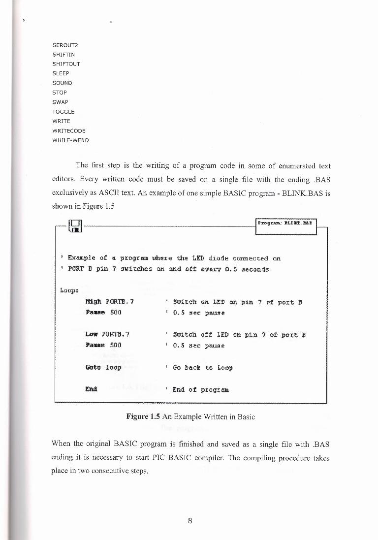
The first step is the writing of a program code in some of enumerated text
editors. Every written code must be saved on a single file with the ending .BAS
exclusively as ASCII text. An example of one simple BASIC program - BLINK.BAS is
shown in Figure 1.5
~ Pl:og-rM'l.! BLI5I. MS
1 £xuple of a p:coguno. uhere the l.Er, diode. connected on 1 PORT B pin 7 switches on and see eve1.-y e. s seconds
Loop: Hip. P 00.'te ~ 7 Paue SOO
1 Stn.tch on LtD on pin 7 of port ii 1 0.5 ~f!C patue
Low PORTB. '7 t>aue SOO
1 $witch off LED on pin 7 of po:rt- ! 1 O •. 5 sec pause
Goto loop 1 C,o back to Loop
Figure 1.5 An Example Written in Basic
When the original BASIC program is finished and saved as a single file with .BAS
ending it is necessary to start PIC BASIC compiler. The compiling procedure takes
place in two consecutive steps.
8
••
Step 1. In the first step compiler will convert BAS file in assembler s code and save it as BLINK.ASM file.
Step 2. In the second step compiler automatically calls assembler, which converts ASM
- type file into an executable HEX code ready for reading into the programming
memory of a microcontroller. The transition between first and second step is for a user -
programmer an invisible one, as everything happens completely automatically and is
thereby wrapped up as an indivisible process. In case of a syntax error of a program
code, the compilation will not be successful and HEX file will not be created at all.
Errors must be then corrected in original BAS file and repeat the whole compilation
process. The best tactics is to write and test small parts of the program, than write one
gigantic of 1000 lines or more and only then embark on error finding. As a result of a
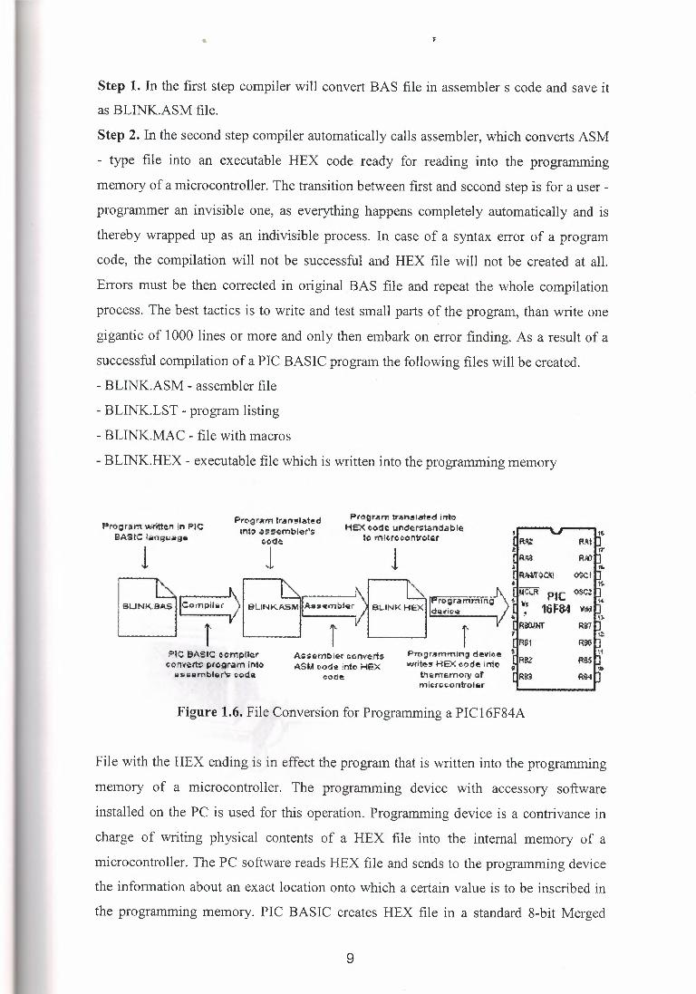
successful compilation of a PIC BASIC program the following files will be created.
- BLINK.ASM - assembler file
- BLINK.LST - program listing
- BLINK.MAC - file with macros
- BLINK.HEX - executable file which is written into the programming memory
Pro;ram written In PIC BASIC loiing1Joiige
Pro~r.un tr,11n9late-d inti) asi;embler's
co<le:
l Progr.em tran51.!'lt@d inte.
foiEX eode underztanda:ble to mlcroeon1tc..tar
l
PIC BASIC complier eonvir!$ program into iiiawlimbllirV c.cH1ill
ASH:tnbler t:orwerts ASM oode info Hex
code:
Programming d@vli,.e write, HEX_eode into
then,emory of mii;,n;,cordrollir
Figure 1.6. File Conversion for Programming a PI Cl 6F84A
File with the HEX ending is in effect the program that is written into the programming
memory of a microcontroller. The programming device with accessory software
installed on the PC is used for this operation. Programming device is a contrivance in
charge of writing physical contents of a HEX file into the internal memory of a
microcontroller. The PC software reads HEX file and sends to the programming device
the information about an exact location onto which a certain value is to be inscribed in
the programming memory. PIC BASIC creates HEX file in a standard 8-bit Merged
9
•
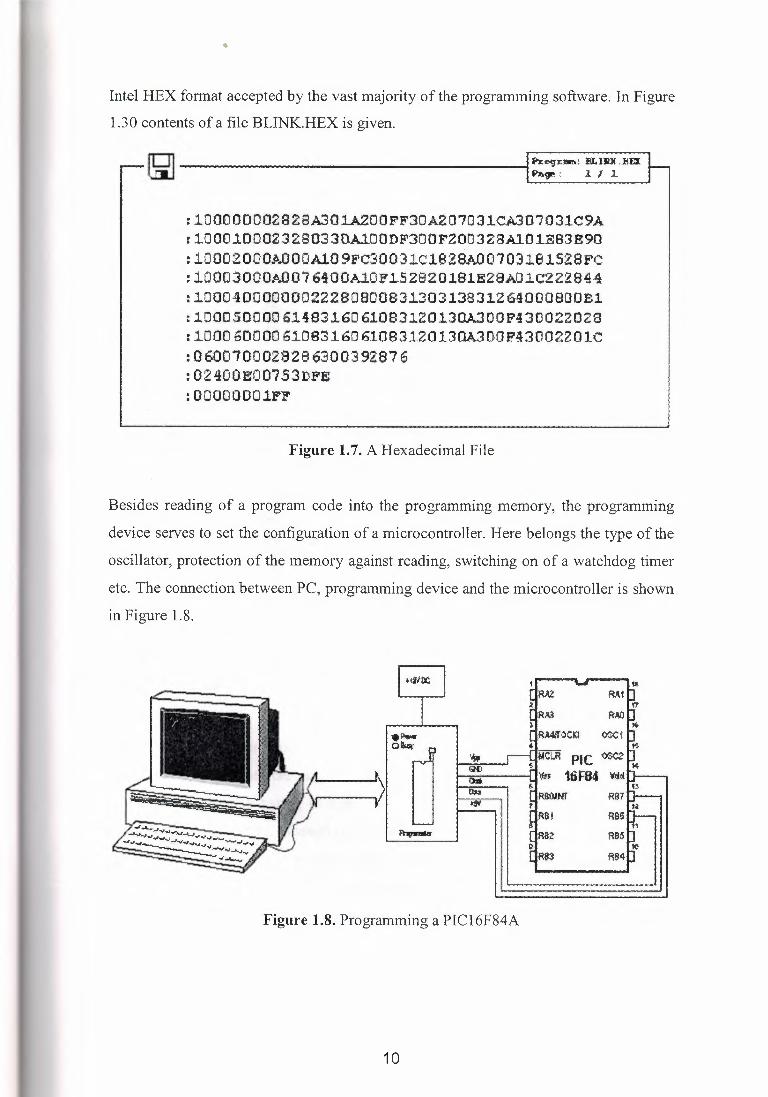
Intel HEX format accepted by the vast majority of the programming software. In Figure
1.30 contents of a file BLINK.HEX is given.
ID] h:~l!lffi: IU..IlllLI!CK lJiJ hl.9"!' ! 1 I 1
:10000000282SA301A.200FF30A207031CA307031C9A : 1000.100023ZS0330A.100DF300F200328il0l..EB3E90 : 10002000J..OOOA10 9FC300J1c1828>.0·0103191S28FC : 10003000J..007640·0Al0Fl.52620l9lE28AOlC2229!4 : 1.00040000000222BCl80083l.30313831.264000800B1 : 1000.50000 61483160 6l0B3120130A300F43002Z028 : 1000 60000 6108316061083120130A300F43002201C : 0600700028286300392876 :02400E00753DFE :00000001!'!'
Figure 1.7. A Hexadecimal File
Besides reading of a program code into the programming memory, the programming
device serves to set the configuration of a microcontroller. Here belongs the type of the
oscillator, protection of the memory against reading, switching on of a watchdog timer
etc. The connection between PC, programming device and the microcontroller is shown
in Figure 1.8.
>!flit; ~ ' ·--• RM
RAI)
.11,w,w I IR:AA.'fOCll ¢X1
110040 r RB7 •Sil
. ~!H RBS
~ RB2 RBS
Figure 1.8. Programming a PIC16F84A
10
•
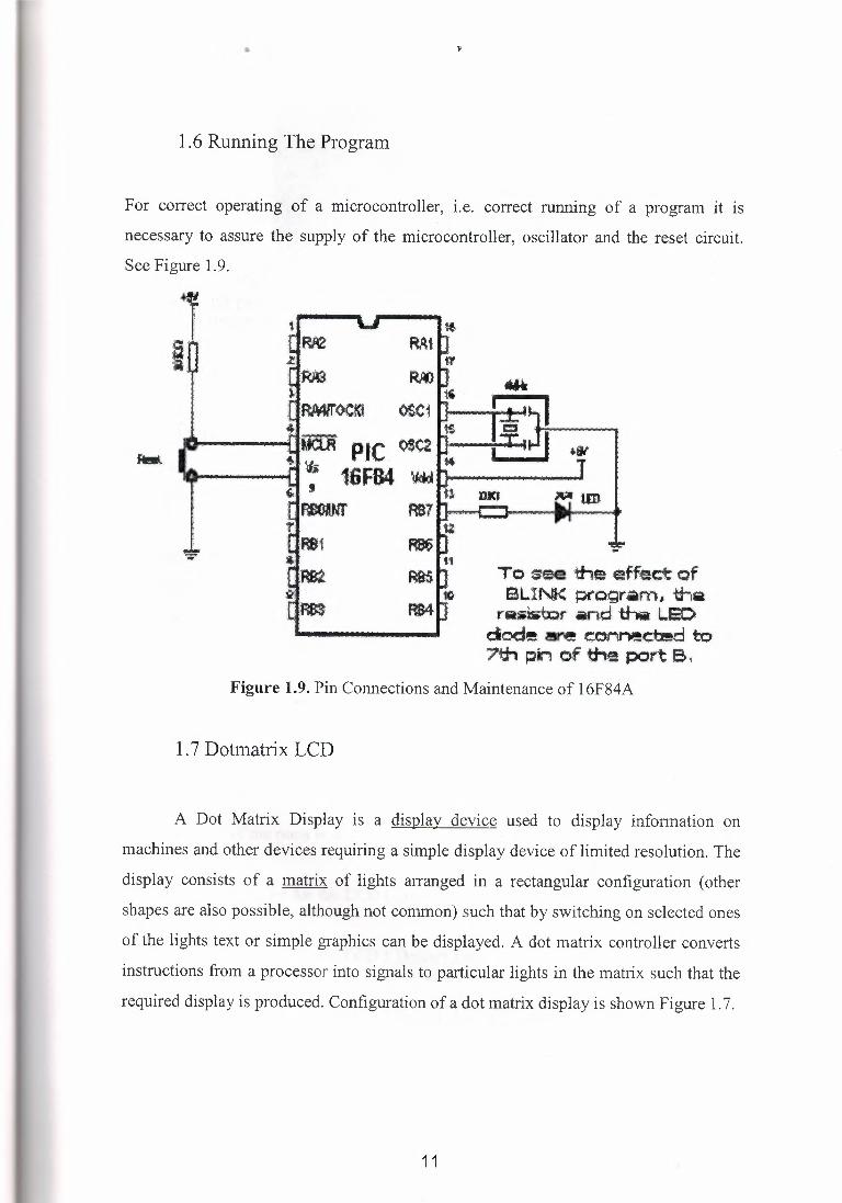
1.6 Running The Program
For correct operating of a microcontroller, i.e. correct running of a program it is
necessary to assure the supply of the microcontroller, oscillator and the reset circuit.
See Figure 1.9.
PIC <>e<2 16FB4 'IAti•
m1· t-c::J---~~ ti
flltJ .
RBS -~-
Mi
·Rll)
OOC1
To Scee the effect of BLihlK ;:;rogr.m, thia
ra.bib:::.lr -rtd tha t..lit:> dode ere e0Mr'1ed::ed to 7t.h pin of ti-te port e ..
Figure 1.9. Pin Connections and Maintenance of 16F84A
1. 7 Dotmatrix LCD
A Dot Matrix Display is a display device used to display information on
machines and other devices requiring a simple display device of limited resolution. The
display consists of a matrix of lights arranged in a rectangular configuration ( other
shapes are also possible, although not common) such that by switching on selected ones
of the lights text or simple graphics can be displayed. A dot matrix controller converts
instructions from a processor into signals to particular lights in the matrix such that the
required display is produced. Configuration of a dot matrix display is shown Figure 1. 7.
11
•
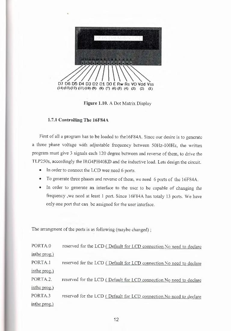
07 D6 D5 D4 03 02 01 DO E Rw Rs VO Vdd Vss (14)(13)(12) (11)(10) (9) (8) (7) (6) (5) (4) ('3) (2) (I)
Figure 1.10. A Dot Matrix Display
1.7.1 Controlling The 16F84A
First of all a program has to be loaded to thel 6F84A. Since our desire is to generate
a three phase voltage with adjustable frequency between 50Hz-100Hz, the written
program must give 3 signals each 120 degree between and reverse of them, to drive the
TLP250s, accordingly the IRG4PH40KD and the inductive load. Lets design the circuit.
• In order to connect the LCD wee need 6 ports.
• To generate three phases and reverse of them, we need 6 ports of the 16F84A.
• In order to generate an interface to the user to be capable of changing the
frequency , we need at least 1 port. Since 16F84A has totaly 13 ports. We have
only one port that can be assigned for the user interface.
The arrangment of the ports is as following (maybe changed) ;
PORTA.O reserved for the LCD ( Default for LCD connection.No need to declare inthe prog.)
PORTA.I reserved for the LCD ( Default for LCD connection.No need to declare inthe prog.)
PORTA.2. reserved for the LCD ( Default for LCD connection.No need to declare inthe prog.)
PORTA.3 reserved for the LCD ( Default for LCD connection.No need to declare inthe prog.)
12
PORTA.4 reserved for the LCD ( Default for LCD connection.No need to declare
inthe prog.)
PORTB.3 reserved for the LCD ( Default for LCD connection.No need to declare
inthe prog.)
PORTB.O 1. phase
PORTB.l 1. phase inverse
POR TB.2 2. phase
PORTB.4 2. phase inverse
PORTB.5 3. phase
PORTB.6 3. phase mverse
PORTB.7 Assigned for the user interface(changing the frequency)
2. MICRO COD STUDIO
2.1 General Explanation
We have much more diffrent program for program and control the pie.Assembly
language is so complex because of this many students didnt learn to program
microcontrollers.This nice program help us to program.Our language is Pie Basic pro to
use micro code studio.This program have a easy control firs write the program with use
pie basic code then compile the program.it is enough to work.This program change the
pie basic codde to hex code.Then I use to install this code to my pic.ic prog program.
Be attention to install the program,dont forget to put pbp240full doc. in your pc. Becase
This program can not work before to see pbp 240full doc. in your pc.
2.1.1 File Menu
• New - Creates a new document. A header is automatically generated, showing
information such as author, copyright and date. To toggle this feature on or off,
or edit the header properties, you should select editor options. When a new
document is created, the default target processor device is set to the 16F877. To
change the default, edit the file 'default.ini', located in your main installation
folder. You need to restart MicroCode Studio after making the changes.
13
• Open - Displays a open dialog box, enabling you to load a document into the
MicroCode Studio IDE. If the document is already open, then the document is
made the active editor page.
• Save - Saves a document to disk. This button is normally disabled unless the
document has been changed. If the document is 'untitled', a save as dialog is
invoked. A save as dialog is also invoked if the document you are trying to save
is marked as read only.
• Save As - Displays a save as dialog, enabling you to name and save a document
to disk.
• Close - Closes the currently active document
• Close All - Closes all editor documents and then creates a new editor document.
• Reopen - Displays a list of Most Recently Used (MRU) documents.
• Print Setup - Displays a print setup dialog.
• Print Preview - Displays a print preview window.
• Print - Prints the currently active editor page.
• Exit - Enables you to exit MicroCode Studio
2.1.2 View Menu
• Code Explorer - Display or hide the code explorer window.
• Serial Communicator - Displays the Serial Communicator software. For more
information, see the online help supplied with Serial Communicator.
• Loader - Displays the MicroCode Loader application. This option is only
available with MicroCode Studio Plus.
• Loader Options - Displays the Microcode Loader options dialog. This option is
only available with MicroCode Studio Plus.
• Toolbars - Display or hide the main, edit, compile and program and ICD
toolbars.
• Compile and Program Options - Displays the Compile and Program Options
dialog.
• Editor Options - Displays the main editor options dialog.
• Toolbars - Changes toolbar icon size and colors.
• Online Updates - Checks for online updates.
14
2.1.3 Project Menu
• Compile - Selecting this option will compile the currently active editor page.
• Compile and Program - Selecting this option will compile the currently active
editor page and then automatically start your chosen programmer.
• Program - Automatically start your chosen programmer.
• ICD Compile - Selecting this option will compile the currently active editor
page with debugging information.
• ICD Compile and Program - Selecting this option will compile the currently
active editor page with debugging information and then automatically start your
chosen programmer.
3. PIC BASIC PRO PROGRAMMING
3 .1 Information about Pie BasicPro
3.1.1. Introduction
The PicBasic Pro Compiler (or PBP) is our next-generation programmmg
language that makes it even quicker and easier for you to program Microchip
Technology's powerful PICmicro microcontrollers (MCUs). The English-like BASIC
language is much easier to read and write than the quirky Microchip assembly language.
The PicBasic Pro Compiler is "BASIC Stamp II like" and has most of the libraries and
functions of both the BASIC Stamp I and II. Being a true compiler, programs execute
much faster and may be longer than their Stamp equivalents.PBP is not quite as
compatible with the BASIC Stamps as our original PicBasic Compiler is with the BS 1.
Decisions were made that we hope improve the language overall. One of these was to
add a real IF .. THEN .. ELSE .. ENDIF instead of the IF .. THEN(GOTO) of the Stamps.
These differences are spelled out later in this manual. PBP defaults to create files that
run on a PIC16F84-04/P clocked at 4MHz. Only a minimum of other parts are
necessary: 2 22pf capacitors for the 4MHz crystal, a 4.7K pull-up resistor tied to the
/MCLR pin and a suitable 5- volt power supply. Many PICmicro MCUs other than the
16F84, as well as oscillators of frequencies other than 4MHz, may be used with the
PicBasic Pro Compiler.
15

3.1.1.1. The PICmicro MCUs
The PicBasic Pro Compiler produces code that may be programmed into a wide
variety of PICmicro microcontrollers having from 8 to 84 pins and various on-chip
features including AID converters, hardware timers and serial ports. The current version
of the PicBasic Pro Compiler supports all the Microchip Technology PICmicro MCUs,
including the 12-bit core, 14-bit core and both 16-bit core series, the 17Cxxx and
18Cxxx devices, as well as the Micromint PicStics. Limited support has been added for
PICmicro MCUs based on the original 12-bit core. Support is limited as the 12-bit core
PICmicro MCUs have a limited set of resources including a smaller stack and smaller
code page size. See the READ.ME file for the very latest PICmicro MCU support list.
For general purpose PICmicro MCU development using the PicBasic Pro Compiler, the
PIC16F628, 16F84, 16F876 and 16F877 are the current PICmicro MCUs of choice.
These microcontrollers use flash technology to allow rapid erasing and reprogramming
to speed program debugging. With the click of the mouse in the programming software,
the flash PICmicro MCU can be instantly erased and then reprogrammed again and
again. Other PICmicro MCUs in the 12C5xx, 12C67x, 14COOO, 16C4xx, 16C5x,
16C55x, 16C6xx, 16C7xx, 16C9xx, 17Cxxx and 18Cxxx series are either one-time
programmable (OTP) or have a quartz window in the top (JW) to allow erasure by
exposure to ultraviolet light for several minutes.
The PIC16F628, 16F84 and 16F87x devices also contain between 64 and 256 bytes of
non-volatile data memory that can be used to store program data and other parameters
even when the power is turned off.
This data area can be accessed simply by using the PicBasic Pro Compiler's READ and
WRITE commands. (Program code is always permanently stored in the PICmicro
MCU's code space whether the power is on or off.) By using a flash PICmicro MCU for
initial program testing, the debugging process may be sped along. Once the main
routines of a program are operating satisfactorily, a PICmicro MCU with more
capabilities or expanded features of the compiler may be utilized. While many
PICmicro MCU features will be discussed in this manual, for full PICmicro MCU
information it is necessary to obtain the appropriate PICmicro MCU data sheets or the
CD-ROM from Microchip Technology. Refer to Appendix F for contact information.
16
3.1.1.2. About This Manual
This manual cannot be a full treatise on the BASIC language. It describes the
PicBasic Pro Compiler instruction set and provides examples on how to use it. If you
are not familiar with BASIC programming, you should acquire a book on the topic. Or
just jump right in. BASIC is designed as an easy-to-use language. Try a few simple
commands to see how they work. Or start with the examples and then build on them.
The next section of this manual covers installing the PicBasic Pro Compiler and writing
your first program. Following is a section that describes different options for compiling
programs. Programming basics are covered next, followed by a reference section listing
each PicBasic Pro command in detail. The reference section shows each command
prototype, a description of the command and some examples. Curly brackets, {},
indicate optional parameters.
The remainder of the manual provides information for advanced programmers - the
inner workings of the compiler.
3.1.1.3. Sample Programs
Example programs to help get you started can be found in the SAMPLES
subdirectory. Additional example programs can be found in the sample programs
section.
EXAMPLE 1:
' PicBasic Pro program to demonstrate the Div32 command.
' Div32 must be used immediately after a multiply statement
' in order to retain the state of the internal registers of
' the device.
' Define Debug pin
DEFINE DEBUG REG PORTC
DEFINE DEBUG BIT 6
DEFINE DEBUG BAUD 9600
17
DEFINE DEBUG MODE 1
' Define variables for testing the command
WRESULT VAR WORD ' Used to store results to a word
EXPECTED VAR WORD 'Used to display the expected result
BRESULT VAR BYTE' Used to store results to a byte
bogus VAR BYTE 'Used to store intermediate results of the multiply
BBO VAR BYTE ' Data in byte form
BB 1 VAR BYTE ' Data in byte form
WWO VAR WORD ' Data in word form
WWI VAR WORD ' Data in word form
' Set values for testing
BB0=25
BB1=250
WW0=255
WW1=10052
Debug 10,13 ' Send new line
bogus= WWO * WWI
value
WRESULT = Div32 BB 1 'Divide 32-bit value by byte and store in word
EXPECTED = 10253 ' Expected result for this calculation
' Multiply to load internal registers with 32-bit
GoSub resultword ' Send the result with Debug
bogus= WWO * WWl ' Multiply to load internal registers with 32-bit
value
WRESULT = Div32 WWO
EXPECTED= 10052
GoSub resultword
' Divide 32-bit value by word and store in word
'Expected result for this calculation
'Send the result with Debug
18
•
bogus = WWO * WWI
value
WRESULT = Div32 1000
EXPECTED = 2563
GoSub resultword
bogus = BBO * BB 1 BRESULT = Div32 BBO
EXPECTED = 250
GoSub resultbyte
bogus = BBO * BB 1 BRESULT = Div32 WWO
EXPECTED = 24
GoSub resultbyte
bogus = BBO * BB 1 BRESULT = Div32 100
EXPECTED = 62
GoSub resultbyte
Debug 10,13
End
resultbyte:
' Multiply to load internal registers with 32-bit
'Divide 32-bit value by contant and store in word
' Expected result for this calculation
' Send the result with Debug
' Multiply to load internal registers with 32-bit value
' Divide 32-bit value by byte and store in byte
'Expected result for this calculation
' Send the result with Debug
' Multiply to load internal registers with 32-bit value
'Divide 32-bit value by word and store in byte
' Expected result for this calculation
' Send the result with Debug
'Multiply to load internal registers with 32-bit value
'Divide 32-bit value by contant and store in byte
' Expected result for this calculation
' Send the result with Debug
' Send new line
• Stop
' Send byte value
Debug "Byte Result= ",#BRESULT," ",#EXPECTED," Expected",10,13 Pause 500
Return
19
••
resultword: ' Send word value
Debug "Word Result= ",#WRESULT," ",#EXPECTED," Expected",10,13
Pause 500
Return
EXAMPLE 2:
' EEPROM, READ and WRITE Commands'
'Demonstate commands for EEPROM. Works on PIC16F(C)84 targets only!!!
' Initialized address 0 .. 5 and 9. Writes 10 .. 63. This leaves addesses
'6 .. 8 undefined (assuming your programmer doesn't unconditionally
'program all EEPROM locations).
Include "modedefs.bas"
so con 0
BO var byte
Bl var byte
B2 var byte
' Include serial modes
' Define serial output pin
EEPROM ["vwxyz"]
EEPROM 9,[100]
'EEPROM[0 . .4] = 118 . .122
' EEPROM[9] = 100
loop: BO= 63 ' Set Size of EEPROM
For Bl= lOTo BO
B2 =Bl+ 100
Write Bl,B2
Next Bl
' Check WRITE Command
'EEPROM[l0 .. 63] = 110 .. 163
ForBl=OToBO ' Check READ Command
20
Read B 1,B2 ' Dump EEPROM Contents
Serout SO,N2400,[#B2," "]
Next Bl
Serout SO,N2400,[ 10, 1 OJ ' Skip 2 Lines
Goto loop 'Forever
4. IC-PROG PROGRAMMIG
4.1 General Explanation
In this program we have a hex cod from the MicroCod studio.We open this
code from the Ic-prog program for install the pie.This is also be easy program but we
should attention some part of the program for work.we have some error because of this
program can not be work easly.When you seee like this kind of errors you should
control all of the set up agin.Dont wory for do same thing when you are correct the set
up because many times I see that if change and do same set up program can work and get well.
4.1.1 Set Up The Language
If the language is not Turkish you can change the language.Setting/Options/Language
After that we come to in side of Language set up
21

••
3FFF 3FFF 3FFF yyyyyyrjy 0010: 3FFF 3FFF 3FFF 3FFF YYYYmY. 0018: 3FFF 3FFF 3FFF 3FFF yyyyyyrjy 0020: 3FFF 3FFF 3FFF 3FFF yyyyyyrjy 0028: 3FFF 3FFF 3FFF 3FFF 3FFF 3FFF 3FFF 3FFF yyyyyyrjy 0030: 3FFF 3FFF 3FFF 3FFF 3FFF 3FFF 3FFF 3FFF YYYYmY. 0038: 3FFF 3FFF 3FFF 3FFF 3FFF 3FFF 3FFF 3FFF yyyyyyrjy 0040: 3FFF 3FFF 3FFF 3FFF 3FFF 3FFF 3FFF 3FFF yyyyyyrjy 0048.: 3FFF 3FFF 3FFF 3FFF 3FFF 3FFF 3FFF 3FFF yyyyyyrjy
3FFF 3FFF 3FFF 3FFF 3FFF 3FFF 3FFF 3FFF YYYYmY.
0008: FF FF FF FF FF FF FF FF 0010: FF FF FF FF FF FF FF FF ~ 0018: FF FF FF FF FF FF FF FF ~ 0020: FF FF FF FF FF FF FF FF ~ 0028: FF FF FF FF FF FF FF FF ~ 0030: FF FF FF FF FF FF FF FF ~
Figure 4.1. le prog set up
22
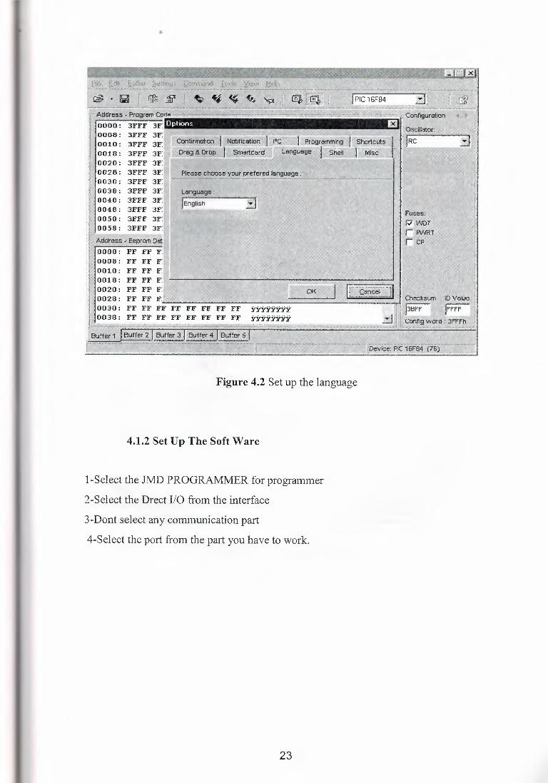
Figure 4.2 Set up the language
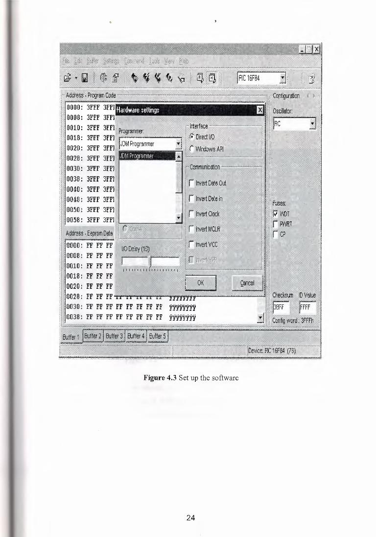
4.1.2 Set Up The Soft Ware
I-Select the JMD PROGRAMMER for programmer
2-Select the Drect I/0 from the interface
3-Dont select any communication part
4-Select the port from the part you have to work.
23
0028: 3FFF 3FFI 0030: 3FFF 3FFI 0038: 3FFF 3FFI 0040: 3FFF 3FFI 0048: 3FFF 3FFI 0050: 3FFF 3FFI
Figure 4.3 Set up the software
24
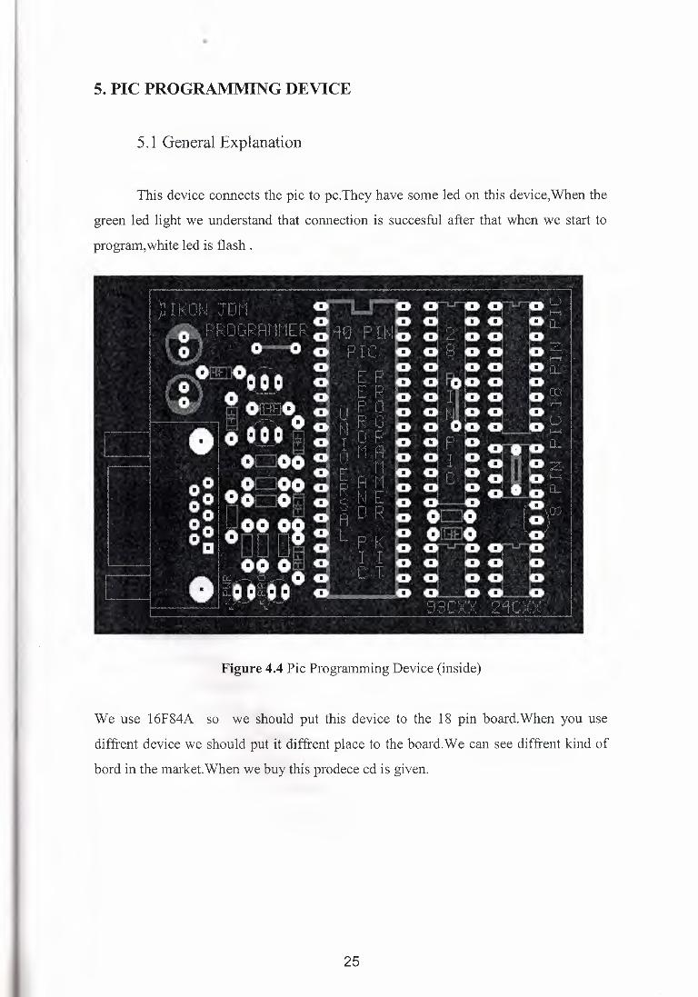
5. PIC PROGRAMMING DEVICE
5 .1 General Explanation
This device connects the pie to pc.They have some led on this device,When the
green led light we understand that connection is succesful after that when we start to
program,white led is flash .
Figure 4.4 Pie Programming Device (inside)
We use 16F84A so we should put this device to the 18 pin board.When you use
diffrent device we should put it diffrent place to the board.We can see diffrent kind of
bord in the market.When we buy this prodece cd is given.
25
••
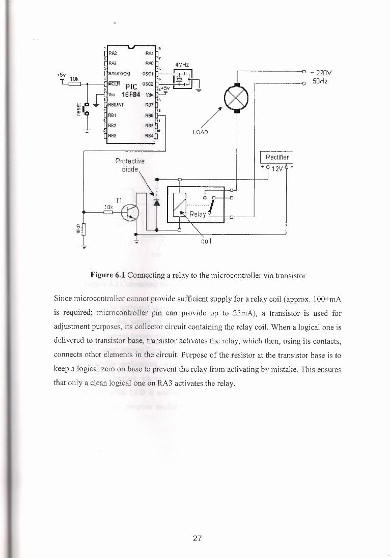
6. BACKGROUNG OF MYPROJECT
In this project I control the role by my pie.I give some comand which include
time relation to work the system.Roles trigger the contactor in the wall panel then the
motor is starting to work.
6.1 Relay
6.1.1 The Using Of Relay in My Project
My roles have double contact so that I wire the led and motor wire both part of
the role because of this they work at the same time. Then I can see motor working
easly while the connection cannot connect the motor.
If I cannot use role the system cannot be worked. because when I give a command to
my role .rt is only use my command.it means It can use my command to trigger the 5v
which is given out side of the role inside of the role.
6.1.2 Example Of Relay
I want to give interesting example to understand the principles of relay and on
the other side you will understant my Project easily.
The relay is an electromechanical device, which transforms an electrical signal into
mechanical movement. It consists of a coil of insulated wire on a metal core, and a
metal armature with one or more contacts. When a supply voltage was delivered to the
coil, current would flow and a magnetic field would be produced that moves the
armature to close one set of contacts and/or open another set. When power is removed
from the relay, the magnetic flux in the coil collapses and produces a fairly high voltage
in the opposite direction. This voltage can damage the driver transistor and thus a
reverse-biased diode is connected across the coil to "short-out" the spike when it occurs.
26
+Sv
RP2 RA1
RA.3 R,QJJ ~ 4MHz 1&
RA41rOCKI 0. SC. 1. . i: 1 '3 I i ~
1S = ~ p IC QSC2 ~ T I
14+::iv - Vs.s 16F84 Vaci - -
RBO~NT R87
RB1 RB6
RB2 RB5
RB3 RB4
Protective diode\
~
coil
+
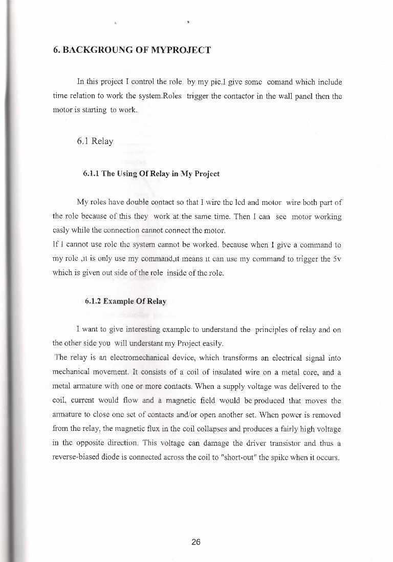
Figure 6.1 Connecting a relay to the microcontroller via transistor
- 220V 50Hz
Since microcontroller cannot provide sufficient supply for a relay coil ( approx. 1 OO+mA
is required; microcontroller pin can provide up to 25mA), a transistor is used for
adjustment purposes, its collector circuit containing the relay coil. When a logical one is
delivered to transistor base, transistor activates the relay, which then, using its contacts,
connects other elements in the circuit. Purpose of the resistor at the transistor base is to
keep a logical zero on base to prevent the relay from activating by mistake. This ensures
that only a clean logical one on RA3 activates the relay.
27
••
RBO~NT
RB1
RB2
R88
RB7
RB6
RA2 RA1
// ,'
LOAD
-220V 50Hz
+Sv
Protectiv·e .. ·. . J.. 11 Rectifier 11 d,ode\ . + j 12l ~J I l 1 I
Optocoupler supply Relay
H11 B1
/ coil
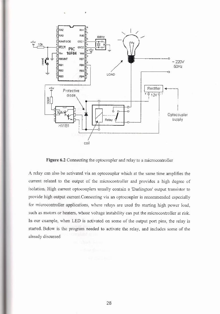
Figure 6.2 Connecting the optocoupler and relay to a microcontroller
A relay can also be activated via an optocoupler which at the same time amplifies the
current related to the output of the microcontroller and provides a high degree of
isolation. High current optocouplers usually contain a 'Darlington' output transistor to
provide high output current.Connecting via an optocoupler is recommended especially
for microcontroller applications, where relays are used fro starting high power load,
such as motors or heaters, whose voltage instability can put the microcontroller at risk.
In our example, when LED is activated on some of the output port pins, the relay is
started. Below is the program needed to activate the relay, and includes some of the
already discussed
28
"
LOGIC: [1) HIGH TO BASE, CJF TJ .. ANSl:STOR ENERCHZES REL.A'>/
~ ~ oso
DUPUCA TE nus G.-1RCtHT FC)REAC'.H LOAD t'C)U WISH TO GONTR!JL THE.H CCJ.NNECT TO OUTPUTS 1-12 ON THE. ?1C16F84
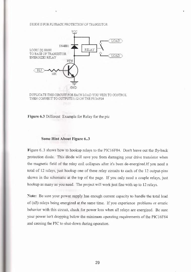
Figure 6.3 Different Example for Relay for the pie
Some Hint About Figure 6 •• 3
Figure 6 .. 3 shows how to hookup relays to the PIC16F84. Don't leave out the fly-back
protection diode. This diode will save you from damaging your drive transistor when
the magnetic field of the relay coil collapses after it's been de-energized.If you need a
total of 12 relays, just hookup one of these relay circuits to each of the 12 output-pins
shown in the schematic at the top of the page. If you only need a couple relays, just
hookup as many as you need. The project will work just fine with up to 12 relays.
Note: Be sure your power supply has enough current capacity to handle the total load
of (all) relays being energized at the same time. If you experience problems or erratic
behavior with this circuit, check for power loss when all relays are energized. Be sure
your power isn't dropping below the minimum operating requirements of the PIC16F84
and causing the PIC to shut-down during operation.
29
6.2 Transistor
In my system if I cannot use transistor,my project can work,but Transistor give a
determination to the system .When I search for my project then I see that most of the
projects use transistor if they want to use a role and they connect the transistor before
the role.I use BC237 transistor ,this transistor has NPN structure.
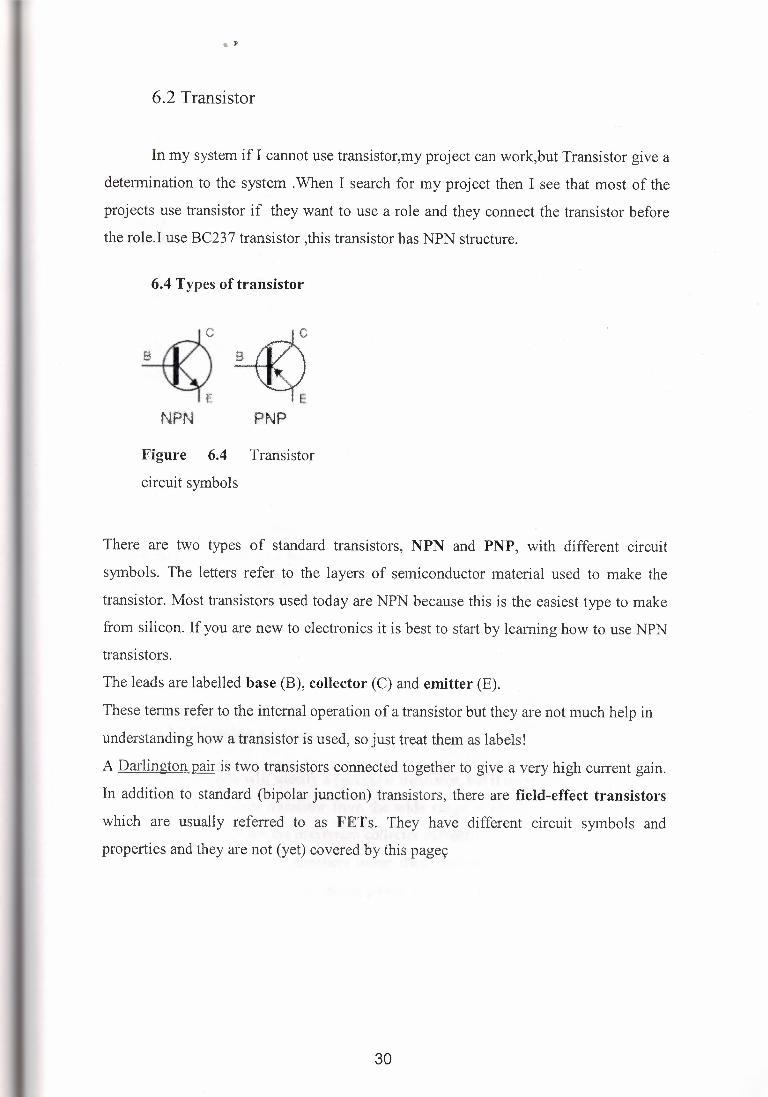
6.4 Types of transistor
NPN PNP
Figure 6.4 Transistor
circuit symbols
There are two types of standard transistors, NPN and PNP, with different circuit
symbols. The letters refer to the layers of semiconductor material used to make the
transistor. Most transistors used today are NPN because this is the easiest type to make
from silicon. If you are new to electronics it is best to start by learning how to use NPN
transistors.
The leads are labelled base (B), collector (C) and emitter (E).
These terms refer to the internal operation of a transistor but they are not much help in
understanding how a transistor is used, so just treat them as labels!
A Darlington pair is two transistors connected together to give a very high current gain.
In addition to standard (bipolar junction) transistors, there are field-effect transistors
which are usually referred to as FETs. They have different circuit symbols and
properties and they are not (yet) covered by this pagec
30
8 EOC TO't8 T039
I * w I i I BCE T0218 T0220
•
EC B
~
E .B C
~
C B E
~·
T092A T092B T092C Views. are 1:rorn oolow with the reads tclwarcts yow ..
0
C ls the meta! ease itself T03
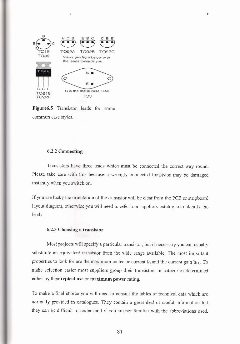
Figure6.5 Transistor leads for some
common case styles.
6.2.2 Connecting
Transistors have three leads which must be connected the correct way round.
Please take care with this because a wrongly connected transistor may be damaged
instantly when you switch on.
If you are lucky the orientation of the transistor will be clear from the PCB or stripboard
layout diagram, otherwise you will need to refer to a supplier's catalogue to identify the leads.
6.2.3 Choosing a transistor
Most projects will specify a particular transistor, but if necessary you can usually
substitute an equivalent transistor from the wide range available. The most important
properties to look for are the maximum collector current le and the current gain hFE· To
make selection easier most suppliers group their transistors in categories determined
either by their typical use or maximum power rating.
To make a final choice you will need to consult the tables of technical data which are
normally provided in catalogues. They contain a great deal of useful information but
they can be difficult to understand if you are not familiar with the abbreviations used.
31
•
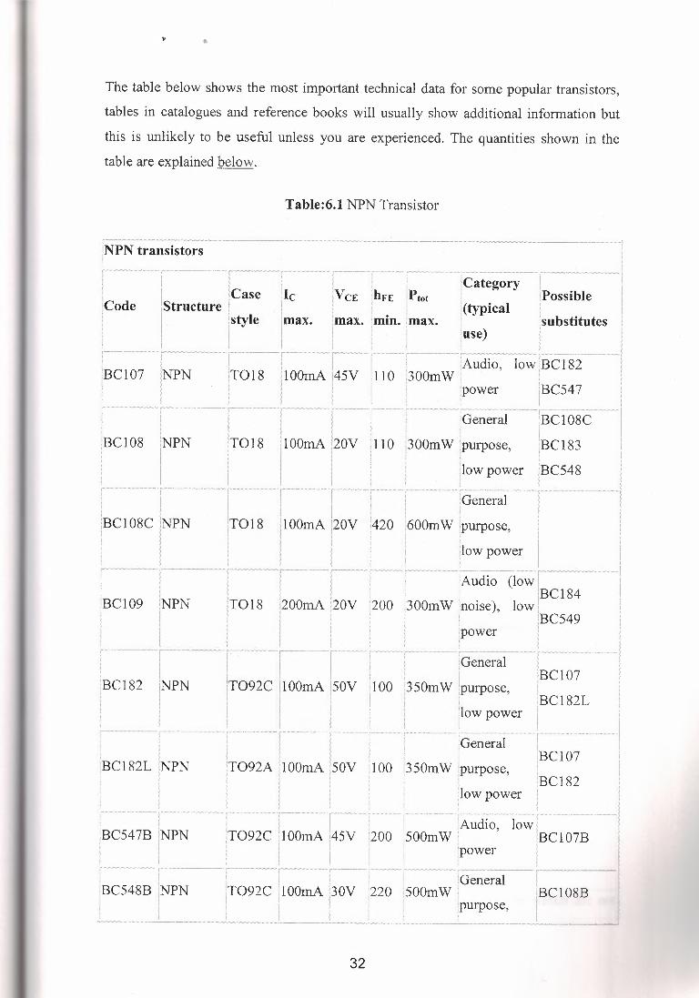
The table below shows the most important technical data for some popular transistors,
tables in catalogues and reference books will usually show additional information but
this is unlikely to be useful unless you are experienced. The quantities shown in the
table are explained below.
Table:6.1 NPN Transistor
N transistors r-- r ·-- i .. ····-, ··-·-·--. -····- ···-i ,
I I I I I !Category I . [Case lie 1V CE ,hFE ,Ptot : 1Poss1ble 1 [Structure I 1 · l · · :(typical j I
I . jstyle [max. [max. [min. ;max. : [substitutes I I I I I , [use) 1 l ' i I i i . I I
··················-·r ··-·- ·-1·-···r-· r-·· ... ,.........._L~~clio, 1;~lBcis2 .. ··1 IBC107 INPN IT018 1100mA.145V 110 '300mW I. · I
1
1 i I [power IBC54 7 I I I , . I 1
_.,.,,,,,-.,·,, ··-·,,·-· ·-·- ~- ;-....... - • .......• _,, •......•.. ,,--,I -,-,_,,, r··-·-·····-··-··-1 i i 1 [General IBC108C l
IOOmA l20v 1110 f300mw !purpose, IBCI83 I 'low power IBC548 i ! I . ;
1 T- r T-T . [General -1 - 1
iBC108C IINPN IT018 !lOOmA 120v :420 1600mW !purpose, I II ! I I l : 1 [low power I : ·--- ---,···-·---1..;'. ' -···,·-·····~--·········-- ! .,,, -·· . ·--1 I I I I ; [Audio (low I iBC109 INPN IT018 !2oomA '2ov [200.
1!300mW :.'noise), lowlBClS4
I 1 1 1 : , 1 BC549
' I I I I I i I I I , : : :power ' I ,--- ,1_,,,, [: ······-- .. -:-----······ .. -~... 1
I i i [General I I I I I I i 1BC 107 I
T092C 11oomA 1sov poo i350mW !purpose, I i . I i i l jBC l 82L 1 1 1 i · llow power I 'I ! I : · 1
Cl82L ~PN rT:92~co=~t~ !!Oo 1350mW:~:::, IBCIO? i I I I ! I ! : IBC 182 I i I 11 i [low power I
·.·~-·--···- .. ··.··········· ···-··;···-- ·,·· ·_ :_ ._i : . --·----! , , I I I , , [Audio, low, , iBC547B INPN iT092C !lOOmA J45V f200 :soomw: IBC107B ·
I I I I ! :power l 1 i _,,,,,., . ··-----,--·-r···-r --··, '":··- ····~··--··--r-·
!BC548B INPN IT092C llOOmA j3oV i220 !SOOmW iGeneral IBC108B I i I' 1 1 : rpurpose, I I I I , . i !
=m=-~-,,,,,=ow.,~,,-~~=-----··=·,w.--,~~~~~-m....-~w A,-~,~-~---,~·
!Code
;BC108 i l
NPN T018
i
! IBC182 NPN
32
•
r lnP31A I
ITIP41A [high power I 1 1
, General ---,-··· .. ·--- - I
purpose, I I
ighpower I C"''""''-""''"''"' ,,,,,,,,,,,,,,,,
I , I' :1, 1 [high power I I · .
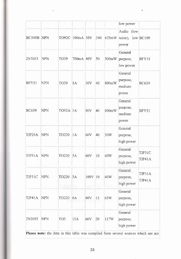
note: the data in this table was compiled from several sources which are not
IT092C IOOmA pov I , I I
iT039 · 11~:o:: l4ov I
1 I
240 tBC549B INPN ' l
i2N3053 PN
IA 30V
1"-1" ,,,, ! 1
I
180V :40 l
BC639 NPN
!TIP29A INPN
!TIP31A INPN I I I
iTIP31 C iNPN }
T0220 13A 60V !10
I ······ ··r ············· r I I IT0220 13A I - I I , ·· ·. ··· r --r ..-----,
: I ! iTIP41A INPN !T0220 ' . i
lOOV 110
6A 60V !15
!2N3055 INPN T03 15A 60V !20
33
power I ,"-""i"'"',"'"'--r,,.,,,,. .,,,,,,,_, I
' [Audio (low, I i i I 1 :625rn W !noise), low JBC 109 l
;power J '
'General ·················r
500m W [purpose, 1BFY 51
!low power I i
·,- ,,,,,,,,,_,,_,,,r- ,,,,,,,,,
!General I , ,purpose, 1
!800mW i IBC639 · !medium I
lpower I ' I ,
! ! , ,,, __ ,-,,,,,, ,.,, .,,,,,, ,,, ,,,, :General I l
.purpose, 1
800mW ! l'BFY51 imedium .
:power
how i ipurpose,
!high power
lGeneral
i40W IP31C
IP41A [purpose, !
jhigh power i General
!40W urpose,
:65W
117W purpose,
,,' \ ·,,,.,, '\ ••
:1~11ti;ely consistent! Most of the di;cr~pa~~ies are mino1:,·· b~t .p. lea;~ consult inforni~tio~ I I ~1 lfrorn your supplier if you require precise data. · ,j ? l
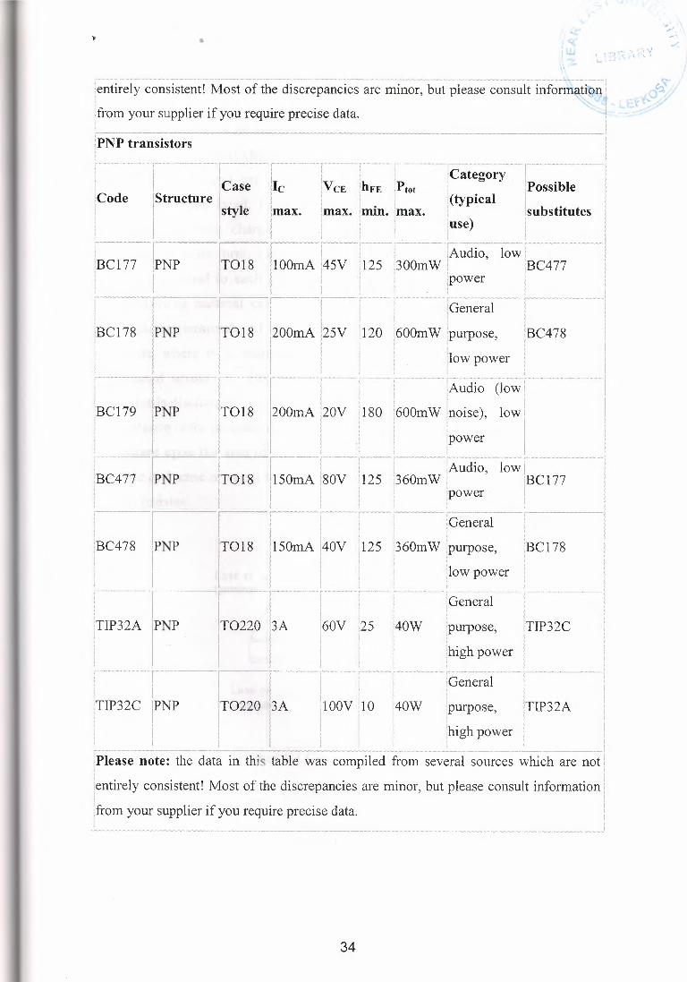
PNP transistors
lCode 'hFE !Ptot 'min. [max.
r [Category !Possible
, lsubstitutes I I I
i
j(typical
iuse)
r =,==A-ll,.•.'>-ll: V=llllA'll"---~f""'"-='llh~ll,~--~A-c--,!
· ! 1General I I ' . I I
120 i600mW :purpose, IBC478 ·1
I
i''"''-"''-i . I iBCl 78 !PNP
I IT018 I I
200mA 125V
[low power . . I
I
iAudio (low
180 600m W [noise), low ; [power
; : ' s • r-~ .· >,.WdAYHN~M>S> C .~~w.w,,=,nv= : -A , "~ O ·"·~,-.,.·NA~'-~"SS-MA' ~ ,v,;,~·.W, "-''"w,, .~,-=,=
I I [Audio, low I ll25 l360mW ! l'BCl 77
1power ·
r ··1
f ! l200mA l2ov I I I . I
!BCl 79 IPNP T018
iBC477 I IT018 l150mA l80V
I NP
I General '360m W [purpose,
I [low power !
. I fBC478 IPNP
I ...... I TIP32A IPNP I I ' I
I
!Bel 78 T018 150mA
. . T , . .. , . I I I ! lGeneral j
IT0220 13A !60V 25 !40W [purpose, !TIP32C ! I I . . I I l i thigh power I I I I I ... ·-r-··- .. -- .. ,.f.,...... ,........ , ., ..... I ! 1General 1
I I . I
T0220 '3A i40W :purpose, ITIP32A
! [high power I < :
·=,w.w,•.~w=-·,-·.·.·.· '.W.W
1=-.wll=Nm,•=,=m NN,·.Wwrno•v,;,w ,.,.·.•=,•,•~=M=m~o·.W.WA'AW.,VN ! ,._,_.,,,,,.v,=Aw==~-.!
[Please note: the data in this table was compiled from several sources which are not I l t lentirely consistent! Most of the discrepancies are minor, but please consult information! I I
!TIP32C ;
NP
[from your supplier if you require precise data. ;
34
••
6.3. Capacitors
A capacitor is an electrical storage component that has the capability of
accepting an electrical charge (voltage and current) from a voltage source. This
charge can be stored for as long as required and then released. The unit of
capacitance is the farad, F, named after Michael Faraday. By definition, a one
farad capacitor will charge to one volt in one second with a current of one
ampere.In its basic form, a capacitor consists of two conducting metal plates with
terminals attached to each plate. Sandwiched between the two metal plates is a
nonconducting material called the dielectric. By applying a voltage across the
metal plates (terminals) of the capacitor, an electric charge is applied across its
dielectric where it is stored until discharged. The polarity of the voltage is
maintained across the dielectric until the applied voltage is reversed or the
capacitor is discharged.
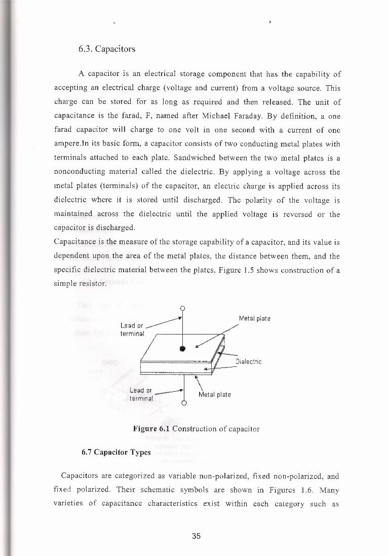
Capacitance is the measure of the storage capability of a capacitor, and its value is
dependent upon the area of the metal plates, the distance between them, and the
specific dielectric material between the plates. Figure 1.5 shows construction of a
simple resistor.
Lead or__.~ terminal
\ \ Metal plate
Le ad or _________.. terminal
Figure 6.1 Construction of capacitor
6. 7 Capacitor Types
Capacitors are categorized as variable non-polarized, fixed non-polarized, and
fixed polarized. Their schematic symbols are shown in Figures 1.6. Many
varieties of capacitance characteristics exist within each category such as
35
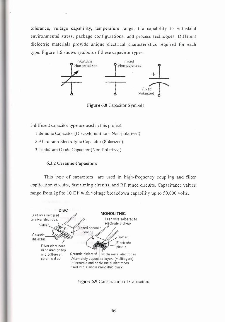
tolerance, voltage capability, temperature range, the capability to withstand
environmental stress, package configurations, and process techniques. Different
dielectric materials provide unique electrical characteristics required for each
type. Figure 1.6 shows symbols of these capacitor types.
I N9lixed ~poJariz•d
T Fixe~ P~lari~;d ! .
Figure 6.8 Capacitor Symbols
3 different capacitor type are used in this project.
1.Seramic Capacitor (Disc-Monolithic - Non-polarized)
2.Aluminum Electrolytic Capacitor (Polarized)
3.Tantalium Oxide Capacitor (Non-Polarized)
6.3.2 Ceramic Capacitors
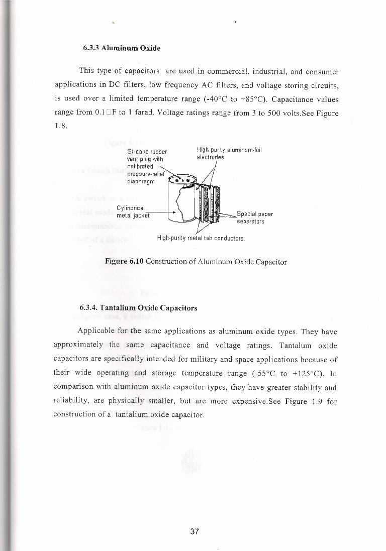
This type of capacitors are used in high-frequency coupling and filter
application circuits, fast timing circuits, and RF tuned circuits. Capacitance values
range from lpfto 10 DF with voltage breakdown capability up to 50,000 volts.
DISC
Ceramic dielectric I Noble metal electrodes Alternately deposited layers (multilayers) of ceramic and noble metal electrodes fired into a single monolithic block
Figure 6.9 Construction of Capacitors
36
6.3.3 Aluminum Oxide
This type of capacitors are used in commercial, industrial, and consumer
applications in DC filters, low frequency AC filters, and voltage storing circuits,
is used over a limited temperature range (-40°C to +85°C). Capacitance values
range from 0.1 OF to 1 farad. Voltage ratings range from 3 to 500 volts.See Figure 1.8.
Silicone rubber vent plug with calibrated ~ pressure.-relief ~.. ·. . . --- ..•. diaphragm ~ t 11
High purity aluminum-foil electrodes
Cylindrical ----+-+ metal jacket liHII g --- Special papar
separators
High-purity metal tab conductors
Figure 6.10 Construction of Aluminum Oxide Capacitor
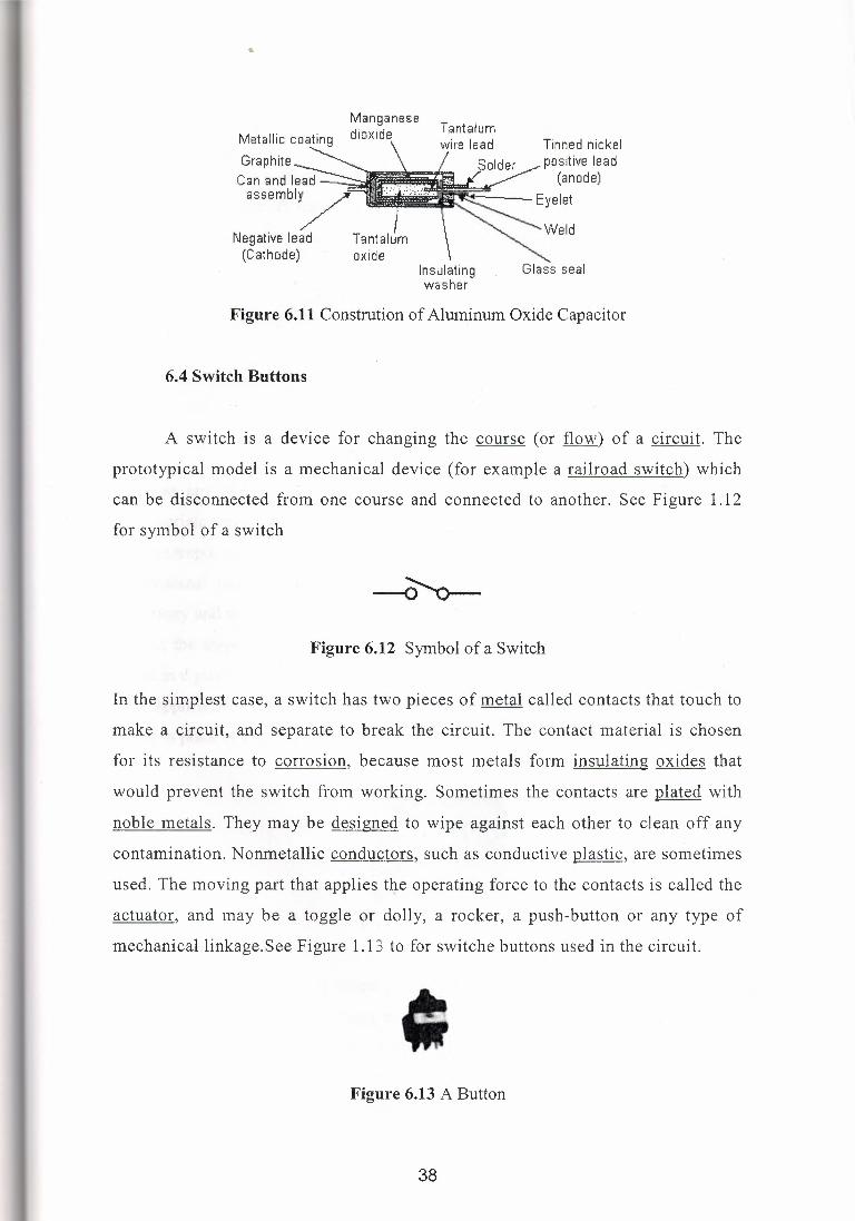
6.3.4. Tantalium Oxide Capacitors
Applicable for the same applications as aluminum oxide types. They have
approximately the same capacitance and voltage ratings. Tantalum oxide
capacitors are specifically intended for military and space applications because of
their wide operating and storage temperature range (-55°C to + 125°C). In
comparison with aluminum oxide capacitor types, they have greater stability and
reliability, are physically smaller, but are more expensive.See Figure 1.9 for
construction of a tantalium oxide capacitor.
37
••
Manganese Metallic coating dioxide
Graphite ~ "' Can and I~ assembly ,;:-
/ Negative lead Tantalum (Cathode) oxide
Tantalum Tinned nickel positive lead (anode)
---Eyelet
~------ ~'Veld
Glass seal Insulating washer
Figure 6.11 Constrution of Aluminum Oxide Capacitor
6.4 Switch Buttons
A switch is a device for changing the course ( or flow) of a circuit. The
prototypical model is a mechanical device (for example a railroad switch) which
can be disconnected from one course and connected to another. See Figure 1.12
for symbol of a switch
Figure 6.12 Symbol of a Switch
In the simplest case, a switch has two pieces of metal called contacts that touch to
make a circuit, and separate to break the circuit. The contact material is chosen
for its resistance to corrosion, because most metals form insulating oxides that
would prevent the switch from working. Sometimes the contacts are plated with
noble metals. They may be designed to wipe against each other to clean off any
contamination. Nonmetallic conductors, such as conductive plastic, are sometimes
used. The moving part that applies the operating force to the contacts is called the
actuator, and may be a toggle or dolly, a rocker, a push-button or any type of
mechanical linkage.See Figure 1.13 to for switche buttons used in the circuit.
• ' Figure 6.13 A Button
38
••
6.5 Crystals
A crystal is a solid in which the constituent atoms, molecules, or ions are packed
in a regularly ordered, repeating pattern extending in all three spatial dimensions.See
Figure 1.14 for symbol of a cyristal.and its equivalent circuit.
<>--l n r---<>
L1 R:t
Figure 6.14 Equivalent Circuit of Crystal
Almost any object made of an elastic material could be used like a crystal, with
appropriate transducers, since all objects have natural resonant frequencies of vibration.
For example, steel is very elastic and has a high speed of sound. It was often used in
mechanical filters before quartz. The resonant frequency depends on size, shape,
elasticity and the speed of sound in the material. High-frequency crystals are typically
cut in the shape of a simple, rectangular plate. Low-frequency crystals, such as those
used in digital watches, are typically cut in the shape of a tuning fork.
For applications not needing very precise timing, a low-cost ceramic resonator is often
used in place of a quartz crystal. See Figure 6.6
Figure 6.15 A Crystal
When a crystal of quaiiz is properly cut and mounted, it can be made to bend in an
electric field, by applying a voltage to an electrode near or on the crystal. This property
is known as piezoelectricity. When the field is removed, the quartz will generate an
electric field as it returns to its previous shape, and this can generate a voltage. The
result is that a quartz crystal behaves like a circuit composed of an inductor, capacitor
39
and resistor, with a precise resonant frequency. Quartz has the further advantage that its
size changes very little with temperature. Therefore, the resonant frequency of the plate,
which depends on its size, will not change much, either. This means that a quartz clock,
filter or oscillator will remain accurate. For critical applications the quartz oscillator is
mounted in a temperature-controlled container, called an crystal oven, and can also be
mounted on shock absorbers to prevent perturbation by external mechanical vibrations.
Quartz timing crystals are manufactured for frequencies from a few tens of kilohertz to
tens of megahertz. More than two billion (2 x I 09) crystals are manufactured annually.
Most are small devices for wristwatches, clocks, and electronic circuits. However,
quartz crystals are also found inside test and measurement equipment, such as counters,
signal generators, and oscilloscopes.
6.6. Resistors
A resistor is a standard component that provides resistance in an electrical
or electronic circuit. It is available as either a fixed resistor having a specific
value in ohms or as a variable resistor with an adjustable range of specified values.
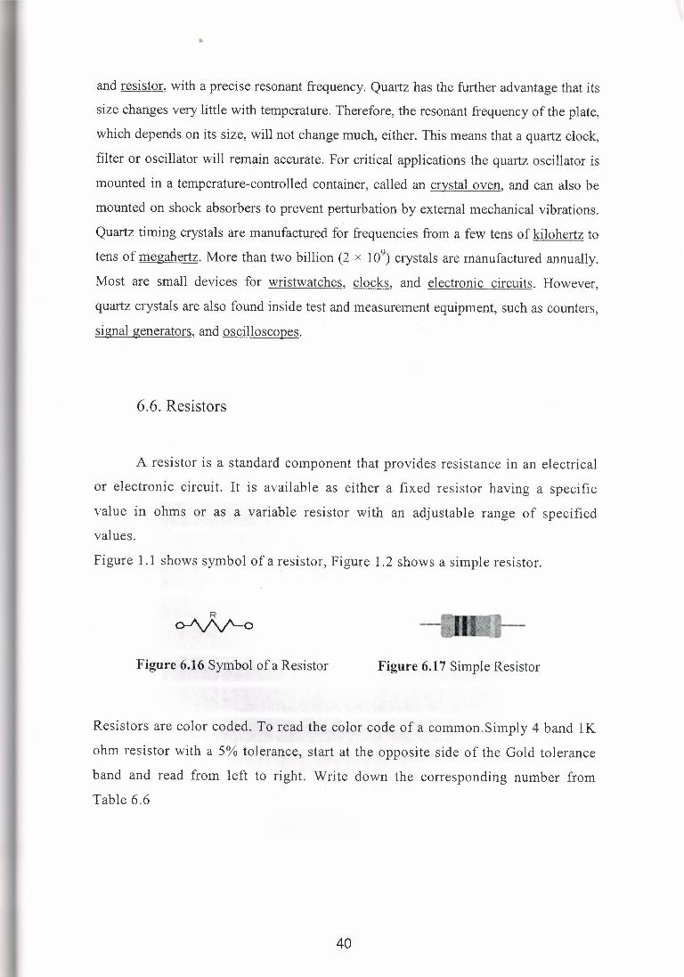
Figure 1.1 shows symbol of a resistor, Figure 1.2 shows a simple resistor.
R o-/\,/\/'-o
Figure 6.16 Symbol of a Resistor Figure 6.17 Simple Resistor
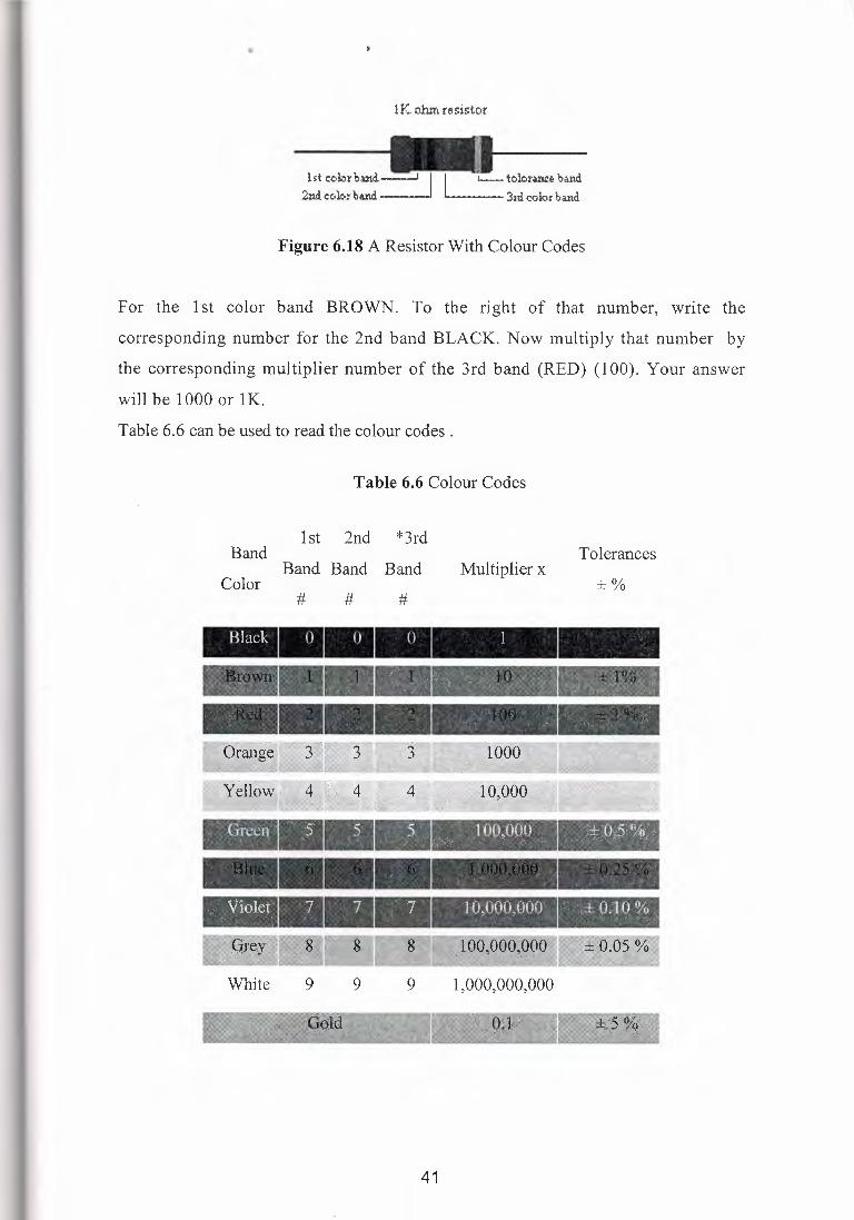
Resistors are color coded. To read the color code of a common.Simply 4 band lK
ohm resistor with a 5% tolerance, start at the opposite side of the Gold tolerance
band and read from left to right. Write down the corresponding number from
Table 6.6
40
••
1 K ohm resistor
.__ 3rd color band
Figure 6.18 A Resistor With Colour Codes
For the 1st color band BROWN. To the right of that number, write the·
corresponding number for the 2nd band BLACK. Now multiply that number by
the corresponding multiplier number of the 3rd band (RED) (100). Your answer
will be .1000 or 1 K.
Table 6.6 can be used to read the colour codes .
Table 6.6 Colour Codes
Band
Color
1st 2nd *3rd
Band Band Band Multiplier x Tolerances
±% # # #
White 9 9 9 1,000,000,000
41
•
6.7 AC motors
A typical A-C motor consists of two parts:
1. An outside stationary stator having coils supplied with AC current to produce a
rotating magnetic field, and;
2. An inside rotor attached to the output shaft that is given a torque by the rotating
field.
There are two fundamental types of AC motor depending on the type of rotor used:
• The synchronous motor, which rotates exactly at the supply frequency or a
submultiple of the supply frequency, and;
• The induction motor, which turns slightly slower, and typically (though not
necessarily always) takes the form of the squirrel cage motor.
The rotating magnetic field principle, though commonly credited to Nikola Tesla in
1882 or thereabouts, was employed by scientists such as Michael Faraday and James
Clerk Maxwell in the 1820s. Tesla, however, exploited the principle to design a unique
two-phase induction motor in 1883. Michael von Dolivo-Dobrowlsky invented the first
modem three-phase "cage-rotor" in 1890. Introduction of the motor from 1888 onwards
initiated what is known as the Second Industrial Revolution, making possible the
efficient generation and long distance distribution of electrical energy using the
alternating current transmission system, also of Tesla's invention (1888). The first
successful commercial three phase generation and long distance transmission system
was designed by Almerian Decker at Mill Creek No. in Redlands California.
42
•
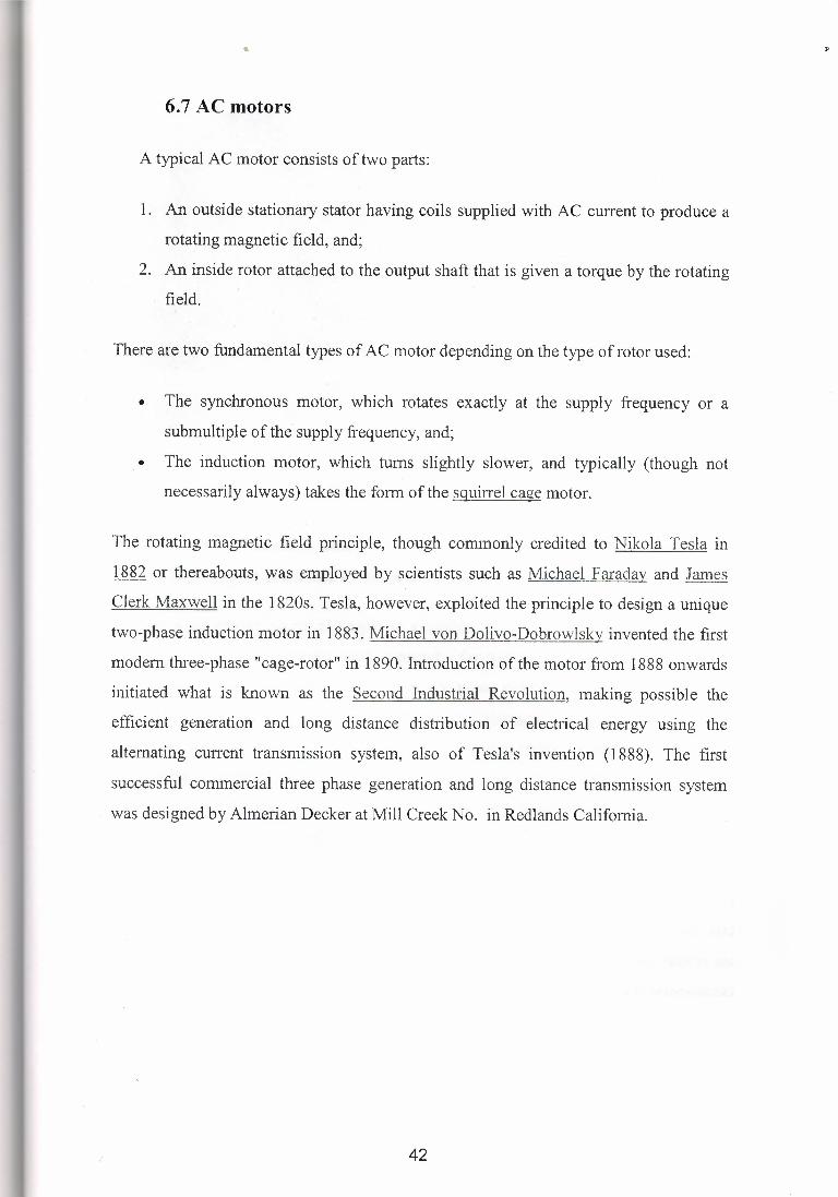
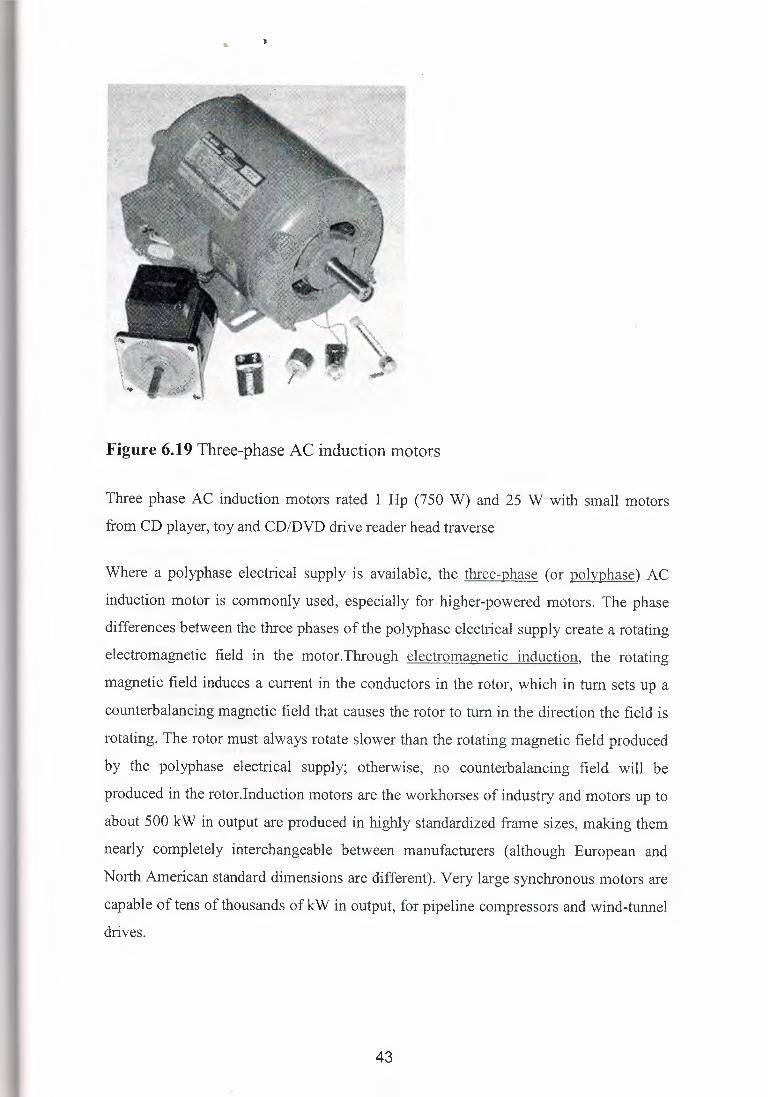
Figure 6.19 Three-phase AC induction motors
Three phase AC induction motors rated 1 Hp (750 W) and 25 W with small motors
from CD player, toy and CD/DVD drive reader head traverse
Where a polyphase electrical supply is available, the three-phase (or polvphase) AC
induction motor is commonly used, especially for higher-powered motors. The phase
differences between the three phases of the polyphase electrical supply create a rotating
electromagnetic field in the motor.Tlu·ough electromagnetic induction, the rotating
magnetic field induces a current in the conductors in the rotor, which in tum sets up a
counterbalancing magnetic field that causes the rotor to tum in the direction the field is
rotating. The rotor must always rotate slower than the rotating magnetic field produced
by the polyphase electrical supply; otherwise, no counterbalancing field will be
produced in the rotor.Induction motors are the workhorses of industry and motors up to
about 500 kW in output are produced in highly standardized frame sizes, making them
nearly completely interchangeable between manufacturers (although European and
North American standard dimensions are different). Very large synchronous motors are
capable of tens of thousands of kW in output, for pipeline compressors and wind-tunnel
drives.
43
••
There are two types of rotors used in induction motors.
Squirrel Cage rotors: Most common AC motors use the squirrel cage rotor, which will
be found in virtually all domestic and light industrial alternating current motors. The
squirrel cage takes its name from its shape - a ring at either end of the rotor, with bars.
connecting the rings running the length of the rotoL It is typically cast aluminum or
copper poured between the iron laminates of the rotor, and usually only the end rings
will be visible. The vast majority of the rotor currents will flow through the bars rather
than the higher-resistance and usually varnished laminates. Very low voltages at very
high currents are typical in the bars and end rings; high efficiency motors will often use
cast copper in order to reduce the resistance in the rotor.In operation, the squirrel cage
motor may be viewed as a transformer with a rotating secondary - when the rotor is not
rotating in sync with the magnetic field, large rotor currents are induced; the large rotor
currents magnetize the rotor and interact with the stator's magnetic fields to bring the
rotor into synchronization with the stator's field. An unloaded squirrel cage motor at
synchronous speed will only consume electrical power to maintain rotor speed against
friction and resistance losses; as the mechanical load increases, so will the electrical
load - the electrical load is inherently related to the mechanical load. This is similar to a
transformer, where the primary's electrical load is related to the secondary's electrical
load.This is why, as an example, a squirrel cage blower motor may cause the lights in a
home to dim as it starts, but doesn't dim the lights when its fanbelt ( and therefore
mechanical load) is removed. Furthermore, a stalled squirrel cage motor ( overloaded or
with a jammed shaft) will consume current limited only by circuit resistance as it
attempts to start. Unless something else limits the current (or cuts its off completely)
overheating and destruction of the winding insulation is the likely outcome.Virtually
every washing machine, dishwasher, standalone fan, record player, etc. uses some
variant of a squirrel cage motor.
Wound Rotor: An alternate design, called the wound rotor, is used when variable
speed is required. In this case, the rotor has the same number of poles as the stator and
the windings are made of wire, connected to slip rings on the shaft. Carbon brushes
connect the slip rings to an external controller such as a variable resistor that allows
changing the motor's slip rate. In certain high-power variable speed wound-rotor drives,
the slip-frequency energy is captured, rectified and returned to the power supply
44
through an inverter.Compared to squirrel cage rotors, wound rotor motors are expensive
and require maintenance of the slip rings and brnshes, but they were the standard form
for variable speed control before the advent of compact power electronic devices.
Transistorized inverters with variable frequency drive can now be used for speed
control and wound rotor motors are becoming less common. (Transistorized inverter
drives also allow the more-efficient three-phase motors to be used when only single
phase mains current is available, but this is never used in house hold appliances,
because it can cause electrical interference and because of high power
requirements.)Several methods of starting a polyphase motor are used. Where the large
inrnsh current and high starting torque can be permitted, the motor can be started across
the line, by applying full line voltage to the terminals. Where it is necessary to limit the
starting inrnsh current (where the motor is large compared with the short-circuit
capacity of the supply), reduced voltage starting using either series inductors, an
autotransformer, thyristors, or other devices are used. A technique sometimes used is
star-delta starting, where the motor coils are initially connected in wye for acceleration
of the load, then switched to delta when the load is up to speed. This technique is more
common in Europe than in North America. Transistorized drives can directly vary the
applied voltage as required by the starting characteristics of the motor and load.This
type of motor is becoming more common in traction applications such as locomotives,
where it is known as the asynchronous traction motor.The speed of the AC motor is
determined primarily by the frequency of the AC supply and the number of poles in the
stator winding, according to the relation:
Ns=l20Flp
where
N, = Synchronous speed, in revolutions per minute
F = AC power frequency p = Number of poles per phase winding
Actual RPM for an induction motor will be less than this calculated synchronous speed
by an amount known as slip that increases with the torque produced. With no load the
speed will be very close to synchronous. When loaded, standard motors have between
45
••
2-3% slip, special motors may have up to 7% slip, and a class of motors known as
torque motors are rated to operate at 100% slip (0 RPM/full stall).
The slip of the AC motor is calculated by:
S = (Ns - Nr) I Ns
where
N; = Rotational speed, in revolutions per minute.
S = Normalised Slip, 0 to 1.
As an example, a typical four-pole motor running on 60 Hz might have a nameplate
rating of 1725 RPM at full load, while its calculated speed is 1800. The speed in this
type of motor has traditionally been altered by having additional sets of coils or poles in
the motor that can be switched on and off to change the speed of magnetic field rotation.
However, developments in power electronics mean that the frequency of the power
supply can also now be varied to provide a smoother control of the motor speed.
6.7.1 Three-phase AC synchronous motors
If connections to the rotor coils of a three-phase motor are taken out on slip
rings and fed a separate field current to create a continuous magnetic field ( or if the
rotor consists of a permanent magnet), the result is called a synchronous motor because
the rotor will rotate in synchronism with the rotating magnetic field produced by the
polyphase electrical supply.A synchronous motor can also be used as an
alternator.Nowadays, synchronous motors are frequently driven by transistorized
variable frequency drives. This greatly eases the problem of starting the massive rotor
of a large synchronous motor. They may also be started as induction motors using a
squirrel-cage winding that shares the common rotor: once the motor reaches
synchronous speed, no current is induced in the squirrel-cage winding so it has little
effect on the synchronous operation of the motor, aside from stabilizing the motor speed
on load changes.
Synchronous motors are occasionally used as traction motors; the TGV may be the best
known example of such use.
46
••
6.7.2.Single-phase AC induction motors
Three-phase motors inherently produce a rotating magnetic field. However,
when only single-phase power is available, the rotating magnetic field must be produced
using other means. Several methods are commonly used.A common single-phase motor
is the shaded-pole motor, which is used in devices requiring low torque, such as electric
fans or other small household appliances. In this motor, small single-tum copper
"shading coils" create the moving magnetic field. Part of each pole is encircled by a
copper coil or strap; the induced current in the strap opposes the change of flux through
the coil (Lenz's Law), so that the maximum field intensity moves across the pole face on
each cycle, thus producing the required rotating magnetic field.Another common single
phase AC motor is the split-phase induction motor, commonly used in major appliances
such as washing machines and clothes dryers. Compared to the shaded pole motor, these
motors can generally provide much greater starting torque by using a special startup
winding in conjunction with a centrifugal switch.In the split-phase motor, the startup
winding is designed with a higher resistance than the running winding. This creates an
LR circuit which slightly shifts the phase of the current in the startup winding. When
the motor is starting, the startup winding is connected to the power source via a set of
spring-loaded contacts pressed upon by the not-yet-rotating centrifugal switch. The
starting winding is wound with fewer turns of smaller wire than the main winding, so it
has a lower inductance (L) and higher resistance (R). The lower L/R ratio creates a
small phase shift, not more than about 30 degrees, between the flux due to the main
winding and the flux of the starting winding. The starting direction of rotation may be
reversed simply by exchanging the connections of the startup winding reltive to the
running winding.The phase of the magnetic field in this startup winding is shifted from
the phase of the mains power, allowing the creation of a moving magnetic field which
starts the motor. Once the motor reaches near design operating speed, the centrifugal
switch activates, opening the contacts and disconnecting the startup winding from the
power source. The motor then operates solely on the running winding. The starting
winding must be disconnected since it would increase the losses in the motor.In a
capacitor start motor, a starting capacitor is inserted in series with the startup winding,
creating an LC circuit which is capable of a much greater phase shift (and so, a much
greater starting torque). The capacitor naturally adds expense to such motors.
47
••
Another variation is the Permanent Split-Capacitor (PSC) motor (also known as a
capacitor start and run motor). This motor operates similarly to the capacitor-start motor
described above, but there is no centrifugal starting switch and the second winding is
permanently connected to the power source. PSC motors are frequently used in air
handlers, fans, and blowers and other cases where a variable speed is desired. By
changing taps on the running winding but keeping the load constant, the motor can be
made to run at different speeds. Also provided all 6 winding connections are available
separately, a 3 phase motor can be converted to a capactor start and run motor by
commoning two of the wi~dings and connecting the third via a capacitor to act as a start
winding.Repulsion motors are wound-rotor single-phase AC motors that are similar to
universal motors. In a repulsion motor, the armature brushes are shorted together rather
than connected in series with the field. Several types of repulsion motors have been
manufactured, but the repulsion-start induction-run (RS-IR) motor has been used most
frequently. The RS-IR motor has a centrifugal switch that shorts all segments of the
commutator so that the. motor operates as an induction motor once it has been
accelerated to full speed. RS-IR motors have been used to provide high starting torque
per ampere under conditions of cold operating temperatures and poor source voltage
regulation. Few repulsion motors of any type are sold as of 2006.
6.7.2.1.Single-phase AC synchronous motors
Small single-phase AC motors can also be designed with magnetized rotors ( or
several variations on that idea). The rotors in these motors do not require any induced
current so they do not slip backward against the mains frequency. Instead, they rotate
synchronously with the mains frequency. Because of their highly accurate speed, such
motors are usually used to power mechanical clocks, audio turntables, and tape drives;
formerly they were also much used in accurate timing instruments such as strip-chart
recorders or telescope drive mechanisms. The shaded-pole synchronous motor is one
version.Because ine1iia makes it difficult to instantly accelerate the rotor from stopped
to synchronous speed, these motors normally require some sort of special feature to get
started. Various designs use a small induction motor (which may share the same field
coils and rotor as the synchronous motor) or a very light rotor with a one-way
mechanism (to ensure that the rotor starts in the "forward" direction).
48
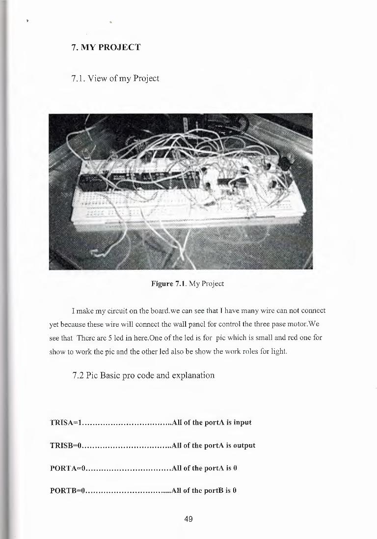
7. MY PROJECT
7 .1. View of my Project
Figure 7.1. My Project
I make my circuit on the board.we can see that I have many wire can not connect
yet because these wire will connect the wall panel for control the three pase motor.We
see that There are 5 led in here.One of the led is for pie which is small and red one for
show to work the pie and the other led also be show the work roles for light.
7 .2 Pie Basic pro code and explanation
TRISA=l. All of the portA is input
TRISB=O All of the portA is output
PORTA=O All of the portA is 0
PORTB=O All of the portB is 0
49
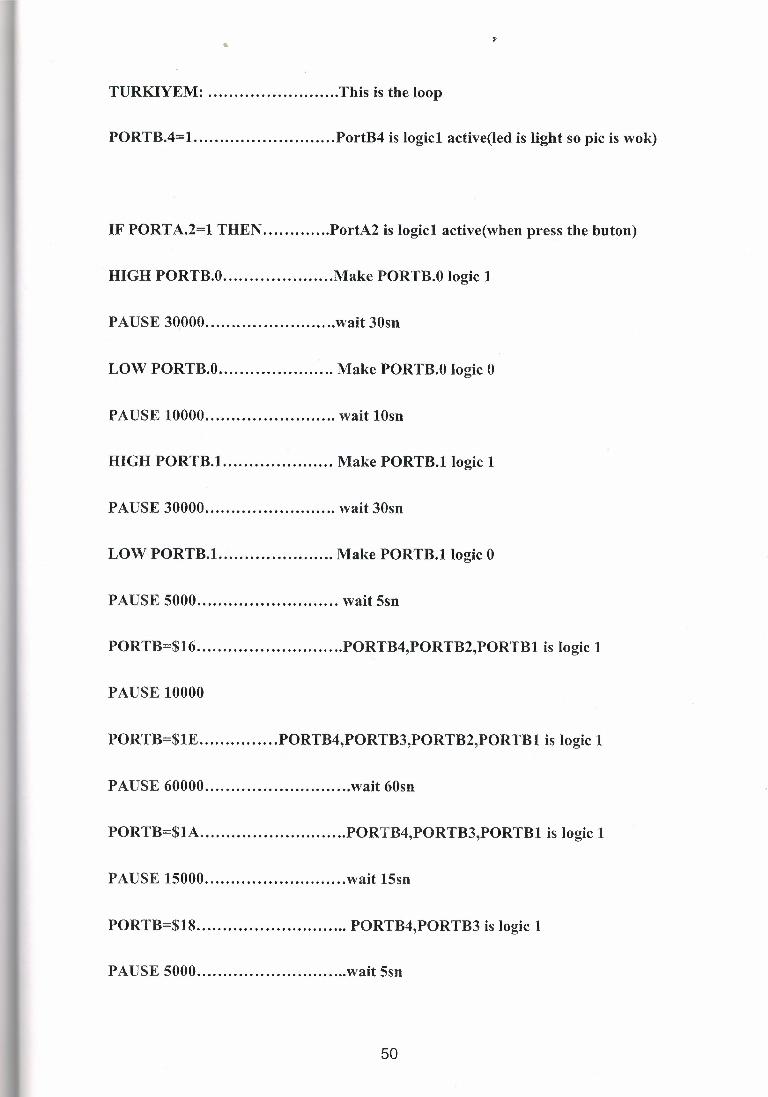
••
TURKIYEM: This is the loop
PORTB.4=1. PortB4 is logicl active(led is light so pie is wok)
IF PORTA.2=1 THEN PortA2 is logicl active(when press the buton)
HIGH PORTB.O Make PORTB.O logic 1
PAUSE 3QOOO wait 30sn
LOW PORTB.O Make PORTB.O logic 0
PAUSE 10000 wait lOsn
HIGH PORTB.1. Make PORTB.1 logic 1
PAUSE 30000 wait 30sn
LOW PORTB.1. Make PORTB.1 logic 0
PAUSE 5000 wait 5sn
PORTB=$16 PORTB4,PORTB2,PORTB1 is logic 1
PAUSE 10000
PORTB=$1E PORTB4,PORTB3,PORTB2,PORTB1 is logic 1
PAUSE 60000 wait 60sn
PORTB=$1A PORTB4,PORTB3,PORTB1 is logic 1
PAUSE 15000 wait 15sn
PORTB=$18 PORTB4,PORTB3 is logic 1
PAUSE 5000 wait 5sn
50
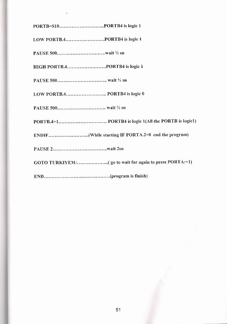
PORTB=$10 PORTB4 is logic 1
LOW PORTB.4 PORTB4 is logic 1
PAUSE 500 wait Yi sn
HIGH PORTB.4 PORTB4 is logic 1
PAUSE 500 wait Yi sn
LOW PORTB.4 PORTB4 is logic 0
PAUSE 500 wait Yi sn
PORTB.4=1. PORTB4 is logic l(All the PORTB is logicl)
ENDIF (While starting IF PORTA.2=0 end the program)
PAUSE 2 wait 2sn
GOTO TURKIYEM: ( go to wait for again to press PORTA:=1)
END (program is finish)
51

••
CONCLUSION
Pie is very useful device and also pie is not expensive device so choose this
device instead of PLC from some where.PLC is expensive than pie because of this we
can do much more thing to low price with use pie.Pie programming is not difficult
because of advantage the Pie Basic pro. Now a day new kind of products develop so engineers should follow these
product for backgraunds.Basic Step is also good example.Many websites include
different information about it.Basic step is like Picbasic pro but also its more easy and
has not much more auxiliary device like cristal in the circut.
When connect the system on the wall panel andto take into consideration of
connections error and focus on working while use high voltage.
Every step of the programming pie while use Microcod Studio and le prog
programs errors can be found so that solving the error can learned.
52
REFERENCES
[1] http:// www.rentron.com
[2] Pie Basic pro Compiler Book microEngineering Labs. Inc. 2004
[3] Prf.Dr.Dogan Ibrahim Lecture Notes
[ 4] http://hyperphysics.phy-astr.gsu.edu/hbase/solids/ diod.html
[5] http:// www.ke4nyv.com
[6] http://www.microchip.com
[7] Engineering Dictionary McGraw-Hill
[8) http://www.wikipedia.com
[9] http://v-,1ww.melabs.com
[10) www.motorola.com
[11) Basic for Pie Microcontrollers Nebojsa Matic
[12) http://www.motionNET.com
[13) http://www.alldatasheets.com
[14) http://www.pcsistem.net
53


Wl,ı\.~~rııl'I'S.....i ı\]J~~](https://img.pdfslide.us/doc/110x75/6063d0332f94ab26ab40ccdd/near-east-university-faculty-of-tableofcontents-cliwlrlisi.jpg)