Embed Size (px)
Citation preview

Near-Capacity Multi-Functional MIMO
Systems:Sphere-Packing, Iterative Detection and Cooperation
by
L. Hanzo, O. R. Alamri, M. El-Hajjar, N. Wu
We dedicate this monograph to the numerous contributors of this field, many of
whom are listed in the Author Index
The classic Shannon-Hartley law suggests that the achievable channel capacity
increases logarithmically with the transmit power. By contrast, the MIMO capacity
increases linearly with the number of transmit antennas, provided that the number
of receive antennas is equal to the number of transmit antennas. With the further
proviso that the total transmit power is increased proportionately to the number of
transmit antennas, a linear capacity increase is achieved upon increasing the
transmit power, which justifies the spectacular success of MIMOs...
School of Electronics and Computer ScienceUniversity of SouthamptonSouthampton SO17 1BJ
United Kingdom

Contents
About the Authors x
Other Wiley and IEEE Press Books on Related Topics xii
Acknowledgments xv
Preface 1
1 Problem Formulation, Objectives and Benefits 31.1 The Wireless Channel and the Concept of Diversity . . . . . . . . . . . . . . . . . 41.2 Diversity and Multiplexing Tradeoffs in Multi-functional MIMO Systems . . . . . . 5
1.2.1 Classification of Multiple-Input Multiple-Output Systems . . . . . . . . . . 51.2.2 Multi-functional MIMO Systems . . . . . . . . . . . . . . . . . . . . . . . . 8
1.2.2.1 Layered Steered Space-Time Codes . . . . . . . . . . . . . . . . . 81.2.2.2 Layered Steered Space-Time Spreading . . . . . . . . . . . . . . . 9
1.2.3 Expected Performance and Discussions . . . . . . . . . . . . . . . . . . . . . 111.2.4 Diversity versus Multiplexing Tradeoffs in MIMO Systems . . . . . . . . . . 13
1.3 Coherent vs. Non-Coherent Detection for STBCs Using Co-located and CooperativeAntenna Elements . . . . . . . . . . . . . . . . . . . . . . . . . . . . . . . . . . . . 141.3.1 Motivation . . . . . . . . . . . . . . . . . . . . . . . . . . . . . . . . . . . . 141.3.2 Evolution of Space-Time Block Codes . . . . . . . . . . . . . . . . . . . . . 15
1.3.2.1 Orthogonal Approach . . . . . . . . . . . . . . . . . . . . . . . . . 161.3.2.2 Layered Approach . . . . . . . . . . . . . . . . . . . . . . . . . . . 161.3.2.3 Linear Dispersion Codes . . . . . . . . . . . . . . . . . . . . . . . 17
1.3.3 Differential STBCs Using Colocated Antenna Elements . . . . . . . . . . . 181.3.4 Cooperative STBCs Using Distributed Antenna Elements . . . . . . . . . . 201.3.5 Performance for Imperfect Channel Estimates and Shadow-Fading . . . . . 22
1.4 Historic Perspective and Sate-of-the-art Contributions . . . . . . . . . . . . . . . . 251.4.1 Colocated MIMO Techniques . . . . . . . . . . . . . . . . . . . . . . . . . . 25
1.4.1.1 Diversity Techniques . . . . . . . . . . . . . . . . . . . . . . . . . . 251.4.1.2 Multiplexing Techniques . . . . . . . . . . . . . . . . . . . . . . . 291.4.1.3 Beamforming Techniques . . . . . . . . . . . . . . . . . . . . . . . 301.4.1.4 Multi-functional MIMO Techniques . . . . . . . . . . . . . . . . . 31
1.4.2 Distributed MIMO Techniques . . . . . . . . . . . . . . . . . . . . . . . . . 331.5 Iterative Detection Schemes and Their Convergence Analysis . . . . . . . . . . . . 361.6 Outline and Novel Aspects of the Monograph . . . . . . . . . . . . . . . . . . . . . 38
1.6.1 Outline of the Book . . . . . . . . . . . . . . . . . . . . . . . . . . . . . . . 381.6.2 Novel Aspects of the Book . . . . . . . . . . . . . . . . . . . . . . . . . . . . 44
iii

iv CONTENTS
I Coherent Versus Differential Turbo-Detection of Sphere-PackingAided Single-User MIMO Systems 49
List of Symbols in Part I of the Book 51
2 Space-Time Block Code Design Using Sphere Packing 552.1 Introduction . . . . . . . . . . . . . . . . . . . . . . . . . . . . . . . . . . . . . . . . 552.2 Design Criteria for Space-Time Signals . . . . . . . . . . . . . . . . . . . . . . . . . 56
2.2.1 Channel Model . . . . . . . . . . . . . . . . . . . . . . . . . . . . . . . . . . 562.2.2 Pairwise Error Probability and Design Criterion . . . . . . . . . . . . . . . 58
2.3 Design Criteria for Time-Correlated Fading Channels . . . . . . . . . . . . . . . . . 592.3.1 Preliminaries . . . . . . . . . . . . . . . . . . . . . . . . . . . . . . . . . . . 592.3.2 Pairwise Error Probability and Design Criterion . . . . . . . . . . . . . . . 602.3.3 Coding Advantage . . . . . . . . . . . . . . . . . . . . . . . . . . . . . . . . 60
2.3.3.1 Generalised Diversity Product . . . . . . . . . . . . . . . . . . . . 612.3.3.2 Upper and Lower Bounds on the Generalised Diversity Product . 61
2.4 Orthogonal ST-Code Design Using Sphere Packing . . . . . . . . . . . . . . . . . . 622.4.1 General Concept of Sphere Packing . . . . . . . . . . . . . . . . . . . . . . . 62
2.4.1.1 The Sphere Packing Problem . . . . . . . . . . . . . . . . . . . . . 622.4.1.2 Representation of n-dimensional Real Euclidean Space Rn . . . . 632.4.1.3 Kepler Conjecture . . . . . . . . . . . . . . . . . . . . . . . . . . . 632.4.1.4 Kissing Numbers . . . . . . . . . . . . . . . . . . . . . . . . . . . . 632.4.1.5 n-dimensional Packings . . . . . . . . . . . . . . . . . . . . . . . . 632.4.1.6 Applications of Sphere Packing . . . . . . . . . . . . . . . . . . . . 64
2.4.2 Sphere-Packing Aided STBC Concept . . . . . . . . . . . . . . . . . . . . . 652.4.3 Signal Design for Two Transmit Antennas . . . . . . . . . . . . . . . . . . . 68
2.4.3.1 G2 Space-Time Encoding . . . . . . . . . . . . . . . . . . . . . . . 692.4.3.2 Receiver and Maximum Likelihood Decoding . . . . . . . . . . . . 702.4.3.3 G2 Space-Time Coding Using Multiple Receive Antennas . . . . . 732.4.3.4 G2 Orthogonal Design Using Sphere Packing . . . . . . . . . . . . 74
2.4.4 Sphere Packing Constellation Construction . . . . . . . . . . . . . . . . . . 772.4.5 Capacity of STBC-SP Schemes . . . . . . . . . . . . . . . . . . . . . . . . . 80
2.5 STBC-SP Performance . . . . . . . . . . . . . . . . . . . . . . . . . . . . . . . . . . 832.6 Chapter Conclusion . . . . . . . . . . . . . . . . . . . . . . . . . . . . . . . . . . . 872.7 Chapter Summary . . . . . . . . . . . . . . . . . . . . . . . . . . . . . . . . . . . . 88
3 Turbo Detection of Channel-Coded STBC-SP Schemes 953.1 Introduction . . . . . . . . . . . . . . . . . . . . . . . . . . . . . . . . . . . . . . . . 953.2 System Overview . . . . . . . . . . . . . . . . . . . . . . . . . . . . . . . . . . . . . 96
3.2.1 RSC-Coded Turbo-Detected STBC-SP scheme . . . . . . . . . . . . . . . . 963.2.2 Binary LDPC-Coded Turbo-Detected STBC-SP scheme . . . . . . . . . . . 97
3.3 Iterative Demapping . . . . . . . . . . . . . . . . . . . . . . . . . . . . . . . . . . . 983.4 Binary EXIT Chart Analysis . . . . . . . . . . . . . . . . . . . . . . . . . . . . . . 100
3.4.1 Transfer Characteristics of the Demapper . . . . . . . . . . . . . . . . . . . 1013.4.2 Transfer Characteristics of the Outer Decoder . . . . . . . . . . . . . . . . . 1053.4.3 Extrinsic Information Transfer Chart . . . . . . . . . . . . . . . . . . . . . . 106
3.5 Performance of Turbo-Detected Bit-Based STBC-SP Schemes . . . . . . . . . . . . 1073.5.1 Performance of RSC-coded STBC-SP Scheme . . . . . . . . . . . . . . . . . 108
3.5.1.1 Mutual Information and Achievable BER . . . . . . . . . . . . . . 1083.5.1.2 Decoding Trajectory and Effect of Interleaver Depth . . . . . . . . 1093.5.1.3 BER Performance . . . . . . . . . . . . . . . . . . . . . . . . . . . 112
3.5.2 Performance of Binary LDPC-coded STBC-SP scheme . . . . . . . . . . . . 1163.5.2.1 Mutual Information and Achievable BER . . . . . . . . . . . . . . 1163.5.2.2 Decoding Trajectory and Effect of Interleaver Depth . . . . . . . . 117

CONTENTS v
3.5.2.3 Effect of Internal LDPC Iterations and Joint External Iterations . 1183.6 Chapter Conclusion . . . . . . . . . . . . . . . . . . . . . . . . . . . . . . . . . . . 1193.7 Chapter Summary . . . . . . . . . . . . . . . . . . . . . . . . . . . . . . . . . . . . 120
4 Turbo Detection of Channel-Coded DSTBC-SP Schemes 1254.1 Introduction . . . . . . . . . . . . . . . . . . . . . . . . . . . . . . . . . . . . . . . . 1254.2 Differential STBC Using Sphere Packing Modulation . . . . . . . . . . . . . . . . . 126
4.2.1 DSTBC Signal Design Using Sphere Packing Modulation . . . . . . . . . . 1264.2.2 Performance of DSTBC-SP Schemes . . . . . . . . . . . . . . . . . . . . . . 128
4.2.2.1 Block Rayleigh Fading Channels . . . . . . . . . . . . . . . . . . . 1294.2.2.2 SPSI Rayleigh Fading Channels . . . . . . . . . . . . . . . . . . . 130
4.3 Bit-Based RSC-Coded Turbo-Detected DSTBC-SP scheme . . . . . . . . . . . . . 1314.3.1 System Overview . . . . . . . . . . . . . . . . . . . . . . . . . . . . . . . . . 1334.3.2 EXIT Chart Analysis . . . . . . . . . . . . . . . . . . . . . . . . . . . . . . 1394.3.3 Performance of the RSC-coded DSTBC-SP scheme . . . . . . . . . . . . . . 142
4.4 Chapter Conclusion . . . . . . . . . . . . . . . . . . . . . . . . . . . . . . . . . . . 1484.5 Chapter Summary . . . . . . . . . . . . . . . . . . . . . . . . . . . . . . . . . . . . 152
5 Three-Stage Turbo-Detected STBC-SP Schemes 1555.1 Introduction . . . . . . . . . . . . . . . . . . . . . . . . . . . . . . . . . . . . . . . . 1555.2 System Overview . . . . . . . . . . . . . . . . . . . . . . . . . . . . . . . . . . . . . 156
5.2.1 Encoder . . . . . . . . . . . . . . . . . . . . . . . . . . . . . . . . . . . . . . 1565.2.2 Channel Model . . . . . . . . . . . . . . . . . . . . . . . . . . . . . . . . . . 1575.2.3 Decoder . . . . . . . . . . . . . . . . . . . . . . . . . . . . . . . . . . . . . . 157
5.3 EXIT Chart Analysis . . . . . . . . . . . . . . . . . . . . . . . . . . . . . . . . . . . 1585.3.1 Preliminaries . . . . . . . . . . . . . . . . . . . . . . . . . . . . . . . . . . . 1585.3.2 3D EXIT Charts . . . . . . . . . . . . . . . . . . . . . . . . . . . . . . . . . 1585.3.3 2D EXIT Chart Projections . . . . . . . . . . . . . . . . . . . . . . . . . . . 1605.3.4 EXIT Tunnel-Area Minimisation for Near-Capacity Operation . . . . . . . 163
5.4 Maximum Achievable Bandwidth Efficiency . . . . . . . . . . . . . . . . . . . . . . 1655.5 Performance of Three-Stage Turbo-Detected STBC-SP Schemes . . . . . . . . . . . 167
5.5.1 System Parameters . . . . . . . . . . . . . . . . . . . . . . . . . . . . . . . . 1675.5.2 Three-Stage RA-Coded STBC-SP Scheme . . . . . . . . . . . . . . . . . . . 168
5.5.2.1 Decoding Trajectory . . . . . . . . . . . . . . . . . . . . . . . . . . 1685.5.2.2 BER Performance . . . . . . . . . . . . . . . . . . . . . . . . . . . 1685.5.2.3 Effect of Interleaver Depth . . . . . . . . . . . . . . . . . . . . . . 169
5.5.3 Three-Stage RSC-Coded STBC-SP Scheme . . . . . . . . . . . . . . . . . . 1695.5.3.1 Decoding Trajectory . . . . . . . . . . . . . . . . . . . . . . . . . . 1695.5.3.2 BER Performance . . . . . . . . . . . . . . . . . . . . . . . . . . . 1705.5.3.3 Effect of Interleaver Depth . . . . . . . . . . . . . . . . . . . . . . 171
5.5.4 Three-Stage IRCC-Coded STBC-SP Scheme . . . . . . . . . . . . . . . . . 1725.5.4.1 Decoding Trajectory . . . . . . . . . . . . . . . . . . . . . . . . . . 1725.5.4.2 BER Performance . . . . . . . . . . . . . . . . . . . . . . . . . . . 1725.5.4.3 Effect of Interleaver Depth . . . . . . . . . . . . . . . . . . . . . . 173
5.5.5 Performance Comparison of Three-stage STBC-SP Schemes . . . . . . . . . 1745.6 Chapter Conclusion . . . . . . . . . . . . . . . . . . . . . . . . . . . . . . . . . . . 1765.7 Chapter Summary . . . . . . . . . . . . . . . . . . . . . . . . . . . . . . . . . . . . 176
6 Symbol-Based Channel-Coded STBC-SP Schemes 1836.1 Introduction . . . . . . . . . . . . . . . . . . . . . . . . . . . . . . . . . . . . . . . . 1836.2 System Overview . . . . . . . . . . . . . . . . . . . . . . . . . . . . . . . . . . . . . 184
6.2.1 Symbol-Based LDPC-Coded STBC-SP Scheme . . . . . . . . . . . . . . . . 1846.2.2 Bit-Based LDPC-Coded STBC-SP Scheme . . . . . . . . . . . . . . . . . . 186
6.3 Symbol-Based Iterative Decoding . . . . . . . . . . . . . . . . . . . . . . . . . . . . 186

vi CONTENTS
6.4 Non-Binary EXIT Chart Analysis . . . . . . . . . . . . . . . . . . . . . . . . . . . . 1886.4.1 Calculation of Non-Binary EXIT Charts . . . . . . . . . . . . . . . . . . . . 1886.4.2 Generating the A Priori Symbol Probabilities . . . . . . . . . . . . . . . . 190
6.4.2.1 Case I: The Binary Bits of a Non-Binary Symbol Are Independent 1906.4.2.2 Case II: The Binary Bits of a Non-Binary Symbol Are Not Inde-
pendent . . . . . . . . . . . . . . . . . . . . . . . . . . . . . . . . . 1906.4.3 EXIT Chart Results . . . . . . . . . . . . . . . . . . . . . . . . . . . . . . . 194
6.4.3.1 EXIT Charts of Symbol-Based Schemes . . . . . . . . . . . . . . . 1946.4.3.2 EXIT Charts of Bit-Based Schemes . . . . . . . . . . . . . . . . . 1956.4.3.3 Comparison of the EXIT Charts of Symbol-Based and Bit-Based
Schemes . . . . . . . . . . . . . . . . . . . . . . . . . . . . . . . . . 1956.5 Performance of Bit-Based and Symbol-Based STBC-SP Schemes . . . . . . . . . . 197
6.5.1 System Parameters . . . . . . . . . . . . . . . . . . . . . . . . . . . . . . . . 1976.5.2 Decoding Trajectory . . . . . . . . . . . . . . . . . . . . . . . . . . . . . . . 1996.5.3 BER Performance . . . . . . . . . . . . . . . . . . . . . . . . . . . . . . . . 2006.5.4 Effect of Interleaver Depth . . . . . . . . . . . . . . . . . . . . . . . . . . . 200
6.6 Chapter Conclusion . . . . . . . . . . . . . . . . . . . . . . . . . . . . . . . . . . . 2026.7 Chapter Summary . . . . . . . . . . . . . . . . . . . . . . . . . . . . . . . . . . . . 203
II Coherent Versus Differential Turbo-Detection of Single-User andCooperative MIMOs 209
7 Linear Dispersion Codes – An EXIT Chart Perspective 2117.1 Introduction and Outline . . . . . . . . . . . . . . . . . . . . . . . . . . . . . . . . 2117.2 Linear Dispersion Codes . . . . . . . . . . . . . . . . . . . . . . . . . . . . . . . . . 215
7.2.1 Channel Model . . . . . . . . . . . . . . . . . . . . . . . . . . . . . . . . . . 2157.2.2 Linear Dispersion Code Model of [29] . . . . . . . . . . . . . . . . . . . . . 2157.2.3 Linear Dispersion Code Model of [28] . . . . . . . . . . . . . . . . . . . . . 2187.2.4 Maximizing the Discrete LDC Capacity . . . . . . . . . . . . . . . . . . . . 2207.2.5 Performance Results . . . . . . . . . . . . . . . . . . . . . . . . . . . . . . . 2227.2.6 Summary . . . . . . . . . . . . . . . . . . . . . . . . . . . . . . . . . . . . . 227
7.3 Link Between STBCs and LDCs . . . . . . . . . . . . . . . . . . . . . . . . . . . . 2307.3.1 Review of Existing STBC Knowledge . . . . . . . . . . . . . . . . . . . . . 2307.3.2 Orthogonal STBCs . . . . . . . . . . . . . . . . . . . . . . . . . . . . . . . . 2327.3.3 Quasi-Orthogonal Space-Time Block Codes . . . . . . . . . . . . . . . . . . 2337.3.4 Linear STBCs Based on Amicable Orthogonal Designs . . . . . . . . . . . . 2337.3.5 Single-Symbol-Decodable STBCs Based on QOSTBCs . . . . . . . . . . . 2347.3.6 Space-Time Codes Using Time Varying Linear Transformation . . . . . . . 2347.3.7 Threaded Algebraic Space-Time Codes . . . . . . . . . . . . . . . . . . . . . 2357.3.8 Summary . . . . . . . . . . . . . . . . . . . . . . . . . . . . . . . . . . . . . 236
7.4 EXIT Chart Based Design of LDCs . . . . . . . . . . . . . . . . . . . . . . . . . . . 2387.4.1 Analyzing Iteratively-Detected LDCs . . . . . . . . . . . . . . . . . . . . . . 2387.4.2 Analyzing Iteratively-Detected Precoded LDCs . . . . . . . . . . . . . . . . 2437.4.3 Summary . . . . . . . . . . . . . . . . . . . . . . . . . . . . . . . . . . . . . 248
7.5 EXIT Chart Based Design of IrRegular Precoded LDCs . . . . . . . . . . . . . . . 2497.5.1 RSC-coded IR-PLDC Scheme . . . . . . . . . . . . . . . . . . . . . . . . . . 249
7.5.1.1 Generating Component Codes for IR-PLDCs . . . . . . . . . . . . 2517.5.1.2 Maximum-Rate RSC-Coded IR-PLDCs . . . . . . . . . . . . . . . 2567.5.1.3 Complexity-Constrained RSC-Coded IR-PLDCs . . . . . . . . . . 261
7.5.2 IR-PLDCs Vs. IRCCs . . . . . . . . . . . . . . . . . . . . . . . . . . . . . . 2647.5.3 IRCC-Coded IR-PLDC Scheme . . . . . . . . . . . . . . . . . . . . . . . . . 2667.5.4 Summary . . . . . . . . . . . . . . . . . . . . . . . . . . . . . . . . . . . . . 269
7.6 Conclusion . . . . . . . . . . . . . . . . . . . . . . . . . . . . . . . . . . . . . . . . 271

CONTENTS vii
8 Differential Space-Time Block Codes: A Universal Approach 273
8.1 Introduction and Outline . . . . . . . . . . . . . . . . . . . . . . . . . . . . . . . . 273
8.2 System Model . . . . . . . . . . . . . . . . . . . . . . . . . . . . . . . . . . . . . . . 274
8.2.1 DPSK System Model for Single Antennas . . . . . . . . . . . . . . . . . . . 274
8.2.2 DSTBC System Model for Multiple Antennas . . . . . . . . . . . . . . . . . 275
8.2.3 Link Between STBCs and DSTBCs . . . . . . . . . . . . . . . . . . . . . . . 277
8.3 Differential Orthogonal STBCs . . . . . . . . . . . . . . . . . . . . . . . . . . . . . 278
8.3.1 Differential Alamouti Codes . . . . . . . . . . . . . . . . . . . . . . . . . . . 278
8.3.1.1 Using QAM Constellations . . . . . . . . . . . . . . . . . . . . . . 279
8.3.2 DOSTBCs for Four Transmit Antennas . . . . . . . . . . . . . . . . . . . . 280
8.3.3 DOSTBCs Based on QOSTBCs . . . . . . . . . . . . . . . . . . . . . . . . . 281
8.3.4 DOSTBCs Based on LSTBCs and SSD-STBCs . . . . . . . . . . . . . . . . 282
8.3.5 Performance Results . . . . . . . . . . . . . . . . . . . . . . . . . . . . . . . 283
8.3.6 Summary . . . . . . . . . . . . . . . . . . . . . . . . . . . . . . . . . . . . . 287
8.4 Differential Linear Dispersion Codes . . . . . . . . . . . . . . . . . . . . . . . . . . 288
8.4.1 Evolution to a Linear Structure . . . . . . . . . . . . . . . . . . . . . . . . . 288
8.4.2 Differential LDCs Based on the Cayley Transform . . . . . . . . . . . . . . 289
8.4.2.1 The Cayley Transform . . . . . . . . . . . . . . . . . . . . . . . . . 289
8.4.2.2 Differential Encoding/Decoding . . . . . . . . . . . . . . . . . . . 290
8.4.2.3 Examples of DLDCs Based on the Cayley Transform . . . . . . . 292
8.4.3 Performance Results . . . . . . . . . . . . . . . . . . . . . . . . . . . . . . . 293
8.4.4 Summary . . . . . . . . . . . . . . . . . . . . . . . . . . . . . . . . . . . . . 296
8.5 RSC-Coded Precoder-Aided DOSTBCs . . . . . . . . . . . . . . . . . . . . . . . . 299
8.5.1 DOSTBC Design With Sphere Packing Modulation . . . . . . . . . . . . . . 300
8.5.2 System Description . . . . . . . . . . . . . . . . . . . . . . . . . . . . . . . . 301
8.5.3 EXIT Chart Analysis . . . . . . . . . . . . . . . . . . . . . . . . . . . . . . 302
8.5.4 Performance Results . . . . . . . . . . . . . . . . . . . . . . . . . . . . . . . 305
8.6 IRCC-Coded Precoder-Aided DLDCs . . . . . . . . . . . . . . . . . . . . . . . . . . 307
8.6.1 EXIT Chart Based IR-PDLDC Design . . . . . . . . . . . . . . . . . . . . . 307
8.6.2 Performance Results . . . . . . . . . . . . . . . . . . . . . . . . . . . . . . . 311
8.7 Conclusion . . . . . . . . . . . . . . . . . . . . . . . . . . . . . . . . . . . . . . . . 313
9 Cooperative Space-Time Block Codes 315
9.1 Introduction and Outline . . . . . . . . . . . . . . . . . . . . . . . . . . . . . . . . 315
9.2 Twin-Layer Cooperative Linear Dispersion Codes . . . . . . . . . . . . . . . . . . . 317
9.2.1 System Model . . . . . . . . . . . . . . . . . . . . . . . . . . . . . . . . . . . 317
9.2.2 System Assumptions . . . . . . . . . . . . . . . . . . . . . . . . . . . . . . . 318
9.2.3 Mathematical Representations . . . . . . . . . . . . . . . . . . . . . . . . . 320
9.2.4 Link Between CLDCs and LDCs . . . . . . . . . . . . . . . . . . . . . . . . 323
9.2.5 Performance Results . . . . . . . . . . . . . . . . . . . . . . . . . . . . . . . 325
9.3 IRCC-coded Precoder-Aided CLDCs . . . . . . . . . . . . . . . . . . . . . . . . . . 333
9.3.1 EXIT Chart Based IR-PCLDC Design . . . . . . . . . . . . . . . . . . . . . 333
9.3.2 Performance Results . . . . . . . . . . . . . . . . . . . . . . . . . . . . . . . 338
9.4 Conclusion . . . . . . . . . . . . . . . . . . . . . . . . . . . . . . . . . . . . . . . . 341
III Differential Turbo-Detection of Multi-Functional MIMO-AidedMulti-User and Cooperative Systems 343
List of Symbols in Part III of the Book 345

viii CONTENTS
10 Differential Space-Time Spreading 34910.1 Introduction . . . . . . . . . . . . . . . . . . . . . . . . . . . . . . . . . . . . . . . . 34910.2 Differential Phase Shift Keying . . . . . . . . . . . . . . . . . . . . . . . . . . . . . 35010.3 DSTS Design Using Two Transmit Antennas . . . . . . . . . . . . . . . . . . . . . 351
10.3.1 Encoding Using Conventional Modulation . . . . . . . . . . . . . . . . . . . 35210.3.2 Receiver and Maximum Likelihood Decoding . . . . . . . . . . . . . . . . . 35310.3.3 Design Using Sphere Packing Modulation . . . . . . . . . . . . . . . . . . . 35510.3.4 Sphere Packing Constellation Construction . . . . . . . . . . . . . . . . . . 35810.3.5 Bandwidth Efficiency of the Twin-Antenna-Aided DSTS System . . . . . . 35910.3.6 Capacity of the Two-Antenna-Aided DSTS-SP Scheme . . . . . . . . . . . . 36010.3.7 Performance of the Two-Antenna-Aided DSTS System . . . . . . . . . . . . 366
10.4 DSTS Design Using Four Transmit Antennas . . . . . . . . . . . . . . . . . . . . . 37510.4.1 Design Using Real-Valued Constellations . . . . . . . . . . . . . . . . . . . . 37510.4.2 Design Using Complex-Valued Constellations . . . . . . . . . . . . . . . . . 37810.4.3 Design Using Sphere Packing Modulation . . . . . . . . . . . . . . . . . . . 37810.4.4 Bandwidth Efficiency of the Four-Antenna-Aided DSTS Scheme . . . . . . 38010.4.5 Capacity of the Four-Antenna-Aided DSTS-SP Scheme . . . . . . . . . . . 38110.4.6 Performance of the Four-Antenna-Aided DSTS Scheme . . . . . . . . . . . 381
10.5 Chapter Conclusion . . . . . . . . . . . . . . . . . . . . . . . . . . . . . . . . . . . 38610.6 Chapter Summary . . . . . . . . . . . . . . . . . . . . . . . . . . . . . . . . . . . . 390
11 Iterative Detection of Channel-Coded DSTS Schemes 39311.1 Introduction . . . . . . . . . . . . . . . . . . . . . . . . . . . . . . . . . . . . . . . . 39311.2 Iterative Detection of RSC-Coded DSTS Schemes . . . . . . . . . . . . . . . . . . . 394
11.2.1 Iterative Demapping . . . . . . . . . . . . . . . . . . . . . . . . . . . . . . . 39611.2.1.1 Conventional Modulation . . . . . . . . . . . . . . . . . . . . . . . 39611.2.1.2 Sphere Packing Modulation . . . . . . . . . . . . . . . . . . . . . . 396
11.2.2 EXIT Chart Analysis . . . . . . . . . . . . . . . . . . . . . . . . . . . . . . 39711.2.2.1 Transfer Characteristics of the Demapper . . . . . . . . . . . . . . 39811.2.2.2 Transfer Characteristics of the Outer Decoder . . . . . . . . . . . 40011.2.2.3 Extrinsic Information Transfer Chart . . . . . . . . . . . . . . . . 402
11.2.3 Maximum Achievable Bandwidth Efficiency . . . . . . . . . . . . . . . . . . 40611.2.4 Results and Discussions . . . . . . . . . . . . . . . . . . . . . . . . . . . . . 40911.2.5 Application . . . . . . . . . . . . . . . . . . . . . . . . . . . . . . . . . . . . 421
11.3 Iterative Detection of RSC- and URC-Coded DSTS-SP System . . . . . . . . . . . 42411.3.1 System Overview . . . . . . . . . . . . . . . . . . . . . . . . . . . . . . . . . 42411.3.2 Results and Discussions . . . . . . . . . . . . . . . . . . . . . . . . . . . . . 42511.3.3 Application . . . . . . . . . . . . . . . . . . . . . . . . . . . . . . . . . . . . 430
11.3.3.1 IrVLC Design Using EXIT Chart Analysis . . . . . . . . . . . . . 43211.3.3.2 Performance Results . . . . . . . . . . . . . . . . . . . . . . . . . . 432
11.4 Chapter Conclusion . . . . . . . . . . . . . . . . . . . . . . . . . . . . . . . . . . . 43511.5 Chapter Summary . . . . . . . . . . . . . . . . . . . . . . . . . . . . . . . . . . . . 435
12 Adaptive DSTS-Assisted Iteratively-Detected SP Modulation 43912.1 Introduction . . . . . . . . . . . . . . . . . . . . . . . . . . . . . . . . . . . . . . . . 43912.2 System Overview . . . . . . . . . . . . . . . . . . . . . . . . . . . . . . . . . . . . . 44112.3 Adaptive DSTS-Assisted SP Modulation . . . . . . . . . . . . . . . . . . . . . . . . 442
12.3.1 Single Layer Four-Antenna-Aided DSTS-SP System . . . . . . . . . . . . . 44312.3.2 Twin Layer Four-Antenna-Aided DSTS-SP System . . . . . . . . . . . . . . 444
12.4 Variable Spreading Factor Based Adaptive Rate DSTS . . . . . . . . . . . . . . . . 44612.5 Variable Code Rate Iteratively Detected DSTS-SP System . . . . . . . . . . . . . . 44712.6 Results and Discussions . . . . . . . . . . . . . . . . . . . . . . . . . . . . . . . . . 44712.7 Chapter Conclusion and Summary . . . . . . . . . . . . . . . . . . . . . . . . . . . 450

CONTENTS ix
13 Layered Steered Space-Time Codes 45113.1 Introduction . . . . . . . . . . . . . . . . . . . . . . . . . . . . . . . . . . . . . . . . 45113.2 Layered Steered Space-Time Codes . . . . . . . . . . . . . . . . . . . . . . . . . . . 453
13.2.1 LSSTC Using Conventional Modulation . . . . . . . . . . . . . . . . . . . . 45313.2.2 LSSTC Using SP Modulation . . . . . . . . . . . . . . . . . . . . . . . . . . 455
13.3 Capacity of Layered Steered Space-Time Codes . . . . . . . . . . . . . . . . . . . . 45613.4 Iterative Detection and EXIT Chart Analysis . . . . . . . . . . . . . . . . . . . . . 461
13.4.1 Two-Stage Iterative Detection Scheme . . . . . . . . . . . . . . . . . . . . . 46213.4.1.1 2D EXIT Charts . . . . . . . . . . . . . . . . . . . . . . . . . . . . 46313.4.1.2 EXIT Tunnel-Area Minimisation for Near-Capacity Operation Us-
ing IrCCs . . . . . . . . . . . . . . . . . . . . . . . . . . . . . . . . 46513.4.2 Three-Stage Iterative Detection Scheme . . . . . . . . . . . . . . . . . . . . 467
13.4.2.1 3D EXIT Charts . . . . . . . . . . . . . . . . . . . . . . . . . . . . 46813.4.2.2 2D EXIT Chart Projection . . . . . . . . . . . . . . . . . . . . . . 470
13.4.3 Maximum Achievable Bandwidth Efficiency . . . . . . . . . . . . . . . . . . 47313.5 Results and Discussion . . . . . . . . . . . . . . . . . . . . . . . . . . . . . . . . . . 47513.6 Chapter Conclusion . . . . . . . . . . . . . . . . . . . . . . . . . . . . . . . . . . . 48013.7 Chapter Summary . . . . . . . . . . . . . . . . . . . . . . . . . . . . . . . . . . . . 480
14 Downlink LSSTS Aided Generalised MC DS-CDMA 48314.1 Introduction . . . . . . . . . . . . . . . . . . . . . . . . . . . . . . . . . . . . . . . . 48314.2 LSSTS Aided Generalised MC DS-CDMA . . . . . . . . . . . . . . . . . . . . . . . 485
14.2.1 Transmitter Model . . . . . . . . . . . . . . . . . . . . . . . . . . . . . . . . 48614.2.2 Receiver Model . . . . . . . . . . . . . . . . . . . . . . . . . . . . . . . . . . 488
14.3 Increasing the Number of Users . . . . . . . . . . . . . . . . . . . . . . . . . . . . . 49214.3.1 Transmitter Model . . . . . . . . . . . . . . . . . . . . . . . . . . . . . . . . 49214.3.2 Receiver Model . . . . . . . . . . . . . . . . . . . . . . . . . . . . . . . . . . 49414.3.3 User Grouping Technique . . . . . . . . . . . . . . . . . . . . . . . . . . . . 495
14.4 Iterative Detection and EXIT Chart Analysis . . . . . . . . . . . . . . . . . . . . . 49714.4.1 EXIT Charts and LLR Post-processing . . . . . . . . . . . . . . . . . . . . 500
14.5 Results and Discussions . . . . . . . . . . . . . . . . . . . . . . . . . . . . . . . . . 50814.6 Chapter Conclusion . . . . . . . . . . . . . . . . . . . . . . . . . . . . . . . . . . . 51214.7 Chapter Summary . . . . . . . . . . . . . . . . . . . . . . . . . . . . . . . . . . . . 513
15 Distributed Turbo Coding 51515.1 Introduction . . . . . . . . . . . . . . . . . . . . . . . . . . . . . . . . . . . . . . . . 51515.2 Background of Cooperative Communications . . . . . . . . . . . . . . . . . . . . . 516
15.2.1 Amplify-and-Forward . . . . . . . . . . . . . . . . . . . . . . . . . . . . . . 51715.2.2 Decode-and-Forward . . . . . . . . . . . . . . . . . . . . . . . . . . . . . . . 51715.2.3 Coded Cooperation . . . . . . . . . . . . . . . . . . . . . . . . . . . . . . . . 518
15.3 Distributed Turbo Coding . . . . . . . . . . . . . . . . . . . . . . . . . . . . . . . . 51915.4 Results and Discussions . . . . . . . . . . . . . . . . . . . . . . . . . . . . . . . . . 52115.5 Conclusions . . . . . . . . . . . . . . . . . . . . . . . . . . . . . . . . . . . . . . . . 52915.6 Chapter Summary . . . . . . . . . . . . . . . . . . . . . . . . . . . . . . . . . . . . 530
16 Conclusions and Future Research 53116.1 Summary and Conclusions . . . . . . . . . . . . . . . . . . . . . . . . . . . . . . . . 531
16.1.1 Chapter 1: Problem Formulation, Objectives and Benefits . . . . . . . . . . 53116.1.2 Chapter 2: Space-Time Block Code Design Using Sphere Packing . . . . . . 53116.1.3 Chapter 3: Turbo Detection of Channel-Coded STBC-SP Schemes . . . . . 53216.1.4 Chapter 4: Turbo Detection of Channel-Coded DSTBC-SP Schemes . . . . 53416.1.5 Chapter 5: Three-Stage Turbo-Detected STBC-SP Schemes . . . . . . . . . 53616.1.6 Chapter 6: Symbol-Based Channel-Coded STBC-SP Schemes . . . . . . . . 53916.1.7 Chapter 7: IR-PLDCs for Co-located MIMO Antenna Elements . . . . . . . 540

x CONTENTS
16.1.8 Chapter 8: IR-PDLDCs for Co-located MIMO Antenna Elements . . . . . . 54216.1.9 Chapter 9: IR-PCLDCs for Cooperative MIMO Systems . . . . . . . . . . . 544
16.1.9.1 Linking LDCs, DLDCs and CLDCs . . . . . . . . . . . . . . . . . 54516.1.10Chapter 10: Differential Space-Time Spreading . . . . . . . . . . . . . . . . 54916.1.11Chapter 11: Iterative Detection of Channel-Coded DSTS Schemes . . . . . 55016.1.12Chapter 12: Adaptive DSTS-Assisted Iteratively-Detected SP Modulation . 55416.1.13Layered Steered Space-Time Codes . . . . . . . . . . . . . . . . . . . . . . . 55516.1.14Chapter 14: Downlink LSSTS Aided Generalised MC DS-CDMA . . . . . . 55816.1.15Chapter 15: Distributed Turbo Coding . . . . . . . . . . . . . . . . . . . . . 561
16.2 Future Research Ideas . . . . . . . . . . . . . . . . . . . . . . . . . . . . . . . . . . 56216.2.1 Generalised Turbo-Detected SP-Assisted Orthogonal Design . . . . . . . . . 56216.2.2 Precoder Design for Short Interleaver Depths . . . . . . . . . . . . . . . . . 56316.2.3 Improving the Coding Gain of V-BLAST Schemes . . . . . . . . . . . . . . 56416.2.4 Adaptive Closed-loop Co-located MIMO Systems . . . . . . . . . . . . . . . 56516.2.5 Improved Performance Cooperative MIMO Systems . . . . . . . . . . . . . 56616.2.6 Differential Multi-functional MIMO . . . . . . . . . . . . . . . . . . . . . . 56616.2.7 Multi-functional Cooperative Communication Systems . . . . . . . . . . . . 56716.2.8 Soft Relaying and Power Optimisation in Distributed Turbo Coding . . . . 568
A Mapping Schemes for Sphere Packing of Size L = 16 571
B EXIT Charts of Bit-Based STBC-SP Schemes 577
C EXIT Charts of Bit-Based DSTBC-SP Schemes 593
D LDCs’ χ for QPSK Modulation 601
E DLDCs’ χ for 2PAM Modulation 605
F CLDCs’ χ1 and χ2 for BPSK Modulation 609
C: Weighting coefficient vectors λ and γ 613
G Weighting Coefficient Vectors λ and γ 613
H Mapping Schemes for SP of Size L = 16 627
Appendices 631
Glossary 631
Bibliography 634
Index 661
Author Index 661

About the Authors
Lajos Hanzo (http://www-mobile.ecs.soton.ac.uk) FREng, FIEEE, FIET,DSc received his degree in electronics in 1976 and his doctorate in 1983. Dur-ing his 31-year career in telecommunications he has held various research andacademic posts in Hungary, Germany and the UK. Since 1986 he has been withthe School of Electronics and Computer Science, University of Southampton,UK, where he holds the chair in telecommunications. He has co-authored 17books on mobile radio communications totalling in excess of 10 000, publishedin excess of 800 research papers, acted as TPC Chair of IEEE conferences, pre-sented keynote lectures and been awarded a number of distinctions. Currently
he is directing an academic research team, working on a range of research projects in the field ofwireless multimedia communications sponsored by industry, the Engineering and Physical SciencesResearch Council (EPSRC) UK, the European IST Programme and the Mobile Virtual Centreof Excellence (VCE), UK. He is an enthusiastic supporter of industrial and academic liaison andhe offers a range of industrial courses. He is also an IEEE Distinguished Lecturer as well as aGovernor of both the IEEE ComSoc and the VTS. He is the acting Editor-in-Chief of the IEEEPress. For further information on research in progress and associated publications please refer tohttp://www-mobile.ecs.soton.ac.uk
Osamah Rashed Alamri received his B.S. degree with first class honours inelectrical engineering from King Fahd University of Petroleum and Minerals(KFUPM), Dhahran, Saudi Arabia, in 1997, where he was ranked first witha 4.0 GPA. In 2002, he received his M.S. degree in electrical engineering fromStanford University, California, USA. Mr. Alamri submitted his PhD thesisin October 2006 and published in excess of 20 research papers while work-ing towards his PhD degree with the Communications Group, Shool of Elec-tronics and Computer Science, University of Southampton, UK. His research
interests include sphere packing modulation, space-time coding, turbo coding and detection, multi-dimensional mapping and MIMO systems. At the time of writing he is continuing his investigationsas a post-doctoral researcher.
Mohammed El-Hajjar received the B.Eng. degree (with Distinction) in Elec-trical Engineering from the American University of Beirut (AUB), Lebanon,and the M.Sc. degree (with Distinction) in Radio Frequency CommunicationSystems from the University of Southampton, UK. Since October 2005, hehas been working towards his Ph.D. degree with the Communications Group,School of Electronics and Computer Science, University of Southampton, U.K.Mohammed is the recepient of several academic awards from the AUB as wellas the University of Southampton. His research interests include sphere pack-ing modulation, space-time coding, differential space-time spreading, adaptive
transceiver design and cooperative communications. In 2008 he completed his PhD thesis andjoined Ensigma in Chepstow, Wales, UK as wireless system architect.
xi

xii CONTENTS
Nan Wu received his B.Eng in Electronics Engineering in 2003 from DalianUniversity of Technology, China. He then moved to the UK and received hisM.Sc degree (with Distinction) and PhD from the University of Southampton,UK in 2004 and 2008, respectively. His research interests are in the areasof wireless communications, including space-time coding, channel coding andcooperative MIMO systems. In September 2008 he joined the National Instituteof Standards and Technology (NIST) in the USA as a guest researcher workingon cross-layer designs.

Other Wiley and IEEE PressBooks on Related Topics 1
• R. Steele, L. Hanzo (Ed): Mobile Radio Communications: Second and Third GenerationCellular and WATM Systems, John Wiley and IEEE Press, 2nd edition, 1999, ISBN 07273-1406-8, 1064 pages
• L. Hanzo, T.H. Liew, B.L. Yeap: Turbo Coding, Turbo Equalisation and Space-Time Coding,John Wiley and IEEE Press, 2002, 751 pages
• L. Hanzo, C.H. Wong, M.S. Yee: Adaptive Wireless Transceivers: Turbo-Coded, Turbo-Equalised and Space-Time Coded TDMA, CDMA and OFDM Systems, John Wiley andIEEE Press, 2002, 737 pages
• L. Hanzo, L-L. Yang, E-L. Kuan, K. Yen: Single- and Multi-Carrier CDMA: Multi-UserDetection, Space-Time Spreading, Synchronisation, Networking and Standards, John Wileyand IEEE Press, June 2003, 1060 pages
• L. Hanzo, M. Munster, T. Keller, B-J. Choi, OFDM and MC-CDMA for Broadband Multi-User Communications, WLANs and Broadcasting, John-Wiley and IEEE Press, 2003, 978pages
• L. Hanzo, S-X. Ng, T. Keller and W.T. Webb, Quadrature Amplitude Modulation: FromBasics to Adaptive Trellis-Coded, Turbo-Equalised and Space-Time Coded OFDM, CDMAand MC-CDMA Systems, John Wiley and IEEE Press, 2004, 1105 pages
• L. Hanzo, T. Keller: An OFDM and MC-CDMA Primer, John Wiley and IEEE Press, 2006,430 pages
• L. Hanzo, F.C.A. Somerville, J.P. Woodard: Voice and Audio Compression for WirelessCommunications, John Wiley and IEEE Press, 2007, 858 pages
• L. Hanzo, P.J. Cherriman, J. Streit: Video Compression and Communications:H.261, H.263, H.264, MPEG4 and HSDPA-Style Adaptive Turbo-Transceivers John Wileyand IEEE Press, 2007, 680 pages
• L. Hanzo, J.S. Blogh, S. Ni: 3G, HSDPA, HSUPA and FDD Versus TDD Networking:Smart Antennas and Adaptive Modulation John Wiley and IEEE Press, 2008, 564 pages
1For detailed contents and sample chapters please refer to http://www-mobile.ecs.soton.ac.uk
xiii

PrefaceThe family of recent wireless standards included the optional employment of MIMO tyechniques.This was motivated by the observation according to the classic Shannon-Hartley law the achiev-able channel capacity increases logarithmically with the transmit power. By contrast, the MIMOcapacity increases linearly with the number of transmit antennas, provided that the number ofreceive antennas is equal to the number of transmit antennas. With the further proviso that thetotal transmit power is increased proportionately to the number of transmit antennas, a linearcapacity increase is achieved upon increasing the transmit power, which justifies the spectacularsuccess of MIMOs...
Hence this volume explores recent research advances in MIMO techniques as well as theirlimitations. The basic types of multiple antenna-aided wireless systems are classified and theirbenefits are characterised. We also argue that under realistic propagation conditions, when forexample the signals associated with the MIMO elements become correlated owing to shadow fading,the predicted performance gains may substantially erode. Furthermore, owing to the limiteddimensions of shirt-pocket-sized handsets the employment of multiple antenna elements at themobile station is impractical. In this scenario only the family of distributed MIMO elementsrelying on the cooperation of potentially single-element mobile stations is capable of eliminatingthe correlation of the signals impinging on the MIMO elements, as it will be discussed in the book.The book also reports on a variety of avantgarde hybrid MIMO designs to set out promising futureresearch directions.
Our intention with the book is:
1. First, to pay tribute to all researchers, colleagues and valued friends, who contributed tothe field. Hence this book is dedicated to them, since without their quest for better MIMOsolutions for wireless communications this monograph could not have been conceived. Theyare too numerous to name here, hence they appear in the author index of the book. Our hopeis that the conception of this monograph on the topic will provide an adequate portrayal ofthe community’s research and will further fuel this innovation process.
2. We expect to stimulate further research by exposing open research problems and by collatinga range of practical problems and design issues for the practitioners. The coherent furtherefforts of the wireless research community is expected to lead to the solution of the range ofoutstanding problems, ultimately providing us with flexible MIMO-aided wireless transceiversexhibiting a performance close to information theoretical limits.
1

Chapter 1Problem Formulation, Objectivesand Benefits
The objective of this light-hearted introductory chapter is to provide a brief rudimentary expo-sure of the pivotal aspects of the book. Our treatment in this chapter is conceptual, rather thanmathematically motivated, with the objective of characterizing the attainable diversity gains, mul-tiplexing gains and beamforming gains. All issues touched upon in this chapter will be revisitedin a more rigorous mathematical approach in the remaining chapters.
Digital communication exploiting multiple-input multiple-output (MIMO) wireless channels hasrecently attracted considerable attention as one of the most significant technical breakthroughs inmodern communications. Soon after its invention, the technology seems to have the potential to bepart of large-scale standards-driven commercial wireless products and networks such as broadbandwireless access systems, wireless local area networks (WLAN), third-generation (3G) networks andbeyond [1]. The 3G systems are expected to have the capability to support circuit and packetdata at high bit rates. Rates of 144 kilobits/second or higher in high mobility (vehicular) traffic,384 Kbits/second for pedestrian traffic, and 2 Megabits/second or higher for indoor traffic aretargeted [2]. Wireless systems that employ multiple antennas provide a promising platform forachieving such high rates because of the improved bit/symbol capacity compared to the single-input single-output systems [3].
As shown in Figure 1.1, MIMO systems can be defined as wireless communication systemsfor which the transmitting end as well as the receiving end is equipped with multiple antennaelements. The basic concept of MIMO is that the transmitted signals from all transmit antennasare combined at each receive antenna element in such a way to improve the Bit Error Rate (BER)performance or the data rate (bits/sec) of the transmission. Both the network’s quality of serviceand the operator’s revenues can be increased significantly because of this advantage of MIMOsystems. One can think of MIMO systems as an extension to smart antennas. However, the idea ofusing antenna arrays for improving the wireless transmission was introduced several decades ago.
Space-time processing (STP) is the core concept of MIMO systems. Time is the natural dimen-sion of digital communication data. Space refers to the spatial dimension inherent in the use ofmultiple spatially distributed antennas. Most of the current interest in space-time coding (STC)is driven by discoveries in the late 1980s and early 1990s that multiple antennas can exploit a richwireless scattering environment and benefit from the multi-path fading nature of the wireless chan-nel. Current research mostly focuses on channel modelling and measurement, and on the designof modulation and coding techniques that take into consideration the two-dimensional nature ofSTP (i.e. the space and time dimensions) [4].
3

4 1. Problem Formulation, Objectives and Benefits
CHANNEL "H"
10010 10010
1
N
1
M
RxTx
coding
modulation
weighting/mapping
weighting/demapping
demodulation
decoding
Figure 1.1: MIMO wireless transmission system
1.1 The Wireless Channel and the Concept of Diversity
The key characteristics of the mobile radio channel in contrast to the Gaussian channel are small-scale fading and multipath propagation [5]. Small-scale fading, which is usually simply calledfading, refers to the rapid fluctuation of signal strength over a short travel distance or period oftime. Fading is primarily caused by multipath propagation of the transmitted signal, which createsreplicas of the transmitted signal that arrive at the receiver with different delays. These versionsof the transmitted signal combine either constructively or destructively at the receiver resulting influctuation in amplitude and phase of the resultant signal. Other factors that influence the small-scale fading include speed of the mobile, speed of the surrounding objects and the transmissionbandwidth of the signal [5]. During severe fading, the transmitted signal cannot be determinedby the receiver unless some less attenuated version of it is available at the receiver. This usuallycan be achieved by introducing some sort of diversity in the transmitted signal. The three mostcommon diversity techniques are [6]:
• Temporal Diversity: An example of temporal diversity is channel coding with time inter-leaving. The receiver is provided with several versions of the transmitted signal as redundancyin the temporal domain.
• Frequency Diversity: This type of diversity is based on the phenomenon that the structureof multipath propagation depends on the frequency of the transmitted wave. Thus redun-dancy in the frequency domain provides the receiver with several replicas of the transmittedsignal that experience different fading at any particular time instance.
• Antenna or Space Diversity: In order to create space diversity, several spatially sep-arated or differentially polarised antennas are employed. This would generate redundancyof the transmitted signal in the spatial domain, where each replica would undergo differentpropagation path. In this context, diversity order refers to the number of decorrelated spa-tial branches available at the transmitter or receiver, where the probability of losing a signaldecreases exponentially with increasing diversity order.
It is always desirable to employ all forms of diversity in order to combat the adverse effectsof the wireless channel [7]. However, it becomes sometimes impractical to employ a particulartype of diversity in a specific situation [8]. For example, temporal diversity is ineffective in slowfading channels especially for delay-sensitive applications. In addition, antenna diversity at themobile unit induces design impracticality. The most common systems that employ different typesof diversity techniques for the sake of improving the performance of wireless transmission/receptionare STC and MIMO schemes. Next, a brief historical overview on space-time coding and MIMOsystems will be presented summarising the main contributions in this field.

1.2. Diversity and Multiplexing Tradeoffs in Multi-functional MIMO Systems 5
1.2 Diversity and Multiplexing Tradeoffs in Multi-functional
MIMO Systems
1.2.1 Classification of Multiple-Input Multiple-Output Systems
Again, our objective in this light-hearted section is to provide a brief conceptual overview of thematerial discussed in significantly more detail in Parts I and III of the book. More specifically, wewill briefly consider the design alternatives of different Multiple-Input Multiple-Output (MIMO)schemes, while considering the attainable diversity gains, multiplexing gains and beamforminggains. Our easy-reading conceptual treatment in this section aims for avoiding the rigor of math-ematics, which is left for the detailed approach of the remaining chapters.
Here we would like to commence with a brief classification of different MIMO schemes, whichare categorised as diversity techniques, multiplexing schemes, multiple access arrangements andbeamforming techniques. We then introduce two multi-functional MIMO families. These multi-functional MIMOs are capable of combining the benefits of several MIMO schemes and hencethey attain an improved performance in terms of both their Bit Error Ratio (BER) as well asthroughput. The first multi-functional MIMO family represents the recently proposed LayeredSteered Space-Time Codes (LSSTC), which combines the triple benefits of Space-Time BlockCodes (STBC), Vertical Bell Labs Layered Space-Time (V-BLAST) schemes and beamforming.The other multi-functional MIMO scheme is referred to as Layered Steered Space-Time Spreading(LSSTS) that combines the benefits of Space-Time Spreading (STS), V-BLAST and beamformingwith those of the generalised Multi-Carrier Direct Sequence Code Division Multiple Access (MCDS-CDMA). We also compare the attainable diversity, multiplexing and beamforming gains of thedifferent MIMO schemes in order to document the advantages of the multi-functional MIMOs overconventional MIMO schemes.
Recently, there has been an urging demand for flexible and bandwidth-efficient transceiverscapable of supporting the explosive expansion of the Internet and the continued dramatic increasein demand for high-speed multimedia wireless services. Advances in channel coding made it feasibleto approach Shannon’s capacity limit in systems equipped with a single antenna [9], but fortunatelythese capacity limits can be further extended with the aid of multiple antennas. Recently, Multiple-Input Multiple-Output (MIMO) systems have attracted considerable research attention and it isconsidered as one of the most significant technical breakthroughs in contemporary communications.
Explicitly, the MIMO schemes can be categorised as diversity techniques, multiplexing schemes,multiple access methods, beamforming as well as multi-functional MIMO arrangements, as shownin Figure 1.2. Spatial diversity can be attained by employing multiple antennas at the transmitteror the receiver. Multiple antennas can be used to transmit and receive appropriately encodedreplicas of the same information sequence in order to achieve diversity and hence to obtain animproved BER performance. In the context of diversity techniques, the antennas are spaced as farapart as possible, so that the signals transmitted to or received by the different antennas experienceindependent fading and hence we attain the highest possible diversity gain.
A simple spatial diversity technique, which does not involve any loss of bandwidth, is con-stituted by the employment of multiple antennas at the receiver, where several techniques canbe employed for combining the independently fading signal replicas, including Maximum RatioCombining (MRC), Equal Gain Combining (EGC) and Selection Combining (SC), as shown inFigure 1.2. Several transmit - rather than receive - diversity techniques have also been proposedin the literature [10–13], as shown in Figure 1.2. In [10] Alamouti proposed a witty transmitdiversity technique using two transmit antennas, whose key advantage was the employment of low-complexity single-receive-antenna-based detection, which avoids the more complex joint detectionof multiple symbols. The decoding algorithm proposed in [10] can be generalised to an arbitrarynumber of receive antennas using MRC, EGC or SC. Alamouti’s achievement inspired Tarokh et

6 1. Problem Formulation, Objectives and Benefits
MIMO Techniques
Diversity Techniques
Receive Diversity
Maximum Ratio Combining (MRC)
Equal Gain Combining (EGC)
Selection Combining (SC)
STBC
STS
STTC
LDC
Quasi-orthogonal STBC
Multiplexing Techniques
BLAST
Multiple Access Techniques
SDMA
Beamforming Techniques
Beamformers designed for SNR Gain
Beamformers designed for interference suppression
Multifunctional MIMO Techniques
LSSTC
LSSTS
Transmit Diversity
Figure 1.2: Classification of MIMO Techniques.
al. [11] to generalise the concept of transmit diversity schemes to more than two transmit antennas,contriving the generalised concept of Space-Time Block Codes (STBC). The family of STBCs iscapable of attaining the same diversity gain as Space-Time Trellis Codes (STTC) [12] at a lowerdecoding complexity, when employing the same number of transmit antennas. However, a disad-vantage of STBCs when compared to STTCs is that they employ unsophisticated repetition-codingand hence provide no coding gain. Furthermore, inspired by the philosophy of STBCs, Hochwaldet al. [14] proposed the transmit diversity concept known as Space-Time Spreading (STS) for thedownlink of Wideband Code Division Multiple Access (WCDMA) that is capable of achieving thehighest possible transmit diversity gain.
Regretfully, the STBC and STS designs of [11,14] contrived for more than two transmit antennasresult in a reduction of the achievable throughput per channel use. An alternative idea invoked forconstructing full-rate STBCs for complex-valued modulation schemes and more than two antennaswas suggested in [15]. Here the strict constraint of perfect orthogonality was relaxed in favour ofachieving a higher data rate. The resultant STBCs were referred to as quasi-orthogonal STBCs [15].
The STBC and STS designs offer - at best - the same data rate as an uncoded single-antenna

1.2.1. Classification of Multiple-Input Multiple-Output Systems 7
system, but they provide an improved BER performance compared to the family of single-antenna-aided systems by providing diversity gains. In contrast to this, several high-rate space-time trans-mission schemes having a normalised rate higher than unity have been proposed in the literature.For example, high-rate space-time codes that are linear both in space and time, namely the familyof the so-called Linear Dispersion Codes (LDC), was proposed in [13]. LDCs provide a flexibletrade-off between emulating space-time coding and/or spatial multiplexing.
STBCs and STTCs are capable of providing diversity gains for the sake of improving theachievable system performance. However, this BER performance improvement is often achievedat the expense of a rate-loss, since STBCs and STTCs may result in a throughput-loss comparedto single-antenna-aided systems. As a design alternative, a specific class of MIMO systems wasdesigned for improving the attainable spectral efficiency of the system by transmitting differentsignal streams independently over each of the transmit antennas, hence resulting in a multiplexinggain. This class of MIMOs subsumes Bell Labs’ Layered Space-Time (BLAST) scheme and itsrelatives [16]. The BLAST scheme aims for increasing the system throughput in terms of thenumber of bits per symbol that can be transmitted in a given bandwidth at a given integrity.
In contrast to the family of BLAST schemes, where multiple antennas are activated by a singleuser for increasing the user’s throughput, Space Division Multiple Access (SDMA) [17] employsmultiple antennas for the sake of supporting multiple users. SDMA exploits the unique user-specificChannel Impulse Response (CIR) of the different users for separating their received signals. Onthe other hand, in beamforming arrangements [17] typically λ/2-spaced antenna elements are usedfor the sake of creating a spatially selective transmitter/receiver beam, where λ represents thecarrier’s wavelength. Beamforming is employed for providing a beamforming gain by mitigating theeffects of various interfering signals, provided that they arrive from sufficiently different directions.Additionally, beamforming is capable of suppressing the effects of co-channel interference, henceallowing the system to support multiple users by angularly separating them. Again, this angularseparation becomes feasible only on condition, if the corresponding users are separable in terms ofthe angle of arrival of their beams.
Finally, multi-functional MIMOs, as the terminology suggests, combine the benefits of severalMIMO schemes including diversity gains, multiplexing gains as well as beamforming gains. Asmentioned earlier, V-BLAST is capable of achieving the maximum attainable multiplexing gain,while STBC can achieve the full achievable antenna diversity gain facilitated by the number ofindependently fading diversity channels. Hence, it was proposed in [18] to combine these two tech-niques in order to provide both antenna diversity and spectral efficiency gains. Furthermore, thecombined array processing proposed in [18] was improved in [19] by optimising the decoding orderof the different antenna layers. An iterative decoding algorithm was proposed in [19] that resultsin achieving the full receive diversity gain for the combined V-BLAST STBC system facilitatedby the number of independently fading diversity channels. On the other hand, in [20] the authorspresented a transmission scheme referred to as Double Space-Time Transmit Diversity (D-STTD),which consists of two STBC layers at the transmitter that is equipped with four transmit anten-nas, while the receiver is equipped with two antennas. Furthermore, in order to achieve additionalperformance gains, beamforming has been combined both with spatial diversity as well as spa-tial multiplexing techniques. STBC has been combined with beamforming in order to attain animproved SNR gain in addition to the diversity gain [21].
This contribution provides a light-hearted perspective on further research advances in the fieldof multi-functional MIMO systems and demonstrates how diversity, multiplexing and beamforminggains are achieved by multi-functional MIMOs. More explicitly, in Section 1.2.2 we elaborate on thedesign of two novel multi-functional MIMOs, that are characterised by diversity gain, multiplexinggain as well as beamforming gain. In Section 1.2.3 we quantify the achievable performance of thedifferent MIMO schemes. A comparison of the different MIMO schemes expressed in terms of theirdiversity, multiplexing and beamforming gains is presented in Section 1.2.4, followed by our briefconclusions.

8 1. Problem Formulation, Objectives and Benefits
1.2.2 Multi-functional MIMO Systems
Space-time codes have been designed for the sake of attaining the highest possible diversity gain,where the diversity order of STBC schemes is (Nt × Nr), where Nt is the number of transmitantennas and Nr represents the number of receive antennas. However, the STBC schemes werenot designed for attaining any multiplexing gain; quite the contrary, in some STBC designs thereis a rate loss, which results in a reduced throughput in comparison to Single-Input Single-Output(SISO) systems. On the other hand, the V-BLAST scheme was designed for attaining the maximumachievable multiplexing gain equal to the number of transmit antennas, although it does not attaina high diversity gain. Therefore, the appealing concept of multi-functional MIMO schemes designedfor combining the benefits of STBC and BLAST schemes arises, in order to provide both diversityand multiplexing gains. Below we describe two novel multi-functional MIMO schemes that canattain diversity gain, multiplexing gain and beamforming gain, while employing low-complexitylinear receivers.
1.2.2.1 Layered Steered Space-Time Codes
The first multi-functional MIMO scheme combines the benefits of the V-BLAST scheme, of STBCsas well as of beamforming. Thus, the proposed system benefits from the multiplexing gain of V-BLAST, from the diversity gain of STBCs and from the SNR gain of the beamformer. This multi-functional MIMO scheme was referred to as a Layered Steered Space-Time Code (LSSTC) [22].
A block diagram of the proposed LSSTC scheme is illustrated in Figure 1.3. The system’sarchitecture in Figure 1.3 has Nt transmit Antenna Arrays (AA) spaced sufficiently far apart inorder to experience independent fading and hence to achieve transmit diversity. The LAA number ofelements of each of the AAs are spaced at a distance of λ/2 for the sake of achieving a beamforminggain. Furthermore, the receiver is equipped with Nr > Nt antennas. According to Figure 1.3, ablock of B input information symbols is serial-to-parallel converted to K groups of symbol streamsof length B1, B2, · · · , BK , where B1 + B2 + · · ·+ BK = B. Each group of Bk symbols, k ∈ [1, K],is then encoded by a component space-time code STCk associated with mk transmit AAs, wherem1 + m2 + · · · + mK = Nt.
The LAA-dimensional spatio-temporal CIR vector spanning the mth transmitter AA, m ∈[1, · · · , Nt], and the nth receiver antenna, n ∈ [1, · · · , Nr], can be expressed as hnm(t) = anm(t)δ(t−τk), where τk is the signal’s delay and anm(t) is the CIR of the mnth link between the mth AAand the nth receive antenna. Based on the assumption that the array elements are separated byhalf a wavelength, we have anm(t) = αnm(t) ·dnm, where αnm(t) is a Rayleigh faded envelope anddnm is an LAA-dimensional vector, whose elements are based on the Direction Of Arrival (DOA) ofthe signal to the receiver. As for the AA-specific DOA, we consider a scenario where the distancebetween the transmitter and the receiver is significantly higher than that between the AAs andthus we can assume that the signals arrive at the different AAs in parallel, i.e. the DOA at thedifferent AAs is the same. In this scenario, the MRC-criterion based transmit beamformer, whichconstitutes an effective solution to maximising the antenna gain, is the optimum beamformer.
The decoder applies Group Successive Interference Cancellation (GSIC) based on the ZeroForcing (ZF) algorithm [18] for decoding the received signal. The most beneficial decoding orderof the STC layers is determined on the basis of detecting the highest-power layer first for the sake ofa high correct detection probability. For simplicity, let us consider the case of K = 2 STBC layers,where layer 1 is detected first, which allows us to eliminate the interference caused by the signalof layer 2. However, the proposed concept is applicable to arbitrary STCs and to an arbitrarynumber of layers K. For this reason, the decoder of layer 1 has to compute a matrix Q, so that wehave Q · H2 = 0, where H2 represents the channel matrix of the second STBC layer whose nmthelement is αnm. Therefore, the decoder computes an orthonormal basis for the left null space of H2
and assigns the vectors of the basis to the rows of Q. Multiplying Q by the received signal matrix

1.2.2. Multi-functional MIMO Systems 9
Ser
ial−
to−
Par
alle
l C
onve
rter
.
.
.
.
.
.
.
.
.
.
.
.
Beamformer ... DOA
.
.
.
Beamformer ... DOA
.
..
.
.
..
.
×
×
×
×
Dec
oder
B
B1
BK
Rx1
Rx2
LSST
C
W11
AAm1
ST
C1
ST
CK
AA1
AA(Nt−mK)
AANt
WNt1
RxNr
WNtLAA
W1LAA
Figure 1.3: Layered steered space-time code system block diagram.
Y suppresses the interference of layer 2 originally imposed on layer 1 and generates a signal whichcan be decoded using Maximum Likelihood (ML) STBC detection. Then, the decoder subtractsthe remodulated contribution of the decoded symbols of layer 1 from the composite twin-layerreceived signal Y. Finally, the decoder applies direct STBC decoding to the second layer, since theinterference imposed by the first layer has been eliminated. This group-interference cancellationprocedure can be generalised to arbitrary Nt and K values.
1.2.2.2 Layered Steered Space-Time Spreading
The LSSTC scheme of Section 1.2.2.1 combines the benefits of V-BLAST, STBC and beamformingand hence is characterised by a diversity gain, a multiplexing gain as well as a beamforming gain.However, a drawback of the LSSTC scheme is the fact that the number of receive antennas Nr
should be at least equal to the number of transmit antennas Nt. This condition is not very practicalfor employing shirt-pocket sized Mobile Stations (MS) that are limited in size and complexity. TheLSSTC scheme can be applied in a scenario where two Base Stations (BS) cooperate or a BS iscommunicating with a MIMO-aided laptop. Therefore, in order to allow communication betweena BS and a MS accommodating less antennas than the transmitting BS while employing simplelinear receivers, the Layered Steered Space-Time Spreading (LSSTS) scheme described below canbe employed.
A block diagram of the LSSTS scheme is shown in Figure 1.4. The LSSTS scheme combinesthe benefits of V-BLAST, STS and beamforming with generalised MC DS-CDMA [23] for the sakeof achieving a multiplexing gain, a spatial and frequency diversity gain as well as a beamforming

10 1. Problem Formulation, Objectives and Benefits
......
1
2
V
UV
STS
......
1
2
V
UV
......
1
2
V
UV
STS
......
1
2
V
UV
S/P
S/P
×
×
×
....
Beamformer
∑
×
×
×
... users’ DOA
cos(2πf11t + φk,11)
cos(2πf12t + φk,12)
cos(2πf1V t + φk,1V )
×
×
×
....
Beamformer
∑
×
×
×
... users’ DOA
cos(2πf11t + φk,11)
cos(2πf12t + φk,12)
cos(2πf1V t + φk,1V )
×
×
×
....
Beamformer
∑
×
×
×
... users’ DOA
cos(2πf11t + φk,11)
cos(2πf12t + φk,12)
cos(2πf1V t + φk,1V )
×
×
×
....
Beamformer
∑
×
×
×
... users’ DOA
cos(2πf11t + φk,11)
cos(2πf12t + φk,12)
cos(2πf1V t + φk,1V )
...,xk,1Nt
xk,11,
...,xk,2Nt
xk,21,
...,xk,UNt
xk,U1,
x
1
2
1
2
1
2
1
2
LAA
LAA
LAA
LAA
AA3
AA1
AA2
AA4
yk,1
yk,2
yk,3
yk,4
sk,11
sk,12
sk,13
sk,14
wuv,1
wuv,2
wuv,3
wuv,4
Figure 1.4: The kth user’s LSSTS aided Generalised MC DS-CDMA transmitter model.

1.2.3. Expected Performance and Discussions 11
gain. The LSSTS scheme described in this section employs Nt=4 transmit antennas and Nr=2receive antennas and employs a linear receiver to decode the received signal.
The system architecture employed in Figure 1.4 for the proposed scheme is equipped with Nt=4transmit AAs spaced sufficiently far apart in order to experience independent fading. The LAA
number of elements of each of the AAs are spaced at a distance of λ/2 for the sake of achievingbeamforming. The system can support K users transmitting at the same time and using the samecarrier frequencies, while they can be differentiated by the user-specific spreading code ck, wherek ∈ [1, K]. Additionally, in the generalised MC DS-CDMA system considered, the subcarrier fre-quencies are arranged in a way that guarantees that the same STS signal is spread to and hencetransmitted by the specific V number of subcarriers having the maximum possible frequency sepa-ration, so that they experience independent fading and achieve the maximum attainable frequencydiversity.
The system considered employs the generalised MC DS-CDMA scheme of [23] using UV numberof subcarriers. The transmitter schematic of the kth user is shown in Figure 1.3, where a blockof UNt data symbols x is Serial-to-Parallel (S/P) converted to U parallel sub-blocks. Afterwards,each set of Nt symbols is S/P converted to G=2 groups, where each group is encoded using theNtg=2 antenna-aided STS procedure of [14], where the transmitted signal is spread to Ntg transmitantennas with the aid of the orthogonal spreading codes of ck,1, ck,2, · · · , ck,Ntg, k=1, 2, ..., K.The spreading codes ck,1 and ck,2 are generated from the same user-specific spreading code ck asin [14]. The discrete symbol duration of the orthogonal STS codes is NtgNe, where Ne representsthe kth user’s TD spreading factor.
The UNt outputs of the UG number of STS blocks modulate a group of subcarrier frequenciesfu,1, fu,2, ..., fu,V . Since each of the U sub-blocks is spread to and hence conveyed with the aidof V subcarriers, a total of UV number of subcarriers are required in the MC DS-CDMA systemconsidered. The UV number of subcarrier signals are superimposed on each other in order toform the complex-valued modulated signal for transmission. Finally, according to the kth user’schannel information, the UV Nt signals of the kth user are weighted by the transmit weight vector
w(k)uv,n determined for the uvth subcarrier of the kth user, which is generated for the nth AA.
Assuming that the system employs a modulation scheme transmitting D bits-per-symbol, thenthe bandwidth efficiency of the LSSTS aided Generalised MC DS-CDMA system is given by 2UDbits-per-channel-use.
The uvth CIR considered in the case of LSSTS is the same as that considered in the previoussection for LSSTC. Assuming that the K users’ data are transmitted synchronously over a disper-sive Rayleigh fading channel, decoding is carried out in two steps, first SIC is performed accordingto [20], followed by the STS decoding procedure of [14].
Finally, after combining the k=1st user’s identical replicas of the same signal transmittedby spreading over V number of subcarriers, the decision variables corresponding to the symbolstransmitted in the uth sub-block can be expressed as x1,u =
∑Vv=1 x1,uv. Therefore, the decoded
signal has a diversity order of 2V . More explicitly, second order spatial diversity is attained fromthe STS operation and a diversity order of V is achieved as a benefit of spreading by the generalisedMC DS-CDMA scheme, where the subcarrier frequencies are arranged in a way that guaranteesthat the same STS signal is spread to and hence transmitted by the specific V number of subcarriershaving the maximum possible frequency separation, so that they experience as independent fadingas possible.
1.2.3 Expected Performance and Discussions
In this section we compare the BER performance of the different MIMO schemes to that of the SISOsystem. We compare BPSK modulated systems, while considering transmissions over correlatedRayleigh fading channels associated with a normalised Doppler frequency of 0.01.

12 1. Problem Formulation, Objectives and Benefits
-10 -5 0 5 10 15 20 25 30 35 40Eb/N0 [dB]
10-5
10-4
10-3
10-2
10-1
1
BE
R
.......................... .
. (1Tx,1Rx)STBC (2Tx,1Rx)STBC (4Tx,4Rx)
V-BLAST (4Tx,4Rx)LSSTC (4Tx,4Rx)
LSSTS (4Tx,2Rx)
LAA=1LAA=4
LAA=1V=1V=4
Figure 1.5: BER performance comparison of the SISO, STBC, V-BLAST, LSSTC and LSSTS schemes,while communicating over a correlated Rayleigh fading channel associated with a normalisedDoppler frequency of fd=0.01.
Table 1.1: Comparison of the gains achieved by various MIMO schemes.
Nt Nr LAA V Number of Diversity Multiplexing BeamformingLayers Order Order Order
2 Nr 1 1 1 2 × Nr 1 1STBC 4 Nr 1 1 1 4 × Nr 1/2 1
8 Nr 1 1 1 8 × Nr 1/2 1
2 2 1 1 2 1 2 1V-BLAST 4 4 1 1 4 1 4 1ZF-SIC 8 8 1 1 8 1 8 1
4 4 LAA 1 2 4 2 LAA
LSSTC 8 8 LAA 1 2 16 1 LAA
8 8 LAA 1 4 4 4 LAA
LSSTS 4 2 LAA V 2 2 × V 2 LAA

1.2.4. Diversity versus Multiplexing Tradeoffs in MIMO Systems 13
According to Figure 1.5, the V-BLAST system employing (Nt, Nr)=(4, 4) antennas has aslightly better BER performance than the SISO system, despite its quadrupled throughput. Alsoobserve in Figure 1.5 that the slope of the BER curves of both the V-BLAST and of the SISOsystem is similar, which suggests that V-BLAST does not attain a high diversity gain, but it iscapable of attaining a high multiplexing gain. Additionally, Figure 1.5 shows that the STBC sys-tem employing (Nt, Nr)=(2, 1) attains a better BER performance than the SISO and V-BLASTschemes due to the diversity gain attained by the STBC. Further diversity gain can be attained bythe four-antenna aided STBC employing four receive antennas, which results in a diversity order of16. As shown in Figure 1.5 the four-antenna-aided STBC scheme employing four receive antennasis capable of attaining around 15 dB gain at a BER of 10−5 over the twin-transmit-antenna aidedSTBC system using Nr=1. However, a drawback of the four-antenna aided system is that it resultsin a throughput loss, where four symbols are transmitted in eight time slots, resulting in a rate of1/2.
Observe in Figure 1.5 that the LSSTS scheme employing (Nt, Nr)=(4, 2) and V =1 attains anidentical BER performance to that of the twin-transmit-antenna aided STBC system. This meansthat the LSSTS scheme employing V =1 has a diversity order of 2 similar to the twin-antenna aidedSTBC. On the other hand, the LSSTS scheme attains twice the throughput of the twin-transmit-antenna aided STBC scheme. Additionally, when V is increased from 1 to 4, the achievable BERperformance improves due to the additional frequency diversity gain attained.
A further performance improvement is attained by the LSSTC scheme in conjunction with(Nt, Nr)=(4, 4) compared to the LSSTS scheme. The LSSTC scheme employs more antennas thanthe LSSTS scheme and hence attains both a higher diversity order as well as a better BER perfor-mance. Furthermore, Figure 1.5 shows the performance improvements attained by beamforming,where the LSSTC scheme employing LAA=4 attains around 6 dB performance improvement at aBER of 10−5 over its counterpart employing LAA=1, provided that the DOA is perfectly known.Finally, a comparison between the STBC and LSSTC schemes using (Nt, Nr)=(4, 4) reveals thatthe STBC arrangement attains a better performance than the LSSTC scheme employing LAA=1.This is due to the fact that the STBC scheme has a higher diversity gain, while the LSSTC schemeattains a throughput that is 4 times that of its STBC counterpart.
1.2.4 Diversity versus Multiplexing Tradeoffs in MIMO Systems
According to our previous discussions, different MIMO schemes have different structures and hencea different BER as well as throughput performance. Explicitly, the STBC scheme is capable ofattaining the highest possible spatial diversity gain, while having no multiplexing gain, in fact,some STBC structures result in a throughput loss. On the other hand, the V-BLAST scheme iscapable of achieving the maximum possible multiplexing gain, while attaining a low diversity gain,depending on the choice of the V-BLAST decoder employed. Furthermore, we have introducedthe LSSTC and LSSTS multi-functional MIMO designs that are capable of attaining diversity,multiplexing as well as beamforming gains.
Table 1.1 compares the diversity, multiplexing and beamforming gains of the different MIMOschemes for different configurations. In Table 1.1, Nt and Nr stand for the number of transmit andreceive antennas, respectively, while LAA represents the number of elements per transmit AA andV denotes the number of subcarriers employed by the generalised MC DS-CDMA system. Addi-tionally, the number of layers represents the number of antenna layers that is used for transmittingdifferent data symbols at the same time, for the sake of attaining a multiplexing gain.
As shown in Table 1.1, the STBC schemes are capable of attaining a full diversity order of(Nt × Nr), while achieving no multiplexing or beamforming gain. By contrast, in the case offour-antenna and eight-antenna aided STBC schemes, the multiplexing gain is 1/2, resulting inhalf the throughput of the SISO scheme. For example, in the four-antenna aided STBC scheme,four symbols are transmitted in eight time slots and similarly for the eight-antenna aided STBC
14 1. Problem Formulation, Objectives and Benefits
scheme, eight complex-valued symbols are transmitted in 16 time slots. On the other hand, asshown in Table 1.1, the V-BLAST scheme can attain a multiplexing gain of Nt, since the differentantennas transmit different symbols in the same time slot. For example, for the V-BLAST schemeemploying (Nt, Nr)=(4, 4), the transmitter transmits four different symbols from the four differentantennas in the same time slot, which results in a quadrupled multiplexing gain in comparison tothat of the SISO scheme. Observe in Table 1.1 that the diversity order of V-BLAST employingthe ZF-SIC is 1 for different (Nt, Nr) configurations. The diversity order of the V-BLAST schemeemploying ZF-SIC is (Nr − Nt + 1).
The LSSTC scheme combines the benefits of STBC, V-BLAST as well as of beamforming, asdiscussed earlier. This becomes clear in Table 1.1, where it is shown that the LSSTC schemeattains a diversity gain, a multiplexing gain as well as a beamforming gain. In the case of the(Nt, Nr)=(4, 4) configuration, two twin-antenna STBC layers are implemented, which results in adiversity order of 4 and a multiplexing order of 2. This is due to the fact that four symbols aretransmitted from the four transmit antennas in two time slots. Additionally, when LAA elementsare used per AA, then a beamforming gain can be attained. In the (Nt, Nr)=(8, 8) configura-tion, two different schemes can be implemented. The first scheme is a two-layer one with eachlayer constituted of a four-antenna STBC scheme. The other configuration employs four layersof the twin-antenna STBC scheme. The two configurations result in the different diversity andmultiplexing gains shown in Table 1.1.
Finally, in the LSSTS scheme four transmit and two receive antennas are employed, where thetransmit antennas are separated into two STS layers. The diversity order achieved by the LSSTSscheme is (2 × V ) as discussed in Section 1.2.2.2. The multiplexing order of the LSSTS scheme is2, since four symbols are transmitted in two time slots. Moreover, the LSSTS scheme is capableof attaining a beamforming gain, when LAA > 1 elements per AA are used.
In this section a brief classification of MIMO schemes was presented based on their attainablediversity, multiplexing or beamforming gains. We also investigated the design of multi-functionalMIMO schemes that are capable of combining the benefits of several MIMO schemes and henceattaining diversity, multiplexing as well as beamforming gains. More explicitly, we introducedtwo multi-functional MIMO schemes: LSSTC and LSSTS. The LSSTC combines the benefits ofSTBC, V-BLAST as well as beamforming, while the LSSTS combines the advantages of STS,V-BLAST and beamforming with those of generalised MC DS-CDMA, while supporting multipleusers. Finally, a comparison between the BER performance as well as the diversity, multiplexingand beamforming gains of the different MIMO schemes reveals that multi-functional MIMOs arecapable of attaining an improved performance over STBC and V-BLAST schemes.
1.3 Coherent vs. Non-Coherent Detection for STBCs Using
Co-located and Cooperative Antenna Elements
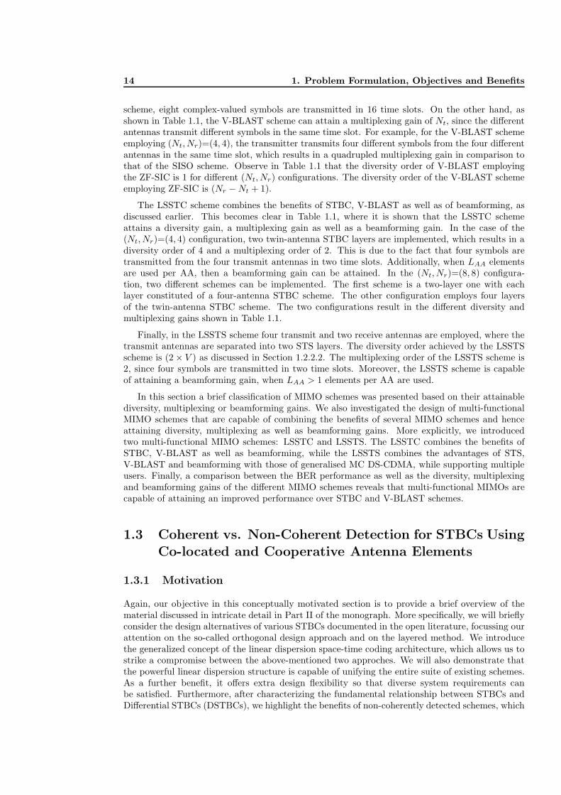
1.3.1 Motivation
Again, our objective in this conceptually motivated section is to provide a brief overview of thematerial discussed in intricate detail in Part II of the monograph. More specifically, we will brieflyconsider the design alternatives of various STBCs documented in the open literature, focussing ourattention on the so-called orthogonal design approach and on the layered method. We introducethe generalized concept of the linear dispersion space-time coding architecture, which allows us tostrike a compromise between the above-mentioned two approches. We will also demonstrate thatthe powerful linear dispersion structure is capable of unifying the entire suite of existing schemes.As a further benefit, it offers extra design flexibility so that diverse system requirements canbe satisfied. Furthermore, after characterizing the fundamental relationship between STBCs andDifferential STBCs (DSTBCs), we highlight the benefits of non-coherently detected schemes, which

1.3.2. Evolution of Space-Time Block Codes 15
are capable of exploiting the advantages of multiple antennas, while circumventing the potentiallyexcessive burden of multi-antenna channel estimation. Additionally, we will demonstrate thatthe linear dispersion structure can also be applied in systems, where the multiple-antenna arrayis formed in a distributed fashion by multiple single-antenna-aided cooperating mobile stations.Hence, the design of co-located and cooperative MIMO systems aiming for achieving diversity islinked from a linear dispersion perspective.
As argued above, apart from employing multiple antennas at the transmitter and receiver in a’co-located’ fashion, a Virtual Antenna Array (VAA) may also be formed by a group of cooperatingsingle-antenna-aided mobile stations. The resultant cooperative MIMO system is capable of offeringsimilar degrees of freedom to those of a co-located MIMO system having independently fading signalimpinging on the antenna elements. In other words, the distributed MIMO elements are capableof mimicking the functionality of the co-located MIMO elements.
The advantage of a MIMO system can be exploited in two ways: to increase the reliabilityof the system by providing a diversity gain [24] and/or to increase the data rate by providingmultiplexing gain [24]. In fact, it has been shown that there is a fundamental tradeoff between theachievable diversity gain and the attainable multiplexing gain for a given MIMO system [24]. Theterm spatial multiplexing gain refers to the fact that one can use multiple antennas to achieve ahigher throughput at the cost of an increased SNR requirement. On the other hand, the concept ofspatial diversity is to provide multiple independently fading replicas of the transmitted signal forthe receiver with the aid of the MIMO channel. If indeed these replicas are faded independently,it is unlikely that all copies of the transmitted signal are in a deep fade simultaneously. Therefore,the receiver is expected to reliably decode the transmitted signal using these independently fadedreceived signals. Finally, apart from the ’spatial’ dimension, diversity can also be achieved in boththe temporal as well as the frequency domains.
In many practical scenarios, reliable wireless communications may not be guaranteed, evenwhen multiple antennas have been employed. For example, when large-scale shadow fading con-taminates the wireless links, all the channels tend to fade together rather than independently,hence eroding the achievable diversity gain. Therefore, the concept of ’cooperative diversity’ [25]has been proposed in the literature, which is a technique designed for providing diversity using thesingle antennas of other nodes in the cellular network as ’virtual’ antennas.
In this section the design philosophies of spatial-diversity-oriented Space-Time Block Codes(STBCs) designed for open-loop MIMO systems are presented from a unique linear dispersionperspective. More explicitly, Section 1.3.2 demonstrates various design guidelines of STBCs andpresents a general framework to unify all the existing coherently detected STBCs found in theopen literature. Section 1.3.3 exploits the linkage between coherently detected STBCs and non-coherently detected STBCs having no Channel State Information (CSI), which enables our generalframework to incorporate the subclass of differential encoding/decoding techniques. Similarly, Sec-tion 1.3.4 examines the fundamental linkage between co-located and cooperative MIMO systems.Hence, cooperative STBCs can be created by applying the general linear dispersion framework.The expected performance is illustrated in Section 1.3.5, along with the related brief conclusions.
1.3.2 Evolution of Space-Time Block Codes
In order to exploit both the spatial as well as temporal domains offered by a MIMO system, STBCstransmit a signal matrix S conveying the source information. For a MIMO system having Mtransmit and N receive antennas, a STBC scheme can be designed to transmit Q symbols using Tchannel slots. The STBC scheme may be described by the parameter combination (MNTQ) havingthe normalized throughput of R = Q/T . In other words, the concept of STBCs is to design a setof matrices S satisfying both the throughput as well as diversity order requirements under certaincomplexity constraints. However, the number of matrices to be designed may become excessive,when the system is operating at a high normalized throughput facilitated by a high number of

16 1. Problem Formulation, Objectives and Benefits
antennas. This challenge was mainly addressed from two perspectives in the open literature,namely from the orthogonal and the layered approaches, both of which will be highlighted below.
1.3.2.1 Orthogonal Approach
The ’orthogonal’ approach was first proposed in [10], which was later generalized in [26]. Thephilosophy behind Orthogonal STBCs (OSTBCs) is that the space-time signal matrix S has to bean orthogonal/unitary matrix, where the orthogonality embedded in S is capable of decouplingthe transmitted multi-antenna-coded symbol streams into independent single-antenna symbols.For example, Alamouti’s scheme [10] can be characterized as follows:
G2 =
(s1 s2
−s∗2 s∗1
). (1.1)
Although the associated single-stream decoding procedure is appealing, the orthogonality of themulti-antenna streams limits the choice of modulation schemes and restricts the antenna config-urations supported. Hence, the OSTBCs are unable to reach a high normalized throughput. Onthe other hand, when relaxing the above-mentioned orthogonality of the OSTBCs, a potentiallyhigher normalized throughput can be achieved, as exemplified by the family of Quasi-OrthogonalSTBCs (QOSTBCs) [15].
Furthermore, the design of OSTBCs involves the inevitable throughput versus diversity gaintradeoff characterized in [27]. This is because each spatial and temporal slot is used to convey eithera new symbol to increase the throughput or a redundant symbol to attain diversity. However, withthe aid of the recent advances in high-throughput full-diversity 1 STBCs [28], it has been shownthat it is not necessary to sacrifice the throughput in favor of achieving diversity or vice versa.The philosophy of these schemes is that they impose redundancy on the space-time codeword, butadditional diversity gain can be achieved by spreading the information across both the spatial andtemporal domains. We will elaborate on this idea in more detail using Linear Dispersion Codes(LDCs) [28] [29] in Section 1.3.2.3.
1.3.2.2 Layered Approach
The motivation of introducing a ’layered’ structure into the STBCs is that of supporting high-throughput communications, as exemplified by schemes such as Bell Labs’ Layered-Space-Time(BLAST) architecture [16]. Although conventional BLAST-type schemes were not designed forachieving diversity, they provide a new insightful angle for STBC designs. For example, the G2
STBC of Equation (1.1) can be considered as a scheme consisting two layers. The first layeronly conveys the information symbol s1, which is ’repetition-coded’ and mapped to one of thediagonals of Equation (1.1). The second layer contains the symbol s2, which is mapped to theother diagonal of Equation (1.1). Each layer occupies half of the four spatial and temporal slotsand the inherent orthogonality enables the receiver to separate the two layers to facilitate sim-ple single-layer decoding. Since having more layers has the promise of an increased normalizedthroughput, the question of how many layers can a STBC codeword accommodate arises. In theliterature, the authors of [30] proposed a class of STBCs employing a unitary Time Variant LinearTransformation (TVLT), which is capable of transmitting using T layers, while maintaining a nor-malized throughput of R = M . Furthermore, high-throughput Threaded Algebraic Space-TimeBlock Codes (TASTBCs) [31] were proposed in order to support up to M number of adaptivelyreconfigurable layers. One of the intriguing features of both TVLTs and TASTBCs is that both ofthem are capable of achieving the full attainable spatial diversity order of MN , while maintaininga high throughput. This is guaranteed by mapping the signals of each layer across all the antennas,
1Using the average pairwise symbol error probability analysis technique [26], it follows that the maximum at-tainable diversity order of a STBC scheme designed for an (M × N)-element MIMO system is Dfull = MN .

1.3.2. Evolution of Space-Time Block Codes 17
+ +
AQ
s1sQ ]T
A1
T temporal dimensions
= [
dimensionsspatialM
S =∑Q
q=1 Aqsq =
K
Figure 1.6: The space-time codeword S employing the linear dispersion structure.
in order to achieve spatial diversity, as exemplified in Equation (1.1). Again, this philosophy willbe further augmented using the linear dispersion structure below.
1.3.2.3 Linear Dispersion Codes
At this stage of our discussions, the challenge of STBC design becomes that of finding an ap-propriate way of relaxing the orthogonality, while maintaining the maximum diversity order ofMN . Alternatively, we may cast this design dilemma as contriving a ’layered’ structure capableof exploiting all the spatial and temporal diversity resources available for a single layer, whilesupporting multiple layers. Remarkably, these design objectives may be satisfied by the familyof LDCs proposed by Hochwald and Hassibi [29]. The revolutionary concept of LDCs [28] [29]invokes a matrix-based linear modulation framework, where each space-time transmission matrixS is generated by a linear combination of so-called dispersion matrices and the weights of thecomponents are determined by the associated transmitted symbol vector. More explicitly, givenan information symbol vector K = [s1, s2, . . . , sQ]T constituted by symbols of an arbitrary modu-
lation constellation, the transmitted space-time matrix S may be defined as [28] S =∑Q
q=1 Aqsq,where each symbol sq is dispersed to the M spatial- and T temporal dimensions using a specificdispersion matrix Aq ∈ ζM×T and S is attained by the linear combination of all the weighteddispersion matrices. The schematic of the LDCs is specifically visualized in Figure 7.4.
Hence, it is beneficial to revisit the OSTBCs of Section 1.3.2.1 using the linear dispersionstructure of Figure 1.6. More explicitly, if each individual dispersion matrix Aq is an orthogonalmatrix and the set of dispersion matrices are orthogonal to each other, the resultant space-timecodeword S has to be an orthogonal/unitary matrix achieving full diversity [32]. This designphilosophy is that of the family of Linear STBCs (LSTBCs) [32]. Furthermore, by appropriatelychoosing the set of dispersion matrices depicted in Figure 1.6, the degree of orthogonality can beadjusted, leading to an increased design flexibility.
When compared to the layered STBCs discussed in Section 1.3.2.2, the LDCs of Figure 1.6consist of Q layers corresponding to the number of symbols transmitted per space-time block.Since the parameter Q is unrestricted, LDCs are capable of supporting an arbitrary number oflayers. Furthermore, rather than using only some of the (M × T ) slots available, each layer ofthe LDCs spans all the dimensions available, resulting in a high number of legitimate dispersionmatrices. However, it may not be feasible to perfectly separate the high number of superimposedlayers, unless sophisticated multi-stream receivers are used.
In summary, the LDCs of Figure 1.6 subsume all the above-mentioned space-time block codesexhibiting diverse characteristics by simply employing different sets of dispersion matrices. Hence,the LDCs provide a natural framework for satisfying diverse design criteria. Below, we offer arange of further remarks concerning LDCs.

18 1. Problem Formulation, Objectives and Benefits
• LDCs are suitable for arbitrary transmit and receive antenna configurations, combined witharbitrary modulation schemes;
• The maximum achievable diversity order of an LDC scheme is N · min(M, T ). This impliesthat increasing T beyond M does not provide any further advantage in terms of an increaseddiversity, whereas having T < M could decrease the maximum achievable spatial diversityorder. As expected, the receive diversity order is determined by the number of receiveantennas N alone. For the proof of the theorem please refer to [28].
• Every transmitted signal launched from each antenna is the linear combination of all theinformation symbols weighted by a set of dispersion matrices of Figure 1.6, which ensuresthat different replicas of the same information symbol are attainable. In other words, LDCsdemonstrate that spatial diversity can also be achieved without transmitting redundant in-formation at the cost of reducing the normalized throughput R.
• All the dispersion matrices Aq of Figure 1.6 can be described with the aid of the a singleDispersion Character Matrix (DCM) χ specified by χ = [vec(A1), vec(A2), . . . , vec(AQ)],where the vec() operation represents the vertical stacking of the columns of an arbitrarymatrix. The benefit of using a single DCM is that there is no need to design Q number ofseparate dispersion matrices.
• The linear nature of Figure 1.6 enables the receiver to recover the source information, pro-vided that the CSI is perfectly known at the receiver.
As far as the design of the set of dispersion matrices or the DCM is concerned, in their originalform, the LDCs [29] were optimized to maximize the ergodic capacity. In practice, the channel’sinput is constituted by non-Gaussian symbols, such as discrete-amplitude PSK and QAM signals,where a Discrete-input Continuous-output Memoryless Channel (DCMC) is encountered. There-fore, the more pertinent DCMC capacity is employed to optimize the LDCs [33]. Naturally, otheroptimization criteria can also be imposed on the DCM. For example, the authors of [28] specificallydesigned the LDCs to maximize the ergodic capacity, while maintaining a low BER. On the otherhand, LDCs can also be optimized using the so-called determinant criterion [26], where having anon-vanishing determinant is guaranteed.
1.3.3 Differential STBCs Using Colocated Antenna Elements
The primary focus of the codes discussed in Section 1.3.2 has been the case, where the receiver hasthe knowledge of the CSI. In practice, the knowledge of the CSI is typically acquired using a channelsounding sequence, which has an exponentially increasing complexity as a function of the numberof antennas. Furthermore, the relative frequency of estimating the channel has to be increasedproportionately to the Doppler frequency. Finally, an excessive number of training symbols maybe required. Hence, precious transmit power as well as valuable bandwidth are wasted. Therefore,differentially encoded low-complexity schemes, dispensing with pilot-based channel estimation andinvoking non-coherent detection became attractive.
The conventional Differential PSK (DPSK) designed for single antenna aided systems differen-tially encodes the information between successive transmission symbols, thus the information canbe recovered without the knowledge of the CSI, provided that the CSI does not change substantiallybetween them. A DPSK scheme is constituted by the serial concatenation of a PSK modulatorand a differential encoder. Here, we extend this philosophy to multiple antenna aided systems andthe schematic of the resultant Differential STBC (DSTBC) system is portrayed in Figure 1.7.
More explicitly, the ’space-time mapper’ of Figure 1.7 maps the n-th differentially encodedtransmission matrix Sn to all the spatial and temporal slots, whereas the ’differential encoder’ ofFigure 1.7 correlates the consecutive transmission matrices by Sn = Sn−1 · Xn, where Xn is the

1.3.3. Differential STBCs Using Colocated Antenna Elements 19
Space−Time
Coding
DetectorML
TransformCayley
Delay
Space−Time
Mapper
Differential Encoder
Mapper
PAM
Space−Time
Demapper Decoding
PAM
Q symbols
Sn−1
MXn
Kn = [s1n, · · · , s
Qn ]T︸ ︷︷ ︸ Xn Sn
N
Yn
Kn Xn
Figure 1.7: Schematic of a DLDC(MNTQ) scheme equipped with M transmit and N receive antennasand employing the Cayley transform, while transmitting Q symbols over T time slots usingSn.
space-time coded information matrix. Furthermore, this differential encoding process restricts theset of matrices Xn to be unitary, otherwise, the product Sn = XnXn−1 · · ·X1 may become zero,infinity, or both in different spatial and temporal directions. In other words, the challenge ofdesigning DSTBCs can be described as that of designing a family of STBCs, whereall the space-time matrices Xn are unitary.
Recall that the OSTBCs detailed in Section 1.3.2.1 generate orthogonal/unitary matrices bydefault, hence they become natural candidates for employment in DSTBC designs. Since the LDCsexhibit a high design flexibility as demonstrated in Section 1.3.2.3, it is desirable to retain the lineardispersion architecture in the differential design. Hence, the ’space-time encoding’ block of Fig-ure 1.7 is configured to generate space-time codewords Xn obeying the linear dispersion structureof Figure (1.6). However, even if each individual dispersion matrix is a unitary matrix, there isno guarantee that their weighted sum Xn will automatically become a unitary matrix. Hence, the’Cayley transform’ [13] block of Figure 1.7 is introduced in order to provide an efficient way ofprojecting the linearly-structured matrix Xn into a unique unitary matrix Xn, which potentiallyfacilitates the differential encoding of Figure 1.7. Apart from its additional computational com-plexity, the Cayley transform requires the employment of real-valued modulation schemes in orderto generate the unitary matrices. Also note that the DSTBCs typically suffer from a 3dB penaltyin comparison to the STBCs having perfect CSI, owing to the doubled equivalent channel noiseencountered during the detection.
In summary, the design of DSTBCs based on coherently detected STBCs is facilitated by the’unitary’ constraint. Furthermore, the philosophy of LDCs may be extended to the differentialencoding domain and the resultant Differential Linear Dispersion Codes (DLDCs) based on theCayley transform [34] provide a general framework for DSTBCs. Consequently, DLDCs are capableof supporting arbitrary antenna configurations as well as a dynamically reconfigurable throughput.Similarly to LDCs, all the dispersion matrices of a DLDC scheme can be characterized by a singleDCM. On the other hand, the performance of DLDCs is affected by the rate of Doppler-inducedchannel fluctuations.

20 1. Problem Formulation, Objectives and Benefits
1.3.4 Cooperative STBCs Using Distributed Antenna Elements
The STBC techniques detailed in Sections 1.3.2 and 1.3.3 provide promising solutions in the contextof co-located MIMO systems requiring reliable wireless communications at high rates. However,it may not always be practical to accommodate multiple antennas at the mobile stations, owingto cost, size and other hardware limitations. A further limitation of having co-located MIMOelements is that even at relatively large element separations their elements may not benefit fromindependent fading, when subjected to shadow-fading imposed for example by large-bodied vehiclesor other shadowing local paraphernalia. As a remedy, the concept of cooperative MIMOs have beenproposed for cellular systems as an attempt to attain a better communication efficiency beyondthat permitted by a single node’s resources. More specifically, a group of mobile nodes, known asrelays, ’shares’ their antennas with other users to create a VAA to provide spatial diversity gain.
Owing to the philosophical similarities between the cooperative MIMO and the co-locatedMIMO systems, numerous space-time block coding techniques have been ’transplanted’ into relay-aided schemes in order to achieve cooperative diversity, based on either Amplify-and-Forward (AF)strategies or Decode-and-Forward (DF) arrangements. It was Laneman and Wornell [25] who firstproposed to employ OSTBCs for cooperative MIMO systems, where each relay transmits accordingto a different column of the orthogonal STBC matrix. In this section, we focus our attention onthe employment of the LDC structure in the context of cooperative MIMO systems, namely intwin-layer Cooperative LDCs (CLDCs).
Figure 1.8 portrays the schematic of the cooperation-aided UpLink (UL) system using theabove-mentioned twin-layer CLDC. As seen in Figure 1.8, each transmission block consists of twointervals, namely the broadcast interval of duration T1 and the cooperation interval of length T2.This scheme supports the cooperation of M number of relays transmitting Q information symbolsper block to the base station equipped with N receive antennas, provided that the total numberof channel uses T obeys T = T1 + T2.
The assumptions and the rationale of this model are summarized as follows:
• All the relays of Figure 1.8 are assumed to transmit synchronously. Quasi-synchronous trans-missions can be accomplished, when the relative delays between the relays are significantlyshorter than the symbol duration;
• All the nodes of Figure 1.8 are assumed to have a single antenna and hence operate inhalf-duplex mode, i.e. at any point of time, a node can either transmit or receive. Thisconstraint is imposed, in order to prevent the high-power transmit signal from contaminatingthe low-power received signal, for example, by the non-linear distortion-induced out-of-boundemissions routinely encountered at the transmitter.
• All the relays of Figure 1.8 transmit and receive on the same frequency as the source node,in order to avoid wasting or occupying additional bandwidth;
• No communication is permitted between the relays, in an effort to minimize the total networktraffic. The relays may use the same previously unallocated time-slot for their reception andtransmission;
• Since the simple AF strategy is adopted, only linear combination operations are performedat the relays before retransmitting the signals dispersed to the cooperating MIMO elementsto the BS;
• We confine the total number of channel uses of the twin-layer CLDC scheme of Figure 1.8 toT . Hence, by appropriately adjusting the parameters T1 or T2, different degrees of freedomcan be provided for the broadcast interval as well as for the cooperation interval;
• At any given time, the total transmit power of the twin-layer CLDC scheme of Figure 1.8 isnormalized to unity.

1.3.4. Cooperative STBCs Using Distributed Antenna Elements 21
N receive antennas
+T =
Twin−Layer CLDC(MNTQ)
Source Node
R1
RM
︸ ︷︷ ︸
Y
︸ ︷︷ ︸
K = [s1, · · · , sQ︸ ︷︷ ︸Q
]T
Base Station having
Broadcast Interval (T1)
M number of Relays
Cooperation Interval (T2)
Z1
ZM
S1 H1 S2 H2
++T2
θ[
++T2
θ[ r21
ZM
r1M r2
MθRM =
The M -th Relay
The 1st Relay
z11
z12......
z1T2
︸ ︷︷ ︸
=
zM1
zM2......
zMT2
︸ ︷︷ ︸
=
Z1
r11θR1 = r
T1
1 ]T
rT1
M ]T
B1
BM
S2 =
ZT1...
ZTM
Figure 1.8: Schematic of the cooperation-aided uplink system employing twin-layer Cooperative LinearDispersion Codes (CLDCs).

22 1. Problem Formulation, Objectives and Benefits
During the broadcast interval T1, the first-layer dispersion matrix χ1 is responsible for dispersingthe source information vector K = [s1, . . . , sQ]T to all the T1 temporal slots. The resultantspace-time codeword S1 of Figure 1.8 is transmitted through independent source-to-relay Rayleighfading channels. The received signal vector of the m-th relay is Rm. During the cooperationinterval T2, the relays form a VAA and cooperatively transmit the space-time codeword S2 ofFigure 1.8 to the BS based on CLDC’s second-layer dispersion matrix. More explicitly, the processof forming the cooperative space-time codeword S2 for the cooperation interval is also visualized inFigure 1.8. Each relay contributes one row of the cooperative space-time codeword S2 by dispersingthe corresponding normalized received signal vector θRm = θ[r1
m, . . . , rT1m ]T to the available T2
temporal slots using the pre-assigned dispersion matrix. Again, the dispersion matrices fromall the relays can be characterized by a single DCM χ2. Hence, the receiver can recover thesource information by exploiting the linearity of the CLDCs, provided that the CSI as well asthe dispersion matrices χ1 and χ2 are known at the receiver. Since only T2 time slots are usedfor achieving cooperative diversity and the relays only have access to the noisy version of thetransmitted information, the maximum achievable diversity order of the CLDCs becomes D ≈N · min(M, T2).
Hence, we conclude that the fundamental difference between cooperative and co-located MIMOsystems is the existence of the broadcast interval, which is used by the relays to attain preferablyperfect but typically imperfect source information, depending on the specific cooperation strategyemployed. As a result, instead of employing a single DCM as in the LDC scheme, the CLDCscheme requires a pair of DCMs (χ1, χ2) in order to characterize the transmission regime of boththe broadcast interval and of the cooperation interval, respectively.
1.3.5 Performance for Imperfect Channel Estimates and Shadow-Fading
In this section, we provide a set of comparisons between the family of LDCs, DLDCs and CLDCsin order to evaluate their advantages as well as limitations, when communicating in small -scale orlarge-scale fading scenarios as well as when having perfect or imperfect CSI at the receiver. Allthe simulation parameters were listed in Table 1.2. Observe in Table 1.2 that we set M = T andassume that the channels were subjected to Rayleigh fading having fd = 10−2 in order to enable theadequate operation of the DLDCs based on the Cayley transform. Hence, the group of LDCs andDLDCs have the potential to achieve the full attainable diversity order of D = N ·min(M, T ) [28]in comparison to the reduced maximum diversity order D ≈ N · min(M, T2) of the CLDCs.
For Comparison A of Table 1.2, Figure 1.9 characterizes the achievable throughput of the groupof LDCs, DLDCs and CLDCs recorded at BER=10−4, when the wireless channels were subjectedto small -scale Rayleigh fading and perfect CSI was available at the receiver. Observe in Figure 1.9that the class of LDCs is capable of operating at the lowest SNR at a certain throughput. Thegroup of DLDCs suffers from the usual 3dB SNR penalty in comparison to that of the LDCs, sinceno CSI was exploited. The family of CLDCs operates at SNRs further away from that of the LDCs,owing to their reduced achievable diversity order as well as due to having the noisy rather thanperfect version of the source information.
For Comparison B of Table 1.2, Figure 1.10 characterizes the effective throughput of the LDCs,the DLDCs and the CLDCs of Table 1.2 recorded at BER=10−4, when the wireless channelswere subjected to small -scale Rayleigh fading and the receiver has imperfect CSI. We assumethat the channel estimation errors obey the Gaussian distribution and the degree of the CSIestimation errors is governed by the ratio ω (dB) with respect to the received signal power. Hence,the perfect CSI scenario corresponds to ω = −∞. Observe in Figure 1.10 that the family ofDLDCs demonstrated a significant advantage over the LDCs at a high throughput, even whenthe channel estimation errors were as low as ω = −10dB. Since the group of CLDCs has an errorfloor higher than BER=10−4, the associated throughput curve was omitted from Figure 1.10. Thisphenomenon suggested that the CLDCs are more sensitive to the channel estimation errors than

1.3.5. Performance for Imperfect Channel Estimates and Shadow-Fading 23
Table 1.2: Comparison of the LDCs of Section 1.3.2.3, the DLDCs of Section 1.3.3 and the CLDCs ofSection 1.3.4, when communicating over small-scale/large-scale fading channels and havingperfect/imperfect CSI at the receiver.
LDC DLDC CLDCM 3 3 3N 2 2 2T 3 3 T1 = 1, T2 = 2Q 1,2,3 1,2,3 1,2,3Modulation BPSK BPSK BPSKMapping Gray mapping Gray mapping Gray mappingDetector ML ML MLDoppler frequency fd = 10−2 fd = 10−2 fd = 10−2
Diversity D = 6 D = 6 D ≈ 4Comparison A Small -scale Rayleigh fading, perfect CSI in Figure 1.9Comparison B Small -scale Rayleigh fading, imperfect CSI in Figure 1.10Comparison C Large-scale shadowing, perfect CSI in Figure 1.11
0 5 10 15 20 25 30 35 400
0.2
0.4
0.6
0.8
1
1.2
SNR or ρRB
(dB)
Effe
ctiv
e th
roug
hput
(bi
ts/s
ym/H
z)
LDC(323Q)DLDC(323Q)CLDC(323Q)
Figure 1.9: Throughput comparison for the LDCs of Section 1.3.2.3, the DLDCs of Section 1.3.3 andthe CLDCs of Section 1.3.4 recorded at BER=10−4, when communicating over small -scaleRayleigh fading channels and assuming that the perfect CSI was known by the receiver. Allthe system parameters were summarized in Table 1.2.

24 1. Problem Formulation, Objectives and Benefits
0 5 10 15 20 25 30 35 400
0.2
0.4
0.6
0.8
1
1.2
SNR (dB)
Effe
ctiv
e th
roug
hput
(bi
ts/s
ym/H
z)
LDC(323Q), ω = −10dBLDC(323Q), ω = −9dBDLDC(323Q)
Figure 1.10: Throughput comparison for the LDCs of Section 1.3.2.3, the DLDCs of Section 1.3.3 andthe CLDCs of Section 1.3.4 recorded at BER=10−4, when communicating over small -scaleRayleigh fading channels and having imperfect CSI governed by ω (dB). All the systemparameters were summarized in Table 1.2.
0 5 10 15 20 25 30 35 400
0.2
0.4
0.6
0.8
1
1.2
SNR or ρRB
(dB)
Effe
ctiv
e th
roug
hput
(bi
ts/s
ym/H
z)
LDC(323Q), shadowing with Ω=6dBDLDC(323Q), shadowing with Ω=6dBCLDC(323Q), no shadow fading
Figure 1.11: Throughput comparison for the LDCs of Section 1.3.2.3, the DLDCs of Section 1.3.3 andthe CLDCs of Section 1.3.4 recorded at BER=10−4, when the channels were subjected tolarge-scale shadowing and assuming that the perfect CSI was known at the receiver. All thesystem parameters were summarized in Table 1.2.

1.4. Historic Perspective and Sate-of-the-art Contributions 25
the LDCs. This is because the CLDCs require the CSI knowledge of both the source-to-relayand the relay-to-destination channels in comparison to the classic single-phase direct transmissionregime of co-located MIMO systems.
Finally, in Comparison C of Table 1.2, Figure 1.11 characterizes the throughput of the LDCs,the DLDCs and the CLDCs of Table 1.2 recorded at BER=10−4, when the communication channelswere subjected to shadowing and the receiver had access to perfect CSI. The shadow fading effectwas assumed to have log-normal distribution and was governed by a random Gaussian variablehaving zero mean and a standard deviation of Ω (dB). Observe in Figure 1.11 that the familyof CLDCs designed for the cooperative MIMO systems has the best ability to combat the effectof large-scale shadowing with the aid of relays. Compared to the small-scale Rayleigh fadingperformance curves of Figure 1.9, the SNR required for the group of LDCs in Table 1.2 to maintaina BER of 10−4 increased by about 17dB, even though the receiver had access to perfect CSI.
Again, our investigations indicate that the LDCs obeying the structure of Figure 1.6 are idealfor small-scale fading environments, when near-perfect CSI is available. On the other hand, theDLDCs having the structure of Figure 1.7 constitute the most appropriate solution, when theCSI is unavailable or the channel estimation would impose severe errors. Finally, when large-scaleshadowing dominates the achievable performance, the family of CLDCs obeying the structure ofFigure 1.8 remains capable of maintaining reliable wireless communications.
In conclusion of this brief section, the design guidelines of diverse STBCs schemes found inthe open literature were considered. More explicitly, we demonstrated that the linear dispersionstructure unifies the orthogonal approach as well as the layered architecture. The flexibility of theLDCs allows them to be designed according to diverse constraints and to be adopted to variousMIMO scenarios. Furthermore, the linkage between STBCs and DSTBCs may be established withthe aid of the ’unitary’ constraint, which enables us to invoke the LDC structure also in the dif-ferential encoding domain. In the case of cooperative MIMO systems, the flexible linear structureremains applicable, but an additional dipersion character matrix is required to characterize thetransmissions during the broadcast interval. Finally, the rudimentary performance results pro-vided explicitly demonstrated the suitable application scenarios for the various LDCs, DLDCs andCLDCs considered.
1.4 Historic Perspective and Sate-of-the-art Contributions
1.4.1 Colocated MIMO Techniques
MIMO systems exhibit higher capacity than single-antenna-aided systems. Multiple antennas canbe used to provide diversity gains and hence a better BER performance or multiplexing gains, inorder to attain a higher throughput. Additionally, multiple antennas can be used at the transmitteror receiver in order to attain a beamforming gain. On the other hand, multiple antennas can beemployed in order to attain diversity gains, multiplexing gains as well as beamforming gains asshown in Figure 1.2. The terminology of colocated MIMOs refers to the systems, where the multipleantennas are located at the same transmitter or receiver station. In the sequel, we give an overviewof the family of multiple antennas, when used for achieving diversity, multiplexing or beamforminggains.
1.4.1.1 Diversity Techniques
Communication in the presence of channel fading has been one of the grand research challenges inrecent times. In a fading channel, the associated severe attenuation often result in decoding errors.A natural way of overcoming this problem is to allow the receiver to have several replicas of thesame transmitted signal, while assuming that at least some of them are not severely attenuated.

26 1. Problem Formulation, Objectives and Benefits
Year Author(s) Contribution
1959 Brennan [35] introduced and provided analysis for the three combining tech-niques: selection combining, maximum ratio combining and equalgain combining.
1991 Wittneben [36] proposed a bandwidth-efficient transmit diversity technique,where different base stations transmit the same signal.
1993 Wittneben [37] proposed a modulation diversity scheme in a system equipped withmultiple transmit antennas.
Seshadri et al. [38] proposed a transmit diversity scheme that was inspired by thedelay diversity design of Wittneben [37].
1994 Winters [39] proved that the diversity advantage of the scheme proposed in [36]is equal to the number of transmit antennas.
1996 Eng et al. [40] Compared several diversity combining techniques in a Rayleighfading transmission with coherent detection and proposed a newsecond order selection combining technique.
1998 Alamouti [10] discovered a transmit diversity scheme using two transmit anten-nas with simple linear processing at the receiver.
Tarokh et al. [12] proposed a complete study of design criteria for maximum diver-sity and coding gains in addition to the design of space-time trelliscodes.
1999 Tarokh et al. [11,26]
generalised Alamouti’s diversity scheme [10] to more than twotransmit antennas.
Guey [41] derived the criterion for designing the maximum transmit diversitygain.
2001 Hochwald et al. [14] proposed the twin-antenna-aided space-time spreading scheme.Jafarkhani etal. [15]
designed rate-one STBC codes which are quasi-orthogonal andprovide partial diversity gain.
2002 Hassibi et al. [13] proposed the LDCs that provide a flexible trade-off between space-time coding and spatial multiplexing.
Stoica et al. [42] compared the performance of STBC when employing differentestimation/detection techniques and proposed a blind detectionscheme dispensing with the pilot symbols transmission for chan-nel estimation.
Table 1.3: Major coherent spatial diversity techniques (Part 1).
This technique is referred to as diversity, where it is possible to attain diversity gains by creatingindependently fading signal replicas in the time, frequency or spatial domain.
Spatial diversity can be attained by employing multiple antennas at the transmitter or thereceiver. Multiple antennas can be used to transmit and receive the same information sequence inorder to achieve diversity and hence to obtain an improved BER performance. A simple spatialdiversity technique, which does not involve any loss of bandwidth, is constituted by the employmentof multiple antennas at the receiver. In case of narrowband frequency-flat fading, the optimumcombining strategy in terms of maximising the SNR at the combiner output is Maximum RatioCombining (MRC) [9, 35, 43]. Additionally, other combining techniques have been proposed inthe literature, as shown in Figure 1.2, including Equal Gain Combining (EGC) [35] and SelectionCombining (SC) [9]. All the three combining techniques are said to achieve full diversity order,which is equal to the number of receive antennas [40].
On the other hand, the idea of transmit diversity corresponds to the transmission of the samesignal over multiple transmit antennas at the same time within the same bandwidth. The first

1.4.1. Colocated MIMO Techniques 27
Year Author(s) Contribution
2003 Wang et al. [44] derived upper bounds for the rates of complex orthogonal STBCs.Su et al. [45] introduced the concept of combining orthogonal STBC designs
with the principle of sphere packing.2005 Zhang et al. [46] derived the capacity and probability of error expressions for
PSK/PAM/QAM modulation with STBC for transmission overRayleigh-, Ricean- and Nakagami-fading channels.
2006 Liew et al. [47] studied the performance of STTC and STBC in the context ofwideband channels using adaptive orthogonal frequency divisionmultiplex modulation.
2007 Alamri et al. [48] modified the SP demapper of [45] for the sake of accepting thea priori information passed to it from the channel decoder asextrinsic information.
2008 Luo et al. [49] combined orthogonal STBCs with delay diversity and designedspecial symbol mappings for maximising the coding advantage.
Table 1.4: Major coherent spatial diversity techniques (Part 2).
bandwidth-efficient transmit diversity scheme was proposed in [36] and it was shown that the di-versity advantage of this scheme is equal to the number of transmit antennas [39, 50, 51]. In [10]Alamouti discovered a witty transmit diversity technique using two transmit antennas, whosekey advantage was the employment of simple linear processing at the receiver, which is based onMaximum-Likelihood (ML) detection. The decoding algorithm proposed in [10] can be generalisedto an arbitrary number of receive antennas using MRC, EGC or SC. Alamouti’s achievement in-spired Tarokh et al. [11,26] to generalise the transmit diversity scheme to more than two transmitantennas, contriving the concept of Space-Time Block Codes (STBC). The family of STBCs iscapable of attaining the same diversity gain as Space-Time Trellis Codes (STTC) [12,52] at lowerdecoding complexity, when employing the same number of transmit antennas. However, a disad-vantage of STBCs when compared to STTCs is that they provide no coding gain [9], as documentedfor example in [47].
Inspired by the philosophy of STBCs, Hochwald et al. [14] proposed the transmit diversity con-cept known as Space-Time Spreading (STS) for the downlink of Wideband Code Division MultipleAccess (WCDMA) [53] that is capable of achieving the highest possible transmit diversity gain.The STBC and STS designs contrived for higher number of transmit antennas results in a reductionof the achievable transmission rate and hence in a reduction of the attainable bandwidth efficiency.An alternative idea for constructing full-rate STBCs for complex modulation schemes and morethan two antennas was pursued in [15, 51]. Here the strict constraint of perfect orthogonality wasrelaxed in favour of a higher data rate. The resultant STBCs were referred to as quasi-orthogonalSTBCs [15].
The STBC and STS designs offer at best the same data rate as an uncoded single-antennasystem, but they provide an improved BER performance as compared to the family of single-antenna-aided systems by providing diversity gains. In contrast to this, several high-rate space-time transmission schemes having a normalised rate higher than one have been proposed in theliterature. For example, high-rate space-time codes that are linear in space and time, namely theso-called Linear Dispersion Codes (LDC), were proposed in [13]. LDCs provide a flexible trade-offbetween achieving space-time coding and spatial multiplexing.
Additionally, the concept of combining orthogonal transmit diversity designs with the principleof Sphere Packing (SP) was introduced by Su et al. [45] in order to maximise the achievable codingadvantage, where it was demonstrated that the proposed SP aided STBC scheme was capableof outperforming the conventional orthogonal design based STBC schemes of [10, 11]. A further
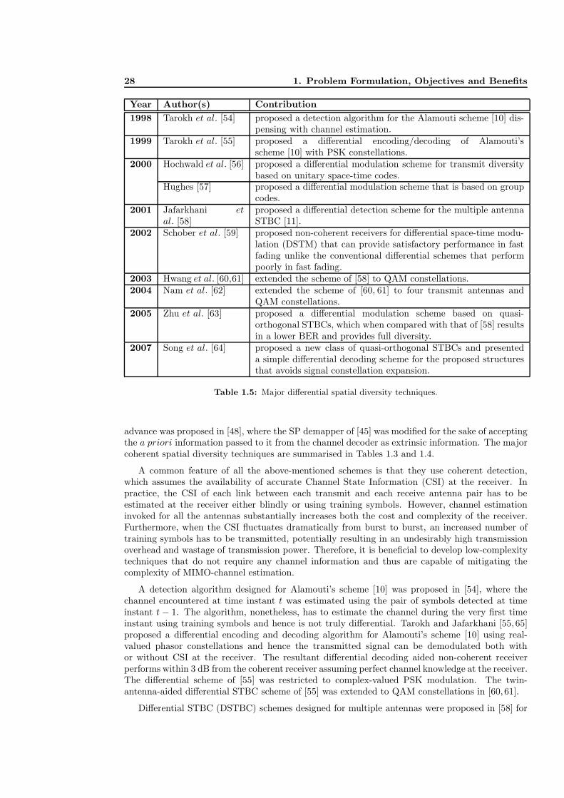
28 1. Problem Formulation, Objectives and Benefits
Year Author(s) Contribution
1998 Tarokh et al. [54] proposed a detection algorithm for the Alamouti scheme [10] dis-pensing with channel estimation.
1999 Tarokh et al. [55] proposed a differential encoding/decoding of Alamouti’sscheme [10] with PSK constellations.
2000 Hochwald et al. [56] proposed a differential modulation scheme for transmit diversitybased on unitary space-time codes.
Hughes [57] proposed a differential modulation scheme that is based on groupcodes.
2001 Jafarkhani etal. [58]
proposed a differential detection scheme for the multiple antennaSTBC [11].
2002 Schober et al. [59] proposed non-coherent receivers for differential space-time modu-lation (DSTM) that can provide satisfactory performance in fastfading unlike the conventional differential schemes that performpoorly in fast fading.
2003 Hwang et al. [60,61] extended the scheme of [58] to QAM constellations.2004 Nam et al. [62] extended the scheme of [60, 61] to four transmit antennas and
QAM constellations.2005 Zhu et al. [63] proposed a differential modulation scheme based on quasi-
orthogonal STBCs, which when compared with that of [58] resultsin a lower BER and provides full diversity.
2007 Song et al. [64] proposed a new class of quasi-orthogonal STBCs and presenteda simple differential decoding scheme for the proposed structuresthat avoids signal constellation expansion.
Table 1.5: Major differential spatial diversity techniques.
advance was proposed in [48], where the SP demapper of [45] was modified for the sake of acceptingthe a priori information passed to it from the channel decoder as extrinsic information. The majorcoherent spatial diversity techniques are summarised in Tables 1.3 and 1.4.
A common feature of all the above-mentioned schemes is that they use coherent detection,which assumes the availability of accurate Channel State Information (CSI) at the receiver. Inpractice, the CSI of each link between each transmit and each receive antenna pair has to beestimated at the receiver either blindly or using training symbols. However, channel estimationinvoked for all the antennas substantially increases both the cost and complexity of the receiver.Furthermore, when the CSI fluctuates dramatically from burst to burst, an increased number oftraining symbols has to be transmitted, potentially resulting in an undesirably high transmissionoverhead and wastage of transmission power. Therefore, it is beneficial to develop low-complexitytechniques that do not require any channel information and thus are capable of mitigating thecomplexity of MIMO-channel estimation.
A detection algorithm designed for Alamouti’s scheme [10] was proposed in [54], where thechannel encountered at time instant t was estimated using the pair of symbols detected at timeinstant t − 1. The algorithm, nonetheless, has to estimate the channel during the very first timeinstant using training symbols and hence is not truly differential. Tarokh and Jafarkhani [55, 65]proposed a differential encoding and decoding algorithm for Alamouti’s scheme [10] using real-valued phasor constellations and hence the transmitted signal can be demodulated both withor without CSI at the receiver. The resultant differential decoding aided non-coherent receiverperforms within 3 dB from the coherent receiver assuming perfect channel knowledge at the receiver.The differential scheme of [55] was restricted to complex-valued PSK modulation. The twin-antenna-aided differential STBC scheme of [55] was extended to QAM constellations in [60, 61].
Differential STBC (DSTBC) schemes designed for multiple antennas were proposed in [58] for

1.4.1. Colocated MIMO Techniques 29
real-valued constellations. Afterwards, the authors of [60, 62] developed a DSTBC scheme thatsupports non-constant modulus constellations combined with four transmit antennas. This exten-sion, however, requires the knowledge of the received power in order to appropriately normalise thereceived signal. The received power was estimated blindly using the received differentially encodedsignals without invoking any channel estimation techniques or transmitting any pilot symbols.In [56], a differential modulation scheme was proposed for the sake of attaining transmit diversitybased on unitary space-time codes [66]. The proposed scheme can be employed in conjunction withan arbitrary number of transmit antennas. Around the same time, a similar differential schemewas also proposed in [57] based on the employment of group codes.
Zhu et al. [63] proposed a differential modulation scheme based on quasi-orthogonal STBCs,which were compared to that of [58] and resulted in a reduced BER as a benefit of providingfull diversity. Additionally, a new class of quasi-orthogonal STBCs was proposed in [64], whichpresented a simple differential decoding scheme that avoids signal constellation expansion. Themajor contributions on differential spatial diversity techniques are summarised in Table 1.5.
1.4.1.2 Multiplexing Techniques
STBC and STTC are capable of providing diversity gains for the sake of improving the achievablesystem performance. However, this BER performance improvement is often achieved at the expenseof a rate loss since the STBC and STTC may result in a throughput loss compared to single-antenna-aided systems. As a design alternative, a specific class of MIMO systems was designed forimproving the attainable spectral efficiency of the system by transmitting the signals independentlyfrom each of the transmit antennas, hence resulting in a multiplexing gain.
The basic principle of spatial multiplexing can be summarised as follows. The source bit se-quence at the transmitter side is split into Nt sequences, which are modulated and then transmittedsimultaneously from the Nt transmit antennas using the same carrier frequency. At the receiverside, interference cancellation is employed in order to separate the different transmitted signals.In the case of narrowband frequency flat fading, there are several decoding algorithms designedfor interference cancellation at the receiver side of the spatial multiplexing systems. The differentreceivers can be characterised by a tradeoff between the achievable performance and the complexityimposed. A low-complexity receiver is constituted by the Zero-Forcing (ZF) or the Minimum MeanSquare Error (MMSE) technique [67,68]. However, when we employ the ZF receiver, the attainableBER performance is typically poor in addition to imposing the condition that the number of receiveantennas should be at least equal to the number of transmit antennas. The optimum receiver is theMaximum Likelihood (ML) receiver [69], which is capable of achieving full diversity gain, i.e. thesame diversity order, as the number of receive antennas. However, a major drawback of the MLreceiver is its complexity that grows exponentially with the number of transmit antennas and thenumber of bits per symbol employed by the modulation scheme. Fortunately, the complexity of theML decoders can be reduced by employing sphere decoders [70–72] that are capable of achievinga similar performance to the ML decoders at a fraction of their complexity.
In [73] Foschini proposed a multi-layer MIMO structure, known as the Diagonal Bell LabsLayered Space-Time (D-BLAST) scheme2, which is in principle capable of approaching the sub-stantial capacity of MIMO systems. The D-BLAST signal may be subjected to low-complexitylinear processing for decoding the received signals. However, the diagonal approach suffers from apotentially high implementation complexity that led Wolniansky et al. to propose another versionof BLAST, which is known as Vertical BLAST (V-BLAST) [16]. In V-BLAST, each transmitantenna simultaneously transmits independent data over the same carrier frequency band. At thereceiver side, provided that the number of receive antennas is higher than or equal to the number
2The diagonal approach implies that the signal mapped to the consecutive antenna elements is delayed in time,which has the potential of subjecting the delayed signal components of a space-time symbol to more independentfading, hence leading to a potential diversity gain.

30 1. Problem Formulation, Objectives and Benefits
Year Author(s) Contribution
1996 Foschini et al. [73] studied the encoding and decoding of the diagonal BLAST struc-ture.
1998 Wolniansky etal. [16]
introduced the vertical BLAST architecture for reducing the im-plementation complexity of the diagonal approach.
1999 Golden et al. [74] provided the first real-time BLAST demonstrations.2001 Benjebbour et
al. [75]introduced the minimum mean square error receiver for V-BLASTand introduced an ordering scheme for improving the attainableperformance.
2002 Sellathurai etal. [76]
studied the combination of BLAST architecture with that of aturbo code to improve its performance.
2003 Wubben et al. [77] proposed a detector for improving the attainable performance ofV-BLAST.
2004 Zhu et al. [78] proposed a complexity-reduction algorithm for BLAST detectors.2005 Huang et al. [79] proposed a new detection algorithm for BLAST based on the con-
cept of particle filtering and provided a near ML performance ata reasonable complexity.
Table 1.6: Major spatial multiplexing techniques.
of transmit antennas, a low complexity serial decoding algorithm may be applied to detect thetransmitted data. The V-BLAST transceiver is capable of providing a substantial increase of aspecific user’s effective bit-rate without the need for any increase in the transmitted power or thesystem’s bandwidth. However, its impediment is that it was not designed for exploiting transmitdiversity. Furthermore, the decision errors of a particular antenna’s detector propagate to otherbits of the multi-antenna symbol, when erroneously cancelling the effects of the sliced bits fromthe composite signal. The V-BLAST detector first selects the layer3 with the largest SNR andestimates the transmitted bits of that layer, while treating the other layers as interference. Thedetected symbol is then subtracted from the received signal and then the layer with the secondhighest SNR is selected for decoding. The procedure is repeated for all the layers. The BERperformance of each layer is different and it depends on the received SNR of each layer. The firstdecoded layer has the highest SNR, while the layers detected later have a higher diversity order,since they suffer from less interference.
The BLAST detection algorithm is based on Successive Interference Cancellation (SIC), whichwas originally proposed for multiuser detection in CDMA systems [80]. Several BLAST detectorshave been proposed in the literature for either reducing the complexity [81–86] or for improvingthe attainable BER performance [77, 87–92]. An alternative design approach contrived for spatialmultiplexing using less receive antennas than transmit antennas was proposed in [93] based on groupMaximum A Posteriori (MAP) detection. In [76, 94] a spatial multiplexing scheme referred to asTurbo-BLAST was proposed, which uses quasi-random interleaving in conjunction with an iterativereceiver structure, in order to separate the individual layers. The major spatial multiplexingtechniques are summarised in Table 1.6.
1.4.1.3 Beamforming Techniques
According to Sections 1.4.1.1 and 1.4.1.2, it becomes clear that multiple antennas can be usedfor the sake of attaining either spatial diversity or spatial multiplexing gains. However, multipleantennas can also be used in order to improve the Signal-to-Noise Ratio (SNR) at the receiver orthe Signal-to-Interference-plus-Noise Ratio (SINR) in a multi-user scenario. This can be achieved
3The layer in the case of the V-BLAST corresponds to each of the transmit antennas.

1.4.1. Colocated MIMO Techniques 31
by employing beamforming techniques [17, 95]. Beamforming constitutes an effective technique ofreducing the multiple access interference, where the antenna gain is increased in the direction ofthe desired user, whilst reducing the gain towards the interfering users.
In a wireless communications scenario the transmitted signals propagate via several paths andhence are received from different directions/phases at the receiver. If the directions of the differentpropagation paths are known at the transmitter or the receiver, then beamforming techniques canbe employed in order to direct the received beam pattern in the direction of the specified antennaor user [96, 97]. Hence, significant SNR gains can be achieved in comparison to a single antennasystem. On the transmitter side, when the Direction of Arrival (DOA) of the dominant paths atthe receiver is known for the transmitter, then the transmit power is concentrated in the directionof the target user, where less power is wasted in the other directions.
On the other hand, beamforming can be used in order to reduce the co-channel interferenceor multiuser interference. When using beamforming, each user adjusts his/her beam pattern toensure that there are nulls in the directions of the other users, while there is a high directivity inthe direction of the desired receiver [17, 98]. Hence, the system attains an SINR gain.
1.4.1.4 Multi-functional MIMO Techniques
V-BLAST is capable of achieving full multiplexing gain, while STBC can achieve full antennadiversity gain. Hence, it was proposed in [18] to combine the two techniques to provide bothantenna diversity and spectral efficiency gains. More specifically, it was proposed that the antennasat the transmitter be partitioned into layers, where each layer uses STBC. At the receiver side,successive group interference cancellation can be applied to each layer before decoding the signalsusing ML STBC decoding. Therefore, by combining V-BLAST and STBC, an improved transmitdiversity gain can be achieved as compared to pure V-BLAST, while ensuring that the overallbandwidth efficiency is higher than that of pure STBC due to the independence of the signalstransmitted by different STBC layers. Furthermore, the combined array processing proposedin [18] was improved in [19] by optimising the decoding order of the different antenna layers. Aniterative decoding algorithm was proposed in [19] that results in a full receive diversity gain forthe combined V-BLAST STBC system.
In [20] the authors presented a transmission scheme referred to as Double Space-Time TransmitDiversity (D-STTD), which consists of two STBC layers at the transmitter that is equipped withfour transmit antennas, while the receiver is equipped with two antennas. The decoding of D-STTDpresented in [20] is based on a linear decoding scheme presented in [110], where the authors provideda broad overview of space-time coding and signal processing designed for high data rate wirelesscommunications. A two-user scheme was presented in [110], where each user is equipped with atwin-antenna-aided STBC scheme transmitting at the same carrier frequency and in the same timeslot. A two-antenna-aided receiver was implemented for the sake of decoding the two users’ data,while eliminating the interference imposed by the users on each others’ data. An extension tothe idea of combining interference cancellation with STBC techniques was presented in [100,102],where the STBC and interference cancellation arrangements were combined with CDMA for thesake of increasing the number of users supported by the system. A zero-forcing decoder designedfor the D-STTD was presented in [107] for the sake of reducing the decoding complexity. Finally,the authors of [101, 111] presented further results that compare the performance of STBC versusD-STTD and extended the applicability of the D-STTD scheme to more than two STBC layers.
Furthermore, in order to achieve additional performance gains, beamforming has been combinedwith spatial diversity as well as spatial multiplexing techniques. STBC has been combined withbeamforming in order to attain a higher SNR gain in addition to the diversity gain [21, 104, 105,112–114]. In [21], the authors combined conventional transmit beamforming with STBC, assumingthat the transmitter has partial knowledge of the channel and derived a performance criterion fora frequency-flat fading channel. In addition, a particularly efficient solution was developed in [21]

32 1. Problem Formulation, Objectives and Benefits
Year Author(s) Contribution
1998 Naguib et al. [99] presented a multi-user scenario where each user employs STBCand the receiver applies interference cancellation for eliminatingthe co-channel interference and then uses ML decoding for theSTBC of each user.
1999 Tarokh et al. [18] proposed to combine STBC with V-BLAST in order to provideboth antenna diversity and spectral efficiency gains.
2000 Huang et al. [100] extended the idea of combining interference cancellation withSTBC to multiuser scenarios using CDMA.
2001 Stamoulis etal. [101]
proposed a simple decoder for the two-user system, where eachuser employs STBC and showed how the decoder can be extendedto more users and then extended the results for frequency-selectivechannels.
2002 Onggosanusi et al.[20]
presented the Double Space-Time Transmit Diversity scheme,which consists of two STBC blocks at the transmitter that isequipped with four antennas, while the receiver is equipped withtwo antennas.
Jongren et al. [21] combined conventional transmit beamforming with STBC assum-ing that the transmitter has partial knowledge of the channel andderived a performance criteria for improving the system perfor-mance.
Huang et al. [102] introduced a transmission scheme that can achieve transmit diver-sity and spatial separation and proposed a generalisation of theV-BLAST detector for CDMA signals.
Soni et al. [103] designed a hybrid downlink technique for achieving both transmitdiversity and transmit beamforming combined with DS-CDMA.
2003 Liu et al. [104] combined the twin-antenna-aided Alamouti STBC with idealbeamforming in order to show that the system can attain a betterperformance while keeping full diversity and unity rate.
2004 Tao et al. [19] improved the design of [18] by optimising the decoding order ofthe different antenna layers. Also proposed an iterative decoderthan can achieve full diversity.
Zhu et al. [105] compared the performance of two systems combining beamform-ing with STBC, while using a single or two antenna arrays andstudied the effect of the DOA on the performance of the twoschemes.
Table 1.7: Major multi-functional MIMO techniques (Part 1).

1.4.2. Distributed MIMO Techniques 33
Year Author(s) Contribution
2005 Zhao et al. [106] compared the performance of the combined diversity and multi-plexing systems while employing ZF, QR and MMSE group inter-ference cancellation techniques.
Lee et al. [107] proposed a computationally efficient ZF decoder for the doublespace-time transmit diversity scheme [20] that achieves similarperformance to the conventional ZF decoder but with less com-plexity.
2007 Sellathurai etal. [108]
investigated the performance of multi-rate layered space-timecoded MIMO systems and proposed a framework where each ofthe layers is encoded independently with different rates subject toequal per-layer outage probabilities.
2008 Ekbatani etal. [109]
combined STBC and transmit beamforming while using limited-rate channel state information at the transmitter. Also proposeda combined coding, beamforming and spatial multiplexing schemeover multiple-antenna multi-user channels that enables a low-complexity joint interference cancellation.
Luo et al. [49] considered a new class of full-diversity STCs that consist of acombination of delay transmit diversity with orthogonal STBCsand specially designed symbol mappings.
Table 1.8: Major multi-functional MIMO techniques (Part 2).
for the specific case of independently fading channel coefficients. More explicitly, the transmissionscheme of [21] combines the benefits of conventional beamforming with those of orthogonal STBC.Furthermore, in [105] the performance of combined beamforming and STBC has been analysedas a function of the number of antenna array groups. Explicitly, Zhu et al. [105] compared theperformance of the system combining beamforming with STBC, while using either a single or twoantenna arrays and studied the effect of the DOA on the attainable system performance. Finally,multiplexing techniques have been combined with beamforming techniques in [115–117]. The majormulti-functional MIMO techniques are summarised in Tables 1.7 and 1.8.
1.4.2 Distributed MIMO Techniques
Wireless channels suffer from multipath propagation of the signals that results in channel fading.Employing multiple transmit antennas is a beneficial method that can be used for counteractingthe effects of the channel fading by providing diversity gains. Transmit diversity results in a sig-nificantly improved BER performance, when the different transmit antennas are spatially locatedso that the paths arriving from each transmit antenna to the destination experience independentfading, which can be achieved by having a distance between the different antennas, which is signif-icantly higher than the carrier’s wavelength. However, considering a handheld mobile phone, it isnot a feasible option to position the transmit antennas far enough in order to achieve independentfading. On the other hand, the spatial fading correlation caused by insufficiently high antennaspacing at the transmitter or receiver of a MIMO system results in a degradation of both theachievable capacity and the BER performance of MIMO systems. The problem of correlation ofthe transmit signals can be circumvented by introducing a new class of MIMOs also referred to asdistributed MIMOs or cooperative communications [118,119].
The basic idea behind cooperative communications can be traced back to the idea of therelay channel which was introduced in 1971 by Van der Meulen [120]. Cover and El Gamal [121]characterised the relay channel from an information theoretic point of view. In [123] Sendonariset al. generalised the conventional relay model, where there is one source, one relay and one

34 1. Problem Formulation, Objectives and Benefits
Year Author(s) Contribution
1971 Meulen [120] investigated a simple 3-node relay channel incorporating a trans-mitter, a relay and a receiver using a time-sharing approach.
1979 Cover et al. [121] characterised the relay channel from an information theoreticpoint of view.
1983 Willems [122] introduced a partially cooperative communications scenario wherethe encoders are connected by communication links with finite ca-pacities, which permit both encoders to communicate with eachother. The paper also established the capacity region of the mul-tiple access channel with partially cooperating encoders.
1998 Sendonaris etal. [123]
generalised the relay model to multiple nodes that transmit theirown data as well as serve as relays for each other.
2001 Laneman etal. [124]
built upon the classical relay channel and exploited space diversityavailable at distributed antennas through coordinated transmis-sion and processing by cooperating radios.
2002 Hunter et al. [125] proposed a user cooperation scheme for wireless communicationsin which the idea of cooperation was combined with the existingchannel coding methods.
Dohler et al. [126] introduced the concept of virtual antenna arrays that emulatesAlamouti’s STBC for single-antenna-aided cooperating users.
2003 Sendonaris etal. [118, 119]
presented a simple user-cooperation methodology based on a DFsignalling scheme using CDMA.
Laneman et al. [25] developed space-time coded cooperative diversity protocols forexploiting spatial diversity in a cooperation scenario, which canalso be used for higher spectral efficiencies than repetition-basedschemes.
Valenti andZhao [127,128]
proposed a turbo coding scheme in a relay network.
2004 Laneman etal. [129]
developed and analysed cooperative diversity protocols and com-pared the DF, AF, selection relaying and incremental relaying.
Nabar et al. [130] analysed the spatial diversity performance of various signallingprotocols.
Janani et al. [131] presented two extensions to the coded cooperation frame-work [125]: increased the diversity of coded cooperation via ideasborrowed from space-time codes and applied turbo codes in theproposed relay framework.
Table 1.9: Major distributed MIMO techniques (Part 1).
1.4.2. Distributed MIMO Techniques 35
Year Author(s) Contribution
2004 Stefanov et al. [132] analysed the performance of channel codes that are capable ofachieving the full diversity provided by user cooperation in thepresence of noisy interuser channels.
2005 Azarian et al. [133] proposed cooperative signalling protocols that can achieve thediversity-multiplexing tradeoff.
Sneessens etal. [134]
proposed a soft decode-and-forward signalling strategy that canoutperform the conventional DF and AF.
Hu et al. [135] proposed Slepian-Wolf cooperation that exploits distributedsource coding technologies in wireless cooperative communication.
Yu [136] compared the AF and DF signalling schemes in practical scenarios.2006 Hunter et al. [137,
138]developed the idea of coded cooperation [125] by computing BERand FER bounds as well as the outage probability of coded coop-eration.
Li et al. [139] employed soft information relaying in a BPSK modulated relaysystem employing turbo coding.
Hu et al. [140] proposed Wyner-Ziv cooperation as a generalisation of theSlepian-Wolf cooperation [135] with a compress-and-forward sig-nalling strategy.
Hφst-Madsen [141] derived upper and lower bounds for the capacity of four-node adhoc networks with two transmitters and two receivers using coop-erative diversity.
2007 Bui et al. [142] proposed soft information relaying where the relay LLR values arequantised, encoded and superimposedly modulated before beingforwarded to the destination.
Khormuji etal. [143]
improved the performance of the conventional DF strategy byemploying constellation rearrangement in the source and the relay.
Bao et al. [144] combined the benefits of AF and DF and proposed a new signallingstrategy referred to as decode-amplify-forward.
Xiao et al. [145] introduced the concept of network coding in cooperative commu-nications.
Table 1.10: Major distributed MIMO techniques (Part 2).
destination, to multiple nodes that transmit their own data as well as serve as relays for eachother. The scheme of [123] was referred to as “user cooperation diversity”. Sendonaris et al.presented in [118, 119] a simple user-cooperation methodology based on a Decode-and-Forward(DF) signalling scheme using CDMA. In [124] the authors reported data rate gains and a decreasedsensitivity to channel variations, where it was concluded that cooperation effectively mimics themulti-antenna scenario with the aid of single-antenna terminals. Dohler et al. [126] introducedthe concept of Virtual Antenna Arrays (VAA) that emulates Alamouti’s STBC for single-antenna-aided cooperating users. Space-time coded cooperative diversity protocols for exploiting spatialdiversity in a cooperative scenario was proposed in [25].
Cooperative communications has been shown to offer significant performance gains in termsof various performance metrics, including diversity gains [25, 129, 149] as well as multiplexinggains [133]. Hunter et al. [125] proposed the novel philosophy of coded cooperation schemes, whichcombine the idea of cooperation with the classic channel coding methods. Extension to the frame-work of coded cooperation was presented in [131], where the diversity gain of coded cooperationwas increased with the aid of ideas borrowed from the area of space-time codes. Additionally, aturbo coded scheme was proposed in [131] in the framework of cooperative communications. Fur-thermore, the analysis of the performance benefits of channel codes in a coded cooperation aided

36 1. Problem Formulation, Objectives and Benefits
Year Author(s) Contribution
2008 Yue et al. [146] compared the multiplexed coding and superposition coding in thecoded cooperation system.
Zhang et al. [147] proposed a distributed space-frequency coded cooperation schemefor communication over frequency-selective channels.
Wang et al. [148] introduced the complex field network coding approach thatcan mitigate the throughput loss in the conventional signallingschemes and attain full diversity gain.
Table 1.11: Major distributed MIMO techniques (Part 3).
scenario was performed in [132]. Laneman et al. [129] developed and analysed cooperative diversityprotocols and compared the DF, Amplify-and-Forward (AF), selection relaying and incrementalrelaying signalling strategies.
Recently, there has been substantial research interest in the idea of soft relaying, where the relaypasses soft information to the destination. In [134], it was argued that the DF signalling loses softinformation and hence, it was proposed to use soft DF signalling, where all operations are performedusing the Log-Likelihood Ratio (LLR) based representation of soft information. It was shownin [134] that the soft DF philosophy outperforms the DF and the AF signalling strategies. In [142]soft DF was also used, where the soft information was quantised, encoded and superimposed beforetransmission to the destination. In [139] soft information based relaying was employed in a turbocoding scheme, where the relay derives parity checking BPSK symbol estimates for the receivedsource information and forwards the symbols to the destination. In [134,139,142] soft informationrelaying has been used, where it was shown that soft DF attains a better performance than hard DF.Furthermore, in [135,140] distributed source coding techniques have been adopted for employmentin wireless cooperative communications in order to improve the attainable performance. The majordistributed MIMO techniques are summarised in Tables 1.9, 1.10 and 1.11.
1.5 Iterative Detection Schemes and Their Convergence Anal-
ysis
The concept of concatenated codes has been proposed in [150]. However, at the time of its con-ception it was deemed to have an excessive complexity and hence it failed to initiate immediateresearch interest. It was not until the discovery of turbo codes [151] that efficient iterative decod-ing of concatenated codes became a reality at a low complexity by employing simple constituentcodes. Since then, the appealing iterative decoding of concatenated codes has inspired numerousresearchers to extend the technique to other transmission schemes consisting of a concatenation oftwo or more constituent decoding stages [152–168].
For example, in [159] iterative decoding was invoked for exchanging extrinsic information be-tween a soft-output symbol detector and an outer channel decoder in order to combat the effectof Inter-Symbol Interference (ISI). In [160] iterative decoding was carried out by exchanging in-formation between an outer convolutional decoder and an inner Trellis Coded Modulation (TCM)decoder. The authors of [161, 162] presented a unified theory of Bit-Interleaved Coded Modu-lation (BICM). On the other hand, the employment of the iterative detection principle in [163]was considered for iterative soft demapping in the context of BICM, where a soft demapper wasused between the multilevel demodulator and the channel decoder. In addition, iterative multiuserdetection and channel decoding was proposed in [167] for CDMA schemes. Finally, in [168] aniteratively detected scheme was proposed for the Rayleigh fading MIMO channel, where an or-thogonal STBC scheme was considered as the inner code combined with an additional block code

1.5. Iterative Detection Schemes and Their Convergence Analysis 37
Year Author(s) Contribution
1966 Forney [150] promoted concatenated codes.1974 Bahl et al. [169] invented the Maximum A-Posteriori (MAP) algorithm.1993 Berrou et al. [151] invented the turbo codes and showed that the iterative decoding
is an efficient way of improving the attainable performance.1995 Robertson et
al. [170]proposed the log-MAP algorithm that results in similar perfor-mance to the MAP algorithm but with significantly lower com-plexity.
Divsalar et al. [152] extended the turbo principle to multiple parallel concatenatedcodes.
1996 Benedetto etal. [153]
extended the turbo principle to serially concatenated block andconvolutional codes.
1997 Benedetto etal. [160]
proposed an iterative detection scheme where iterations were car-ried out between the outer convolutional code and an inner TCMdecoders.
Caire et al. [161,162]
presented the BICM concept with its design rules.
Li et al. [164–166] presented the BICM with iterative detection scheme.1998 Benedetto et
al. [154, 171]studied the design of multiple serially concatenated codes withinterleavers.
Brink et al. [163] introduced a soft demapper between the multilevel demodulatorand the channel decoder in an iteratively detected coded system.
1999 Wang et al. [167] proposed iterative multiuser detection and channel decoding forcoded CDMA systems.
2000 Divsalar et al. [172,173]
employed unity-rate inner codes for designing low-complexity iter-ative detection schemes suitable for bandwidth and power limitedsystems having stringent BER requirements.
ten Brink [174] proposed the employment of EXIT charts for analysing the con-vergence behaviour of iteratively detected systems.
2001 Lee [175] studied the effect of precoding on serially concatenated systemswith ISI channels.
ten Brink [176,177] extended the employment of EXIT charts to three-stage parallelconcatenated codes.
EL Gamal etal. [178]
used SNR measures for studying the convergence behaviour ofiterative decoding.
Table 1.12: Major concatenated schemes and iterative detection (Part 1).

38 1. Problem Formulation, Objectives and Benefits
Year Author(s) Contribution
2002 Tuchler et al. [179] simplified the computation of EXIT charts.Tuchler et al. [180] compared several algorithms predicting the decoding convergence
of iterative decoding schemes.Tuchler et al. [181] extended the EXIT chart analysis to three-stage serially concate-
nated systems.2003 Sezgin et al. [168] proposed an iterative detection scheme where a block code was
used as an outer code and STBC as an inner code.2004 Tuchler et al. [182] proposed a design procedure for creating systems exhibiting ben-
eficial decoding convergence depending on the block length.2005 Lifang et al. [183] showed that non-square QAM can be decomposed into parity-
check block encoder having a recursive nature and a memorylessmodulator. Iterative decoding was implemented with an outercode for improving the system performance.
Brannstrom etal. [184]
considered EXIT chart analysis for multiple concatenated codesusing 3-dimensional charts and proposed a way for finding theoptimal activation order.
2008 Maunder etal. [185]
designed irregular variable length codes for the near-capacity de-sign of joint source and channel coding aided systems.
Table 1.13: Major concatenated schemes and iterative detection (Part 2).
as the outer channel code.
It was shown in [186] that a recursive inner code is needed in order to maximise the interleavergain and to avoid the average BER floor, when employing iterative decoding. This principle hasbeen adopted by several authors designing serially concatenated schemes, where unity-rate innercodes were employed for designing low complexity iterative detection aided schemes suitable forbandwidth- and power-limited systems having stringent BER requirements [172,173,175,183,187].
Semi-analytical tools devised for analysing the convergence behaviour of iteratively decodedsystems have attracted considerable research attention [172, 174, 177–180, 184, 188, 189]. In [174],ten Brink proposed the employment of the so-called EXtrinsic Information Transfer (EXIT) char-acteristics for describing the flow of extrinsic information between the soft-in soft-out constituentdecoders. The computation of EXIT charts was further simplified in [179] to a time averaging,when the PDFs of the information communicated between the input and output of the constituentdecoders are both symmetric and consistent. A tutorial introduction to EXIT charts can be foundin [188]. The concept of EXIT chart analysis has been extended to three-stage concatenated sys-tems in [176,181,184]. The major contributions on iterative detection and its convergence analysisare summarised in Tables 1.12 and 1.13.
1.6 Outline and Novel Aspects of the Monograph
1.6.1 Outline of the Book
Having briefly reviewed the literature of space-time coding, concatenated schemes, iterative de-coding and having studied the convergence behaviour of iterative schemes, let us now outline theorganisation of the book.
Chapter 2: Space-Time Block Code Design using Sphere PackingIn this chapter, we consider the theory and design of space-time block codes using spherepacking modulation, referred to here as (STBC-SP). We first summarise the design criteria

1.6.1. Outline of the Book 39
of space-time coded communication systems in Section 2.2. In Section 2.3, we emphasise thedesign criteria relevant for time-correlated fading channels, where both the pairwise errorprobability as well as the corresponding design criterion are presented in Section 2.3.2. InSection 2.4, orthogonal space-time designs combined with sphere packing modulation are con-sidered for space-time signals, where the motivation behind the adoption of sphere packingmodulation in conjunction with orthogonal design is discussed in Section 2.4.2. Section 2.4.4discusses the problem of constructing a sphere packing constellation having a particular sizeL. The capacity of STBC-SP schemes employing Nt = 2 transmit antennas is derived in Sec-tion 2.4.5, demonstrating that STBC-SP schemes exhibit a higher capacity than convention-ally modulated STBC schemes. Finally, the performance of STBC-SP schemes is presentedin Section 2.5, demonstrating that STBC-SP schemes are capable of outperforming STBCschemes that employ conventional modulation (i.e. PSK, QAM).
Chapter 3: Turbo Detection of Channel-Coded STBC-SP SchemesIn this chapter, we demonstrate that the performance of STBC-SP systems can be furtherimproved by concatenating sphere packing aided modulation with channel coding and per-forming demapping as well as channel decoding iteratively. The sphere packing demapperof [190] is further developed for the sake of accepting the a priori information passed to it fromthe channel decoder as extrinsic information. Two realisations of a novel bit-based iterative-detection aided STBC-SP scheme are presented, namely a recursive systematic convolutional(RSC) coded turbo-detected STBC-SP scheme and a binary LDPC-coded turbo-detectedSTBC-SP arrangement. Our system overview is provided in Section 3.2. In Section 3.3, weshow how the STBC-SP demapper is modified for exploiting the a priori knowledge providedby the channel decoder, which is essential for the employment of iterative demapping anddecoding. EXIT chart analysis is invoked in Section 3.4 in order to study and design theturbo-detected schemes proposed in Section 3.2. We propose 10 different anti-Gray map-ping (AGM) schemes that are specifically selected from all the possible mapping schemes forL = 16 in order to demonstrate the different extrinsic information transfer characteristicsassociated with different bit-to-symbol mapping schemes. The slope of the EXIT curvescorresponding to the different AGM schemes increases gradually in fine steps. This attrac-tive characteristic is a result of the multi-dimensional constellation mapping and having thisproperty is essential for the sake of designing near-capacity turbo detected systems. Theperformance of the turbo-detected bit-based STBC-SP schemes is presented in Section 3.5,where we investigate the relation between the achievable BER and the mutual informationat the input as well as at the output of the outer decoders. Additionally, the predictions ofour EXIT chart analysis are verified by generating the actual decoding trajectories and BERcurves. The effect of interleaver depth is also addressed, since matching the predictions ofthe EXIT chart analysis is only guaranteed, when employing large interleaver depths. TheBER performance of the proposed channel-coded STBC-SP scheme is compared to that ofan uncoded STBC-SP scheme [190] and to that of a channel-coded conventionally modulatedSTBC scheme.
Chapter 4: Turbo Detection of Channel-Coded DSTBC-SP SchemesIn Chapter 2 and Chapter 3, we assume that the channel state information is perfectly knownat the receiver. This, however, requires sophisticated channel estimation techniques, whichimposes excess cost and complexity. In Chapter 4, we consider the design of novel spherepacking modulated differential STBC schemes, referred to here as DSTBC-SP, that requireno channel estimation, where we describe in Section 4.2.1 how DSTBC schemes are con-structed using sphere packing modulation. The performance of uncoded DSTBC-SP schemesis considered in Section 4.2.2, where we compare the performance of different DSTBC-SPschemes against equivalent conventional DSTBC schemes under various channel conditions.Simulation results are provided for systems having different BPS rates in conjunction withappropriate conventional and sphere packing modulation schemes. In Section 4.3, we propose

40 1. Problem Formulation, Objectives and Benefits
novel bit-based RSC-coded turbo-detected DSTBC-SP schemes. The system’s architecture isoutlined in Section 4.3.1. The EXIT chart analysis of Section 3.4 is employed in Section 4.3.2in order to design and analyse the convergence behaviour of the proposed turbo-detectedRSC-coded DSTBC-SP schemes. In Section 4.3.3, we investigate the performance of theproposed RSC-coded DSTBC-SP schemes. The actual decoding trajectories and BER per-formance curves are also provided, when using various interleaver depths.
Chapter 5: Three-Stage Turbo-Detected STBC-SP SchemesThe conventional two-stage turbo-detected schemes introduced in Chapter 3 suffer from aBER floor, preventing them from achieving infinitesimally low BER values, since the in-ner coding stage is of non-recursive nature. In Chapter 5, we circumvent this deficiencyby proposing a three-stage turbo-detected STBC-SP scheme, where a rate-1 recursive innerprecoder is employed to avoid having a BER floor. Section 5.2 provide a brief description ofthe proposed three-stage system. We consider three different types of channel codes for theouter encoder, namely a repeater, an RSC code and an irregular convolutional code (IRCC).Our 3D EXIT chart analysis is presented in Section 5.3.2, where its simplified 2D projectionsare provided in Section 5.3.3. In Section 5.3.4, we employ the powerful technique of EXITtunnel-area minimisation for near-capacity operation. More specifically, we exploit the well-understood properties of conventional 2D EXIT charts that a narrow but nonetheless openEXIT-tunnel represents a near-capacity performance. Consequently, we invoke IRCCs forthe sake of appropriately shaping the EXIT curves by minimising the area within the EXIT-tunnel using the procedure of [182, 191]. In Section 5.4, an upper bound on the maximumachievable rate is calculated based on the EXIT chart analysis. More explicitly, a procedureis proposed for calculating a tighter upper bound of the maximum achievable bandwidthefficiency of STBC-SP schemes based on the area property of the EXIT charts discussed inSection 5.3.4. The design procedure is summarised in Algorithm 5.1. The performance ofthe three-stage turbo-detected STBC-SP schemes is demonstrated and characterised in Sec-tion 5.5, where we discuss the actual decoding trajectories, BER performance and the effectof interleaver depth on the achievable performance. We also investigate the Eb/N0 distanceto capacity for the three-stage RSC-coded as well as for the IRCC-coded STBC-SP schemes,when employing various interleaver depths and using different number of three-stage iter-ations. Finally, in Section 5.5.5, the performance of both the three-stage RSC-coded andIRCC-coded STBC-SP schemes are compared, when employing various interleaver depths,while using different number of three-stage iterations.
Chapter 6: Symbol-Based Channel-Coded STBC-SP SchemesIn all previous chapters, iterative decoding is employed at the bit-level. By contrast, in thischapter, we explore a range of further design options and propose a purely symbol-basedscheme, where symbol-based turbo detection is carried out by exchanging extrinsic informa-tion between an outer non-binary LDPC code and a rate-1 non-binary inner precoder. Themotivation behind the development of this symbol-based scheme is that a reduced transmitpower may be required, when symbol-based rather than bit-based iterative decoding is em-ployed [192]. The system’s architectures of the proposed symbol-based and turbo-detectedscheme and its equivalent bit-based scheme are presented in Section 6.2. Symbol-basediterative decoding is discussed in Section 6.3, where it is demonstrated how the a prioriinformation is removed from the decoded a posteriori probability with the aid of symbol-based element-wise division for the sake of generating the extrinsic probability. Section 6.4provides our non-binary EXIT chart analysis. More specifically, in Section 6.4.1 we demon-strate, how non-binary EXIT charts can be generated without generating an L-dimensionalhistogram [193] since the complexity of this operation may become higher than conductingfull-scale BER or SER simulations, when the number of bits per symbol is high. In Sec-tion 6.4.2, we address the problem of generating the a priori symbol probabilities, when

1.6.1. Outline of the Book 41
the binary bits within each non-binary symbol are assumed be either independent or not.Accordingly, a detailed procedure is described in Section 6.4.2.2 for creating the a priorisymbol probabilities, when the binary bits of each non-binary symbol may no longer be as-sumed to be independent. The results of our non-binary EXIT chart analysis are providedin Section 6.4.3, where the EXIT charts of both the symbol-based and bit-based schemes arecompared demonstrating that the symbol-based schemes require a lower transmit power anda lower number of decoding iterations for achieving a performance comparable to that of theirbit-based counterparts. The performance of the symbol-based and bit-based LDPC-codedSTBC-SP schemes is investigated in Section 6.5, in terms of the actual decoding trajectoriesand the attainable BER performance. The effect of employing various interleaver depths or,equivalently, LDPC output block lengths on the achievable performance is also considered inSection 6.5.
Chapter 7: IR-PLDCs for Co-located MIMO Antenna ElementsThe theory and design of LDCs designed for co-located MIMO systems is investigated and anovel irregular near-capacity scheme using LDCs as the inner constituent code is proposed.Section 7.2 presents LDC models suitable for describing OSTBCs and for non-orthogonalSTBCs. Furthermore, a novel method of optimizing the LDCs according to their DCMCcapacities is proposed. In Section 7.3, the relationship between various STBC designs andLDCs is exploited in detail, demonstrating the flexibility of the linear dispersion framework.Table 7.3 specifically characterizes the evolution of STBCs in terms of their rate, diversity andflexibility. As far as channel-coded schemes concerned, Section 7.4 investigates various designissues related to two-stage concatenated convolutional coded LDCs as well as to three-stageprecoder-assisted LDCs with the aid of EXIT chart, including their maximum achievable ratesand their iteration parameters. Section 7.5 investigates the irregular code design principleoriginally derived for IRCCs and employ a similar concept to design a family of IrRegularPrecoded Linear Dispersion Codes (IR-PLDCs) as the inner constituent code of a SCC.In Sections 7.5.1 to 7.5.3, different degrees of irregularity are imposed on both the innerIR-PLDCs and the outer IRCCs.
Chapter 8: IR-PDLDCs for Co-located MIMO Antenna ElementsIn Chapter 8, we exploit the linear dispersion structure in the context of non-coherentlydetected MIMO systems as well as characterize the effective throughput achieved by anirregular SCC scheme. In Section 8.2, the multi-antenna aided DSTBC’s system architectureis derived from the conventional single-antenna aided Differential Phase Shift Keying (DPSK)scheme, followed by the characterization of the fundamental relationship between STBCs andDSTBCs in Section 8.2.3. After characterizing the performance of DSTBCs based on variousorthogonal constraints in Section 8.3, Section 8.4 proposes the family of DLDCs based onthe Cayley transform. In Section 8.5, we introduce the concept of Sphere Packing (SP)modulation [194] and jointly design the SP modulation and DSTBCs. The convolutional-coded SP-aided DSTBC scheme of Figure 8.18 is capable of approaching the capacity at aspecific SNR. Finally, in Section 8.6 the irregular design philosophy is imposed on both theinner and outer codes. Again, the resultant IRCC-coded IrRegular Precoded DifferentialLinear Dispersion Codes (IR-PDLDCs) of Figure 8.25 has the potential of operating near theattainable capacity across a wide range of SNRs.
Chapter 9: IR-PCLDCs for Cooperative MIMO SystemsIn Chapter 9, we apply the linear dispersion structure to the family of relay-aided cooperativeschemes and characterize the maximum achievable throughput achieved by the irregularsystem. More explicitly, Section 9.1 justifies the need for cooperation and portrays the systemarchitecture in Figure 9.2. The mathematical model of the proposed twin-layer CLDCsas well as the rationale of our assumptions are discussed in Sections 9.2.1 to 9.2.3. Thefundamental link between LDCs and CLDCs is exploited in Section 9.2.4, followed by theirachievable performance recorded in Section 9.2.5. Similarly, we impose the irregular design
42 1. Problem Formulation, Objectives and Benefits
philosophy in the context of cooperative MIMO systems in Section 9.3. The resultant IRCC-coded IrRegular Precoded Cooperative Linear Dispersion Codes (IR-PCLDCs) of Figure 9.16become capable of achieving a flexible effective throughput according to the SNR encountered,while maintaining an infinitesimally low BER.
Chapter 10: Differential Space-Time SpreadingThis chapter introduces the idea of differential space-time spreading and its combinationwith Sphere-Packing (SP) modulation. The chapter first reviews the concept of differentialencoding in Section 10.2. It is shown that differential encoding requires no channel stateinformation at the receiver and thus eliminates the complexity of channel estimation at theexpense of a 3 dB performance loss compared to the coherently detected system assumingperfect CIR recovery at the receiver. In Section 10.3, we outline the encoding and decodingprocesses of the differential space-time spreading scheme, when combined with conventionalmodulation schemes such as PSK and QAM. In Section 10.3.3, the philosophy of DSTSusing sphere packing modulation is introduced based on the fact that the diversity productof the DSTS design is improved by maximising the Minimum Euclidean Distance (MED)of the DSTS symbols, which is motivated by the fact that SP has the best known MED inthe real-valued space. Section 10.3.4 discusses the problem of constructing a sphere packingconstellation having a particular size L. The capacity of DSTS-SP schemes employing Nt = 2transmit antennas is derived in Section 10.3.6, followed by the performance characterisation ofa twin-antenna-aided DSTS scheme in Section 10.3.7, demonstrating that the DSTS schemeis capable of providing full diversity. Our results demonstrate that DSTS-SP schemes arecapable of outperforming DSTS schemes dispensing with SP.
The four-antenna-aided DSTS design is characterised in Section 10.4, where it is demon-strated that the DSTS scheme can be combined with conventional real- and complex-valuedconstellations as well as with SP modulation. It is also shown that the four-dimensional SPmodulation scheme is constructed differently in the case of two transmit antennas than whenemploying four transmit antennas. The capacity of the four-antenna-aided DSTS-SP schemeis also derived for different spectral efficiency systems, while employing a variable numberof receive antennas in Section 10.4.5. Finally, Section 10.4.6 presents the simulation resultsobtained for the four-antenna-aided DSTS scheme, when combined with conventional as wellas SP modulations.
Chapter 11: Turbo Detection of Channel-Coded DSTS SchemesIn this chapter, two realisations of a novel iterative-detection aided DSTS-SP scheme are pre-sented, namely an iteratively detected RSC-coded DSTS-SP scheme as well as an iterativelydetected RSC-coded and URC precoded DSTS-SP arrangement. The iteratively detectedRSC-coded DSTS-SP scheme is described in detail in Section 11.2. In Section 11.2.1, weshow how the DSTS-SP demapper was modified for exploiting the a priori knowledge pro-vided by the channel decoder, which is essential for the employment of iterative detection.
The concept of EXIT charts is introduced in Section 11.2.2 as a tool designed for study-ing iterative detection aided schemes. Then, we propose a novel technique for computingthe maximum achievable bandwidth efficiency of the system based on EXIT charts in Sec-tion 11.2.3, followed by a discussion of the system’s performance. Section 11.2.5 presentsan application of the iteratively detected RSC-coded DSTS-SP system, where an AdaptiveMulti-Rate WideBand (AMR-WB) source codec was employed by the system in order todemonstrate the attainable performance improvements.
Additionally, in Section 11.3 we propose an iteratively detected RSC-coded and URC-precodedDSTS-SP scheme that is capable of eliminating the error floor exhibited by the system of Sec-tion 11.2, which hence performed closer to the system’s achievable capacity. In Section 11.3.1we present an overview of the system operation, followed by a discussion of the results inSection 11.3.2. In Section 11.3.3 we present an application of the proposed system, while em-ploying Irregular Variable Length Codes (IrVLC) as our outer code for the sake of achievinga near-capacity performance.

1.6.1. Outline of the Book 43
Chapter 12: Adaptive Differential Space-Time-Spreading-Assisted Turbo-DetectedSphere Packing ModulationIn this chapter we propose a novel adaptive DSTS aided system that exploits the advantagesof differential encoding, iterative decoding, as well as SP modulation, while adapting thesystem parameters for the sake of achieving the highest possible bandwidth efficiency, as wellas maintaining a given target BER. The proposed adaptive DSTS-SP scheme benefits froma substantial diversity gain, while using four transmit antennas without the need for pilot-assisted channel envelope estimation and coherent detection. The proposed scheme reachesthe target BER of 10−3 at an SNR of about 5 dB and maintains it for SNRs in excess of thisvalue, while increasing the effective throughput. The system’s bandwidth efficiency variesfrom 0.25 bits/sec/Hz to 16 bits/sec/Hz.
Chapter 13: Layered Steered Space-Time CodesIn this chapter, we propose a multi-functional MIMO scheme, that combines the benefitsof Vertical Bell Labs Layered Space-Time (V-BLAST) codes, of space-time codes as well asof beamforming. Thus, the proposed system benefits from the multiplexing gain of the V-BLAST, from the diversity gain of the space-time codes and from the SNR gain of the beam-former. The MIMO scheme is referred to as Layered Steered Space-Time Codes (LSSTC). Tofurther enhance the attainable system performance and to maximise the coding advantage ofthe proposed transmission scheme, the system is also combined with multi-dimensional SPmodulation.
In Section 13.2 we outline the encoding and decoding processes of this multi-functional MIMOscheme when combined with conventional as well as SP modulation schemes. Then, in Sec-tion 13.3 we quantify the capacity of the proposed multi-functional MIMO and present thecapacity limits for a system employing Nt = 4 transmit antennas, Nr = 4 receive antennasand a variable number LAA of elements per Antenna Array (AA). Furthermore, in Sec-tion 13.4.3 we quantify the upper bound of the achievable bandwidth efficiency of the systembased on the EXIT charts obtained for the iteratively detected system.
To further enhance the attainable system performance, the proposed MIMO scheme is se-rially concatenated with both an outer code and a URC, where three different receiverstructures are presented by varying the iterative detection configuration of the constituentdecoders/demapper. In Section 13.4.1 we provide a brief description of the iteratively de-tected two-stage RSC-coded LSSTC-SP scheme, where extrinsic information is exchangedbetween the outer RSC decoder and the inner URC decoder, while no iterations are car-ried out between the URC decoder and the SP demapper. The convergence behaviour ofthe iterative-detection-aided system is analysed using EXIT charts in Section 13.4.1.1. InSection 13.4.1.2, we employ the powerful technique of EXIT tunnel-area minimisation, forthe sake of achieving a near-capacity operation. Consequently, we invoke IrCCs for the sakeof appropriately shaping the EXIT curves by minimising the area within the EXIT-tunnelusing the procedure of [179,182].
In Section 13.4.2 we present an iteratively detected three-stage RSC-coded LSSTC scheme,where extrinsic information is exchanged between the three constituent decoders, namely theouter RSC decoder, the inner URC decoder as well as the demapper. 3D EXIT charts are pre-sented in Section 13.4.2.1, followed by Section 13.4.2.2, where the simplified 2D projectionsof the 3D EXIT charts were provided. Finally, in Section 13.5 we discuss our performanceresults and characterise the three iteratively detected LSSTC schemes proposed. Explicitly,the SP aided system is capable of operating within 0.9 dB, 0.6 dB and 0.4 dB from the maxi-mum achievable rate limit. However, to operate within 0.6 dB from the maximum achievablerate limit, the system imposes twice the complexity compared to a system operating within0.9 dB from this limit. On the other hand, to operate as close as 0.4 dB from the maximumachievable rate limit, the system imposes 20 times higher complexity in comparison to theone operating within 0.9 dB from the maximum achievable rate limit. The proposed designprinciples are applicable to an arbitrary number of antennas and diverse antenna configura-
44 1. Problem Formulation, Objectives and Benefits
tions as well as modem schemes. By contrast, the QPSK modulated three-stage iterativelydetected system is capable of operating within 1.54 dB from the maximum achievable ratelimit and thus the SP modulated system outperforms its QPSK aided counterpart by about1 dB at a BER of 10−6.
Chapter 14: Downlink LSSTS Aided Generalised MC DS-CDMAA multi-functional multiuser MIMO scheme that combines the benefits of V-BLAST, of STS,of generalised MC DS-CDMA as well as of beamforming is presented. The proposed systemis referred to as Layered Steered Space-Time Spreading (LSSTS) aided generalised MC DS-CDMA, which benefits from a multiplexing gain, a spatial diversity gain, a frequency diversitygain and a beamforming gain.In Section 14.2 the proposed LSSTS scheme’s transmitter structure is characterised and thenthe decoding process is illustrated. Afterwards, in order to increase the number of userssupported by the system, Frequency Domain (FD) spreading is applied in the generalisedMC DS-CDMA in addition to the Time Domain (TD) spreading action of the STS. A user-grouping technique is employed that minimises the FD interference coefficient for the usersin the same TD group.
To further enhance the achievable system’s performance, the proposed MIMO scheme isserially concatenated with an outer code combined with a URC, where three different iter-atively detected systems are presented in Section 14.4. EXIT charts are used to study theconvergence behaviour of the proposed systems and in Section 14.4.1 we propose an LLRpost-processing technique for the soft output of the QPSK demapper in order to improvethe achievable system performance. In Section 14.5 we discuss our performance results andcharacterise the three proposed iteratively detected schemes, while employing Nt=4 trans-mit AAs, Nr=2 receive antennas, LAA number of elements per AA, V number of subcarrierssupporting K users.
Chapter 15: Distributed Turbo CodingA cooperative communication scheme referred to as Distributed Turbo Coding (DTC) ispresented. In the proposed scheme, two users are cooperating, where each user’s transmitteris constituted by an RSC code and an interleaver followed by a SP mapper. In Section 15.2we provide an overview of cooperative communications and the background of the majorcooperative signalling strategies including AF, DF and coded cooperation. In Section 15.3the DTC scheme is presented, where a two-phase cooperation scheme is proposed. In thefirst phase, the two users exchange their data, while in the second phase the two userssimultaneously transmit their data to the base station. In Section 15.4 we characterisethe attainable system performance and study the effects of varying the inter-user channelcharacteristics on the performance of the uplink DTC scheme.
Chapter 16: Conclusions and Future Research Ideas
This chapter summarises the main findings of the book, giving cognizance to the currenttrends in the research community and outlines a range of suggestions for future research.
1.6.2 Novel Aspects of the Book
The book is based on a diverse range of publications, which were listed at the backof the book as well as in the Author Index and covers the following novel researchaspects:
• The achievable performance of several STBC-SP schemes employing various sphere packingconstellation sizes L was investigated, where the constellation points were first chosen based

1.6.2. Novel Aspects of the Book 45
on a minimum energy criterion. Then, an exhaustive computer search was conducted inorder to find the set of L points having the highest MED from the entire set of constellationpoints satisfying the minimum energy criterion.
• A turbo-detected sphere packing modulation aided STBC scheme was proposed, where thesphere packing demapper was further developed for the sake of accepting the a priori infor-mation passed to it from the channel decoder as extrinsic information [195,196].
• In order to portray the different EXIT characteristics associated with different bit-to-SP-symbol mapping schemes, 10 different anti-Gray mapping (AGM) schemes were developedthat were specifically selected from all the possible mapping schemes available for L = 16.The slope of the EXIT curves corresponding to the different AGM schemes increases gradu-ally in fine steps demonstrating the advantages of multi-dimensional constellation mapping.Exhibiting a gradually increasing EXIT characteristic is essential for the sake of designingnear-capacity turbo-detected systems. The proposed turbo-detected STBC-SP scheme wasoptimised using using EXIT charts [197].
• A differential turbo-detected sphere packing modulation aided STBC scheme that requiresno channel state information was proposed and its performance was optimised using EXITcharts [198].
• A three-stage serially concatenated turbo-detected STBC-SP scheme was proposed that iscapable of achieving infinitesimally low BER values, where the performance was no longerlimited by a BER floor. The convergence behaviour of the three-stage system was analysedand designed with the aid of 3D EXIT charts and their 2D projections, resulting in a near-capacity performance [199,200].
• A procedure was proposed for calculating a tighter upper bound on the maximum achievablebandwidth efficiency of concatenated schemes based on the so-called ’area property’ of theEXIT charts [199,200].
• A purely symbol-based scheme was proposed, where symbol-based turbo detection was carriedout by exchanging extrinsic information between an outer non-binary LDPC code and a rate-1non-binary inner precoder. The convergence behaviour of the proposed symbol-based schemewas analysed using novel symbol-based EXIT charts [48, 201–203].
• Llinear dispersion codes were used in order to unify the family of orthogonal and non-orthogonal STBC designs. This unified structure enables us to examine existing STBCsfrom a novel perspective. More explicitly, we characterized the linkage between existingSTBCs found in the open literature and LDCs in terms of both their mathematical repre-sentations and their design philosophies. Furthermore, we proposed to optimize the LDCsfrom a capacity maximization perspective, namely by maximizing the LDCs’ Discrete-inputContinuous-output Memoryless Channel (DCMC) capacity.
• We demonstrated the fundamental relationship between STBCs and DSTBCs, which enablesus to extend the STBC design philosophy to DSTBCs. Furthermore, the Cayley transform[13] was introduced as an efficient way of constructing unitary matrices for their description.The resultant Differential Linear Dispersion Codes (DLDCs) based on the Cayley transformexhibited similar characteristics to those of their coherently detected LDC counterparts.
• The fundamental relationship between co-located and cooperative MIMO systems has beeninvestigated, which is facilitated by the establishment of the broadcast interval. In otherwords, CSTBCs are designed to provide spatial diversity with the aid of a two-phase trans-mission regime. Hence, we proposed the family of twin-layer Cooperative Linear DispersionCodes (CLDCs), which inherited the flexible linear dispersion structure and were specificallydesigned to exploit the above-mentioned two-phase transmission regime.

46 1. Problem Formulation, Objectives and Benefits
• A quantitative comparative study of LDCs, DLDCs and CLDCs is conducted, since all ofthem are based on the linear dispersion structure. Our investigations suggested that thefamily of LDCs is suitable for co-located MIMO systems employing coherent detection. Theclass of DLDCs is more applicable, when no CSI is available at the receiver. When relay-aidedcooperative transmission is necessary to avoid the performance erosion imposed by shadowfading, our specifically designed twin-layer CLDCs are more beneficial.
• The concept of irregular coding [204] was documented and it was extended to a broad rangeof systems. More explicitly, the irregular design principle was applied in the context of theinner code of a serial concatenated coding scheme. The resultant inner IrRegular PrecodedLDC (IR-PLDC) scheme facilitates the system’s near-capacity operation across a wide rangeof SNRs. Similarly, we proposed the IR-DLDCs for non-coherent MIMO systems and IR-CLDCs for cooperative MIMO systems.
• A Differential Space-Time Spreading (DSTS) scheme is proposed, which is advocated for thesake of achieving a high transmit diversity gain in a multi-user system, while eliminating thecomplexity of MIMO channel estimation. Additionally, the system is combined with multi-dimensional Sphere Packing (SP) modulation, which is capable of maximising the codingadvantage of the transmission scheme by jointly designing and detecting the sphere-packedDSTS symbols. The capacity of the DSTS-SP scheme is quantified analytically, where it isshown that the DSTS-SP system attains a higher capacity than its counterpart dispensingwith SP [205–207].
• Iteratively detected DSTS-SP schemes are designed for near-capacity operation, where EXITcharts are used for analysing the convergence behaviour of the iterative detection. The outercode used in the iterative detection aided systems is a Recursive Systematic Convolutional(RSC) code, while the inner code is SP mapper in the first system and a Unity Rate Code(URC) in the second system, where the URC is capable of eliminating the error floor presentin the BER performance of the system dispensing with URC [205,208–210].
• An algorithm is devised for computing the maximum achievable rate of the DSTS systemusing EXIT charts, where the maximum achievable rate obtained using EXIT charts matchesclosely with the analytically computed capacity [205].
• An adaptive DSTS-SP scheme is proposed in order to maximise the system’s throughput.The adaptive scheme exploits the advantages of differential encoding, iterative decoding aswell as SP modulation. The achievable integrity and bit rate enhancements of the systemare determined by the following factors: the specific transmission configuration used fortransmitting data from the four antennas, the spreading factor used and the RSC encoder’scode rate [211].
• The merits of V-BLAST, STC and beamforming are amalgamated in a Layered SteeredSpace-Time Coded (LSSTC) multi-functional MIMO scheme for the sake of achieving amultiplexing gain, a diversity gain as well as a beamforming gain. Additionally, the capacityof the LSSTC-SP scheme is quantified analytically [212].
• Furthermore, in order to characterise the LSSTC scheme, three iteratively detected LSSTC-SP receiver structures are proposed, where iterative detection is carried out between the outercode’s decoder, the intermediate code’s decoder and the LSSTC-SP demapper. The threesystems are capable of operating within 0.9, 0.4 and 0.6 dB from the maximum achievablerate limit of the system. A comparison between the three iteratively detected schemes revealsthat a carefully designed two-stage iterative detection aided scheme is capable of operatingsufficiently close to capacity at a lower complexity, when compared to a three-stage systememploying RSC or a two-stage system employing an Irregular Convolutional Code (IrCC) asthe outer code [22, 213].