Embed Size (px)
Citation preview

NEA WIRING CENTRENEA HT 230V /24 V
EN
INSTALLATION INSTRUCTIONSupplied in the packaging1x 2x
IntroductionBefore working with the NEA wiring centre, this instruction is to be read completely and thoroughly. This instruction must be kept and handed over to future users. You can view and download these instructions and more at www.rehau.uk/neafamily.
SafetyIntended useDepends on the power supply of the wiring centre, the REHAU NEA wiring centre serves- for the installation of a single-room control up to 6 zones for heating
applications.- for the installation of up to 6 NEA room controllers 230 V or 24 V (do
not mix 230 V and 24 V).- for the installation of up to 15 REHAU (UNI) actuators 230 V or up to
15 REHAU (UNI) actuators 24 V (do not mix 230 V and 24 V).- for the connection of an external timer.- The REHAU wiring centre only serves for fixed installations.
Safety instructionsAll safety notes in this instruction must be observed in order to avoid accidents with personal damage or property damage.
Serious danger is present due to applied voltage at the wiring centre!
- Only an authorised person may open the device.- Always disconnect from the mains and make safe before opening.- Disconnect external voltages and confirm isolation.- Only use the product if it is supplied as new.- Do not operate the device without device cover in place.- Caution when using this device persons should be knowledgeable,
supervised or instructed concerning the safe use of the device and understands the resulting risks. This also applies when used or operated by children from the age of eight (8) years or persons with reduced physical, sensory or mental abilities or lack of experience.
- Ensure that no children play with the product.- In case of emergency, disconnect the complete room temperature
control system.
Requirements with regard to personnelThe electrical installations must be performed according to the current national regulations as well as according to the regulations of your local energy supplier. It is recommended that persons carrying out work on this device is suitably qualified to do so. For example: - Heating and ventilation- Approved Electrical Installer- Electronics Engineeras in accordance to the profession designations officially announced in the UK, as well as according to comparable professions within the European Community Law.
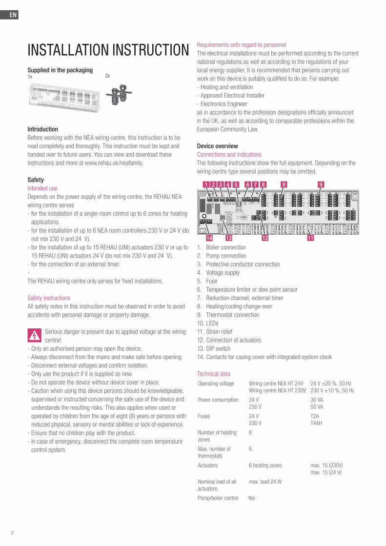
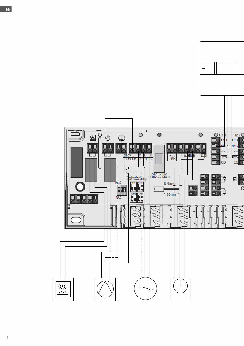
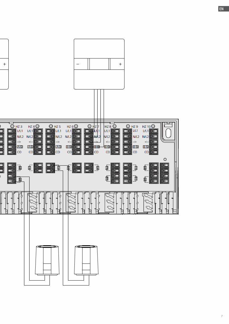
Device overviewConnections and indicationsThe following instructions show the full equipment. Depending on the wiring centre type several positions may be omitted.
HZ 1L/L1
=> => => => => =>N/L2
CO
L/L1
NC
0min 5min
N/L2
NachlaufzeitShut-down delay
24V => T2A 230V => T4A H
CO
CO
90mm
8..9mm
L/L1
N/L2
CO
L/L1
N/L2
CO
L/L1
N/L2
CO
L/L1
N/L2
CO
L/L1
N/L2
CO
L/L1
N/L2
CO
L/L1
N/L2
CO
L/L1
N/L2
CO
HZ 2 HZ 3 HZ 4 HZ 5 HZ 6 HZ 7 HZ 8 HZ 9 HZ 10
L1‘24V L2‘ L1 L2
NO
10min 15min
2 32 3
2 32 3
A A A A
=> =>
A B
=> =>
B B B BBATB%H
230V N‘ L NL‘
1 987632
12 11
4
1. Boiler connection2. Pump connection3. Protective conductor connection4. Voltage supply5. Fuse6. Temperature limiter or dew point sensor7. Reduction channel, external timer8. Heating/cooling change-over9. Thermostat connection10. LEDs11. Strain relief12. Connection of actuators13. DIP switch14. Contacts for casing cover with integrated system clock
Technical dataOperating voltage Wiring centre NEA HT 24V
Wiring centre NEA HT 230V24 V ±20 %, 50 Hz230 V ±10 %, 50 Hz
Power consumption 24 V230 V
30 VA50 VA
Fuses 24 V230 V
T2AT4AH
Number of heating zones
6
Max. number of thermostats
6
Actuators 6 heating zones max. 15 (230V)max. 15 (24 V)
Nominal load of all actuators
max. load 24 W
Pump/boiler control Yes
5 9
1314
2
EN
Switching power 2 A 200 VA inductive
Turn on delay 2 mins
Follow-up time fixed/adjustable
2 mins/ 5-15 mins
Valve protection function*
14 days for 10 minutes
Pump protection function*
14 days for 1 minute
Control direction NC or NO supplied NC values selectable
Ambient temperature 0 to +50 °C
Storage temperature -20 to +70 °C
Ambient humidity 80 % non-condensing
Protection class 24 V230 V
IIIII
Type of protection IP 20
Dimensions (H x L x D)
90 x 326.5 x 50 mm
Weight 427.6 g ±35 g
* when used with NEA H and NEA HT room controllers (value is adjustable)
ComplianceThis product is CE marked and thus is in compliance with the requirements from the guidelines: - 2004/108/EG with amendments “Council Directive on the approxi-
mation of the laws of the Member States relating to Electromagnetic Compatibility”
- 2006/95/EG with amendments “Council for Coordination of the Regulations of EU Member Countries regarding the electrical equipment for use within certain voltage limits”
- 2011/65/EU “Restriction of the Use of Certain Hazardous Substan-ces in Electrical and Electronic Equipment”
Increased protection requirements may exist for the overall installati-on, the compliance of which is the responsibility of the installer.
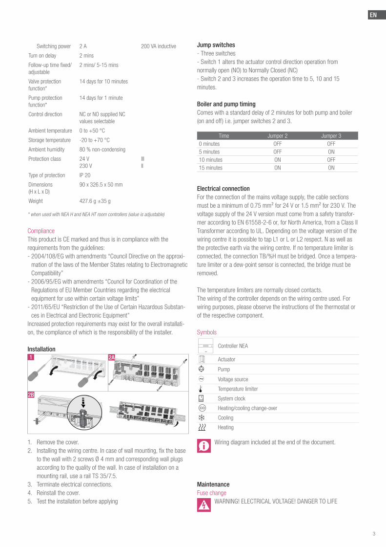
Installation
1. Remove the cover.2. Installing the wiring centre. In case of wall mounting, fix the base
to the wall with 2 screws Ø 4 mm and corresponding wall plugs according to the quality of the wall. In case of installation on a mounting rail, use a rail TS 35/7.5.
3. Terminate electrical connections.4. Reinstall the cover.5. Test the installation before applying
Jump switches- Three switches- Switch 1 alters the actuator control direction operation from normally open (NO) to Normally Closed (NC)- Switch 2 and 3 increases the operation time to 5, 10 and 15 minutes.
Boiler and pump timingComes with a standard delay of 2 minutes for both pump and boiler (on and off) i.e. jumper switches 2 and 3.
Time Jumper 2 Jumper 30 minutes OFF OFF5 minutes OFF ON10 minutes ON OFF15 minutes ON ON
Electrical connectionFor the connection of the mains voltage supply, the cable sections must be a minimum of 0.75 mm² for 24 V or 1.5 mm² for 230 V. The voltage supply of the 24 V version must come from a safety transfor-mer according to EN 61558-2-6 or, for North America, from a Class II Transformer according to UL. Depending on the voltage version of the wiring centre it is possible to tap L1 or L or L2 respect. N as well as the protective earth via the wiring centre. If no temperature limiter is connected, the connection TB/%H must be bridged. Once a tempera-ture limiter or a dew-point sensor is connected, the bridge must be removed.
The temperature limiters are normally closed contacts.The wiring of the controller depends on the wiring centre used. For wiring purposes, please observe the instructions of the thermostat or of the respective component.
Symbols
+- Controller NEA
Actuator
Pump
~ Voltage source
Temperature limiter
System clock
CO Heating/cooling change-over
Cooling
Heating
Wiring diagram included at the end of the document.
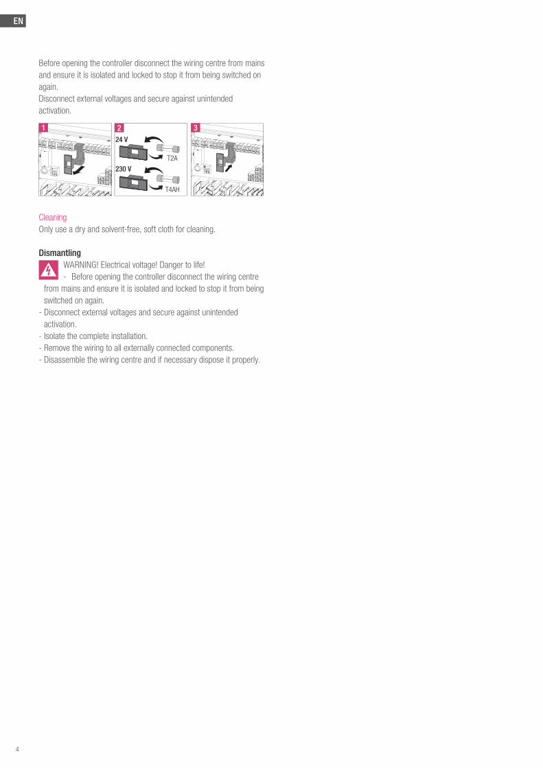
MaintenanceFuse change
WARNING! ELECTRICAL VOLTAGE! DANGER TO LIFE
1 2A
2B
3
EN
Before opening the controller disconnect the wiring centre from mains and ensure it is isolated and locked to stop it from being switched on again. Disconnect external voltages and secure against unintended activation.
2
T2A
24 V
230 V
T4AH
1 3
CleaningOnly use a dry and solvent-free, soft cloth for cleaning.
DismantlingWARNING! Electrical voltage! Danger to life!- Before opening the controller disconnect the wiring centre
from mains and ensure it is isolated and locked to stop it from being switched on again.
- Disconnect external voltages and secure against unintended activation.
- Isolate the complete installation.- Remove the wiring to all externally connected components.- Disassemble the wiring centre and if necessary dispose it properly.
4

EN
5
EN
6
EN
7

EN
© REHAU LtdSubject to technical changes.
954619 EN 04.2016
Follow REHAU Underfloor:
UK HEAD OFFICERehau Ltd, UK Head Office, Hill Court, Walford, Ross-on-Wye, Herefordshire HR9 5QN Phone: 01989 762 600 Fax: 01989 762 601
UK & IRELAND SALES OFFICE London, REHAU Ltd, The Building Centre, 25 Store Street, London WC1E 7BT Phone: 0207 580 6155 Fax: 0207 307 8595 Slough, Units 5 J & K, Langley Business Centre, Station Road, Langley, Slough SL3 8DS Phone: 01753 588500 Fax: 01753 588501 Manchester, Brinell Drive, Irlam, Manchester M44 5BL Phone: 0161 777 7400 Fax: 0161 777 7401 Glasgow, Phoenix House, Phoenix Crescent, Strathclyde Business Park, Bellshill, North Lanarkshire ML4 3NJ Phone: 01698 503700 Fax: 01698 503701 Dublin, 9 St. Johns Court, Business Park, Swords Road, Santry, Dublin 9 Phone: 00353 (0)1 8165020 Fax: 00353 (0)1 8165021
Our verbal and written application engineering advice is based upon experience and the best of our knowledge. However it is to be regarded as non-binding information. Working conditions and use under conditions for which the product was not intended and over which we have no influence exclude any claim resulting from our information. We recommend that a suitable check is made as to whether the REHAU product is suitable for the envisaged purpose. Application, use and processing of the products is carried out beyond the scope of our control and are therefore carried out exclusively at your own responsibility. If liability should still apply, then this is restricted, in the case of all damage, the value of the goods supplied by us and used by you.Our warranty applies to the consistent quality of our products as per our specification and in accordance with our general terms and conditions of delivery and payment. This document is protected by copyright. All rights based on this are reserved. No part of this publication may be translated, reproduced or transmitted in any form or by any similar means, electronic or mechanical, photocopying, recording or otherwise, or stored in a data retrieval system.
www.rehau.uk/neafamily
8

![July 27, 2009IETF NEA Meeting1 NEA Working Group IETF 75 nea[-request]@ietf.org Co-chairs: Steve Hanna shanna@juniper.netshanna@juniper.net](https://img.pdfslide.us/doc/110x75/56649ee75503460f94bf7641/july-27-2009ietf-nea-meeting1-nea-working-group-ietf-75-nea-requestietforg.jpg)