Embed Size (px)
Citation preview
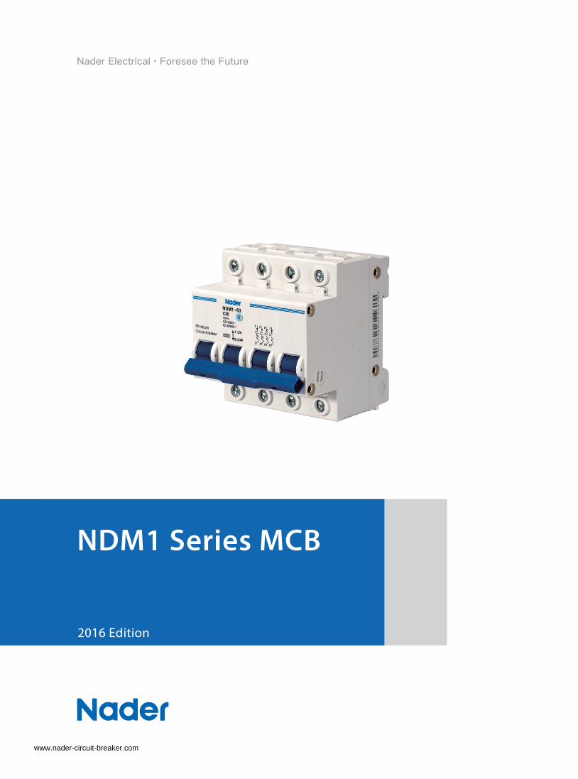
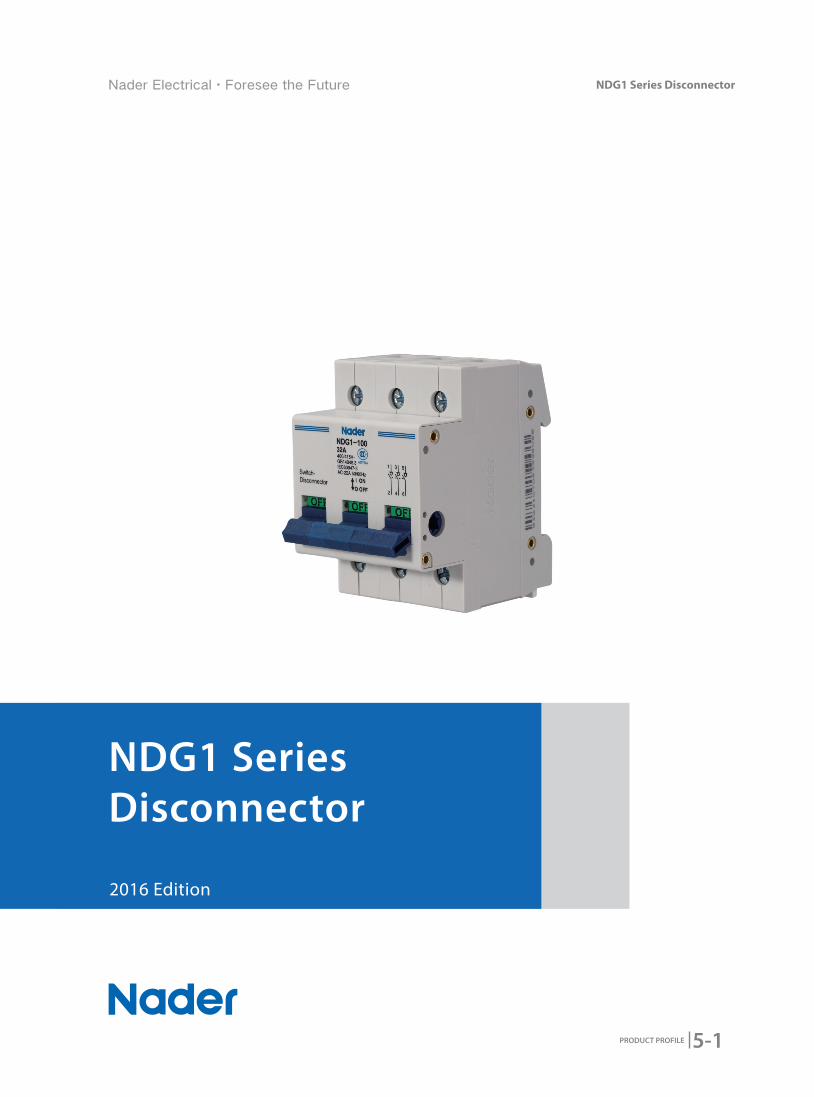
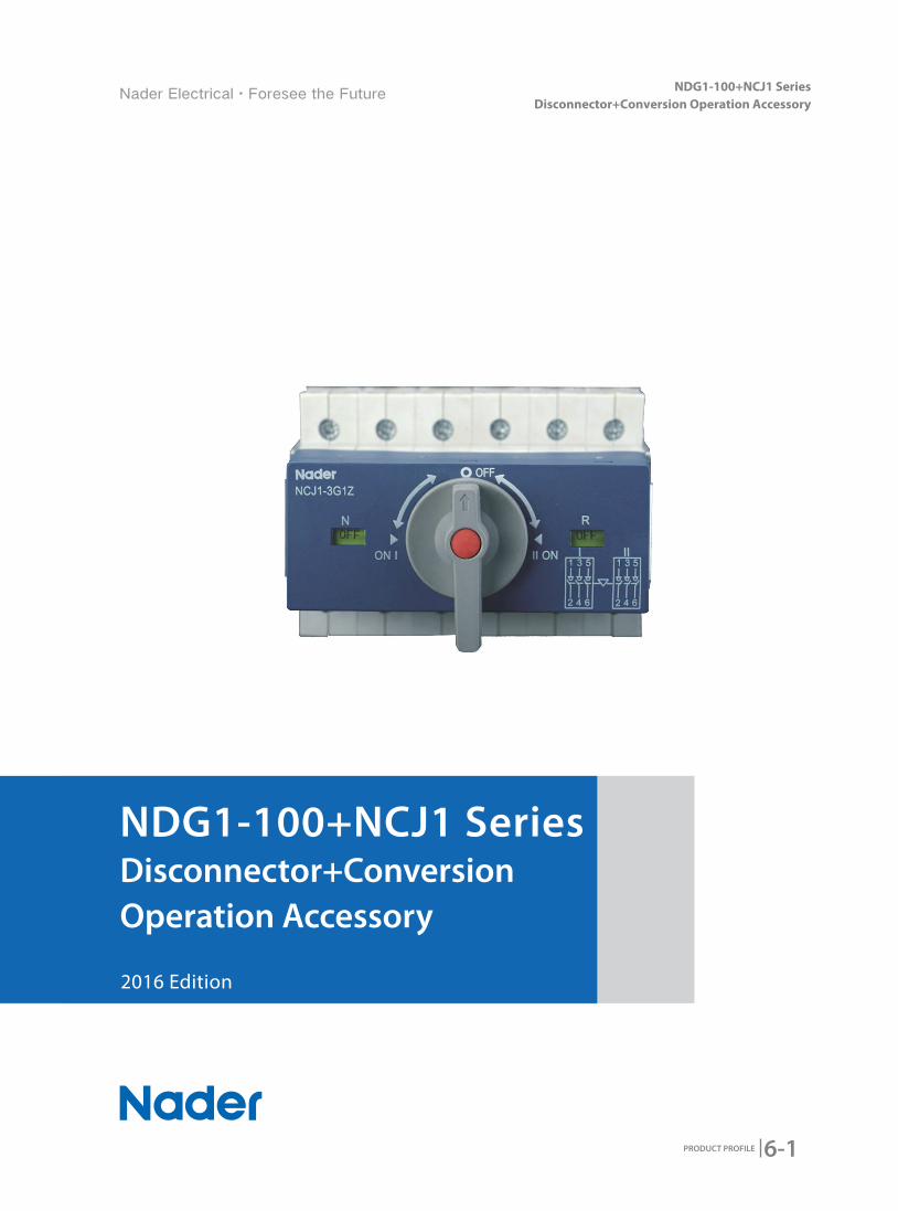
2016 Edition
NDM1 Series MCB
www.nader-circuit-breaker.com
NDM1 Series MCB
▉▉ Product▉Overview▉▉▉
▉▉ Product▉Features▉▉
▉▉ Working▉Condition▉▉
▉▉ Product▉Technical▉Characteristic▉▉
Model▉and▉Implication▉
Technical▉Parameters▉
Tripping▉Curve▉
▉▉ Accessory▉
NDM1Series▉Accessory▉Assembly▉Methods
NDM1-63,▉NDM1T-63,▉NDM1-125▉Accessory▉Types▉
▉▉ Outline▉and▉Mounting▉Dimension
NDM1-63,NDM1T-63▉RAIL▉Mounting▉Dimension▉
NDM1-125▉RAIL▉Mounting▉Dimension▉
▉▉ Wiring▉Diagram▉
▉▉ Ordering▉Types▉and▉Specifications▉
CONTENTS▉
1-1
1-2
1-2
1-4
1-5
1-5
1-6
1-8
1-11
1-11
1-11
1-12
1-12
1-14
1-16
1-16
NDM1F Series MCB
▉▉ Product▉Overview▉▉▉
▉▉ Product▉Features▉▉
▉▉ Working▉Condition▉▉
▉▉ Product▉Technical▉Characteristic▉▉
Model▉and▉Implication▉
Technical▉Parameters▉
Tripping▉Curve▉
▉▉ Accessory▉
Accessory▉Sheet▉
NDM1F-63▉Accessory▉Types▉
▉▉ Outline▉and▉Mounting▉Dimension▉
▉▉ Wiring▉Diagram▉
▉▉ Ordering▉Types▉and▉Specifications▉
CONTENTS▉▉
2-1
2-2
2-3
2-4
2-5
2-5
2-6
2-8
2-9
2-9
2-9
2-10
2-11
2-11
CONTENTS▉
NDB1 Series MCB
▉▉ Product▉Overview▉▉▉
▉▉ Product▉Features▉▉
▉▉ Working▉Condition▉▉
▉▉ Product▉Technical▉Characteristic▉▉
Model▉and▉Implication▉
Technical▉Parameters▉
Tripping▉Curve▉
▉▉ Accessory▉
Accessory▉Sheet▉
NDB1-125▉Accessory▉Types▉
▉▉ Outline▉and▉Mounting▉Dimension▉
NDB1-32▉Mounting▉Dimension▉
NDB1-125▉Mounting▉Dimension▉
▉▉ Wiring▉Diagram▉
NDB1-32▉Connecting▉
NDB1-125▉Connecting▉
▉▉ Ordering▉Types▉and▉Specifications▉
3-1
3-2
3-2
3-4
3-5
3-5
3-6
3-8
3-9
3-9
3-9
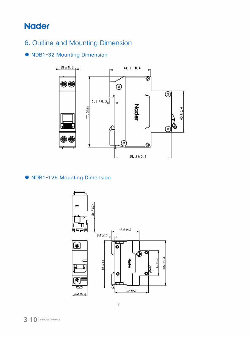
3-10
3-10
3-10
3-13
3-13
3-13
3-14

NDB1L Series RCBO
▉▉ Product▉Overview▉▉▉
▉▉ Product▉Features▉▉
▉▉ Working▉Condition▉▉
▉▉ Product▉Technical▉Characteristic▉▉
Model▉and▉Implication▉
Technical▉Parameters▉
Outline▉and▉Mounting▉Dimension▉▉
▉▉ Outline▉and▉Mounting▉Dimension▉
▉▉ Wiring▉Diagram▉
▉▉ Ordering▉Types▉and▉Specifications
4-1
4-2
4-3
4-4
4-5
4-5
4-6
4-8
4-9
4-9
4-10
CONTENTS▉▉
NDG1 Series Disconnector
▉▉ Product▉Overview▉▉▉
▉▉ Product▉Features▉▉
▉▉ Working▉Condition▉▉
▉▉ Product▉Technical▉Characteristic▉▉
Model▉and▉Implication▉
Technical▉Parameters▉
Specifications▉
▉▉ Accessory▉
Accessory▉Sheet▉
Accessory▉Function▉Introductions▉▉
Accessory▉Technical▉Parameters▉
▉▉ Outline▉and▉Mounting▉Dimension▉
NDG1-100▉Outline▉Dimension▉
NDG1-100▉Assembled▉OF3▉Outline▉Dimension▉
▉▉ Wiring▉Diagram▉
▉▉ Ordering▉Types▉and▉Specifications▉
5-1
5-2
5-3
5-4
5-5
5-5
5-5
5-6
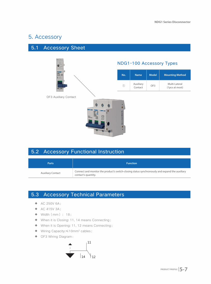
5-7
5-7
5-7
5-7
5-8
5-8
5-10
5-12
5-12
CONTENTS
CONTENTS
NDG1-100+NCJ1 Series Disconnector +
Conversion Operation Accessory
▉▉ Product▉Overview▉▉▉
▉▉ Product▉Features▉▉
▉▉ Working▉Condition▉▉
▉▉ Product▉Technical▉Characteristic▉▉
Model▉and▉Implication▉
▉▉ Outline▉and▉Mounting▉Dimension▉
▉▉ Wiring▉Diagram▉
▉▉ Ordering▉Types▉and▉Specifications▉
6-1
6-2
6-3
6-4
6-5
6-5
6-6
6-6
6-7
NDGQ1Z Series OUPA
▉▉ Product▉Overview▉▉▉
▉▉ Product▉Features▉▉
▉▉ Working▉Condition▉▉
▉▉ Product▉Technical▉Characteristic▉▉
Model▉and▉Implication▉
Technical▉Parameters▉
Status▉Indicator▉Introductions▉
▉▉ Outline▉and▉Mounting▉Dimension▉
▉▉ Wiring▉Diagram▉
▉▉ Ordering▉Types▉and▉Specifications▉
7-1
7-2
7-2
7-3
7-4
7-4
7-5
7-5
7-6
7-6
7-6
CONTENTS▉

CONTENTS▉▉
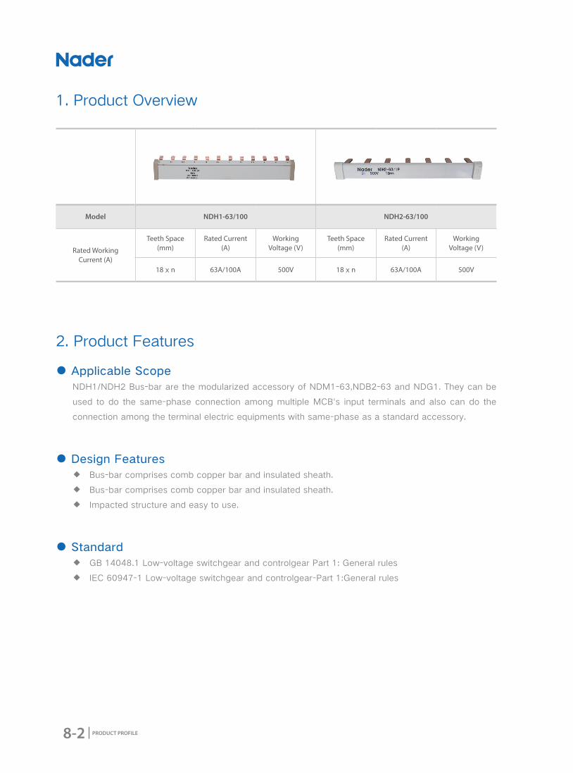
NDH Series Bus-Bar
▉▉ Product▉Overview▉▉▉
▉▉ Product▉Features▉▉
▉▉ Working▉Condition▉▉
▉▉ Product▉Technical▉Characteristic▉▉
Model▉and▉Implication▉
Technical▉Parameters▉
▉▉ Outline▉and▉Mounting▉Dimension▉
Bus-Bar▉Outline▉Dimension▉
Bus-Bar▉Length▉
▉▉ Ordering▉Types▉and▉Specifications
8-1
8-2
8-2
8-3
8-4
8-4
8-4
8-5
8-5
8-5
8-6
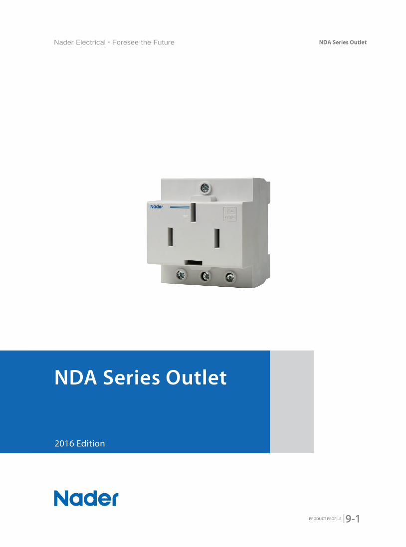
NDA Series Outlet
▉▉ Product▉Overview▉▉▉
▉▉ Product▉Features▉▉
▉▉ Working▉Condition▉▉
▉▉ Product▉Technical▉Characteristic▉▉
Model▉and▉Implication▉
Technical▉Characteristics▉
▉▉ Outline▉and▉Mounting▉Dimension▉
NDA1▉(2P▉Outline▉Dimension)
NDA1-16/34▉(3P▉Outline▉Dimension)▉
NDA1-16/46▉(4P▉Outline▉Dimension)▉
NDA1-25/48▉(4P▉Outline▉Dimension)▉▉▉
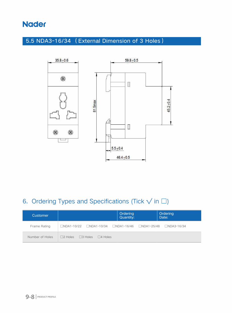
NDA3-16/34▉(3P▉Outline▉Dimension)▉
▉▉ Ordering▉Types▉and▉Specifications
9-1
9-2
9-3
9-3
9-5
9-5
9-5
9-6
9-6
9-6
9-7
9-7
9-8
9-8
CONTENTS▉▉

CONTENTS▉▉
NDM1L(NDM1) Series RCBO
▉▉ Product▉Overview▉▉▉
▉▉ Product▉Features▉▉
▉▉ Working▉Condition▉▉
▉▉ Product▉Technical▉Characteristic▉▉
Model▉and▉Implication▉
Technical▉Parameters▉
Tripping▉Curve▉
▉▉ Accessory▉
NDM1L-32、NDM1L-50、NDM1L-100▉Accessory▉Types▉
▉▉ Outline▉and▉Mounting▉Dimension▉
NDM1L-32▉RAIL▉Mounting▉Dimension▉▉
NDM1L-50▉RAIL▉Mounting▉Dimension▉
NDM1L-100▉RAIL▉Mounting▉Dimension▉
▉▉ Wiring▉Diagram▉
▉▉ Ordering▉Types▉and▉Specifications▉
10-1
10-2
10-2
10-4
10-5
10-5
10-6
10-8
10-11
10-11
10-12
10-12
10-14
10-17
10-19
10-20
NDM1GQ Series Under-voltage and
Over-voltage Protective Breaker
▉▉ Product▉Overview▉▉▉
▉▉ Product▉Features▉▉
▉▉ Working▉Condition▉▉
▉▉ Product▉Technical▉Characteristic▉▉
Model▉and▉Implication▉
Technical▉Parameters▉
Tripping▉Curve▉
▉▉ Accessory▉
Accessory▉Sheet▉
NDM1GQ-50、63▉Accessory▉Types▉
▉▉ Outline▉and▉Mounting▉Dimension▉
▉▉ Wiring▉Diagram▉
▉▉ Ordering▉Types▉and▉Specifications▉
11-1
11-2
11-3
11-4
11-5
11-5
11-6
11-8
11-10
11-10
11-10
11-11
11-12
11-13
CONTENTS▉▉
CONTENTS▉▉
OF, SD, MX+OF, NGQ1A Accessory
▉▉ Product▉Overview▉▉▉
▉▉ Application▉Scope▉▉
▉▉ Working▉Condition▉▉
▉▉ Product▉Technical▉Characteristic▉▉
OF▉Auxiliary▉Contact▉
SD▉▉Alarm▉Contact▉
MX+OF▉Shunt▉Release▉
NGQ1A▉Over▉&▉Under▉Voltage▉Release▉
▉▉ Outline▉and▉Mounting▉Dimension
OF、SD▉Outline▉Dimension▉
MX+OF▉Outline▉Dimension▉
NGQ1A▉Outline▉Dimension▉
▉▉ Connecting▉Diagram▉
▉▉ Ordering▉Types▉and▉Specifications▉
12-1
12-2
12-2
12-2
12-3
12-3
12-3
12-4
12-4
12-5
12-5
12-5
12-6
12-6
12-7
1-1
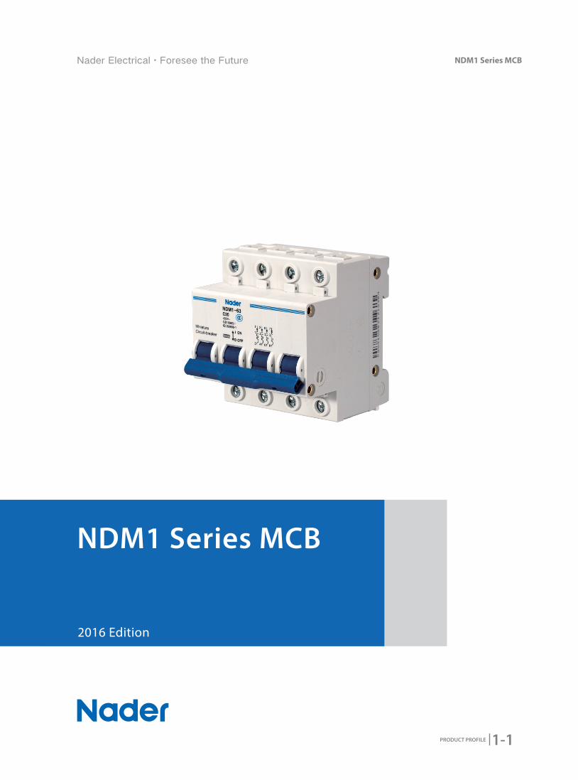
NDM1 Series MCB
PRODUCT PROFILE
2016 Edition
NDM1 Series MCB
1-2 PRODUCT PROFILE
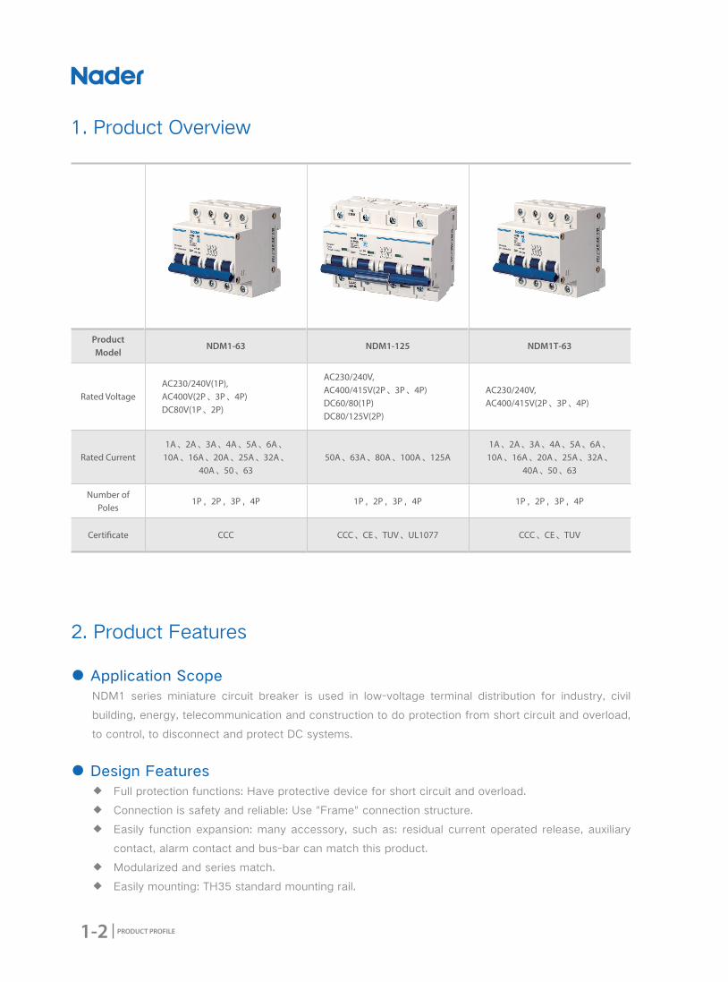
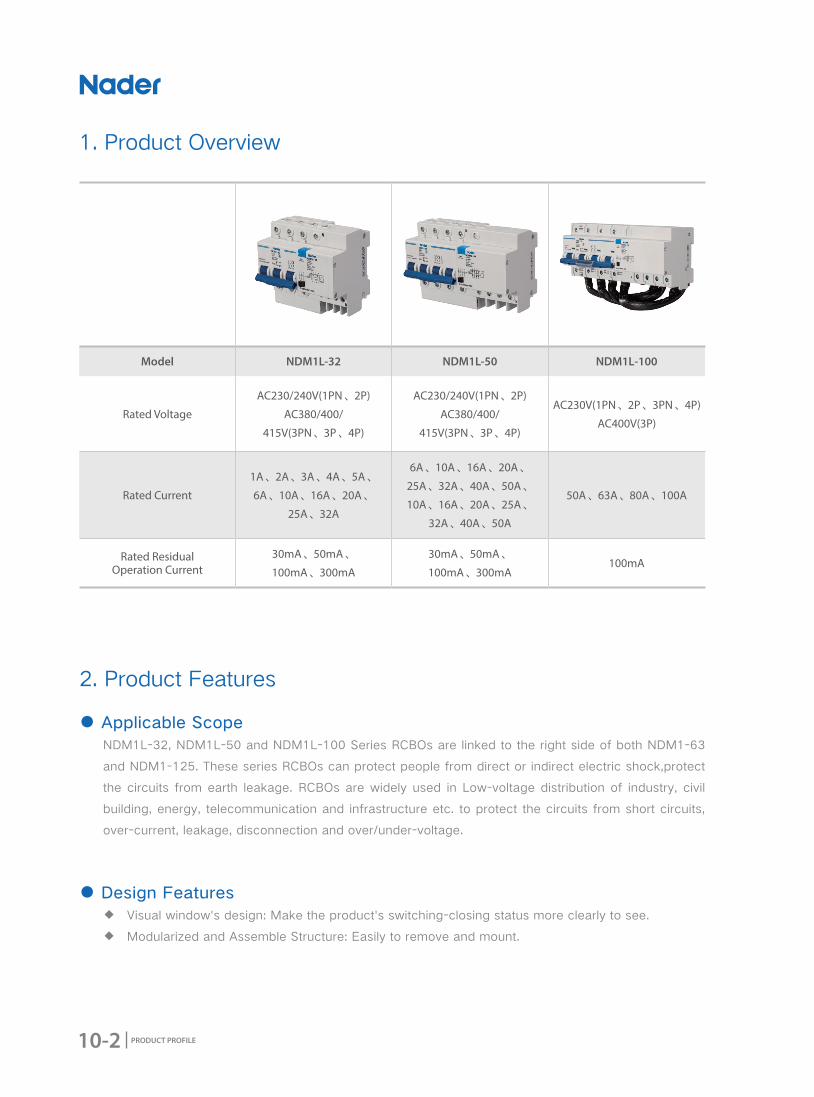
Product Model
NDM1-63 NDM1-125 NDM1T-63
Rated VoltageAC230/240V(1P),AC400V(2P、3P、4P)DC80V(1P、2P)
AC230/240V,AC400/415V(2P、3P、4P)DC60/80(1P)DC80/125V(2P)
AC230/240V, AC400/415V(2P、3P、4P)
Rated Current1A、2A、3A、4A、5A、6A、
10A、16A、20A、25A、32A、40A、50、63
50A、63A、80A、100A、125A1A、2A、3A、4A、5A、6A、
10A、16A、20A、25A、32A、40A、50、63
Number of Poles
1P,2P,3P,4P 1P,2P,3P,4P 1P,2P,3P,4P
Certi�cate CCC CCC、CE、TUV、UL1077 CCC、CE、TUV
1. Product Overview
2. Product Features
● Application ScopeNDM1 series miniature circuit breaker is used in low-voltage terminal distribution for industry, civil
building, energy, telecommunication and construction to do protection from short circuit and overload,
to control, to disconnect and protect DC systems.
● Design Features ◆ Full protection functions: Have protective device for short circuit and overload.
◆ Connection is safety and reliable: Use "Frame" connection structure.
◆ Easily function expansion: many accessory, such as: residual current operated release, auxiliary
contact, alarm contact and bus-bar can match this product.
◆ Modularized and series match.
◆ Easily mounting: TH35 standard mounting rail.
1-3
NDM1 Series MCB
PRODUCT PROFILE
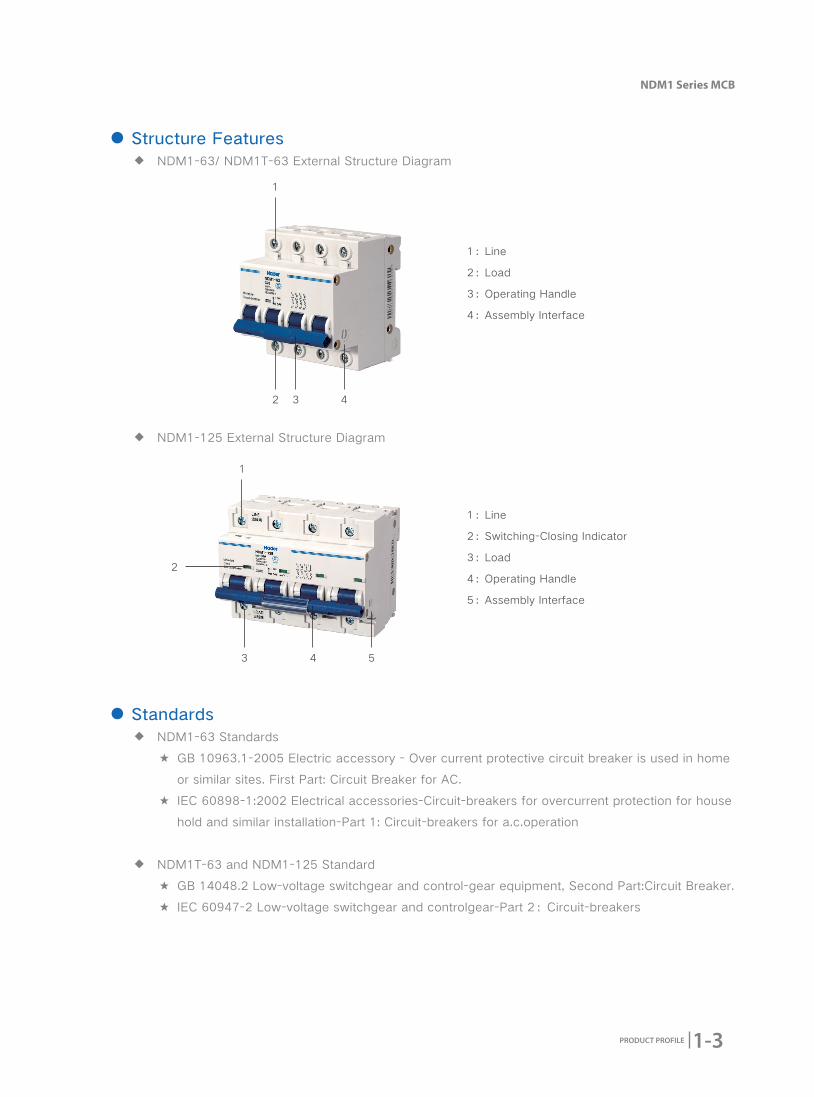
● Structure Features ◆ NDM1-63/ NDM1T-63 External Structure Diagram
◆ NDM1-125 External Structure Diagram
1
2 3 4
1
3
2
4 5
● Standards ◆ NDM1-63 Standards
★ GB 10963.1-2005 Electric accessory - Over current protective circuit breaker is used in home
or similar sites. First Part: Circuit Breaker for AC.
★ IEC 60898-1:2002 Electrical accessories-Circuit-breakers for overcurrent protection for house
hold and similar installation-Part 1: Circuit-breakers for a.c.operation
◆ NDM1T-63 and NDM1-125 Standard
★ GB 14048.2 Low-voltage switchgear and control-gear equipment, Second Part:Circuit Breaker.
★ IEC 60947-2 Low-voltage switchgear and controlgear-Part 2:Circuit-breakers
1:Line
2:Load
3:Operating Handle
4:Assembly Interface
1:Line
2:Switching-Closing Indicator
3:Load
4:Operating Handle
5:Assembly Interface
1-4 PRODUCT PROFILE
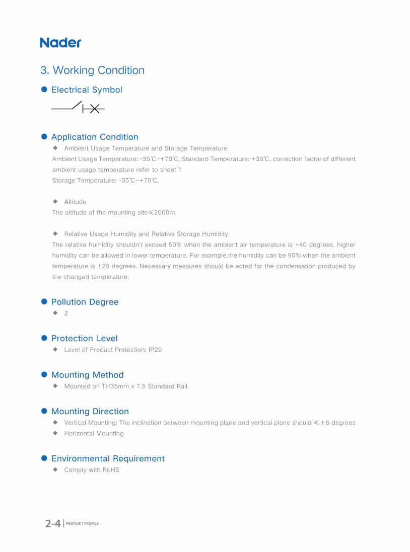
3. Working Condition
● Electrical Symbol
● Applicable Condition ◆ Ambient Usage Temperature and Storage Temperature
Ambient Usage Temperature: -35℃~+70℃, Standard Temperature: +30℃, correction factor of different
ambient usage temperature refer to sheet 1
Storage Temperature: -40℃~+70℃.
◆ Altitude
The altitude of the mounting site≤2000m.
◆ Relative Usage Humidity and Relative Storage Humidity
The relative humidity shouldn't exceed 50% when the ambient air temperature is +40 degrees, higher
humidity can be allowed in lower temperature. For example, the humidity can be 90% when the ambient
temperature is +20 degrees. Necessary measures should be acted for the condensation produced by
the changed temperature.
● Pollution Degree ◆ 3
● Protection Level ◆ Level of Product Protection: IP20
● Mounting Method ◆ Mounted on TH35mm x 7.5 Standard Rail.
● Mounting Direction ◆ Vertical Mounting:The inclination between mounting plane and vertical plane should ≤±5 degrees
◆ Horizontal Mounting
● Environmental Requirement ◆ Comply with RoHS

1-5
NDM1 Series MCB
PRODUCT PROFILE
No. Implication Instruction
1 Brand Code ND:
2 Product Code M: Miniature Circuit Breaker
3 Design Code 1
4 Product Standards GB 10963.1、IEC 60898-1
GB14048.2、IEC60947-2
GB14048.2、IEC60947-2
5 Frame Rating (A) 63A 125A 63A
6Instantaneous
Tripping Characteristics
B: Instantaneous Tripping Range 3In~5In;
C: Instantaneous Tripping Range 5In~10In;
D: Instantaneous Tripping Range 10In~14In;
C: Instantaneous Tripping Range 8In(1±20%);
D: Instantaneous Tripping Range 12In(1±20%);
B: Instantaneous Tripping Range 4In(1±20%)
C: Instantaneous Tripping Range 8In(1±20%)
D: Instantaneous Tripping Range 12In(1±20%)
7 Rated Current
1A,2A,3A,4A,5A,6A,10A,16A,20A,25A,32A,40A,50A,63A
50A,63A,80A,100A,125A
1A,2A,3A,4A,5A,6A,10A,16A,20A,25A,32A,40A,50A,63A
8 Number of Poles 1P,2P,3P,4P 1P,2P,3P,4P 1P,2P,3P,4P
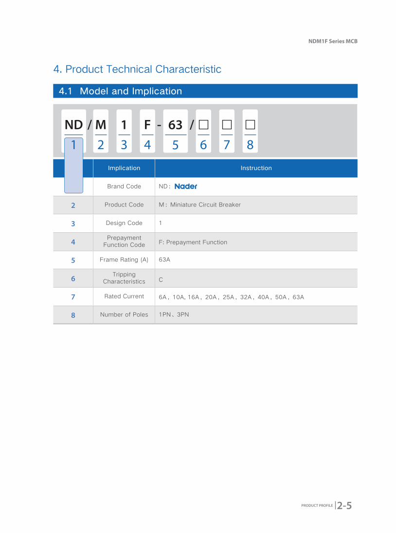
4. Product Technical Characteristic
4.1 Model and Implication
ND - // 1M
1 2 3 64 7 85
1-6 PRODUCT PROFILE
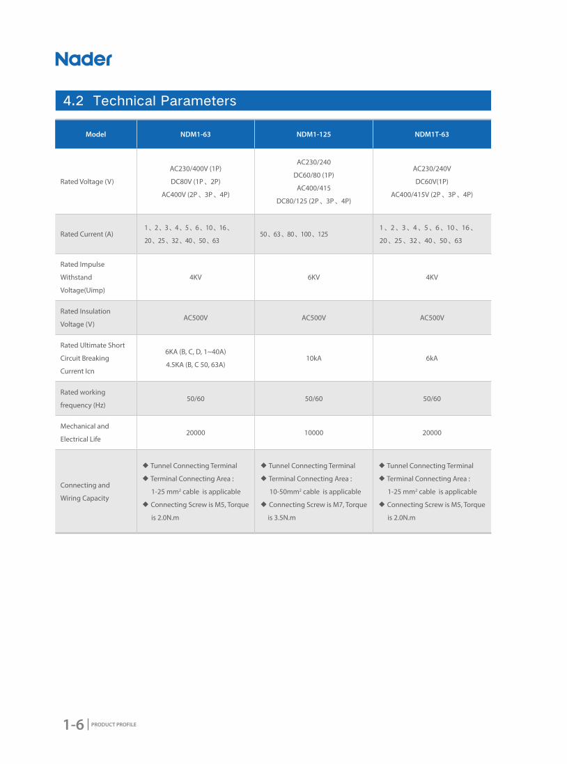
4.2 Technical Parameters
Model NDM1-63 NDM1-125 NDM1T-63
Rated Voltage (V)
AC230/400V (1P)
DC80V (1P、2P)
AC400V (2P、3P、4P)
AC230/240
DC60/80 (1P)
AC400/415
DC80/125 (2P、3P、4P)
AC230/240V
DC60V(1P)
AC400/415V (2P、3P、4P)
Rated Current (A)1、2、3、4、5、6、10、16、
20、25、32、40、50、6350、63、80、100、125
1、2、3、4、5、6、10、16、
20、25、32、40、50、63
Rated Impulse
Withstand
Voltage(Uimp)
4KV 6KV 4KV
Rated Insulation
Voltage (V)AC500V AC500V AC500V
Rated Ultimate Short
Circuit Breaking
Current Icn
6KA (B, C, D, 1~40A)
4.5KA (B, C 50, 63A)10kA 6kA
Rated working
frequency (Hz)50/60 50/60 50/60
Mechanical and
Electrical Life20000 10000 20000
Connecting and
Wiring Capacity
◆ Tunnel Connecting Terminal
◆ Terminal Connecting Area:
1-25 mm2 cable is applicable
◆ Connecting Screw is M5, Torque
is 2.0N.m
◆ Tunnel Connecting Terminal
◆ Terminal Connecting Area:
10-50mm2 cable is applicable
◆ Connecting Screw is M7, Torque
is 3.5N.m
◆ Tunnel Connecting Terminal
◆ Terminal Connecting Area:
1-25 mm2 cable is applicable
◆ Connecting Screw is M5, Torque
is 2.0N.m

1-7
NDM1 Series MCB
PRODUCT PROFILE
-35 -30 -25 -20 -15 -10 -5 -0 5 10 15
1 1.27 1.25 1.23 1.21 1.19 1.17 1.15 1.13 1.1 1.08 1.06
3 3.89 3.83 3.76 3.70 3.64 3.57 3.50 3.44 3.37 3.30 3.22
6 7.70 7.58 7.46 7.34 7.21 7.09 6.96 6.83 6.70 6.56 6.42
10 13.89 13.62 13.35 13.07 12.81 12.53 12.23 11.93 11.63 11.33 11.01
16 20.78 20.43 20.08 19.75 19.40 19.05 18.70 18.33 17.96 17.58 17.20
20 25.67 25.28 24.88 24.47 24.06 23.64 23.22 22.78 22.34 21.89 21.43
25 32.21 31.72 31.22 30.70 30.18 29.65 29.10 28.55 27.98 27.41 26.82
32 41.04 40.46 39.82 39.17 38.51 37.84 37.15 36.47 35.75 35.03 34.30
40 51.63 50.86 50.04 40.21 48.37 47.51 46.63 45.74 44.83 43.90 42.95
50 64.92 63.97 62.92 61.86 60.77 59.67 58.54 57.40 56.23 55.05 53.81
63 83.48 82.06 80.64 79.19 77.72 76.22 74.70 73.14 71.54 69.91 68.24
80 135 130 126 122 118 115 112 108 104 99 95
100 160 155 150 146 142 137 133 129 125 122 118
20 25 30 35 40 45 50 55 60 65 70
1 1.05 1.02 1.00 0.97 0.94 0.91 0.89 0.86 0.83 0.80 0.77
3 3.14 3.06 3.00 2.92 2.84 2.76 2.67 2.58 2.49 2.38 2.27
6 6.27 6.14 6.00 5.84 5.68 5.52 5.36 5.19 5.01 4.83 4.64
10 10.67 10.34 10.00 9.63 9.24 8.85 8.45 8.01 7.55 7.06 6.55
16 16.80 16.40 16.00 15.55 15.11 14.66 14.20 13.71 13.21 12.70 12.75
20 20.96 20.47 20.00 19.47 18.95 18.42 17.87 17.30 16.71 16.10 15.47
25 26.22 25.61 25.00 24.33 23.67 23.00 22.28 21.56 20.80 20.02 19.21
32 33.54 32.77 32.00 31.17 30.34 29.48 28.60 27.69 26.75 25.78 24.77
40 41.98 40.99 40.00 38.93 37.85 36.75 35.61 34.43 33.21 31.95 30.63
50 52.56 51.28 50.00 47.82 46.24 44.81 43.33 41.81 40.23 38.58 35.77
63 66.53 64.78 63.00 60.11 58.19 56.21 54.16 52.03 49.81 47.50 43.05
80 91 88 85 82 80 75.5 72.5 68 64.50 58 52.50
100 114 111 108 103 100 94 88 82 75 68 58
● Temperature Correction Factor Sheet (1) Ambient
Temperature(℃)
Ambient
Temperature(℃)
Correction Current (A)
Correction Current (A)
Rated Current(A)
Rated Current(A)
1-8 PRODUCT PROFILE
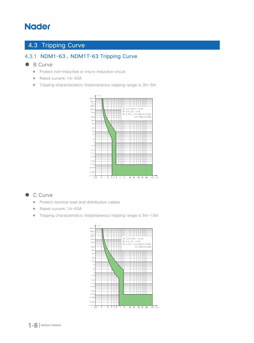
4.3.1 NDM1-63、NDM1T-63 Tripping Curve
● B Curve ★ Protect non-inductive or micro inductive circuit
★ Rated current: 1A~63A
★ Tripping characteristics: Instantaneous tripping range is 3In~5In
● C Curve ★ Protect nominal load and distribution cables
★ Rated current: 1A~63A
★ Tripping characteristics: Instantaneous tripping range is 5In~10In
4.3 Tripping Curve

1-9
NDM1 Series MCB
PRODUCT PROFILE
4.3.2 NDM1-125 Tripping Curve
● C Curve ★ Protect nominal load and distribution cables
★ Rated current: 50A~100A
★ Tripping characteristics: Instantaneous tripping range is 8In(1±20%)
● D Curve ★ Protect industrial distribution systems
★ Rated Current: 1A~63A
★ Tripping characteristics: Instantaneous tripping range is 10In~14In
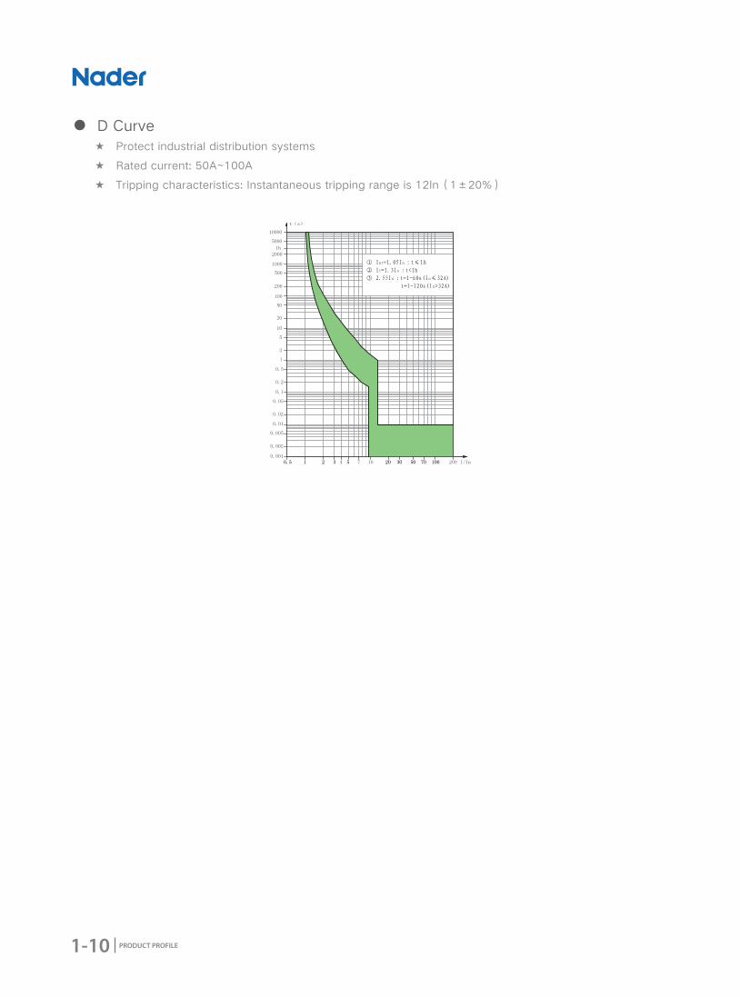
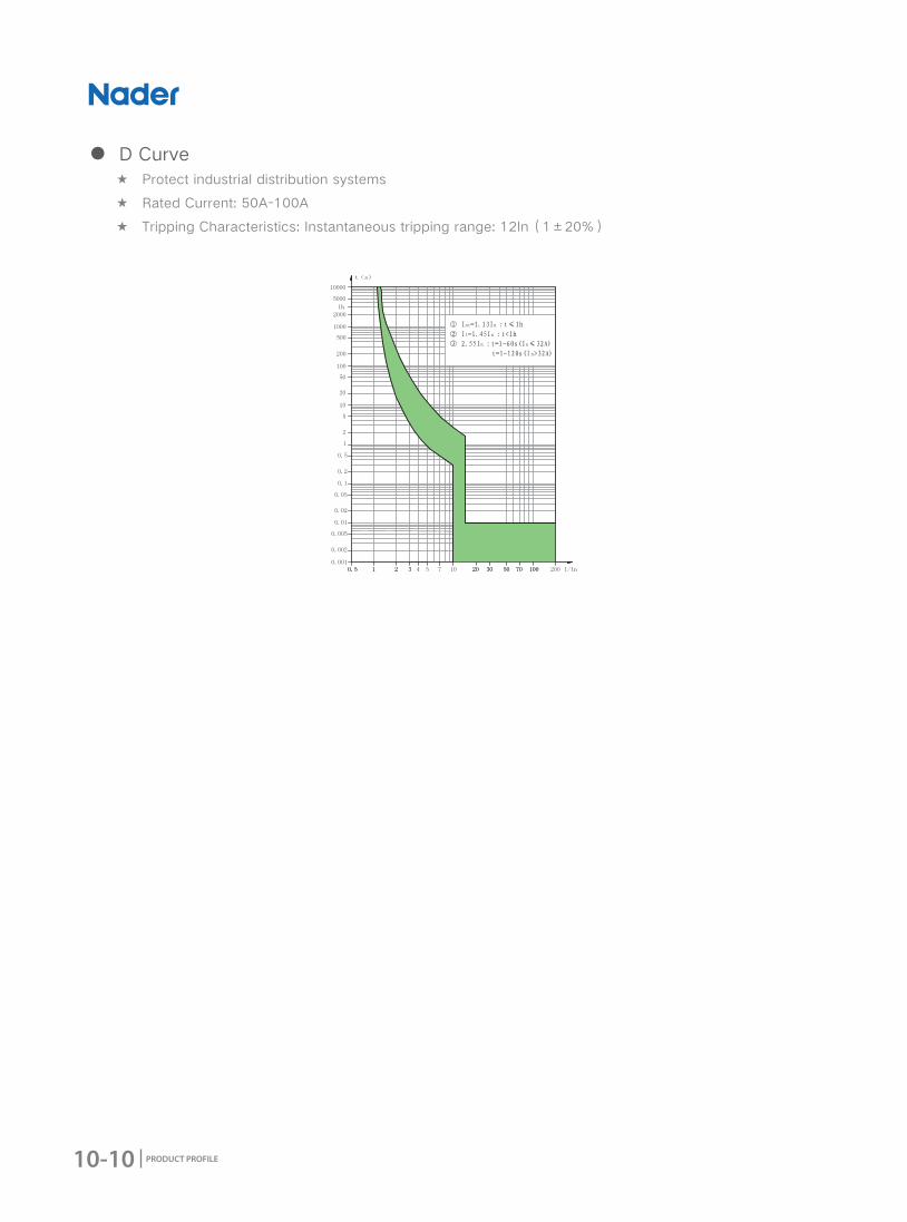
1-10 PRODUCT PROFILE
● D Curve ★ Protect industrial distribution systems
★ Rated current: 50A~100A
★ Tripping characteristics: Instantaneous tripping range is 12In(1±20%)
1-11
NDM1 Series MCB
PRODUCT PROFILE
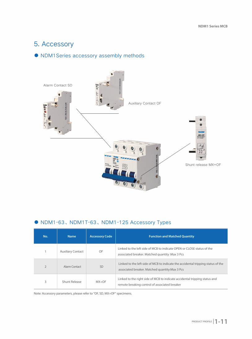
5. Accessory
● NDM1Series accessory assembly methods
Note: Accessory parameters, please refer to "OF, SD, MX+OF" specimens.
● NDM1-63、NDM1T-63、NDM1-125 Accessory Types
No. Name Accessory Code Function and Matched Quantity
1 Auxiliary Contact OFLinked to the left side of MCB to indicate OPEN or CLOSE status of the
associated breaker. Matched quantity :Max 3 Pcs
2 Alarm Contact SDLinked to the left side of MCB to indicate the accidental tripping status of the
associated breaker. Matched quantity:Max 3 Pcs
3 Shunt Release MX+OFLinked to the right side of MCB to indicate accidental tripping status and
remote breaking control of associated breaker
Auxiliary Contact OF
Shunt release MX+OF
Alarm Contact SD
1-12 PRODUCT PROFILE
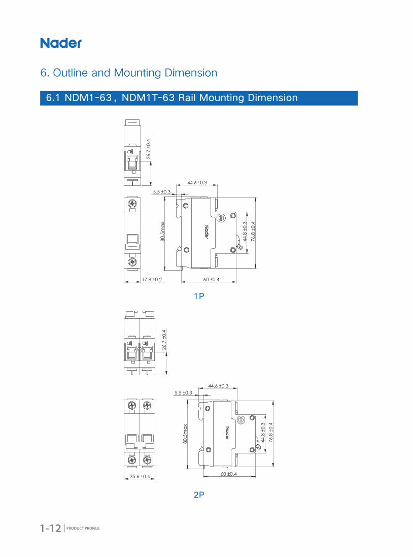
6. Outline and Mounting Dimension
6.1 NDM1-63,NDM1T-63 Rail Mounting Dimension
1P
2P

1-13
NDM1 Series MCB
PRODUCT PROFILE
3P
4P
44.8
±0.3
60 ±0.4
80.5
max
44.6 ±0.3
76.8
±0.4
5.5 ±0.3
26.7
±0.4
53.4 ±0.6
44.8
±0.3
60 ±0.4
80.5
max
5.5 ±0.3
44.6 ±0.3
76.8
±0.4
26.7
±0.4
71.2 ±0.8
1-14 PRODUCT PROFILE
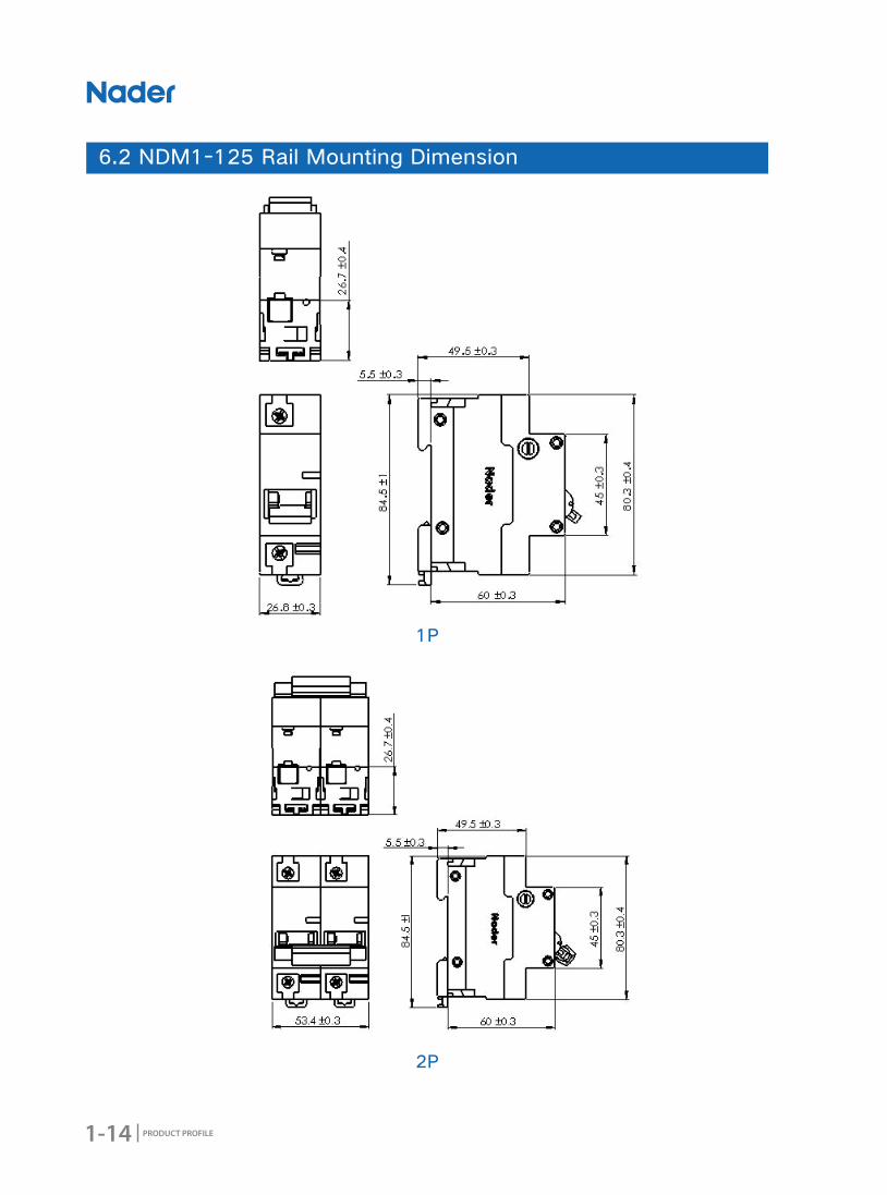
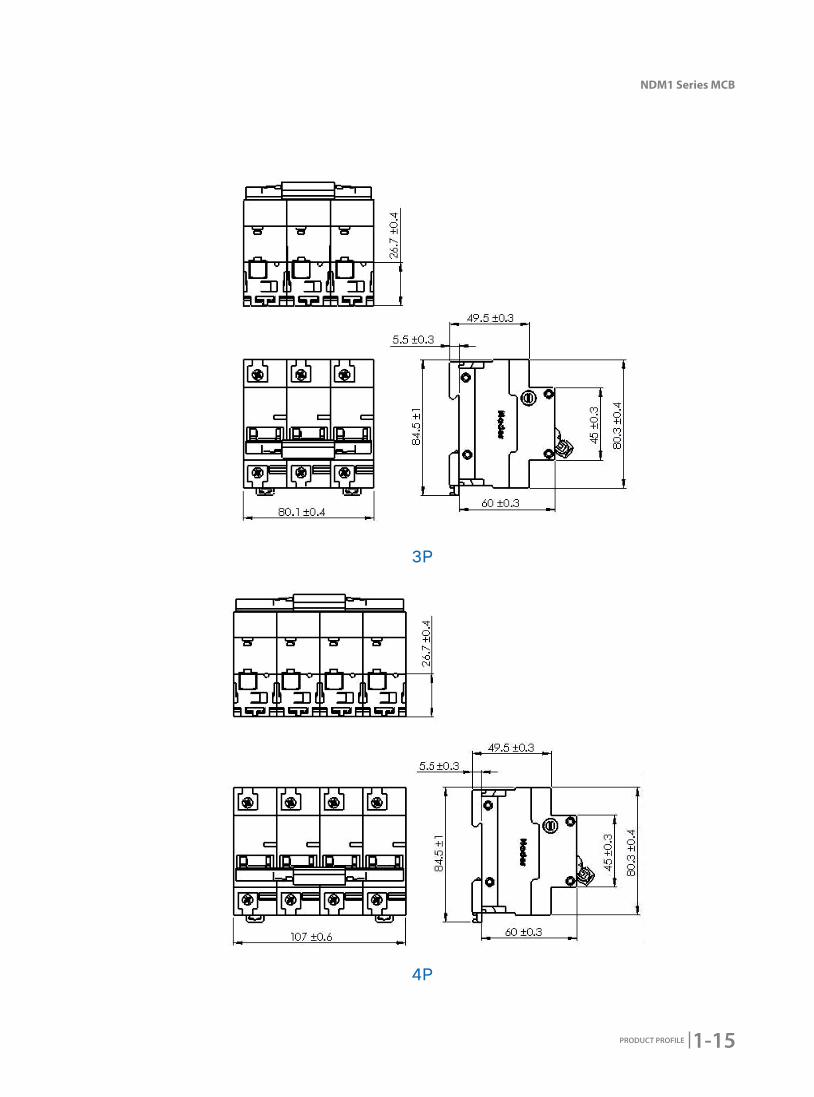
6.2 NDM1-125 Rail Mounting Dimension
1P
2P
1-15
NDM1 Series MCB
PRODUCT PROFILE
3P
4P

1-16 PRODUCT PROFILE
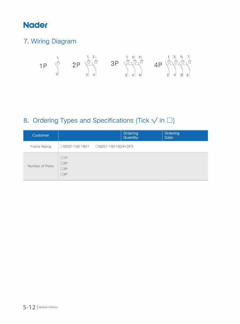
7. Wiring Diagram
NDM1-63,NDM1T-63,NDM1-125
8. Ordering Types and Specifications (Tick √ in □)
CustomerOrdering Quantity:
Ordering Date:
Model □NDM1-63 □NDM1T-63 □NDM1-125
Number of Poles
□1P □2P □3P □4P □1P □2P □3P □4P
Rate Working Current (A)
1、2、3、4、5、6、10、16、20、25、32、40、50、63
50、63、80、100、125
Tripping Characteristics
□B:Instantaneous tripping range 3In~5In, protect non-inductive and micro inductive circuits
□C:Instantaneous tripping range 5In~10In, protect nominal load and distribution cables
□D:Instantaneous tripping range 10In~14In, protect industrial distribution systems
□C:Instantaneous tripping range 5In~10In,protect nominal load and distribution cables
□D:Instantaneous tripping range 10In~14In,protect industrial distribution systems
Load Load Load

2-1
NDM1F Series MCB
PRODUCT PROFILE
2016 Edition
NDM1F Series MCB

2-2 PRODUCT PROFILE
Product Model NDM1F-63
Rated Voltage AC230/240V AC400/415V
Rated Current 6A,10A,16A,20A,25A,32A,40A,50A,63A
Number of Poles 1PN 3PN
Certi�cate CCC CCC
1. Product Overview

2-3
NDM1F Series MCB
PRODUCT PROFILE
2. Product Features
● Application ScopeNDM1F-63 Series prepayment circuit breaker (hereafter referred to as circuit breaker), applied to AC
50\60Hz, rated working voltage 415V, rated current 63A circuits. circuit breaker can control breaking
in remote distance or control breaking by automatic signal and protect the circuits from overload and
short circuit. Circuit breaker also can be used to non-frequently convert circuits.
At present, circuit breaker is widely applied to control circuit's breaking together with the electric meters
which do prepayment by IC card.
● Design Features ◆ Visual window's design:Make the product's switching-closing status more clearly to see.
◆ Modularized: Easily to remove and mount.
● Structure Features ◆ NDM1F-63 External Structure Diagram
1:Line
2:Load
3:Operating Handle
4:Signal connecting cable
1
2
3
4
● Standards ◆ GB10963.1 Electrical accessories-Circuit-breakers for over-current protection for household and
similar installation-Part 1: Circuit-breakers for AC operation
◆ IEC60898-1 Electrical accessories-Circuit-breakers for overcurrent protection for household and
similar installation-Part 1: Circuit-breakers for a.c. operation
2-4 PRODUCT PROFILE
3. Working Condition
● Electrical Symbol
● Application Condition ◆ Ambient Usage Temperature and Storage Temperature
Ambient Usage Temperature: -35℃~+70℃, Standard Temperature: +30℃, correction factor of different
ambient usage temperature refer to sheet 1
Storage Temperature: -35℃~+70℃.
◆ Altitude
The altitude of the mounting site≤2000m.
◆ Relative Usage Humidity and Relative Storage Humidity
The relative humidity shouldn't exceed 50% when the ambient air temperature is +40 degrees, higher
humidity can be allowed in lower temperature. For example,the humidity can be 90% when the ambient
temperature is +20 degrees. Necessary measures should be acted for the condensation produced by
the changed temperature.
● Pollution Degree ◆ 2
● Protection Level ◆ Level of Product Protection: IP20
● Mounting Method ◆ Mounted on TH35mm x 7.5 Standard Rail.
● Mounting Direction ◆ Vertical Mounting: The inclination between mounting plane and vertical plane should ≤±5 degrees
◆ Horizontal Mounting
● Environmental Requirement ◆ Comply with RoHS
2-5
NDM1F Series MCB
PRODUCT PROFILE
No. Implication Instruction
1 Brand Code ND:
2 Product Code M:Miniature Circuit Breaker
3 Design Code 1
4Prepayment
Function Code F: Prepayment Function
5 Frame Rating (A) 63A
6Tripping
Characteristics C
7 Rated Current 6A,10A, 16A,20A,25A,32A,40A,50A,63A
8 Number of Poles 1PN、3PN
4. Product Technical Characteristic
4.1 Model and Implication
ND - // 1 F 63M
1 2 3 64 7 85
2-6 PRODUCT PROFILE
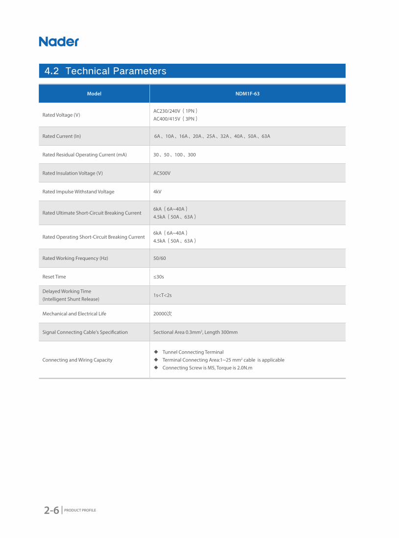
4.2 Technical Parameters
Model NDM1F-63
Rated Voltage (V)AC230/240V(1PN) AC400/415V(3PN)
Rated Current (In) 6A、10A、16A、20A、25A、32A、40A、50A、63A
Rated Residual Operating Current (mA) 30、50、100、300
Rated Insulation Voltage (V) AC500V
Rated Impulse Withstand Voltage 4kV
Rated Ultimate Short-Circuit Breaking Current6kA(6A~40A)
4.5kA(50A、63A)
Rated Operating Short-Circuit Breaking Current 6kA(6A~40A)
4.5kA(50A、63A)
Rated Working Frequency (Hz) 50/60
Reset Time ≤30s
Delayed Working Time (Intelligent Shunt Release)
1s<T<2s
Mechanical and Electrical Life 20000次
Signal Connecting Cable's Speci�cation Sectional Area 0.3mm2, Length 300mm
Connecting and Wiring Capacity ◆ Tunnel Connecting Terminal ◆ Terminal Connecting Area:1~25 mm2 cable is applicable ◆ Connecting Screw is M5, Torque is 2.0N.m

2-7
NDM1F Series MCB
PRODUCT PROFILE
-35 -30 -25 -20 -15 -10 -5 -0 5 10 15
6 7.70 7.58 7.46 7.34 7.21 7.09 6.96 6.83 6.70 6.56 6.42
10 13.89 13.62 13.35 13.07 12.81 12.53 12.23 11.93 11.63 11.33 11.01
16 20.78 20.43 20.08 19.75 19.40 19.05 18.70 18.33 17.96 17.58 17.20
20 25.67 25.28 24.88 24.47 24.06 23.64 23.22 22.78 22.34 21.89 21.43
25 32.21 31.72 31.22 30.70 30.18 29.65 29.10 28.55 27.98 27.41 26.82
32 41.04 40.46 39.82 39.17 38.51 37.84 37.15 36.47 35.75 35.03 34.30
40 51.63 50.86 50.04 40.21 48.37 47.51 46.63 45.74 44.83 43.90 42.95
50 64.92 63.97 62.92 61.86 60.77 59.67 58.54 57.40 56.23 55.05 53.81
63 83.48 82.06 80.64 79.19 77.72 76.22 74.70 73.14 71.54 69.91 68.24
20 25 30 35 40 45 50 55 60 65 70
6 6.27 6.14 6.00 5.84 5.68 5.52 5.36 5.19 5.01 4.83 4.64
10 10.67 10.34 10.00 9.63 9.24 8.85 8.45 8.01 7.55 7.06 6.55
16 16.80 16.40 16.00 15.55 15.11 14.66 14.20 13.71 13.21 12.70 12.75
20 20.96 20.47 20.00 19.47 18.95 18.42 17.87 17.30 16.71 16.10 15.47
25 26.22 25.61 25.00 24.33 23.67 23.00 22.28 21.56 20.80 20.02 19.21
32 33.54 32.77 32.00 31.17 30.34 29.48 28.60 27.69 26.75 25.78 24.77
40 41.98 40.99 40.00 38.93 37.85 36.75 35.61 34.43 33.21 31.95 30.63
50 52.56 51.28 50.00 47.82 46.24 44.81 43.33 41.81 40.23 38.58 35.77
63 66.53 64.78 63.00 60.11 58.19 56.21 54.16 52.03 49.81 47.50 43.05
● Temperature Correction Factor Sheet (1)
Ambient
Temperature(℃)
Correction Current (A)
Rated Current(A)
Ambient
Temperature(℃)
Correction Current (A)
Rated Current(A)

2-8 PRODUCT PROFILE
● C Curve ★ Protect Lighting Distribution Circuits
★ Rated Current: 6A~63A
★ Tripping Characteristics: Instantaneous Tripping Range 5In~10In
4.3 Tripping Curve

2-9
NDM1F Series MCB
PRODUCT PROFILE
5.1 Accessory Sheet
5.2 NDM1F-63 Accessory Types
5. Accessory
Note: Accessory parameters, please refer to "OF、SD" specimens.
No. Name Accessory Code Function and Matched Quantity
1 Auxiliary Contact OFLinked to the left side of MCB to indicate OPEN or CLOSE status of the associated
breaker. Matched quantity: 3 Pcs Max.
2 Alarm Contact SDLinked to the left side of MCB to indicate the accidental tripping status of the
associated breaker. Matched quantity: 3 Pcs Max.
Auxiliary Contact OF
Alarm Contact SD
2-10 PRODUCT PROFILE
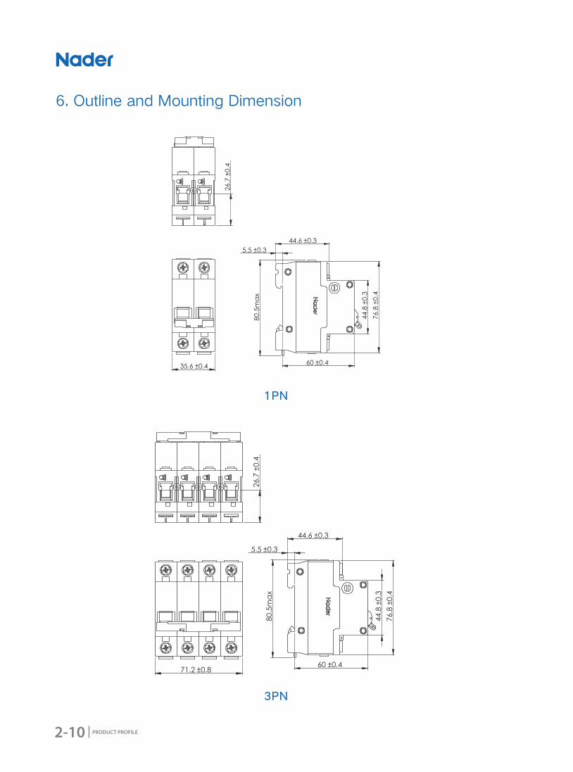
6. Outline and Mounting Dimension
1PN
3PN
44.8
±0.3
60 ±0.4
80.5
max
5.5 ±0.3
44.6 ±0.3
76.8
±0.4
26.7
±0.4
71.2 ±0.8

2-11
NDM1F Series MCB
PRODUCT PROFILE
1PN Electrical Connecting Diagram
3PN Electrical Connecting Diagram
7. Wiring Diagram
8. Ordering Types and Specifications(Tick √ in □)
CustomerOrdering Quantity:
Ordering Date:
Model □NDM1F-63
Rated Working Voltage (V)
□AC230/240 □AC400/415
Rated Working Current (A)
6、10、16、20、25、32、40、50、63
Number of Poles □1PN □3PN

2-12 PRODUCT PROFILE

3-1
NDB1 Series MCB
PRODUCT PROFILE
2016 Edition
NDB1 Series MCB
3-2 PRODUCT PROFILE
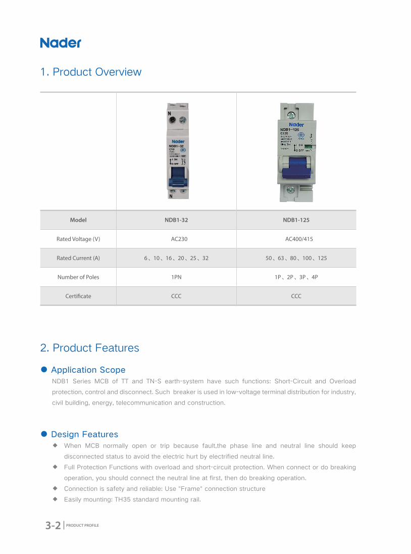
Model NDB1-32 NDB1-125
Rated Voltage (V) AC230 AC400/415
Rated Current (A) 6、10、16、20、25、32 50、63、80、100、125
Number of Poles 1PN 1P、2P、3P、4P
Certi�cate CCC CCC
1. Product Overview
2. Product Features
● Application ScopeNDB1 Series MCB of TT and TN-S earth-system have such functions: Short-Circuit and Overload
protection, control and disconnect. Such breaker is used in low-voltage terminal distribution for industry,
civil building, energy, telecommunication and construction.
● Design Features ◆ When MCB normally open or trip because fault,the phase line and neutral line should keep
disconnected status to avoid the electric hurt by electrified neutral line.
◆ Full Protection Functions with overload and short-circuit protection. When connect or do breaking
operation, you should connect the neutral line at first, then do breaking operation.
◆ Connection is safety and reliable: Use "Frame" connection structure
◆ Easily mounting: TH35 standard mounting rail.
3-3
NDB1 Series MCB
PRODUCT PROFILE
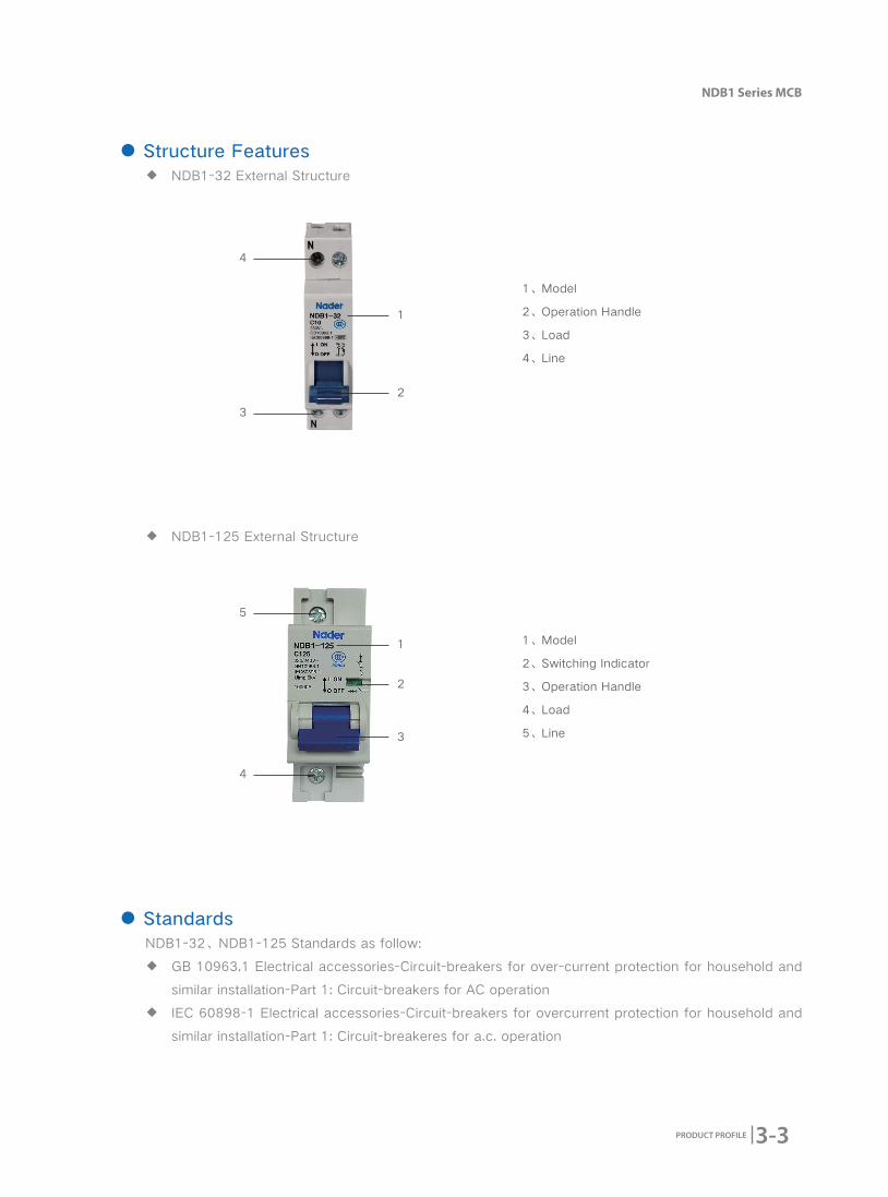
● Structure Features ◆ NDB1-32 External Structure
◆ NDB1-125 External Structure
1、Model
2、Operation Handle
3、Load
4、Line
● StandardsNDB1-32、NDB1-125 Standards as follow:
◆ GB 10963.1 Electrical accessories-Circuit-breakers for over-current protection for household and
similar installation-Part 1: Circuit-breakers for AC operation
◆ IEC 60898-1 Electrical accessories-Circuit-breakers for overcurrent protection for household and
similar installation-Part 1: Circuit-breakeres for a.c. operation
1
2
4
3
1、Model
2、Switching Indicator
3、Operation Handle
4、Load
5、Line3
2
1
5
4

3-4 PRODUCT PROFILE
3. Working Condition
● Electrical symbol
● Applicable Condition ◆ Ambient Usage Temperature and Storage Temperature
Ambient Usage Temperature: -35℃~+70℃, Standard Temperature: +30℃, correction factor of different
ambient usage temperature refer to sheet 1
Storage Temperature: -35℃~+70℃.
◆ Altitude
The altitude of the mounting site≤2000m
◆ Relative Usage Humidity and Relative Storage Humidity
The relative humidity shouldn't exceed 50% when the ambient air temperature is +40 degrees, higher
humidity can be allowed in lower temperature. For example, the humidity can be 90% when the ambient
temperature is +20 degrees. Necessary measures should be acted for the condensation produced by
the changed temperature.
● Pollution Degree2
● Protection LevelLevel of Product Protection: IP20
● Mounting TypesⅡ(For Load Level) and Ⅲ(For distribution and control Level)
● Mounting MethodMounted on TH35mm x 7.5 Standard Rail.
● Mounting Direction ◆ Vertical Mounting: The inclination between mounting plane and vertical plane should ≤±5 degrees
◆ Horizontal Mounting
● Environmental RequirementComply with RoHS
3-5
NDB1 Series MCB
PRODUCT PROFILE
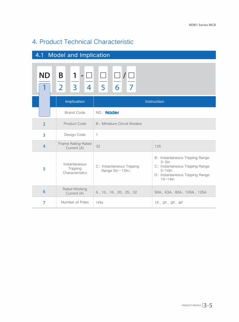
No. Implication Instruction
1 Brand Code ND:
2 Product Code B:Miniature Circuit Breaker
3 Design Code 1
4Frame Rating-Rated
Current (A) 32 125
5Instantaneous
Tripping Characteristics
C:Instantaneous Tripping Range 5In~10In;
B:Instantaneous Tripping Range 3~5In
C:Instantaneous Tripping Range 5~10In
D:Instantaneous Tripping Range 10~14In
6Rated Working
Current (A) 6,10,16,20,25,32 50A,63A,80A,100A,125A
7 Number of Poles 1PN 1P,2P,3P,4P
4. Product Technical Characteristic
4.1 Model and Implication
ND - /1B
1 2 3 54 6 7
3-6 PRODUCT PROFILE
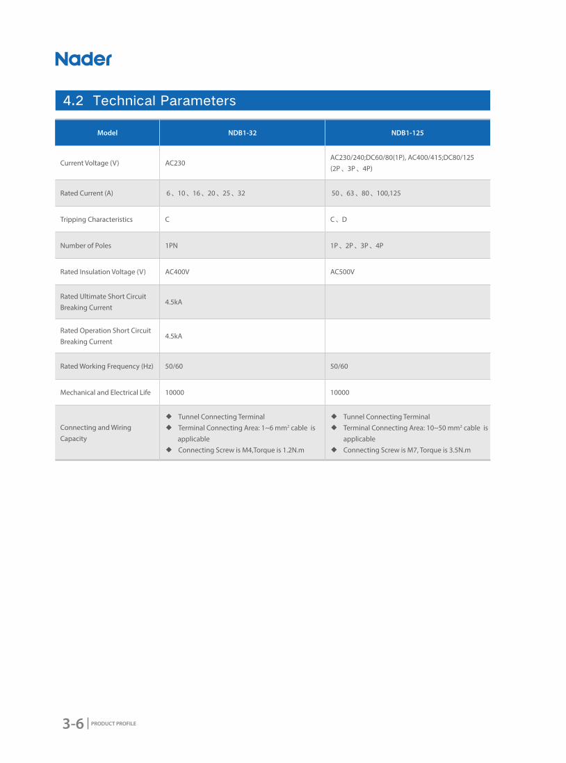
4.2 Technical Parameters
Model NDB1-32 NDB1-125
Current Voltage (V) AC230AC230/240;DC60/80(1P), AC400/415;DC80/125 (2P、3P、4P)
Rated Current (A) 6、10、16、20、25、32 50、63、80、100,125
Tripping Characteristics C C、D
Number of Poles 1PN 1P、2P、3P、4P
Rated Insulation Voltage (V) AC400V AC500V
Rated Ultimate Short Circuit Breaking Current
4.5kA
Rated Operation Short Circuit Breaking Current
4.5kA
Rated Working Frequency (Hz) 50/60 50/60
Mechanical and Electrical Life 10000 10000
Connecting and Wiring Capacity
◆ Tunnel Connecting Terminal ◆ Terminal Connecting Area: 1~6 mm2 cable is
applicable ◆ Connecting Screw is M4,Torque is 1.2N.m
◆ Tunnel Connecting Terminal ◆ Terminal Connecting Area: 10~50 mm2 cable is
applicable ◆ Connecting Screw is M7, Torque is 3.5N.m
3-7
NDB1 Series MCB
PRODUCT PROFILE
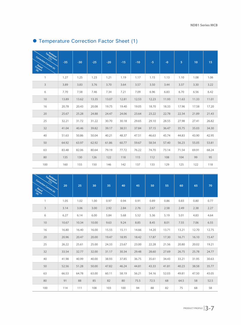
-35 -30 -25 -20 -15 -10 -5 -0 5 10 15
1 1.27 1.25 1.23 1.21 1.19 1.17 1.15 1.13 1.10 1.08 1.06
3 3.89 3.83 3.76 3.70 3.64 3.57 3.50 3.44 3.37 3.30 3.22
6 7.70 7.58 7.46 7.34 7.21 7.09 6.96 6.83 6.70 6.56 6.42
10 13.89 13.62 13.35 13.07 12.81 12.53 12.23 11.93 11.63 11.33 11.01
16 20.78 20.43 20.08 19.75 19.40 19.05 18.70 18.33 17.96 17.58 17.20
20 25.67 25.28 24.88 24.47 24.06 23.64 23.22 22.78 22.34 21.89 21.43
25 32.21 31.72 31.22 30.70 30.18 29.65 29.10 28.55 27.98 27.41 26.82
32 41.04 40.46 39.82 39.17 38.51 37.84 37.15 36.47 35.75 35.03 34.30
40 51.63 50.86 50.04 40.21 48.37 47.51 46.63 45.74 44.83 43.90 42.95
50 64.92 63.97 62.92 61.86 60.77 59.67 58.54 57.40 56.23 55.05 53.81
63 83.48 82.06 80.64 79.19 77.72 76.22 74.70 73.14 71.54 69.91 68.24
80 135 130 126 122 118 115 112 108 104 99 95
100 160 155 150 146 142 137 133 129 125 122 118
20 25 30 35 40 45 50 55 60 65 70
1 1.05 1.02 1.00 0.97 0.94 0.91 0.89 0.86 0.83 0.80 0.77
3 3.14 3.06 3.00 2.92 2.84 2.76 2.67 2.58 2.49 2.38 2.27
6 6.27 6.14 6.00 5.84 5.68 5.52 5.36 5.19 5.01 4.83 4.64
10 10.67 10.34 10.00 9.63 9.24 8.85 8.45 8.01 7.55 7.06 6.55
16 16.80 16.40 16.00 15.55 15.11 14.66 14.20 13.71 13.21 12.70 12.75
20 20.96 20.47 20.00 19.47 18.95 18.42 17.87 17.30 16.71 16.10 15.47
25 26.22 25.61 25.00 24.33 23.67 23.00 22.28 21.56 20.80 20.02 19.21
32 33.54 32.77 32.00 31.17 30.34 29.48 28.60 27.69 26.75 25.78 24.77
40 41.98 40.99 40.00 38.93 37.85 36.75 35.61 34.43 33.21 31.95 30.63
50 52.56 51.28 50.00 47.82 46.24 44.81 43.33 41.81 40.23 38.58 35.77
63 66.53 64.78 63.00 60.11 58.19 56.21 54.16 52.03 49.81 47.50 43.05
80 91 88 85 82 80 75.5 72.5 68 64.5 58 52.5
100 114 111 108 103 100 94 88 82 75 68 58
● Temperature Correction Factor Sheet (1)
Ambient
Temperature(℃)
Correction Current (A)
Rated Current(A)
Ambient
Temperature(℃)
Correction Current (A)
Rated Current(A)

3-8 PRODUCT PROFILE
● NDB1-32 Tripping Curve
C Curve ★ Protect nominal load and distribution cables
★ Rated Current: 6-32A
★ Tripping Characteristics: Instantaneous tripping range 5In~10In
● NDB1-125 Tripping Curve
C Curve ★ Protect lighting distribution circuits
★ Tripping Characteristics: Instantaneous
tripping range 5In~10In
D Curve ★ Protect industrial distribution systems
★ Tripping Characteristics: Instantaneous
tripping range 10In~14In
4.3 Tripping Curve
3-9
NDB1 Series MCB
PRODUCT PROFILE
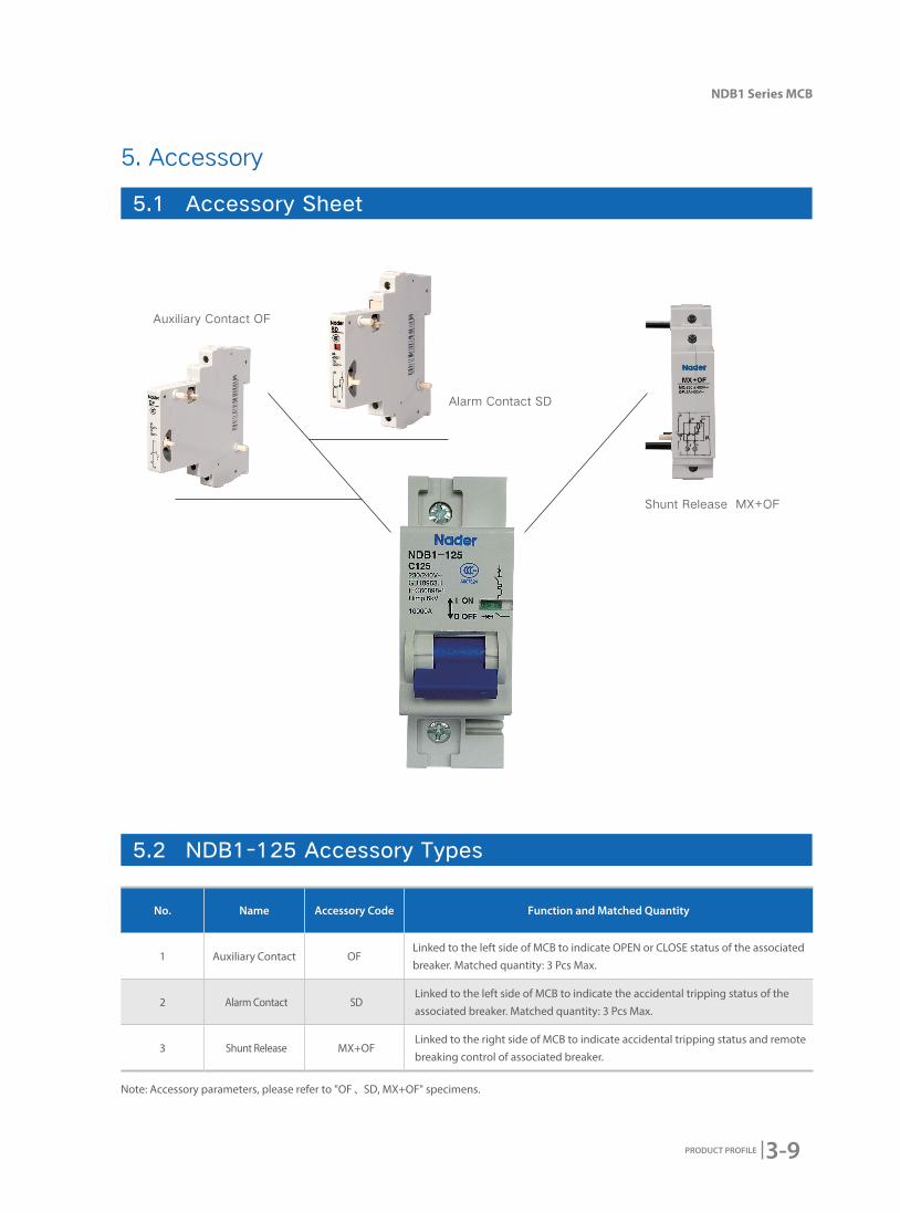
5.1 Accessory Sheet
5.2 NDB1-125 Accessory Types
5. Accessory
Note: Accessory parameters, please refer to "OF、SD, MX+OF" specimens.
No. Name Accessory Code Function and Matched Quantity
1 Auxiliary Contact OFLinked to the left side of MCB to indicate OPEN or CLOSE status of the associated breaker. Matched quantity: 3 Pcs Max.
2 Alarm Contact SDLinked to the left side of MCB to indicate the accidental tripping status of the associated breaker. Matched quantity: 3 Pcs Max.
3 Shunt Release MX+OFLinked to the right side of MCB to indicate accidental tripping status and remote breaking control of associated breaker.
Auxiliary Contact OF
Alarm Contact SD
Shunt Release MX+OF
3-10 PRODUCT PROFILE
6. Outline and Mounting Dimension
● NDB1-32 Mounting Dimension
1P
● NDB1-125 Mounting Dimension

3-11
NDB1 Series MCB
PRODUCT PROFILE
3P
2P

3-12 PRODUCT PROFILE
2P

3-13
NDB1 Series MCB
PRODUCT PROFILE
7. Wiring Diagram
● NDB1-32 Connecting
● NDB1-125 Connecting
LoadLoadLoad
3-14 PRODUCT PROFILE
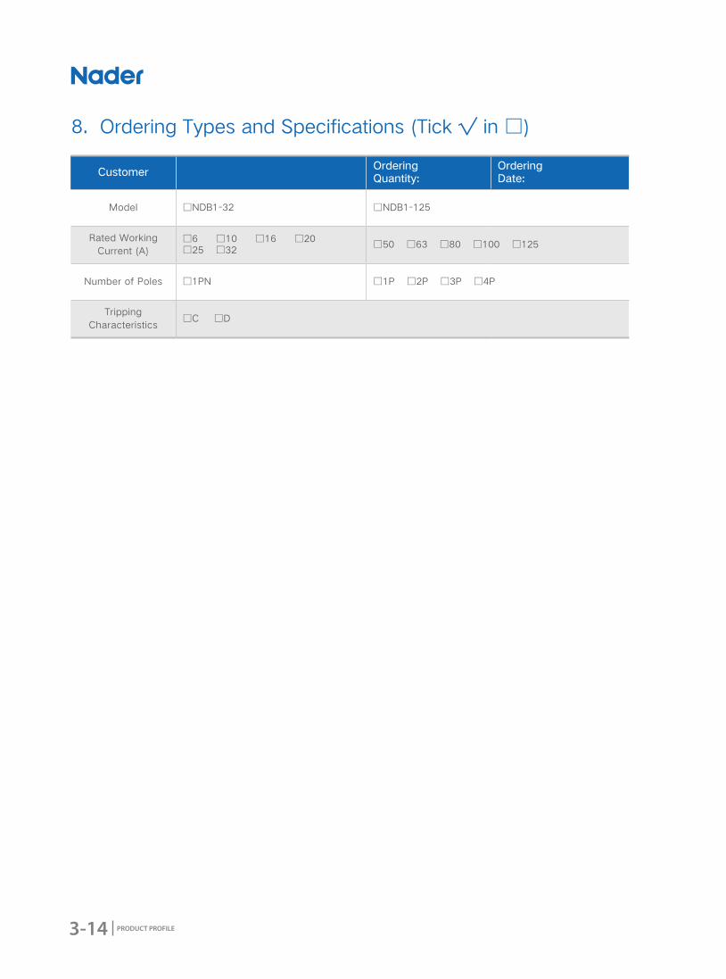
CustomerOrdering Quantity:
Ordering Date:
Model □NDB1-32 □NDB1-125
Rated Working Current (A)
□6 □10 □16 □20 □25 □32
□50 □63 □80 □100 □125
Number of Poles □1PN □1P □2P □3P □4P
Tripping Characteristics
□C □D
8. Ordering Types and Specifications (Tick √ in □)

4-1
NDB1L Series RCBO
PRODUCT PROFILE
2016 Edition
NDB1L Series RCBO
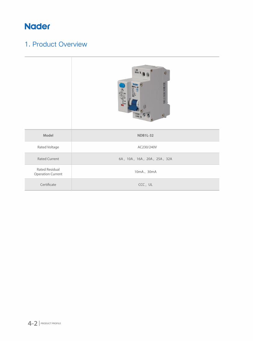
4-2 PRODUCT PROFILE
Model NDB1L-32
Rated Voltage AC230/240V
Rated Current 6A,10A,16A,20A,25A,32A
Rated Residual Operation Current
10mA、30mA
Certi�cate CCC,UL
1. Product Overview
4-3
NDB1L Series RCBO
PRODUCT PROFILE
2. Product Features
● Application ScopeNDB1L-32 RCBO is used in low-voltage terminal distribution for industry, civil building, energy,
telecommunication and construction to do protection from short circuit, overload, leakage and over-
voltage.
● Design FeaturesVisual window's design: Make the product's switching-closing status more clearly to see.
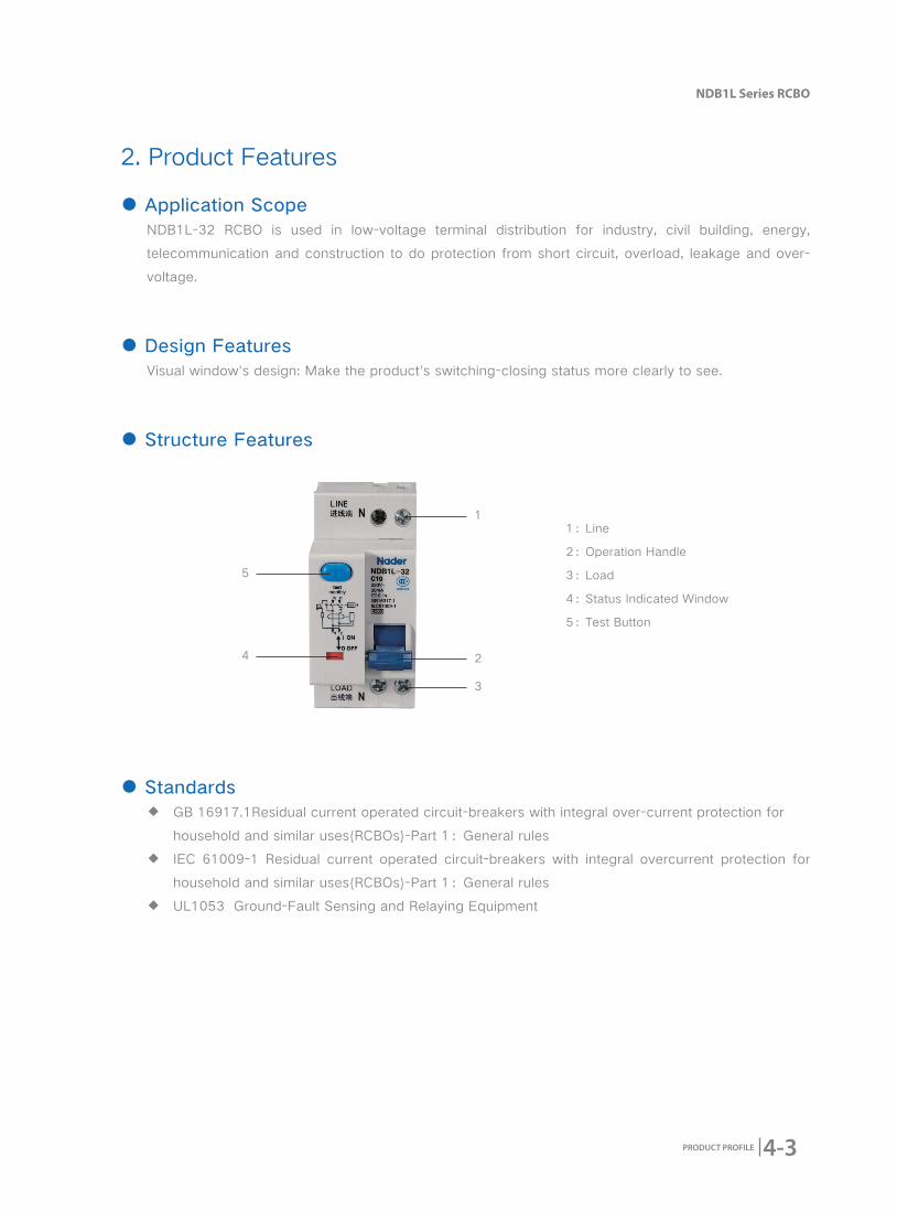
● Structure Features
1:Line
2:Operation Handle
3:Load
4:Status Indicated Window
5:Test Button
5
● Standards ◆ GB 16917.1Residual current operated circuit-breakers with integral over-current protection for
household and similar uses(RCBOs)-Part 1:General rules
◆ IEC 61009-1 Residual current operated circuit-breakers with integral overcurrent protection for
household and similar uses(RCBOs)-Part 1:General rules
◆ UL1053 Ground-Fault Sensing and Relaying Equipment
1
2
3
4
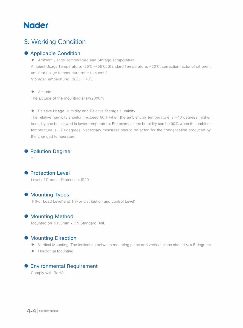
4-4 PRODUCT PROFILE
3. Working Condition
● Applicable Condition ◆ Ambient Usage Temperature and Storage Temperature
Ambient Usage Temperature: -25℃~+55℃, Standard Temperature: +30℃, correction factor of different
ambient usage temperature refer to sheet 1
Storage Temperature: -30℃~+70℃.
◆ Altitude
The altitude of the mounting site≤2000m
◆ Relative Usage Humidity and Relative Storage Humidity
The relative humidity shouldn't exceed 50% when the ambient air temperature is +40 degrees, higher
humidity can be allowed in lower temperature. For example, the humidity can be 90% when the ambient
temperature is +20 degrees. Necessary measures should be acted for the condensation produced by
the changed temperature.
● Pollution Degree2
● Protection LevelLevel of Product Protection: IP20
● Mounting TypesⅡ(For Load Level)and Ⅲ(For distribution and control Level)
● Mounting MethodMounted on TH35mm x 7.5 Standard Rail.
● Mounting Direction ◆ Vertical Mounting: The inclination between mounting plane and vertical plane should ≤±5 degrees
◆ Horizontal Mounting
● Environmental RequirementComply with RoHS

4-5
NDB1L Series RCBO
PRODUCT PROFILE
No. Implication Instruction
1 Brand Code ND:
2 Model B:MCB
3 Design Code 1
4 Electric Leakage L Leakage Functional Code
5Over-Voltage
Functional CodeG: Over-Voltage Protective Function. There is no Over-Voltage Protective Function if there is no "G"
6 Frame Rating 32A
7Instantaneous Tripping
CharacteristicC: Instantaneous Tripping Range 5In~10In
8 Rated Current 6A,10A,16A,20A,25A,32A
9 Number of Poles 1PN
4. Product Technical Characteristic
4.1 Model and Implication
ND 32- /1 LB
1 2 3 54 6 87 9
4-6 PRODUCT PROFILE
4.2 Technical Parameters
NDB1L-32
Rated Voltage (Ue) AC230/240V(1PN)
Rated Current (Ie) 6A、10A、16A、20A、25A、32A
Tripping Characteristics of Residual Current
AC, ELE
Rated Residual Operation Current (IΔn)
10mA、30mA
Rated Insulated Voltage (Ui) AC500V
Rated Impulse Withstand Voltage (Uimp)
4kV
Rated Ultimated Short-Circuit Breaking Current (Icu)
4.5kA;6kA (UL1053)
Rated Short-Circuit Operation Breaking Current (Ics)
4.5kA;6kA (UL1053)
Rated Residual Connecting and Breaking Current (IΔm)
500A
Rated Working Frequency 50/60Hz
Over-Voltage Operation Value and Time (Uover)
280V±12V /0.1s
Mechanical and Electric Life 10000次
Connecting and Wiring Capacity ◆ Tunnel Connecting Terminal ◆ Terminal Connecting Area: 1~10 mm2 cable is applicable ◆ Connecting Screw is M4, Torque is 1.2N.m
4-7
NDB1L Series RCBO
PRODUCT PROFILE
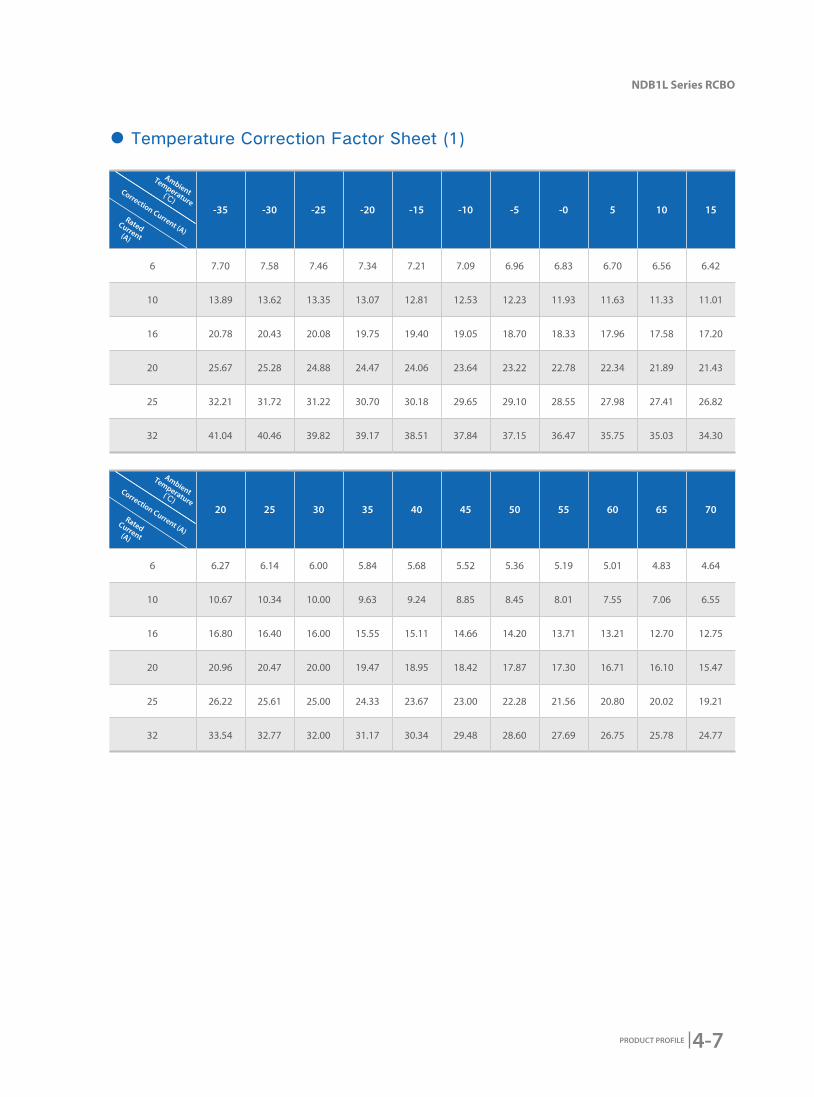
-35 -30 -25 -20 -15 -10 -5 -0 5 10 15
6 7.70 7.58 7.46 7.34 7.21 7.09 6.96 6.83 6.70 6.56 6.42
10 13.89 13.62 13.35 13.07 12.81 12.53 12.23 11.93 11.63 11.33 11.01
16 20.78 20.43 20.08 19.75 19.40 19.05 18.70 18.33 17.96 17.58 17.20
20 25.67 25.28 24.88 24.47 24.06 23.64 23.22 22.78 22.34 21.89 21.43
25 32.21 31.72 31.22 30.70 30.18 29.65 29.10 28.55 27.98 27.41 26.82
32 41.04 40.46 39.82 39.17 38.51 37.84 37.15 36.47 35.75 35.03 34.30
20 25 30 35 40 45 50 55 60 65 70
6 6.27 6.14 6.00 5.84 5.68 5.52 5.36 5.19 5.01 4.83 4.64
10 10.67 10.34 10.00 9.63 9.24 8.85 8.45 8.01 7.55 7.06 6.55
16 16.80 16.40 16.00 15.55 15.11 14.66 14.20 13.71 13.21 12.70 12.75
20 20.96 20.47 20.00 19.47 18.95 18.42 17.87 17.30 16.71 16.10 15.47
25 26.22 25.61 25.00 24.33 23.67 23.00 22.28 21.56 20.80 20.02 19.21
32 33.54 32.77 32.00 31.17 30.34 29.48 28.60 27.69 26.75 25.78 24.77
● Temperature Correction Factor Sheet (1)
Ambient
Temperature(℃)
Correction Current (A)
Rated Current(A)
Ambient
Temperature(℃)
Correction Current (A)
Rated Current(A)

4-8 PRODUCT PROFILE
C Curve ★ Protect nominal load and distribution cables
★ Rated Current: 6A-32A
★ Tripping Characteristics: Instantaneous tripping range 5In~10In
4.3 Tripping Curve

4-9
NDB1L Series RCBO
PRODUCT PROFILE
5. Outline and Mounting Dimension
6. Wiring Diagram
4-10 PRODUCT PROFILE
CustomerOrdering Quantity:
Ordering Date:
Frame Rating □NDB1L-32
Number of Poles □1PN
Rated Working Voltage(V)
□AC230/240 □Other (Depend on Customer)
Rated Working Current(A)
6、10、16、20、25、32
Rated Residual Operation
Current(IΔn)(mA)□10 □30 □Other (Depend on Customer)
Over-Voltage Function
□G □Without Over-Voltage Protective Function
Instantaneous Tripping
Characteristic□C Instantaneous Tripping Range: 5In~10In;Protect Nominal Load and Distribution Cables
Connecting □Upper Wiring □Lower Wiring
7. Ordering Types and Specifications (Tick √ in □)
5-1
NDG1 Series Disconnector
PRODUCT PROFILE
2016 Edition
NDG1 Series Disconnector
5-2 PRODUCT PROFILE
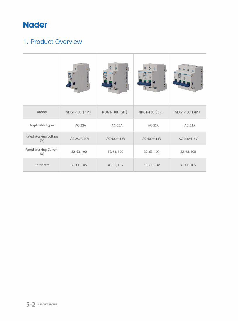
Model NDG1-100(1P) NDG1-100(2P) NDG1-100(3P) NDG1-100(4P)
Applicable Types AC-22A AC-22A AC-22A AC-22A
Rated Working Voltage(V) AC 230/240V AC 400/415V AC 400/415V AC 400/415V
Rated Working Current(A)
32, 63, 100 32, 63, 100 32, 63, 100 32, 63, 100
Certi�cate 3C, CE, TUV 3C, CE, TUV 3C, CE, TUV 3C, CE, TUV
1. Product Overview
5-3
NDG1 Series Disconnector
PRODUCT PROFILE
2. Product Features
● Application ScopeNDG1 Series disconnector can be applicable for usage in the circuits with AC50HZ/60HZ, Rated
Voltage up to 415V and Rated Current up to 100A.And them are often used in the building's circuits
and industrial distribution systems to do the circuits' disconnecting function. Infrequently break-make
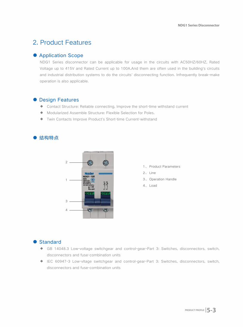
operation is also applicable.
● Design Features ◆ Contact Structure: Reliable connecting, Improve the short-time withstand current
◆ Modularized Assemble Structure: Flexible Selection for Poles.
◆ Twin Contacts Improve Product's Short-time Current-withstand
● 结构特点
1、 Product Parameters
2、 Line
3、 Operation Handle
4、 Load
1
● Standard ◆ GB 14048.3 Low-voltage switchgear and control-gear-Part 3: Switches, disconnectors, switch,
disconnectors and fuse-combination units
◆ IEC 60947-3 Low-vltage switchgear and control-gear-Part 3: Switches, disconnectors, switch,
disconnectors and fuse-combination units
2
3
4

5-4 PRODUCT PROFILE
3. Working Condition
● Electrical Symbol
● Applicable Condition ◆ Ambient Usage Temperature and Storage Temperature
Ambient Usage Temperature: -35℃-+70℃, the average temperature can't exceed +35℃ within 24h.
◆ Altitude
The altitude of the mounting site≤2000m
◆ Relative Usage Humidity and Relative Storage Humidity
◆ The relative humidity shouldn't exceed 50% when the ambient air temperature is +60 degrees,higher
humidity can be allowed in lower temperature. For example,the humidity can be 80% when the
ambient temperature is +20 degrees. Necessary measures should be acted for the condensation
produced by the changed temperature.
● Pollution Degree2
● Protection LevelLevel of Product Protection: IP20
● Applicable TypesAC-22A
● Mounting TypesⅡ(For Load Level)and Ⅲ(For distribution and control Level)
● Mounting MethodMounted on TH35mm x 7.5 Standard Rail.
● Mounting DirectionVertical Mounting
● Environmental Requirement Comply With RoHS
● Terminal Connecting Area2-35mm2 cable is applicable
5-5
NDG1 Series Disconnector
PRODUCT PROFILE
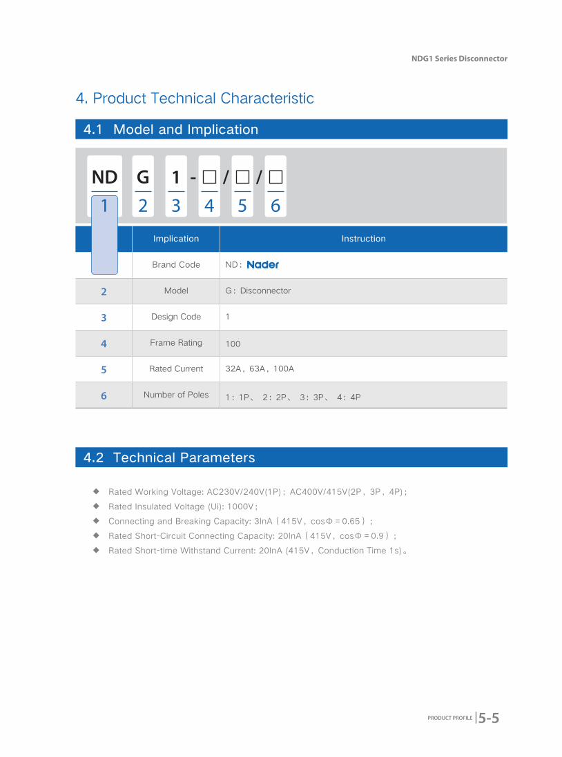
No. Implication Instruction
1 Brand Code ND:
2 Model G:Disconnector
3 Design Code 1
4 Frame Rating 100
5 Rated Current 32A,63A,100A
6 Number of Poles 1:1P、 2:2P、 3:3P、 4:4P
4. Product Technical Characteristic
4.1 Model and Implication
4.2 Technical Parameters
ND - / /1G
1 2 3 54 6
◆ Rated Working Voltage: AC230V/240V(1P);AC400V/415V(2P,3P,4P);
◆ Rated Insulated Voltage (Ui): 1000V;
◆ Connecting and Breaking Capacity: 3InA(415V,cosФ=0.65);
◆ Rated Short-Circuit Connecting Capacity: 20InA(415V,cosФ=0.9);
◆ Rated Short-time Withstand Current: 20InA (415V,Conduction Time 1s)。

5-6 PRODUCT PROFILE
4.3 Specification
Number of Poles Width (mm)Rated Current
(A)Model
18 32 NDG1-100 32/1
18 63 NDG1-100 63/1
18 100 NDG1-100 100/1
36 32 NDG1-100 32/2
36 63 NDG1-100 63/2
36 100 NDG1-100 100/2
54 32 NDG1-100 32/3
54 63 NDG1-100 63/3
54 100 NDG1-100 100/3
72 32 NDG1-100 32/4
72 63 NDG1-100 63/4
72 100 NDG1-100 100/4
5-7
NDG1 Series Disconnector
PRODUCT PROFILE
5.1 Accessory Sheet
NDG1-100 Accessory Types
5.3 Accessory Technical Parameters
5.2 Accessory Functional Instruction
5. Accessory
Parts Function
Auxiliary Contact Connect and monitor the product's switch-closing status synchronously and expand the auxiliary contact's quantity.
No. Name Model Mounting Method
①Auxiliary Contact
OF3Multi-Lateral
(1pcs at most)
OF3 Auxiliary Contact
◆ AC 250V 6A;
◆ AC 415V 3A;
◆ Width(mm): 18;
◆ When it is Closing: 11, 14 means Connecting;
◆ When it is Opening: 11, 12 means Connecting;
◆ Wiring Capacity:≤10mm2 cables;
◆ OF3 Wiring Diagram:
5-8 PRODUCT PROFILE
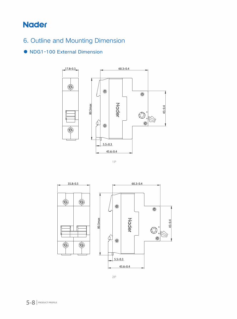
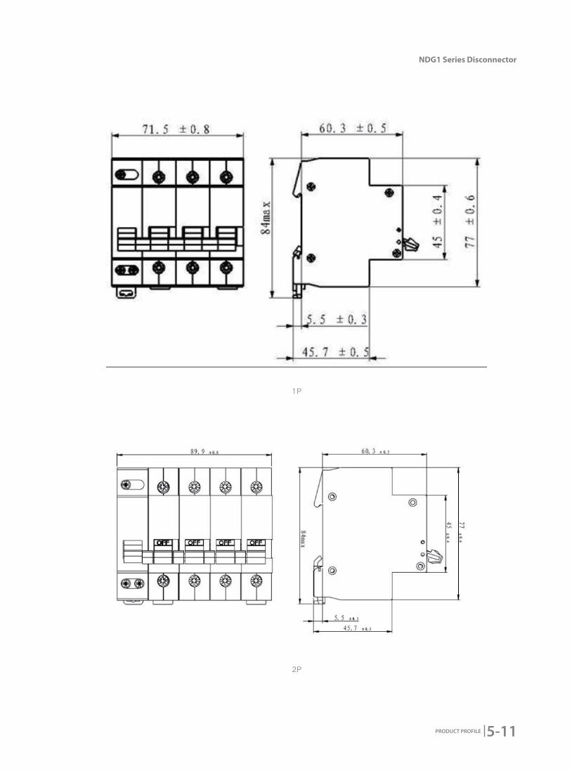
6. Outline and Mounting Dimension
● NDG1-100 External Dimension
1P
2P

5-9
NDG1 Series Disconnector
PRODUCT PROFILE
1P
2P
上海良信电器股份有限公司
5-10 PRODUCT PROFILE
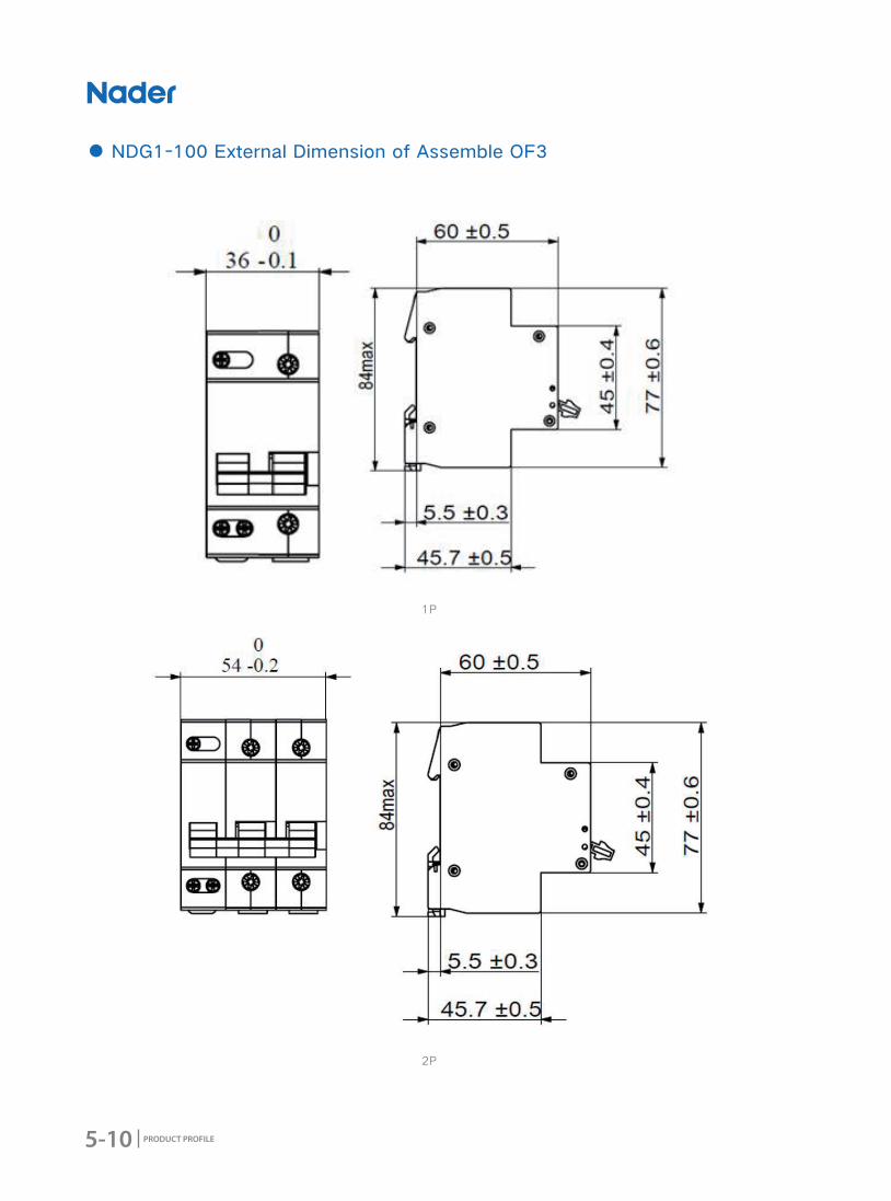
● NDG1-100 External Dimension of Assemble OF3
1P
2P
5-11
NDG1 Series Disconnector
PRODUCT PROFILE
1P
2P
5-12 PRODUCT PROFILE
CustomerOrdering Quantity:
Ordering Date:
Frame Rating □NDG1-100 100/1 □NDG1-100 100/4+OF3
Number of Poles
□1P
□2P
□3P
□4P
7. Wiring Diagram
8. Ordering Types and Specifications (Tick √ in □)
6-1
NDG1-100+NCJ1 Series Disconnector+Conversion Operation Accessory
PRODUCT PROFILE
2016 Edition
NDG1-100+NCJ1 Series Disconnector+Conversion Operation Accessory
6-2 PRODUCT PROFILE
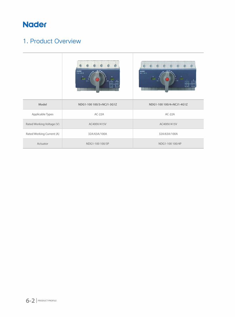
Model NDG1-100 100/3+NCJ1-3G1Z NDG1-100 100/4+NCJ1-4G1Z
Applicable Types AC-22A AC-22A
Rated Working Voltage (V) AC400V/415V AC400V/415V
Rated Working Current (A) 32A/63A/100A 32A/63A/100A
Actuator NDG1-100 100/3P NDG1-100 100/4P
1. Product Overview
6-3
NDG1-100+NCJ1 Series Disconnector+Conversion Operation Accessory
PRODUCT PROFILE
2. Product Features
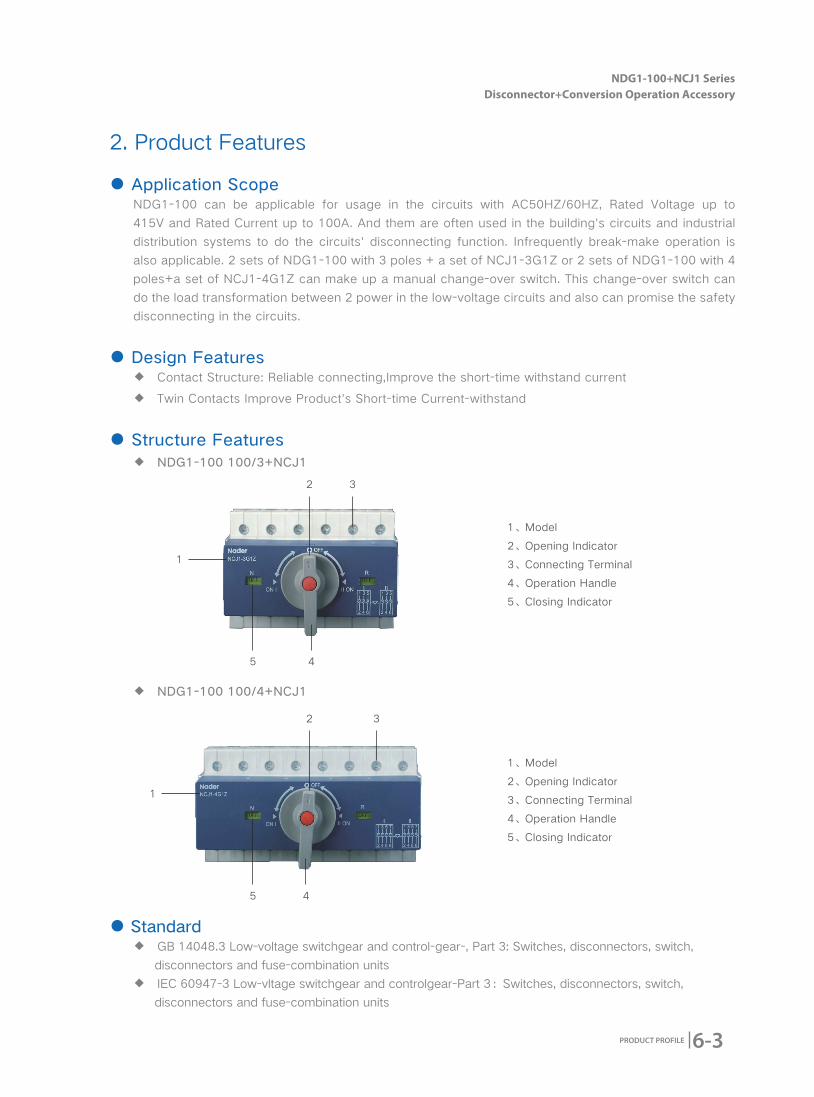
● Application ScopeNDG1-100 can be applicable for usage in the circuits with AC50HZ/60HZ, Rated Voltage up to
415V and Rated Current up to 100A. And them are often used in the building's circuits and industrial
distribution systems to do the circuits' disconnecting function. Infrequently break-make operation is
also applicable. 2 sets of NDG1-100 with 3 poles + a set of NCJ1-3G1Z or 2 sets of NDG1-100 with 4
poles+a set of NCJ1-4G1Z can make up a manual change-over switch. This change-over switch can
do the load transformation between 2 power in the low-voltage circuits and also can promise the safety
disconnecting in the circuits.
● Design Features ◆ Contact Structure: Reliable connecting,Improve the short-time withstand current
◆ Twin Contacts Improve Product's Short-time Current-withstand
● Structure Features ◆ NDG1-100 100/3+NCJ1
1
1
2
2
3
3
4
4
5
5
● Standard ◆ GB 14048.3 Low-voltage switchgear and control-gear-, Part 3: Switches, disconnectors, switch,
disconnectors and fuse-combination units
◆ IEC 60947-3 Low-vltage switchgear and controlgear-Part 3:Switches, disconnectors, switch,
disconnectors and fuse-combination units
◆ NDG1-100 100/4+NCJ1
1、Model
2、Opening Indicator
3、Connecting Terminal
4、Operation Handle
5、Closing Indicator
1、Model
2、Opening Indicator
3、Connecting Terminal
4、Operation Handle
5、Closing Indicator
6-4 PRODUCT PROFILE
3. Working Condition
● Electrical Symbol
● Applicable Condition ◆ Ambient Usage Temperature
Ambient Usage Temperature: -35℃-+70℃, the average temperature can't exceed +35℃ within 24h.
◆ Altitude
The altitude of the mounting site≤2000m
◆ Relative Usage Humidity and Relative Storage Humidity
The relative humidity shouldn't exceed 50% when the ambient air temperature is +60 degrees, higher
humidity can be allowed in lower temperature. For example, the humidity can be 80% when the ambient
temperature is 20 degrees. Necessary measures should be acted for the condensation produced by
the changed temperature.
● Pollution Degree2
● Protection LevelLevel of Product Protection:IP20
● Applicable TypesAC-22A
● Mounting MethodMounted on TH35mm x 7.5 Standard Rail.
● Mounting TypesⅡ(For Load Level) and Ⅲ(For distribution and control Level)
● Mounting Direction Vertical Mounting
● Environmental RequirementComply with RoHS
● Connection ◆ Connecting Screw is M7, Torque is 3.5N.m
◆ Terminal Connecting Area: 2~35 mm2 cable is applicable
◆ Torque of Conversion Operation is 1N.m
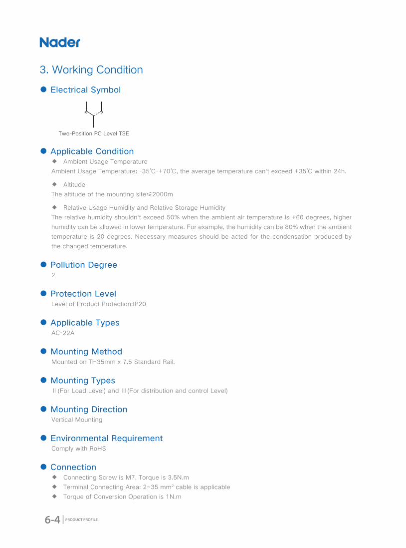
Two-Position PC Level TSE
6-5
NDG1-100+NCJ1 Series Disconnector+Conversion Operation Accessory
PRODUCT PROFILE
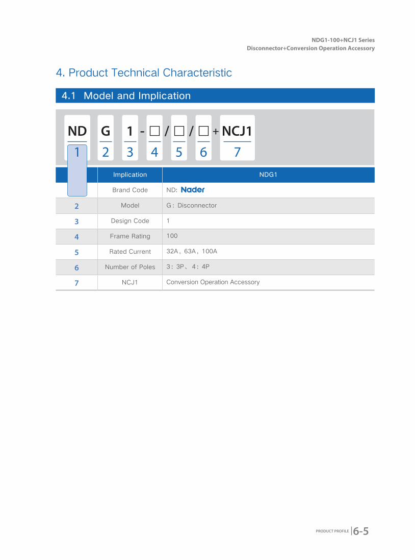
No. Implication NDG1
1 Brand Code ND:
2 Model G:Disconnector
3 Design Code 1
4 Frame Rating 100
5 Rated Current 32A,63A,100A
6 Number of Poles 3:3P、 4:4P
7 NCJ1 Conversion Operation Accessory
4. Product Technical Characteristic
4.1 Model and Implication
ND NCJ1- +//G 1
1 72 3 64 5
6-6 PRODUCT PROFILE
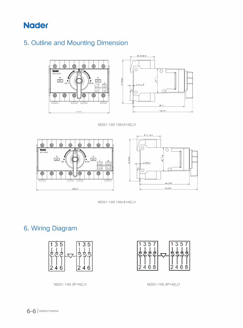
5. Outline and Mounting Dimension
6. Wiring Diagram
NDG1-100 3P+NCJ1 NDG1-100 4P+NCJ1
NDG1-100 100/3+NCJ1
NDG1-100 100/4+NCJ1
6-7
NDG1-100+NCJ1 Series Disconnector+Conversion Operation Accessory
PRODUCT PROFILE
CustomerOrdering Quantity:
Ordering Date:
Frame Rating □NDG1-100 100/3+NCJ1 □NDG1-100 100/4+NCJ1
Number of Poles□3P
□4P
7. Ordering Types and Specifications (Tick √ in □)

6-8 PRODUCT PROFILE
7-1
NDGQ1Z Series OUPA
PRODUCT PROFILE
2016 Edition
NDGQ1Z Series OUPA

7-2 PRODUCT PROFILE
Model NDGQ1Z
Rated Voltage AC220/230V
Rated Current 32A、40A、50A、63A、80A
1. Product Overview
2. Product Features
● Applicable ScopeNDGQ1Z series OUPA can be applicable for usage in the circuits with AC50HZ/60HZ and Rated Voltage
220V or 230V.This series OUPA can be installed in series with Circuit Breaker to protect the circuits
when over-voltage or under-voltage happens;when the circuits get back to normal,the OUPA will switch
on to protect the circuit's normal operation.
OUPA is widely used to do the protection for building and industry distribution systems.
● Design Features ◆ Visual window's design: Make the product's working status more clearly to see.
◆ Standard mounting structure: Easily to remove and mount.
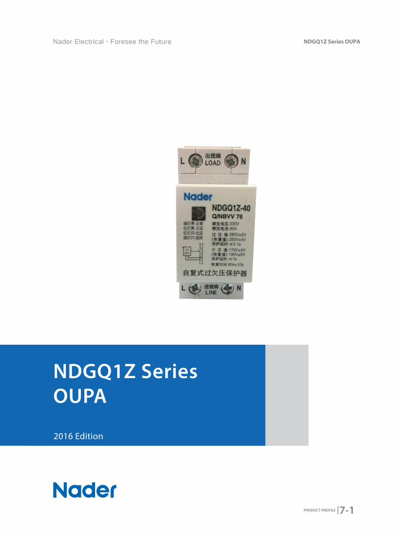
● Structure Features ◆ NDGQ1Z External Diagram
1:Line
2:Load
3:Status Indicated Window
4:Product Parameters
2
4
1
3
7-3
NDGQ1Z Series OUPA
PRODUCT PROFILE
3. Working Condition
● Applicable Condition ◆ Ambient Usage Temperature:
★ Ambient Usage Temperature: -25℃-+55℃, the average temperature can't exceed +35℃ within
24h.A negotiation should be started between customers and manufacturer when the ambient
temperature is lower than -25℃.
★ Storage Temperature: -30℃~+70℃
◆ Altitude
The altitude of the mounting site≤2000m
◆ Relative Usage Humidity and Relative Storage Humidity
The relative humidity shouldn't exceed 50% when the ambient air temperature is +40 degrees,higher
humidity can be allowed in lower temperature. For example,the humidity can be 90% when the ambient
temperature is +20 degrees. Necessary measures should be acted for the condensation produced by
the changed temperature.
● Pollution Degree2
● Protection LevelLevel of Product Protection: IP20
● Mounting MethodMounted on TH35mm x 7.5 Standard Rail.
● Mounting Direction ◆ Vertical Mounting: The inclination between mounting plane and vertical plane should ≤±5 degrees
◆ Horizontal Mounting
● Environmental RequirementComply with RoHS

7-4 PRODUCT PROFILE
No. Implication NDGQ1Z
1 Brand Code ND:
2 Over-Voltage Functional Code G:Protection Function for Over-voltage
3 Under-Voltage Functional Code Q:Protection Function for under-voltage
4 Design Code 1
5 Auto-Reclosing Function Code Z:Auto-Reclosing Function
6 Rated Current 32A,40A,50A,63A,80A
7 NCJ1 Converted Operation Accessory
4. Product Technical Characteristic
4.1 Model and Implication
ND -G Q 1 Z
1 2 3 64 5

7-5
NDGQ1Z Series OUPA
PRODUCT PROFILE
The Green light will twinkle after connecting the normal voltage;twinkling 60+\-10s later, OUPA switches
on and the twinkling green light status will turn into solid green light status means the OUPA going to the
normal working condition. OUPA will switch off together with twinkling red light when OUPA stay in over-
voltage status.; The twinkling red light will turn into twinkling green light after the voltage return to normal
level; Delaying 60+\-10s, OUPA will switch on and turn into solid green light. OUPA will switch off together
with solid red light when OUPA stay in under-voltage status.; The solid red light will turn into twinkling green
light after the voltage return to normal level; Delaying 60+\-10s, OUPA will switch on and turn into solid
green light from twinkling green light.
Indicator status as follow:
4.2 Technical Parameters
4.3 Status Indicator's Instruction
Model NDGQ1Z
Rated Voltage (Ue) AC220/230V
Rated Current (Ie) 32A、40A、50A、63A、80A
Rated Insulated Voltage (Ui) AC440V
Rated Working Frequency (Hz) 50/60
Number of Poles 1PN
Mechanical and Electric Life 7000次
Normal Withstand Voltage (V) AC300V
Withstand Voltage between poles and shell(V) AC2500V
Withstand Voltage among disconnecting contacts(V) AC1500V
Resistance Value between Poles and Shell 5MΩ
Connecting and Wiring Capacity ◆ Tunnel Connecting Terminal ◆ Terminal Connecting Area: 1~25 mm2 cable is applicable ◆ Connecting Screw is M5, Torque is 2.0N.m
4.2.1 Technical Parameters Sheet
4.2.2 Working Parameters Sheet
ModelRated
Voltage(V)
Over-Voltage Under-Voltage Working Time of
Over-Voltage
Working Time of
Under-Voltage
Delay Reseting
TimeWorking
ValueRecovery
ValueWorking
ValueRecovery
Value
NDGQ1Z 220 270V±5V 250V±5V 170V±5V 190V±5V 0.05S≤t≤0.1S 0.5S≤t≤1S 60S±10S
NDGQ1Z 230 280V±5V 250V±5V 170V±5V 190V±5V 0.05S≤t≤0.1S 0.5S≤t≤1S 60S±10S
Solid Red Light Twinkling Red Light Solid Green Light Twinkling Green Light
Under-Voltage Status Over-Voltage Status Normal Working Over/Under-Voltage Delayed Reseting Status
7-6 PRODUCT PROFILE
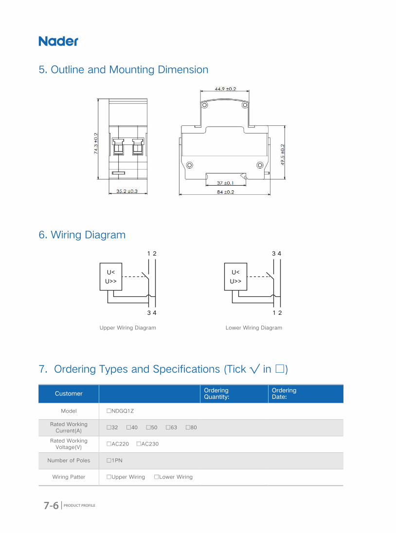
5. Outline and Mounting Dimension
6. Wiring Diagram
Upper Wiring Diagram Lower Wiring Diagram
7. Ordering Types and Specifications (Tick √ in □)
Customer Ordering Quantity:
Ordering Date:
Model □NDGQ1Z
Rated Working Current(A)
□32 □40 □50 □63 □80
Rated Working Voltage(V)
□AC220 □AC230
Number of Poles □1PN
Wiring Patter □Upper Wiring □Lower Wiring
8-1
NDH Series Bus-bar
PRODUCT PROFILE
2016 Edition
NDH Series Bus-bar
8-2 PRODUCT PROFILE
1. Product Overview
2. Product Features
● Applicable ScopeNDH1/NDH2 Bus-bar are the modularized accessory of NDM1-63,NDB2-63 and NDG1. They can be
used to do the same-phase connection among multiple MCB's input terminals and also can do the
connection among the terminal electric equipments with same-phase as a standard accessory.
● Design Features ◆ Bus-bar comprises comb copper bar and insulated sheath.
◆ Bus-bar comprises comb copper bar and insulated sheath.
◆ Impacted structure and easy to use.
● Standard ◆ GB 14048.1 Low-voltage switchgear and controlgear Part 1: General rules
◆ IEC 60947-1 Low-voltage switchgear and controlgear-Part 1:General rules
Model NDH1-63/100 NDH2-63/100
Rated Working Current (A)
Teeth Space (mm)
Rated Current (A)
Working Voltage (V)
Teeth Space (mm)
Rated Current (A)
Working Voltage (V)
18ⅹn 63A/100A 500V 18ⅹn 63A/100A 500V
8-3
NDH Series Bus-bar
PRODUCT PROFILE
3. Working Condition
● Applicable Condition ◆ Ambient Usage Temperature:
★ Ambient Usage Temperature: -25℃-+55℃, the average temperature can't exceed +35℃ within
24h.A negotiation should be started between customers and manufacturer when the ambient
temperature is lower than-25℃.
★ Storage Temperature: -30℃~+70℃
◆ Altitude
The altitude of the mounting site≤2000m
◆ Relative Usage Humidity and Relative Storage Humidity
The relative humidity shouldn't exceed 50% when the ambient air temperature is +60 degrees,higher
humidity can be allowed in lower temperature. For example,the humidity can be 80% when the ambient
temperature is +30 degrees. Necessary measures should be acted for the condensation produced by
the changed temperature.
● Pollution Degree2
● Protection LevelLevel of Product Protection: IP20
● Environmental RequirementComply with RoHS
8-4 PRODUCT PROFILE
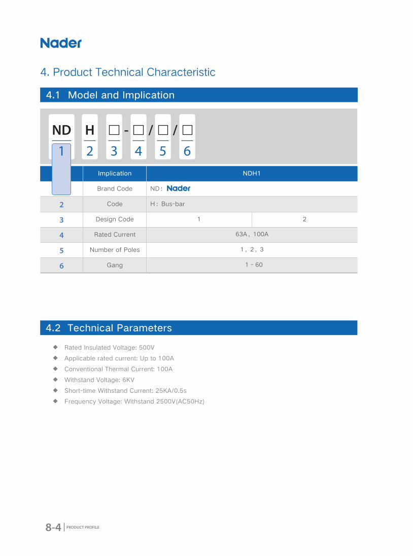
No. Implication NDH1
1 Brand Code ND:
2 Code H:Bus-bar
3 Design Code 1 2
4 Rated Current 63A,100A
5 Number of Poles 1,2,3
6 Gang 1 - 60
4. Product Technical Characteristic
4.1 Model and Implication
ND - / /H
1 2 3 64 5
4.2 Technical Parameters
◆ Rated Insulated Voltage: 500V
◆ Applicable rated current: Up to 100A
◆ Conventional Thermal Current: 100A
◆ Withstand Voltage: 6KV
◆ Short-time Withstand Current: 25KA/0.5s
◆ Frequency Voltage: Withstand 2500V(AC50Hz)
8-5
NDH Series Bus-bar
PRODUCT PROFILE
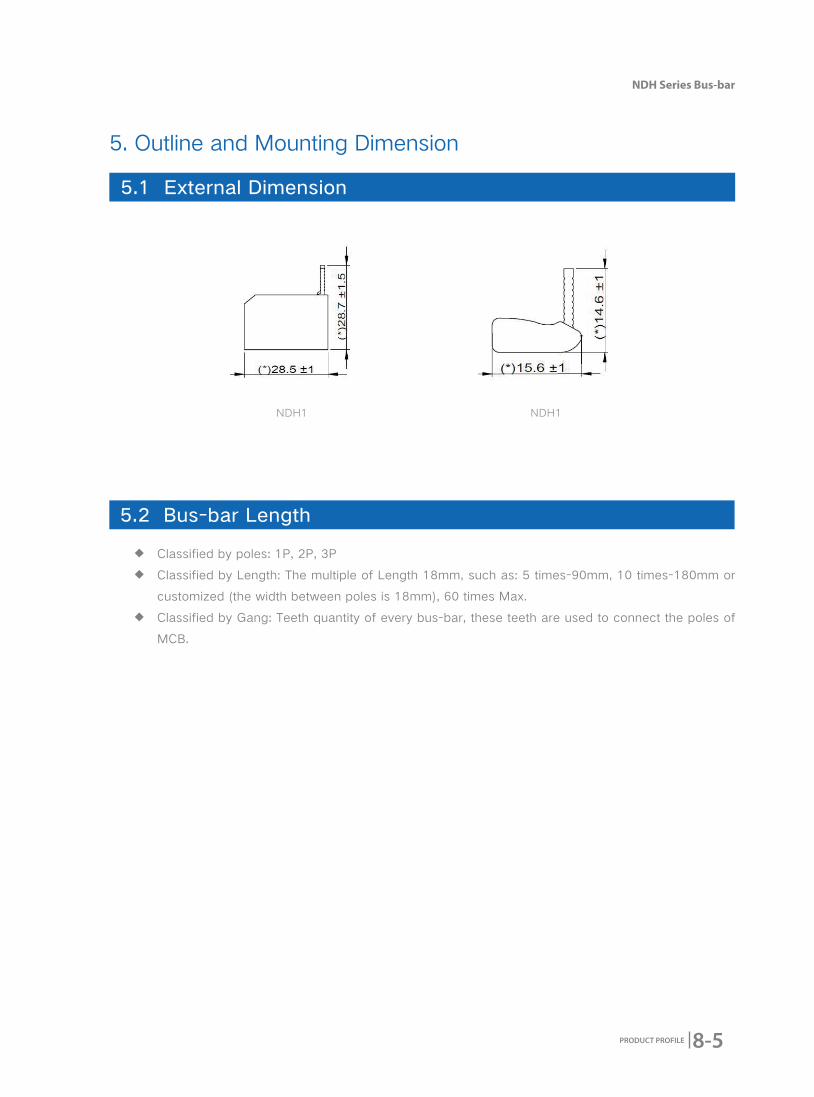
5.1 External Dimension
5.2 Bus-bar Length
◆ Classified by poles: 1P, 2P, 3P
◆ Classified by Length: The multiple of Length 18mm, such as: 5 times-90mm, 10 times-180mm or
customized (the width between poles is 18mm), 60 times Max.
◆ Classified by Gang: Teeth quantity of every bus-bar, these teeth are used to connect the poles of
MCB.
5. Outline and Mounting Dimension
NDH1 NDH1

8-6 PRODUCT PROFILE
Customer Ordering Quantity:
Ordering Date:
Frame Rating □NDH1-63/100 □NDH2-63/100
Number of Poles
□1P □1P
□2P □2P
□3P □3P
Gang 1~60
Accessory (Option) Connector(30008300)
6. Ordering Types and Specifications (Tick √ in □)
9-1
NDA Series Outlet
PRODUCT PROFILE
2016 Edition
NDA Series Outlet
9-2 PRODUCT PROFILE
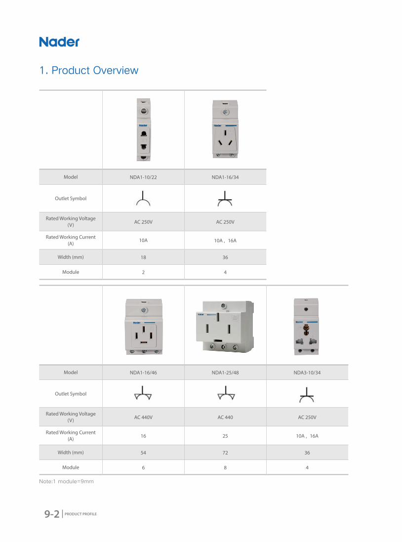
Model NDA1-10/22 NDA1-16/34
Outlet Symbol
Rated Working Voltage (V) AC 250V AC 250V
Rated Working Current (A)
10A 10A,16A
Width (mm) 18 36
Module 2 4
Model NDA1-16/46 NDA1-25/48 NDA3-10/34
Outlet Symbol
Rated Working Voltage (V) AC 440V AC 440 AC 250V
Rated Working Current (A) 16 25 10A,16A
Width (mm) 54 72 36
Module 6 8 4
Note:1 module=9mm
1. Product Overview

9-3
NDA Series Outlet
PRODUCT PROFILE
2. Product Features
● Applicable ScopeThis Series Outlet can be used indoor or outdoor, household and similar sites. Only for AC, Rated current
should not exceed 25A and Rated Voltage Range is: 50V-440V.
● Design Features ◆ This Series Outlet is installed in the modularized distribution box and other electric cabinet to
connect related electric device.
◆ Seriation Product, Modularization.
● Standard ◆ GB 2099.1 Plug and socket-outlets for household and similar purposes-Part 1: General requirements.
◆ IEC 60884-1 Piuge and socket-outlets for household and similar purposes-Part 1: Genenral
requirements.
3. Working Condition
● Applicable Condition ◆ Ambient Usage Temperature and Storage Temperature
Ambient Usage Temperature: -5℃-+40℃
◆ Altitude
The altitude of the mounting site≤2000m
◆ Relative Usage Humidity and Relative Storage Humidity
The relative humidity shouldn't exceed 50% when the ambient air temperature is +60 degrees, higher
humidity can be allowed in lower temperature. For example, the humidity can be 90% when the ambient
temperature is +20 degrees. Necessary measures should be acted for the condensation produced by
the changed temperature.
● Pollution Degree2
● Protection Level Level of Product Protection: IP20
9-4 PRODUCT PROFILE
● Mounting TypesⅡ(For Load Level)and Ⅲ(For distribution and control Level)
● Applicable TypesAC-22A
● Applicable Types Ⅱ(For Load Level) and Ⅲ(For distribution and control Level)
● Mounting MethodMounted on TH35mm x 7.5 Standard Rail.
● Mounting DirectionMounting Direction
● Environmental RequirementComply with RoHS

9-5
NDA Series Outlet
PRODUCT PROFILE
4. Product Technical Characteristic
4.1 Model and Implication
No. Implication NDA
1 Brand Code ND:
2 Code A: Outlet
3 Design Code 1 3
4 Rated Current 10A,16A,25A 10A,16A
5 Holes 2,3,4 3
6 Width Module 2,4,6,8 4
ND - / /A
1 2 3 4 5 6
4.2 Technical Characteristics
Model NDA1-10/22 NDA1-16/34 NDA1-16/46 NDA1-25/48 NDA3-10/34
Rated Voltage AC250V AC250V AC250V AC440V AC250V
Rated Current 10A 10A 16A 25A 10A
Holes 2 3 4 3
Width Module 2 4 6 8 4
Terminal Connecting Area
2~25 mm2 cable is applicable
2~25 mm2 cable is applicable
2~25 mm2 cable is applicable1~6 mm2 cable is
applicable

9-6 PRODUCT PROFILE
5. Outline and Mounting Dimension
5.1 NDA1(External Dimension of 2 Holes)
5.2 NDA1-16/34(External Dimension of 3 Holes)
9-7
NDA Series Outlet
PRODUCT PROFILE
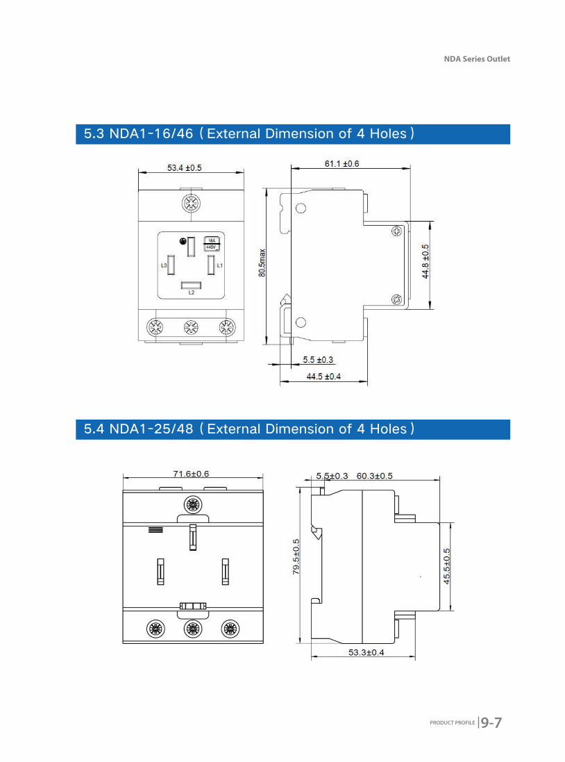
5.3 NDA1-16/46(External Dimension of 4 Holes)
5.4 NDA1-25/48(External Dimension of 4 Holes)
9-8 PRODUCT PROFILE
5.5 NDA3-16/34 (External Dimension of 3 Holes)
Customer Ordering Quantity:
Ordering Date:
Frame Rating □NDA1-10/22 □NDA1-10/34 □NDA1-16/46 □NDA1-25/48 □NDA3-16/34
Number of Holes □2 Holes □3 Holes □4 Holes
6. Ordering Types and Specifications (Tick √ in □)

10-1
NDM1L (NDM1) Series RCBO
PRODUCT PROFILE
2016 Edition
NDM1L (NDM1) Series RCBO
10-2 PRODUCT PROFILE
Model NDM1L-32 NDM1L-50 NDM1L-100
Rated Voltage
AC230/240V(1PN、2P)
AC380/400/
415V(3PN、3P、4P)
AC230/240V(1PN、2P)
AC380/400/
415V(3PN、3P、4P)
AC230V(1PN、2P、3PN、4P)
AC400V(3P)
Rated Current
1A、2A、3A、4A、5A、
6A、10A、16A、20A、
25A、32A
6A、10A、16A、20A、
25A、32A、40A、50A、
10A、16A、20A、25A、
32A、40A、50A
50A、63A、80A、100A
Rated Residual Operation Current
30mA、50mA、
100mA、300mA
30mA、50mA、
100mA、300mA100mA
1. Product Overview
2. Product Features
● Applicable ScopeNDM1L-32, NDM1L-50 and NDM1L-100 Series RCBOs are linked to the right side of both NDM1-63
and NDM1-125. These series RCBOs can protect people from direct or indirect electric shock,protect
the circuits from earth leakage. RCBOs are widely used in Low-voltage distribution of industry, civil
building, energy, telecommunication and infrastructure etc. to protect the circuits from short circuits,
over-current, leakage, disconnection and over/under-voltage.
● Design Features ◆ Visual window's design: Make the product's switching-closing status more clearly to see.
◆ Modularized and Assemble Structure: Easily to remove and mount.

10-3
NDM1L (NDM1) Series RCBO
PRODUCT PROFILE
● Standard ◆ Standard As Follow:
★ GB 16917.1 Residual current operated circuit-breakers with integral over-current protection for
household and similar uses(RCBOs)-Part 1:General rules
★ IEC 61009-1 Residual current operated circuit-breakers with integral overcurrent protection for
household and similar uses(RCBOs)-Part 1:General rules
◆ NDM1L-100 Standard As Follow:
★ GB 14048.2 Low-voltage switchgear and control gear Part 2:Circu it-breakers
★ IEC 60947-2 Low-voltage switchgear and controlgear-Part 2:Circuit-breakers
◆ NDM1L-100 External Diagram
NDM1L-32、50 External Structure Diagram:
1:Line
2:Test Button
3:Operation Handle
4:Reset Button
5:Load
NDM1L-100 External Diagram:
1:Line
2:Test Button
3:Operation Handle
4:Reset Button
5:Load
6:Status Indicated Window
1
1
6
2
2
3
3
4
4
5
5
● Structure Features ◆ NDM1L-32、50 External Diagram
10-4 PRODUCT PROFILE
3. Working Condition
● Applicable Condition ◆ Ambient Usage Temperature and Storage Temperature
Ambient Usage Temperature: -25℃~+55℃, Standard Temperature: +30℃, correction factor of different
ambient usage temperature refer to sheet 1
Storage Temperature:-30℃~+70℃.
◆ Altitude
The altitude of the mounting site≤2000m
◆ Relative Usage Humidity and Relative Storage Humidity
The relative humidity shouldn't exceed 50% when the ambient air temperature is +40 degrees, higher
humidity can be allowed in lower temperature. For example, the humidity can be 90% when the ambient
temperature is +20 degrees. Necessary measures should be acted for the condensation produced by
the changed temperature.
● Pollution Degree2
● Protection Level Level of Product Protection: IP20
● Mounting MethodMounted on TH35mm x 7.5 Standard Rail.
● Mounting Direction ◆ Vertical Mounting: The inclination between mounting plane and vertical plane should ≤±5 degrees
◆ Horizontal Mounting
● Environmental RequirementComply with RoHS

10-5
NDM1L (NDM1) Series RCBO
PRODUCT PROFILE
4. Product Technical Characteristic
4.1 Model and Implication
No. Implication NDM1L
1 Brand Code ND:
2 Code M:MCB
3 Design Code 1
4 Leakage
L: Leakage Functional Code(30mA,50mA,100mA,300mA)
L: Leakage Functional Code(30mA,50mA,100mA,300mA)
L: Leakage Functional Code(100mA)
5 Frame Rating 32A 50A 100A
6Instantaneous
Tripping Characteristics
B: Instantaneous Tripping Range3In~5In;
C: Instantaneous Tripping Range5In~10In;
D: Instantaneous Tripping Range10In~14In;
B: Instantaneous Tripping Range3In~5In;
C: Instantaneous Tripping Range5In~10In;
D: Instantaneous Tripping Range10In~14In;
C: Instantaneous Tripping Range8In(1±20%);
D: Instantaneous Tripping Range12In(1±20%);
7 Rated Current1A,2A,3A,4A,6A,10A,16A,20A,25A,32A
6A,10,16A,20A,25A,32A,40A,50A
50A,63A,80A,100A
8Over-Voltage and
Under-Voltage Functional Code
/
No Code: Normal Leakage Products
GQ:Indicates over-voltage and under-voltage protective function
G: Indicates over-voltage protective function
Q: Indicates under-voltage protective function
No Code: Normal Leakage Products
GQ:Indicates over-voltage and under-voltage protective function
G: Indicates over-voltage protective function
Q: Indicates under-voltage protective function
9 Number of Poles1PN、2P、3P3PN、4P
1PN、2P、3P3PN、4P
1PN、2P、3P3PN、4P
ND - /1 LM
1 2 3 74 8 965

10-6 PRODUCT PROFILE
4.2 Technical Parameters
NDM1L-32 NDM1L-50 NDM1L-100
Rated Voltage (V)
AC230/240V(1PN、2P)
AC380/400/
415V(3PN、3P、4P)
AC230/240V(1PN、2P)
AC380/400/
415V(3PN、3P、4P)
AC230V(1PN、2P、3PN、4P)
AC400V(3P)
Rated Current (A)1、2、3、4、5、6、
10、16、20、25、32
6、10、16、20、25、
32、40、5050、63、80、100
Tripping Characteristics of Residual Current
AC and ELE AC and ELE AC and ELE
Rated Residual Operation Current IΔn (mA)
30、50、100、300 30、50、100、300 100
Rated Insulated Voltage (V) AC500V AC500V AC500V
Rated Ultimate Short Circuit Breaking Current Icu
6kA (B、C)
4.5kA(D)
6kA (B、C6A~40A);
4.5kA(B、C50A、D)10kA
Rated Short-Circuit Operation Breaking Current (Ics)
6kA (B、C)
4.5kA(D)
6kA(B、C6A~40A);
4.5kA(B、C50A、D)10kA
Rated Residual Connecting and Breaking Current (IΔm)
500A 500A 2500A
Rated Working Frequency (Hz) 50/60 50/60 50/60
Over-Voltage Operation Value and Time (Uover)
/ 280V±12V/0.1s 280V±12V/0.1s
Under-Voltage Operation Value and Time (Uover)
/ 170V±7V/1s 170V±7V/1s
Mechanical and Electric Life 20000 20000 20000
Connecting and Wiring
Capacity
◆ Tunnel Connecting Terminal ◆ Terminal Connecting Area: 1~10 mm2 cable is applicable
◆ Connecting Screw is M4, Torque is 1.2N.m
◆ Tunnel Connecting Terminal ◆ Terminal Connecting Area: 1~10 mm2 cable is applicable
◆ Connecting Screw is M4, Torque is 1.2N.m
◆ Tunnel Connecting Terminal ◆ Terminal Connecting Area: 1~50 mm2 cable is applicable
◆ Connecting Screw is M6, Torque is 4.0N.m
Certi�cate CCC CCC CCC

10-7
NDM1L (NDM1) Series RCBO
PRODUCT PROFILE
-35 -30 -25 -20 -15 -10 -5 -0 5 10 15
1 1.27 1.25 1.23 1.21 1.19 1.17 1.15 1.13 1.10 1.08 1.06
3 3.89 3.83 3.76 3.70 3.64 3.57 3.50 3.44 3.37 3.30 3.22
6 7.70 7.58 7.46 7.34 7.21 7.09 6.96 6.83 6.70 6.56 6.42
10 13.89 13.62 13.35 13.07 12.81 12.53 12.23 11.93 11.63 11.33 11.01
16 20.78 20.43 20.08 19.75 19.40 19.05 18.70 18.33 17.96 17.58 17.20
20 25.67 25.28 24.88 24.47 24.06 23.64 23.22 22.78 22.34 21.89 21.43
25 32.21 31.72 31.22 30.70 30.18 29.65 29.10 28.55 27.98 27.41 26.82
32 41.04 40.46 39.82 39.17 38.51 37.84 37.15 36.47 35.75 35.03 34.30
40 51.63 50.86 50.04 40.21 48.37 47.51 46.63 45.74 44.83 43.90 42.95
50 64.92 63.97 62.92 61.86 60.77 59.67 58.54 57.40 56.23 55.05 53.81
63 83.48 82.06 80.64 79.19 77.72 76.22 74.70 73.14 71.54 69.91 68.24
80 135 130 126 122 118 115 112 108 104 99 95
100 160 155 150 146 142 137 133 129 125 122 118
20 25 30 35 40 45 50 55 60 65 70
1 1.05 1.02 1.00 0.97 0.94 0.91 0.89 0.86 0.83 0.80 0.77
3 3.14 3.06 3.00 2.92 2.84 2.76 2.67 2.58 2.49 2.38 2.27
6 6.27 6.14 6.00 5.84 5.68 5.52 5.36 5.19 5.01 4.83 4.64
10 10.67 10.34 10.00 9.63 9.24 8.85 8.45 8.01 7.55 7.06 6.55
16 16.80 16.40 16.00 15.55 15.11 14.66 14.20 13.71 13.21 12.70 12.75
20 20.96 20.47 20.00 19.47 18.95 18.42 17.87 17.30 16.71 16.10 15.47
25 26.22 25.61 25.00 24.33 23.67 23.00 22.28 21.56 20.80 20.02 19.21
32 33.54 32.77 32.00 31.17 30.34 29.48 28.60 27.69 26.75 25.78 24.77
40 41.98 40.99 40.00 38.93 37.85 36.75 35.61 34.43 33.21 31.95 30.63
50 52.56 51.28 50.00 47.82 46.24 44.81 43.33 41.81 40.23 38.58 35.77
63 66.53 64.78 63.00 60.11 58.19 56.21 54.16 52.03 49.81 47.50 43.05
80 91 88 85 82 80 75.5 72.5 68 64.5 58 52.5
100 114 111 108 103 100 94 88 82 75 68 58
● Temperature Correction Factor Sheet (1)
Ambient
Temperature(℃)
Correction Current (A)
Rated Current(A)
Ambient
Temperature(℃)
Correction Current (A)
Rated Current(A)
10-8 PRODUCT PROFILE
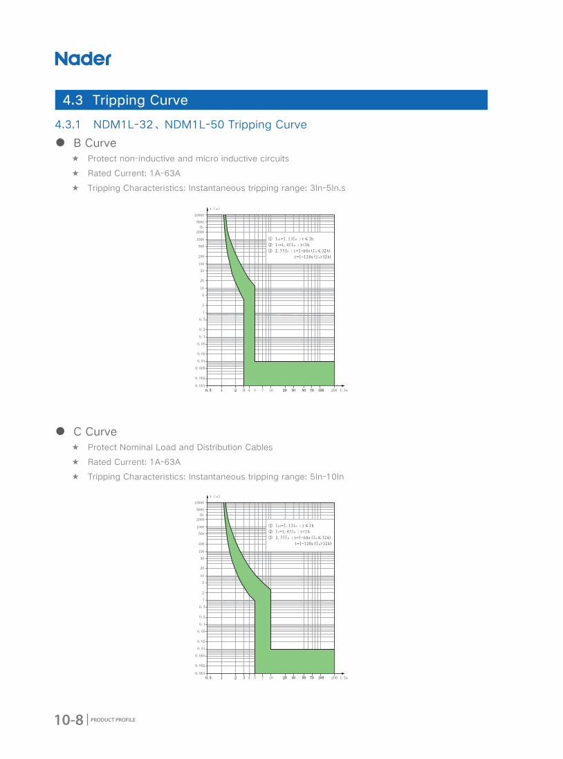
4.3.1 NDM1L-32、NDM1L-50 Tripping Curve
● B Curve ★ Protect non-inductive and micro inductive circuits
★ Rated Current: 1A-63A
★ Tripping Characteristics: Instantaneous tripping range: 3In-5In.s
● C Curve ★ Protect Nominal Load and Distribution Cables
★ Rated Current: 1A-63A
★ Tripping Characteristics: Instantaneous tripping range: 5In-10In
4.3 Tripping Curve

10-9
NDM1L (NDM1) Series RCBO
PRODUCT PROFILE
4.3.2 NDM1L-100 Tripping Curve
● C Curve ★ Protect Nominal Load and Distribution Cables
★ Rated Current: 50A-100A
★ Tripping Characteristics: Instantaneous tripping range: 8In(1±20%)
● D Curve ★ Protect industrial distribution systems
★ Rated Current: 1A-63A
★ Tripping Characteristics: Instantaneous tripping range: 10In-14In
10-10 PRODUCT PROFILE
● D Curve ★ Protect industrial distribution systems
★ Rated Current: 50A-100A
★ Tripping Characteristics: Instantaneous tripping range: 12In(1±20%)

10-11
NDM1L (NDM1) Series RCBO
PRODUCT PROFILE
5. Accessory
Note: Accessory parameters, please refer to "OF、SD" specimens.
NDM1L-32、NDM1L-50、NDM1L-100 Accessory Types
No. Name Accessory Code Function and Matched Quantity
1 Auxiliary Contact OFLinked to the left side of MCB to indicate OPEN or CLOSE status of the associated breaker. Matched quantity: Max 3 Pcs
2 Alarm Contact SDLinked to the left side of MCB to indicate the accidental tripping status of the associated breaker. Matched quantity: 3 Pcs Max.
Auxiliary Contact OF
Alarm Contact SD
10-12 PRODUCT PROFILE
6. Outline and Mounting Dimension
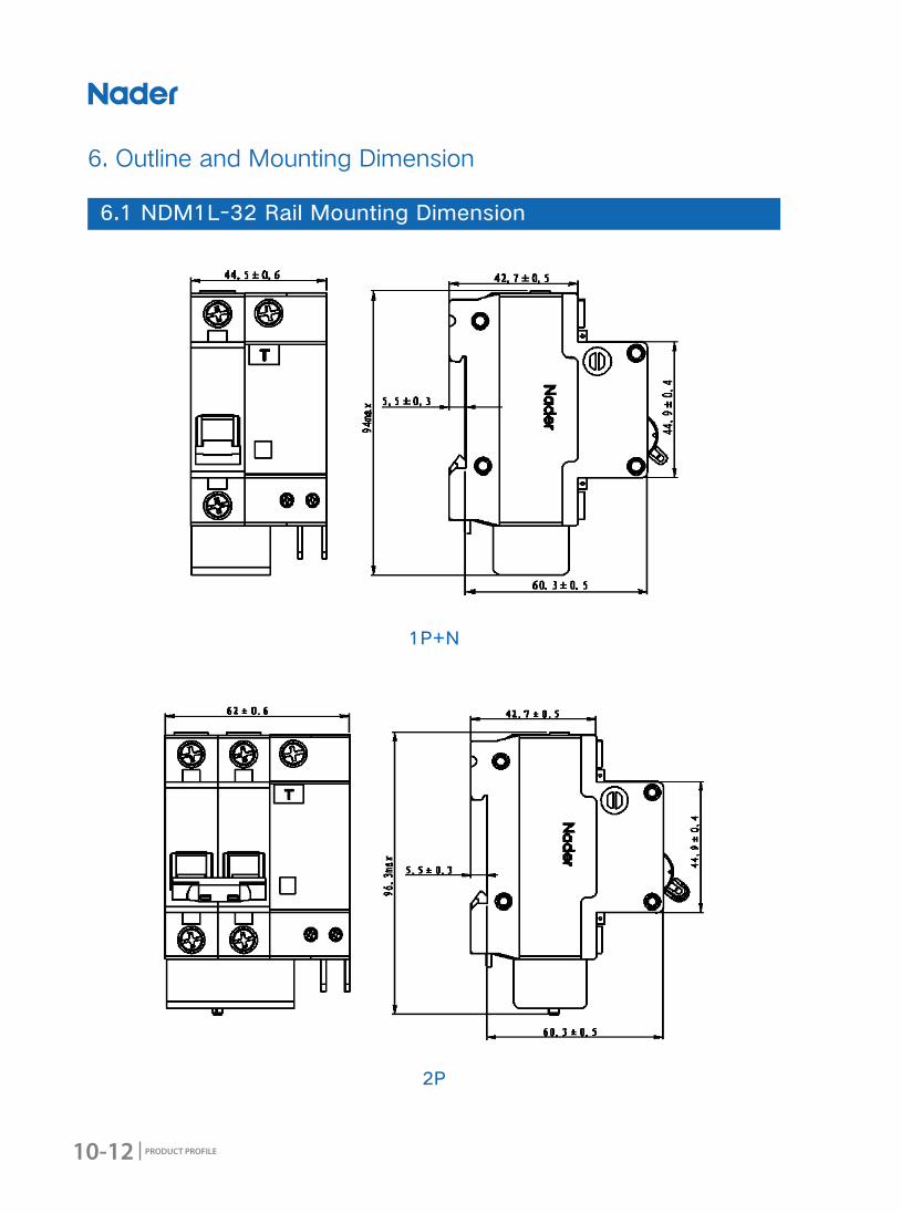
6.1 NDM1L-32 Rail Mounting Dimension
1P+N
2P
10-13
NDM1L (NDM1) Series RCBO
PRODUCT PROFILE
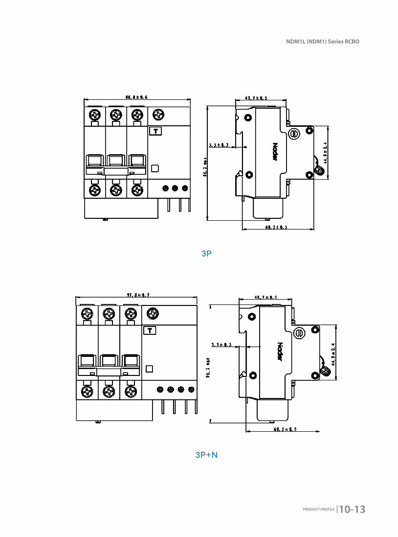
3P+N
3P

10-14 PRODUCT PROFILE
6.2 NDM1L-50 Rail Mounting Dimension
4P
1PN
10-15
NDM1L (NDM1) Series RCBO
PRODUCT PROFILE
2P
3P
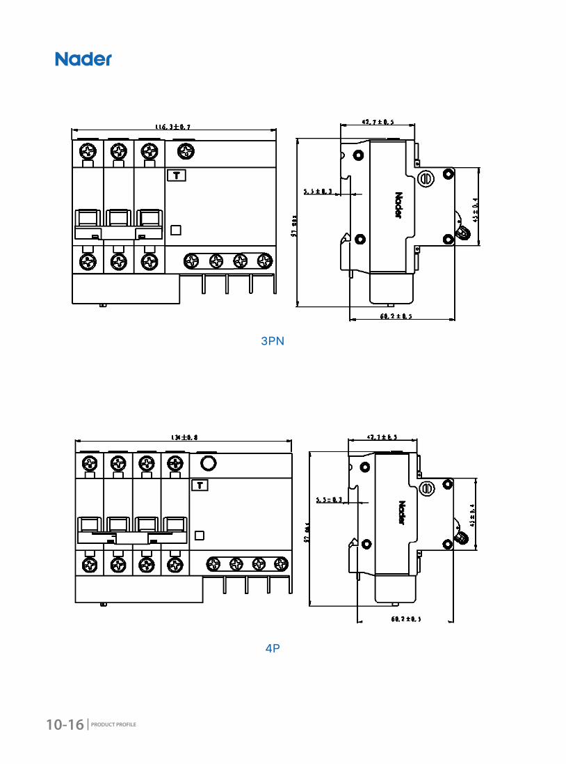
10-16 PRODUCT PROFILE
3PN
4P

10-17
NDM1L (NDM1) Series RCBO
PRODUCT PROFILE
1PN
2P
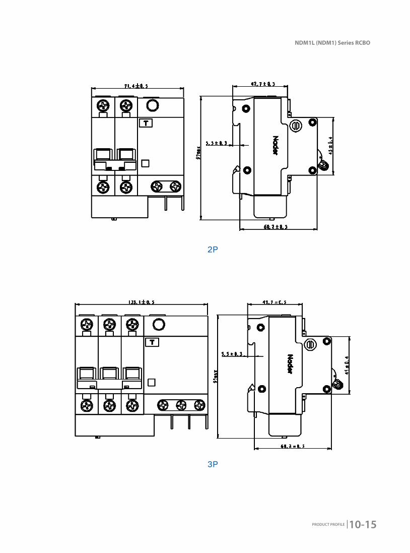
6.3 NDM1L-100 Rail Mounting Dimension

10-18 PRODUCT PROFILE
4P
3PN
3P
10-19
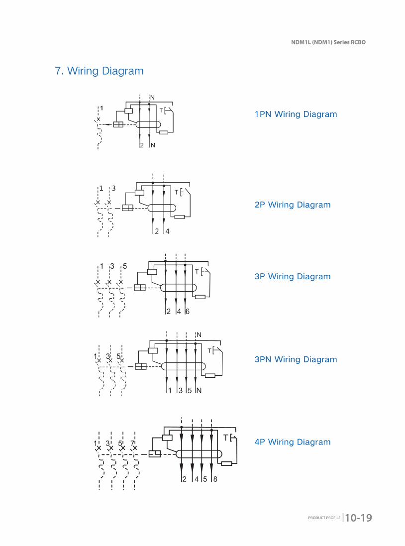
NDM1L (NDM1) Series RCBO
PRODUCT PROFILE
1PN Wiring Diagram
2P Wiring Diagram
3P Wiring Diagram
3PN Wiring Diagram
4P Wiring Diagram
7. Wiring Diagram
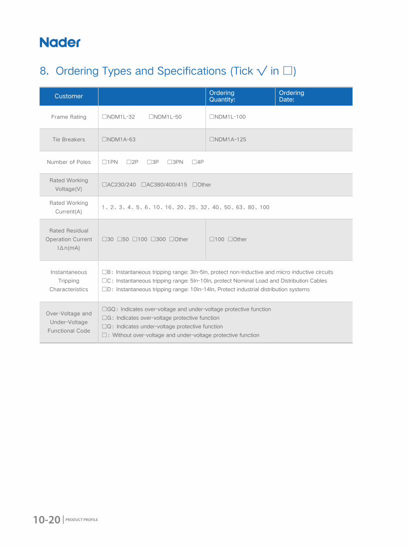
10-20 PRODUCT PROFILE
Customer Ordering Quantity:
Ordering Date:
Frame Rating □NDM1L-32 □NDM1L-50 □NDM1L-100
Tie Breakers □NDM1A-63 □NDM1A-125
Number of Poles □1PN □2P □3P □3PN □4P
Rated Working
Voltage(V)□AC230/240 □AC380/400/415 □Other
Rated Working
Current(A)1、2、3、4、5、6、10、16、20、25、32、40、50、63、80、100
Rated Residual
Operation Current
IΔn(mA)
□30 □50 □100 □300 □Other □100 □Other
Instantaneous
Tripping
Characteristics
□B:Instantaneous tripping range: 3In-5In, protect non-inductive and micro inductive circuits
□C:Instantaneous tripping range: 5In-10In, protect Nominal Load and Distribution Cables
□D:Instantaneous tripping range: 10In-14In, Protect industrial distribution systems
Over-Voltage and
Under-Voltage
Functional Code
□GQ:Indicates over-voltage and under-voltage protective function
□G:Indicates over-voltage protective function
□Q:Indicates under-voltage protective function
□:Without over-voltage and under-voltage protective function
8. Ordering Types and Specifications (Tick √ in □)
11-1
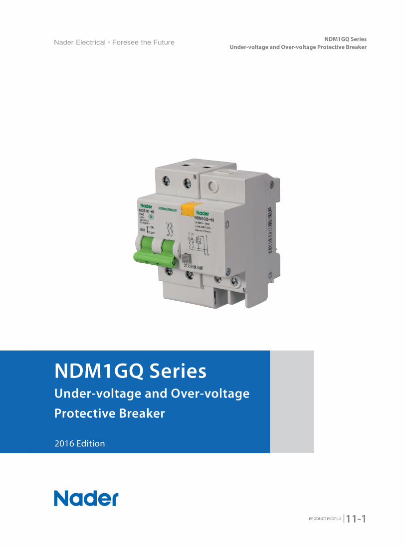
NDM1GQ Series Under-voltage and Over-voltage Protective Breaker
PRODUCT PROFILE
2016 Edition
NDM1GQ Series Under-voltage and Over-voltage
Protective Breaker
11-2 PRODUCT PROFILE
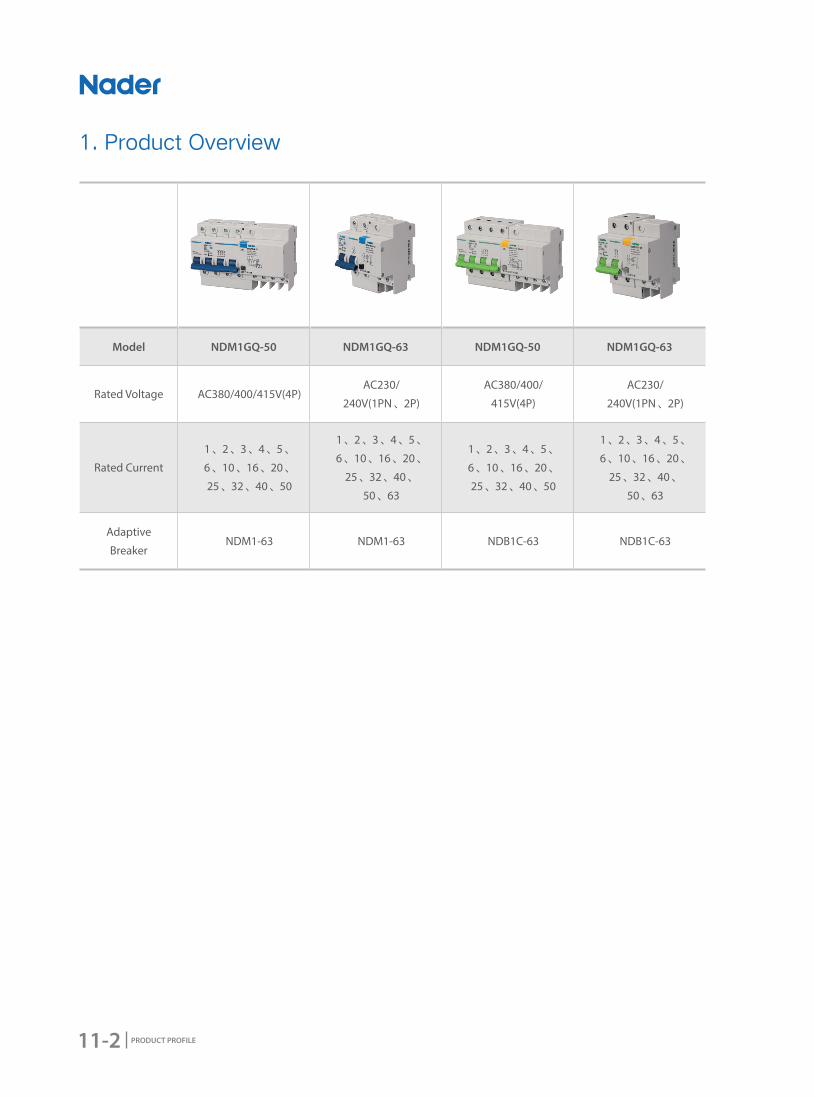
Model NDM1GQ-50 NDM1GQ-63 NDM1GQ-50 NDM1GQ-63
Rated Voltage AC380/400/415V(4P)AC230/
240V(1PN、2P)
AC380/400/
415V(4P)
AC230/
240V(1PN、2P)
Rated Current
1、2、3、4、5、
6、10、16、20、
25、32、40、50
1、2、3、4、5、
6、10、16、20、
25、32、40、
50、63
1、2、3、4、5、
6、10、16、20、
25、32、40、50
1、2、3、4、5、
6、10、16、20、
25、32、40、
50、63
Adaptive
BreakerNDM1-63 NDM1-63 NDB1C-63 NDB1C-63
1. Product Overview
11-3
NDM1GQ Series Under-voltage and Over-voltage Protective Breaker
PRODUCT PROFILE
2. Product Features
● Applicable ScopeNDM1GQ Series Product adopts the assemble structure( between MCCB and under-voltage&over-
voltage protective breaks) to do the protection against over voltage,over current and short circuit. It is
a kind of multi-functional breakers and widely used in Low-voltage distribution of industry,civil building
,energy,telecommunication and infrastructure etc.
● Design Features ◆ Visual window's design: Make the product's switching-closing status more clearly to see.
◆ Modulation Structure:Easily to assemble and diversify
● Structure Features ◆ NDM1GQ External Diagram
● Standard ◆ The Subjected MCB's Complied Standards
★ GB 16917.1Residual current operated circuit-breakers with integral overcurrent protection for
household and similar uses(RCBOs)-Part 1:General rules
★ IEC 61009-1 Residual current operated circuit-breakers with integral overcurrent protection for
household and similar uses(RCBOs)-Part 1:General rules
◆ NDM1L-100 Standards as Follow:
★ GB 14048.2 Low-voltage switchgear and controlgear-Part 2:Circu it-breakers
★ IEC 60947-2 Low-voltage switchgear and controlgear-Part 2:Circuit-breakers
1:Line
2:Test Button
3:Operation Handle
4:Reseting Button
5:Load
1
2
3
4 5
11-4 PRODUCT PROFILE
3. Working Condition
● Applicable Condition ◆ Ambient Usage Temperature and Storage Temperature
Ambient Usage Temperature: -25℃~+55℃, Standard Temperature:+30℃, correction factor of different
ambient usage temperature refer to sheet 1
Storage Temperature: -30℃~+70℃.
◆ Altitude
The altitude of the mounting site≤2000m
◆ Relative Usage Humidity and Relative Storage Humidity
The relative humidity shouldn't exceed 50% when the ambient air temperature is +40 degrees, higher
humidity can be allowed in lower temperature. For example, the humidity can be 90% when the ambient
temperature is +20 degrees. Necessary measures should be acted for the condensation produced by
the changed temperature.
● Pollution Degree2
● Protection LevelLevel of Product Protection:IP20
● Mounting MethodMounted on TH35mm x 7.5 Standard Rail.
● Mounting Direction ◆ Vertical Mounting: The inclination between mounting plane and vertical plane should ≤±5 degrees
◆ Horizontal Mounting
● Environmental RequirementComply with RoHS

11-5
NDM1GQ Series Under-voltage and Over-voltage Protective Breaker
PRODUCT PROFILE
No. Implication Instruction
1 Brand Code ND:
2 Code M
3 Design Code 1
4Over-Voltage and
Under-Voltage
Functional Code
GQ:Indicates over-voltage and under-voltage protective function
G:Indicates over-voltage protective function
Q:Indicates under-voltage protective function
5 Frame Rating 50 63
6Instantaneous
Tripping
Characteristics
B:Instantaneous Tripping
Range: 3In~5In;
C:Instantaneous Tripping
Range: 5In~10In;
D:Instantaneous Tripping
Range: 10In~14In;
B:Instantaneous Tripping
Range: 3In~5In;
C:Instantaneous Tripping
Range: 5In~10In;
D:Instantaneous Tripping
Range: 10In~14In;
7Rated
Current(A)1、2、3、4、5、6、10、16、
20、25、32、40、50、63
1、2、3、4、5、6、10、16、
20、25、32、40、50、63
8 Number of Poles 4P 1PN,2P
4. Product Technical Characteristic
4.1 Model and Implication
ND - /1M
1 2 3 64 7 85
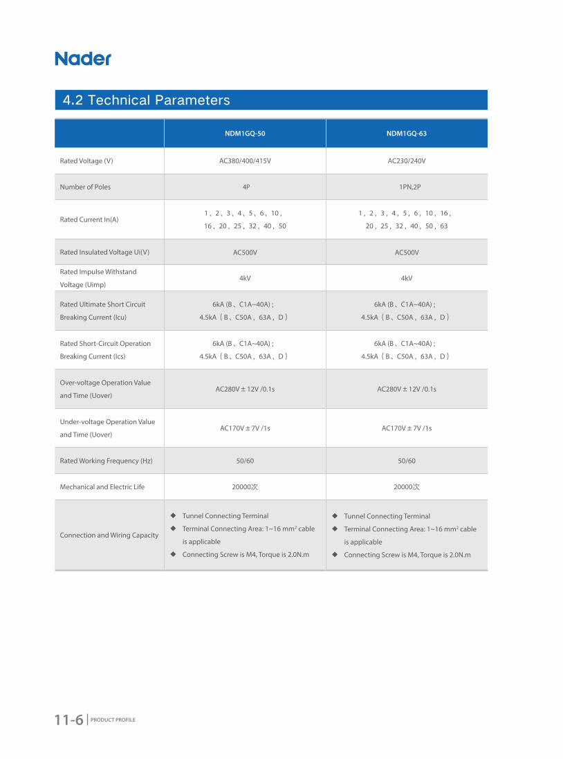
11-6 PRODUCT PROFILE
4.2 Technical Parameters
NDM1GQ-50 NDM1GQ-63
Rated Voltage (V) AC380/400/415V AC230/240V
Number of Poles 4P 1PN,2P
Rated Current In(A)1,2,3,4,5,6,10,
16,20,25,32,40,50
1,2,3,4,5,6,10,16,
20,25,32,40,50,63
Rated Insulated Voltage Ui(V) AC500V AC500V
Rated Impulse Withstand
Voltage (Uimp)4kV 4kV
Rated Ultimate Short Circuit
Breaking Current (Icu)
6kA (B、C1A~40A);
4.5kA(B、C50A,63A,D)
6kA (B、C1A~40A);
4.5kA(B、C50A,63A,D)
Rated Short-Circuit Operation
Breaking Current (Ics)
6kA (B、C1A~40A);
4.5kA(B、C50A,63A,D)
6kA (B、C1A~40A);
4.5kA(B、C50A,63A,D)
Over-voltage Operation Value
and Time (Uover)AC280V±12V /0.1s AC280V±12V /0.1s
Under-voltage Operation Value
and Time (Uover)AC170V±7V /1s AC170V±7V /1s
Rated Working Frequency (Hz) 50/60 50/60
Mechanical and Electric Life 20000次 20000次
Connection and Wiring Capacity
◆ Tunnel Connecting Terminal
◆ Terminal Connecting Area: 1~16 mm2 cable
is applicable
◆ Connecting Screw is M4, Torque is 2.0N.m
◆ Tunnel Connecting Terminal
◆ Terminal Connecting Area: 1~16 mm2 cable
is applicable
◆ Connecting Screw is M4, Torque is 2.0N.m

11-7
NDM1GQ Series Under-voltage and Over-voltage Protective Breaker
PRODUCT PROFILE
-35 -30 -25 -20 -15 -10 -5 -0 5 10 15
1 1.27 1.25 1.23 1.21 1.19 1.17 1.15 1.13 1.10 1.08 1.06
3 3.89 3.83 3.76 3.70 3.64 3.57 3.50 3.44 3.37 3.30 3.22
6 7.70 7.58 7.46 7.34 7.21 7.09 6.96 6.83 6.70 6.56 6.42
10 13.89 13.62 13.35 13.07 12.81 12.53 12.23 11.93 11.63 11.33 11.01
16 20.78 20.43 20.08 19.75 19.40 19.05 18.70 18.33 17.96 17.58 17.20
20 25.67 25.28 24.88 24.47 24.06 23.64 23.22 22.78 22.34 21.89 21.43
25 32.21 31.72 31.22 30.70 30.18 29.65 29.10 28.55 27.98 27.41 26.82
32 41.04 40.46 39.82 39.17 38.51 37.84 37.15 36.47 35.75 35.03 34.30
40 51.63 50.86 50.04 40.21 48.37 47.51 46.63 45.74 44.83 43.90 42.95
50 64.92 63.97 62.92 61.86 60.77 59.67 58.54 57.40 56.23 55.05 53.81
63 83.48 82.06 80.64 79.19 77.72 76.22 74.70 73.14 71.54 69.91 68.24
20 25 30 35 40 45 50 55 60 65 70
1 1.05 1.02 1.00 0.97 0.94 0.91 0.89 0.86 0.83 0.80 0.77
3 3.14 3.06 3.00 2.92 2.84 2.76 2.67 2.58 2.49 2.38 2.27
6 6.27 6.14 6.00 5.84 5.68 5.52 5.36 5.19 5.01 4.83 4.64
10 10.67 10.34 10.00 9.63 9.24 8.85 8.45 8.01 7.55 7.06 6.55
16 16.80 16.40 16.00 15.55 15.11 14.66 14.20 13.71 13.21 12.70 12.75
20 20.96 20.47 20.00 19.47 18.95 18.42 17.87 17.30 16.71 16.10 15.47
25 26.22 25.61 25.00 24.33 23.67 23.00 22.28 21.56 20.80 20.02 19.21
32 33.54 32.77 32.00 31.17 30.34 29.48 28.60 27.69 26.75 25.78 24.77
40 41.98 40.99 40.00 38.93 37.85 36.75 35.61 34.43 33.21 31.95 30.63
50 52.56 51.28 50.00 47.82 46.24 44.81 43.33 41.81 40.23 38.58 35.77
63 66.53 64.78 63.00 60.11 58.19 56.21 54.16 52.03 49.81 47.50 43.05
● Temperature Correction Factor Sheet (1)
Ambient
Temperature(℃)
Correction Current (A)
Rated Current(A)
Ambient
Temperature(℃)
Correction Current (A)
Rated Current(A)
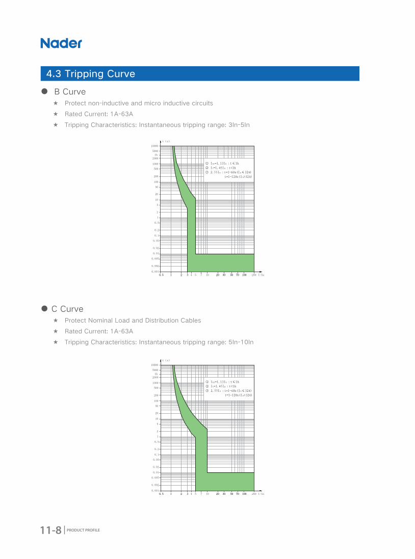
11-8 PRODUCT PROFILE
● B Curve ★ Protect non-inductive and micro inductive circuits
★ Rated Current: 1A-63A
★ Tripping Characteristics: Instantaneous tripping range: 3In-5In
● C Curve ★ Protect Nominal Load and Distribution Cables
★ Rated Current: 1A-63A
★ Tripping Characteristics: Instantaneous tripping range: 5In-10In
4.3 Tripping Curve
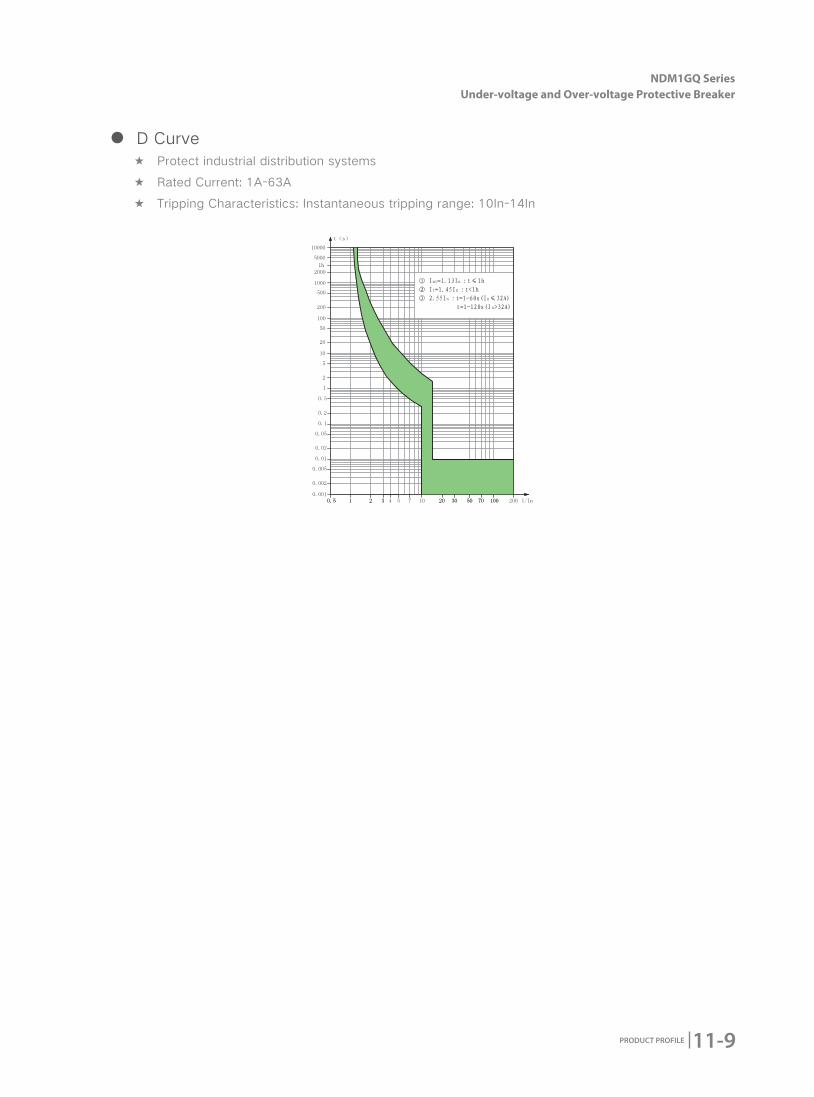
11-9
NDM1GQ Series Under-voltage and Over-voltage Protective Breaker
PRODUCT PROFILE
● D Curve ★ Protect industrial distribution systems
★ Rated Current: 1A-63A
★ Tripping Characteristics: Instantaneous tripping range: 10In-14In

11-10 PRODUCT PROFILE
5. Accessory
5.1 Accessory Sheet
5.2 NDM1GQ-50、63 Accessory Types
No. Name Accessory Code Function and Matched Quantity
1 Auxiliary Contact OFLinked to the left side of MCB to indicate OPEN or CLOSE status of the
associated breaker. Matched quantity :Max 3 Pcs
2 Alarm Contact SDLinked to the left side of MCB to indicate the accidental tripping status of the
associated breaker. Matched quantity:3 Pcs Max.
Auxiliary Contact OF
Alarm Contact SD
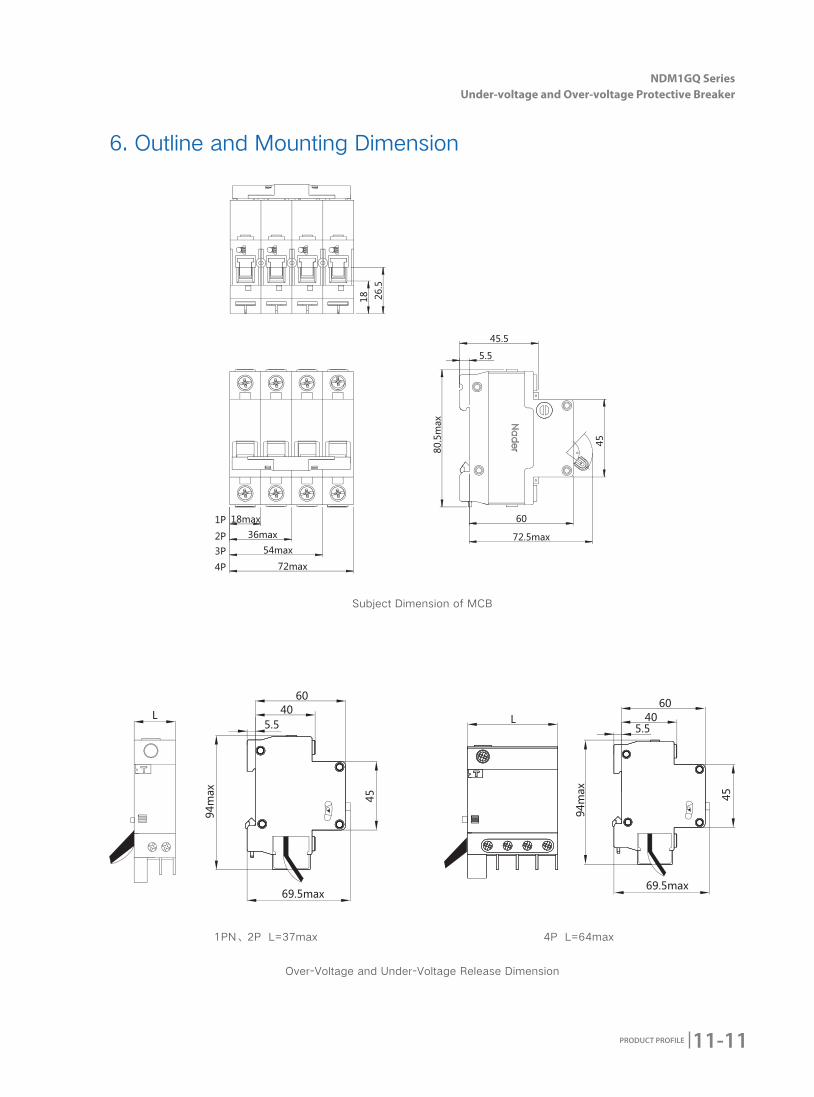
11-11
NDM1GQ Series Under-voltage and Over-voltage Protective Breaker
PRODUCT PROFILE
Subject Dimension of MCB
Over-Voltage and Under-Voltage Release Dimension
1PN、2P L=37max 4P L=64max
6. Outline and Mounting Dimension
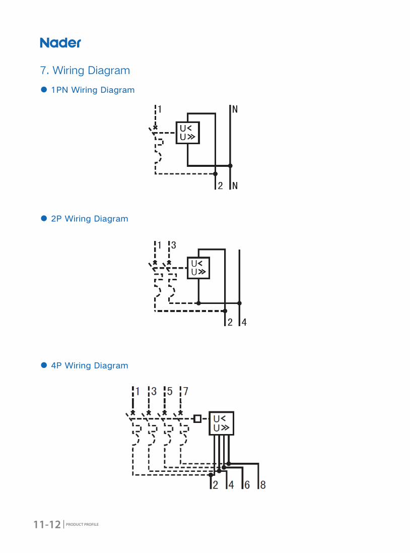
11-12 PRODUCT PROFILE
7. Wiring Diagram
● 1PN Wiring Diagram
● 2P Wiring Diagram
● 4P Wiring Diagram

11-13
NDM1GQ Series Under-voltage and Over-voltage Protective Breaker
PRODUCT PROFILE
Customer Ordering Quantity:
Ordering Date:
Frame Rating □NDM1GQ-50 □NDM1GQ-63
Number of Poles □4P □1PN □2P
Rated Working
Voltage(V) □AC380/400/415 □AC230/240
Rated Working
Current(A)
1、2、3、4、5、6、10、16、20、
25、32、40、50
1、2、3、4、5、6、10、16、20、
25、32、40、50、63
Instantaneous
Tripping
Characteristics
□B:Instantaneous tripping range: 3In-5In, protect non-inductive and micro inductive circuits
□C:Instantaneous tripping range: 5In-10In, protect Nominal Load and Distribution Cables
□D:Instantaneous tripping range: 10In-14In, protect industrial distribution systems
Over-Voltage and
Under-Voltage
Functional Code
□GQ:Indicates over-voltage and under-voltage protective function
□G:Indicates over-voltage protective function
□Q:Indicates under-voltage protective function
Tie Breaker□NDM1-63
□NDB1C-63
8. Ordering Types and Specifications (Tick √ in □)

11-14 PRODUCT PROFILE
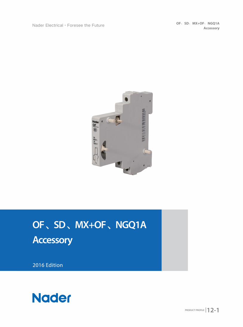
12-1
OF、SD、MX+OF、NGQ1A Accessory
PRODUCT PROFILE
2016 Edition
OF、SD、MX+OF、NGQ1A
Accessory
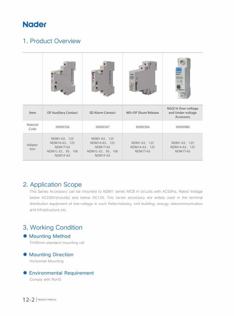
12-2 PRODUCT PROFILE
Item OF Auxiliary Contact SD Alarm Contact MX+OF Shunt ReleaseNGQ1A Over-voltage
and Under-voltage Accessory
Material Code 30000336 30000347 30000364 30000986
Adapta-tion
NDM1-63、125NDM1A-63、125
NDM1T-63NDM1L-32、50、100
NDM1F-63
NDM1-63、125NDM1A-63、125
NDM1T-63NDM1L-32、50、100
NDM1F-63
NDM1-63、125NDM1A-63、125
NDM1T-63
NDM1-63、125NDM1A-63、125
NDM1T-63
1. Product Overview
2. Application Scope This Series Accessory can be mounted to NDM1 series MCB in circuits with AC50Hz, Rated Voltage
below AC230V(include) and below DC125. This series accessory are widely used in the terminal
distribution equipment of low-voltage in such fields:Industry, civil building, energy, telecommunication
and infrastructure etc.
3. Working Condition ● Mounting Method
TH35mm standard mounting rail
● Mounting DirectionHorizontal Mounting
● Environmental RequirementComply with RoHS
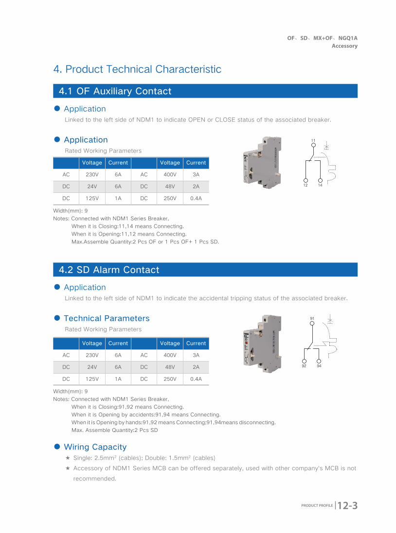
12-3
OF、SD、MX+OF、NGQ1A Accessory
PRODUCT PROFILE
4. Product Technical Characteristic
4.1 OF Auxiliary Contact
4.2 SD Alarm Contact
● ApplicationLinked to the left side of NDM1 to indicate OPEN or CLOSE status of the associated breaker.
● ApplicationRated Working Parameters
● ApplicationLinked to the left side of NDM1 to indicate the accidental tripping status of the associated breaker.
● Technical ParametersRated Working Parameters
● Wiring Capacity ★ Single: 2.5mm2 (cables); Double: 1.5mm2 (cables)
★ Accessory of NDM1 Series MCB can be offered separately, used with other company's MCB is not
recommended.
Voltage Current Voltage Current
AC 230V 6A AC 400V 3A
DC 24V 6A DC 48V 2A
DC 125V 1A DC 250V 0.4A
Voltage Current Voltage Current
AC 230V 6A AC 400V 3A
DC 24V 6A DC 48V 2A
DC 125V 1A DC 250V 0.4A
Width(mm): 9
Notes: Connected with NDM1 Series Breaker,
When it is Closing:11,14 means Connecting.
When it is Opening:11,12 means Connecting.
Max.Assemble Quantity:2 Pcs OF or 1 Pcs OF+ 1 Pcs SD.
Width(mm): 9
Notes: Connected with NDM1 Series Breaker,
When it is Closing:91,92 means Connecting.
When it is Opening by accidents:91,94 means Connecting.
When it is Opening by hands:91,92 means Connecting;91,94means disconnecting.
Max. Assemble Quantity:2 Pcs SD

12-4 PRODUCT PROFILE
● ApplicationLinked to the left side of NDM1 to indicate the accidental
tripping status of the associated breaker.
● Technical ParametersControlled Voltage: AC 230V/400V DC 24V/48V
Width(mm): 18
Note: The conversion contact should be active contact and the
former can't be passive contact to connect the other ELV module.
4.3 MX+OF Shunt Release
4.4 NGQ1A Over-voltage and Under-voltage Release
Note: When the voltage of control power circuit is DC24v, we recommend you to take the shunt control loop design as above.
ZJ: Represent the middle relay(the contact capacity should be 1A)
● Wiring Capacity ★ Single: 2.5mm2 (cables); Double: 1.5mm2(cables)
★ This accessory can be offered separately, used with other company's MCB is not recommended.
● ApplicationLinked to the right side of NDM1-63 to realize the protection
function of single-phase over-voltage, under-voltage, over-
voltage and under-voltage.
● Technical Parameters ★ Rated Over-voltage operation value (Uover):AC280V±5%,
Max. Breaking Time: 0.2S
★ Rated Under-voltage operation value (Uunder)Uunder:AC170V±7%,
Max. Breaking Time: 1S
★ Width(mm): 18
Note: User can select over-voltage release or under-voltage release depend on their need.
Every circuit breaker only matched with 1Pcs over-voltage release to realize the single path protection.
Power Line
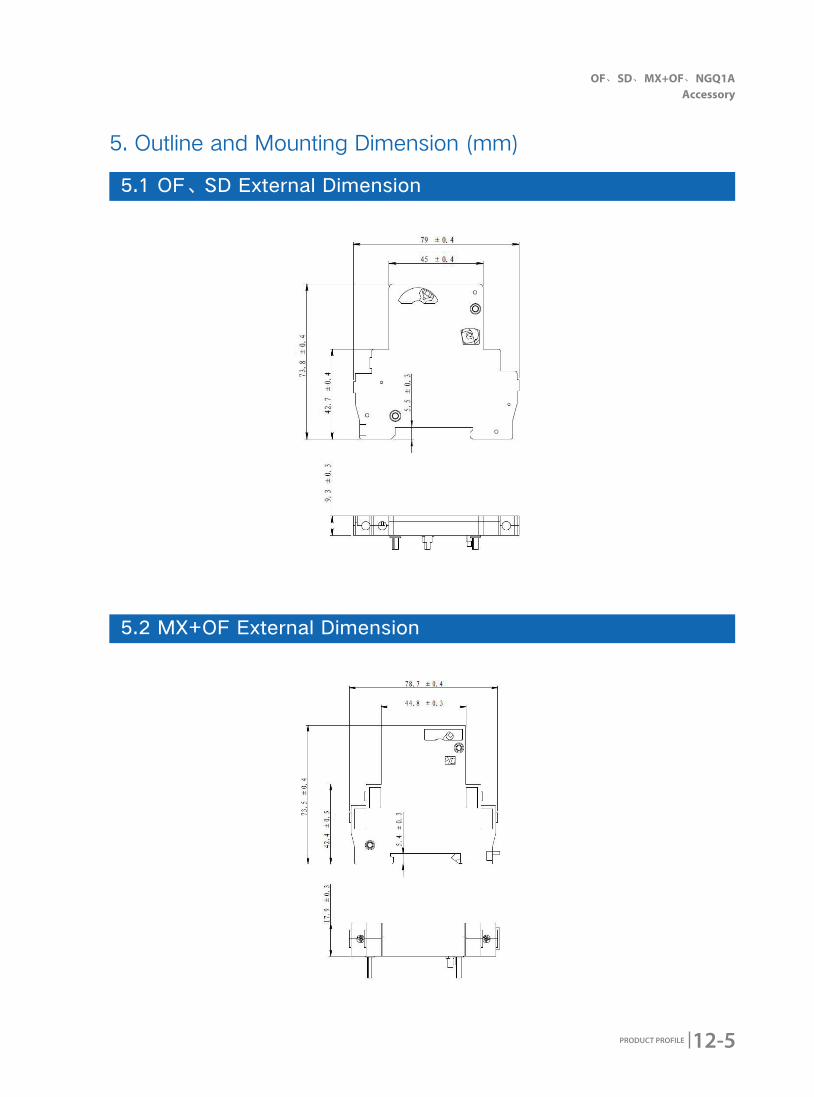
12-5
OF、SD、MX+OF、NGQ1A Accessory
PRODUCT PROFILE
5. Outline and Mounting Dimension (mm)
5.1 OF、SD External Dimension
5.2 MX+OF External Dimension
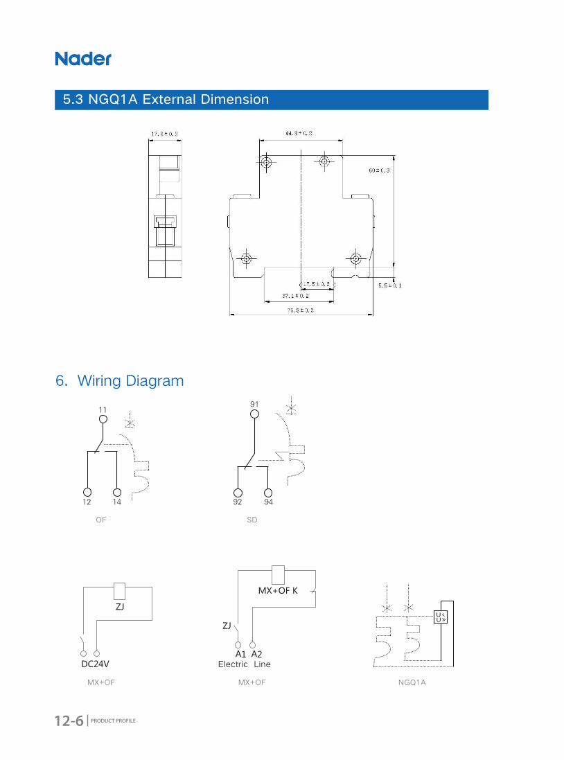
12-6 PRODUCT PROFILE
6. Wiring Diagram
5.3 NGQ1A External Dimension
OF
MX+OF
SD
MX+OF NGQ1A
Electric Line
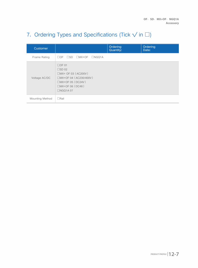
12-7
OF、SD、MX+OF、NGQ1A Accessory
PRODUCT PROFILE
Customer Ordering Quantity:
Ordering Date:
Frame Rating □OF □SD □MX+OF □NGQ1A
Voltage AC/DC
□OF 01
□SD 02
□MX+ OF 03(AC200V)
□MX+OF 04(AC230/400V)
□MX+OF 05(DC24V)
□MX+OF 06(DC48)
□NGQ1A 07
Mounting Method □Rail
7. Ordering Types and Specifications (Tick √ in □)