Embed Size (px)
Citation preview

User GuideNCR XL15 (5915)
Release 1.0
BCC5–0000–5162Issue C

The product described in this document is a licensed product of NCR Corporation.
NCR is a registered trademark of NCR Corporation. NCR RealPOS is a trademark of NCR Corporation inthe United States and/or other countries. Other product names mentioned in this publication may betrademarks or registered trademarks of their respective companies and are hereby acknowledged.
The terms HDMI and HDMI High-Definition Multimedia Interface, and the HDMI Logo are trademarksor registered trademarks of HDMI Licensing LLC in the United States and other countries.
Where creation of derivative works, modifications or copies of this NCR copyrighted documentation ispermitted under the terms and conditions of an agreement you have with NCR, NCR's copyright noticemust be included.
It is the policy of NCR Corporation (NCR) to improve products as new technology, components,software, and firmware become available. NCR, therefore, reserves the right to change specificationswithout prior notice.
All features, functions, and operations described herein may not be marketed by NCR in all parts of theworld. In some instances, photographs are of equipment prototypes. Therefore, before using thisdocument, consult with your NCR representative or NCR office for information that is applicable andcurrent.
To maintain the quality of our publications, we need your comments on the accuracy, clarity,organization, and value of this book. Please use the link below to send your comments.
EMail: [email protected]
Copyright © 2017By NCR CorporationDuluth, GA U.S.A.All Rights Reserved

i
Preface
AudienceThis book is written for hardware installer/service personnel, system integrators, andfield engineers.
Notice: This document is NCR proprietary information and is not to be disclosed orreproduced without consent.
Safety RequirementsThe NCR XL15 conforms to all applicable legal requirements. To view the compliancestatements see the NCR RealPOS Terminals Safety and Regulatory Statements (B005-0000-1589).
Caution: The on/off switch is a logic switch only. The AC line voltage primaries are liveat all times when the power cord is connected. Therefore, disconnect the AC powercord before opening the unit to install features or service this terminal.
Lithium Battery WarningWarning: Danger of explosion if battery is incorrectly replaced. Replace only withthe same or equivalent type as recommended by the manufacturer. Discard usedbatteries according to the manufacturer's instructions.
Attention: Il y a danger d'explosion s'il y a remplacement incorrect de la batterie.Remplacer uniquement avec une batterie du même type ou d'un type recommandépar le constructeur. Mettre au rébut les batteries usagées conformément auxinstructions du fabricant.
Battery Disposal (Switzerland)Refer to Annex 4.10 of SR814.013 for battery disposal.
IT Power SystemThis product is suitable for connection to an IT power system with a phase-to-phasevoltage not exceeding 240 V.
Peripheral UsageThis terminal should only be used with peripheral devices that are certified by theappropriate safety agency for the country of installation (UL, CSA, TUV, VDE) or thosewhich are recommended by NCR Corporation.
Warning: DO NOT connect or disconnect the transaction printer while the terminalis connected to AC power. This can result in system or printer damage.

ii
Warning: DO NOT connect or disconnect any serial peripherals while the terminalis connected to AC power. This can result in system or printer damage.
Grounding InstructionsIn the event of a malfunction or breakdown, grounding provides a path of leastresistance for electric current to reduce the risk of electric shock. This product isequipped with an electric cord having an equipment-grounding conductor and agrounding plug. The plug must be plugged into a matching outlet that is properlyinstalled and grounded in accordance with all local codes and ordinances. Do notmodify the plug provided – if it will not fit the outlet, have the proper outlet installed bya qualified electrician. Improper connection of the equipment-grounding conductor canresult in a risk of electric shock.
The conductor with insulation having an outer surface that is green with or withoutyellow stripes is the equipment-grounding conductor.
If repair or replacement of the electric cord or plug is necessary, do not connect theequipment-grounding conductor to a live terminal. Check with a qualified electrician orservice personnel if the grounding instructions are not completely understood, or if youare in doubt as to whether the product is properly grounded.
Use only 3-wire extension cords that have 3-prong grounding plugs and 3-polereceptacles that accept the product’s plug. Repair or replace damaged or worn cordsimmediately.

iii
Out of Box Failure (OBF)If you experience an out of box failure (OBF) during installation or staging related to amissing, wrong or defective unit or item, simply provide NCR with a detaileddescription of the issue and the item will be replaced free of charge. For assistance withthis process send an email to [email protected] the following details:
• NCR Sales Order # (Sales Order # are located on the box)
• Date of Product Installation
• Product Model #
• Unit Serial #
• NCR part # of defective/missing/wrong component
• Description of Failure (please be specific. For example: “display will not power on”)
• Customer/Requestor’s contact name, phone number and/or e-mail address
• Address to ship replacement part(s)
Transport the product n its original packaging to prevent impact damages.
If you do not have access to a computer, you may leave a voice message at: 1-800-528-8658 (USA), or (International) +1-770-623-7400. When leaving a message, please provide aphone number and/or an email address so NCR can contact you if additional details areneeded.
Note: Used equipment that experiences a failure does not qualify as an OBF and shouldgo through the NCR warranty process.
WarrantyWarranty terms vary by region and country.
All parts of this product that are subject to normal wear and tear are not included in thewarranty. In general, damages due to the following are not covered by the warranty.
• Improper or insufficient maintenance
• Improper use or unauthorized modifications of the product.
• Inadequate location or surroundings. Site installation must conform to guidelineslisted in the Site Preparation section of this document and the NCR Workstation andPeripheral AC Wiring Guide (BST0-2115-53).
For detailed warranty arrangements please consult your contract documents.

iv
Returning Defective Hardware for ServiceUse the following procedure to report/return defective hardware.
Call the NCR Customer Care Center at 1-800-262-7782 and have the following informationavailable when you place the call.
• Class/Model number of the defective equipment
• Serial Number of the defective equipment
• Equipment location in the store
• Description of the problem, including any system error codes, error condition, orguidance to the area of failure.
The NCR Agent will provide you with a work order number, which serves as yourReturn Material Authorization (RMA). Please provide the RMA on the outside of theshipping box.
Note: A work order must be opened for each device that is shipped for repair.

v
Table of Contents
Chapter 1: Product OverviewBase Models 1Features and Benefits 2Optional Features 3
Specifications 8Display Mounts 10
XL–Series Stand (5915–F033, 5915–K033) 10Integration Tray Mount (5968–K024) 10Checkstand Mount (5968–K039) 11Wall Mount (7702–K320) 11Third Party Mounts 12Customer Display (7702–K453) 13
Front Panel Power LED 14Label Locations 15
Chapter 2: Hardware InstallationInstallation Restrictions 16Ergonomic Workplace 17Installing the Display 18XL-Series Stand 19Connecting to a POS Terminal 24Display Port Cables 24External Power Cables 25Powered USB Cables 26Audio Cable 26Adapters 27
Chapter 3: Operation and CleaningTouchscreens 31Projected Capacitive Touchscreen 31Using the PCap Touchscreen 31
Resistive Touchscreen 32Using the Resistive Touchscreen 32

vi
Touchscreen Cleaning Procedures 32Magnetic Stripe Reader 33Using the MSR 33Care of Cards 33Card Thickness 33
Cabinet Cleaning Procedures 34
Chapter 4: NCR Software OSD UtilityIntroduction 35Supported Features 35
Installing the Utility 36Running the Utility (GUI Version) 37Main Menu 37Control Buttons 37
Display Adjustment Procedures 40Resetting Factory Defaults 41
Running the Utility (Console Version) 42
Chapter 5: Touchscreen CalibrationProper Touchscreen Methods 43Calibrating the Touchscreen 44Resistive Touchscreen Calibration 44
vii
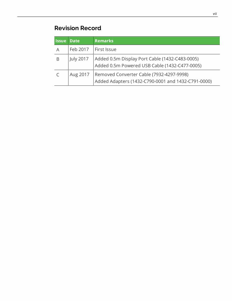
Revision Record
Issue Date Remarks
A Feb 2017 First Issue
B July 2017 Added 0.5m Display Port Cable (1432-C483-0005)Added 0.5m Powered USB Cable (1432-C477-0005)
C Aug 2017 Removed Converter Cable (7932-4297-9998)Added Adapters (1432-C790-0001 and 1432-C791-0000)

Chapter 1: Product Overview
The XL15 display offers flexibility and ultra–thin design that will look great in any retailenvironment. The XL15 display features bright, high contrast LCD to make it easy toread. This stylish display is available as a 15–inch, projected capacitive (PCAP) orresistive touchscreen, or LED backlight non–touch.
The XL15 display is compatible with any product that has a display port video and aUSB interface and can be used as an associate display or rear mounted to a terminal orfree standing to display pricing and promotional messages. This is available with anencrypted magnetic stripe reader (MSR) for enhanced security. Whichever option ispreferred, these displays are sure to enhance the appearance of the wrap stand orcheckout and save valuable counter space.
Base Models
Base Model Description
5915-1015-9090 XL15, 15" Display, No Touch
5915-1115-9090 XL15, 15" Display, Resistive
5915-1315-9090 XL15, 15" Display, PCAP

1-2 Product Overview
Features and Benefits
Features Description
Touch Displays 15" Resistive • Single Touch Interface• Standard 4:3 Aspect Ratio• 1024x768 XGA resolution• 350 NIT LED–Backlit LCD• Narrow Bezel Design• Display Port• Software OSD Support
15" Projected Capacitive (PCap) • Zero Bezel – Alll Glass Front• 10–Point Multi–Touch Interface• Standard 4:3 Aspect Ratio• 1024x768, XGA Resolution• 350 NIT LED–Backlit LCD• Display Port• Software OSD Support
Non–Touch Displays 15" LED Backlight • Zero Bezel – All Glass Front• 350 NIT LED LCD• Standard 4:3 Aspect Ratio• 1024x768, XGA Resolution• Display Port• Software OSD Support
Peripherals MSR, NCR Encrypted USB 3-Track
Provides a 3-Track, Encrypting MSR.
Filler Plate, Right Side Provides a blank plate when an MSR isnot installed.
Filler Plate, Left Side Provides a blank plate when a Port Bfeature is not installed.
Product Overview 1-3
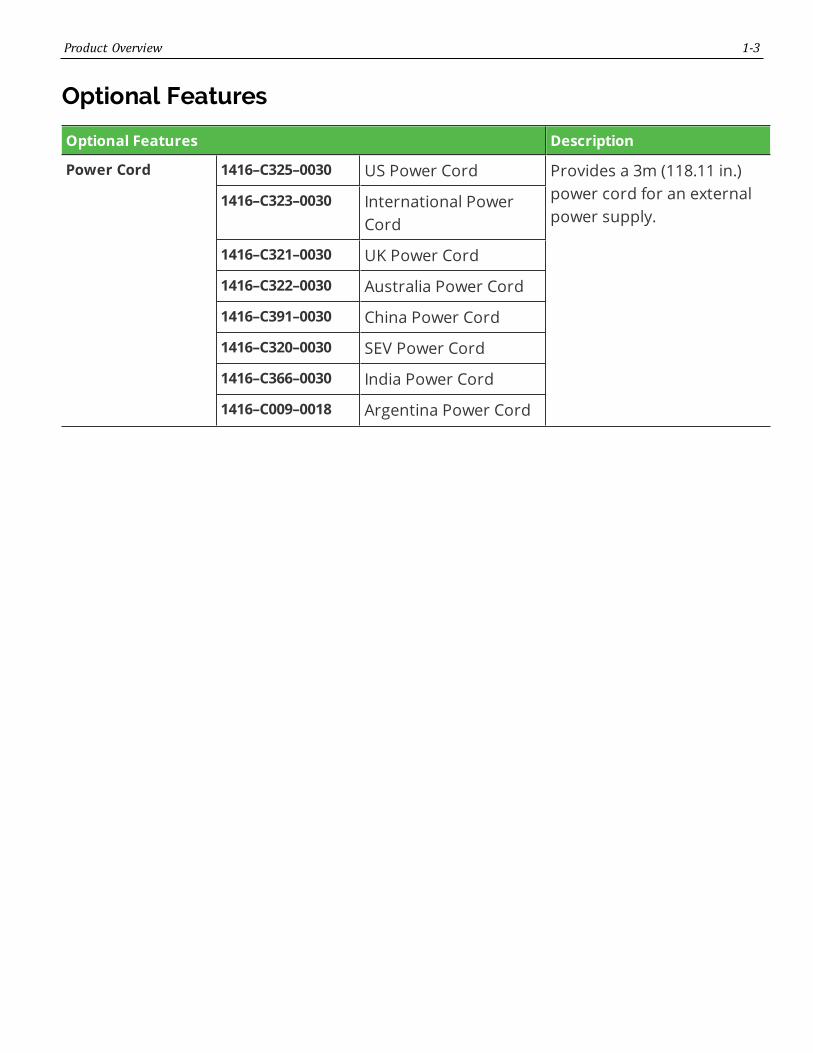
Optional Features
Optional Features Description
Power Cord 1416–C325–0030 US Power Cord Provides a 3m (118.11 in.)power cord for an externalpower supply.
1416–C323–0030 International PowerCord
1416–C321–0030 UK Power Cord
1416–C322–0030 Australia Power Cord
1416–C391–0030 China Power Cord
1416–C320–0030 SEV Power Cord
1416–C366–0030 India Power Cord
1416–C009–0018 Argentina Power Cord
1-4 Product Overview
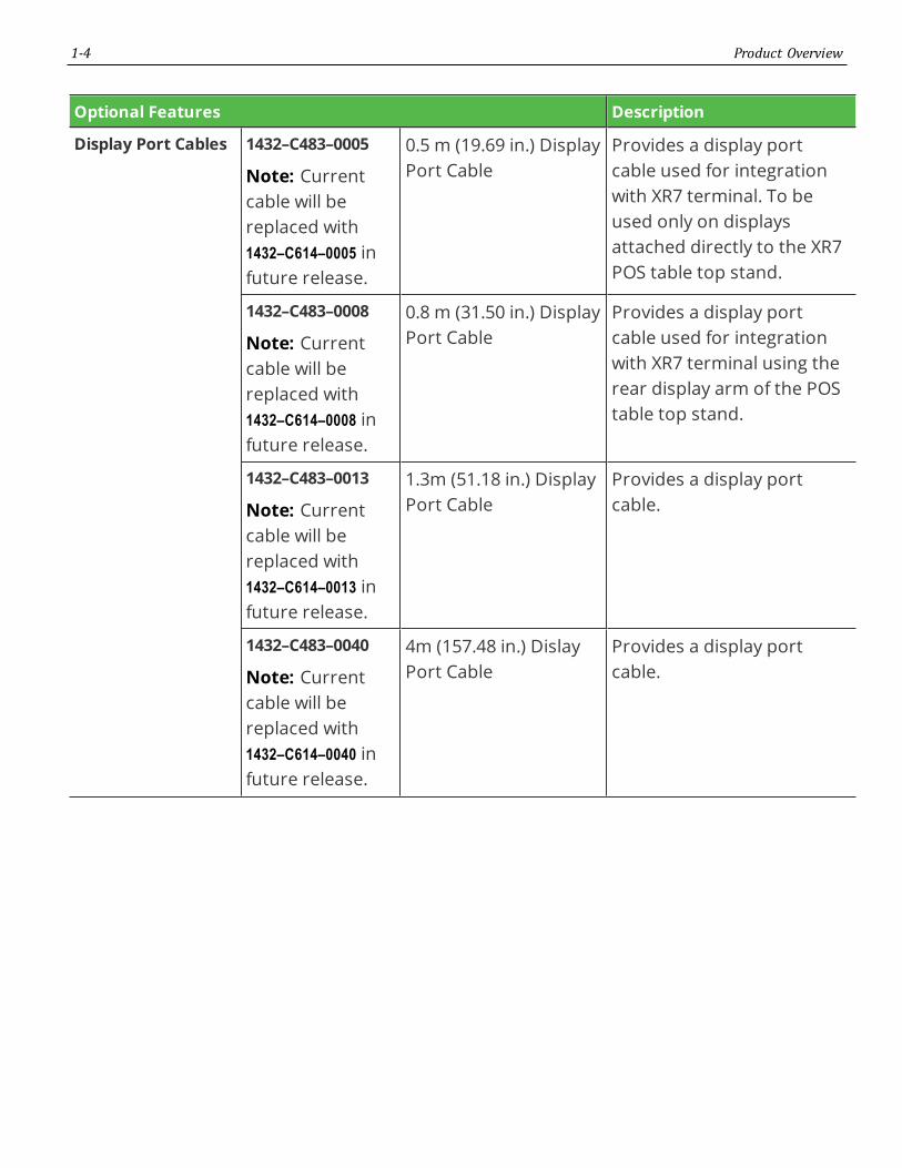
Optional Features Description
Display Port Cables 1432–C483–0005
Note: Currentcable will bereplaced with1432–C614–0005 infuture release.
0.5 m (19.69 in.) DisplayPort Cable
Provides a display portcable used for integrationwith XR7 terminal. To beused only on displaysattached directly to the XR7POS table top stand.
1432–C483–0008
Note: Currentcable will bereplaced with1432–C614–0008 infuture release.
0.8 m (31.50 in.) DisplayPort Cable
Provides a display portcable used for integrationwith XR7 terminal using therear display arm of the POStable top stand.
1432–C483–0013
Note: Currentcable will bereplaced with1432–C614–0013 infuture release.
1.3m (51.18 in.) DisplayPort Cable
Provides a display portcable.
1432–C483–0040
Note: Currentcable will bereplaced with1432–C614–0040 infuture release.
4m (157.48 in.) DislayPort Cable
Provides a display portcable.

Product Overview 1-5
Optional Features Description
External PowerCables
5915–F120 Universal SwitchingMEPS Power Supply -12V, 2.5 A output forTouch (ROHS)
Provides a 12VDC PowerAdapter, 40W, DOE VI, 4 pinMini-DIN connector.
1432–C480–0013
Note: Currentcable will bereplaced with1432–C591–0013 infuture release.
1.3m USB Type A withpower connector
Provides a 1.3m (51.18 in.)USB cable with latching 1x8connector on the displayend, a USB connector on theterminal end, and a barrelconnector in the middle foran external power supply.Requires both an externalpower brick and a localpower cord.
1432–C479–0040
Note: Currentcable will bereplaced with1432–C591–0040 infuture release.
4m USB Type A withpower connector
Provides a 4m (157.48 in.)USB cable with latching 1x8connector on the displayend, a USB connector on theterminal end, and a barrelconnector in the middle foran external power supply.Requires both an externalpower brick and a localpower cord.

1-6 Product Overview
Optional Features Description
Powered USBCables
1432–C477–0005 0.5m 12V Powered USB Provides a 0.5m (19.68 in.)12V USB power cable withlatching 1x8 connector onthe display end and alatching 12V USB + Powerconnector on the terminalend. Provides both powerand touch communication.
1432–C477–0008 0.8m 12V Powered USB Provides a 0.8m (31.50 in.)12V USB power cable withlatching 1x8 connector onthe display end and alatching 12V USB + Powerconnector on the terminalend. Provides both powerand touch communication.
1432–C477–0013 1.3m 12V Powered USB Provides a 1.3m (51.18 in.)12V USB power cable withlatching 1x8 connector onthe display end and alatching 12V USB + Powerconnector on the terminalend. Provides both powerand touch communication.
1432–C478–0040 4m 12V Powered USB Provides a 4m (157.48 in.)12V USB power cable withlatching 1x8 connector onthe display end and a latch-ing 12V USB + Power con-nector on the terminal end.Provides both power andtouch communication.

Product Overview 1-7
Optional Features Description
Audio Cable 1432–C593–0013 1.3m with 3.5mm plugMale
Provides a 1.3m (51.18 in.)black cable for use on ter-minals with a line–out oraudio port.
1432–C593–0040 4m with 3.5mm plugMale
Provides a 4m (157.48 in.)black cable for use on ter-minals with a line–out oraudio port.
MiscellaneousAdapters
1432–C790–0001 Cable, HDMI (Terminal)to DisplayPort (Display)active adapter
Allows connection of adisplay with DisplayPort to aterminal with an HDMIconnection. Must also orderthe DisplayPort cable.Powered by a USB port onterminal.
1432–C791–0000 Adapter, passive, DVI-Dto HDMI
Allows connection of adisplay with DisplayPort to aterminal with an DVIconnection. Must also orderthe DisplayPort cable andthe 1432-C790-0001 adapter.
1-8 Product Overview
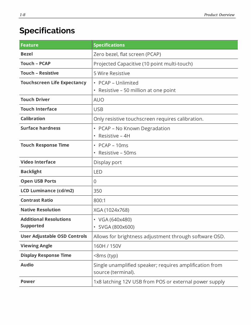
Specifications
Feature Specifications
Bezel Zero bezel, flat screen (PCAP)
Touch – PCAP Projected Capacitive (10 point multi-touch)
Touch – Resistive 5 Wire Resistive
Touchscreen Life Expectancy • PCAP – Unlimited• Resistive – 50 million at one point
Touch Driver AUO
Touch Interface USB
Calibration Only resistive touchscreen requires calibration.
Surface hardness • PCAP – No Known Degradation• Resistive – 4H
Touch Response Time • PCAP – 10ms• Resistive – 50ms
Video Interface Display port
Backlight LED
Open USB Ports 0
LCD Luminance (cd/m2) 350
Contrast Ratio 800:1
Native Resolution XGA (1024x768)
Additional ResolutionsSupported
• VGA (640x480)• SVGA (800x600)
User Adjustable OSD Controls Allows for brightness adjustment through software OSD.
Viewing Angle 160H / 150V
Display Response Time <8ms (typ)
Audio Single unamplified speaker; requires amplification fromsource (terminal).
Power 1x8 latching 12V USB from POS or external power supply

Product Overview 1-9
Feature Specifications
Power consumption • 7.5w (Typical)• 3.3w (Standby)
External USB Connectivity None
MSR Option NCR Encrypted 3-Track
Biometrics None
Camera None
Physical Mounting Interface VESA 75 mm & NCR 100 mm
Color Black
LED Life
(hours to ½ brightness ofbacklight)
50,000 hours
Retail Hardened Moisture/Dust Sealed display, Software OSD, Latching Cables
Certifications TUV/UL/CU/NOM/KC/CCC
Display Area 304.128(H) x 228.096(V)
Operating Temperature 5° to 40°C
Operating Humidity 10% to 90%
Dimensions
(no stand/ no MSR) (w x d x h)
380mm (14.96”) x 44mm (1.73”) x 304mm (11.97”)
Weight 3.4kg (7.5 lbs)

1-10 Product Overview
Display Mounts
XL–Series Stand (5915–F033, 5915–K033)
Integration Tray Mount (5968–K024)

Product Overview 1-11
Checkstand Mount (5968–K039)
Wall Mount (7702–K320)

1-12 Product Overview
Third Party Mounts
VESA Adapter (5915–K320)
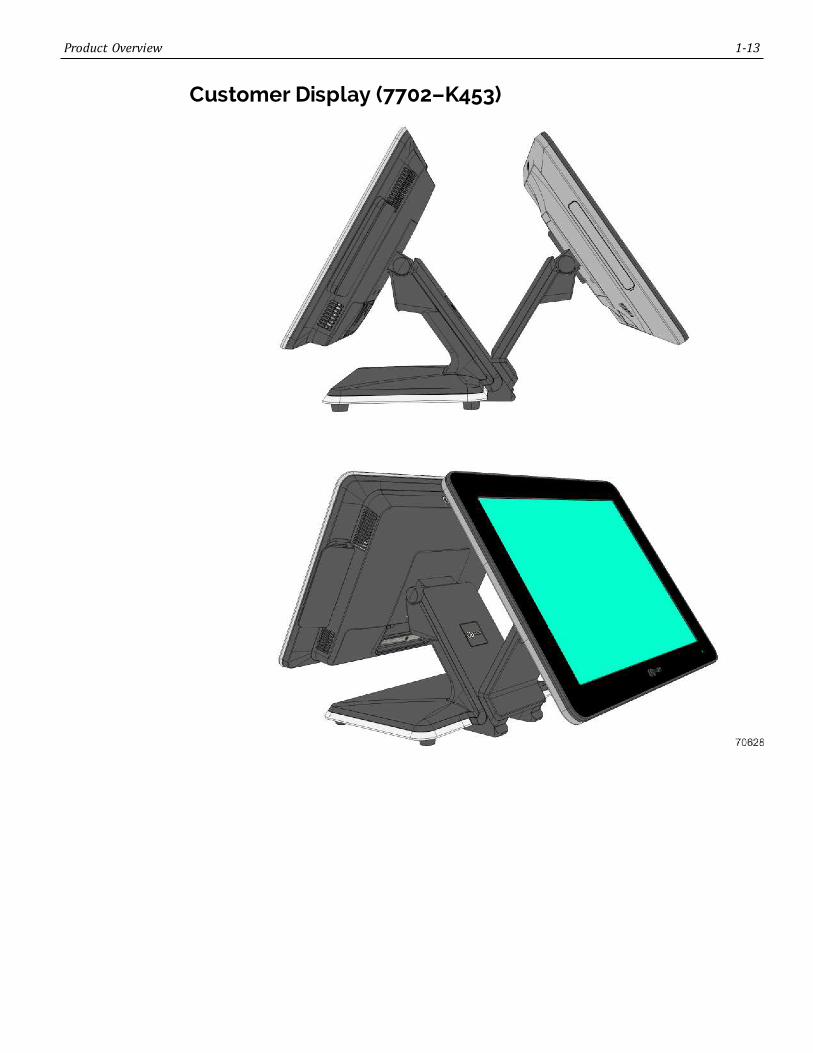
Product Overview 1-13
Customer Display (7702–K453)

1-14 Product Overview
Front Panel Power LED
Color Description
Off System OFF or No Power, NoVideo Signal
Green System ON
Red System Sleep

Product Overview 1-15
Label Locations

Chapter 2: Hardware Installation
Installation RestrictionsBefore installing the NCR XL15 (5915) Display, read and follow the guidelines in theXL15 POS Site Preparation Guide and the NCR Workstation and Peripheral ACWiringGuide (BST0-2115-53).
• Install the display near an electrical outlet that is easily accessible. Use the powercord as a power disconnect device.
• Do not permit any object to rest on the power cord. Do not locate the display wherethe power cord can be walked on.
• Use a grounding strap or touch a grounded metal object to discharge any staticelectricity from your body before servicing the display.
Warning: This unit contains hazardous voltages and should only be serviced byqualified service personnel.
Caution: This device should only be powered by a power supply source whichmeets Safety Extra Low Voltage (SELV) and LPS (Limited Power Source)requirements per UL1950, IEC 950, and EN 60 950. The power source must becertified by the appropriate safety agency for the country of installation.
Caution: Use a grounding strap when installing this feature.
2-17 Hardware Installation
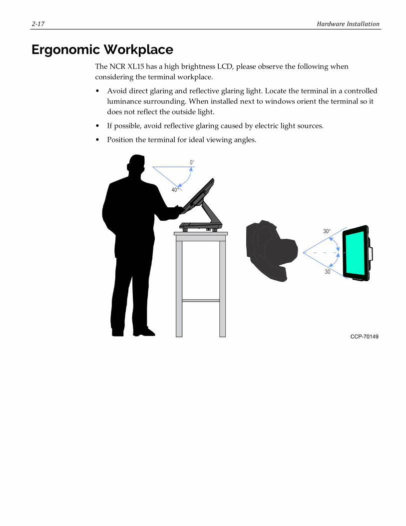
Ergonomic WorkplaceThe NCR XL15 has a high brightness LCD, please observe the following whenconsidering the terminal workplace.
• Avoid direct glaring and reflective glaring light. Locate the terminal in a controlledluminance surrounding. When installed next to windows orient the terminal so itdoes not reflect the outside light.
• If possible, avoid reflective glaring caused by electric light sources.
• Position the terminal for ideal viewing angles.

Hardware Installation 2-18
Installing the DisplayThe XL15 Display can be mounted using a variety of mounts:
• XL–Series Stand (5915–K033)
• Wall Mount (7702–K320)
• Integration Tray Mount (5968–K024)
• Checkstand Mount (5968–K039)
• Third–Party VESA Mounts
This chapter explains how to perform an "Out–of–box" installation of the 5915 displaymounted on the XL–Series Stand and how to connect cables to a POS terminal. Forinstallation procedures for the other mounting options see their associated kitinstructions.
2-19 Hardware Installation
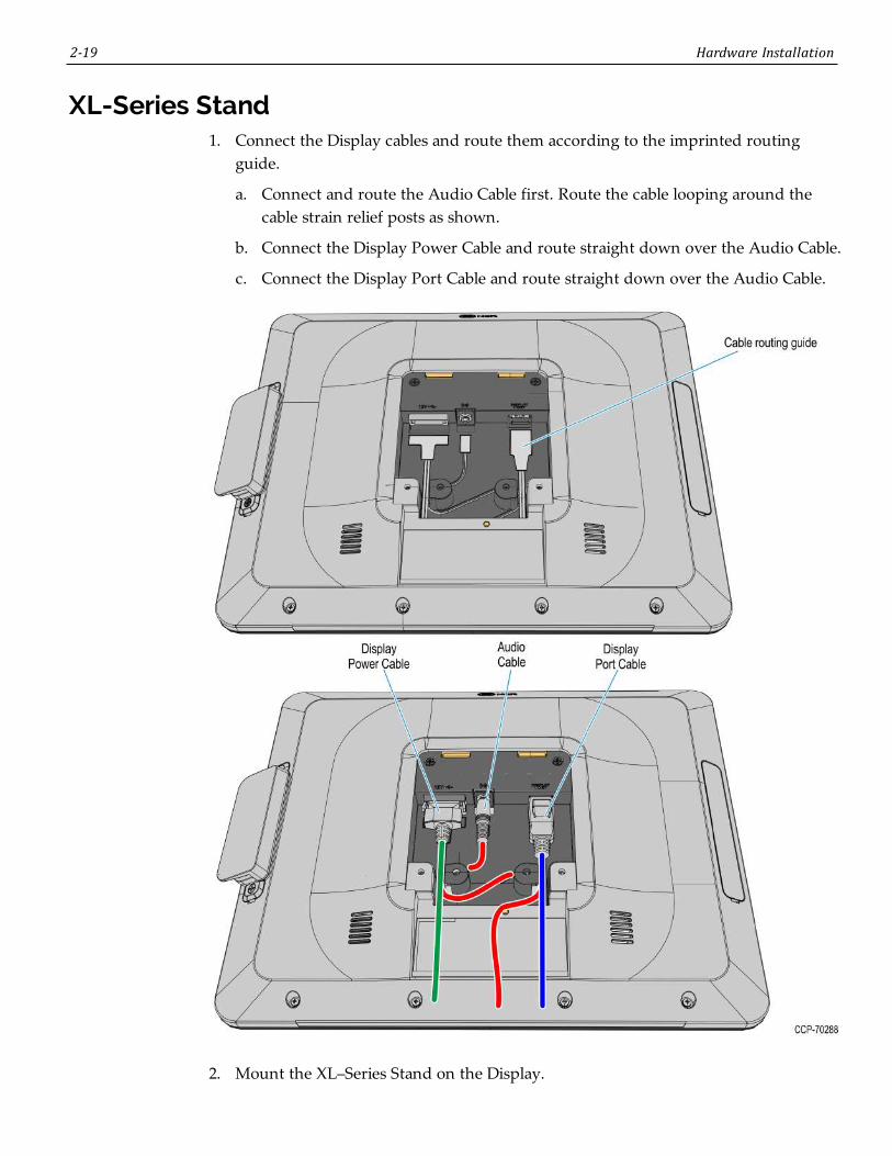
XL-Series Stand1. Connect the Display cables and route them according to the imprinted routing
guide.
a. Connect and route the Audio Cable first. Route the cable looping around thecable strain relief posts as shown.
b. Connect the Display Power Cable and route straight down over the Audio Cable.
c. Connect the Display Port Cable and route straight down over the Audio Cable.
2. Mount the XL–Series Stand on the Display.

Hardware Installation 2-20
a. Insert the VESA tabs into the slots in the rear of the Display and then slowlyrotate the stand assembly downward.
b. Rotate the Stand to the orientation shown below.
2-21 Hardware Installation
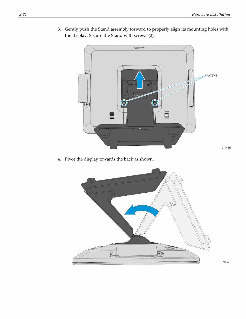
3. Gently push the Stand assembly forward to properly align its mounting holes withthe display. Secure the Stand with screws (2).
4. Pivot the display towards the back as shown.

Hardware Installation 2-22
5. Route and secure the Display cables to the Mounting Bracket then through theStand and then out the base opening.
a. Route the Audio Cable first to the left slot and make sure it is behind the tab inthe slot.
b. Route the Display Port Cable to the left slot and make sure it is behind the tab inthe slot.
c. Route the USB Cable to the right slot and make sure it is behind the tab in theslot.
2-23 Hardware Installation
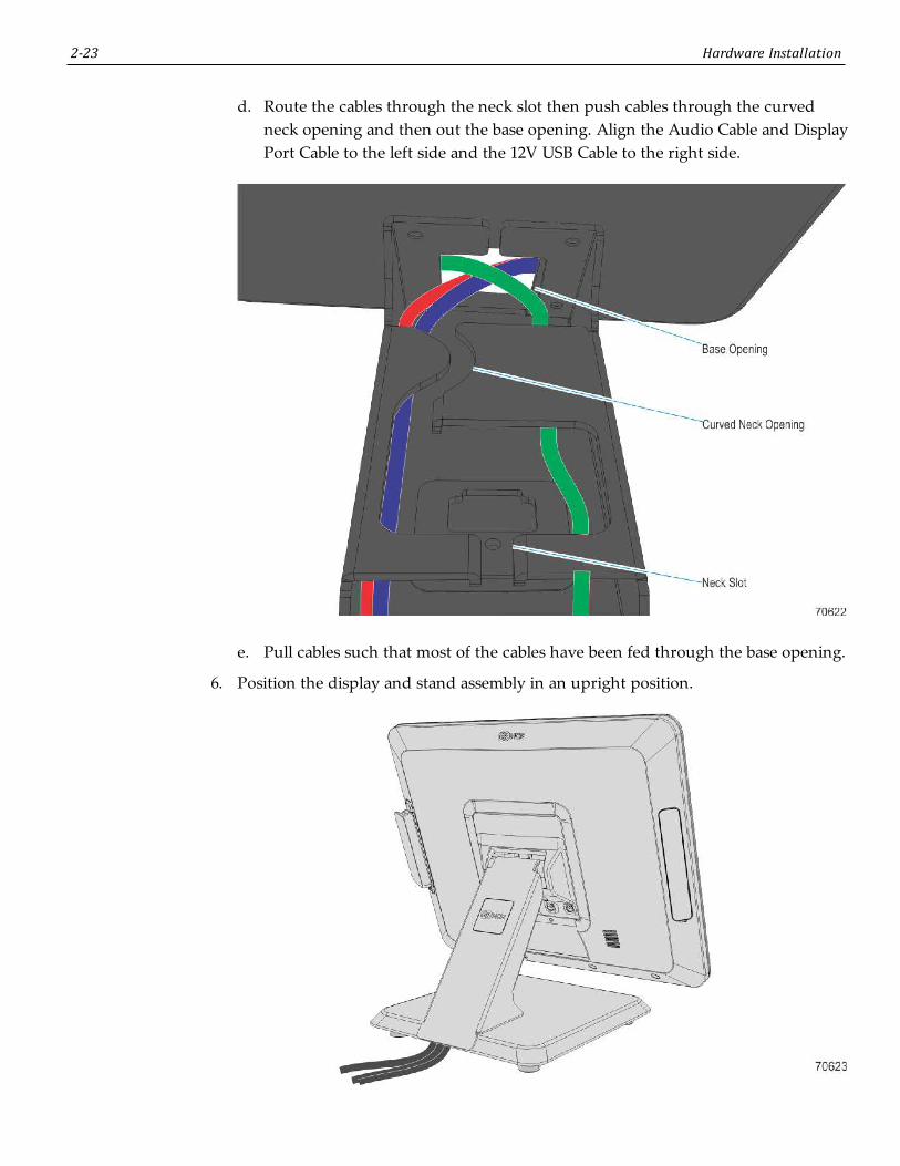
d. Route the cables through the neck slot then push cables through the curvedneck opening and then out the base opening. Align the Audio Cable and DisplayPort Cable to the left side and the 12V USB Cable to the right side.
e. Pull cables such that most of the cables have been fed through the base opening.
6. Position the display and stand assembly in an upright position.

Hardware Installation 2-24
Connecting to a POS TerminalThe following illustrations show the host terminal cable connections. The requiredcables vary depending on the available video connectors on the host terminal.
Display Port CablesThe Display Port Cable provides video to the display.
• Connect the Display Port Cable to the Display Port connectors on both the displayand the terminal.

2-25 Hardware Installation
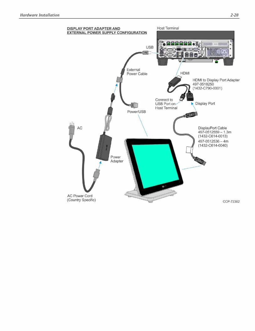
External Power CablesAn External Power Cable provides both USB and power to the display when the hostterminal does not have a USB 12V port available, but does have an available standardUSB port.
1. Connect the External Power Cable to the display Power connector.
2. Connect the other end of the External Power Cable to the USB connector on the hostterminal.
3. Connect the Power Adapter DC Cable to the External Power Cable (middle of cable).
4. Connect the AC Power Cord to the Power Adapter and an AC outlet.

Hardware Installation 2-26
Powered USB CablesThe Powered USB Cable provides both USB and power to the display.
Audio CableThe Audio Cable provides audio to the display.
• Connect the Audio cable to the Audio Port connectors on both the display and theterminal.

2-27 Hardware Installation
Adapters
HDMI to Display Port AdapterThe HDMI to Display Port Adapter allows connection of a display with Display Port to ahost terminal with an HDMI connection. The adapter must be used with a Display PortCable.
1. Connect the Display Port Cable to the display.
2. Connect the other end of the Display Port Cable to the Display Port connector of theHDMI to Display Port Adapter.
3. Connect the HDMI connector of the Adapter to the HDMI port of the host terminal.
4. Connect the USB connector of the Adapter to any available USB port on the hostterminal.
Note: The HDMI to Display Port Adapter includes a USB extension cable in casethe USB cable of the Adapter is not long enough to reach the desired USB port.
Hardware Installation 2-28

2-29 Hardware Installation
DVI-D to HDMI AdapterThe DVI-D to HDMI Adapter allows connection of a display with Display Port to a hostterminal with a DVI connection. The adapter must be used with a Display Port Cableand an HDMI to Display Port Adapter.
1. Connect the Display Port Cable to the display.
2. Connect the other end of the Display Port Cable to the Display Port connector of theHDMI to Display Port Adapter.
3. Connect the HDMI connector of the HDMI to Display Port Adapter to theHDMI end of the DVI-D to HDMI Adapter.
4. Connect the DVI end of the DVI-D to HDMI Adapter to the DVI port of the hostterminal.
5. Connect the USB connector of the Adapter to any available USB port on the hostterminal.
Note: The HDMI to Display Port Adapter includes a USB extension cable in casethe USB cable of the Adapter is not long enough to reach the desired USB port.

Hardware Installation 2-30

Chapter 3: Operation and Cleaning
TouchscreensThere are two types of touchscreens for the NCR XL15 (5915):
• Projected Capacitive (PCap) Touchscreen
• Resistive Touchscreen
Projected Capacitive TouchscreenPCap touchscreens have all the benefits of normal capacitive touchscreens and more.
• Fast processing of tough information
• High sensitivity (use conductive pencils, with hands, and with thin gloves.
• Multi-touch capability (10-finger)
• High resolution
• Improved legibility and display brightness due to optimal light transmission
In addition, the technology of PCap touchscreens is characterized by significantlyhigher robustness and stability than common capacitive touchscreens because the activetouch surface is located on the back side of the touchscreen. instead of the front side.Therefore, the active surface is not directly touched and does not wear off by normaluse.
Since most surface contamination do not cause interference to the touchscreen the NCRXL15 (5915) can be used in public or severe environmental conditions.
Using the PCap TouchscreenThe PCap touchscreen responds to the lightest touches. Touching with a single fingerresembles the left mouse button. Two fingers are used to zoom IN (fingers broughttogether) or zoom OUT (fingers pulled apart). Circular motion can be used to rotate anelement on the screen. This function must be supported by either the Operating Systemor the application.

3-32 Operation and Cleaning
Resistive TouchscreenThe resistive TFT touchscreen is constructed of a hard-coated polyester top sheet that isoverlaid on a conductive-coated glass layer. Voltage is applied to the top sheet. As a usertouches the screen, the top sheet compresses and comes into contact with the glasslayer, causing current to flow to the four corners in proportion to the distance from theedge. This controller then calculates the position of the finger, based on the currentflow. Because the controller derives both the "X" and "Y" touch coordinates from thestable glass layer, the accuracy and operation of the touchscreen is unaffected by anydamage that may have occurred to the top sheet.
Using the Resistive TouchscreenThe resistive touchscreen functions as traditional single-touch screens.
Touchscreen Cleaning Procedures1. Using a soft cloth dampened with isopropyl alcohol or a mild non-abrasive soap &
water solution, gently wipe the touchscreen clean.
2. Wipe the screen and edges dry.
3. Make sure the glass and screen edges dry completely before using the unit.
4. Do not use sharp objects to clean around the edges of the touchscreen
Operation and Cleaning 3-33
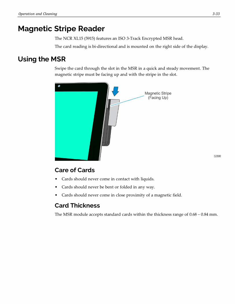
Magnetic Stripe ReaderThe NCR XL15 (5915) features an ISO 3-Track Encrypted MSR head.
The card reading is bi-directional and is mounted on the right side of the display.
Using the MSRSwipe the card through the slot in the MSR in a quick and steady movement. Themagnetic stripe must be facing up and with the stripe in the slot.
Care of Cards• Cards should never come in contact with liquids.
• Cards should never be bent or folded in any way.
• Cards should never come in close proximity of a magnetic field.
Card ThicknessThe MSR module accepts standard cards within the thickness range of 0.68 – 0.84 mm.

3-34 Operation and Cleaning
Cabinet Cleaning Procedures1. Disconnect the unit from the power outlet before cleaning.
2. Use a cloth lightly dampened with a mild detergent.
3. Do not use alcohol (methyl, ethyl, or isopropyl) or any strong dis-solvent. Do not usethinner or benzene, abrasive cleaners, or compressed air.
Warning: Do not use any other types of cleaners such as vinegar, solvents,degreasers, or ammonia-based cleaners. These can damage the unit.
4. Avoid getting liquids inside the unit. If liquid does get inside, have a qualifiedservice technician check it before you power it on again.
5. Remove external dust around the cooling vents.
Chapter 4: NCR Software OSD Utility
IntroductionThe NCR Software OSD is an application that is used to adjust display parameters, suchas Brightness, Contrast, and color. It also provides monitor identification information,such as the name, serial number, and manufacturer.
Supported FeaturesNote: Not all features are supported on every monitor. The button is inactive andgrayed out when the feature is not supported
• Brightness
• Contrast
• V Position
• H Position
• Phase
• Clock
• Red/Green/Green Video Gain
• Color Temperature
• Auto Setup
• Restore Default Settings
• V Moire
• H Moire
• V Size
• H Size

4-36 NCR Software OSD Utility
Installing the Utility1. Download the OSD Utility from the NCR website:
http://www.ncr.com
a. At this site, select the Support tab.
b. Select Drivers and Patches→ Retail Support Files→ NCR RealPOS andPeripherals→ Displays→ 5915.
c. Download the application.
There are several versions to choose from. There are GUI versions that are used torun locally on each system or Console versions for customers who want to run theapplication from a Command Line to many systems concurrently.
Windows• NCR_Software_OSD_GUI_x86 - (32-Bit)
• NCR_Software_OSD_Console_x86 - (32-Bit)
• NCR_Software_OSD_GUI_x64 - (64-Bit)
• NCR_Software_OSD_Console_x64 - (64-Bit)
Linux• NCR_Software_OSD_GUI_x86 - (32-Bit)
• NCR_Software_OSD_Console_x86 - (32-Bit)
2. Click on the version of choice and Save it on your local system.
3. Unzip the application to a folder of your choice on the target system.
4. In the unzipped folder, navigate to the OSD executable.
Example: (32-Bit GUI version)
NCR_Software_OSD_GUI_x86_V2.1.7.1 >> x86
5. Run the *.exe file.
NCR_Software_OSD_GUI_x86.exe >> [Enter]
6. Answer Yes at the Security warning.
NCR Software OSD Utility 4-37
Running the Utility (GUI Version)1. Unzip the application to a folder of your choice on the target system.
2. In the unzipped folder, navigate to the OSD executable.
Example: (32-Bit version)
NCR_Software_OSD_GUI_x86_V2.1.6.3>> x86
3. Execute the NCR_Software_OSD_GUI_x86.exe file to start the application.
4. Answer Yes at the Security warning.
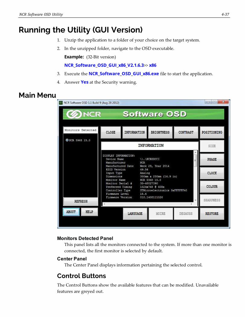
Main Menu
Monitors Detected PanelThis panel lists all the monitors connected to the system. If more than one monitor isconnected, the first monitor is selected by default.
Center PanelThe Center Panel displays information pertaining the selected control.
Control ButtonsThe Control Buttons show the available features that can be modified. Unavailablefeatures are greyed out.

4-38 NCR Software OSD Utility
Refresh ButtonRefreshes data in the Monitors Detected panel (OSD does not auto detect). Use thisbutton after connecting a new monitor to refresh the data.
About ButtonDisplays a brief description of the utility.
Help ButtonOpens the Help File.
Close ButtonCloses the OSD application
InformationProvides information about the selected monitor. Information includes:
• Device manufacturer
• Date manufactured
• EDID version
• Input type
• Dimensions
• Monitor name
• Monitor serial number
• Preferred timing
• Controller type
• Firmware level
• Firmware version (for Dynamo display only)
• Display mode (for Dynamo display only)
• Timing Report
• Horizontal frequency
• Vertical frequency
• Timing status
• Raw EDID
• Raw capabilities string (CAPS)
BrightnessProvides tools for adjusting Display brightness settings.
ContrastProvides tools for adjusting Display contrast settings.

NCR Software OSD Utility 4-39
PositioningProvides tools for gradually moving the image on the Display to a specific region(either left, right, up, or down).
SizeProvides tools for increasing or decreasing the height and width of the image on theDisplay.
PhaseProvides tools for increasing or decreasing the phase shift of the sampling clock.
ClockProvides tools for increasing or decreasing the video sampling clock frequency.
ColourProvides tools for adjusting Display color settings.
SharpnessProvides tools for increasing or decreasing the sharpness settings of the Display.
RestoreProvides the following functions:
• Auto Setup - sets horizontal position, vertical position, clock and phase.
• Auto Color - sets red/green/blue gain.
• Factory Defaults - restores all factory defaults including brightness, contrast, andcolor.
• Brightness/Contrast - restores factory defaults for brightness and contrast.
• Geometry Settings - restores factory defaults for geometry settings such ashorizontal position and vertical position.
• Colour Settings - restores factory defaults for colour settings.
DegaussProvides tools for CRT display to perform a degauss cycle.
MoireProvides tools for increasing or decreasing the vertical or horizontal moiré picturecancellation.
LanguageProvides listing of the supported languages and permits changing the OSDlanguage.

4-40 NCR Software OSD Utility
Display Adjustment ProceduresThe adjustment procedures are similar for most features. The color adjustment shownbelow is an example.
1. Select the Colour button.
2. The default Colour Settings menu has the 6500K radio button selected. To activatethe color slides select User1 .
3. Drag the slider to the right to increase the value of the property or to the left todecrease it. Alternatively, you can click on the "+" and "-" buttons.

NCR Software OSD Utility 4-41
Resetting Factory DefaultsShould the need arise the display settings can be reset to the factory defaults.
1. Select the Restore button.
2. All settings or just specific groups can be reset. Select the button of choice in theRestore window.
• Auto Setup - re-positions the window in the center of the display
• Factory Defaults - resets everything to the factory defaults
• Brightness/Contrast - resets the brightness and contrasts settings only
• Color Settings - resets the color settings only

4-42 NCR Software OSD Utility
Running the Utility (Console Version)1. Unzip the downloaded application to a folder of your choice on the target system.
2. In the unzipped folder, navigate to the OSD executable.
Example: (32-Bit version)
NCR_Software_OSD_Console_x86_V2.1.7.1 >> x86
3. Open a Command Line dialog window.
4. From the Command Line dialog, navigate to the OSD executable (*.exe) file.
5. Execute the file to start the application.
NCR_Software_OSD_Console_x86.exe >> [Enter]
A list of the available script command options are displayed, followed by severalexample scripts. If you need further assistance with creating scripts please contactyour NCR representative for help.
Chapter 5: Touchscreen Calibration
Only units with resistive touchscreens need to be calibrated. PCap displays donot require calibration.
Proper Touchscreen MethodsBefore performing the calibration procedure please observe the following guidelines forproper/improper methods of touching the screen.
• Face the monitor directly.
• Perform the calibration in the position (sitting or standing) that you normally expectto use the touch screen.
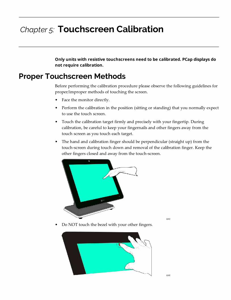
• Touch the calibration target firmly and precisely with your fingertip. Duringcalibration, be careful to keep your fingernails and other fingers away from thetouch screen as you touch each target.
• The hand and calibration finger should be perpendicular (straight up) from thetouch-screen during touch down and removal of the calibration finger. Keep theother fingers closed and away from the touch-screen.
• Do NOT touch the bezel with your other fingers.
5-44 Touch Screen Calibration
Calibrating the Touchscreen
Resistive Touchscreen Calibration1. Run the calibration program.
a. Open Windows Explorer.
b. Navigate to the calibration program.
C: >> Install >> Touch >> Drivers >> Resistive Touch Calibartion
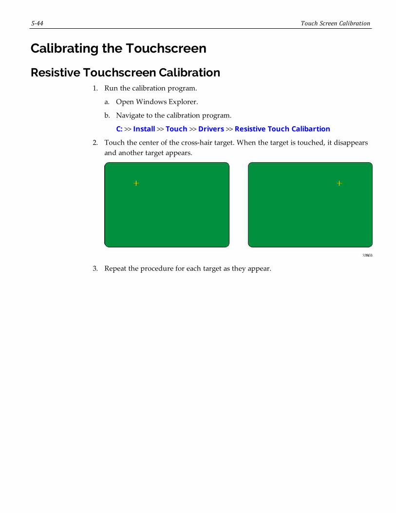
2. Touch the center of the cross-hair target. When the target is touched, it disappearsand another target appears.
3. Repeat the procedure for each target as they appear.