Embed Size (px)
Citation preview
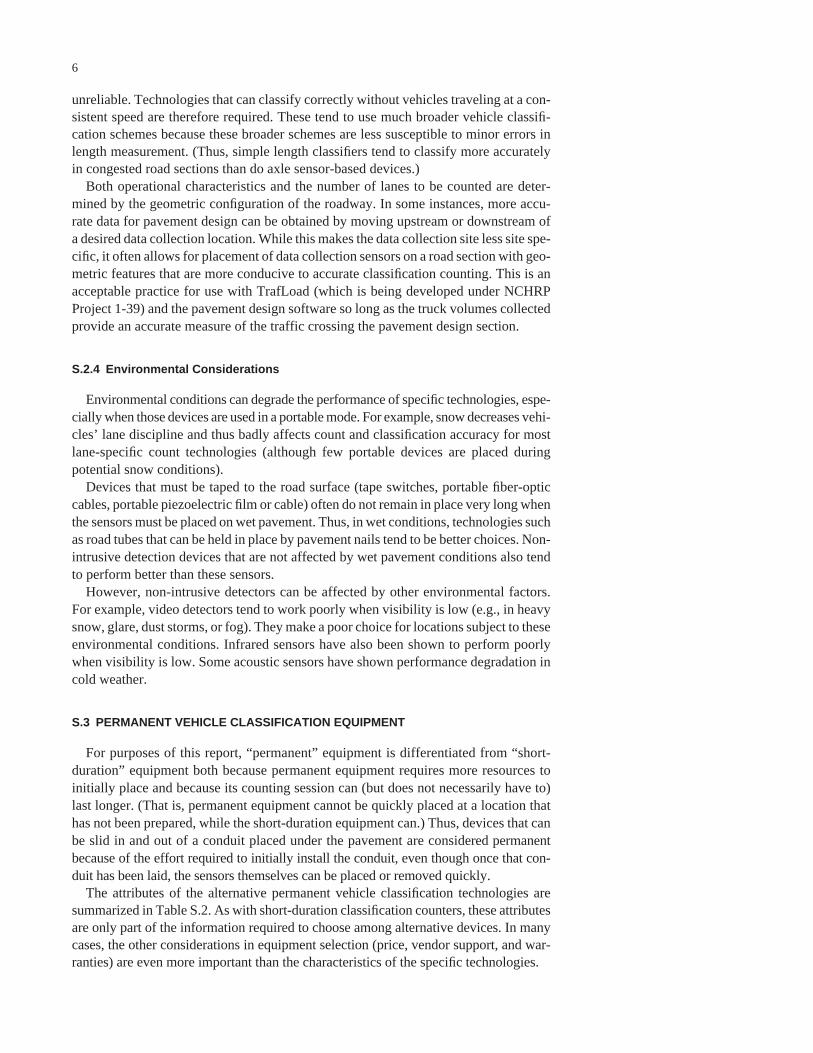
Equipment forCollecting Traffic
Load Data
NATIONALCOOPERATIVE HIGHWAYRESEARCH PROGRAMNCHRP
REPORT 509

TRANSPORTATION RESEARCH BOARD EXECUTIVE COMMITTEE 2004 (Membership as of January 2004)
OFFICERSChair: Michael S. Townes, President and CEO, Hampton Roads Transit, Hampton, VAVice Chair: Joseph H. Boardman, Commissioner, New York State DOTExecutive Director: Robert E. Skinner, Jr., Transportation Research Board
MEMBERSMICHAEL W. BEHRENS, Executive Director, Texas DOTSARAH C. CAMPBELL, President, TransManagement, Inc., Washington, DCE. DEAN CARLSON, Director, Carlson Associates, Topeka, KSJOHN L. CRAIG, Director, Nebraska Department of RoadsDOUGLAS G. DUNCAN, President and CEO, FedEx Freight, Memphis, TNGENEVIEVE GIULIANO, Director, Metrans Transportation Center and Professor, School of Policy, Planning, and Development,
USC, Los AngelesBERNARD S. GROSECLOSE, JR., President and CEO, South Carolina State Ports AuthoritySUSAN HANSON, Landry University Professor of Geography, Graduate School of Geography, Clark UniversityJAMES R. HERTWIG, President, Landstar Logistics, Inc., Jacksonville, FLHENRY L. HUNGERBEELER, Director, Missouri DOTADIB K. KANAFANI, Cahill Professor of Civil Engineering, University of California, Berkeley RONALD F. KIRBY, Director of Transportation Planning, Metropolitan Washington Council of GovernmentsHERBERT S. LEVINSON, Principal, Herbert S. Levinson Transportation Consultant, New Haven, CTSUE MCNEIL, Director, Urban Transportation Center and Professor, College of Urban Planning and Public Affairs,
University of Illinois, ChicagoMICHAEL D. MEYER, Professor, School of Civil and Environmental Engineering, Georgia Institute of TechnologyKAM MOVASSAGHI, Secretary of Transportation, Louisiana Department of Transportation and DevelopmentCAROL A. MURRAY, Commissioner, New Hampshire DOTJOHN E. NJORD, Executive Director, Utah DOTDAVID PLAVIN, President, Airports Council International, Washington, DCJOHN REBENSDORF, Vice President, Network and Service Planning, Union Pacific Railroad Co., Omaha, NEPHILIP A. SHUCET, Commissioner, Virginia DOTC. MICHAEL WALTON, Ernest H. Cockrell Centennial Chair in Engineering, University of Texas, AustinLINDA S. WATSON, General Manager, Corpus Christi Regional Transportation Authority, Corpus Christi, TX
MARION C. BLAKEY, Federal Aviation Administrator, U.S.DOT (ex officio)SAMUEL G. BONASSO, Acting Administrator, Research and Special Programs Administration, U.S.DOT (ex officio)REBECCA M. BREWSTER, President and COO, American Transportation Research Institute, Smyrna, GA (ex officio)GEORGE BUGLIARELLO, Chancellor, Polytechnic University and Foreign Secretary, National Academy of Engineering
(ex officio)THOMAS H. COLLINS (Adm., U.S. Coast Guard), Commandant, U.S. Coast Guard (ex officio)JENNIFER L. DORN, Federal Transit Administrator, U.S.DOT (ex officio)ROBERT B. FLOWERS (Lt. Gen., U.S. Army), Chief of Engineers and Commander, U.S. Army Corps of Engineers (ex officio)EDWARD R. HAMBERGER, President and CEO, Association of American Railroads (ex officio)JOHN C. HORSLEY, Executive Director, American Association of State Highway and Transportation Officials (ex officio)RICK KOWALEWSKI, Deputy Director, Bureau of Transportation Statistics, U.S.DOT (ex officio)WILLIAM W. MILLAR, President, American Public Transportation Association (ex officio) MARY E. PETERS, Federal Highway Administrator, U.S.DOT (ex officio)SUZANNE RUDZINSKI, Director, Transportation and Regional Programs, U.S. Environmental Protection Agency (ex officio)JEFFREY W. RUNGE, National Highway Traffic Safety Administrator, U.S.DOT (ex officio)ALLAN RUTTER, Federal Railroad Administrator, U.S.DOT (ex officio)ANNETTE M. SANDBERG, Federal Motor Carrier Safety Administrator, U.S.DOT (ex officio)WILLIAM G. SCHUBERT, Maritime Administrator, U.S.DOT (ex officio)ROBERT A. VENEZIA, Program Manager of Public Health Applications, National Aeronautics and Space Administration
(ex officio)
NATIONAL COOPERATIVE HIGHWAY RESEARCH PROGRAM
Transportation Research Board Executive Committee Subcommittee for NCHRPMICHAEL S. TOWNES, Hampton Roads Transit, Hampton, VA
(Chair)JOSEPH H. BOARDMAN, New York State DOTGENEVIEVE GIULIANO, University of Southern California,
Los Angeles
JOHN C. HORSLEY, American Association of State Highway andTransportation Officials
MARY E. PETERS, Federal Highway Administration ROBERT E. SKINNER, JR., Transportation Research BoardC. MICHAEL WALTON, University of Texas, Austin
T R A N S P O R T A T I O N R E S E A R C H B O A R DWASHINGTON, D.C.
2004www.TRB.org
NATIONAL COOPERATIVE HIGHWAY RESEARCH PROGRAM
NCHRP REPORT 509
Research Sponsored by the American Association of State Highway and Transportation Officials in Cooperation with the Federal Highway Administration
SUBJECT AREAS
Planning and Administration • Pavement Design, Management, and Performance •
Bridges, Other Structures, and Hydraulics and Hydrology
Equipment forCollecting Traffic
Load Data
MARK HALLENBECK
Washington State Transportation Center
University of Washington
Seattle, WA
AND
HERBERT WEINBLATT
Cambridge Systematics, Inc.
Chevy Chase, MD
NATIONAL COOPERATIVE HIGHWAY RESEARCH PROGRAM
Systematic, well-designed research provides the most effectiveapproach to the solution of many problems facing highwayadministrators and engineers. Often, highway problems are of localinterest and can best be studied by highway departmentsindividually or in cooperation with their state universities andothers. However, the accelerating growth of highway transportationdevelops increasingly complex problems of wide interest tohighway authorities. These problems are best studied through acoordinated program of cooperative research.
In recognition of these needs, the highway administrators of theAmerican Association of State Highway and TransportationOfficials initiated in 1962 an objective national highway researchprogram employing modern scientific techniques. This program issupported on a continuing basis by funds from participatingmember states of the Association and it receives the full cooperationand support of the Federal Highway Administration, United StatesDepartment of Transportation.
The Transportation Research Board of the National Academieswas requested by the Association to administer the researchprogram because of the Board’s recognized objectivity andunderstanding of modern research practices. The Board is uniquelysuited for this purpose as it maintains an extensive committeestructure from which authorities on any highway transportationsubject may be drawn; it possesses avenues of communications andcooperation with federal, state and local governmental agencies,universities, and industry; its relationship to the National ResearchCouncil is an insurance of objectivity; it maintains a full-timeresearch correlation staff of specialists in highway transportationmatters to bring the findings of research directly to those who are ina position to use them.
The program is developed on the basis of research needsidentified by chief administrators of the highway and transportationdepartments and by committees of AASHTO. Each year, specificareas of research needs to be included in the program are proposedto the National Research Council and the Board by the AmericanAssociation of State Highway and Transportation Officials.Research projects to fulfill these needs are defined by the Board, andqualified research agencies are selected from those that havesubmitted proposals. Administration and surveillance of researchcontracts are the responsibilities of the National Research Counciland the Transportation Research Board.
The needs for highway research are many, and the NationalCooperative Highway Research Program can make significantcontributions to the solution of highway transportation problems ofmutual concern to many responsible groups. The program,however, is intended to complement rather than to substitute for orduplicate other highway research programs.
Note: The Transportation Research Board of the National Academies, theNational Research Council, the Federal Highway Administration, the AmericanAssociation of State Highway and Transportation Officials, and the individualstates participating in the National Cooperative Highway Research Program donot endorse products or manufacturers. Trade or manufacturers’ names appearherein solely because they are considered essential to the object of this report.
Published reports of the
NATIONAL COOPERATIVE HIGHWAY RESEARCH PROGRAM
are available from:
Transportation Research BoardBusiness Office500 Fifth Street, NWWashington, DC 20001
and can be ordered through the Internet at:
http://www.national-academies.org/trb/bookstore
Printed in the United States of America
NCHRP REPORT 509
Project 1-39 FY’00
ISSN 0077-5614
ISBN 0-309-08788-0
Library of Congress Control Number 2004100961
© 2004 Transportation Research Board
Price $20.00
NOTICE
The project that is the subject of this report was a part of the National Cooperative
Highway Research Program conducted by the Transportation Research Board with the
approval of the Governing Board of the National Research Council. Such approval
reflects the Governing Board’s judgment that the program concerned is of national
importance and appropriate with respect to both the purposes and resources of the
National Research Council.
The members of the technical committee selected to monitor this project and to review
this report were chosen for recognized scholarly competence and with due
consideration for the balance of disciplines appropriate to the project. The opinions and
conclusions expressed or implied are those of the research agency that performed the
research, and, while they have been accepted as appropriate by the technical committee,
they are not necessarily those of the Transportation Research Board, the National
Research Council, the American Association of State Highway and Transportation
Officials, or the Federal Highway Administration, U.S. Department of Transportation.
Each report is reviewed and accepted for publication by the technical committee
according to procedures established and monitored by the Transportation Research
Board Executive Committee and the Governing Board of the National Research
Council.

The National Academy of Sciences is a private, nonprofit, self-perpetuating society of distinguished schol-ars engaged in scientific and engineering research, dedicated to the furtherance of science and technology and to their use for the general welfare. On the authority of the charter granted to it by the Congress in 1863, the Academy has a mandate that requires it to advise the federal government on scientific and techni-cal matters. Dr. Bruce M. Alberts is president of the National Academy of Sciences.
The National Academy of Engineering was established in 1964, under the charter of the National Acad-emy of Sciences, as a parallel organization of outstanding engineers. It is autonomous in its administration and in the selection of its members, sharing with the National Academy of Sciences the responsibility for advising the federal government. The National Academy of Engineering also sponsors engineering programs aimed at meeting national needs, encourages education and research, and recognizes the superior achieve-ments of engineers. Dr. William A. Wulf is president of the National Academy of Engineering.
The Institute of Medicine was established in 1970 by the National Academy of Sciences to secure the services of eminent members of appropriate professions in the examination of policy matters pertaining to the health of the public. The Institute acts under the responsibility given to the National Academy of Sciences by its congressional charter to be an adviser to the federal government and, on its own initiative, to identify issues of medical care, research, and education. Dr. Harvey V. Fineberg is president of the Institute of Medicine.
The National Research Council was organized by the National Academy of Sciences in 1916 to associate the broad community of science and technology with the Academy’s purposes of furthering knowledge and advising the federal government. Functioning in accordance with general policies determined by the Acad-emy, the Council has become the principal operating agency of both the National Academy of Sciences and the National Academy of Engineering in providing services to the government, the public, and the scientific and engineering communities. The Council is administered jointly by both the Academies and the Institute of Medicine. Dr. Bruce M. Alberts and Dr. William A. Wulf are chair and vice chair, respectively, of the National Research Council.
The Transportation Research Board is a division of the National Research Council, which serves the National Academy of Sciences and the National Academy of Engineering. The Board’s mission is to promote innovation and progress in transportation through research. In an objective and interdisciplinary setting, the Board facilitates the sharing of information on transportation practice and policy by researchers and practitioners; stimulates research and offers research management services that promote technical excellence; provides expert advice on transportation policy and programs; and disseminates research results broadly and encourages their implementation. The Board’s varied activities annually engage more than 4,000 engineers, scientists, and other transportation researchers and practitioners from the public and private sectors and academia, all of whom contribute their expertise in the public interest. The program is supported by state transportation departments, federal agencies including the component administrations of the U.S. Department of Transportation, and other organizations and individuals interested in the development of transportation. www.TRB.org
www.national-academies.org

COOPERATIVE RESEARCH PROGRAMS STAFF FOR NCHRP REPORT 509
ROBERT J. REILLY, Director, Cooperative Research ProgramsCRAWFORD F. JENCKS, Manager, National Cooperative Highway Research ProgramAMIR N. HANNA, Senior Program OfficerEILEEN P. DELANEY, Managing EditorBETH HATCH, Assistant EditorELLEN M. CHAFEE, Assistant Editor
NCHRP PROJECT 1-39 PANELField of Design—Area of Pavements
DANNY A. DAWOOD, Pennsylvania DOT (Chair)KENNETH W. FULTS, Texas DOT CHARLES K. CEROCKE, Nevada DOTHARSHAD DESAI, Florida DOTRALPH A. GILLMANN, FHWAJERRY LEGG, West Virginia DOTTED SCOTT, Roadway Express, Inc., Alexandria, VAANDREW WILLIAMS, JR., Ohio DOTLARRY WISER, FHWA Liaison RepresentativeSTEPHEN F. MAHER, TRB Liaison RepresentativeA. ROBERT RAAB, TRB Liaison Representative

This report identifies the key issues that must be considered by state and other high-way operating agencies in selecting traffic equipment for collecting the truck volumesand load spectra needed for analysis and design of pavement structures. The report alsoidentifies steps that must be taken to ensure that the equipment performs appropriatelyand that, as a consequence, the data collected accurately describe the vehicles beingmonitored. The report is a useful resource for state personnel and others involved in theplanning and design of highway pavements and structures.
Traffic information is one of the key data elements required for the design andanalysis of pavement structures. In the procedure used in the 1993 AASHTO Guide forDesign of Pavement Structures, a mixed traffic stream of different axle loads and axleconfigurations is converted into a design traffic number by converting each expectedaxle load into an equivalent number of 18-kip, single-axle loads, known as equivalentsingle-axle loads (ESALs). Equivalency factors are used to determine the number ofESALs for each axle load and axle configuration. These factors are based on the pres-ent serviceability index (PSI) concept and depend on the pavement type and structure.Studies have shown that these factors also are influenced by pavement condition, dis-tress type, failure mode, and other parameters.
A more direct and rational approach to the analysis and design of pavement struc-tures involves procedures that use mechanistic-empirical principles to estimate theeffects of actual traffic on pavement response and distress. This approach has been usedto develop a guide for the mechanistic-empirical design of new and rehabilitated pave-ment structures as part of NCHRP Project 1-37A. The mechanistic-based distress pre-diction models used in this guide will require specific data for each axle type and axleload group. Recognizing the constraints on resources available in state and local high-way agencies for traffic data collection, the guide will allow for various levels of traf-fic data collection and analysis.
Because the anticipated guide will use traffic data inputs that differ from those cur-rently used in pavement design and analysis, there was an apparent need for researchto provide clear information on traffic data and forecasting and to provide guidance onselection and operation of the equipment needed for collecting these data. This infor-mation will facilitate use of the anticipated guide. NCHRP Project 1-39 was conductedto address this need.
Under NCHRP Project 1-39, “Traffic Data Collection, Analysis, and Forecastingfor Mechanistic Pavement Design,” Cambridge Systematics, Inc., was assigned theobjectives of (1) developing guidelines for collecting and forecasting traffic data toformulate load spectra for use in procedures proposed in the guide for mechanistic-empirical design and (2) providing guidance on selecting, installing, and operating traf-fic data collection equipment and handling traffic data. This report is concerned with
FOREWORDBy Amir N. Hanna
Staff OfficerTransportation Research
Board
the latter objective; the first objective will be addressed in detail in the agency’s finalreport on the project.
To accomplish the latter objective, the researchers identified the steps required toselect the equipment necessary for collecting traffic load data. In these steps, theresearchers identified the types of equipment available for collecting classificationcounts and for weighing vehicles in motion and provided detailed descriptions of var-ious technologies. As part of these descriptions, the researchers reviewed the strengthsand weaknesses of each technology. Finally, the researchers provided guidance onselection of equipment by considering (1) data collection needs of users, (2) data han-dling requirements and capabilities, and (3) characteristics of available technologies.To facilitate implementation and use of equipment, the researchers also provided infor-mation on best practices for equipment use.
The information contained in this report should be of interest to those involved inthe planning and design of highway pavements and structures. It will be particularlyuseful to agencies contemplating collection of traffic data for use in conjunction withthe guide for the mechanistic-empirical design of new and rehabilitated pavementstructures.

1 SUMMARY
16 CHAPTER 1 Introduction
17 CHAPTER 2 Types of Equipment2.1 Vehicle Classification, 172.2 WIM Data, 18
21 CHAPTER 3 Technology Descriptions3.1 Vehicle Classification, 213.2 WIM, 33
41 CHAPTER 4 A Process for Selecting Equipment4.1 Data Collection Needs, 414.2 Data Handling and Other Agency Considerations, 434.3 Understanding Equipment Characteristics, 43
46 CHAPTER 5 Best Practices for Equipment Use5.1 Identify User Requirements, 465.2 Determine Site Location and System Requirements, 475.3 Determine Design Life and Accuracy Requirements, 485.4 Budget Necessary Resources, 495.5 Develop, Use, and Maintain a Quality Assurance Program, 505.6 Purchase Equipment with a Warranty, 525.7 Manage Equipment Installation, 535.8 Calibrate and Maintain Calibration of Equipment, 535.9 Conduct Preventive and Corrective Maintenance, 57
CONTENTS
The traffic load data that are key to the design of pavement structures include truckvolumes and the load spectra for those volumes. These data are obtained by countingtrucks by class and by weighing a sample of trucks to obtain the load spectra associ-ated with each class of truck. Therefore, data collection equipment must allow for col-lecting both types of data.
Weigh-in-motion (WIM) data collection equipment collects both truck volume andload spectra, but the equipment is more expensive to obtain and more difficult to installand operate than equipment that can only count and classify vehicles. Therefore, high-way agencies routinely use a combination of WIM and simpler vehicle classificationequipment to collect the data they require for pavement design.
This report summarizes the key issues and information needed by a state or otherhighway operating agency to select the equipment it needs to perform these tasks. Italso summarizes the steps that must be taken to ensure that the equipment selectedworks as intended and that, as a consequence, the data collected accurately describe thevehicle fleet being measured.
S.1 BASIC EQUIPMENT NEEDS
A combination of permanent and portable data collection is needed to provide thetraffic load data required for pavement design. Permanent devices provide more exten-sive datasets and are generally necessary for collecting the data needed to understandchanges in traffic patterns associated with different days of the week and months of theyear. Portable devices allow flexibility in collecting data and help ensure that data arecollected from specific locations of interest. Portable devices also tend to lower the costof collecting the geographically diverse and site-specific data needed to develop accu-rate pavement design loads.
Therefore, a combination of devices—WIM and classification, permanent andportable—are needed to meet their traffic data collection needs for pavement design.Further expanding the need for diversity in the devices that many states will purchaseand use is the fact that different technologies have different strengths and weaknesses.Some equipment works nearly flawlessly in rural areas and in moderate environmental
SUMMARY
EQUIPMENT FOR COLLECTING TRAFFIC LOAD DATA

conditions, but that same equipment may work poorly in urban stop-and-go traffic orwhere snow conditions disrupt driver lane discipline. Other devices work less accu-rately under the best of conditions but can still operate effectively in harsh data collec-tion conditions such as stop-and-go traffic or adverse weather. Making these tradeoffsis the most difficult part of selecting equipment.
To make these tradeoffs correctly, and then to ensure that the selected equipmentoperates as intended, requires knowledge. Required areas of knowledge and necessarydecisions and/or actions include the following:
• Understanding the equipment’s capabilities and limitations;• Understanding the data collection site’s characteristics;• Choosing data collection locations that provide the best opportunity for collecting
accurate data;• Selecting equipment for each site that can operate effectively in the traffic and
environmental conditions present at that site;• Understanding how data collected from two different devices relate to each other
(i.e., are the vehicle classes collected by two different classifiers the same, and ifnot, how do those classes relate to each other?);
• Installing the equipment correctly;• Understanding how to test the equipment once it is in place to ensure that it is oper-
ating as intended and ensuring that these procedures are followed;• Properly calibrating the equipment after it has been installed;• Understanding preventive and corrective “site” maintenance;• Performing quality control checks on the data produced by those devices; and• Repairing, re-calibrating, or otherwise adjusting the equipment and site conditions
if quality assurance checks indicate that problems are occurring.
While the choice of sensor technology can affect the accuracy of the data collectedas well as the cost and longevity of the data collection installation, a wide body ofresearch shows that technology is only one of many factors that affect the reliability ofcollected data. In fact, recent work done for the Federal Highway Administration(FHWA) concluded that “In general the differences between devices from differentmanufacturers were more significant than differences between technologies.” Thereport also stated that “It is more important to select a well designed and highly reli-able product than to narrow a selection to a particular technology.”1
This is not to say that technology choice is unimportant. Each technology has specificstrengths and weaknesses. Understanding those strengths and weaknesses allows a high-way agency to select equipment that is more likely to work in a specific situation. Whiledifferent vendors are often capable of designing around a given technology’s weaknesses,the odds of obtaining accurate data are certainly increased by taking advantage of spe-cific technology strengths and avoiding known technology weaknesses. At the same time,as noted in the aforementioned FHWA study, some vendors do a poor job of imple-menting specific technologies. In addition, even the best technology from the best ven-dor will not work accurately if the device is poorly installed, maintained, or calibrated.
The rest of this report describes an equipment selection process that guides interestedparties toward the technologies that have demonstrated (in the literature published todate) specific strengths and away from technologies that have demonstrated specificweaknesses. Note that (1) this review is not universal (some data collection technolo-
2
1 Field Test of Monitoring of Urban Vehicle Operations Using Non-Intrusive Technologies, FHWA, May 1997, FHWA-PL-97-018,by Minnesota DOT and SRF Consulting.
3
gies have undoubtedly been missed) and (2) data collection technology continues toevolve with time. Specific devices may come to market that are either not part of thisreview or have different attributes from the technologies reviewed in this report. There-fore, highway agencies are reminded to continually review available sources2 thatdescribe equipment performance, to communicate frequently with neighboring statesto learn about the performance of their data collection equipment and their experienceswith vendors, and to monitor the performance of their equipment to ensure that it oper-ates as intended.
S.2 SHORT-DURATION VEHICLE CLASSIFICATION EQUIPMENT
The primary technological attributes that should be considered when short-durationvehicle classification equipment is selected include the following:
• Whether the vehicle (tire) sensors need to be placed on the road surface or willmeasure from above or beside the pavement,
• The type of vehicle classes that can be collected by the device,• The number of lanes that each device can observe, and• The effects that specific environmental conditions will have on equipment perfor-
mance.
These attributes are summarized in Table S.1 for the technologies commonly found on themarket in 2002.
To select equipment, the highway agency must also consider the cost of the equip-ment (capital, operations, maintenance, and other life-cycle cost considerations), theability to integrate the data collected by a specific device into the state’s traffic datamanagement system (how the vendor’s data retrieval software/system works andwhether it integrates easily with the state’s system), and the various support servicesand assurances offered by specific vendors, including warranties and other guarantiesof performance, proof of previous successful performance (independent testing), thelevel of technical support offered, and the availability of training. In many cases, theseadditional factors are the deciding factor in equipment selection, especially when twoalternative technologies have similar operating characteristics.
All of the above factors are interrelated. In addition, each can be the deciding factorin an equipment selection decision. Thus, no single piece of equipment is always thebest choice, and no single, simple decision process will lead to the correct equipmentchoice. The state must weigh the relative importance of these attributes each time itselects equipment.
S.2.1 Intrusive or Non-Intrusive Sensors
Perhaps the first question that should be asked when deciding between intrusive andnon-intrusive equipment is “Can the portable equipment be safely installed in the road-way section in question?” In most cases, intrusive sensors provide more descriptivevehicle classification data than non-intrusive sensors, especially where the sensors pro-vide axle count and spacing information. They are therefore normally better options forportable classification counts than non-intrusive sensors if they can be safely placed onthe road surface.
2 On-line resources are provided at the end of this summary, as are references to some conventionally published works.
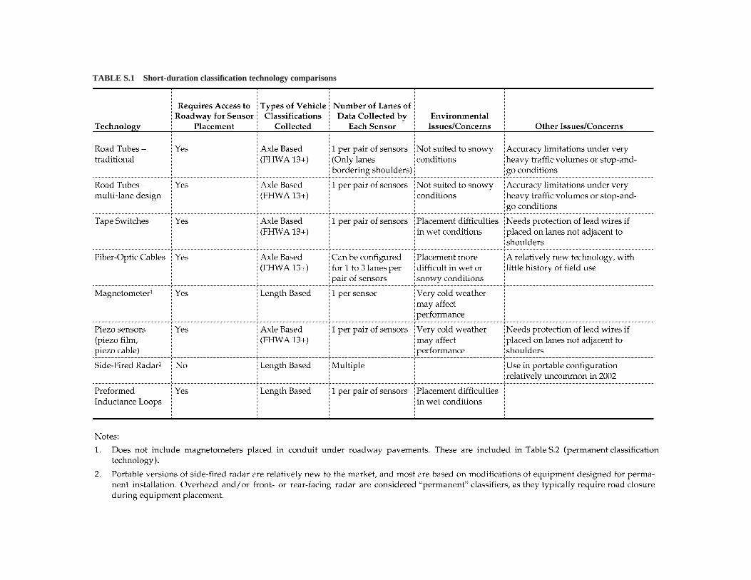
TABLE S.1 Short-duration classification technology comparisons
5
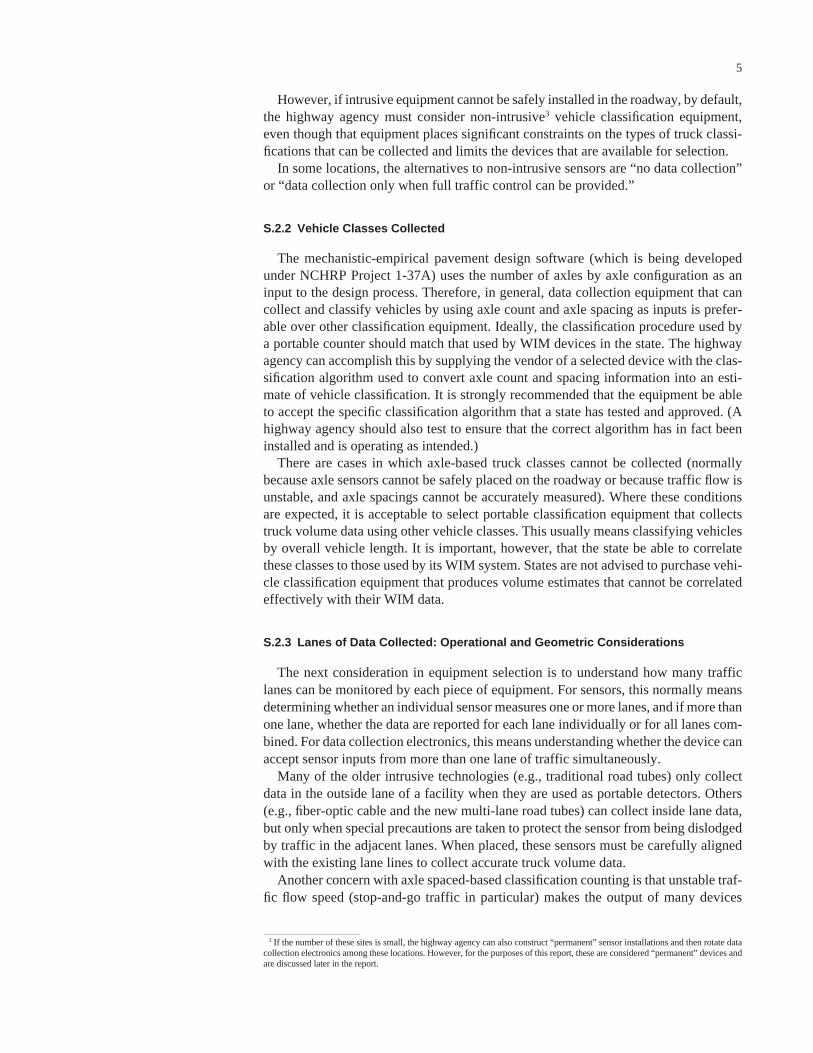
However, if intrusive equipment cannot be safely installed in the roadway, by default,the highway agency must consider non-intrusive3 vehicle classification equipment,even though that equipment places significant constraints on the types of truck classi-fications that can be collected and limits the devices that are available for selection.
In some locations, the alternatives to non-intrusive sensors are “no data collection”or “data collection only when full traffic control can be provided.”
S.2.2 Vehicle Classes Collected
The mechanistic-empirical pavement design software (which is being developedunder NCHRP Project 1-37A) uses the number of axles by axle configuration as aninput to the design process. Therefore, in general, data collection equipment that cancollect and classify vehicles by using axle count and axle spacing as inputs is prefer-able over other classification equipment. Ideally, the classification procedure used bya portable counter should match that used by WIM devices in the state. The highwayagency can accomplish this by supplying the vendor of a selected device with the clas-sification algorithm used to convert axle count and spacing information into an esti-mate of vehicle classification. It is strongly recommended that the equipment be ableto accept the specific classification algorithm that a state has tested and approved. (Ahighway agency should also test to ensure that the correct algorithm has in fact beeninstalled and is operating as intended.)
There are cases in which axle-based truck classes cannot be collected (normallybecause axle sensors cannot be safely placed on the roadway or because traffic flow isunstable, and axle spacings cannot be accurately measured). Where these conditionsare expected, it is acceptable to select portable classification equipment that collectstruck volume data using other vehicle classes. This usually means classifying vehiclesby overall vehicle length. It is important, however, that the state be able to correlatethese classes to those used by its WIM system. States are not advised to purchase vehi-cle classification equipment that produces volume estimates that cannot be correlatedeffectively with their WIM data.
S.2.3 Lanes of Data Collected: Operational and Geometric Considerations
The next consideration in equipment selection is to understand how many trafficlanes can be monitored by each piece of equipment. For sensors, this normally meansdetermining whether an individual sensor measures one or more lanes, and if more thanone lane, whether the data are reported for each lane individually or for all lanes com-bined. For data collection electronics, this means understanding whether the device canaccept sensor inputs from more than one lane of traffic simultaneously.
Many of the older intrusive technologies (e.g., traditional road tubes) only collectdata in the outside lane of a facility when they are used as portable detectors. Others(e.g., fiber-optic cable and the new multi-lane road tubes) can collect inside lane data,but only when special precautions are taken to protect the sensor from being dislodgedby traffic in the adjacent lanes. When placed, these sensors must be carefully alignedwith the existing lane lines to collect accurate truck volume data.
Another concern with axle spaced-based classification counting is that unstable traf-fic flow speed (stop-and-go traffic in particular) makes the output of many devices
3 If the number of these sites is small, the highway agency can also construct “permanent” sensor installations and then rotate datacollection electronics among these locations. However, for the purposes of this report, these are considered “permanent” devices andare discussed later in the report.
unreliable. Technologies that can classify correctly without vehicles traveling at a con-sistent speed are therefore required. These tend to use much broader vehicle classifi-cation schemes because these broader schemes are less susceptible to minor errors inlength measurement. (Thus, simple length classifiers tend to classify more accuratelyin congested road sections than do axle sensor-based devices.)
Both operational characteristics and the number of lanes to be counted are deter-mined by the geometric configuration of the roadway. In some instances, more accu-rate data for pavement design can be obtained by moving upstream or downstream ofa desired data collection location. While this makes the data collection site less site spe-cific, it often allows for placement of data collection sensors on a road section with geo-metric features that are more conducive to accurate classification counting. This is anacceptable practice for use with TrafLoad (which is being developed under NCHRPProject 1-39) and the pavement design software so long as the truck volumes collectedprovide an accurate measure of the traffic crossing the pavement design section.
S.2.4 Environmental Considerations
Environmental conditions can degrade the performance of specific technologies, espe-cially when those devices are used in a portable mode. For example, snow decreases vehi-cles’ lane discipline and thus badly affects count and classification accuracy for mostlane-specific count technologies (although few portable devices are placed duringpotential snow conditions).
Devices that must be taped to the road surface (tape switches, portable fiber-opticcables, portable piezoelectric film or cable) often do not remain in place very long whenthe sensors must be placed on wet pavement. Thus, in wet conditions, technologies suchas road tubes that can be held in place by pavement nails tend to be better choices. Non-intrusive detection devices that are not affected by wet pavement conditions also tendto perform better than these sensors.
However, non-intrusive detectors can be affected by other environmental factors.For example, video detectors tend to work poorly when visibility is low (e.g., in heavysnow, glare, dust storms, or fog). They make a poor choice for locations subject to theseenvironmental conditions. Infrared sensors have also been shown to perform poorlywhen visibility is low. Some acoustic sensors have shown performance degradation incold weather.
S.3 PERMANENT VEHICLE CLASSIFICATION EQUIPMENT
For purposes of this report, “permanent” equipment is differentiated from “short-duration” equipment both because permanent equipment requires more resources toinitially place and because its counting session can (but does not necessarily have to)last longer. (That is, permanent equipment cannot be quickly placed at a location thathas not been prepared, while the short-duration equipment can.) Thus, devices that canbe slid in and out of a conduit placed under the pavement are considered permanentbecause of the effort required to initially install the conduit, even though once that con-duit has been laid, the sensors themselves can be placed or removed quickly.
The attributes of the alternative permanent vehicle classification technologies aresummarized in Table S.2. As with short-duration classification counters, these attributesare only part of the information required to choose among alternative devices. In manycases, the other considerations in equipment selection (price, vendor support, and war-ranties) are even more important than the characteristics of the specific technologies.
6
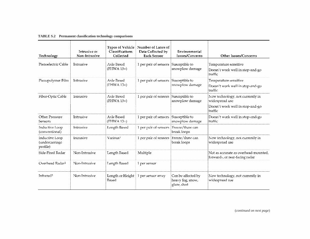
TABLE S.2 Permanent classification technology comparisons
(continued on next page)
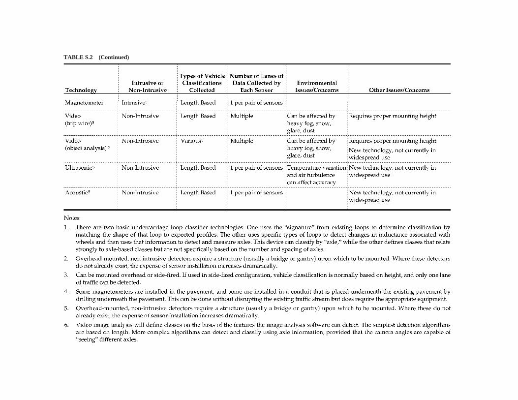
TABLE S.2 (Continued)
9
S.3.1 Choosing Between Intrusive and Non-Intrusive Sensors
As with short-duration classifiers, a key consideration is whether conditions requirethe use of non-intrusive sensors. As with short-duration counts, the primary drawbackof non-intrusive sensors is that very few devices directly measure the number and con-figuration of axles. This reduces the accuracy of vehicle classification count informa-tion for the purpose of pavement design. However, there are conditions when this lossof pavement design accuracy is warranted. These conditions occur where pavement orenvironmental conditions would result in poor performance of intrusive, axle-basedclassifiers or where location considerations reduce the cost of non-intrusive sensors sig-nificantly relative to the cost of intrusive sensors.
For example, non-intrusive sensors are particularly advantageous for locationswhere lane geometry will soon change. Because they are non-intrusive, changing thefocal point (the exact space at which the sensor points and collects data) for most non-intrusive devices is fairly simple. This is not true for most permanently mounted, intru-sive devices. Thus, if a roadway will be restriped as part of an ongoing, long-term con-struction project, the choice of non-intrusive sensors makes sense. With intrusivesensors, the sensors initially placed are generally useless in the new lane configuration(they often cover parts of two lanes) and must be either dug up or abandoned. (Few sen-sors can be dug up and then reused.) It makes far better economic sense to place non-intrusive sensors in such a location, even though the data collected are less precise thandesired, rather than either not collect data or purchase and install two complete sets ofintrusive sensors.
With permanent counter equipment, usually the need for a long-term data collectionsite makes a highway agency willing to perform the tasks necessary to install sensorsin the roadway on all lanes of a facility, regardless of roadway geometry. (For exam-ple, the agency will cut slots in the outside lane pavement to protect lead wires leadingto sensors that monitor traffic on the inside lanes.) Thus, unlike with short-durationcounts, the geometric configuration of a roadway, by itself, is unlikely to cause a stateto select non-intrusive sensors over intrusive sensors.
On the other hand, because permanent equipment operates year-round, weather andenvironmental sensitivity become bigger issues. In locations that experience frequent,heavy snowfall and a resulting decline in driver lane discipline, considerable data canbe lost if lane-specific axle sensors are selected. In addition, with sensors that operateyear-round, states must determine whether the sensors they select will function in thetemperatures expected. For example, piezoceramic cable loses sensitivity in very coldweather. Consequently, states that wish to place sensors in a location that will experi-ence temperatures well below freezing must obtain both documented proof and war-ranties from their vendors that the selected equipment will operate correctly at theexpected temperatures.
S.3.2 Sensor Longevity and Pavement Condition
A second situation in which non-intrusive sensors may be preferable to intrusive sen-sors is where the pavement condition is poor enough now, or will be in the near future,to raise doubts about the expected life of intrusive sensors and/or where the pavementcondition could affect the accuracy of those sensors.
Poor pavement condition can dramatically shorten the life span of intrusive sensors.This is partly because poor pavement conditions increase vehicle dynamics, which inturn increase the impact loads applied to intrusive sensors. But poor pavement condi-tion also commonly leads to premature failure of the pavement/sensor bond, and the
loss of this bond normally results in a non-functional sensor (and often the loss of thesensor itself, because most sensors cannot be reinstalled).
Even if the sensor has not failed, pavement failure around the sensor can lead to thegeneration of “stray” signals within the sensor. One common form of these signals is“ghost axles” generated in piezoelectric cables when neighboring concrete slabs rockbecause of failure of the joints between slabs. Stray signals frequently result in mis-classification of vehicles, collection of invalid vehicle records, and ultimately the cre-ation of datasets containing so many invalid data that they become unusable.
If the pavement condition at a proposed permanent data collection site is poor, thereare three major options: repave the roadway section that will hold the sensor beforeinstalling that sensor; choose a non-intrusive sensor whose performance is not affectedby pavement condition; or select a lower-cost intrusive sensor technology recognizingthat the life span of that sensor will be fairly short.
The last of these options is often a cost-effective way of collecting a valuable data-set needed for very accurate pavement design, but it requires acknowledgment that thesensor will be lost in a shorter period than most states expect their permanent equip-ment to last. It also means that great care must to be taken to (1) review data from thedevice placed at this location to ensure that it works accurately when it is originallyplaced and then (2) identify when sensor accuracy starts to degrade as the pavementcondition continues to deteriorate. Therefore, in these conditions, added quality con-trol and data review are needed both when the sensor is first installed and then as thedevice continues to operate.
Pavement condition also changes how a highway agency might view the tradeoffsbetween sensor cost and performance. Poor pavement condition will significantlychange the life-cycle of all intrusive technologies. (For example, in some cases sensorswill fail before they reach their expected life because of pavement condition.) Whenpavement condition is poor or even marginal, paying more for a longer lived sensormakes no sense because the sensor failure will not be a function of the sensor itself. Con-sequently, pavement life should be considered when the life expectancy of a permanentsite is computed, and the cost/performance decision should be adjusted accordingly.
S.3.3 Vehicle Classes Collected
As with short-duration counts, the preferred vehicle classification scheme for per-manent classifiers is axle based, which means that, all things being equal, intrusive, axlesensor-based classifiers are the preferred technology for meeting the pavement designguide requirements for traffic load data. In fact, use of equipment that provides truck vol-umes that follow the same classification scheme as the state’s WIM devices results in themost accurate traffic load datasets possible and is recommended whenever practical.
However, many of the functions for which permanent classification data are collected(e.g., seasonal adjustment of short-duration counts) require only two or three classes oftrucks. Therefore, having permanent classifiers that collect only three or four classes ofvehicles is acceptable when axle-based classifiers are not practical or cost-effective.
Selecting a classifier technology that does not use the same classification algorithmas the WIM scales selected requires a careful determination of how the classificationschemes of these alternative devices correlate.
S.4 WEIGH-IN-MOTION EQUIPMENT
It is not possible to provide a simple decision process for selecting WIM equipment.In general, each highway agency must determine its own tradeoffs among the cost of
10
11
equipment and its installation, the cost of calibration, the expected life span of the WIMsensor, and the expected life span (and structural performance) of the pavement intowhich the equipment will be placed. These technical considerations must also be exam-ined in light of the compatibility of the data retrieval capabilities offered by specific ven-dors, how well those capabilities integrate with existing data collection software, thewarranties and other guaranties of performance offered with the equipment, the perfor-mance history of that equipment and its vendor, and the support services offered by thevendor. Key technology considerations are summarized in Table S.3. An important addi-tional consideration is whether the equipment offered by a vendor has been indepen-dently evaluated and found to meet the ASTM E 1318 WIM performance standards.
S.4.1 Technology Choice Versus Location Choice
The primary key to the success of any WIM system’s use is the location of the axleweighing sensors. Because vehicle dynamics play such a significant role in the forceactually applied by any given axle at any given point on the roadway, the selection ofthe location used to weigh trucks is often more important than the choice of a specifictechnology to ensure accurate axle weight data. The placement of a scale in rough,uneven pavement will result in poor quality weight data, regardless of the WIM tech-nology selected. Similarly, if the pavement condition at a WIM site deteriorates after ascale has been installed, the performance of that scale can be expected to deteriorate aswell, regardless of the technology selected.
Some scale sensor technologies rely on the structural strength of the pavement inwhich they are supported. When these sensors are placed in weak pavement (i.e., pave-ment that flexes), the accuracy of these sensors tends to degrade. Similarly, when thestrength of the pavement changes with environmental conditions (usually because ofchanging moisture content or temperature), sensor performance can be expected tochange, and calibration drift frequently occurs. Consequently, where weight data areneeded for thinner, flexible pavements subject to changing strength characteristics,selection of a WIM technology that separates the weight sensor from the pavementthrough the use of some type of frame is a good idea. However, the pavement must bethick enough to hold the frame. Where the pavement cannot support accurate WIM datacollection, the highway agency should consider moving the data collection site to alocation at which the WIM can function accurately.
Finally, as with permanent vehicle classifiers, the highway agency should considerexpected pavement life when determining the life expectancy of a WIM site, as well asthe implications of that life span for the WIM technology for that site. That is, the agencyshould not spend a lot of money on a WIM device and installation where the pavementwill not support accurate weighing for more than 1 year. Similarly, more expensive,longer lived WIM scales should be considered for placement in high-quality pavement,where these devices can be expected to operate accurately for many years.
S.4.2 Portable Versus Permanent Scale Deployment
Ideally, as with classifiers, WIM equipment selection would be divided into both per-manent and portable devices, because WIM data are also needed both at geographicallydiverse locations and over long periods at some locations to measure seasonal and day-of-week changes in vehicle characteristics. Because dynamic vehicle motion dramat-ically affects WIM sensor output, each scale must be calibrated to each of the specificlocations where the weighing sensors are placed. Site-specific calibration is the only way
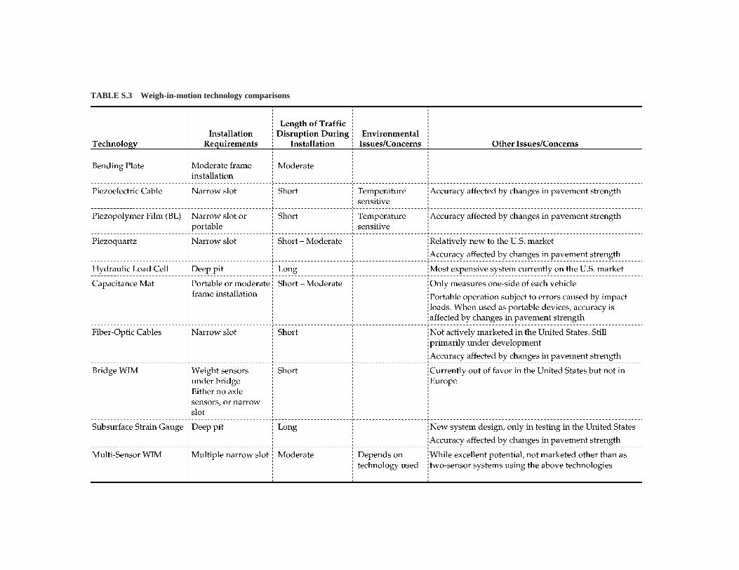
TABLE S.3 Weigh-in-motion technology comparisons
13
that the dynamic effects of the pavement leading to the scale sensor can be accountedfor in the WIM scale calibration.
The need for site-specific calibration means that portable scales must be calibratedeach time they are placed on the road surface. This roughly doubles the cost of settingup a portable weighing session because calibration often takes as much staff time as (ifnot more staff time than) portable sensor placement and pick up. When these calibrationcosts are accounted for, many highway agencies find that portable WIM becomes costprohibitive relative to the use of “short-term permanent” WIM (placing WIM sensorspermanently in the ground, but only collecting data from the sensors periodically formoderately short periods).
S.4.3 Temperature Sensitivity
Some WIM systems are sensitive to temperature. Piezoceramic and piezopolymersensors are both temperature sensitive (i.e., their signal strength for a given axle forcechanges with temperature). While some vendors have developed compensation algo-rithms to account for temperature sensitivity, these technologies are at a disadvantagewhen placed in environments that include quickly changing temperatures.
Because the strength of asphalt pavements also changes as environmental conditionschange, the technologies that rely on direct structural support from the pavement itselfwill perform less consistently in these pavements than at locations where the pave-ment’s strength characteristics will not change (e.g., thicker asphalt and concrete sec-tions). Also more successful will be WIM technologies whose axle sensor support is notaffected by changing environmental conditions.
S.4.4 Scale Sensor Width, Accuracy, and Installation Effects
The larger the size of the scale sensor, the longer a tire is in contact with the sensorand the longer the period during which force is measured. This provides an accuracyadvantage to wider sensors in comparison with narrow sensors. (Note, however, that ifthe scale grows too wide, such as with some bridge WIM installations, multiple vehi-cles will be on the sensor at the same time, thus degrading weighing accuracy.) Verynarrow sensors also permit tires to “bridge” the sensor, meaning that at no point is theentire weight of the tire supported solely by the sensor. This decreases the sensitivityof the sensor and makes weighing accuracy more sensitive to environmental changesin pavement strength.
A significant advantage of narrow strip sensors is that installation is far easier andtakes considerably less time than for wider sensors. As a result, these sensors tend tobe less expensive to install. They also tend to be less expensive per sensor than widersensors.
S.4.5 Number and Location of Sensors
The most common means of reducing inaccuracy in weighing caused by vehicledynamics is to weigh an axle at more than one location as it moves along a road. Increas-ing the number of weight sensors used by a WIM device (when those sensors are placedin series) allows a more complete analysis of vehicle dynamics and, consequently, pro-vides a better estimate of each axle’s static weight. Thus, in general, the larger the num-ber of sensors placed in series on the roadway, the more accurate the system will be. Inaddition, having multiple sensors allows the failure of at least one sensor without the loss
of all WIM capability. Unfortunately, each extra scale sensor increases the cost of theWIM system. Therefore, multi-sensor WIM systems tend to use less expensive, narrowstrip sensors.
Most multi-sensor systems marketed in the United States place two scale sensors inseries in the roadway. However, some vendors of wider bending plate sensors achievea similar weighing-in-series effect by staggering their half-lane sensors (weighing firstone side of the truck, and then the other side of the truck), rather than placing them side-by-side. This, too, measures a greater range of the truck’s dynamic motion, increasingthe scale’s ability to account for vehicle dynamics.
Several European WIM tests have shown that further advances in WIM system accu-racy can be obtained by using even more sensors. To date, the use of three or more sen-sors in series has not been adopted in the United States for production weighing.
S.4.6 Location of the Sensor Relative to the Pavement Surface
Field tests to date have shown that the most accurate WIM systems have sensors thatare mounted flush with the existing road surface. Sensors that sit on top of the pave-ment create their own bump (even a very small bump is bad) that increases vehicledynamics, which in turn decrease sensor accuracy. Sensors that are entirely covered bypavement are affected by changes in pavement strength associated with changes inenvironmental conditions. Changes in pavement profile (such as rut formation) thatdecrease the smoothness of the transition from the pavement surface to the WIM sen-sor surface cause impact loads and increased vehicle dynamics, both of which con-tribute to loss of WIM system accuracy.
S.5 ADDITIONAL GENERAL GUIDANCE
While it is important to select technologies that can operate in the conditions inwhich they are installed, a successful data collection program will also incorporate allof the attributes presented below. Some of these attributes have not been mentioned inthe preceding sections but are explained more fully in the other chapters.
• Make sure that the equipment selected can collect data that meet the users’requirements.
• For permanently placed equipment, match the design life of the equipment to the(remaining) design life of the location (pavement) where it will be installed.
• Make sure that the equipment selected can operate accurately at the location wheredata are required.
• Budget the necessary resources to install, calibrate, operate, and maintain theequipment, including site preventive and corrective maintenance. (Under-fundedprograms often collect poor data because the programs sacrifice quality for quan-tity, thereby collecting “data” that are mostly noise, not information.)
• Develop, use, and maintain a quality assurance program. This includes makingsure that equipment is properly calibrated when first installed, that data producedby that equipment are regularly checked for quality, and that identification of sus-pect data or equipment performance results in an investigation of the cause andeither confirms accurate system performance or results in repairs, replacement, orremoval of the malfunctioning equipment.
• Select equipment that has passed an independent performance test (such as ASTM E 1318) and for which vendors are willing to supply warranties of performance.
14
15
• Make sure that the staff installing the equipment are fully trained in the installationof that equipment and that they understand the factors that affect its performance.
• Maintain a preventive and corrective maintenance program to ensure that data col-lection equipment reaches its expected life and that the data provided are accurate.
S.6 RESOURCES
S.6.1 Paper Reports
American Society of Testing Materials, Annual Book of ASTM Standards 2000, Section 4, Construc-tion, Volume 04.03, Designation: E 1318—Standard Specification for Highway Weigh-In-Motion(WIM) Systems with User Requirements and Test Method.
Middleton, D., Jasek, D., and Parker, R., “Evaluation of Some Existing Technologies for VehicleDetection,” Project Summary Report 1715-S. Texas Transportation Institute, September 1999.
McCall, B., and Vodrazka Jr., W.C., States Successful Practices Weigh-In-Motion Handbook, Cen-ter for Transportation Research and Education (CTRE), Iowa State University, December 15, 1997,http://www.ctre.iastate.edu/research/wim_pdf/index.htm.
Skszek, Sherry, State-of-the-Art Report on Non-Traditional Traffic Counting Methods, Final Report#503, Arizona Department of Transportation, October 2001.
S.6.2 On-Line Resources (accessible as of June 20, 2003)
The Vehicle Detector Clearinghouse at New Mexico State University http://www.nmsu.edu/~traffic/.FHWA’s Demonstration Project 121 web site on Weigh-in-Motion Technology http://www.ornl.
gov/dp121/ maintained by Oak Ridge National Laboratory.The European Weigh-in-Motion of Axles and Vehicles for Europe (WAVE) project web site, http://
wim.zag.si/wave/.The Minnesota Guidestar Non-Intrusive Traffic Detection Tests http://www.dot.state.mn.us/guidestar/
projects/nitd.html.
16
CHAPTER 1
INTRODUCTION
This report is designed to serve as a primer on the selec-tion and use of equipment for counting and classifying vehi-cles and for collecting data on their axle weights. The datacollected by this equipment are specifically required by themechanistic-empirical pavement design procedures beingdeveloped under NCHRP Project 1-37A (Development of the2002 Guide for the Design of New and Rehabilitated Pave-ment Structures). These data are also required by other pro-cedures that incorporate estimates of expected pavementstresses into the design of pavements.
The most important finding of an extensive review of theavailable literature on equipment performance is that widevariation exists in the reported error rates for any given tech-nology. In fact, different results are often reported for dif-ferent tests of a specific device from the same manufacturer.Closer examination of these results almost always leads tothe conclusion that the observed variation is a direct result ofdifferences in the environment in which the devices wereplaced, as well as how well each specific piece of equipmentwas placed, calibrated, maintained, and operated.
When the Minnesota Guidestar program examined non-intrusive sensors,1 one of its primary conclusions was that“the differences between devices from different manufactur-ers were more significant than differences between technolo-gies.” The report also stated, “It is more important to select awell designed and highly reliable product than to narrow aselection to a particular technology.”
Taken together, these observations make it clear that nosingle technology is best and that simply purchasing all datacollection equipment from a reputable vendor will not ensureaccurate data collection. Rather, the following is required:
• A careful examination of equipment capabilities and lim-itations relative to the data collection environment inwhich that equipment will be placed and
• The deployment of a comprehensive data collection pro-gram that includes, at a minimum,– Acceptance testing of purchased equipment;– Staff training in that equipment’s placement, opera-
tion, and maintenance;– Quality assurance tests on the data that are collected;– The funding necessary to purchase and properly install,
inspect, maintain, and operate the equipment; and– Sufficient vendor support to quickly resolve problems
identified as the equipment is used.
This report provides a basic overview of the steps requiredto select the equipment necessary to collect traffic load data.The report also discusses all these data collection programattributes.
The report is organized into a summary and five chapters,including this introduction. Chapter 2 provides a brief intro-duction to the types of equipment available for collectingclassification counts and for weighing vehicles in motion, andChapter 3 contains more detailed descriptions of the varioustechnologies. Chapter 4 provides guidance on the selectionof equipment, and the final chapter offers additional guidanceon the implementation and use of the equipment.
1 Field Test of Monitoring of Urban Vehicle Operations Using Non-Intrusive Technolo-gies, FHWA, May 1997, FHWA-PL-97-018, by Minnesota DOT and SRF Consulting.
17
CHAPTER 2
TYPES OF EQUIPMENT
This chapter presents an introductory summary of the typesof equipment that are available for collecting classificationcounts and for weighing vehicles in motion. For this purpose,the authors categorize equipment by the type of data collected:
• Short-duration portable vehicle classification counts;• Continuous (long-duration) vehicle classification counts;• Short-duration, weigh-in-motion (WIM) data; and• Continuous (long-duration) WIM data.
In addition, the classification technologies are further dif-ferentiated by whether the sensors are placed in or on the road-way surface (intrusive sensors) or whether they are placedabove or beside the roadway (non-intrusive). Vehicle classifi-cation can be performed using either intrusive or non-intrusivesensors, although the style of sensor used affects the dataavailable for classifying vehicles and thus the definition ofvehicle categories into which vehicle counts are placed. On theother hand, current WIM technologies all require on-surface orin-pavement sensors.
2.1 VEHICLE CLASSIFICATION
Vehicles can be classified using any one of several cate-gorization schemes, and alternative schemes often use dif-ferent characteristics to differentiate between vehicles. Themost common classification schemes are based on
• Number and spacing of axles,• Total vehicle length,• Body or trailer type,• Vehicle weight, or• Engine/fuel type.
Most technologies can collect some but not all of these dif-ferent characteristics. Thus, if a specific classification schemeis required, it is important to select a data collection tech-nology that can collect the vehicle characteristics that definethat scheme. Similarly, if a specific technology must be usedbecause of some other constraint (such as environmentalfactors or pavement condition), it is important to understandthe restrictions that the use of that technology places on theclassification scheme. For example, use of two conventional
inductive loops in series (dual loops) allows for classificationbased on overall vehicle length, but does not allow for classi-fication using the FHWA’s 13-category, axle-based scheme.
2.1.1 Short-Duration Classification Counts
Short-duration counts are the most common of all classi-fication counts. Prior to the mid-1980s, classification countswere almost always collected manually by roadside observers.Visual observation allows a wide variety of classificationschemes, including those based on body type and those basedon vehicle configuration and number of axles. However,because manual observation is expensive, highway agencieshave transitioned to automated data collection. Since the mid-1980s, most classification data have been collected usingportable sensors placed on top of the roadway surface. Thischoice of technology means that most classification countsnow use axle- or length-based classification schemes. How-ever, further advancements in technology, as well as limita-tions in the more traditional data collection technologies,have encouraged highway agencies and vendors to experi-ment with portable versions of non-intrusive sensors.
Short-duration classification counts are collected at a widevariety of locations. In addition to collecting accurate data,the technology used for short-duration counts must be easilymoved from location to location, be easy and safe to place,have portable power supplies that can keep the equipmentoperating for the periods desired, and be relatively inexpensive.Short-duration counts are most commonly collected for peri-ods of 24 or 48 hours, although some highway agencies attemptto collect as many as seven consecutive days of such data.
Portable sensors that are commonly used for collectingvehicle classification data include
• Road tubes,• Piezoelectric sensors,• Fiber-optic cable,• Portable inductance loops, and• Magnetometers.
The first three of these types of sensor provide informationsufficient for use when classifying vehicles into the FHWA’s13-category system, but inductance loops and magnetometers
do not. The primary advantages of these three technologiesare that they are relatively inexpensive to purchase, are easyand inexpensive to place, and are capable of providing theinformation required for most uses. The technologies’ biggestdrawback is that they are generally designed to operate in low-and moderate-volume rural settings. In congested conditions,where vehicles are accelerating or decelerating while crossingthe sensors, or where vehicles are tailgating each other, thesesensors often have accuracy problems caused by an inabilityto measure axle spacings correctly or to distinguish betweenclosely spaced vehicles. (For example, in congested condi-tions, two closely spaced cars are often reported incorrectly asa single, four-axle, combination truck.) In addition, on higher-volume roadways, even the most quickly installed sensorsrequire the presence of full traffic control in order to protectthe staff placing the sensors. The need for traffic control sig-nificantly increases the cost of portable data collection andcan entirely prevent short-duration classification data collec-tion where staff are not able to safely place sensors.
Research is currently being performed on the developmentof non-intrusive sensors specifically designed for collectingtruck volume information on high-volume urban roadways.The Minnesota Department of Transportation has recentlybegun testing these devices.
In order to increase staff safety, eliminate the need for traf-fic control for each count, and allow data collection on high-volume roadways, some highway agencies place sensors per-manently in the ground at high-volume locations, but onlycollect data at these locations periodically. In these cases, thedata collection electronics usually “rove” from sensor locationto sensor location. This allows short-duration counts to bemade quickly and inexpensively by simply connecting the rov-ing electronics to existing permanently mounted sensors. Thisoption reduces the cost and danger of placing sensors when-ever counts are required, but it entails a high capital cost forinitial purchase and installation of a large number of sensors.
2.1.2 Continuous Classification Counts
Equipment that works well for short-duration classifica-tion counting often is a poor choice for continuous data col-lection over longer periods of time. Technologies that usesensors mounted on the surface of a roadway usually are notable to operate for extended periods of time without havingthe sensors reinstalled because the traffic has loosened themfrom their original placements. Continuous counts require along-lived sensor installation. In addition, continuous countdevices require power and communications capabilities thatare far different from portable devices. Portable counts nor-mally are collected using battery power, with the counts down-loaded manually from the data collection electronics to a lap-top computer or data transfer device. Long-duration counts,however, require electrical power, usually from electric powerservice or from solar cells, as well as telephone communica-tions for downloading data.
18
As a consequence, data collection efforts at permanentlyplaced, continuous count locations tend to be far more capi-tal intensive than are those of short-duration counts. Contin-uous counts usually use sensors that require traffic controlor heavy equipment (such as a bucket truck and a trenchingmachine) for placement and are made by counting devicesthat are stored in installed, locked cabinets rather than chainedto nearby utility poles. However, once these devices areplaced, they are designed to operate with relatively little staffintervention except for periodic maintenance.
The most common data collection technologies for con-tinuous classification data collection are in-pavement sensorsbased on dual-inductance loops or piezoelectric (ceramic)cables. Limitations in these two technologies, and the recog-nition that more classification data are needed, have led to asignificant increase in the number of technologies availablefor conducting continuous vehicle classification counts. Inparticular, considerable advances have been made in the devel-opment of non-intrusive technologies, which use sensors thatare not physically placed in the roadway itself but which mon-itor traffic from above or beside the road. Non-intrusive sen-sors have the advantage of allowing sensor placement with nolane closure (for roadside sensors) or with a less disruptiveclosure (for overhead-mounted sensors). They also have theadvantage of not being subject to the impact of traffic loadsor to the stresses that result from pavement interaction withthe environment.
However, non-intrusive sensors have limitations. The fore-most limitation is that it is more difficult to detect and countthe axles on passing vehicles with non-intrusive sensors thanwith intrusive sensors such as the piezo cable. Because axlecounts by type of axle are generally required for accuratelyestimating pavement loads, data collected with non-intrusivesensors usually require at least one extra data manipulationstep (based on assumptions) when used for pavement loaddetermination. This step involves converting the vehicleclasses collected with the non-intrusive technologies into avehicle classification scheme compatible with the vehicleclasses that are collected using available WIM technologies.
Finally, even the newest technologies have difficulty cor-rectly classifying vehicles in stop-and-go traffic and whenvehicle separation is small. These conditions make it extremelydifficult to separate tailgating cars from multi-unit trucks andmake it very difficult to measure vehicle length and axle spac-ing correctly. These limitations are a primary reason why moststates have only modest amounts of classification data forurban roadways.
2.2 WIM DATA
2.2.1 Short-Duration WIM
Two technologies, capacitance mats and BL-style piezo-electric sensors, are commonly used in the United States forhigh-speed (i.e., on-highway) portable WIM data collection.
Both technologies involve mounting a sensor on top of exist-ing pavement. This action requires a temporary lane closureand often work by more than one person.
While the basic technique of placing sensors on top of theroadway is essential for collecting WIM data in a truly portablemode (i.e., at any site that meets the physical requirements foracceptable sensor operation), there is a system performanceproblem that limits the accuracy of high-speed portable WIMscales.
Because the sensor is physically on top of the roadway sur-face, a bump is created as the tire of each axle mounts theweight sensor. This bump causes two physical effects, eachof which is detrimental to WIM system accuracy. The firsteffect is the additional dynamic motion imparted on the vehi-cle being weighed. This motion makes it much harder for theWIM system to accurately estimate the static weight appliedby each axle. The second physical effect is that the need toclimb over this bump causes the tire itself to flex, absorbingsome of the horizontal force from impact with the bump. Thistire flex force is transmitted to the weight sensor, causing addi-tional bias and noise in the measurement process.
The result of these physical phenomena is that portableWIM rarely achieves the same level of accuracy as a correctlyplaced permanent scale. This does not mean that weights col-lected using portable scales are not useful in the traffic loadestimation process, but it does mean that highway agenciesmust be particularly careful to calibrate portable scales eachtime they are placed on the roadway and to monitor the dataproduced after scales have been calibrated to ensure that thesystem is producing reliable results.
The need to calibrate every time portable sensors are placedalso reduces the difference in the total costs associated withdata collection using permanently mounted sensors and usingportable sensors. Without calibration, data collected by por-table scales will be significantly less accurate than data pro-duced by permanent scales.
Because of the limitations in truly portable WIM systems,some state highway agencies use one of two methods for col-lecting short-duration WIM data. One method involves theuse of low-speed (off-highway) WIM scales or portable static scales. The other method relies on permanently mountedweight sensors and portable data collection electronics.
In the first method, conventional, portable static scales(loadometers) or low-speed portable WIM scales (usuallybending plates or capacitance pads) are used for portableweight data collection. These traditional technologies requireflat areas (such as a parking area of a rest stop) where thescales can be laid out and trucks diverted over the scales.Trucks are either stopped on these scales or driven at slowspeeds over the scales. These data collection techniques tendto be labor intensive (because trucks must be directed overthe scales), and they result in fairly small datasets in com-parison with high-speed WIM data collection. Also, they dis-rupt the truck traffic stream (which must be diverted off theroadway and over the scales), and drivers are likely to assume
19
they are being used for weight enforcement. Hence, these col-lection locations may be avoided by illegally overloadedtrucks, resulting in biased results. However, these technologiesare acceptable for truck weight data collection where truckvolumes are light, where only a small sample is required, andwhere truck evasion is difficult because of limited opportu-nity for trucks to by-pass the scale site.
The second method uses portable electronics with perma-nently mounted WIM sensors that allow weight sensors to beflush mounted with the roadway. This eliminates the bumpthat occurs with surface-mounted sensors and results in a bet-ter environment for collecting accurate axle weights, but itdoes not ensure accurate WIM data. Even in this type of por-table operation, calibration is required prior to starting datacollection, and care should be taken to ensure that pavementdeterioration over time has not created bumps at the jointbetween sensors and roadways. This type of site is less costlyto operate than a continuously operated WIM site (becauseone set of data collection electronics is used for several datacollection sites and because permanent power and commu-nications are not needed and therefore do not need to be con-structed). However, the initial capital cost is higher than fortruly portable WIM—a factor that the highway agency con-siders when deciding where to collect WIM data.
2.2.2 Continuous WIM
Because of the physics problem noted above for portableequipment, the majority of research and development in WIMhas been done for permanently installed weight sensors. Fivetechnologies are currently in common use throughout theUnited States. Other sensor designs are under active develop-ment. The most common permanently mounted weight sen-sors are
• Bending plates,• Hydraulic load cells,• Piezoceramic cables,• Piezopolymer cables, and• Piezoquartz sensors.
Other sensor technologies that are either in more limiteduse or are still under development include
• Permanently mounted capacitance mats,• Permanently mounted capacitance strips,• Fiber-optic cables,• Subsurface strain-gauge frame, and• Bridge or culvert WIM.
All of the systems are designed to have sensors perma-nently installed in or under the roadway. This results in lessdynamic vehicle motion and less impact force on sensors thanfor surface-mounted sensors, which in turn results in moreaccurate weighing conditions and longer sensor life.
The various sensor technologies were developed either totake advantage of particular material properties (to reducethe cost of the sensor and/or installation) or to provide a spe-cific advantage to the signal-processing algorithm that con-verts sensor output into an estimate of axle weight. Each sen-sor technology has its own strengths and weaknesses. No onesensor is best for every WIM application.
For example, both the piezoelectric cable and fiber-opticcable sensors are specifically designed to require a relativelysmall pavement cut for sensor installation. This results in afast and relatively low-cost sensor installation. However, thesesensors are so small that at no time during the weighingprocess is the entire tire (axle) that is being weighed isolatedon the sensor. Thus, both of these technologies suffer fromsignal noise because of the fact that, during the weighingprocess, the axle weight is partially supported by the pave-ment that surrounds the sensor.
Each vendor takes into account the selected sensor’sstrengths and weaknesses when designing a WIM system. Themeans for accounting for specific weaknesses has a great dealto do with how well specific sensors work in given installa-tions. Because vendors often take different approaches tosensor installation design and signal processing, the perfor-mance of a specific sensor technology can vary widely fromvendor to vendor. In some cases, the conditions at a specificWIM site directly (and negatively) coincide with the partic-ular weakness of a given sensor technology. In these cases,even the best vendor responses to handling those weaknessesmay not allow sensors to work correctly.
A good example is temperature sensitivity. Temperature-sensitive WIM sensors are not good choices for WIM siteswhere temperatures change rapidly. Although such sensors areused with temperature compensation algorithms, often basedon some type of autocalibration technique, these adjustmentscannot be made fast enough to maintain scale accuracy in
20
areas with rapid temperature changes, such as those experi-enced in mountain passes and in the Southwestern deserts.
Environmental and site conditions (pavement condition,temperature, wind, grades, etc.) play a large role in the per-formance of any WIM system, regardless of sensor technol-ogy. A high-speed WIM system will not work accurately ifthe site selected for weighing is not conducive to weight datacollection. ASTM specification E 13181 provides specificguidance on the pavement conditions needed for accurateWIM system performance. This guidance stipulates a pave-ment that is
• Flat (no horizontal or vertical curves),• Smooth (no bumps or other surface conditions that cre-
ate vehicle dynamics),• Strong (to reduce pavement flex underneath the WIM
sensor), and• In good condition.
WIM sites should also be sites where vehicles are travel-ing at fairly constant speeds (i.e., not accelerating or decel-erating), are not changing lanes frequently, and have goodlane discipline. If these conditions are met, then the trucksbeing weighed are likely to have relatively modest dynamicmotion. They will tend to track correctly in their lanes (andwill hit the weight sensors as expected), and the speeds mea-sured and used in various signal-processing algorithms willbe accurate. All of these factors improve the performance ofany WIM system, regardless of sensor technology.
1 American Society of Testing Materials, Annual Book of ASTM Standards 2000, Sec-tion 4, Construction, Volume 04.03, Designation: E 1318—Standard Specification forHighway Weigh-In-Motion (WIM) Systems with User Requirements and Test Method,ASTM, 100 Barr Harbor Drive, West Conshohocken, Pennsylvania, 19428-2959.
21
CHAPTER 3
TECHNOLOGY DESCRIPTIONS
Tables 3.1 and 3.2 list the most commonly used technolo-gies for vehicle classification and WIM, respectively, togetherwith their primary strengths and related concerns. Strengthsand concerns are summaries of material found in the literature.Opinions of the strengths, weaknesses, or level of expectedperformance for any given technology or piece of equipmentoften differ from one expert to another, usually based on theexperience that individual has had with a specific piece ofequipment. The performance of any specific device may differfrom these summaries. This chapter provides further informa-tion about
• How these technologies work,• The types of data they can provide,• Installation conditions required for accurate performance,• Specific weaknesses, and• Typical uses (e.g., portable versus permanent data col-
lection).
As noted earlier, sensor technology is constantly underdevelopment. This chapter includes summaries of publishedresearch. For more current information, readers should consultresources such as the Vehicle Detector Clearinghouse at NewMexico State University (http://www.nmsu.edu/~traffic/),the FHWA’s Demonstration Project 121 web site on WIMTechnology (http://www.ornl.gov/dp121/) maintained by OakRidge National Laboratories, and the European WIM of Axlesand Vehicles for Europe (WAVE) project web site (http://wim.zag.si/wave/).1 In addition, excellent written documen-tation exists that should be used when learning about equip-ment attributes and selection. Useful documents include theFHWA’s States Successful Practices WIM Handbook,2 theTraffic Detector Handbook,3 the FHWA’s Traffic MonitoringGuide,4 and the ASTM E 1318 WIM5 standard. This report
should serve primarily as a starting point to the selection andoperation of vehicle classification and WIM equipment.
3.1 VEHICLE CLASSIFICATION
The descriptions of technologies for vehicle classificationare grouped on the basis of whether they use intrusive ornon-intrusive sensors. Technologies using temporary, sur-face-mounted sensors are considered intrusive technologies,because they involve access to the roadway structure.
3.1.1 Intrusive Technologies
This section covers sensor technologies that are placed eitherin or on top of the pavement and, at a minimum, provide theability to classify vehicles into passenger vehicles and trucks.
Portable Operations
Portable sensor technologies used for classification include
• Road tubes,• Piezoelectric sensors (BL [brass linguini], ceramic cable,
and quartz),• Fiber-optic cable,• Other pressure sensors,• Preformed inductance loops,• Magnetometers, and• Side-fired radar and other non-intrusive sensors.
Road tubes, piezoelectric sensors, and fiber-optic cabletechnologies are pressure sensitive. That is, they deflect asvehicle tires pass over them, and the deflection causes a sig-nal that is detected and interpreted. Inductance loop and mag-netometer technologies are presence detectors that detect thepresence of a vehicle (by changes in the sensor’s inductanceor the earth’s magnetic field) as a result of the presence ofmetal in the vehicle.
Pressure-sensitive technologies have several strengths andweaknesses. These technologies count vehicle axles and mea-sure axle spacings. Most classification systems that use intru-sive sensors base their classification on these variables. Hence,the performance of the equipment is a function of how accu-rately these measurements are made and how well they assign
1 All web sites referenced in this report were active as of June 20, 2003.2 B. McCall and W.C. Vodrazka Jr., States Successful Practices WIM Handbook, Cen-
ter for Transportation Research and Education (CTRE), Iowa State University, Decem-ber 15, 1997, http://www.ctre.iastate.edu/research/wim_pdf/index.htm.
3 J.H. Kell and I.J. Fullerton, Traffic Detector Handbook, Second Edition, U.S. Depart-ment of Transportation, Federal Highway Administration, Washington, D.C., 1992.
4 Traffic Monitoring Guide, U.S. Department of Transportation, Federal HighwayAdministration, Office of Highway Policy, January 2001, http://www.fhwa.dot.gov/ohim/tmguide/index.htm.
5 American Society of Testing Materials, Annual Book of ASTM Standards 2000, Sec-tion 4, Construction, Volume 04.03, Designation: E 1318-02—Standard Specificationfor Highway WIM (WIM) Systems with User Requirements and Test Method.
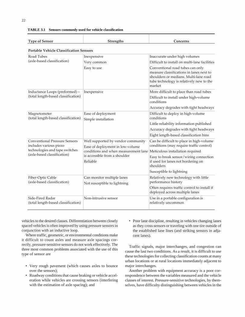
vehicles to the desired classes. Differentiation between closelyspaced vehicles is often improved by using pressure sensors inconjunction with an inductive loop.
Where traffic, geometric, or environmental conditions makeit difficult to count axles and measure axle spacings cor-rectly, pressure-sensitive sensors do not work effectively. Thethree most common problems associated with the use of thistype of sensor are
• Very rough pavement (which causes axles to bounceover the sensors);
• Roadway conditions that cause braking or vehicle accel-eration while vehicles are crossing sensors (interferingwith the estimation of axle spacing); and
22
• Poor lane discipline, resulting in vehicles changing lanesas they cross sensors or traveling with one tire outside ofthe established lane lines (and striking sensors in adja-cent lanes).
Traffic signals, major interchanges, and congestion cancause the last two conditions. As a result, it is difficult to usethese technologies for collecting classification counts at manyurban locations or at rural locations immediately adjacent tomajor interchanges.
Another problem with equipment accuracy is a poor cor-respondence between the variables measured and the vehicleclasses of interest. Pressure-sensitive technologies, by them-selves, have difficulty distinguishing between vehicles in the
Type of Sensor Strengths Concerns
Portable Vehicle Classification Sensors
Road Tubes (axle-based classification)
Inexpensive
Very common
Easy to use
Inaccurate under high volumes
Difficult to install on multi-lane facilities
Conventional road tubes can only measure classifications in lanes next to shoulders or medians. Multi-lane road tube technology is relatively new to the market
Inductance Loops (preformed) – (total length-based classification)
Inexpensive More difficult to place than road tubes
Difficult to install under high-volume conditions
Accuracy degrades with tight headways
Magnetometer (total length-based classification)
Ease of deployment
Simple installation
Difficult to deploy in high-volume conditions
Little reliability information published
Accuracy degrades with tight headways
Eight length-based classification bins
Conventional Pressure Sensors includes various piezo technologies and tape switches (axle-based classification)
Well supported by vendor community
Ease of deployment in low-volume conditions and when measurement lane is accessible from a shoulder
Reliable
Can be difficult to place in high-volume conditions (may require traffic control)
Meticulous installation required
Easy to break sensor/wiring connection if used for lanes not bordering on shoulders
Susceptible to lightning
Fiber-Optic Cable (axle-based classification)
Can monitor multiple lanes
Not susceptible to lightning
Relatively new technology with little performance history
Often requires traffic control to install if deployed across multiple lanes
Side-Fired Radar (total length-based classification)
Non-intrusive sensor Use in a portable configuration is relatively uncommon
TABLE 3.1 Sensors commonly used for vehicle classification
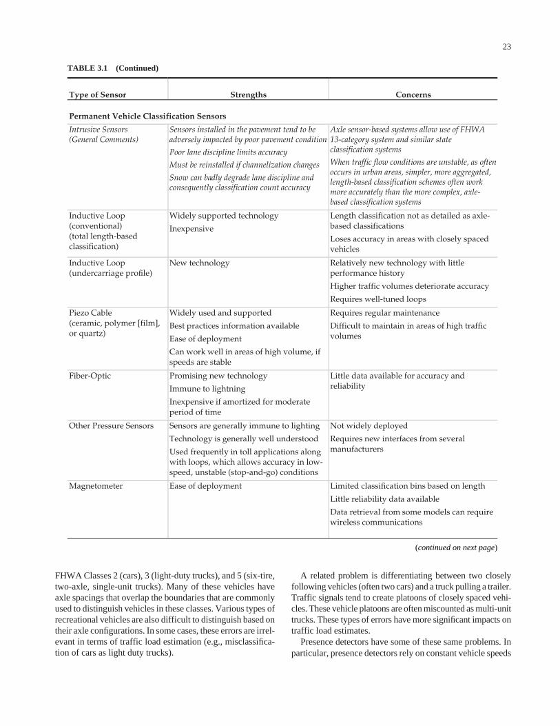
FHWA Classes 2 (cars), 3 (light-duty trucks), and 5 (six-tire,two-axle, single-unit trucks). Many of these vehicles haveaxle spacings that overlap the boundaries that are commonlyused to distinguish vehicles in these classes. Various types ofrecreational vehicles are also difficult to distinguish based ontheir axle configurations. In some cases, these errors are irrel-evant in terms of traffic load estimation (e.g., misclassifica-tion of cars as light duty trucks).
23
A related problem is differentiating between two closelyfollowing vehicles (often two cars) and a truck pulling a trailer.Traffic signals tend to create platoons of closely spaced vehi-cles. These vehicle platoons are often miscounted as multi-unittrucks. These types of errors have more significant impacts ontraffic load estimates.
Presence detectors have some of these same problems. Inparticular, presence detectors rely on constant vehicle speeds
TABLE 3.1 (Continued)
Type of Sensor Strengths Concerns
Permanent Vehicle Classification Sensors
Intrusive Sensors (General Comments)
Sensors installed in the pavement tend to be adversely impacted by poor pavement condition
Poor lane discipline limits accuracy
Must be reinstalled if channelization changes
Snow can badly degrade lane discipline and consequently classification count accuracy
Axle sensor-based systems allow use of FHWA 13-category system and similar state classification systems
When traffic flow conditions are unstable, as often occurs in urban areas, simpler, more aggregated, length-based classification schemes often work more accurately than the more complex, axle-based classification systems
Inductive Loop (conventional) (total length-based classification)
Widely supported technology
Inexpensive
Length classification not as detailed as axle-based classifications
Loses accuracy in areas with closely spaced vehicles
Inductive Loop (undercarriage profile)
New technology Relatively new technology with little performance history
Higher traffic volumes deteriorate accuracy
Requires well-tuned loops
Piezo Cable (ceramic, polymer [film], or quartz)
Widely used and supported
Best practices information available
Ease of deployment
Can work well in areas of high volume, if speeds are stable
Requires regular maintenance
Difficult to maintain in areas of high traffic volumes
Fiber-Optic Promising new technology
Immune to lightning
Inexpensive if amortized for moderate period of time
Little data available for accuracy and reliability
Other Pressure Sensors Sensors are generally immune to lighting
Technology is generally well understood
Used frequently in toll applications along with loops, which allows accuracy in low-speed, unstable (stop-and-go) conditions
Not widely deployed
Requires new interfaces from several manufacturers
Magnetometer Ease of deployment
Limited classification bins based on length
Little reliability data available
Data retrieval from some models can require wireless communications
(continued on next page)
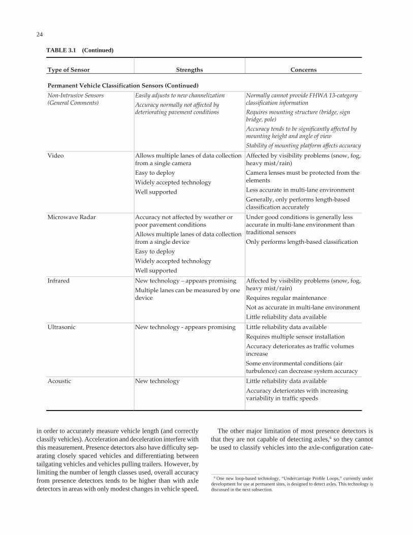
in order to accurately measure vehicle length (and correctlyclassify vehicles). Acceleration and deceleration interfere withthis measurement. Presence detectors also have difficulty sep-arating closely spaced vehicles and differentiating betweentailgating vehicles and vehicles pulling trailers. However, bylimiting the number of length classes used, overall accuracyfrom presence detectors tends to be higher than with axledetectors in areas with only modest changes in vehicle speed.
24
The other major limitation of most presence detectors isthat they are not capable of detecting axles,6 so they cannotbe used to classify vehicles into the axle-configuration cate-
6 One new loop-based technology, “Undercarriage Profile Loops,” currently underdevelopment for use at permanent sites, is designed to detect axles. This technology isdiscussed in the next subsection.
TABLE 3.1 (Continued)
Type of Sensor Strengths Concerns
Permanent Vehicle Classification Sensors (Continued)
Non-Intrusive Sensors (General Comments)
Easily adjusts to new channelization
Accuracy normally not affected by deteriorating pavement conditions
Normally cannot provide FHWA 13-category classification information
Requires mounting structure (bridge, sign bridge, pole)
Accuracy tends to be significantly affected by mounting height and angle of view
Stability of mounting platform affects accuracy
Video Allows multiple lanes of data collection from a single camera
Easy to deploy
Widely accepted technology
Well supported
Affected by visibility problems (snow, fog, heavy mist/rain)
Camera lenses must be protected from the elements
Less accurate in multi-lane environment
Generally, only performs length-based classification accurately
Microwave Radar Accuracy not affected by weather or poor pavement conditions
Allows multiple lanes of data collection from a single device
Easy to deploy
Widely accepted technology
Well supported
Under good conditions is generally less accurate in multi-lane environment than traditional sensors
Only performs length-based classification
Infrared New technology – appears promising
Multiple lanes can be measured by one device
Affected by visibility problems (snow, fog, heavy mist/rain)
Requires regular maintenance
Not as accurate in multi-lane environment
Little reliability data available
Ultrasonic New technology - appears promising Little reliability data available
Requires multiple sensor installation
Accuracy deteriorates as traffic volumes increase
Some environmental conditions (air turbulence) can decrease system accuracy
Acoustic New technology
Little reliability data available
Accuracy deteriorates with increasing variability in traffic speeds
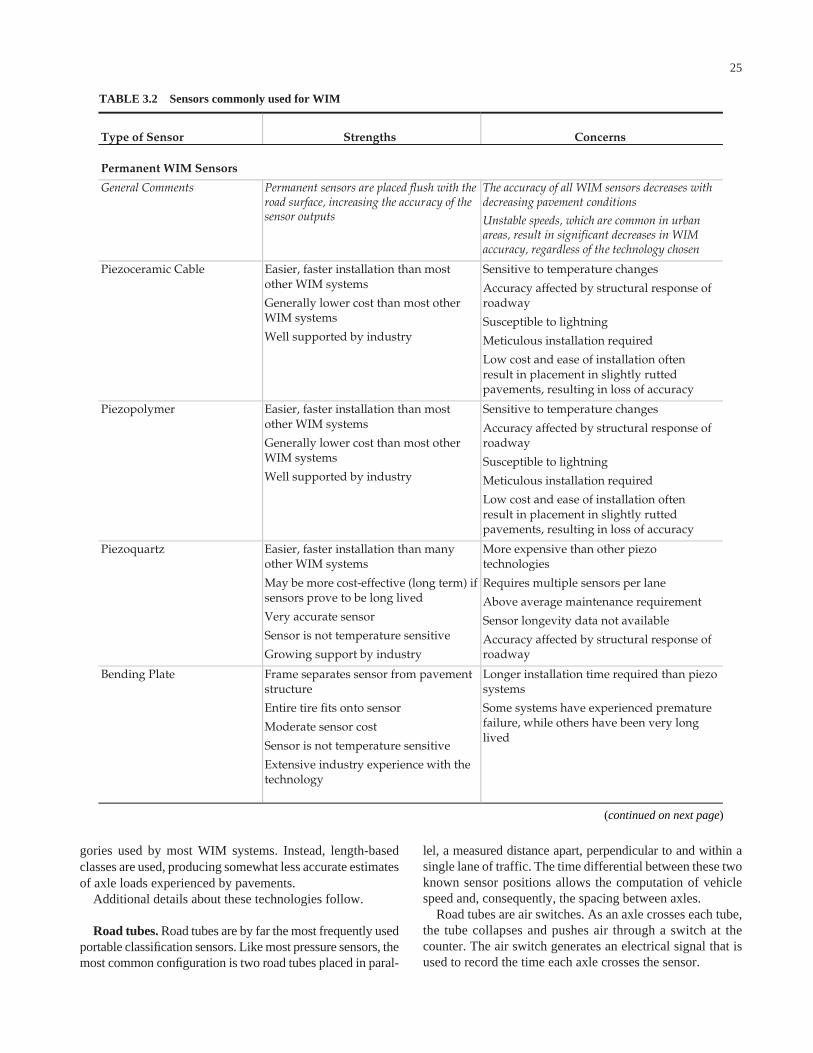
gories used by most WIM systems. Instead, length-basedclasses are used, producing somewhat less accurate estimatesof axle loads experienced by pavements.
Additional details about these technologies follow.
Road tubes. Road tubes are by far the most frequently usedportable classification sensors. Like most pressure sensors, themost common configuration is two road tubes placed in paral-
25
lel, a measured distance apart, perpendicular to and within asingle lane of traffic. The time differential between these twoknown sensor positions allows the computation of vehiclespeed and, consequently, the spacing between axles.
Road tubes are air switches. As an axle crosses each tube,the tube collapses and pushes air through a switch at thecounter. The air switch generates an electrical signal that isused to record the time each axle crosses the sensor.
TABLE 3.2 Sensors commonly used for WIM
Type of Sensor Strengths Concerns
Permanent WIM Sensors
General Comments Permanent sensors are placed flush with the road surface, increasing the accuracy of the sensor outputs
The accuracy of all WIM sensors decreases with decreasing pavement conditions
Unstable speeds, which are common in urban areas, result in significant decreases in WIM accuracy, regardless of the technology chosen
Piezoceramic Cable Easier, faster installation than most other WIM systems
Generally lower cost than most other WIM systems
Well supported by industry
Sensitive to temperature changes
Accuracy affected by structural response of roadway
Susceptible to lightning
Meticulous installation required
Low cost and ease of installation often result in placement in slightly rutted pavements, resulting in loss of accuracy
Piezopolymer Easier, faster installation than most other WIM systems
Generally lower cost than most other WIM systems
Well supported by industry
Sensitive to temperature changes
Accuracy affected by structural response of roadway
Susceptible to lightning
Meticulous installation required
Low cost and ease of installation often result in placement in slightly rutted pavements, resulting in loss of accuracy
Piezoquartz Easier, faster installation than many other WIM systems
May be more cost-effective (long term) if sensors prove to be long lived
Very accurate sensor
Sensor is not temperature sensitive
Growing support by industry
More expensive than other piezo technologies
Requires multiple sensors per lane
Above average maintenance requirement
Sensor longevity data not available
Accuracy affected by structural response of roadway
Bending Plate Frame separates sensor from pavement structure
Entire tire fits onto sensor
Moderate sensor cost
Sensor is not temperature sensitive
Extensive industry experience with the technology
Longer installation time required than piezo systems
Some systems have experienced premature failure, while others have been very long lived
(continued on next page)
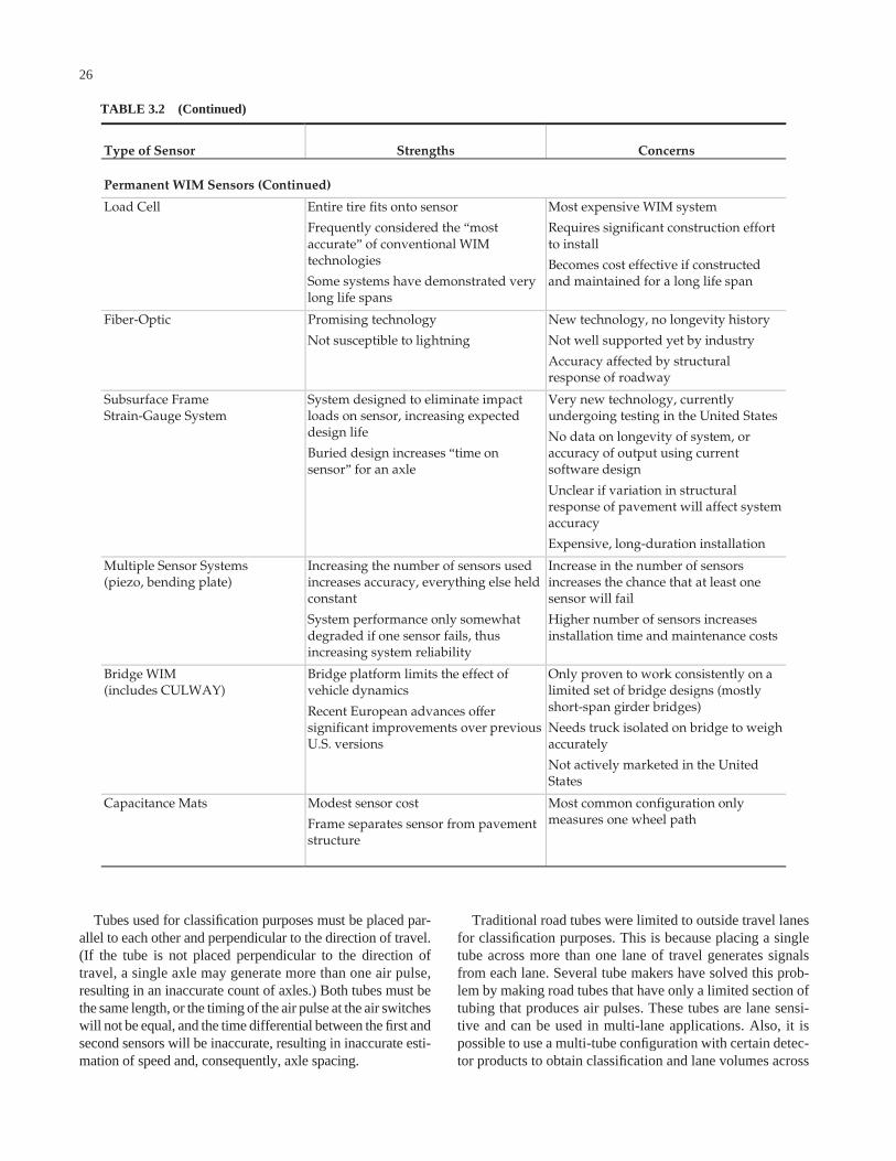
Tubes used for classification purposes must be placed par-allel to each other and perpendicular to the direction of travel.(If the tube is not placed perpendicular to the direction oftravel, a single axle may generate more than one air pulse,resulting in an inaccurate count of axles.) Both tubes must bethe same length, or the timing of the air pulse at the air switcheswill not be equal, and the time differential between the first andsecond sensors will be inaccurate, resulting in inaccurate esti-mation of speed and, consequently, axle spacing.
26
Traditional road tubes were limited to outside travel lanesfor classification purposes. This is because placing a singletube across more than one lane of travel generates signalsfrom each lane. Several tube makers have solved this prob-lem by making road tubes that have only a limited section oftubing that produces air pulses. These tubes are lane sensi-tive and can be used in multi-lane applications. Also, it ispossible to use a multi-tube configuration with certain detec-tor products to obtain classification and lane volumes across
TABLE 3.2 (Continued)
Type of Sensor Strengths Concerns
Permanent WIM Sensors (Continued)
Load Cell Entire tire fits onto sensor
Frequently considered the “most accurate” of conventional WIM technologies
Some systems have demonstrated very long life spans
Most expensive WIM system
Requires significant construction effort to install
Becomes cost effective if constructed and maintained for a long life span
Fiber-Optic Promising technology
Not susceptible to lightning
New technology, no longevity history
Not well supported yet by industry
Accuracy affected by structural response of roadway
Subsurface Frame Strain-Gauge System
System designed to eliminate impact loads on sensor, increasing expected design life
Buried design increases “time on sensor” for an axle
Very new technology, currently undergoing testing in the United States
No data on longevity of system, or accuracy of output using current software design
Unclear if variation in structural response of pavement will affect system accuracy
Expensive, long-duration installation
Multiple Sensor Systems (piezo, bending plate)
Increasing the number of sensors used increases accuracy, everything else held constant
System performance only somewhat degraded if one sensor fails, thus increasing system reliability
Increase in the number of sensors increases the chance that at least one sensor will fail
Higher number of sensors increases installation time and maintenance costs
Bridge WIM (includes CULWAY)
Bridge platform limits the effect of vehicle dynamics
Recent European advances offer significant improvements over previous U.S. versions
Only proven to work consistently on a limited set of bridge designs (mostly short-span girder bridges)
Needs truck isolated on bridge to weigh accurately
Not actively marketed in the United States
Capacitance Mats Modest sensor cost
Frame separates sensor from pavement structure
Most common configuration only measures one wheel path
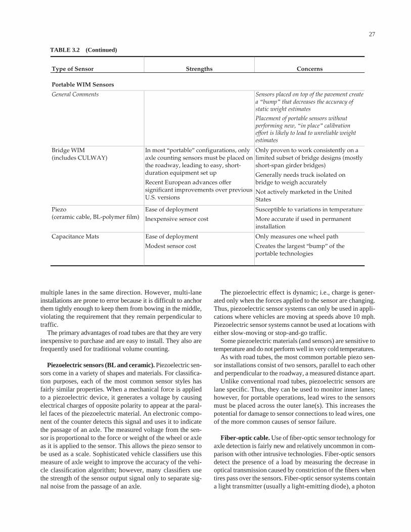
multiple lanes in the same direction. However, multi-laneinstallations are prone to error because it is difficult to anchorthem tightly enough to keep them from bowing in the middle,violating the requirement that they remain perpendicular totraffic.
The primary advantages of road tubes are that they are veryinexpensive to purchase and are easy to install. They also arefrequently used for traditional volume counting.
Piezoelectric sensors (BL and ceramic). Piezoelectric sen-sors come in a variety of shapes and materials. For classifica-tion purposes, each of the most common sensor styles hasfairly similar properties. When a mechanical force is appliedto a piezoelectric device, it generates a voltage by causingelectrical charges of opposite polarity to appear at the paral-lel faces of the piezoelectric material. An electronic compo-nent of the counter detects this signal and uses it to indicatethe passage of an axle. The measured voltage from the sen-sor is proportional to the force or weight of the wheel or axleas it is applied to the sensor. This allows the piezo sensor tobe used as a scale. Sophisticated vehicle classifiers use thismeasure of axle weight to improve the accuracy of the vehi-cle classification algorithm; however, many classifiers usethe strength of the sensor output signal only to separate sig-nal noise from the passage of an axle.
27
The piezoelectric effect is dynamic; i.e., charge is gener-ated only when the forces applied to the sensor are changing.Thus, piezoelectric sensor systems can only be used in appli-cations where vehicles are moving at speeds above 10 mph.Piezoelectric sensor systems cannot be used at locations witheither slow-moving or stop-and-go traffic.
Some piezoelectric materials (and sensors) are sensitive totemperature and do not perform well in very cold temperatures.
As with road tubes, the most common portable piezo sen-sor installations consist of two sensors, parallel to each otherand perpendicular to the roadway, a measured distance apart.
Unlike conventional road tubes, piezoelectric sensors arelane specific. Thus, they can be used to monitor inner lanes;however, for portable operations, lead wires to the sensorsmust be placed across the outer lane(s). This increases thepotential for damage to sensor connections to lead wires, oneof the more common causes of sensor failure.
Fiber-optic cable. Use of fiber-optic sensor technology foraxle detection is fairly new and relatively uncommon in com-parison with other intrusive technologies. Fiber-optic sensorsdetect the presence of a load by measuring the decrease inoptical transmission caused by constriction of the fibers whentires pass over the sensors. Fiber-optic sensor systems containa light transmitter (usually a light-emitting diode), a photon
TABLE 3.2 (Continued)
Type of Sensor Strengths Concerns
Portable WIM Sensors
General Comments Sensors placed on top of the pavement create a “bump” that decreases the accuracy of static weight estimates
Placement of portable sensors without performing new, “in place” calibration effort is likely to lead to unreliable weight estimates
Bridge WIM (includes CULWAY)
In most “portable” configurations, only axle counting sensors must be placed on the roadway, leading to easy, short-duration equipment set up
Recent European advances offer significant improvements over previous U.S. versions
Only proven to work consistently on a limited subset of bridge designs (mostly short-span girder bridges)
Generally needs truck isolated on bridge to weigh accurately
Not actively marketed in the United States
Piezo (ceramic cable, BL-polymer film)
Ease of deployment
Inexpensive sensor cost
Susceptible to variations in temperature
More accurate if used in permanent installation
Capacitance Mats Ease of deployment
Modest sensor cost
Only measures one wheel path
Creates the largest “bump” of the portable technologies
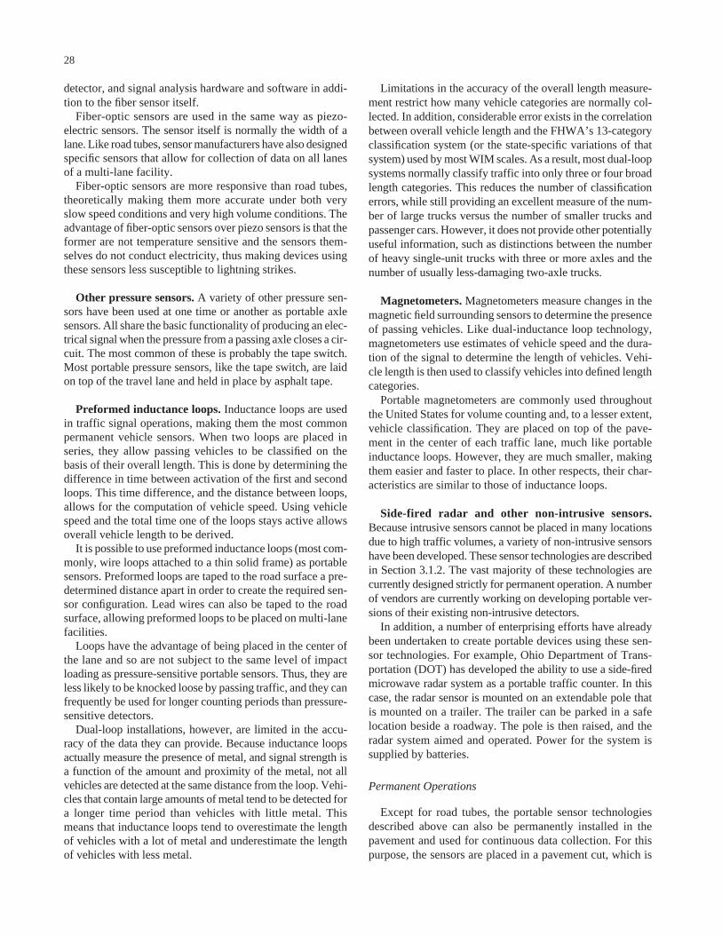
detector, and signal analysis hardware and software in addi-tion to the fiber sensor itself.
Fiber-optic sensors are used in the same way as piezo-electric sensors. The sensor itself is normally the width of alane. Like road tubes, sensor manufacturers have also designedspecific sensors that allow for collection of data on all lanesof a multi-lane facility.
Fiber-optic sensors are more responsive than road tubes,theoretically making them more accurate under both veryslow speed conditions and very high volume conditions. Theadvantage of fiber-optic sensors over piezo sensors is that theformer are not temperature sensitive and the sensors them-selves do not conduct electricity, thus making devices usingthese sensors less susceptible to lightning strikes.
Other pressure sensors. A variety of other pressure sen-sors have been used at one time or another as portable axlesensors. All share the basic functionality of producing an elec-trical signal when the pressure from a passing axle closes a cir-cuit. The most common of these is probably the tape switch.Most portable pressure sensors, like the tape switch, are laidon top of the travel lane and held in place by asphalt tape.
Preformed inductance loops. Inductance loops are usedin traffic signal operations, making them the most commonpermanent vehicle sensors. When two loops are placed inseries, they allow passing vehicles to be classified on thebasis of their overall length. This is done by determining thedifference in time between activation of the first and secondloops. This time difference, and the distance between loops,allows for the computation of vehicle speed. Using vehiclespeed and the total time one of the loops stays active allowsoverall vehicle length to be derived.
It is possible to use preformed inductance loops (most com-monly, wire loops attached to a thin solid frame) as portablesensors. Preformed loops are taped to the road surface a pre-determined distance apart in order to create the required sen-sor configuration. Lead wires can also be taped to the roadsurface, allowing preformed loops to be placed on multi-lanefacilities.
Loops have the advantage of being placed in the center ofthe lane and so are not subject to the same level of impactloading as pressure-sensitive portable sensors. Thus, they areless likely to be knocked loose by passing traffic, and they canfrequently be used for longer counting periods than pressure-sensitive detectors.
Dual-loop installations, however, are limited in the accu-racy of the data they can provide. Because inductance loopsactually measure the presence of metal, and signal strength isa function of the amount and proximity of the metal, not allvehicles are detected at the same distance from the loop. Vehi-cles that contain large amounts of metal tend to be detected fora longer time period than vehicles with little metal. Thismeans that inductance loops tend to overestimate the lengthof vehicles with a lot of metal and underestimate the lengthof vehicles with less metal.
28
Limitations in the accuracy of the overall length measure-ment restrict how many vehicle categories are normally col-lected. In addition, considerable error exists in the correlationbetween overall vehicle length and the FHWA’s 13-categoryclassification system (or the state-specific variations of thatsystem) used by most WIM scales. As a result, most dual-loopsystems normally classify traffic into only three or four broadlength categories. This reduces the number of classificationerrors, while still providing an excellent measure of the num-ber of large trucks versus the number of smaller trucks andpassenger cars. However, it does not provide other potentiallyuseful information, such as distinctions between the numberof heavy single-unit trucks with three or more axles and thenumber of usually less-damaging two-axle trucks.
Magnetometers. Magnetometers measure changes in themagnetic field surrounding sensors to determine the presenceof passing vehicles. Like dual-inductance loop technology,magnetometers use estimates of vehicle speed and the dura-tion of the signal to determine the length of vehicles. Vehi-cle length is then used to classify vehicles into defined lengthcategories.
Portable magnetometers are commonly used throughoutthe United States for volume counting and, to a lesser extent,vehicle classification. They are placed on top of the pave-ment in the center of each traffic lane, much like portableinductance loops. However, they are much smaller, makingthem easier and faster to place. In other respects, their char-acteristics are similar to those of inductance loops.
Side-fired radar and other non-intrusive sensors.Because intrusive sensors cannot be placed in many locationsdue to high traffic volumes, a variety of non-intrusive sensorshave been developed. These sensor technologies are describedin Section 3.1.2. The vast majority of these technologies arecurrently designed strictly for permanent operation. A numberof vendors are currently working on developing portable ver-sions of their existing non-intrusive detectors.
In addition, a number of enterprising efforts have alreadybeen undertaken to create portable devices using these sen-sor technologies. For example, Ohio Department of Trans-portation (DOT) has developed the ability to use a side-firedmicrowave radar system as a portable traffic counter. In thiscase, the radar sensor is mounted on an extendable pole thatis mounted on a trailer. The trailer can be parked in a safelocation beside a roadway. The pole is then raised, and theradar system aimed and operated. Power for the system issupplied by batteries.
Permanent Operations
Except for road tubes, the portable sensor technologiesdescribed above can also be permanently installed in thepavement and used for continuous data collection. For thispurpose, the sensors are placed in a pavement cut, which is
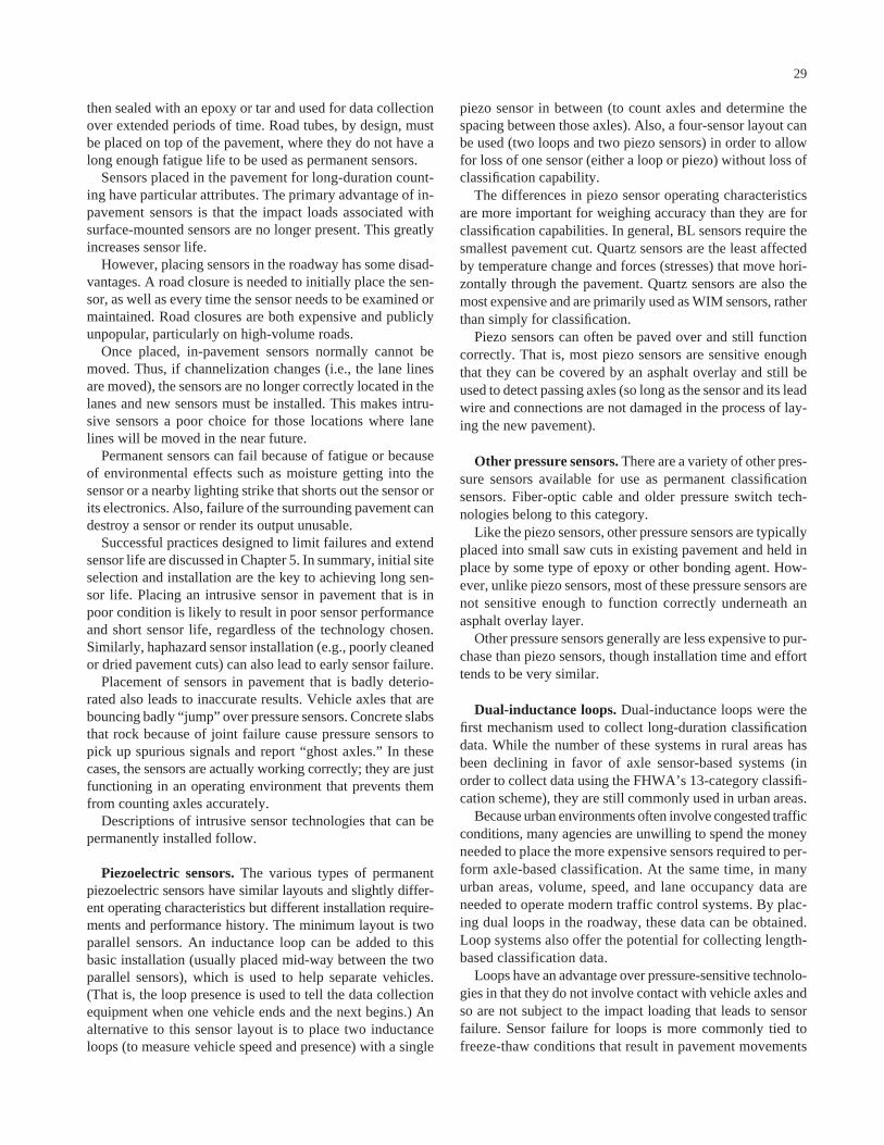
then sealed with an epoxy or tar and used for data collectionover extended periods of time. Road tubes, by design, mustbe placed on top of the pavement, where they do not have along enough fatigue life to be used as permanent sensors.
Sensors placed in the pavement for long-duration count-ing have particular attributes. The primary advantage of in-pavement sensors is that the impact loads associated withsurface-mounted sensors are no longer present. This greatlyincreases sensor life.
However, placing sensors in the roadway has some disad-vantages. A road closure is needed to initially place the sen-sor, as well as every time the sensor needs to be examined ormaintained. Road closures are both expensive and publiclyunpopular, particularly on high-volume roads.
Once placed, in-pavement sensors normally cannot bemoved. Thus, if channelization changes (i.e., the lane linesare moved), the sensors are no longer correctly located in thelanes and new sensors must be installed. This makes intru-sive sensors a poor choice for those locations where lanelines will be moved in the near future.
Permanent sensors can fail because of fatigue or becauseof environmental effects such as moisture getting into thesensor or a nearby lighting strike that shorts out the sensor orits electronics. Also, failure of the surrounding pavement candestroy a sensor or render its output unusable.
Successful practices designed to limit failures and extendsensor life are discussed in Chapter 5. In summary, initial siteselection and installation are the key to achieving long sen-sor life. Placing an intrusive sensor in pavement that is inpoor condition is likely to result in poor sensor performanceand short sensor life, regardless of the technology chosen.Similarly, haphazard sensor installation (e.g., poorly cleanedor dried pavement cuts) can also lead to early sensor failure.
Placement of sensors in pavement that is badly deterio-rated also leads to inaccurate results. Vehicle axles that arebouncing badly “jump” over pressure sensors. Concrete slabsthat rock because of joint failure cause pressure sensors topick up spurious signals and report “ghost axles.” In thesecases, the sensors are actually working correctly; they are justfunctioning in an operating environment that prevents themfrom counting axles accurately.
Descriptions of intrusive sensor technologies that can bepermanently installed follow.
Piezoelectric sensors. The various types of permanentpiezoelectric sensors have similar layouts and slightly differ-ent operating characteristics but different installation require-ments and performance history. The minimum layout is twoparallel sensors. An inductance loop can be added to thisbasic installation (usually placed mid-way between the twoparallel sensors), which is used to help separate vehicles.(That is, the loop presence is used to tell the data collectionequipment when one vehicle ends and the next begins.) Analternative to this sensor layout is to place two inductanceloops (to measure vehicle speed and presence) with a single
29
piezo sensor in between (to count axles and determine thespacing between those axles). Also, a four-sensor layout canbe used (two loops and two piezo sensors) in order to allowfor loss of one sensor (either a loop or piezo) without loss ofclassification capability.
The differences in piezo sensor operating characteristicsare more important for weighing accuracy than they are forclassification capabilities. In general, BL sensors require thesmallest pavement cut. Quartz sensors are the least affectedby temperature change and forces (stresses) that move hori-zontally through the pavement. Quartz sensors are also themost expensive and are primarily used as WIM sensors, ratherthan simply for classification.
Piezo sensors can often be paved over and still functioncorrectly. That is, most piezo sensors are sensitive enoughthat they can be covered by an asphalt overlay and still beused to detect passing axles (so long as the sensor and its leadwire and connections are not damaged in the process of lay-ing the new pavement).
Other pressure sensors. There are a variety of other pres-sure sensors available for use as permanent classificationsensors. Fiber-optic cable and older pressure switch tech-nologies belong to this category.
Like the piezo sensors, other pressure sensors are typicallyplaced into small saw cuts in existing pavement and held inplace by some type of epoxy or other bonding agent. How-ever, unlike piezo sensors, most of these pressure sensors arenot sensitive enough to function correctly underneath anasphalt overlay layer.
Other pressure sensors generally are less expensive to pur-chase than piezo sensors, though installation time and efforttends to be very similar.
Dual-inductance loops. Dual-inductance loops were thefirst mechanism used to collect long-duration classificationdata. While the number of these systems in rural areas hasbeen declining in favor of axle sensor-based systems (inorder to collect data using the FHWA’s 13-category classifi-cation scheme), they are still commonly used in urban areas.
Because urban environments often involve congested trafficconditions, many agencies are unwilling to spend the moneyneeded to place the more expensive sensors required to per-form axle-based classification. At the same time, in manyurban areas, volume, speed, and lane occupancy data areneeded to operate modern traffic control systems. By plac-ing dual loops in the roadway, these data can be obtained.Loop systems also offer the potential for collecting length-based classification data.
Loops have an advantage over pressure-sensitive technolo-gies in that they do not involve contact with vehicle axles andso are not subject to the impact loading that leads to sensorfailure. Sensor failure for loops is more commonly tied tofreeze-thaw conditions that result in pavement movements
sufficient to “cut” the wire placed in the pavement. They alsofail as a result of failing roadside amplifiers.
Given the weaknesses inherent in the collection of length-based vehicle classes, the primary drawback to loop systems(other than their susceptibility to freeze-thaw failure) is the factthat classification accuracy degrades significantly under con-gested conditions. Thus, significant quality assurance effortsare needed before data collected at congested, urban sites areaccepted as accurate measurements of truck volumes.
Undercarriage profile loops. A new technology hasrecently been released by several manufacturers that uses theshape of the inductance signature of passing vehicles to clas-sify the vehicle. While the specific technical approaches usedby the different manufacturers appear to be somewhat dif-ferent, the overriding concepts appear to be similar. In oneapproach, additional loops are used to help detect axles (bydetecting the change in inductance caused by presence of themetal in the axles), while in another approach, the shape ofthe primary inductance pattern itself is matched against theknown shape of specific vehicle types.
This approach shows more promise to allow sophisticatedclassification capabilities than previously available using looptechnology. At this time, however, these systems are rela-tively new, and little practical experience is available to deter-mine their accuracy and reliability.
Magnetometers. As with undercarriage profile loop clas-sifiers, several different versions of permanent magnetome-ters are being marketed currently. Some are placed directlyin the pavement, and others are inserted into conduits placedunderneath the pavement. Both styles of magnetometers mea-sure vehicle presence by monitoring changes in the earth’smagnetic field. The sensors are capable of estimating vehiclespeed and use that measure along with the duration of vehicledetection to estimate vehicle length. This length estimate isused to classify vehicles.
Note that the conduit style of magnetometer is frequentlyconsidered to be “non-intrusive” because the conduit can beplaced (by drilling under the pavement from the roadwayshoulder) without closing the lane of travel. The sensor canbe placed in the conduit without disrupting traffic, and thesensor can be repositioned within the conduit if lane geome-try is changed.
3.1.2 Non-Intrusive Technologies for Classification
While the majority of vehicle classification counting isperformed with intrusive or surface-mounted sensors, anincreasing percentage of classification counting is being per-formed with non-intrusive sensors. Non-intrusive technolo-gies include sensors that can be mounted overhead or to theside of the roadway.
30
Non-intrusive technologies have been available for vehi-cle detection and volume counting for a number of years,7
and improvements in computer processing power haveallowed these technologies to be extended to the more com-plex task of vehicle classification. In addition, with both thereduction in computer costs and the increased production ofnon-intrusive sensors resulting in economies of scale for theirmanufacture, the cost of many of these technologies hasdeclined considerably in the last 10 years.
Non-intrusive technologies have a number of distinct advan-tages over technologies that must be placed in or on the road-way surface, including the following:
• Increased staff safety (as staff do not need to be in theroadway in order to place the sensors),
• Less traffic disruption during sensor installation (as sen-sors can be placed with little or no traffic disruption,even on high-volume roadways),
• The ability to reorient the sensor to adjust for changinglane configurations or other geometric changes withouthaving to physically replace sensors,
• The capability of some non-intrusive sensors of collect-ing data on more than one lane at a time from a singlesensor (e.g., camera),
• Ease of maintenance and repair of above-ground sensorsin comparison with sensors that are placed in ground, and
• Not being subjected to many types of environmentaldamage that commonly reduce the sensor life of intru-sive sensors (e.g., freeze-thaw damage, tire impacts onexposed sensors, and pavement failure around sensors).
Non-intrusive sensors also have weaknesses. The biggestdrawback is the difficulty for non-intrusive sensors to countvehicle axles accurately, which is a key aspect of traffic loadestimation for pavement design. Some non-intrusive sensorsdo count vehicle axles, but these systems are limited in theirapplication and have either installation problems similar tointrusive sensors (i.e., they can only measure one lane of traf-fic without being placed at roadway level on the lane lines)or suffer from occlusion that occurs when a system cannot“see” one vehicle or axle because the sensor’s “view” of thatvehicle is blocked by an intervening vehicle.
As a result of their inability to easily count axles, mostnon-intrusive sensors classify vehicles by overall vehiclelength, similar to dual-inductance loop technology. Whilethis does not correlate directly with the vehicle classes com-monly collected by WIM systems, it does provide useful datafor pavement design purposes. Use of vehicle classificationsbased on overall vehicle length does require an additionaldata manipulation step for correlating these classes to thoseused by an agency’s WIM equipment. The staff time and the
7 Field Test of Monitoring of Urban Vehicle Operations Using Non-Intrusive Tech-nologies, FHWA, May 1997.
potential for error associated with this extra data processingstep must be traded off against the benefits obtained from useof non-intrusive technologies.
Currently, most non-intrusive classification counting isdone with permanently mounted sensors. Some vendors andseveral highway agencies have been exploring the develop-ment of portable versions of non-intrusive devices. Thesedevices usually consist of one of two designs. In one design,sensor arrays are mounted to poles, which are in turn mountedonto trailers fitted with a power source.8 The trailer is thentowed to the desired roadside location, and the pole is liftedinto position. This allows side-fired detection systems tooperate. The second style of system is designed to be tem-porarily mounted on existing highway infrastructure, usuallylight standards or highway signs.9 These portable systems arenot actively marketed in the United States.
As with intrusive sensors, the accuracy of non-intrusiveclassification systems is a function of the quality of the clas-sifier’s sensing system, the proper installation of the sensor,the placement of the sensor in an environment that is con-ducive to the proper operation of that specific technology, andthe vendor’s algorithm used to process the raw sensor data.
The placement of the sensor in a location where it willwork correctly is the most important variable that is withinthe control of the data collection agency. The starting pointfor this process is the ability to place the sensors where theycan properly sense the vehicles they are intended to classify.When sensors are mounted on the side of the road, it usuallymeans that they must be placed high enough to sense overvehicles in nearby lanes in order to count and classify vehi-cles in lanes that are farther away. Sensor height and angle ofview are also important for overhead-mounted sensors thatcollect data on more than one lane of travel. The specific sen-sor mounting locations required by each device will varywith the device and are not discussed in this report. Specificguidance on these details should be obtained from the ven-dor of each device. (However, it will be noted that overhead-mounted sensors tend to perform somewhat more accuratelythan the same sensor mounted at the roadside, all other thingsbeing equal. This is most likely a result of the overhead posi-tion generally having a better “field of view” than the road-side position.)
The specific technologies presented in this section include
• Video,• Radar,• Doppler microwave radar,• Passive infrared,• Active infrared,• Passive acoustic, and• Ultrasonic.
31
The accuracy of specific implementations of these tech-nologies was recently studied by a project jointly sponsoredby the U.S. DOT and the Minnesota DOT.10 The first round offield tests was completed in 2001, and the second round wascompleted in September 2002. While the study focused on thecollection of volume data using non-intrusive devices, theresults of these tests can be of considerable use to agenciesinterested in using non-intrusive data collection equipment. Apooled fund study specifically looking at portable use of non-intrusive devices has been proposed and is actively being pur-sued. Information on the completed and ongoing non-intrusivedetector tests can be obtained from http://www.dot.state.mn.us/guidestar/projects/nitd.html.
Video
Video detection is the most widely used of the non-intrusivedetection technologies. Video devices convert camera imagesinto digital representations (pixel images) and then use micro-processors to analyze those representations. There are twoprimary video image analysis techniques, trip line and imagetracking, with the trip line approach being the oldest and mostcommonly used.
In the trip line technique, a specific portion of the videoimage is defined as a “zone.” Pixels within this zone are mon-itored for change, and changes in pixels are used to determinewhen vehicles are entering or leaving the zone. (Zones invideo images can be considered “virtual inductance loops.”)Activations of virtual zones can be used to determine volumeand lane occupancy. Two or more consecutive zones (set ata known distance apart) can be used, just as dual-inductanceloops are used, to measure vehicle speed and consequentlyoverall vehicle length. This allows for vehicle classificationbased on total vehicle length.
Image tracking relies on pattern recognition algorithms todetect, recognize, and track specific kinds of vehicles. Thesesystems allow for more detailed data collection. (For exam-ple, they examine pixel images to detect axles, not just thepresence of a vehicle, in order to provide axle-based classifi-cations.) However, the complexity of the algorithms and short-comings of video image quality place additional constraints ontheir operation.
Video detectors of both types are sold by a number of dif-ferent vendors, and these systems can have very differentcapabilities. These differences are caused primarily by theuse of a variety of different data processing algorithms, eachof which has different strengths and weaknesses. While con-siderable experience has been gained as a result of the cur-rent use of these devices, the differences in specific vendorimplementations make it difficult to identify the differencesof those experiences.
8 This style of system has been used or tested in Ohio and New York among otherstates.
9 This style of system has been used or tested in Virginia and Minnesota among otherstates.
10 The Minnesota Guidestar Non-Intrusive Traffic Detection Tests http://www.dot.state.mn.us/guidestar/projects/nitd.html.
Factors that have been shown to affect video system per-formance adversely include
• Shadows (both stationary and moving shadows cast byvehicles);
• Direct sunlight;• Reflections caused by wet pavement and headlights;• Transition from light to dark or dark to light;• Wind-induced pole movement;• Environmental degradation of the video image caused
by (1) water on the camera lens, (2) icicles hanging infront of the camera lens, (3) salt grime on the cameralens, or (4) cobwebs on the camera lens; and
• Limited visibility caused by such phenomena as heavysnow, heavy mist, or dust storms.
Each of these factors creates artificial changes in pixelswithin the camera image (i.e., a change not caused by a vehi-cle passing through the image). Some of these causes aretransient environmental conditions, while others are more per-manent and require corrective maintenance action. (Note:camera-based systems may require more frequent mainte-nance activity than conventional loop-based systems.) Theaccuracy of counts obtained from these systems is largelydependent upon how effectively each system can deal withthese situations.
It is also apparent that the design and construction of sen-sor installations must take into account performance limita-tions. Camera lenses need to be protected as much as possi-ble from the elements. Similarly, placement of the cameras tominimize the effects of changing lighting conditions is alsoimportant for maximizing the performance of video-basedsystems.
The two primary strengths of video image detection are(1) the ability to easily move “virtual sensors” to adapt tochanging lane configurations or to the need for new sensorlocations and (2) the ability of field staff to use a video mon-itor to observe what the sensor is actually observing and toconsequently (and easily) make adjustments to the operationof the sensor.
Video detection has also the advantage of ability to collect,from a single video image, data on more than one lane of traf-fic at a time. The keys to collecting multiple lanes of datafrom a single camera are (1) the ability to obtain a clear videoimage of the lanes with sufficient pixel resolution to accu-rately monitor vehicle presence and (2) sufficient computingpower to monitor all “virtual detectors” in the image.
Radar
Conventional radar-based detection uses pulsed, frequency-modulated, or phase-modulated signals to detect vehicles.This technology is currently the only other non-intrusivetechnology that is designed to collect data from more than
32
one lane at a time with a single sensor. Radar technology hasbeen in use in the United States for a number of years.
Radar sensors can be either side-fired (mounted beside theroadway) or overhead mounted. A single, side-fired radar unitcan collect data on more than one lane, but a unit is requiredfor each lane if overhead mounting is selected. (Overheadmounting is more accurate, according to the manufacturer.)
Because radar technology is relatively immune to weatherconditions (snow, fog, etc.), it is used in a number of loca-tions where poor visibility conditions make video impracti-cal. Radar is easy to place, because side-fired systems can bepole mounted at a height of only 5 meters (15 feet), which isconsiderably lower than for video systems that must often bemounted as high as 10.7 meters (35 feet).
Finally, conventional radar has the ability to detect slow-moving and non-moving vehicles. This means that systemcount accuracy does not degrade significantly in stop-and-gotraffic conditions.
In some system tests, radar has slightly undercountedvehicles relative to counts made using conventional loopdetectors.11
Doppler Microwave Radar
Doppler microwave radar is a variation on conventionalradar systems. Doppler technology employs a continuouswave signal and measures the wave’s Doppler shift as it isreflected by passing vehicles. These detectors provide vehiclecounts and speeds, but are not capable of detecting stoppedvehicles and may be less applicable for the classification ofvehicles other than non-intrusive detectors.
Passive Infrared
Passive infrared devices detect the presence of vehicles bycomparing the infrared energy naturally emanating from theroad surface with the change in energy caused by the pres-ence of the vehicle. Because the roadway may generate eithermore or less radiation than a vehicle depending on the sea-son, the contrast in heat energy is detected.
As with radar detectors, passive infrared detectors can bemounted either on the side or overhead for data collection.These sensors provide the same detector output as conven-tional loops: vehicle volumes and presence. Monitoring thesefrom two consecutive sensor locations allows the computa-tion of vehicle speed and consequently overall vehicle length.
Sensor output from passive infrared appear to be unaf-fected by changes in weather conditions. While several ven-dors sell these devices on the U.S. market, there are a rela-tively small number of current installations.
11 Lawrence Klein, Michael Kelley, and Milton Mills, “Traffic Detection Technolo-gies for a Modern Transportation Infrastructure,” SPIE Conference 2592, CollisionAvoidance and Automated Traffic Management Sensors, October 25–26, 1995, Philadel-phia, Pennsylvania.
Active Infrared
Active infrared sensors differ from passive sensors in thata low-power laser beam is directed from the data collectiondevice to the road surface. Measurement of the time lapseduntil the reflected signal returns to the device is used to deter-mine the presence of a vehicle. By splitting the laser beaminto two separate signals from a single sensor, it is possible tocompute vehicle speed and overall length. This allows length-based classification from a single active infrared sensor.
Active infrared systems are also capable of measuringvehicle height and can thus create two- and three-dimensionalimages of passing vehicles. This allows even more compre-hensive vehicle classification capability.
Infrared sensors do have signal degradation during weatherconditions that reduce visibility. A good rule of thumb recom-mended by the Vehicle Detector Clearinghouse12 is that if vis-ibility drops to the point where the human eye does not see anobject clearly, then infrared sensors are also likely to experi-ence difficulties.
Passive Acoustic
Passive acoustic devices consist of an array of microphonesaimed at the traffic stream. The devices are passive in thatthey are listening for the sound energy of passing vehicles.The primary source of sound is the noise generated by thecontact between tires and road surface. At slower vehiclespeeds, the sound of the vehicle’s engine is more prominent.Passive acoustic devices are best used in a side-fired position,pointed at the tire track in a lane of traffic.
Acoustic detectors physically measure the changes in soundenergy radiating from the roadway. Increases in energy indi-cate the arrival of a vehicle, and decreases in energy indicateits departure. From these data, it is possible to determine laneoccupancy. By using multiple detection zones, it is possibleto estimate vehicle speed and length, thus allowing vehicleclassification by length.
Some models of acoustic sensors have been shown to besensitive to undercounting in cold temperatures. In addition,some acoustic sensors have a loss of accuracy when vehiclesare stopped or moving very slowly. These sensors are not com-monly used for classification purposes in the United States atthis time.
Ultrasonic
Pulse ultrasonic devices emit pulses of ultrasonic soundenergy and measure the time lapsed until the signal returnsto the device. When the sound energy returns more quickly
33
than the normal road surface energy returns, a vehicle is pres-ent. Signal analysis allows determination of vehicle presenceand occupancy. Using two closely spaced beams aimed aknown distance apart allows for computation of vehicle speedand consequently vehicle length. Pulse ultrasonic devices arecapable of high count accuracy when optimally mounted. Anoverhead mounting location provides a perpendicular reflec-tive surface, offering the best signal return.
Tests indicate that great changes in temperature and extremeair turbulence may inhibit accuracy of ultrasonic devices.Such devices are not commonly used in the United States atthis time.
3.2 WIM
This section discusses sensor technologies that provide theability to weigh vehicles. The systems must be capable ofsupplying axle weights and classifying vehicles into at leastthe 13 FHWA vehicle classification categories.
All WIM sensors currently used in the United States mea-sure transient forces applied by tires to sensors as vehiclespass over. They use the measured force to predict the weightapplied by the tire (axle) when the vehicle is at rest. The sen-sors used to perform this measurement include very thin, nar-row sensors placed directly in the pavement (fiber-optics,piezo cables); large plates resting in frames that are in turnimbedded in the pavement (bending plates, hydraulic loadcells); instrumented roadway structures (bridge and culvertWIM); and flat sensors placed on top of the road surface(capacitance pads). Selecting a specific technology requiresconsidering the following factors:
• Cost of the sensors and their installation,• Locations where a given technology can be successfully
installed,• Sensitivity of sensors to various factors (temperature,
vehicle dynamics, traffic volume, and speed),• Expected life span of sensors, and• Robustness of sensor installation (e.g., the ability to
continue to collect data if one or more sensors fail or tocompare output of one sensor against another).
The WIM task is heavily complicated by the dynamicmotion of trucks being weighed. As trucks move, they bounce.The degree to which each truck bounces is a function ofpavement roughness, vehicle load, environmental conditionssuch as wind, and each vehicle’s design and suspension sys-tems. The greater the amount of vertical motion exhibited bytrucks, the more difficult the task for WIM systems to accu-rately estimate static axle loads.
Thus, for all WIM technologies, a key issue for collectingaccurate weight data is to select locations for data collectionthat minimize the dynamic motion of trucks being weighed.The lower the vertical dynamic motion of passing trucks, the
12 Mimbela and Klein, A Summary of Vehicle Detection and Surveillance Technolo-gies Used in Intelligent Transportation Systems, prepared by the Vehicle DetectorClearinghouse, for FHWA, Fall 2000.
more accurate the WIM scale, regardless of the technologyselected.
The other step required to account for truck dynamics is tocalibrate the WIM scale to the unique traffic characteristicsof each data collection site. While it is possible to calibrateeach sensor in the laboratory, it is not possible to account forthe dynamic motion of trucks at a specific roadway site with-out measuring those forces in the field at the location wherethe sensor is being placed. Only direct comparison of WIMsystem output against known axle weights for specific vehi-cles allows the calibration needed to enable a WIM systemto accurately predict static axle weights. While many vendorssupply autocalibration features with their WIM systems, auto-calibration depends on one or more key assumptions that alsomust be calibrated to each specific site.
3.2.1 Portable WIM Operations
There are only two technologies commonly used for por-table WIM data collection in the United States: capacitancemats and piezoelectric (BL-style) sensors, although a numberof states used bridge WIM systems in a portable fashion in thelate 1980s and early 1990s. These three technologies are dis-cussed in this section. Finally, some states perform portableoperations by moving electronics from one set of perma-nently mounted sensors to another. This style of “portable”data collection will be treated as permanent operations sim-ply because the sensors themselves are permanently placedin the roadway.
Capacitance Mats
A capacitance mat consists of two metal sheets separatedby dielectric material. An outer surface layer surrounds thesensor, protects the steel plates, and allows the sensor to beplaced on the pavement. A voltage is applied across the twometal plates. When a vehicle crosses over the plate system,it causes the distance between the two plates to decrease,which increases the capacitance of the system. Measure-ments of the resonance frequency of the circuit allow the esti-mation of axle weight as it is applied to the sensor system.
A typical portable capacitance mat system covers one-halfof a lane and measures one side of each passing axle. It isusually secured to the roadway surface using a combinationof asphalt nails and tape. Portable loops are usually alsoplaced as part of the system installation in order to providemeasures of vehicle presence and vehicle speed.
Capacitance mats are moderately priced (each pad is about$10,000, not counting data collection electronics) and light-weight. Installation requires several people, however, both tohelp place the sensors and to provide traffic control and cal-ibration assistance. Use of portable capacitance mats allowsWIM data collection to take place on the outside lane ofalmost any level roadway that has a reasonable shoulder.
34
(Capacitance mats are difficult to use on inside lanes becausethe lead wires and sensor connections must be exposed totraffic in those positions.)
Portable capacitance mats have significant shortcomingsin terms of overall system accuracy. The primary ones arethat (1) the system only weighs one side of passing axles and(2) the sensor itself is fairly thick, creating a “bump” in theroad that both increases vehicle dynamics and causes animpact load on the sensor that degrades system accuracy.These shortcomings cause accuracy from portable systems tofall below that of flush-mounted, full-lane width, permanentWIM systems.
Accuracy limitations are also inherent in the placement ofmats on the roadway. While mats can be initially calibratedat a control location, the effects of vehicle dynamics at eachgiven data collection location can only be determined by site-specific calibration efforts. The cost of these efforts often farexceeds the cost of placing and retrieving the data collectionsensors and greatly increases the cost of collecting accurateweight data with these systems. While many states limit theamount of site-specific calibration done with their portablemat systems, the lack of site-specific calibration significantlyaffects the mat’s ability to accurately estimate the static axleweights needed for the pavement design process.
Piezoelectric Sensors (BL and Ceramic Cable)
The primary alternative to capacitance mats currently usedby state highway agencies for high-speed portable WIM datacollection is thin-strip piezo sensors. There are two basicstyles of thin-strip piezo sensors: a flat plate configuration(the BL sensor) and unmounted piezoceramic coaxial cable.
Both systems operate on the same basic principle. When amechanical force is applied to a piezoelectric device, it gen-erates a voltage by causing electrical charges of oppositepolarity to appear at the parallel faces of the piezoelectriccrystalline material. The measured voltage is proportional tothe force or weight of the wheel or axle. The piezoelectriceffect is dynamic (i.e., charge is generated only when theforces are changing); piezoelectric sensor systems can onlybe used in applications where vehicles are moving at speedsnot less than 10 mph. Piezoelectric sensor systems cannot beused in applications having either slow-moving traffic or stop-and-go traffic.
For portable weighing operations, sensors (each sensor isroughly one lane width in length) are taped to the roadway,perpendicular to traffic. Normally, two sensors are placed ameasured distance apart. The time difference between axlecontact on the two cables is used to determine vehicle speed,which is then used to determine the axle spacings needed forvehicle classification.
These systems are relatively easy to set up, although, likecapacitance mats, they are routinely placed only in the out-side lane of traffic in order to allow the lead wires to be placed
on the roadway shoulder. The sensors themselves are lessexpensive than individual capacitance mats.
However, like the capacitance mat systems, piezo cablesused in portable operations suffer from significant limitationsin accuracy for the following reasons:
• Sensors are temperature sensitive, making it difficult tokeep them in calibration when temperature changes dur-ing the day.
• The sensors’ narrowness allows tires being weighed to“fold” over them, meaning that at no time during theaxle weighing process is an entire tire isolated on thesensor. Therefore, changes in tire pressure or tire-treadpatterns affect the force measured by this type of sensormore significantly than many other WIM technologies.
• The same site-specific calibration problems that affectall portable WIM systems also affect these systems (cal-ibration of the sensors to site-specific vehicle dynamicsis necessary to obtain the level of accuracy needed fordirect inclusion of these data into the pavement designprocess).
• Sensors have a relatively high signal-to-noise ratio.
Bridge WIM
In the 1980s and early 1990s, a number of states instru-mented bridges for use as WIM platforms. The technologyworks by measuring the response to traffic loads as measuredby strain gauges attached to girders under the bridge. A num-ber of European countries are still strong supporters of bridgeWIM, and Australia extensively uses a similar system basedon the deflection of culverts.
Portable operations were achieved by attaching the straingauges, either with C-clamps or permanently, and then con-necting portable roadside electronics to those gauges whendata collection was desired.
Bridge WIM has the advantage of having a very largeweighing platform: the bridge deck itself. This helps limit theeffects of vehicle dynamics. Unfortunately, various other fac-tors degrade the signal from the strain gauges and limit theaccuracy of data from bridge WIM. The most significant ofthese factors are the presence of other traffic on the bridge atthe same time a truck is being weighed (which significantlyincreases the noise in the weight signal) and the fact that statescould not adequately define the expected response of manybridges to given loading conditions (which limits the accuracyof the computation of loads based on bridge response).
Currently, without extensive site-specific set-up, calibra-tion, and testing, bridge WIM is considered reliable only onshort-span, simply supported, steel girder bridges where truckscan be isolated on the span during the weighing process. How-ever, the Australians use a similar WIM technology called“CULWAY” that works on a similar principle (measuring thestrain of the underside of a structure), but is attached to theunderside of large culverts rather than to bridge girders. Use of
35
this technology may increase the number of structures suitablefor use as weight sensors.
Conventional Static (Loadometer) Scales
For low-volume roadways, it is also possible to collecttruck weight data with portable static scales used for truckweight law enforcement. Any scale that meets Handbook 44standards13 is acceptable for truck weight data collection.
Collecting data with static scales requires either a perma-nent scale facility or a level, paved surface where trucks canbe pulled off the road safely. This requirement significantlylimits the locations at which data can be collected.
Significant numbers of workers are needed to perform thistask. Weighing vehicles statically is a slow process and resultsin a dataset of limited size. On high-volume roads, this smalldataset can easily represent a biased estimate of actual trafficloads, especially if by-pass routes exist, that might bias theweights of trucks being sampled. However, on low-volumeroads with little bypass opportunity, this approach to weightdata collection can provide an accurate and complete mea-sure of truck traffic for the periods for which the highwayagency can afford to collect data.
A number of low-speed WIM systems can be used to speedup this process, while maintaining good data quality. Infor-mation on such systems can be found on the FHWA Demon-stration Project 121 web site http://www.ornl.gov/dp121/.
3.2.2 Permanent WIM Operations
The majority of WIM data collection is now done withpermanently installed weight sensors, although many statesdo not collect data continuously at these sites. Instead, theyattach data collection electronics to previously mounted sen-sors when data collection is desired. The scale sensors arethen calibrated (or should be calibrated), and data are col-lected for the desired time period.
Permanently mounting WIM sensors allows them to beinstalled flush with the roadway surface. When done prop-erly, this eliminates the bump that vehicles experience whencrossing surface-mounted sensors. The removal of impactloads on sensors and the elimination of extra vertical motioncaused by bumps result in improved system accuracy.
Permanently mounting sensors flush with the pavement sur-face also decreases the impact loads on sensors themselves,which in turn increases sensor life. One common cause of sen-sor failure is when sensors become directly exposed to hori-zontal forces from tire contact. This exposure often leads toearly fatigue failure for both sensors and the bonds between
13 Tina G. Butcher et al., Specifications, Tolerances, and Other Technical Require-ments for Weighing and Measuring Devices: As Adopted by the 83rd National Con-ference on Weights and Measures, 1998, ISBN #0-16-049825-2.
sensors and pavement. Exposed sensors are also highly sus-ceptible to damage from contact with snowplow blades.
As noted in Section 2.2.1, a variety of other factors playimportant roles in both the output accuracy and the life ofpermanently mounted sensors. Pavement at permanent sen-sor locations should be
• Flat (no horizontal or vertical curves),• Smooth (no bumps or other surface conditions that
increase dynamic vehicle motion),• Strong (to reduce pavement flex underneath the WIM
sensor), and• In good condition.
Flat, smooth pavement reduces vehicle dynamic motion andincreases the accuracy of all WIM sensors. Strong pavementresults in longer lived pavement, which in turn increases sen-sor life. Strong pavement is especially important for stripsensors that are embedded directly into the pavement. Theoutput from these sensors depends on the performance of thepavement itself. If pavement strength varies significantlyover time (e.g., with environmental conditions), sensor out-put will also vary, and this greatly decreases the likelihoodof accurate sensor calibration. Some researchers have sug-gested criteria for the pavement strength required for installingWIM equipment based on falling weight deflectometer (FWD)measurements. These criteria stipulate a maximum deflec-tion under the center of the applied load and a minimumdeflection basin area.
Good condition pavement reduces vehicle dynamics andmakes the bond between sensors and pavement more likely tolast. A common cause of sensor failure is the failure of sensor/pavement bonds, which is often traced to poor pavement con-dition. Poor installation is another common cause of this fail-ure. Poor cleaning or drying of pavement cuts results in a weakbond that allows moisture intrusion and further deteriorationof the bond.
Moisture is also a common cause of equipment failurebecause of intrusion into either the sensor itself or the com-munication lines connecting the sensor to the data collectionelectronics.
Each vendor and each state highway agency has its ownprocedures for fighting moisture intrusion. Similarly, agenciesand vendors have equipment and procedures for protectingpermanent equipment from lightning strikes, other environ-mental effects (extreme temperatures, humidity, dust), insects,power surges, and various other causes of equipment or com-munications failure. No single document exists that lists bestpractices for protecting equipment from these common prob-lems. The U.S. Department of Transportation has recentlystarted promoting information exchanges between state high-way agencies in order to increase the sharing of knowledgein these areas.
Specific WIM system technologies that can be used forpermanent, continuous weight data collection are
36
• Piezoceramic sensors,• Piezopolymer sensors,• Piezoquartz sensors,• Bending plates,• Hydraulic load cells,• Bridge and culvert WIM systems,• Capacitance mats, and• Other WIM technologies (fiber-optic, subsurface strain
gauge, multi-sensor).
Each of these technologies is introduced briefly below.
Piezoceramic Sensors
As noted above, piezoelectric WIM sensors come in vari-ous forms, but all systems operate on the same basic princi-ple. When a mechanical force is applied to a piezoelectricdevice, it generates a voltage by causing electrical charges ofopposite polarity to appear at the parallel faces of the piezo-electric material. The measured voltage is proportional to theforce or weight of the wheel or axle and is transmitted by thesensor to electronics that measure and interpret the voltagesignal.
The first piezo traffic sensor marketed in the United Statesuses a ceramic powder compressed between a solid core andan outer sheath of copper. The cable is about the size of con-ventional coaxial cable. When used as permanent WIM scalesensors, the cable is most commonly placed in aluminumchannels filled with epoxy resin or another substance. Thechannel is then placed so that the top of the sensor is flushwith the road surface, in a slot cut into the pavement, lessthan 2 inches wide. (Different vendors use slightly differentsensor mounting techniques.) Routine site installations canconsist of two piezoceramic sensors, two sensors plus aninductance loop, or one piezo sensor and two inductance loops.
Each of these configurations allows for the computation ofvehicle speed and, consequently, axle spacing, which in turnpermits vehicle classification as well as axle weighing. Theinstallations using two piezo sensors tend to provide betterestimates of static axle weights because each sensor providesan independent measure of axle weight during a differenttime period associated with the vertical motion of the vehiclebeing weighed. Combining the two independent weight esti-mates generally improves the accuracy of the static weightestimate.
The piezoelectric effect generated by the sensor is dynamic.That is, the charge is generated only when the forces appliedto the sensor are changing. As a result, piezoelectric sensorsystems can only be used in applications where vehicles aremoving at speeds not less than 10 mph; they are not reliablein slow-moving or stop-and-go traffic.
In addition, it is difficult to construct a cable for these sen-sors that has uniform response across its entire length. Strictlaboratory testing is done to ensure that cables used for weigh-ing meet uniformity standards. Cables that successfully pass
uniformity tests are called “Class 1” sensors. Sensors thatfunction correctly but do not meet the highest signal unifor-mity standards are designated as “Class 2” sensors and can beused for vehicle classification purposes, but not for weighing.
Piezoceramic sensors produce weight estimates of averagequality. They suffer from three significant limitations in sys-tem accuracy: temperature sensitivity, reliance on the pave-ment itself for structural support, and narrow sensor design.
Because the piezoceramic sensor is temperature sensitive,piezoceramic WIM systems must include various algorithmsand/or additional sensor inputs that allow the WIM system toaccount for temperature changes when estimating weights.Each equipment vendor tends to approach this problem dif-ferently, and different levels of success are achieved. Thetechnical process is further complicated by the fact that sen-sors are placed directly in the pavement structure and, becausemany pavement structures have structural responses that arealso temperature dependent, this also affects the piezo’s signalstrength for a given load. Consequently, the sensor response isaffected by two independent (but related) sources of varia-tion in signal strength, and these lead to errors in estimatedaxle weights.
The narrow-sensor design is an advantage when it comesto the time and cost required for installation. However, thenarrow sensor also means that tires being weighed are neverisolated on the sensor. That is, during all points in the weigh-ing process, at least part of the tire is being supported by thepavement surrounding the sensor and not the sensor itself.Thus, the sensor never senses the entire force applied by atire. This effect is exacerbated by some tire tread designs thatcan concentrate forces on small surface areas, and those sur-faces may or may not be directly on the sensor itself. Thecombination of these effects is that the sensor can sense avariety of different forces, and this results in a larger errorwhen estimating static weights than with some other WIMtechnologies.
Piezopolymer Sensors
The second common piezo technology uses a piezoelectricpolymer surrounded by a flat brass casing. This sensor, com-monly called the BL sensor, is placed directly on the road forportable weighing but, like the piezoceramic cable, is com-monly placed into an aluminum channel filled with epoxyresin when being used as a permanent WIM sensor.
This sensor is used exactly as the piezoceramic cable isused and has essentially the same benefits and drawbacks.The BL sensor is also temperature sensitive, and the piezo-electric effect it generates is dynamic. It is not a reliable sen-sor in slow or stop-and-go conditions, and additional steps areneeded when processing sensor output to account for changesin sensitivity because of changing temperatures. Finally, likethe piezoceramic cable, it comes in Class 1 and Class 2 con-figurations, which indicates the degree of sensor uniformity.
37
Piezoquartz Sensors
The piezoquartz sensor was recently introduced in theUnited States. It differs from the other piezoelectric sensorsboth in the piezoelectric material used and in the design ofthe sensor itself, although it still fits into a pavement cut gen-erally less than 2 inches wide.
While it is more expensive per sensor than the other piezo-style sensors, the quartz sensor has the distinct advantage ofbeing insensitive to changes in temperature. It is thereforegenerally more accurate than other piezo sensors. However,because the sensor still relies on structural support from thepavement, if the pavement structure is sensitive to tempera-ture, the sensor will show some change in response to a givenaxle load simply as a result of the change in pavement strengthwith changing environmental conditions. This sensor is notsensitive to changes in temperature or soil moisture if placedin a thick portland cement concrete pavement. However, out-put from this sensor is likely to be sensitive to changes intemperature, although not as much as other piezo sensorswould be, if placed in a moderately thin asphalt pavement.
Like other piezo sensors, this sensor is placed into a rela-tively small slot cut into the pavement. Each sensor is roughly1 meter (3 feet) long, so four sensors are placed in an end-to-end arrangement to instrument an entire 12-foot traffic lane.The site installation can consist of two lines (eight sensors)of piezoquartz sensors, two lines plus an inductance loop, orone line of piezo sensors and two inductance loops.
As with other piezo installations, each of these configura-tions allows for the computation of vehicle speed and, conse-quently, axle spacing, which in turn allows vehicle classifica-tion. The installations using two piezo lines tend to providebetter estimates of static axle weights, because each line pro-vides an independent measure of axle weight, and the aver-aged weight estimate can be used to account for the dynamicmotion of the vehicle more effectively than a single line ofsensors.
Real-world experience with piezoquartz sensors is stillbeing gained in the United States, but the sensor appears tooffer accuracy on a par with bending-plate systems wheninstalled in structurally strong pavements.
Bending Plates
Bending-plate WIM systems use plates with strain gaugesbonded to the underside. As axles pass over the bendingplate, the system measures the strain on the plate and calcu-lates the load required to induce that level of strain.
Individual bending plates are generally 6 feet long androughly 2 feet wide. One bending plate is generally installedin each wheel path. In some cases they are installed aligned,while in other cases the right and left wheel path plates arestaggered in order to measure tire loads at two different pointsin the vehicle’s dynamic path. A typical bending-plate site alsoincludes two inductance loops used to detect approaching
vehicles, to differentiate between closely spaced vehicles, andto measure speed.
Bending plates are mounted flush with the roadway intosteel frames placed in the pavement. The use of steel framesseparates the plate sensor from the roadway structure andincreases the accuracy of the weight measurement in com-parison with strip sensors. In addition, the weighing platformis large enough to isolate each tire as it is weighed. This alsonegates the bridging effect from which strip sensors suffer, aswell as limiting the effect that different tire pressures andtread designs have on the forces exerted on the scale platform.
Tests of system performance generally indicate that bend-ing plates are more accurate than traditional piezo cable andcapacitance mat WIM systems and are roughly equivalent inaccuracy to piezoquartz sensors, but are less accurate thanhydraulic load cells. However, differences in weighing accu-racy that result from technological differences between WIMsystems are often overshadowed by problems inherent withspecific weighing installations. (For example, a load cellplaced in rough pavement will provide less accurate datathan a bending-plate system placed in smooth pavement.)
The cost and installation time required to place bending-plate systems also falls between that of piezo and load-cellsystems. Because placement of the steel frame involves amore substantial pavement cut than is required for the stripsensor installation, the duration of the lane closure requiredfor system installation is far longer than for piezo systems.However, the time required for bending-plate installation isconsiderably less than that required for load-cell installation.
Hydraulic Load Cells
As with most of the WIM technologies, there is more thanone high-speed hydraulic load-cell WIM system design inthe United States. The most common versions operate bytransferring wheel weights applied to the weighing platformto one or more hydraulic cylinders containing oil. Changesin the hydraulic pressure are correlated with axle weights.The most common load cell design uses two in-line scaleplatforms that operate independently and provides weightestimates for the right and left tires of each axle. The systemrecords the weights measured by each scale and sums themto obtain the axle weight. Off-scale detectors are frequentlyintegrated into the scale design to detect any vehicles off theweighing surface. In addition, at least one inductive loop andone axle sensor are usually included as part of the systemdesign. The inductive loop is placed upstream of the load cellto detect vehicles and alert the system of an approachingvehicle. The axle sensor is usually placed downstream of theload cell to determine axle spacings and vehicle speed. If asecond inductive loop is used in place of the second axle sen-sor, it is placed downstream of the load cell to determinevehicle speed, which is needed to determine axle spacings.
The deep-pit load-cell system is generally considered themost accurate of the available conventional high-speed WIM
38
systems. It is generally insensitive to changes in temperatureand can weigh vehicles at both low and high speeds. It is, how-ever, the most expensive WIM system to purchase and install.The term “deep-pit scale” comes from the fact that this loadcell itself requires a significant excavation in the roadway forinstallation. This means long lane closures are required forsensor installation. Heavy construction equipment is neededto dig installation pits and place sensors and associated elec-tronics. However, the fact that considerable construction isinvolved normally means that sensors are only placed at loca-tions with smooth pavements (or pavements are made smoothat the time of sensor installation). Thus, hydraulic load cellstend to be correlated with “expensive” installations, which inturn result in better system performance.
Load cells are contained in a steel frame that is indepen-dent of the pavement. This makes the load cell’s response toaxle weights insensitive to changes in pavement strengthcaused by changes in environmental conditions (i.e., temper-ature and moisture content). In addition, the weighing plat-form is large enough to isolate each tire as it is weighed. Thisagain eliminates the negative effect pavement strength has onstrip sensors, as well as limiting the effect different tire pres-sures and tread designs have on the forces exerted on thescale platform.
Bridge and Culvert WIM Systems
In bridge WIM systems, strain gauges are placed on theunderside of bridges or on the girders of bridges. Strain-gauge output is analyzed to determine the loads on specificvehicle axles. While the number of bridge WIM installationshas declined in the United States since the late 1990s, con-siderable research on this subject is still being performed inEurope. Information on this research is available at http://wim.zag.si/wave/download/wp12_report.html.
Culvert WIM is a variation of bridge WIM and is exten-sively used in Australia. In this system, strain gauges areattached to the underside of large culverts, and the strainmeasurements obtained are used to estimate truck axle loads.The short span of the concrete culvert and the relatively sim-plistic design of the culvert make the analysis of the strainsignal straightforward, thus eliminating several of the prob-lems experienced by bridge WIM systems used in the UnitedStates.
While the culvert-based system has been marketed in theUnited States, it is not widely used at this time.
Capacitance Mats
Capacitance mats consist of two metal sheets separated bya dielectric material. An outer surface layer surrounds thesensor, protects the steel plates, and allows the sensor to beplaced on the pavement or in a mounting frame. A voltage isapplied across the two metal plates. When a vehicle crosses
over the plate system, it causes the distance between the twoplates to decrease, which increases the capacitance of thesystem. Measurement of the resonance frequency of this cir-cuit allows the estimation of the weight of each tire as it isapplied to the sensor system.
Permanently mounted capacitance mats differ from portablemats in that the former mats are placed in steel frames thatare installed in the pavement surface. This allows the surfaceof the mats to be flush with the roadway and improves theaccuracy of the system. It also reduces the impact load on thesensor itself, both increasing sensor life and decreasing thepotential for the sensor to be dislodged from the roadway.
Most capacitance mat systems rely on weighing only onewheel path. This limitation makes them slightly less accuratethan other potential WIM system alternatives. However, ven-dors do sell permanent capacitance mat systems that use matsin both wheel paths.
Other WIM Technologies
New WIM technologies continue to be developed andbrought to the market. Many of the new technologies havebeen developed specifically to address limitations in the cost,performance, and flexibility of current technologies. The sys-tems discussed below are either in active use elsewhere in theworld or in active development in the United States:
• Fiber-optic sensors detect the presence of a load bymeasuring the decrease in optical transmission causedby constriction of the fibers when vehicles pass oversensors. Fiber-optic sensor systems contain light trans-mitters (usually a light-emitting diode), photon detec-tors, and signal analysis hardware and software in addi-tion to the fiber sensor itself. The potential advantagesof fiber-optic sensors are relative insensitivity to roadtemperature and low cost. Fiber-optic sensor systemsare not fully developed and are not in field operationaluse. System accuracy and life have not been established.
• Capacitance strip sensors have been used in the UnitedKingdom for a number of years. These sensors use thesame basic principle as capacitance mats (describedabove), but use a thin sensor (instead of the larger mat)designed for in-pavement installation similar to piezo-sensor deployment. The capacitance sensor material wasselected to avoid the temperature sensitivity problemsassociated with piezoceramic and piezopolymer sen-sors. However, only limited testing of this sensor hasbeen done in the United States, and the sensor is notactively marketed in the United States.
• Subsurface strain-gauge frame technology is currentlybeing tested at Virginia Polytechnic Institute and StateUniversity. This technology places a steel frame fittedwith a large number of strain gauges underneath the pave-ment. (The 2-ton frame is installed at least 2 inches underthe pavement surface and can be completely below the
39
roadbed.) The scale sensor is placed by removing theexisting pavement at the site and repaving once the scaleis correctly positioned. The sensor’s strain gauges reg-ister the strain transmitted through the pavement to thesteel frame. A neural network computing algorithm thenconverts these signals to estimates of vehicle and axleweights. The system uses the pavement structure todampen the effect of vehicle dynamics and to increasesensor life by limiting the fatigue problems associatedwith repetitive tire contact and pavement maintenanceactivities. The manufacturer claims that the sensor systemis maintenance free. The testing being performed willdetermine whether the neural network processing algo-rithm is able to accurately estimate weights given themitigating effects of the overlying pavement structure.
• Multi-sensor WIM is one of the bigger research issuesin Europe’s WAVE (“WIM of Axles and Vehicles forEurope”) program. The concept is to use a larger num-ber of moderately priced sensors to weigh a given vehi-cle multiple times during a single pass. By stretchingthese sensors over many meters, it is possible to deter-mine a vehicle’s dynamic motion and thus significantlyimprove the estimate of vehicle weight. The use of mul-tiple sensors also provides multiple independent mea-sures of the same basic quantity. While this techniqueshows considerable promise, it is unclear if it is eco-nomically feasible or if the improvements in accuracyachieved warrant the cost of additional sensors and theirplacement.
A number of states and vendors have moved to take advan-tage of the concept of multi-sensor WIM without taking theapproach the European WAVE program tested. In Europe,multi-sensor WIM systems deployed a large number of sen-sors (10 or more). In the United States, vendors and states haveboth increased the number of sensors deployed and changedthe location of sensors in order to improve the measurement ofvehicle dynamics. However, they have not increased the num-ber of sensors to the extent examined in the European tests.The increase in sensors allows a more accurate measurementof (and accounting for) the variation in axle weight caused byvehicle motion. However, by limiting the number of sen-sors added, the increase in capital cost and installation timerequired to build the WIM site is moderated.
One fairly common approach to multi-sensor WIM in theUnited States has been to use three half-lane bending platescales (rather than the traditional two sensors) and to staggerthe left wheel path and right wheel path sensors (rather thanplacing them side by side). This allows measurement of bothsides of the vehicle and provides measurements at three dif-ferent points in the dynamic spectrum while only increasingthe sensor cost by 50 percent.
Another common approach is to place four staggered setsof half-lane piezo sensors. The concept is the same for thissystem as for the bending plate system, in that staggering the

sensors yields more information on the dynamic variation ofaxles, while, in this case, there is no actual increase in the num-ber of sensors required when compared with a conventionalpiezo-based layout (i.e., two full lanes’ worth of sensors).
Both of these designs also have the advantage of providingan extra layer of site reliability. This is because the extra sen-sors allow “graceful degradation” of the WIM system. Thatis, the loss of one sensor does not make the WIM data unus-able; it simply degrades the accuracy of the system somewhat.
40
In the case of the bending-plate system described above, theloss of one of the two right bending plates actually leaves thesite as being equivalent to a conventional bending-plateWIM site in terms of sensor accuracy.
Note that before such an approach is adopted, the highwayagency must make sure that the vendor’s data collection elec-tronics can both handle any additional sensor inputs and cor-rectly interpret the signals coming from sensors placed in astaggered position.
41
CHAPTER 4
A PROCESS FOR SELECTING EQUIPMENT
Each of the technologies discussed in Chapters 2 and 3 hasstrengths and weaknesses for collecting classification andweight data. Under the right conditions, most of the tech-nologies can collect data of the quality needed for estimatingtraffic loads for the pavement design software. However,each of these technologies can perform very poorly whenplaced in environments that are not conducive to the tech-nology being used or when used incorrectly.
As a consequence, the state highway agencies most suc-cessful at data collection own and operate more than one typeof vehicle classification and/or WIM equipment. Differenttypes of equipment are used in different operating environ-ments. This helps ensure the quality of data that are collected,but also forces understanding of and accounting for minor dif-ferences in data supplied by different devices. (For example,some agencies use dual-inductance loops to collect length-based truck classification data on urban freeways but axlesensor-based counters to collect classification data on ruralroads. Special studies are needed to correlate these two datacollection schemes. But through the use of detectors placed tocollect traffic operations data, these simple correlation stud-ies provide access to large amounts of important truck countinformation that could not be collected otherwise.)
Selecting technologies (and vendors) requires careful analy-sis of three different types of information:
• Data collection needs of users,• Data handling requirements and capabilities of the high-
way agency, and• Characteristics of available makes or models of equip-
ment (e.g., cost, reliability, and data provided).
Within each of these general subject areas are a variety ofimportant issues. It is each agency’s responsibility to explorethese issues and to balance the advantages and disadvantagesof each technology when selecting equipment both in generaland for specific data collection implementations.
The material presented below briefly describes the issuesthat need to be considered when agencies select equipment forvehicle classification and/or truck weight data collection. Inaddition, Chapter 5 presents a series of best practices recom-mendations that describe tasks needed to ensure the collectionof reliable, accurate traffic data. Adoption of these practices,or of variations in these practices, is likely to improve the
quality of the data collected and reduce the overall cost of thedata collection effort.
4.1 DATA COLLECTION NEEDS
The traffic data needs for the pavement design software arebeing addressed in detail under other tasks of NCHRP Project1-39. These needs require capability to collect the following:
• Short-duration (48-hour) classification counts on roadsand road segments where traffic loads will be needed,
• Long-term classification counts (i.e., data collected formore than 1 year) at a limited number of locations aroundthe state, and
• WIM data collection at a limited number of locations.
These capabilities are consistent with the general agencycounting needs identified in the FHWA’s Traffic MonitoringGuide as meeting the needs of a wide variety of users.
The specifics of the required data collection efforts aredivided into vehicle classification issues, location issues, andcount duration issues.
4.1.1 Classification Issues
A good starting point when examining data collectionequipment is the type of classification scheme the equipmentis capable of providing. Axle-based classifications are pre-ferred for pavement design purposes, but length classificationis acceptable when axle classes cannot be reliably collected.
Truck characteristics (overall length, axle spacing, etc.)tend to differ from state to state. Each state highway agencyshould have an algorithm they have tested and certified thatcan correctly convert axle count and spacing information intoaccurate vehicle classification. Can this algorithm be imple-mented with the proposed equipment? If not, what flexibilityis offered by the vendor in the classifications supported, andhow do those classes correlate with the FHWA’s 13 classesor the classification system used by the state highway agency?Finally, if a classification algorithm other than the one testedand approved by the highway agency must be used, the agencymust thoroughly test the new algorithm. Acceptance of thenew data collection equipment should be contingent on the
satisfactory performance of the equipment in that test, andthe highway agency should use those results to understandhow data collected with the new device correlate with thedata collected using the agency’s WIM scales.
4.1.2 Location Issues
Often the classifications collected are not driven by the pref-erences of the user, but by the constraints of the location atwhich data must be collected. A number of location-specificconstraints can affect the choice of data collection technology.Key location-specific constraints and their effects include thefollowing:
• Is the data collection site urban or rural oriented? (Thatis, is congestion likely to be present? Are vehicles oftenformed into closely space platoons?) Devices that workeffectively in uncongested rural areas often do not workeffectively in more congested urban conditions. (Testsperformed by Minnesota Guidestar in 2001/2002 shouldprovide guidance on which non-intrusive devices canaccurately collect data in urban conditions. Seehttp://www.dot.state.mn.us/guidestar/projects/nitd.html.)
• Are there traffic signals or other control devices nearbythat may affect vehicle speeds and/or spacings? (Classi-fication and WIM equipment should not be located nearsignals because vehicles frequently accelerate and decel-erate near intersections, causing problems in the perfor-mance of most classification and weight data collectiondevices.)
• At what speeds are vehicles traveling? (Some devices donot operate at very low traveling speeds, while others arenot effective at very high traveling speeds.)
• On how many lanes do data need to be collected, andwhat is the layout of those lanes? (Some devices can onlycollect data in one lane, and that lane must be on the out-side of the roadway, next to a shoulder or median.)
• Can detectors be placed safely in (or above) the travellanes? Is formal traffic control needed for this purpose?(Inability to place sensors in the lanes of travel wouldindicate the use of non-intrusive detectors, and inabilityto work above the lanes of travel would further restrict thetechnology choice to one that can function from besidethe roadway.)
• Are there specific site constraints that need to beaccounted for in the selection of equipment? (Will theroad’s channelization be changing in the near future, sothat permanent intrusive sensors are not cost-effectiveand non-intrusive sensors should be selected?)
• Are there other features to the site that constrain orenhance the use of certain data collection technologies?(What is the availability of power or communications,and does that availability indicate the need to select a low-power consumption data collection technology? Does thepresence of an existing sign, bridge, or other overhead
42
structure reduce the cost of non-intrusive sensor place-ment to the point where they have a cost advantage overintrusive sensors?)
• Are there site conditions that prevent accurate data col-lection from taking place? (Is the pavement in too badof a condition for WIM or classification equipment tooperate correctly? Does the poor pavement conditionwarrant the use of non-intrusive data collection tech-nologies either because intrusive sensors will not sur-vive long or because the poor pavement will cause axlesto jump the intrusive sensors?)
• Is the pavement depth deep enough to allow sensor instal-lation? (If not, choose a different location, use a non-intrusive sensor, or build a special pavement slab deepenough to hold the sensor.)
• Are there environmental conditions that restrict the use ofspecific technologies? (Do temperatures drop below lev-els at which some technologies work? Are temperaturevariations sufficient to cause calibration errors in somesensor technologies? Are there visibility constraints thatlimit the accuracy of specific non-intrusive data collec-tion technologies?)
• Are there environmental conditions that are likely tobadly impact the duration of data collection? (For exam-ple, are freeze-thaw conditions likely to reduce theexpected sensor life?)
In some cases, shortcomings of the site should warrantselection of another data collection location. For example,poor pavement condition affects the performance of all WIMsensors. Rather than accepting poor WIM performance (andperhaps choosing an inexpensive, inaccurate sensor because“bad data will be collected no matter what sensor is chosen”),consideration should be given to either (1) moving the datacollection site upstream or downstream to a site more con-ducive to WIM data collection but with essentially the sametraffic stream as at the original site or (2) improving the pave-ment condition prior to the installation of data collection sen-sors. The goal is to meet two criteria: (1) that the traffic databeing collected correlate very closely with the traffic at thesite for which the data are being collected and (2) that thenew site has conditions that allow the equipment to performaccurately.
4.1.3 Count Duration Issues
The intended duration of a count has a considerable impacton the type of data collection technology selected. The longerthe desired count duration, the more likely a permanentlymounted sensor is needed.
For long-duration data collection sites, it is also impor-tant to determine the expected life span of the site itself. Forexample, because vehicle weight data are scarce on mostroads in most states, it seems prudent to collect no more than2 years’ worth of weight data at a specific site and then move
the data collection electronics to a new road in a differentpart of the state.
With this type of scenario, the highest quality (and mostexpensive) WIM systems are not good investments. Instead,a more modestly priced sensor should be installed, with theintent of abandoning the site after 2 years. However, if dataon the proposed site will be gathered for many years in orderto track trends on key routes, it is often cost-effective tospend additional resources up front in order to reduce the costof future maintenance and increase the life span of sensorsplaced at a given location.
A similar type of situation can also affect the selection ofclassification technology. If the proposed data collection siteis due to be repaved in 2 years, it may not be appropriate toplace sensors in the pavement. Or it may be less expensive toinstall non-intrusive sensors that can be used even after thepavement replacement takes place.
4.2 DATA HANDLING AND OTHER AGENCY CONSIDERATIONS
The next series of basic considerations when selectingequipment pertain to how effectively new equipment can beintegrated into the existing (or planned) data handling systemof the state highway agency.
Perhaps the most important issues are what vehicle classi-fication categories can be collected (see Section 4.1) and howthose classifications relate to the classes currently collected.However, there are a number of equally important factors toexamine that relate to what other data are collected and howthose data are handled within the highway agency’s data col-lection, storage, and reporting system:
• How are the data retrieved from the data collectionsite? (Can the equipment be polled automatically usingtelecommunications? Does a staff person need to visitthe site? Are the data extracted directly to a computer ormust they be transferred to a data storage unit and thendownloaded to a computer in a second step?)
• How large are the files being transferred? (How muchcommunications bandwidth is needed for the site?)
• If remote communications capabilities exist, what com-munications options are supported? (For example, whattelephone baud rates can be used? Does the system sup-port direct Internet connections? Are digital, wirelessmodems supported? Are other communications mecha-nisms supported that are already used by the highwayagency?)
• What computer formats are used as part of this datatransfer, and are they proprietary to the vendor or canthe state highway agency communicate to these devicesusing an existing standard (e.g., the National Transporta-tion Communications for ITS [intelligent transportationsystems] Protocol, or NTCIP)? (Are these formats com-patible with existing central database software used bythe state?)
43
• Does central system software provided by the vendorallow for the conversion of formats?
• What levels of data aggregation are available when col-lecting data from the field (individual vehicle records,5-minute summaries, or hourly summaries)?
• How much data processing takes place at the site, andhow much takes place at the central office? Can this dis-tribution of data processing be changed when setting upthe data collection system?
• Are the data available by individual lane or for all lanesat a site?
• What error detection and reporting mechanisms are builtinto the vendor’s data collection equipment and soft-ware? Are error flags included in the data stream sentback from the field equipment?
Another area of concern for a highway agency is the staffingresources needed to install, operate, and maintain the datacollection equipment. Staffing issues relate to the number ofstaff needed to place, operate, and maintain data collectionequipment, as well as the skill sets those staff need. Do theequipment maintenance staff need specific tool sets (oscillo-scopes, video monitors, specialized circuit boards or tools,etc.) in order to maintain the equipment (i.e., diagnose andrepair problems)?
In many data collection locations, an even bigger issue isthe inability to gain physical access to the roadway whendesired. (Many high-volume roadways allow sensor installa-tion only for a limited time during the night when traffic vol-umes are low and/or when other construction or maintenanceactivities are being performed. Can the technology selectedbe installed under these time constraints?)
How long does it take to install the sensors, and what impactdoes that installation process have on the use of the existingroadway? Are those timeframes politically acceptable?
4.3 UNDERSTANDING EQUIPMENTCHARACTERISTICS
Chapter 2 presented an introduction to the technologiesavailable for collecting the classification and weight datarequired to meet the user needs determined from the effortdescribed in Section 4.1. Additional information on equip-ment accuracy, reliability, and cost is available through thefollowing:
• References provided as part of this report, as well asthose published in a variety of technical sources;
• Experience gained by the highway agency as it uses spe-cific equipment;
• Communication with other highway agencies about theirexperiences with specific types and models of data col-lection equipment;
• Specific tests done to measure the performance of equip-ment; and
• Vendor responses to requests for proposals or requestsfor information published by the highway agency.
It is important to collect device-specific information fromthese sources. Because a specific technology appears to bea good fit for a specific application does not mean that alldevices using that technology will work equally well. Specificimplementations of a given technology from two differentvendors can result in data of very different quality. Similarly,the cost for specific technologies can vary considerably fromvendor to vendor, along with the features supplied with theproposed equipment. Only by looking at the specifics of ven-dors’ proposals can these details be determined and compared.
44
It is important to obtain information about the perfor-mance of specific models offered by vendors. Similarly, itis important to determine what warranties and/or guarantiesvendors supply with the equipment as these provide bothassurances that equipment will perform as claimed and reme-dies if the equipment does not. Lastly, it is important to testthe equipment when it is first placed in order to determine ifthe equipment meets the standards warranted by the vendor.
Table 4.1 presents a summary sheet that can be used to high-light the specific data collection issues important to selectingthe appropriate equipment for a specific project or set of datacollection efforts. (Additional factors can also be added toreflect needs not discussed in this document.) It is up to eachhighway agency to weigh the relative importance of each ofthese issues.
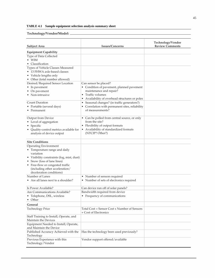
45
Subject Area Issues/Concerns Technology/Vendor Review Comments
Equipm
Technology/Vendor/Model:
ent Capability Type of Data Collected • WIM • Classification Types of Vehicle Classes Measured • 13 FHWA axle-based classes • Vehicle lengths only • Other (total number allowed) Desired/Required Sensor Location Can sensor be placed? • In pavement • Condition of pavement, planned pavement
maintenance and repair?
• On pavement • Traffic volumes • Non-intrusive • Availability of overhead structures or poles
Count Duration • Seasonal changes? (in traffic generators?) • Portable (several days) • Correlation with permanent sites, reliability
of measurements?
• Permanent
Output from Device • Level of aggregation
• Can be polled from central source, or only from the site?
• Specific • Flexibility of output formats • Quality-control metrics available for
analysis of device output • Availability of standardized formats
(NTCIP? Other?)
Site Conditions Operating Environment • Temperature range and daily
variation
• Visibility constraints (fog, mist, dust) • Snow (loss of lane lines) • Free-flow or congested traffic
(including other acceleration/ deceleration conditions)
Number of Lanes • Are all lanes next to a shoulder?
• Number of sensors required
• Number of sets of electronics required
Is Power Available? Can device run off of solar panels? Are Communications Available? • Telephone, DSL, wireless
Bandwidth required from device
• Other • Frequency of communications
General Technology Price Total Cost = Sensor Cost x Number of Sensors
+ Cost of Electronics
Staff Training to Install, Operate, and Maintain the Devices
Equipment Needed to Install, Operate, and Maintain the Device
Published Accuracy Achieved with the Technology
Has the technology been used previously?
Previous Experience with this Technology/Vendor
Vendor support offered/available
TABLE 4.1 Sample equipment selection analysis summary sheet
46
CHAPTER 5
BEST PRACTICES FOR EQUIPMENT USE
The collection of traffic load data required by the pave-ment design software is just one of a variety of traffic datacollection tasks that highway agencies must perform. Thetraffic load data collection effort cannot be done as an inde-pendent activity. It must be performed within the context ofthe entire traffic data collection effort undertaken by a high-way agency.
Determination of what equipment to purchase and how toinstall, calibrate, and maintain it, as well as what data to col-lect, how equipment and staffing resources are efficientlyused to collect it, and how the collected data are manipulated,stored, and reported once they are available, must be donewithin the context of the entire agency’s traffic data needs.Separation of the pavement design needs from the other traf-fic data needs leads to considerable inefficiency in traffic datacollection. Therefore, a need for good data practices appliesthroughout the agency’s traffic data collection program.
In general, good data collection practice can be summa-rized as nine basic steps:
1. Identify user requirements and develop an implemen-tation plan.
2. Determine location and system requirements.3. Determine site design life and accuracy necessary to
support the end user.4. Budget the resources necessary to support the selected
site design life and accuracy requirements.5. Develop and maintain a thorough quality assurance and
performance measurement program.6. Purchase the WIM or classification equipment with a
warranty.7. Manage the equipment installation.8. Calibrate and maintain calibration of equipment.9. Conduct preventive and corrective maintenance at the
data collection sites.
It is important to remember that good traffic data collec-tion practice requires the agency to also consider the impacton data collection of other traffic data needs. This sectionexpands on the traffic data collection and equipment needsdiscussed elsewhere in the report by explaining how pave-ment design data needs fit together with other agency needs.
5.1 IDENTIFY USER REQUIREMENTS
The pavement design process requires an accurate estimateof the number of heavy vehicles projected to use the roadwaylane being designed and the number, type, and weight distri-bution of the axles on those trucks. These data will comefrom a combination of project-specific counts and the sum-mary tables developed from the general truck counting andweighing program performed by the state highway agency.
The level of reliability desired by pavement design engi-neers (and the budget available to them for data collection)will result in their selection of the level of data collection per-formed for pavement design projects. The level will definethe amount of truck volume and weight data collected specif-ically to meet the needs of pavement design efforts. Theseneeds will become requests to collect specific data that aresent to the traffic data collection section of an agency.
Traffic data collection units will need to develop mecha-nisms that allow them to efficiently respond to both these spe-cific requests (which will vary from request to request) and theneed to collect the more general data that are used to create thesummary statistics and tables used when project-specific dataare not required or cannot be affordably collected.
To create a cost-effective data collection program, bothof the above needs must be efficiently coordinated with theother truck volume and weight data needs of the highwayagency. Collecting the data needed for general summarytables is part of routine data collection programs, and direc-tions for this are included in the FHWA’s Traffic Monitor-ing Guide, Sections 4 and 5. Responding efficiently to theneed for project-specific counts is a more difficult under-taking. Often it can most effectively be accomplished by set-ting up one or more meetings during each year between traf-fic data collection staff and pavement design staff to discussroadway sections that will most likely be the subject of newpavement designs in the next year or two. These sections willrequire truck traffic data collection, and a 1- to 2-year time-frame should allow efficient scheduling of the data collec-tion effort.
Scheduling this meeting (or meetings) to take place prior tothe development of each year’s traffic data collection programallows data collection staff to efficiently schedule their datacollection resources. This significantly decreases the cost ofdata collection efforts, and this scheduling efficiency more
47
than makes up for any “extra” counts that are taken but notactually used because expected pavement projects are delayed.
Data collection staff have the responsibility of coordinat-ing the needs of different users. A key to this function isknowing where flexibility exists in the collection and report-ing of data. In a simple example, if two users request the samedata for the same road but for road segments one-half mileapart, the data collection staff need to be able to determine ifthose two data collection requests can be met by a singlecount, halving the number of counts that need to be taken.
Where flexibility exists is a function of the roadway char-acteristics and the uses of the data. If the road is a rural high-way with limited activity, the two requests can likely be metwith one count. If a major freeway interchange occurs betweenthe two locations, it is unlikely that the two counts can becombined. Still, the same data collection crew will probablycollect both counts, and by collecting both counts in the sametrip at least the travel time and cost associated with the datacollection can be halved.
Traditionally, this type of coordination has been difficult toperform because pavement project selection processes werenot done early enough to fit into traffic data collection sched-ules. However, most states now operate pavement manage-ment systems that identify roadway sections in need of repairor rehabilitation in the near future. These program outputs canbe used to create a short list of projects that are likely to occurin the next 2 years. The state’s transportation improvementplan (TIP) may also provide such a list. If the actual pavementdesign list is not available when the traffic data collection pro-gram needs to be developed, this slightly larger list can be usedas a surrogate for the actual list. It may require a minor increasein the number of pavement design counts that need to be col-lected, but the slight increase in counts is more than offset bythe decrease in cost per count due not only to the coordinationefforts, but also to the more timely manner in which data canbe made available to the pavement design team.
Implementation of the recommendation to enhance thecommunication and coordination of pavement design engi-neers and traffic data collectors is more of an administrativeand institutional problem than a technical problem. If anagency succeeds, four positive changes should take place:
• The availability of traffic load data for pavement designpurposes should improve.
• The cost of collecting traffic load data for pavementdesign should decline.
• Data quality should improve as more staff review anduse the data collected.
• Internal support for traffic data collection activitiesshould improve as the users of the data improve theirunderstanding of the value and limitations of the trafficdata they are receiving.
The keys to all of these improvements are (1) achieving ahigh level of communication between pavement design engi-
neers and traffic data collectors and (2) combining that com-munication with strong advance planning. Both pavementdesign engineers and traffic data collectors obtain consider-able benefits from improving communications. Well-run traf-fic counting programs invariably have strong connections totheir users, and the pavement design section is a very impor-tant user group.
5.2 DETERMINE SITE LOCATION AND SYSTEM REQUIREMENTS
As noted in the example in the previous section, a keycomponent of the data collection process is understandingwhat, where, and why data are being collected. Understand-ing these factors is necessary for determining exactly what,when, and how data need to be collected and for selecting theequipment to be used.
Traffic data are collected from a given location eitherbecause data from that point are important to a specific designor project, or because data from that location are needed tohelp develop a default or average value that can be used atmany sites where site-specific information cannot be afford-ably collected. The first of these count efforts is generallyreferred to as “project counts.” These generally are data col-lected (1) to describe the current traffic stream crossing thedesign lane for a project and (2) to serve as a baseline uponwhich to forecast the future traffic stream. The second datacollection effort is often thought of as planning counts, whichare performed as part of general agency data collection efforts.While also meeting general agency needs, these data areused to compute the Level 2 and Level 3 load-spectradefaults1 used by the pavement design software. These countsinclude WIM efforts used to compute truck weight road group(TWRG2) axle-load distributions, and continuous classifica-tion counts are used to determine seasonal truck volume andother truck traffic patterns. Some flexibility exists in the col-lection of both of these types of data.
Ideally, project-specific counts are taken at the project site,as this provides the most reliable estimate of current trafficcrossing the design pavement. However, the actual data col-lection effort can be moved upstream or downstream fromthe project location if the project location is not conducive toaccurate traffic data collection or if other circumstances war-rant such a move. One good reason to move a project-specificcount is that the pavement at the project site is in such poorcondition that the available traffic sensors will not work accu-rately. In general, having accurate, representative data is moreimportant than having data from the exact site of the pave-ment project.
1 Level 2 load-spectra defaults are those axle weight distributions used when site-specific data for a project site are not available, but when the site can be identified witha regional average. (Level 2 is the regional average.) Level 3 represents the statewideaverage and is used only when no better information is available for a pavement design.
2 TWRGs are groups of roads that have trucks with similar loading conditions. Asample of vehicle weights is collected and used to represent the axle load distributionfor all roads that belong to that group when site-specific load information is not available.
48
If the count is moved, it should be placed so that truck traf-fic being measured is as closely related to the actual projecttraffic as possible. If the project location, for example, is onI-80 in Wyoming, a valid data collection location could be sev-eral miles away. However, if the project location is on I-95 inNew Jersey, the count most likely needs to be taken withinthe same set of interchanges as the pavement project.
Selecting data collection locations for pavement designpurposes can also be affected by the need to coordinate withother data collection needs. A highway agency may be will-ing to accept some minor error in the traffic loading estimatein order to reduce the total counting burden of the state, andthe agency thus may choose to use an existing count that isslightly removed from the project location rather than go tothe expense of collecting newer, more precise information.
Even broader flexibility is available to highway agenciesas they select those locations where data are collected tocompute the TWRGs. The primary goal of the TWRG is toprovide an accurate measure of average conditions for agiven set of roads. Given the lack of weight data available tomost highway agencies and the cost and difficulty of col-lecting accurate weight data, most agencies know relativelylittle about the vehicle weights present on specific roads.Thus, considerable latitude is available in the selection ofdata collection sites that are included in the TWRG compu-tations because most agencies have little information uponwhich to judge alternative locations and any valid data arebetter than no data.
The first criterion of TWRG formation is that the sites besimilar in characteristics to the other roads they represent.(For example, the shape of the axle load distribution associ-ated with FHWA Class 9 trucks should be similar at all siteswithin the TWRG.) The second criterion for data collectionis that the sites selected be conducive to accurate weight datacollection. This means that the pavement should be in goodcondition. It should be flat, with no ruts. The pavement shouldbe strong enough to support weight sensors effectively underwhatever environmental conditions are present when weightdata are being collected.
It is recommended that, at least initially, data collection forTWRG development be oriented toward sites at which accu-rate data can most confidently be collected. As budgets permit,the weight data collection program should then be expandedor moved to other locations around the state (where WIMequipment can be accurately operated) in order to gain a morecomplete picture of truck weights around the state.
5.3 DETERMINE DESIGN LIFE AND ACCURACY REQUIREMENTS
Another key to efficient expenditure of data collectionresources is to match the design life of equipment to the lifeof pavement and select the equipment accordingly. It is rarelya wise decision to select a WIM sensor that is expected to out-live the pavement in which it is placed. Few WIM installa-
tions can be removed intact from the roadway and reused.(This does not include technologies such as bending plates,where the sensor itself can be removed, but the frames intowhich the plates are set are not removable.) Thus, it makeslittle sense to design a 5-year WIM site for a pavement thatwill be repaved in 3 years.
For WIM data collection, site failure is often the result offailure of the pavement condition around the site, not just thefailure of sensors themselves. Thus, site design life is a func-tion of the fatigue life of the sensor itself, the installationquality of the sensor, the initial site condition and design, andthe expected wear on the pavement.
Sensor fatigue life is usually a function of the sensordesign and the traffic loadings. Vendors normally warrantytheir sensors for a specified period, and obtaining a warrantyis itself a recommended best practice. Sensors with longerfatigue lives are usually more expensive than shorter-livedsensors.
However, many WIM systems become inoperable notbecause of sensor failure, but because of the failure of pave-ment around them. This includes both when the pavement/sensor bond fails and when pavement deterioration such asrutting exposes the sensor to impact loads (e.g., snowplowblades) that cause catastrophic failure. A primary cause ofpremature pavement/sensor bond failure is poor initial instal-lation quality. This includes such errors as poor mixing ofadhesives, poorly cleaned or dried pavement cuts, incompat-ibility of sealants and pavement, and inappropriate tempera-ture conditions.
Site condition and site design are key areas that successfulprograms examine as part of WIM site design and imple-mentation. Where remaining pavement life is only modest,strong consideration should be given to rehabilitating thepavement prior to WIM sensor installation if an extendeddesign life for the site is desired. Unfortunately, pavementrehabilitation is a costly addition to WIM installation. How-ever, if a scale site is expected to have a long life, life-cyclecosts are far lower if the pavement at the site is rehabilitatedprior to initial sensor installation.
In many cases, highway agencies have found it to be awise investment to build 300-foot concrete pavement sec-tions into which WIM scales are placed. This gives agenciessmooth, strong, maintainable platforms in which to place sen-sors. Strong concrete pavements generally do not changestructural strength with changing temperatures and tend todeteriorate slowly. Thus, strong concrete pavements are gen-erally considered to be good locations for scale sensors. Apavement with high-durability characteristics provides for along design life and low maintenance costs for the scale sys-tem. (However, it is important to note that the pavement mustbe smooth as well as durable to be good for vehicle weighing.)
Not all WIM installations are intended to last many years.In many cases, an agency only wishes to collect data for a yearor two at a location before moving the agency’s scarce WIMresources to another location. In such a situation, the design
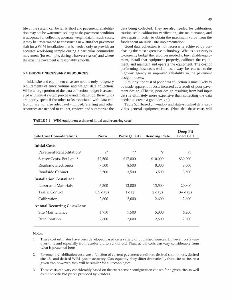
49
life of the system can be fairly short and pavement rehabilita-tion may not be warranted, so long as the pavement conditionis adequate for collecting accurate weight data. In such cases,it may be unwarranted to construct a new 300-foot pavementslab for a WIM installation that is needed only to provide anaccurate week-long sample during a particular commoditymovement (for example, during a harvest season) and wherethe existing pavement is reasonably smooth.
5.4 BUDGET NECESSARY RESOURCES
Initial site and equipment costs are not the only budgetaryrequirements of truck volume and weight data collection.While a large portion of the data collection budget is associ-ated with initial system purchase and installation, these fundsare poorly spent if the other tasks associated with data col-lection are not also adequately funded. Staffing and otherresources are needed to collect, review, and summarize the
data being collected. They are also needed for calibration,routine scale calibration verification, site maintenance, andsite repair in order to obtain the maximum value from thefunds spent on initial site implementation.
Good data collection is not necessarily achieved by pur-chasing the most expensive technology. What is necessary isto correctly budget the resources needed to buy reliable equip-ment, install that equipment properly, calibrate the equip-ment, and maintain and operate the equipment. The cost ofperforming these tasks will almost always be returned to thehighway agency in improved reliability in the pavementdesign process.
Similarly, the cost of poor data collection is most likely tobe made apparent in costs incurred as a result of poor pave-ment design. (That is, poor design resulting from bad inputdata is ultimately more expensive than collecting the dataneeded to create a good design.)
Table 5.1 (based on vendor- and state-supplied data) pro-vides general equipment costs. (Note that these costs will
TABLE 5.1 WIM equipment estimated initial and recurring costs1
Site Cost Considerations Piezo Piezo Quartz Bending Plate Deep Pit Load Cell
Initial Costs
Pavement Rehabilitation2 ?? ?? ?? ??
Sensor Costs, Per Lane3 $2,500 $17,000 $10,000 $39,000
Roadside Electronics 7,500 8,500 8,000 8,000
Roadside Cabinet 3,500 3,500 3,500 3,500
Installation Costs/Lane
Labor and Materials 6,500 12,000 13,500 20,800
Traffic Control 0.5 days 1 day 2 days 3+ days
Calibration 2,600 2,600 2,600 2,600
Annual Recurring Costs/Lane
Site Maintenance 4,750 7,500 5,300 6,200
Recalibration 2,600 2,600 2,600 2,600
Notes:
1.
2.
3.
These cost estimates have been developed based on a variety of published sources. However, costs vary over time and especially from vendor bid to vendor bid. Thus, actual costs can vary considerably from what is presented here.
Pavement rehabilitation costs are a function of current pavement condition, desired smoothness, desired site life, and desired WIM system accuracy. Consequently, they differ dramatically from site to site. At a given site, however, they will be similar for all technologies.
These costs can vary considerably based on the exact sensor configuration chosen for a given site, as well as the specific bid prices provided by vendors.
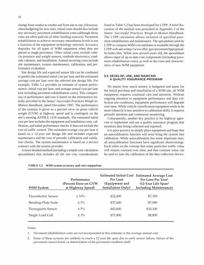
50
change from vendor to vendor and from site to site.) However,when budgeting for new sites, initial costs should also includeany necessary pavement rehabilitation costs (although thosecosts are often paid out of other funding sources). Pavementrehabilitation to achieve necessary smoothness levels is nota function of the equipment technology selected. Accuracydegrades for all types of WIM equipment when they areplaced in rough pavement. Other initial costs include vehi-cle presence and weight sensors, roadside electronics, road-side cabinets, and installation. Annual recurring costs includesite maintenance, system maintenance, calibration, and per-formance evaluation.
Site design life and expected sensor life can be combinedto predict the estimated initial cost per lane and the estimatedaverage cost per lane over the selected site design life. Forexample, Table 5.2 provides an estimate of system perfor-mance, initial cost per lane, and average annual cost per lane(not including pavement rehabilitation costs). This compari-son of performance and cost is based on the information ini-tially provided in the States’ Successful Practices Weigh-in-Motion Handbook, dated December 1997. The performanceof the systems is given as a percent error on gross vehicleweight (GVW) at highway speed and is contingent on thesite’s meeting ASTM E 1318 standards. The estimated initialcost per lane includes the equipment and installation costs, cal-ibration, and initial performance checks. It does not include thecost of traffic control. The estimated average cost per lane isbased on a 12-year site design life and includes expectedmaintenance and the cost of periodic calibration and valida-tion checks. The system maintenance is based on a servicecontract with the system provider.
A more detailed method (including a simple cost-calculationspreadsheet) that includes all the site cost considerations
listed in Table 5.2 has been developed for LTPP. A brief dis-cussion of the method was presented in Appendix 2 of theStates’ Successful Practices Weigh-in-Motion Handbook.The LTPP calculation allows inclusion of specified pave-ment rehabilitation and maintenance. The spreadsheet used byLTPP to compute WIM cost estimates is available through theLTPP web site at http://www.tfhrc.gov/pavement/ltpp/spstraf-fic/index.htm. While now several years old, the spreadsheetallows input of up-to-date cost components (including pave-ment rehabilitation costs), as well as the costs and character-istics of new WIM equipment.
5.5 DEVELOP, USE, AND MAINTAIN A QUALITY ASSURANCE PROGRAM
No matter how much money is budgeted and spent forthe initial purchase and installation of a WIM site, all WIMequipment requires continual care and attention. Withoutongoing attention to equipment performance and data col-lection site conditions, equipment performance will degradeover time. While vehicle classification equipment tends to bemore robust (it is less sensitive to calibration drift), it requiresperiodic attention and continuous monitoring.
Consequently, another key practice is for highway agen-cies to implement and use a quality assurance program thatmonitors data being collected and reported.
It is poor practice to simply place equipment and hope thatan autocalibration function will soon bring the system intocalibration. While autocalibration has some important uses,all autocalibration functions have significant shortcomings.Each relies on the concept that some particular traffic valuewill remain constant over time, and that constant value canbe used to tune the calibration of the data collection device.
TABLE 5.2 WIM system accuracy and cost comparison
WIM System
Performance (Percent Error on GVW
at Highway Speed)
Estimated Initial Cost Per Lane
(Equipment and Installation Only)1
Estimated Average Cost Per Lane Per Year1 (12-Year Life Span2
Including Maintenance)
Piezoelectric Sensor ± 10% $22,600 $7,350
Bending-Plate Scale ± 5% $37,600 $7,900
Piezoquartz Sensor ± 5% $43,600 $10,100
Single Load Cell ± 3% $73,900 $8,800
Notes:
1.
2.
Pavement rehabilitation costs are not incorporated in this estimate or the average annual cost.
Some of these systems are unlikely to reach a 12-year life span due to early sensor failure, failure of the pavement/sensor bond, or deterioration of the pavement condition itself.
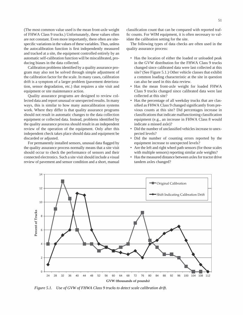
51
(The most common value used is the mean front-axle weightof FHWA Class 9 trucks.) Unfortunately, these values oftenare not constant. Even more importantly, there often are site-specific variations in the values of these variables. Thus, unlessthe autocalibration function is first independently measuredand tracked at a site, the equipment controlled entirely by anautomatic self-calibration function will be miscalibrated, pro-ducing biases in the data collected.
Calibration problems identified by a quality assurance pro-gram may also not be solved through simple adjustment ofthe calibration factor for the scale. In many cases, calibrationdrift is a symptom of a larger problem (pavement deteriora-tion, sensor degradation, etc.) that requires a site visit andequipment or site maintenance action.
Quality assurance programs are designed to review col-lected data and report unusual or unexpected results. In manyways, this is similar to how many autocalibration systemswork. Where they differ is that quality assurance programsshould not result in automatic changes to the data collectionequipment or collected data. Instead, problems identified bythe quality assurance process should result in an independentreview of the operation of the equipment. Only after thisindependent check takes place should data and equipment bediscarded or adjusted.
For permanently installed sensors, unusual data flagged bythe quality assurance process normally means that a site visitshould occur to check the performance of sensors and theirconnected electronics. Such a site visit should include a visualreview of pavement and sensor condition and a short, manual
classification count that can be compared with reported traf-fic counts. For WIM equipment, it is often necessary to val-idate the calibration setting for the site.
The following types of data checks are often used in thequality assurance process:
• Has the location of either the loaded or unloaded peakin the GVW distribution for the FHWA Class 9 truckschanged since calibrated data were last collected at thissite? (See Figure 5.1.) Other vehicle classes that exhibita common loading characteristic at the site in questioncan also be used in this data review.
• Has the mean front-axle weight for loaded FHWAClass 9 trucks changed since calibrated data were lastcollected at this site?
• Has the percentage of all weekday trucks that are clas-sified as FHWA Class 9 changed significantly from pre-vious counts at this site? Did percentages increase inclassifications that indicate malfunctioning classificationequipment (e.g., an increase in FHWA Class 8 wouldindicate a missed axle)?
• Did the number of unclassified vehicles increase to unex-pected levels?
• Did the number of counting errors reported by theequipment increase to unexpected levels?
• Are the left and right wheel path sensors (for those scaleswith multiple sensors) reporting similar axle weights?
• Has the measured distance between axles for tractor drivetandem axles changed?
0
2
4
6
8
10
12
14
24 28 32 36 40 44 48 52 56 60 64 68 72 76 80 84 88 92 96 100 104 108 112
GVW (thousands of pounds)
Per
cen
t of
Tru
cks
Original Calibration
Shift Indicating Calibration Drift
Figure 5.1. Use of GVW of FHWA Class 9 trucks to detect scale calibration drift.
52
• Is the total number of vehicles counted within expectedranges? (Note that the range used should be fairly largebecause truck volumes in particular can vary significantlyfrom day to day.)
• Are there any unusual time-of-day traffic patterns thatwould indicate the potential for some type of counterfailure or inappropriate counter setting? (For example,does the volume at 1:00 a.m. exceed the volume presentat 1:00 p.m.?)
• Are hours of data missing from the dataset?• Have the scale’s diagnostics reported any problems?
Most of these checks assume that a trusted dataset existsagainst which new data can be compared in order to deter-mine the presence of unusual data. For permanent data col-lection sites, the best place to get these trusted datasets isimmediately after the site is first installed and calibrated. Theinitial calibration effort should ensure that the site is workingcorrectly, that the vehicles crossing the sensors are being cor-rectly counted and classified, and that the weights are accu-rate. Data collected immediately after calibration should thenserve as the initial trusted dataset.
If traffic patterns change over time (and the validity ofthese changes is independently confirmed), additional trusteddata patterns can be developed, stored, and used as part of thequality assurance process.
For short-duration counts, it is important that data collec-tion crews that set equipment confirm the equipment’s properoperation at the outset before leaving the site and then recon-firm the equipment’s proper operation prior to picking up thesensors at the end of the count. (That is, the crews should per-form a consistent, routine check to ensure that the counter iscorrectly counting and classifying vehicles each time it isplaced.) Office-based reviews can then compare the col-lected data against the short-duration counts made to confirmequipment operation, as well as against earlier (historical)counts made at that site or at nearby sites on that roadway.
In addition to these basic data checks, a number of addi-tional routines are often provided by equipment vendors ordeveloped by individual agencies. These should be reviewed,tested, and used whenever they offer cost-effective improve-ments to available procedures.
The key to any quality assurance program is that the rou-tines available are tested and used. This requires resourcesand effort, but results in substantial improvement in the qual-ity of data collected and supplied to users. Over time, qual-ity assurance practices will help identify poor equipment andpoor data collection practices, which can then be discardedor modified as appropriate. These practices also will helpagencies improve their knowledge of traffic patterns in thestate, which is a major benefit to an agency.
Wherever possible, quality assurance tests should be auto-mated. However, the automated tests should primarily belimited to
• Creating easy-to-use data summaries,• Flagging questionable data, and• Removing poor data after their quality has been con-
firmed to be poor by qualified staff review.
Staff review of these summaries and the performance ofindependent reviews of irregular data collection results shouldstill be done for all collected data. As noted earlier, traffic canvary considerably from location to location, and knowledge ofsite-specific traffic patterns and independent review of ques-tionable data are keys to successful quality assurance programs.
5.6 PURCHASE EQUIPMENT WITH A WARRANTY
When purchasing equipment, it is good practice to obtaina warranty on the life of that equipment. The warranty shouldspecify the expected life of the sensor given specific uses ofthat sensor. For example, a 5-year warranty on bending-plateweigh pads might be specified given a lane volume of lessthan 5,000 trucks per day.
Warranties provide agencies insurance against poor manu-facturing quality control and also provide incentives to ven-dors and manufacturers to improve the quality of their equip-ment. Warranties are not free, but limit the cost of equipmentreplacement. For a vendor, the added revenue obtained inreturn for a warranty becomes profit, so long as the equipmentperforms as specified. However, if equipment fails prema-turely, a significant loss to the vendor occurs. This approachprovides a significant incentive to correctly predict the lifespan of sensors and other equipment.
Warranties of overall system performance have been suc-cessfully used by some states. These warranties extend pro-tection beyond the sensor and accompanying electronics to thequality of the data produced by the data collection systems.These warranties are only effective when the highway agencycan supply appropriate site conditions (e.g., smooth enoughpavement) to make the warranty valid and when a mechanismto monitor compliance with the warranty is in place.
For example, with WIM equipment, it is likely that theequipment vendor subject to this type of warranty requirementwill require the site to meet the site specifications defined inASTM E 1318 specifications. While these conditions maybe met immediately after sensor installation, it may be nearlyimpossible to meet these conditions after two additionalyears of pavement deterioration. Such difficulties can makeperformance warranties unenforceable.
This example points out that if a highway agency choosesto require data quality warranties from outside vendors, itis necessary to set up a quality assurance program that canbe used both to detect equipment that needs repair and todetermine when the site conditions no longer meet warrantyspecifications. The specifications developed for LTPP SPS
53
WIM data collection are a good first step toward this typeof program.3
5.7 MANAGE EQUIPMENT INSTALLATION
Proper installation of sensors is key to both performanceand life span, regardless of the technology involved.
To ensure the quality of any given installation, it is goodpractice to have at least one agency representative and onevendor representative oversee the sensor installation processat permanent sites. This ensures that both the state’s and thevendor’s requirements are met during the installation process.This is particularly important when warranties are used toensure system performance, in that it ensures that both par-ties are satisfied with the initial site conditions and installa-tion. (For WIM performance warranties, site conditions mustusually match ASTM E 1318 site condition specifications.These site conditions should be verified by both parties whenthe site is first selected, well prior to the beginning of theinstallation process.)
Installation of sensors does not just involve placement.For permanently mounted sensors, installation also involves(among other items) placement of conduit for lead wires,placement and design of junction boxes, design and place-ment of cabinets that hold data collection electronics, andprovision of environmental protection (lighting and electri-cal surge protection, moisture protection, temperature con-trols, defenses against insect and rodent infestation) for theentire system.
Poor installation of any features can lead to early systemfailure and significant increases in both sensor downtime andmaintenance and repair costs.
Good practice for equipment installation includes choos-ing good equipment and sensor locations in the first place.For intrusive sensors, this means placing them in or on pave-ment that is in good condition and likely to last well past thedesign life of the sensors being installed. For both intrusiveand non-intrusive sensors, it means understanding the envi-ronmental conditions that occur at a site and designing sen-sor installations so that sensors are protected as much as pos-sible from environmental effects on system performance. (Forexample, video cameras need to be placed so that glare andother lighting problems are minimized and so that the cam-eras are protected from rain, snow, and spray generated byvehicles. Similarly, intrusive sensors need to be protected frommoisture intrusion, with particular attention paid to in-pave-ment wiring when freeze-thaw conditions exist.)
A variety of techniques exist for protection of sensors fromenvironmental conditions. Good management practice is todocument those practices that are successful (for future useby new staff within the agency) and to share those successeswith other agencies.
5.8 CALIBRATE AND MAINTAIN CALIBRATION OF EQUIPMENT
Installation of equipment should not be considered com-plete until that equipment has been calibrated and acceptancetesting of the device in that location has been completed.Both WIM and vehicle classification devices require calibra-tion, although WIM calibration is far more complex and dif-ficult than vehicle classification.
5.8.1 Initial Calibration
A number of procedures for calibrating WIM scales exist.Appendix 5-A in the 2001 FHWA Traffic Monitoring Guide4
provides a reasonably complete description of the currentstate-of-the-art in WIM system calibration. Some materialfrom this appendix is reprinted below. In addition, ASTM5
and the FHWA’s Long Term Pavement Performance Project6
have recommended the use of two test trucks of knownweight but different vehicle characteristics (different classi-fications and/or suspension types) for performing WIM scalecalibration.
The two-test-truck calibration technique consists of obtain-ing static weights for two distinctly different vehicles and thenrepeatedly driving those vehicles over the WIM scale. Scalecalibration factors are then adjusted to minimize the meanerror obtained when comparing static and dynamic weights.(Both the ASTM and LTPP documents provide step-by-stepdirections for calibrating scales using this technique.) Ideally,during the calibration effort, the two test trucks should bedriven over the WIM scale at a variety of speeds and undervaried pavement temperature conditions in order to ensurethat the scale operates correctly under all expected operat-ing conditions.
The use of two calibration vehicles is specifically designedto limit calibration biases that can be caused by the use of asingle test vehicle. Biased calibration when using a single testtruck comes from the fact that every truck has its own uniquedynamic interaction with a given road profile given a specificload. Calibration of a scale to a single vehicle’s dynamic per-formance (motion) is acceptable when the motion of thatvehicle is representative of the traffic stream. Unfortunately,it is extremely difficult to determine if a given test truck isrepresentative of the traffic stream, and consequently use ofa single vehicle can cause a calibration bias that forces thescale to weigh most vehicles inaccurately.
The source of this calibration bias can be explained withtwo figures. Figure 5.2 illustrates how the force applied by a
3 http://www.tfhrc.gov/pavement/ltpp/spstraffic/index.htm (active as of June 20, 2003).
4 http://www.fhwa.dot.gov/ohim/tmguide/index.htm (active as of June 20, 2003).5 American Society of Testing Materials, Annual Book of ASTM Standards 2000, Sec-
tion 4, Construction, Volume 04.03, Designation: E 1318-02—Standard Specificationfor Highway Weigh-In-Motion (WIM) Systems with User Requirements and TestMethod, ASTM.
6 Long Term Pavement Performance Program Protocol for Calibrating Traffic DataCollection Equipment, April 1998 (with 5/10/98 revisions). http://www.tfhrc.gov/pave-ment/ltpp/pdf/trfcal.pdf (active as of June 20, 2003).
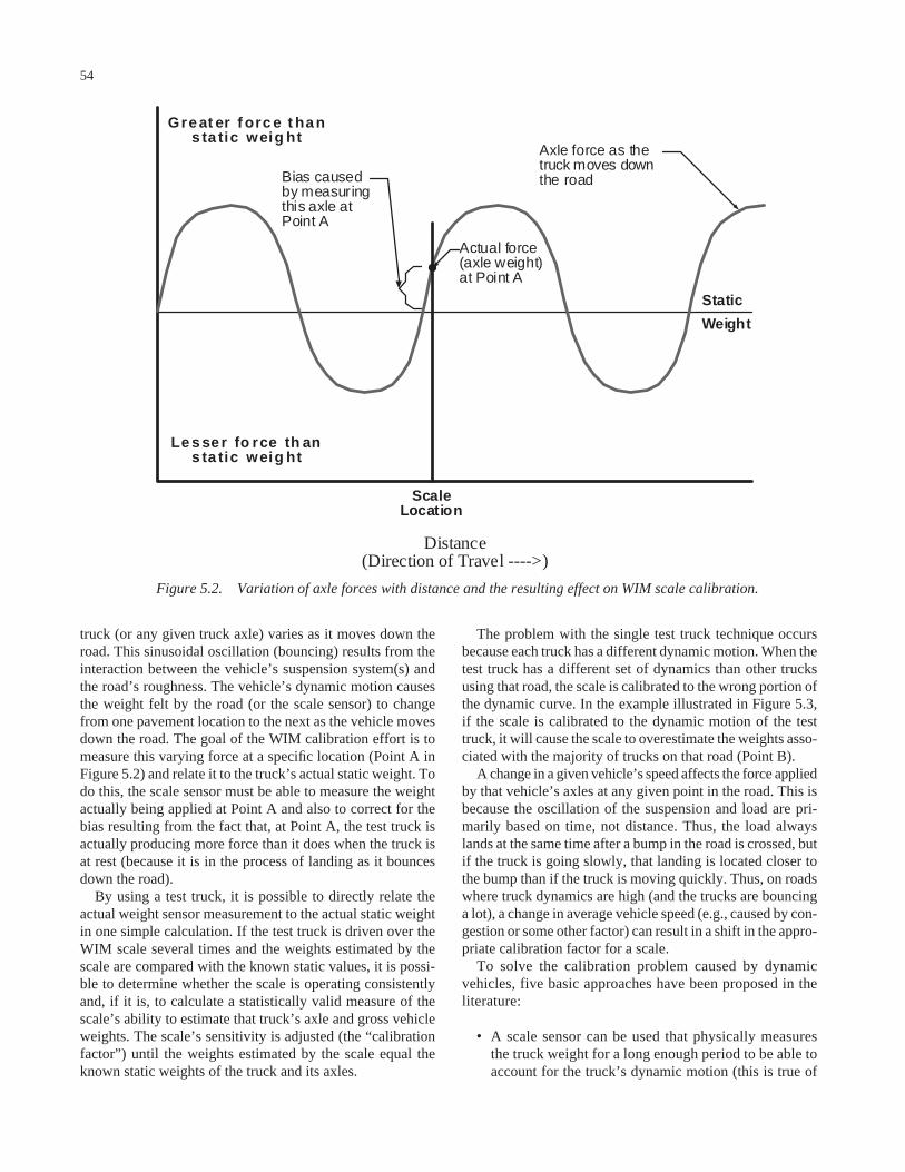
54
truck (or any given truck axle) varies as it moves down theroad. This sinusoidal oscillation (bouncing) results from theinteraction between the vehicle’s suspension system(s) andthe road’s roughness. The vehicle’s dynamic motion causesthe weight felt by the road (or the scale sensor) to changefrom one pavement location to the next as the vehicle movesdown the road. The goal of the WIM calibration effort is tomeasure this varying force at a specific location (Point A inFigure 5.2) and relate it to the truck’s actual static weight. Todo this, the scale sensor must be able to measure the weightactually being applied at Point A and also to correct for thebias resulting from the fact that, at Point A, the test truck isactually producing more force than it does when the truck isat rest (because it is in the process of landing as it bouncesdown the road).
By using a test truck, it is possible to directly relate theactual weight sensor measurement to the actual static weightin one simple calculation. If the test truck is driven over theWIM scale several times and the weights estimated by thescale are compared with the known static values, it is possi-ble to determine whether the scale is operating consistentlyand, if it is, to calculate a statistically valid measure of thescale’s ability to estimate that truck’s axle and gross vehicleweights. The scale’s sensitivity is adjusted (the “calibrationfactor”) until the weights estimated by the scale equal theknown static weights of the truck and its axles.
The problem with the single test truck technique occursbecause each truck has a different dynamic motion. When thetest truck has a different set of dynamics than other trucksusing that road, the scale is calibrated to the wrong portion ofthe dynamic curve. In the example illustrated in Figure 5.3,if the scale is calibrated to the dynamic motion of the testtruck, it will cause the scale to overestimate the weights asso-ciated with the majority of trucks on that road (Point B).
A change in a given vehicle’s speed affects the force appliedby that vehicle’s axles at any given point in the road. This isbecause the oscillation of the suspension and load are pri-marily based on time, not distance. Thus, the load alwayslands at the same time after a bump in the road is crossed, butif the truck is going slowly, that landing is located closer tothe bump than if the truck is moving quickly. Thus, on roadswhere truck dynamics are high (and the trucks are bouncinga lot), a change in average vehicle speed (e.g., caused by con-gestion or some other factor) can result in a shift in the appro-priate calibration factor for a scale.
To solve the calibration problem caused by dynamicvehicles, five basic approaches have been proposed in theliterature:
• A scale sensor can be used that physically measuresthe truck weight for a long enough period to be able toaccount for the truck’s dynamic motion (this is true of
Figure 5.2. Variation of axle forces with distance and the resulting effect on WIM scale calibration.
Axle force as thetruck moves downthe road
Actual force(axle weight)at Point A
ScaleLocation
Bias causedby measuringthis axle atPoint A
Distance(Direction of Travel ---->)
Static
Weight
Le s se r fo rce th ans ta tic weig ht
Gre at er f orc e t ha ns ta tic weig ht
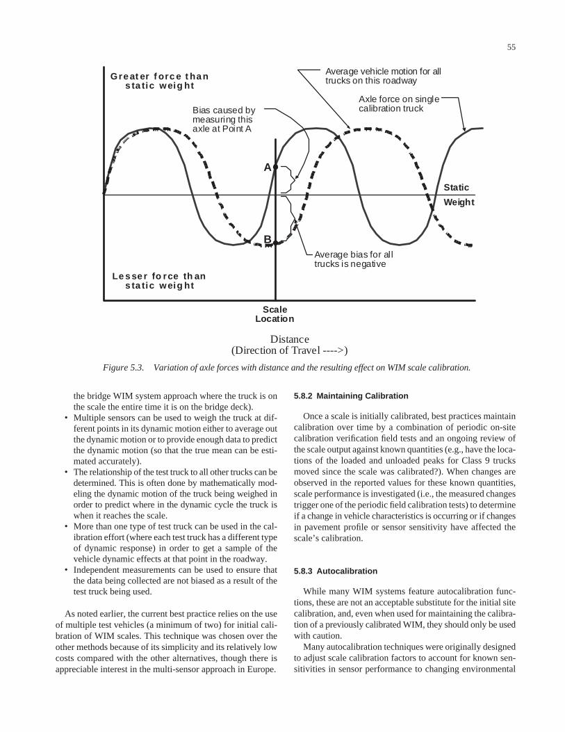
55
the bridge WIM system approach where the truck is onthe scale the entire time it is on the bridge deck).
• Multiple sensors can be used to weigh the truck at dif-ferent points in its dynamic motion either to average outthe dynamic motion or to provide enough data to predictthe dynamic motion (so that the true mean can be esti-mated accurately).
• The relationship of the test truck to all other trucks can bedetermined. This is often done by mathematically mod-eling the dynamic motion of the truck being weighed inorder to predict where in the dynamic cycle the truck iswhen it reaches the scale.
• More than one type of test truck can be used in the cal-ibration effort (where each test truck has a different typeof dynamic response) in order to get a sample of thevehicle dynamic effects at that point in the roadway.
• Independent measurements can be used to ensure thatthe data being collected are not biased as a result of thetest truck being used.
As noted earlier, the current best practice relies on the useof multiple test vehicles (a minimum of two) for initial cali-bration of WIM scales. This technique was chosen over theother methods because of its simplicity and its relatively lowcosts compared with the other alternatives, though there isappreciable interest in the multi-sensor approach in Europe.
5.8.2 Maintaining Calibration
Once a scale is initially calibrated, best practices maintaincalibration over time by a combination of periodic on-sitecalibration verification field tests and an ongoing review ofthe scale output against known quantities (e.g., have the loca-tions of the loaded and unloaded peaks for Class 9 trucksmoved since the scale was calibrated?). When changes areobserved in the reported values for these known quantities,scale performance is investigated (i.e., the measured changestrigger one of the periodic field calibration tests) to determineif a change in vehicle characteristics is occurring or if changesin pavement profile or sensor sensitivity have affected thescale’s calibration.
5.8.3 Autocalibration
While many WIM systems feature autocalibration func-tions, these are not an acceptable substitute for the initial sitecalibration, and, even when used for maintaining the calibra-tion of a previously calibrated WIM, they should only be usedwith caution.
Many autocalibration techniques were originally designedto adjust scale calibration factors to account for known sen-sitivities in sensor performance to changing environmental
Figure 5.3. Variation of axle forces with distance and the resulting effect on WIM scale calibration.
Axle force on singlecalibration truck
Average bias for alltrucks is negative
ScaleLocation
Bias caused bymeasuring thisaxle at Point A
Distance(Direction of Travel ---->)
Static
Weight
Le s se r fo rce th ans ta tic weig ht
Gre at er f orc e t ha ns ta tic weig ht
Average vehicle motion for alltrucks on this roadway
A
B

56
conditions. Others were software adjustments developed totake into account equipment limitations. Common techniquesinclude
• Using the average front-axle weight of FHWA Class 9trucks and
• Using the average weight of specific types of vehicles(often loaded five-axle tractor semi-trailers or passen-ger cars).
Although these techniques can have considerable value,they are only useful after the conditions they are monitoringat the study site have been confirmed. In fact, tests performedby LTPP7 showed that autocalibration functions were notalways successful at maintaining calibration of environ-mentally sensitive sensors when environmental conditionswere changing rapidly. Autocalibration functions cannot beexpected to calibrate a scale accurately if key autocalibrationvalues have not been independently confirmed at that site.
Site-specific confirmation of autocalibration variables isimportant because research has shown that those key vari-ables are not as constant as thought when autocalibration forWIM was first developed. For example, while the averagefront axle weight for Class 9 vehicles at most sites stays fairlyconstant (and can be measured accurately if a large enoughsample is taken), the average front axle weight often variessignificantly from site to site across the country or even withina state. Part of this variation is due to different weight lawsand truck characteristics, part is due to different truck load-ing conditions at each site, and part is due to vehicle charac-teristics that are controlled by vehicle drivers.
Most drivers of modern tractors can change the location ofthe “king pin” (i.e., the point at which the semi-trailer con-nects to the tractor). Setting the king pin close to the cab pullsin the trailer, reducing air resistance and improving fuel effi-ciency. However, this setting also magnifies the roughness ofthe ride in the cab and increases driver discomfort. Settingthe king pin farther away from the cab smoothes the ride inthe cab but results in higher fuel consumption. When operat-ing on rough roads, drivers tend to set the king pin fartherback than when they operate on smooth roads.
If no other changes are made, simply moving the king pinsetting from its foremost position to its rearmost position canshift as much as 2,000 pounds onto or away from the front axleof a fully loaded heavy truck. This is a change of 10 to 15 per-cent. By not accounting for these fairly common fleet changesat a specific WIM scale location, similar errors can be auto-calibrated into the WIM system. In fact, LTPP has confirmedseveral cases in which autocalibration settings forced scales toadopt biased calibration factors simply because the autocali-bration setting was incorrect for a particular site.
Autocalibration is not a bad idea. However, before it canbe used even to maintain a scale’s calibration, several factorsmust be understood:
• What autocalibration procedure the scale is using,• Whether that procedure is based on assumptions that are
true for a particular site,• How that procedure complements the limitations in the
axle sensor (and sensor installation) being used, and• Whether enough vehicles being monitored as part of the
autocalibration function are crossing the sensor duringa given period to allow the calibration technique tofunction as intended.
The highway agency should also thoroughly test the actualperformance of an autocalibration system before assumingthat a vendor’s claims about its accuracy are valid. Only aftertesting has been satisfactorily completed should a state rou-tinely use autocalibration. Even then, autocalibration does noteliminate the need for a state to monitor scale output or peri-odically perform calibration verification tests in the field.
5.8.4 Calibration of Vehicle Classification Equipment
In theory, calibration of vehicle classification equipmentis not as difficult as WIM system calibration. In reality, somespecific installation problems can cause problems with clas-sifier output. Compared with WIM equipment, axle-basedvehicle classification equipment is generally less sensitive tominor variations in signal strength. However, some non-intrusive sensors can be very sensitive to input parametersand may require careful tuning of sensor performance to workcorrectly.
There are basically three issues related to the performanceof classifiers that need to be reviewed as part of the installa-tion calibration:
• Sensor configuration and layout information,• Conversion of the outputs into estimates of each passing
vehicle’s characteristics (vehicle speed, vehicle length,and distance between axles), and
• The conversion of the vehicle characteristic informationinto estimates of that vehicle’s classification.
Automated vehicle classifiers generally require input ofinformation related to the specific layout of the sensors used.For axle classifiers, this generally means the distance betweenthe two axle sensors (or two loops used for vehicle speedcomputation). For non-intrusive detectors, it may includemeasurements such as the height of the camera and angle ofview or the distance of a sensor from the roadway.
These measurements are used as input to the sensor sys-tems to convert the sensor outputs into the estimates of vehi-cle speed, length, and axle spacing, which are in turn used to
7 SPS Traffic Site Evaluation—Pilots Summary and Lessons Learned, May 2, 2002,http://www.tfhrc.gov/pavement/ltpp/reports/lessons/Lessons.pdf (active as of June 20,2003).
57
compute vehicle classification. While these outputs are the keycalibration measure, problems with the estimation of thesevalues are often a function of poor measurement of the sen-sor layout. Adjustment of these parameters may be needed tomake the classifier correctly report vehicle speed and conse-quently axle spacing or vehicle length. (Note that, dependingon the classifier technology used, other device parametersmay also require adjusting to produce correct device output.)
The accuracy of vehicle speeds should be determined bycomparing device output against independent measures ofvehicle speed collected using a calibrated radar gun or sim-ilar device. Vehicle length and axle spacing computationsshould be compared by comparing these outputs against inde-pendently collected axle spacing and vehicle length data.
Correctly classifying a vehicle requires more than an accu-rate measurement of vehicle speed and the distance betweenaxles (or overall vehicle length). The conversion of these vehi-cle characteristics into an estimate of what vehicle type isrepresented by that set of attributes is the function of the clas-sification algorithm used by the equipment. While many clas-sification errors are caused by poor sensor input, many errorsare simply the result of a classification algorithm that incor-rectly associates a given set of vehicle characteristics with thewrong class of vehicle. With axle classification, this occurs inpart because some vehicles from different classes have iden-tical axle spacings. For example, FHWA Class 2 (cars) andFHWA Class 3 (light-duty pickups) have considerable axle-spacing overlap. Many small pickups have shorter axle spac-ings than larger cars. Thus, a considerable number of errorsoccur when classifiers try to differentiate between these twoclasses of vehicles. Recreational vehicles (especially thosepulling trailers or other vehicles) are another class of vehi-cles that have axle spacings that frequently cause them to bemisclassified, even when the classifier is working.
Errors associated with poor classification must thereforebe separated into those due to poor sensor output and thoserelated to the combination of a poor classification algorithmand/or vehicle characteristics that prevent a given set of sen-sor outputs (axle number and spacing or vehicle length) fromcorrectly classifying a vehicle. Poor sensor output can be dealtwith at the time of equipment installation, set up, and calibra-tion. The other two problems must be dealt with through therigorous design and testing of the classification algorithmused by the agency and through an extensive equipmentacceptance-testing program that should be performed whena given brand or model of equipment is first selected for use.(That is, the agency needs to make sure the equipment willclassify correctly if installed properly before purchasinglarge quantities of a given device. Only once the classifier hasbeen shown to work as desired should the device be pur-chased in quantity. If, during the acceptance testing, a deviceappears to be working correctly but cannot classify specifictypes of vehicles, the agency should carefully examine theclassification algorithm being used to determine if the algo-rithm itself needs to be fixed.)
5.8.5 A Final Word on Calibration and Equipment Installation
Calibration is a key part of the initial equipment set up.However, calibration alone will not compensate for a poorlyinstalled piece of equipment. Poorly installed sensors oftenproduce inconsistent signal outputs, making calibration eitherimpossible or unstable over time, as sensor performancedeclines over time. Poor installation also leads to early sys-tem failure and significant increases in both sensor downtimeand maintenance costs. A key part of installation and cali-bration efforts is to ensure that the sensors that have beeninstalled are producing consistent signals.
5.9 CONDUCT PREVENTIVE AND CORRECTIVE MAINTENANCE
Preventive maintenance keeps equipment operating. Per-haps more importantly, preventive maintenance helps keepdata quality problems to a minimum by reducing the numberof strange axle detections that occur during early phases ofsensor and pavement failure.
Preventive maintenance includes tasks such as cleaningelectronics cabinets, replacing parts that are showing wearbut that have not yet failed, and even doing minor pavementrepairs that are designed to improve pavement smoothnessand life such as crack sealing on approaches to sensors.
Corrective maintenance is the process of bringing a sensorthat is not performing properly back into correct operation.Corrective maintenance can include physical changes to sen-sors or pavement (e.g., sealing cracks in the pavement orrepairing the bond between sensors and pavement), replace-ment of failing or failed electrical components, or simplyadjustments to sensor calibrations used for computing speed,weights, or overall vehicle length.
Proper, timely maintenance increases sensor life, improvesdata quality, and decreases overall system life-cycle cost.States that have snow and ice conditions need to consider theadded maintenance needed for traffic monitoring systemsthat may be affected by sand, snowplows, and corrosive anti-icing materials. Other specific types of environmental condi-tions, such as dust storms and lightning, are also renownedfor frequently causing equipment problems that need to beaddressed through timely preventive and corrective mainte-nance activities. Understanding when these types of envi-ronmental conditions are occurring and causing equipmentor site damage, and timing site reviews to coincide with theseconditions, will decrease the amount of data lost to these con-ditions and increase the quality of the data available fromdata collection devices.
Maintenance activity needs to be tied to data quality con-trol systems. Data being collected often provide early warn-ing signs that minor corrective maintenance is needed at a site. Quick intervention when data quality first becomesquestionable both increases the amount of good data that are

58
collected and decreases the staff time spent examining ques-tionable data.
If a site visit indicates that minor corrective action isunlikely to resolve problems, the data collection site can beshut down until more significant repairs can be performed.This dramatically reduces the effort wasted in retrieving andreviewing invalid data. Ongoing preventive maintenancealso provides excellent input into the performance of differ-ent vendors’ equipment and early warning of impending sen-
sor failures. This information can be used both in the budgetplanning process and as part of sensor deployment planningefforts. For example, if it is known from maintenance activ-ities that pavement at a given site has degraded, data collec-tion staff can plan to move electronics to a new location,where pavement conditions are conducive to accurate datacollection, until pavement maintenance activities upgradeconditions at the original site. This ensures the most produc-tive use possible from the available data collection resources.
Abbreviations used without definitions in TRB publications:
AASHO American Association of State Highway OfficialsAASHTO American Association of State Highway and Transportation OfficialsAPTA American Public Transportation AssociationASCE American Society of Civil EngineersASME American Society of Mechanical EngineersASTM American Society for Testing and MaterialsATA American Trucking AssociationsCTAA Community Transportation Association of AmericaCTBSSP Commercial Truck and Bus Safety Synthesis ProgramFAA Federal Aviation AdministrationFHWA Federal Highway AdministrationFMCSA Federal Motor Carrier Safety AdministrationFRA Federal Railroad AdministrationFTA Federal Transit AdministrationIEEE Institute of Electrical and Electronics EngineersITE Institute of Transportation EngineersNCHRP National Cooperative Highway Research ProgramNCTRP National Cooperative Transit Research and Development ProgramNHTSA National Highway Traffic Safety AdministrationNTSB National Transportation Safety BoardSAE Society of Automotive EngineersTCRP Transit Cooperative Research ProgramTRB Transportation Research BoardU.S.DOT United States Department of Transportation