Embed Size (px)
Citation preview
NCCA 2014
Performance Evaluation of Non-Tunneling Edge-Overlay Model on 40GbE Environment
Nagoya Institute of Technology, Japan
Ryota Kawashima and Hiroshi Matsuo
2
Outlines
Backgrounds Ethernet Fabric Network Virtualization
Edge-Overlay (Distributed Tunnels) Tunneling protocols Problems
Proposed method MAC address translation Host-based VLAN
Evaluation
Conclusion
3
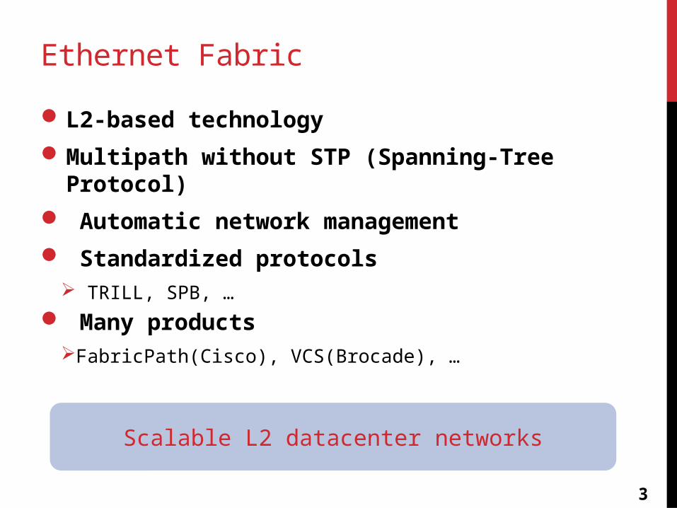
Ethernet Fabric
L2-based technology
Multipath without STP (Spanning-Tree Protocol)
Automatic network management
Standardized protocols TRILL, SPB, …
Many productsFabricPath(Cisco), VCS(Brocade), …
Scalable L2 datacenter networks
4
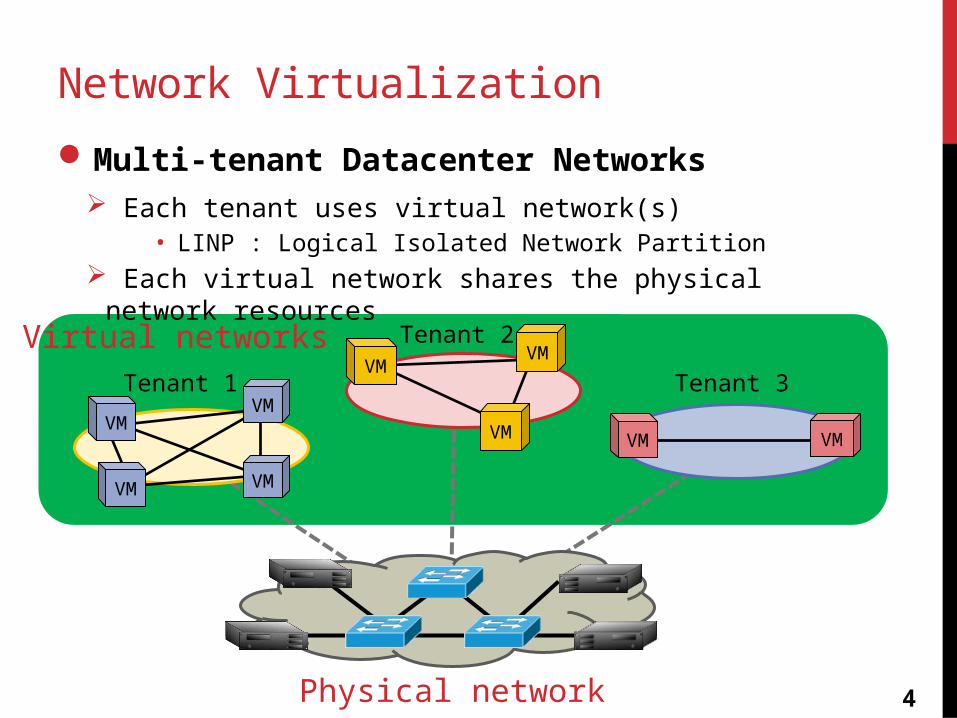
Network Virtualization
Multi-tenant Datacenter Networks Each tenant uses virtual network(s)
• LINP : Logical Isolated Network Partition Each virtual network shares the physical network resources
Physical network
VM
VM
Tenant 1
Tenant 2
Tenant 3VM
VM VM
Virtual networks
VM
VM
VM
VM
5
Traditional approach
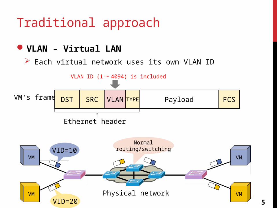
VLAN – Virtual LAN Each virtual network uses its own VLAN ID
DST VLAN Payload FCSVM's frame SRC TYPE
Ethernet header
VLAN ID (1~ 4094) is included
VM
VM
VID=10
VID=20
VM
VMPhysical network
Normalrouting/switching
6
VLAN limitations
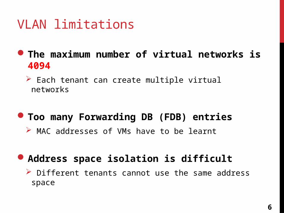
The maximum number of virtual networks is 4094 Each tenant can create multiple virtual networks
Too many Forwarding DB (FDB) entries MAC addresses of VMs have to be learnt
Address space isolation is difficult Different tenants cannot use the same address space
7
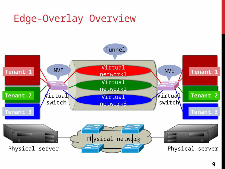
A trend – Edge-Overlay approach
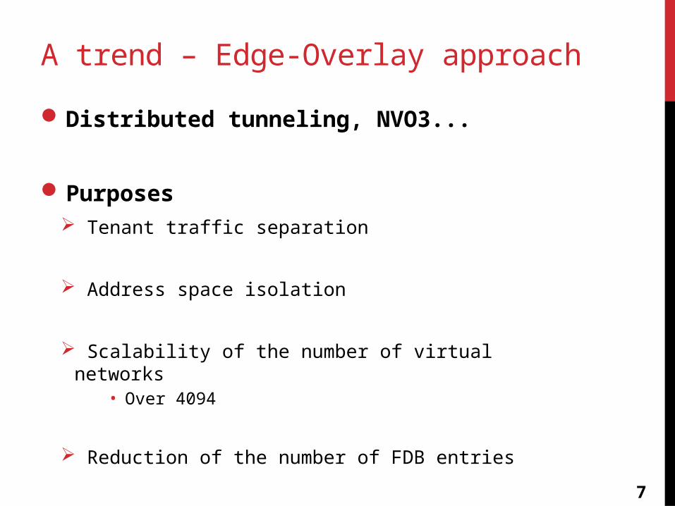
Distributed tunneling, NVO3...
Purposes Tenant traffic separation
Address space isolation
Scalability of the number of virtual networks• Over 4094
Reduction of the number of FDB entries
8
Key technologies
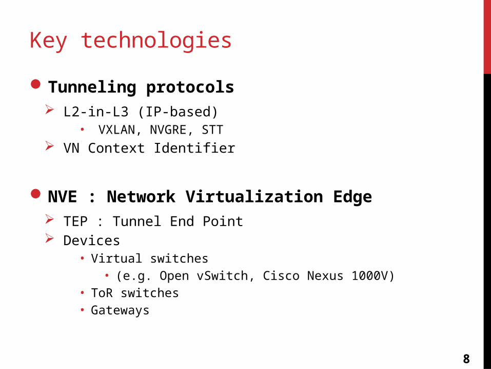
Tunneling protocols L2-in-L3 (IP-based)
• VXLAN, NVGRE, STT VN Context Identifier
NVE : Network Virtualization Edge TEP : Tunnel End Point Devices
• Virtual switches • (e.g. Open vSwitch, Cisco Nexus 1000V)
• ToR switches• Gateways
9
VM
Edge-Overlay Overview
VM
VM
VM
Physical network
Virtual network1
Virtual network2
Virtual network3
VM
VM
VM
VM
Physical server Physical server
Virtualswitch
Tenant 1
Tenant 2
Tenant 3
Tenant 1
Tenant 2
Tenant 3
Virtualswitch
NVE NVE
Tunnel
10
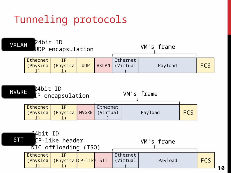
Tunneling protocols
Ethernet(Physical)
IP(Physical)
VXLANUDP FCSEthernet(Virtual)
Payload
VXLAN VM's frame
Ethernet(Physical)
IP(Physical)
NVGRE FCSEthernet(Virtual)
Payload
NVGRE VM's frame
Ethernet(Physical)
IP(Physical)
STTTCP-like FCSEthernet(Virtual)
Payload
STT VM's frame
24bit IDUDP encapsulation
24bit IDIP encapsulation
64bit IDTCP-like headerNIC offloading (TSO)
11
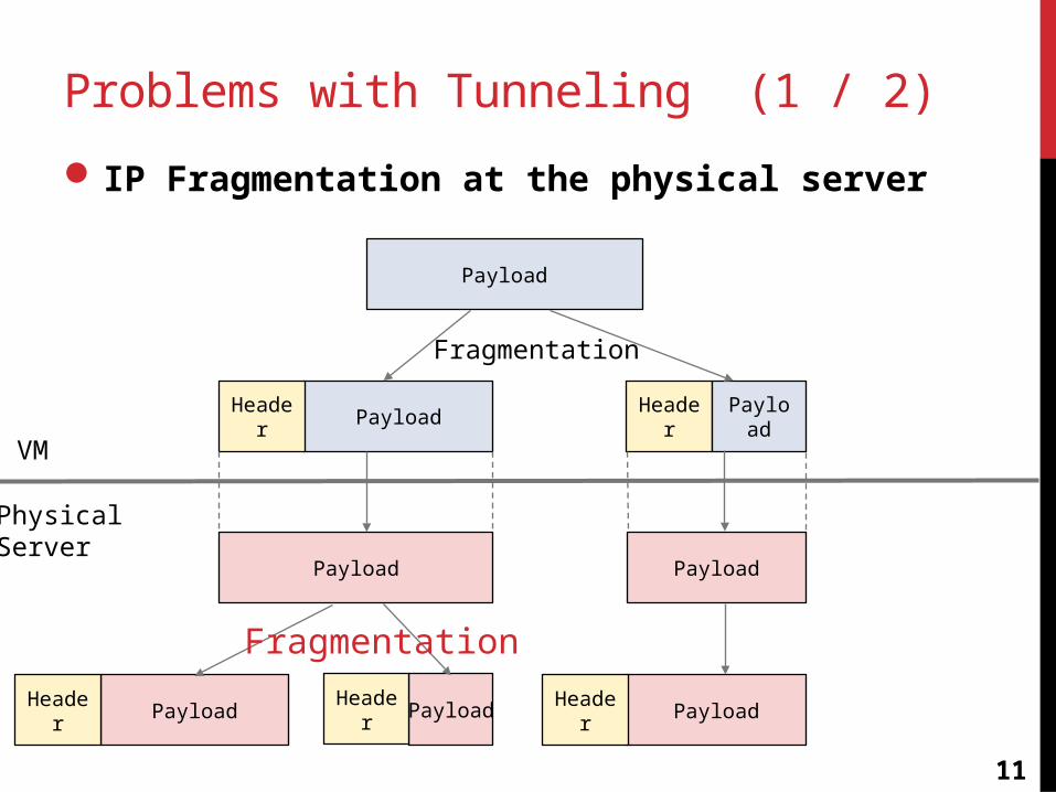
Problems with Tunneling (1 / 2)
IP Fragmentation at the physical server
Payload
PayloadHeader
Payload Payload
PayloadHeader PayloadHeader
VM
PhysicalServer
Header Payload
PayloadHeader
Fragmentation
Fragmentation
12
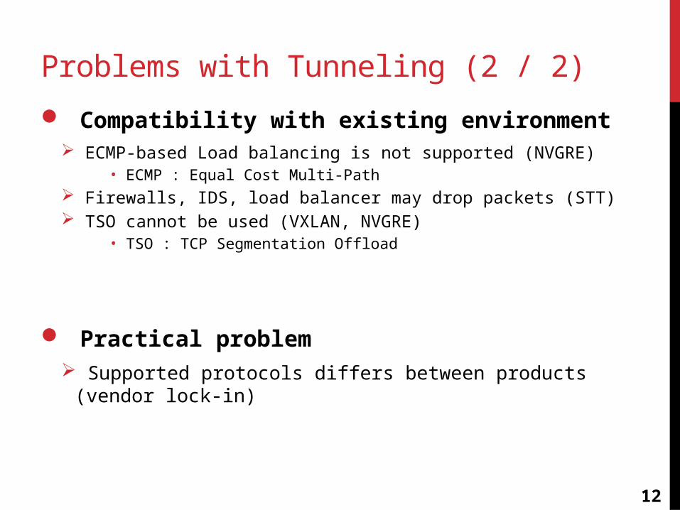
Problems with Tunneling (2 / 2)
Compatibility with existing environment ECMP-based Load balancing is not supported (NVGRE)
• ECMP : Equal Cost Multi-Path Firewalls, IDS, load balancer may drop packets (STT) TSO cannot be used (VXLAN, NVGRE)
• TSO : TCP Segmentation Offload
Practical problem Supported protocols differs between products (vendor lock-in)
13
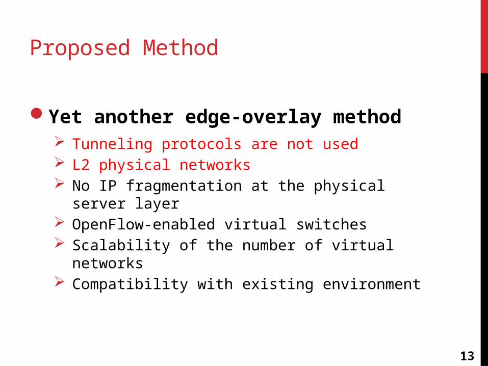
Proposed Method
Yet another edge-overlay method Tunneling protocols are not used L2 physical networks No IP fragmentation at the physical server layer OpenFlow-enabled virtual switches Scalability of the number of virtual networks Compatibility with existing environment
14
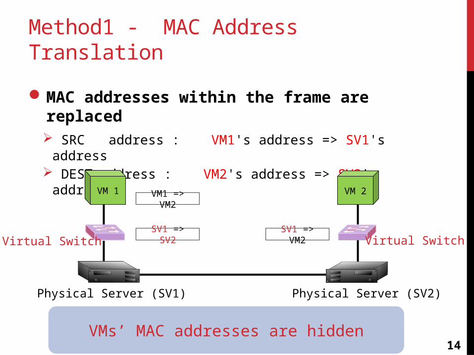
Method1 - MAC Address Translation
MAC addresses within the frame are replaced SRC address : VM1's address => SV1's address DEST address : VM2's address => SV2's address
VM 1 VM 2VM1 => VM2
Physical Server (SV1) Physical Server (SV2)
SV1 => SV2 SV1 => VM2Virtual Switch Virtual Switch
VMs’ MAC addresses are hidden
15
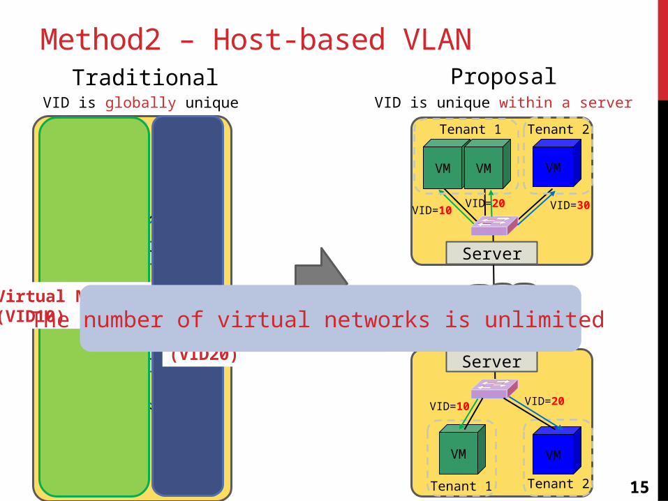
Method2 – Host-based VLAN
VM VM VM
Tenant 1 Tenant 2
VID=10VID=10 VID=20
Server
Server
VM VM
Tenant 1 Tenant 2
VID=20VID=10
Virtual Network(VID10)
Virtual Network(VID20)
Traditional
VM VM VM
Tenant 1 Tenant 2
VID=10VID=20 VID=30
Server
Server
VM VM
Tenant 1 Tenant 2
VID=20VID=10
ProposalVID is globally unique VID is unique within a server
The number of virtual networks is unlimited
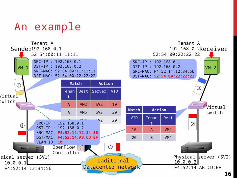
An example
VM 1
Virtual switch
Sender
SRC-IP : 192.168.0.1DST-IP : 192.168.0.2SRC-MAC: 52:54:00:11:11:11DST-MAC: 52:54:00:22:22:22
Physical server (SV1)
Tenant A192.168.0.152:54:00:11:11:11
10.0.0.1F4:52:14:12:34:56
TraditionalDatacenter network
VM 2
①
②
②
②
③
SRC-IP : 192.168.0.1DST-IP : 192.168.0.2SRC-MAC: F4:52:14:12:34:56DST-MAC: 52:54:00:22:22:22
ReceiverTenant A
192.168.0.252:54:00:22:22:22
Match Action
VID Tenant Dest
10 A VM2
20 B VM4
Physical server (SV2)10.0.0.2F4:52:14:AB:CD:EF
OpenFlowController
Virtual switch
16
Match Action
Tenant Dest Server VID
A VM2 SV2 10
A VM5 SV3 30
B VM4 SV2 20
SRC-IP : 192.168.0.1DST-IP : 192.168.0.2SRC-MAC: F4:52:14:12:34:56DST-MAC: F4:52:14:AB:CD:EFVLAN ID: 10
17
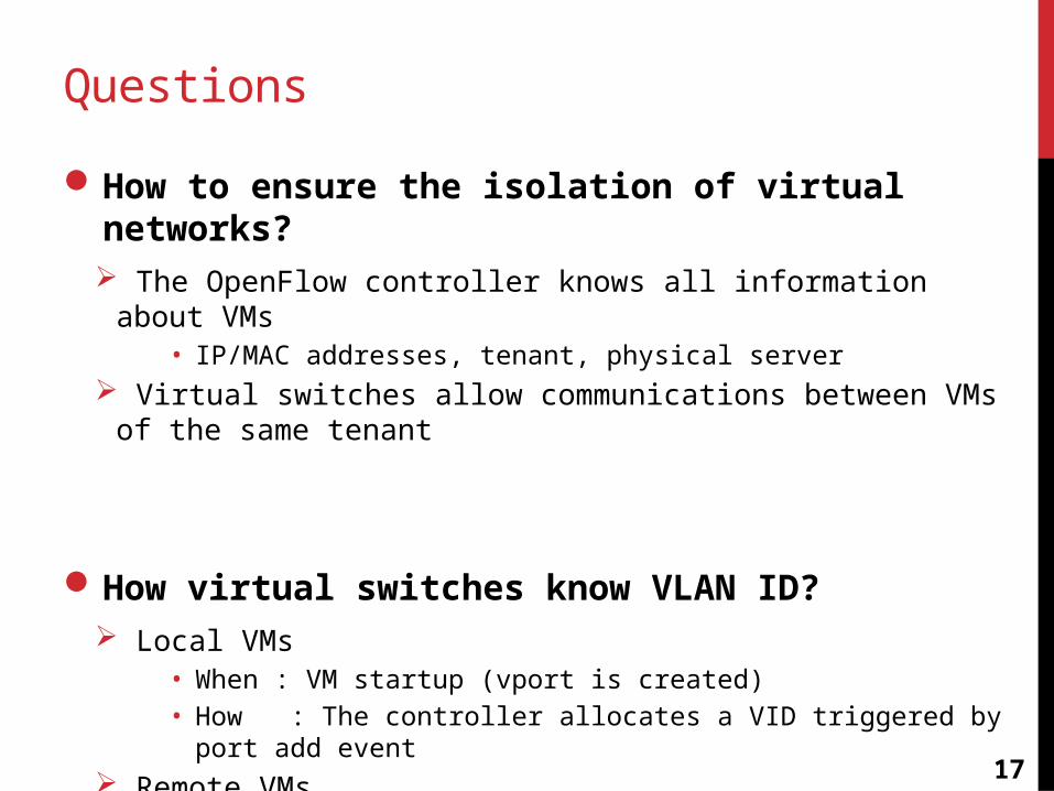
Questions
How to ensure the isolation of virtual networks? The OpenFlow controller knows all information about VMs
• IP/MAC addresses, tenant, physical server Virtual switches allow communications between VMs of the same
tenant
How virtual switches know VLAN ID? Local VMs
• When : VM startup (vport is created)• How : The controller allocates a VID triggered by port add event
Remote VMs• When : First ARP request• How : The controller writes a proper flow entry
18
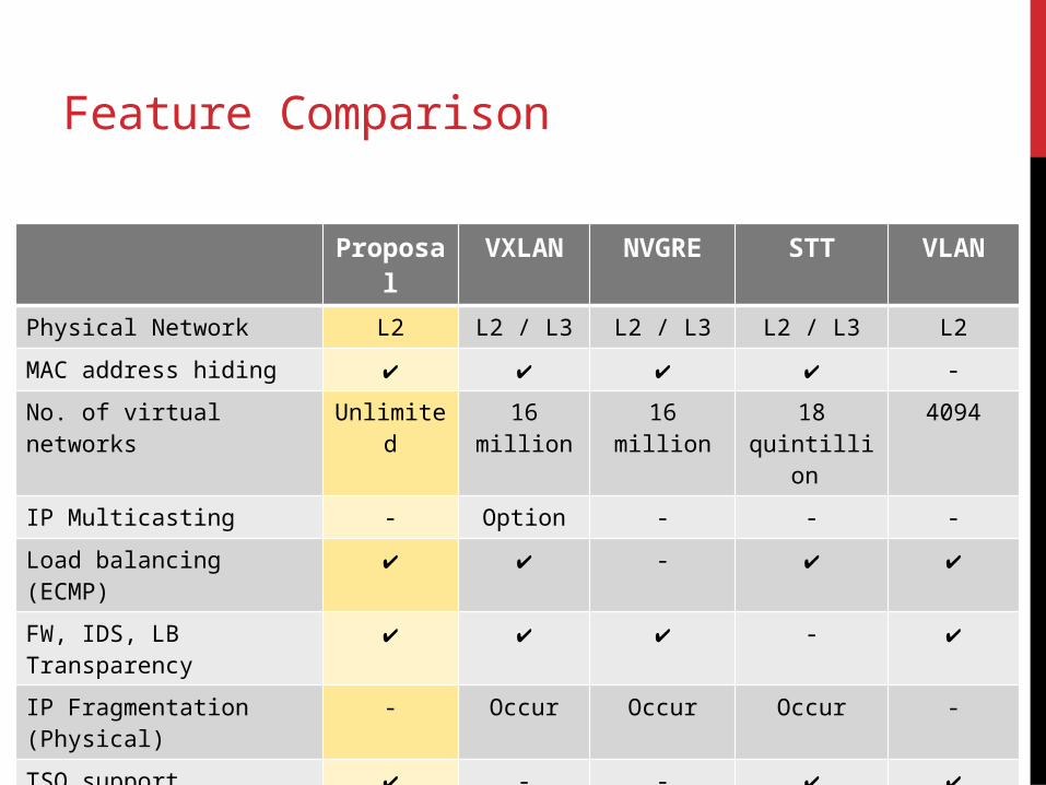
Feature Comparison
Proposal VXLAN NVGRE STT VLAN
Physical Network L2 L2 / L3 L2 / L3 L2 / L3 L2
MAC address hiding ✔ ✔ ✔ ✔ -
No. of virtual networks Unlimited 16 million 16 million 18 quintillion 4094
IP Multicasting - Option - - -
Load balancing (ECMP) ✔ ✔ - ✔ ✔
FW, IDS, LB Transparency ✔ ✔ ✔ - ✔
IP Fragmentation (Physical) - Occur Occur Occur -
TSO support ✔ - - ✔ ✔
19
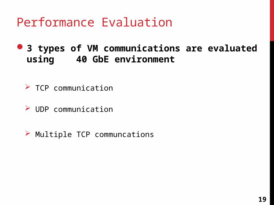
Performance Evaluation
3 types of VM communications are evaluated using 40 GbE environment
TCP communication
UDP communication
Multiple TCP communcations
20
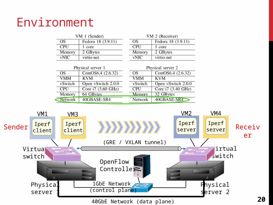
Environment
Virtualswitch
Physical server 1
VM1
Iperfclient
VM2
Physical server 2
40GbE Network (data plane)
Virtualswitch
OpenFlowController
Iperfserver
(GRE / VXLAN tunnel)
1GbE Network (control plane)
Iperfclient
VM3 VM4
IperfserverSender Receiver
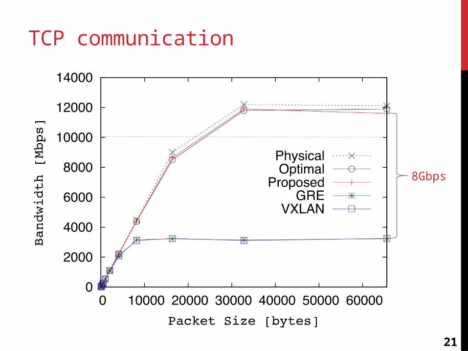
TCP communication
21
8Gbps
22
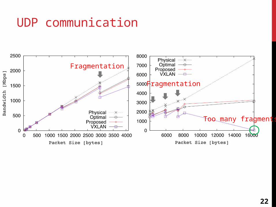
UDP communication
Fragmentation
Fragmentation
Too many fragments
23
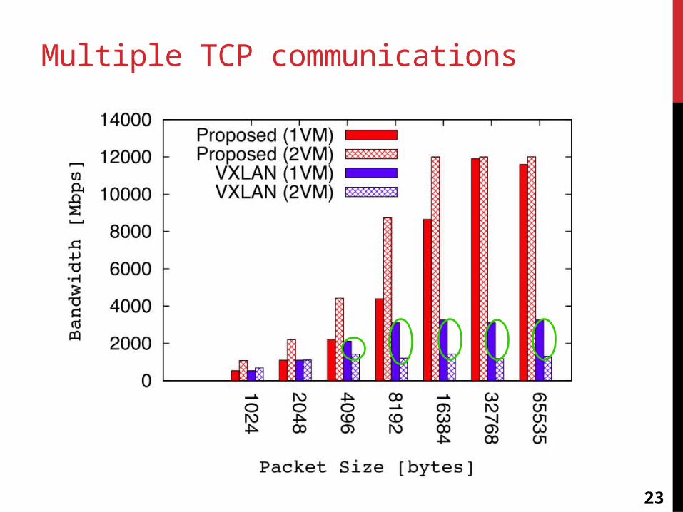
Multiple TCP communications
24
Conclusion
Yet another Edge-overlay method No tunneling protocols No IP fragmentation at physical server layer Higher throughput than tunneling protocols
• Over 10 Gbps L2 network
Future Work Inter DC communication support MPLS support