Embed Size (px)
Citation preview
Item Specification 0i-TF
Controlled axis
Max. feed axes 4 AXIS
Feed axes X/Z/(Cs)
Max. simultaneosly controlled axis 4
Least command increment 0.001mm / 0.0001" ◯
Operation functions
Pulse handle feed X1, X10, X100 ◯
Feedrate per minute G98 ◯
Feedrate per revolution G99 ◯
Interpolation functions
Linear interpolation G01 ◯
Circular interpolation G02, G03 ◯
Dwell G04 ◯
Polar cordinate interpolation G12.1, G13.1 ◯
Cylindrical interpolation G70.1 ◯
Variable lead thread cutting G34 ◯
Continuous threading ◯
Reference position return G28 ◯
Reference position return check G27 ◯
Feed functionRapid traverse rate override F0, 25%, 50%, 100% ◯
Feedrate override 0~150%
Spindle functionSpindle orientation ◯
Rigid tapping ◯
Tool functions
Tool number command T4-Digt / T2-Digt ◯
Tool nose radius compensation G40 ~ G42 ◯
Tool offset pairs ◯
Tool geometry/wear offset GEOMETRY & WEAR DATA ◯
Tool life management ◯
Tool path graphic display ◯
Automatic tool offset G36, G37 ◯
Direct input of tool offset value measured B ◯
Program input
Absolute/incremental programming ◯
Multiple repetitive cycle G70 ~ G76 ◯
Canned cycles G90, G92, G94 ◯
Inch/metric conversion G20 / G21 ◯
Program restart ◯
Retraction for rigid tapping ◯
Max. programmable dimension ±99999.999mm/±9999.9999" ◯
M function M3 digit ◯
Custom macro ◯
Canned cycle for drilling ◯
Direct drawing dimension programming ◯
Programmable data input G10 ◯
Optional block skip ◯
Workpiece coordinate system G52 ~ G59 ◯
Number of registerable programs 400EA
Setting and
display
Alarm & Operator history display ALARM & OPERATION DISPLAY ◯
Run hour and parts count display RUNNING TIME & PART NO. DISPLAY ◯
Display spindle & servo overload SPINDLE & SERVO LOAD DISPLAY ◯
Self-diagnosis function ◯
Extended part program editing COPY,MOVE, CHANGE OF NC PROGRAM ◯
Display screen 10.4" color
Data input/outputMemory card input/output ◯
USB memory input/output ◯
Editing operation Part program storage size 512Kbyte(1280m) ◯
Manual guide i Manual Guide i ◯
▒ NC Unit Specifications / FANUC Series
CNC TURNING CENTER
SL 3500 series
❖ Design and specifications subject to change without notice.
140 East Ridgewood Ave. Suite 415, Paramus NJ 07652Office: 833-777-7632, Sales: (586) 246-1432Email: [email protected] www.esmecamerica.com
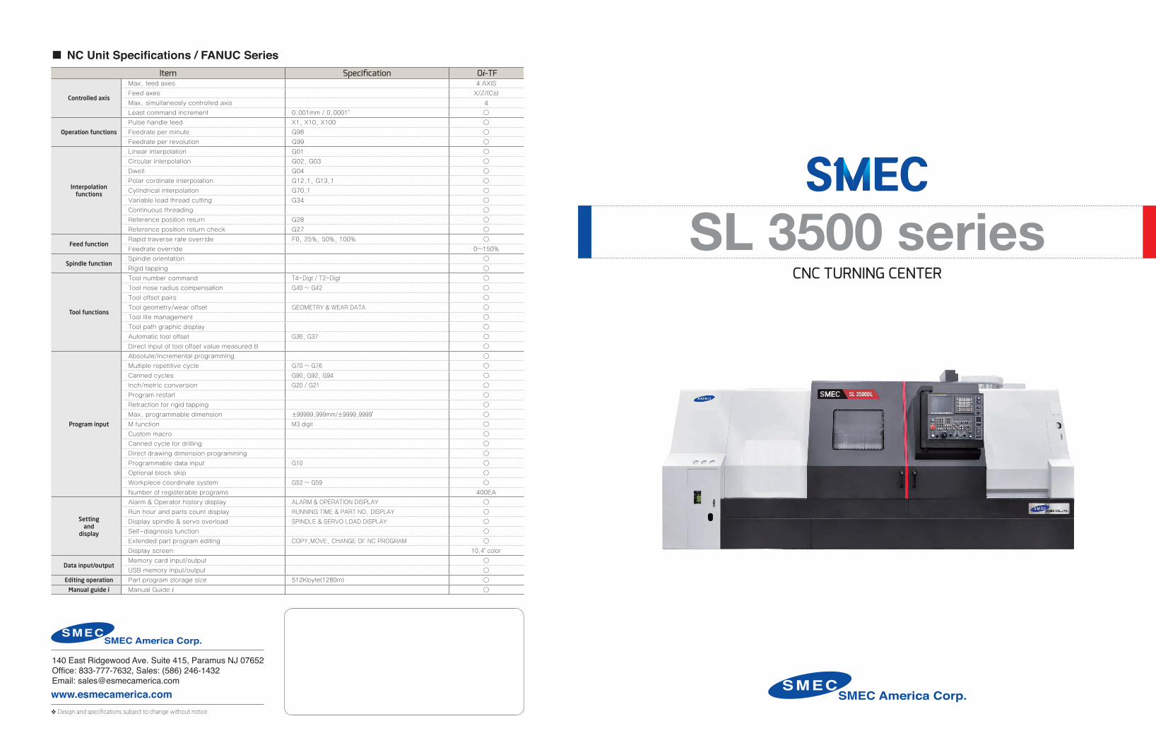
· Cast iron structure for superior dampening characteristics and thermal displacement
· Rigid 45 degree slant bed design for heavy-duty machining
· Torque tube design to minimize bending and twisting
· Integrated box ways for long-term rigidity and heavy-duty machining
SMEC'S Advanced Engineering and Machine Design
SMEC America Crop. 32
SL 3500BLSL 3500BLM
SMEC
SamsungMachine Tools
EngineeringCompany
•1988 - Started as Samsung Heavy Industries Machine Tools Business
•1989 - Horizontal and vertical machining center technology partnership with OKK Japan
•1991 - Turning center and vertical machining center technology partnership with Mori Seiki
•1996 - 5-sided processing center technology partnership with Toshiba
•1999 - Spun out from Samsung Aerospace Industries and established SMEC Co., Ltd
•2018 - SMEC America Corp established to provide factory support to the distributor network and customers
Company History
SMEC America Crop. 54
CNC Turning Center SL 3500BL/3500BLM
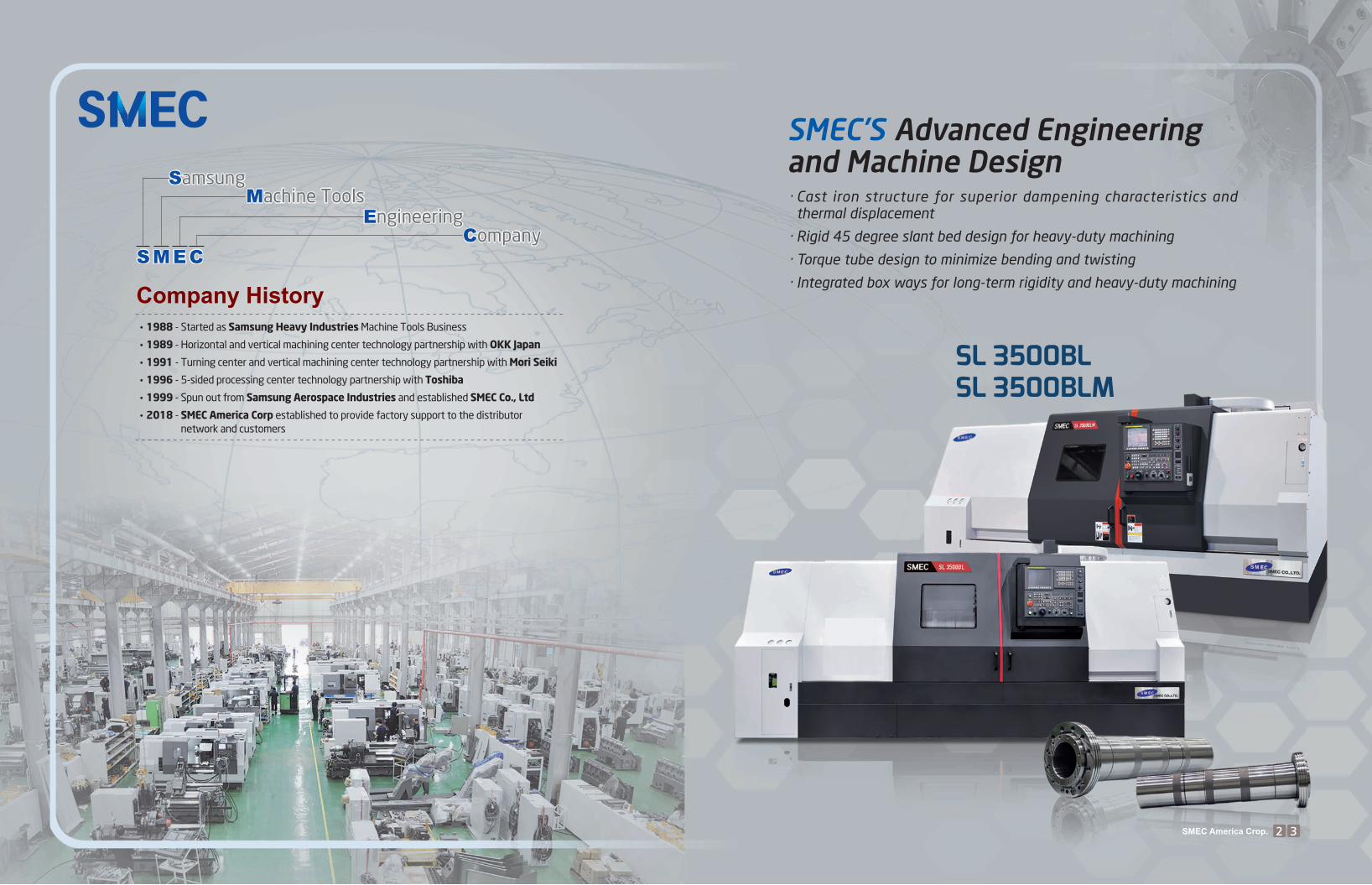
SL 3500BL/3500BLM is a heavy duty, ultra precision Turning Center, combined with SMEC's advanced technological features.
Highly Reliable and Rigid Structural Design · One piece Meehanite casting with heavily ribbed torque tube design ·Rigid bed supports for powerful cutting ·Excellent vibration dampening and thermal displacement design
Max. Turning Length
Max. Turning Diameter
High Accuracy, High Rigidity Spindle
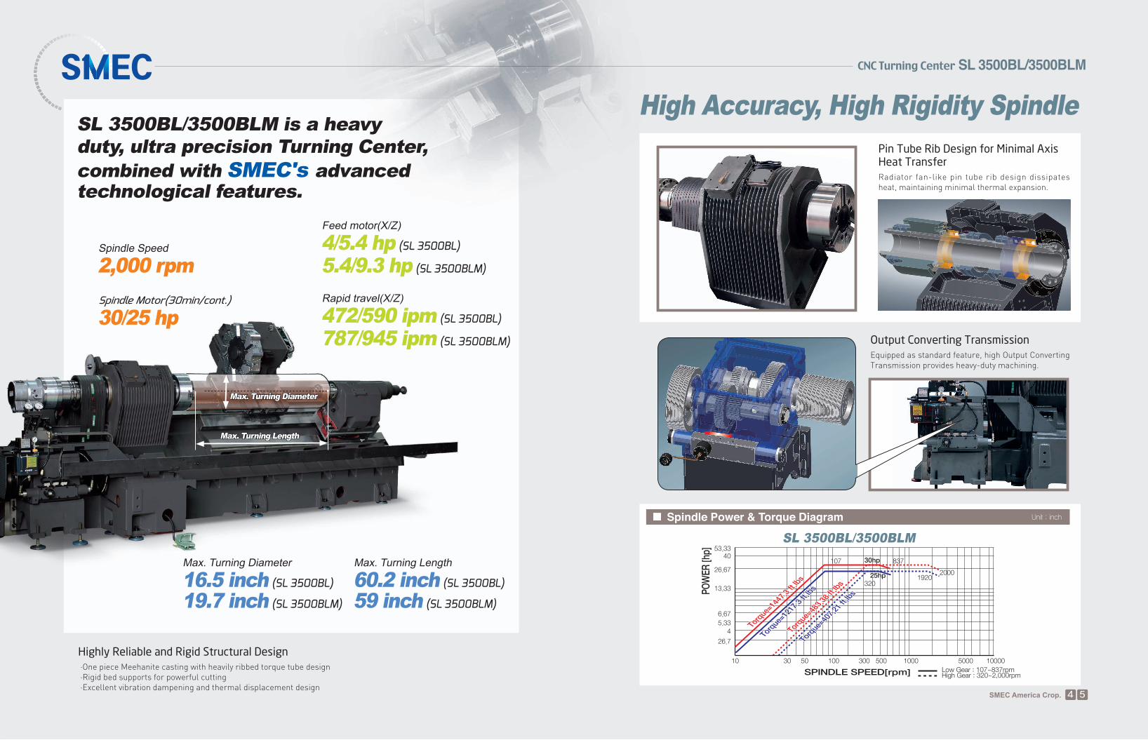
▒ Spindle Power & Torque Diagram Unit : inch
Output Converting TransmissionEquipped as standard feature, high Output Converting Transmission provides heavy-duty machining.
Pin Tube Rib Design for Minimal Axis Heat Transfer Radiator fan-like pin tube rib design dissipates heat, maintaining minimal thermal expansion.
26.7
45.33
6.67
26.67
53.3340
3010
107 837
20001920
320
50 100 300 500 1000 5000 10000
13.33
SPINDLE SPEED[rpm]
POW
ER [h
p]
Low Gear : 107~837rpmHigh Gear : 320~2,000rpm
Torq
ue=14
47.3
ft.lb
s
Torq
ue=12
17.3
ft.lb
s
Torq
ue=48
3.38
ft.lb
s
Torq
ue=40
7.21
ft.lb
s
Torq
ue=14
47.3
ft.lb
s
Torq
ue=12
17.3
ft.lb
s
Torq
ue=48
3.38
ft.lb
s
Torq
ue=40
7.21
ft.lb
s
30hp
25hp
30hp
25hp
SL 3500BL/3500BLM
Spindle Speed
2,000 rpm
Spindle Motor(30min/cont.)
30/25 hp
Max. Turning Length
60.2 inch (SL 3500BL)
59 inch (SL 3500BLM)
Max. Turning Diameter
16.5 inch (SL 3500BL)
19.7 inch (SL 3500BLM)
Rapid travel(X/Z)
472/590 ipm (SL 3500BL)
787/945 ipm (SL 3500BLM)
Feed motor(X/Z)
4/5.4 hp (SL 3500BL)
5.4/9.3 hp (SL 3500BLM)
SL 3500BL / 3500BLMCNC TURNING CENTER
�
SMEC America Crop. 76
Variety of Functions
▒ Machine Structure
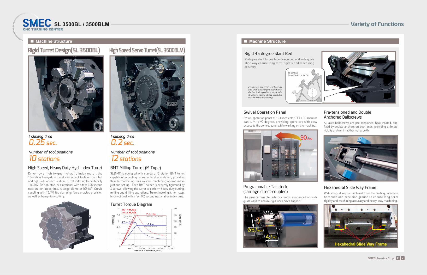
Hexahedral Slide Way Frame
Wide integral way is machined from the casting, induction hardened and precision ground to ensure long-term rigidity and machining accuracy and heavy-duty machining.
Pre-tensioned and Double Anchored Ballscrews
Swivel Operation PanelSwivel operation panel of 10.4 inch color TFT LCD monitor can turn to 90 degree, providing operators with easy access to the control panel while working on the machine.
Rigid 45 degree Slant Bed
45 degree slant torque tube design bed and wide guide slide way ensure long term rigidity and machining accuracy.
Featuring superior workability and chip-discharging capability, the bed is designed in a single tube structure boasting strong durability even in heavy-duty cutting.
90deg
SL 35/35MCCross-Section of the Bed
All axes ballscrews are pre-tensioned, heat treated, and fixed by double anchors on both ends, providing ultimate rigidity and minimal thermal growth.
4.7inch
MT4
Ø5.1inch
Programmable Tailstock(carriage direct-coupled) The programmable tailstock body is mounted on wide guide ways to ensure rigid work piece support.
▒ Machine Structure
Indexing time
0.25 sec. Number of tool positions
10 stations
Rigid Turret Design(SL 3500BL)
Indexing time
0.2 sec.Number of tool positions
12 stationsBMT Milling Turret (M Type)SL35MC is equipped with standard 12-station BMT turret capable of accepting rotary tools at any station, providing flexible machining thru various machining operations in just one set-up. Each BMT holder is securely tightened by 4 screws, allowing the turret to perform heavy-duty cutting, milling and drilling operations. Turret indexing is non-stop, bi-directional with a fast 0.2 second next station index time.
High Speed Servo Turret(SL 3500BLM)
High Speed, Heavy Duty Hyd. Index TurretDriven by a high torque hydraulic index motor, the 10-station heavy-duty turret can accept tools on both left and right side of each station. Turret indexing (repeatability ± 0.0002" )is non-stop, bi-directional with a fast 0.25 second next station index time. A large diameter (Ø9.84") Curvic coupling with 10.494 lbs clamping force enables precision as well as heavy-duty cutting.
Turret Torque Diagram
SPINDLE SPEED[min-1]
POW
ER [h
p]
TORQ
UE [lb
s.ft]7.4 Hp
5 Hp17.4 ft.lbs
25.8 ft.lbs
27.7 ft.lbs
Hexahedral Slide Way Frame
SL 3500BL / 3500BLMCNC TURNING CENTER
SAMSUNG MACHINE TOOLS 98
Variety of Functions
SMEC America Crop. 98
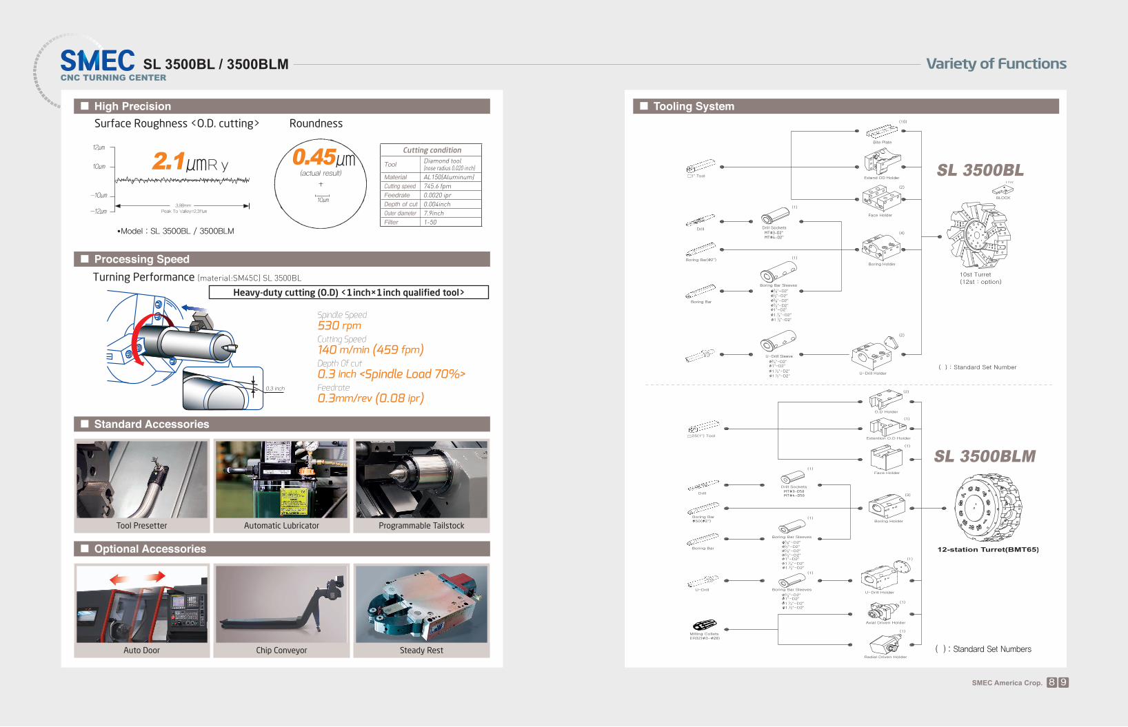
▒ High Precision
▒ Standard Accessories
Programmable TailstockAutomatic LubricatorTool Presetter
Surface Roughness <O.D. cutting>
▒ Processing Speed
Spindle Speed530 rpmCutting Speed140 m/min (459 fpm)Depth 0f cut0.3 inch <Spindle Load 70%>Feedrate0.3mm/rev (0.08 ipr)
Heavy-duty cutting (O.D) <1 inch×1 inch qualified tool>
Turning Performance (material:SM45C) SL 3500BL
Roundness
10㎛
0.45㎛(actual result)
▒ Optional Accessories
Steady RestChip ConveyorAuto Door
0.3 inch
▒ Tooling System
SL 3500BL
SL 3500BLM
( ) : Standard Set Numbers
●Model : SL 3500BL / 3500BLM
2.1㎛ R y12㎛
10㎛
-10㎛
-12㎛3.98mm
Peak To Valley=2.311㎛
Cutting condition
ToolDiamond tool (nose radius 0.020 inch)
Material AL150(Aluminum)Cutting speed 745.6 fpmFeedrate 0.0020 iprDepth of cut 0.004inchOuter diameter 7.9inchFilter 1-50
SL 3500BL / 3500BLMCNC TURNING CENTER
Variety of Functions
SMEC America Crop. 1110
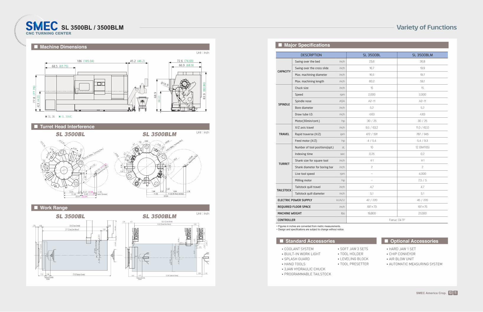
▒ Major Specifications
▒ Standard Accessories •COOLANT SYSTEM •BUILT-IN WORK LIGHT •SPLASH GUARD •HAND TOOLS •3JAW HYDRAULIC CHUCK •PROGRAMMABLE TAILSTOCK
•SOFT JAW 3 SETS •TOOL HOLDER •LEVELING BLOCK •TOOL PRESETTER
▒ Optional Accessories •HARD JAW 1 SET •CHIP CONVEYOR •AIR BLOW UNIT •AUTOMATIC MEASURING SYSTEM
DESCRIPTION SL 3500BL SL 3500BLM
CAPACITY
Swing over the bed inch 23.6 26.8
Swing over the cross slide inch 16.7 19.9
Max. machining diameter inch 16.5 19.7
Max. machining length inch 60.2 59.1
SPINDLE
Chuck size inch 15 15
Speed rpm 2,000 2,000
Spindle nose ASA A2-11 A2-11
Bore diameter inch 5.2 5.2
Draw tube I.D. inch 4.63 4.63
Motor(30min/cont.) hp 30 / 25 30 / 25
TRAVEL
X/Z axis travel inch 9.5 / 63.2 11.0 / 62.0
Rapid traverse (X/Z) ipm 472 / 591 787 / 945
Feed motor (X/Z) hp 4 / 5.4 5.4 / 9.3
TURRET
Number of tool positions(opt.) st. 10 12 (BMT65)
Indexing time sec 0.25 0.2
Shank size for square tool inch □1 □1
Shank diameter for boring bar inch 2 2
Live tool speed rpm - 4,000
Milling motor hp - 7.5 / 5
TAILSTOCKTailstock quill travel inch 4.7 4.7
Tailstock quill diameter inch 5.1 5.1
ELECTRIC POWER SUPPLY kVA/V 42 / 220 45 / 220
REQUIRED FLOOR SPACE inch 197×73 197×75
MACHINE WEIGHT lbs 19,800 21,000
CONTROLLER Fanuc Oi-TF
▒ Machine Dimensions
186 (185.04)
68.5 (65.75)
45.2 (46.2) 72.6 (74.69)
66.9 (68.9)
Ø16.9
14.8
77.8 (77.76)
42.9 (44.22) 68.9
83.9 (83.86)
42.9 (44.22)
∅16.54 (∅19.69)
[Max. Machining Dia.]
8.27 (9.84) 1.181.579.4511.02 9.45 (11.02)[X-axis Stroke]
20.47 (22.04)
∅11.97
1.57
4.64
∅2
12.36
1.97
0.28
4.64
∅12.16
(1.97)1.57
4.64
∅12.91
∅26.42 [Max. Turning Dia.]
∅19.69
[Max
. Mac
hining
Dia.
]
22.0411.02
7.88 9.84 1.181.57
1.57
11.02 [X-Axis stroke]
∅25.2
[Max
. Turn
ing Dia.
]
∅9.4
∅9.64∅2
∅10.6
3.82
3.78
3.25
3.78
1
0.29
1.57
3.78
3.7
2.64
2.08
3.7
3.15
3.15
3.15
12", 15"Chuck
4.062.76 33.6 [Z-axis Stroke]
5.9127.7 [Z-axis Zero Return]
0.28
8[X-axis Zero Return]0.27
1.18
9.45
[X-axia Stroke]
1.57
9.45
7.13 3.94Tailstock Spindle Stroke
27.8 [Tailstock Stroke]
15"C
huck
62.01 [Z-axis Stroke]
55.52 [Z-axis Zero Return] 6.45
0.79
5.28 1.81
7.8
71.5
7 1.5
7
1.5
78.2
7
4.728.31
2.76 5.51
Tailstock Spindle Stroke
57.68 [Tailstock Stroke]
9.5
1.1
80.3
4[X
-axi
s Zer
o R
eturn
]
11.0
2[X
-axia
Str
oke]
19.6
8[M
ax. m
achin
ing D
ia.]
▒ Turret Head InterferenceUnit : inch
▒ Work RangeUnit : inch
Unit : inch
•Figures in inches are converted from metric measurements.•Design and specifications are subject to change without notice.
▣ SL 35 ▣ SL 35MC
SL 3500BL SL 3500BLM
SL 3500BL SL 3500BLM


![GB Version 1 - Sangean...Select alarm system 1 or 2 by pressing the alarm button [14] or [15]. Display will blink with selected alarm Press alarm set button [16] Display will blink](https://img.pdfslide.us/doc/110x75/5fe727636b861223ed4c8d14/gb-version-1-sangean-select-alarm-system-1-or-2-by-pressing-the-alarm-button.jpg)