Embed Size (px)
Citation preview

NBN Co Network Design Rules provided to the ACCC in support of NBN Co’s Special Access Undertaking in respect of the NBN Access Service
19 December 2011

NBN Co Network Design Rules
i
NBN Co Limited (ACN 136 533 741) and NBN Tasmania Limited (ACN 138 338 271)
Network Design Rules
19 December 2011
Copyright
This document is subject to copyright and must not be used except as permitted below or under the Copyright Act 1968 (Cth). You must
not reproduce or publish this document in whole or in part for commercial gain without the prior written consent of NBN Co. You may
reproduce and publish this document in whole or in part for educational or non-commercial purposes as approved by NBN Co in writing.
Copyright © 2011 NBN Co Limited. All rights reserved.
Environment
NBN Co asks that you consider the environment before printing this document.

NBN Co Network Design Rules
ii
Table of Contents 1 INTRODUCTION 1
2 PURPOSE 1
3 NETWORK DESIGN 2
3.1 High Level Design Overview 2 3.2 GPON Access Domain 4
3.2.1. GPON NTD (ONT) 4 3.2.2. PON 5 3.2.2.1. Fibre 6 3.2.2.2. Distribution Fibre Network 8 3.2.2.3. Fibre Distribution Hub 11 3.2.2.4. Local Fibre Network 12 3.2.2.5. PON Planning Hierarchy 14 3.2.2.6. Optical Budget 17 3.2.3. OLT 18
3.3 Point to point Fibre Access Domain 19 3.3.1. Fibre 19 3.3.2. Distribution Fibre Network 19 3.3.3. Fibre Distribution Hub 19 3.3.4. Local Fibre Network 19
3.4 TD-LTE Wireless Access Domain 20 3.4.1. Wireless NTD (WNTD) 21 3.4.2. Radio Spectrum 21 3.4.3. eNodeB (Base Station) 21 3.4.4. Aggregation and Transport for Wireless 22 3.4.4.1. Microwave Transport Equipment 22 3.4.4.2. Fibre Transport Equipment 23 3.4.4.3. FAN Aggregation Switch 23 3.4.4.4. Transport 23 3.4.4.5. POI Aggregation Switch 24 3.4.5. Packet Data Network Gateway (PDN-GW) 24 3.4.6. Wireless Access Planning Hierarchy 24
3.5 Satellite Access 26 3.5.1. Satellite NTD (Very Small Aperture Terminal (VSAT)) 26 3.5.2. Satellite 27 3.5.2.1. Systems Engineering Design 27 3.5.2.2. RF Spectrum and Orbital Slots 29 3.5.3. RF Sub-System 30 3.5.4. VSAT Baseband Sub-System 30 3.5.5. Service Control 30
3.6 Transport Domain 31 3.6.1. Dense Wavelength Division Multiplexing (DWDM) 31 3.6.1.1. Reconfigurable Optical Add-Drop Multiplexers (ROADMs) 32 3.6.1.2. Optical Line Repeaters (OLRs) 32 3.6.1.3. DWDM Network Topologies 32 3.6.2. Managed Services Transmission 36 3.6.3. Direct Fibre 37
3.7 Aggregation Domain 39 3.7.1. Ethernet Aggregation Switch (EAS) 39 3.7.2. Ethernet Fanout Switch (EFS) 40 3.7.3. Ethernet Combined Switch (ECS) 42 3.7.4. Aggregation Domain and POI Architecture 42
4 APPENDIX - DEFINITIONS 45

NBN Co Network Design Rules
Commercial-in-Confidence
iii
Table of Tables Table 1 Summary of fibre & connector types used in the network ....................................................................... 7 Table 2 Fibre Standards Reference Code ............................................................................................................... 8 Table 3 MDU Classifications ................................................................................................................................ 13 Table 4 MDU Fibre Allocation: ............................................................................................................................ 13 Table 5 12 FDH FSAM Fibre Requirements per FDH ........................................................................................... 16 Table 6 Maximum Optical Loss ........................................................................................................................... 18 Table 7 Preliminary RF Spectrum Plan ................................................................................................................ 29 Table 8 Acronyms, Terms and Definitions .......................................................................................................... 46
Table of Figures
Figure 1 Target High Level Architecture Context Diagram ................................................................................... 3 Figure 2 Focus of this Document .......................................................................................................................... 3 Figure 3 Ribbon Fibre ............................................................................................................................................ 6 Figure 4 Connector and Multi-port Connections .................................................................................................. 6 Figure 5 Traffic paths available when failure occurs ............................................................................................ 9 Figure 6 Traffic paths available when failure occurs on return spur .................................................................. 10 Figure 7 FDH PON Connection ............................................................................................................................ 11 Figure 8 Fibre Distribution Area .......................................................................................................................... 14 Figure 9 Fibre Serving Area Module Example ..................................................................................................... 15 Figure 10 16 X FSAM Distribution Cable Connectivity ........................................................................................ 15 Figure 11 12 X FSAM Distribution Cable Connectivity ........................................................................................ 16 Figure 12 Fibre Serving Area (FSA) ...................................................................................................................... 17 Figure 13 Point to Point Connection using DFN .................................................................................................. 19 Figure 14 High level interconnection block diagram of Wireless Access ............................................................ 20 Figure 15 Microwave Transport Design .............................................................................................................. 23 Figure 16 Base Station Sub-Cluster ..................................................................................................................... 25 Figure 17 Wireless Serving Area Module ............................................................................................................ 25 Figure 18 High level interconnection block diagram of Satellite Access............................................................. 26 Figure 19 Preliminary Design of User Spot Beams .............................................................................................. 28 Figure 20 Shortlisted RF Gateway Regions ......................................................................................................... 29 Figure 21 Basic DWDM physical connectivity scenarios ..................................................................................... 31 Figure 22 Standalone physical rings .................................................................................................................... 33 Figure 23 Examples of redundancy in the DWDM network................................................................................ 33 Figure 24 Overlapping physical rings .................................................................................................................. 34 Figure 25 Point-to-point spur links ..................................................................................................................... 35 Figure 26 Point-to-point standalone links........................................................................................................... 35 Figure 27 Fibre access transit ............................................................................................................................. 36 Figure 28 Unprotected Greenfields fibre access transit ..................................................................................... 36 Figure 29 Wireless access transit ........................................................................................................................ 37 Figure 30 Aggregation Domain interfaces on the EAS ........................................................................................ 39 Figure 31 Aggregation Domain interfaces on the EFS ........................................................................................ 40 Figure 32 E-NNI Mode A connection model from an Access Seeker Provider Edge (AS PE) ............................... 40 Figure 33 E-NNI Mode B connection model from a single AS PE ........................................................................ 41 Figure 34 E-NNI Mode B connection model from two AS PEs ............................................................................ 41 Figure 35 Aggregation Domain interfaces on the ECS ........................................................................................ 42 Figure 36 Two tier aggregation architecture ...................................................................................................... 43 Figure 37 One tier aggregation architecture ...................................................................................................... 44

NBN Co Network Design Rules
1
1 Introduction
This document provides an overview of the current physical network architecture and high level
design of NBN Co’s network and network components. It describes the high level solution that has
been developed by NBN Co to achieve its objectives of delivering fibre to the premises to 93%
homes and businesses, and satellite and wireless services to the remaining 7%.
This document is provided with NBN Co’s Special Access Undertaking in respect of the NBN Access
Service (‘the SAU’), and is the document referred to in the SAU as the Network Design Rules.
This version of the Network Design Rules addresses the fibre GPON, TD-LTE Wireless, Transport and
Aggregation network domains. An indicative view of the Satellite Access network design is also
provided. It is intended that the final satellite network designs, along with other aspects of the NBN
Co network will be provided to the ACCC as soon as they are available.
2 Purpose
This document is intended to be read together with NBN Co’s Special Access Undertaking (SAU).
These Network Design Rules will be provided to the ACCC as part of its assessment of the
reasonableness of NBN Co’s SAU. NBN Co’s objective is to provide certainty with respect to the
capital expenditure it may recover in relation to the design of the NBN, but also to provide an
appropriate degree of flexibility.
If the SAU is accepted, these Network Design Rules will provide a baseline design for the NBN Co
fibre, satellite and wireless networks in respect of which NBN Co may incur capital expenditure and
recover it over time through the Long Term Revenue Constraint Methodology, provided that NBN Co
also meets the Prudent Cost Condition, as specified in the SAU, in respect of that capital
expenditure.
The process for varying or enhancing NBN Co’s network design which is beyond the scope of these
Network Design Rules is separately set out in the SAU (Schedule 8). On completion of the process
for variation or enhancement of the network design, NBN Co will be required to update these
Network Design Rules accordingly. These Network Design Rules will also be reviewed in accordance
with the conditions specified in the SAU.

NBN Co Network Design Rules
2
3 Network Design
3.1 High Level Design Overview
The NBN Co network has been divided into domains to allow for communication of the overall
solution.
The target high level architecture is shown in Figure 1. This view includes the IT platforms, which are
out of scope for this High Level Design, but must be interfaced to, to achieve a complete working
solution. The target high level architecture will not be achieved for a number of years, and will be
implemented in steps determined by the services introduced.
A first step towards the target architecture is captured in
Figure 2. These are domains introduced to support the NBN Co Fibre Access Service Ethernet
Bitstream (Data) service, the NBN Co Wireless Access Service Ethernet Bitstream (Data) service, the
NBN Co Fibre Access Service Multicast service and the NBN Co Fibre Access Service Analogue
Telephony (Voice) service. The Satellite Access Service will be delivered in the future, and the
supporting Satellite Access domain network design is still under development.
The high level domains and their functions are as follows:
Network: Key function is the carriage of customer traffic
o Access: Various technology solutions to allow end users to be connected to the NBN
Co network. The expected long term technology domains are Fibre (GPON),
Wireless (LTE) and Satellite.
o Transport: Provides transparent connectivity between network elements
o Aggregation: Takes many interfaces from network elements and aggregates them
for presentation on fewer interfaces back into network elements and vice versa.
Also provides the point of interconnect for access seekers, the customers of NBN Co
services
Data Communications Network: networks that do not carry the Access Seeker to/from
End User traffic. These networks carry OA&M related traffic and signalling traffic.
Network Management: Systems that support the network carrying the customer service
traffic. Functions include element management, time information, Authentication,
Authorisation and Accounting (AAA) for access to network elements and connectivity
between the equipment providing Network Management functions and the Network
Elements themselves
Control: those required to operate in real time (or very near real time) to support the
establishment of an end user connection through to the Access Seeker

NBN Co Network Design Rules
3
Lawful Interception: support the delivery of replicated customer traffic to Law
Enforcement Agencies as legally required by the Telecommunications (Interception and
Access) Act 1979.
IT Platforms: Platforms supporting systems required for providing a customer portal,
order acceptance, enforcement of business rules (e.g. number of active data services per
NTD), activation, fulfilment, assurance and billing. Also includes systems required to
interact with Element Management systems to operate the network carrying the
customer traffic.
NetworkEnd Users Access
Seekers
(End User
Traffic)CPE
CPEAS 1
AS 2
Access Aggregation
Fibre
Wireless (LTE)
Access
Seekers
(Service
Management)
AS 1
AS 2
NTD OLT
PON
WNTU
E-UTRAN
ENodeB PDN GW
Transport for wireless access
Ethernet
Fanout
Satellite
NoC
VSAT RFGW
Ethernet
AggregationTransport
Direct Fibre
DWDM
Satellite
NoC
Satellite
IT Platforms
Asset Management
Business & Financial Management
Assurance
Fulfilment & LNI
Portals & Online Services
Information Management
Security Management
Network Management
Element Management Systems
Lawful
Interception
LI Mediation
System
LI Management
System
Control
Wireless Signalling
Core (LTE)
HSS
MME
PCRF
EIR
NW Support Systems
National Connectivity Network
MPLS
NTP
SSH Bastion
Site Manager
Security
Wireless (LTE)
RDM
EMA
NetOP
IPT NMS
NTS
GSS
SO-EM
OSS-RC
Transport
Aggregation
Fibre
NW SSAvamar
AMS
SDC
TNMS
SMEMSAM
NCN
NCN EMS
Security EMS
Syslog
I&AM
PKI
DNS
Patrol/Proactive
CUDB
OOB Terminals
Satellite
Satellite EMS
Figure 1 Target High Level Architecture Context Diagram
Network
End
Users
Access
Seekers
(End User
Traffic)CPE
CPEAS 1
AS 2
Access
Fibre (GPON)
Wireless (LTE)
ONT OLT
PON
WNTU
E-UTRAN
eNodeB PDN GW
Aggregation & Transport for Wireless Access
Aggregation
Ethernet
FanoutEthernet
Aggregation
Transport
Direct Fibre
DWDM
3rd
Party Managed Service
Satellite
VSAT RFGWSatellite
Figure 2 Focus of this Document

NBN Co Network Design Rules
4
The NBN Co physical network architecture is designed to provide the required connectivity for NBN
Co services whilst allowing for the required level of availability and resiliency in an efficient manner.
Each domain has a set of physical network elements that deliver the functionality and interfaces to
support the NBN Co services.
3.2 GPON Access Domain
The GPON access domain solution consists of the following components:
GPON NTD (ONT) - The Optical Network Terminal located at the end-user premises uses
GPON technology to extend optical cable from an OLT shelf. It delivers UNI-V and UNI-D
capabilities to a premise.
PON - provides optical pathways between the GPON NTD and OLT
OLT - The Optical Line Terminal provides FAN Site processing, switching, and control functions. The OLT aggregates GPON networks into a number of network-facing 10Gbps links.
3.2.1. GPON NTD (ONT)
The GPON NTD terminates the incoming physical fibre at the end-user premises and provides one or
more User to Network Interfaces (UNI). A number of GPON NTD varieties will be used to suit
different circumstances, end-user types and interface quantities. The variants included are Indoor
and Outdoor Single Dwelling GPON NTDs. Both have the following:
1 x GPON fibre interface
2 x UNI-Voice interfaces
4 x UNI-Data interfaces
Support for standard power supply or Uninterruptable Power Supply (UPS)
Indoor GPON NTD variants may be semi-permanently mounted to a surface (e.g. a wall) or placed
untethered on a flat surface (e.g. desk). Outdoor GPON NTD variants will be permanently fixed to a
surface (e.g. exterior wall).
There are two basic types of power supply available for each GPON NTD variant; standard AC to DC
power supply or Uninterruptable Power Supply. The standard AC to DC power supply accepts ~240
VAC input and provides 12 VDC towards the GPON NTD via a specialised cable with captive
connectors (indoor GPON NTD) or screw terminals (outdoor GPON NTD), it provides no protection
against AC mains failure.
The Uninterruptable Power Supply (UPS) also accepts ~240 VAC input but includes a battery facility
for providing 12 VDC towards the GPON NTD even during an AC mains failure event, until the battery
falls below the minimum energy capacity. DC power is fed to the GPON NTD via a specialised cable
with captive connectors (indoor GPON NTD) or screw terminals (outdoor GPON NTD), the cable also

NBN Co Network Design Rules
5
allows for simple power related alarms to be forwarded from the UPS unit to the GPON NTD. The
UPS can be installed with or without a battery, allowing an Access Seeker or end-user to provide a
battery at a later date, and perform maintenance of the battery facility without requiring NBN Co
involvement. When there is no battery installed, the UPS operates like a regular AC to DC power
supply. Both the AC to DC power supply and UPS must be installed indoors. When installed with an
Outdoor GPON NTD, the power cabling must extend within the premises to the power supply or
UPS.
3.2.2. PON
The NBN Co Passive Optical Network is required to provide connectivity in the form of a Fibre to the
Premises (FTTP) network for 93% of Australian premises.
The passive network component of a fixed network build comprises a significant part of the overall
FTTP deployment. It is disruptive and expensive to augment or modify so it is important that the
architecture, planning, design, and installation accommodates the long term needs and future
growth and capacity. It is NBN Co’s aspiration that these facilities will be suitable not only for the
NBN’s initial technology choice, but for fixed access technologies developed in the future, whatever
they may be.
In order to provide a functional and operational network a high degree of uniformity of the passive
infrastructure is desirable. Uniformity of design and construction facilitates education and training,
the availability of competent staff, and economies of scale and efficiencies in the supply industry in
general. Regionalised or localised variations in design or construction practices will be minimised
where practical as these differences may disadvantage the affected communities due to the
increased costs and complexity of managing variations in technical and operational processes.
The NBN Co Passive Fibre Network includes the Distribution Fibre Network (DFN), the Local Fibre
Network (LFN) and Premises Fibre Networks (PFN). The DFN and LFN are connected with a Fibre
Distribution Hub. PFNs provide the connectivity from the LFN to the Fibre Wall Outlet (FWO).
The common denominator of this network is the actual physical fibre strands. NBN Co has selected
ribbon fibre technologies due to the benefits of using ribbon and the high level cost and labour
savings associated with the use of this technology.
NBN Co Network Design Rules
6
3.2.2.1. Fibre
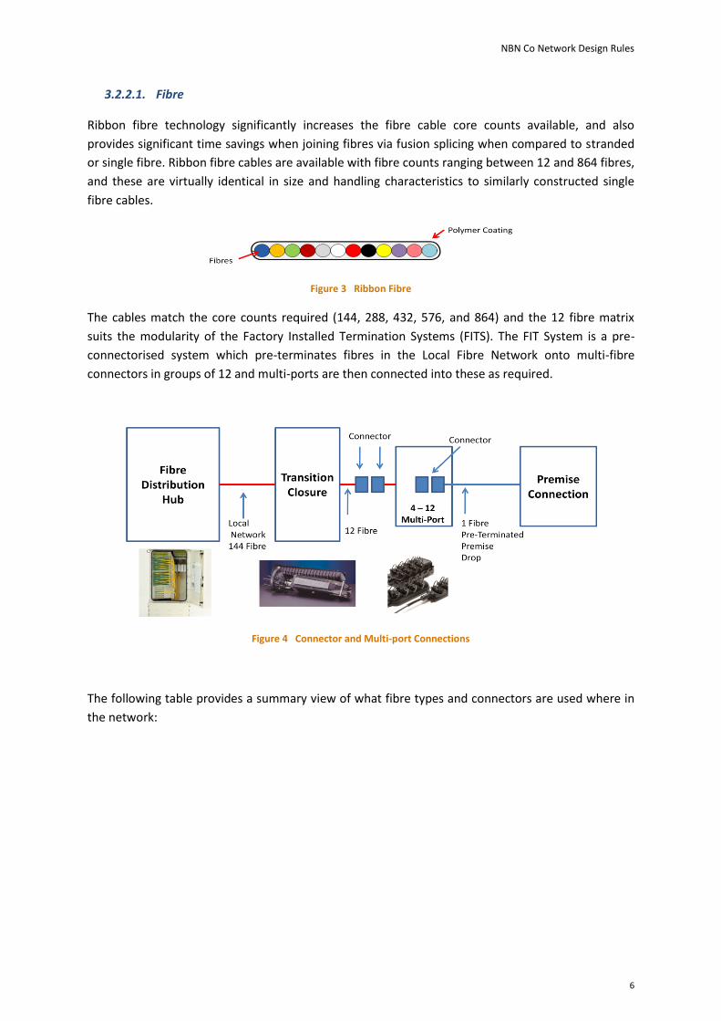
Ribbon fibre technology significantly increases the fibre cable core counts available, and also
provides significant time savings when joining fibres via fusion splicing when compared to stranded
or single fibre. Ribbon fibre cables are available with fibre counts ranging between 12 and 864 fibres,
and these are virtually identical in size and handling characteristics to similarly constructed single
fibre cables.
Figure 3 Ribbon Fibre
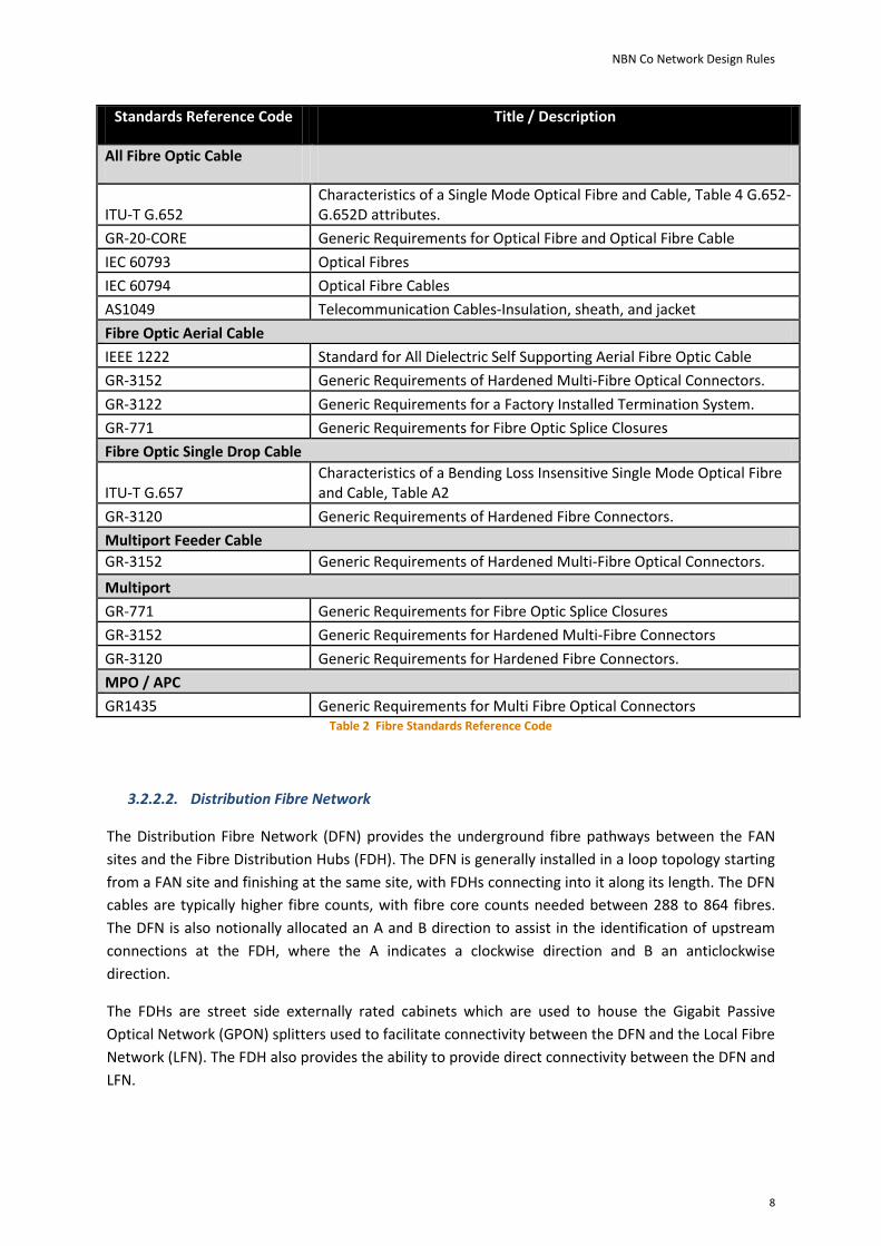
The cables match the core counts required (144, 288, 432, 576, and 864) and the 12 fibre matrix
suits the modularity of the Factory Installed Termination Systems (FITS). The FIT System is a pre-
connectorised system which pre-terminates fibres in the Local Fibre Network onto multi-fibre
connectors in groups of 12 and multi-ports are then connected into these as required.
Figure 4 Connector and Multi-port Connections
The following table provides a summary view of what fibre types and connectors are used where in
the network:

NBN Co Network Design Rules
7
Network Fibre
Type
Connectors Standards Reference (see Table 2
below)
DFN Ribbon Splice All Fibre Optic Cable
LFN Ribbon Splice: FDH (72) Tail to factory installed patch panel
Connector: FDH Patching = SC/APC
Splice: FDH Tail (e.g. 576) to Multiport Tail (12)
Connector: Multiport tail = 12 fibre tether optical connector (proprietary format)
Connector: Multiport Single Customer Connection = single fibre optical connector (proprietary format)
All Fibre Optic Cable
LFN Ribbon – Aerial
Splice: FDH Tail (e.g. 576) to Aerial Cable
Splice: Aerial Cable to Multiport Tail (12)
Connector: Multiport tail = 12 fibre tether optical connector (proprietary format)
Connector: Multiport Single Customer Connection = single fibre optical connector (proprietary format)
All Fibre Optic Cable
PFN – SDU
Single Fibre Drop
Splice: Single Fibre Fusion Splice to PCD & FWO
All Fibre Optic Cable +
Fibre Optic Single Drop Cable
Multiport Feeder Cable
PFN – MDU
Ribbon Splice: Internal FDH,FDT tail ,FWO
Connector: Internal FDH,FDT,FWO,NTD = SC/APC
Connector: FDT,FCD = MPO/APC
All Fibre Optic Cable +
Fibre Optic Aerial Cable
PFN – MDU
Single Fibre Drop
Splice: Single Fibre Fusion Splice to PCD All Fibre Optic Cable +
Fibre Optic Single Drop Cable
Table 1 Summary of fibre & connector types used in the network
NBN Co Network Design Rules
8
Standards Reference Code Title / Description
All Fibre Optic Cable
ITU-T G.652 Characteristics of a Single Mode Optical Fibre and Cable, Table 4 G.652-G.652D attributes.
GR-20-CORE Generic Requirements for Optical Fibre and Optical Fibre Cable
IEC 60793 Optical Fibres
IEC 60794 Optical Fibre Cables
AS1049 Telecommunication Cables-Insulation, sheath, and jacket
Fibre Optic Aerial Cable
IEEE 1222 Standard for All Dielectric Self Supporting Aerial Fibre Optic Cable
GR-3152 Generic Requirements of Hardened Multi-Fibre Optical Connectors.
GR-3122 Generic Requirements for a Factory Installed Termination System.
GR-771 Generic Requirements for Fibre Optic Splice Closures
Fibre Optic Single Drop Cable
ITU-T G.657 Characteristics of a Bending Loss Insensitive Single Mode Optical Fibre and Cable, Table A2
GR-3120 Generic Requirements of Hardened Fibre Connectors.
Multiport Feeder Cable GR-3152 Generic Requirements of Hardened Multi-Fibre Optical Connectors.
Multiport
GR-771 Generic Requirements for Fibre Optic Splice Closures
GR-3152 Generic Requirements for Hardened Multi-Fibre Connectors
GR-3120 Generic Requirements for Hardened Fibre Connectors.
MPO / APC
GR1435 Generic Requirements for Multi Fibre Optical Connectors Table 2 Fibre Standards Reference Code
3.2.2.2. Distribution Fibre Network
The Distribution Fibre Network (DFN) provides the underground fibre pathways between the FAN
sites and the Fibre Distribution Hubs (FDH). The DFN is generally installed in a loop topology starting
from a FAN site and finishing at the same site, with FDHs connecting into it along its length. The DFN
cables are typically higher fibre counts, with fibre core counts needed between 288 to 864 fibres.
The DFN is also notionally allocated an A and B direction to assist in the identification of upstream
connections at the FDH, where the A indicates a clockwise direction and B an anticlockwise
direction.
The FDHs are street side externally rated cabinets which are used to house the Gigabit Passive
Optical Network (GPON) splitters used to facilitate connectivity between the DFN and the Local Fibre
Network (LFN). The FDH also provides the ability to provide direct connectivity between the DFN and
LFN.

NBN Co Network Design Rules
9
The DFN is also required to provide diverse pathways for point to point services from FDHs where
required.
The DFN fibre links cable into the FDH is provided by a single cable and has both A and B directions
within the same cable sheath.
DFN Diversity
The FTTP network has been extensively modelled for availability percentages and expected
downtime due to faults and this modelling has recognized that the DFN has a significant input into
the availability calculations. This is the direct effect of the high fibre counts and distances required
for the DFN.
The availability target indicates that a link distance of 4500 metres can be applied to a single
connection pathway between the FAN and the farthest FDH or to a spur off the DFN without the
need to provide diversity. For practical purposes this distance is reduced to 4000 metres to account
for unforeseen alterations to the network in the construction phase and to provide flexibility for
future maintenance.
This calculation allows the DFN to be installed in topologies other than fully diverse.
The default position for the DFN is to provide connection diversity to each FDH for the provision of
diverse services and to provide the capability for a quicker Mean Time to Repair (MTTR). The quicker
MTTR is achieved through the use of the diverse path available at the FDH to move affected services
to the other “side” of the DFN effectively bypassing the affected cable link.
FDH
9
FDH
10
FDH
7
FDH
6
FDH
8
FDH
5
FDH
4
FDH
11
FDH
2
FDH
3
FDH
12
FDH
1
“A” Direction
“B” Direction
FAN
Change in direction of traffic to FDH 4 after failure
Direction of traffic to FDH 4 before failure
Figure 5 Traffic paths available when failure occurs
The second position is for a collapsible loop (referred to as a return spur) to be installed from the
main diverse DFN, up to 4000 metres, with a maximum of 2 FDHs connected into the return spur.

NBN Co Network Design Rules
10
This topology does not permit service restoration patching for the two connected FDHs when the
return spur is interrupted but does allow for restoration patching for the remainder of the DFN.
Change in direction of traffic to FDH 4 after failure
Direction of traffic to FDH 4 before failure
FDH
5
FDH
5
FDH
4
FDH
3
One cable sheath
Figure 6 Traffic paths available when failure occurs on return spur
The third and least optimum deployment is for a spur in which only one pathway (either A or B and
referred to as a single spur) is presented to the FDHs. This topology will only be used within
temporary conditions, such as Greenfield developments in which the development is out of synch
with the DFN build. The proviso to this option is that the DFN must be amalgamated into the DFN as
either a fully diverse DFN or return spur to meet the distance and FDH counts.
DFN Connectivity
The DFN is preferably installed underground, and by exemption aerially and is designed in a ring
topology starting and finishing at the same FAN site. This effectively divides the DFN cable ring into
an ‘A’ and a ‘B’ side.
The DFN provides connectivity to the Fibre Distribution Hubs (FDH) located within the FSAM
modules and provides two diverse fibre pathways back into the FAN site for each FDH (refer to
Figure 5).
Any individual DFN ring cable will be separated from any other portion of the same ring by the most
practically achievable distance. Multiple cables from different DFN ring cables can share the same
duct-line, as well as sharing duct-lines with TFN and LFN cables.
Fibre Distribution Hubs are connected to the DFN ring cables and each FDH is allocated fibres in both
A and B directions towards the FAN site. This ring allocation provides a diverse pathway for end-user
connectivity and allows for temporary service restoration when required. In the event of a serious
NBN Co Network Design Rules
11
service impacting event (e.g. Cable cut etc.,) the services that are connected to the affected side can
be manually re-patched at the FDH and FAN site to the diverse pathway.
Therefore the DFN network must be capable of servicing these connections in both directions of the
DFN within the optical constraints.
Whilst the DFN provides diversity from each FDH this diversity is not transferred into the LFN (the
LFN is a star topology) and therefore the DFN should also be designed to align with potential users of
point to point services (e.g. Banks, schools, universities, business parks) to allow the LFN to provide
the diverse links.
3.2.2.3. Fibre Distribution Hub
The Fibre Distribution Hub (FDH) is an aggregation and connection point between the Distribution
Fibre Network (DFN) and the Local Fibre Network (LFN). The FDH is available in 432, 576, and 864
LFN variants however the 576 will be the preferred choice.
The FDH is an environmentally secure passive device installed on street frontages and serves as a
centralized splitter location. The splitter modules housed within the FDH provide a one-to-many
relationship between the in-coming DFN fibres and the out-going LFN fibres. In keeping with the
requirements of the GPON equipment the splitters used are a 1:32 passive split.
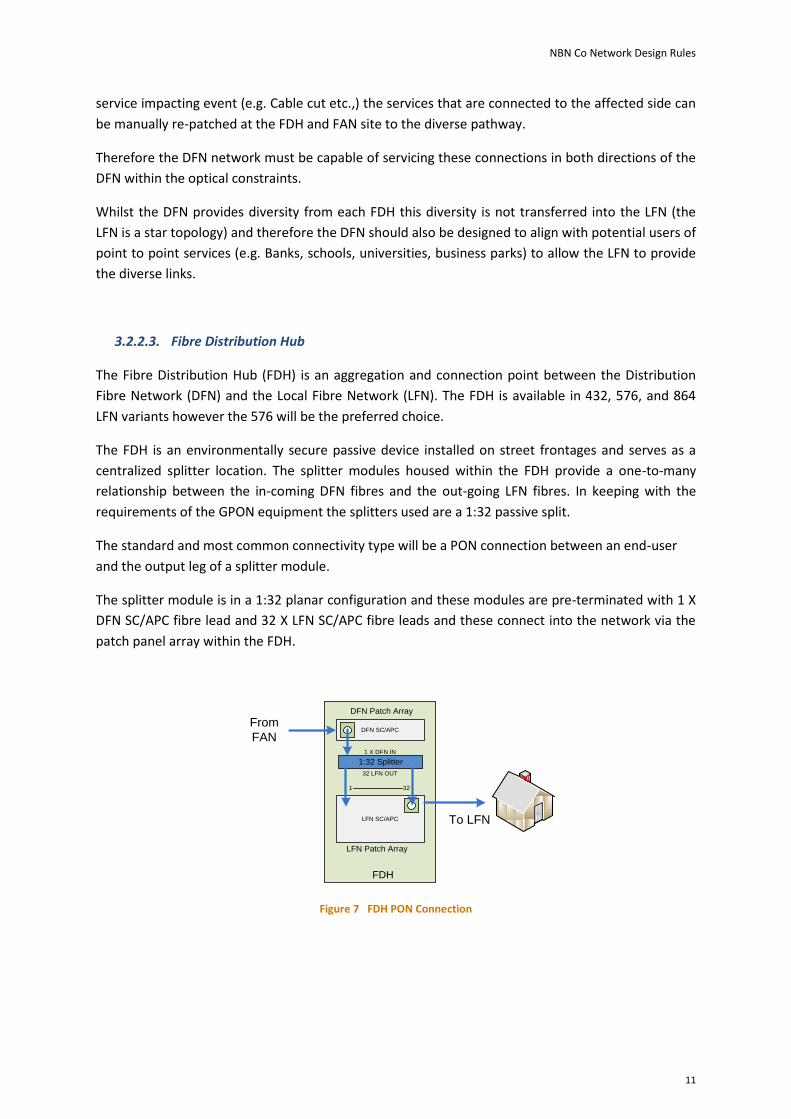
The standard and most common connectivity type will be a PON connection between an end-user
and the output leg of a splitter module.
The splitter module is in a 1:32 planar configuration and these modules are pre-terminated with 1 X
DFN SC/APC fibre lead and 32 X LFN SC/APC fibre leads and these connect into the network via the
patch panel array within the FDH.
DFN SC/APC
LFN SC/APC
DFN Patch Array
FDH
1:32 Splitter
32 LFN OUT
1 X DFN IN
From
FAN
LFN Patch Array
1 32
To LFN
Figure 7 FDH PON Connection

NBN Co Network Design Rules
12
3.2.2.4. Local Fibre Network
The Local Fibre Network (LFN) is installed from the FDH to the end-user premises in a star topology
with no inherent capacity for diversity. Diversity is achieved by extending the LFN from any other
FDH, dependant on the status of the other FDH’s location in separate geographic pathways.
LFN cables are typically smaller fibre count cables, ranging between 72 and 288 fibre counts, and are
installed in the aerial corridor and underground pathways typically alongside property boundary
street frontages. The LFN cables are presented at the FDH on a connector array to facilitate
connection to the upstream DFN either via a PON splitter or direct connection.
For an underground deployment the individual LFN cables are extended from the FDH into the Local
Fibre Network to multiple centralized splice closures (AJL) where the cables are joined into smaller
fibre count “tether” cables via splicing. The tether cable is factory terminated on one end only with
an environmentally hardened multi-fibre connector and is installed between the AJL and local fibre
pits where they provide a connection point for the factory terminated Multi-Ports (MPT). Service
fibre drops to end user premises are connected into the MPTs as required.
For aerial deployment the LFN is a factory installed termination system (FITS) that utilizes factory
installed splice closures, referred to as overmoulds, to present the multi-fibre connector at each
required location. The MPTs are then connected in a similar manner as the underground method.
Single Dwelling Unit and Non Addressable Allocations
Each SDU is allocated one fibre in the LFN between the MPT and the FDH. This fibre is utilized for the
service connection. A second fibre is allocated to the same Multiport location that the SDU will
connect to and although allocated is available for any use at the MPT for any non-addressable
connections, extra connections per SDU etc.
Non Addressable locations can be identified as locations without a physical address e.g. power
transformers, traffic light controllers etc.
Extra fibres shall be allocated to provide future capacity. In total the effective allocation on average
is three fibres per premises.
Multi- Dwelling Unit Allocations
The fibre allocations within MDUs are based on using the external FDH as the centralized splitter
location and to use these splitters and the fibres in the LFN to facilitate connections. Therefore
internal splitters within MDUs are used when there are above 110 connections required and the FDH
is then connected into the DFN. Splitters connected to the LFN should only be used for network
augmentation when the LFN is at, or near, full capacity.

NBN Co Network Design Rules
13
MDUs are classified into the following categories:
Classification Actual Premises Count
Very Small 2 - 10
Small 10-30
Medium 30-60
Large 60-110
FDA 110+ Table 3 MDU Classifications
Fibre allocations for MDUs are based on an assumption that the lower number in the actual
premises count will generally be horizontal or “garden” MDUs (e.g. a set of detached dwellings
grouped around a central driveway) and may also be semi-detached housing. This classification
would also apply to semi-detached MDUs within a community, for example a rest-home or similar.
For this example the same fibre allocation applied to SDU (3 fibres) will be applied.
For the range of MDUs from Small to Large, if contained within the same building or in close vicinity,
a ratio of 1.5 fibres per residential dwelling is used. This can be applied as having 1 fibre for initial
connection and the remaining fibres available for use for building services or future non-addressable
locations.
For FDA sized MDUs the fibre allocation is consistent with the 1.5 fibres per residential premise
however the FDH requires connection to the DFN.
For commercial buildings an allocation of 6 fibres per floor shall be applied and the LF Network
should be designed so as to be able to provide any diverse connection requirements.
Classification Actual Premises Count Fibre Allocations
Very Small 2 – 10 2 per SDU
Small 10-30 1.5 per SDU
Medium 30-60 1.5 per SDU
Large 60-110 1.5 per SDU
FDA 110+ 1.5 per SDU
Commercial Per Floor 6 per floor Table 4 MDU Fibre Allocation:
Extra fibres shall be allocated as required for any specific connections (in building services, lift
phones etc.,) or for future capacity.

NBN Co Network Design Rules
14
3.2.2.5. PON Planning Hierarchy
For planning, design, and construction purposes the network is divided into hierarchical modules
and network entities.
These modules are used to provide the planning constructs needed to provide connectivity between
the individual End-Users premise through to the Access Seeker (AS) Point of Interconnection (POI)
The first identifiable connection point is an end-user premise. These are defined as physical address
points. Each individual dwelling unit is required to have a unique service location, and is identified as
an end-user. If the end-user premise is situated in a Multi-Dwelling unit environment then these are
treated as individual connections.
The first module is the Fibre Distribution Area (FDA) which is comprised of an average of 200 end-
users. The FDA is the catchment area of a Fibre Distribution Hub (FDH) which provides a passive
optical aggregation point for the LFN into the DFN.
FIBRE DISTRIBUTION AREA
(FDA)
X 200
Figure 8 Fibre Distribution Area
The second module is the combination of a maximum of 16 FDAs to create a Fibre Serving Area
Module (FSAM). An FSAM with the maximum of 16 FDAs will, as a result, have an average catchment
of 3200 end-users.

NBN Co Network Design Rules
15
FIBRE DISTRIBUTION
AREA
(FDA)
X 2009
FIBRE DISTRIBUTION
AREA
(FDA)
X 20010
FIBRE DISTRIBUTION
AREA
(FDA)
X 2003
FIBRE DISTRIBUTION
AREA
(FDA)
X 2004
FIBRE DISTRIBUTION
AREA
(FDA)
X 20011
FIBRE DISTRIBUTION
AREA
(FDA)
X 20012
FIBRE DISTRIBUTION
AREA
(FDA)
X 20013
FIBRE DISTRIBUTION
AREA
(FDA)
X 2005
FIBRE DISTRIBUTION
AREA
(FDA)
X 2002
FIBRE DISTRIBUTION
AREA
(FDA)
X 2007
FIBRE DISTRIBUTION
AREA
(FDA)
X 2001
FIBRE DISTRIBUTION
AREA
(FDA)
X 2008
FIBRE DISTRIBUTION
AREA
(FDA)
X 2006
FIBRE DISTRIBUTION
AREA
(FDA)
X 20014
FIBRE DISTRIBUTION
AREA
(FDA)
X 20015
FIBRE DISTRIBUTION
AREA
(FDA)
X 20016
Figure 9 Fibre Serving Area Module Example
The modular size of the FSAM is dependent on the geography of the area to be served and can be
constructed with any number of FDHs.
The maximum design shall allow for the grouping of 16 FDAs onto a single DFN cable. This grouping
can contain between 13 and 16 FDAs and for this the DFN requires two loops, an inner and an outer
loop, and these are used to provide connectivity of a maximum of 16 FDHs. The inner loop as shown
in figure 6 is used for FDHs 1-8 and the outer loop for 9-16. The cable links between FDA 3 back to
the FAN and FDA 8 back to the FAN is a 576 fibre cable split evenly across the two rings at the splice
closures located in FDA 3 and FDA 8.
FDA 1
FDA 2
FDA 3 FDA 4 FDA 5
FDA 6FDA 7
FDA 8
FDA 9 FDA 10 FDA 11 FDA 12
FDA 13
FDA 14
FDA 15FDA 16
Outer Loop
Inner Loop FDH
FANSplice Closure
Figure 10 16 X FSAM Distribution Cable Connectivity

NBN Co Network Design Rules
16
For an FSAM containing 12 FSAMs or less the DFN is a single ring with the same size cable sheath
installed between FDAs back to the FAN.
FDA 12
FDA 1 FDA 2 FDA 5
FDA 8FDA 11
FDA 10
FDA 3 FDA 4
FDA 6
FDA 7
FDA 9
DFN Loop
FDH
FAN
Figure 11 12 X FSAM Distribution Cable Connectivity
The DFN cable size also alters dependant on the number of FDHs within the FSAM:
Number of FDAs per FSAM DFN Cable Size
1 288
2 288
3 288
4 288
5 288
6 288
7 288
8 288
9 432
10 432
11 432
12 432
13 576 ( Two loops of 288)
14 576 ( Two loops of 288)
15 576 ( Two loops of 288)
16 576 ( Two loops of 288)
Table 5 12 FDH FSAM Fibre Requirements per FDH

NBN Co Network Design Rules
17
FIBRE
DISTRIBUTION
AREA
(FDA)
X 2009
FIBRE
DISTRIBUTION
AREA
(FDA)
X 20010
FIBRE
DISTRIBUTION
AREA
(FDA)
X 2003
FIBRE
DISTRIBUTION
AREA
(FDA)
X 2004
FIBRE
DISTRIBUTION
AREA
(FDA)
X 20011
FIBRE
DISTRIBUTION
AREA
(FDA)
X 20012
FIBRE
DISTRIBUTION
AREA
(FDA)
X 20013
FIBRE
DISTRIBUTION
AREA
(FDA)
X 2005
FIBRE
DISTRIBUTION
AREA
(FDA)
X 2002
FIBRE
DISTRIBUTION
AREA
(FDA)
X 2007
FIBRE
DISTRIBUTION
AREA
(FDA)
X 2001
FIBRE
DISTRIBUTION
AREA
(FDA)
X 2008
FIBRE
DISTRIBUTION
AREA
(FDA)
X 2006
FIBRE
DISTRIBUTION
AREA
(FDA)
X 20014
FIBRE
DISTRIBUTION
AREA
(FDA)
X 20015
FIBRE
DISTRIBUTION
AREA
(FDA)
X 20016
FIBRE
DISTRIBUTION
AREA
(FDA)
X 2009
FIBRE
DISTRIBUTION
AREA
(FDA)
X 20010
FIBRE
DISTRIBUTION
AREA
(FDA)
X 2003
FIBRE
DISTRIBUTION
AREA
(FDA)
X 2004
FIBRE
DISTRIBUTION
AREA
(FDA)
X 20011
FIBRE
DISTRIBUTION
AREA
(FDA)
X 20012
FIBRE
DISTRIBUTION
AREA
(FDA)
X 20013
FIBRE
DISTRIBUTION
AREA
(FDA)
X 2005
FIBRE
DISTRIBUTION
AREA
(FDA)
X 2002
FIBRE
DISTRIBUTION
AREA
(FDA)
X 2007
FIBRE
DISTRIBUTION
AREA
(FDA)
X 2001
FIBRE
DISTRIBUTION
AREA
(FDA)
X 2008
FIBRE
DISTRIBUTION
AREA
(FDA)
X 2006
FIBRE
DISTRIBUTION
AREA
(FDA)
X 20014
FIBRE
DISTRIBUTION
AREA
(FDA)
X 20015
FIBRE
DISTRIBUTION
AREA
(FDA)
X 20016
FAN
Figure 12 Fibre Serving Area (FSA)
The third module is the Fibre Serving Area (FSA) and is the combination of a number of FSAM
modules located centrally around a Fibre Access Node.
The Fibre Serving Area is (FSA) linked to a Fibre Access Node (FAN) and is comprised of multiple
FSAMs linked into the FAN via the DFN cables.
The placement of the FAN site in relation to the FSAMs is derived by identifying as central a location
as practical.
The FSA is increased by adding FSAM modules as required. The optical return path for the DFN needs
to be identified and monitored during the planning and design phase per FSAM to keep the DFN ring
within the optical constraints.
3.2.2.6. Optical Budget
The optical budget allocation provides the most significant design constraint of the DFN and LFN
Network. The combination of fibre strand attenuation, splice losses, passive optical splitters,
connectors, and operating headroom provide an optical limitation on the distance between the
Optical Line Terminals (OLT) located in FAN sites and the GPON NTD located at end-user premises.
This is further constrained by the requirements of the Distribution Fibre Network to provide a
diverse path for any FDH within the optical budget constraints.
The limitations are based on the optical equipment transmit and receive parameters which are set
via the optical devices as referenced in the Gigabit Passive Optical Network (GPON) standard ITU-T

NBN Co Network Design Rules
18
G.984, and this equates to a maximum permissible optical loss of 28dB or a permissible distance of
15,000 meters, whichever is less, between the OLT and GPON NTD. This optical loss is calculated for
the worst case combination of OLT and GPON NTD connection within an FDA and is applied to both
the A and B direction. The average optical losses used for detailed design optical budget calculations
are listed in table 1.
Event Optical Loss
Single Fibre Strands (DFN and LFN) 0.34dB/km @ 1310nm , 0.22dB/km @ 1550nm
Fusion Splice 0.10dB
Mated SC/APC Connector 0.30 dB
1:32 Passive Optical Splitter (without connectors) 16.7 dB
Mated 12 Fibre Multi-Fibre Connector Environmentally Hardened
0.60 dB
Mated SC/APC Connector Environmentally Hardened
0.50 dB
Table 6 Maximum Optical Loss
The calculation of the optical loss is performed with the following equation:
(DFN Distance (in km) x 0.35dB) + (DFN planned splices x 0.10dB) + (FDH Optical Splitter Loss) +
(2 X mated connector (at FDH)) + (LFN Distance (in km) x 0.35) + (LFN splices x 0.10dB) + (multi-
fibre connector loss) + (mated environmentally hardened SC/APC connector) + (2 x mated
SC/APC connectors).
3.2.3. OLT
The GPON Optical Line Terminator function terminates multiple individual Gigabit Passive Optical
Network (GPON) connections, each with a number of ONTs attached. The GPON Optical Line
Termination (OLT) supports up to 128 GPON interfaces per shelf, with each GPON interface
extending to one or more Fibre Serving Areas for connectivity to end-users. GPON interfaces are
arranged in groups of 8 per Line Terminating card (LT).
The GPON OLT system supports dual Network Termination (NT) cards for control and forwarding
redundancy, and 4 x 10 Gigabit Ethernet (SFP+) network uplinks per NT for network connectivity.
The system is fed by -48VDC power, and power module/feed redundancy is incorporated into the
shelf.
The OLT is located in Fibre Access Node (FAN) sites. To support Greenfields sites where a FAN site
has not yet been established a cabinetised OLT solution is deployed, known as a Temporary FAN
(TFAN).
NBN Co Network Design Rules
19
3.3 Point to point Fibre Access Domain
There is no defined solution for point to point based customer services, but fibre has been deployed
to support this in the future.
3.3.1. Fibre
The fibre selected is designed to support both GPON and point to point services. Refer to GPON DFN
section.
3.3.2. Distribution Fibre Network
The DFN is designed to support both GPON and point to point services. Refer to GPON DFN section.
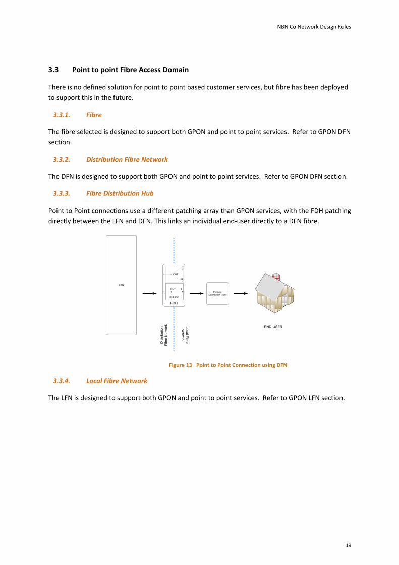
3.3.3. Fibre Distribution Hub
Point to Point connections use a different patching array than GPON services, with the FDH patching
directly between the LFN and DFN. This links an individual end-user directly to a DFN fibre.
Premise
Connection Point
FAN
Lo
ca
l Fib
re
Ne
two
rk
Dis
trib
utio
n
Fib
re N
etw
ork
1
32
OUT
FDH
END-USER
1OUT
BYPASS
Figure 13 Point to Point Connection using DFN
3.3.4. Local Fibre Network
The LFN is designed to support both GPON and point to point services. Refer to GPON LFN section.

NBN Co Network Design Rules
20
3.4 TD-LTE Wireless Access Domain
The Wireless Access domain solution consists of the following components:
Wireless Network Terminating Device (WNTD) - The Wireless Network Terminal located
at the end-user premises uses TD-LTE technology to connect back to the eNodeB. It
delivers UNI-D capabilities to a premise.
Radio Spectrum – NBN Co has radio spectrum to support the TD-LTE radio technology in
line with the 3GPP specification
eNodeB – provides the radio access interface for the WNTDs
Aggregation and Transport for Wireless –
o Microwave equipment is used to backhaul and where appropriate, aggregate traffic
from eNodeBs back to a FAN site
o FAN Aggregation switch may be used in a FAN site to further aggregate traffic from
eNodeBs before entering the Transport solution
o Transport - provides the carriage between the FAN site and a further aggregation
switch located in the POI site. Common infrastructure used for all connectivity
between FAN and POI sites
o POI Aggregation Switch is used in the POI site to aggregate the traffic from the FANs
before entering the PDN-GW. This is common infrastructure that provides the
Aggregation Domain EAS/ECS functions as well.
The PDN-GW - provides policy and admission control for the WNTDs. It also provides the
interface to the Aggregation Domain for the aggregated Wireless Access traffic.
WNTD Wireless Network Terminating Device
eNodeB Base Station
PDN-GW Packet Data Network GateWay
UNI-D NNI
WNTD eNodeBuWave
TransportFAN Agg.
SwitchTransport(Common)
POI Agg. Switch
(Common)
PDN-GW
Figure 14 High level interconnection block diagram of Wireless Access
NBN Co Network Design Rules
21
3.4.1. Wireless NTD (WNTD)
The WNTD terminates the incoming radio signal at the end-user premises and provides one or more
User to Network Interfaces (UNI).
The WNTD consists of the following two physical components: an Indoor Unit (IDU) and an Outdoor
Unit (ODU), connected together with a Cat 5 cable.
The ODU key components include:
Cross-polar panel antenna
LTE TRx and modem
Interface to the IDU
The IDU key components include:
4 UNI-D ports,
Switch
Interface to the ODU
A standard AC power supply is used to power the IDU and through that the ODU.
3.4.2. Radio Spectrum
NBN Co will use its holdings in the 2.3 GHz spectrum band in its deployment of Wireless Access
Services in the 2015 timeframe.
The NBN Co spectrum holding in the 2.3 GHz band is defined by the ACMA in:
http://web.acma.gov.au/pls/radcom/client_search.client_lookup?pCLIENT_NO=1104329
http://web.acma.gov.au/pls/radcom/client_search.client_lookup?pCLIENT_NO=8129031
Generally the spectrum held by NBN Co Limited was purchased in the spectrum auction while the
spectrum held by NBN Co Spectrum Pty Ltd was purchased from AUSTAR.
A licence number in the table links to the licence details, including a Licence Image. The Licence
Image defines, among other technical requirements, the exact geographic area covered by the
licence.
3.4.3. eNodeB (Base Station)
Each eNodeB has three sectors and is sited according to a site specific radio coverage plan to provide
optimised coverage. Each sector supports a maximum of 60 end users, with an approximate CIR for
the eNodeB of 100Mbps. Some sites have existing sheltered accommodation available, while other
sites will have none. Where none is available an environmentally protected housing will be provided
to house the equipment.
The eNodeB provides the Air (Radio) Interface which connects the eNodeB to the WNTD, and a
backhaul Interface which connects the eNodeB to the Microwave Backhaul equipment. The eNodeB
comprises a number of interconnected modules:

NBN Co Network Design Rules
22
3 RF Antennae
GPS Antenna
Remote Radio Unit
Digital Baseband Unit
Power Supply
Battery Backup
3.4.4. Aggregation and Transport for Wireless
3.4.4.1. Microwave Transport Equipment
Microwave Transport equipment is used where an eNodeB site does not have access to direct fibre
tail to connect to a FAN site. Microwave Transport equipment is housed in the eNodeB cabinet. The
Microwave Antenna is mounted on the radio tower where the eNodeB RF Antennas are mounted.
Microwave Transport equipment is also used to connect an eNodeB spur using a Microwave End
Terminal to a Microwave Hub Site.
A Microwave Hub Site is located with an eNodeB. The Microwave Transport equipment at a hub site
will communicate with up to four Microwave End Terminals, and provide an aggregate point for
connectivity with another Microwave End Terminal located as close as possible to a FAN site. The
maximum bandwidth achievable is 900Mbps, allowing for the aggregation of up to 8 eNodeBs.
Microwave Hub sites can be connected to other Microwave Hub sites, as long the final Hub to end
terminal bandwidth does not exceed an aggregate of eight eNodeBs.
The exact number of eNodeB spurs that are connected back to a Microwave Hub, and the location of
the Microwave End Terminal to connect to the FAN site is heavily dependent on local geography and
end user distribution.
Example deployment scenarios are shown in the diagram below:

NBN Co Network Design Rules
23
1GE
1GE
900Mbps max
100Mbps CIR
100Mbps CIR
100Mbps CIR
1GE
100Mbps CIR
100Mbps CIR
1GE
100Mbps CIR
100Mbps CIR
FAN Site
eNodeB
Microwave
Terminal SiteHub Site
eNodeB
Microwave
Terminal Site
eNodeB
Microwave
Mini Hub Site
eNodeB
Microwave
Terminal Site
eNodeB
Microwave
Terminal Site
eNodeB
Microwave
Terminal Site
eNodeB
Microwave
Terminal Site
eNodeB
Microwave
Terminal Site
eNodeB
Microwave
Terminal Site
eNodeB
Microwave
Hub Site
eNodeB
Microwave
Hub Site
eNodeB
Microwave
Optically Fed
Terminal Site
eNodeB
Microwave
Repeater Site
Microwave
Microwave
Fibre
eNodeB
Three sector base station
Microwave
Microwave Equipment
Figure 15 Microwave Transport Design
3.4.4.2. Fibre Transport Equipment
Where an eNodeB site has access to a direct fibre tail to connect to a FAN site a switch function is
housed in the eNodeB cabinet to enable connectivity from the eNodeB to the fibre. The CIR of just
over 100Mbps is applied for consistency with eNodeBs connected via Microwave Transport.
3.4.4.3. FAN Aggregation Switch
The FAN Aggregation Switch may be deployed on its own or in pairs for resiliency. They are located
in FAN sites where aggregation for up to 18 Microwave Hub sites, eNodeBs that are connected
directly to the FAN site via a direct fibre tail, and/or where traffic shaping is required to integrate to
the Transport Domain.
3.4.4.4. Transport
Transport from the FAN to the POI is provided by either 3rd party backhaul or NBN Co’s DWDM
solution. Refer to the Transport Domain section for further information.

NBN Co Network Design Rules
24
3.4.4.5. POI Aggregation Switch
The POI Aggregation Switch is deployed in pairs in POI sites to aggregate the Wireless Access traffic
from FAN sites. The switches are shared infrastructure, providing both this function and the
function of the Ethernet Access Switch (EAS) of the Aggregation Domain.
3.4.5. Packet Data Network Gateway (PDN-GW)
The PDN-GW supports up to 25000 WNTDs. It is provided as a pair for resiliency, each with its own
internal resiliency of controller, traffic and line cards.
The PDN-GW has 2 4 x 10 Gigabit Ethernet (SFP+) interfaces to the Aggregation Domain for resilient
network connectivity, and 2 4 x 10 Gigabit Ethernet (SFP+) interfaces to the POI Aggregation Switch
pair for resilient network connectivity. The system is fed by -48VDC power, and power module/feed
redundancy is incorporated into the shelf.
3.4.6. Wireless Access Planning Hierarchy
For planning, design, and construction purposes the network is divided into hierarchical modules
and network entities.
These modules are used to provide the planning constructs needed to provide connectivity between
the individual End-Users premise through to the Access Seeker (AS) Point of Interconnection (POI)
The first identifiable connection point is an end-user premises. These are defined as physical address
points. Each individual dwelling unit is required to have a unique service location, and is identified as
an end-user.
The first module is the Base Station Sub-cluster Module. Three sector eNodeBs provide adjacent or
overlapping coverage and are grouped in clusters of up to eight sites.
The maximum number of active dwellings in a sector is 60 dwellings (this may vary depending on the
exact positions and radio conditions of the served dwellings.
The three sectors of an eNodeB (maximum of 180 end users) typically provide an aggregated CIR
throughout of approximately 100 Mbps. This determines the Microwave Transport backhaul
capacity required.
The maximum bandwidth achievable for the Microwave hub back to a FAN site is 900Mbps, allowing
for the aggregation of up to 8 eNodeBs, with a maximum of 1440 end users.

NBN Co Network Design Rules
25
BASE STATION CLUSTER
BSC
X 1440
X 8
Figure 16 Base Station Sub-Cluster
The second module is the Wireless Serving Area Module. All Base Station Clusters connected to a
common FAN site are grouped into a Wireless Serving Area Module. The largest WSAM will have up
to 24 Base Station Clusters connecting to a FAN.
FAN
WIRELESS SERVING AREA
MODULE (WSAM)
BASE STATION CLUSTER
BSC
X 1440
X 8
BASE STATION CLUSTER
BSC
X 1440
X 81 24
Figure 17 Wireless Serving Area Module
The third module is the Wireless Serving Area (WSA). All the Wireless Serving Area Modules
connected to a common POI (the location of the PDN-GWs) are grouped into a Wireless Serving
Area. The maximum number of WSAMs in a WSA is determined by the number of FANs that connect
back to the POI. For the purposes of wireless dimensioning, the size of a WSA is based on the
maximum number of end users, rather than the maximum number of WSAMs, with a maximum of
25000 end users in a WSA.

NBN Co Network Design Rules
26
3.5 Satellite Access
The Satellite Access solution is currently under development. This section provides an indicative
network design based on the requirements NBN Co has used during the on-going procurement
process. The final design adopted as a result of this process may differ in some details to that
described in this section. However, any such changes will be as a result of a competitive tender
process that will identify the best value for money approach that can be delivered consistent with
the overall indicative network design.
The Satellite Access domain solution consists of the following components:
Satellite NTD (Very Small Aperture Terminals or VSATs) - The Satellite Network Terminal
located at the end-user premises communicates over the satellite RF links back to the VSAT
baseband sub-system. It delivers UNI-D capabilities to a subscriber premises.
Satellite – two, multi-spot beam, geostationary, "bent-pipe”, telecommunications satellites
to connect VSATs to the VSAT Baseband sub-system. Located in orbital slots overlooking
Australia and operating in the Ka-band RF spectrum.
RFGW – RF Gateway Facility supporting the RF, VSAT Baseband and Service Control Sub-
Systems.
RF Sub-System – Earth station RF antennas, transmission and reception equipment to
provide trunk links to and from the satellites.
VSAT Baseband Sub-System – subscriber service termination equipment to manage and
carry user traffic to and from Satellite subscribers.
Service Control – Satellite specific user application and traffic management equipment to
enhance the user experience due to the long latencies incurred over geostationary satellite
links.
RFGW
UNI-D
SatelliteRF Sub-system
VSAT Baseband
Sub-System
Service Control
VSAT(Very Small
Aperture Terminal)
Figure 18 High level interconnection block diagram of Satellite Access
3.5.1. Satellite NTD (Very Small Aperture Terminal (VSAT))
The VSAT is located in the user premise and provides the User to Network Interfaces (UNI-D) and
connects to the NBN Co network via the satellite over Ka-band RF spectrum.
The VSAT consists of the following two physical components: an Indoor Unit (IDU) and an Outdoor
Unit (ODU), connected together with a coaxial cable.

NBN Co Network Design Rules
27
The ODU key components include:
Parabolic satellite terminal antenna
Ka-Band VSAT transceiver
Interface to the IDU
The IDU key components include:
4 UNI-D ports,
Switch
Embedded Transparent Performance Enhancing Proxy (TPEP) software client
Interface to the ODU
A standard AC power supply is used to power the IDU and through that the ODU.
3.5.2. Satellite
3.5.2.1. Systems Engineering Design
NBN Co is building two, multi-spot beam, geostationary, "bent-pipe”, Ka-band, telecommunications
satellites for the Satellite Access Solution with the following characteristics:
Two satellites to enable service redundancy and load balancing of users.
Multi-spot beam design to enable the system capacity to support 3% of the Australian
population and the optimum broadband user experience from the amount of RF spectrum
available.
Geostationary locations to enable full coverage of the Australian mainland and territories
with the least number of satellites and at the lowest possible VSAT costs.
“bent-pipe” design, meaning the satellite is only an RF transceiver for network to user traffic
and user to network traffic, providing support for broadband services to 3% of the Australian
population with minimum mass of the spacecraft.
Ka-band operation to achieve the user experience speeds and the required system capacity
from 2 satellites.
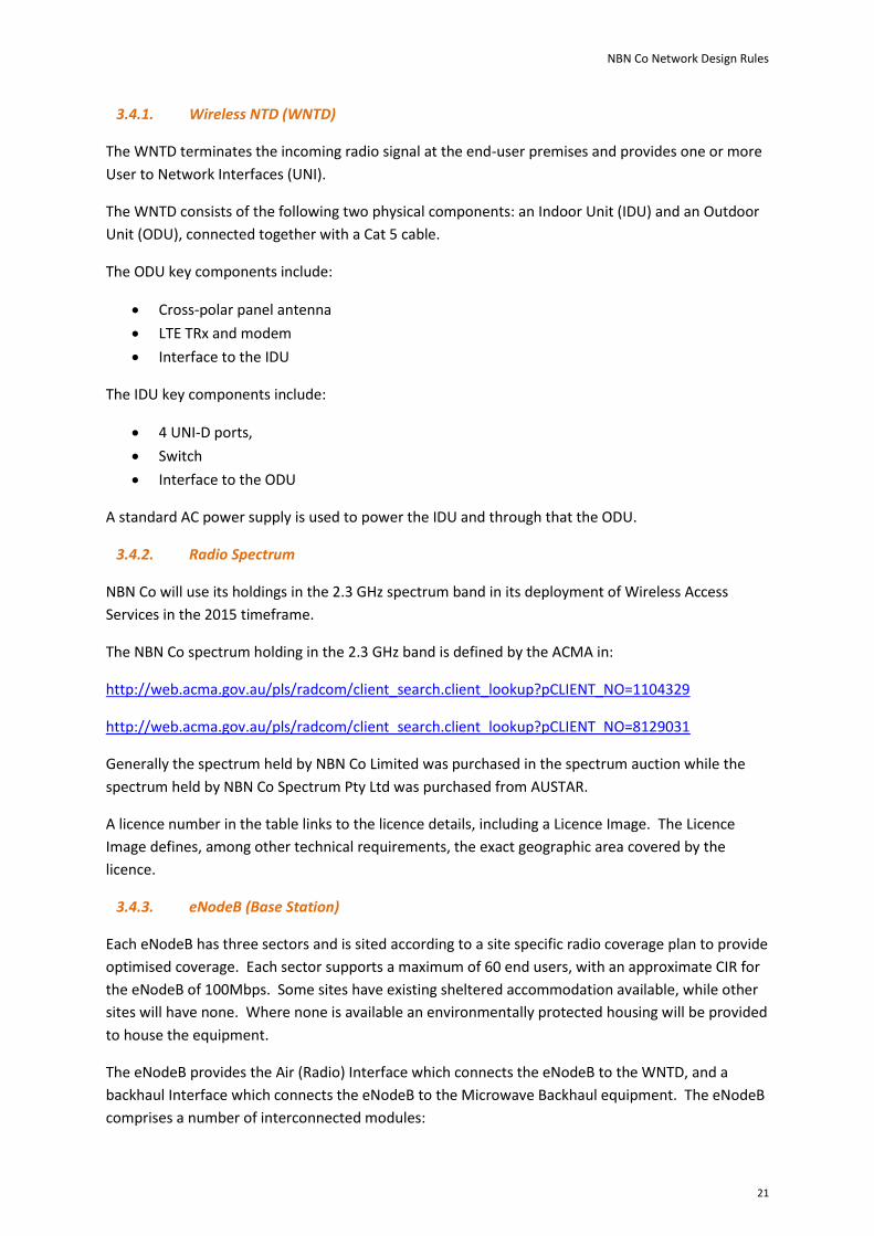
The “satellite - user” spot beams are designed to achieve the system capacity requirements for the
last 3% of population, by re-using the Ka frequency band as efficiently as possible. This is achieved
through the combination of:
Optimized placement of user spot beams
Frequency re-use and polarity re-use of the Ka-band spectrum
Highly directional satellite and VSAT antennas to minimize interference
Optimized RF filter designs to achieve the highest order modulation techniques over satellite
links.
NBN Co Network Design Rules
28
Figure 19 Preliminary Design of User Spot Beams
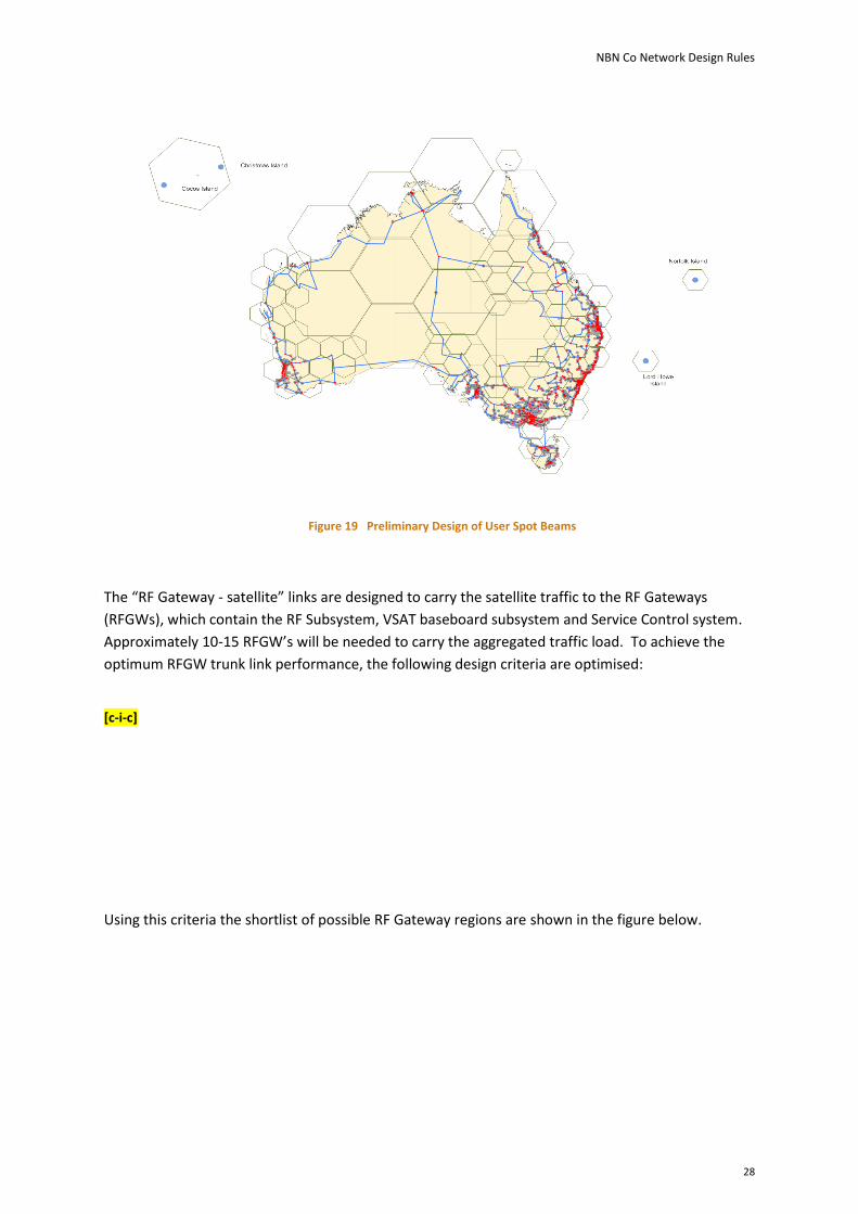
The “RF Gateway - satellite” links are designed to carry the satellite traffic to the RF Gateways
(RFGWs), which contain the RF Subsystem, VSAT baseboard subsystem and Service Control system.
Approximately 10-15 RFGW’s will be needed to carry the aggregated traffic load. To achieve the
optimum RFGW trunk link performance, the following design criteria are optimised:
[c-i-c]
Using this criteria the shortlist of possible RF Gateway regions are shown in the figure below.

NBN Co Network Design Rules
29
[c-i-c]
Figure 20 Shortlisted RF Gateway Regions
3.5.2.2. RF Spectrum and Orbital Slots
NBN Co will use the Ka-band radio spectrum through a combination of using class licensed bands as
well as privately negotiated spectrum licenses with current license holders.
Description Frequency Range
RFGW to Satellite Uplink [c-i-c]
Satellite to VSAT Downlink [c-i-c]
VSAT to Satellite Uplink [c-i-c]
Satellite to RFGW Downlink [c-i-c]
RF Auto Tracking Downlink [c-i-c]
Uplink Power Control [c-i-c]
Table 7 Preliminary RF Spectrum Plan
The NBN Co satellites are designed to operate at the orbital slots of 140 deg E and 145 deg E. NBN
Co is currently going through the ITU domestic and international orbital slot coordination process.

NBN Co Network Design Rules
30
3.5.3. RF Sub-System
In each RF Gateway, the RF Sub-System transmits and receives RF signals with the satellites, and
connects to the VSAT baseband Sub-system. The RF Sub-system comprises of the following major
components;
[c-i-c] earth to satellite antennae on controllable mounting platforms
RF amplification, filtering, conditioning and receiving equipment operating at Ka-band.
Power Supplies
Monitoring and Control systems.
3.5.4. VSAT Baseband Sub-System
The VSAT baseband system located in the RFGWs and is the termination system for VSAT traffic and
management signals. It is composed of the following components;
Modulation and Demodulation equipment
Air Resource Management equipment
Traffic forwarding equipment
The dimensioning of each RFGW’s VSAT Baseband sub-system will be based on the aggregate
number of end-user services being terminated at the site, the most efficient RF channel packing of
the available Ka-band spectrum, the highest order modulation code points possible for transmission
and reception to and from the satellite from the specific RFGW location and the highest N to 1
equipment redundancy ratio supported by the VSAT Baseband sub-system supplier.
3.5.5. Service Control
The Service Control system is designed to enhance the user experience by intelligently accelerating
and spoofing user traffic to counteract the latency effects of the very long distances encountered
between earth to satellite, then satellite to earth RF links. Multiple Transparent Performance
Enhancing Proxy (TPEP) techniques are being used in the Satellite Access solution design;
Traffic payload and header compression and suppression
TCP traffic acceleration
Web traffic acceleration
Traffic caching and pre-fetching
The TPEP system is implemented in servers located in the NBN Co RFGW as well as embedded
software in the VSATs. No software or configuration is required by the Access Seeker or the user to
enable the TPEP functionality.

NBN Co Network Design Rules
31
3.6 Transport Domain
3.6.1. Dense Wavelength Division Multiplexing (DWDM)
The NBN Co Dense Wavelength Division Multiplexing (DWDM) fibre optic transport network is made
up of a number of DWDM Nodes (DNs) situated mainly at Point of Interconnect (POI) and Fibre
Access Node (FAN) sites, all interconnected by Optical Multiplex Section (OMS) links. A DN may also
be used within a link for amplification.
The DWDM network will predominantly provide physical connectivity and transit backhaul capacity
between POI and FAN sites. The network will also provide connectivity to centralised depots, data
centres and delivery points for the specific transport services that require them.
The following diagram shows the basic connectivity scenarios for the DWDM network. Each DN has a
metric called “degree of connectivity”, which is the number of fibre interfaces it has, and therefore
the number of other DNs it can connect to. The DN at POI 1, for instance, has a degree if two: it
connects to the DNs at two FAN sites. The DN at FAN 7 has a degree of one.
Depot/Data Centre/Delivery
Point
POI 4
FAN 3
FAN 7
FAN 6FAN 5
POI 3
FAN 4
FAN 1 FAN 2
POI 1 POI 2
DN DN
DN
DN
DN
DN DN
DNDNDN
DN
DN
DN
Optical Multiplex
Section
DN
DN
DN
Figure 21 Basic DWDM physical connectivity scenarios
There are two types of DWDM Nodes: Reconfigurable Optical Add-Drop Multiplexers (ROADMs) and
Optical Line Repeaters (OLRs). Each of these two types of DN comprises:
Baseline elements: elements that have a fixed quantity per degree and do not expand with
traffic growth unless that growth involves an increase in degrees. Such elements include
amplifiers, add/drop filters and wavelength selective switches.
Growth elements: these are elements within a degree that can be added to as growth
requires. Such elements include channel cards, controller and chassis.

NBN Co Network Design Rules
32
3.6.1.1. Reconfigurable Optical Add-Drop Multiplexers (ROADMs)
Reconfigurable Optical Add-Drop Multiplexers (ROADMs): these are one- (or more) degree nodes
that can provide the following functions:
Extract data from a wavelength on any of its degrees for presentation to a client
interface
Inject data from the client interface into a wavelength for transport on any of its degrees
Transit wavelengths between degrees
The standard ROADM variant used allows transmission up to 96 wavelengths, each wavelength in
effect a channel of 40Gbps initially, rising to 100Gbps in future network releases. Standard ROADMs
will be used at both POI and FAN sites.
A smaller, compact ROADM variant, for use where space is an issue, supports up to 8 wavelengths.
The standard and compact ROADMs can be used together: although the compact ROADM only
supports 8 wavelengths, those wavelengths can be any of the 96 produced by the standard ROADM.
Compact ROADMs will be used only at FAN sites that require a maximum of two degrees and a
maximum of 8 channels.
There is also a Long Span ROADM that is used to allow un-regenerated OMS links across Bass Strait.
The Long Span ROADM allows up to 40 wavelengths (channels).
3.6.1.2. Optical Line Repeaters (OLRs)
Optical Line Repeaters (OLRs): these are two-degree wavelength-pass-through nodes that provide
optical amplification only. OLRs may be required when transmission fibre distances between
adjacent ROADMs exceeds the optical reach of the equipment.
3.6.1.3. DWDM Network Topologies
There are four network topologies that can be deployed. In most cases the overlapping physical ring
topology will be used as the majority of dark fibre is being sourced from Telstra and only a single pair
is being provided on most routes.
Standalone Physical Rings:
Each physical ring utilises one fibre pair. Wavelength routing and count within one ring has no
dependencies on the physical attributes or traffic requirements on any other ring. If there are any
DNs common between rings, they will require a degree of more than two. Any inter-ring wavelength
connectivity will be performed via the wavelength selective switches within the common DNs.

NBN Co Network Design Rules
33
FAN
FAN
FAN
FAN
POI
FAN
FAN
FAN
FAN
FAN
FAN
POI
FAN
DN
DN
DN
DN
DN
DN
DN
DN
DN
DN
Common Nodes
Fibre Pair
DN
DN
DN
Figure 22 Standalone physical rings
The rings provide the 1+1 redundancy required between any two points in the network: if one link
should fail, any node past the breach can be reached by routing in the other direction using a
different wavelength. The re-routing can be achieved through either 1+1 Client Protection, where
the client network recognises the break and uses a second connection for traffic continuity, or 1+1
Service Protection, where the DWDM network itself provides the rerouting capability.
FANFAN
FAN
FAN FAN
POI
DNDN
Fibre Pair
DN DN
OLT
DN
DN
EAS EAS
Wavelength 2Wavelength 1
FANFAN
WAN
FAN FAN
POI
DNDN
Fibre Pair
DN DN
NodeB/MW
DN
DN
EFS
Wavelength 2Wavelength 1
1+1 Client Protection 1+1 Service Protection
Figure 23 Examples of redundancy in the DWDM network (using 1+1 Client Protection and 1+1 Service Protection)

NBN Co Network Design Rules
34
Overlapping Physical Rings:
This is the preferred topology where there are adjacent DWDM rings with shared physical routes. In
this scenario physical rings can share common fibre pairs. This means that wavelength routing and
counts within the shared links have dependencies on the physical attributes and traffic requirements
of both rings. Like the standalone deployment option, some DNs will require degrees of more than
two degrees. And again inter-ring wavelength connectivity will be performed via the wavelength
selective switches within the common DNs.
FAN
FAN FAN
FANFAN
FANFAN
POI
FAN
DN
DNDN
DN
DNCommon
Links
Fibre Pair
DN
DN
FANDN
DNDN
Figure 24 Overlapping physical rings
Point-to-Point Spur Links:
These will be used to extend ring or POI connectivity to one or more isolated FAN sites. There is a
preference to use two fibre pairs within a spur link to introduce diversity, but some spur links may be
limited to one fibre pair. Standard and compact ROADMs can both be used as the far DN in spur
links, but the DN that connects the spur to the ring must have at least three degrees, and therefore
must be a standard ROADM. OLR nodes may be required within the spur link when transmission
fibre distances between adjacent ROADM nodes exceed the optical reach.

NBN Co Network Design Rules
35
FAN FAN
FAN
FAN FAN
FAN
POI
FAN
DN
DN
DNFibre Pair
DN
DN
FAN
DNDN
FAN FAN
DN DN DN
FANFAN
DNDN
DN SpurSpur
Spur Spur
Figure 25 Point-to-point spur links
Point-to-Point Standalone Links:
Used only in the Bass Strait deployment, two point-to-point standalone links are deployed between
the Long Span ROADM nodes.
FAN
POI
FAN
FAN
FAN
POI
FAN
DN
Fibre Pair
DN
DN
Standalone LinkDN
FAN
DN
DN
FAN
POI
FAN
FAN
FAN
POI
FAN
DN
DN
DN
DN
FAN
DN
DNLong Span ROADM
Long Span ROADM
Long Span ROADM
Long Span ROADM
DN
DN
DN
DNDN DN
DN DN
Standalone Link
Figure 26 Point-to-point standalone links

NBN Co Network Design Rules
36
3.6.2. Managed Services Transmission
Managed Services are required to supplement the direct fibre and DWDM transport solutions during
the roll-out of the transit network. They may be used to provide a complete end-to-end solution or
form part of a transport service in combination with DWDM and/or direct fibre.
Managed services are supported for the following connectivity scenarios:
Fibre access transit (OLT to ECS/EAS)
Greenfields fibre access transit (OLT to ECS/EAS)
Wireless access transit (eNodeB or microwave transport to ECS/EFS)
Fibre Access Transit:
Transport is required between FAN and POI sites for the Fibre Access Service. The basic transport
using Managed Services is a pair of fully redundant (1+1) point-to-point Ethernet services running at
subrate, 1Gbps or 10Gbps speeds.
FAN POI
EAS/ECS
EAS/ECS
OLT
Managed Service
Managed Service
Figure 27 Fibre access transit
Greenfields Fibre Access Transit:
Transport is required between FAN and POI sites, much as with the standard fibre access transit. A
single unprotected managed service will be deployed.
Long Term FAN
POI
Managed Service
Managed Service
TemporaryFAN EAS/
ECS
EAS/ECS
OLT
Fibre Pair
Figure 28 Unprotected Greenfields fibre access transit

NBN Co Network Design Rules
37
Wireless Access Transit:
Wireless access transit is required between FAN and POI sites. As with the fibre access transit, the
basic transport using Managed Services is a pair of fully redundant (1+1) point-to-point Ethernet
services running at subrate, 1Gbps or 10Gbps speeds.
FAN
POI
Managed Service
Managed Service
Wireless Aggregation Equipment
POI Agg. Switch
POI Agg. Switch
Figure 29 Wireless access transit
3.6.3. Direct Fibre
Direct fibre is the underlying building block of the Transport network domain. The following
connectivity scenarios are either fully or partially supported by direct fibre:
Fibre Access Transit
Greenfields Fibre Access Transit
Wireless Transit
Fibre Access Transit:
Direct Fibre for fibre access transit is limited by the interfaces supported on the OLT. The OLT only
supports 10GBase-LR interfaces today, which limits direct fibre reach for fibre access to 10km. This is
being upgraded to support 10Gbase-ER interfaces in 2012, extending the reach to 40km.
The following direct fibre transit scenarios are supported for fibre access transit:
Direct fibre for both paths from the OLT back to the POI. This can be used when both fibre
paths are ≤10km today, or ≤40km from mid-2012.
Direct fibre on the short path from the OLT to the POI and direct fibre on the long path from
the OLT to the nearest DWDM node. This can be used when the short path is ≤10km (≤40km
from mid-2012) and the path to the nearest DWDM node is ≤10km (≤70km from mid-2012,
as both the OLT and the DWDM nodes will support 10Gbase-ZR).

NBN Co Network Design Rules
38
Greenfields Fibre Access Transit:
Direct fibre is used between the OLTs housed in temporary FAN sites and the Managed Services
interface (see Figure 27and Figure 28). Both 1000Base-LX and 1000Base-ZX interfaces are supported
allowing for fibre distances of up to 70km to be supported.
Wireless Access Transit:
Direct fibre is supported between the Wireless Access network eNodeBs and Microwave Transport
and the local FAN site. 1000Base-LZ and 1000Base-ZX interfaces are supported allowing for fibre
distances of up to 70km to be supported.

NBN Co Network Design Rules
39
3.7 Aggregation Domain
The Aggregation Domain performs fanout and aggregation of media between the Access Seekers
and the Access Domain for both the Fibre and Wireless Access Services. Aggregation Domain
network elements are exclusively deployed in Points of Interconnect sites (POIs).
For the Fibre Access Service, the majority of metropolitan Fibre Access Node (FAN) sites will also be
POI sites, where Access Seekers can connect their network equipment into the NBN Co – via the
External Network-to-Network Interface (E-NNI) – to service all end-users hosted off the FANs
associated with that POI.
In regional areas where end-user densities are lower, it will be more common for FAN sites and POI
sites to be in separate physical locations.
For the Wireless Access service, the Aggregation Domain connects locally at the POI to the Wireless
Access Domain.
The Aggregation Domain network elements are:
The Ethernet Aggregation Switch (EAS)
The Ethernet Fanout Switch (EFS)
The Ethernet Combined Switch (ECS)
3.7.1. Ethernet Aggregation Switch (EAS)
This platform is used to aggregate a number of Access Domain network interfaces and provide traffic
forwarding towards other Aggregation Domain network elements such as the EFS, or another EAS.
To support Access Domain network interface resiliency, EAS are deployed in pairs.
The EAS node is connected to its paired EAS node and to the EFS nodes using N × 10Gbps direct fibre
links, where N is 1 to 5.
N ×
10
Gb
ps
N × 10Gbps
N × 10Gbps
EFS
EFSEAS
EAS
Figure 30 Aggregation Domain interfaces on the EAS
The EAS offers redundant connectivity to the access domains via 1Gbps, 10Gbps or sub-rate bit
rates. The links can use any of the Transport Domain solutions for connectivity to remote locations

NBN Co Network Design Rules
40
(e.g. FAN sites), or direct fibre for any local connections within the POI (e.g. the PDN-GW for wireless
access).
3.7.2. Ethernet Fanout Switch (EFS)
This platform is used to aggregate a number of Access Seeker interfaces (on the External Network-
Network Interface, E-NNI) and fan out the traffic towards other Aggregation Domain network
elements such as the Ethernet Aggregation Switch, or another EFS. To support E-NNI redundancy,
EFS are deployed in pairs.
The EFS node is connected to its paired EFS node and to the EAS nodes using N × 10Gbps direct fibre
links, where N is 1 to 5.
N ×
10
Gb
ps
N × 10Gbps
N × 10Gbps
EAS
EAS EFS
EFS
Figure 31 Aggregation Domain interfaces on the EFS
Depending on Access Seeker (AS) demand, EFS nodes may be equipped with a combination of
1Gbps, 10Gbps and 100Gbps (available for future use) Ethernet interfaces. The following
connectivity models are supported for the AS E-NNI on the EFS nodes, referred to as the “E-NNI
Mode”:
E-NNI Mode A: provides an N × 1Gbps or N × 10Gbps uplink to a single EFS node, where N is
between 1 and 5 links.
Active
N × 10Gbps
AS PE
EFS/ECS
EFS/ECS
Figure 32 E-NNI Mode A connection model from an Access Seeker Provider Edge (AS PE)

NBN Co Network Design Rules
41
E-NNI Mode B: provides an N × 1Gbps or N × 10Gbps dual uplink with 1+1 protection to an
EFS pair.
ActiveN × 1Gbps orN × 10Gbps
Standby
N × 1Gbps or
N × 10Gbps
AS PE
EFS/ECS
EFS/ECS
Figure 33 E-NNI Mode B connection model from a single AS PE
ActiveN × 1Gbps orN × 10Gbps
StandbyN × 1Gbps orN × 10Gbps
AS PE
AS PE
EFS/ECS
EFS/ECS
Figure 34 E-NNI Mode B connection model from two AS PEs

NBN Co Network Design Rules
42
3.7.3. Ethernet Combined Switch (ECS)
This platform takes the functions of the EAS and EFS and combines them into the one physical box. It
is used in the smaller POIs.
The ECS node is connected to its paired ECS using N × 10Gbps direct fibre links, where N is 1 to 5.
N ×
10
Gb
ps
ECS
ECS
Figure 35 Aggregation Domain interfaces on the ECS
Like the EAS, the ECS offers redundant connectivity to the access domains via 1Gbps, 10Gbps or sub-
rate bit rates. The links can use any of the Transport Domain solutions for connectivity to remote
locations (e.g. FAN sites), or direct fibre for any local connections within the POI (e.g. the PDN-GW
for wireless access).
The ECS has the same interfaces to Access Seekers as those on the EFS. See the section above on EFS
Access Seeker interfaces.
3.7.4. Aggregation Domain and POI Architecture
To support E-NNI redundancy, a POI site will contain one pair of EFSs or ECSs. The EFSs attach
downstream to the EASs, which aggregate connectivity across all Access Domain nodes associated
with the POI site. The ECSs combine the functionality of the EFSs and EASs.
There are two physical architecture types for Points of Interconnect sites, based on whether the
EAS/EFS is used, or the ECS:
Two Tier: this architecture type uses at least two pairs of nodes, an EAS pair (which can grow
to four EAS pairs, depending on the size of the POI site) and an EFS pair.

NBN Co Network Design Rules
43
E-NNI Mode A
E-NNI M
ode B
E-NNI Mode B
E-NNI Mode A
AS 1
AS 2
AS nEFS
EFS
Access Seekers
Fanout
AggregationAccess
Fibre Access Nodes
Wireless Access Nodes
Fibre Access Nodes
Wireless Access Nodes
EASPair 1
EASPair 1
EASPair 4
EASPair 4
Aggregation Domain
Figure 36 Two tier aggregation architecture
One Tier: this uses a pair of Ethernet Combined Switches (ECSs), which is a single platform
that combines the EAS and EFS functions.

NBN Co Network Design Rules
44
E-NNI Mode A
E-NNI M
ode B
E-NNI Mode B
E-NNI Mode A
AS 1
AS 2
AS n
Access Seekers
Fanout and Aggregation
Fibre Access Nodes
Wireless Access Nodes
ECS
ECS
Access
Aggregation Domain
Figure 37 One tier aggregation architecture
Whether the one tier or two tier architecture is used depends on the size of the Customer Serving
Area (CSA).
A CSA is comprised of a number of access service areas: Fibre Serving Areas (FSAs; each served by an
OLT) and Wireless Serving Areas (WSAs; each served by a pair of PDN-GWs).

NBN Co Network Design Rules
45
4 Appendix - Definitions
Acronym /Term Definition
AS Access Seeker
CIR Committed Information Rate
DCN Data Communications Network
DFN Distribution Fibre Network
DN DWDM Node
DWDM Dense Wavelength Division Multiplexing
EAS Ethernet Aggregation Switch
ECS Ethernet Combined Switch
EFS Ethernet Fanout Switch
eNodeB Evolved Node B Base Station
FAN Fibre Access Node
FCD Fibre Collector Distributor
FDA Fibre Distribution Area
FDH Fibre Distribution Hub
FDT Fibre Distribution Terminal
FSA Fibre Serving Area
FSAM Fibre Serving Area Module
FTTP Fibre to-the Premises
FWO Fibre Wall Outlet
Gbps Gigabits Per Second
GNAF Geocoded National Address File
IDU Indoor Unit
LFN Local Fibre Network
LTE Long Term Evolution
Mbps Megabits Per Second
MPO/APC Multi-fibre Push On/Angled Physical Contact
MR Management Router
NBN National Broadband Network
NFAS NBN Fibre Access Service
NMS Network Management System
NTD Network Terminating Device
NTU Network Termination Unit
ODF Optical Distribution Frame
ODN Optical Distribution Network
ODU Outdoor Unit
OLR Optical Line Repeater
OLT Optical Line Termination
OMS Optical Multiplex Section
ONT Optical Network Termination. The GPON NTD.
PCD Premises Connection Device
PCP Premises Connection Point
PCP Priority Code Point
PDN-GW Packet Data Network Gateway
PFN Premises Fibre Network

NBN Co Network Design Rules
46
POI Point of Interconnect
PON Passive Optical Network
ROADM Reconfigurable Optical Add-Drop Multiplexer
RF Radio Frequency
RFGW Radio Frequency Gateway
SC/APC Standard Connector/Angled Physical Contact
SP Service Provider
TPEP Transparent Performance Enhancing Proxy
UNI User to Network Interface
UNI-D User to Network Interface – Data
UNI-V User to Network Interface - Voice
VSAT Very Small Aperture Terminal
WSP Wholesale Service Provider
Access Seeker A Customer of NBN Co, providing one or more public telecommunications services whose provision consists wholly or partly in the transmission and routing of signals on a telecommunications network. Access Seekers may be Retail or Wholesale Service Providers.
End User A ‘User’ or ‘End User’ is the person/persons who subscribe to telecommunications services provided by Retail Service Providers
Fibre to the Premises
Provision of Optical Fibre connections to homes and businesses
Optical Distribution Network
In the PON context, a tree of optical fibres in the access network, supplemented with power or wavelength splitters, filters or other passive optical devices.
Point of Interconnect
Designated point with the NBN Co network for Access Seeker connection.
Optical Network Termination
A single subscriber device that terminates any one of the distributed (leaf) endpoints of an ODN, implements a PON protocol, and adapts PON PDUs to the subscriber service interfaces.
Retail Service Provider
Retail Service Providers are Access Seekers who purchase the Ethernet Bitstream service from NBN Co and on-sell the service to their own customers (End Users).
Wholesale Service Provider
Wholesale Service Providers are Access Seekers who purchase the Ethernet Bitstream service from NBN Co and on-sell the service to other Service Providers.
Wholesale Telephony Access Service
A wholesale telephony access service offered by NBN Co that is a combination of an ATA function in the ONT, associated analogue ATA port(s), and logical connectivity to a Point of Interconnect.
Table 8 Acronyms, Terms and Definitions