Embed Size (px)
Citation preview
1
NavNet 3D (NN3D) FAQ List A NN3D SYSTEM 4
Q1-SYS ndash HOW MANY NN3D PROCESSORS ARE ALLOWED IN ONE NN3D NETWORK 4
Q2-SYS ndash HOW MANY DIGITAL RADAR SENSORS (DRS) CAN BE INSTALLED IN ONE NETWORK 4
Q3-SYS ndash HOW MANY FISH FINDERS CAN BE INSTALLED IN ONE NETWORK 4
Q4-SYS ndash CAN I CONNECT MULTIPLE POSITION DEPTH AND OTHER DATA SENSORS TO THE SYSTEM 4
Q5-SYS ndash WHAT IS THE NN3D MEMORY CAPACITY 4
Q6-SYS ndash DOES THE MFD HAVE A CAPABILITY TO CONVERT NMEA2000lt--gtNMEA0183 4
Q7-SYS ndash CAN ENGINE DATA BE DISPLAYED ON THE MFD 4
Q8-SYS ndash WHATS THE PURPOSE OF AUDIO INOUT 5
Q9-SYS ndash WHAT IS SHARED ON THE NETWORK 5
Q10-SYS ndash WHAT IS THE DIFFERENCE BETWEEN MFD12 AND DCU12 5
B NN3D CONNECTION 5
Q1-CON ndash CAN I CONNECT A MOUSE TO NN3D 5
Q2-CON ndash WHAT IS POWER SYNCHRONIZATION 6
Q3-CON ndash CAN I CONNECT NON SYNCHRONIZATION DEVICES TO THE HUB101 (PC SENSORhellip) 6
Q4-CON ndash CAN A STANDARD ETHERNET SWITCH BE USED FOR NN3D 6
Q5-CON ndash HOW IS THE BB KEYBOARD CONTROL UNIT (MCU001) CONNECTED TO THE BB PROCESSOR 7
Q6-CON ndash IS IT POSSIBLE TO CONNECT DUAL MONITORS AND DUAL CONTROL HEADS WITH THE MFDBB 7
Q7-CON ndash IF TWO MONITORS WITH DIFFERENT SIZES AND DIFFERENT NATIVE RESOLUTIONS ARE CONNECTED TO
THE MFDBB WHAT WILL HAPPEN 8
Q8-CON ndash HOW ARE NMEA2000 SENSORS CONNECTED 8
Q9-CON ndash IS IT POSSIBLE TO TERMINATE AN NMEA2000 BUS IN THE DRS 9
Q10-CON ndash HOW MANY NMEA2000 SENSORS CAN BE CONNECTED DIRECTLY TO THE DRS 9
Q11-CON ndash IS THE NMEA2000 PORT ON THE DRS BI-DIRECTIONAL 9
Q12-CON ndash DOES THE DRS NEED TO BE TURNED ON FOR THE NMEA2000 DATA PORT TO BE ACTIVE 9
Q13-CON ndash HOW MANY NMEA0183 PORTS ARE SUPPORTED 9
Q14-CON ndash WHAT TYPE OF HEADING INPUTS ARE SUPPORTED BY NN3D 9
C COMPATIBILITY 10
Q1-COMP ndash ARE NAVNET 1VX2 SYSTEMS COMPATIBLE WITH NN3D 10
Q2-COMP ndash IS THE FAX30 COMPATIBLE WITH NN3D 10
Q3-COMP ndash IS THE FA30 COMPATIBLE WITH NN3D 10
Q4-COMP ndash IS THE FA150 COMPATIBLE WITH NN3D 10
2
Q5-COMP ndash CAN AN AIS RECEIVER OTHER THAN FURUNO BE USED FOR NN3D 10
Q6-COMP ndash CAN VX2 NETWORK CABLE BE USED FOR NN3D 10
Q7-COMP ndash HOW CAN I USE WEATHER DATA FROM MAXSEA ON A NN3D MFD 11
Q8-COMP ndash IS SIRIUS SATELLITE WEATHER COMPATIBLE 11
Q9-COMP ndash CAN AN FAR2XX7 RADAR BE CONNECTED TO NN3D 11
Q10-COMP ndash CAN NN3D DRS BE USED BY FAR2XX7 IMO RADAR PROCESSOR 11
D CHARTS 11
Q1-CHART ndash ARE CURRENT NAVNET VX2 CMAP OR NAVIONICS CHARTS COMPATIBLE WNN3D 11
Q2-CHART ndash WHICH CHARTS COME PRELOADED IN NN3D SYSTEMS SUPPLIED IN NORTH AMERICA 11
Q3-CHART ndash WHAT IS THE CHART COVERAGE IN THE USA 12
Q4-CHART ndash CAN I DIRECTLY LOAD NOAA CHARTS FROM THE NOAA WEBSITE 12
Q5-CHART ndash CAN I UPDATE CHARTS OUTSIDE THE USA 12
Q6-CHART ndash WHAT IS THE CHART COVERAGE OUTSIDE THE USA 12
Q7-CHART ndash HOW ARE THE CHARTS INSTALLED IN NN3D 13
E PLOTTER 13
Q1-PLOT ndash WHAT IS THE ldquoGHOST CURSORrdquo 13
Q2-PLOT ndash WHAT IS THE MINIMUMMAXIMUM ZOOM SCALE 13
Q3-PLOT ndash HOW MANY POINTS (WAYPOINTSMARKS) CAN BE STORED 13
Q4-PLOT ndash HOW MANY POINTS FOR SHIPS TRACKS 13
Q5-PLOT ndash HOW MANY ROUTES CAN BE STORED 13
Q6-PLOT ndash HOW IS THE HEADING USED IN THE PLOTTER 13
Q7-PLOT ndash IS PBG (PERSONAL BATHYMETRIC GENERATOR) AVAILABLE ON NN3D 13
F RADAR ndash DIGITAL RADAR SENSORS (DRS) 13
Q1-RADAR ndash DO ALL NN3D DRS PRODUCTS HAVE HIGH SPEED ANTENNA CAPABILITY 13
Q2-RADAR ndash WHAT ARE THE CHANGES IN THE DRS AUTO PERFORMANCE 14
Q3-RADAR ndash IS THE ARPA FUNCTION AN OPTION AS IT WAS WITH OLDER NAVNET SYSTEMS 14
Q4-RADAR ndash IS GPS COG INFORMATION ALLOWED FOR HEADING AND ARPA CAPABILITY 14
Q5-RADAR ndash DO NN3D DRS PRODUCTS ALL HAVE DUAL RANGE ANTENNA CAPABILITY 14
Q6-RADAR ndash WHAT IS ldquoTIMEZERO RADARrdquo 14
Q7-RADAR ndash HOW DOES RADAR OVERLAY FUNCTION 14
G SOUNDER 14
Q1-SOUNDER ndash WHAT IS THE AIRMAR TRANSDUCER ID FUNCTION 14
Q2-SOUNDER ndash WHAT DO I NEED TO UTILIZE HEAVING COMPENSATION 15
3
H CAMERASVIDEO 15
Q1-CAM ndash WHAT TYPES OF IP CAMERAS CAN BE CONNECTED TO NN3D SYSTEMS 15
Q2-CAM ndash HOW MANY ANALOG VIDEO INPUTS ARE AVAILABLE 15
Q3-CAM ndash CAN THE ANALOG VIDEO INPUT BE DISTRIBUTED IN A NETWORK 16
Q4-CAM ndash WHAT IS THE VIDEO OUTPUT OF THE MFDS 16
4
A NN3D SYSTEM Q1-SYS ndash How many NN3D Processors are allowed in one NN3D network
A1-SYS ndash Any combination of up to 10 MFD Processors are allowed in a NN3D Network However the actual number of displays in the system may be higher if MFDBBs are installed using ldquoClonerdquo or ldquoExtendedrdquo Display Mode More information about the Clone and Extended Modes for the MFDBB can be found in this document
Q2-SYS ndash How many Digital Radar Sensors (DRS) can be installed in one network A2-SYS ndash Up to two DRS can be installed and controlled in one NN3D network
Q3-SYS ndash How many Fish Finders can be installed in one network A3-SYS ndash Up to two Network Fish Finders can be installed and controlled in one NN3D network For example both a DFF1 and BBFF3 (or DFF3) may installed on one vessel and the operator may select which one to be enabled as the echo sounder source This allows the vessel to change geographic regions and instantly select the optimal echo sounder source for a particular fishery
Q4-SYS ndash Can I connect multiple position depth and other data sensors to the system A4-SYS ndash Multiple sensors of the same or different kinds (ie two GPS Sensors) may be connected to any NN3D network for backup purposes When multiple sensors providing independent but redundant data are connected the installer will have to define the primary sensor at the Master MFD during installation Primary sensor selections are global settings as they will be used and displayed by all NN3D MFDs in a network All other sensors providing the redundant information will be used as ldquoBack-Uprdquo sensors NN3D will automatically ldquoSwitchrdquo and utilize these back-up sensors in the event that a failure occurs with the primary sensor
Q5-SYS ndash What is the NN3D memory capacity A5-SYS ndash All NN3D MFDs and Black Box systems have a ruggedized shock resistant internal Hard Disk Drive (HDD) with 40 Gigabytes of memory storage capacity
Q6-SYS ndash Does the MFD have the capability to convert NMEA2000lt--gtNMEA0183 A6-SYS ndash The NMEA0183 sentences and NMEA2000 PGNs that are used and accepted in the system can be converted and output with eitherboth NMEA0183NMEA2000 format (except for the engine data that is input only) Note that only one type of data can be output at a time (one position one depth one headinghellip) In case of multiple GPS the position which is output is the one currently used by the display
Q7-SYS ndash Can engine data be displayed on the MFD A7-SYS ndash Yes certain engine data (up to three engines) in NMEA2000 format is compatible and may be displayed on any NN3D MFD in the Network The currently accepted engine data is as follows - Engine Parameters (PGN 127488) Engine Speed Engine Boost Pressure - Engine Parameters (PGN 127489) Engine Oil Pressure Engine Temp
5
Engine Temperature Status Engine Warning Status
Q8-SYS ndash What is the purpose of Audio InOut A8-SYS ndash An analog speaker can be connected to any MFD (for Alarm Output and MP3 Stereo Output) Audio Input is provided for future applications
Q9-SYS ndash What is shared on the network A9-SYS ndash The NN3D was designed as a network system Radar Sounder IP Camera Points Routes Tracks Navigation Data and System Settings are all shared via Ethernet on the NN3D network
Q10-SYS ndash What is the difference between an MFD12 and a DCU12 Note The DCU12 will not be marketed in the USA A10-SYS ndash The MFD12 is a NN3D 12rdquo multi-function displayprocessor unit while the DCU12 is an optional integrated 12rdquo display and MFD BB Keyboard ndash essentially it is a 12rdquo display and keyboard without its own processor The DCU12 is a suitable option for those wishing to use the advanced features of the MFDBB with a display-based keyboard NavNet MFDBB Systems offer some unique features not available on the MFD8 and MFD12 such as a TimeZero Radar image faster chart zoom performance multiple USB 20 ports selectable video resolutions etc DCU12 (BB controller with built-in display)
B NN3D CONNECTIONS Q1-CON ndash Can I connect a mouse to NN3D
A1-CON ndash A generic USB mouse may be connected to any NN3D MFD At this time some functions such as accessing the menu changing display modes and scrolling require use of the NN3D keyboard Full mouse-based control of NN3D should be available in summer 2008 Virtually any off the shelf USB mouse (wired or RF wireless but NOT Bluetooth) will work with
Power 1224VDC
DVI port DVI-DD S-LINK 510m
Network port RJ45 19S1181 2510m
MFDBB
6
NN3D However in order to utilize full RotoKey functionality you will need a mouse that has a scroll wheel that is also clickable with a middle click which will emulate selection and confirmation of a desired RotoKey function No loading of additional mouse software is permitted However the standard Mouse HID drivers will load automatically allowing most mice and wireless mice to work fine
Q2-CON ndash What is Power Synchronization A2-CON ndash A NN3D network is a system in which all components share information (navigation data settings points routes etc) with each other To allow proper network synchronization and functionality the MFDs have a special ldquosleep moderdquo that allows each MFD to process data while consuming low power NN3D MFDs can be in 3 states - ON This is the regular mode of operation The screen is ON and the user can interact with the device The unit can process and share information on the network - OFF The MFD is completely OFF and doesnrsquot process information No power is consumed in this state - Sleep Mode The screen is off and no user interaction is possible (except turning the unit ON with the Power Key) Even though the MFD seems to be turned off it will still process and share information with other MFDs on the network The MFD consumes lower current in this state Any sensors attached to the MFD data ports will still function normally Sleep Mode Functional Description When the first MFD is powered ON (using the power key) all the other networked MFD(s) automatically start in sleep mode Using the Power key on an MFD in sleep mode will turn it ON Using the power key on an MFD that is turned ON will put it in Sleep Mode Using the Power key on the last MFD turned ldquoONrdquo on the network (all the others are already in Sleep mode) will turn the system (all the MFDs) completely OFF IMPORTANT Sleep Mode functionality requires the use of Furuno proprietary Hubs The Internal MFDBB Hub and the optional Furuno HUB101 both provide NN3D Sleep Mode functionality Use of other generic Ethernet HubsSwitches while allowed will not work with NN3D Sleep Mode Caution must also be used in that only ldquoTwo Pairrdquo Ethernet cables may be utilized with generic hubsswitches so that the Sleep Mode signals are not short circuited by ldquoFour Pairrdquo Ethernet cables
Q3-CON ndash Can I connect non-Furuno devices to the HUB101 (PC Sensorhellip) A3-CON ndash The Furuno HUB101 has a switch for each Ethernet port that can enabledisable the Power Synchronization function When connected to an MFD the switch must be setup to allow the Power Synchronization When connected to any other device (PC old generation sensorshellip) the switch MUST be setup to disable the Power Synchronization to protect other devices (such as PC) from the Power Synchronization signal Here is a list of all devices that support Power Synchronization - All NN3D Displays MFD8 MFD12 MFDBB and DCU12 - All NN3D Radar Power Supplies PSU012 and PSU013 - Sounders DFF1 and DFF3 - AIS FA30 and FA50
Q4-CON ndash Can a generic Ethernet 10100 Switch be used for NN3D A4-CON ndash Yes a 100Mbps Switch can be used In this case ldquo2-pairrdquo Ethernet cables must be used between each MFD and the generic Ethernet Switch so that the Furuno Power Synchronization signal does not interfere with or harm the Ethernet Switch
7
Failure to do so could damage the switch and any other components connected to it Note that when a regular switch is used the Power Synchronization and Sleep Mode will not work The use of the Furuno HUB101 is strongly advised It will allow power synchronization on the network and protect your equipment such as PC when regular CAT6 (4 pair Ethernet) cable is used
Q5-CON ndash How is the BB Keyboard Control Unit (MCU001) connected to the BB Processor
A5-CON ndash The BB Keyboard is an Ethernet Network Device that is powered directly from the MFDBB via the Ethernet Cable This is NOT true Power-Over-Ethernet (POE) Standard POE Devices may NOT be directly connected or powered by the internal hub in the MFDBB Direct connection of the BB Keyboard to the MFDBB allows an easy single standard Ethernet cable connection to the MFDBB Keyboard The MFDBB Processor Unit (MPU001) contains 4 Ethernet ports Two of these ports provide special power and are dedicated ONLY for MFDBB Keyboard connections MFDBB Keyboards must be directly connected to one of the dedicated Ethernet ports on the MFDBB (the Keyboard cannot be connected to a Switch) Note that the supplied Ethernet cable is 5M but other lengths are available
Q6-CON ndash Is it possible to connect dual monitors and dual control heads to an MFDBB
A6-CON ndash Yes the following MFDBB installation configurations are possible
[Single] [Dual stationndashClone Mode] [Single stationndashExtended Mode] When Extended Mode is used (with only one keyboard) the two screens need to be located in close proximity to each other Dual keyboard installation from one processor requires use of the Monitor ldquoClonerdquo mode
A A B AA AA
8
Q7-CON ndash If two monitors with different sizes and different native resolutions are connected to the MFDBB what will happen
A7-CON ndash The BB can only output the same resolution to both of its DVI-I ports Some DVI Monitors have a video scaling feature that allows higher than native resolutions to be displayed In other cases it may be necessary to lower the BB resolution so that both monitors will function properly Each MFDBB System can be selected for either 800x600 1024x768 or 1280x1024 resolution in DVI andor VGA Video Output formats Utilizing the provided VGA signals from each of the two DVI-I Ports on the MFDBB will require a simple DVI-VGA plug adapter or cables Note While DVI-I ports containing both DVI and VGA signals are available on the MFDBB the MFD8 and MFD12 only provide a DVI-D video repeater port This means that a true DVI display must be used if a customer wishes to repeat video from either the MFD8 or MFD12
Q8-CON ndash How are NMEA2000 sensors connected
A8-CON ndash NN3D MFD units have one NMEA2000 connector (Device Net Micro style connector) All DRS radar sensors have one NMEA2000 port (Terminal Block connector) You can directly connect Furuno NMEA2000 sensors to the DRS radar sensor without having to run another NMEA2000 cable up the mast
NOTE You may ONLY connect one MFD or DRS to the same NMEA2000 Network Some NN3D vessels may contain several smaller NMEA2000 Networks where their data is linked via the High-Bandwidth NN3D Ethernet Network In these cases each separate NMEA2000 network will be ldquoBridgedrdquo together via the NN3D Ethernet Network NN3D MFD and DRS NMEA2000 ports shall not be connected together In the case where NMEA2000 engine data or other shiprsquos data is introduced to the NN3D Network the connection is made to only one MFD and this MFD will bridge the data to other MFDs in the network
9
Q9-CON ndash Is it possible to terminate an NMEA2000 bus in the DRS
A9-CON ndash A termination resistor is provided with each DRS In most cases this resistor will be required when connecting one or two Furuno NMEA2000 Devices to the DRS It must be inserted into the appropriate NMEA2000 terminals inside the DRS while installing the system
Q10-CON ndash How many Furuno NMEA2000 sensors can be connected directly to a DRS
A10-CON ndash The total number of Furuno NMEA2000 sensors that can be connected is dependent upon on the sum of their power consumption The DRS can supply a maximum of one ampere to the connected NMEA2000 Sensors
Q11-CON ndash Is the NMEA2000 port on the DRS a standard NMEA2000 Port
A11-CON ndash Technically the answer is NO only Furuno or Furuno approved NMEA2000 products may be connected to the NMEA2000 Port on a DRS Memory limitations do not allow the DRS to support every NMEA2000 PGN especially proprietary PGNs that may be required to program and configure other manufacturerrsquos sensors The DRS NMEA2000 Port will be directly compatible with various Furuno NMEA2000 sensor products like GPS Satellite Compass and weather stations
Q12-CON ndash Does the DRS need to be turned ldquoONrdquo for the NMEA2000 data port to be active
A12-CON ndash Power needs to be supplied to the DRS in order for the NMEA2000 information to be processed This will occur if any MFD supplying power to the DRS is either in ldquoSleep Moderdquo or in the normal power ldquoONrdquo state as described earlier Of course the DRS may be in either Transmit or Standby modes of operation
Q13-CON ndash How many NMEA0183 ports are provided on every NN3D MFD
A13-CON ndash Each NN3D MFD has three full NMEA0183 IO ports One is located in a dedicated MJ7 connector This is identical to the NavNet 1vx2 ldquoDATA1rdquo port and allows direct connection of a Furuno BBWGPS or 0183 Smart Depth sensor The others are located in a single 18 pin connector A 2 meter ldquoPig-Tailrdquo cable is supplied as standard with each MFD Each 0183 IO port can accept baud rates from 4800 up to 384Kbps and output strings are independently programmable for each port
Q14-CON ndash What type of heading inputs are supported by NN3D
A14-CON ndash Only NMEA heading (NMEA0183 or MEA2000) can be connected to a NN3D MFD or DRS Furuno proprietary AD10 (4-wire Clock and Data) protocol is no longer supported Heading input to NN3D will allow functions such as Radar Overlay North Up in Radar and heading stabilization to work correctly The NMEA0183 heading refresh rate needs to be 100ms (or faster) in order for the DRS ARPA to function If the DRS ARPA feature is not required a refresh rate of heading information can be 200ms (5 times per second) NN3D will reject 0183 Heading Information if refresh rate is limited to only once or twice per second NMEA0183 heading can be accepted on any NMEA port at a baud rate up to 384kbps Heading coming from NMEA2000 sensors will always be at the correct speed for ARPA function
10
Example of connection with PG500 and NavPilot
C COMPATIBILITY Q1-COMP ndash Are NavNet 1vx2 systems compatible with NN3D
A1-COMP ndash NN3D has limited compatibility with certain Furuno NMEA0183 and Ethernet sensors that may be part of an existing NavNet 1vx2 System Some of these are the BBGPS BBWGPS BBFF1 BBFF3 BBWX1 FAX30 and most existing transducers However because NN3D is based on new technology there is no network compatibility between NavNet 1vx2 processorsradars and NN3D MFDs Further NN3D and NavNet 1vx2 displays (processors) cannot exist on the same Ethernet Network Only NavNet 1vx2 NMEA0183 serial outputs may be used to interconnect NavNet 1vx2 to NN3D MFDs
Q2-COMP ndash Is the FAX30 compatible with NN3D
A2-COMP ndash Yes it is compatible with NN3D Q3-COMP ndash Is the FA30 compatible with NN3D
A3-COMP ndash Yes it is compatible with NN3D Q4-COMP ndash Is the FA150 compatible with NN3D
A4-COMP ndash Yes a serial NMEA0183 connection at 384kb should be used Q5-COMP ndash Can an AIS receiver other than Furuno be used for NN3D
A5-COMP ndash Yes any AIS receiver that outputs VDM strings (NMEA0183) at a data rate of 384kbps can be connected using one of the 3 NMEA inputs on a NN3D MFD
Q6-COMP ndash Can vx2 network cable be used for NN3D
A6-COMP ndash No only RJ45 style connector cables are used for NN3D instead of the old NavNet 1vx2 6-pin round connector cable
11
Q7-COMP ndash How can I use weather data from MaxSea on a NN3D MFD
A7-COMP ndash NavNet 3D products cannot be connected directly to the Internet Worldwide weather will be available in late 2008 using a separate PC that will download the weather data (GRIB file)
Q8-COMP ndash Is the BBWX1 Sirius Satellite Weather Module compatible with NN3D
A8-COMP ndash Yes the BBWX1 receiver currently offered is compatible with NN3D Q9-COMP ndash Can an FAR2xx7 radar be connected to NN3D
A9-COMP ndash FAR2xx7 connectivity is foreseen in a future software release of NN3D No firm schedule is available at this time
Q10-COMP ndash Can a NN3D DRS be used by an FAR2xx7 IMO radar processor
A10-COMP ndash No FAR2xx7 processors cannot display the radar echo from a NN3D DRS sensor However FAR2xx7 Radar control and display capability is planned for NN3D
D CHARTS Q1-CHART ndash Are current NavNet vx2 CMAP or Navionics Charts compatible with NN3D
A1-CHART ndash No however NN3D is preloaded with the entire US NOAA Raster (RNC) Vector (S57-ENC) and Bathymetric Database Free high resolution satellite photos will be available for the USA coastline as well Note that it is not possible to preload all satellite photos due to their large file sizes The dealer or end user will have to install specific satellite photo areas on the internal Hard-Drive For areas outside of the US a worldwide portfolio of MapMedia Charts will be available for purchase with NN3D Systems These MapMedia charts (MM3D) will be available in Raster andor Vector Formats Most Vector Format MapMedia charts will be based on Navionics Database information It is very important to note that this Navionics vector data will be converted into MapMedia ldquoMM3Drdquo format for use with NN3D Therefore Navionics Chart products such as Platinum Silver and Classic are NOT compatible with NN3D In summary all NN3D Chart Data must originate from MapMedia in the ldquoMM3Drdquo format
Q2-CHART ndash Which charts come preloaded in NN3D systems supplied in North America
A2-CHART ndash All NN3D MFDs come pre-loaded with Raster charts Vector charts and Bathymetric Data (3D) covering the USA coastline including Alaska and Hawaii The Raster charts come from the official NOAA raster chart library that has been converted to the TimeZero compatible format The Vector chart data comes from the official NOAA S57 chart library that has been converted to the TimeZero compatible format The Satellite Photo areas do not come preloaded however they will be available at no cost (other than shipping handling and storage media ndash ie SD Card or CD) Users will be able to install several Satellite Photo Areas on the NN3D hard drive
12
Q3-CHART ndash What is the chart coverage in the USA
A3-CHART ndash The Raster Chart coverage is complete (equivalent to more than 1000 paper charts) including Alaska and Hawaii Vector Charts Coverage (S57) currently includes most of US Areas (NOAA advises that they have converted approx 80 of all their detailed raster charts) NOAA adds and updates Vector and Raster charts daily Users will be able to update their NN3D charts on wwwnavnetcom as often as desired See below for the Satellite Photo coverage
Q4-CHART ndash Can I directly load NOAA charts from the NOAA www site
A4-CHART ndash No not directly NN3D can only display MapMedia charts in MM3D format For the USA the MapMedia chart data comes from the NOAA BSB raster chart and S57 vector chart library Customers will be able to update their NN3D charts online at the wwwnavnetcom site using an SD Card and a PC connected to Internet The stored NN3D charts can be updated as frequently as the customer desires A new Chart Update service will be provided free of charge during the first year of ownership This service is only available for the Raster and Vector charts in the USA
Q5-CHART ndash Can I update charts outside the USA
A5-CHART ndash At this time online updates from wwwnavnetcom are not planned for regions outside the USA Customers will be able to update their charts by purchasing a new SD Card through a Furuno dealer at a discounted price
Q6-CHART ndash What is the chart coverage outside the USA
A6-CHART ndash Vector chart data outside the US will primarily be derived from the Navionics Gold (ldquoXL3rdquo) database and thus will have the same coverage Raster chart data outside the US will be derived from MapMedia MM2 database and thus will have the same coverage The MapMedia Catalog is available at httpcomenmaxseafrMaxSeaChartsMapMediaMapMediaCatalogdefaultaspx A complete MM3D chart catalog will be available on wwwnavnetcom when NN3D is released
13
Q7-CHART ndash How are the charts installed in NN3D
A7-CHART ndash Charts outside the USA will be installed on the system using SD-Cards The Charts will be copied (transferred from the SD-Card to the internal memory) allowing the user to install multiple areas at the same time When the installation is done the SD-Cards can be removed and stored safely for backup When a chart is installed an unlock code is required to view the chart
E PLOTTER Q1-PLOT ndash What is the ldquoGhost Cursorrdquo
A1-PLOT ndash The cursor movement is synchronized between radar and plotter screens when displaying both radar and plotter screens Heading data is required to enable this function
Q2-PLOT ndash What is the MinimumMaximum Zoom Scale
A2-PLOT ndash 20 feet to 3000 nm horizontally across the full MFD display Q3-PLOT ndash How many points (waypointsmarks) can be stored in a NN3D MFD
A3-PLOT ndash Up to 2000 points at a time An end-user can use files on SD cards to store an unlimited amount of additional points
Q4-PLOT ndash How many points for ships tracks
A4-PLOT ndash Memory for ships track is fixed to 12000 points Once the points reach the maximum the oldest data will be replaced by the new data (Circular Buffer) The ships track displayed can be saved in NN3D memory andor on SD cards to store or backup an unlimited amount of additional track points
Q5-PLOT ndash How many routes can be stored
A5-PLOT ndash Up to 200 routes with up to 100 points per route NN3D Internal Memory Route Storage is limited to 2000 points An end-user can use files on SD cards to store an unlimited amount of additional routes and points
Q6-PLOT ndash Is Heading used in the NN3D Plotter Modes
A6-PLOT ndash Yes unlike NavNet 1vx2 which only uses GPS COG for vessel alignment if provided NN3D will use Heading information to orient the boat icon Additionally a useful heading line can be enabled in the plotter mode as well
Q7-PLOT ndash Is PBG (Personal Bathymetric Generator) available on NN3D
A7-PLOT ndash At this time the PBG feature is not planned for NN3D MFDs To use this function the user will have to connect a PC loaded with MaxSea Marine Software to the NN3D network
F RADAR ndash Digital Radar Sensors (DRS) Q1-RADAR ndash Do all NN3D DRS products have High Speed antenna capability
Q1-RADAR ndash Yes all DRS antennas Domes and Open Arrays automatically increase in speed from 24 to 36 to 48 rpm as range is decreased and depending on the radar range
14
selected When the Radar is used in Dual Range the antenna rotation is fixed at 24RPM The antenna rotation speed can also be fixed at 24rpm for all modesranges if desired
Q2-RADAR ndash What are the changes in the DRS AUTO performance
Q2-RADAR ndash The AUTO clutter controls for Gain Rain and Sea are dramatically improved for normal operation it should no longer be necessary to manually adjust the DRS Radar Image setting from the default AUTO modes in most conditions
Q3-RADAR ndash Is the ARPA function an option as it was with older NavNet Systems
A3-RADAR ndash NO every DRS radar sensor includes a ldquoBuilt-Inrdquo 30 Target ARPA ARPA functionality does still require input of stabilized heading data
Q4-RADAR ndash Is GPS COG information allowed for Heading and ARPA capability A4-RADAR ndash No while some competitorrsquos radar systems allow GPS COG for Heading and ARPA functionality Furuno believes that this capability is dangerous and not reliable especially for ARPA calculations NN3D systems require actual Heading information at appropriate data rates for these functions
Q5-RADAR ndash Do NN3D DRS products all have Dual Range antenna capability
A5-RADAR ndash All DRS antennas Dome and Open Arrays have ldquoTruerdquo Dual Range radar capability which provides ldquosimultaneousrdquo transmission of both short and long pulse This allows complete independent control of range gain sea clutter and rain clutter for two separate ranges on each MFD This is a very useful and powerful feature
Q6-RADAR ndash What is ldquoTimeZero Radarrdquo
A6-RADAR ndash On the MFDBB the radar picture is displayed using ldquoTimeZerordquo technology This allows seamless zooming and offset Additionally the radar picture is stabilized with a new process thus completely removing all smearing effect
Q7-RADAR ndash How does Radar Overlay function
A7-RADAR ndash The radar overlay is no longer a dedicated mode Overlay is part of the Plotter and thus can be used with Raster Charts Vector Charts Weather and Satellite Pictures in 2D as well as in 3D Radar overlay requires a Heading Sensor such as SC30 or PG500
G SOUNDER Q1-SOUNDER ndash What is the new Airmar Transducer ID function available with NN3D and the DFF1 and DFF3
A1-SOUNDER ndash This feature enables compatible transducers to transmit important data to the DFF1 or DFF3 (coming mid-2008) including transducer model functions frequency power rating beam pattern impedance ceramic element configuration and acoustic window material Through this Transducer ID feature the DFF1 and DFF3 Sounder Modules will automatically know the connected transducerrsquos precise frequency operating power and impedance so it can ldquotunerdquo its operation to automatically adjust and optimize echo sounder performance
15
Q2-SOUNDER ndash What do I need to utilize the new Heaving Compensation feature and what does it provide
A2-SOUNDER ndash Echo Sounder Heaving Compensation is a revolutionary new feature available in NN3D Heaving Compensation automatically removes vessel motion from the echo sounder display in rough seas This is usually seen as a ldquoSaw Toothrdquo distortion of the bottom image due to vertical vessel motion even though the bottom is actually flat It greatly enhances bottom fishing and bottom trend analysis without sacrificing critical details as can occur when using a traditional Bottom Lock Echo Sounder Mode In order to utilize this new Heaving Compensation feature with NN3D you need to use the DFF1 or DFF3 with a Furuno SC30 SC50 or SC110 satellite compass Only these satellite compass products can provide vertical vessel motion information to remove this distortion
H CAMERASVIDEO Q1-CAM ndash What types of IP Cameras can be connected to NN3D systems
A1-CAM ndash Only AXIS IP Cameras (wwwaxiscom) that support MPEG4 Video are compatible with NN3D as a networkable video source Certain Axis PTZ (Pan-Tilt-Zoom) IP Cameras may also be controlled with NN3D Systems for features such as pan tilt and zooming Furuno recommends utilizing AXIS POE (Power Over Ethernet) compatible IP Cameras with a separate POE Ethernet Switch to provide power and Ethernet to each AXIS IP Camera with a single cable Then utilize a non-POE port on this switch to link the IP Cameras to a HUB101 in a NN3D Network
Examples Fixed Indoor IP Camera AXIS 207 (approx $300)
PanTiltZoom Indoor POE IP Camera AXIS 212 PTZ (approx $700)
Note The AXIS 206 is NOT compatible with NN3D systems Q2-CAM ndash How many IP Camera and analog video inputs are available
A2-CAM ndash Up to four IP Cameras can be networked Two composite inputs for MFD8MFD12 (RCA connector) and four for MFDBB (BNC connector) are also available NN3D supports PAL and NTSC composite video signals and automatically adjusts for either input
16
Q3-CAM ndash Can the analog video input be distributed in a network
A3-CAM ndash No Unlike video from an IP camera analog video can be seen only on the MFD that receives the composite video signal When network IP Cameras (AXIS) are used any MFD connected to the network can view the picture
Q4-CAM ndash What is the video output of the MFDs
A4-CAM ndash The MFD8 has a 640x480 DVI-D output The MFD12 has an 800x600 DVI-D output The MFDBB has DVI-I output (800x600 up to 1280x1024) The DVI-I output of the MFDBB allows regular VGA monitors to be plugged in using a DVI-I to VGA adaptor
Note This adapter will only work with the MFDBB which uses DVI-I (digital and analog video signal) The MFD8 and MFD12 use DVI-D which is digital only (only a DVI monitor can be connected) For the latest product details including product specifications features and video demonstrations please visit wwwFurunoUSAcom wwwNavNetcom the Furuno Learning Center and the NavNet 3D Product Center
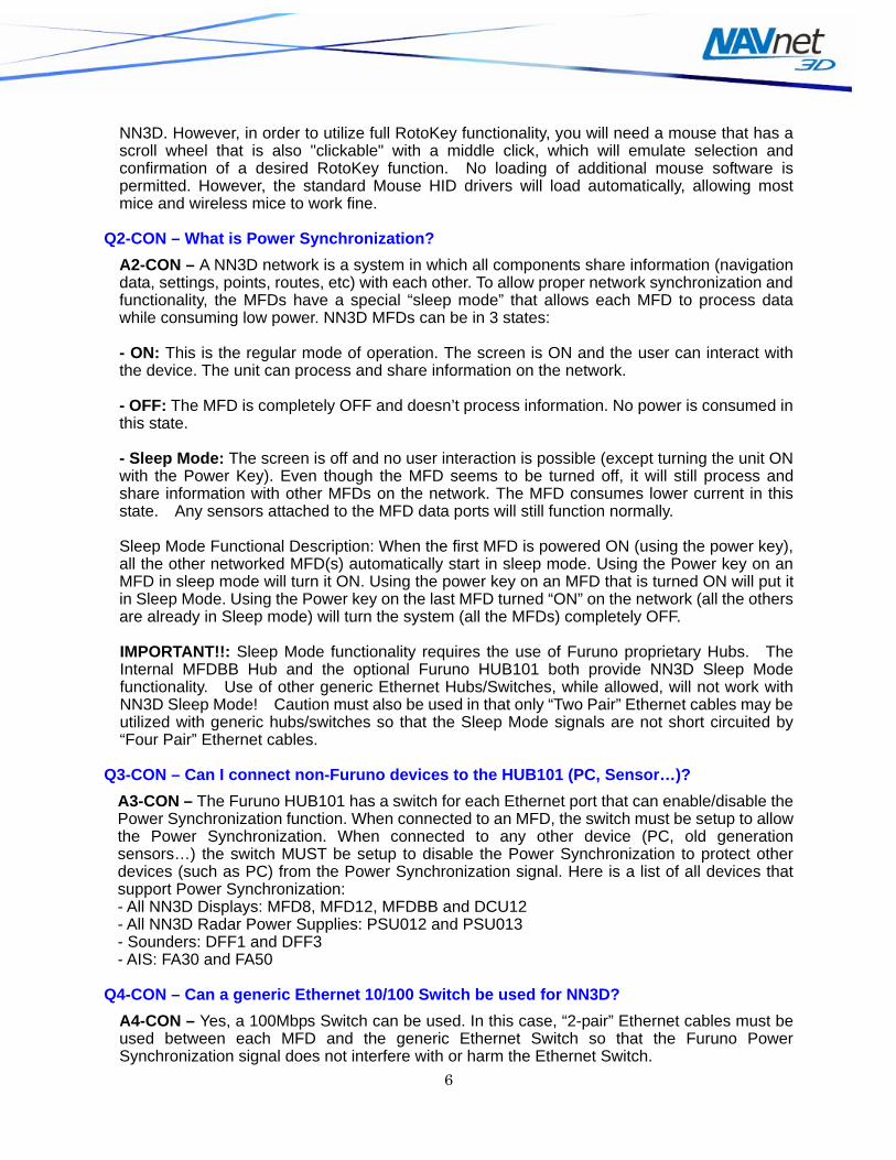
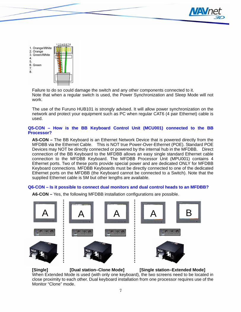
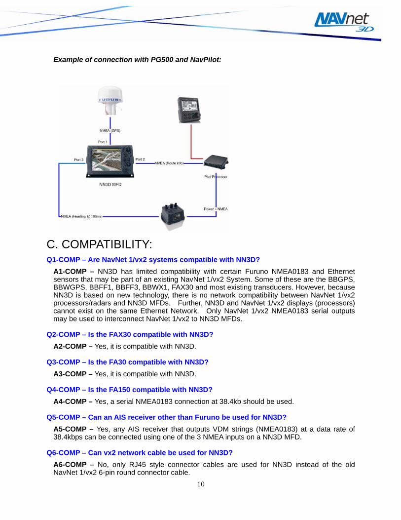
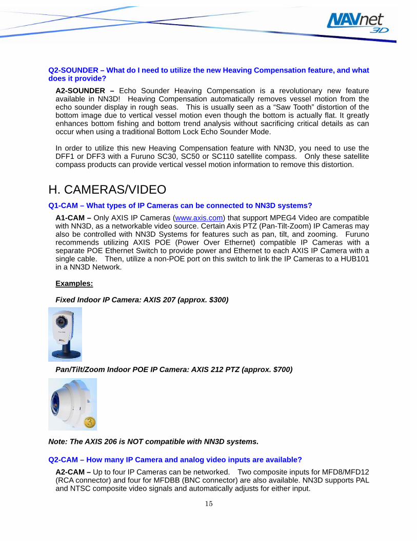