Embed Size (px)
Citation preview

SANDIA REPORTSAND2012-3840Unlimited ReleasePrinted May, 2012
Navigating An Evolutionary Fast Pathto Exascale – Expanded Version
R.F. Barrett, S.D. Hammond, C.T. Vaughan, D.W. Doerfler, M.A. Heroux
Center for Computing ResearchSandia National LaboratoriesAlbuquerque, NM 87185email: rfbarre,sdhammo,ctvaugh,dwdoerf,[email protected]
J.P. Luitjens, NVIDIA Corporation, 2701 San Tomas Expressway Santa Clara, CA,95050 [email protected]
D. Roweth, Cray UK Ltd, 2 Brewery Court, High Street, Theale, Reading, RG75AH, United Kingdom, [email protected]
Prepared bySandia National LaboratoriesAlbuquerque, New Mexico 87185 and Livermore, California 94550
Sandia National Laboratories is a multi-program laboratory managed and operated by Sandia Corporation,a wholly owned subsidiary of Lockheed Martin Corporation, for the U.S. Department of Energy’sNational Nuclear Security Administration under contract DE-AC04-94AL85000.
Approved for public release; further dissemination unlimited.

Issued by Sandia National Laboratories, operated for the United States Department of Energyby Sandia Corporation.
NOTICE: This report was prepared as an account of work sponsored by an agency of the UnitedStates Government. Neither the United States Government, nor any agency thereof, nor anyof their employees, nor any of their contractors, subcontractors, or their employees, make anywarranty, express or implied, or assume any legal liability or responsibility for the accuracy,completeness, or usefulness of any information, apparatus, product, or process disclosed, or rep-resent that its use would not infringe privately owned rights. Reference herein to any specificcommercial product, process, or service by trade name, trademark, manufacturer, or otherwise,does not necessarily constitute or imply its endorsement, recommendation, or favoring by theUnited States Government, any agency thereof, or any of their contractors or subcontractors.The views and opinions expressed herein do not necessarily state or reflect those of the UnitedStates Government, any agency thereof, or any of their contractors.
Printed in the United States of America. This report has been reproduced directly from the bestavailable copy.
Available to DOE and DOE contractors fromU.S. Department of EnergyOffice of Scientific and Technical InformationP.O. Box 62Oak Ridge, TN 37831
Telephone: (865) 576-8401Facsimile: (865) 576-5728E-Mail: [email protected] ordering: http://www.osti.gov/bridge
Available to the public fromU.S. Department of CommerceNational Technical Information Service5285 Port Royal RdSpringfield, VA 22161
Telephone: (800) 553-6847Facsimile: (703) 605-6900E-Mail: [email protected] ordering: http://www.ntis.gov/help/ordermethods.asp?loc=7-4-0#online
DE
PA
RT
MENT OF EN
ER
GY
• • UN
IT
ED
STATES OFA
M
ER
IC
A
2

SAND2012-3840Unlimited ReleasePrinted May, 2012
Navigating An Evolutionary Fast Path to Exascale –Expanded Version
The computing community is in the midst of a disruptive architectural change. Theadvent of manycore and heterogeneous computing nodes forces us to reconsider every aspectof the system software and application stack. To address this challenge there is a broadspectrum of approaches, which we roughly classify as either revolutionary or evolutionary.With the former, the entire code base is re-written, perhaps using a new programminglanguage or execution model. The latter, which is the focus of this work, seeks a piecewisepath of effective incremental change. The end effect of our approach will be revolutionaryin that the control structure of the application will be markedly different in order to utilizesingle-instruction multiple-data/thread (SIMD/SIMT), manycore and heterogeneous nodes,but the physics code fragments will be remarkably similar.
Our approach is guided by a set of mission driven applications and their proxies, focusedon balancing performance potential with the realities of existing application code bases.Although the specifics of this process have not yet converged, we find that there are severalimportant steps that developers of scientific and engineering application programs can taketo prepare for making effective use of these challenging platforms. Aiding an evolutionaryapproach is the recognition that the performance potential of the architectures is, in ameaningful sense, an extension of existing capabilities: vectorization, threading, and a re-visiting of node interconnect capabilities. Therefore, as architectures, programming models,and programming mechanisms continue to evolve, the preparations described herein willprovide significant performance benefits on existing and emerging architectures.
3

Acknowledgment
The breadth of our work has required special efforts from a variety of entities and staffwithin the Department of Energy and our industrial collaborators. The test beds used forthis research are funded by the Department of Energy’s NNSA ASC program and the Officeof Science Advanced Scientific Computing Research (ASCR) program. We acknowledge sup-port from AMD Inc, Cray Inc and NVIDIA for providing detailed information on hardwareplatforms and information relating to optimization opportunities.
Ted Barragy of AMD Inc, and John Levesque and Jeff Larkin of Cray Inc, providedinvaluable information and suggestions.
The CapViz team and others at Sandia provided the special skills and attention requiredto maintain and support the testbed systems used in this work.
4

Contents
1 Introduction 9
1.1 Related work . . . . . . . . . . . . . . . . . . . . . . . . . . . . . . . . . . . . . . . . . . . . . . . . . . . . . 11
2 Programming Models and Environments 13
3 Methodology 15
4 Case Study: Initial Porting of Mantevo Mini-Applications to Future Com-puting Architectures 17
4.1 Processor Core Performance . . . . . . . . . . . . . . . . . . . . . . . . . . . . . . . . . . . . . . . . 17
4.2 Intra-node performance . . . . . . . . . . . . . . . . . . . . . . . . . . . . . . . . . . . . . . . . . . . . 19
4.2.1 Finite difference stencils . . . . . . . . . . . . . . . . . . . . . . . . . . . . . . . . . . . . . . 20
4.2.2 MiniFE on a GPU . . . . . . . . . . . . . . . . . . . . . . . . . . . . . . . . . . . . . . . . . . 21
4.2.3 The Impact of Memory Speeds . . . . . . . . . . . . . . . . . . . . . . . . . . . . . . . . 23
4.3 Inter-node performance . . . . . . . . . . . . . . . . . . . . . . . . . . . . . . . . . . . . . . . . . . . . 24
4.3.1 On the XK6 . . . . . . . . . . . . . . . . . . . . . . . . . . . . . . . . . . . . . . . . . . . . . . . 25
4.3.2 Mapping processes to processors . . . . . . . . . . . . . . . . . . . . . . . . . . . . . . . 26
4.3.3 Alternative communication strategies . . . . . . . . . . . . . . . . . . . . . . . . . . . 29
5 Conclusions and Future Work 33
References 34
5

Appendix
A Programming Environment 39
A.1 Cielo . . . . . . . . . . . . . . . . . . . . . . . . . . . . . . . . . . . . . . . . . . . . . . . . . . . . . . . . . . . 39
A.2 Curie . . . . . . . . . . . . . . . . . . . . . . . . . . . . . . . . . . . . . . . . . . . . . . . . . . . . . . . . . . . 39
A.3 GPU . . . . . . . . . . . . . . . . . . . . . . . . . . . . . . . . . . . . . . . . . . . . . . . . . . . . . . . . . . . 40
A.4 Teller . . . . . . . . . . . . . . . . . . . . . . . . . . . . . . . . . . . . . . . . . . . . . . . . . . . . . . . . . . . 40
A.5 Dual-Socket, Oct-core AMD 2.4GHz Magny-Cours 6136 . . . . . . . . . . . . . . . . . . 40
A.6 Dual-Socket, Quad-core Intel 2.93GHz Nehalem 5570 . . . . . . . . . . . . . . . . . . . . 40
B MiniMD code examples 41
C MiniGhost code examples 45
D NVIDIA miniFE Study 49
D.1 Introduction . . . . . . . . . . . . . . . . . . . . . . . . . . . . . . . . . . . . . . . . . . . . . . . . . . . . . 49
E Characterizing the Sensitivity of Charon and MiniFE to Variation in DDRInterface Frequency on Workstation-Class Multicore Processor Architec-tures 53
E.1 Introduction . . . . . . . . . . . . . . . . . . . . . . . . . . . . . . . . . . . . . . . . . . . . . . . . . . . . . 53
E.2 Test Beds and Method . . . . . . . . . . . . . . . . . . . . . . . . . . . . . . . . . . . . . . . . . . . . . 53
E.3 Results . . . . . . . . . . . . . . . . . . . . . . . . . . . . . . . . . . . . . . . . . . . . . . . . . . . . . . . . . 54
E.4 Summary and Conclusions . . . . . . . . . . . . . . . . . . . . . . . . . . . . . . . . . . . . . . . . . . 55
F Remapping the parallel processes in CTH 61
G More on Cielo 63
6

List of Figures
3.1 Steps in an Evolutionary Path to Exascale Readiness . . . . . . . . . . . . . . . . . . . . 15
4.1 Performance of varying miniGhost problems on an XK6 node . . . . . . . . . . . . . 20
4.2 Speedup of miniFE CUDA Implementation (NVIDIA Fermi M2090 vs. Hex-Core 2.7GHz E5-2680 . . . . . . . . . . . . . . . . . . . . . . . . . . . . . . . . . . . . . . . . . . . . . . 21
4.3 Strong and Weak Scaling of MiniGhost on XK6 . . . . . . . . . . . . . . . . . . . . . . . . 26
4.4 Cielo process map . . . . . . . . . . . . . . . . . . . . . . . . . . . . . . . . . . . . . . . . . . . . . . . . . 27
4.5 Performance of MiniGhost with MPI-rank remapping on Cielo . . . . . . . . . . . . 29
4.6 CTH boundary exchange and computation . . . . . . . . . . . . . . . . . . . . . . . . . . . . 30
4.7 Performance of miniGhost Communication Strategies on Cielo . . . . . . . . . . . . 31
D.1 Speedup of miniFE CUDA Implementation (NVIDIA Fermi M2090 vs. Hex-Core 2.7GHz E5-2680 . . . . . . . . . . . . . . . . . . . . . . . . . . . . . . . . . . . . . . . . . . . . . . 51
E.1 Memory Bandwidth: miniFE Finite Element Mini-Application . . . . . . . . . . . . 57
E.2 Memory Bandwidth: Charon Device Simulation Application . . . . . . . . . . . . . . 58
E.3 Memory Bandwidth: miniFE compared to Charon . . . . . . . . . . . . . . . . . . . . . . 59
F.1 Performance of CTH with MPI-rank remapping on Cielo. . . . . . . . . . . . . . . . . 62
G.1 Cielo XE6 architecture. Image courtesy of Cray Inc. . . . . . . . . . . . . . . . . . . . . . 63
G.2 The XE6 compute node architecture. Images courtesy of Cray, Inc. . . . . . . . . 64
G.3 The XE6 Gemini architecture. Images courtesy of Cray, Inc. . . . . . . . . . . . . . . 65
7

List of Tables
4.1 Speedup of manual vectorization for miniMD force calculation and full appli-cation runtime. . . . . . . . . . . . . . . . . . . . . . . . . . . . . . . . . . . . . . . . . . . . . . . . . . . . 18
4.2 Relative Runtime Slowdown of miniFE and Charon from Reduced MemoryFrequency (Relative to Memory Frequency of 1333MHz, Lower is Worse) . . . . 24
4.3 miniGhost average hop counts on Cielo . . . . . . . . . . . . . . . . . . . . . . . . . . . . . . . 28
E.1 Test Bed Descriptions . . . . . . . . . . . . . . . . . . . . . . . . . . . . . . . . . . . . . . . . . . . . . 54
8

Chapter 1
Introduction
High Performance Computing (HPC) architectures of the coming decade will be significantlydifferent in structure and design than today. We have already seen clock rates and nodecounts stabilize, and core counts increase. Now emerging are increased vector lengths, greaterlevels of hardware-enabled concurrency and new memory architectures that are stronglynon-uniform and may soon lose cache coherency. Adoption of new, potentially immature,technologies presents many challenges including hardware reliability, scalability and, in thecase of many proposed technologies, programmability and performance portability. Sinceproposed designs represent a radical departure from existing petascale technologies, newresearch projects have started in order to identify and develop solutions for many of theseproblems. One of the greatest concerns facing programs such as the Advanced Simulationand Computing (ASC) initiative in the United States is how best to port full applications thathave been developed over nearly two decades. These applications are considerable in size,with many comprising of millions of lines of source implemented in a variety of programminglanguages (some of which use non-standard features) and utilize tens of supporting libraries.ASC in particular, many of these applications codify significant bodies of knowledge whichhave developed over multiple generations of scientists. Alongside the demands of portingsuch large codes are the continued requirements associated with on-going programmatic-level work. Put simply, science discovery cannot stop while applications and algorithms arerewritten for future systems and re-validated to ensure correct scientific output.
In this context, many in the HPC industry question how full science applications will beported to new architectures. On one side of the debate is a view that significant applicationrewrites will be required in order to obtain the full potential performance of new hardware.On the other side is a view, described above, that the pedigree of existing code and thecomplex science which it embodies must be gradually evolved and augmented over time fornew platforms so that scientific delivery can continue and the cost associated with porting isreduced or at least amortized. We regard these views as the revolutionary and evolutionaryapproaches to Exascale, respectively.
The work reported in this paper (and in expanded version in [5]) describes an initialseries of experiments performed in the evolutionary context. We note that studies usingrevolutionary approaches are also underway and will be reported in future publications. Ourwork focuses on three levels of porting which we expect to be commonplace choices for themodification of codes on future platforms: (i) optimization within the processor core, typi-
9

cally investigating the improvement of vector-level parallelism and the modification of codeto exploit near memory subsystems; (ii) optimization of code for the compute node as awhole using techniques such as thread-level parallelism, introduction of compiler directivesto drive compute offloading, data motion reduction and adaptation for node-level topolo-gies such as non-uniform memory architecture (NUMA) domains, and, (iii), optimizationof inter-node communication to improve message pipelining or to utilize novel features inadvanced network interconnects.
The specific contributions of this work are:
• Documented porting and analysis of several key Sandia mini-applications (miniapps)running on advanced computing architectures. The use of miniapps from the Mantevosuite enables us to draw conclusions that are relevant to production codes used bythe National Nuclear Security Agency (NNSA) and ASC programs. We employ noveltechnologies to aid in this porting including traditional OpenMP pragmas as well asintroduction of OpenACC directives to enable execution on GPUs, and intrinsic func-tions to improve levels of compiler vectorization;
• Benchmarking the effects on runtime of changes in hardware and environment con-figuration, in particular changes in memory bandwidth, MPI-rank placement and thevarying use of threads/MPI ranks to use available processor resources. Such studies en-able us to investigate the opportunity for optimizations outside of traditional changesin source code and reflects our on-going view that optimization of runtime encompassesa wide range of options including software configuration as well as design. We notethat such options can have significant impact at scale and demonstrate the effect ofsuch options for runs of over 16,000 processor cores;
• Highlighting of several architectural parameters which serve as bottlenecks or limits tofurther improvements in performance. A natural effect of early generations of hardwareis that a number of optimization opportunities is likely to still be present in the design.In our work we use miniapps to identify these and discuss how, when addressed, thesemay provide improvement in runtime performance.
Due to the various, non-uniform levels of maturity of the systems used for this work we do notprovide direct hardware-to-hardware comparison, instead preferring to use relative measuresof improvement for each experiment. As the hardware and software stacks associated withplatform develop further we will intend to provide future publications which will enabledirect performance comparisons to be made.
10

1.1 Related work
The number and breadth of challenges associated with preparing for multi-petascale andexascale-class computing are significant and have helped to create a rich set of academicinvestigations touching on comparison of computer architectures [19, 2], optimization forspecific classes of hardware [13, 8] and programming languages and mechanisms [25, 21, 16, 1].
11

12

Chapter 2
Programming Models andEnvironments
Programming models (abstractions used to reason about program design and implemen-tation) and programming environments (compilers and tools used to implement software,correlated in design to one or more programming models) are some of the most challengingand dynamic elements on the path to exascale computing. Single program multiple data(SPMD) built on top of MPI has by far been the dominant programming model and envi-ronment pair since the ermergence of distributed memory computing two decades ago. Thereis overwhelming evidence that single-level SPMD (statically assigning a process per core) isinsufficient to achieve optimal performance. Even more importantly, this approach will notscale with the performance potential of future systems. If we are going to continue trackingfuture performance trends, we need to augment or replace existing strategies.
Revolutionary approaches in this area arguably include Chapel [14], ParalleX [16] andSwarm [1], since these languages or execution models, or both, would require a completeredesign of an existing application. Although future systems may demand such efforts, mostapplication teams are using a more evolutionary approach, sometimes called MPI+X, bycombining SPMD (via MPI) with one or more node-level programming environments suchas OpenMP [12], Intel Threading Building Blocks (TBB) [23], CUDA [22] or C++11 threads.
Although MPI+X may appear incremental, it is in fact very challenging to implement.In order to successfully scale on current and future heterogeneous and manycore nodes,the computational kernels of an existing (MPI) application must be redesigned to supportdynamic partitioning and scheduling of work by the node-level runtime system. Typically thisis most easily done by encapsulating kernels in stateless functions that can be parametrizedto dynamically execute some runtime-selected portion of work such that, when scheduled toa processing element, the computation is performed efficiently. All node-level programmingmodels and environments are compatible with this approach and some, such as TBB andCUDA, explicitly require it.
Interestingly, by going through the above refactoring processing, we not only makeMPI+X work well, but we position ourselves well for any future programming and exe-cution model. The effort of exposing and encapsulting parallelizable computations in thismanner is intrinsically valuable. Furthermore, by optimizing node-level performance forruntime systems such as CUDA, we also move in the direction of hiding latency via task
13

concurrency. Optimizing occupancy rates in CUDA is a harbinger of the kind of reasoningneeded for efficient use of ParalleX and Swarm.
14

Chapter 3
Methodology
ExistingCode
TuningCore &Cache
Port toOpenMP/OpenACC
Tune for
Node
Tunefor Inter-
Node
Exis
ting
Cod
e /
Toda
y
Exas
cale
Rea
dine
ss
Vectorization Threading Multiple-Socket /Thread Optimizaton MPI
Figure 3.1. Steps in an Evolutionary Path to ExascaleReadiness
In this paper we document our experiences with attempting an evolutionary migration ofcode from existing petascale machines to exascale-class prototype hardware. The focus istherefore on maintaining as many of the existing investments in code as can be productivelyretained and, where possible, adapting the structure for new classes of hardware. Towardsthis end have empirically found our code modifications follow a largely similar path regardlessof the hardware technology being employed. Figure 3.1 represents our migration strategythat starts with our existing code and proceeds through a series of steps to port and optimizethis for future systems. In practice some of these steps may occur in parallel or out of theorder described. The principle steps of our porting have so far been the following:
1. Vectorization
2. Threading
3. Tuning for the Compute Node and
4. MPI/Inter-Node Parallelism
The stages of this process capture our intent to introduce improved levels of parallelism intoour code which will be essential for application performance in the coming decade. Whilstthe specifics of how this parallelism is presented to the compiler or the machine are unique toeach hardware platform, the locating of parallelism is primarily a property of the algorithm
15

being used. Our experience is that the knowledge of parallelism obtained through this processcan therefore be re-used between different compute architectures and programming modelsreducing the time and cost associated with porting.
16

Chapter 4
Case Study: Initial Porting ofMantevo Mini-Applications to FutureComputing Architectures
In this last section of the paper we describe a series of short case studies which describe thevalue of mini-applications in assessing the capabilities and characteristics of future computingarchitectures and programming models. In so doing we are able to survey state of the artprototype computing architectures and provide initial commentary on how applications maybe mapped to them using evolutionary modifications to the application. In order to separatethe various levels of tuning being conducted, our results are split into three sections: (1)optimization within the processor core; (2) optimization within a whole compute node and,(3), optimization between compute nodes.
In this section we use the term core, processor, and node in a flexible context since preciseterminology is still being refined throughout the community. For purposes herein, we viewa core as being as a unit which is capable of performing calculation including traditionalprocessor cores or lightweight cores as found in new hardware types such as a GPU; we viewa processor as essentially being a socket and a node is a network endpoint.
4.1 Processor Core Performance
Future computing hardware is expected to provide increased parallelism in the processor corethrough the availability of, and increased width of, vector registers which are able to performa single instruction over multiple pieces of data simultaneously. With the introduction ofMMX instructions by Intel in 1995 and subsequent additions in the form of SSE and latterlyAVX, many of the available floating-point operations in commodity processors require codesto exploit high levels of data parallelism in order to achieve a high proportion of peak chipperformance. A well tuned compiler can very often detect opportunities for vectorizationproviding the code is structured in a manner that the compiler can safely determine theintroduction of vectored instructions will not violate the original statement ordering. Wherecode control is complex or inter-statement dependencies exist, compilers are often unable togenerate vectorized code resulting in slower execution. One potential approach to addressing
17

Table 4.1. Speedup of manual vectorization for miniMDforce calculation and full application runtime.
Force Total(Speedup (x)) (Speedup (x))
AMD A8 3850 APU, 2.90GHz, SSE4aSingle Precision 1.26 1.21Double Precision 1.56 1.49Intel Westmere 5690, 3.47GHz, SSE4.2Single Precision 1.57 1.43Double Precision 1.42 1.33Intel SandyBridge, 2.60GHz, SSE4.2Double Precision 1.85 1.60
this issue is for the programmer to employ manual vectorization through the introductionof intrinsic operations – a library of routines which communicate how the developer wouldlike vectorization to occur. Such code constructs allow developers to easily express low-levelvector parameters and data operations that either expand directly to assembly instructionsor provide programmer intent to the compiler allowing it to manipulate these statements intovectorized operations. Typically not for the faint of heart, we apply this approach herein inorder to illustrate the potential performance advantages with a view that maturing compilertechnology may provide additional opportunities for vectorization in the future and that theperformance identified helps us to assess what the hardware may in fact be capable of.
Our initial inspections into poorer than expected performance of miniMD on commodityprocessors has shown that the force compute loop (which is responsible for up to 90% ofserial runtime) cannot be vectorized due to the complex pointer behavior being employedas well as sparse operand loads from memory. The use of double pointer indirection to mapdata structures into the compute kernel prevents the compiler from determining whethervector instructions can be utilized without violating ordering constraints despite a validvectorization being possible from an algorithmic perspective.
The force function computes the interaction forces between each pair of atoms thatexist in a specific neighbor list. Due to the sparse nature of the atom information and thecondition operations associated with identifying whether the atom pair is within a cut-offzone, vectorization of this code is particularly challenging. However, the high proportion ofexecution associated with the function makes this a candidate for optimization. In orderto address the poor level of vectorization the main force compute loop was instrumentedwith vector intrinsic operations enabling the compiler to generate code with increased levelsof vectorization. Table 4.1 shows the speedup obtained through the use of SSE4 intrinsicoperations on several processors. Despite the SandyBridge being capable of executing AVXinstructions, we have provided results from our SSE ports to enable a comparison.
SSE provides a 128-bit wide vector unit (four single-precision operands or two double-precision operands) enabling a maximum speedup of floating point calculations equivalent
18

to the vector width. Although each operation within the force kernel is vectorized using anintrinsic operation, the speedup obtained is lower than the theoretical maximum as someinstructions over vector registers are serialized within the processor core and other architec-tural bottlenecks such as memory operations are not executed in parallel. The output of thevector intrinsic instrumented codes is not identical to non-vectored source as the operationsmay lead to a change in rounding effects, but has been thoroughly tested to ensure theresults are acceptable to domain scientists. Our experience of rounding has shown that theintroduction of intrinsics can yield subtle changes in output and even execution behaviorand therefore careful design and post-implementation testing are required.
As we look forward the coming arrival of the Intel MIC architecture with an increasedvector width, we predict that the addition of intrinsics to key application kernels may be-come more commonplace. We further expect the structure of the refactored intrinsic forcekernel to be reusable on MIC platforms moving forward with only minor changes to adaptto the wide vector registers. Within the evolutionary context, adaption of key kernels usingintrinsics therefore allows us to migrate applications to new platforms and provide signifi-cant improvement in execution speed with changes isolated to only short sections of code.Although intrinsics are not available for the GPU in the same sense, the knowledge of al-gorithm parallelism is fundamental to informing us of future ports to such architectures.Furthermore, many of the improvements being prepared for future exascale-class platformscan be reused on a number of our existing systems.
4.2 Intra-node performance
Effectively exploiting the performance potential provided by increasingly complex node ar-chitectures is currently seen as one of the major challenges for on-going code development.In this section we provide three examples illustrating several issues that the application de-veloper may need to consider on an increasingly complex compute node. Specifically wefocus on : (1) the porting of miniGhost to NVIDIA GPUs using the recently announcedOpenACC compiler directive toolkit, demonstrating initial identification of parallelism inthe algorithm and the performance obtained from OpenACC; (2) the porting of the miniFEFinite Element assembly phase to NVIDIA GPUs using CUDA which identifies the high levelof register spilling present in the code and discusses how this will be addressed in future GPUsystems and, finally, (3) a study of miniFE assembly and solve phase sensitivity to changesin memory bandwidth. The issues raised in these small studies demonstrate the value ofmini-applications in identifying potential performance bottlenecks or sensitivities. The in-formation being obtained through this work is able to drive analysis of larger applications aswell as hardware and can have real impact in informing our hardware selection choices andsubsequent optimization activities.
19

0
0.5
1
1.5
2
128x128x128
128x128x256
128x256x256
256x256x256
256x256x512
256x512x512
512x512x512
512x512x1024
512x1024x1024
Speedup o
ver
MP
I
Mini-Ghost Problem Size
MPI+OpenMP (4 Ranks x 4 Threads)MPI (16 Ranks)
OpenACC
Figure 4.1. Performance of varying miniGhost problemson an XK6 node
4.2.1 Finite difference stencils
Computation in MiniGhost is based on a triply nested loop, whereby each point in thedomain is updated as a function of the average over adjacent points. The simplicity of thiscomputation and the ability to easily configure varying levels of compute complexity let usexpose and explore numerous issues expected to significantly impact the performance of fullapplications that employ difference stencils and the halo exchange.
The hybrid MPI + OpenMP version began with a straightforward wrapping of the outer-most loop the !$OMP PARALLEL DO directive. It was also then a straightforward port toOpenACC, replacing this directive with the !$acc parallel loop directive. However, ona node with a memory hierarchy, such as that on a dual-socket node, the memory affinityis different: with OpenMP, the arrays should be physically distributed across the memoryhierarchy of the processing cores (via first-touch) while with a hybrid off-load system, theentire array should be resident on a single processor’s memory so that the movement to thedevice is straightforward. The MPI-everywhere version automatically maintains processorcore and memory affinity.
The stencil loop required no additional use of OpenMP directives. The OpenACC versionenabled the means for effectively mapping the data onto the GPU, required to achieveacceptable performance. The Fermi processor is organized into 16 groups of 32 cores, so adirective is used to map the computation as x− y slices of GRID to 16 blocks (num gangs),mapping them each as vectors (vector length) of length 32 onto the 32 core warps.
20

0
1
2
3
4
5
6
10 20 30 40 50 60 70 80 90 100 110 120 130 140 150
Sp
ee
du
p o
ve
r C
PU
(x)
N
Matrix AssemblyMatrix Generation
CG SolveOverall
Figure 4.2. Speedup of miniFE CUDA Implementation(NVIDIA Fermi M2090 vs. Hex-Core 2.7GHz E5-2680
Single node performance on Curie of the MPI-everywhere, MPI+OpenMP, and MPI+OpenACCimplementations, illustrated in Figure 4.1, shows that the GPU gives a speedup over the MPI-everywhere ranging from around 25% to 80% as the amount of work increases. However, ifthe data to be operated on must be moved to and from the GPU, the advantage reverses. Thebest MPI+OpenMP configuration of 4 MPI ranks per node each with 4 OpenMP threadsoutperforms the MPI version by about 10%, but this quickly reverses as the problem sizeincreases, with performance decreasing to 80% of the MPI version. It is beyond the scopeof this paper examine this more closely, though its likely that this is an artifact of the firstgeneration Interlagos node architecture and thus its reasonable to expect that it will beaddressed in the next generation Trinity node.
Direct comparison of performance between the host and device is problematic since mem-ory sizes differ significantly, a situation common to their sorts of architectures. On Curie,the GPU device has significantly less memory that that available to the host (6 GBytes vs.32 GBytes), and therefore the node can execute the larger problem shown on the graphwhile the GPU cannot. From an application perspective, the ultimate comparison then ismulti-node strong scaling, examined in Section 4.3.1.
4.2.2 MiniFE on a GPU
MiniFE consists of three principle phases: generation of the matrix structure, assembly ofthe finite-element matrix, and the solution of the sparse linear system using the ConjugateGradient method. Here we focus on key performance limiters in porting the matrix assemblyphase of the algorithm to an NVIDIA GPU. using the CUDA programming model.
21

The assembly phase involves computing the element operators for each element and thensumming the operators into a final matrix. We parallelize this phase by having threadsoperate on separate elements with the computation of the element operator and the summa-tion into the linear system performed within a single kernel. Although the computation ofthe element operators is embarrassingly parallel, the summing into a linear system requiressynchronization to avoid data race conditions. The use of a single kernel is preferred in thisinstance because it avoids having to store the state for the element operator and then havingto later re-read that state during summing into the linear system.
By using one thread per element we were able to leverage the original code for theconstruction of the element operator subject to additions for compilation to a CUDA kerneland a modification of the code to use the ELL sparse-matrix representation [7] of the originalcompressed-row (CSR) form. Atomic addition operations are employed in the kernel toprevent race conditions in updating the global matrix.
The computation of the element operator involves a number of floating-point heavy op-erations including computing the matrix determinant and the Jacobian. The large numberof floating point operations suggest that the performance should be FLOP limited but anal-ysis using NVIDIA’s compute profiler has shown that the performance is in fact bandwidthbound due to register spilling.
The cause of this register spilling can be identified as the element operator which requiresa large thread state, including 32 bytes for node-IDs, 96 bytes for node coordinates, 512 bytesfor the diffusion matrix, 64 bytes for the source vector as well as data to store the Jacobianand matrix determinant. The Fermi GPU architecture supports up to 63 32-byte registers perthread limiting the total register storage to 252 bytes. As a result of this limit, any additionalstate must be spilled to at least L1 cache and potentially further to L2 or memory. Since theL1 cache can be up to 48kB in size but is shared by 512 threads this can result in as little as96 bytes of L1 cache storage per thread. In addition, the L2 cache is 768kB shared by 8192threads, again leaving only 96 bytes of storage per thread. Since L1 and L2 are insufficientlysized to store the required operator state, registers are spilled to global memory causing thecomputation to become bandwidth bound.
One method to improve the performance of bandwidth bound kernels is to increase theoccupancy. However, in this case, the kernel’s occupancy is limited by register usage. Sincethe register usage is higher than is available in hardware it is not possible to increase thisoccupancy without further increasing register spilling.
We tuned the kernel to reduce register usage, including algorithmic changes that exploit-ing symmetry in the diffusion operator and reordering computations so that data is loadedimmediately prior to being used. We have also applied several traditional optimization tech-niques including pointer restriction, inlining of functions, and unrolling of loops. Finally,we also position a portion of the state in shared memory and experimented with L1 cachesizes. The best performance is achieved by placing the source vector into shared memoryand enabling a larger L1 cache. Whilst these optimization greatly reduce register spilling,512 bytes of state is still spilled per thread. To ensure fair comparison, all optimizations
22

that were applicable to the original CPU code were back ported also improving the CPUperformance.
The performance of the CUDA version of miniFE was compared to the MPI-parallelversion of miniFE running on a Tesla M2090 and a hex-core Intel Xeon 2.7GHz E5-2680.We tested for various problem sizes of N3 hexahedral elements. The speedup for each of thethree phases of the algorithm is reported in Figure 4.2.
The assembly realizes a 4x speedup and the solve phase is 3x faster. The generation ofthe matrix structure exhibits a slowdown because it is computed on the host in CSR format,transferred to the device, and then converted to ELL format. Whilst possible to move thiscomputation to the device, the low proportion of time consumed by these operations doesnot dominate performance.
Future generations of NVIDIA systems are expected to address some of the findings fromthis study, including an increased number of registers per thread and increases in the size ofL1 and L2 memories. Improvements in the CUDA compiler may also lead to a reduction inthe number of register spills or the impact that register spills will have on execution time.
4.2.3 The Impact of Memory Speeds
It is widely accepted that the performance of the memory sub-systems used in future exascalecomputers will improve substantially. This is driven by a realization that application per-formance, even on contemporary systems, is frequently limited by the “memory wall” [20].If compute devices experience rapid improvements in calculation throughput, memory willneed to be improved significantly if applications are not to become entirely throttled onmemory access. However, the question of whether the improvement in memory performancewill exceed or even match that of compute hardware is still unanswered. Therefore, there isa very real risk that applications will need to execute using lower memory bandwidth in thefuture.
In this section we describe a study in which we alter the clock rate of memory compo-nents in a system through BIOS control, effectively slowing the rate at which memory canprocess requests. This enables an analysis of code performance where there is a growingdivergence between compute throughput and that of memory (which may be the effect ofsignificant improvement in compute hardware that is unmatched by equivalent improvementin memory subsystems). Table 4.2 presents the relative effect on sections of miniFE andCharon (the parent application to miniFE) runtime as the clock rate of memory is loweredfrom 1333MHz to 1066MHz and 800MHz. The processor used for this study is a dual-socketoct-core AMD Interlagos running at 2.9GHz. The assembly time in miniFE and the Jacobiangeneration of Charon is unaffected by the change indicating that these sections of code arenot predominantly memory bound, whilst the runtime of the conjugate-gradient (CG) solverincreases by approximately 16% in the 800MHz case. Of interest is that miniFE is able toclosely track equivalent changes in its parent code for the solve phase (which in both codes
23

Table 4.2. Relative Runtime Slowdown of miniFE andCharon from Reduced Memory Frequency (Relative to Mem-ory Frequency of 1333MHz, Lower is Worse)
800MHz 1066MHz 1333MHzminiFE Mini-ApplicationFinite Element Setup 0.996 1.000 1.000CG Solve 0.841 0.957 1.000Charon Device Simulation ApplicationPrec/Newt 0.960 0.980 1.000Jac/Newt 1.000 1.000 1.000Adv/Newt 0.920 0.970 1.000Solve/Newt 0.840 0.940 1.000
is the dominant contributor to runtime) giving us confidence in the relevant of our studiesusing mini-applications.
From this short study we can begin to assess the likely impact that a reduced per-corememory bandwidth may induce. A runtime increase of 16% is approximately half of the dropin memory bandwidth, indicating that miniFE and Charon are clearly highly sensitive tomemory bandwidth in their solve phases but that some of the bandwidth loss can be coveredeither through efficient use of the memory hierarchy or latency hiding by the processorthrough the use of prefetching and deep instruction pipelines.
4.3 Inter-node performance
Our goal of an evolutionary path includes the assumption that inter-node parallelism willcontinue, in the foreseeable future, to be implemented using functionality provided by MPI.(This does not rule out the use of MPI in a revolutionary approach.)
In this section we explore some issues associated with the ubiquitous nearest neighborcommunication pattern. Our work is informed by CTH, an explicit three dimensional multi-material shock hydrodynamics code [18]. CTH models high-speed hydrodynamic flow andthe dynamic deformation of solid materials, and solves the equations of mass, momentum,and energy in an Eulerian finite volume formulation. MiniGhost, shown to effectively repre-sent the inter-process communication requirements of CTH, provides a tractable means forexploring strategies for improving the performance characteristics of the full application.
We begin by examining miniGhost on Curie. Next, we address a performance issueassociated with process-to-processor mapping, noticeable only at large scales. Then weinvestigate an alternative to the very large message strategy implemented in CTH and manyother applications.
24

4.3.1 On the XK6
As seen above, Curie’s GPU provides a significant performance capability for the compu-tation of difference stencils, but the cost of moving data between the host and device on anode overwhelms the performance of the computation. To minimize this expense, all arraysare maintained on the device, and only the halo is transferred to and from the host for MPIhandling. The MPI+OpenACC implementation uses one MPI rank per node, a (current)limitation of the OpenACC implementation used here.
Problem sets were configured to mimic the profiles of CTH. Weak scaling experimentsdemonstrate the power of the GPU in comparison with all of the processor cores for theMPI and MPI+OpenMP implementations. Strong scaling experiments were configured todemonstrate the manner in which a domain scientist would use Curie’s capabilities, high-lighting the effects of maintaining the state on the GPU. Representative results are shownin Figure 4.3.
The weak scaling problem involves 16 variables on a 256× 256× 512 grid per node. Thisensures that the MPI and OpenMP processes on a host node have a reasonable amount ofwork (128×128×128 per rank or thread, resp.) while still allowing that work to fit onto theGPU device. Although the communication cost dominates the MPI+OpenACC runtime, thespeed of the computation allows it to maintain its advantage over MPI and MPI+OpenMP.However, the gap closes at higher node counts.
The strong scaling problem involves 20 variables operating on a 1024 × 1024 × 1024grid. Most notable is that due to the GPUs’ memory constraint relative to the host node,the OpenACC implementation requires a minimum of 32 nodes while the MPI implementa-tions can run on eight nodes. However, at that scale, the MPI+OpenACC implementationout-performs the MPI implementation by about 40%. The MPI+OpenMP implementationbecomes competitive with the MPI implementation at higher node counts, a trend we seefor the strong scaling results as well as in the largest core counts on Cielo, discussed in thefollowing sections.
The MPI and MPI+OpenMP implementations spent 10-20% and 5-10% of runtime, re-spectively, in communication, highlighting the computational issue for OpenMP. As seen inthe following sections MPI+OpenMP outperforms MPI-everywhere on Cielo at very highscales. Interprocess communication is the sum of the work required to move data betweenthe parallel processes, which includes the time spent packing and unpacking the messagebuffers as well as the time spent in MPI. For the OpenACC implementation, then, this in-cludes the time spent moving the message buffers and partial sums between the host anddevice, resulting in mid-90% proportion of runtime spent in communication. We optionallyaggregated the variable boundaries into a single array for host-device movement, but thisincreased the cost since the individual transfers could be partially hidden by the packingof the other buffers. This demonstrates that the data movement is impacted by the injectrate mores than by either latency or bandwidth: the PCIx host-device connection is able toinject the transfer and quickly return to packing the next buffer.
25

0
10
20
30
40
50
60
1 2 4 8 16 32 64
Ru
ntim
e (
Se
cs)
Nodes
MPI+OpenMP (4 MPI Ranks + 4 OpenMP Threads per Node)MPI (16 Ranks per Node)
MPI + OpenACC (1 MPI Rank + 1 GPU per Node)
(a) Weak scaling: 256x256x256 grid per node,16 variables
0
50
100
150
200
250
300
350
400
5 10 15 20 25 30 35 40 45 50
Ru
ntim
e (
Se
cs)
Nodes
MPI+OpenMP (4 MPI Ranks + 4 OpenMP Threads per Node)MPI (16 Ranks per Node)
MPI+OpenACC (1 MPI Rank + 1 GPU per Node)
(b) Strong scaling, 1024x1024x1024 grid, 20 variables
Figure 4.3. Strong and Weak Scaling of MiniGhost onXK6
Its important to note that OpenACC is a new specification, and supporting compilershave only recently appeared. Our hope is that compilers will improve over time since wefound this programming methodology to be rather easy to use.
4.3.2 Mapping processes to processors
CTH provides a typical example of a code team adapting to computing architectures: inorder to avoid message latencies and exploit global bandwidth, computation is performedacross as many variables as possible before an boundary exchange across those variables canbe consolidated in to a single message per neighbor. But in a recently completed broad-based study of Cielo capabilities [3], the nearest neighbor boundary exchange encountered
26

...
95 94 93 92 91 90
01234567891011
12131415161716
6
...Figure 4.4. Cielo process map
significant scaling degradation beyond 8,000 processor cores.
The problem was traced to the mapping of the parallel processes to the three dimensionaltorus topology, illustrated in Figure 4.4. Neighbors in the x direction required a maximumof one hop and in the y direction a maximum of two hops. But the number of hops acrossthe network (referred to as the Manhattan distance) was shown to increase significantly inthe z direction. This combined with the very large messages of a typical CTH problem set(e.g. for the “shaped charge” problem, 40 three dimensional state variable arrays generatedmessage lengths of almost 5 MBytes) resulted in poor scaling beginning at 8k processes, atrend that accelerated after 16k processes.
In response, we implemented a means by which the parallel processes could be logicallyre-mapped to take advantage of the physical locality induced by the communication require-ments. In the normal mode, CTH (and miniGhost) assigns blocks of the mesh to cores ina manner which ignores the connectivity of the cores in a node. On Cielo, as with otherCray X-series architectures, cores are numbered consecutively on a node, and this numberingcontinues on the next node. Blocks of the mesh are assigned to cores by traversing the blocksof the mesh in the x direction of the mesh starting at one corner of the mesh. Once thoseblocks are assigned, the next block assigned is the block one over in the y direction of themesh from the first block assigned. The mesh is again then traversed in the x direction andblocks are assigned to cores. This process is continued until there are no more blocks in they direction. The next block assigned is then the first block in the z direction from the firstblock assigned. The blocks of the mesh with this z value are then assigned as the first blockswere assigned. This process is then repeated until all blocks in the mesh have been assignedto cores in the machine.
27

Number of Regular Order ReorderedMPI ranks X Y Z X Y Z
16 0.0 0.0 0.0 0.0 0.0 0.032 0.0 0.0 0.0 0.0 0.0 0.064 0.0 0.0 0.3 0.0 0.3 0.0128 0.0 0.0 1.0 0.0 0.5 0.0256 0.0 0.0 1.0 0.0 0.5 0.3512 0.0 0.1 2.0 0.0 0.6 0.41024 0.0 0.3 2.1 0.2 1.0 0.72048 0.0 0.3 2.7 0.3 1.2 1.24096 0.0 0.3 3.7 0.3 1.2 1.28192 0.0 0.5 5.1 0.2 1.1 2.016384 0.0 0.5 4.9 0.2 1.1 2.232768 0.0 0.5 5.6 0.2 1.1 2.565536 0.0 1.1 10.2 0.2 1.6 2.8131072 0.0 1.1 10.1 0.2 1.6 3.1
Table 4.3. miniGhost average hop counts on Cielo
Our remapping algorithm assigns blocks of the mesh to the cores of the machine bygroups. On Cielo, a group of blocks consists of a 2× 2× 4 group of blocks. These blocks arethen assigned to nodes as above. The result is a slight increase in the average hop counts inthe x and y directions, but a significant decrease in the average hop count in the z direction.A comparison of the number of hops between the two approaches is shown in Table 4.3.
This remapping strategy results in a significant improvement in scaling performance,illustrated in in Figure 4.5(a). Figure 4.5(b) shows that this is attributable to controllingthe time spent sending data in the z direction. We include the time spent in the reductionsum across each grid variable (inserted after computation on each variable to add applicationrealism as well as a synchronization point), illustrating that this functionality is not thesource of the issue, scaling well regardless of the processor mapping. We do see indicationsof the issue at the highest processor counts, though it is less pronounced. This remappingwas incorporated into CTH, the results of which are described in Appendix F.
As discussed in the related work section above, we are exploring ways for incorporatingthese ideas into a more general interface. We are also exploring the use of MPI Datatype inhandling the non-contiguous (but patterned) face data.
28

18
20
22
24
26
28
30
32
34
36
38
16 64 256 1024 4096 16384 65536 262144
Ru
ntim
e (
Se
cs)
Processor Cores
MPI OnlyMPI + OpenMP (4 Threads)
Remapped MPI OnlyRemapped MPI + OpenMP (4 Threads)
MPI + OpenMP (16 Threads)
(a) Time to solution
0
1
2
3
4
5
6
7
1024 2048 4096 8192 16384 32768 65536 131072
Co
mm
Tim
e (
Se
cs)
Processor Cores
XYZ
ReduceReorder XReorder YReorder Z
Reorder Reduce
(b) Communication time per direction (MPI version)
Figure 4.5. Performance of MiniGhost with MPI-rankremapping on Cielo
4.3.3 Alternative communication strategies
Node interconnects are also evolving, driven by new node architectures as well as cost andenergy conservation goals, encouraging exploration of new approaches within the contextof application requirements. Interconnects are designed as a balance of global bandwidth(the ability of the interconnect to move data), inject bandwidth (the ability of the NIC toput data onto the interconnect), and injection rate (the ability of a node to place messagesonto the NIC). Global bandwidth typically incurs the highest costs, both in terms of moneyand power consumption, and therefore we are preparing for a proportional decrease in thatcapability.
MiniGhost includes an application-relevant infrastructure for exploring alternative bound-
29

Figure 4.6. CTH boundary exchange and computation
ary exchange configurations [6]. The first configuration mimics that of CTH, which we callBulk Synchronous Parallel with Message Aggregation (BSPMA), was used above, illustratedin Figure 4.6. The second, called Single Variable Aggregated Faces (SVAF) transmits dataas soon as computation on a variable is completed, and thus six messages are transmitted foreach variable (up to 40), one to each neighbor, each time step. (Looking at Figure 4.6, thiseliminates the inner END DO and DO I = 1, NUM VARS.) The two x− y faces are contiguousin memory, so each may be directly sent using a call to a single MPI function. The otherfour faces are aggregated into buffers, resulting in four messages to their neighbors. A thirdmode, called single variable, contiguous pieces, computational overlapping mode (SVCP),is designed for use on architectures that are strongly biased toward significantly increasedmessage injection rates and injection bandwidth, a trend we see developing but not yet tothe extent of supporting this configuration using MPI [25].
BSPMA and SVAF have been configured for MPI-everywhere as well as MPI+OpenMP.For the latter on Cielo and Curie, its best configuration is four MPI ranks on each node,each spawning four OpenMP threads. Note that this increases the size of each message incomparison with the MPI-everywhere version. Because of ghost cells, the message size intwo directions almost doubles and the message size in the third direction almost quadruples.This is because the number of cells in two of the three directions is doubled. The size of themessage is based the size of the face with ghost cells, so if the size of a face is x× y cells forthe MPI everywhere case, the size of the message is (x + 2) ∗ (y + 2). If the number of cells
30

in one of these directions (say y) is doubled, then the size of the message is (x+ 2)∗ (2y+ 2),which is not quite double the original size, but close. Similarly, if the number of cells in bothdirections are doubled, then the size of the message is almost quadrupled.
Performance of these implementations on Cielo are shown in Figure 4.7. Effective map-
18
20
22
24
26
28
30
32
34
36
38
16 64 256 1024 4096 16384 65536 262144
Ru
ntim
e (
Se
cs)
Processor Cores
BSPMARemapped BSPMA
SVAFRemapped SVAF
Figure 4.7. Performance of miniGhost CommunicationStrategies on Cielo
ping of processes to processors is again critical to achieving good scaling, and as the numberof processors increases, SVAF becomes the best strategy. This is of significant interest sinceit reduces demand on costly global bandwidth by a factor of N , where N is the number ofvariables aggregated (40 for the shaped charge problem.)
31

32

Chapter 5
Conclusions and Future Work
With the goal of enabling an effective piecewise evolutionary path to making effective useof Exascale computing architectures, we described our explorations of a breadth of issuesthroughout the codesign space. While faced with uncertain choices of programming models,mechanisms, and perhaps languages designed to run in an uncertain computing environment,we have demonstrated a variety of ways the application developer can begin to concretelyand effectively prepare for an unknown specific machine but a widely accepted architecturalapproach. Although this work is presented in terms of processor, node, and inter-nodestrategies, we also see that a system-wide design is required to achieve overall reductionsin runtime. The common theme is, not unexpectedly, the organization of our data andthe way it is moved around and presented to the various components of the architecture.Most reassuring in terms of modifications to large code bases, we have demonstrated anevolutionary path that can also significantly improve performance on current and emergingarchitectures. Additional information in support of this paper is presented in [5], and deeperstudies on some of the topics herein will be presented in papers in preparation.
Our use of miniapps significantly improves our ability to rapidly explore ideas, and theseminiapps have been demonstrated to be predictive of full application codes with regardto some key performance issues [4], guiding our focus here. For example, the remappingstrategy has proven beneficial to CTH. That said, we reiterate that the output of a miniapp isinformation that must be interpreted within the context of the full application, and thereforethe application developer must apply and probably extend the experiences described in thispaper.
We are also studying revolutionary options, including less commonly used and new lan-guages (e.g. [21, 26, 10, 11]). It is also possible that a completely new architecture couldemerge from the exascale initiatives. Regardless, it appears that the fundamental conceptsfor exploiting these architectures will remain: presenting data to the compute engine in amanner that allows it to operate on the data in a vectorized multi-threaded fashion, sharingthat data with the parallel processes in efficient ways and exposing sufficient parallelism toeffectively hide ever-increasing relative latencies. The lesson learned from our incrementalevolutionary approach will not only help applications in the near to medium term, but alsoset the stage for a smoother transition to revolutionary environments.
33

34

References
[1] D.A. Bader, V. Kanade, and K. Madduri. SWARM: A Parallel Programming Frame-work for Multi-Core Processors. In First Workshop on Multithreaded Architectures andApplications (MTAPP), March 2007.
[2] K.J. Barker, K. Davis, A. Hoisie, D.J. Kerbyson, M. Lang, S. Pakin, and J.C. Sancho.Entering the Petaflop Era: the Architecture and Performance of Roadrunner. In Pro-ceedings of the 2008 ACM/IEEE Conference on Supercomputing, SC ’08, pages 1:1–1:11,Piscataway, NJ, USA, 2008. IEEE Press.
[3] B.W. Barrett et al. Report of Experiments and Evidence for ASC L2 Milestone4467 - Demonstration of a Legacy Application’s Path to Exascale. Technical ReportSAND2012-1750, Sandia National Laboratories, 2012.
[4] R.F. Barrett, P.S. Crozier, S.D. Hammond, M.A. Heroux, P.T. Lin, T.G. Trucano,and C. Vaughan. Assessing the Validity of the Role of Mini-Applications in PredictingKey Performance Characteristics of Scientific and Engineering Applications. TechnicalReport SAND2012-TBD, Sandia National Laboratories, 2012. In preparation.
[5] R.F. Barrett, S.D. Hammond, C.T. Vaughan, D.W. Doerfler, M.A. Heroux, J.P. Luit-jens, and D. Roweth. Navigating An Evolutionary Fast Path to Exascale. TechnicalReport SAND 2012-TBD, Sandia National Laboratories, 2012. http://www.sandia.
gov/~rfbarre/pubs_list.html.
[6] R.F. Barrett, C.T. Vaughan, and M.A. Heroux. MiniGhost: A Miniapp for ExploringBoundary Exchange Strategies Using Stencil Computations in Scientific Parallel Com-puting. Technical Report SAND2011-5294832, Sandia National Laboratories, May 2011.https://software.sandia.gov/mantevo/publications.html.
[7] N. Bell and M. Garland. Implementing Sparse Matrix-Vector Multiplication onThroughput-Oriented Processors. In Proceedings of the Conference on High Perfor-mance Computing Networking, Storage and Analysis, SC ’09, 2009.
[8] J. Bolz, I. Farmer, E. Grinspun, and P. Schroder. Sparse Matrix Solvers on the GPU:Conjugate Gradients and Multigrid. ACM Trans. Graph., 22(3):917–924, July 2003.
[9] L. Brown, P.M. Bennett, M. Cowan, C. Leach, and T.C. Oppe. Finding the BestHPCMP Architectures Using Benchmark Application Results for TI-09. HPCMP UsersGroup Conference, 0:416–421, 2009.
[10] B.L. Chamberlain, D.Callahan, and H.P. Zima. Parallel programming and theChapel language. International Journal on High Performance Computer Applications,21(3):291–312, 2007.
35

[11] P. Charles, C. Donawa, K. Ebcioglu, C. Grothoff, A. Kielstra, C. von Praun,V. Saraswat, and V. Sarkar. X10: An Object-Oriented Approach to Non-Uniform Clus-ter Computing. In Proceedings of Object-Oriented Programming, Systems, Languages,and Applications(OOPSLA), October 2005.
[12] L. Dagum and R. Menon. OpenMP: An Industry-Standard API for Shared-MemoryProgramming. IEEE Computational Science and Engineering, 5(1):46 –55, 1998.
[13] K. Datta, M. Murphy, V. Volkov, S. Williams, J. Carter, L. Oliker, D. Patterson,J. Shalf, and K. Yelick. Stencil Computation Optimization and Auto-Tuning on State-of-the-Art Multicore Architectures. In Proceedings of the International Conference forHigh Performance Computing, Networking, Storage and Analysis, 2008 (SC’08), pages1 –12, November 2008.
[14] R.E. Diaconescu and H.P. Zima. An Approach to Data Distribution in Chapel. Inter-national Journal on High Performance Computer Applications, 21(3), 2007.
[15] Roland W. Freund. A Transpose-Free Quasi-Minimum Residual Algorithm for Non-Hermitian Linear Systems. SIAM J. Sci. Comp., 14(2):470–482, 1993.
[16] G.R. Gao, T. Sterling, R. Stevens, M. Hereld, and W. Zhu. ParalleX: A Study of ANew Parallel Computation Model. In Proceedings of the IEEE International Paralleland Distributed Processing Symposium (IPDPS) 2007, March 2007.
[17] Roger G. Grimes, David R. Kincaid, William I. MacGregor, and David M. Young.Itpack report: Adaptive iterative algorithms using symmetric sparse storage. TechnicalReport CNA-139, Center for Numerical Analysis, University of Texas, 1978.
[18] E.S. Hertel and others. CTH: A Software Family for Multi-Dimensional Shock PhysicsAnalysis. In Proceedings, 19th International Symposium on Shock Waves, 1993.
[19] V.W. Lee, C. Kim, J. Chhugani, M. Deisher, D. Kim, A.D. Nguyen, N. Satish,M. Smelyanskiy, S. Chennupaty, P. Hammarlund, R. Singhal, and P. Dubey. Debunkingthe 100X GPU vs. CPU Myth: an Evaluation of Throughput Computing on CPU andGPU. SIGARCH Comput. Archit. News, 38(3):451–460, June 2010.
[20] S.A. McKee. Reflections on the Memory Wall. In First Conference on ComputingFrontiers, 2004.
[21] R.W. Numrich and J.K. Reid. Co-Array Fortran for Parallel Programming. ACMFortran Forum, 17(2):1–31, 1998.
[22] NVIDIA Corporation. CUDA programming guide. http://www.nvidia.com/object/
cuda_home.html.
[23] J. Reinders. Intel Threading Building Blocks: Outfitting C++ for Multi-Core ProcessorParallelism. O’Reilly Media, 2007.
36
[24] Y. Saad and M.H. Schultz. GMRes: A Generalized Minimal Residual Algorithm forSolving Nonsymmetric Llinear Systems. SIAM J. Sci. Stat. Comput., 7:856–869, 1986.
[25] H. Shan et al. A Preliminary Evaluation of the Hardware Acceleration of the CrayGemini Interconnect for PGAS Languages and Comparison with MPI. In Proceedingsof the Second International Workshop on Performance Modeling, Benchmarking andSimulation of High Performance Computing Systems, PMBS ’11, pages 13–14, NewYork, NY, USA, 2011. ACM.
[26] UPC. Consortium, UPC Language Specification. May 31 2005.
37

38

Appendix A
Programming Environment
In this section we list the programming environments and other details used for the studiesreported in this paper. The general approach was to use default settings and basic compilerand runtime options. Future work will include deeper dives into the various alternativeconfigurations.
A.1 Cielo
Work performed within the context of PrgEnv-cray/4.0.36. Compiled using Cray Fortrancompiler version 8.0.1 with the -O3 optimization flag. Application launch using aprun, withsettings ensuring appropriate placement of processes.
A.2 Curie
Work performed within the context of PrgEnv-cray/4.0.36. Compiled using Cray Fortrancompiler version 8.0.3 with the -O3 optimization flag. OpenACC version 1.0 as implementedas provided by module craype-accel-nvidia20, Cray CUDA version 4.0.17a.
The Cray OpenACC compiler provides a significant amount of profiling. Setting envi-ronment variable CRAY ACC DEBUG to an integer value from 0 to 3 shows the movement ofdata to and from the device. Other profiling data reported by the CUDA profile log version2.0.
An OpenACC enabled PGI compiler became available during our work. A comparisonbetween the two is not in the scope of this paper, but such a comparison will be made infuture work.
39

A.3 GPU
The work in Section 4.2.2 was performed using cud a 4.0 on a Tesla M2090 and a six-coreIntel Xeon E5-2680 at 2.7 GHz. Compile flags: -O3 arch=sm 20. Thread block size was 64.
A.4 Teller
Results gathered on the Teller testbed used the openmpi-gnu/1.5 TOSS/CHAOS MPI en-vironment module and GNU system installed compilers.
A.5 Dual-Socket, Oct-core AMD 2.4GHz Magny-Cours
6136
This platform was used in the memory speed study (Section 4.2.3 and Appendix E). Intelcompilers 11.0.081, with compiler flag -O3. MPI implementation: OpenMPI 1.4.3,
A.6 Dual-Socket, Quad-core Intel 2.93GHz Nehalem
5570
This platform was used in the memory speed study (Section 4.2.3 and Appendix E). Intelcompilers 11.0.081, with compiler flag -O3. MPI implementation: OpenMPI 1.4.3.
40

Appendix B
MiniMD code examples
The miniMD force calculation with modifications targeting vectorization are shown in thissection. The main focus of miniMD is on the force calculation, with the code segment shownin Figure B.1. Changing to single pointers allowed the compiler to identify opportunities forvectorization, illustrated in Figure B.2. Vector intrinsic functions illustrated in Figure B.3.
Code B.1. miniMD force calculation vectorization
double ∗∗x ,∗∗ f ;
for ( i = 0 ; i < n l o c a l ; i++) {ne ighs = neighbor . f i r s t n e i g h [ i ] ;numneigh = neighbor . numneigh [ i ] ;xtmp = x [ i ] [ 0 ] ;ytmp = x [ i ] [ 1 ] ;ztmp = x [ i ] [ 2 ] ;
for ( k = 0 ; k < numneigh ; k++) {j = ne ighs [ k ] ;de lx = xtmp − x [ j ] [ 0 ] ;de ly = ytmp − x [ j ] [ 1 ] ;d e l z = ztmp − x [ j ] [ 2 ] ;r sq = delx ∗ de lx + dely ∗ de ly + de l z ∗ de l z ;
i f ( r sq < cu t f o r c e s q ) {s r2 = 1 .0/ rsq ;s r6 = sr2 ∗ s r2 ∗ s r2 ;f o r c e = sr6 ∗( sr6 −0.5)∗ s r2 ;f [ i ] [ 0 ] += delx ∗ f o r c e ;f [ i ] [ 1 ] += dely ∗ f o r c e ;f [ i ] [ 2 ] += de l z ∗ f o r c e ;f [ j ] [ 0 ] −= delx ∗ f o r c e ;f [ j ] [ 1 ] −= dely ∗ f o r c e ;f [ j ] [ 2 ] −= de l z ∗ f o r c e ;
}}
}
Code B.2. miniMD force calculation vectorization
double∗∗ r e s t r i c t x ;double∗∗ r e s t r i c t f ;
for ( i = 0 ; i < n l o c a l ; i++) {ne ighs = neighbor . f i r s t n e i g h [ i ] ;numneigh = neighbor . numneigh [ i ] ;
41

xtmp = xx [ i ] ;ytmp = xy [ i ] ;ztmp = xz [ i ] ;r e s 1 = fx [ i ] ;r e s 2 = fy [ i ] ;e s3 = f z [ i ] ;
#pragma simd reduct i on (+: res1 , res2 , r e s3 )for ( k = 0 ; k < numneigh ; k++) {
j = ne ighs [ k ] ;de lx = xtmp − xx [ j ] ;de ly = ytmp − xy [ j ] ;d e l z = ztmp − xz [ j ] ;
r sq = delx ∗ de lx + dely ∗ de ly + de l z ∗ de l z ;
i f ( r sq < cu t f o r c e s q ) {s r2 = 1 .0 f / rsq ;s r6 = sr2 ∗ s r2 ∗ s r2 ;f o r c e = sr6 ∗( sr6 −0.5 f )∗ s r2 ;r e s1 += delx ∗ f o r c e ;r e s2 += dely ∗ f o r c e ;r e s3 += de l z ∗ f o r c e ;
fx [ j ] −= delx ∗ f o r c e ;fy [ j ] −= dely ∗ f o r c e ;f z [ j ] −= de l z ∗ f o r c e ;
}}
fx [ i ] += re s1 ;fy [ i ] += re s2 ;f z [ i ] += re s3 ;
}
for ( i = 0 ; i < na l l ; i++) {f [ i ] [ 0 ] = fx [ i ] ;f [ i ] [ 1 ] = fy [ i ] ;f [ i ] [ 2 ] = f z [ i ] ;
x [ i ] [ 0 ] = xx [ i ] ;x [ i ] [ 1 ] = xy [ i ] ;x [ i ] [ 2 ] = xz [ i ] ;
}
Code B.3. miniMD force with SSE intrinsics
const double one = 1 . 0 ;const double ha l f = 0 . 5 ;
const m128d one vec = mm load1 pd(&one ) ;const m128d ha l f v e c = mm load1 pd(&ha l f ) ;const m128d cu t f o r c e v e c = mm load1 pd(&cu t f o r c e s q ) ;
double f j x s t o r e [ 2 ] a t t r i b u t e ( ( a l i gned ( 1 6 ) ) ) ;double f j y s t o r e [ 2 ] a t t r i b u t e ( ( a l i gned ( 1 6 ) ) ) ;double f j z s t o r e [ 2 ] a t t r i b u t e ( ( a l i gned ( 1 6 ) ) ) ;
m128d f i 0 v e c ;m128d f i 1 v e c ;m128d f i 2 v e c ;
for ( i = 0 ; i < n l o c a l ; i++) {ne ighs = neighbor . f i r s t n e i g h [ i ] ;numneigh = neighbor . numneigh [ i ] ;
42

xtmp = x [ i ] [ 0 ] ;ytmp = x [ i ] [ 1 ] ;ztmp = x [ i ] [ 2 ] ;
k = 0 ;const int numneigh 2 = numneigh − 2 ;
m128d xtmp vec = mm load1 pd(&xtmp ) ;m128d ytmp vec = mm load1 pd(&ytmp ) ;m128d ztmp vec = mm load1 pd(&ztmp ) ;m128d f i 0 v e c = mm setzero pd ( ) ;m128d f i 1 v e c = mm setzero pd ( ) ;m128d f i 2 v e c = mm setzero pd ( ) ;
for ( ; k < numneigh 2 ; k = k + 2) {const int j 0 = ne ighs [ k ] ;const int j 1 = ne ighs [ k+1] ;
m128d de lx vec = mm sub pd ( xtmp vec , mm set pd (x [ j 1 ] [ 0 ] , x [ j 0 ] [ 0 ] ) ) ;m128d de ly vec = mm sub pd ( ytmp vec , mm set pd (x [ j 1 ] [ 1 ] , x [ j 0 ] [ 1 ] ) ) ;m128d de l z v e c = mm sub pd ( ztmp vec , mm set pd (x [ j 1 ] [ 2 ] , x [ j 0 ] [ 2 ] ) ) ;
const m128d r sq ve c = mm add pd (mm add pd (mm mul pd ( de lx vec , de l x vec ) ,mm mul pd ( de ly vec , de l y vec ) ) ,mm mul pd ( de l z vec , d e l z v e c ) ) ;
const m128d s r 2 v e c = mm div pd ( one vec , r s q ve c ) ;const m128d s r 6 v e c = mm mul pd ( mm mul pd ( s r2 vec , s r 2 v e c ) , s r 2 v e c ) ;const m128d cond vec = mm cmplt pd ( r sq vec , c u t f o r c e v e c ) ;
const m128d f o r c e v e c = mm and pd ( cond vec , mm mul pd ( s r6 vec ,mm mul pd ( mm sub pd ( s r6 vec , h a l f v e c ) , s r 2 v e c ) ) ) ;
d e l x vec = mm mul pd ( de lx vec , f o r c e v e c ) ;d e l y vec = mm mul pd ( de ly vec , f o r c e v e c ) ;d e l z v e c = mm mul pd ( de l z vec , f o r c e v e c ) ;
f i 0 v e c = mm add pd ( f i 0 v e c , de l x vec ) ;f i 1 v e c = mm add pd ( f i 1 v e c , de l y vec ) ;f i 2 v e c = mm add pd ( f i 2 v e c , d e l z v e c ) ;
d e l x vec = mm sub pd ( mm set pd ( f [ j 1 ] [ 0 ] , f [ j 0 ] [ 0 ] ) , d e l x vec ) ;mm store pd ( f j x s t o r e , d e l x vec ) ;f [ j 0 ] [ 0 ] = f j x s t o r e [ 0 ] ;f [ j 1 ] [ 0 ] = f j x s t o r e [ 1 ] ;
d e l y vec = mm sub pd ( mm set pd ( f [ j 1 ] [ 1 ] , f [ j 0 ] [ 1 ] ) , d e l y vec ) ;mm store pd ( f j y s t o r e , d e l y vec ) ;f [ j 0 ] [ 1 ] = f j y s t o r e [ 0 ] ;f [ j 1 ] [ 1 ] = f j y s t o r e [ 1 ] ;
d e l z v e c = mm sub pd ( mm set pd ( f [ j 1 ] [ 2 ] , f [ j 0 ] [ 2 ] ) , d e l z v e c ) ;mm store pd ( f j z s t o r e , d e l z v e c ) ;
f [ j 0 ] [ 2 ] = f j z s t o r e [ 0 ] ;f [ j 1 ] [ 2 ] = f j z s t o r e [ 1 ] ;
}
mm store pd ( f j x s t o r e , f i 0 v e c ) ;mm store pd ( f j y s t o r e , f i 1 v e c ) ;mm store pd ( f j z s t o r e , f i 2 v e c ) ;
f [ i ] [ 0 ] += f j x s t o r e [ 0 ] + f j x s t o r e [ 1 ] ;f [ i ] [ 1 ] += f j y s t o r e [ 0 ] + f j y s t o r e [ 1 ] ;f [ i ] [ 2 ] += f j z s t o r e [ 0 ] + f j z s t o r e [ 1 ] ;
// handle the l e s s than 2 case
43

for ( ; k < numneigh ; k++) {j = ne ighs [ k ] ;
de lx = xtmp − x [ j ] [ 0 ] ;de ly = ytmp − x [ j ] [ 1 ] ;d e l z = ztmp − x [ j ] [ 2 ] ;
r sq = delx ∗ de lx + dely ∗ de ly + de l z ∗ de l z ;
i f ( r sq < cu t f o r c e s q ) {s r2 = 1 .0/ rsq ;s r6 = sr2 ∗ s r2 ∗ s r2 ;f o r c e = sr6 ∗( sr6 −0.5)∗ s r2 ;
f [ i ] [ 0 ] += delx ∗ f o r c e ;f [ i ] [ 1 ] += dely ∗ f o r c e ;f [ i ] [ 2 ] += de l z ∗ f o r c e ;f [ j ] [ 0 ] −= delx ∗ f o r c e ;f [ j ] [ 1 ] −= dely ∗ f o r c e ;f [ j ] [ 2 ] −= de l z ∗ f o r c e ;
}}
}
44

Appendix C
MiniGhost code examples
The miniGhost 3D 27-point stencil calculation with modifications targeting vectorizationare shown in this section. The main focus of of miniGhost is on the 3D 27-point stencilcalculation, with the code segment shown in Figure C.1.
Code C.1. miniGhost 3D 27-point stencil1 DO K = 1, NZ
2 DO J = 1, NY
3 DO I = 1, NX
4 G2(I,J,K) = ( &
5 G1(I-1,J-1,K-1) + G1(I-1,J,K-1) + G1(I-1,J+1,K-1) + &
6 G1(I ,J-1,K-1) + G1(I ,J,K-1) + G1(I ,J+1,K-1) + &
7 G1(I+1,J-1,K-1) + G1(I+1,J,K-1) + G1(I+1,J+1,K-1) + &
9 G1(I-1,J-1,K) + G1(I-1,J,K) + G1(I-1,J+1,K) + &
10 G1(I ,J-1,K) + G1(I ,J,K) + G1(I ,J+1,K) + &
11 G1(I+1,J-1,K) + G1(I+1,J,K) + G1(I+1,J+1,K) + &
13 G1(I-1,J-1,K+1) + G1(I-1,J,K+1) + G1(I-1,J+1,K+1) + &
14 G1(I ,J-1,K+1) + G1(I ,J,K+1) + G1(I ,J+1,K+1) + &
15 G1(I+1,J-1,K+1) + G1(I+1,J,K+1) + G1(I+1,J+1,K+1) &
17 ) * TWENTYSEVENTH
19 END DO ! End NX
20 END DO ! End NY
21 END DO ! End NZ
45

Code C.2. Block version: miniGhost 3D 27-point stencil1 YBLOCKS = 5
2 ZBLOCKS = 5
4 !OMP PARALLEL DO COLLAPSE (2)
5 DO ZZ = 1, NZ , ZBLOCKS
6 DO YY = 1, NY , YBLOCKS
8 ZMAX = ZZ + ZBLOCKS
9 IF ( ZMAX .GT. NZ ) ZMAX = NZ
11 DO K = ZZ , ZMAX
12 YMAX = YY + YBLOCKS
13 IF ( YMAX .GT. NY ) YMAX = NY
15 DO J = YY , YMAX
17 !DIR VECTOR NONTEMPORAL
18 DO I = 1, NX
20 G2(i,j,k ) = ( &
21 G1(I-1,J-1,K-1) + G1(I-1,J,K-1) + G1(I-1,J+1,K-1) + &
22 G1(I ,J-1,K-1) + G1(I ,J,K-1) + G1(I ,J+1,K-1) + &
23 G1(I+1,J-1,K-1) + G1(I+1,J,K-1) + G1(I+1,J+1,K-1) + &
25 G1(I-1,J-1,K) + G1(I-1,J,K) + G1(I-1,J+1,K) + &
26 G1(I ,J-1,K) + G1(I ,J,K) + G1(I ,J+1,K) + &
27 G1(I+1,J-1,K) + G1(I+1,J,K) + G1(I+1,J+1,K) + &
29 G1(I-1,J-1,K+1) + G1(I-1,J,K+1) + G1(I-1,J+1,K+1) + &
30 G1(I ,J-1,K+1) + G1(I ,J,K+1) + G1(I ,J+1,K+1) + &
31 G1(I+1,J-1,K+1) + G1(I+1,J,K+1) + G1(I+1,J+1,K+1) &
33 ) * TWENTYSEVENTH
35 END DO ! End NX
36 END DO ! End NY
37 END DO ! End NZ
38 END DO ! YBLOCKS
39 END DO ! ZBLOCKS
46

Code C.3. Distributed version: miniGhost 3D 27-pointstencil
1 !OMP PARALLEL DO
3 DO K = 1, NZ
4 DO J = 1, NY
5 DO I = 1, NX
7 G2(i,j,k ) = &
8 G1(I-1,J-1,K-1) + G1(I-1,J,K-1) + G1(I-1,J+1,K-1) + &
9 G1(I ,J-1,K-1) + G1(I ,J,K-1) + G1(I ,J+1,K-1) + &
10 G1(I+1,J-1,K-1) + G1(I+1,J,K-1) + G1(I+1,J+1,K-1)
11 END DO
12 !dir nofusion
13 DO I = 1, NX
14 G2(i,j,k ) = G2(i,j,k)+ &
15 G1(I-1,J-1,K) + G1(I-1,J,K) + G1(I-1,J+1,K) + &
16 G1(I ,J-1,K) + G1(I ,J,K) + G1(I ,J+1,K) + &
17 G1(I+1,J-1,K) + G1(I+1,J,K) + G1(I+1,J+1,K)
18 END DO
19 !dir nofusion
20 DO I = 1, NX
21 G2(i,j,k ) = G2(i,j,k)+ &
22 G1(I-1,J-1,K+1) + G1(I-1,J,K+1) + G1(I-1,J+1,K+1) + &
23 G1(I ,J-1,K+1) + G1(I ,J,K+1) + G1(I ,J+1,K+1) + &
24 G1(I+1,J-1,K+1) + G1(I+1,J,K+1) + G1(I+1,J+1,K+1)
26 G2(i,j,k)=G2(i,j,k) * TWENTYSEVENTH
28 END DO ! End NX
29 END DO ! End NY
30 END DO ! End NZ
47

48

Appendix D
NVIDIA miniFE Study
This appendix expands on Section 4.2.2.
D.1 Introduction
A study of the mini-FE application in CUDA was undertaken by NVIDIA. The purpose ofthis study was to identify key performance limiters for finite element applications on CUDAenabled architectures and use that knowledge to drive future hardware and software designs.The mini-FE algorithm is composed of three phases, they are the following: generate matrixstructure, assemble the finite-element matrix, and solve. Of these the majority of time isspent in either the assembly or the solve. The matrix structure can often be reused and assuch the cost of generating this structure is often small compared to the overall runtime.
The solve phase involves a sparse linear solve. There are many algorithms to solvesparse linear systems. Most of these algorithms are dominated by the performance of SparseMatrx-Vector Multiplies (SPMVs). Mini-FE solves the system of linear equations usingthe Conjugate-Gradient algorithm. The performance of SPMV is bandwidth bound and issensitive to the sparse-matrix format. A common sparse-matrix format is Compressed SparseRow (CSR). This format, while ideal for serial processors, has uncoalesced memory accesseswhen accessed in parallel. We used an alternative matrix format known as ELLPACK whichavoids the memory coalescing problems present in CSR [7, 17]. The effects of these formatson performance, as well as their limiters, are well understood and were not the focus of thiswork. As such, they will not be discussed further. For more details on sparse-matrix vectorformats and their performance in CUDA see [7].
The assembly phase involves computing the element operators for each element andthen summing those operators into the final matrix. We parallelized this phase by havingeach thread operate on separate elements. In addition, the computation of the elementoperator and the summation into the linear system was performed in a single kernel call.This scheme was chosen because the computation of the element operators is embarrassinglyparallel. However, summing into the linear system does require synchronization to avoidrace conditions. Using a single kernel is preferred over multiple kernels because it avoidshaving to store the state for the element operator and then reread that state back in when
49

summing into the linear system.
By using one thread per element we were able to leverage the original code for theconstruction of the element operator. Most of the changes for this portion of the code werelimited to marking the original host functions with device so that they could be calledfrom CUDA. The summation into the linear system also required a few changes. The majorchanges in this operation were to use the ELL matrix format instead of the CSR marix formatand to update the matrix using atomicAdd. The use of atomics prevents race conditionsthat arise from updating the global matrix in parallel.
The computation of the element operator involves a number of flop heavy operationsincluding computing the determinant and the inverse of the Jacobian. These large numberof flops suggest that the performance should be flop limited but analysis using NVIDIAs vi-sual profiler showed that the performance is bandwidth bound due to register spilling. Theelement operator requires over 900 bytes of state for the computation. The large state iscaused by the math heavy operations which require a lot of intermediates. The usage is fur-ther increased because the calculation is 3D and in double precision. The Fermi architectureonly supports up to 63 32-byte registers per thread, limiting the total amount of registerstorage to 252 bytes. As a result of this limit the additional state must be spilled first to L1cache, then to L2 cache, and finally to global memory. The L1 cache is configurable to beeither 16K or 48K bytes per SM. In addition, the L2 cache size is 768K bytes and is sharedacross all SMs. The current implementation uses 512 threads per SM. This leaves 96 bytesof each L1 and L2 cache per thread. Since L1 and L2 are insufficiently sized to store therequired state, registers are spilled to global memory causing the computation to becomebandwidth bound.
The summation into the element operator is also bandwidth bound. This is expected asthis operation adds contributions from the diffusion matrix to the global matrix. Atomics areanother potential limiter for this operation. However, there are very few potential collisionsand thus the number of instruction replays due to atomics is low. Experiments have shownthat the use of atomics affected the total performance by less than a half percent.
One way to improve the performance of bandwidth bound kernels is to increase theoccupancy. However, in this case, the kernels occupancy is limited by register usage. Sincethe register usage is much higher than what is available in hardware it is not possible toincrease this occupancy without also increasing register spilling.
Another method for increasing performance is to reduce the amount of register spilling.We made a number of optimizations to the kernel in order to reduce its register usage. Wewere able reduce register pressure by making algorithmic changes including exploiting sym-metry in the diffusion operator and reordering computations so that data was loaded in im-mediately before it was used. We were also able to utilize traditional optimization techniquesincluding restricting pointers, inlining functions, and unrolling loops. These optimizationsallow the compiler to be more aggressive and can have a large impact on performance. Fi-nally we also placed some of the state in shared memory and experimented with L1 cachesizes. In the end, the best performance we found was when placing the source vector into
50

0
1
2
3
4
5
6
10 20 30 40 50 60 70 80 90 100 110 120 130 140 150
Sp
ee
du
p o
ve
r C
PU
(x)
N
Matrix AssemblyMatrix Generation
CG SolveOverall
Figure D.1. Speedup of miniFE CUDA Implementation(NVIDIA Fermi M2090 vs. Hex-Core 2.7GHz E5-2680
shared memory and enabling the larger L1 cache. These optimization greatly reduced regis-ter spilling. However, there was still 512 bytes of state being spilled per thread. All of theseoptimizations that were applicable to the original CPU code were back ported to the CPUcode.
The performance of the CUDA version of miniFE was compared to the MPI-parallelversion of miniFE. Timings were performed on the same system which included a TeslaM2090 and a six-core Intel Xeon E5-2680 at 2.7 GHz. We tested for various problem sizesof N3 hexahedral elements. In addition, the matrix structure was reused for 50 assemblesand solves. The speedup for each of the three phases along with the overall speedup isreported in Figure D.1. Here we can see that the assembly phase achieves over a 4x speedupwhile the solve phase is over 3x speedup. The generation of the matrix structure exhibits aslowdown because it is generated on the host in CSR format, transferred to the device, andthen converted to ELL format. It would be possible to move this computation to the device.However, in these runs the time for the generation of the structure did not dominate theoverall performance and over a 3x speedup was observed overall.
One of the goals of the Mantevo project is to help steer future hardware and softwaredevelopment. In this case, the project was a success. From the analysis above we canconclude that the current limiter is bandwidth due to register spilling. There are a numberof things that NVIDIA could do to improve the performance of such apps in the future.Hardware changes could include increasing the number of registers per thread, increasingthe size of shared/L1 memory and L2 memory, improving the speed of register spilling, andimproving the bandwidth utilization at lower occupancy. In additon, NVIDIAs compilercould more aggressivly target register usage for large state applications. These findingshave been shared within NVIDIA and will impact the design of their future hardware andcompilers. In addition, the CUDA implementation could potentially be improved further.
51

One option would be to use multiple threads per element. For example, one thread per nodewould be a logical choice. This would potentially divide the amount of state required by thenumber of nodes. This increases the parallelism expressed in the algorithm and will likelybe required as the demand for parallelism increases in the future.
52

Appendix E
Characterizing the Sensitivity ofCharon and MiniFE to Variation inDDR Interface Frequency onWorkstation-Class MulticoreProcessor Architectures
This appendix expands on Section 4.2.3.
E.1 Introduction
It’s well known that many of today’s modeling and simulation applications are memorybound, but to what degree? Most high-end workstations allow programming the signalingfrequency between a processor’s memory controllers and the attached main memory DDRDIMMs. Using this feature, it’s possible to perform an empirical study looking at the effectof main memory bandwidth on application performance. In this study a comparison ismade between a mini-application and a production application in terms of their sensitivityto memory bandwidth. Charon is a semiconductor device simulation application based ona finite element method. MiniFE is a mini-application from the Mantevo project and it’sintent is to emulate the performance of the solve phase of a finite element application, suchas Charon. One question often raised in the use of a mini-application is how representativeis it of the application it is meant to model? In addition, just as valid a question is what itdoes not represent? In this study, Charons and miniFE’s sensitivity to memory bandwidthis analyzed to help provide some insight.
E.2 Test Beds and Method
The two test beds used for this study are described in Table E.1. The study is performed ontwo separate processor architectures in order to provide a higher level of confidence in the
53
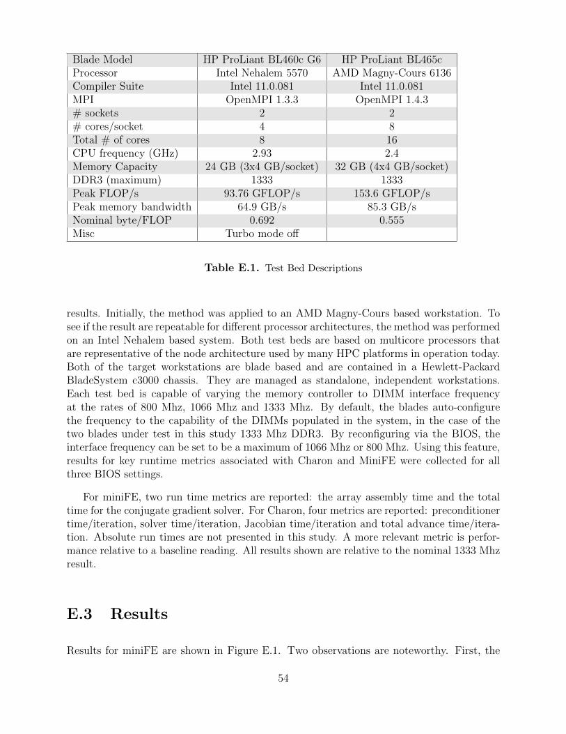
Blade Model HP ProLiant BL460c G6 HP ProLiant BL465cProcessor Intel Nehalem 5570 AMD Magny-Cours 6136Compiler Suite Intel 11.0.081 Intel 11.0.081MPI OpenMPI 1.3.3 OpenMPI 1.4.3# sockets 2 2# cores/socket 4 8Total # of cores 8 16CPU frequency (GHz) 2.93 2.4Memory Capacity 24 GB (3x4 GB/socket) 32 GB (4x4 GB/socket)DDR3 (maximum) 1333 1333Peak FLOP/s 93.76 GFLOP/s 153.6 GFLOP/sPeak memory bandwidth 64.9 GB/s 85.3 GB/sNominal byte/FLOP 0.692 0.555Misc Turbo mode off
Table E.1. Test Bed Descriptions
results. Initially, the method was applied to an AMD Magny-Cours based workstation. Tosee if the result are repeatable for different processor architectures, the method was performedon an Intel Nehalem based system. Both test beds are based on multicore processors thatare representative of the node architecture used by many HPC platforms in operation today.Both of the target workstations are blade based and are contained in a Hewlett-PackardBladeSystem c3000 chassis. They are managed as standalone, independent workstations.Each test bed is capable of varying the memory controller to DIMM interface frequencyat the rates of 800 Mhz, 1066 Mhz and 1333 Mhz. By default, the blades auto-configurethe frequency to the capability of the DIMMs populated in the system, in the case of thetwo blades under test in this study 1333 Mhz DDR3. By reconfiguring via the BIOS, theinterface frequency can be set to be a maximum of 1066 Mhz or 800 Mhz. Using this feature,results for key runtime metrics associated with Charon and MiniFE were collected for allthree BIOS settings.
For miniFE, two run time metrics are reported: the array assembly time and the totaltime for the conjugate gradient solver. For Charon, four metrics are reported: preconditionertime/iteration, solver time/iteration, Jacobian time/iteration and total advance time/itera-tion. Absolute run times are not presented in this study. A more relevant metric is perfor-mance relative to a baseline reading. All results shown are relative to the nominal 1333 Mhzresult.
E.3 Results
Results for miniFE are shown in Figure E.1. Two observations are noteworthy. First, the
54

finite assembly step is not sensitive to memory bandwidth, which implies that this step iscompletely compute bound. Second, the CG solver phase is sensitive to memory bandwidthand hence is to some degree a memory bound problem. Third, for the CG phase the AMDand Intel results are similar and hence the microarchitecture of the processor doesnt affectthe degree to which the problem responds to decreasing memory bandwidth, at least towithin a few percent. Note that this is not a statement about the absolute performance ofthe respective processors. But an observation that a given decrease in memory bandwidthhas the same relative affect on overall performance. This is a powerful observation andsupports the notion that memory bandwidth is a better indicator of performance than thecommon use of peak FLOP/s.
It’s interesting to note that on the Nehalem workstation, the assembly time is slightlyfaster at the slower 800 Mhz frequency. This is repeatable and is not a measurement anomaly.
Results for Charon are shown in Figure E.2. Again, both processor architectures reactsimilarly, within a few percent, to varying memory bandwidth. The preconditioner step isrelatively insensitive to varying bandwidth. As was seen with miniFE, the solver is the mostsensitive. The Jacobian step is unaffected, and total advance time is a function of the priorsteps and since the solve phase is the most dominant total time it also reflects the sametrend.
One of the fundamental questions when using a mini-application is - In what way doesit represent a “real” application. Above, it was shown that the calculation that is mostsensitive to memory bandwidth is the solver phase. In miniFE, a relatively fundamentalCG algorithm is used for the solver, while the Charon application, solving a nonsymmetricsystem, uses TFQMR [15] or GMRes [24]. In Figure E.3, the relative solver performance foreach is charted. These results show that in the case of the solver, miniFE is a very accurateproxy for Charon in terms of studying the affect of varying memory bandwidth. MiniFEtracks Charon’s sensitivity to within a few percent. Again, it can be seen that the resultsusing the Intel processor is consistent with that seen using the AMD processor.
E.4 Summary and Conclusions
In this study, an empirical method was used to measure the impact of main memory band-width on application performance. This was performed by varying the signaling frequencyof the DDR interface between the memory controllers and their respective DIMMs. TheminiFE mini-application and Charon application were studied. For each, metrics of interestwere identified and analyzed as the memory interface frequency was set at 800 Mhz, 1066Mhz and 1333 Mhz. Some metrics, such as assembly time in miniFE and the preconditionerstep in Charon showed to be insensitive to memory bandwidth. However, the solvers in eachapplication were sensitive to memory bandwidth. This is not surprising, but it is interestingto have a quantitative measure. It was also demonstrated that the same trends were seenusing two different workstation architectures, which provides confidence in the assertion that
55

for solver based applications the important metric is memory bandwidth, not FLOP/s. Fi-nally, it was shown that miniFE’s CG method is a good proxy for more advanced solversfound in Charon. This provides the users of miniFE confidence that memory subsystemperformance architecture studies are valid.
56

0
0.2
0.4
0.6
0.8
1
1.2
1.4
800 1066 1333
Pe
rfo
rma
nce
(R
ela
tive
to
13
33
MH
z)
Memory Frequency (MHz)
Finite Element AssemblyConj. Gradient Solve
(a) Dual-Socket, Oct-core AMD 2.4GHz Magny-Cours 6136
0
0.2
0.4
0.6
0.8
1
1.2
1.4
800 1066 1333
Pe
rfo
rma
nce
(R
ela
tive
to
13
33
MH
z)
Memory Frequency (MHz)
Finite Element AssemblyConj. Gradient Solve
(b) Dual-Socket, Quad-core Intel 2.93GHz Nehalem 5570
Figure E.1. Memory Bandwidth: miniFE Finite ElementMini-Application
57

0
0.2
0.4
0.6
0.8
1
1.2
1.4
800 1066 1333
Pe
rfo
rma
nce
(R
ela
tive
to
13
33
MH
z)
Memory Frequency (MHz)
Prec./NewtSolve/Newt
Jac./NewtAdv Time/Newt
(a) Dual-Socket, Oct-core AMD 2.4GHz Magny-Cours 6136
0
0.2
0.4
0.6
0.8
1
1.2
1.4
800 1066 1333
Pe
rfo
rma
nce
(R
ela
tive
to
13
33
MH
z)
Memory Frequency (MHz)
Prec./NewtSolve/Newt
Jac./NewtAdv Time/Newt
(b) Dual-Socket, Quad-core Intel 2.93GHz Nehalem 5570
Figure E.2. Memory Bandwidth: Charon Device Simula-tion Application
58

0
0.2
0.4
0.6
0.8
1
1.2
1.4
800 1066 1333
Pe
rfo
rma
nce
(R
ela
tive
to
13
33
MH
z)
Memory Frequency (MHz)
Charon Solve/IterminiFE CG Solve/Iter.
(a) Dual-Socket, Oct-core AMD 2.4GHz Magny-Cours 6136
0
0.2
0.4
0.6
0.8
1
1.2
1.4
800 1066 1333
Pe
rfo
rma
nce
(R
ela
tive
to
13
33
MH
z)
Memory Frequency (MHz)
Charon Solve/IterminiFE CG Solve/Iter.
(b) Dual-Socket, Quad-core Intel 2.93GHz Nehalem 5570
Figure E.3. Memory Bandwidth: miniFE compared toCharon
59

60

Appendix F
Remapping the parallel processes inCTH
This appendix expands on Section 4.3.2.
Work as part of the recently completed L2 milestone, “Report of Experiments and Evi-dence for ASC L2 Milestone 4467 – Demonstration of a Legacy Application’s Path to Exas-cale” [3] exposed a scaling issue on Cielo in the boundary exchange in miniGhost. MiniGhostwas configured to serve as a proxy for CTH. CTH, used throughout the United States DOEcomplex, and is part of the US Department of Defense (DoD) High Performance Comput-ing Modernization Program (HPCMP) test suite [9], is a multi-material, large deformation,strong shock wave, solid mechanics code developed at Sandia National Laboratories [18].Solving the Lagrangian equations using second-order accurate numerical methods and meshremap to reduce dispersion and dissipation, it includes models for multi-phase, elastic vis-coplastic, porous and explosive materials, CTH divides the domain into three dimensionalregions (illustrated in Figure 4.6), which are mapped to parallel processes. For the shapedcharge simulation considered herein, each time step CTH exchanges boundary data (twodimensional “faces”) 19 times, in each of the three dimensions, with three calls to propagatedata across faces. Each boundary exchange aggregates data from (up to) 40 arrays, repre-senting 40 variables, resulting in messages on the order of a few MBytes for representativeproblems.
The MPI rank remap strategy described in Section 4.3.2 showed a significant scalingbenefit for miniGhost. The issue was seen clearly in the time spent sending boundary datato neighbors in the z direction, illustrated in Figure 4.5(b). Its also interesting to note thatthere is no effect on the performance of the global reduction function MPI Allreduce.
We implemented this strategy in CTH, the application miniGhost was configured torepresent. Results, shown in Figure F.1, illustrate a similar benefit to the full application,demonstrating the predictive capability miniGhost is designed to provide. These runs weremade on Cielo in non-dedicated mode, so the scaling issue that seems to be appearing at 64kcores may be the result of competing jobs. Additional work in this area, including remappingof processes in the alternative SVAF strategy will be reported in subsequent publications.
61
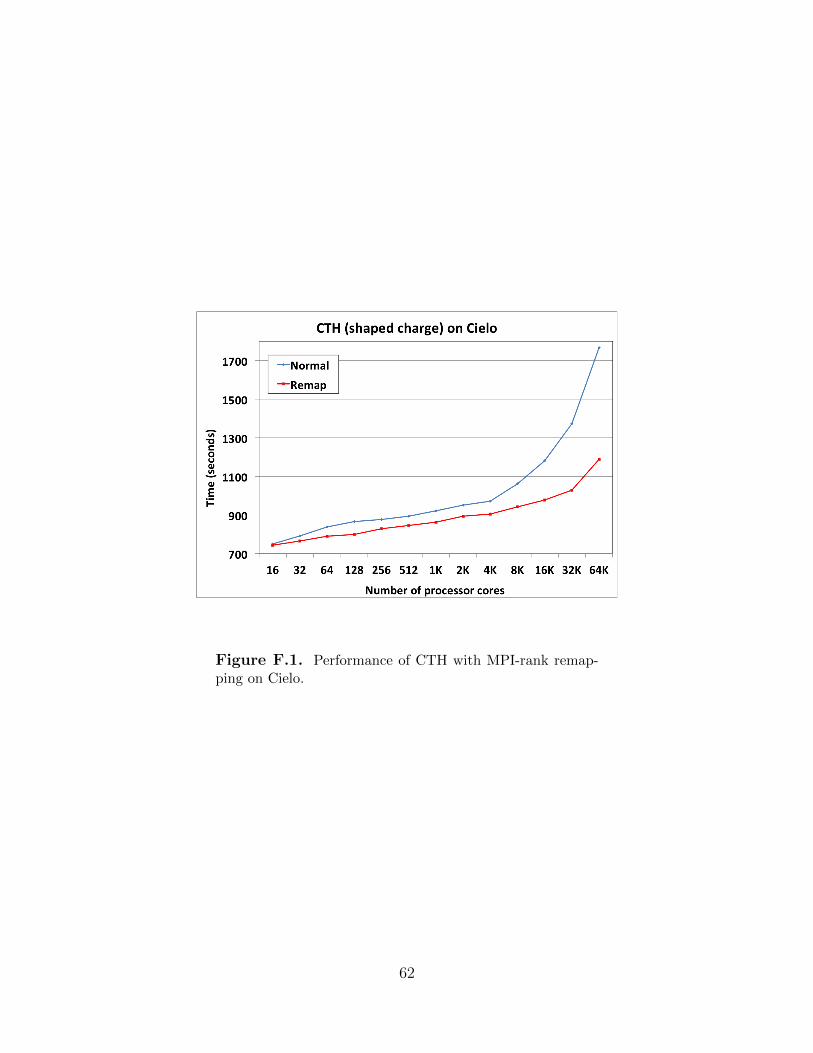
Figure F.1. Performance of CTH with MPI-rank remap-ping on Cielo.
62

Appendix G
More on Cielo
Cielo is the latest Advanced Simulation and Computing (ASC) capability machine. Althoughnot technically a testbed system since the architecture is widely available, Cielo providessome new capabilities and hardware features which we expect will be extended and refinedin future architectures.
An instantiation of a Cray XE6, Cielo is composed of AMD Opteron Magny-Cours proces-sors, connected using a Cray custom interconnect named Gemini, and a light-weight kernel(LWK) operating system called Compute Node Linux. The system, illustrated in FigureG.1, consists of 8,944 compute nodes, for a total of 143,104 cores.
Figure G.1. Cielo XE6 architecture. Image courtesy ofCray Inc.
Each Cielo node consists of two oct-core AMD Opteron Magny-Cours processors1. EachMagny-Cours processor is divided into two memory regions, called NUMA nodes, each con-
1Magny-Cours processors are also available with 12 cores divided into 6-core NUMA nodes, which formthe basis of the new Hopper II computer at NERSC (http://www.nersc.gov/nusers/systems/hopper2/).
63

sisting of four processor cores (illustrated in Figure G.2). Thus each compute node consists
Figure G.2. The XE6 compute node architecture. Imagescourtesy of Cray, Inc.
of 16 processor cores, evenly divided among four NUMA nodes, which are connected usingHyperTransport2 version 3. The links between NUMA nodes run at 6.4 GigaTransfers persecond (GT/s). Each core has a dedicated 64 kByte L1 data cache, a 64 kByte L1 instructioncache, and a 512 kByte L2 data cache, and the cores within a NUMA node share a 6 MByteL3 cache (of which 5 MBytes are user available).
Cielo compute nodes are connected using Cray’s Gemini 3-D torus high-speed intercon-nect, illustrated in Figure G.3. A Gemini ASIC supports two compute nodes. The X and Zdimensions use twice as many links as the Y dimension (24 bits and 12 bits respectively) andintroduces an asymmetry to the nodes in terms of bandwidth in the torus. This needs to betaken into account when configuring a system in order to balance the bisection bandwidthof each dimensional slice in the torus. Injection bandwidth is limited by the speed of theOpteron to Gemini HyperTransport link, which runs at 4.4 GT/s. Links in the X and Zdimensions have a peak bi-directional bandwidth of 18.75 GB/s, and the Y dimension peaksat 9.375 GB/s.
Cielo’s node interconnect, called Gemini, is configured as a three dimensional torus topol-ogy as 16 × 12 × 24.
Figure 4.4 (in the main body of this paper) shows the CTH nearest neighbor communi-cation pattern as it is mapped to Gemini’s three dimensional torus topology for Cielo.
2http://www.hypertransport.org
64

Y
X
Z
(a) Cray XE6 Gemini Architecture (b) XE6 Node Architecturewith AMD Magny-Cours pro-cessors and Cray Gemini high-speed interconnect
Figure G.3. The XE6 Gemini architecture. Images cour-tesy of Cray, Inc.
65

66

v1.37