Embed Size (px)
Citation preview
A ('()MIPARA'IIVE ANALYSIS ()F SMAILL AI)VANCEI)
NAVAL, VElICIES ANI) I)ISPL,ACEMENrI-l-lHU!I NAVAI,
SHIP )ESI(N
by
Markos Nicolaos VassilikosB.S. Marine Engineering, Hellenic Naval Academy, 1981
SUBMITTED TO THE DEPARTMENT OF OCEANENGINEERING IN PARTIAL FULFILLMENT OF THE
REQUIREMENTS FOR THE DEGREES OF
OCEAN ENGINEERand
MASTER OF SCIENCE IN OCEAN SYSTEMS MANAGEMENT
at the
MASSACHUSETTS INSTITUTE OF TECHNOLOGY
May 1989
Copyright (c) Markos Nicolaos Vassilikos, 1989. All rights reserved
The author hereby grants to MIT penrmission to r duc nd todistribute copies of this thesis document in whQe [orin[part.
Signature of AuthorDepart ent t: Ocean Engineering
May 12,1989
Certified by
Certified by
tL/'"--- -- - Professor Paul. E. SullivanThesis Supervisor
_ w
4V
Ocean SystemsProfessor Henry. S. Marcus
Management, Thesis Reader
Accepted byProfessor A. Douglas Carmichael, Chairman
Ocean Engineering Department Committee on Graduate Students
JUN 15 1989
A~FIEJg~~
A COMPARATIVE ANALYSIS OF SMALL ADVANCED
NAVAL VEHICLES AND DISPLACEMENT-HULL NAVAL
SHIP DESIGN
by
Markos Nicolaos Vassilikos
Submitted to the Department of Ocean Engineering on May 12, 1989 inpartial fulfillment of the requirements for the degrees of Ocean Engineer and
Master of Science in Ocean Systems Management.
Abstract
A small naval ship, derives its desirability as a naval vessel, due to the fact that it is aninexpensive solution to the problem of maritime defense. This thesis compares five of thesenaval vessels, two displacement-hull form, two hydrofoils, and one Surface Effect Ship.The procedure of the comparative analysis begins with a comparison of the grosscharacteristics of the ships, and uses several design indices to examine the factors thatinfluenced each design. Differences in design criteria, standards, and practices are identifiedand assessed, and the advantages and disadvantages of each design are presented.
Thesis Supervisor:Title:
Professor Paul. E. SullivanAssistant Professor of Ocean Engineering

3
A L c pc 6 V CE cr ae "TOV 1' TmT-EpC Louj KCOL,I. Zrl~r ~pc~s I~O~,
Dedi cat ed t o my f at her, and to t he memorymot her.
of my
CT Jv ~-L 1`TI9 WT

4
ACKNOWLEDGMENTS
I would like to thank the Hellenic Navy formy three years of
sponsoringst udi es i n t he U.S.
Al I the members of the MIT faculty who havecontributed to my education.
My academic advisors Professors Cl ark Graham,Tibbitts, and Paul Sullivan for passing to me t hei r
experience and insight. Paul Sullivan my thesis advisor forhis technical supervision and constructive advice.
Professor Henry Marcus, who has taught me how tomake a good group, usi ng i nst i gat i on w i t hout i nterventions.
Dr Theodosi s Bouf ounos, prof essor in the HellenicNaval Academy, for t'he inspiration he has given me.
My friend Takis Alourdas a senior officer in theHelleni c Navy, for the fruitful "compet i t i on", cooperationand conversations through the last twelve years.
Esther who suffered through t he progressthis work, and all my beloved friends who made allMIT years really happy.
Barrick
Fi nal I y, oft hese

5
TABLE OF CONTENTS
Title page
Abst ract
Acknowledgements
List of tables
List of figures
Chapter 1 - Introduction
1.1 Purpose of the study
1 .2 Rationale for ship selection
1.3 St udy approach
1 .4 Sources for the study
Chapter 2 History of small combatants
2.1 The pl ani ng hul I form and HSD vessels
2.2 The hydrofoils
2.3 The SESs
Gross ship description
1
2
3
11
12
16
16
16
19
20
21
22
24
24
Chapt er 3 26
6
Chapter 4 - Overall analysis of ships
4.1 Gross characteristics
4.1.1 The CPIC
4.1.2 The SPICA i
4.1.3 The PHM
4.1.4 The M161
4.1.5 The APB34
4.2 Comparison by weights
4.2.1 Weight allocation
4.2.1.1 SWBS Group 100
4.2.1.2 SWBS Group 200
4.2.1.3 SWBS Group 300
4.2.1.4 SWBS Group 400Survei II ance)
4.2.1.5 SWBS Group 500
4.2.1.6. SWBS Group 600
4.2.1.7 SWBS Group 700
4.2.1
4.2.2
4.3
4.3.1
fraction
(Hull St ruct ures)
(Propulsion Plant)
(Electric Plant)
(Command and
(Auxiliary systems)
(Out. and furnishings)
(Armament)
.8 Loads and margins fraction
Absol ute scale weight s
Volume comparison
Mission support (V1)
33
33
33
36
36
37
37
38
38
38
38
39
39
39
40
40
41
41
41
42
7
4.3.2
4.3.3
4.3.4
4.4
4.4.1
4.4.2
4.4.3
4.4.4
4.5
Personnel support (V2)
Ship support (V3)
Ship mobility system (V4)
Weather deck pace comparison
Weapons/ Sensors fraction
Superstructure fraction
Boat s and repl eni shment at sea f ract i on
I nt ake and exhaust f ract i on
Chapter conclusions
5 - Design indices by f unct ional area
Mobi I ity
.1 Speed
.1 .1 Hydrodynami c ef f i ci ency
.1.1 a Propulsive coefficient
.1.1 b Lift to drag ratio
.1.2 Mai n propul sion weight specif ic rat i o
.1.3 Design budget
.1.4 Conclusions
.2 Range
.2.1 Stores endurance
42
43
43
44
44
45
45
45
46
49
50
50
52
52
53
55
56
56
60
60
Chapter
5.1
5.1
5.1
5.1
5.1
5.1
5.1
5.1
5.1
5.1
8
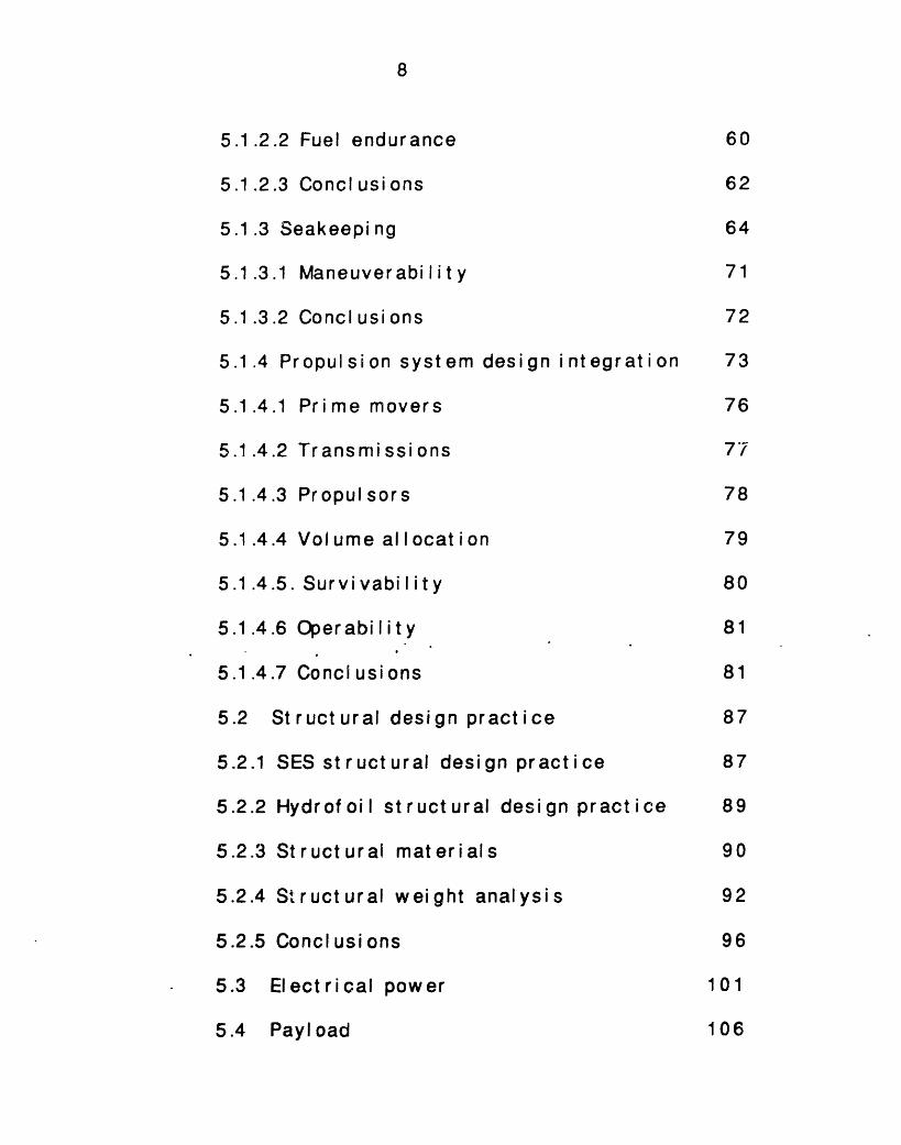
5.1.2.2 Fuel endurance 60
5.1.2.3 Conclusions 62
5.1.3 Seakeeping 64
5.1.3.1 Maneuverability 71
5.1.3.2 Conclusions 72
5.1.4 Propulsion system design integration 73
5.1.4.1 Prime movers 76
5.1.4.2 Transmissions 77
5.1.4.3 Propulsors 78
5.1.4.4 Vol ume al I ocat i on 79
5.1.4.5. Survivability 80
5.1.4.6 Operability 81
5.1.4.7 Conclusions 81
5.2 Structural design practice 87
5.2.1 SES st ruct ural design pract ice 87
5.2.2 Hydrofoil structural design practice 89
5.2.3 Structural materials 90
5.2.4 Structural weight analysis 92
5.2.5 Conclusions 96
5.3 Electrical power 101
5.4 Payl oad 106
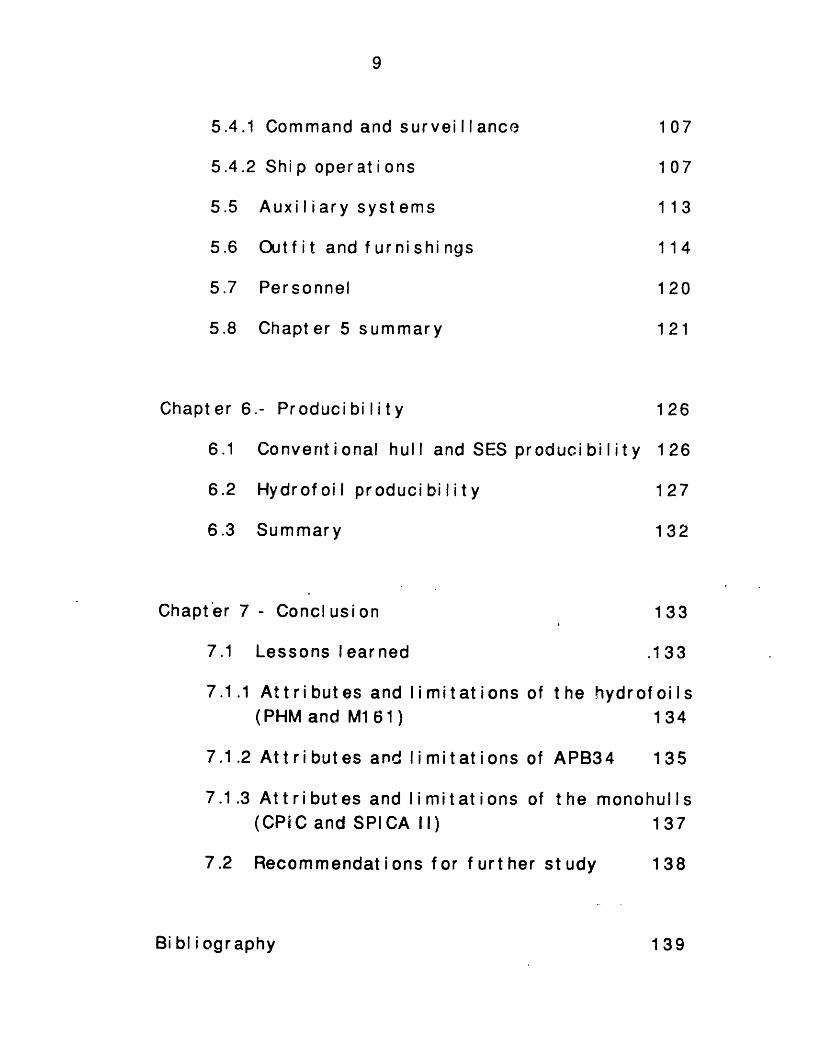
9
Command and surveill ance
Shi p oper at i ons
Auxiliary systems
Outf i t and f urni shi ngs
Personnel
Chapter 5 summary
Chapt er
6.1
6.2
6.3
Chap
6.- Producibility
Conventional hull and SES producibility
Hydrofoil producibility
Summary
ter 7 - Conclusion
7.1 Lessons learned
7.1.1 Attributes and limitations of the (PHM and M1 61)
7.1.2 Attributes and limitations of APB3
7.1.3 Attributes and limitations of the (CPiC and SPICA II)
7.2 Recommendat ions for f urt her study
126
1 26
127
132
133
.133
iydrof oils134
14 135
nonohul I s
137
138
Bibliography
5.4.1
5.4.2
5.5
5.6
5.7
5.8
107
107
113
114
120
121
139
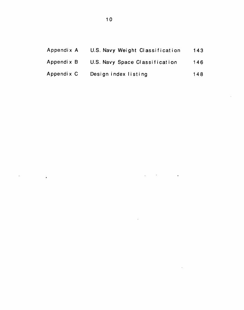
10
Appendix A
Appendix B
Appendix C
U.S. Navy Wei ght Cl assi f i cat i on
U.S. Navy Space Classi f i cat ion
Design i ndex I i sti ng
143
146
148
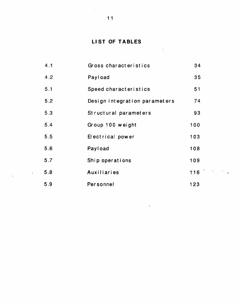
11
LIST OF TABLES
Gross char act eri st ics
Payload
Speed charact eri st ics
Design integration parameters
Structural parameters
Group 100 weight
Electrical power
Payload
Ship operat ions
Auxiliaries
Personnel
4.1
4.2
5.1
5.2
5.3
5.4
5.5
5.6
5.7
5.8
5.9
34
35
51
74
93
100
103
108
109
116
123
12
LIST OF FIGURES
1.1 The sustention triangle 18
2.1 Typical planing hull forms 23
2.2 Typical HSD hull forms 23
3.1 CPIC 27
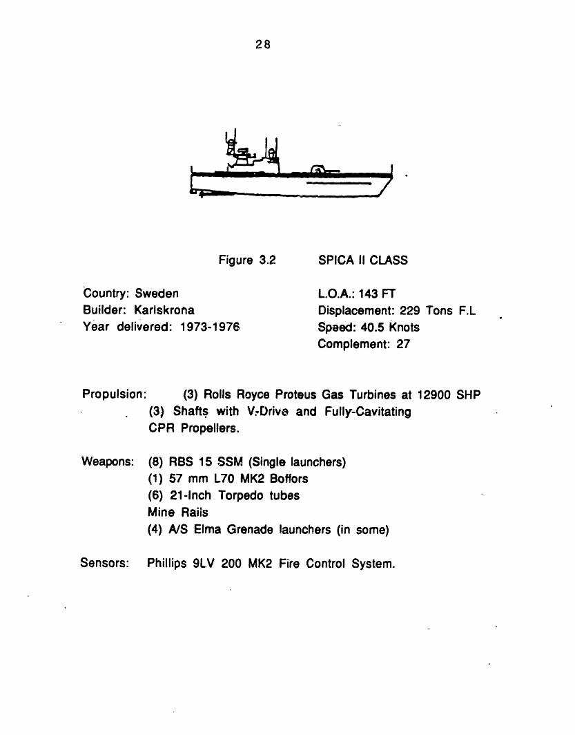
3.2 SPICA II Class 28
3.3 PHM Hydrofoil Class 29
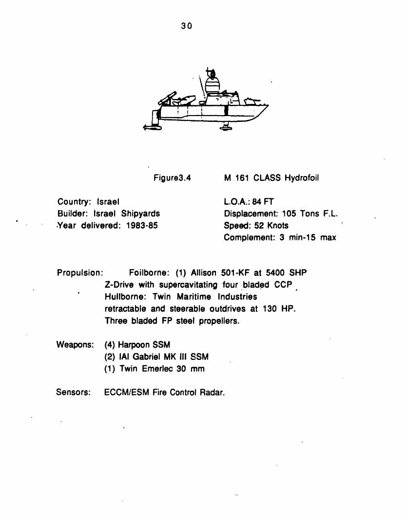
3.4 M161 Hydrofoil Class 30
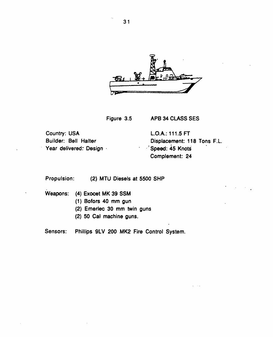
3.5 APB34 SES Class 31
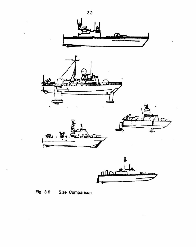
3.6 Size comparison 32
4.1 Weights fraction 47
4.2 Full load weights 47
4.3 Volume allocation 48
4.4 Weat her deck space all ocat i on 48
13
5.1 Main propul si on wt specific rat i o vs.Displacement 58
5.2 Main propulsion specific wt vs. Max speed 58
5.3 (PC* L/ D)/ (W2/ SHP) vs. Pr opul si ve Ef f i ci ency 59
5.4 Mai n propul si on wt f ract i on vs. Max speed 59
5.5 SFC vs. Mai n propul si on wt speci f i c rat i o 63
5.6 Fuel wt fraction vs. Max speed 63
5.7 Speed wave envelope 65
5.8 Speed vs. Significant wave height 67
5.9 Human response t o vert i cal accel erat i on vs.Frequency and Exposure time 68
5.10 Main propulsion ship size ratio vs. Max speed 82
5.1 1 Tot al HP shi p si ze rat i o vs. Di spl acement 82
5.1 2 Max speed vs. Transport ef f i ci ency 83
5.13 Mai n propul si on wt f ract ion vs. Transportefficiency 83
5.14 Mai n propul si on vol ume f ract i on vs. Di spl. 84
5.1 5 Main propulsion density vs. displacement 84
5.16 SPICA II machinery room 85
5.17 CPIC machinery room 85
5.18 M161 machinery room 86
5.19 PHM machinery room 86
14
Hull structure wt fraction vs. Displacement
Ship dens
St ruct ura
Group 100
Structuralspeed
El ect r ical
El ect r ical
Payload elfraction
Elect r ical
Payload w
Armament
Armament
it y vs. Displacement
I wt specific ratio vs. Displacement
weight fraction
I and propulsion wt fraction vs Max
w t f ract ion vs. Di spl acement 1
wt specific ratio vs. Displacement
ectric efficiency vs. Electrical wt
power ship size ratio vs. Displ. 1
eight f ract ion vs. Max. speed 1
wt fracti.on vs. Displacement 1
wt specific ratio vs. Displac. 1
Payl oad wt f raction vs. Transport ef ficiency
Command and surveillance wt fract. vs.Di spl acement
Mi ssi on support f ract i on vs. Max speed
Auxi I i ary systems wt f ract i on vs. Di spl ac.
Auxi I i ary syst ems speci f i c r at i o vs.Di spl acement
Shi p support vol ume f ract i on vs. Di spl ac.
1
1
1
1
1
1
97
98
98
99
104
105
05
06
10
10
11
111
12
12
17
17
18
5.20 97
5.21
5.22
5.23
5.25
5.26
5.26
5.27
5.28
5.29
5.30
5.31
5.32
5.33
5.34
5.35
5.36
5.37
15
5.38 Out f it and f urni shi ngs wt f ract ion vsDi spl acement 118
5.39 Payl oad vs. Auxi I i ary and out f i t t rade- of f 1 1 9
5.40 Manni ng- shi p si ze rat i o vs. Di spl acement 1 24
5.41 Personnel volume specific ratio vs. Displ. 124
5.42 Personnel vol ume f ract i on vs. Di spl acement 1 25
6.1 SES modular breakdown 128
6.2 PHM modular assembly 130
16
CHAPTER 1
INTRODUCTION
1. !Pr rLzseAf t h t uSLdy
Tradi t i onal I y, at tent ion has been focused onrequirements and developments of large ships. In the lasttwenty years, however, significant changes have occurredin the development and use of fast patrol boats. The famedPT and E boat s of World War II spawned a second generation
of missile-armed boats that emerged in the late 1950's and1960's and have generally been referred to as Fast PatrolBoat s (FPBs).
This thesis studies and compares some of the latestversions of FPBs. The ships of- the study represent eachhull technology currently used for FPBs. The differences indesi gn and const ruction between two conventional(displacement), two hydrofoil and one SES ship design arepresented. The differences in the ships are analyzed asthey are presently constructed, and the differences in thedesign criteria and standards (evidenced as differences indesign indices) are tabulated by functional area to allow asi de- by- side comparison.
12 Ratinnalt__r__ sh ilsLet LnThe comparat i ve anal ysi s cf t hi s st udy i s focused to a
full load displacement range of 70 to 250 tons. The basicidea is to cover three different small naval ship-designs:one "conventional", and two different "high performance"
17
(hydrofoil and SES) designs. For every design, one ship of
about 100 tons full load displacement is evaluated. In thearea of 230 tons full load weight one hydrofoil and one"conventional" vessel are examined.
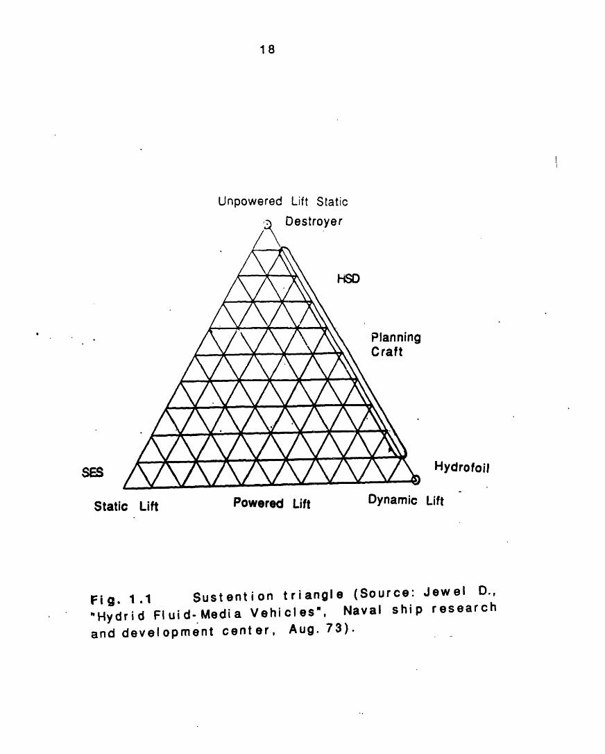
The method chosen to categorize the vessels, is thatof the identification of the supporting force or sustention.
There are three different types of sustent ion:
Unpowered St at i c Lift
Powered Dynamic Lift
Powered St at i c Li ft.
All the vessels of the study operate by one of thesethree forms of supporting force or some combination ofthese forms. (See figure 1.1). Unpowered static lift is acharact er i st i c of large di splacement t ype shi ps. Hydrof oi I soperate with powered dynamic lift, and SESs are an
. example of the powered static Jift type of vessels. Planingcraft generate dynamic lift forces at high speeds, as theyenter the planing regime. Finally, high-speed displacementvessels could be placed in the unpowered static lift-pl ani ng region.
Fi rst, t he two hydrof oi I s were sel ect ed. The hydrof oi Ilmenu was limited due to the small amount of hydrofoiltypes in the naval market t oday, as well as therest r ict ions imposed by t he unavailabi I ity of classif ied orproprietary information. PHM (U.S.A), and M161(Israel)were selected, covering the range of 70 to 250 tons. Forconventional hull types, CPIC (U.S.A for South Korea), andSPICA II (Sweden) were picked in order to allow a
PHM, correspondingly. For thecomparison with M161 and
18
Unpowered Lift Static
Destroyer
HSD
PlanningCraft
SES Hydrofoil
Static Lift Powered Lift
Sustention triangled Fluid-Media Vehicles",
(Source: Jewel D.,Naval ship research
Aug. 73).and development center,
Dynamic Lift
.1Fig. 1"Hydri
I
19
SES design, APB34 (a Bell Halter design) was chosen, at thesame full load displacement as M161.For this study, U.S.and foreign constructors were selected in order to give af I avor of t he dif ferences i n t he desi gn phi I losophy of smal Icombat ant s of U.S. and f or ei gn navi es.
.l3 _itPu dLairacbAt first, a
five differentcomparison of the gross descriptionships is made. Later an analysis
weight andthe weightparamet ersi ndi ces arecharacteri sicombi nat i ona quant itatdesign critE
volume utiiizat i c
and volume anal(design indices
e rat i os of votics such as crewis of the above. Tive measure oferia, as well as
)n is made. As a derivative ofysis, a collection of specific) is developed. The designlume and weight or ot her
size or shaft horsepower, orhese specific parameters give
the ships' characteristics,ship performance. The design
indices used in thi s study can. be found in Appendix C.Although t'he analysis occupies three different ship types,many common characteristics are realized, and these arepresented as trends by mission or by size.
Finally, producibilit y aspectsspeed displacement hull, hydrofoilpresented.
of the planing and highand SES ship design are
The design indices forusing the information prUnf or t unat el y, t here w as no
each type of ship are derivedesented in the bibliography.response f rom the shi pbui I ders
of theof the
1L4 2Ier es nr -1 X-ad
20
(requested to provide more details about every ship) due toprobl ems with propriet ary inf or mat ion.
Reference 24 provided most of the design indices forthe conventional hull vessels and PHM. The AdvancedSurface Ship Evaluation Tool (ASSET) for hydrofoil designwas used to obtain the indices for the two hydrof oils. Thedesign characteristics of PHM and M161 were used as input,and two "new" designs were derived. The accuracy of theresults obtained f rom ASSET was verified, after comparingthem with the information found in the correspondingbibliography .
For t he SES design, reference 44 was used. Many of t hedesign indices were provided from t he SES design group ofNaval Sea Systems Command. The information from NAVSEAwas not focused on APB34 design, but on the design of asimilar naval vessel, of the same role, displacement,payload, maximum and endurance speed, and range. Thedesign indices of APB34 contain a larger amount of error,compared to the design indices of the other vessels, asthey representhaving years of
a design, and not a tested fightingservice at sea.
Volumes and areas for all the vessels were measuredby the writer from the corresponding drawings, or takenfrom the papers in the bibliography, or derived by ASSET.The deck space areas of the vessels presented in chapter 4were measured by the writer.
shi p
21
CHAPTER 2
HISTORY OF SMALL COMBATANTS
Since their introduction in the 1950's, fast patrolboats have become an increasingly important part of theworld's navies. Many nations have found them an attractivealternative to surf ace combatants due to their lower costand efficient use of manpower and budget. Countries arebecoming increasingly aware of the capability of this typeof vessel, and the need for such a capability in order tomeet the pressure exerted on the modern navy operating inthe regional or even global environment.
The missions that a modern navy is required to meethave expanded greatly, both in number and comp!exity.Historically, most nations have required coastal patrolwithin a limited perimeter, typically 3 to 12 miles. Theadvent of the 200- mile limit has expanded this area to apoint where only comparatively large numbers of high-speed vessels equipped with the most sophi st i cat edelectronics and weapons are able to cover it adequately.Since destroyers, frigates, and even corvettes are far toocostly to be acquired in sufficient quantity to meet thischal I lenge, t he f ast pat rol / at t ack craf t has been adopt ed bymany navies.
In some navies, fast patrol craft often constitute theent i re sea- deni al f orce, wi t h t he occasi onal except i on of afew corvettes. Some nations have developed extremelyeffective navies based entirely on FPBs which haveprovided graphic evidence of the validity of--t-he FPBconcept, even against much larger displacement vessels.
22
Perhaps the most persuasive evidence of the successof fast patrol/attack craft is the sheer magnitude of theirdistribution. There are over 2000 FPBs in service aroundthe world, and several hundred more are on order.
As the FPBs were evolving, the electronics andweapons systems associated with them have progressedrapidly as well. There are increasing numbers o highperformance advanced weapons syst ems specifical Iydesigned for installation on FPB hulls. Surface-to-surfacemissiles, introduced on FPBs by the Soviet Union in 1959,have proven their effectiveness several times over. Rapidrate-of-fire guns are mandatory for anti-aircraft andanti-missile defense, in addition to their roles as anti-surf ace and ai di ng f orce support. Sophi st i cat ed el ect roni csand fire control systems are necessary to handle all ofthese equipments, and they are even more complex as theavai I abl e react i on t i me drops.
2.1 TIhe PaLninaL hlLLwL-m LandSLD vessels
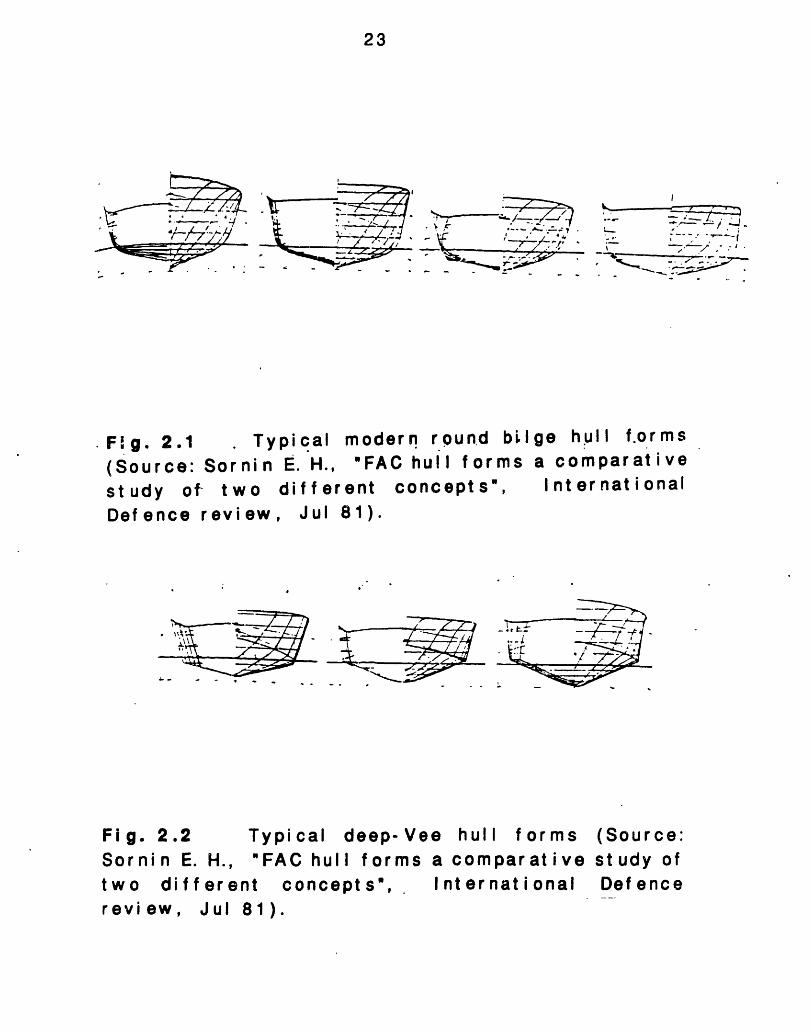
Since the early 1900s there has been little change inthe basic underwater-hull forms used in the design of fastNaval vessel s, al t hough t here has been not abl eimprovement in hull lines. Thus there is remarkably littledifference in either hull form or performance between theTurbinia, Sir Charles Parsons' forerunner of the Steam-turbine-powered ship, which made 36 kt in 1896 andcontemporary Fast Attack Crafts (FACs) with round-bilgehulls. Typical round-bilge hull forms, and classical planinghull forms are presented in figures 2.1 and 2.2.
Although the the fast attack craft is limited in manyrespects by its small size compared with corvettes and
23
I
._ -. -- I. r , ,7 . _-
.Fg. 2.1(Source:study oDefence
TylSorni n
f two revi ew,
pi calE. H.,
diffeJul
modern round bil'FAC hull forms
rent concepts",81).
ge hull f.ormsa comparativeInternational
, .- -
Fig. 2.2 Typical deep-Vee hull formsSornin E. H., FAC hull forms a comparativetwo different concepts", Internationalreview, Jul 81).
(Source:st udy ofDefence
24
frigates,platformnumbers,
theis
and
cost effectiveness of this tleading to its procurement
to a profusion of new designs i
ype of weaponin increasing
n the market.
a2.. THIdYrQdi2L2LLs
A United St at es patent for a hydrofoil was filed in thelate 1880s, about the same time as the early airplane andai rf oi Ipatents. The earliest record of a successfulhydrofoil flight is 1894 at Chicago, Illinois. The earlyattempts to exploit the hydrofoil concept were frustratedby the lack of suitable structural materials and powerplants. Advancement in these areas has permitted thedevelopment, over the past 30-40 years, of the technologynecessary t o achi eve rel i abl e and ef f ect i ve hydrof oi I shipsfor military operations.
In recent years, many countries have demonstrated aninterest in applying hydrofoils to military missions. Italyhas been devel opi ng i t s class of f ul I ly submerged hydrof oi l ssince the early 1970s. Israel contracted for its firsthydrofoil in 1977. Hydrofoils are under construction inIndonesia. The Soviet Union leads the world with activehydrofoil development from the end of World War II. Todaythe USSR has the largest number of hydrofoils, military andcivilian in the world.
a.ATIhgSE1
The technologyhovercraft, has been30 years. ExperimeiBritain and the US.
ofun(
nt alin
SES and its closeder development for
prototypes havethe late 1950's and
relative, theapproxi mat el ybeen built inearly 1960's.
25
Operationally useful craft from 5 to 200 tons have beenapplied to both commercial and military missions since themiddle to late 1 960's.
The more ef f i ci ent SES was i ni t i al I ly developed i n t heUnited States and Britain in the early 1960's. In the UnitedStates a joint program was initiated by the MaritimeAdministration, which funded the construction of two 100-ton SES test craft during 1969-71. These craft, the SES100-A built by Aerojet General Corporation and the SES-100B built by Bell Aerospace Textron, underwent extensivetesting and operational evaluation through 1977. Later SESdesigns include the SES 200, the Model 522A Coast GuardSES (delivered in 1982), and the Model 511A Fast PatrolCraf t .
26
CHAPTER 3
GROSS SHIP DESCRIPTI ON
Thi seach shipreader wi
chapter is comprised of a brief description ofincluded in the study, in order to familiarize theth the ships.
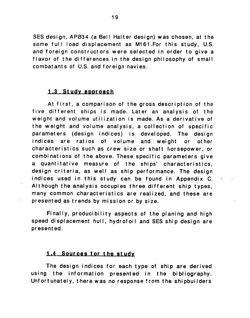
In figures 3.1 throughship are presented, inwere const ructed and
3.5 the gross characteristics of eachaddition to the country for which thetheir delivery period.
Figure 3.6 presents the ships as tdry dock next to each other in a scaleorder for t he reader to gain an idea of ttheir relative size.
hey could appear inratio of 1/400, in
heir appearance and
27
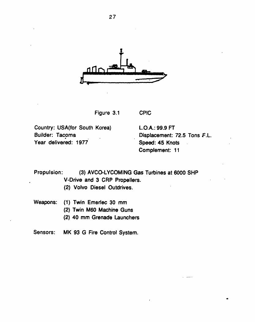
Figure 3.1
Country: USA(for South Korea)Builder: TacomaYear delivered: 1977
Propulsion:
L.O.A.: 99.9 FT
Displacement: 72.5 Tons F.L.Speed: 45 KnotsComplement: 11
(3) AVCO-LYCOMING Gas Turbines at 6000 SHPV-Drive and 3 CRP Propellers.(2) Volvo Diesel Outdrives.
Weapons: (1) Twin Emerlec 30 mm
(2) Twin M60 Machine Guns(2) 40 mm Grenade Launchers
MK 93 G Fire Control System.
CPIC
-r r r -- sk mh- ---
Sensors:
28
Figure 3.2
Country: SwedenBuilder: KarlskronaYear delivered: 1973-1976
SPICA II CLASS
L.O.A.: 143 FT
Displacement: 229 Tons F.LSpeed: 40.5 KnotsComplement: 27
Propulsion: (3) Rolls Royce Proteus Gas Turbines at 12900 SHP(3) Shafts with VDrive and Fully-CavitatingCPR Propellers.
Weapons: (8) RBS 15 SSM (Single launchers)
(1) 57 mm L70 MK2 Boffors
(6) 21-Inch Torpedo tubesMine Rails
(4) A/S Elma Grenade launchers (in some)
Phillips 9LV 200 MK2 Fire Control System.Sensors:

29
1e,.
Figure 3.3
Country: USABuilder: Boeing Aerospace
'Year delivered: 1977-82
PHM CLASS Hydrofoil
L.O.A.: 132 FTDisplacement: 241 Tons F.L.Speed: 50 + KnotsComplemeit: 21-24
Propulsion: Foiborne: (1) LM 2500 at 17000 SHPDriving a single foilborne propulsion pump.Hullborne: (2) Mercedes-Benz Diesels at 1600 SHPDriving twin Aerojet pumps.
Weapons: (8) Harpoon SSM(1) OTO MELARA 7 6mm gun.Can be delivered with (2) MK20 RH 202 20mmSecondary guns.
Sensors: WM-28 Weapons Control or Mk 92 (Mod I)
30
Figure3.4
Country: IsraelBuilder: Israel Shipyards*Year delivered: 1983-85
Propulsion:
M 161 CLASS Hydrofoil
L.O.A.: 84 FT
Displacement: 105 Tons F.L.Speed: 52 KnotsComplement: 3 min-15 max
Foilborne: (1) Allison 501-KF at 5400 SHPZ-Drive with supercavitating four bladed CCPHullborne: Twin Maritime Industriesretractable and steerable outdrives at 130 HP.
Three bladed FP steel propellers.
Weapons: (4) Harpoon SSM
(2) IAI Gabriel MK III SSM
(1) Twin Emerlec 30 mm
ECCM/ESM Fire Control Radar.Sensors:
31
Figure 3.5
Country: USA
Builder: Bell HalterYear delivered: Design ·
Propulsion:
APB 34 CLASS SES
L.O.A.: 111.5 FT
Displacement: 118 Tons F.L.' Speed: 5 KnotsComplement: 24
(2) MTU Diesels at 5500 SHP
Weapons: (4) Exocet MK 39 SSM
(1) Bofors 40 mm gun(2) Emerlec 30 mm twin guns
(2) 50 Cal machine guns.
Phillips 9LV 200 MK2 Fire Control System.Sensors:
32
i 1-6- ---
Fig. 3.6 Size Comparison
and
aaQ- -.01

33
CHAPTER 4
OVERALL ANALYSIS OF SHIPS
This chapter compares the overall design features ofthe ships. In order to start analyzing the ships, the designdifferences in full load weights, weight, volume, and deckspace allocation fractions, as well as, the overall designcharacteristics should be examined on a gross level.Further in depth analysis of the results of this chapterwill be presented in following chapters.
4 1_f .S.. 5 B RACIELEB LST LCS
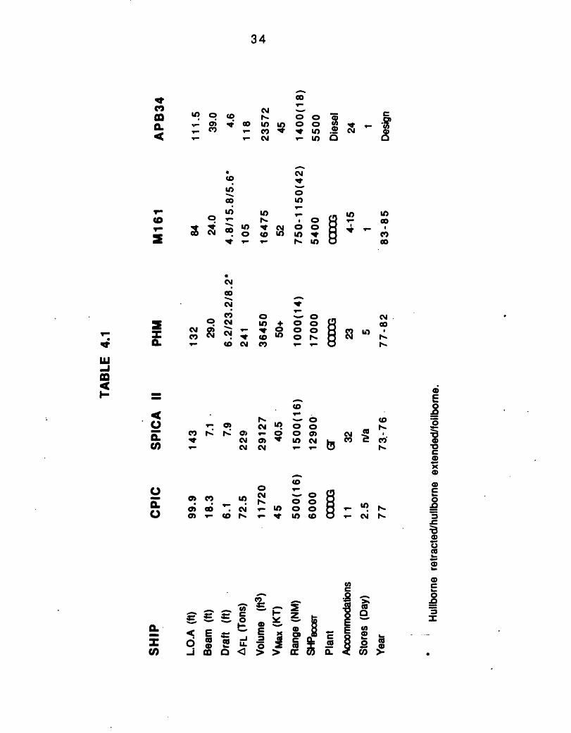
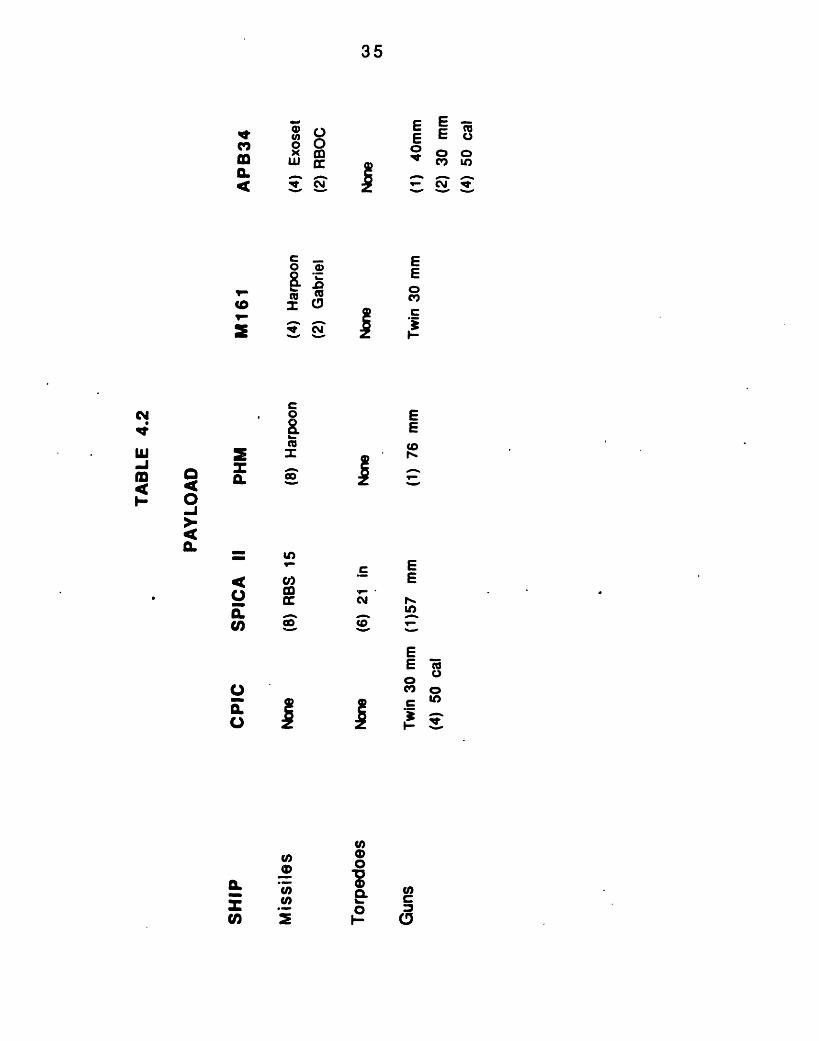
The maj or charact er i st i cs of t he vessels are show n i ntable 4.1. The first two vessels are of the monohull design(the CPIC and the SPICA II). After the monohulls the twohydrofoil s, PHM and M161 are presented. The final vessel isthe SES design (APB34). The ships' payload is presented int able 4.2.
4.1.1 The CPIC
This short ship, built by Tacoma shipyards for theSouth Korean Navy in 1977 is a short range, high speedpat rol craft designed for coastal mi ssi ons. Itssophisticated all-gun armament, shallow draft, and highspeed make CPIC ideally suited for "guerrilla" warfareoperations, insert ion, and small pat rol boat actions.
co
:g ,V- g) a
(0w'i co
V
0
~D:0U;
cou_IDV
E
a Ra cIL °
cn
C.)D,
C6
cm
CI
N CI
0)v CY_rl CY
O C) U)0 0 . ._0 -. C0
M _- o Pj
LO
C)
U) +( 0W to
0Cl
I.
o4U) tfl W)
In0CO0
-N
0 0 c00 -_- _- r
co
W-
cDC) 00_U V O O
(D
co ro CY
9- N -
E
.8
o.5ix
CD
C)F.8
' 00;a
0)O..
.)s.-
IC')C
ILI 3=~ * a 3 S ,_ e _ LL 4
U) 0 a < > >0 m CL C'
34
leCv,
in.4. 0
I.-
cm
C
CI cocm
LU-J1m
I--
35
X3 oOm us =Mr 00.0
IV Cu
C0 m
.
-
a XE m_ CoR
n,m0 3
IC.>0E
U)I0
E E EEU
I- -. SoE C
EE0C
EE
C EE
_ .Lo
EE X
o
0
0C:3
CD
Nui
-JI-.
a0-IIp0.
36
4.1.2 The SPICA II
This is a Swedish ship built by Karls.krona Varnetbetween 1973-76. The SPICA II differs in appearance fromother ships of the similar type, as it has a small deckhouseset far aft. The ships of this design underwent majormodifications in 1984. SSM missile launchers were fittedwith new CIC modernized electronics and a new 57mm gunand hull mounted sonar. These ships have been built andthen modernized for surface and underwater surveillance inthe restricted waters around Scandinavia.
4.1.3 The PHM
origimi ssthecompshipsup to
The NATO Fast Patrol Shipnated in mid-1969 to coile-armed Soviet Osa/Kom;Medi t er r anean w at er s.
ileted its acceptance trialof this design were built1982.
The PHM h.
individual comtit can be adaptefisheries lawresources. In tlnavy will be prwith fast carriand amphibiousref uel I i ng
Guided miDmbat t hear type f asThe firsts on June
by Boeing
as sufficient design flexibi)at systems variations by ed for such roles as ant isuenf orcement, and protect
his study the design now aesented. PHM is capable ofer task groups, convoys ofassault groups, with the
ssile (NATO/ PHM)t hreat posed byt patrol boats in
PHM, Pegasus,1977. Five otherMarine Systems,
lity to allow forany country. Thusbmarine warfare,ion of offshorelctive in the U.S.
crossing oceansf merchant shipsaid of an at-sea
The M161
The AerospaceTwo moreLimited, in
first M161,Corporation,M1 61 s havelater years.
Shimrit, designed by Grummanwas launched in Florida in 1981.been built by Israel Shipyards,
The M161 is a very powerfully-armed strike vessel.Its operation as a "day- boat" has had a significantinfluence on the choice of the ship's syst ems andarrangements. The M1 61 has been designed for a wide rangeof military roles, and can be fitted with a variety ofweapons. Designs are available wit h dif feri ng payloads andendurances for appl i cat i ons including gunboat, trooptransport, surveillance craft, missile boat, inshore ASWpatrol, EEZ patrol and search and rescue.
4.1.5 The APB34
APB34 is aventure of Bel Iservices, Inc.
design created byAerospace Textron
Bell- Halt er,and Halt er
a jointMari ne
APB34 design represents an improvement over thesuccessf ul SES- 1 00B design.
APB34 offers a greater speed for a given horsepower,with better seakeeping and platform stability, particularlyin high sea states. Its greater deck area enables awesomeconcentration of fire power capability, provided that thedesi gner can f i t t hem weight- w i se.
37
4.1.4
38
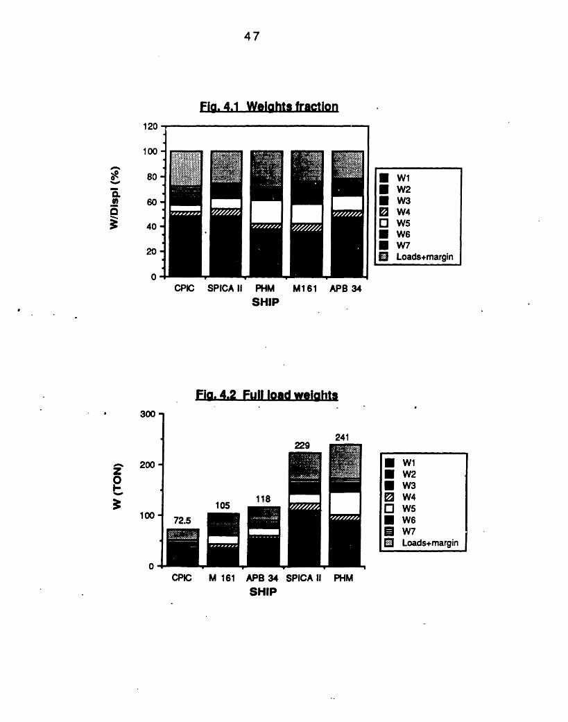
4,2C MEARLS_YIE GHTS
In order to be able to categorize all weight indicest he navy w ei ght cl assi f i cat i on syst em Shi ps WorkBreakdown Structure (SWBS) is used (See Appendix A).Further information about this system may be found inreference 21. The weight allocation fraction for each shipcan be seen in figure 4.1 The weight breakdown for eachship i n absol ute scale can be found i n figure 4.2.
4.2.1
4.2.1.1
Weight all ocat i on f ract i on
SWBS Group 100 (Hull st r uct ures)
The advantage of the Aluminum construction can beeasily seen, comparing the hull structure fraction. SPICAII, an all Steel vessel, has 36 % of its overall weightdedicated to structure, leaving less weight fraction forother areas. The same advantage exists for the hydrof oils,al t hough t hei r hul 1, must have addi t i onal' st rengt h t o resi stwave impact and emergency landing in high seas atfoilborne speeds. The advantage of the Aluminum hullcannot be seen in APB34 as the safety factors used in SESstructural designs are larger than those of the monohulls.The SES design of our study needed large safety factors inorder to provide a reasonable margin to account forunknowns in the design process, due to the limitedexperience from the SESs that are already at sea.
4.2.1.2 SWBS Group 200 (Propulsion plant)
The i ncorporat i on of the di esel s for -hullbornepropulsion drives the weight group 200 fraction of the PHM
39
up.theCPI
The t hree gas t urbi nes and t he V- dr i ve of t he CPIC havesame effect as above, although they make the small
C a very fast craft.
4.2.1.3 SWBS Group 300 (Electric plant)
The group 300 wei ght f ract i on i s a di rect consequenceof the payload each ship can carry. The M161 an extremelypowerful vessel, has the biggest fraction as it is carryingtwo big generators to fulfill its payload requirements. Theminimal discrete generator size of the CPIC, results in acompar at i vel y hi gh el ect r i c plant w ei ght f ract i on.
4.2.1.4 SWBS Group 400 (Command and Surveillance)
M161 with a large radome on the deckhouse has thehighest group 400 weight fraction. SPICA II comes next,having undergone major modifications lately, as Europeanst end to emphasize command and surveillance more than theU.S. designers. Excluding the CPIC, the other two Americandesigns have the similar group 400 weight fraction.
4.2.1.5 SWBS Group 500 (Auxiliary systems)
The two hydrofoils have the higher group 500 weightfraction, as they need very powerful hydraulic systems fort he demands of t heir control systems, in both hull borne andfoilborne operation. The multiple levels of redundancyneeded to assure continued operation in the event ofsystem failure, drive the auxiliary systems weight-up.
40
The M161 has a lower group 500 fraction thanthe PHM as it has to support a much smaller crew.fans are the major contributors to the increaseauxiliary systems weight fraction in the APB34. Smuch larger than the CPIC, with a lengthier missirequirement to support a larger crew, has aaux i I i ary syst ems w ei ght f ract i on.
4.2.1.6
t hat ofLiftingof the
PICA II
on, andlarger
SWBS Group 600 (Out fit and f urni shi ngs)
CPIC, due to its size and its short mission, and M161,due to its very small area devoted to personnel, as well as,its short mission have the smaller group 600 weightfraction. The M161 fraction is very small, as crewcomforts take second place in this ship. The other vesselshave approximately the same outfit and furnishings weightfraction, with the more "spacious" European design SPICAII devot i ng a larger f ract i on t o t he group 600 wei ght s.
4.2.1 .7 SWBS Group 700 (Armament)
The variation from 3.6% to 15.2% isi ndi cat or of combat i bi I i t y, since volumesystems is more important in some of themust be noted that the heavily loaded, for ihas t he bi gger ar mament w ei ght f ract i on
not a goodof weapon
ships. But itts size M161
41
4.2.1.8 Loads and margi ns f ract ion
When the Group 100- 700 weights are subtracted fromf ul I load di splacement t he remai ni ng wei ght s are t he I oadsand margins.
4.2.2 Absol ute Scale Weights
Figure 4.2 presents the distribution of the ship'sw eight s i n absol ut e scal e.
The group 1larger than thatapproximately thhappens to the gr to its large hydraweight. The weiglthan that of the S
00 weight of SPIof the PHM, al t
e same full load)up 200 weight of tlulic system has aht of t he loads carPICA II.
CA II is significantlyhough the ships haveweight. The opposite
he two ships. PHM, duemuch bigger group 500'ried by PHM is bigger
Comparing APB34approximately the samemention the group 100reasons explained earlie
and M161, vessels wfull load displacement,weight of the APB34
r in this chapter.
hi cwe, f
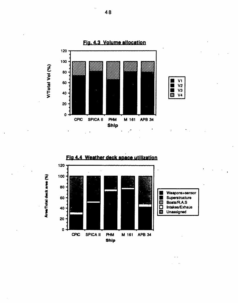
3V OLMECMPRLA I SON
The di missionin theinternaldividedAppendi(Human
ferent designcharacteristicallocation of
volume devotby the Ship
x B) in four masupport), V3
philosophies, design trends, ands of each ship play a significant rolevolume around a navy vessel. The:ed to different ship functions isSpace Classification System (Seejor groups: V1 (Mission support), V2(Ship support), V4 (Ship mobility
h have
shouldor the
42
systems). The internal volume allocation for each vesselcan be found in figure 4.3.
There isvolumes. Ifmeasurement,errors, due to
4.3.1
always a problem with error when comparieven one excludes t he accuracy
volume measurements are still subjectt he overlay of t he f unct i onal areas i n a shi
ngofto
p.
Mission support (VI)
Mission area is driven by the mission andsystems weight fraction. The larger the missionfraction the more significant the mission impact iship.
combatsupport
s on the
Formissionmust beaust er it
.fractiont hat her
weapons systems with thesupport fraction and the paylalike. M161 has the largest VIy for living spaces. APB34but a high payload weight fweapons are denser.
same density, theoad weight fractionfraction, due to itshas a smaller V1
raction. This means
Personnel Support (V2)
Personnelmanning requirhave a greaterhabitability, if
supportement s.fractionmanning
is driven by human support andA "plush" habitability ship wouldthan a ship designed for "austere"w ere const ant .
SPICA II has the larger volume fraction allocated topersonnel, but at the same time a large personnel carryingcapacity. M161 has a significantly lower personneL support
4.3.2
43
fraction, than the other vessels, as in this ship missionrequirement s are enhanced instead.
4.3.3 Ship support (V3)
Shi p support and shi p mobi l i t y syst ems f ract i ons t aket he largest port i on of t he volume f ract i on. This f ract i on i sal most const ant at 60% f or all t he shi ps st udi ed.
In all the ships the volume fraction dedicated to shipsupport is held constant around 35%, with the exception ofPHM. This is due to the small redundant gas turbines usedfor power generation, as well as the 400 Hz frequencysystem used for electrical power, which is smaller andI i ght er compared t o a comparable 60 Hz syst em.
4.3.4 Shi p mobi I i t y syst em (V4)
All the ships use Gas turbines for main propulsionwith the exception of APB34. It is proven by variousstudies that if two boats with the same hull form have thesame mobility system fraction, and the one uses dieselsfor main propulsors and the other gas. turbines, the onewith the gas turbines will achieve a much higher speed.This is due to the lower volume specific ratio(volume vspow er avai I abl e) of t he gas t urbi nes.
The same f ract i on (approxi mat el y 20%) i s dedi cat ed t oV4 volume fraction to all the ships, with the exception ofPHM.
SPICA II, M161, and APB34 have a low fraction-of shipmobility system as they have a very compact engine room.
44
M161 has two small retractable and steerable outdrivesused for auxiliary propulsion, which do not affect the sizeof the engine roon. SPICA II has only three small GasTurbines for boost and cruising speed, and and APB34 twoDiesels only. We should note here that there is always atrade- off between t he vol ume dedicated to ship support andt he vol ume dedi cat ed t o shi p mobi I i t y syst em.
44 WEAIR-OECK. SPACEQMEARL U
Weapons, launchers, superstructure, exhausts andintakes, small boats, and replenishment at sea equipmentcompete for available topside area. This occurs in al I navalship designs and is especially critical in the very smallarea available on the combat ants of our study. It is in thisaspect that the SES APB34 has a great advantage. Analmost rectangle area of 111 x 39 ft 2, which allows forgreat ar rangeabi I ity of weaponry and communicationsystems. This in turn, provides for less probl emsconcerning weapons and elect romagnet ic compatibi I ity. Theweat her deck space ut i lizat ion can be found i n figure 4.4.
4.4.1 Weapons/ Sensors f ract i on.
The smallest weapons/sensors fraction can be seenfor CPIC, due to small weapon systems. SPICA II has thehighest at 42.70/4 due to the mine rails and large torpedotubes. Although the weapons/sensors fraction is only 24%in the APB34 design, the actual area given to weapons andsensors is very large. It is merely shadowed by theexcept i onal ly I arge deck area.
45
Superst ruct ure f ract ion
SPICA II
of amidshipsignificant lyespecially inlarge CIC.
has a very smalls. The superstrL
higher in thethe PHM, with its
superstructure locatedicture area fraction
hydrofoil designs,large communications
Boats And Replenishment- At- Sea Fract ion
Small crews require few life raftsTherefore the boats fraction of the weati nsi gni f i cant. Most of the ships have beenboat s", so t he repl eni shment at sea f ract iThere is no more than one replenishmentone of them.
in an emergency.her deck area isdesigned as "dayon is very small.stations in each
Thet he PHMduration
larger replenishment atas expected, due to its
(longer t an any cf t'he ot
sea fractionlong period
her vessels).
appears inof mission
4.4.4 I nt ake And Exhaust Fract i on
There is a association between the intake and exhaustfraction and the Shaft Horse Power per displacement foreach ship. The higher the main propulsion ship-size ratio,the larger area fraction that is needed for intakes andexhausts.
4.4.2
aftis
andand
4.4.3
46
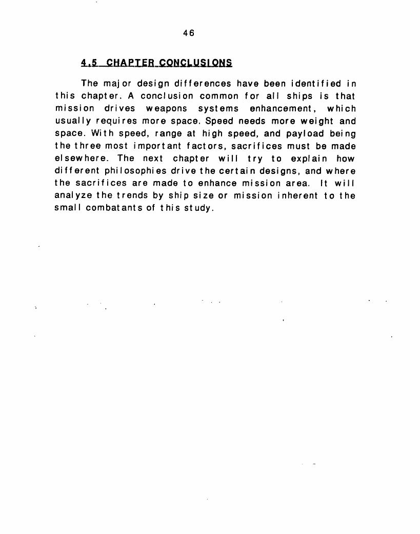
1A. C HAPIERCNCI.UMLQN.
The major design differences have been identified inthis chapter. A conclusion common for all ships is thatmission drives weapons systems enhancement, whichusually requires more space. Speed needs more weight andspace. With speed, range at high speed, and payload beingthe three most important factors, sacrifices must be madeelsewhere. The next chapter will try to explain howdifferent philosophies drive the certain designs, and wherethe sacrifices are made to enhance mission area. It willanalyze the trends by ship size or mission inherent to thesmall combat ants of t his st udy.
47
Fi. 4.1 Weights fraction
II
CPIC SPICA II PHM
SHIPM161 APB 34
Fig. 4.2 Full load weights
241229
105118
72.5
I I I I
I I
CPIC M 161 APB 34 SPICA II PHM
SHIP
120
0-.
0C
100-
80 -
60-
40 -
20-
n-
300
A
200 -
100 -
0
I wiI W2* W30 W4O WS
W6* W7E Loads+margin
. I
II I
I
II
48
Fla. 4.3 Volume allocation
CPIC SPICA II PHM M 161 APB 34
Ship
Fig 4.4 Weather deck sbace utilization
CPIC SPICA II PHM M 161 APB 34
Ship
120
100
80
0 60
40
20
0
- VIV2V3
± V4
120
IIla0I
100
80
60
40
20
0
* Weapons+sensor* Superstructureal Boats/R.A.SO Intakes/Exhaus* Unassigned
49
CHAPTER 5
DESIGN INDICES BY FUNCTIONAL AREA
In this chapter a furtchapter 4 are discussed.hydrofoil, SES) has its every design feature is afiof the country the vesselvessel, and t he mission for
her analysis of the findings ofEach different type (monohull,own characteristics. Likewise,fected by the design philosophywas built for, the size of thewhich the vessel was designed.
Thedivided ar
f unct i onal arease the following:
in which the vessels were
Mobi I it y
St r uct ure
Electrical power
Payload
Command and Surveillance
Ship operat ions
Auxiliaries
Outfit and furnishings
Personnel
50
A1-M. QMLLLIY
Even though effective modern missiles are capable ofbeing launched over-the-horizon, it is necessary to knowwhat is being targeted. To assure that missiles fired willattack high-value units of an opposing force, it may benecessary to close to relatively short range. Thus, tacticswhich take advantage of the speed and maneuverability ofthe small Naval combatants are desirable. Speed andmaneuverability, along with endurance, seakeepi ng, andflexibility of the various designs in the study are includedunder the title of mobility.
The issues of speed, range, seakeeping, and designintegration standards are analyzed in the followingparagraphs, in order to understand how each ,ile of themdrives the philosophy in the design of the different ships.
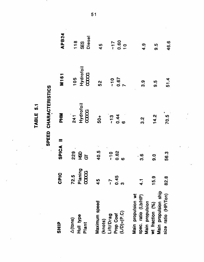
5.1.1 Speed
The speed characteristics of the ships can be found intable 5.1.The fastest ship is M161, and the slowest SPICAII. In SPICA II greater emphasis is given to her anti-submarine warfare role, especially after the maj ormodi f i cat i ons of 1 984. When on ant i - submar i ne oper at i ons,SPICA II does not need to use all its speed, as the sonareffectiveness becomes limited when operating above 25Knots.
Small ships need to be fast as possible, in order to beeffective in their "guerrilla warfare" role, and to protectthemselves against any type of attack, as they lacksophi st i cat ed self - def ense syst ems.
51
a.
o
O
0OI-.amo
a)CYCM Z5
!00 /)
·- a310 c, 0It I O
r-
10 0D,
+ c0 tU) I o
CD 0CI", I c
CD
C L
Cv, NI.
cvCD 0 CeD
cli 1 L
t 2 0c110i Ir O
'a00Q)
E
0E,xco
_
c m
_ ~'Oaca o
u, 24-6 xo - L '-c 4" C)
I O
. _ 0 , O C
C: 0 c: 0 L.
°L °ewe2eV
E)
-
c o
Lcn
Co
0
ot,,
cm
Ao'C) IcriYl C
a) c017 ui C
I" -l co
=
-
52
Speed is affected by different design features. It canbe written as a fraction of:
(Design Budget)x(Hydrodynami c Ef f i c.)Speed.
(Design St andard)
The desi gn budget i s a f unct i on of t he mai n propul si onweight fraction. The hydrodynamic efficiency is a functionof the Propulsive Coefficient and the Lift-to-drag ratio.Finally, the design standard is a function of the mainpropulsion specific weight ratio.
From the above relation we can see that apropulsive coefficient, and Lift to Drag rati'o are inof a speedy ship. Light propulsion components, as wpowerful and light engines drive the speed of a vessel
5.1 .1 .1
largefavor
ell asup.
Hydrodynami c Ef f i ci ency
Hydrodynami cthe production ofpropul si ve coef f i ci
efficiency plays aspeed, and it is
ent and t he lift t o dr
significanta functionag ratio.
5.1 .1 .1a Propul si ve coef f i ci ent
The propulsive coefficient is the ratio betweenpower required to tow the ship at the designed speed,Effective Horsepower, and the power measured inshafting within the ship, the Shaft Horsepower. Thus i
thethethe
t is
role inof the
53
act ually an iinteraction.thus maximi
ndi cat or of t he ef f i ci ency of t he propulsor hIt is desired to have the largest possiblezing the speed for a given Shaft Horsepower.
The propulsive coefficient of all the ships is around0.63 with the exception of the small CPIC and the PHM. PHMuses a single two stage waterjet as a foilborne propulsor,which contributes to a reduction in propulsive coefficientof about 20%. The reduction of the propulsive coefficientof PHM is the trade-off to the reduction of the noiseemitted by the propulsion system.
5.1.1.1b Lift to drag ratio.
Lift to drag ratio (L/D) is actually the ratio betweenthe ship full load displacement and the ship's drag at thespeed the ratio is calculated. For the hydrofoils thepowered dynamic lift, and for the SESs the powered staticlift created by the foils or the lift system.correspondingly, is 'added to the full load displacement,making this ratio rise. Dynamic lift is created in thepl ani ng craft at high speeds, thus raising t heir L/D rat io.
Hydrofoil craft suffer practically no wave makingresistance when foilborne, and since the only *wettedsurface is that of the foils and struts, they have alsofrictional resistance. As a result, for the same totalweight and power they can achieve speeds higher than thecomparable high speed displacement or planing hulls.Before being foilborne, they experience drag both frommai n hull and f rom t he foi I and st r uts, and have a "hump"in the resistance curve, which is taken into consideration,as far as the take-off speed and installed horsepower areconcerned.
lullPC,
54
A fundamental limitation is imposed here by the socalled "square-cube" law, which impacts the growthpotential of hydrofoil ships. Because the lift developed bythe hydrofoil ships is proportional to their wing area (thesquar e of t he I i near di mensi on), i t f ol I ow s t hat as t he si zeis increased the foils tend to outgrow the hull. The sameproblem exists in aircraft, but it is solved by increasingspeed and wing loading as size is increased. Howeverpractical hydrofoil speeds are limited by cavitation.
up onand thtotallower
n t he APB34, a SES, t he cushion of ai r rai ses thethe water, minimizing the contact between thee water. This results i n a subst ant ial decrease i nresistance. As happens with the hydrofoil desdrag permits higher speed for a given power.
shiphul I
theign,
The vertical accel erat i ons, resul tresponse of the SES to wave excitation,i mport ance, si nce t he t he rel at i ve mot i on bof the sidehulls and the water surface wilextent of air l eakage from the cushion.motions will affect t he leakage below the sbow and stern. Whenever air leakage occurssink deeper into the water, thereby resulti
ing from theare of primaryetween the keelI determine theSimilarly, the
eals at both thethe vessel willng in increased
drag of the immersed portions, that is, propulsive drag. Inaddition, the system must make up for some of this loss,and hence there is additional power requirement associatedwith the lift fan operation for this case. There is a trade-off between the extent of immersion necessary to maintainthe cushion and the result i ng propulsive drag fromimmersion, which manifests itself in the case of motion inwaves, as wel as under stat i c perf ormance condit i ons.
CPIC has the lowest lift-to-drag ratio due--to itssmall size.
55
Summarizing, the hydrodynamic efficiency of APB34 ishigher t han t he hydrodynamic ef fici ency of t he ot her shi ps.The hydrofoils and SPICA II have approximately the sameproduct of L/ D and P.C.. The CPIC pays the penalty of itssize, having a hydrodynamic efficiency around 3.
5.1.1.2 Mai n Propul si on Weight Speci f i c Rat i o
The main propulsion weight specific ratio is ameasure of the overall weight to propulsion powerefficiency of the propulsion plant. A lower ratio indicatesthat the plant will provide more power for a givenpropulsion plant weight, which may allow for an increasein ship speed w i t hout an appreciable effect indisplacement, or may allow for a decrease in the physicalsize of the plant.
The small combatants of the study have advancedtechnology propulsion plants in order to save.weight. Fort his reason t he sm'all vessels having extremely lightweightplants, have significantly lower W2/SHP ratio than otherbigger ships, which need more flexible and ruggedpropulsion plants to fulfil their longer missions. Theweight saved in the plant allows higher speed and at thesame time an increased proportion in the weight fractionsof the other vital ship areas.
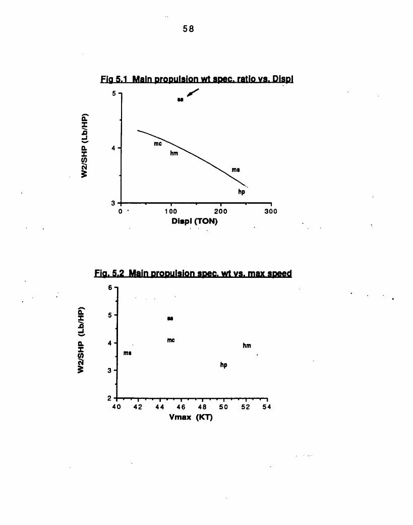
The sel ect i on of Di esels as propulsion engi nes for theAPB34 drives the main propulsion weight specific ratio up(see figures 5.1, and 5.2), since the diesels are heavierthan gas turbines for the same delivered power. So, theeffect of the large main propulsion weight specific ratio,of APB34 neutralizes the advantage of the high propulsiveefficiency, making the ratio of the propulsive efficiency
56
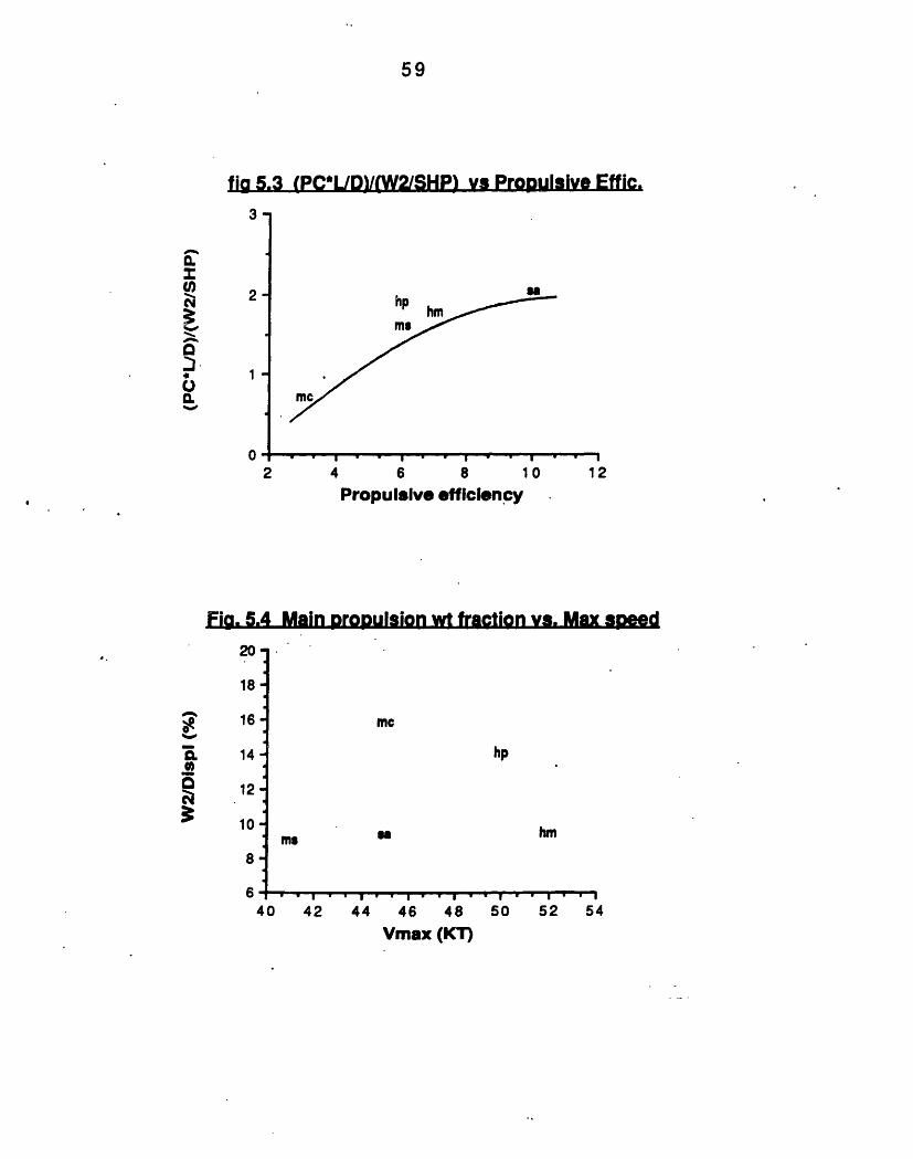
over W2/SHP similar to that of the other ships, as can beseen in figure 5.3.
PHM has a very low main propulsion weight specificrat i o, necessitated by the trade-off of the lowerpropulsive efficiency, due to its lower propulsi vecoef f i ci ent . Thi s t rade- of f i s apparent i n t he ot her desi gnsas well, as can be seen from figure.5.3. Excluding theinefficient smal I CPIC all the ot her ships haveapproxi mat el y t he same rat i o of Propulsive Efficiency overmai n propulsion weight speci f i c rat i o, living theachi evement of a higher speed t o t he desi gn budget.
5.1.1.3 Design Budget
For a certain ship, t he higher design budget is i n favorof a higher speed.
The design budget versus speed relation can be seen infigure 5.4. The CPIC has the highest ratio due to its heavytransmission system for its size. Although PHM has only aGas Turbine for propulsion and a light transmission, thewater used for the foilborne or hullborne waterjets, andthe two diesels used for hullborne propulsion drive theW2/ D rat i o up. The ot her three ships have a mai n propulsionweight fract ion constant around 9.5.
5.1 .1.4 Conclusions
The discussion of t he previous paragraphs indicate t hehigh cost of CODOG plants and Diesel Propulsion. Due to theneutralization of high propulsive efficiencies from highmain propulsion specific ratios, the most important indice,

57
as far as speed is concerned is the main propulsion weightfraction. So speed costs, as we need a higher W2/ A toachieve a higher speed.
58
Fia 5.1 Main DropUlsion wt spec. ratio vs. DispI
0 '
4-
3
SI
mc
hm
ms
hp
0 100 200Dispi (TON)
300
Fig. 5.2 Main propulsion spe. wt vs. max speed
UN
mwhm
hp
Vmax (KT)
.0-J0.
V)
N
Q.
-I%Cw
5-
4-
3-
ms
240 42 44 46 48 50 52 54
_
_ . . . . . . . . . , . . . . . . . . .
P
A
. . I . I . I . . . . . . .
59
fiag 5.3 (PC*L/D)/(W2/SHP) vs Propulsive Effic.
2-
1-
02
hp
Ms1
4
Jml
hm
6 8 10 ' 12
Propulsive efficiency
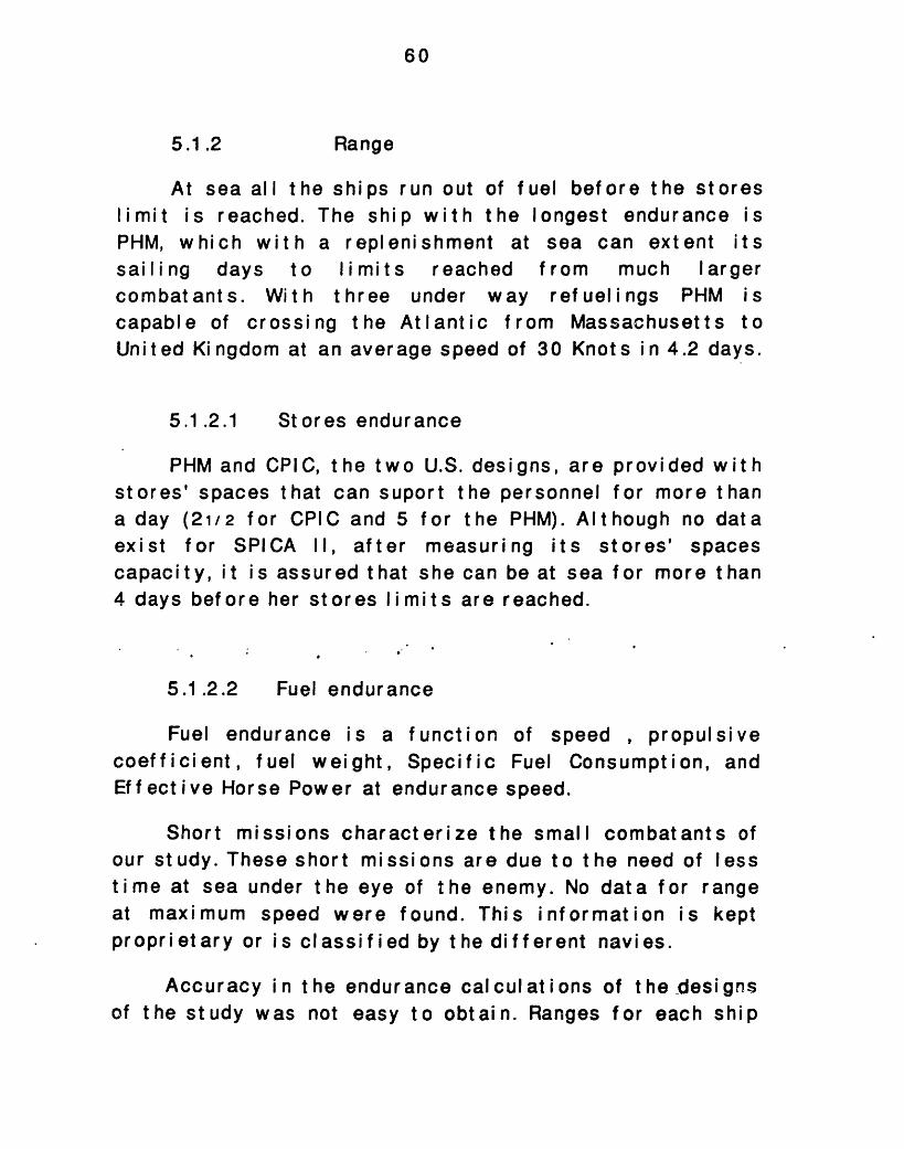
Fig. 5.4 Main proDulsion wt fraction vs. Max speed
Za.
18
16
14
12 -
10
8-
640
mc
hp
msma
_I I m _ _ _* I x,,,,,, .I ... *
42 44 46 48 50
Vmax (KT)
hm
I. ' I52 54
zS0-au,cu4x0
CI.
a=1·U0.%-
v
-30I.,'a
I _ I ~ - -I I ....
3 I
I
60
5.1.2 Range
At sea all the ships run out of fuel before the storeslimit is reached. The ship with the longest endurance isPHM, which with a replenishment at sea can extent itssailing days to limits reached from much largercombat ants. With three under way refuelings PHM iscapable of crossing the Atlantic from Massachusetts toUnited Kingdom at an average speed of 30 Knots in 4.2 days.
5.1.2.1 Stores endurance
PHM and CPIC, the two U.S. designs, are provided withstores' spaces that can suport the personnel for more thana day (21/2 for CPIC and 5 for the PHM). Although no dataexist for SPICA II, after measuring its stores' spacescapacity, it is assured that she can be at sea for more than4 days before her stores limits are reached.
5.1.2.2 Fuel endurance
Fuel endurance is a functioncoefficient, fuel weight, SpecificEf f ect i ve Horse Power at endurance
of speed , propulFuel Consumption,
speed.
Short missions characterize the smallour study. These short missions are due to ttime at sea under the eye of the enemy. Noat maximum speed were found. This inforproprietary or is classified by the different
combat anthe need ofdata for r;
mation isnavi es.
si veand
s oflessangekept
Accuracy i n t he endurance calculat ions of t he designsof the study was not easy to obtain. Ranges for each ship
61
can be found on Table 4.1 for a speed around 16 Knots. Therange of M161 at 16 knots could not be estimated, but isseems t hat it is smaller than that appeari ng i n table 4.1 at42 knots, due to the high SFC of the Gas Turbines in slowspeeds, and the large drag as at the speed of 16 knots, asat t hi s speed M161 is operat i ng hull borne.
Fuel endurance may be found from the followingrelationship:
(V)X(P.C.)X(WFUEL) 1
R- . -Cx(L/ D)x(WF/ D) x(SFC) x(EHP) (SFC)
Where C i s a conversi on f act qr.
So Range could be writt en as:
R( Desi gn Budget )x(Hydrodyn. Ef f i c.)x(Desi gn Ef f i c.)
The small L/D ratio of CPIC as well as its small sizeand its small installed SHP make its fuel 'endurance the.smal I est of all t he ot her shi ps.
There is always a trade-off between payload weightand the weight of the fuel a vessel can carry (its designbudget), and thus its range. For example the fuel weight,M161 can carry ranges from 16 to 21 tons, thus extendingits range from 750 to 1150 Nm., depending on its missionand the amount of crew aboard (4- 1 5).
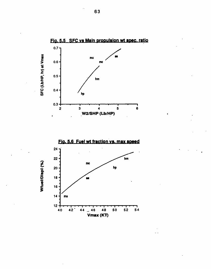
Ships with higher main propulsion weight specificratios, tend to have higher SFCs at maximum speed, as canbe seen from figure 5.5. This is due to the upward trend of
62
the Specific Fuel Consumption at maximumW2/SHPB is increased. There is also a misconcerning the fuel weight that can be carriedships. (See figure 5.6). The more speedy thehigher t he f uel wei ght f ract i on.
speedsion treaboard tship, t
5.1.2.3 Concl usi ons
Design budget of fuel weight is the most importantmet hod t o get a longer range. Range and mission I engt h arecri t i cal to fuel cost. Efficient design standards andhydrodynamic efficiency also play an important role.Finally, it can be assumed that stores endurance does notnormally limit the ships operation, as every ship reachesthe fuel limit first.
asndhehe
,
63
Fia. 5.5 SFC vs Main propulsion wt sPec. ratio
m me0.6-
0.5-
0.4 -
2 3 4 5 6
W2/SHP (Lb/HP)
Fig. 5.6 Fuel wt fraction vs. max speed
I I .
Z4
22--
20 20
a 18-
16-
14
12*4
hm
mehp
u
ms
0 42' 44, 46 48Vmax (KT)
50 52 54
0.7-
xI
a-1
0lI.U,
0.3;·II
. . . . . . . . . . . . . .
l
lip
A,
. . I I , I I
64
5.1.3 Seakeepi ng
The seaworthiness of a hull form is related to threef actors: The wave response character i st i cs of t he shi p, thenature of the wave environment, and the ship's speed andheadi ng.
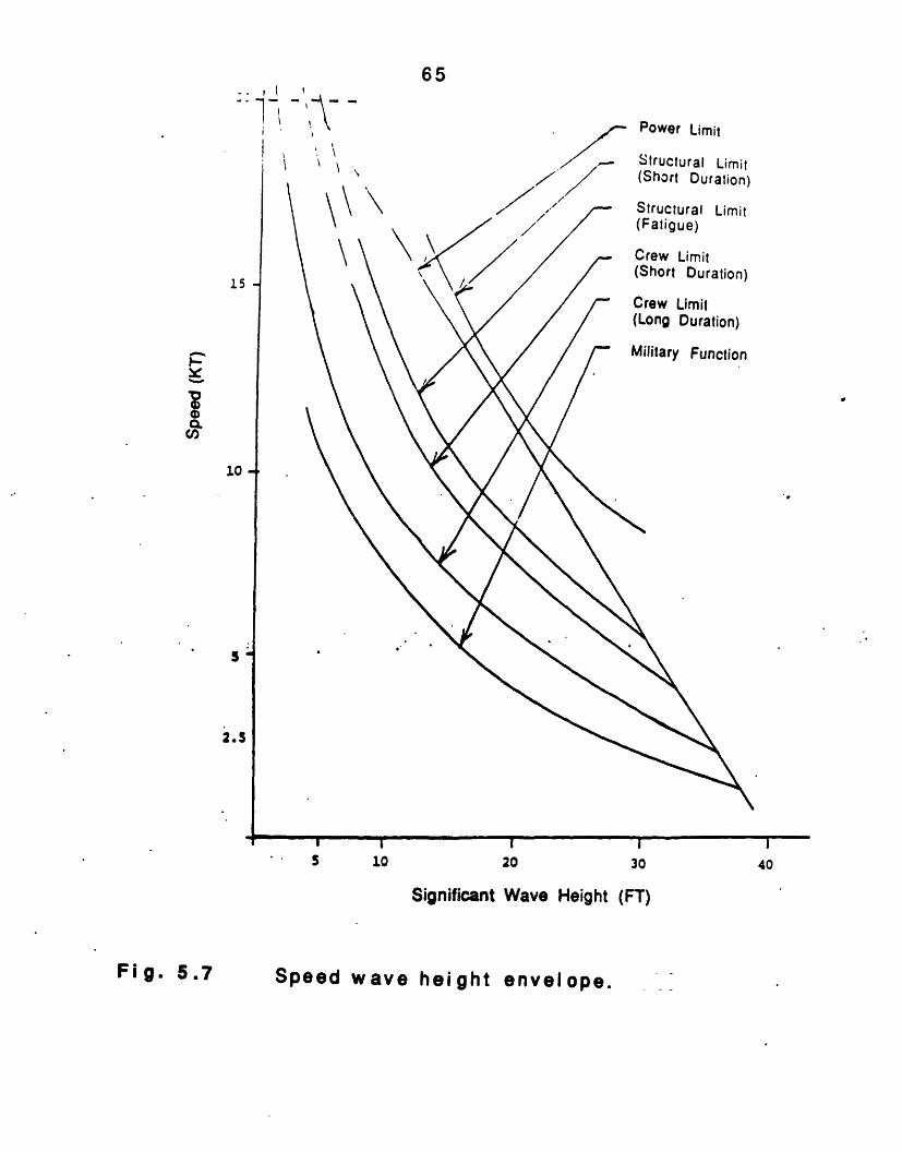
The limiting factors for heavy seas are militaryperformance, crew performance, structural load limit andpowering limit. Figure 5.7 shows this speed-wave envelopefor a typical military vessel. It can be seen that shipsslow down first due to the degradation of militaryeffectiveness.ln the following pages the factors thatenhance ship performance and maneuverability in calm andheavy seas are i nt roduced.
For small combat ant s, t his the speed the ship can susevere slamming and deck influence on t he seakeeping ais its size as characterized Ithe slenderness ratio (L/ V/3).more is considered sufficientII and CPIC have a slendericorrespondingly. CPIC and SPI4of about 400 to reduce pitchVee aft to the transom of slamming and heave.
a f i nal measure of seakeepi ngstain in rough seas withoutfetting. The greatest singlebility of a conventional shipby its length, and especially· A slenderness ratio of 7 or
to counter slamming. SPICAness ratios of 7.2 and 7.3CA II use a deep Vee forwardand heave. CPIC uses also aabout 120 to further reduce
Power Limit
30
(FT)
40
Speed wave height envelope.
I,
1 _
65
15
-
covn
10
2.5
S 10 20
Significant Wave Height
II
I"I
Fi g. 5.7
66
The use of the lifting surfaces on PHM and M1 61 reducesthe effect of waves on these ships. The reaction of thesesurface piercing hydrofoils to waves is substantially lessthan for the high-speed displacement SPICA II or theplani ng hull of CPIC. But t he requi rement f or shi p mot i on tobalance t he di st urbi ng forces caused by t he waves, coupl edwith geometric limits to a practical design, restricts thesea states in which high speed operation can be consideredacceptable. For this reason, PHM and M161 augment theirstability by the mutual interworking of the submergedfoils with the ship's automatic control systems (ACS). TheACS provides continuous dynamic control of the shipsduring take-off, landing, and all foilborne operation. Inaddition to providing the ship's roll and pitch stability, theACS controls the height above the water surface, causesbanking in turns and eliminates ship motions caused byorbital particle motion of the waves. The ship hulloperates above the effect of the surface waves. The foilsthat provide lift and control forces operate below thewater surface where wave effects diminish with depth.Foilborne operations only become limited as the waveheights exceed the hydrofoil strut length. The result is anexceptionally smooth operating environment for crew andcombat syst ems equi pment. Less well real i zed i s t he maj orcontribution of the foil systems to motion reduction whenhullborne. The foils act as dampers which significantlyreduce mot ions i n both t he roll and pitch modes.
Figure 5.8 shows the reduction of ships' speed as afunction of the significant wave height. These data clearlyshow the ability of the hydrofoil ships to maintain speedsover 40 knots in rough seas.
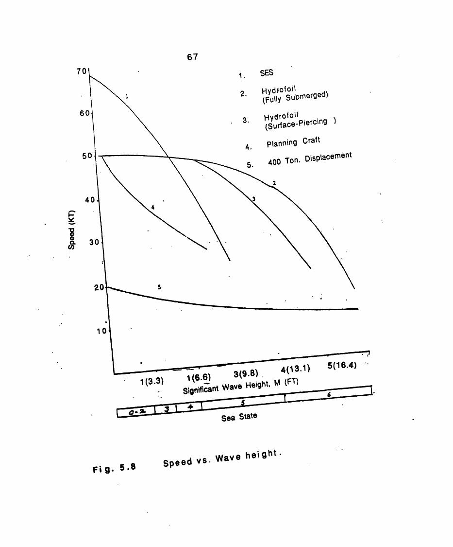
67
5
pI0cren
1(3.3) 1 tt5.) . (FT)
Significant Wave Height, M (FT)
Sea State
a .I8' Speed vs. Wave heightrli. ' '-
68
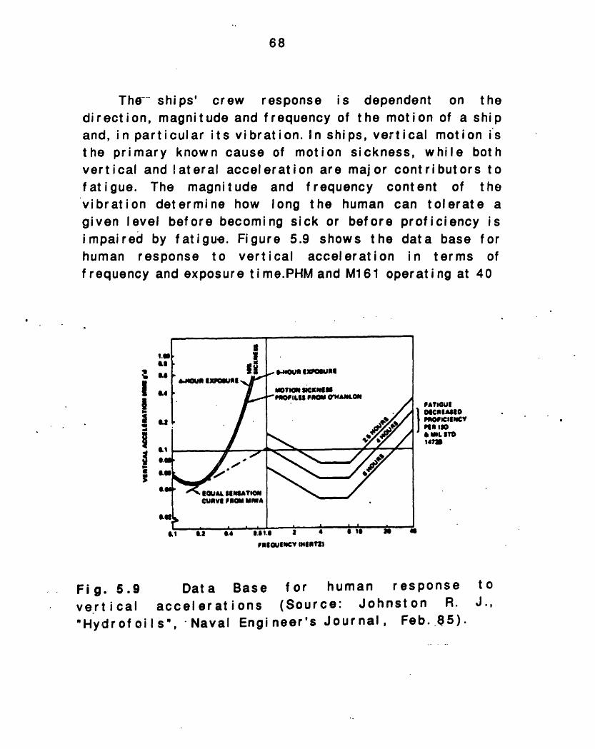
The-- ships' crew response is dependent on thedirection, magnitude and frequency of the motion of a shipand, in particular its vibration. In ships, vertical motion isthe primary known cause of motion sickness, while bothvertical and lateral acceleration are major contributors tofatigue. The magnitude and frequency content of thevibration determine how long the human can tolerate agiven level before becoming sick or before proficiency isimpaired by fatigue. Figure 5.9 shows the data base forhuman response to vertical acceleration in terms offrequency and exposure time.PHM and M161 operating at 40
II,g
*~ A I .
Il -SPATlOllCURVI PriOM Mia
mvtON ScaKNeIIMOILU FROM @ANLON
~~~~~~~j~~~4~
I 0.8 as .4 6.51.. 1 *OInmISuCfI af nIUI
Fig. 5.9vert i cal"Hydrof oi
Data Baseaccelerations
Is", Naval Engi
for(Sour
neer's
humance: JohiJournal,
responsenston R.
Feb. _85).
1.iLS..
W
&.e0.Ugam
I
II3II
amU
PAt1OU!INCIBIOAPOIOZINCYP 1, 0
I..L MT.14?U
.Is 31 44
toJ.,
[ . . · . - · ·! i I
,
69
knots in head seas will encounter waves every 1 to 2seconds depending on wave period.
The commander of a conventional ship, unwilling tosubject his ship or his crew to punishment of the roughseas, will slow down to the "good practice" limit of oneslam per minute (0.017 Hz), a wave encounter frequencybelow the data base.
In order to reduce rolling CPIC uses a hard chine, Veesforward and aft, and transom fin stabilization.
SPICA II has a deep keel, a semi hard chine, and a deepVee forward.
The APB34 does not have a sharply pointed slenderbow and a deep draft commensurate with its size. Instead,it is supported on an air cushion which reduces draft,lowers overall resistance and ship motions, and increasesperf or mance.
The cushion height is determined by the desire to haveit exceed the majority of waves encountered in theproposed operating environment and to satisfy transversestability considerations.
APB's plenum under the hull serves as a passivemotion-damping accumulator that significantly reducesmotions i n large seas.
When APB34 is operating in the hullborne mode, itt ends t o have approxi mat el y t he same f reeboard as si mi I arsi zed monohul I s. However, when on cushion, f reeboardincreases dramatically by a factor of 2. On cushion, thewetdeck is sufficiently high to greatly reduce thestructural bending moments and permit high speedoperations in high seas without slamming. This high on-
70
cushion freeboard also provides safe dry decks in high seast at es.
In the CPIC deck wetness is mitigated bydouble hard chines which reduce spray. SPICA IIand spray chines.
t he use ofuses flare
When operating on cushion, the lift system withactive ride control provides a very good ride whencompared to a monohull of equivalent size. Typically, asverified by model test and full scale trials, SESs do notexper i ence hull sl ammi ng unt i I t he si gni f i cant wave hei ghtexceeds the wetdeck height. The physical reason for thiscapability is that, unlike a monohull or hydrofoil whichrides about t he mean draft at about the middle depth of thehull, strut, or foils, an SES operates with the meanwaterline close to the keel. This provides significantlymore freeboard and clearance than an equivalent sizemonohull displacement ship. The SES pneumatic ridecontrol system operates effectively at all speeds andheadings in either a plat f orming or contouring rnode.
This seakeeping, when combined with the low pitch,roll, and heave motions of an SES (which are typically 1/2to 1/3 of- those of an equivalent monohull), make SESsattractive candidates for missions that require operationin areas where sea states 5 or 6 occur significantpercent age of t he ti me.
The vertical plane mot ions of heave and pitch forAPB34 are influenced primarily by waves. The motions arenot the only aspect to be considered, but also the verticalaccelerations. These vertical accelerations affect thebasic ride quality, which has a significant influence on theperformance of various subsystems on the craft. Likewise,t he vert i cal accel erat i ons i n hi gher f requency range caused
71
by high speed can be irritating if not adequately regulated.The current generation control systems attempt tomaintain constant cushion pressure and are very successfulat it. However, the contributions to accelerations such ashydrodynamic sidehull and seal forces together with theimpact of very long ocean swells are not currentlycontrolled, and an improvement of control systems isneeded.
5.1.3.1 Maneuverabi I it y
Besides themore maneuvconventional
signif i
erabl eships.
cantandFoil
speedprovideborne t
advantage, hydrofoilsmore stable platform
urns are accomplishedin a bankedcent rif ugal fpredominantlysubmerged foifrom .the suenhances crewaccel er at i onsgreater vertiTherefore hydrdegrees per
(coordinated) fashion. Thisorce requi red in turns to
by the reliable lift capabiI rather than the unpredictablerface- piercing' struts. Turncomfort during high-rate turns
due to turning are felt primaril,cal forces rather than lat of oil ships have design turn rat second, two to four time,
causes thebe providedlity of theside forces
coordi nat i onbecause the
y as lightlyeral forces.Bs of 6 to 12s those of
conventional ships, and they can maintain these rates inboth calm and rough seas. This makes the hydrofoil ship amore difficult target for enemy missiles, guns, andtorpedoes. But in order to obtain this outstanding roughwater behavior, the construction budget of the hydrofoil isincreased due to the need of the foil system with itsrelatively compl ex st rut, f oi Iand f I ap structures,automatic control systems and high power -hydraulicact uat i on systems.
arethan
72
5.1.3.2 Conclusions
More information is needed in order to accomplish adetailed seakeeping or maneuverability analysis, for thevessels of our study. Roll, heave, pitch periods are needed,as well as maj or other parameters as accelerationresponses, power spectrums etc.
Hydrofoils have themaneuverability of all thedisadvantage of irritatingf requenci es. (Ref erence 40)
best seakeeping capability andships. SESs come next, with thevertical accelerations at high
73
5.1 .4 Propulsion System Design Integration
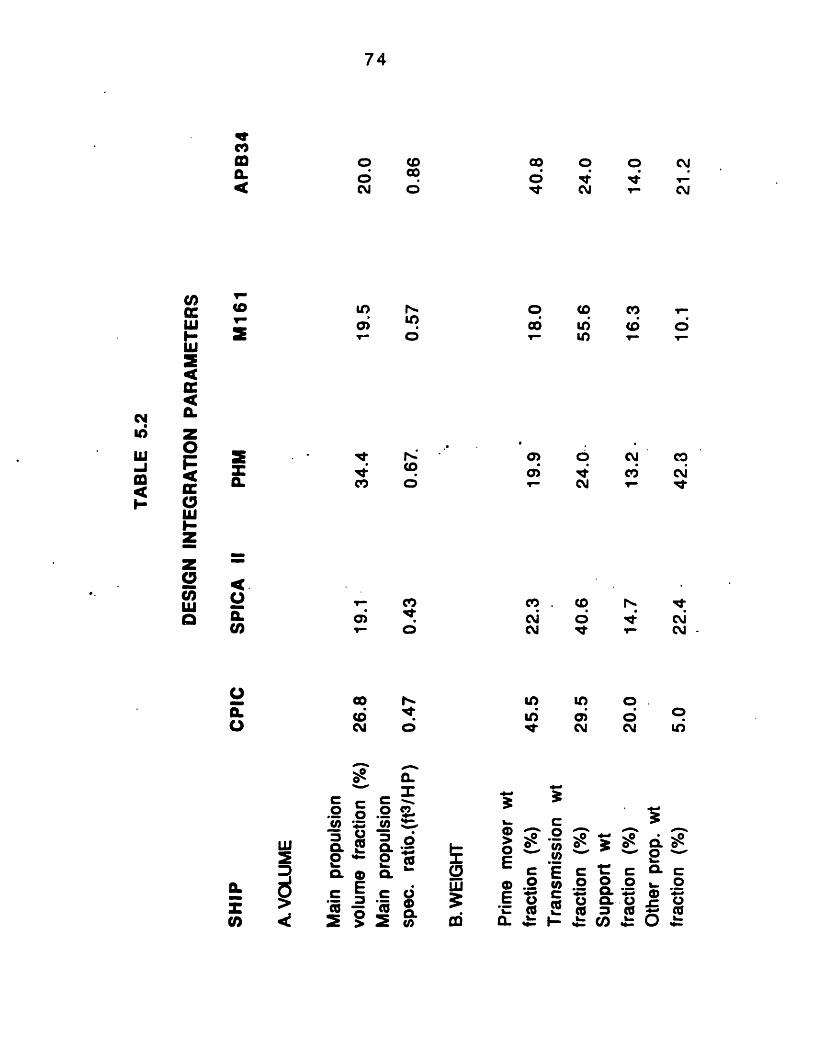
The maj or elements of a ship's propulsion system arethe prime mover, the transmission and the propulsor.Critical factors affecting the selection of the propulsionsystem include top and cruise speeds, ship size, range andendurance, hul I geomet r y, engine mat chi ng, draf t,vulnerability and maneuverability. For high-performanceships sufficient power must be available to permit the shipto traverse the hump and achieve design speed. To establishinstalled power and fuel requirements for specifiedperformance levels, it is necessary to estimate thei ndi vidual eff iciencies of t he elements.
After knowing the power and the efficiencies of thevarious propulsion elements, thei r i ntegrat ion is needed i norder for the designer to be able to install them on theship. The way engines and other propulsion components areselected, and located within the ship affects all otherships characteristics. Once speed and size have beenestablished, the propulsion system weight and volumerequirements can be delineated. But space, volume andweight devoted to propulsion takes away from other vitalship functions. Thus, propulsion plant integration isiterative in nature.
The following pages present why different propulsionsystems are selected for each ship, and discuss how thisselection is driving weight and volume allocations as wellas propulsion operability and survivability.
The propulsion systems characteristics of the vesselsof the st udy can be found on table 5.2.
c0 0 0 CNT". . .
o o C _a, U) (D 0VI Un _r _L
o) 0 cO_- CY Nb
c . co
CM ,
coCU
4 CNr q -
I) U)O .
Ii. 0 0c,~- Nd o
oui
o-
c
a *2 Q 1
a . c E
co4
0.c Ic ,§..
a75 co
*Y )
3 3. C
0 CA
CL %EI. n . u0. *,(0 m e~c
74
mC'
rl
=E-(0
o (GCM 0
r OC O
CN C ,,
r 0
N
m-J
en
(nc:WI-
CWI-
z0Cc
aC/)IAIa
CL
C)Ua
OC)CE,
(Q O
C6CY0
V
P _Q. PQ c~'CO
O ',
C tr c000a cxf_ a'- C) &-t;g00-C.)~
75
CD CD * C co d
0) 0 U)0, v un cn_ oa) io u - _
CN oP1 b S 0cr
C C CcD c NIn Ul 0
)t cO CD 00 0
CL
I 0 00c c _t .0om o a.0 a
U) ~-U CL i5 I
C'.-ar~~11 X00 .2° 2 c 2
*Xt X, (a @ ,, D
caC0
4- -h._̂
_ xt . 0o CQL XCCc 0* F
C)
U)
Dco
u)N~ co
0 C0
owc~C1
N~
0)U)
C,
V.
C.'
n --D
Q >C (W
m '
76
The Brake Horse Power (BHP) is of prime interest since itdictates--the propulsion engine selection. The BHP is givenby'
(Tn)x(V)BHP, -
550x(PC)x(nT)
Where Tn is the net propulsor thrust (after accountingfor propulsor mounting and ship interaction losses), V ist he shi p's speed, PC t he propul si ve coef f i ci ent, and nT t hetransmission efficiency.
From examination of figure 5.10, it can be seen thatless propulsor thrust is needed by the hydrQfoils and theAPB34, i n order to achieve t heir maximum speeds comparedto monohulls of the same size. PHM for example achieves40 Knots using 11,000 SHP while SPICA II, a monohull ofthe same displacement, uses 12,900 SHP.
5.1 .4.1 Pri me Movers
APB34 uses two diesels at 5,500 SHP as primemovers. All the other ships are driven by gas turbines. CPICuses three gas turbines at 6,000 SHP, SPICA II three at12,900, PHM one at 17,000 SHP, and M161 one at 5,400 SHP.
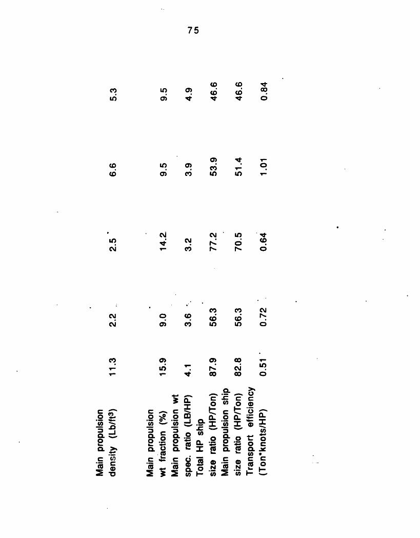
The weight of the propulsion plant itself is a crucialconsideration in the design of a vessel, since higherpropul si on plant wei ght f ract i on f avors speed. But as speedincreases and of course becomes costly, weight is deprivedfrom all the other ship functions. The measure of thepropulsion plant weight efficiency is the main -propulsionweight specific ratio in pounds per SHP. The Diesel-
77
powered APB34 derives less power from the amount ofweight used for the propulsion plant, than the other ships(see figure 5.1). All the other vessels having gas turbinesas prime movers, have lower specific weights. The lowestis that of PHM with the LM2500 driving the 241-tonhydrofoil at a speed in excess of 50 Knots.
As the fuel weight is a very significant considerationin the ship design, the power plant must have a low SFC tomi ni mi ze t he f uel wei ght carri ed on board. SFC ref I ect s t he
operational ef f i ci ency of the ship's pow er pl ant. Itsdetermination is basic to accurate estimation of the fuelrequired for operation in various sea states and atdifferent ranges. The SFC of Marine engines varies withengine revolution per minute (RPM), and power level. TheSFC of the ships of the study varies between 0.38 and 0.64(Pounds per HP-hr), at maximum speed. The LM2500 of PHMhas the bestof APB34 the
operat i
higheronalSFC.
efficiency, while the MTU Diesels
.The association bet ween SFCweight specific ratio can be found idata base is needed to determine ifbetw een SFC and W2/ SHP.
and inai nn figure 5
t here exi
piopul si on.5. A larger
sts a trend
5.1 .4.2 Transmissions
For small FPBs the selection of the light weighttransmission systems is of prime importance. Of secondaryimportance are high efficiency, flexibility, reliability(which is related to higher weight), and simplicity. Otherdesirable characteristics include maintainability, lowvol ume, and low noise levels.
78
APB34 and the two monohulls drive their propellerst hrough rel i abl e V- Dr i ve t ransmi ssi on syst ems. The di esel -driven APB34 has a small transmission weight fraction(20%). SPICA II, with its higher-rated Gas turbines uses alarge proportion of weight, 41%, for its transmissionsyst em, due t o t he need to handle hi gher engi ne power t hanthe other three ships. CPIC allocates the 29.5% of itspropulsion weight for power transmission. M161 has a V-Drive transmission and a Z-Drive to transfer the mainengi ne power to t he propeller, and its transmission weightfraction is the largest of all five vessels (55.5%). PHM hastwo small sets of reduction gears to drive its waterjet,and only 24% oftransmission.
its propulsion weight is allocated
Propulsors
M161 uses a four-bladed controllin order to fulfill the requirement ofcoef f i ci ent due t o t he resi st ance of t hand the variation of resistance due toI oadi ng condi t i ons
SPICA II, CPIC, and APB34 usepropellers. Supercavitating propelleroperate acceptably in the high-speedwit h a ful ly developed blade cavity.
able-pitch propellervariation in advancee ship at hump speedthe environment and
supercavitating CRP's are designed to
range by operating
Thethe openi nvol ved.range ofsupercavitake- off .
waterj et propulsor of PHM is morepropeller due to the greater numberIt has also lower propulsive effi4
50 Knots as compared to fullitating propellers, and relatively I
But by the use of the waterj et
complex thanof componentsciency in thely submergedow thrust atthe designer
5.1 .4.3
for
79
avoids complex transmission systems, such as the Z-Driveconfiguration.
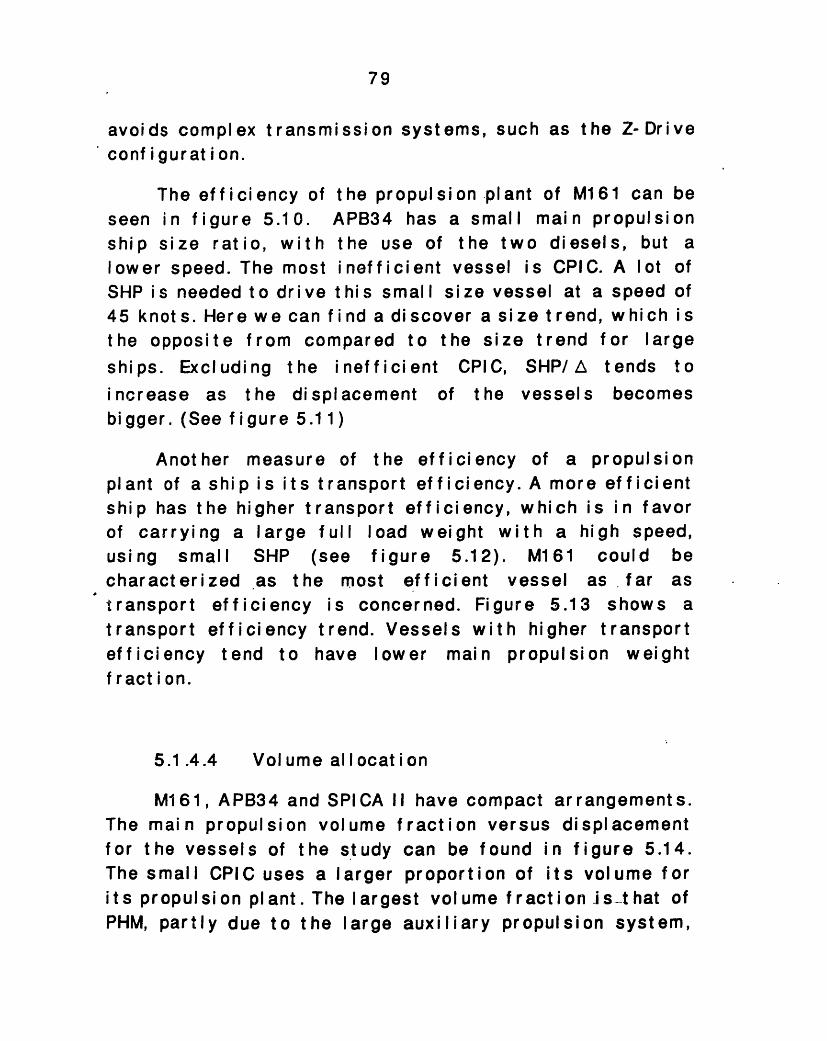
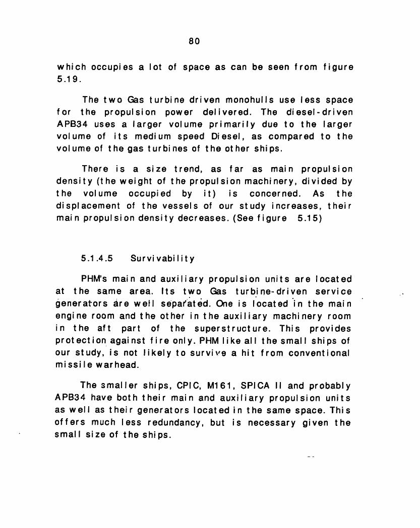
The efficiency of the propulsion plant of M161 can beseen in figure 5.10. APB34 has a small main propulsionship size ratio, with the use of the two diesels, but alower speed. The most inefficient vessel is CPIC. A lot ofSHP is needed to drive this small size vessel at a speed of45 knot s. Here w e can f i nd a di scover a si ze t rend, w hi ch i sthe opposite from compared to the size trend for largeships. Excluding the inefficient CPIC, SHP/ A tends toincrease as the displacement of the vessels becomesbigger. (See f i gure 5.1 1 )
Another measure of the efficiency of a propulsionplant of a shi p i s i t s t ransport ef f i ci ency. A more ef f i ci entship has the higher transport efficiency, which is in favorof carrying a large full load weight with a high speed,using small SHP (see figure 5.12). M161 could becharacterized as the most ef f i ci ent vessel as far astransport efficiency is concerned. Figure 5.13 shows atransport efficiency trend. Vessels with higher transportefficiency tend to have lower main propulsion weightfraction.
5.1 .4.4 Vol ume al I ocat i on
M161, APB34 and SPICA II have compact arrangements.The main propulsion volume fraction versus displacementfor the vessels of the study can be found in figure 5.14.The small CPIC uses a larger proportion of its volume forits propulsion plant. The largest volume fraction is_that ofPHM, partly due to the large auxiliary propulsion system,
80
which occupies a lot of space as can be seen from figure5.19.
Thefor theAPB34 usvol ume ovolume of
densthedi splmai n
two Gas turbine driven monohulls use lesspropulsion power delivered. The diesel-;es a larger volume primarily due to thef its medium speed Diesel, as compared
t he gas t ur bi nes of t he ot her shi ps.
There isity (the vol ume
IacementI propulsi
spacedrivenlargerto the
a size trend, as far as main propulsionveight of the propulsion machinery, divided byoccupied by it) is concerned. As theof the vessels of our study increases, theiron density decreases. (See figure 5.15)
5.1.4.5 Survivability
PHM's main and auxiliary propulsion units are locatedat the same area. Its two Gas turbine-driven servicegenerators are well separ'ated. One is located in the mainengine room and the other in the auxiliary machinery roomin the aft part of the superstructure. This providesprot ect i on agai nst f i re only. PHM I i ke all t he small shi ps ofour study, is not likely to survive a hit from conventionalmissile warhead.
The smaller ships, CPIC, M161, SPICA II and probablyAPB34 have both their main and auxiliary propulsion unitsas well as their generators located in the same space. Thisoffers much less redundancy, but is necessary given thesmall size of the ships.
81
5.1.4.6 Operabi I ity
All the ships of the study are difficult to repair atsea. Due to their short mission, they are designed with thephilosophy of repair at home port. Only small space isprovided for the crew to perform any major repair work atsea. As can be seen from figures 5.16 through 5.19, themachinery components of the ships are packed into a smallarea. It i s i mport ant t o save space f or ot her shi p f unct i ons.
5.1 .4.8 Conclusions
Space and weight are two very critical factors for thesmall ships of our study. High speed needs designefficiency and a lot of power. But t he requirement to put asmuch power into as small a space as possible runs counterto the ease of maintainance, survivability and ruggedness.
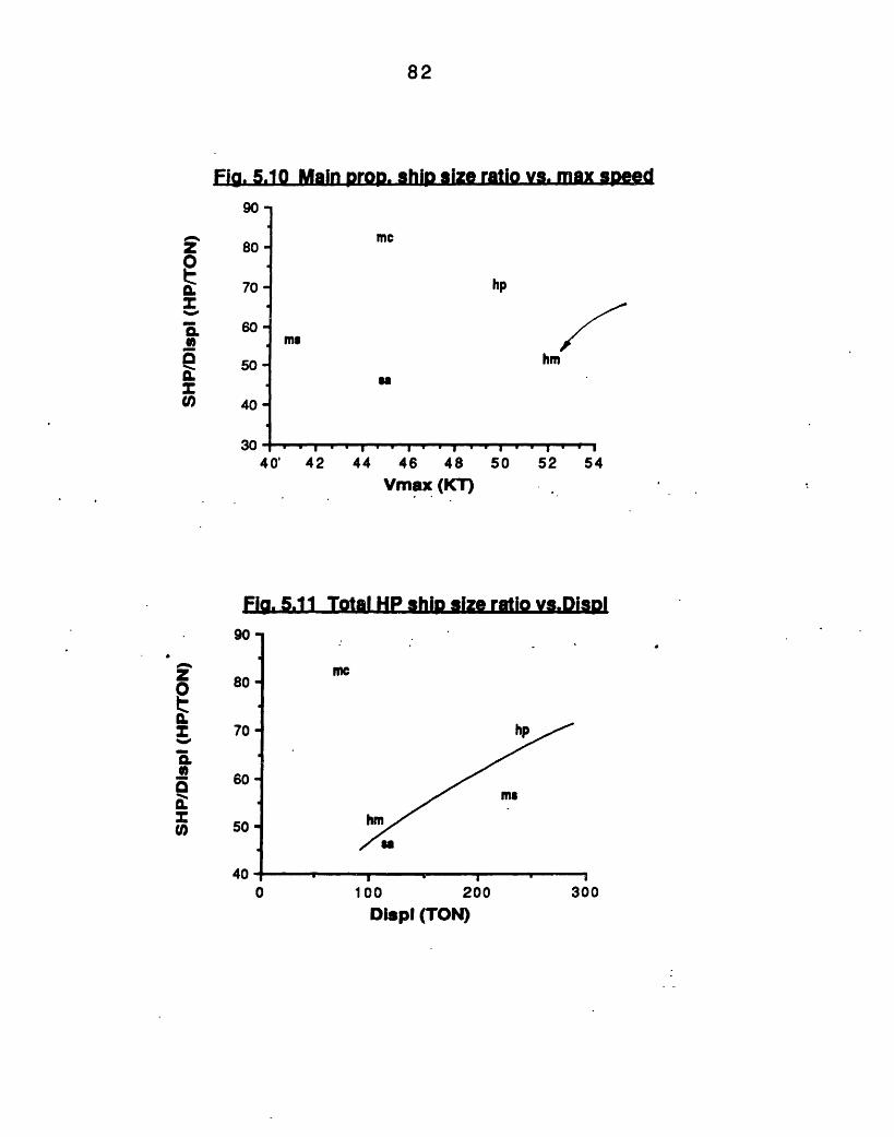
82
Fig. 5.10 Main Drop. ship size ratio vs. max speed
90
80
70
60
50
40
30
me
hp
me
SI
40' 42 44 46 48 50 52 54Vmax (KT)
Fla. 5.11 Total HP ship size ratio vs.Displ
me
hp
me
hm
's
100I2O 30
200 300Displ (TON)
0
n
0
a:
U,
80
70-
0
zm
n_
60
50
400
Y ..
I II
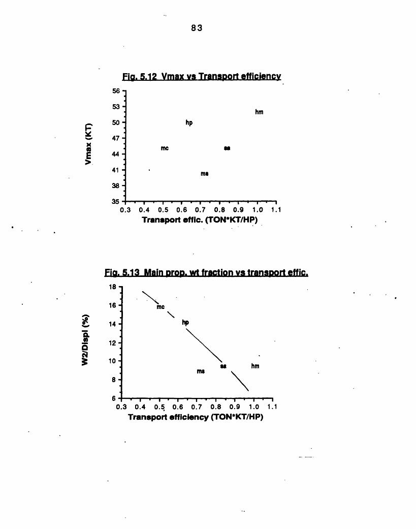
83
Fia. 5.12 Vmax vs Transport efficiency56 -
53-
50-
47
44-
41 -
38-
03 ;
hm
hp
me a
ms
-. I . I . I . I I . I . I
0.3 0.4 0.5 0.6 0.7 0.8 0.9 1.0Transport effic. (TON*KT/HP)
1.11.1
Fi. 5.13 Main DroD. wt fraction vs transDort effic.
0.3 0.4 0.5Transport
hp
mehm
I ' I ' I . I ' I '0.6 0.7 0.8 0.9 1.0
efflciency (TON*KT/HP)
IEE
18-
16 -
14
mc
F0
3=1
12
10
8-
A I I
1.11. 1
I I ! !
I
IN I
vW · I I
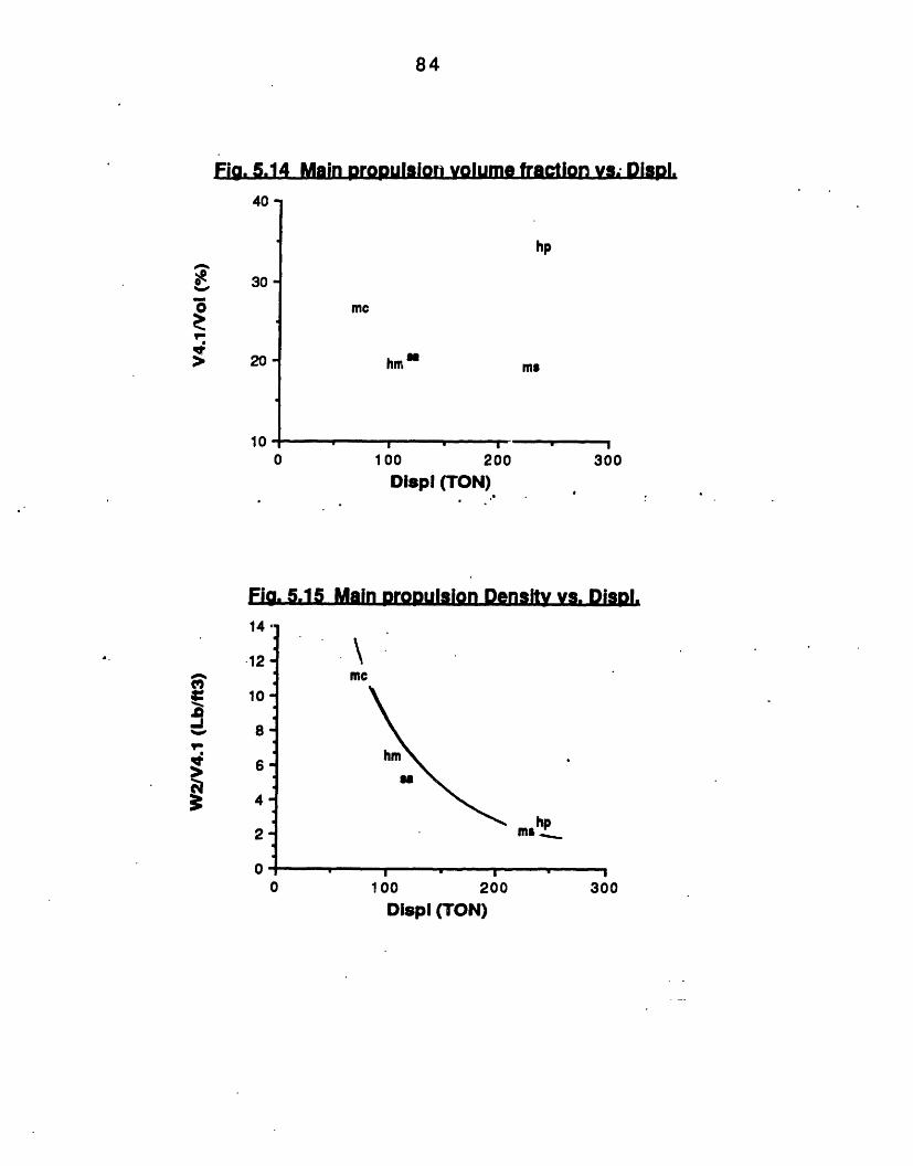
84
Fig. 5.14 Main oropulsion volume fraction va; DiaI.40-
30
20
10
hp
me
hmm
0 100
Displ (TON)
ms
200 300
Fig. 5.15 Main propulsion Density vs. DisDI.
me
hmN
mI
hp
I00
100 200 300Dlspl (TON)
.5AV
'I09
0
IJ%.
In
c
14
12
10
8-
6
4
2-
u0
I - - _- _ I .
-
J~
I
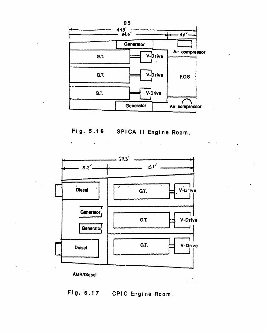
85
Fig. 5.16 SPICA II Engine Room.
AMR/Diesel
CPIC EngineFig. 5.177 Room.
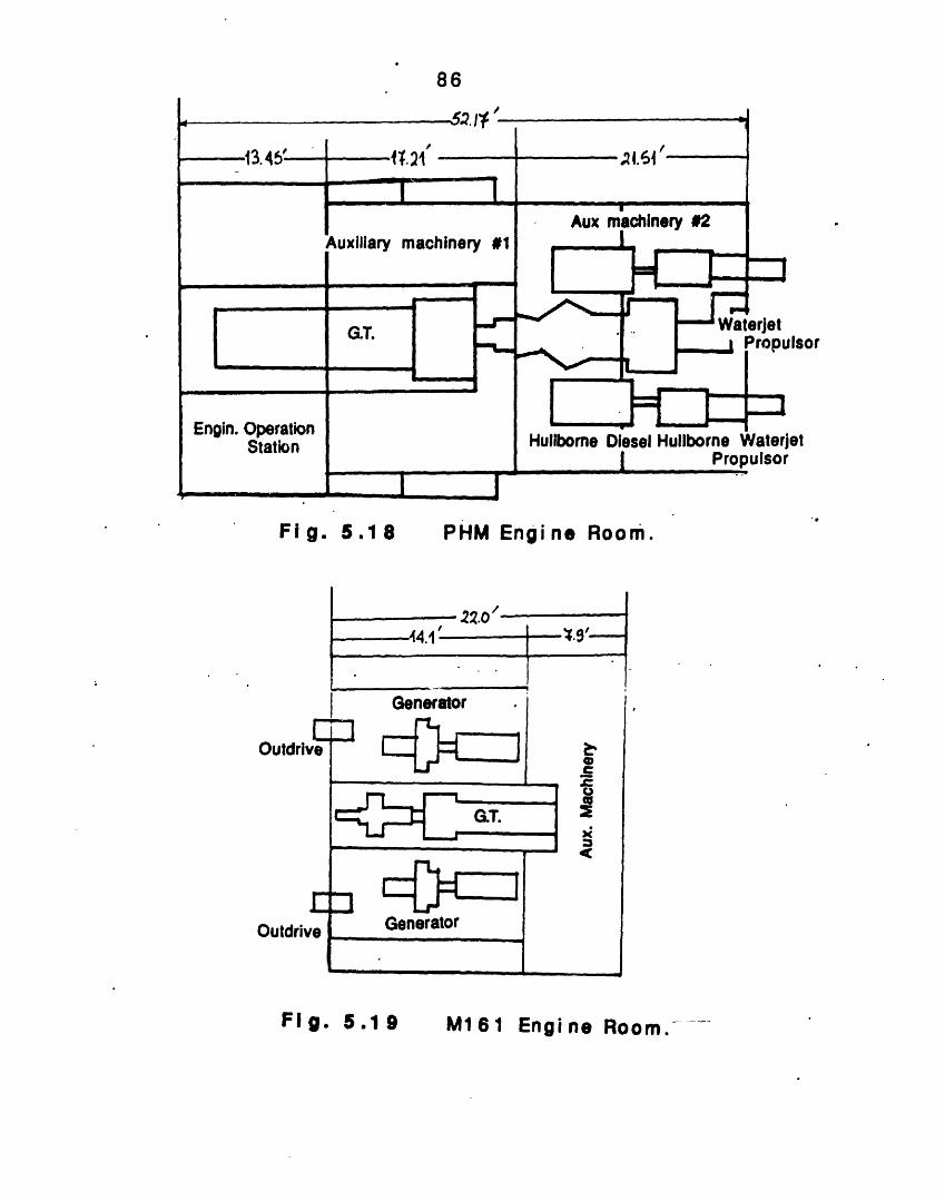
86
Fig. .18 PHM Engine Room.
Outdrbi
Outdri
M161 Engine Room.--.Fig. .1
87
,. t LL LIuMLaL LAILnL.RL.. Le
In this chapter structural design practices used forSESs and Hydrofoils is discussed. A comparison withmonohull design practices is also provided. Informationabout monohull's structural design practices can be foundat reference 25. The structural materials used to constructeach vessel are also presented. A structural weightanalysis can be found at the end.
5.2.1 SES st ruct ural design pract ice
The SES is asection is separatehydrodynamic Ioadidifferent means ofmonohul I.
ship in whichfrom the port ion
ng. SES depends f
weight support
the principal payloadof the hull affected byor its functioning on a(air pressure), than a
SES structural l oads.. are a strong funct.ioncenterbody-to-water clearance. When on cushiwetdeck is sufficiently high to reduce the stbending moments and permit high speed operationsspeed wit hout slamming.
Themonohul I
domi nanthead sea
of theon, theruct uralat high
design method for overall strength used for thes is not applicable for t he SESs. For SESs the mostload is the off-cushion longitudinal load due to
slamming i n survival sea st at es.
The SES vertical accelerations affect t he shipstructural loads, such as vertical bending moment andshear. In the case of a conventional ship the effect ofaccelerations is generally to reduce the bending--momentsince they act counter to the effects of buoyancy. In case
88
of a SES the main disturbing effects in waves are due tofluctuations in the cushion pressure, and the resultingaction of the vertical acceleration (which is effectivelyequi val ent t o t he pressure vari at i ons, si nce t he pressure i sthe main vertical sustaining force) results in an increasein the structural loads when the acceleration increases.Thi s behavi or i s opposi t e t o t hat of a convent i onal shi p.
The different domi nant load (compared to themonohull) coupled with the difference in how the SES issupported, leads to increased flexibility.for the designer.The shape of the SES can be adjusted to meet missionrequirements. The wetdeck height may be adj usted toprovide the optimum balance between structural loads (andt heref ore st r uct ural w ei ght ), mot i ons, and resi stance.
Other thangoverning loadswithstand. Oneship's lifetimeloading.
localwhichis the
and
For SES, the siirequires more strengtlifetime fatigue loadforces generated by wand also t he most di ff iexerted on the exposecurrently estimatedseaplane and plani ng h
and point loads, there are twot he ent i re st ruct ure of t he SES mustlargest single event load over the
the second is cumulative fatigue
ngle largest lifetime' load usuallyth than is demanded by cumulativeing. In the cushionborne mode theave impact are the most significant,cult to assess. The design pressuresed surface by the wave impact areon the basis of experience withulls, together with a limited amount
on operat i onal dat a on exi st i ng ai r cushi on vehi cl es.
The hullborne mode of the SESthe Catamaran. The ship is subjbending in head or following seas,beam seas, and torsion in quartering
is similar to thatected to I ongi t udi
spanwise bendingseas.
ofnalon
89
Structural design of a SES must take crew safety intoaccount. Crew members must be protected from injury thatmight result from an emergency condition such as a suddensharp maneuver or failure of the lift system. Suchconditions result in design accelerations of the magnitudeof 2 to 4 g's, depending on the direction of theaccel erat i on.
The magnitude of the factor of safety that is used inthe structural design is also influenced by the importanceof structural member being designed, the consequences oft he f ai I ure, and t he I i mi t at i on placed on st ruct ural wei ght .
5.2.2 Hydrofoil st ruct ural design pract ice
The structural design of a hydrofoil is similar to thatof a monohull, and can be found in reference 54.
The most severe loading consi dered for the hullpl at i ng of a hydrof oi I i s i n t he area between keel and chi nedue to wave impact pressure. The pressure equations thatare used do not include any dynamic magnification factor,because the natural frequencies of typical plating panelsare much lower than the frequencies of imposed pressureI oadi ng pulses.
A certain amount of permanent set for the individualplating panels is used in the hydrofoil ship hull design.This is due to the fact that very few hull placing panels,especially in welded construction, are initially flat. Thebottom plat i ng as well as t he bottom Iongit udi nal st r i ngersare loaded wit h t he same design impact pressures.
Transverse watertight bulkheads of the hydrofoil aredesigned for a salt water head to the main deck at midship.
90
In addition to the imust have the strengtlspeed, as well as distristrut attachment points.
nonohull design practice, theh to resist wave impact atbute the concentrated load at
The foil and strut design loads have their origins inthe weight and dynamic foilborne lift of the ship, and thedistribution of the weight or lift applied to the forwardand aft foil systems Two different kind of loads areconsidered for the foil and strut structural design.Vertical loads and transverse loads. The basic verticalloads needed for developing the design loads result fromthe moment balance of the ship when foilborne according tothe ratio of dynamic lift on the forward foil. The basictransverse loads required for the development of designloads are calculated in a manner similar to the basicvertical loads, except that an inertia load factor of 0.2g isapplied to the ship weight This lateral acceleration loadresults from a flat turn, and it is reacted by hydrodynamicside loads on the struts.
Four limit design load condithe structural analysis of theemergence, side maneuver and
tionsfoils:beam
must beMaxi mum
sea loads.
examinedfoil lift,
5.2.3 Structural Materials
SPICA II is an all Steel vessel, while all the otherships are constructed of Aluminum. CPIC is constructedwith Al 5456 Aluminum. The hull and superstructure of thePHM are constructed using welded Al 5456. The hull ofM161 is constructed of 5456 Aluminum using 5356 fillerrods. The forward deckhouse is of riveted ---6061- T6Aluminum. The aft deckhouse is of 5456 Aluminum. The
hul I
highthe
forfoil
91
structural design of the SES APB34 design was execcuted,considering Aluminum as the construction material.
Aluminium has a higherthan steel, but lower Ultirpressure and elongation. Alomnidi rect i onal st rengt hcorrosion resistant, is easilyassembled to hulls withouttool i ng.
maximum allowable deflectionnate Tensile Strength, Yielduminum is homogeneous, hascharacteristics, is highlyformed and j oi ned, and can bethe requirement of expensive
Al 5086 is an Aluminum alloy of the non- heat-treatable 5000-series. It has very good ductility in thewelds and minimal loss in strength when welded. Itrequires minimum protective coatings, generally only anti-f oul i ng pai nt f or underwat er areas, and no coat i ng t opsi de.It does require protection from cavitation and velocityerosion. Al 5086, although slightly inferior in mechanicalproperties to Al 5456, has less susceptibility in stresscorrosion.
Other series ofships studied areAluminum alloys. Forwelded const r uct i on,
alloys used for t he fabri cat ion of t het he Al 6000-series heat treatablethem, Al 6061-T6 is not suitable forsince the high mechanical properties
that are achieved by heat-treatment are lost during thewelding process. However Al - 6061-T6 has excel I entresistance to the marine environment, and the ability to beextruded into complex thin-gauge web-core shape. It isusually fabricated from integrally extruded shapes and isjoined by mechanical fasteners. The fabrication procedureof AI-6061-T6 is further complicated by the problem ofobtaining complete watertightness in the fabricationprocedure.
92
The Al 5456 structure of M161 is a longitudinal plateand grillage. Closely spaced longitudinal stiffeners areused. The longitudinal stiffeners consist of tees, result ina minimum weight design.
The basic materi al chosen for t he foi Is and struts ofthe PHM was a martensitic, preci pi t at i on- hardeni ngcorrosion resistance welded 17-4PH steel. Early in theoperational life of PM1, cracks appeared in the skins ofthe foils, due to material fatigue. Although the levels ofthe loads used were correct, the frequency of high loadswas much higher than what was anticipated. The foils thenwere redesigned using fatigue criteria, and the next PHMssail wit hout any operational problem.
In M161 hulls have relconsists of plate supported byin turn are supported by morframes and bulkheads. The tbeams are supported by systLongitudinal: bulkheads havedesign.
5.2.4
atively light plating whichlongitudinal stringers which'e widely spaced transverseransverse frames and deckem of longitudinal girders.not been i ncluded in this
Structural weight analysis (Table 5.3)
Overall hull weight fraction is a poor measure of thest r uct ural efficiency as it depends on how denselyequipment is packaged in the hull. Also differing governingloads make comparison difficult. Thus. in order to make awei ght anal ysi s t he st r uct ural w ei ght f ract i on i s used. TheStructural weight fraction (see figure 5.20) could bewritten as:
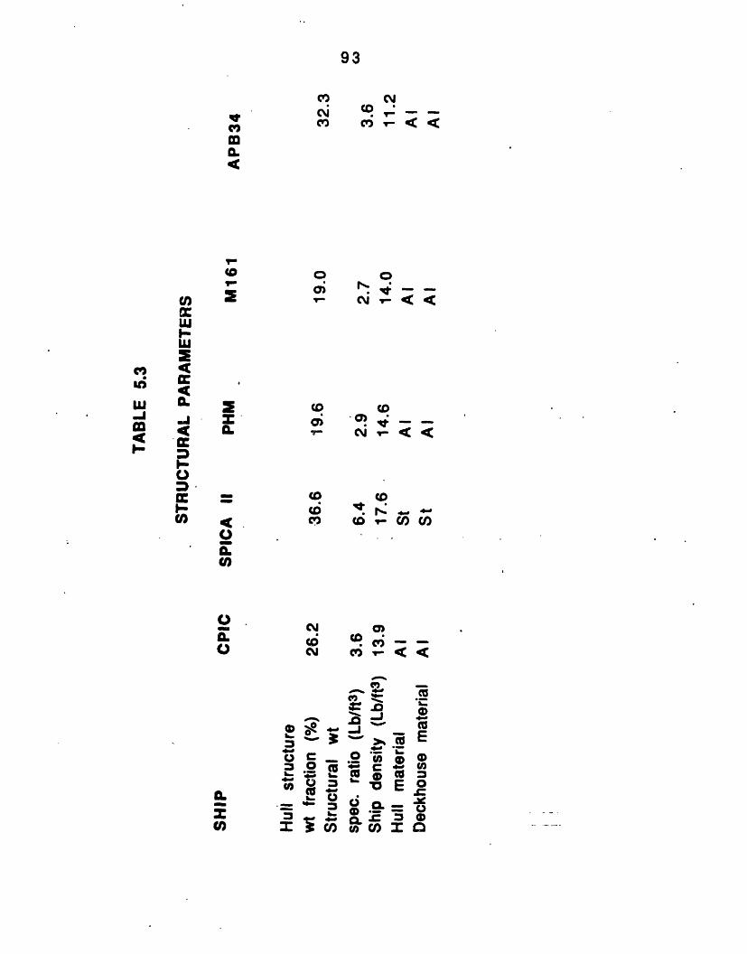
93
i c _ 61C>
Co _
CD -., O
CU o
cm CO r
I T.o !t
_ ,_j ._."O"
CO CCO
L )> CL t to n xI
-aSC
oE0g)00AC00a
IVco)
.
(
cn
wC/)-LU
C -
mJ
I-CO
:'IL
0)
CO
m
i,(aIll
a
CO
no
L-
0 o= o
.= _Io
X V
94
W1 / A=(W / V) x(V/l A)
From t
is largelyvol ume (t hevolume is art he vol mespecific volaf f ect ed b)di spl acemenratios, penefigures 5.21between shifor the four
lE
di
above relation we can see t hat, t hisriven by the total hull structurenverse of the ship density). The ship
fractionspecificspecific
i indication of the spaciousness, and how muchrequirements drive the design. The larger theume, the more spacious the design is. It is
y many variables including length, volume,t, hull form, local loading, ship dimension)trations, frame spacing and materials. From
and 5.22 we can see that there is a trade-offp density and structural weight specific ratioaluminum ships. The denser the ship, the less
structural weight is used for a unit of vol ume.
Figure 5.23 shows the fraction of the differentcomponents of structural weight. The exact structuralweight fractions for groups 110-180 can be found on table5.4. APB34 was not included in this analysis as no datacould be found or created for the structural components.
The shell ofenvelope that keistrength memberthe web of the gbottom flange inIoading. SPICA I,high shell and sudue to the use ofthe frame weight
aeps
shipthe
issea
thatout,
part of tand it as
he watertightthe principal
of the hull girder. The side shell acts asiirder, and the bottom shell acts as theresisting the primary bending and shearthe only steel ship of the study, has verypport weight fractions. This is probablymore transverse frames, which increasesignificantly. The hull form of SPICA II
with a deep Vee forward requires transverse
hE
f rames for
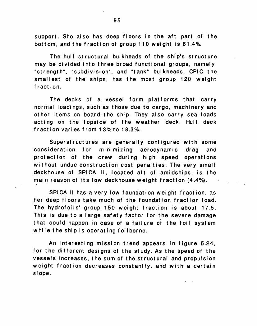
95
support. She also has deep floors in the aft part ofbottom, and the fraction of group 110 weight is 61.4%
the
The hull structural bulkheads of the ship's structuremay be divided into three broad functional groups, namely,"strength", "subdivision", and "tank" bulkheads. CPIC thesmallest of the ships, has the most group 120 weightfraction.
The decks of a vessel form platforms thatnormal loadings, such as those due to cargo, machinerother items on board the ship. They also carry seaacting on the topside of the weather deck. Hullfraction varies from 13%to 18.3O/
carryy andloadsdeck
Superstructures are generalconsi derat i on for minimizingprotection of the crew duringwithout undue construction costdeckhouse of SPICA II, locatedmai n reason of its low deckhouse
ly configured with soaerodynamic draghigh speed operat i
penalties. The very smaft of amidships, is weight f ract ion (4.4%°/).
meandons
allthe
SPICA II has a very low f oundati on weight f raction, asher deep floors take much of the foundation fraction load.The hydrofoils' group 150 weight fraction is about 17.5.This is due to a large safety factor for the severe damagethat could happen in case of a failure of the foil systemwhile the ship is operating foilborne.
An interesting mission trend appearsfor the different designs of the study. As tvessels increases, the sum of the structuralweight fraction decreases constantly, andslope.
in figure 5.24,he speed of theand propulsionwith a certain
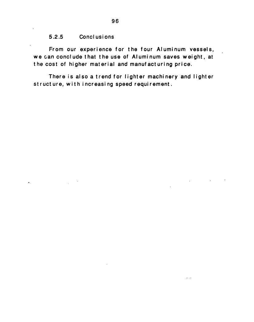
96
5.2.5 Concl usi ons
From our experience for the four Aluminum vessels,we can conclude that the use of Aluminum saves weight, atthe cost of higher material and manufacturing price.
There is also a t rend for lighter machi nery and light erst ruct ure, wit h i ncreasi ng speed requirement.
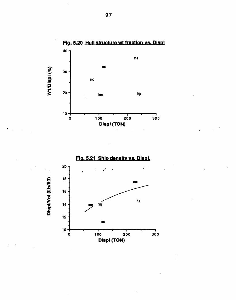
97
Fig. 5.20 Hull structure wt fraction vs. Dispi40 -
30 -
20 -
0
mS
uS
me
hm
100100 200
hp
300Displ (TON)
Fig. 5.21 Ship density vs. Disol.20
J 16-O
14o.0
12 -
10-0
Displ (TON)
7r,co
I-
10
ma
hm-r
SO
100 200 300
� II I
,,
J ~
A~
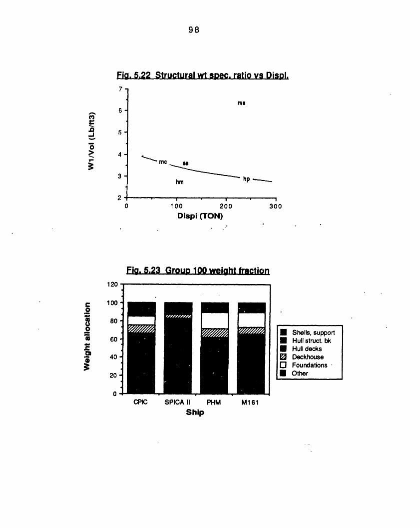
98
Fig. 5.22 Structural wt spec. ratio vs Displ.
-
6-
5.
4-
3-
0
mS
hm
100 200
hp -- _
- !300
Displ (TON)
Fig. 5.23 Group 100 weiht fractioniuI
C 100.O
~a 80-
0 60 .
40o I
0 -CPIC SPICA II
ShipPHM M161
A
.0v
I-D-j
* Shells, support* Hull struct. bki Hull decks0 DeckhouseO Foundations* Other
III , _ ,II _ A __ _
II
I
Z
"I
n nlI

99
Fia. 5.24 Struct. +Propuls. wt fraction s. max speed,-
CL , 40-0
N
+ 30-
3O
20 I . I . , . . . I
Vmax (KT)40 42 44 46 48 50 52 54
bu -
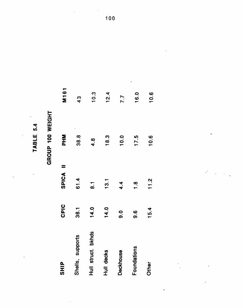
100
co 0 C04110 T
o coO 0D
r- .. s to
co o L o_? . r; c;v V- V - r
"tSco
1-S CVC,7 C i
o o0r 0 0C' '-S
C, - V
U)
.0
4.'.Xm*jj
I=1
CV
o cD e0 0 l'
mu 0
a) O c 010 0 m
e C 0 0I CL) .
D
V-
C
0
w 0-i .-
0Ix
. coIL c
Co
m
0o
a.- CD
M0).CCI
0
101
i3 ELEIRLCALEQWJBi
The electrical power weight fraction indicates towhat extent the electrical system drives the design. Table5.5 summarizes all the indices associated with theelectrical system of our ships. The electrical power w eightship size trend could be seen in figure 5.25. The W3/Acould be written as:
W3/ A=(W 3 / E)x(E/ WPAY) X (WPA/ A)
From this relation we can see that the weight used forpower is impacted by the design standards, the efficiencyof the payload in consuming power, and the ability of theship to carry weaponry and command systems. Instead ofthe payload weight fraction, the weight fraction of thepayload and the auxiliary systems fraction could be used,but the auxiliary systems are considered as a function oft he payload for simplicity.
The payl oad w ei ght f ract i on var i es18.6%. This variation is not consideredthe allocation of the electrical weight,the following lines.
bettheas
The electrical weight specific ratio is aof the electric weight-to-KW efficiency oflower ratio indicates that the plant has thedel i ver i ng more pow er f or a gi ven w ei ght .
ween 13.3%;main driver 1we shall see
andfor
in
measurementthe plant. Acapability of
The i nef f i ci ency of t he smal I gener at or i nst al I at ithe CPIC drives its electrical weight specific ratiohigh. (See figure 5.26)The two hydrofoils and theAPB34 have approxi mat el y t he same W3 / E rat i o and f orreason the electrical weight fraction of the M161
on ofverySESthisand
102
APB34 should be considered high. Recall that PHM uses alight 400Hz distribution system. Likewise, M161 and APB34are designed with most modern electronic, and distributionsystems which require less electrical plant weight per KW.
M161 has the most efficientamount of power is required in orHere we can see a direct linkweight fraction and the Electriratio, as can be seen from figurethe payload, the less fraction of 1for its electrical system.
pavload, as the smallestder to "feed" its payload.
between the Electricalcal power payload size5.27. The more efficient
tine ship's weight is used
Observing figure 5.28 we can see the size trend ofelectrical power ship size ratio. As the ships beclarger the less power per displacement is needed forships needs. From this rule CPIC is excluded, due toinefficiency of its small generator installation.
theomethethe
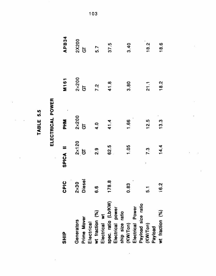
crmIL4
ooCMjX 3oJl
V- O
(0 CN-C1
o= C
X
0
u'4
(0
o X .oo x C.) C
Lo
U) c
CN It
0 It:O .
Le)
a9! CaJCM co
co
Cd r(D V-
O O O 0o
L 0 E 4- rc~~~i. (1 :F.,V) O - u ,
B 3 o 31. C CO CLI..0~~
> o w or_ *aV*( a° eD -. 0* _. _ -
8 O .Q UJ = -
ch LLJ
103
Ll
Yo 0mi I.
m 0
-Juo
-J,U
oc,
co
co
coo
o
N6 CD
,- C
U) cv,
N- c
cv,Cli 1I,- T
cN
CDU)
0
0tv(DNn'Dcd0--(U
0.*
A
co c
o %.. (
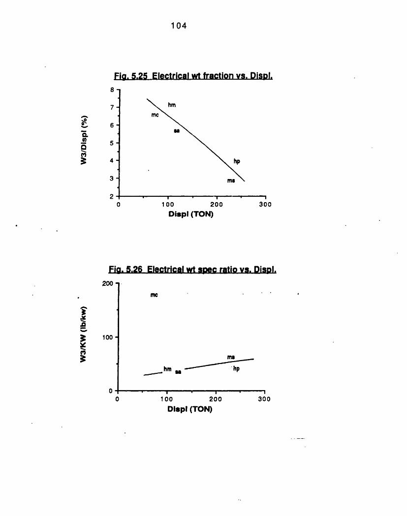
1 04
Fig. 5.25 Electrical wt fraction vs. Disp.
0
hm
mec
hp
100 200 300DispI (TON)
Fig. 5.26 Electrical wt soec ratio vs. Disol.
mc
hm
100I0 30
200 300Displ (TON)
8
A
mmQo~iraQ
6-
5-
4-
3-
zuu
IFm
0
3:
x100
0
0
n * w I I
I . -
.. r
id
J"AA
Ms.hp
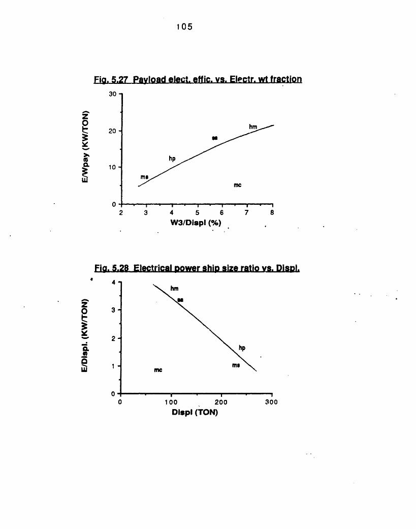
105
Fia. 5.27 Payload elect effic. vs. Electr. wt fraction30
20 -
10-
0
a
hp
mamc
I I i - i I
2 3 4 5 6 7 8
W3/Displ (%)
Fig. 5.28 Electrical power ship size ratio vs. DisDl.
hm
hp
100 200Displ (TON)
0
A.OtQ-
z
Q.
L
4.
3-
2-
1-
0
0 300
L_
. . - . X
.
..
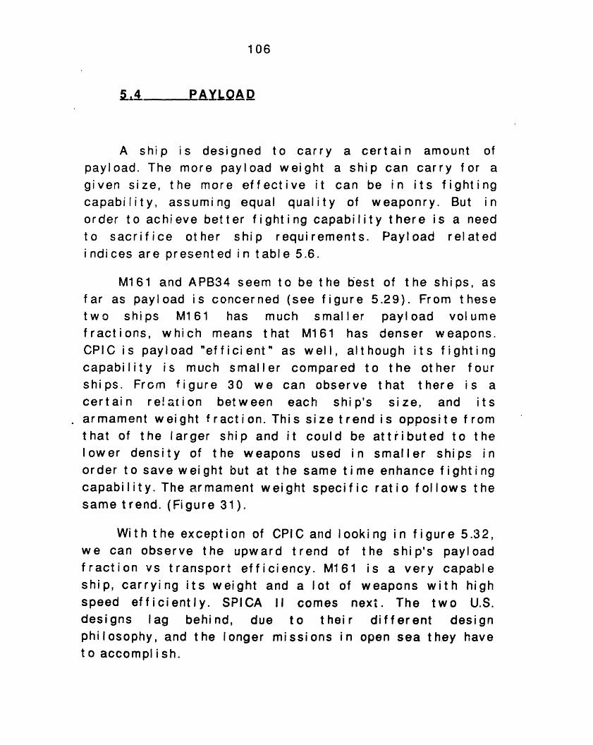
1 06
5.4 PAYLOAD
A ship is designed to carry a certain amount ofpayload. The more payload weight a ship can carry for agiven size, the more effective it can be in its fightingcapability, assuming equal quality of weaponry. But inorder to achieve better fighting capability there is a needto sacrifice other ship requirements. Payload relatedindices are presented in table 5.6.
M161 and APB34 seem to be the best of the ships, asfar as payload is concerned (see figure 5.29). From thesetwo ships M161 has much smaller payload vol umefractions, which means that M161 has denser weapons.CPIC is payload "efficient" as well, although its fightingcapability is much smaller compared to the other fourships. From figure 30 we can observe that there is acert ai n re! t i on bet w een each shi p's size, and itsarmament wei ght f ract i on. Thi s si ze t rend i s opposit e f romthat of the larger ship and it could belower density of the weapons used inorder to save weight but at the same timcapabi I i t y. The armament wei ght speci f i csame trend. (Figure 31).
attributed to tsmaller ships
e enhance fightiratio follows t
With the exception of CPIC and looking in f igure 5.32,we can observe the upward trend of the ship's payloadfraction vs transport efficiency. M161 is a very capableship, carrying its weight and a lot of weapons with highspeed efficiently. SPICA II comes next. The two U.S.designs lag behind, due to their different designphilosophy, and the longer missions in open sea they haveto accompl ish.
heinng
he
LL - ' L·; L4--
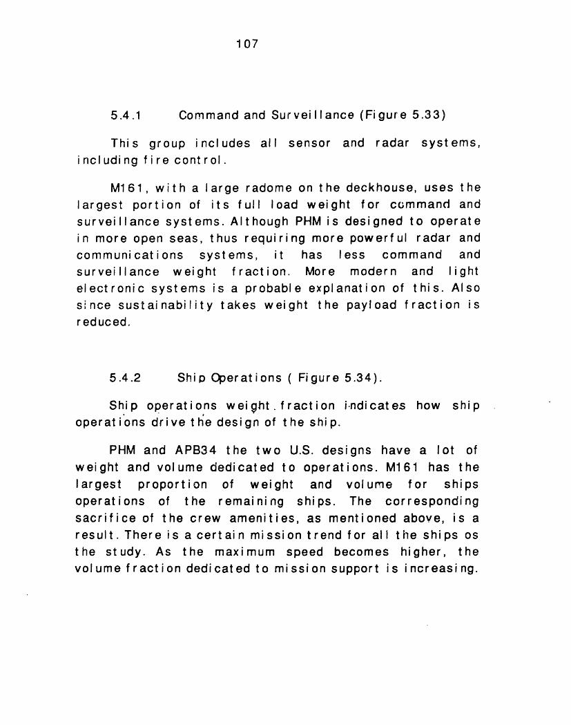
107
5.4.1 Command and Surveillance (Figure 5.33)
This group includes all sensor and radar systems,including fire control.
M161, with a large radome on the deckhouse, uses thelargest portion of its full load weight for cmmand andsurveillance systems. Alt hough PHM i s designed to operatein more open seas, thus requiring more powerful radar andcommuni cat i ons syst ems, it has less command andsurveillance weight fraction. More modern and lightelectronic systems is a probable explanation of this. Alsosince sustainability takes weight the payload fraction isreduced.
5.4.2 Sh i p Operat ions ( Figure 5.34).
Ship operations weight.fraction indicates how shipoperat ions drive t he design of the ship.
PHM and APB34 the two U.S. designs have a lot ofweight and volume dedicated to operations. M161 has thelargest proportion of weight and vol ume for shipsoperations of the remaining ships. The correspondingsacrifice of the crew amenities, as mentioned above, is aresult. There i s a cert ai n missi on t rend for all t he shi ps osthe study. As the maximum speed becomes higher, thevolume fraction dedicated to mission support is increasing.
o- CO) ,wi CD 0
Cu o co Cu u6 06 (,i U~i °T- V- C ~n
cV) C)
CI, co
't "t
CW TD C)
0c
CD C)
0;. O,,,--
4.'-
-.. _C 0DO : O , -
o >n
Mv o ° 0a. > O -a
1 08
oD 00, 0
COa-
If-CD
ui
,m
I-
o ·-J
a.ax
UC,,
CE)
U.40
C,
O
0o 0 -0 m
_L %
m
-j0
0
a0.
-.
E 3E.- or - Cc DzE ro EEco Ec_'O" E
&Z (a &
109
Ln
10 0
7-
D
CD CD
I
u0) Or
D0C;c
0 0o C.)C C
ca
EEo.n .5+r ++ C +
EccE00:0n C)
cD r.*O * O,
cj c ¢
cD md -
ci c v c0 (6
CM Cn Ck)
T- o
C# mo
mI _ rt
0 0C O
O *9 ~a c- *.m Q D O CO _J cn 3, 2, I .0-.2 c . ils r(i CL 6co UP) COcn3
0-o
0Q .
0 O>cn >
cnz0U)4uiw
-J
Ir0C,,
110
Fi. 5.29 Paload wt fraction vs. max speed
40
6ahm
mc
hp
I4 ' ' bI ' I ' ' ' ' I '48' I 542 44 46 48 50 52 54
Vmax (KT)
Fig. 5.30 Armament wt fraction vs. DispI.
17
15
, 13-
11O.
0 9-
5
3-
1
0
hm
66
m hp
Dlspl (TON)
20 -
19
18-
17-
16 -
15
14 -
't
O0
3.
13
12
100 200 300
·II -i .. . . . . . . . .I__-_ __i
_ I L I
111
Fia. 5.31 Armament wt spe. ratio vs Displ.3-
2-
1-
00
hm
me
SI
100
hp
200 300Displ (TON)
Fig. 5.32 Payload wt fr. vs. TransDort effic.
21 -
19
17
15 -
13
11
0.3
mehm
me
S.
0.50.5
I
0.7 0.9 1.1
Transport effic. (TON*KT/HP)
C,,
-JZ
A
PI
a
Q,
[
w wva
1 I 11 ....
i
"I,
I
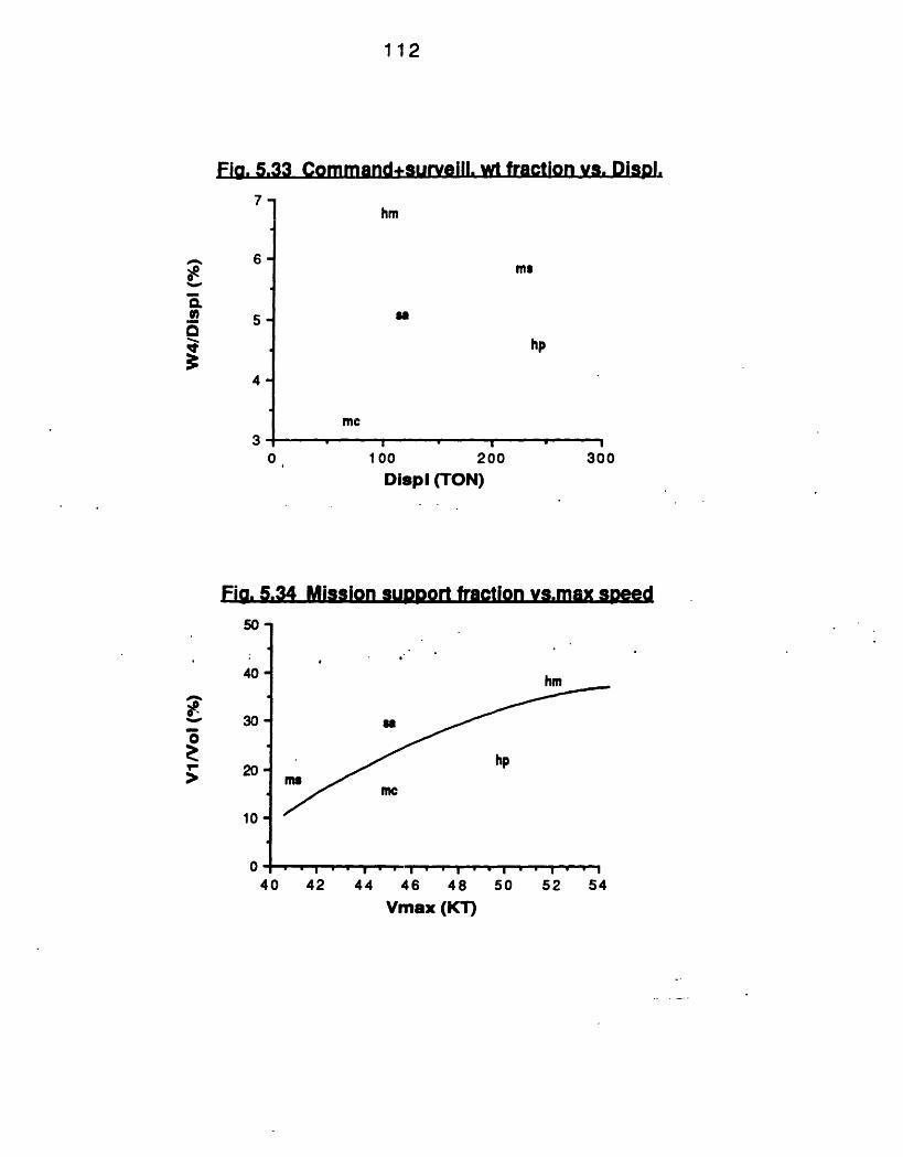
112
Fig. 5.33 Command+surveill. wt fraction vs. Displ.
(.
6-
5-
4-
3
hm
mg
Is
hp
me
0 100 200 300Displ (TON)
Fig. 5.34 Mission SUDDOrt fraction vs.max speed
.U.
40
30
20 -
10 -
040
hm
as
hp
mc
A
ate.
-
BVI
' I . . . . I -I
42 44 46 48 50 52 54Vmax (KT)
. . X .. . . I
BI Iml II I
~A
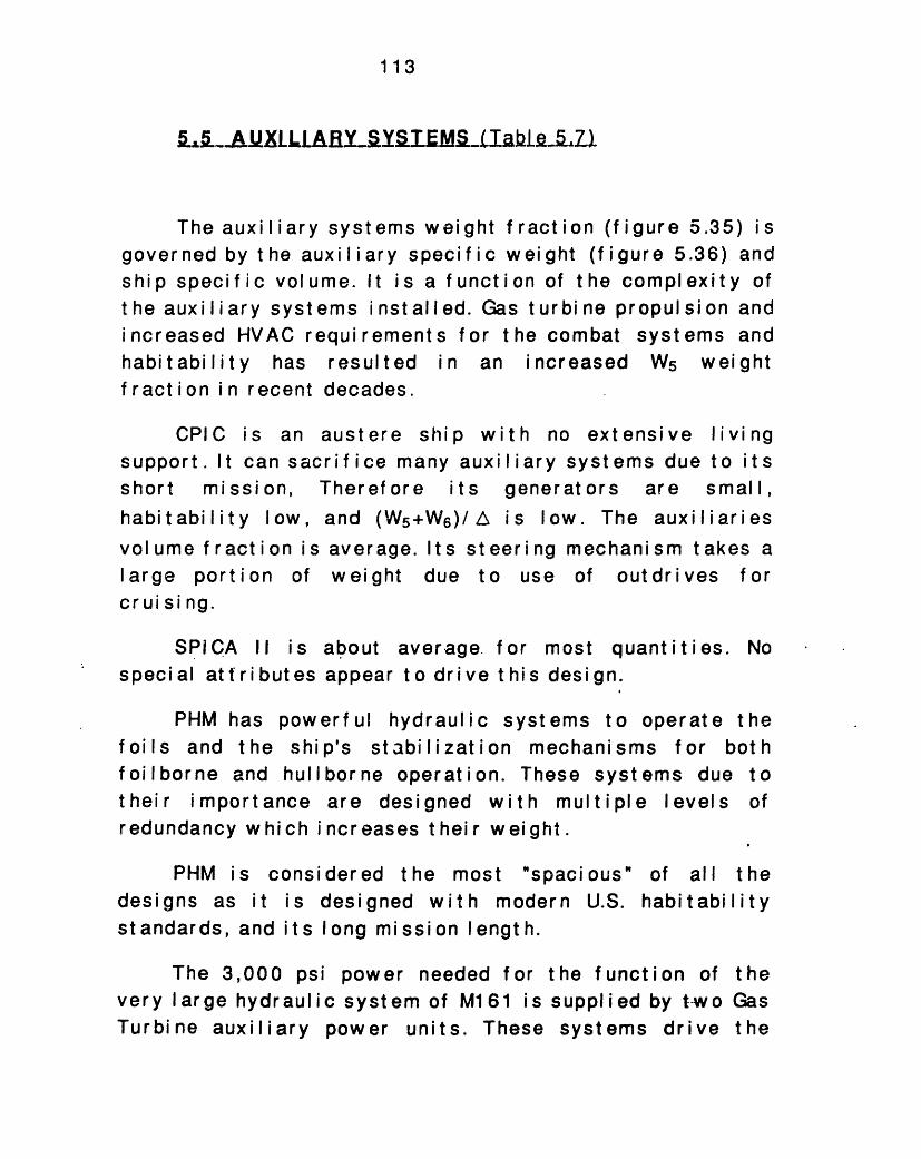
113
The auxi I i ary systems weight f raction (f igure 5.35) isgoverned by t he auxi I i ary specif ic weight (f igure 5.36) andship specific volume. It is a function of the complexity ofthe auxiliary systems installed. Gas turbine propulsion andincreased HVAC requirements for the combat systems andhabitability has resulted in an increased W5 weightf ract ion i n recent decades.
CPIC is an austere ship with no extensive livingsupport. It can sacrifice many auxiliary systems due to itsshort mission, Therefore its generators are small,habitability low, and (W5+W6)/A is low. The auxiliariesvol ume f ract i on i s average. It s st eer i ng mechani sm t akes alarge portion of weight due to use of out dr i ves forcruising.
SPICA II is aboutspecial attributes appear
average, for most quantities.to drive this design.
PHM has powerful hydraulic systems to operate thefoils and the ship's stabilization mechanisms for bothfoilborne and hullborne operation. These systems due totheir importance are designed with multiple levels ofredundancy which increases t heir weight.
PHM is consdesigns as it isstandards, and its
idered the most "spacidesigned with modernlong mission length.
The 3,000 psi power needed forvery large hydraulic system of M161 isTurbine auxiliary power units. These
the function ofsupplied by twosystems drive
No
ous"U.S.
ofhabi
allt abi
theI ity
theGasthe
�,,�i,_BILXLILBB1L,�iY�iZE�J��S,/lahl�t�
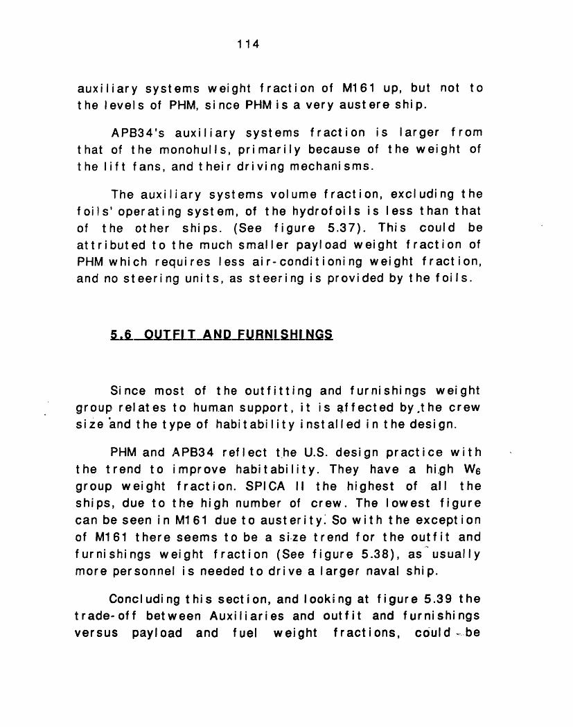
114
auxiliary systems weight fraction of M161 up, butt he levels of PHM, si nce PHM i s a very aust ere shi p.
APB34's auxiliaryof the monohulls,if t fans, and t heir
systems fraction isprimarily because ofdriving mechanisms.
largerthe wei
The auxiliary systems volume fraction, excluding thefoils' operating system, of the hydrof oils is less than thatof the other ships. (See figure 5.37). This could beattributed to the much smaller payload weight fraction ofPHM which requires less air-conditioning weight fraction,and no steering units, as steering is provided by the foils.
56 OUTIT ATNDElBNLILLNG
Since mostgroup relates tosize and the type
of the outfittihuman support,of habitability
ng and furnishings weightit is affected by.the crewinstall ed i n t he design.
PHM and APB34 reflect the U.S. design practice withthe trend to improve habitability. They have a high W6group weight fraction. SPICA II the highest of all theships, due to the high number of crew. The lowest figurecan be seen i n M161 due t o aust er i t y So w i t h t he except i onof M161 there seems to be a si-ze trend for the outfit andfurnishings weight fraction (See figure 5.38), as usuallymore personnel is needed to drive a larger naval ship.
Concl udi ng t hi s sect i on, and I ooki ng at figure 5.39 thetrade-off between Auxiliaries and outfit and furnishingsversus payload and fuel weight fractions, could ..be
t hatthe I
not to
f romght of

115
observed. Sacrifice of auxiliaries and furnishings givesmore weight f ract ion t o payload and fuel.

oC)
o , X
. xN II T q Xcj, 0 v
- Nv-
' C
co I-ad r
· D C\. CxJ,It I- v C
O0CD
oCI'-
0)co
CD,D ,.U r 'xT- C
V ' ~) .0 , .
u) 0 ( / *
~~; s .: =tco o'sO o'u m0 cu .h....0 ->:0.- * -- ~~~~~~~.- U co~~~ES CC
c0
C
D
C(OnO3
0
'BcCCcnC
0.
-o
C)OO, -.
CQ O O
-,- : .- :_ _ I
0 0.o o-c Sl I
U0,1
116
am
4
v.
TM
0
CC,
m
1*(f)
u) 0
1- :t
N 0)
(0CDCr
Goc0
Co0)
w
4 Za.xCIuW
mi-.4;
4
Co
,
cnE
cn
co01
: UU) .Cua. =
, ,. ,p _-
I
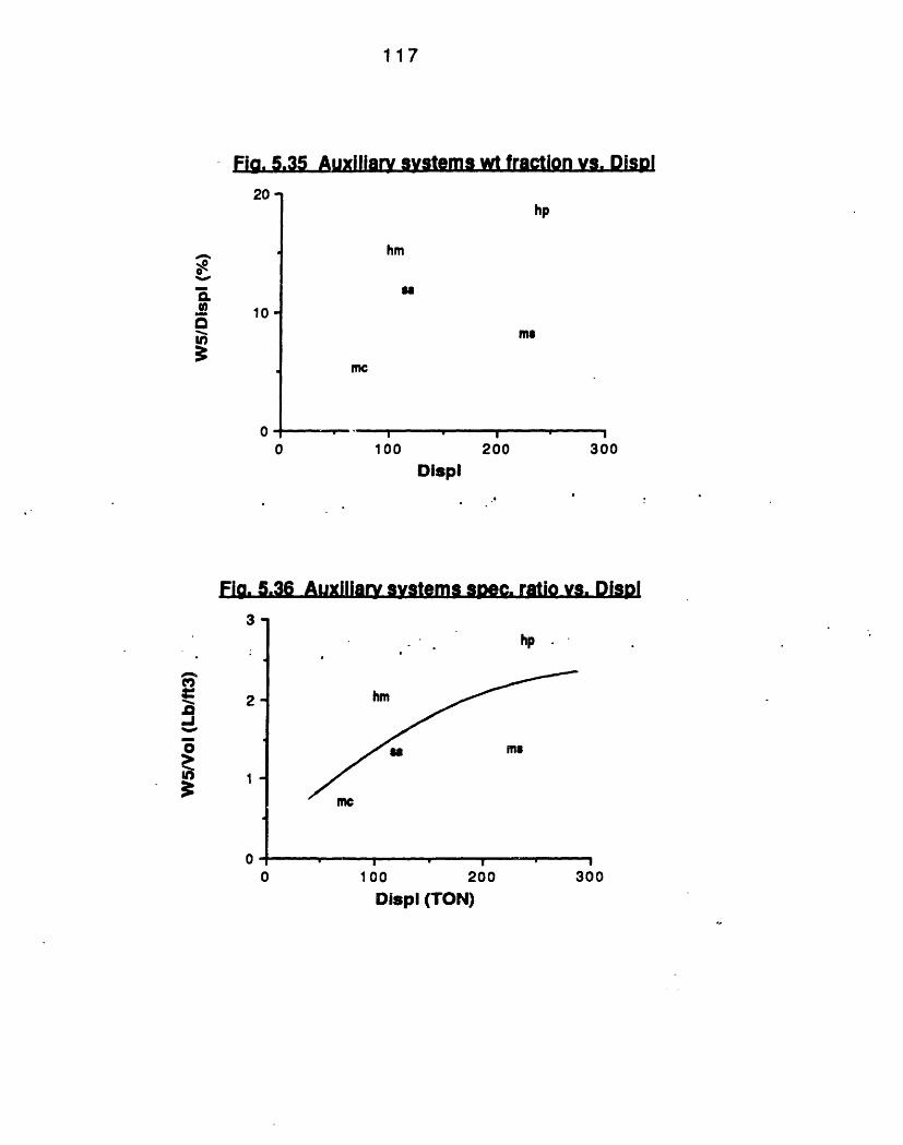
117
-Fla. 5.35 Auxiliary systems wt fraction vs. DisDI
1u
10
00
hp
hm
61
me
me
100100
I200
3300
Displ
Fig. 5.36 Auxiliary systems sDec. ratio vs. DisDI
3
2
1
0
300
Q.00
on
.0JIU)
0 100 200Displ (TON)
I IIII ~1111 II II I IIII I II I
,,
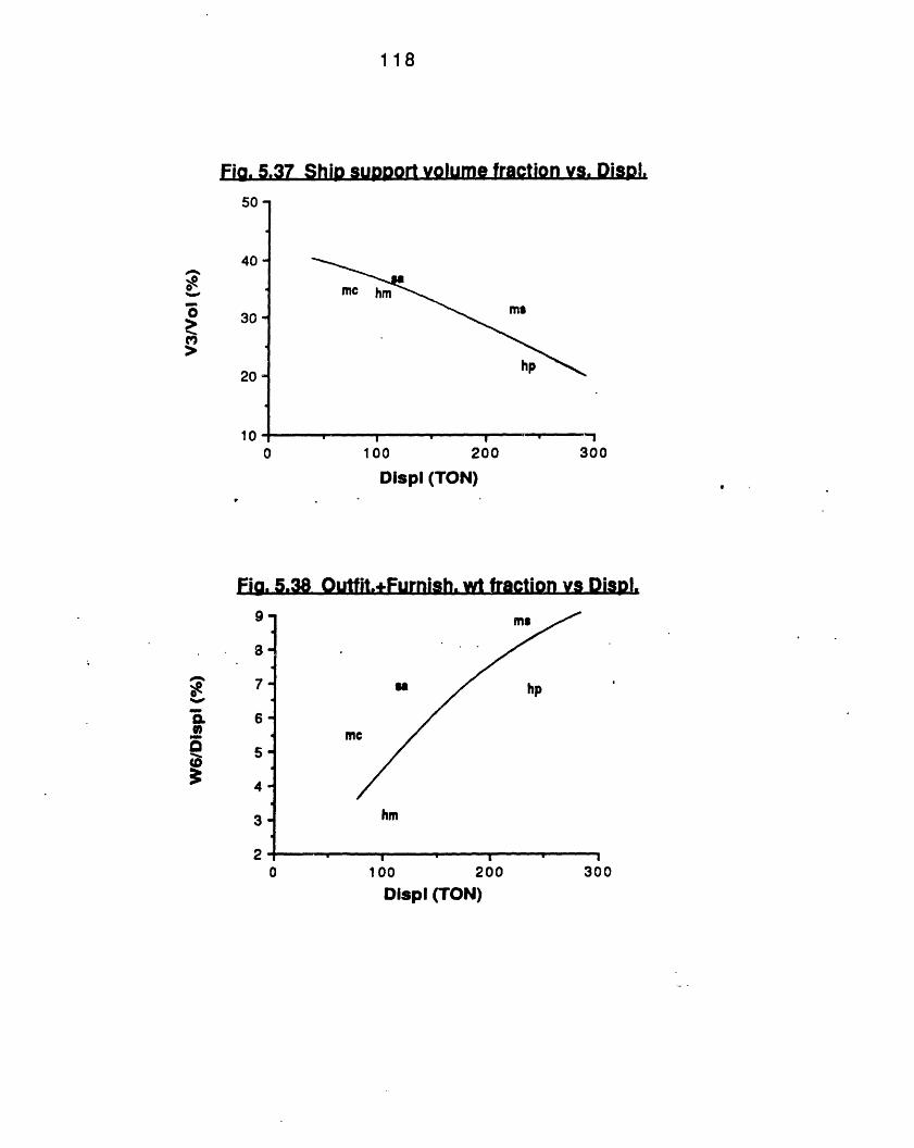
118
Fig. 5.37 Ship supDort volume fraction vs. DisDI.
50
40-
30 -
20
10 0
mc hm
ms
hp
- ' -00 200 3001
Displ (TON)
Fig. 5.38 Ouffit.+Furnish. wt fraction vs DisDI.9-
8-
7-
6-
5 -
4-
3-
20
ms
$a hp
mN
hm
100 200 300Displ (TON)
0..
'I75m
0-v
-'a0isalQ._m
. I II
·II - I .II
I
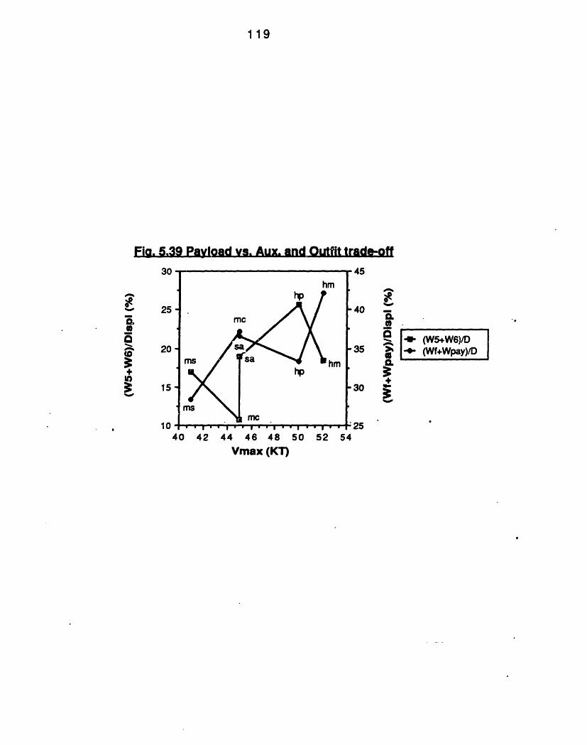
119
Fig. 5.39 Payload vs. Aux. and Outfit trade-off30
25 -
20
15 -
10 .I .
40 42I ' ' ' I 'I
44 46 48 50Vmax (KT)
52 54
" 5
OR
-40 -&
0.a
-35 P
-30 9
:25
0%A
aa
tt)
hm
mc
hm
n
l Z l lbI
-W (WS+WGY) D-0- (Wf+Wpay)D~
rl __l ............... w w w w w w·
| w w g
r
I .i I ·.
120
The desider at i onsnumber o
gnaff
indices showing howfect the design are shownaccommodations impacts t
inhe
personneltable 5.8.
ship byrequiring space, weight and energy. The amount of crewcarried aboard a ship depends firstly upon the mission ofthe ship as well as the mission length, and payload. Asecondary considerat ion i s t he amount of automat ic controlon board, the efficiency of the personnel, and each navy'sstandards on personnel education, and philosophy onequipment maintenance and repair. After the crew size isselected, national preference has a large impact on spaceand weight dedicated to the ship's crew.design their ships with an "austere"regarding volume dedicated to personnel"standard" and others with "plush". So the manni ng shi p si ze rat i o t he more ef f i ci ent t Ia manning perspective.
Ot her n
classific, otherower thehe design
PHM and SPICA II are the two ships that can stay onmission longer than the other ships, which with theexception of CPIC, can be considered as "day boats". SPICAII has a difference of 40% of manning ship size ratio fromPHM a vessel of the same displacement, probably becauseof the different kinds of weaponry systems SPICA IIcarries. There seems to be a economy of scale concerningthe crew a vessel can carry. This economy of scale isdemonst rat ed i n f i gure 5.40.
The personnel weight fraction is larger in the shipsw i t h Ionger mi ssi ons as expect ed.
consiThe
avi es
:at i onwithtotalf rom
ILL 2-f; Rag MIL
121
The personnel vol ume specific ratio (f igurevaries fromroomiest shiwell as theneeds sustaiiis still redLhabitabi I ity15 men arehabitabilitycharacteri stifigure 5.42 personnel vol
136 8p duemoder
nabilitj
(APB34) toto the U.S.n systems
Y- Thi s
iced in SPICAcould is in M1on board. M16
can be acs when missian upward sizeume f ract ion.
350.8 (PHM).habitability s
and longer mi
PHM
tandassion
isrds
w
the, ashich
means more space. HabitabilityII and in APB34. The worst
61, when its maximum crew of;1 is a great example on how
trade-off for per f or manceon duration is short. Looking ate trend can be with concerningThus the bigger ships allocate
more of the total volume for crew needs.
LL. CHAPTER 5 . RMMA
Chapter 5 identified and explored the differences oft he three various designs. General I ly we can state t hat theCODOG plant s and the diesel propulsion cost more than thegas turbine propulsion plants. Ship propulsion weight ratio,is a good way to increase speed, but at the penalty ofhigher cost.
The hydrofoils are most maneuverable and have abetter seakeeping capability than the other ships. But inorder to achieve this performance their cost, due toexpensive control systems becomes high compared to theot her shi ps. APB34 i s rat ed second, as f ar as seakeepi ng i sconcerned, but its cushion pressure control systems needimprovement.
Waterj ets are less efficient than the propellers, butat t he same t i me noi seless compared t o t hem.
5.41)

122
The 400 Hz electrical distribution system of PHM islighter than t he 60 Hz of all the other ships.
Al umi num saves weight, but increases buildi ng cost.
Finally in order to save weight for propulsion fuel(increase range), and in order to save weight and space forthe payload, different trade-offs are made by the differentdesigners, depending on the country for which the ship hasbeen built, its designed mission, and the amount of time ofits exposure at sea.
The attributes and limitations of each ship arepresented i n chapter 7.
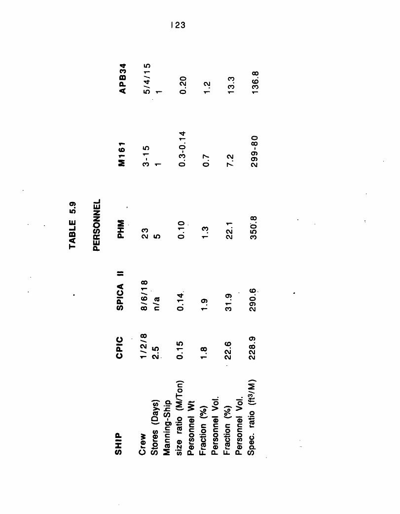
123
k I
m q-eLO-
D
2'
0.-
x
Uu,
In
C',
oO
C'
O1�
0.C) CN U) o
co
_ C
co
0 - _ uU
co .Q> Ccoe u,0
C
IL @ ° C0 .cCD o ch
I.
CLU)
t-
0O.wOw
N X C(O
rl_ CM) C)O0 cc j
co(7 0
l N C')T- C #
CD .
a) . O2 Y- a)
CO C
_- CY CN1. CY CY
I
01-1
0
C CO C
0C wlL Q)m % .
_0
C CO C
O( 0L -lLL 13
C'2cn
UI-
0to
0.Q,
cn
0)uiW u
I c
-J 0
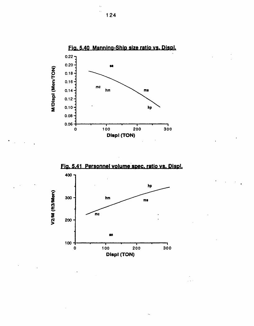
1 24
Fig. 5.40 Manning-Ship size ratio vs. Disopl.
0.22 -
0.20-
0 0.18-
t 0.16-2%-, 0.14-
c0 0.12-
0.10
0.08-
0.06
U
mehm m
.ol,
0 100 200 300Displ (TON)
Fig. 5.41 Personnel volume spec. ratio vs. DispDI.
400 -
300
200
1000
hD
hmme
as
- I100100 200 300
Displ (TON)
cS
N. .
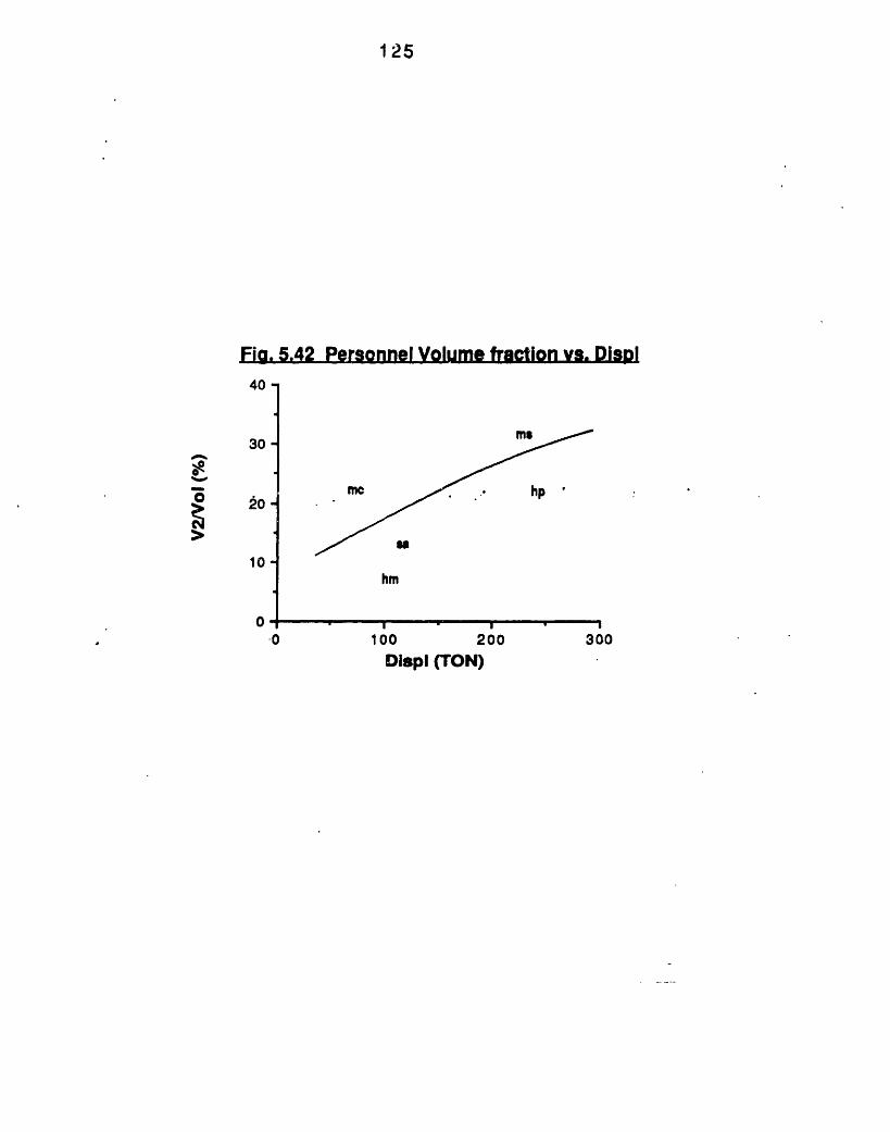
1 25
Fig. 5.42 Personnel Volume fraction vs. Displ
4U I
30-
0 ~20-> 20
10
0
hm
I " I
·0 100 200 300Displ (TON)
126
CHAPTER 6
PRODUCI BI LI TY
One of the chronic problems with military vessels hasbeen a lack of large production quantities to lower capitalinvestment per ship and to permit selection of productionmet hods which could achieve reduced unit cost s. Duri ng t herecent years, there has been more willingness ofcontractors and vendors to commit to approaches enablingreduced unit costs based on quant ity production.
In t hi s chapter, t he produci bility concepts used i n t heconstruction of SESs and hydrofoils will be discussed. Theconstruction methods of SESs and hydrofoils are becomingmore and more ef f i ci ent, as t hey borrow many produci bi I ityconcepts from the well-experienced aerospace industry.Producibility for monohull small craft is documented inreference 28.
611 Cnventin a h uLLI andESI-rQdcLIa L ty
One of the producibility concepts that is incorpoiatedin the construction of conventional Aluminum hulls is theinverted construction. In this way, transverse andI ongi t udi nal f rami ng can be set up and shell pl at i ng can bewrapped around the hull unobstructed by support i ngstructure. Gravity is helping with the plating job, externalshell seams can be welded flat, and there is far lessaccumulation of derbies inside the hull. The structure issupported by ji gs.
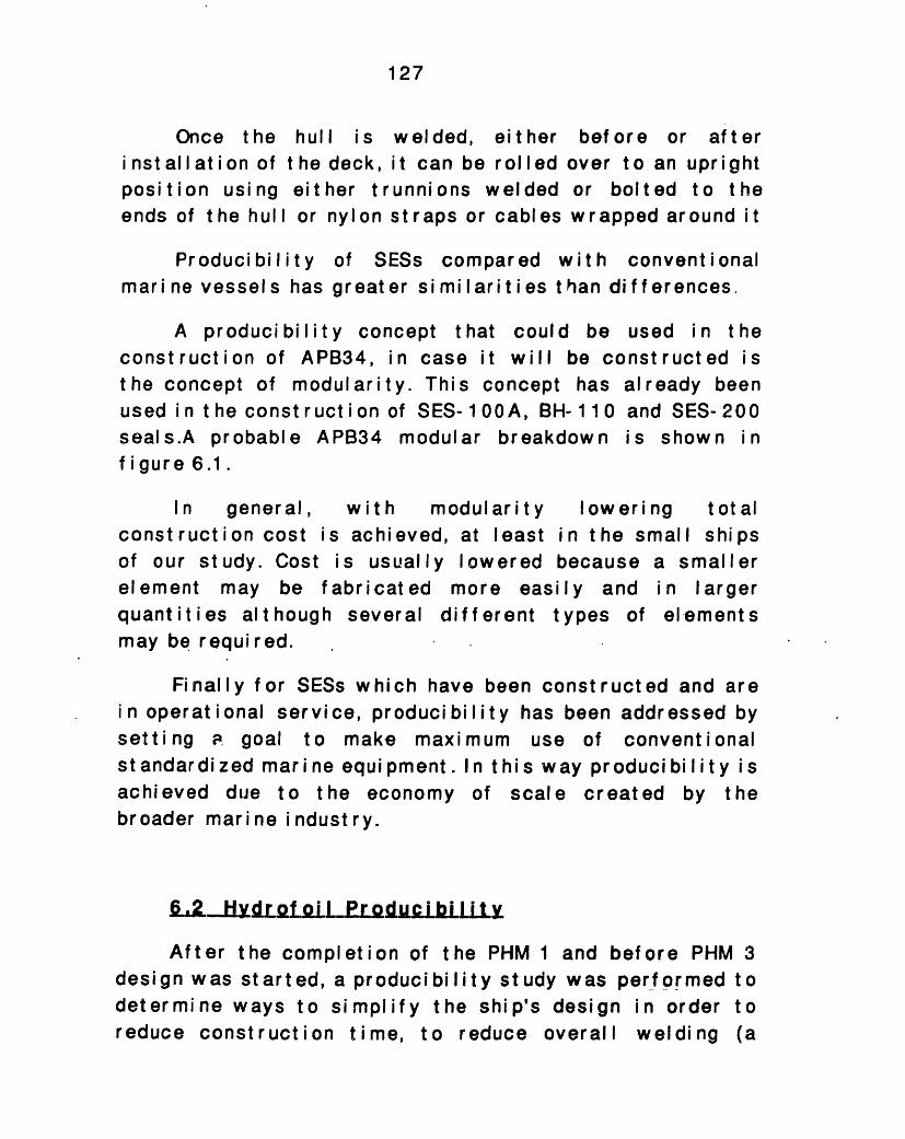
127
Once the hull is welded, eitheri nst all ation of t he deck, it can be rolledposition using either trunnions weldedends of t he hull or nylon st raps or cabl es
before or afterover to an uprightor bolted to thew r apped ar ound i t
Producibility of SESs compared with conventionalmarine vessels has greater similarities t han differences.
A producibility concept that could be used in theconstruction of APB34, in case it will be constructed isthe concept of modularity. This concept has already beenused in the construction of SES-100A, BH- 110 and SES-200seals.A probable APB34 modular breakdown is shown infigure 6.1.
In general,construction cost iof our study. Costelement may be fquantities althoughmay be required.
withs achieveis usual abri cat ec
several
modularity lowering totalid, at least in the small shipsly lowered because a smallerI more easily and in larger
different types of elements
Finally for SESs which have been constructed and arein operational service, producibility has been addressed bysetting goal to make maximum use of conventionalstandardized marine equipment. In this way producibility isachieved due to the economy of scale created by thebroader marine i ndust ry.
L2. HyLQdr ofiil ProduLibiLLit
After the completion ofdesign was started, a producidetermine ways to simplifyreduce construction time, t
the PHM 1 and before PHM 3
bility study was performed tothe ship's design in order too reduce overall welding (a
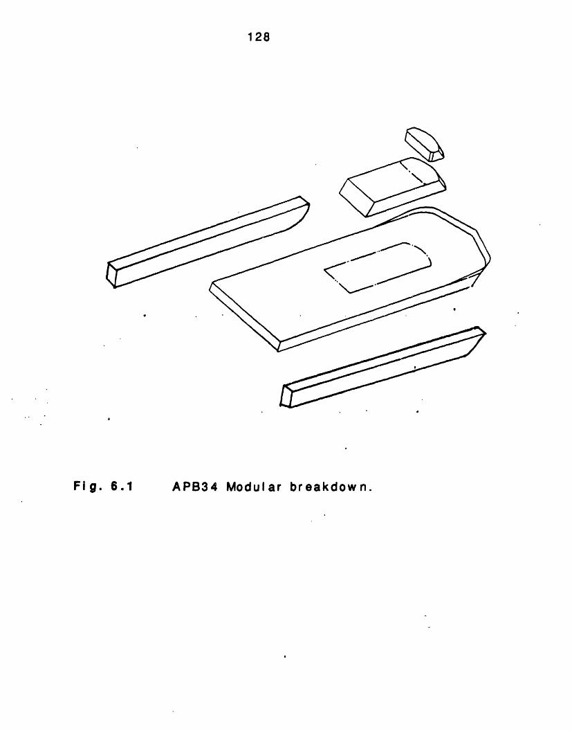
128
APB34 ModularFl 9 61 breakdown.
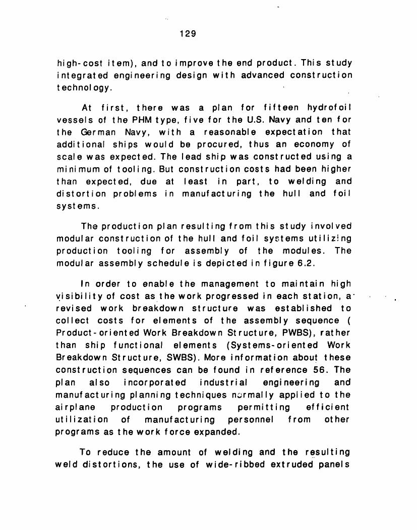
129
high- cost it em), and t o i mprove t he end product. Thi s studyintegrated engineering design with advanced constructiontechnology.
At first, there was a plan for f if teen hydrof oi Ivessels of the PHM type, five for the U.S. Navy and ten forthe German Navy, with a reasonable expectation thatadditional ships would be procured, thus an economy ofscale was expected. The lead ship was constructed using aminimum of tooling. But construction costs had been higherthan expected, due at least in part, to welding anddistortion problems in manufacturing the hull and foilsyst ems.
The product i on plan resul t i ng f rom t hi s st udy i nvol vedmodular construction of the hull and foil systems utilizingproduction tooling for assembly of the modules. Themodular assembly schedule i s depi ct ed i n f i gure 6.2.
In order tovisibility of costrevised work brcollect costs fo
enable the management to maintain highas the work progressed in each station, aeakdown structure was established tor elements of the assembly sequence (
Pr oduct - or i ent ed Wor k Breakdow n St r uct ure, PWBS), r at
than ship functional elements (Systems-oriented WBreakdown Structure, SWBS). More information about thconstruction sequences can be found in reference 56.pl an al so incorporated industrial engineeringmanufact uri ng planning techniques nor mal ly appi i ed toai r pl ane product ion programs permitt ing eff iciutilization of manuf act uri ng personnel from ot
herforkeseTheandtheenther
programs as the work force expanded.
To reduce the amount of welding and the resultingweld distortions, the use of wide-ribbed extruded panels
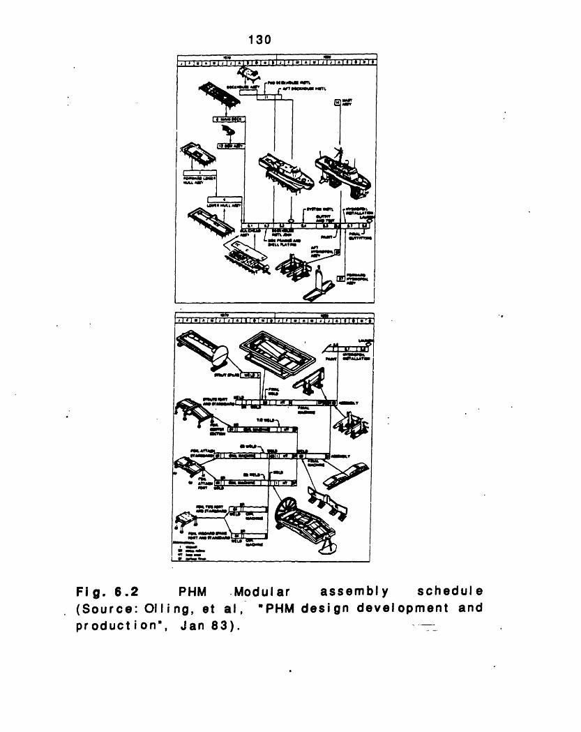
130
t eaMNenl~--rl r ~ " f. '""r EF
1~
u r I
'S i#WV t 011
"e~~~~b _ r~~~I
_4Z3N--:E:
m , jLiIL ~t RA VON
S!-- A
rP
r*
r 0 sonI--=~r
SMA&WO-rm
m7YJmmw
.Modular assembly schedule(Source: Oil ing, et al, 'PHM design development andproduction",
. _ .I . I. I. *I . I I . .
Fig. 6.2 PHM
_ _ __ _ _ ·~~~~~~~~~~~~~~~~I
! j I I I 9 I - I - I . . . I I . � I - . . . . . . I I . . I . . . . . . . I
. 'P I
_
I¢ 1"1
__aufIr__ro_s
.,
Jan 83).
I
4w
CE
131
wherever practical consi der at ions of f abri cation andmaterial usage would permit, was selected.
In the lead ship design, too many parts were used.Also access to welds was difficult. Weld distortion madesubsequent fit-up time consuming. The production designresulted from extensive study of lead ship design andconst ruct i on probl ems.
The foils and struts of the PHM for the lead ship wereconst r uct ed i n a f ai r I y convent i onal manner. Di f f i cul t y w asencountered in maintaining the contours. The underbeads ofmany of the complex tee welds were not accessible forinspect ion or gri nding.
Very early in the operational life of the lead ship,cracks appeared in the skins of the foils. Inspectionindicated that the primary cause of failure was materialfatigue. Although the levels of loads used in the designwere generally correct, the frequency of high loads wasmuch higher: than that previously anticipated. Afterwards,the foils and struts of t he production ships wereredesigned using fatigue criteria, analytical techniquesand design approaches developed for airplane design. Inaddition to satisfying the requirement for fatigueresi stance, t he f oi Il and st rut redesi gn i ncorporat ed desi redproducibility improvements such as fewer individual parts,less weld length and increased mechanized welding.
Producibility concepts arose from the production ofM161 as well. M161's hulls are of 5456-H1ll Aluminumusing 5356 filler rods. Extruded planks with integralstiffeners were used for most of the hull structure. Thisreduced the amount of welding and permitted a largeproportion of welding to be done automatically. Seven
1 32
transverse bulkheads and 33 transverse stiffeners wereused on the design.
6.3 SUMMARY
The producibilhelp the manufactefficiently and witsmall improvementproven conventional
ity concepts discussed in this chapterurer and designer produce the shipsh a lower cost. Ships are designed withs to meet new requirements based onand aerospace technology.
The Product Oriented Breakdown Structure (PWBS)gives the opportunity for continuous improvement, andideas feed-back, per mi t t i ng ef f i ci ent ut i I i zat i on ofpersonnel at all levels of manufacturing process.
133
CHAPTER 7
LESSONS LEARNED
A review of all the previouschapter 7.
chapter is presented
All the vessels oftons in displacement.
our study are between 70Their primary mission
and 250can be
summarized to be the attack and destructionsurf ace shi ps with anti-ship missiles and/ or guns. Theirsecondary missions could include:
(1) Survei Illancepoi nts.
of coast al areas, especially
(2) High technology naval presence.
(3) Special operations which include:
Del iveryspecial force units.
and retrieval of commando-type
Trailing and shadowing of high i nt er estshipping.
Decept i on and decoy of host i le faces.
(4) Quasimilitary operations which may include:
Survei I llance and prot ect i on of f i shi ng and of f -shore oil zones.
Ant ismuggli ng
Search and rescue.
in
of larger
choke
134
L1,1 I AI BLUI EAti DL l MI TATI ONSQF LT HEHu .ELS H M_ A N _M1 L
The principal advantages of the hydrofoil ships (M161and PHM), over the monohull design of our study are:
(1)convent i onearly all
The ability of thenal ship standards,ship environments.
ships whichto operate
are smallefficiently
(2) The attractive ratio of power to displacement inthe 30 to 50 Knot speed range permitting economicaloperation at these higher speeds. In this speed range,hydrofoils are more efficient than the SESs and themonohul I s. Thus f or a gi ven shi p si ze and i nst al I led pow er, ahigher maximum speed may be obtained.
(3) The except i onal sthem a superior platformequipment and weapons wand proficiency.
(4)radicallyf oi I borne
t abi I it y of PHM and M161 makesin which to mount surveillance.hile maintaining crew comfort
Another naval attribute of PHM and M161 isdifferent pressure and acoustic signaturescompared with displacement hulls.
t hei rwhile
These advantages do not come cheaply. Thoughrequiring less power than conventional ships of the samesize and speed, power requirements are still high.Therefore, in common with other high performancesystems, weight of structures, propulsion and auxiliarysystems must be carefully controlled to attain the usefulloadweight fractions necessary for effective militaryships. To obtain the outstanding rough water behaviordemands a foil system with relatively complex strut, foil
byin
135
and flap structures, automatic control systems and high-power hydraulic actuation systems. Therefore, the cost perton of M161 and PHM exceeds that of conventional ships.When appropriately designed for military roles which takeadvantage of the unique operational capabi I i t i es t hehydrofoil offers, PHM and M161 can cost less whenmeasured in dollars or per unit of applicable performancethan CPIC or SPICA II convent i onal ships for t he same role.
The PHM aft foil extends almost 10 feet on either sideof the hull. As ship size increases and foils grow relativeto t he hull and i n act ual di mensi on, practicalconsi derat i ons di ct ate ef f ort s t o I i mi t t he f oi I span.
7.1k2 ATRI LBUTES_AND LMTATIO NS OF APB3 4
(1) Since the full displacement sidehulls of APB34need to be optimized for low-speed hullborne resistance,they are more efficient than most traditional monohullswhose shape must be compromised to be effective at bothlow and moderate speeds.
(2)internalthe ship.
(3)monohul I
shape ofapproach
The full displacementvolume and deck area to
APB34 has greats or the hydrofoil
the center bodyi ng 1 compared to
sidehulls havebecome a useful
enoughpart of
er volumetric efficiency than thes. This is due to the rectangularwhich has a block coefficient
0.7 for t he ot her vessels.
(4) APB's deck areas follow the same trends asillustrated for volumes.
I _ _ ___ __ _ _ _ _ _ _ _ __ ___ _ ___ _________ ~_ _~-- -- m
136
(5) The forward draft of APB34 is shallow enough toallow beaching. The low draft allows APB34 to enterharbors and dock at piers too shallow for CPIC, SPICA II orthe hydrofoils. The shallow on-cushion draft is less thanthe running depth of torpedoes making APB34 immune tocontact torpedo explosions. The small percentage of thehull in the water significantly reduces the effects of anunderwater explosion. The great shock attenuation, due tothe small amount of the ship in contract with the waterand its shallow draft, means that the design strength builtinto the APB34 for traditional seakeeping loads is morethan adequate to handle these shock loads.
(6) On cstability paramthe same high iiand does not rweight balance.
ushi oreter fnitialequi re
1
orst
f
stability is the most criticalAPB34. When hullborne, APB34 has
ability associated with catamarans,uel compensating systems or dead
(7) Thecompar.t ment at iallows APB34monohul I s,andsubsystems are
ongitudinalon. required. for stto sustain damage
hydrofoils and remaioperabl e.
and transverserU ctural · efficiencyin excess of the
n operable if key
(8) When on cushi on t he w et t ed surf ace of t he APB34is drastically reduced which permits high speed operat ionswit h reasonable power.
APB34 and SESs generally need improvement in theircushion pressure control systems. An improvement willreduce motion accelerations, thus reduce sea-sickness inhigh frequencies.
137
7. 1 3 ATTRBIUTESAND L MIIL TATI E_ HEMQNJiuLL :cPIl Cr A. L
The monohull crafttype military vesseltechnologic?,l view point
of the studyhave manysince:
and any planing-hulladvantages from a
(1 ) They do not have serious navigational draftlimitations.
(2) They have goodprimarilly to the use ofstabilizers, which furtherdisplacement speed range, operat ion at these speeds.
(4) They canwater operationalsea conditions.
inherhard
reduceI ow i n
retain a largespeed capabilit
ent rol Idumping, duechine. CPIC uses fin
the roll motions in theg comfortable long-term
e portion of their calmy in moderate to severe
(5) The construction of theirshipyard practice and does notfabrication techniques. Most of thtechnology has been used for years,design problems have been solved for
hul I canrequire aie requi redand all thethese ship,
use normalrcraft- typestructuralstructural
The limitations that follow ail these attributes,be summarized in the following lines.
(1) The lift to drag ratiocompared to hydrofoils and SESs of
wilthe
(2) TheI never behydrofoil
at high speedsthe same size.
is less
seakeeping performance in high sea statesthe same with the seakeeping performance ofcraft.
can
138
LZ M A RE.C.MMEN. ET[ H U RU.T J LLUThe number of ships investigated has been limited. A
larger data base is required to verify the results of thischapt er.
The nonavailability of classified and proprietary datawas the main reason for error in this investigation. Somespecific areas require more intensive study. Specificallythese are seakeepi ng, and maneuverability. This two issueswere discussed only generally i n our study.
Another area for extensive study is combat capabilityassessment. The benefits of various trade-offs, and theirimpact on the total ship system, should be evaluated andmade available to designers.
139
BI BLI OGRAPHY
NAVAL INSTITUTE PROCEEDINGSG. G. Halvorson, "The role of High speed ships in theNavy", Jan 79.N. Friedman, "Speed in modern warships", May 79.B. Linder, "Pegasus: Winner or also run?", Sept 81.T. McKearney, "The offensive surface ship", Dec 83K. Thompson, "Speed is more than moving swiftly",
83.
HIGH SPEED SURFACE CRAFT6. J. Pi ng- Zhong et al, "A paround bil ge displacement hul ls7. D. Oiling et al, "Patrol coPHM- design, development and I
rametric study of high speed", Sept 80.mbatant missile (hydrofoil)-product ion", Jan- Feb 81.
COMBAT CRAFT8. C Dawson, "Power for fast attack craft", Sept
AMERI CAN INSTITUTE OF AERONAUTI CSASTRONAUTI CS9. "PHM hu I producibility design", 76.
MARITI ME DEFENCE10. "An SES patrol craft",11. "Small Naval vessels",
Aug 83.Mar 85.
12. J. Watson Noah, Inc,vehi cl es"(FR- 1 220- U.S.N.),
"Cost analFeb 78
ysis of advanced Naval
US1.U.S.
2.3.4.5.Nov
83.
AND
140
I NTERNATI OMNAL DEFENCE REV I EW13. W. Cassedy, "A procedure to evaluate the feasibilityof Naval ship designs", May 77.14. "RINA Symposium on Small Fast warships and patrolvessels", Oct 78.15. "Naval ship design concepts for the 1990's", Aug 81.1 6. "FAC hull f or ms. A comparat i ve st udy of t wo di ff erentconcepts", Jul 81.17. J. Kehoe, "Small Combatants. The operators choice",Jun 87.18. C. Dawson, "Unconventional hull forms for smallwarships", Jun 87.19. C. Dawson, "Survival of small warship", Jun 87.
DEPARTMENT OF THE NAVY. NAVAL SEA SYSTEMSCOMMAND20. "U.S. Navy Space Classification manual", Nov 83.21 "U.S. Navy Standard Ship Work Breakdown Structure",Mar 73, revised Apr 81.22. "Data book for boats and craft of t he US Navy"
MIT THESIS23. J. Grostick, "A comparative analysis of Navalhydrofoil and displacement ship design", Jun 75.24. J. Schnellenberger, "Comparative assessment of navalship propulsion system operability. High performance vsconventional designs", Jun 77.25. P. Sullivan, "A comparative analysis of smallcombatant ships", Jun 80.26. U. Rowley, "Naval ship design, methodology forcomputer supported Naval ship design", Jun 85.
141
SNAME27. Benson,design of High28. Sorkin, etstructural desi29. T. Pruett,30. Allison,Mar 78.335.31.pred32.resi33.Guar34.outf
"Parametric analysis for the conceptualperformance ship", Jan 75.
al, "General considerations regarding thegn of high performance ships", Jul 75."On the wave resistance of SES", 75"Propellers for high performance crafts",
Kelly, et al,liction", Mar 79
Hsi ung, "Optstance", Jun 81Tozzi,.."Advanc
d", Dec 83.Matt hews,et al
i tt i ng concepts"
"Subcavitating hydrofoil lift and drag
imal ship forms for minimum wave
ed Mari ne vehi cl es for t he Coast
", Designing for propulsion Advanced, Dec 84.
. Svensonthe power
But I er,Bost, et
. Kazek,85.
. Smith,
, et al, "Experiencerange 140 to 10000"Marine propulsion ial, "Human f..actors"A comparison of
with water j et propulsionKW", Feb 85.n small craft", Feb 85.in Naval ship design", 85.offshore patrol vessels",
"The aerodynamics of high speed boats", Oct
SNAME TRANSACTIONS40. P Kaplan, et al, "Dynamics and hydrodynamics of SES",81.41. J Block, et al, "High speed displacement shipsystematic series hull forms seakeeping characteristics",84.
TRANSACTIONS OF RINA42. Vol 124, "A family of warships", 82.
35in363738Jar3985
142
43. J. Kelly, "Efficient, practical, higher speed patrolboats based on SES technology", Jun 78.
ASNE44. J. Kehoe, et al, "Comparative analysis of US andforeign ship design practices", Oct 78.
BOOKS45. "Janes Fight i ng ships".46. Handel, "Water , air interface vehicles".47. "RINA Proceedings of the symposium on small fastwarships and security vessels", 82.48. "Warship 86. International symposium on coastaldefence and assault vessels", Vol 1, Ill.49. "High speed surface craft conference", May 1983.50. "Rough sea capabilities and ship size. A parametricinvestigation into the small warship area".51. "International naval technology exposition", 82.52. "International naval technology exposition", 78.53. David Taylor Naval ship research and developmentcenter, "Workshop on development on hull form design",Apr 79.54. "Technical evaluation of the SES-200 high length tobeam "ratio SES", May 84.55. "ASSET, Hydrofoil Design Manual", Revised Apr 86.56. R. Stroch, et al, "Ship Production", 88.57. P. Comstoc, et al, SNAME, "Principles of NavalArchitecture", 83.58. Boeing, "Hydrofoil craft structural criteria", Apr 72.
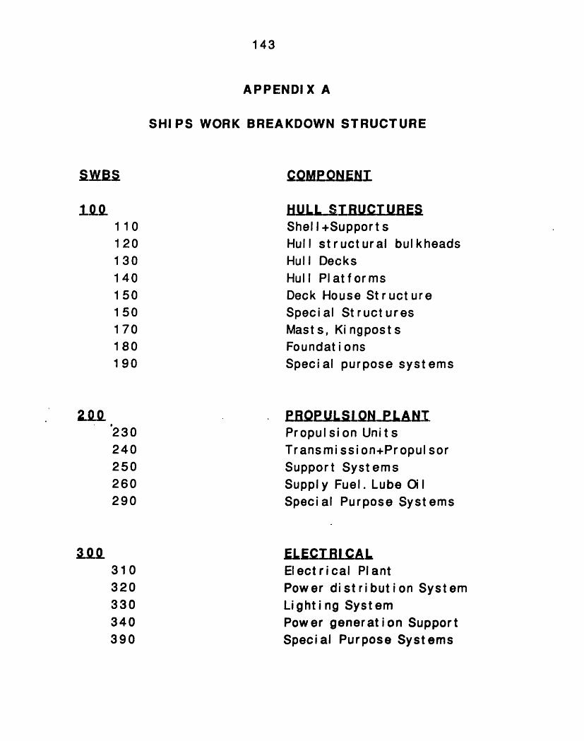
143
APPENDIX A
SHIPS WORK BREAKDOWN STRUCTURE
cQMPQ ElI
UL ST RUCT UR ESShel l +Support sHull structural bulkheadsHull DecksHull PlatformsDeck House St ruct ureSpecial StructuresMasts, Ki ngpostsFoundat i onsSpecial purpose systems
EPOPUL LONL LANi
Propulsion UnitsTransmission+Propul sorSupport SystemsSupply Fuel. Lube OilSpecial Purpose Systems
EL IT R1ALElectrical PlantPower dist ri but i on SystemLighting SystemPower generation SupportSpecial Purpose Systems
1101201301401 50
150170180190
230240250260290
a2Q310320330340390
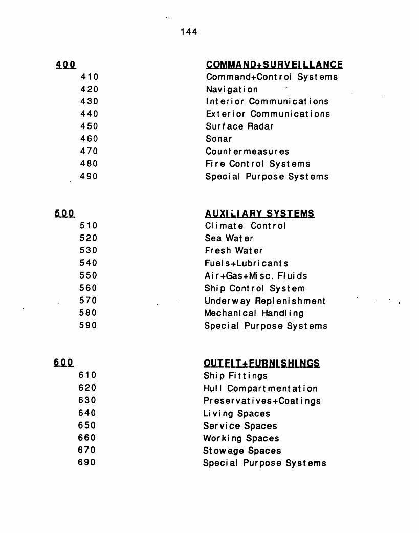
144
·~LQMMA1 BY+ S ELLLAKE410 Command+Cont rol Systems420 Navi gat i on430 Interior Communications440 Exterior Communications450 Surface Radar460 Sonar470 Count er meas ur es480 Fire Control Systems490 Special Purpose Systems
AUXLARY SYST EMS510 Climate Control520 Sea Water530 Fresh Water540 Fuel s+Lubr i cant s550 Ai r+Gas+Misc. Fluids560 Ship Control System570 Underway Replenishment580 Mechanical Handling590 Special Purpose Systems
UIFI T + FURNI SHI NGS610 Ship Fittings620 Hull Compart mentat i on630 Preservat i ves+Coat i ngs640 Li vi ng Spaces650 Service Spaces660 Wor king Spaces670 Stowage Spaces690 Special Purpose Systems
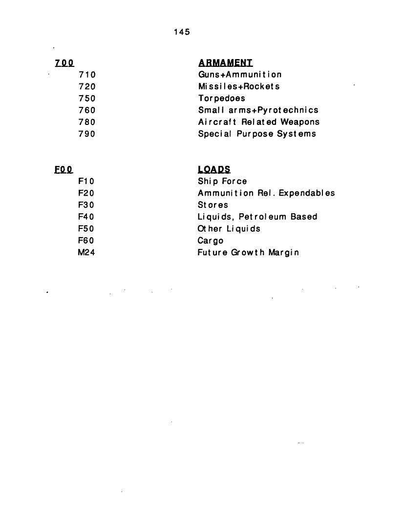
145
Z.g. ABMAMENT710 Guns+Ammuni t i on720 Mi ssi I es+Rocket s750 Torpedoes760 Small arms+Pyrotechnics780 Aircraft Related Weapons790 Special Purpose Systems
EOOg LQOAIF10 Ship ForceF20 Ammunit ion Rel. ExpendablesF30 StoresF40 Liquids, Pet rol eum BasedF50 Ot her Li qui dsF60 CargoM24 Future Growth Margin
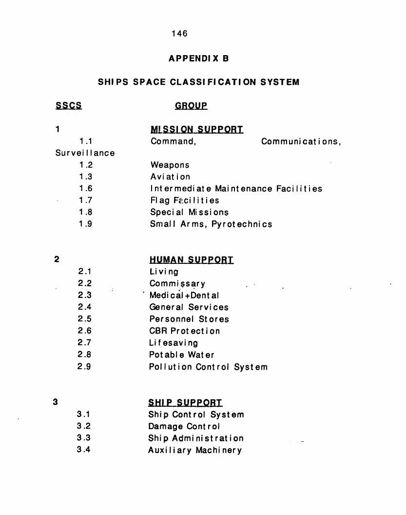
146
APPENDIX B
SHIPS SPACE CLASSIFICATION SYSTEM
1
1 .1
Surveil lance1 .2
1 .3
1 .6
1.71 .8
1 .9
22.12.22.32.42.52.62.72.82.9
33.13.23.33.4
ML5SiLQN _SUPPORTCommand, Communi cat i ons,
WeaponsAvi at i onIntermediate Maintenance FacilitiesFlag Fci I i tiesSpecial MissionsSmall Arms, Pyrotechnics
UMANUP OILi vi ngCommissaryMedi cal +Dent alGeneral ServicesPersonnel StoresCBR ProtectionLi f esavi ngPotable WaterPollution Control System
SkILE ._S.UEIMShip Control SystemDamage ControlShip Admi nist rat ionAuxi I i ary Machi nery
147
3.5 El ect r i cal3.6 Ship Maintenance3.7 Storerooms, Issue Rooms3.8 Access3.9 Tankage
4 SHL PLMQRI LLT Y SYSTEM4.1 Propulsion System
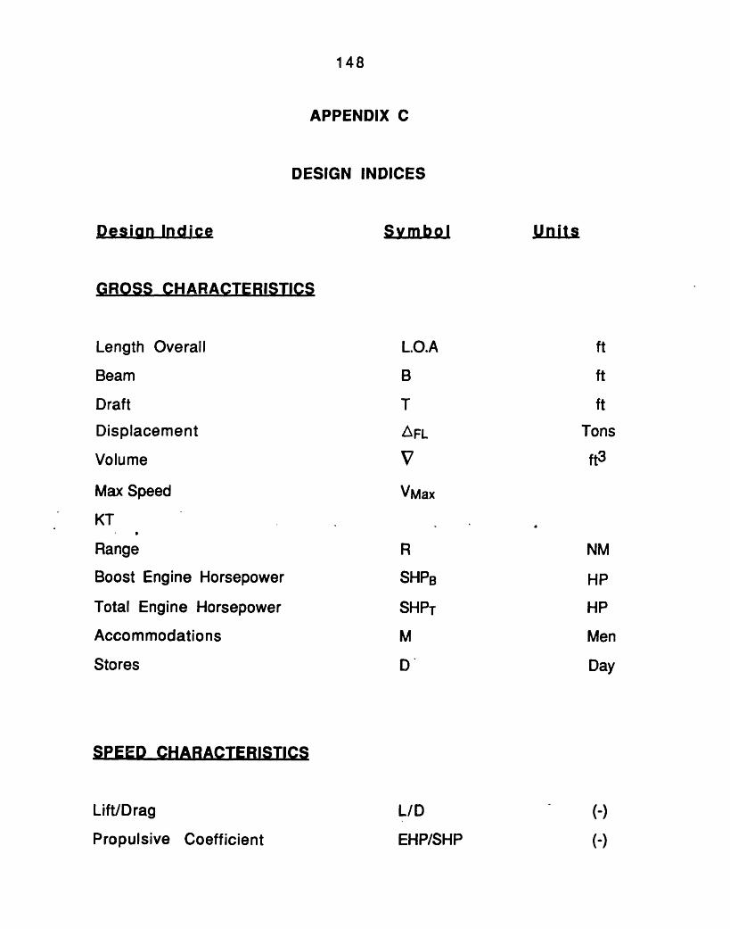
148
APPENDIX C
DESIGN INDICES
Desin Indice Sym bo I U ts
GROSS CHARACTERISTICS
Length Overall L.O.A ft
Beam B ft
Draft T ft
Displacement AFL Tons
Volume V ft3
Max Speed VMax
KT
Range R NM
Boost Engine Horsepower SHPB HP
Total Engine Horsepower SHPT HP
Accommodations M Men
Stores D' Day
SPEED CHARACTERISTICS
Lift/Drag L/D (-)
Propulsive Coefficient EHP/SHP (-)
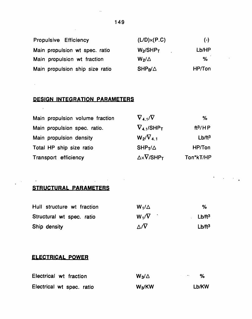
149
Propulsive Efficiency
Main propulsion wt spec. ratio
Main propulsion wt fraction
Main propulsion ship size ratio
(UD)x(P.C)
W2/SHPT
W2/L
SHPB/A
DESIGN INTEGRATION PARAMETERS
Main propulsion volume fraction
Main propulsion spec. ratio.
Main propulsion density
Total HP ship size ratio
Transport efficiency
V 4.1/V
V4.1/SHPT
W2/V4.1
SHPT/A
AxV/SHPT
ft3 / H P
Lb/ft3
HP/Ton
Ton*kT/HP
STRUCTURAL PARAMETERS
Hull structure wt fraction
Structural wt spec. ratio
Ship density
ELECTRICAL POWER
Electrical wt fraction
Electrical wt spec. ratio
(-)
Lb/HP
HP/Ton
W1/V
AL/V
Lb/ft3
Lb/ft3Lb/ft3
W3/A
W3/KW Lb/KW
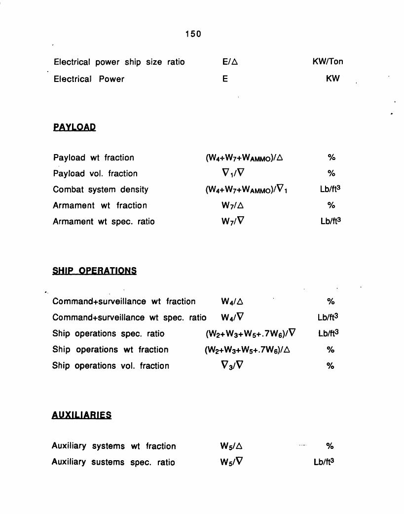
150
Electrical power ship size ratio
Electrical Power
Payload wt fraction
Payload vol. fraction
Combat system density
Armament wt fraction
Armament wt spec. ratio
E/EA KW/Ton
E KW
(W4+W7+WAMMO)/A
V1/v
(W4+W7+WAMMO)/V 1
W7/A
W7/V
SHIP OPERATIONS
Command+surveillance wt fraction W 4 /A
Command+surveillance wt spec. ratio W4/V
Ship operations spec. ratio (W2+W3+W5+.7W 6)/V
Ship operations wt fraction (W2+W3+W5+.7W 6)/A
Ship operations vol. fraction V 3/V
Auxiliary systems wt fraction
Auxiliary sustems spec. ratio
W/A
W5/V
Lb/ft3
Lb/ft3Lb/ft3
Lb/ft3
Lb/ft 3
%
%
Lb/ft3
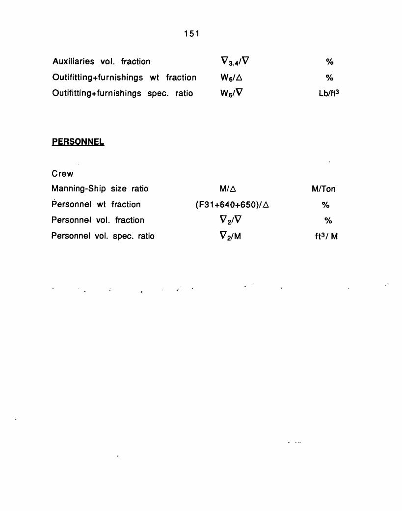
151
Auxiliaries vol. fraction
Outifitting+furnishings wt fraction
Outifitting+furnishings spec. ratio
PERSONNEL
Crew
Manning-Ship size ratio
Personnel wt fraction
Personnel vol. fraction
Personnel vol. spec. ratio
M/E
(F31+640+650)/A
V2/V
V2/M
V3 .4/V
W6/AL
Ws/V Lb/ft3
M/Ton
ft/ M
ft3/ M


![Factors for GVC participation in sub-Saharan Africa€¦ · /lwhudwxuh uhylhz -rqhv dqg .lhu]nrzvnl irupxodwhg dq dqdo\wlfdo iudphzrun iudjphqwdwlrq wkhru\ lq zklfk orzhu surgxfwlrq](https://img.pdfslide.us/doc/110x75/5f0f3a507e708231d4431eb6/factors-for-gvc-participation-in-sub-saharan-africa-lwhudwxuh-uhylhz-rqhv-dqg.jpg)