Embed Size (px)
Citation preview
Naval Research LaboratoryPlasma Physics DivisionWashington, DC 20375
11th HAPL MeetingNaval Research Laboratory
Washington, DC March 3-4, 2005
Work supported by DOE/NNSA/DP
KrF lasers
NRLJ. SethianM. MyersJ. GiulianiR. LehmbergS. Obenschain
Commonwealth TechF. HegelerM. Friedman
T. Albert
SAIC M. Wolford
RSIP. Burns
TITAN S. Swanekamp
MRC Albuquerque D. Rose Titan PSD, Inc
D. Weidenheimer
Opti Switch, Inc D. Giorgi
The goal for the Electra KrF Laser Program is to develop the technologies that can meet fusion energy requirements
for durability, efficiency, and cost
• Meet target physics and IFE requirements for laser beam uniformity and wavelength
• Wall plug efficiency > 6% (preferably > 7%)
• Operate at repetition rates up to 5 Hz
• Produce 400- 700 J of laser light/shot per pulse
• Run continuously for tens of thousands of shots
• Technologies developed must scale to IFE size system
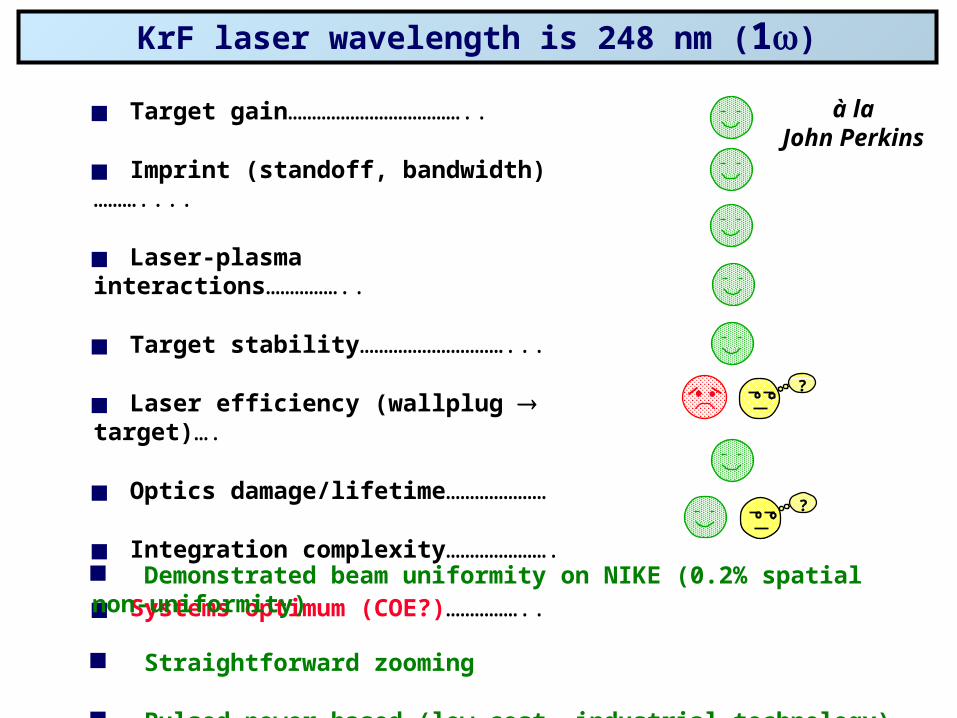
KrF laser wavelength is 248 nm (1)
Target gain………………………………..
Imprint (standoff, bandwidth)………....
Laser-plasma interactions……………..
Target stability…………………………...
Laser efficiency (wallplug target)….
Optics damage/lifetime…………………
Integration complexity………………….
Systems optimum (COE?)……………..
?
?
Demonstrated beam uniformity on NIKE (0.2% spatial non-uniformity)
Straightforward zooming
Pulsed power based (low cost, industrial technology)
à laJohn Perkins
Electra title page
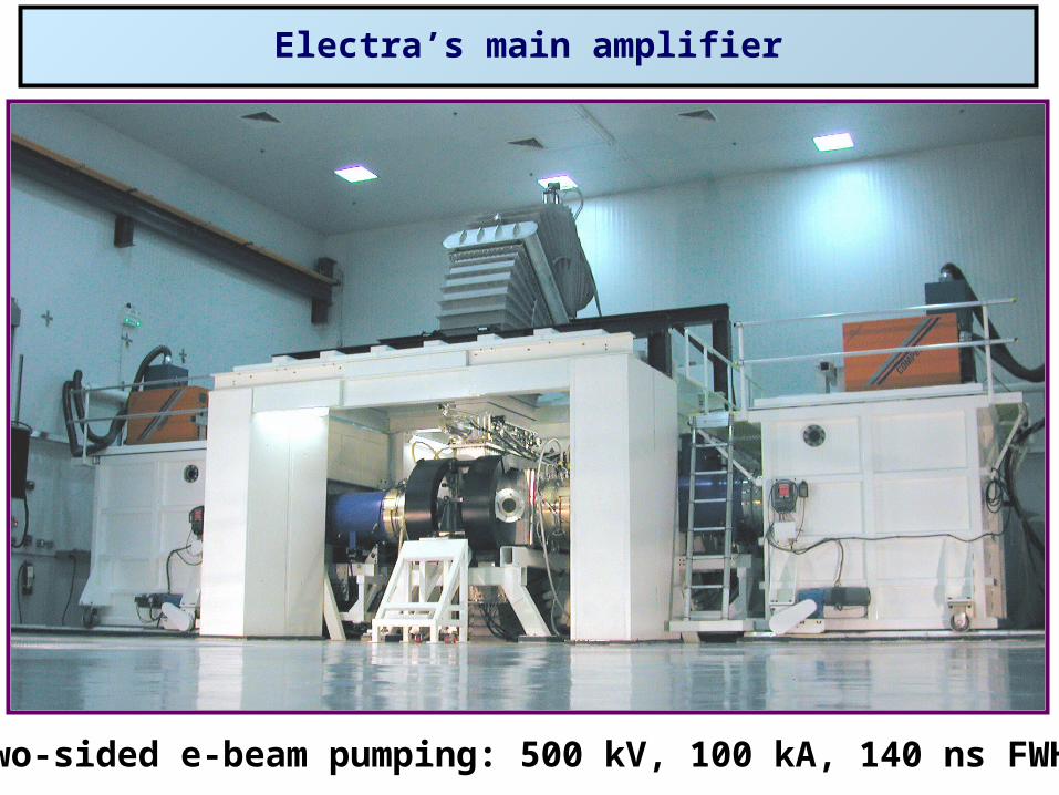
Electra’s main amplifier
Two-sided e-beam pumping: 500 kV, 100 kA, 140 ns FWHM
Pulsedpowersystem
Pulsedforming
line Diode
Laser gas recirculator
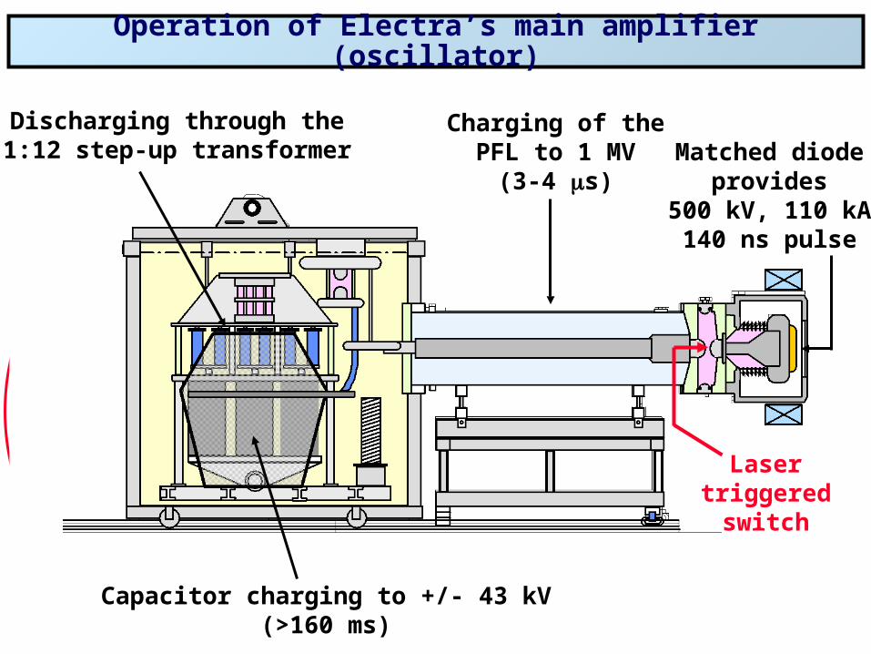
Operation of Electra’s main amplifier (oscillator)
Capacitor charging to +/- 43 kV(>160 ms)
Discharging through the1:12 step-up transformer
Charging of thePFL to 1 MV
(3-4 s)
Lasertriggered
switch
Matched diodeprovides
500 kV, 110 kA140 ns pulse
Diode
Magnet
Diode
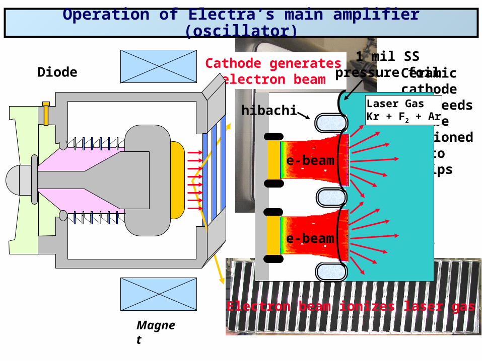
Operation of Electra’s main amplifier (oscillator)
Velvet strip cathode
Ceramiccathode
still needsto be
partitionedinto
strips
Cathode generateselectron beam
e-beam
Laser GasKr + F2 + Ar
1 mil SSpressure foil
e-beam
e-beam
Electron beam ionizes laser gas
hibachi
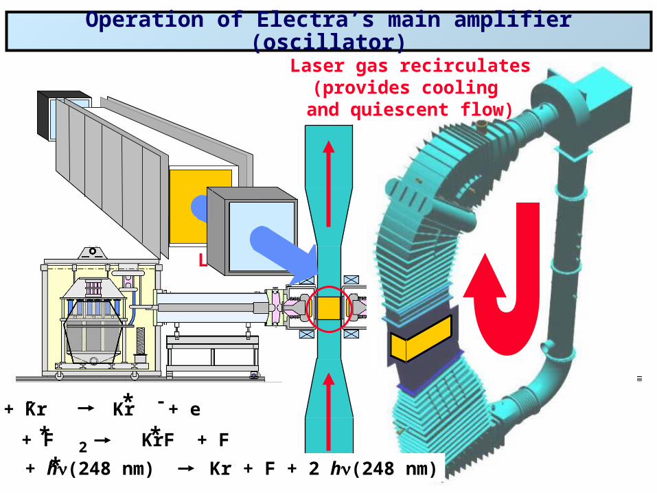
Operation of Electra’s main amplifier (oscillator)
Laser cell
Laser gas recirculates(provides cooling
and quiescent flow)
e + Kr Kr + e
Kr + F KrF + F
KrF + h(248 nm) Kr + F + 2 h(248 nm)2
*- -
**
*
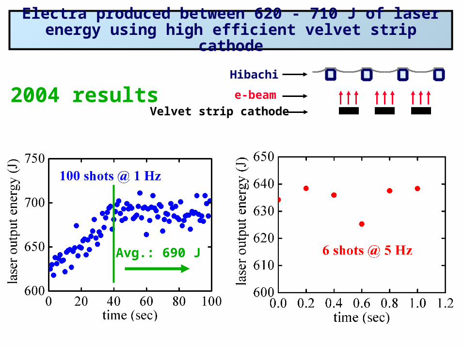
Electra produced between 620 - 710 J of laser energy using high efficient velvet strip cathode
Avg.: 690 J
Velvet strip cathode
e-beam
Hibachi
2004 results

intrinsic eff.: 9.7%
Electra’s oscillator achieved an intrinsic efficiency of 9.7% ...expect ~11% as an amplifier
As an IFE amplifier: KrF grade windows with AR coatingAmplification from input laser
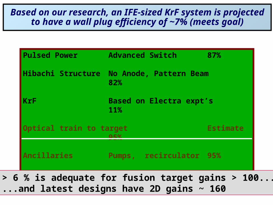
Pulsed Power Advanced Switch 87%
Hibachi Structure No Anode, Pattern Beam 82%
KrF Based on Electra expt’s 11%
Optical train to target Estimate 95%
Ancillaries Pumps, recirculator 95%
Global efficiency 7.1%
> 6 % is adequate for fusion target gains > 100......and latest designs have 2D gains ~ 160
Based on our research, an IFE-sized KrF system is projected to have a wall plug efficiency of ~7% (meets goal)
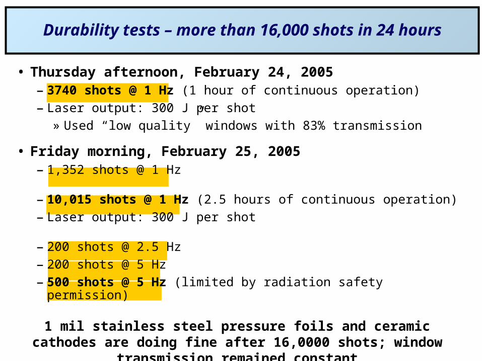
Durability tests – more than 16,000 shots in 24 hours
• Thursday afternoon, February 24, 2005– 3740 shots @ 1 Hz (1 hour of continuous operation)
– Laser output: 300 J per shot» Used “low quality” windows with 83% transmission
• Friday morning, February 25, 2005– 1,352 shots @ 1 Hz
– 10,015 shots @ 1 Hz (2.5 hours of continuous operation)
– Laser output: 300 J per shot
– 200 shots @ 2.5 Hz
– 200 shots @ 5 Hz
– 500 shots @ 5 Hz (limited by radiation safety permission)
1 mil stainless steel pressure foils and ceramic cathodes are doing fine after 16,0000 shots; window transmission remained constant
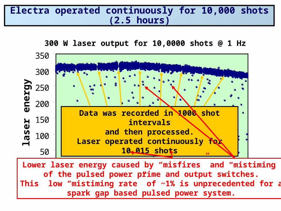
Electra operated continuously for 10,000 shots (2.5 hours)
0
50
100
150
200
250
300
350
0 2000 4000 6000 8000 10000
shot number
lase
r en
erg
y (J
)
300 W laser output for 10,0000 shots @ 1 Hz
Data was recorded in 1000 shot intervalsand then processed.
Laser operated continuously for 10,015 shots
Lower laser energy caused by “misfires” and “mistiming”of the pulsed power prime and output switches.
This low “mistiming rate” of ~1% is unprecedented for aspark gap based pulsed power system.
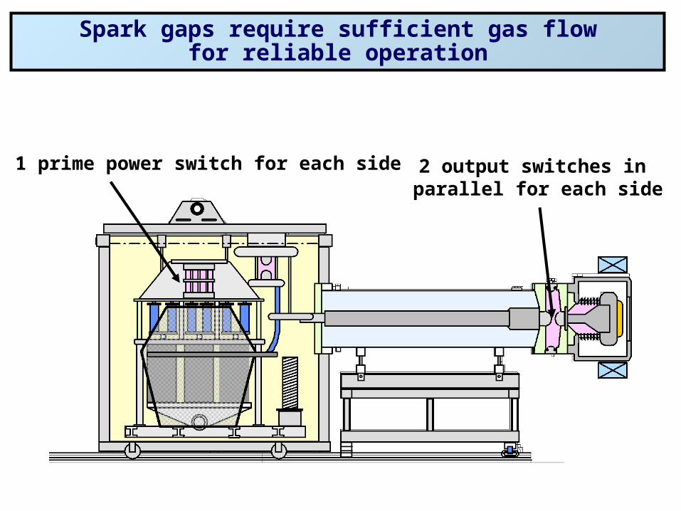
Spark gaps require sufficient gas flowfor reliable operation
1 prime power switch for each side 2 output switches in parallel for each side
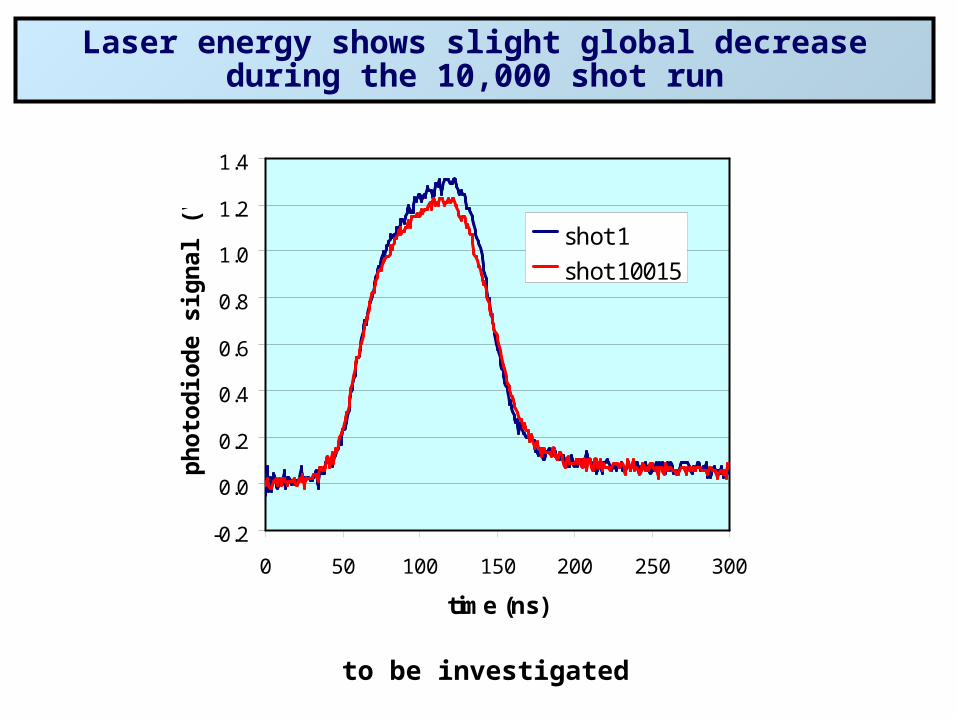
-0.2
0.0
0.2
0.4
0.6
0.8
1.0
1.2
1.4
0 50 100 150 200 250 300
time (ns)
ph
oto
dio
de
sig
nal
(V
) shot 1
shot 10015
Laser energy shows slight global decrease during the 10,000 shot run
to be investigated
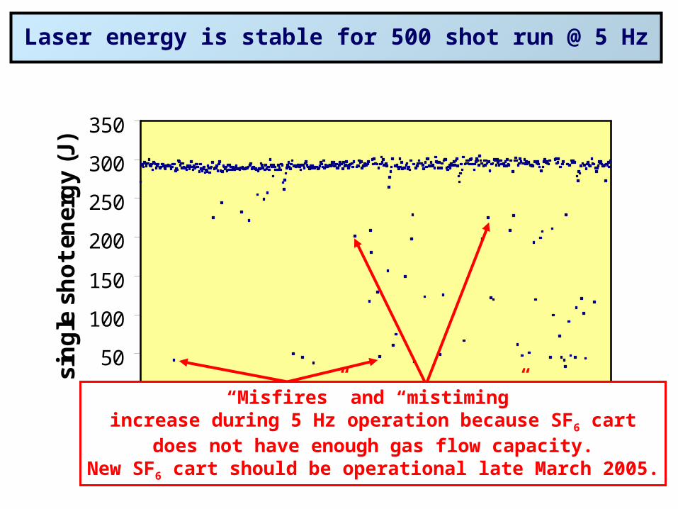
0
50
100
150
200
250
300
350
0 100 200 300 400 500
shot number
sin
gle
sh
ot
ener
gy
(J)
Laser energy is stable for 500 shot run @ 5 Hz
“Misfires” and “mistiming”increase during 5 Hz operation because SF6 cart
does not have enough gas flow capacity.New SF6 cart should be operational late March 2005.
Last major challenge for the KrF laser system is durability.We are closing in on three technologies to address this
1. Foil durability: Primarily an issue of thermal management
3. Pulsed power: Achievable with new advanced solid state switch
2. Cathodes: Demonstrate patterned emission from our durable ceramic cathode leading to high efficiency
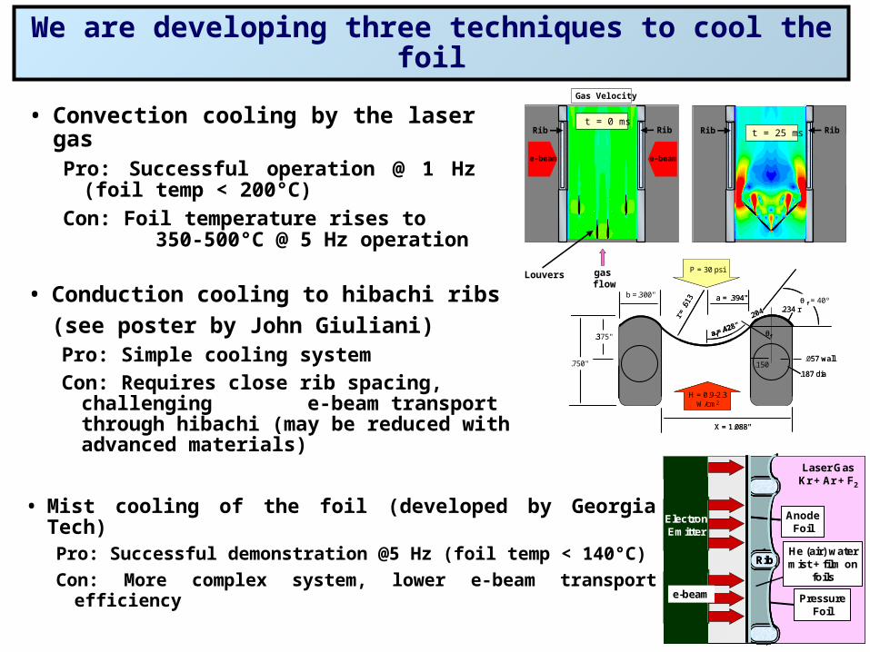
We are developing three techniques to cool the foil
• Convection cooling by the laser gasPro: Successful operation @ 1 Hz (foil
temp < 200°C)
Con: Foil temperature rises to 350-500°C @ 5 Hz operation
Foils
Rib Ribt = 0 ms
e-beam e-beam
gasflow
Louvers
Gas Velocity
t = 25 msFoils
Rib Ribt = 0 ms
e-beam e-beam
t = 75 mst = 125 mst = 0 ms(200 ms)
e-beam e-beam
t = 25 ms
• Mist cooling of the foil (developed by Georgia Tech)Pro: Successful demonstration @5 Hz (foil temp < 140°C)
Con: More complex system, lower e-beam transport efficiency
ElectronEmitter
RibRib
PressureFoil
e-beam
Laser GasKr + Ar + F2
AnodeFoil
He (air) watermist + film on
foils
ElectronEmitter
RibRib
PressureFoil
e-beam
Laser GasKr + Ar + F2
AnodeFoil
AnodeFoil
He (air) watermist + film on
foils
• Conduction cooling to hibachi ribs
(see poster by John Giuliani)Pro: Simple cooling system
Con: Requires close rib spacing, challenging e-beam transport through hibachi (may be reduced with advanced materials)
b =.300" a = .394"
X = 1.088"
P = 30 psi
H = 0.9-2.3W/cm2
.204
a f=.428"
.750"
.375"
f = 40º
r = .6
13
.187 dia
.234 r
f
.150.057 wall
b =.300" a = .394"
X = 1.088"
P = 30 psi
H = 0.9-2.3W/cm2
.204
a f=.428"
.750"
.375"
f = 40º
r = .6
13
.187 dia
.234 r
f
.150.057 wall
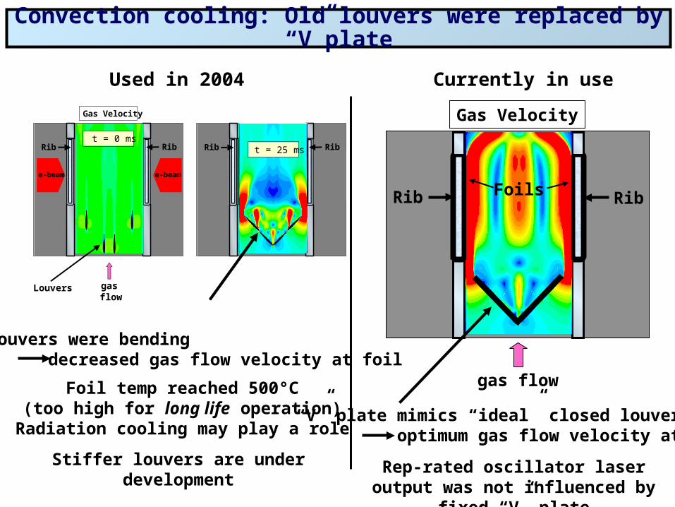
Convection cooling: Old louvers were replaced by “V”plate
Foils
Rib Ribt = 0 ms
e-beam e-beam
gasflow
Louvers
Gas Velocity
t = 25 msFoils
Rib Ribt = 0 ms
e-beam e-beam
t = 75 mst = 125 mst = 0 ms(200 ms)
e-beam e-beam
t = 25 ms
Old louvers were bending decreased gas flow velocity at foil
Foil temp reached 500°C(too high for long life operation)
Radiation cooling may play a role
Used in 2004
Stiffer louvers are under development
Currently in use
“V” plate mimics “ideal” closed louvers optimum gas flow velocity at foil
Rep-rated oscillator laser output was not influenced by fixed “V” plate
gas flow
Rib Rib
Gas Velocity
Foils
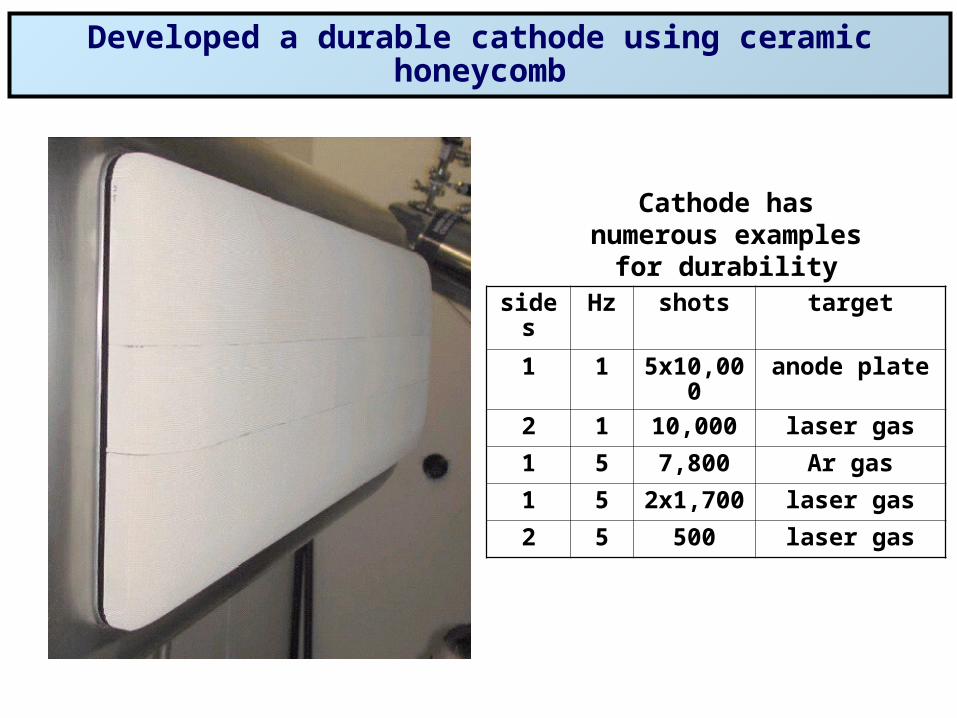
Developed a durable cathode using ceramic honeycomb
Cathode has numerous examples for durability
sides Hz shots target
1 1 5x10,000 anode plate
2 1 10,000 laser gas
1 5 7,800 Ar gas
1 5 2x1,700 laser gas
2 5 500 laser gas
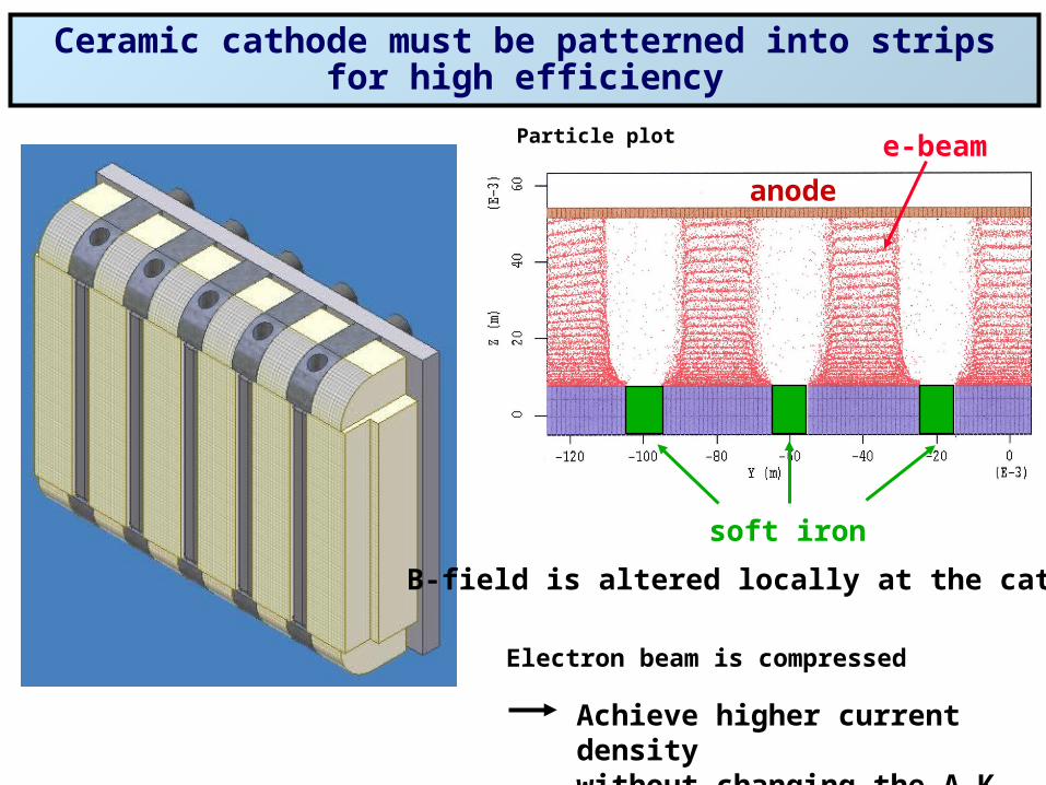
Ceramic cathode must be patterned into strips for high efficiency
soft iron
e-beam
anode
Electron beam is compressed
Particle plot
Achieve higher current densitywithout changing the A-K gap
B-field is altered locally at the cathode
p
n+
n-
n++
p++
Diode Laser
D Laser
SiliconThyrsitor
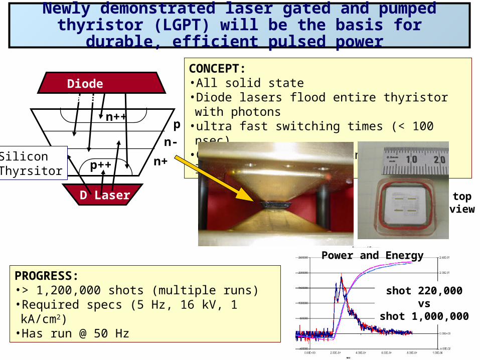
CONCEPT:• All solid state• Diode lasers flood entire thyristor with photons• ultra fast switching times (< 100 nsec)• Continuous laser pumping reduces losses
PROGRESS:• > 1,200,000 shots (multiple runs)• Required specs (5 Hz, 16 kV, 1 kA/cm2)• Has run @ 50 Hz
shot 220,000vs
shot 1,000,000
topview
Newly demonstrated laser gated and pumped thyristor (LGPT) will be the basis for durable, efficient pulsed power
Power and Energy
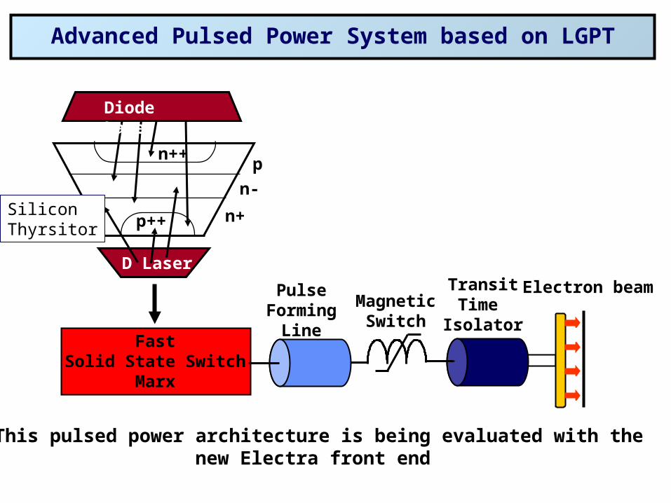
Advanced Pulsed Power System based on LGPT
Electron beam
FastSolid State Switch
Marx
PulseForming
Line
MagneticSwitch
TransitTime
Isolator
This pulsed power architecture is being evaluated with thenew Electra front end
p
n+
n-
n++
p++
Diode Laser
D Laser
SiliconThyrsitor
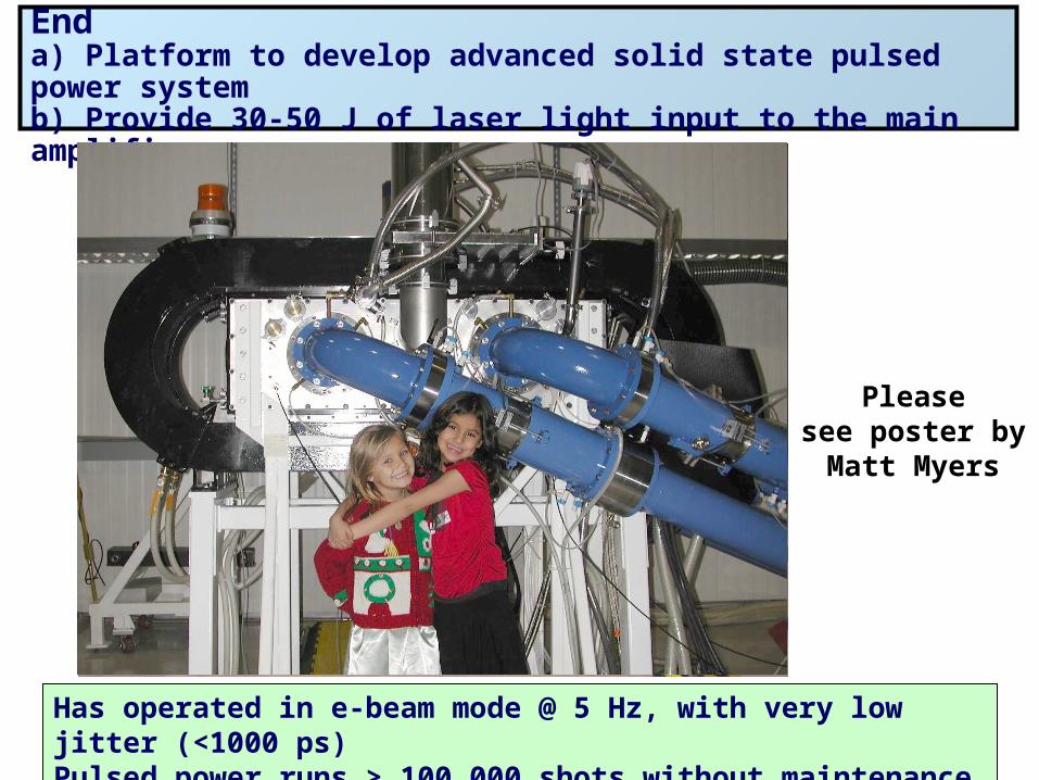
The Electra Front Enda) Platform to develop advanced solid state pulsed power systemb) Provide 30-50 J of laser light input to the main amplifier
Has operated in e-beam mode @ 5 Hz, with very low jitter (<1000 ps)Pulsed power runs > 100,000 shots without maintenance
Pleasesee poster by
Matt Myers
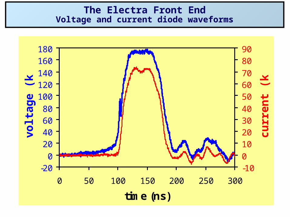
The Electra Front EndVoltage and current diode waveforms
-200
20406080
100120140
160180
0 50 100 150 200 250 300
time (ns)
volt
age
(kV
)
-100
10203040
506070
8090
curr
ent
(kA
)
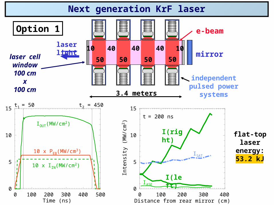
Next generation KrF laser
IOUT(MW/cm2)
10 x IIN(MW/cm2)
10 x PEB(MW/cm3)
I(right)
I(left)IASE
ISAT
Inte
nsity
(M
W/c
m2 )
Distance from rear mirror (cm)
15
10
5
0
t1 = 50 t2 = 450
Time (ns)2000 400 500100 300 2000 400100 300
15
10
5
0
t = 200 ns
e-beam
50 50 50 50mirror
3.4 meters
10 40 40 1040
Option 1
laser cell window100 cm
x100 cm
independentpulsed power
systems
laser light
flat-toplaser
energy:53.2 kJ
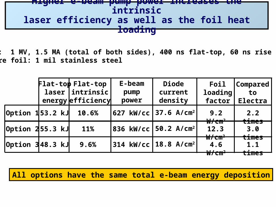
Higher e-beam pump power increases the intrinsiclaser efficiency as well as the foil heat loading
Diodes: 1 MV, 1.5 MA (total of both sides), 400 ns flat-top, 60 ns rise and fallPressure foil: 1 mil stainless steel
Diodecurrentdensity
Flat-toplaser
energy
Flat-topintrinsic
efficiency
E-beampumppower
Foilloadingfactor
Comparedto
Electra
Option 1 37.6 A/cm253.2 kJ 10.6% 627 kW/cc 9.2 W/cm2 2.2 times
Option 3 48.3 kJ 9.6% 314 kW/cc 4.6 W/cm2 1.1 times18.8 A/cm2
Option 2 55.3 kJ 11% 836 kW/cc 12.3 W/cm2 3.0 times50.2 A/cm2
All options have the same total e-beam energy deposition
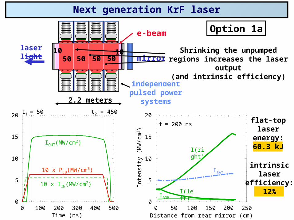
Next generation KrF laser
Option 1ae-beam
50 50 50 50 mirror
2.2 meters
10 10
independentpulsed power
systems
laser light
IOUT(MW/cm2)
10 x IIN(MW/cm2)
10 x PEB(MW/cm3)
15
10
5
0
20
Time (ns)2000 400 500100 300
t1 = 50 t2 = 450
Distance from rear mirror (cm)1000 25050 150 200
t = 200 ns
I(right)
I(left)IASE
ISAT
15
10
5
0
20
Inte
nsity
(M
W/c
m2 )
flat-toplaser
energy:60.3 kJ
intrinsiclaser
efficiency:12%
Shrinking the unpumpedregions increases the laser output
(and intrinsic efficiency)
Shrinking the unpumpedregions increases the laser output
(and intrinsic efficiency)
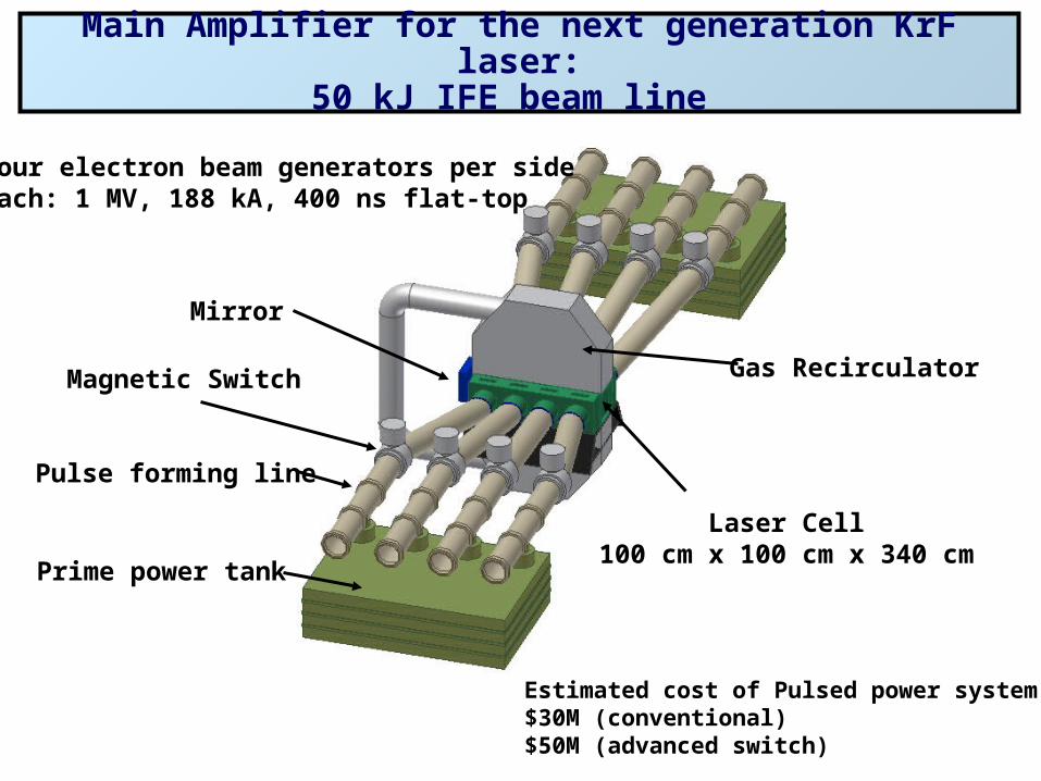
Main Amplifier for the next generation KrF laser:50 kJ IFE beam line
Estimated cost of Pulsed power system:$30M (conventional)$50M (advanced switch)
Prime power tank
Pulse forming line
Magnetic Switch Gas Recirculator
Mirror
Laser Cell100 cm x 100 cm x 340 cm
Four electron beam generators per sideeach: 1 MV, 188 kA, 400 ns flat-top
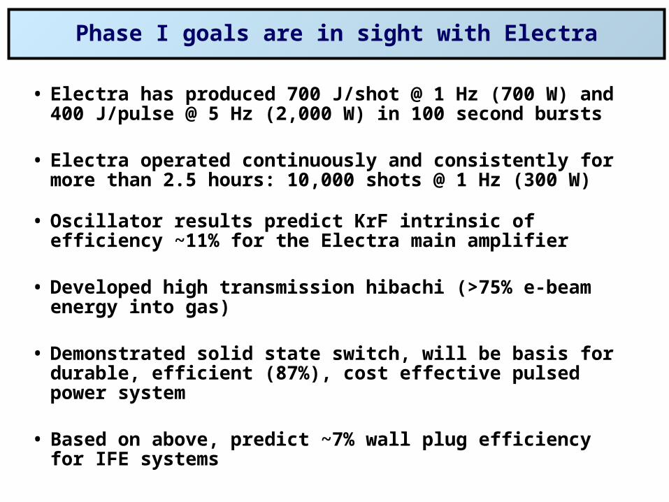
Phase I goals are in sight with Electra
• Electra has produced 700 J/shot @ 1 Hz (700 W) and 400 J/pulse @ 5 Hz (2,000 W) in 100 second bursts
• Electra operated continuously and consistently for more than 2.5 hours: 10,000 shots @ 1 Hz (300 W)
• Oscillator results predict KrF intrinsic of efficiency ~11% for the Electra main amplifier
• Developed high transmission hibachi (>75% e-beam energy into gas)
• Demonstrated solid state switch, will be basis for durable, efficient (87%), cost effective pulsed power system
• Based on above, predict ~7% wall plug efficiency for IFE systems


![Brian.Hicks@nrl.navy.mil arXiv:1210.0506v1 [astro-ph.IM] 1 ... · Naval Research Laboratory, Code 7213, Washington, DC 20375-5320 Brian.Hicks@nrl.navy.mil Nagini Paravastu-Dalal1](https://img.pdfslide.us/doc/110x75/60107f3cc77ab87d6d4fe21c/brianhicksnrlnavymil-arxiv12100506v1-astro-phim-1-naval-research-laboratory.jpg)