Embed Size (px)
Citation preview
NAVAL
POSTGRADUATE SCHOOL
MONTEREY, CALIFORNIA
THESIS
Approved for public release; distribution is unlimited.
AERIAL COMMAND AND CONTROL UTILIZING WIRELESS MESHED NETWORKS IN SUPPORT OF JOINT
TACTICAL COALITION OPERATIONS by
Christopher R. Lee
September 2005
Thesis Advisor: James Ehlert Second Reader: Brian Steckler

THIS PAGE INTENTIONALLY LEFT BLANK
i
REPORT DOCUMENTATION PAGE Form Approved OMB No. 0704-0188
Public reporting burden for this collection of information is estimated to average 1 hour per response, including the time for reviewing instruction, searching existing data sources, gathering and maintaining the data needed, and completing and reviewing the collection of information. Send comments regarding this burden estimate or any other aspect of this collection of information, including suggestions for reducing this burden, to Washington headquarters Services, Directorate for Information Operations and Reports, 1215 Jefferson Davis Highway, Suite 1204, Arlington, VA 22202-4302, and to the Office of Management and Budget, Paperwork Reduction Project (0704-0188) Washington DC 20503.
1. AGENCY USE ONLY (Leave blank)
2. REPORT DATE September 2005
3. REPORT TYPE AND DATES COVERED Master’s Thesis
4. TITLE AND SUBTITLE: Aerial Command and Control Utilizing Wireless Meshed Networks in Support of Joint Tactical Coalition Operations
6. AUTHOR(S) Christopher Ray Lee
5. FUNDING NUMBERS
7. PERFORMING ORGANIZATION NAME(S) AND ADDRESS(ES) Naval Postgraduate School Monterey, CA 93943-5000
8. PERFORMING ORGANIZATION REPORT NUMBER
9. SPONSORING /MONITORING AGENCY NAME(S) AND ADDRESS(ES) N/A
10. SPONSORING/MONITORING AGENCY REPORT NUMBER
11. SUPPLEMENTARY NOTES The views expressed in this thesis are those of the author and do not reflect the official policy or position of the Department of Defense or the U.S. Government.
12a. DISTRIBUTION / AVAILABILITY STATEMENT Approved for public release; distribution unlimited
12b. DISTRIBUTION CODE A
13. ABSTRACT (maximum 200 words) This thesis explores the ability of Wi-Fi technology and the Institute of
Electrical and Electronic Engineers (IEEE) 802.11 capability to disseminate various forms of information through densely vegetated, high humidity and high temperature environments. Using a lighter-than-air vehicle (balloon) and existing commercial-off-the-shelf, 802.11b and 802.16 wireless components, real-time information can be brought to the war-fighter.
In particular, this thesis experiments with the use of commercially available wireless equipment and various antennae all attached to a helium-filled balloon to send and receive video, audio and digital information. This information is then disbursed to individual members of an established network over a specified land-mass. The balloon plays an important role in connecting network members to information that helps local and national commanders in making tactical decisions. These decisions consist of deploying forces, identifying and targeting the enemy, and deterring hostilities. Identifying the best method to supply real-time data to facilitate the movement of military assets and enhance a military’s ability to engage an enemy decisively.
Employing commercial-off-the-shelf (COTS) systems to disseminate real-time information is a potentially inexpensive solution to enable air and ground components to survey and target adversaries instantaneously. The ability to provide actionable information to the soldier serves as a force multiplier and increases the probability of mission success.
15. NUMBER OF PAGES
201
14. SUBJECT TERMS Wi-Fi, Mesh Networks, Surveillance and Targeting, Balloons, 2.4 GHz antennae, signal propagation, Breadcrumb, 802.11b, 802.16, Balloons, Coalition Operating Area Surveillance and Targeting System (COASTS)
16. PRICE CODE
17. SECURITY CLASSIFICATION OF REPORT
Unclassified
18. SECURITY CLASSIFICATION OF THIS PAGE
Unclassified
19. SECURITY CLASSIFICATION OF ABSTRACT
Unclassified
20. LIMITATION OF ABSTRACT
UL
NSN 7540-01-280-5500 Standard Form 298 (Rev. 2-89) Prescribed by ANSI Std. 239-18

ii
THIS PAGE INTENTIONALLY LEFT BLANK
iii
Approved for public release; distribution is unlimited.
AERIAL COMMAND AND CONTROL UTILIZING WIRELESS MESHED NETWORKS IN SUPPORT OF JOINT TACTICAL COALITION OPERATIONS
Christopher R. Lee
Lieutenant, United States Navy M.S., Naval Post Graduate School, 2005
Submitted in partial fulfillment of the requirements for the degree of
MASTER OF SCIENCE IN SYSTEMS ENGINEERING
from the
NAVAL POSTGRADUATE SCHOOL September 2005
Author: Christopher R. Lee Approved by: James Ehlert
Thesis Advisor
Brian Steckler Second Reader
Dan Boger Chairman, Department of Information Sciences

iv
THIS PAGE INTENTIONALLY LEFT BLANK
v
ABSTRACT
This thesis explores the ability of Wi-Fi technology
and the Institute of Electrical and Electronic Engineers
(IEEE) 802.11 capability to disseminate various forms of
information through densely vegetated, high humidity and
high temperature environments. Using a lighter-than-air
vehicle (balloon) and existing commercial-off-the-shelf
(COTS), 802.11b and 802.16 wireless components, real-time
information can be brought to the war-fighter.
In particular, this thesis experiments with the use of
commercially available wireless equipment and various
antennae all attached to a helium-filled balloon to send
and receive video, audio and digital information. This
information is then disbursed to individual members of an
established network over a specified land-mass. The
balloon plays an important role in connecting network
members to information that helps local and national
commanders in making tactical decisions. These decisions
consist of deploying forces, identifying and targeting the
adversary, and deterring hostilities. Identifying the best
method to supply real-time data to facilitate the movement
of military assets and enhance a military’s ability to
engage an enemy decisively.
Employing COTS systems to disseminate real-time
information is a potentially inexpensive solution to enable
air and ground components to survey and target adversaries
instantaneously. The ability to provide actionable
information to the soldier serves as a force multiplier and
increases the probability of mission success.

vi
THIS PAGE INTENTIONALLY LEFT BLANK
vii
TABLE OF CONTENTS
I. INTRODUCTION ......................................... 1 A. WIFI IMPLEMENTATION TO THE TACTICAL USER ........ 1 B. EXTENDING COMMAND AND CONTROL ................... 2 C. COASTS .......................................... 4
1. Background ................................. 4 2. Purpose .................................... 4 3. COASTS Tactical Implementation ............. 5
D. OBJECTIVE OF RESEARCH ........................... 6 II. THE TACTICAL NETWORK ................................. 7
A. COASTS 2005 TOPOLOGY ............................ 7 1. Description of Network Assets .............. 8
a. Wing 2 Air Tower ...................... 8 b. Wing 2 Communications Building ........ 8 c. Balloon Node .......................... 9 d. Lop Buri Downtown Communication
Building ............................. 11 e. Lop Buri Mountain Communication
Facility ............................. 11 B. OVERCOMING THE INFORMATION GAP ................. 12
III. THE BALLOON SYSTEM .................................. 15 A. ENVIRONMENTAL EFFECTS .......................... 15
1. Temperature and Sunlight Effects .......... 15 2. Humidity Effects .......................... 18 3. Wind Speed and Flow Patterns .............. 18 4. Terrain Contour ........................... 19
B. THE BALLOON .................................... 19 C. THE PLATFORM ................................... 21
1. Platform .................................. 21 2. The Winch and Tether ...................... 21
D. LESSONS LEARNED ................................ 22 IV. THE BALLOON PAYLOAD ................................. 25
A. THE BREADCRUMB ................................. 25 B. THE PAYLOAD .................................... 27
1. Weight Considerations ..................... 28 2. Payload Power Supply ...................... 30 3. Payload Cameras ........................... 33
C. LESSONS LEARNED ................................ 36 V. ANTENNAE .......................................... 37
A. PAYLOAD ANTENNAE ............................... 37 1. Omni-directional Antenna .................. 38
viii
2. 5-dBi Omni-Directional Antenna ............ 40 3. Yagi Antenna .............................. 43
B. CAPABILITIES AND LIMITATIONS ................... 45 C. LESSONS LEARNED ................................ 47
VI. CONCLUSION AND RECOMMENDATIONS ...................... 49 A. CONCLUSION ..................................... 49 B. FUTURE PROJECTS ................................ 50 C. RECOMMENDATIONS ................................ 52
APPENDIX A. COASTS 2005 CONCEPT OF OPERATIONS ......... 55 APPENDIX B. TETHERED BALLOON ASSEMBLY ................ 131 APPENDIX C. COASTS 2005 AFTER ACTION REPORT .......... 147 LIST OF REFERENCES ...................................... 179 INITIAL DISTRIBUTION LIST ............................... 183
ix
LIST OF FIGURES Figure 1. COASTS 2005 Network Topology in Lop Buri,
Thailand (From Ref 34) .............................7 Figure 2. Tool Box Payload COASTS March 2005 ................10 Figure 3. COASTS-MayDemo-RealTopo (From Ref 34) .............12 Figure 4. Balloon after Eight Hours of Operation, March
2005 ..............................................17 Figure 5. Balloon after Four Hours of Operation, May 2005 ...17 Figure 6. Sky-Doc Balloon in Flight at 100 Feet .............20 Figure 7. Balloon Platform with Winch and Helium Bottles ....22 Figure 8. Virtual Display of Breadcrumb Network .............26 Figure 9. Breadcrumb Packages (Breadcrumb XL, SE, ME) and
Battery ...........................................27 Figure 10. Tool Box Payload with 2W Amplifier and Camera
Mount .............................................28 Figure 11. Thunder Power (left) and UB 2590 Batteries.......30 Figure 12. May 2005 Balloon Payload.........................32 Figure 13. May 2005 Payload with Supercrumb and Fan.........32 Figure 14. Video Stream from the Balloon Payload, March
2005 ..............................................33 Figure 15. 4XEM Camera (left) and Sony Camera...............35 Figure 16. Yagi (left), Omni-Directional and Multi-Polar
Antennae ..........................................38 Figure 17. 8 dBi Antenna Beamwidths (From Ref 35)...........39 Figure 18. 5-dBi Multi-Polar Antenna Beamwidths (From Ref
36) ...............................................42 Figure 19. 14.5-dBi Yagi Antenna Beamwidths (From Ref 35)...45

x
THIS PAGE INTENTIONALLY LEFT BLANK

xi
LIST OF TABLES Table 1. 8-dBi Omni-Directional Hyperlink Antenna
Characetristics (From Ref 35) .....................39 Table 2. 5-dBi Multi-Polar WiFi-Plus Antenna
Characetristics (From Ref 36) .....................41 Table 3. 14.5-dBi Semi-directional Yagi Characteristics
(From Ref 35) .....................................44

xii
THIS PAGE INTENTIONALLY LEFT BLANK
xiii
ACKNOWLEDGMENTS
I would like to thank my wife for her consistent
patience and loving support throughout this whole endeavor.
The time away from home was very stressful and she handled
everything with superior strength and grace. Thank you for
your love and understanding Bernadette.
I want to recognize a few people that were influential
in creating the opportunity to conduct the research and
helping me obtain the equipment used throughout this
experiment. Jim Ehlert has been my mentor and friend
during the entire process. Jim’s faith in my abilities to
contribute to the COASTS 2005 experiment was the driving
force of this thesis. A ‘Thank You’ is also sent to Dr.
Kevin Jones. His availability and technical assistance in
designing the balloon payload was priceless.
Without the help of the entire COASTS 2005 staff,
specifically Scott Cone, Steve Urrea, David Cooper, Mike
Clement and Bruce Iverson, this experiment would not have
taken place. A special thanks goes out to the COASTS 2005
Triad.

xiv
THIS PAGE INTENTIONALLY LEFT BLANK
xv
LIST OF ACRONYMS and ABBREVIATIONS
AUV Autonomous (Unmanned) Underwater Vehicle BKK Bangkok
BCA Breadcrumb Administration
C2 Command and Control
COC Command Operations Center COASTS Coalition Operating Area Surveillance and Targeting System
COTS Commercial off the Shelf
DC Direct Current DRDO Department of Research and Development Office FCC Federal Communications Commission
FLTSATCOM Fleet Satellite Communication GHz Giga Hertz GPS Global Positioning System IEEE Institute of Electrical and Electronic Engineers ISR Intelligence, Surveillance, and Reconnaissance Mission (ISR) JIATF-WEST Joint Inter Agency Task Force- West JUSMAGTHAI Joint US Military Advisors Group Thailand KIAS Knot Indicated Air Speed Li-Ion Lithium Ion Mbps Mega-bits per second
MCP Mobile Command Post MILSTAR Military Satellite MOE Measures of Effectiveness MOP Measures of Performance NPS Naval Postgraduate School OTH Over The Horizon PDA Personal Data Assistant
xvi
PZT Pan-Zoom-Tilt RF Radio Frequency ROE Rules of Engagement RTA Royal Thai Army RTAF Royal Thai Air Force RTARF Royal Thai Armed Forces RTSC Royal Thai Supreme Command PDA Personal Digital Assistant SATCOM Satellite Communications SCR Single Channel Radio SSA Shared Situational Awareness STAN Surveillance and Targeting Network TNT FE Tactical Network Topology Field Experiment TOC Tactical Operations Center UAV Unmanned Aerial Vehicle USPACOM U.S. Pacific Command USSOCOM U.S. Special Operations Command WI-FI Wireless Fidelity WLAN Wireless Local Area Network WOT War on Terror VLAN Virtual Land Area Network VDC Voltage-Direct Current
THIS PAGE INTENTIONALLY LEFT BLANK
1
I. INTRODUCTION
A. WIFI IMPLEMENTATION TO THE TACTICAL USER
The development of Wireless LAN (Local Area Networks)
technology (WLAN), also known as Wi-Fi or Wireless Fidelity,
has significantly changed the communications industry.
People can access the Internet via cellular phones, personal
digital assistants (PDAs) and pagers. Wi-Fi technology has
become a convenient and reliable method of providing
instant, highly flexible, and mobile network access. WLANs
extend the connectivity of a network via the Institute of
Electrical and Electronic Engineers (IEEE) 802.11-based
products.
The concepts and application of wireless technology has
been thoroughly investigated; however, research that
integrates independent wireless systems to operate as a
seamlessly distributed network in a highly hostile
environment is limited. A technologically advanced military
should consider the following two objectives: 1) employing
802.11 assets to facilitate the rapid deployment of military
forces, and 2) creating a communication platform that
provides multiple capabilities in one package. Processing
applicable information over an 802.11-based pipeline
minimizes the cost and time to deploy forces.
Currently, numerous applications are being used to
communicate with forward-deployed units. For example,
single-channel radios (SCRs) are the principal means for
communication among air-ground units. Most units must
combine these systems with hardware/software components from
satellite systems, such as FLTSATCOM, MILSTAR and MILSATCOM,
2
in order to transmit appropriate tactical information to the
strategic and operational commander. Furthermore, the
advance in 802.11 technologies has created the opportunity
to eliminate excess gear. WLANS can be deployed with
tactical units to replace current communication devices.
This minimizes the footprint and reduces the time needed to
create a real-time tactical picture for the on-scene
military commander.
The individual combatant needs to communicate with his
chain-of-command, and perhaps even the military commander,
to send and receive essential military information
applicable to the battlefield. Wi-Fi can be used to fulfill
this requirement. Integrated wireless components can be
equipped to military assets that include:
• Unmanned Aerial Vehicles (UAVs)
• Lighter-than-air Vehicles (balloons)
• Individual Soldiers
• Ground Vehicles.
Combining these capabilities offers an inexpensive
solution to mitigate communication gaps between the war-
fighter and the combatant commander.
B. EXTENDING COMMAND AND CONTROL
Tactical units often struggle to maintain connectivity
with their network. A stationary, lighter-than-air vehicle
is an ideal feature to incorporate onto the battlefield to
help address this limitation. A helium-filled, tethered
balloon offers the advantage of an increased line of sight
(LOS), over the horizon (OTH), Wi-Fi relay platform. The
3
balloon can be outfitted with various antennae and
amplifiers enabling the free-flow of viable information to
and from the military commander. A strategic commander can
maintain a safe distance from a hostile situation and can
continue to support active forces miles away.
Helium balloons offer an inexpensive solution to
maintaining the visual, audio, and sensory information
required to conduct tactical operations. They can be
deployed within minutes and maneuvered into a position 2000
to 3,000 feet in the air, with a minimum radar cross section
(RCS) and at an altitude safe from light-arms fire. Equipped
with an antenna, and the appropriate RF hardware, a war-
fighter can access the local tactical network through the
balloon and receive real-time information while engaging a
threat. The variety of information transferred is limited
to the 802.11 bandwidth and the software capabilities of the
individual units.
Military forces must frequently enter environments that
can limit or undermine the capabilities of current
communication tools. A lighter-than-air command and control
platform can be deployed in any type of environment and any
type of weather. By combining an all-weather balloon,
equipped with Wi-Fi technology, and multiple ground Wi-Fi
units, instant situational awareness and tactical
communication can be achieved over any land or water mass.
This adaptability and scalability enhances communication
response times and tactical decision-making, thereby helping
create an advantage over potential adversaries.
4
C. COASTS
1. Background
The Coalition Operating Area Surveillance and Targeting
System (COASTS) is a Naval Postgraduate School (NPS) field
experiment that is modeled after a similar successful
program, previously known as Surveillance and Targeting
Network (STAN). STAN is now called the Tactical Network
Topology Field Experiment (TNT-FE). The TNT-FE program was
initiated to support a U.S. Special Operations Command
(USSOCOM) requirement in researching the integration of
emerging WLAN technologies with surveillance and targeting
hardware/software systems supporting USSOCOM missions.
(COASTS 2005 Concept of Operations, p. 1)
Due to the classification levels of the TNT FE program,
certain Department of Defense requirements to facilitate
operations in coalition environments remained unfulfilled.
The COASTS program intends to provide the fully shareable
and reliable Wi-Fi integration capabilities to present and
future coalition forces without compromising classified and
operationally sensitive tactics, techniques, or procedures.
(COASTS 2005 Concept of Operations, p. 1)
2. Purpose
COASTS is an ongoing field experiment that includes the
technological expertise of NPS’s students and faculty.
Experiments involve using current WLAN technologies which
provide the backbone to integrate and to display information
from air and ground sensors to a real-time, tactical,
coalition command and control center. COASTS supports the
U.S. Pacific Command (USPACOM), Joint U.S. Military
Advisor’s Group Thailand (JUSMAGTHAI), Naval Postgraduate
School, Thailand Royal Thai Supreme Command (RTSC), Royal
5
Thai Armed Forces (RTARF), and the Thai Defense Research and
Development Office (DRDO) research requirements relating to
theater security, host nation security, and the War on
Terror (WOT). (COASTS 2005 Concept of Operations, p. 1)
3. COASTS Tactical Implementation
Many current tactical systems are unable to integrate a
common operating picture among air, surface and sub-surface
forces through an autonomous network. COASTS is a small unit
network that provides communication capabilities using an
open, plug-and-play architecture, all of which is user
configurable. The network consists of balloons, UAVs, and
portable and fixed ground sensors communicating by wireless
network technology. The network is connected via the
following hardware/software suites:
• 802.11b
• 802.16 Orthogonal Frequency Division Multiplexing
(OFDM)
• Satellite Communications (SATCOM)
• Situational Awareness Software
• Wearable Computing Devices
• Air and Ground Sensors
• Mobile/Fixed Command and Control Platforms.
Using a minimum of resources, this network, once
established in and around hostile environments, provides a
real-time, threat warning and surveillance capability.
Mobile components of the network can move freely within the
network while maintaining visual and digital communications
with all other users, nodes, and components. This

6
translates into a force multiplier by furnishing real-time
surveillance and targeting data to those units who require
it. The tactical network efficiently directs combat units
towards a potential or existing threat.
D. OBJECTIVE OF RESEARCH
A rapidly deployed, all weather, tactical, 802.11 based
network can be achieved by using small portable transceivers
that can instantly establish a wireless meshed digital
network. The creation, integration, and testing of a rapidly
deployable, lighter-than-air, wireless command and control
platform is the primary focus of this research.
This thesis investigates the capability of commercial
portable transceivers and their operational characteristics,
in a highly humid, densely vegetated, extremely hot
environment with the emphasis on establishing a lighter-
than-air wireless relay. Using a helium-filled balloon and
current COTS systems, an 802.11b network can supply the
necessary visual and sensory information to extend the
surveillance and targeting capabilities of a small, forward
deployed tactical unit.
7
II. THE TACTICAL NETWORK
A. COASTS 2005 TOPOLOGY
The COASTS 2005 experiment employed and integrated
numerous COTS systems to establish a network for authorized
individuals to access. Each component of the network, or
node, seamlessly provided a communication link to every
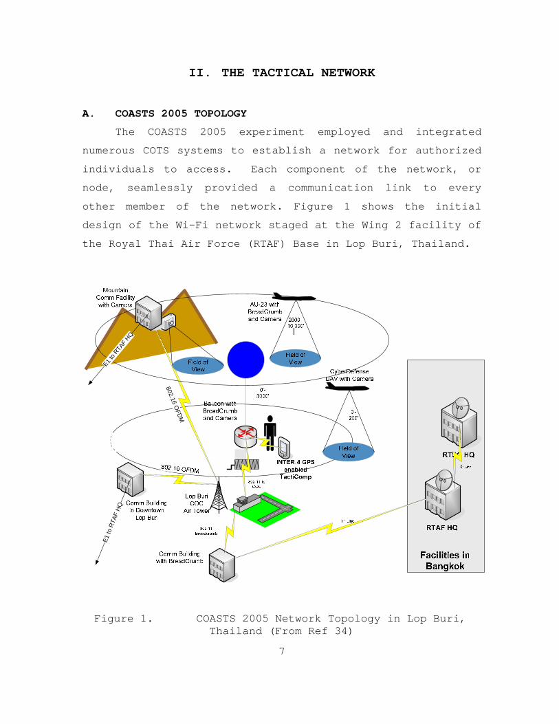
other member of the network. Figure 1 shows the initial
design of the Wi-Fi network staged at the Wing 2 facility of
the Royal Thai Air Force (RTAF) Base in Lop Buri, Thailand.
802.16 OFD
M
E1 to
RTA
F H
Q
E1 to R
TAF
HQ
Figure 1. COASTS 2005 Network Topology in Lop Buri, Thailand (From Ref 34)
8
1. Description of Network Assets
The network had five major nodes consisting of the following:
• Wing 2 Air Tower
• Wing 2 Communications Building
• Balloon Node
• Lop Buri Downtown Communications Building
• Lop Buri Mountain Communications Facility.
Each node was equipped with the appropriate wireless
components with respect to the node’s distance from the
network and the type of information the node disseminated
through the network.
a. Wing 2 Air Tower
The Command and Control (C2) function of the
network was located in the Command Operations Center (COC),
which for this experiment, was assembled in the Wing 2 Air
Tower. The COC was equipped with a switch configured to
create Virtual Land Area Networks (VLANs) to process and to
distribute 802.11b and 802.16 signals in the network. Other
components located in the COC included a Shared Situational
Awareness application (called TrakPoint) Server, a 802.11
router, and various laptops. Personnel in the COC were
tasked with monitoring video streams, Rajant Breadcrumb
connectivity strength, and network throughput while
functioning as the tactical C2 element for the experiment.
b. Wing 2 Communications Building
The Wing 2 Communications Building housed the land
connection to send network information to the strategic
elements of the network. This land connection was a T1 line
9
that connected the Wing 2 Communications Building to the
RTAF HQ located in Bangkok. This site is connected to the
network through a Rajant Breadcrumb that receives 802.11b
data and transfers same to the T1 line through a router.
c. Balloon Node
The balloon node bridges the 802.11b capable
components to the Wing 2 Air Tower again using a Rajant
Breadcrumb. Deployed forces, requiring instant situational
awareness (SA) of the local environment, must maintain
access to the tactical network. An airborne, wireless
access point is fixed to a helium balloon, which provides
the necessary capability for ground and air units to
communicate with the COC. The balloon carries a payload
with the following components:
• Internet Protocol (IP) Enabled Camera
• 802.11b Wireless Transceiver (Rajant Breadcrumb)
• 2.4 to 2.5 GHz Antenna.
10
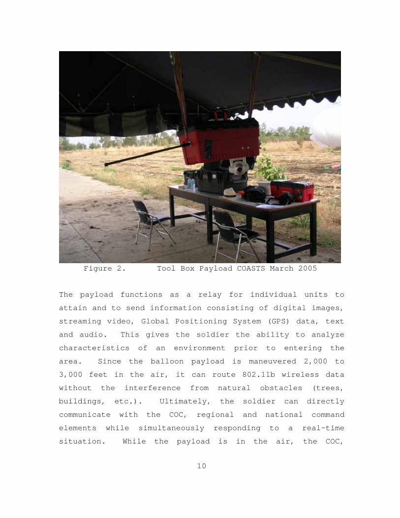
Figure 2. Tool Box Payload COASTS March 2005
The payload functions as a relay for individual units to
attain and to send information consisting of digital images,
streaming video, Global Positioning System (GPS) data, text
and audio. This gives the soldier the ability to analyze
characteristics of an environment prior to entering the
area. Since the balloon payload is maneuvered 2,000 to
3,000 feet in the air, it can route 802.11b wireless data
without the interference from natural obstacles (trees,
buildings, etc.). Ultimately, the soldier can directly
communicate with the COC, regional and national command
elements while simultaneously responding to a real-time
situation. While the payload is in the air, the COC,
11
deployed units and remote elements, can obtain the same
real-time information simultaneously.
d. Lop Buri Downtown Communication Building
The Lop Buri Downtown Communication Building
received data from the 802.16 link from the Air Tower and
sent these data to the RTAF HQ via an existing E1 line
through a staged router. The Downtown facility was located
approximately 10 kilometers from the Wing 2 Communications
Building.
e. Lop Buri Mountain Communication Facility
The Mountain Facility was used to test the ability
of Redline Communication’s 802.16 equipment and to act as a
forward deployed unit in the network. The data collected at
the Air Tower could have been accessed by the Mountain
Facility, but this node was not outfitted with equipment to
monitor the network. Images from the Mountain Facility
camera were sent to the Air Tower via the 802.16 link.
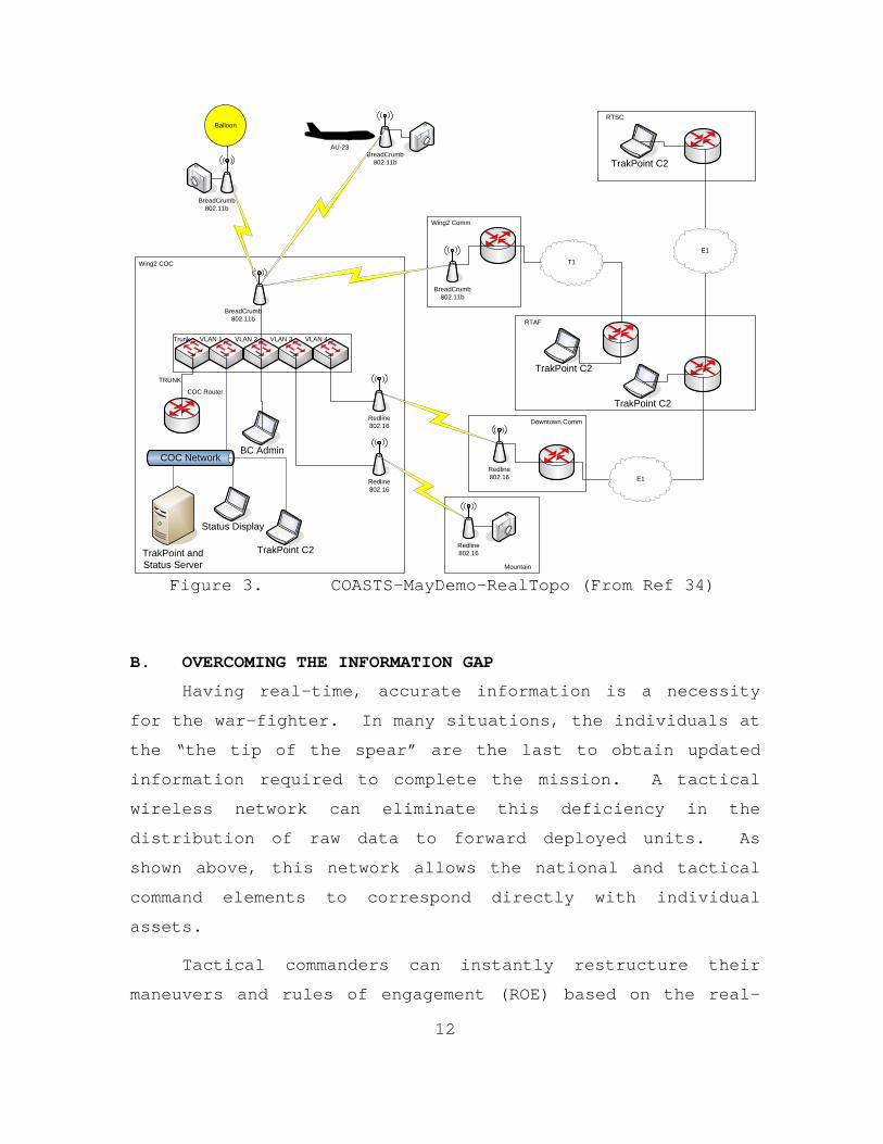
A diagram depicting data transfer during the
experiment is presented in Figure 2 below. The Royal Thai
Supreme Command received all network traffic with an E1 line
connected to the RTAF HQ. This particular link enabled
situational awareness on the national level.
12
Trunk VLAN 2VLAN 1 VLAN 3 VLAN 4
COC Router
TRUNK
COC NetworkBC Admin
Status Display
TrakPoint C2
BreadCrumb802.11b
Redline802.16
Redline802.16
TrakPoint andStatus Server
BreadCrumb802.11b
Redline802.16
Redline802.16
BreadCrumb802.11b
Balloon
T1
E1
E1
AU-23BreadCrumb
802.11b
TrakPoint C2
TrakPoint C2
RTSC
RTAF
Wing2 COC
Mountain
Wing2 Comm
Downtown Comm
TrakPoint C2
Figure 3. COASTS-MayDemo-RealTopo (From Ref 34)
B. OVERCOMING THE INFORMATION GAP
Having real-time, accurate information is a necessity
for the war-fighter. In many situations, the individuals at
the “the tip of the spear” are the last to obtain updated
information required to complete the mission. A tactical
wireless network can eliminate this deficiency in the
distribution of raw data to forward deployed units. As
shown above, this network allows the national and tactical
command elements to correspond directly with individual
assets.
Tactical commanders can instantly restructure their
maneuvers and rules of engagement (ROE) based on the real-
13
time information processed through the network. Units can
be deployed to the most effective location or vantage point,
helping to mitigate adversary activities. This ability to
focus military assets rapidly assessing the adversary’s
strength, composition, location, and intent is key to a
successful engagement. In his book, On War, Karl von
Clausewitz emphasizes the need to engage the enemy with
speed, diligence, and extreme force to succeed on the
battlefield, as expressed in the following quotation:
The first and most important rule to observe...is to use our entire forces with the utmost energy. The second rule is to concentrate our power as much as possible against that section where the chief blows are to be delivered and to incur disadvantages elsewhere so that our chances of success may increase at the decisive point. The third rule is never to waste time. Unless important advantages are to be gained from hesitation, it is necessary to set to work at once. By this speed a hundred enemy measures are nipped in the bud, and public opinion is won most rapidly. Finally, the fourth rule is to follow up our successes with the utmost energy. Only pursuit of the beaten enemy gives the fruits of victory.
Karl Von Clausewitz

14
THIS PAGE INTENTIONALLY LEFT BLANK
15
III. THE BALLOON SYSTEM
A. ENVIRONMENTAL EFFECTS
When one designs a tethered balloon system for
operation in an all-weather climate, many environmental
conditions must be addressed. Conditions, such as sunlight,
temperature, wind speed, humidity, flow patterns and terrain
contour significantly affect balloon performance. Any one
of these conditions, acting in singular or in plural, can
alter a balloon’s flight characteristics. For the COASTS
2005 experiment, the balloon system required moderate
stability, the ability to lift 16 to 17 pounds of payload
equipment, a deploy time of 30 minutes, and the endurance to
remain on station for four to six hours.
1. Temperature and Sunlight Effects
High temperatures can adversely affect balloon
material. Many balloons are manufactured from synthetic
materials like rubber, polyurethane, latex and Mylar.
Higher temperatures deteriorate these materials which
ultimately reduce the balloon’s ability to remain inflated
for a standard length of time. Combining exposure to direct
sunlight with high temperatures decreases balloon
performance even more.
The most important goal of the network, supplying real-
time information to the soldier, is limited to the time the
balloon is on station. Ideally, the balloon node is deployed
and remains on station as long as tactical units are active.
As mentioned above, exposure to high temperatures and direct
sunlight lessens total operational time of the balloon node.
16
This negatively impacts the flow of real-time information
available to individual tactical units to effectively combat
potential adversaries.
The effect of this combined exposure was seen during
the March and May 2005 experiments. Lop Buri was very hot
and humid with intense sunlight and temperatures exceeding
100ºF. During the initial flight operations in March 2005,
the balloon held air for a period of eight to ten hours
without a requirement to refill. After four days of
operation, the balloon material became discolored and
operation times between refills were reduced to four to six
hours. After the March experiment the balloon was
completely inspected with no visible signs of puncture or
nozzle malfunction.
The flight times remained constant during the first two
days of the May experiment. However, at the end of the
second day, the operational time fell to three hours. Upon
inspection, many small holes were found. These holes were
unforeseen and the only explanation the author could
envision was that the balloon material slowly deteriorated
with exposure and continuous operation (deflating/inflating
operations).
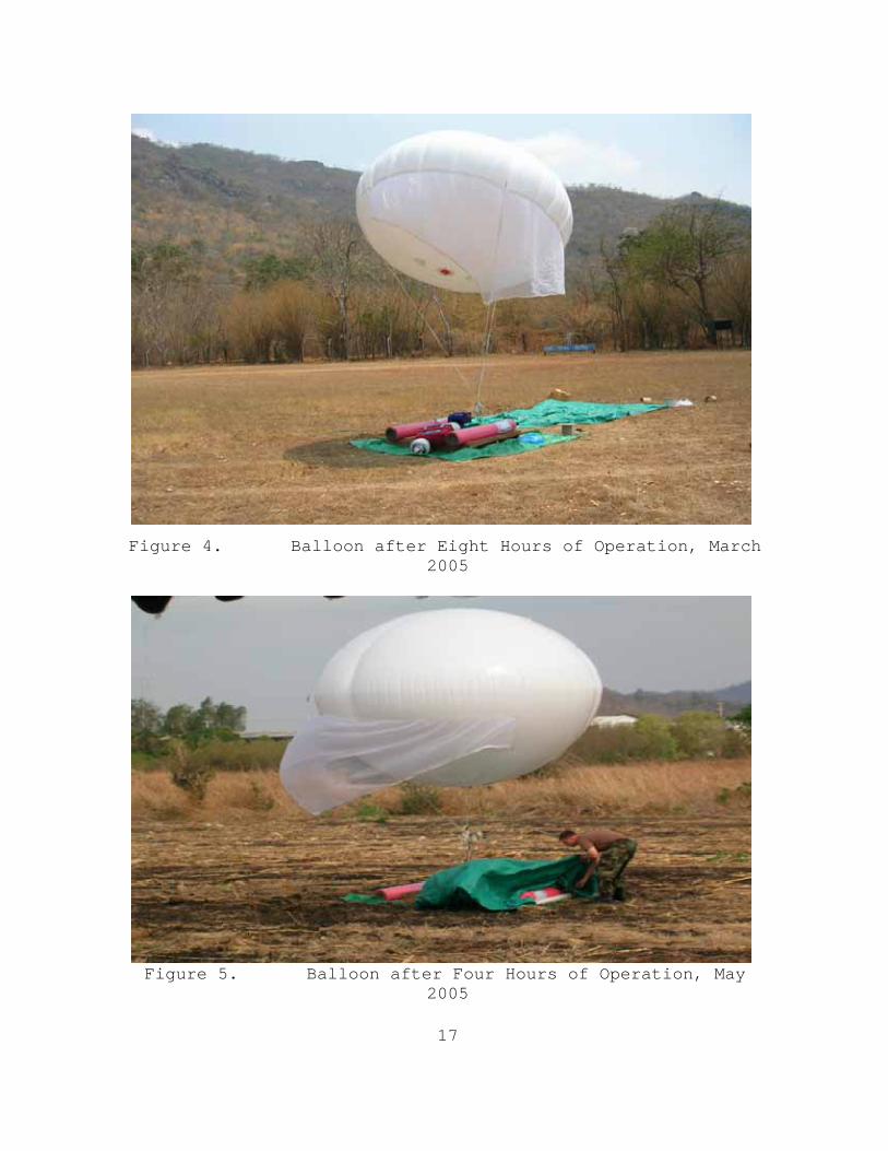
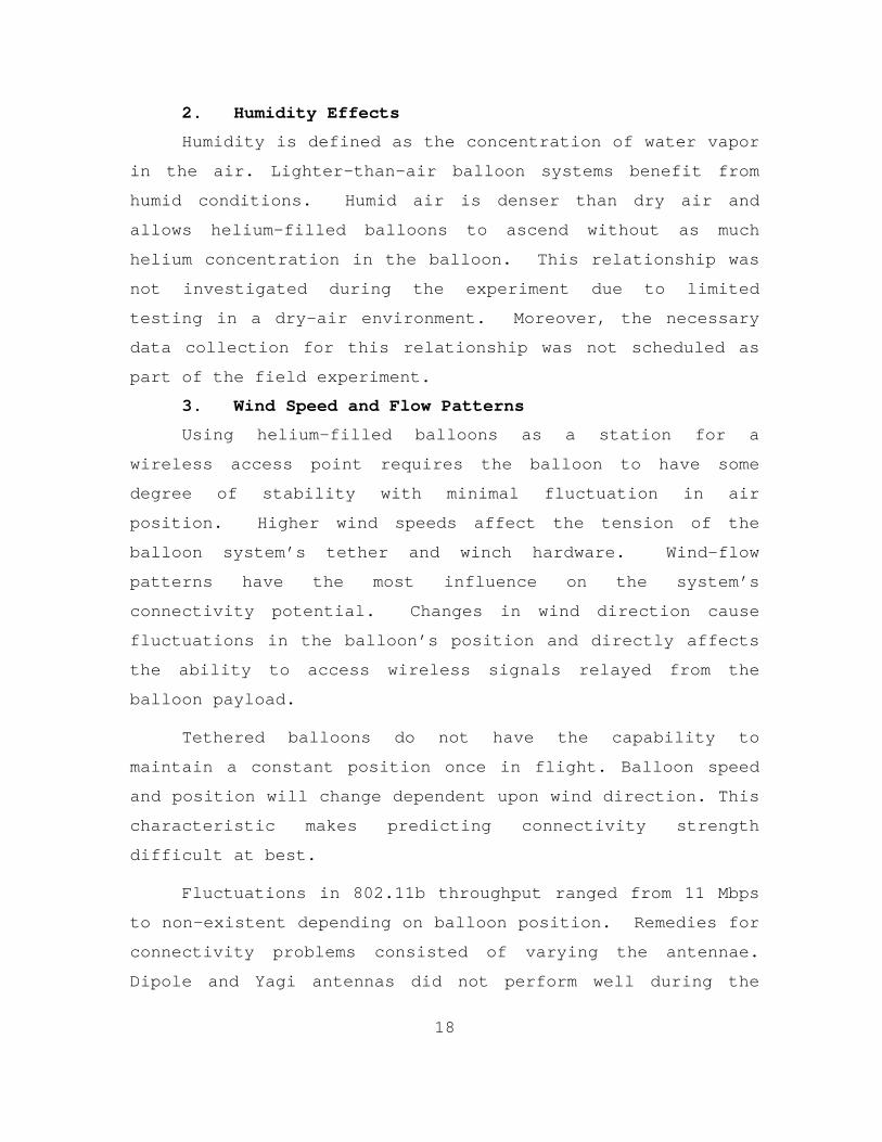
Figures 4 and 5 show the balloon after eight to ten
hours of operation in the March experiment and then after
four to six hours of operation in the May experiment. The
pictures show subtle differences in balloon pressure,
depicted by the creases in the balloon. These photos were
taken prior to refilling the balloon to required levels for
optimal performance.
17
Figure 4. Balloon after Eight Hours of Operation, March 2005
Figure 5. Balloon after Four Hours of Operation, May
2005
18
2. Humidity Effects
Humidity is defined as the concentration of water vapor
in the air. Lighter-than-air balloon systems benefit from
humid conditions. Humid air is denser than dry air and
allows helium-filled balloons to ascend without as much
helium concentration in the balloon. This relationship was
not investigated during the experiment due to limited
testing in a dry-air environment. Moreover, the necessary
data collection for this relationship was not scheduled as
part of the field experiment.
3. Wind Speed and Flow Patterns
Using helium-filled balloons as a station for a
wireless access point requires the balloon to have some
degree of stability with minimal fluctuation in air
position. Higher wind speeds affect the tension of the
balloon system’s tether and winch hardware. Wind-flow
patterns have the most influence on the system’s
connectivity potential. Changes in wind direction cause
fluctuations in the balloon’s position and directly affects
the ability to access wireless signals relayed from the
balloon payload.
Tethered balloons do not have the capability to
maintain a constant position once in flight. Balloon speed
and position will change dependent upon wind direction. This
characteristic makes predicting connectivity strength
difficult at best.
Fluctuations in 802.11b throughput ranged from 11 Mbps
to non-existent depending on balloon position. Remedies for
connectivity problems consisted of varying the antennae.
Dipole and Yagi antennas did not perform well during the
19
experiment. Detailed antenna usage and placement are
discussed in Chapter V of this document.
4. Terrain Contour
The outlay of the land that surrounds the balloon
launch platform determines the optimal altitude the balloon
needs to be positioned at. Mountains and rolling hills
disrupt normal wind patterns. Wind patterns tend to be
circular in regions that have mountainous terrain. Circular
winds negatively affect balloon stability.
In fact, circular winds were very detrimental in the
March 2005 experiment. The initial balloon sight was in the
middle of a valley between two mountains that were 2,000
feet high. The winds came in from the west and deflected
off the mountains, creating a counter-clockwise wind motion.
When the balloon was launched and reached a height of 1,000
feet, these swirling winds caused the balloon to spin out of
control. This reaction made the balloon unstable and flight
operations were suspended until another site was chosen.
B. THE BALLOON
The balloon used in support of COASTS 2005 was
manufactured by Floatograph Inc., and is referred to as the
Sky-Doc Balloon. Sky-Doc Balloons were fabricated to have
the ability to operate in any type of environment and wind
condition. The most significant design feature of these
balloons is their capability to remain stable in extremely
dynamic wind conditions and to maintain a relatively low
depletion rate of helium. These two characteristics,
seemingly, made the Sky-Doc an ideal platform balloon for
operations in Thailand.
20
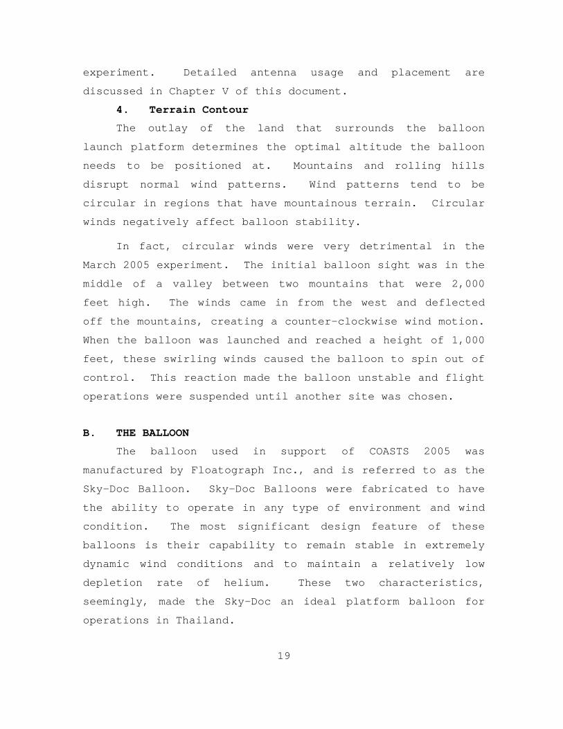
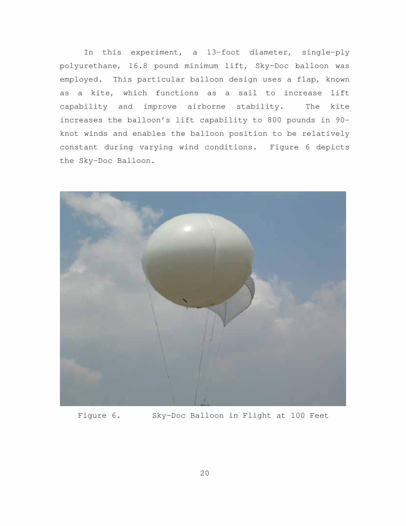
In this experiment, a 13-foot diameter, single-ply
polyurethane, 16.8 pound minimum lift, Sky-Doc balloon was
employed. This particular balloon design uses a flap, known
as a kite, which functions as a sail to increase lift
capability and improve airborne stability. The kite
increases the balloon’s lift capability to 800 pounds in 90-
knot winds and enables the balloon position to be relatively
constant during varying wind conditions. Figure 6 depicts
the Sky-Doc Balloon.
Figure 6. Sky-Doc Balloon in Flight at 100 Feet

21
C. THE PLATFORM
With a potential balloon lift of 800 pounds, the
balloon platform had to be engineered to remain grounded
during flight operations.
1. Platform
The platform is relatively basic in design. Design
requirements articulated light weight, the ability to
withstand the weight of a winch, and to be large enough to
stage helium bottles. The weight of the bottles and winch
acted as the counterforce to the potential lift of the
balloon. The combined weight of the winch and the balloon
was 300 pounds.
It should be mentioned that the use of a platform is
not necessary for balloon operations. The platform provides
a mechanism to tie a safety line to the balloon when flight
operations are complete and presents an excellent area to
stage the winch and helium bottles. The platform design and
necessary parts can be found in Appendix A.
2. The Winch and Tether
When using a balloon with high lift potential, the
winch and tether must be chosen carefully. The winch should
have the braking power to hold the balloon in place. The
COASTS system used a winch manufactured by MT-TE Products
Inc. and which was sold by Floatograph. The winch is rated
for 1,500 pounds of force and weighs 80 pounds. The power
supply is a standard 12 VDC car battery.
The tether is rated for 1,000 pounds of force. The
tether is a standard quarter-inch Spectra line with enough
strength to withstand the potential force that can be
created from the lift of the balloon in hurricane force
22
winds. Winch and tether requirements depend on the type of
balloon used and wind conditions in the area of operations.
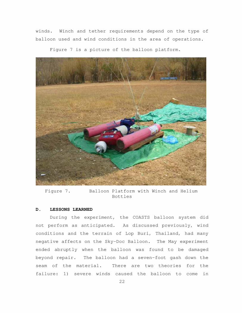
Figure 7 is a picture of the balloon platform.
Figure 7. Balloon Platform with Winch and Helium Bottles
D. LESSONS LEARNED
During the experiment, the COASTS balloon system did
not perform as anticipated. As discussed previously, wind
conditions and the terrain of Lop Buri, Thailand, had many
negative affects on the Sky-Doc Balloon. The May experiment
ended abruptly when the balloon was found to be damaged
beyond repair. The balloon had a seven-foot gash down the
seam of the material. There are two theories for the
failure: 1) severe winds caused the balloon to come in

23
contact with the surrounding trees and bushes, puncturing
the balloon; 2) the puncture and tear were caused by
vandals.
Some evidence supported vandalism, but the extreme
winds in Lop Buri had created similar conditions for
material failure. A detailed list of lessons learned for
balloon operations and equipment usage can be found in
Appendix C.

24
THIS PAGE INTENTIONALLY LEFT BLANK
25
IV. THE BALLOON PAYLOAD
A. THE BREADCRUMB
Obtaining the necessary information to complete a
mission’s objectives relies on the processing efficiency of
the equipment the soldiers use. Tactical networks must
provide an easily accessible environment capable of
communicating with a variety of components to ensure that
tactical, regional and national elements have available
information. The available network must have seamless
throughput to all users during tactical movements, using a
radio frequency spectrum that can deliver video stream,
digital voice, and audio and text simultaneously. To create
such a network, the COASTS 2005 experiment used an 802.11b-
based product known as the Breadcrumb (manufactured by
Rajant Technologies) which functioned as the network
backbone.
The Rajant Breadcrumb is a portable, 802.11b IEEE
standards-based, non-line-of-sight, wireless, self-
configuring broadband network system. A Breadcrumb can be
configured as a DHCP server. Each unit provides Internet
Protocol (IP) addresses to DHCP clients. The tactical
network is initially created by laying out Breadcrumbs at
planned distances from the network origination point. These
devices are programmed to provide its clients with addresses
in the 10.x.y.z space. With all units operating in the same
address space, the soldier can move freely within the mesh
and can maintain communication with all users in the
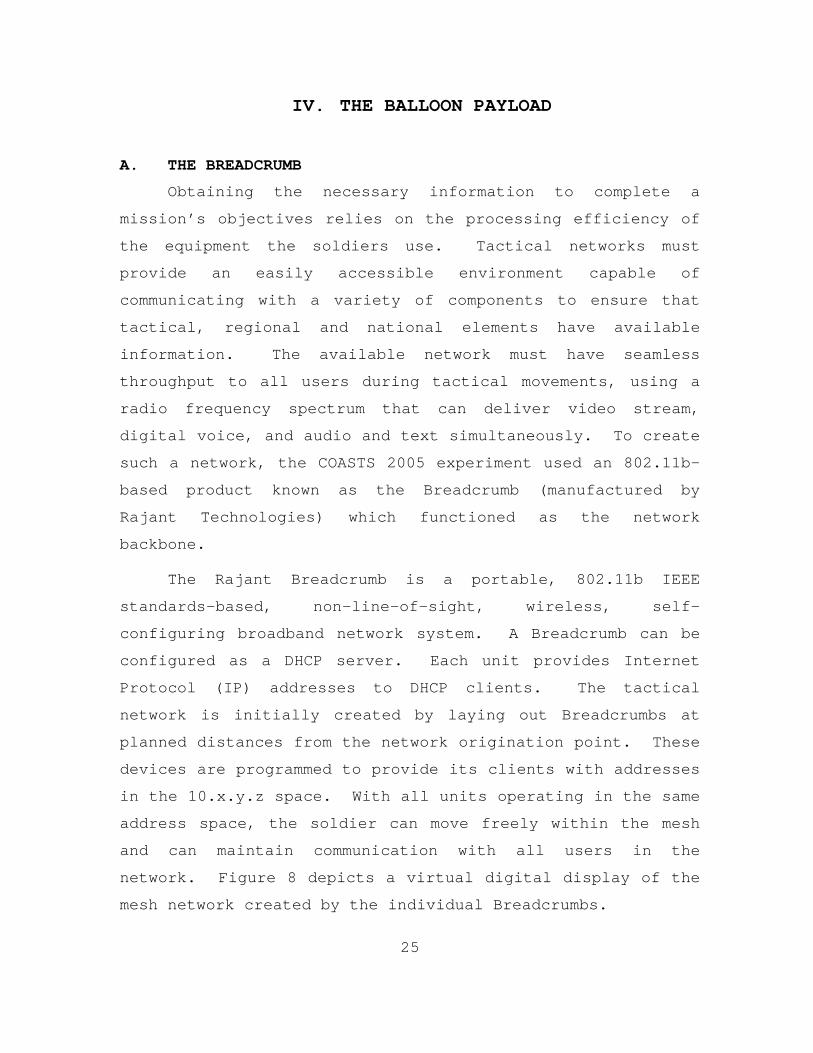
network. Figure 8 depicts a virtual digital display of the
mesh network created by the individual Breadcrumbs.
26
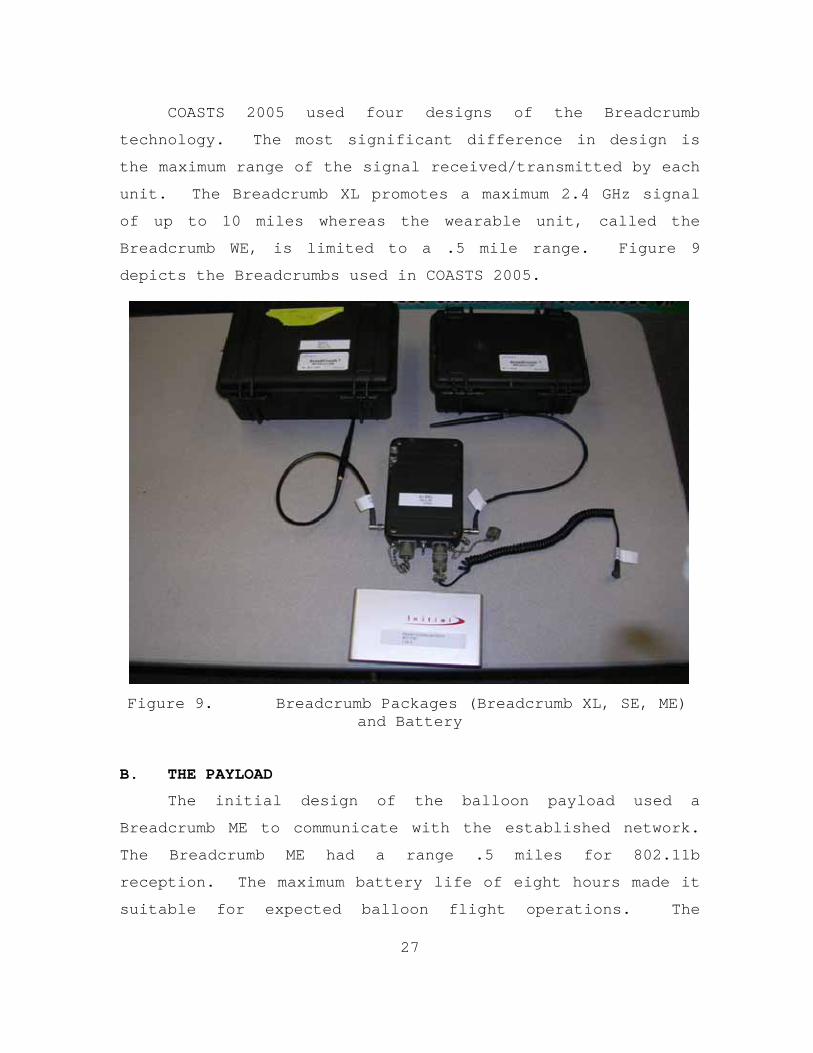
Figure 8. Virtual Display of Breadcrumb Network This display is generated by an administrative software
package known as Breadcrumb Administration (BCAdmin). This
software package comes with all Breadcrumb units and allows
network managers to name individual Breadcrumbs, identify
network clients, and monitor Breadcrumb characteristics,
such as signal strength, MAC addressing, throughput and
channel designation. The larger boxes represent individual
Breadcrumbs, and the smaller boxes depict clients in the
network. Every component of the network is color-coded for
easy recognition and solid/dotted lines represent associated
throughput and signal strength of connected units.
27
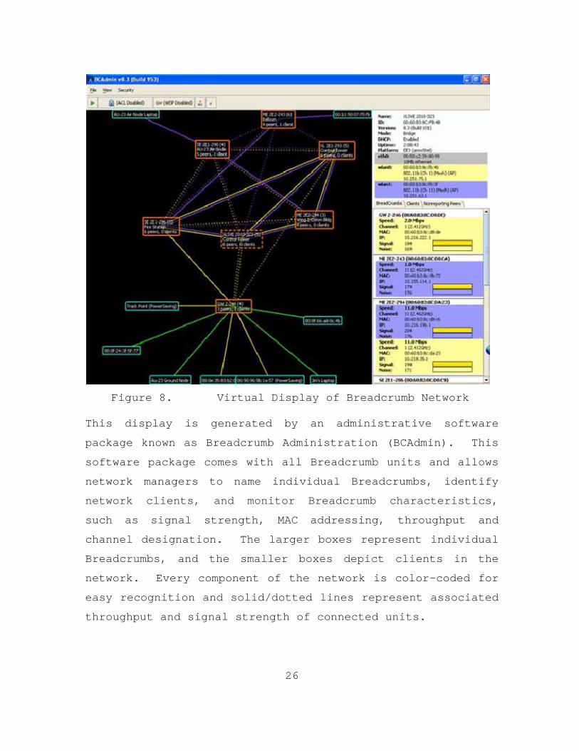
COASTS 2005 used four designs of the Breadcrumb
technology. The most significant difference in design is
the maximum range of the signal received/transmitted by each
unit. The Breadcrumb XL promotes a maximum 2.4 GHz signal
of up to 10 miles whereas the wearable unit, called the
Breadcrumb WE, is limited to a .5 mile range. Figure 9
depicts the Breadcrumbs used in COASTS 2005.
Figure 9. Breadcrumb Packages (Breadcrumb XL, SE, ME) and Battery
B. THE PAYLOAD
The initial design of the balloon payload used a
Breadcrumb ME to communicate with the established network.
The Breadcrumb ME had a range .5 miles for 802.11b
reception. The maximum battery life of eight hours made it
suitable for expected balloon flight operations. The
28
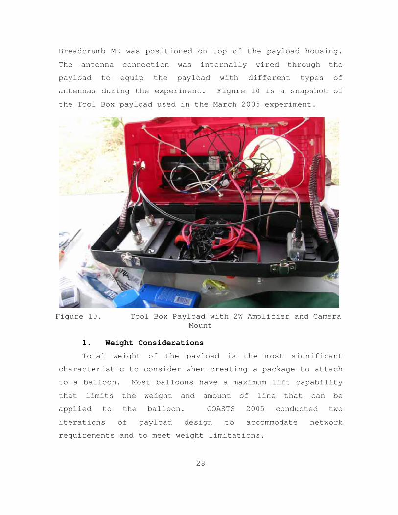
Breadcrumb ME was positioned on top of the payload housing.
The antenna connection was internally wired through the
payload to equip the payload with different types of
antennas during the experiment. Figure 10 is a snapshot of
the Tool Box payload used in the March 2005 experiment.
Figure 10. Tool Box Payload with 2W Amplifier and Camera Mount
1. Weight Considerations
Total weight of the payload is the most significant
characteristic to consider when creating a package to attach
to a balloon. Most balloons have a maximum lift capability
that limits the weight and amount of line that can be
applied to the balloon. COASTS 2005 conducted two
iterations of payload design to accommodate network
requirements and to meet weight limitations.

29
The minimum lift of the Sky-Doc balloon, with no wind,
is 16.8 pounds. The March 2005 experiment used a Tool Box
payload that weighed 17.1 pounds. This weight was too heavy
for balloon operations. Minor changes were made to the
payload in order to decrease the weight to 13 pounds. At 75
percent of the minimum lift requirement, the Sky-Doc balloon
successfully ascended to 1,500 feet with wind speeds at less
than 5 knots.
In the May 2005 iteration of the experiment, a smaller
package was used for the payload. The payload consisted of
a small, fire-retardant box that weighed approximately two
pounds. A Supercrumb, a Breadcrumb XL equivalent, was used
instead of the Breadcrumb ME. The payload also housed a
smaller Pan-Zoom-Tilt (PZT) camera to provide video
streaming. The total weight of this payload was nine pounds
(including two UB 2590 battery packs). The Sky-Doc balloon
handled this weight adequately.
The most significant changes to the payload dealt with
consolidating the power supply to one battery pack and
reducing the size of the camera. The UB 2590 is a military
standard, lithium-ion (Li-Ion), direct current (DC) battery.
The operational voltage range is from 15 to 30 volts DC.
Applying a single UB 2590 cell to the payload provided a
single power source for all components of the payload. The
total operational time of the payload increased to 10 to 12
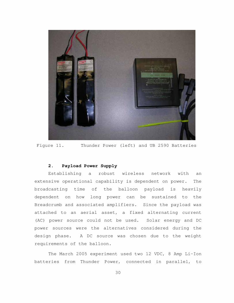
hours. Figure 11 shows the Thunder Power and UB 2590
batteries used for the March and May experiments,
respectively.
30
Figure 11. Thunder Power (left) and UB 2590 Batteries
2. Payload Power Supply
Establishing a robust wireless network with an
extensive operational capability is dependent on power. The
broadcasting time of the balloon payload is heavily
dependent on how long power can be sustained to the
Breadcrumb and associated amplifiers. Since the payload was
attached to an aerial asset, a fixed alternating current
(AC) power source could not be used. Solar energy and DC
power sources were the alternatives considered during the
design phase. A DC source was chosen due to the weight
requirements of the balloon.
The March 2005 experiment used two 12 VDC, 8 Amp Li-Ion
batteries from Thunder Power, connected in parallel, to
31
power the payload camera and amplifier. The Breadcrumb
power source was a 9 VDC, 5.4 Amp Li-Ion battery. The total
weight of the three batteries was approximately three
pounds. Using three battery packs created operational
variables that lessened the operational efficiency of the
Tool Box payload. Inconsistent battery discharge rates
contributed to most of the inefficiencies. At one point
during the March experiment, the Breadcrumb was still
connected to the network, but the camera video could not be
seen. Upon investigation, the camera power source was found
to be totally depleted. The Breadcrumb battery had an
average operational time of eight to ten hours whereas the
separate Li-Ion batteries maintained power to the rest of
the system for six to eight hours.
In the May experiment, the use of one power source
eliminated the uneven battery discharge problem. The UB
2590 was able to sustain power to all components of the
payload. The only addition to the schematic of the payload
was the use of voltage regulators to limit the 15VDC battery
voltage to 10VDC needed for the camera and cooling units.
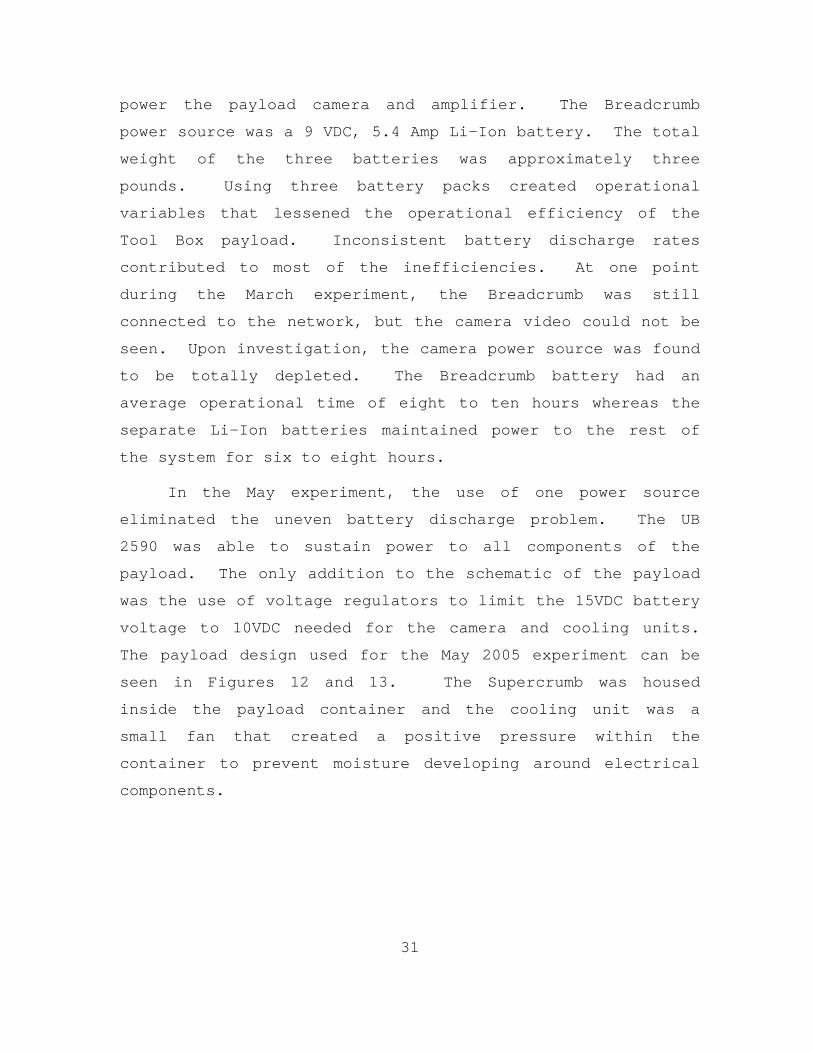
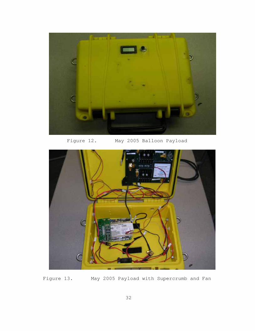
The payload design used for the May 2005 experiment can be
seen in Figures 12 and 13. The Supercrumb was housed
inside the payload container and the cooling unit was a
small fan that created a positive pressure within the
container to prevent moisture developing around electrical
components.
32
Figure 12. May 2005 Balloon Payload
Figure 13. May 2005 Payload with Supercrumb and Fan
33
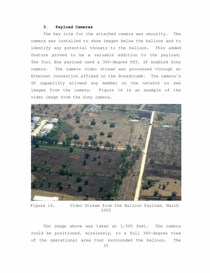
3. Payload Cameras
The key role for the attached camera was security. The
camera was installed to show images below the balloon and to
identify any potential threats to the balloon. This added
feature proved to be a valuable addition to the payload.
The Tool Box payload used a 360-degree PZT, IP enabled Sony
camera. The camera video stream was processed through an
Ethernet connection affixed on the Breadcrumb. The camera’s
IP capability allowed any member on the network to see
images from the camera. Figure 14 is an example of the
video image from the Sony camera.
Figure 14. Video Stream from the Balloon Payload, March 2005
The image above was taken at 1,500 feet. The camera
could be positioned, wirelessly, to a full 360-degree view
of the operational area that surrounded the balloon. The
34
most significant limitation with video from the payload
concerns stabilization. Image stability is directly
dependent upon balloon stability and since the balloon
consistently changed position with wind direction, stable
video images were rare at best.
Another concern with equipping a camera to the payload
is weather. Most cameras need all weather housings to
operate outdoors. The extra housing added an additional
eight pounds to the first payload design. As mentioned
previously, the March 2005 payload had to be altered in
order to commence flight operations. The alteration
consisted of removing the all-weather housing and the Sony
camera operated successfully without the housing;
fortunately, precipitation was minimal during the
experiment. It would be prudent for future designs to
include and to account for all weather housings or cameras
that can operate in areas of high moisture.
Digital video creates a potentially significant
bandwidth issue for the network. During the March 2005
experiment, a large part of the network bandwidth consisted
of video streams from multiple cameras. Since any camera
could be accessed by any member of the network, the flow of
information was hindered due to multiple nodes exploring the
camera images. Video streaming throughput slowed to one
frame per second when more than five members tried to
control the camera. This problem created a new camera
management requirement that only the COC could control the
camera during operations. This also established the need
35
for a multi-cast camera to allow multiple users to see
camera images without creating a bottleneck to the remaining
network.
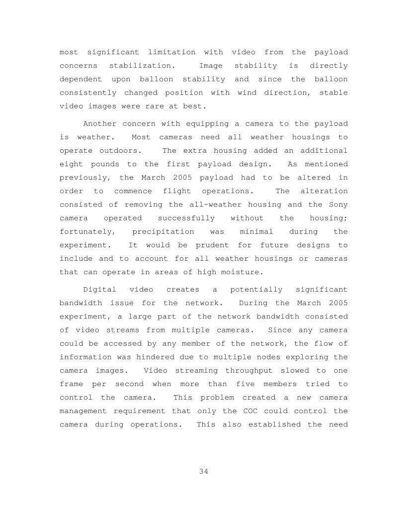
To remedy video streaming problems during the May 2005
experiment, a multi-cast, IP enabled, MPEG-4 camera from
4XEM replaced the Sony camera. This particular camera still
has a PZT feature, but the range of motion is limited to 120
degrees horizontally and 60 degrees vertically. The 4XEM
camera has a smaller optical zoom capability and the image
size was limited. The key features of this camera are size
and weight. Its dimensions are 5” X 4” and it weighs 1.2
pounds.
Both cameras were very durable and remained operational
even after being slammed into the ground from a height of 75
feet, exposed to extreme rotational forces, and soaked with
torrential rains. Figure 15 depicts the 4XEM and Sony
cameras, side by side, to show the difference in relative
size.
Figure 15. 4XEM Camera (left) and Sony Camera
36
C. LESSONS LEARNED
During both the March and May experiments, many lessons
involving the Breadcrumbs and other network equipment were
learned. In general, the most significant issue concerned
the range capability of the Breadcrumbs.
As stated in paragraph A, the Breadcrumbs were to be
capable of transmitting 802.11b signals at distances of up
to .5 miles, for the smaller designs, and almost ten miles
for the XL model. These distances were found to be
considerably less during actual operation. The initial mesh
network was created to cover an approximate area of ten
square miles. The individual Breadcrumbs were positioned no
more than .25 miles from each other. The quality of the
network was never consistent. The best links, at 11 Mbps,
only lasted for two hour durations. Different areas of the
network would lose signals for no apparent reason. Thus the
range of the network was reduced to less than 300 square
yards. Even at this distance, the available throughput
would still drop to 2Mbps without notice. These problems
were attributed to many variables, which included high
temperatures, humidity, improper placement of Breadcrumbs,
and antenna placement. A detailed description of the
lessons learned for the network equipment is provided in
Appendix C.
37
V. ANTENNAE
A. PAYLOAD ANTENNAE
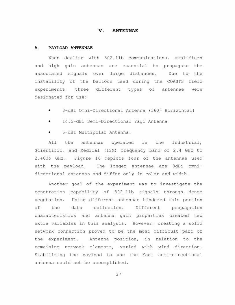
When dealing with 802.11b communications, amplifiers
and high gain antennas are essential to propagate the
associated signals over large distances. Due to the
instability of the balloon used during the COASTS field
experiments, three different types of antennae were
designated for use:
• 8-dBi Omni-Directional Antenna (360° Horizontal)
• 14.5-dBi Semi-Directional Yagi Antenna
• 5-dBi Multipolar Antenna.
All the antennas operated in the Industrial,
Scientific, and Medical (ISM) frequency band of 2.4 GHz to
2.4835 GHz. Figure 16 depicts four of the antennae used
with the payload. The longer antennae are 8dBi omni-
directional antennas and differ only in color and width.
Another goal of the experiment was to investigate the
penetration capability of 802.11b signals through dense
vegetation. Using different antennae hindered this portion
of the data collection. Different propagation
characteristics and antenna gain properties created two
extra variables in this analysis. However, creating a solid
network connection proved to be the most difficult part of
the experiment. Antenna position, in relation to the
remaining network elements, varied with wind direction.
Stabilizing the payload to use the Yagi semi-directional
antenna could not be accomplished.
38
Figure 16. Yagi (left), Omni-Directional and Multi-Polar Antennae
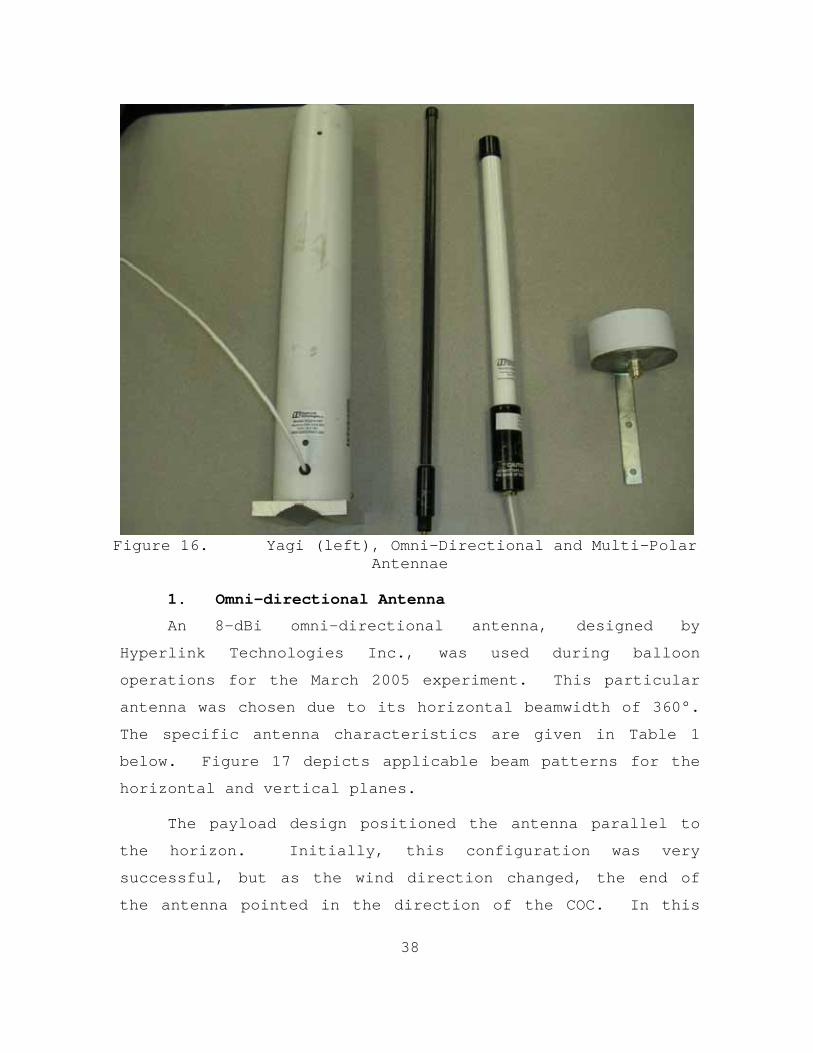
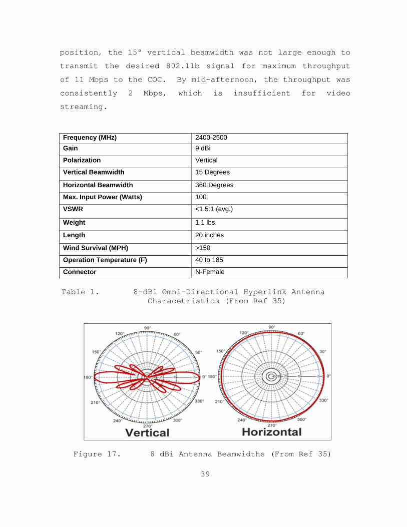
1. Omni-directional Antenna
An 8-dBi omni-directional antenna, designed by
Hyperlink Technologies Inc., was used during balloon
operations for the March 2005 experiment. This particular
antenna was chosen due to its horizontal beamwidth of 360°.
The specific antenna characteristics are given in Table 1
below. Figure 17 depicts applicable beam patterns for the
horizontal and vertical planes.
The payload design positioned the antenna parallel to
the horizon. Initially, this configuration was very
successful, but as the wind direction changed, the end of
the antenna pointed in the direction of the COC. In this
39
position, the 15° vertical beamwidth was not large enough to
transmit the desired 802.11b signal for maximum throughput
of 11 Mbps to the COC. By mid-afternoon, the throughput was
consistently 2 Mbps, which is insufficient for video
streaming.
Frequency (MHz) 2400-2500 Gain 9 dBi
Polarization Vertical
Vertical Beamwidth 15 Degrees
Horizontal Beamwidth 360 Degrees
Max. Input Power (Watts) 100
VSWR <1.5:1 (avg.)
Weight 1.1 lbs.
Length 20 inches
Wind Survival (MPH) >150
Operation Temperature (F) 40 to 185
Connector N-Female Table 1. 8-dBi Omni-Directional Hyperlink Antenna
Characetristics (From Ref 35)
Figure 17. 8 dBi Antenna Beamwidths (From Ref 35)
40
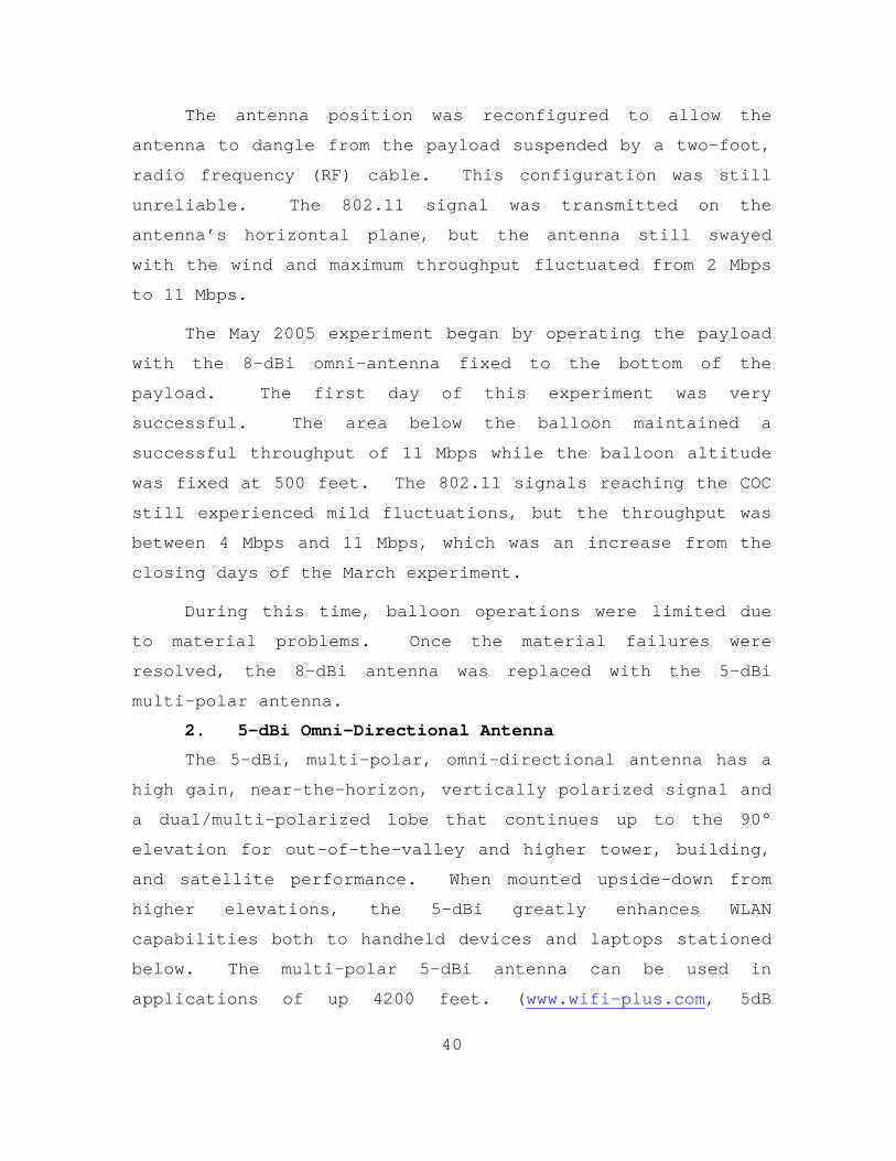
The antenna position was reconfigured to allow the
antenna to dangle from the payload suspended by a two-foot,
radio frequency (RF) cable. This configuration was still
unreliable. The 802.11 signal was transmitted on the
antenna’s horizontal plane, but the antenna still swayed
with the wind and maximum throughput fluctuated from 2 Mbps
to 11 Mbps.
The May 2005 experiment began by operating the payload
with the 8-dBi omni-antenna fixed to the bottom of the
payload. The first day of this experiment was very
successful. The area below the balloon maintained a
successful throughput of 11 Mbps while the balloon altitude
was fixed at 500 feet. The 802.11 signals reaching the COC
still experienced mild fluctuations, but the throughput was
between 4 Mbps and 11 Mbps, which was an increase from the
closing days of the March experiment.
During this time, balloon operations were limited due
to material problems. Once the material failures were
resolved, the 8-dBi antenna was replaced with the 5-dBi
multi-polar antenna.
2. 5-dBi Omni-Directional Antenna
The 5-dBi, multi-polar, omni-directional antenna has a
high gain, near-the-horizon, vertically polarized signal and
a dual/multi-polarized lobe that continues up to the 90°
elevation for out-of-the-valley and higher tower, building,
and satellite performance. When mounted upside-down from
higher elevations, the 5-dBi greatly enhances WLAN
capabilities both to handheld devices and laptops stationed
below. The multi-polar 5-dBi antenna can be used in
applications of up 4200 feet. (www.wifi-plus.com, 5dB
41
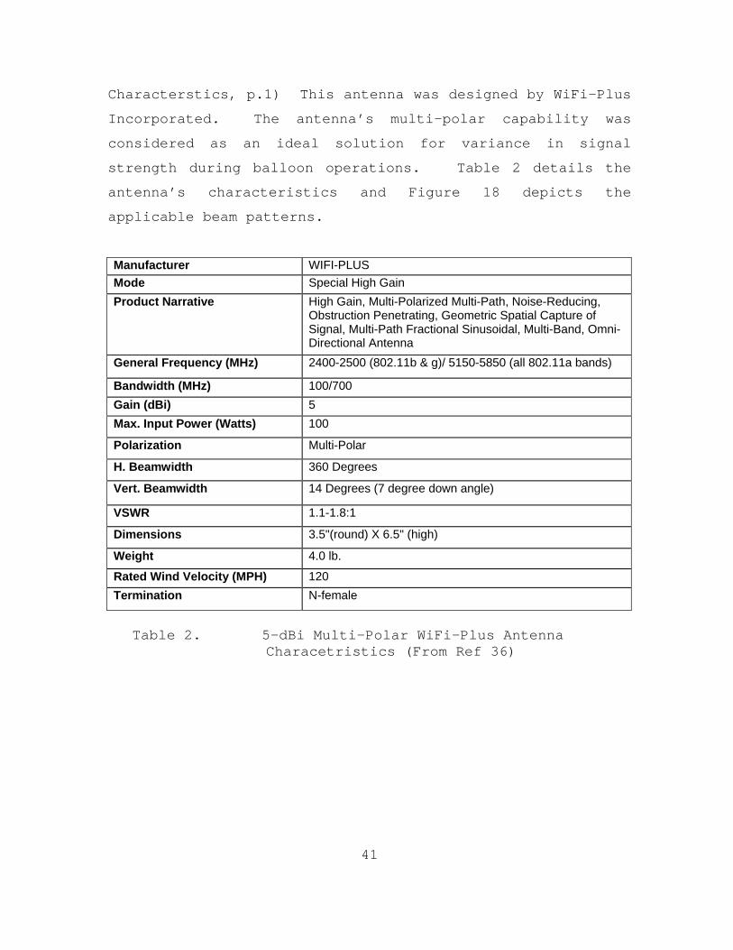
Characterstics, p.1) This antenna was designed by WiFi-Plus
Incorporated. The antenna’s multi-polar capability was
considered as an ideal solution for variance in signal
strength during balloon operations. Table 2 details the
antenna’s characteristics and Figure 18 depicts the
applicable beam patterns.
Manufacturer WIFI-PLUS Mode Special High Gain Product Narrative High Gain, Multi-Polarized Multi-Path, Noise-Reducing,
Obstruction Penetrating, Geometric Spatial Capture of Signal, Multi-Path Fractional Sinusoidal, Multi-Band, Omni-Directional Antenna
General Frequency (MHz) 2400-2500 (802.11b & g)/ 5150-5850 (all 802.11a bands)
Bandwidth (MHz) 100/700 Gain (dBi) 5 Max. Input Power (Watts) 100
Polarization Multi-Polar
H. Beamwidth 360 Degrees
Vert. Beamwidth 14 Degrees (7 degree down angle)
VSWR 1.1-1.8:1
Dimensions 3.5"(round) X 6.5" (high)
Weight 4.0 lb.
Rated Wind Velocity (MPH) 120 Termination N-female
Table 2. 5-dBi Multi-Polar WiFi-Plus Antenna
Characetristics (From Ref 36)
42
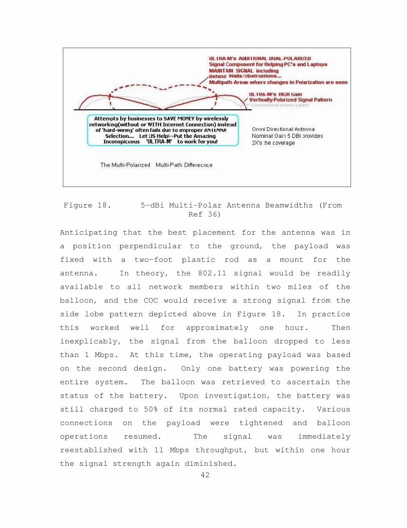
Figure 18. 5-dBi Multi-Polar Antenna Beamwidths (From Ref 36)
Anticipating that the best placement for the antenna was in
a position perpendicular to the ground, the payload was
fixed with a two-foot plastic rod as a mount for the
antenna. In theory, the 802.11 signal would be readily
available to all network members within two miles of the
balloon, and the COC would receive a strong signal from the
side lobe pattern depicted above in Figure 18. In practice
this worked well for approximately one hour. Then
inexplicably, the signal from the balloon dropped to less
than 1 Mbps. At this time, the operating payload was based
on the second design. Only one battery was powering the
entire system. The balloon was retrieved to ascertain the
status of the battery. Upon investigation, the battery was
still charged to 50% of its normal rated capacity. Various
connections on the payload were tightened and balloon
operations resumed. The signal was immediately
reestablished with 11 Mbps throughput, but within one hour
the signal strength again diminished.
43
Unfortunately balloon operations could not continue
after this experiment due to the unexplainable failure of
the balloon itself. Only two antennae were tested for
802.11b propagations during days of balloon operations.
Neither had the necessary signal strength nor durability to
analyze the capability of 2.4 GHz signal to penetrate a
highly vegetated environment.
One significant data point was taken while using the
multi-polar antenna at a fixed ground location. The antenna
was positioned on top of a 20-foot light pole. When the
accompanied Breadcrumb was turned on, the network instantly
connected with a data throughput of 11 Mbps between all
nodes. This was quite impressive because the signal went
through 50 yards of underbrush and a tree-line, connecting
the COC to the local network, transmitting to the balloon,
and connecting every local unit within 300 yards to the main
network. Again, this connection did not last long,
approximately 15 minutes, but the signal lasted long enough
to show the capability of this antenna.
This same antenna was later tested in a closed environment
which determined that the antenna had an intermittent flaw
that could not be corrected. Due to the irreparable damage
to the balloon and the lack of time required to replace the
antenna, further experiments with this antenna could not be
conducted.
3. Yagi Antenna
Although the Yagi antenna was not used during balloon
operations, the experiment did find an application for this
type of antenna when creating a tactical network. These
antennae worked adequately when affixed to a stationary mast
or object within LOS of one another.
44
As illustrated in Chapter II, the COC used a wireless
link to send data to the Wing 2 Communications Building. A
Breadcrumb was staged at each link termination point and
equipped with a 14.5 dBi Yagi antenna. These antennae were
placed on the roof of each facility and the distance between
the buildings was approximately 1,000 feet. While operating
the antennae with the Breadcrumbs, the signals were found to
be intermittent. When the Breadcrumbs were replaced by Data
Link routers, the 802.11 signal was very strong for the
remainder of the operation. The Yagis used for COASTS 2005
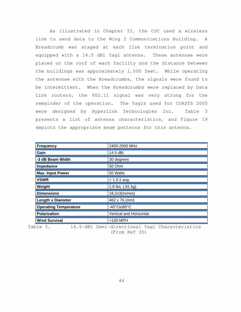
were designed by Hyperlink Technologies Inc. Table 3
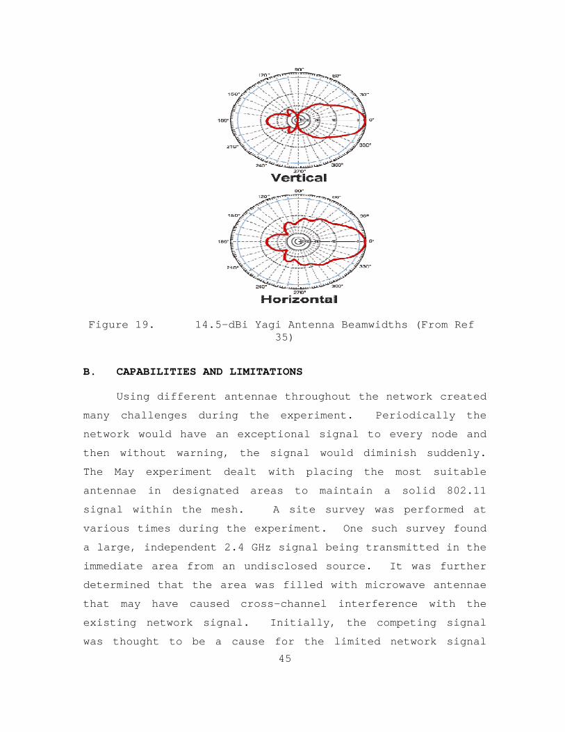
presents a list of antenna characteristics, and Figure 19
depicts the appropriate beam patterns for this antenna.
Frequency 2400-2500 MHz
Gain 14.5 dBi
-3 dB Beam Width 30 degrees
Impedance 50 Ohm
Max. Input Power 50 Watts
VSWR < 1.5:1 avg.
Weight 1.8 lbs. (.81 kg)
Dimensions 18.2x3(inches)
Length x Diameter 462 x 76 (mm)
Operating Temperature -40°Cto85°C
Polarization Vertical and Horizontal
Wind Survival >150 MPH Table 3. 14.5-dBi Semi-directional Yagi Characteristics
(From Ref 35)
45
Figure 19. 14.5-dBi Yagi Antenna Beamwidths (From Ref 35)
B. CAPABILITIES AND LIMITATIONS
Using different antennae throughout the network created
many challenges during the experiment. Periodically the
network would have an exceptional signal to every node and
then without warning, the signal would diminish suddenly.
The May experiment dealt with placing the most suitable
antennae in designated areas to maintain a solid 802.11
signal within the mesh. A site survey was performed at
various times during the experiment. One such survey found
a large, independent 2.4 GHz signal being transmitted in the
immediate area from an undisclosed source. It was further
determined that the area was filled with microwave antennae
that may have caused cross-channel interference with the
existing network signal. Initially, the competing signal
was thought to be a cause for the limited network signal
46
strength but after further investigation, this signal was
operating at a lower power level than the COASTS network.
The main signal analysis tool used to perform the site
survey was Airopeek, installed on a laptop, while the
receiver was an 802.11b/g wireless card from Oronoco. The
necessity to conduct a thorough site survey is part of the
lessons learned for COASTS 2005.
Another problem with the antennae used for this
experiment was the differing polarizations of the antennae
itself. During the March experiment, the COC used a one-
foot, horizontally polarized, flat-panel antenna, focused in
the direction of the balloon while the balloon used a
vertically polarized antenna. These two antennae were not
compatible. The COC antenna was changed to an omni-
directional, vertically polarized antenna, and signal
reception improved. In some cases, the antennae were not in
direct LOS of other nodes and environmental interference,
such as trees and shrubs, blocked the signal. Many of these
nodes were subsequently relocated to improve connections to
the balloon and the COC.
The most effective configuration occurred when the
omni-directional antenna was affixed to the balloon, all
ground nodes, and the COC. However, the range of the 802.11
network was still limited to a maximum of 300 yards between
each Breadcrumb. This distance was much lower than expected
based on testing at Fort Ord, California. In the end, the
network was reduced to a 300-square yard area. Video
streaming and text was readily available within this smaller
meshed network.
47
At the conclusion of COASTS 2005, many of the antenna
problems were addressed. A key lesson learned was that
antenna polarization characteristics must be known prior to
use. Evidence showed that many of the signal failures were
caused by using antennae with differing polarizations.
C. LESSONS LEARNED
A number of the lessons learned dealt with proper
antenna positioning and configuration. Long hours were
spent placing Breadcrumbs within LOS, but antenna
polarization was not accounted for until much later in the
experiment. Another significant finding was that the
antenna had to be placed at least two feet away from the
Breadcrumb unit. Each Breadcrumb ME uses two antennae, one
for receiving 802.11 signals and one for transmitting. Due
to Breadcrumb design, when the external antenna was placed
next to the unit, the 802.11 signals from the two cards
within the Breadcrumb created interfering transmissions.
This problem was addressed during the last two days of the
May experiment. The antennae were placed four feet above
each unit and signal processing between Breadcrumbs rose
significantly. A complete list of lessons learned is
provided in Appendix C.

48
THIS PAGE INTENTIONALLY LEFT BLANK
49
VI. CONCLUSION AND RECOMMENDATIONS
A. CONCLUSION
The development of a reliable, mobile, wireless network
is very important in supplying the soldier real-time
information. The technologies used in this experiment
provided a base-line in expanding the investigation of COTS
wireless systems in promulgating digital data to mobile
assets.
The main objective of this experiment, to develop a
reliable, aerial, access point with helium-filled balloons
and current 802.11b Wi-Fi technology, was not completely
investigated. The unforeseen damage to the balloon and
limited network availability did not allow for the full
determination of 802.11b signals to penetrate the jungle
environment. The COASTS 2005 experiment did find that the
balloon was an adequate platform to distribute real-time
digital information to multiple network assets
simultaneously. While the Breadcrumb was more than capable
of providing 802.11b signals with 11 Mbps throughput, the
signal was not reliable throughout the experiment.
The limiting factor in this network was found to be
antenna configuration. The antennae used during the
experiment had different polarizations, which hampered
network development. The second design of the balloon
payload was a tremendous upgrade. The payload’s power
consumption was minimal and it provided a reliable 802.11b
signal within the local operating area, which included a 500
yard radius beneath the balloon. The multi-polar antenna
is optimum for this type of application. In order to
50
accommodate multiple network users, this antenna must be
employed to minimize antenna compatibility problems.
However, it was determined that the 802.11b technology
severely limits throughput. With 54 Mbps throughput,
802.11g technology seems better suited to represent the
future of wireless networking. Additionally, the rising
interest in 802.16 technology and its experienced
reliability, makes this technology another key component to
investigate for tactical networks.
B. FUTURE PROJECTS
COASTS 2006 will research further developments in
tactical wireless networks consisting of 802.11g and 802.16
fixed and mobile based products. The determination to use
802.11g products was due to the minimum throughput realized
during the COASTS 2005 field experiments. At 11 Mbps, the
802.11b technology is not robust enough to handle continuous
video streaming from multiple cameras and maintain the
required data flow to supply the necessary information to
air and ground units in a timely manner.
Several variables must be addressed to overcome the
limitations in using a lighter-than-air vehicle as a
wireless relay. These include: 1) identifying a suitable
antenna with the appropriate gain and polarization
characteristics to distribute 802.11 signals over a large
distance, 2) stabilizing the balloon at determined heights
to minimize fluctuations in antenna position, and 3)
overcoming the limitations in data flow found in 802.11b
based products.
Even though the network developed during the COASTS
2005 experiment did not produce the desired results, it did
51
provide enough information to conclude that a mobile network
can be established with minimal equipment and that balloons
provide an inexpensive over-the-horizon (OTH) platform to
process wireless data. Further research is needed to refine
the deployment and integration of balloons in creating
mobile 802.11 networks. Balloons have the potential to
function as a reliable, logistically efficient, highly
mobile, wireless asset.
COASTS 2006 will attempt to create an 802.11g mesh
network using a mesh network device, similar to the
Breadcrumb, engineered by ITT and supplied by Mercury Data
Systems. The 2006 experiment will continue wireless
research on the use of lighter-than-air vehicles to process
digital data over large distances. The network will consist
of four balloons equipped with mesh network kits and multi-
polar antennae. The balloons will serve as the perimeter
devices for the network and will also be tasked to conduct
surveillance and targeting within a changing environment
that consists of mountains, rivers and heavy vegetation.
The site for COASTS 2006 is in Chiang Mai, Thailand
specifically the Mae Ngat Dam area. Multiple organizations
have confirmed participation in this future operation to
include:
• Thailand Defense Research and Development Office
• Royal Thai Air Force
• Thailand National Security Council
• Thailand Interagency Intelligence Fusion Center
• Naval Postgraduate School
52
• U.S. Special Operations Command (USSOCOM)
• NPS Maritime Domain Protection Research Group
• Joint Inter Agency Task Force-West
• Joint U.S. Military Advisory Group Thailand.
COASTS 2006 will also include establishing a Global
Positioning System capability for each balloon as well as
other ground and air assets.
C. RECOMMENDATIONS
Future experimentation should include the sole use of
multi-polar antennae. Antennae similar to the 5-dBi, multi-
polar described in Chapter V will minimize the difficulties
in network connectivity seen during COASTS 2005.
Multiple balloons must be used to fully research the
capabilities of 802.11 signals within a hot, humid and
densely vegetated environment. Using one balloon limited
the necessary data collection. Having multiple balloons
will create the needed redundancy in network connectivity
and can expand research efforts by allowing opportunities to
experiment with different wireless platforms simultaneously.
Alternatives to 802.11b-based products should also be
included in follow-on experiments. 802.11g and 802.16
products might provide the needed signal propagation and
data throughput to successfully process the intensive video
streaming required for situational awareness.
In summary, research with wireless platforms will
continue to be the focus for the COASTS project. Through
this field experimentation program, a wireless surveillance

53
and targeting package will be created and refined to send
consistent, viable, real-time information to the war-fighter
as well as local, regional and strategic decision makers.

54
THIS PAGE INTENTIONALLY LEFT BLANK
55
APPENDIX A. COASTS 2005 CONCEPT OF OPERATIONS
COASTS
Thailand Demo (May 2005)
Concept of Operations
NAVAL
POSTGRADUATE
SCHOOL
MONTEREY, CALIFORNIA
11 March 2005
56
TABLE OF CONTENTS
DISTRIBUTION STATEMENT ..............................II TABLE OF CONTENTS ..................................III LIST OF FIGURES .....................................VI LIST OF ACRONYMS ...................................VII 1.0 PURPOSE.........................................1 1.1 Background........................................1 1.1.1 TNT FE Specifics................................1 1.1.2 TNT FE Limitations..............................2 1.1.2.1 Sensitivities with Foreign Observers/Participants..........................2 1.1.2.2 Meteorological,Hydrographic and Geographic Considerations.......................2 1.1.3 COASTS..........................................2 1.1.3.1 Purpose.......................................2 1.1.3.2 Strategy......................................2 1.2 References........................................2 1.3 Scope.............................................3 2.0 OVERVIEW..........................................4 2.1 Current Situation. ...............................4 2.2 System Summary....................................4 2.3 Capabilities......................................4 2.4 Major Components..................................5 2.5 Configurations....................................8 3.0 CONCEPT OF OPERATIONS. ...........................9 3.1 Users.............................................9 3.2 COASTS SUPPORT FOR PRINCIPAL MISSION AREAS........9 3.2.1 Thailand Requirements..........................10 3.2.1.1 Thailand Requirement Overview................10 3.2.1.2 COASTS Support to Thai Requirements....................................11 3.3 COASTS Implementation and Objectives.............11 3.3.1 Phased Approach................................11 3.3.2 Phase I - Work Up..............................11 3.3.3 Phase II – Movement to Site ...................12 3.3.4 Phase III – May 2005 Demonstration.............12
57
3.3.4.1 802.11 (2.4 GHz) End-user Tactical Network...........................13 3.3.4.2 802.16 (5.8 GHz) Backbone....................13 3.3.4.3 Satcom link..................................14 3.3.4.4 Wearable Computing...........................14 3.3.4.5 Cyber Defense UAV............................14 3.3.4.6 Thai AU-23...................................14 3.3.4.7 Situational Awareness (SA) Agents............14
3.3.4.8 Tactical Operations Center / Network Operations Center(NOC).......................14
3.3.5 Future Items and Other Capabilitie.............15 3.3.6 COASTS Critical Event Schedule.................16 3.4 Critical Operational Issues (COIS),..............16 3.5 Measures of Effectiveness (MOE) and Measures of Performance (MOP)...................17 4.0 MANAGEMENT STRATEGY. ............................18 4.1 Participating Organizations, Roles and Responsibilities...........................18 4.1.1 COASTS Oversight Group.........................18 4.1.2 NPS Principal Investigator (PI). ..............18 4.1.3 NPS Operational Manager (OM)...................18 4.1.4 NPS Technical Manager (TM).....................18 4.1.5 Participating Test Organizations...............20 4.2 Risk Assessment, Management and Mitigation.......20 4.3 Development Strategy.............................20 5.0 TRAINING, LOGISTIC AND SAFETY. ..................21 5.1 Training.........................................21 5.2 Logistics........................................21 5.2.1 COASTS Set-Up and Demo. .......................21 5.3 Safety...........................................21 6.0 MODIFICATIONS....................................23 7.0 POINTS OF CONTACT ...............................24 7.1 Naval Postgraduate School........................24 7.2 JUSMAGTHAI.......................................24 7.3 US Pacific Command...............................24 7.4 Royal Thai Armed Forces..........................25
58
APPENDIX A1. NETWORK TOPOLOGY........................A-1 APPENDIX A2. WIRELESS 802.11 NETWORK (BREADCRUMBS) ..B-3 APPENDIX A3. WIRELESS 802.16 NETWORK (OFDM)..........C-1 APPENDIX A4. AVIATION OPERATIONS ....................D-1 APPENDIX A5. AU-23 ..................................E-1 APPENDIX A6. SEARCHER UAV............................F-1 APPENDIX A7. CYBER DEFENSE ..........................G-1 APPENDIX A8. MINI UAV HELO ..........................H-1 APPENDIX A9. SONY CAMERA SYSTEM .....................I-1 APPENDIX A10. SENSOR GRID ............................J-1 APPENDIX A11. PDAS FORM INTER-4 TACTICOMP.............K-1 APPENDIX A12. FUNCTIONAL AREAS .......................L-1 APPENDIX A13. THESIS RESEARCH ........................M-1 APPENDIX A14. MEASURES OF PERFORMANCE ................N-1
59
LIST OF FIGURES
Figure 1. Thai Mobile Command Platform ...............5
Figure 2. Tethered Balloon ...........................6
Figure 3. INTER-4 Tacticomp Handheld GPS Enabled
Networked Situational Awareness Tools.......7
Figure 4. COASTS Demonstration Configuration ........13
Figure 5. Critical Events Schedule...................16
Figure 6. Risk Matrix ..............................20
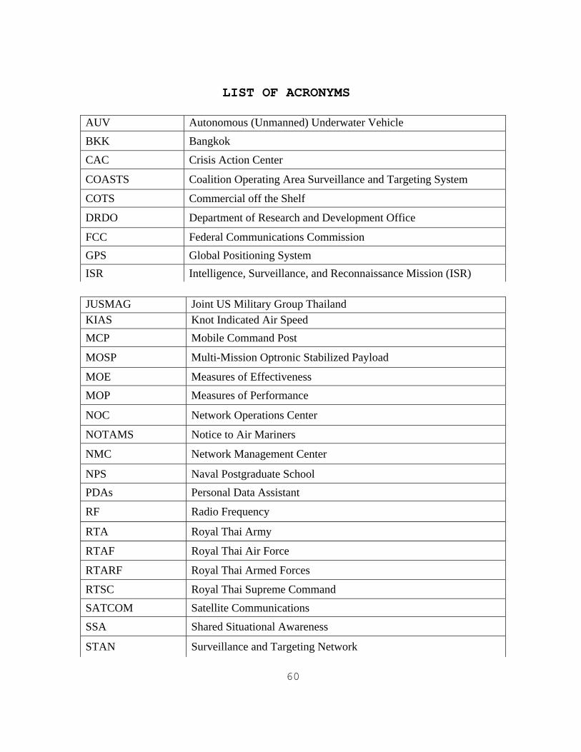
60
LIST OF ACRONYMS
JUSMAG Joint US Military Group Thailand KIAS Knot Indicated Air Speed MCP Mobile Command Post
MOSP Multi-Mission Optronic Stabilized Payload
MOE Measures of Effectiveness MOP Measures of Performance
NOC Network Operations Center
NOTAMS Notice to Air Mariners
NMC Network Management Center
NPS Naval Postgraduate School PDAs Personal Data Assistant
RF Radio Frequency
RTA Royal Thai Army
RTAF Royal Thai Air Force
RTARF Royal Thai Armed Forces
RTSC Royal Thai Supreme Command SATCOM Satellite Communications
SSA Shared Situational Awareness
STAN Surveillance and Targeting Network
AUV Autonomous (Unmanned) Underwater Vehicle BKK Bangkok
CAC Crisis Action Center
COASTS Coalition Operating Area Surveillance and Targeting System
COTS Commercial off the Shelf
DRDO Department of Research and Development Office
FCC Federal Communications Commission GPS Global Positioning System ISR Intelligence, Surveillance, and Reconnaissance Mission (ISR)

61
TNT FE Tactical Network Topology Field Experiment TOC Tactical Operations Center UAV Unmanned Aerial Vehicle WLAN Wireless Local Area Network WOT War on Terror
62
1.0 Purpose
This document describes the Concept of Operations (CONOPS) for the development and implementation of a Naval Postgraduate School (NPS) research program entitled Coalition Operating Area Surveillance & Targeting System (COASTS). COASTS support U.S. Pacific Command (USPACOM), Joint U.S. Military Advisor’s Group Thailand (JUSMAGTHAI), Naval Postgraduate School, and Thailand Royal Thai Supreme Command (RTSC), Royal Thai Armed Forces (RTARF), and the Thai Department of Research & Development Office (DRDO) science and technology research requirements relating to theater security, host nation security, and the War On Terror (WOT).
This CONOPS is primarily intended for use by the Naval Postgraduate School and USPACOM management team and participating contractors and coalition partners. However, it may also be used by other Department of Defense (DoD) organizations when applicable. The research and development of COASTS is described in this document as well as the proposed timetable for a cap-stone demonstration in May 2005 in Thailand.
1.1 BACKGROUND
The COASTS proposed coalition field experimentation concept is modeled after a very successful ongoing NPS-driven field experimentation program previously known as Surveillance and Targeting Network (STAN) and now called the Tactical Network Topology Field Experiment (TNT FE). NPS, in cooperation with U.S. Special Operations Command (USSOCOM) and several contractors, has been engaged in a Research and Development (R&D) program entitled STAN since FY2002. The program was initiated in support of a USSOCOM requirement for integrating emerging wireless local area network (WLAN) technologies with surveillance and targeting hardware/software systems to augment Special Operations Forces missions. TNT FE has grown significantly since inception to include 10-12 private sector companies demonstrating new hardware/software capabilities, several DoD organizations (led by NPS) introducing operational and tactical surveillance and targeting requirements, as well as other universities contributing solutions.
63
1.1.1 TNT FE Specifics
TNT FE occurs quarterly as a 1-2 week long complex experiment comprising 810 NPS faculty members, 20-30 NPS students, and representatives from multiple private companies, DoD and US government agencies. Major TNT FE objectives are as follows:
Provide an opportunity for NPS students and faculty to experiment/evaluate with the la test technologies which have potential near-term application to the warfighter.
Leverage operational experience of NPS students and faculty
Provide military, national laboratories, contractors, and civilian universities an opportunity to test and evaluate new technologies in operational environments
Utilize small, focused field experiments with well-defined measures of performance for both the technologies and the operator using the technologies
Implement self-forming / self-healing, multi-path, ad-hoc network w/sensor cell, ground, air, SATCOM network components
1.1.2 TNT FE Limitations
1.1.2.1 Sensitivities with Foreign Observers/ Participants
Certain hardware, software, and tools/tactics/procedures (TTP’s) implemented at TNT FE are classified or operationally sensitive, and as a result TNT FE sponsors have not agreed to foreign military partnerships. Despite DOD requirements to operate in coalition environments, to strengthen relationships with foreign military partners, and to execute operations globally, TNT FE remains primarily a US-only event.
1.1.2.2 Meteorological, Hydrographic, & Geographic Considerations
All TNT FE have been conducted at NPS’s facilities in the Monterey California area. This vegetation and climate is not representative of the Pacific Area of Responsibility (AOR)—a likely deployment location for these tactical or operational WLAN and surveillance/targeting technologies. Higher temperatures and humidity, as well as denser
64
vegetation in areas like Thailand and Singapore, will likely create WLAN and sensor performance problems.
1.1.3 COASTS
1.1.3.1 Purpose
COASTS will leverage and integrate the technological expertise of NPS’s education and research resources with the science and technology (and potential operational requirements) of the RTSC using WLAN technologies to fuse and display information from air and ground sensors to a real-time, tactical, coalition enabled command and control center. The timeline for the planning and execution of this demonstration is provide in greater detail later in this document. An additional benefit of the COASTS project will be to demonstrate USPACOM commitment to foster stronger multi-lateral relations in the area of technology development and coalition warfare with key Pacific AOR allies in the WOT, as the May 2005 demonstration will have observers from Australia, Singapore, Thailand, U.S., and Japan.
1.1.3.2 Strategy
The Thailand based COASTS demonstration will serve as a mobile field test bed environment for R&D, integration, operational testing, and field validation of several emerging wireless technologies and equipment suites. The demonstration will provide key Thai military leadership an opportunity to observe potential capabilities to support ongoing RTARF missions along the Mynamar border or in peacekeeping missions in Southern Thailand.
1.2 REFERENCES
1. Joint Doctrine for Information Operations, Joint Pub 3-13, 9 October 1998
2. Joint Doctrine for Command and Control Warfare (C2W), Joint Pub 3-13, 7 February 1996
3. Joint Doctrine for Operations Security, Joint Pub 3-54, 24 January 1997
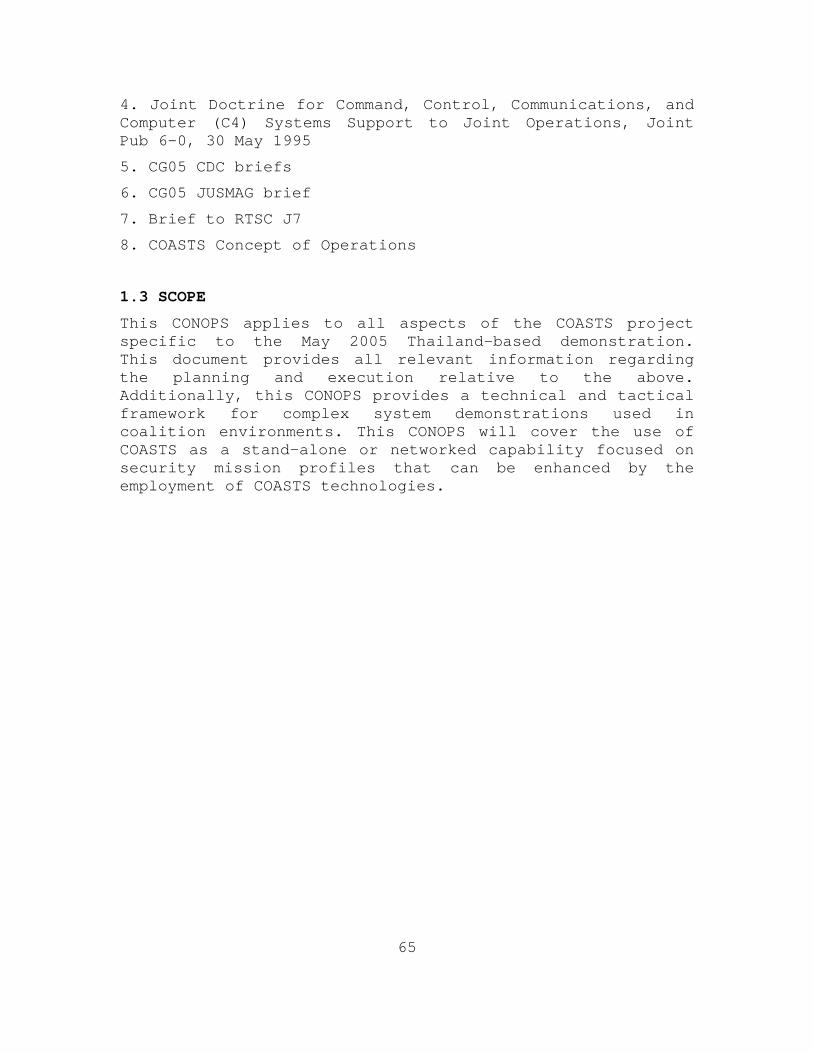
65
4. Joint Doctrine for Command, Control, Communications, and Computer (C4) Systems Support to Joint Operations, Joint Pub 6-0, 30 May 1995
5. CG05 CDC briefs
6. CG05 JUSMAG brief
7. Brief to RTSC J7
8. COASTS Concept of Operations
1.3 SCOPE
This CONOPS applies to all aspects of the COASTS project specific to the May 2005 Thailand-based demonstration. This document provides all relevant information regarding the planning and execution relative to the above. Additionally, this CONOPS provides a technical and tactical framework for complex system demonstrations used in coalition environments. This CONOPS will cover the use of COASTS as a stand-alone or networked capability focused on security mission profiles that can be enhanced by the employment of COASTS technologies.
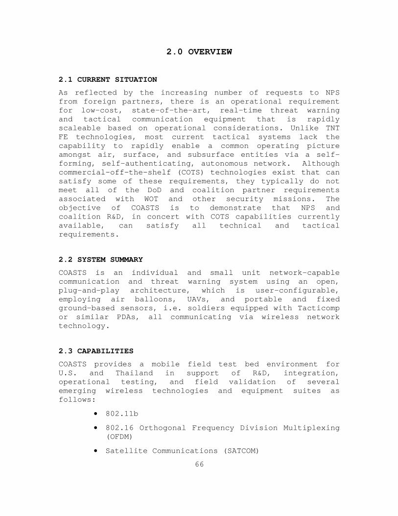
66
2.0 OVERVIEW
2.1 CURRENT SITUATION
As reflected by the increasing number of requests to NPS from foreign partners, there is an operational requirement for low-cost, state-of-the-art, real-time threat warning and tactical communication equipment that is rapidly scaleable based on operational considerations. Unlike TNT FE technologies, most current tactical systems lack the capability to rapidly enable a common operating picture amongst air, surface, and subsurface entities via a self-forming, self-authenticating, autonomous network. Although commercial-off-the-shelf (COTS) technologies exist that can satisfy some of these requirements, they typically do not meet all of the DoD and coalition partner requirements associated with WOT and other security missions. The objective of COASTS is to demonstrate that NPS and coalition R&D, in concert with COTS capabilities currently available, can satisfy all technical and tactical requirements.
2.2 SYSTEM SUMMARY
COASTS is an individual and small unit network-capable communication and threat warning system using an open, plug-and-play architecture, which is user-configurable, employing air balloons, UAVs, and portable and fixed ground-based sensors, i.e. soldiers equipped with Tacticomp or similar PDAs, all communicating via wireless network technology.
2.3 CAPABILITIES
COASTS provides a mobile field test bed environment for U.S. and Thailand in support of R&D, integration, operational testing, and field validation of several emerging wireless technologies and equipment suites as follows:
• 802.11b
• 802.16 Orthogonal Frequency Division Multiplexing (OFDM)
• Satellite Communications (SATCOM)
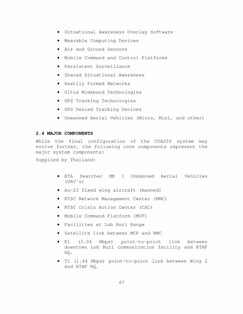
67
• Situational Awareness Overlay Software
• Wearable Computing Devices
• Air and Ground Sensors
• Mobile Command and Control Platforms
• Persistent Surveillance
• Shared Situational Awareness
• Hastily Formed Networks
• Ultra Wideband Technologies
• GPS Tracking Technologies
• GPS Denied Tracking Devices
• Unmanned Aerial Vehicles (Micro, Mini, and other)
2.4 MAJOR COMPONENTS
While the final configuration of the COASTS system may evolve further, the following core components represent the major system components:
Supplied by Thailand:
• RTA Searcher MK 1 Unmanned Aerial Vehicles (UAV’s)
• Au-23 fixed wing aircraft (manned)
• RTSC Network Management Center (NMC)
• RTSC Crisis Action Center (CAC)
• Mobile Command Platform (MCP)
• Facilities at Lob Buri Range
• Satellite link between MCP and NMC
• E1 (2.04 Mbps) point-to-point link between downtown Lob Buri communication facility and RTAF HQ.
• T1 (1.44 Mbps) point-to-point link between Wing 2 and RTAF HQ.
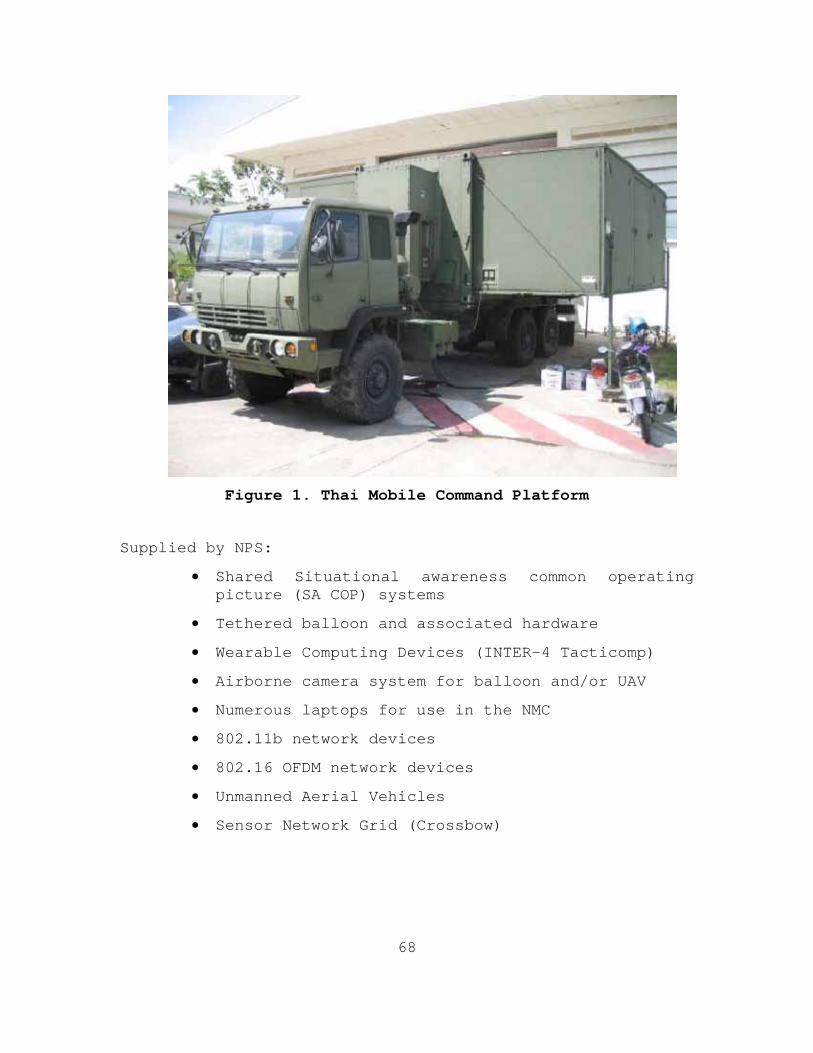
68
Figure 1. Thai Mobile Command Platform
Supplied by NPS:
• Shared Situational awareness common operating picture (SA COP) systems
• Tethered balloon and associated hardware
• Wearable Computing Devices (INTER-4 Tacticomp)
• Airborne camera system for balloon and/or UAV
• Numerous laptops for use in the NMC
• 802.11b network devices
• 802.16 OFDM network devices
• Unmanned Aerial Vehicles
• Sensor Network Grid (Crossbow)
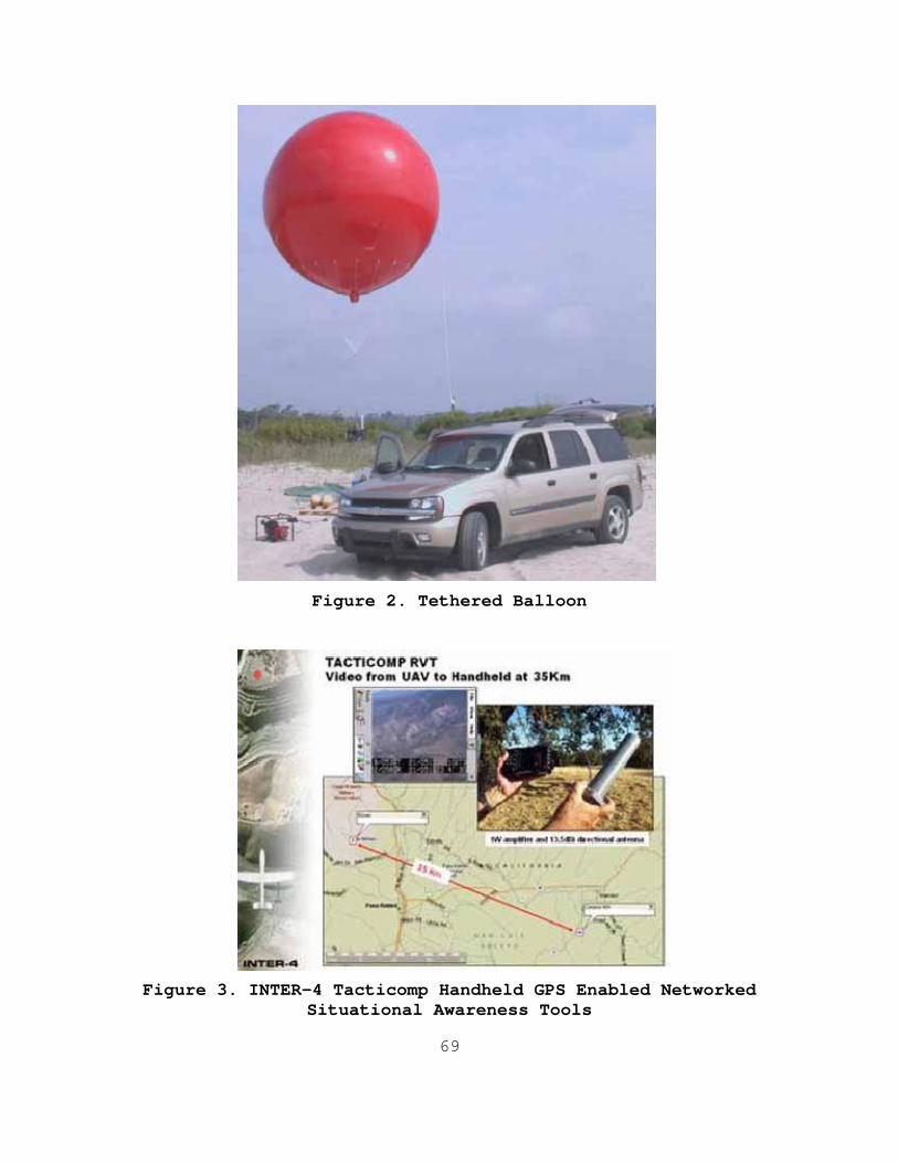
69
Figure 2. Tethered Balloon
Figure 3. INTER-4 Tacticomp Handheld GPS Enabled Networked Situational Awareness Tools

70
2.5 CONFIGURATIONS
The May 2005 COASTS demonstration will have three basic configurations: (1) as a command, control, collection, and communication suite; (2) a threat warning system; and (3) as an intelligence collection system.
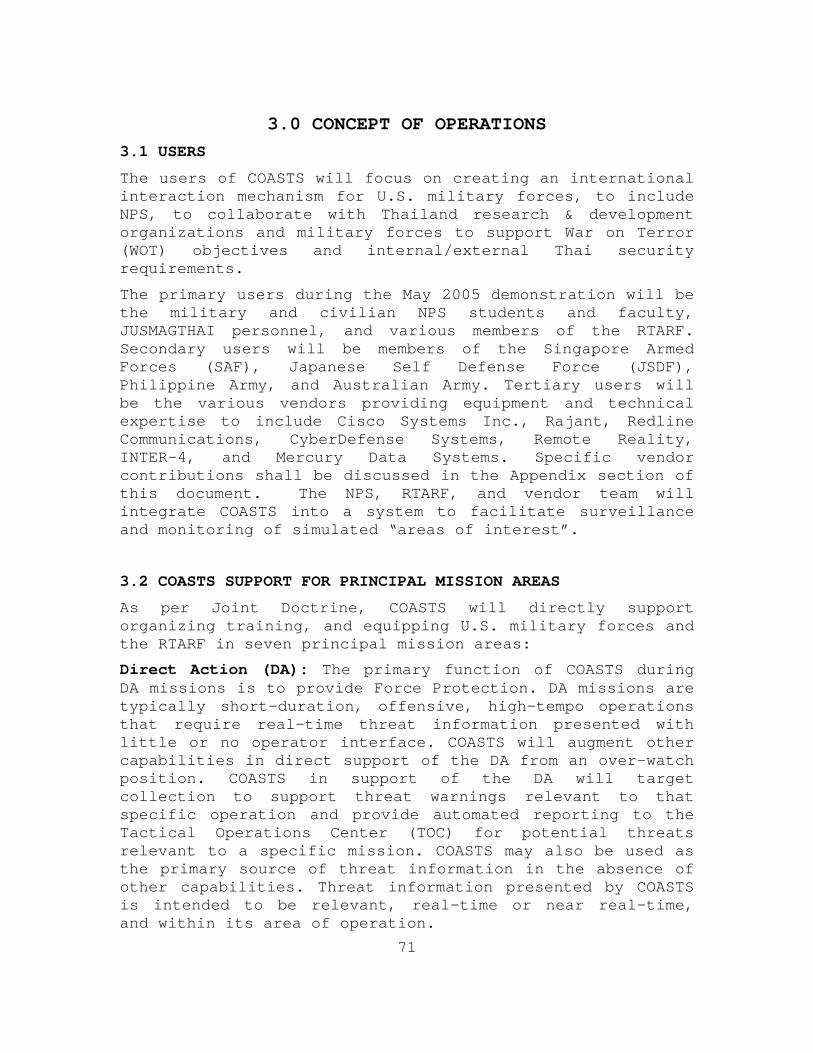
71
3.0 CONCEPT OF OPERATIONS
3.1 USERS
The users of COASTS will focus on creating an international interaction mechanism for U.S. military forces, to include NPS, to collaborate with Thailand research & development organizations and military forces to support War on Terror (WOT) objectives and internal/external Thai security requirements.
The primary users during the May 2005 demonstration will be the military and civilian NPS students and faculty, JUSMAGTHAI personnel, and various members of the RTARF. Secondary users will be members of the Singapore Armed Forces (SAF), Japanese Self Defense Force (JSDF), Philippine Army, and Australian Army. Tertiary users will be the various vendors providing equipment and technical expertise to include Cisco Systems Inc., Rajant, Redline Communications, CyberDefense Systems, Remote Reality, INTER-4, and Mercury Data Systems. Specific vendor contributions shall be discussed in the Appendix section of this document. The NPS, RTARF, and vendor team will integrate COASTS into a system to facilitate surveillance and monitoring of simulated “areas of interest”.
3.2 COASTS SUPPORT FOR PRINCIPAL MISSION AREAS
As per Joint Doctrine, COASTS will directly support organizing training, and equipping U.S. military forces and the RTARF in seven principal mission areas:
Direct Action (DA): The primary function of COASTS during DA missions is to provide Force Protection. DA missions are typically short-duration, offensive, high-tempo operations that require real-time threat information presented with little or no operator interface. COASTS will augment other capabilities in direct support of the DA from an over-watch position. COASTS in support of the DA will target collection to support threat warnings relevant to that specific operation and provide automated reporting to the Tactical Operations Center (TOC) for potential threats relevant to a specific mission. COASTS may also be used as the primary source of threat information in the absence of other capabilities. Threat information presented by COASTS is intended to be relevant, real-time or near real-time, and within its area of operation.
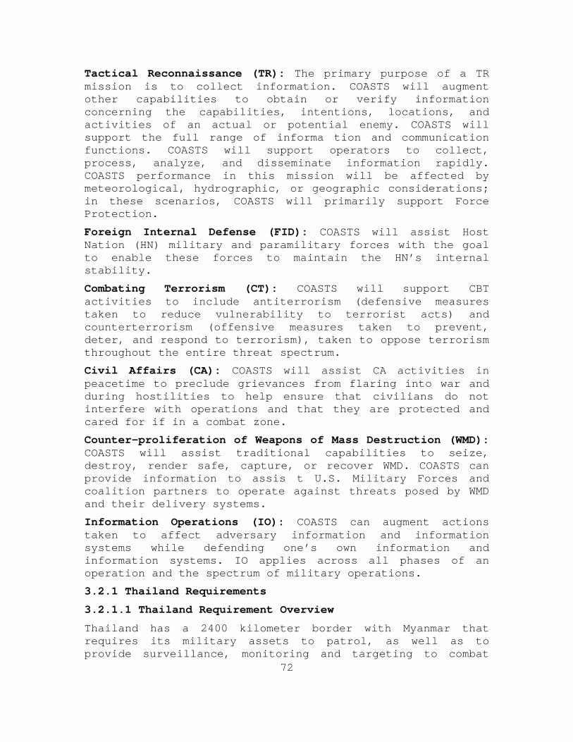
72
Tactical Reconnaissance (TR): The primary purpose of a TR mission is to collect information. COASTS will augment other capabilities to obtain or verify information concerning the capabilities, intentions, locations, and activities of an actual or potential enemy. COASTS will support the full range of informa tion and communication functions. COASTS will support operators to collect, process, analyze, and disseminate information rapidly. COASTS performance in this mission will be affected by meteorological, hydrographic, or geographic considerations; in these scenarios, COASTS will primarily support Force Protection.
Foreign Internal Defense (FID): COASTS will assist Host Nation (HN) military and paramilitary forces with the goal to enable these forces to maintain the HN’s internal stability.
Combating Terrorism (CT): COASTS will support CBT activities to include antiterrorism (defensive measures taken to reduce vulnerability to terrorist acts) and counterterrorism (offensive measures taken to prevent, deter, and respond to terrorism), taken to oppose terrorism throughout the entire threat spectrum.
Civil Affairs (CA): COASTS will assist CA activities in peacetime to preclude grievances from flaring into war and during hostilities to help ensure that civilians do not interfere with operations and that they are protected and cared for if in a combat zone.
Counter-proliferation of Weapons of Mass Destruction (WMD): COASTS will assist traditional capabilities to seize, destroy, render safe, capture, or recover WMD. COASTS can provide information to assis t U.S. Military Forces and coalition partners to operate against threats posed by WMD and their delivery systems.
Information Operations (IO): COASTS can augment actions taken to affect adversary information and information systems while defending one’s own information and information systems. IO applies across all phases of an operation and the spectrum of military operations.
3.2.1 Thailand Requirements
3.2.1.1 Thailand Requirement Overview
Thailand has a 2400 kilometer border with Myanmar that requires its military assets to patrol, as well as to provide surveillance, monitoring and targeting to combat
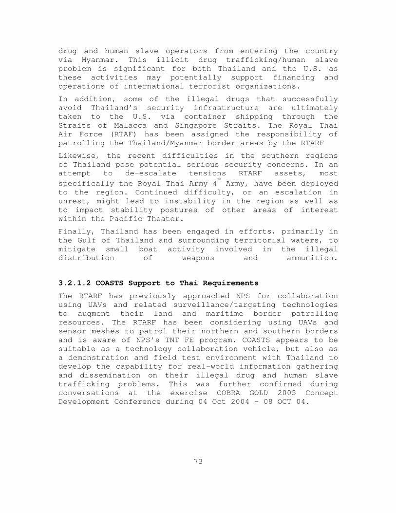
73
drug and human slave operators from entering the country via Myanmar. This illicit drug trafficking/human slave problem is significant for both Thailand and the U.S. as these activities may potentially support financing and operations of international terrorist organizations.
In addition, some of the illegal drugs that successfully avoid Thailand’s security infrastructure are ultimately taken to the U.S. via container shipping through the Straits of Malacca and Singapore Straits. The Royal Thai Air Force (RTAF) has been assigned the responsibility of patrolling the Thailand/Myanmar border areas by the RTARF
Likewise, the recent difficulties in the southern regions of Thailand pose potential serious security concerns. In an attempt to de-escalate tensions RTARF assets, most specifically the Royal Thai Army 4
th
Army, have been deployed to the region. Continued difficulty, or an escalation in unrest, might lead to instability in the region as well as to impact stability postures of other areas of interest within the Pacific Theater.
Finally, Thailand has been engaged in efforts, primarily in the Gulf of Thailand and surrounding territorial waters, to mitigate small boat activity involved in the illegal distribution of weapons and ammunition.
3.2.1.2 COASTS Support to Thai Requirements
The RTARF has previously approached NPS for collaboration using UAVs and related surveillance/targeting technologies to augment their land and maritime border patrolling resources. The RTARF has been considering using UAVs and sensor meshes to patrol their northern and southern borders and is aware of NPS’s TNT FE program. COASTS appears to be suitable as a technology collaboration vehicle, but also as a demonstration and field test environment with Thailand to develop the capability for real-world information gathering and dissemination on their illegal drug and human slave trafficking problems. This was further confirmed during conversations at the exercise COBRA GOLD 2005 Concept Development Conference during 04 Oct 2004 – 08 OCT 04.
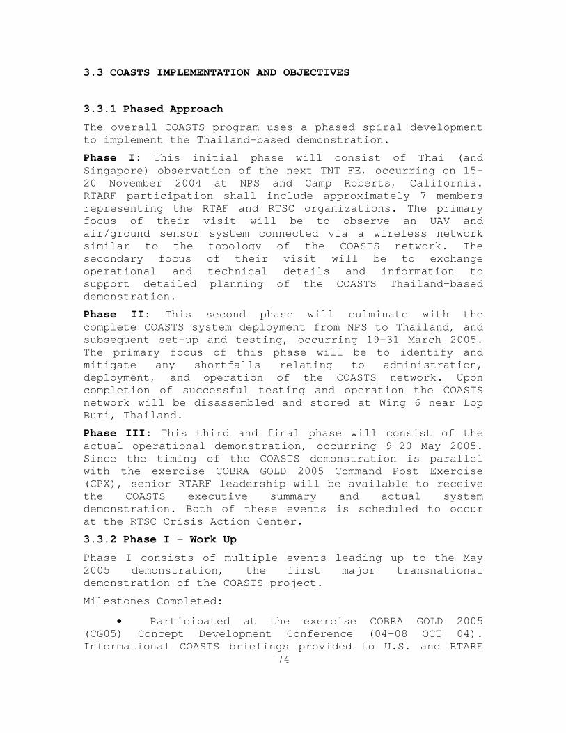
74
3.3 COASTS IMPLEMENTATION AND OBJECTIVES
3.3.1 Phased Approach
The overall COASTS program uses a phased spiral development to implement the Thailand-based demonstration.
Phase I: This initial phase will consist of Thai (and Singapore) observation of the next TNT FE, occurring on 15-20 November 2004 at NPS and Camp Roberts, California. RTARF participation shall include approximately 7 members representing the RTAF and RTSC organizations. The primary focus of their visit will be to observe an UAV and air/ground sensor system connected via a wireless network similar to the topology of the COASTS network. The secondary focus of their visit will be to exchange operational and technical details and information to support detailed planning of the COASTS Thailand-based demonstration.
Phase II: This second phase will culminate with the complete COASTS system deployment from NPS to Thailand, and subsequent set-up and testing, occurring 19-31 March 2005. The primary focus of this phase will be to identify and mitigate any shortfalls relating to administration, deployment, and operation of the COASTS network. Upon completion of successful testing and operation the COASTS network will be disassembled and stored at Wing 6 near Lop Buri, Thailand.
Phase III: This third and final phase will consist of the actual operational demonstration, occurring 9-20 May 2005. Since the timing of the COASTS demonstration is parallel with the exercise COBRA GOLD 2005 Command Post Exercise (CPX), senior RTARF leadership will be available to receive the COASTS executive summary and actual system demonstration. Both of these events is scheduled to occur at the RTSC Crisis Action Center.
3.3.2 Phase I - Work Up
Phase I consists of multiple events leading up to the May 2005 demonstration, the first major transnational demonstration of the COASTS project.
Milestones Completed:
• Participated at the exercise COBRA GOLD 2005 (CG05) Concept Development Conference (04-08 OCT 04). Informational COASTS briefings provided to U.S. and RTARF
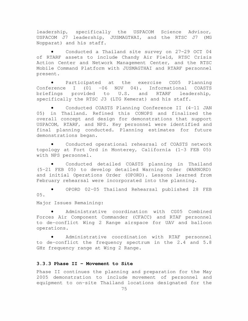
75
leadership, specifically the USPACOM Science Advisor, USPACOM J7 leadership, JUSMAGTHAI, and the RTSC J7 (MG Nopparat) and his staff.
• Conducted a Thailand site survey on 27-29 OCT 04 of RTARF assets to include Chandy Air Field, RTSC Crisis Action Center and Network Management Center, and the RTSC Mobile Command Platform with JUSMAGTHAI and RTARF personnel present.
• Participated at the exercise CG05 Planning Conference I (01 -06 NOV 04). Informational COASTS briefings provided to U.S. and RTARF leadership, specifically the RTSC J3 (LTG Kemerat) and his staff.
• Conducted COASTS Planning Conference II (4-11 JAN 05) in Thailand. Refined this CONOPS and finalized the overall concept and design for demonstrations that support USPACOM, RTARF, and NPS. Key personnel were identified and final planning conducted. Planning estimates for future demonstrations began.
• Conducted operational rehearsal of COASTS network topology at Fort Ord in Monterey, California (1-3 FEB 05) with NPS personnel.
• Conducted detailed COASTS planning in Thailand (5-21 FEB 05) to develop detailed Warning Order (WARNORD) and initial Operations Order (OPORD). Lessons learned from February rehearsal were incorporated into the planning.
• OPORD 02-05 Thailand Rehearsal published 28 FEB 05.
Major Issues Remaining:
• Administrative coordination with CG05 Combined Forces Air Component Commander (CFACC) and RTAF personnel to de-conflict Wing 2 Range airspace for UAV and balloon operations.
• Administrative coordination with RTAF personnel to de-conflict the frequency spectrum in the 2.4 and 5.8 GHz frequency range at Wing 2 Range.
3.3.3 Phase II – Movement to Site
Phase II continues the planning and preparation for the May 2005 demonstration to include movement of personnel and equipment to on-site Thailand locations designated for the
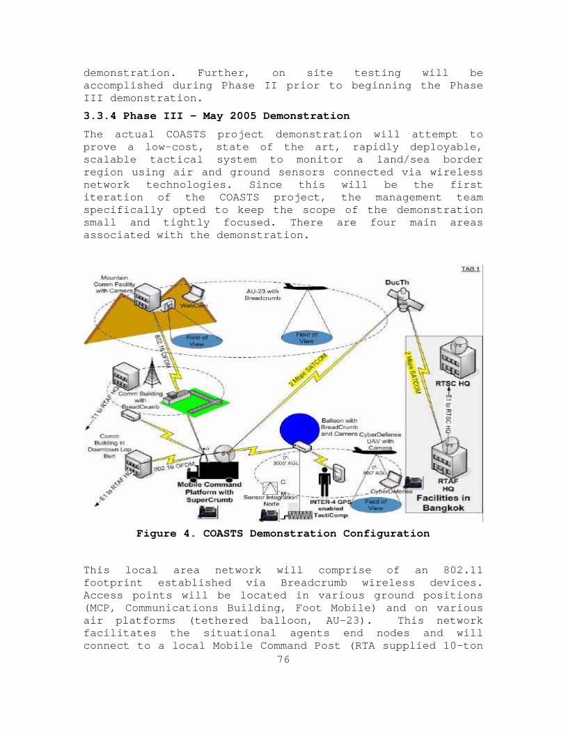
76
demonstration. Further, on site testing will be accomplished during Phase II prior to beginning the Phase III demonstration.
3.3.4 Phase III – May 2005 Demonstration
The actual COASTS project demonstration will attempt to prove a low-cost, state of the art, rapidly deployable, scalable tactical system to monitor a land/sea border region using air and ground sensors connected via wireless network technologies. Since this will be the first iteration of the COASTS project, the management team specifically opted to keep the scope of the demonstration small and tightly focused. There are four main areas associated with the demonstration.
Figure 4. COASTS Demonstration Configuration
This local area network will comprise of an 802.11 footprint established via Breadcrumb wireless devices. Access points will be located in various ground positions (MCP, Communications Building, Foot Mobile) and on various air platforms (tethered balloon, AU-23). This network facilitates the situational agents end nodes and will connect to a local Mobile Command Post (RTA supplied 10-ton
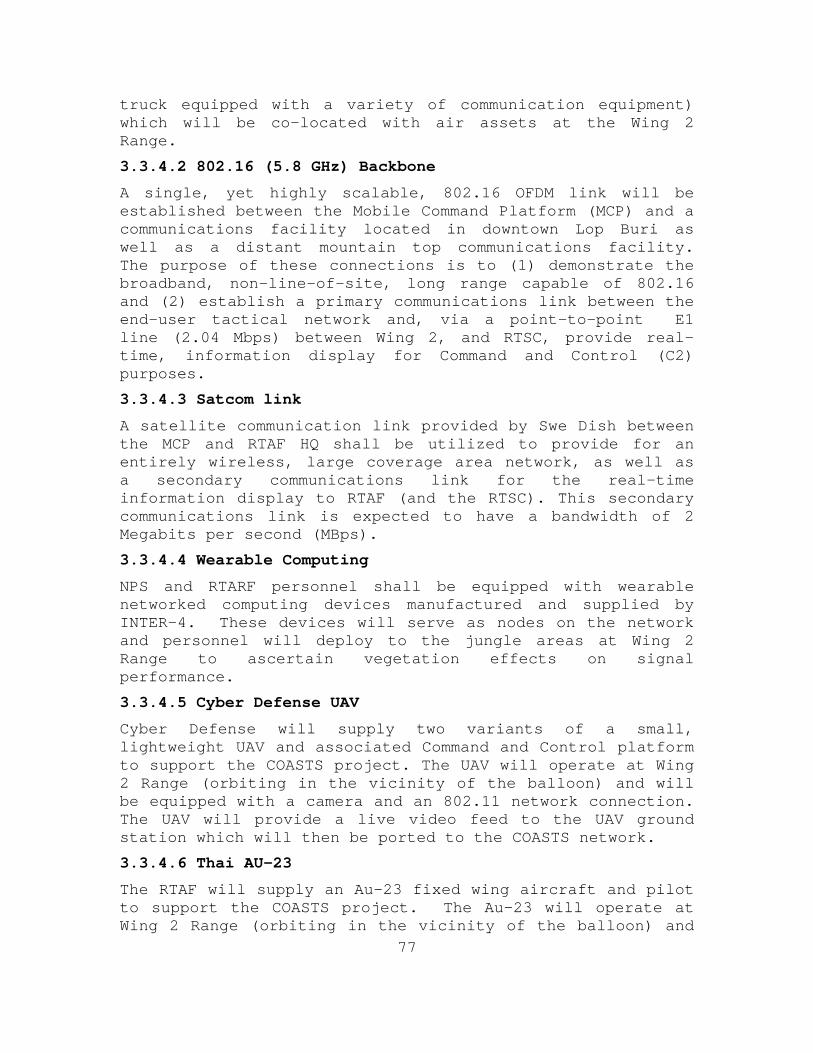
77
truck equipped with a variety of communication equipment) which will be co-located with air assets at the Wing 2 Range.
3.3.4.2 802.16 (5.8 GHz) Backbone
A single, yet highly scalable, 802.16 OFDM link will be established between the Mobile Command Platform (MCP) and a communications facility located in downtown Lop Buri as well as a distant mountain top communications facility. The purpose of these connections is to (1) demonstrate the broadband, non-line-of-site, long range capable of 802.16 and (2) establish a primary communications link between the end-user tactical network and, via a point-to-point E1 line (2.04 Mbps) between Wing 2, and RTSC, provide real-time, information display for Command and Control (C2) purposes.
3.3.4.3 Satcom link
A satellite communication link provided by Swe Dish between the MCP and RTAF HQ shall be utilized to provide for an entirely wireless, large coverage area network, as well as a secondary communications link for the real-time information display to RTAF (and the RTSC). This secondary communications link is expected to have a bandwidth of 2 Megabits per second (MBps).
3.3.4.4 Wearable Computing
NPS and RTARF personnel shall be equipped with wearable networked computing devices manufactured and supplied by INTER-4. These devices will serve as nodes on the network and personnel will deploy to the jungle areas at Wing 2 Range to ascertain vegetation effects on signal performance.
3.3.4.5 Cyber Defense UAV
Cyber Defense will supply two variants of a small, lightweight UAV and associated Command and Control platform to support the COASTS project. The UAV will operate at Wing 2 Range (orbiting in the vicinity of the balloon) and will be equipped with a camera and an 802.11 network connection. The UAV will provide a live video feed to the UAV ground station which will then be ported to the COASTS network.
3.3.4.6 Thai AU-23
The RTAF will supply an Au-23 fixed wing aircraft and pilot to support the COASTS project. The Au-23 will operate at Wing 2 Range (orbiting in the vicinity of the balloon) and
78
will be equipped with different payloads consisting of various video and wireless networking. The Au-23 will provide an opportunity to test the different payloads under different conditions and altitudes and also to serve as a back-up aerial node in the COASTS network topology.
3.3.4.7 Shared Situational Awareness (SSA) Agents
These are the nodes and software associated with unmanned sensors such as seismic monitors, sound sensors, and streaming ground or balloon originating video feeds some with GPS enabled systems. The SA Agent will be displayed onboard the MCP, the RTAF, and the RTSC Crisis Action Center (CAC).
3.3.4.8 Tactical Operations Center / Network Operations Center (NOC)
The Tactical Operations Center (TOC) and Network Operations Center (NOC) collect and display the data feeds from the various nodes across the network. This is the center of the Command and Control capabilities of the COASTS program and where the deployed technology fuses and the force multiplying effects of the technology is leveraged. The MCP shall function as a TOC. In addition, the RTAF Air Operations Center and the Air Force Operations Center (both of which are co-located at RTAF HQ in Bangkok) will function as a NOC.
3.3.5 Future Items and Other Capabilities
3.3.5.1 Network Defense
A survey of the network from a defensive point of view using open source, and COTS products may be conducted on a not-to-interfere basis.
3.3.5.2 Modeling and Simulation
Using modeling and simulation techniques, results from the demonstration may be compared to predicted results in order to enhance our modeling capabilities and reducing the need to establish a network for testing.
An additional set of relatively simple tests, modeled after an experiment proposed for the NPS TNT Field Experiment 05-1, could be conducted as “littorals operations” setting up a point-to-point 802.16 access point enabled WLAN on the coast in Thailand with a ship positioned to access the
79
network. A Test Plan could be developed with the ship moving further and further away from the access point while collecting network performance data (throughput measuring performance with different types of data such as voice, video, data – all at varying distances). This experiment could also focus on meteorological information as it effects network performance (throughput and sensor performance), as the much higher levels of moisture in the Gulf of Thailand will significantly impact performance of networks and sensors.
3.3.5.3 Micro/Mini UAVs
Both the RTA and U.S. military forces are interested in tactical application of UAVs, specifically with respect to the implementation and operationalizing of micro and mini-UAVs. These extremely small form factor UAVs, using swarming technologies or other process, can augment and/or potentially replace the larger, point target of larger, traditional UAVs.
3.3.5.4 High-Altitude Balloons
Again, both the RTA and U.S. military forces are pursuing the application of high-altitude, steerable, non-tethered airships. The Thai Department of Research and Development Office (DRDO) has already begun experimentation in this technology area and is seeking to partner with NPS to provide better, more capable, solutions.
3.3.5.5 Maritime Missions
The Thai DRDO has previously conducted ship-to-shore wireless network experiments in the Gulf of Thailand and is seeking to link information collected from seaborne sensors with a surface search radar system deployed to the Royal Thai Navy Base at Sattihip. Ultimately this information will be fused and passed to the newly created Maritime Operations Facility for Intelligence Collection (MOFIC).
In 2006, COASTS operation will be conducted in Sattahip area, RTN will be the host for this area. COASTS will be conducted both ground and maritime, to simulate as the southern Thailand. RTN will support the U-taphao airfield for AU-23A, and UAV searcher, also the transportation within the area. In the case that COASTS will operate in the sea, RTN will provide the ships upon the requested.
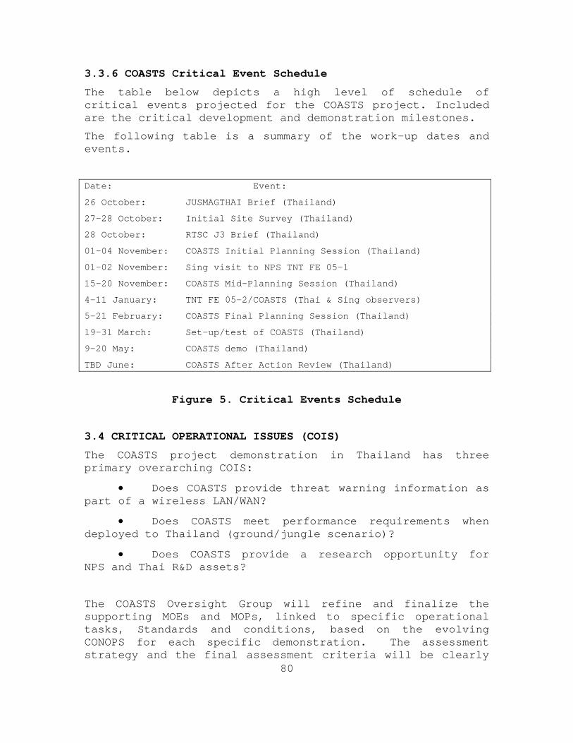
80
3.3.6 COASTS Critical Event Schedule
The table below depicts a high level of schedule of critical events projected for the COASTS project. Included are the critical development and demonstration milestones.
The following table is a summary of the work-up dates and events.
Date: Event:
26 October: JUSMAGTHAI Brief (Thailand)
27-28 October: Initial Site Survey (Thailand)
28 October: RTSC J3 Brief (Thailand)
01-04 November: COASTS Initial Planning Session (Thailand)
01-02 November: Sing visit to NPS TNT FE 05-1
15-20 November: COASTS Mid-Planning Session (Thailand)
4-11 January: TNT FE 05-2/COASTS (Thai & Sing observers)
5-21 February: COASTS Final Planning Session (Thailand)
19-31 March: Set-up/test of COASTS (Thailand)
9-20 May: COASTS demo (Thailand)
TBD June: COASTS After Action Review (Thailand)
Figure 5. Critical Events Schedule
3.4 CRITICAL OPERATIONAL ISSUES (COIS)
The COASTS project demonstration in Thailand has three primary overarching COIS:
• Does COASTS provide threat warning information as part of a wireless LAN/WAN?
• Does COASTS meet performance requirements when deployed to Thailand (ground/jungle scenario)?
• Does COASTS provide a research opportunity for NPS and Thai R&D assets?
The COASTS Oversight Group will refine and finalize the supporting MOEs and MOPs, linked to specific operational tasks, Standards and conditions, based on the evolving CONOPS for each specific demonstration. The assessment strategy and the final assessment criteria will be clearly
81
delineated in the appendix of the final demonstration CONOPS.
3.5 MEASURES OF EFFECTIVENESS (MOE) AND MEASURES OF PERFORMANCE (MOP)
The MOEs and MOPs for the COASTs demons tration in Thailand are as follows:
• Establish plan of action that may act as a guideline for future refinements and develop a dialogue for further participation.
Specifically:
• Establish Points of Contact within the Thai military and Research & Development community.
• Establish effective communication flow with Thai counterparts in regards to:
o Administration infrastructure (procedures)
o Training
o Planning
o Logistics
• Establish operationally feasible plan of action for the May 2005 demonstration.
• Aerial Access Point:
o UAV
o balloon
NOC/TOC: This Concept of Operation will act as a framework to add on specific experimental MOEs, MOPs, and other details in the appendix.
82
4.0 MANAGEMENT STRATEGY
4.1 PARTICIPATING ORGANIZATIONS, ROLES, AND RESPONSIBILITIES
4.1.1 COASTS Oversight Group
Chair: NPS Dean of Research
Members: NPS Principal Investigators (PIs) consisting of the Thailand and Singapore PIs, NPS Operational Manager, and NPS Technical Manager
4.1.2 NPS Principal Investigator (PI)
Lead element of the COASTS project; responsible for project oversight, coordination between NPS, DOD, foreign partners, and commercial vendors; responsible for all fiduciary reports and contractual agreements.
PI Thailand: Mr. James Ehlert
PI Singapore: Mr. Brian Steckler
4.1.3 NPS Operational Manager (OM)
The OM is responsible for developing all demonstrations, plans, collection and dissemination of data, site surveys, Measures of Effectiveness (MOE), Measures of Performance (MOP), NPS resource allocation, internal NPS coordination, and support to the PI.
The OM plans, coordinates and directs all user activities related to the COASTS project. The OM will develop and provide the CONOPS, TTPs, operational mission scenarios, and the overall utility assessment. Additionally, the OM will coordinate administrative tasks for user participants, equipment and facilities supporting demonstration events.
OM: Captain David Cooper, USMC
4.1.4 NPS Technical Manager (TM)
The TM is responsible for technical management including program management, engineering, and acquisition of technologies to integrate and demonstrate. The TM will
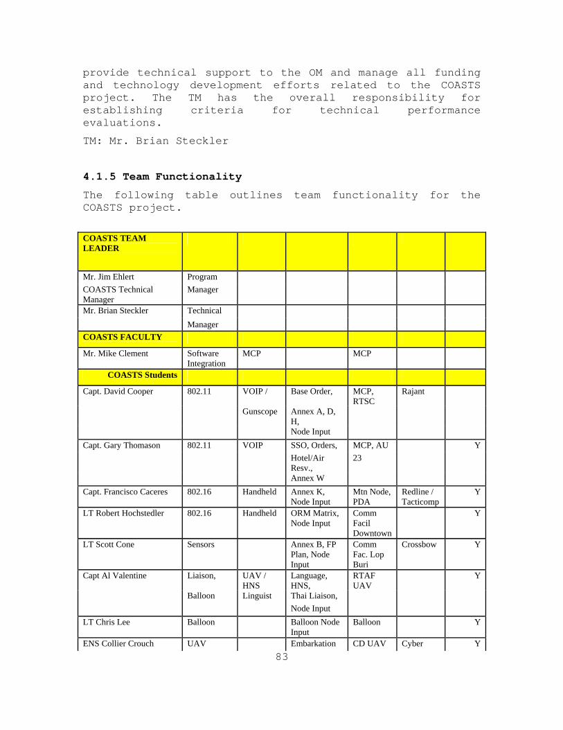
83
provide technical support to the OM and manage all funding and technology development efforts related to the COASTS project. The TM has the overall responsibility for establishing criteria for technical performance evaluations.
TM: Mr. Brian Steckler
4.1.5 Team Functionality
The following table outlines team functionality for the COASTS project.
COASTS TEAM LEADER
Mr. Jim Ehlert Program COASTS Technical Manager
Manager
Mr. Brian Steckler Technical Manager COASTS FACULTY Mr. Mike Clement Software
Integration MCP MCP
COASTS Students Capt. David Cooper 802.11 VOIP / Base Order, MCP,
RTSC Rajant
Gunscope Annex A, D, H,
Node Input Capt. Gary Thomason 802.11 VOIP SSO, Orders, MCP, AU Y
Hotel/Air Resv.,
23
Annex W Capt. Francisco Caceres 802.16 Handheld Annex K,
Node Input Mtn Node, PDA
Redline / Tacticomp
Y
LT Robert Hochstedler 802.16 Handheld ORM Matrix, Node Input
Comm Facil Downtown
Y
LT Scott Cone Sensors Annex B, FP Plan, Node Input
Comm Fac. Lop Buri
Crossbow Y
Capt Al Valentine Liaison, UAV / HNS
Language, HNS,
RTAF UAV
Y
Balloon Linguist Thai Liaison, Node Input LT Chris Lee Balloon Balloon Node
Input Balloon Y
ENS Collier Crouch UAV Embarkation CD UAV Cyber Y
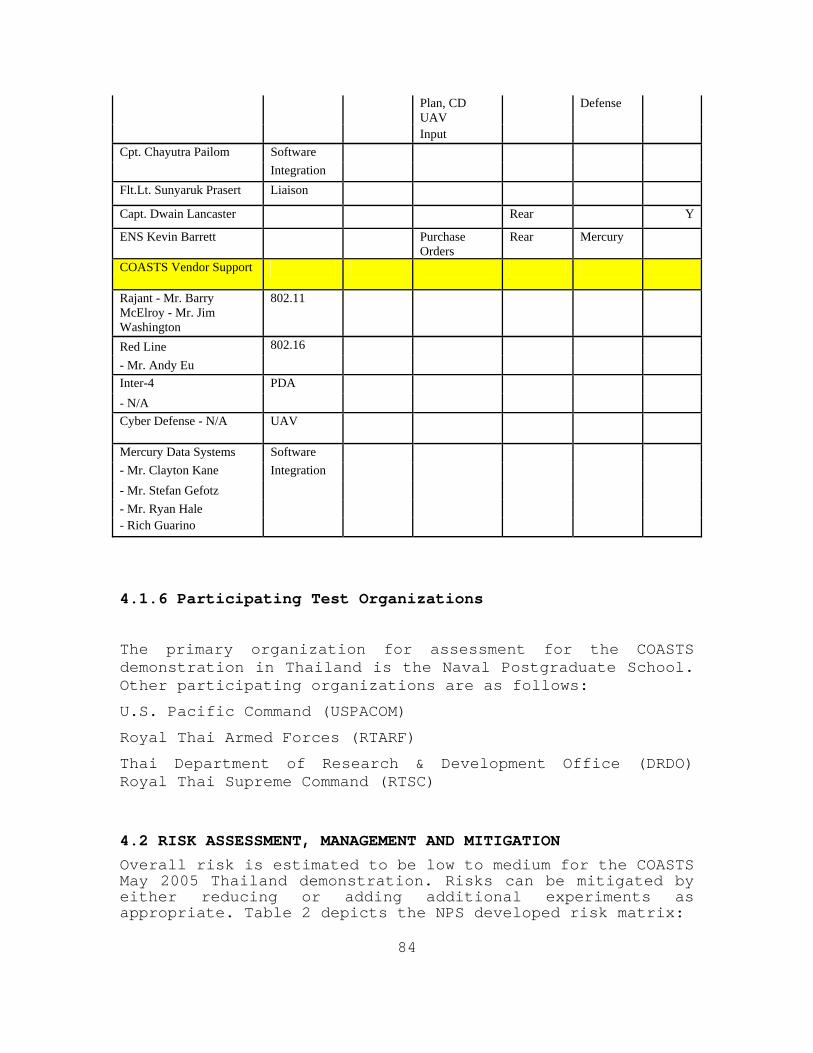
84
Plan, CD UAV
Defense
Input Cpt. Chayutra Pailom Software Integration Flt.Lt. Sunyaruk Prasert Liaison Capt. Dwain Lancaster Rear Y
ENS Kevin Barrett Purchase Orders
Rear Mercury
COASTS Vendor Support
Rajant - Mr. Barry McElroy - Mr. Jim Washington
802.11
Red Line 802.16 - Mr. Andy Eu Inter-4 PDA - N/A Cyber Defense - N/A UAV
Mercury Data Systems Software - Mr. Clayton Kane Integration - Mr. Stefan Gefotz - Mr. Ryan Hale - Rich Guarino
4.1.6 Participating Test Organizations
The primary organization for assessment for the COASTS demonstration in Thailand is the Naval Postgraduate School. Other participating organizations are as follows:
U.S. Pacific Command (USPACOM)
Royal Thai Armed Forces (RTARF)
Thai Department of Research & Development Office (DRDO) Royal Thai Supreme Command (RTSC)
4.2 RISK ASSESSMENT, MANAGEMENT AND MITIGATION
Overall risk is estimated to be low to medium for the COASTS May 2005 Thailand demonstration. Risks can be mitigated by either reducing or adding additional experiments as appropriate. Table 2 depicts the NPS developed risk matrix:
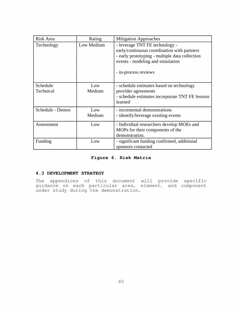
85
Risk Area Rating Mitigation Approaches Technology Low Medium - leverage TNT FE technology -
early/continuous coordination with partners - early prototyping - multiple data collection
events - modeling and simulation
- in-process reviews
Schedule Low - schedule estimates based on technology Technical Medium provider agreements - schedule estimates incorporate TNT FE lessons learned
Schedule - Demos Low - incremental demonstrations Medium - identify/leverage existing events
Assessment Low - Individual researchers develop MOEs and MOPs for their components of the demonstration. Funding Low - significant funding confirmed, additional sponsors contacted
Figure 6. Risk Matrix
4.3 DEVELOPMENT STRATEGY
The appendices of this document will provide specific guidance on each particular area, element, and component under study during the demonstration.
86
5.0 TRAINING, LOGISTIC AND SAFETY
5.1 TRAINING
A primary goal of the COASTS project in Thailand is to execute operational demonstrations in conjunction with U.S. and coalition warfighters. Accordingly, appropriate training materials will be developed for each demonstration and operator training will be conducted prior to each demonstration. Training will be performed by a combination of contractor and government personnel. There are also significant hands-on educational opportunities for NPS students, and it is expected that multiple NPS masters theses will be generated by participating US and foreign NPS students.
5.2 LOGISTICS
Maintenance and logistics support will be conducted using a combination of contractor support and in-house NPS expertise and facilities. This includes the development and distribution of maintenance, training, and operating manuals, instructions, or materials. During the demonstrations, reliability, availability, and maintainability information will be collected for later analysis and review.
5.2.1 COASTS Set-Up and Demo
The RTAF will conduct daily logistical movements via air/ground means between Bangkok and the Wing 2 Range for the NPS team during the March and May 2005 set-up and demonstration time periods. Transportation will primarily be on RTAF supplied C130 and UH-1 aircraft or buses. The departure and return schedule are currently undetermined but will be based on operational and administrative requirements during each set-up or demonstration time period. An Air Tasking Order will be co-managed by the RTAF and NPS Air Marshals for all aviation lift and operational requirements. The Host Nation Support Liaison will be responsible for managing all ground transportation requirements.
5.2.2 COASTS Equipment Shipping and Storage
The NPS will provide JUSMAGTHAI with a list of equipment to be shipped in support of the March set-up and the May demonstration. RTSC J7 and the US Embassy will help
87
facilitate the arrival of the equipment in Thailand and getting the equipment through Thailand Customs without delay.
The equipment will be stored at Wing 2 Range in, as of yet, an unidentified RTAF facility. The minimum requirements for this facility will be controlled access (lock and key) to prevent the loss of equipment and air-conditioning to preserve the material condition of electronic devices.
5.3 SAFETY
There could be safety or potential environmental hazards associated with technologies being considered. As needed a safety analysis will be performed to identify potential safety hazards and risks and determine appropriate controls to preclude mishaps and reduce risks. The OM will coordinate all safety efforts associated with demonstrations.
88
6.0 MODIFICATIONS
This CONOP is intended to be a living document. It will be updated as required to reflect changes to the COASTS project as it pertains to the Thailand demonstration. Most modifications will be at the discretion of the COASTS Oversight Group who will approve any substantive alterations to include changes in objectives, funding, schedule, and scope. Any changes, which materially affect commitments made by Thailand, will be approved by the affected organizations.
For major events, separate Warning Orders (WARNORD) and Operations Orders (OPORD) will be published. Interested parties should refer to these documents for the most up to date and detailed information relating to a specific event.

89
7.0 POINTS OF CONTACT
7.1 NAVAL POSTGRADUATE SCHOOL
Mr. Brian Steckler,
NPS Information Sciences Department Faculty
Mr. James Ehlert,
NPS Cryptologic Research Chair
Captain David Cooper
Information Sciences Department Student
Captain Gary Thomason
Information Sciences Department Student
Mr. Mike Clement
Information Sciences Department Research Associate
7.2 JUSMAGTHAI
Major Marc Anderson
Asst. Chief of Policy and Plans
7.3 US PACIFIC COMMAND
Mr. Chris Vogt
Science Advisor (J006)
7.4 ROYAL THAI ARMED FORCES
Major General Noporat Yodvimol
RTARF J7
Wing Commander Thanan Prateeptong
Combat R&D, Directorate of Operations, RTAF HQ
Wing Commander Ayuth (Air Marshall) RTAF HQ
90
Flight Lieutenant Surapong Srivanich
Combat R&D, Directorate of Operations
RTAF HQ
Flight Lieutenant Ruth
Communications Officer RTAF HQ
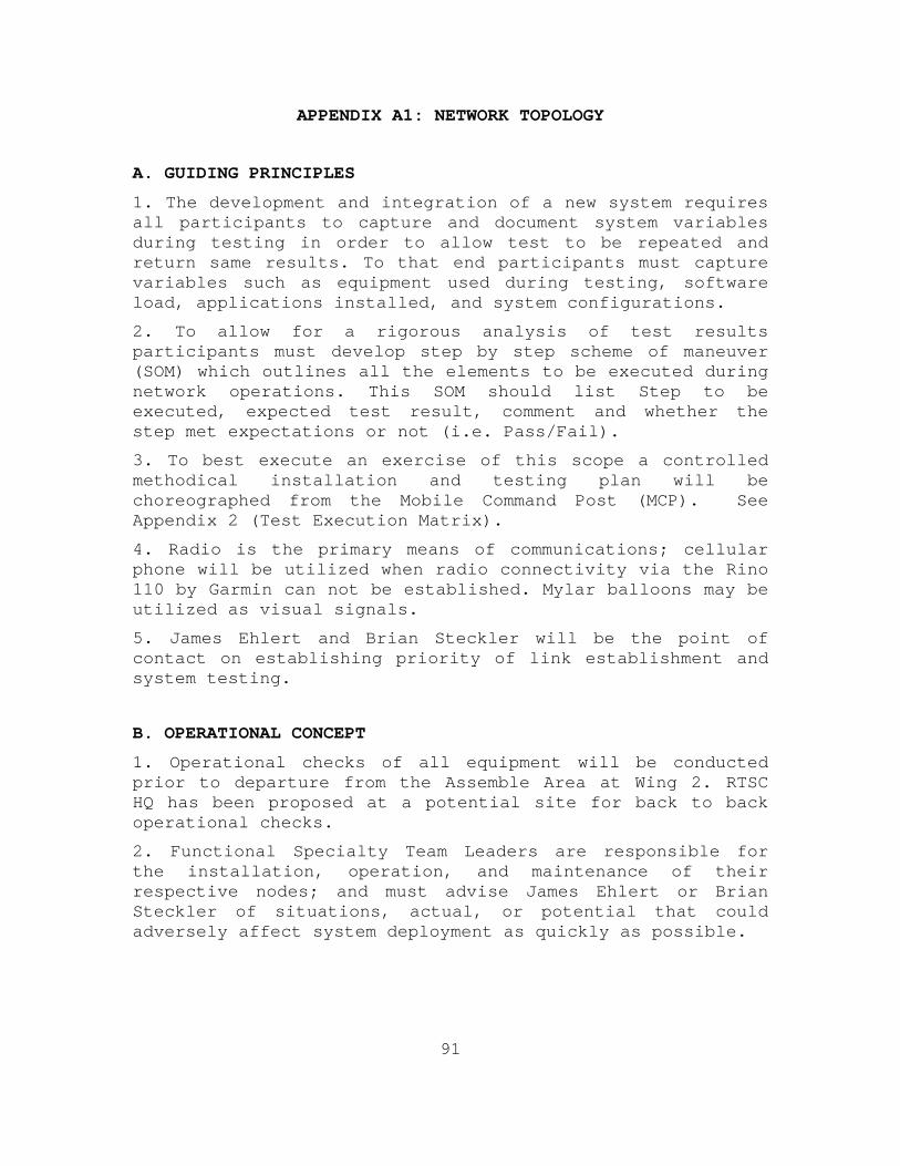
91
APPENDIX A1: NETWORK TOPOLOGY
A. GUIDING PRINCIPLES
1. The development and integration of a new system requires all participants to capture and document system variables during testing in order to allow test to be repeated and return same results. To that end participants must capture variables such as equipment used during testing, software load, applications installed, and system configurations.
2. To allow for a rigorous analysis of test results participants must develop step by step scheme of maneuver (SOM) which outlines all the elements to be executed during network operations. This SOM should list Step to be executed, expected test result, comment and whether the step met expectations or not (i.e. Pass/Fail).
3. To best execute an exercise of this scope a controlled methodical installation and testing plan will be choreographed from the Mobile Command Post (MCP). See Appendix 2 (Test Execution Matrix).
4. Radio is the primary means of communications; cellular phone will be utilized when radio connectivity via the Rino 110 by Garmin can not be established. Mylar balloons may be utilized as visual signals.
5. James Ehlert and Brian Steckler will be the point of contact on establishing priority of link establishment and system testing.
B. OPERATIONAL CONCEPT
1. Operational checks of all equipment will be conducted prior to departure from the Assemble Area at Wing 2. RTSC HQ has been proposed at a potential site for back to back operational checks.
2. Functional Specialty Team Leaders are responsible for the installation, operation, and maintenance of their respective nodes; and must advise James Ehlert or Brian Steckler of situations, actual, or potential that could adversely affect system deployment as quickly as possible.
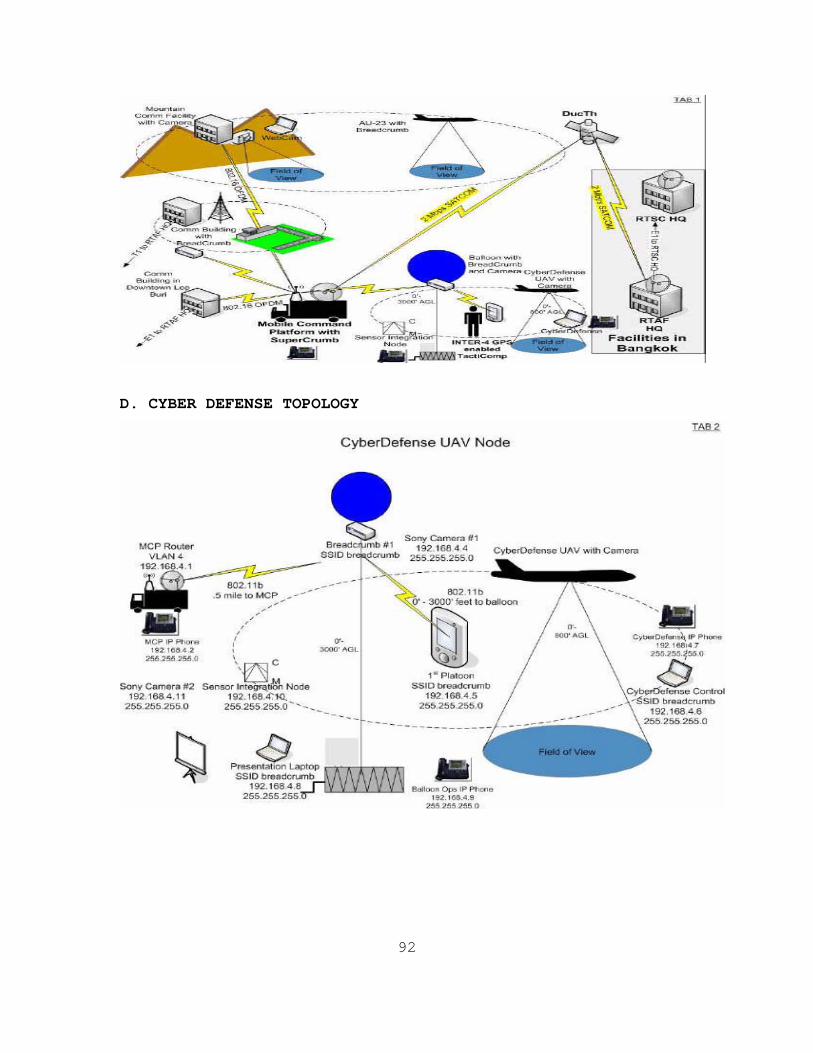
92
D. CYBER DEFENSE TOPOLOGY
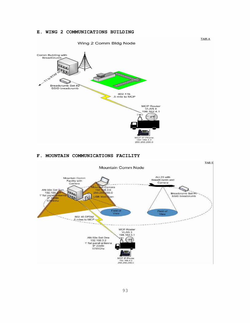
93
E. WING 2 COMMUNICATIONS BUILDING
F. MOUNTAIN COMMUNICATIONS FACILITY
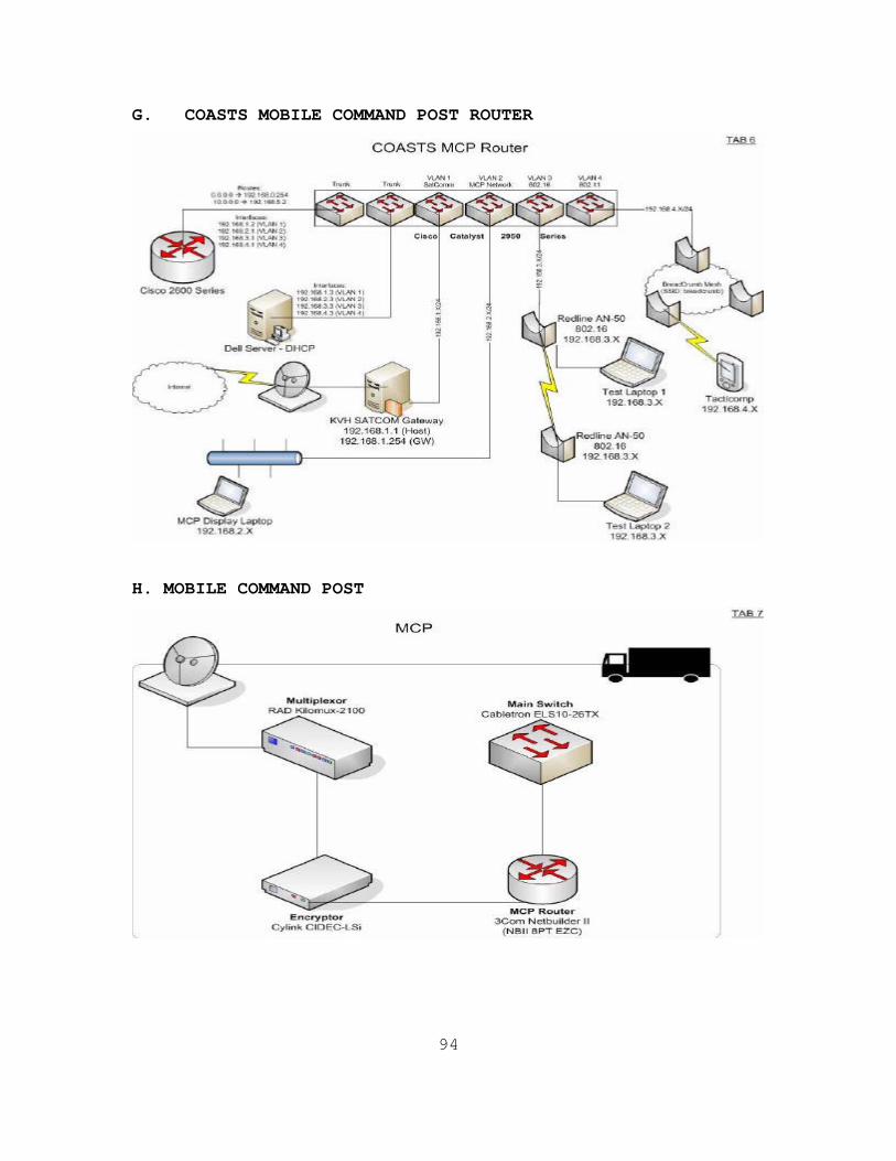
94
G. COASTS MOBILE COMMAND POST ROUTER
H. MOBILE COMMAND POST
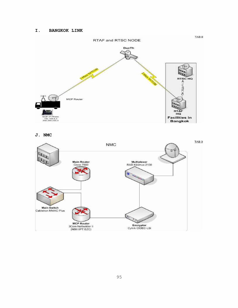
95
I. BANGKOK LINK
J. NMC
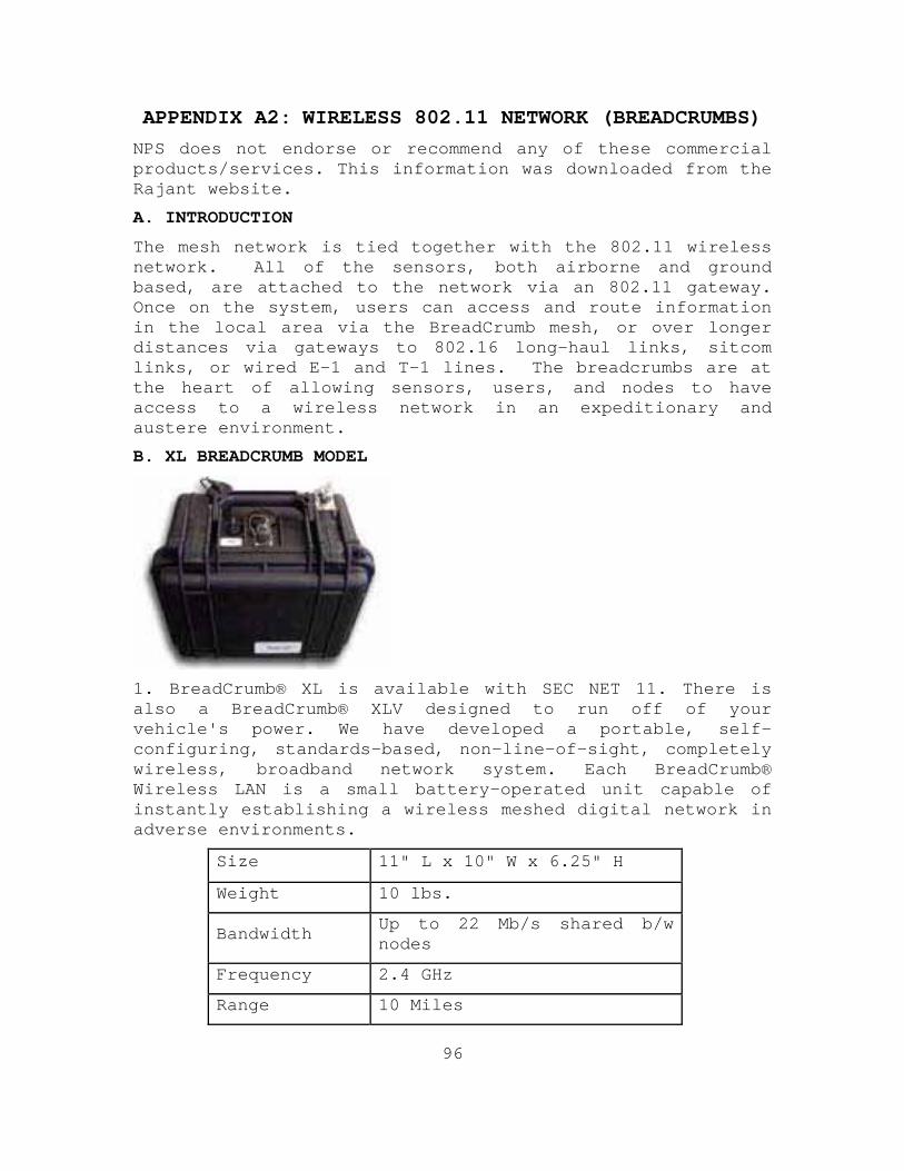
96
APPENDIX A2: WIRELESS 802.11 NETWORK (BREADCRUMBS)
NPS does not endorse or recommend any of these commercial products/services. This information was downloaded from the Rajant website.
A. INTRODUCTION
The mesh network is tied together with the 802.11 wireless network. All of the sensors, both airborne and ground based, are attached to the network via an 802.11 gateway. Once on the system, users can access and route information in the local area via the BreadCrumb mesh, or over longer distances via gateways to 802.16 long-haul links, sitcom links, or wired E-1 and T-1 lines. The breadcrumbs are at the heart of allowing sensors, users, and nodes to have access to a wireless network in an expeditionary and austere environment.
B. XL BREADCRUMB MODEL
1. BreadCrumb® XL is available with SEC NET 11. There is also a BreadCrumb® XLV designed to run off of your vehicle's power. We have developed a portable, self-configuring, standards-based, non-line-of-sight, completely wireless, broadband network system. Each BreadCrumb® Wireless LAN is a small battery-operated unit capable of instantly establishing a wireless meshed digital network in adverse environments.
Size 11" L x 10" W x 6.25" H
Weight 10 lbs.
Bandwidth Up to 22 Mb/s shared b/w nodes
Frequency 2.4 GHz
Range 10 Miles
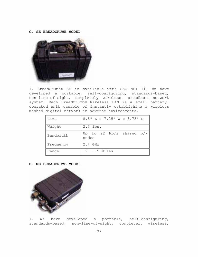
97
C. SE BREADCRUMB MODEL
1. BreadCrumb® SE is available with SEC NET 11. We have developed a portable, self-configuring, standards-based, non-line-of-sight, completely wireless, broadband network system. Each BreadCrumb® Wireless LAN is a small battery-operated unit capable of instantly establishing a wireless meshed digital network in adverse environments.
Size 8.5" L x 7.25" W x 3.75" D
Weight 2.3 lbs.
Bandwidth Up to 22 Mb/s shared b/w nodes
Frequency 2.4 GHz
Range .2 - .5 Miles
D. ME BREADCRUMB MODEL
1. We have developed a portable, self-configuring, standards-based, non-line-of-sight, completely wireless,
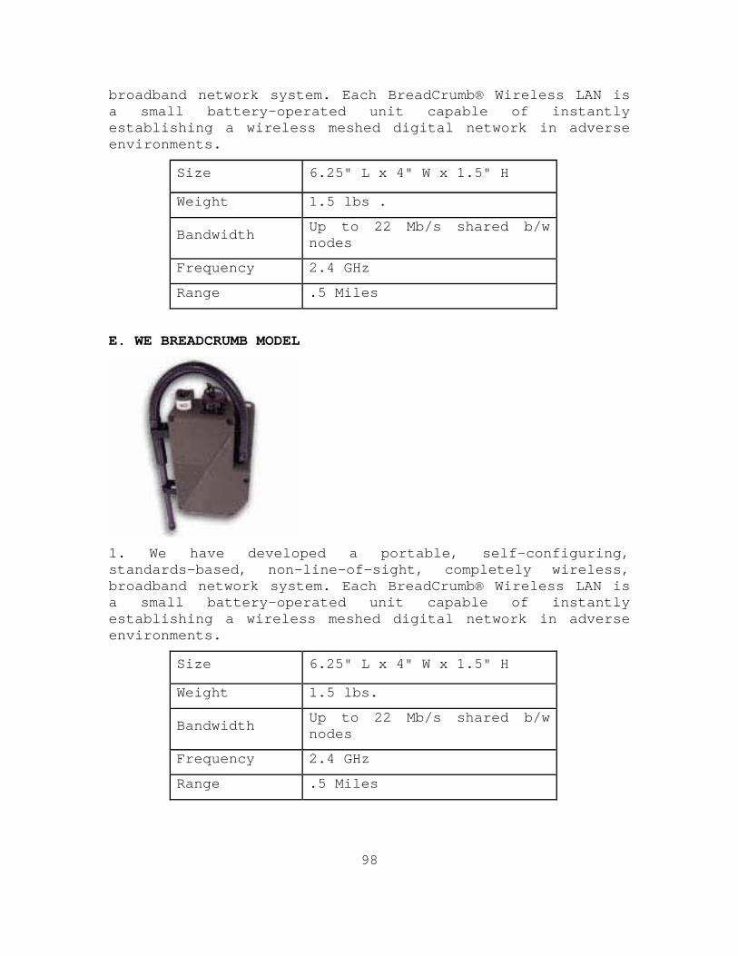
98
broadband network system. Each BreadCrumb® Wireless LAN is a small battery-operated unit capable of instantly establishing a wireless meshed digital network in adverse environments.
Size 6.25" L x 4" W x 1.5" H
Weight 1.5 lbs .
Bandwidth Up to 22 Mb/s shared b/w nodes
Frequency 2.4 GHz
Range .5 Miles
E. WE BREADCRUMB MODEL
1. We have developed a portable, self-configuring, standards-based, non-line-of-sight, completely wireless, broadband network system. Each BreadCrumb® Wireless LAN is a small battery-operated unit capable of instantly establishing a wireless meshed digital network in adverse environments.
Size 6.25" L x 4" W x 1.5" H
Weight 1.5 lbs.
Bandwidth Up to 22 Mb/s shared b/w nodes
Frequency 2.4 GHz
Range .5 Miles
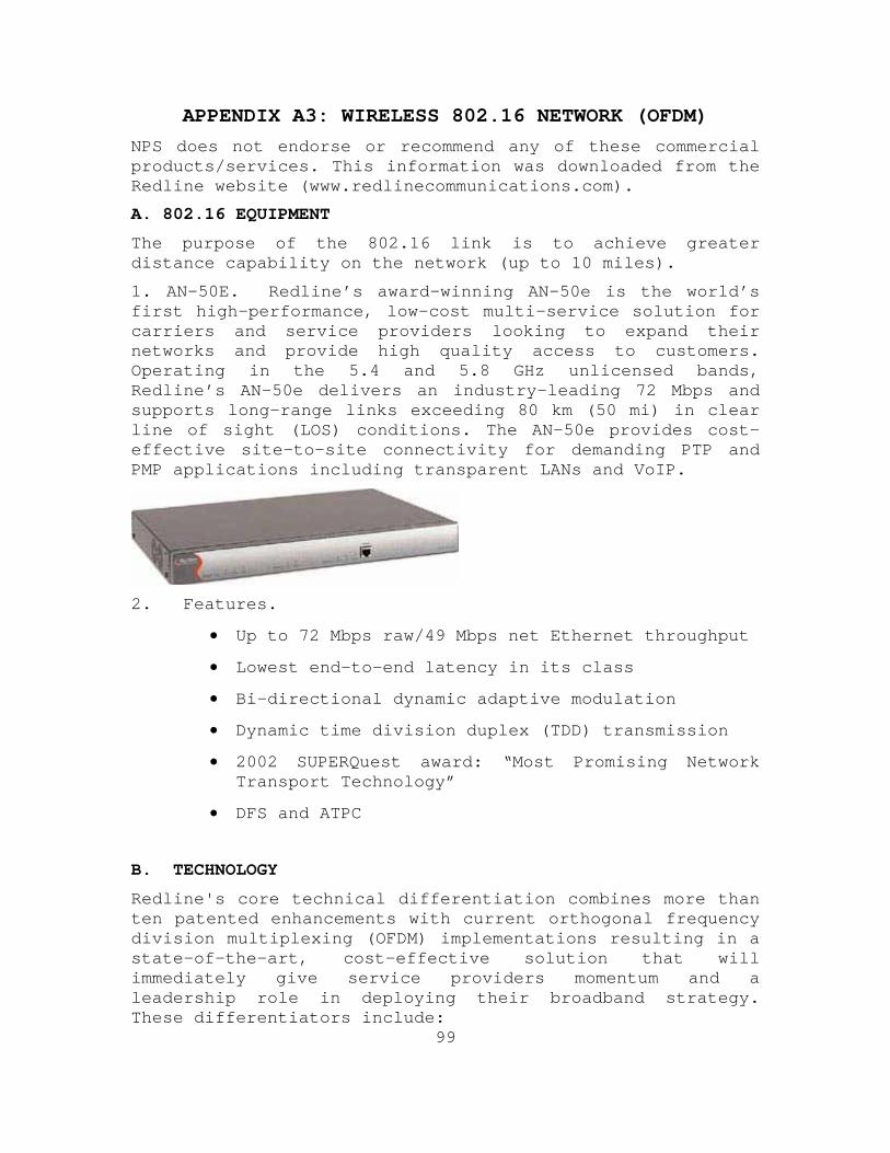
99
APPENDIX A3: WIRELESS 802.16 NETWORK (OFDM)
NPS does not endorse or recommend any of these commercial products/services. This information was downloaded from the Redline website (www.redlinecommunications.com).
A. 802.16 EQUIPMENT
The purpose of the 802.16 link is to achieve greater distance capability on the network (up to 10 miles).
1. AN-50E. Redline’s award-winning AN-50e is the world’s first high-performance, low-cost multi-service solution for carriers and service providers looking to expand their networks and provide high quality access to customers. Operating in the 5.4 and 5.8 GHz unlicensed bands, Redline’s AN-50e delivers an industry-leading 72 Mbps and supports long-range links exceeding 80 km (50 mi) in clear line of sight (LOS) conditions. The AN-50e provides cost-effective site-to-site connectivity for demanding PTP and PMP applications including transparent LANs and VoIP.
2. Features.
• Up to 72 Mbps raw/49 Mbps net Ethernet throughput
• Lowest end-to-end latency in its class
• Bi-directional dynamic adaptive modulation
• Dynamic time division duplex (TDD) transmission
• 2002 SUPERQuest award: “Most Promising Network Transport Technology”
• DFS and ATPC
B. TECHNOLOGY
Redline's core technical differentiation combines more than ten patented enhancements with current orthogonal frequency division multiplexing (OFDM) implementations resulting in a state-of-the-art, cost-effective solution that will immediately give service providers momentum and a leadership role in deploying their broadband strategy. These differentiators include:
100
1. Three interlocking techniques, including the OFDM data engine, MAC and RF, when combined, increase the efficiency of the OFDM engine in addressing NLOS deployments, multipath distortion effects and interference.
2. Streamlining the processing requirements of the medium access control (MAC) layer, further increasing efficiency and decreasing cost.
3. Implementing several groundbreaking RF enhancements, resulting in an optimized operation of the radio and OFDM data engine for greater range and dynamic response to propagation effects.
4. Utilization of network layer software to automatically adjust system characteristics to deliver optimal performance in the face of co-channel and adjacent-channel interference.
101
APPENDIX A4: AVIATION OPERATIONS
A. AIR MARSHALL
NPS will designate an Air Marshall to coordinate all aviation related activities for COASTS. A Thai counterpart is requested to act as a counterpart for all coordination with the Royal Thai Air Force.
B. SUPPORTING DOCUMENTS
A detailed Airspace Control Measures document and Flight Schedule document with special instructions (SPINS) will be published by the Air Marshall for all COAST related aviation operations. Refer to these documents for the most up to date information for a particular COASTS event.
C. AIRSPACE CONTROL MEASURES
The following airspace control measures will be used during COASTS demonstration in order to coordinate safe and effective use of available assets. All airspace corridors are referenced from the reported position of the NPS Balloon. The proposed initial NPS Balloon location is a soccer field southeast of the approach end of RWY 34 at Wing 2 Lop Buri.
D. COORDINATION
1. Initial Briefing:
A confirmation brief will be held from 1000-1600, 22 March at RTAF HQ in Bangkok. During this time it is imperative that appropriate NPS and Thai air operations representatives are present in order to complete and solidify operating rules and timelines.
2. Daily air operations briefings:
Prior to each day’s activity and upon arrival at the Wing 2 site, a group meeting will be held in order to communicate the plan of day for operations. This will include NPS COASTS demonstration flights and required logistical support flights for operations in the Thai Mountain Facility and for the Searcher Mk 1 UAV. This is intended to supplement the confirmation brief only. All requirements and conflicts are to be completed at the initial confirmation brief on 22 March.
102
Items to be discussed at Daily Air Ops Brief include:
• Weather Expected Daily
• Schedule Airspace Control Measures
• Communications Plan:
o POCs
o Frequencies
• Flight Schedule
COASTS air operations will follow the timeline set out in the COASTS Air Operations document.
3. Radio Communications:
Daily coordination will be conducted using an airport service vehicle equipped with a radio set to TWR frequency provided by the Thai airfield at Wing 2. This vehicle may also serve as a runner vehicle for the MCP node of the COASTS demonstration. A PRC-117 will be available at the COASTS primary site with UHF frequency capability.
E. AIRSPACE RESTRICTIONS FOR AIRCRAFT ATTACHED TO COASTS
1. Au-23 Peacemaker
Minimum Altitude: 7000 ft AGL Maximum Altitude: 10000 ft AGL for operating with COASTS Network Lateral Distance around balloon position: within 2500 meters of Balloon Pos
2. Mk1 Searcher:
Minimum Altitude: 3500 ft AGL Maximum Altitude: 6500 ft AGL for operating with COASTS Network Lateral Distance around balloon position: within 2500 meters of Balloon Pos
3. Balloon
Minimum Altitude: SFC Maximum Altitude: 3000 ft AGL
4. Helicopter UAV:
Minimum Altitude: SFC
Maximum Altitude: 800 ft AGL
Lateral Distance around balloon position: within 750 meters
of Balloon Pos
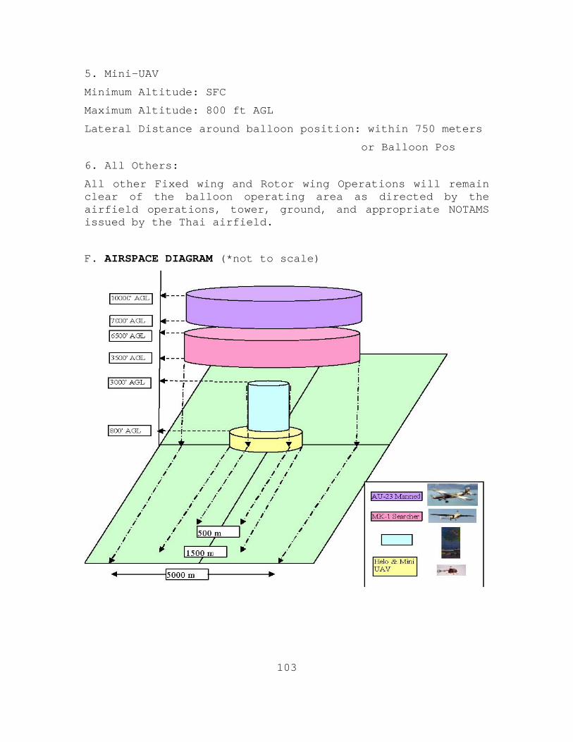
103
5. Mini-UAV
Minimum Altitude: SFC
Maximum Altitude: 800 ft AGL
Lateral Distance around balloon position: within 750 meters
or Balloon Pos
6. All Others:
All other Fixed wing and Rotor wing Operations will remain clear of the balloon operating area as directed by the airfield operations, tower, ground, and appropriate NOTAMS issued by the Thai airfield.
F. AIRSPACE DIAGRAM (*not to scale)
104
G. REQUESTED HOST NATION SUPPORT FOR AIR OPERATIONS
1. Thailand Airfield:
• Provide one vehicle equipped with airfield radios capable of communication with tower and capable of accessing Balloon operating area. (light 4x4)
• Issue appropriate NOTAMS for COASTS demonstration.
• Attend initial Confirmation brief on 22 March.
• Attend daily air operations briefing upon COASTS team daily arrival to Wing 2 operating area.
• Clear airspace as appropriate for COASTS Air Operations.
2. Thai UAV squadron:
• Attend initial Confirmation brief on 22 March.
• Attend daily air operations briefing upon COASTS team daily arrival to Wing 2 operating area for those days requiring Searcher Mk1 support.
• Issue any NOTAMS specific to Searcher Mk1 UAV operations in the vicinity of the Wing 2 Airfield.
3. Thai Helicopter Squadron:
• Attend initial Confirmation brief on 22 March.
• Attend daily air operations briefing upon COASTS team daily arrival to Wing 2 operating area for those days requiring helicopter support.
• Provide logistical support to/from Mountain Facility. Thai C-130 Squadron:
o Attend initial Confirmation brief on 22 March.
o Provide logistical support to/from BKK and Wing 2 Airfield.
o Notify NPS Air Marshall, Capt Thomason, of any conflicts or problems with daily transportation flights to Wing 2 Airfield.
105
H. NPS TASKS:
• Using provided radio com vehicle, notify airfield tower of NPS Balloon and UAV Deployment
• Conduct initial confirmation brief on 22 March in order to complete and solidify operating rules and timelines.
• Conduct daily confirmation briefing for all air operations scheduled for that day in order to communicate the plan of day for operations
I. OPERATING AIRFIELD INFORMATION
KHOK KATHIAM TWR 122.6 Mhz/238.6 Mhz
KHOK KATHIAM, VTBL
N 14.87460° E 100.66335° (47P PS 78949 45123) 98
ID: TH25973
Name: KHOK KATHIAM
Country: Thailand
Location: N 14.87460° E 100.66335°
(WGS84)
Elevation: 98 ft
Longest Usable Runway Length: 7252 ft
ICAO Code: VTBL
FAA ID: N
Type: Active Military Airport
Magnetic Var: 0.5W
Runway Information:
ID Displd Thresh Dim(LxW ft)
Mag Hdg Latitude Longitude
05 0 4435x148 047 N 14.86938° E 100.65763°
23 0 4435x148 227 N 14.87774° E 100.66679°
10 0 600x64 96.5 N 14.88634° E

106
100.66083°
28 0 600x64 276.5 N 14.88617° E 100.66254°
16 467 7252x148 161 N 14.88390° E 100.65993°
34 0 7252x148 341 N 14.86509
107
APPENDIX A5: THAI AU-23 FIXED WING AIRCRAFT
A. CHARACTERISTICS
1. The Au-23 is considered a mini-gunship.
2. Nicknamed “Credible Chase”
B. SPECIFICATIONS
1. Span: 49 ft. 8 in.
2. Length: 36 ft. 10 in.
3. Height: 14 ft. 4 in.
4. Weight: 6,100 lbs. maximum gross
5. Engine: Garrett TPE 331-1-101F turboprop of 650 hp.
C. CREW
3-pilot, copilot, gunner. In transport configuration, the aircraft could carry 6 passengers or 5 troops with field gear or 1 litter patient, 3 ambulatory patients and 1 medical attendant.
D. ARMAMENT
One XM-197 20 mm side firing cannon plus up to 1925 lbs. of external stores on five pylons - two on each wing (1400 lbs. of stores max.) and a center fuselage pylon (525 lbs. of stores max.) - In combat evaluations, the maximum ordnance load was about 1300 lbs. The aircraft was also evaluated with side firing XM 93 7.62 mm mini-gun, XM 59 .50-cal. machine gun and XMU-470 20 mm fixed side firing gun pods. Ordnance tested included SUU-11 gun pods, 2.75" rocket pods, BDU 33 with 25 lb. bomblets, MK 81 250 lb. bombs, MK 82 500 lb. bombs, BLU-118 500 lb. napalm canister, CBU-55 500 lb. cluster bomb unit, MK-24 flares, ADU-272 canisters, smoke grenades and propaganda leaflet dispensers.
E. PERFORMANCE
1. Maximum speed: 148 knots at take-off power, 5,000 feet altitude, 6,000 lbs. gross weight
2. Cruising speed: 142 knots at maximum continuous power
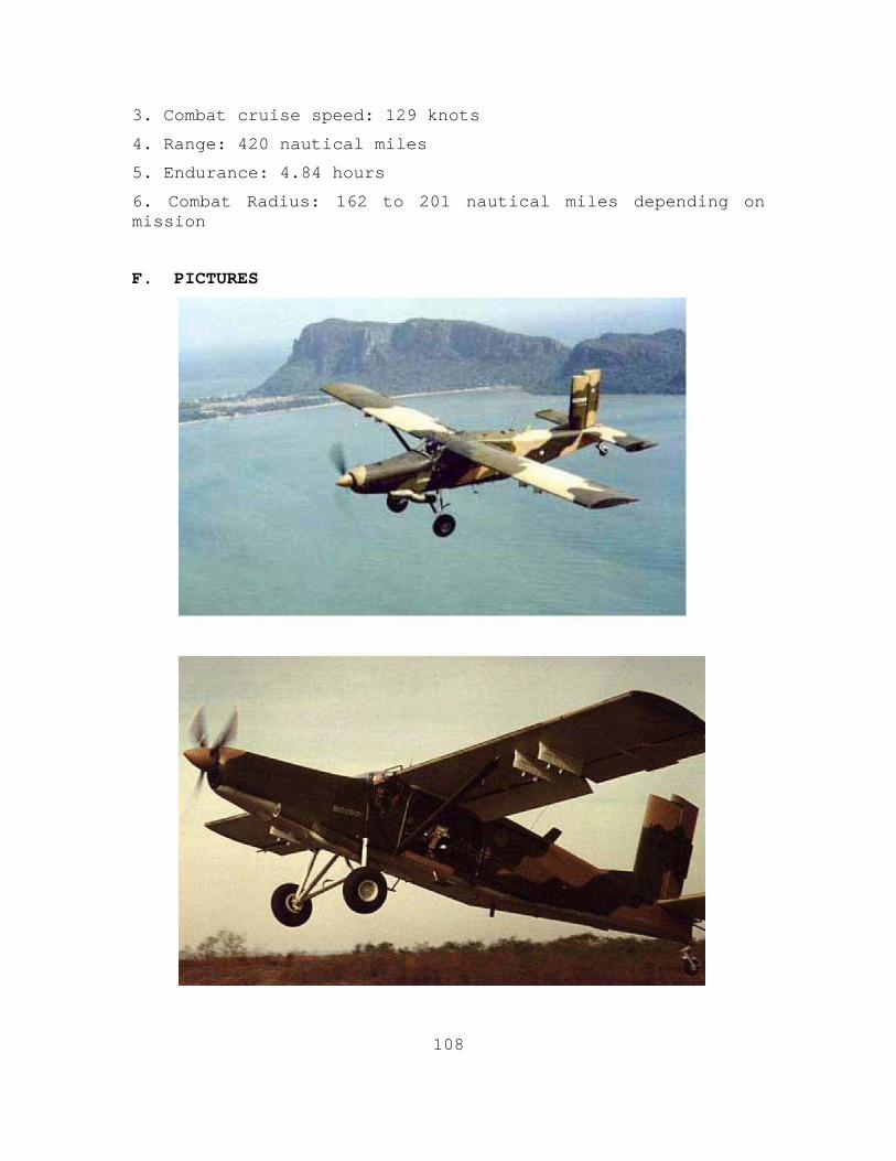
108
3. Combat cruise speed: 129 knots
4. Range: 420 nautical miles
5. Endurance: 4.84 hours
6. Combat Radius: 162 to 201 nautical miles depending on mission
F. PICTURES
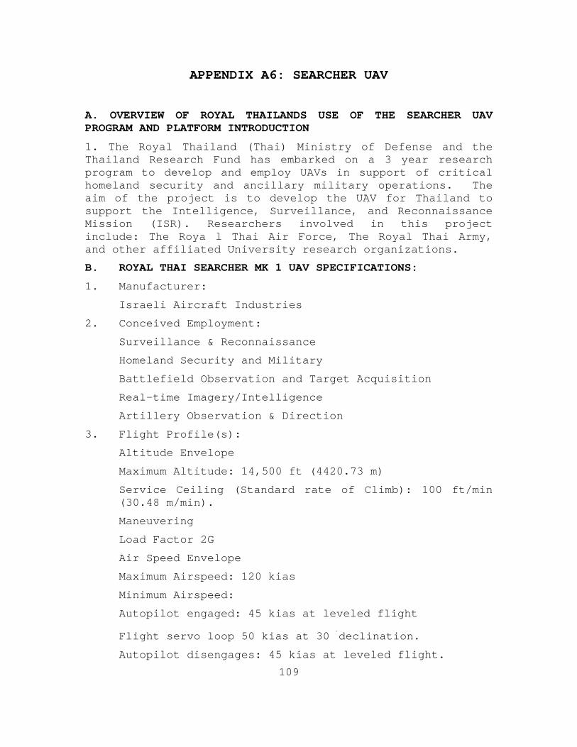
109
APPENDIX A6: SEARCHER UAV
A. OVERVIEW OF ROYAL THAILANDS USE OF THE SEARCHER UAV PROGRAM AND PLATFORM INTRODUCTION
1. The Royal Thailand (Thai) Ministry of Defense and the Thailand Research Fund has embarked on a 3 year research program to develop and employ UAVs in support of critical homeland security and ancillary military operations. The aim of the project is to develop the UAV for Thailand to support the Intelligence, Surveillance, and Reconnaissance Mission (ISR). Researchers involved in this project include: The Roya l Thai Air Force, The Royal Thai Army, and other affiliated University research organizations.
B. ROYAL THAI SEARCHER MK 1 UAV SPECIFICATIONS:
1. Manufacturer:
Israeli Aircraft Industries
2. Conceived Employment:
Surveillance & Reconnaissance
Homeland Security and Military
Battlefield Observation and Target Acquisition
Real-time Imagery/Intelligence
Artillery Observation & Direction
3. Flight Profile(s):
Altitude Envelope
Maximum Altitude: 14,500 ft (4420.73 m)
Service Ceiling (Standard rate of Climb): 100 ft/min (30.48 m/min).
Maneuvering
Load Factor 2G
Air Speed Envelope
Maximum Airspeed: 120 kias
Minimum Airspeed:
Autopilot engaged: 45 kias at leveled flight
Flight servo loop 50 kias at 30�declination.
Autopilot disengages: 45 kias at leveled flight.
110
Rate mode: 50 kias at 30�declination.
85 kias at 60�declination.
Stall airspeed: 42 kias at maximum weight.
Circling airspeed: 55 kias.
Decent for landing Airspeed: 65 kias.
Landing Airspeed:
Headwind component <12 knots: 60 kias.
Headwind component > 12 knots: 60+5 (Crosswind – 12 kias).
4. Performance Characteristics:
Input Power: Generator and GCU:
Power: 2000w.
Nominal Voltage: 28Vdc.
Minimum Voltage: 28Vdc.
Voltage quality: MIL-STD-704A.
Maximum Voltage: 32Vdc.
Ripple: Less than 4 VP-P.
C. (IMPROVED) SEARCHER MK II SPECIFICATIONS
1. Unmanned aerial vehicles and autonomous underwater vehicles are both areas of research that promise to extend the battlefield and increase the awareness of homeland security and military forces. The following specifications are provided as discussion points and all information was obtained on the unclassified network/internet. The primary source of this information was provided at the Israeli Aircraft Industries world wide web address as follows: http://www.iai.co.il/site/en/iai.asp?pi=18894. A promotion kit for the Searcher MK II may be obtained at the following wed address:
http://www.iai.co.il/STORAGE/files/4/15744.pdf.
1. Flight Profile(s)
• **Maximum Altitude: 16,000 – 20,000 ft
• 4876 m – 6096 m
111
• **Maximum Range: 200km (Direct Line of Sight)
• 250 w/ aid of airborne (UAV) platform
• **Maximum Endurance / Loiter: 12 – 15 hours
2. Datalinks and Payload information/configurations.
• Standard MOSP (TV & IR Combi) or SAR EL/M 2055
• IAI MOSP (Multi-Mission Optronic Stabilized Payload) combined TV/FLIR and/or air data relay are Standard
• Direct line-of-sight datalink, UAV airborne data relay for beyond-line-of-sight datalink.
• Dual real-time command uplink
• Single real-time data and video downlink ability
• Frequencies: Payload specific?
• Autonomous return on datalink loss *Maximum Payload Weight: 100kg (220lbs)
3. Operational Modes
• Real-time payload and UAV control
• GPS based interuptable airborne mission controller with real-time manual interrupt capability
4. Launch and Recovery
• Automatic Take-off and Landing Capable
• Take-off Weight 426 kg (940 lbs)
5. Airframe Dimensions and specifics
• Wing Span: 8.55 m (28.10.ft)
• Length 5.85m (19.2ft)
• Powerplant: Rotary engine (73 hp)
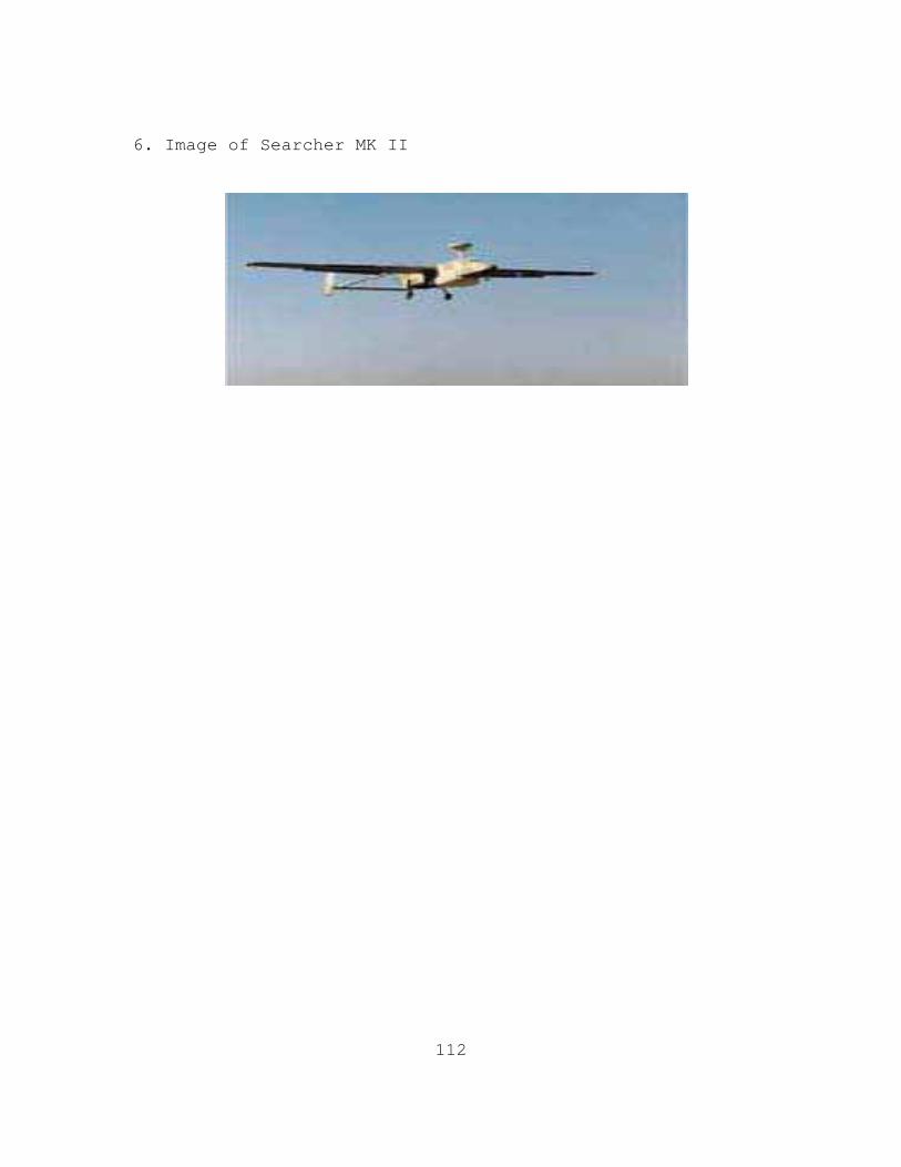
112
6. Image of Searcher MK II
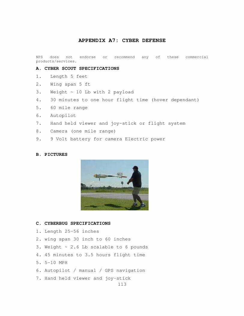
113
APPENDIX A7: CYBER DEFENSE
NPS does not endorse or recommend any of these commercial products/services.
A. CYBER SCOUT SPECIFICATIONS
1. Length 5 feet
2. Wing span 5 ft
3. Weight ~ 10 Lb with 2 payload
4. 30 minutes to one hour flight time (hover dependant)
5. 60 mile range
6. Autopilot
7. Hand held viewer and joy-stick or flight system
8. Camera (one mile range)
9. 9 Volt battery for camera Electric power
B. PICTURES
C. CYBERBUG SPECIFICATIONS
1. Length 25-56 inches
2. wing span 30 inch to 60 inches
3. Weight ~ 2.6 Lb scalable to 6 pounds
4. 45 minutes to 3.5 hours flight time
5. 5-10 MPH
6. Autopilot / manual / GPS navigation
7. Hand held viewer and joy-stick
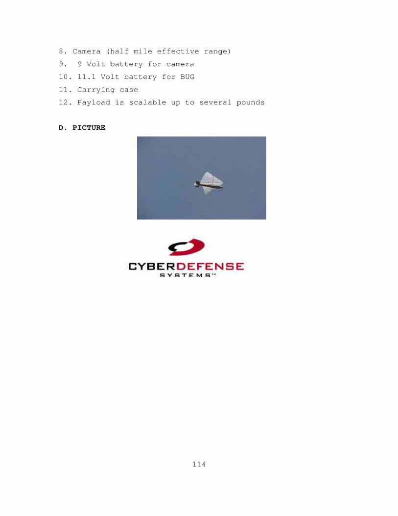
114
8. Camera (half mile effective range)
9. 9 Volt battery for camera
10. 11.1 Volt battery for BUG
11. Carrying case
12. Payload is scalable up to several pounds
D. PICTURE
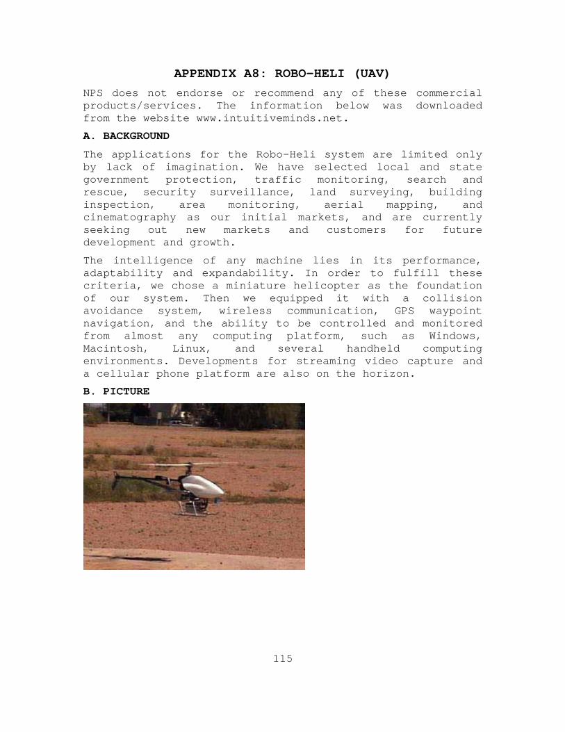
115
APPENDIX A8: ROBO-HELI (UAV)
NPS does not endorse or recommend any of these commercial products/services. The information below was downloaded from the website www.intuitiveminds.net.
A. BACKGROUND
The applications for the Robo-Heli system are limited only by lack of imagination. We have selected local and state government protection, traffic monitoring, search and rescue, security surveillance, land surveying, building inspection, area monitoring, aerial mapping, and cinematography as our initial markets, and are currently seeking out new markets and customers for future development and growth.
The intelligence of any machine lies in its performance, adaptability and expandability. In order to fulfill these criteria, we chose a miniature helicopter as the foundation of our system. Then we equipped it with a collision avoidance system, wireless communication, GPS waypoint navigation, and the ability to be controlled and monitored from almost any computing platform, such as Windows, Macintosh, Linux, and several handheld computing environments. Developments for streaming video capture and a cellular phone platform are also on the horizon.
B. PICTURE
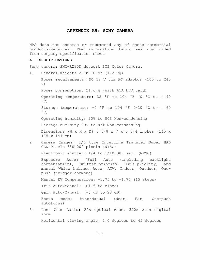
116
APPENDIX A9: SONY CAMERA
NPS does not endorse or recommend any of these commercial products/services. The information below was downloaded from company specification sheet.
A. SPECIFICATIONS
Sony camera: SNC-RZ30N Network PTZ Color Camera.
1. General Weight: 2 lb 10 oz (1.2 kg)
Power requirements: DC 12 V via AC adaptor (100 to 240 V)
Power consumption: 21.6 W (with ATA HDD card)
Operating temperature: 32 °F to 104 °F (0 °C to + 40 °C)
Storage temperature: -4 °F to 104 °F (-20 °C to + 60 °C)
Operating humidity: 20% to 80% Non-condensing
Storage humidity 20% to 95% Non-condensing
Dimensions (W x H x D) 5 5/8 x 7 x 5 3/4 inches (140 x 175 x 144 mm)
2. Camera Imager: 1/6 type Interline Transfer Super HAD CCD Pixels 680,000 pixels (NTSC)
Electronic shutter: 1/4 to 1/10,000 sec. (NTSC)
Exposure Auto: [Full Auto (including backlight compensation), Shutter-priority, Iris-priority] and manual White balance Auto, ATW, Indoor, Outdoor, One-push (trigger command)
Manual EV Compensation: -1.75 to +1.75 (15 steps)
Iris Auto/Manual: (F1.6 to close)
Gain Auto/Manual: (-3 dB to 28 dB)
Focus mode: Auto/Manual (Near, Far, One-push autofocus)
3. Lens Zoom Ratio: 25x optical zoom, 300x with digital zoom
Horizontal viewing angle: 2.0 degrees to 45 degrees
117
Focal length: f = 2.4 mm to 60 mm F-number F1.6 (wide), F2.7 (tele)
Minimum object distance Tele: 800 mm Wide: 30 mm
4. System/Network CPU: 32-bit RISC processor RAM 32 MB
(includes 8 MB alarm buffer)
Embedded flash memory: 8 MB Resolution 736 x 480, 640 x 480, 320 x 240, 160 x 120 (NTSC)
Compression JPEG Compression ratio: 1/5 ~ 1/60 (10 steps)
Frame rate: 30 fps max. (640 x 480) (NTSC)*
Protocols DHCP, TCP/IP, HTTP, ARP, FTP, SMTP, ICMP, and SNMP
* Depending on network environment
5. Interfaces:
Ethernet
100Base-TX /10Base-T (RJ-45)
PCMCIA Type II x 2
Video Output Analog Composite (BNC x1)
Sensor in 3 Alarm out 2 Serial IF RS-232C/485 (transparency only)
6. Analog Video Output Signal system
SNC-RZ30N (NTSC)
Sync system Internal Horizontal resolution
480 TV lines
S/N ratio 48 dB Min.
Illumination 3 lx (color)
7. Pan/Tilt Pan angle: -170 to +170 degrees
Pan speed: 2 sec./340 degrees
Tilt angle: -90 to +25 degrees
Tilt speed: 1.5 sec./115 degrees
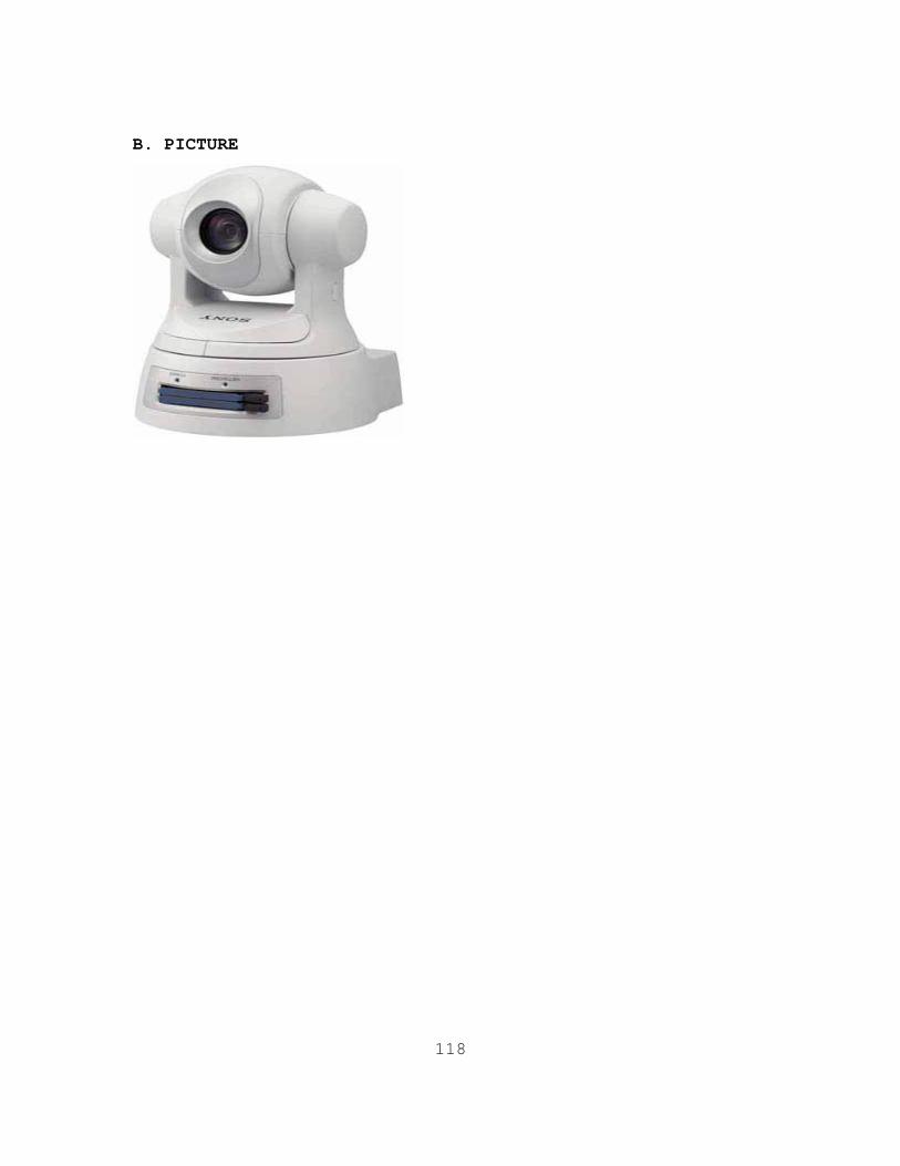
118
B. PICTURE
119
APPENDIX A10. CROSSBOW SENSOR GRID
NPS does not endorse or recommend any of these commercial products/services. The information below was downloaded from the website www.xbow.com.
A. BACKGROUND
Crossbow Technology is the leading end-to-end solutions supplier in wireless sensor networks and the largest manufacturer of Smart Dust wireless sensors. Crossbow has deployed wireless sensors networks for large-scale commercial use, and Crossbow is currently supplying its Smart Dust products and services to several Fortune 100 companies. Crossbow’s wireless sensor networking platform enables powerful, wireless, and automated data collection and monitoring systems.
1. MOTES / RADIOS. The hardware platform consists of Processor/Radio boards (MPR) commonly referred to as Motes. These battery-powered devices run Crossbow's XMesh self-forming, micro-power, networking stack. In addition to running the XMesh networking stack, each Mote runs the open-source TinyOS operating system which provides low-level event and task management.
2. SENSORS. Sensor and data acquisition cards (MTS and MDA) mate directly to the Mote Processor Radio boards. The industry's widest range of sensor support includes both direct sensing as well as interfaces for external sensors.
3. GATEWAYS . The Stargate ‘Gateway’ and the Mote Interface Boards (MIB), allow developers to interface Motes to PCs, PDAs, the WWW, and existing wired/wireless networks and protocols.
4. CUSTOMIZATION. The TinyOS operating system is open-source, extendable, and scalable. Code modules are wired together allowing fluent-C programmers to rapidly customize existing applications written and distributed by Crossbow Technology
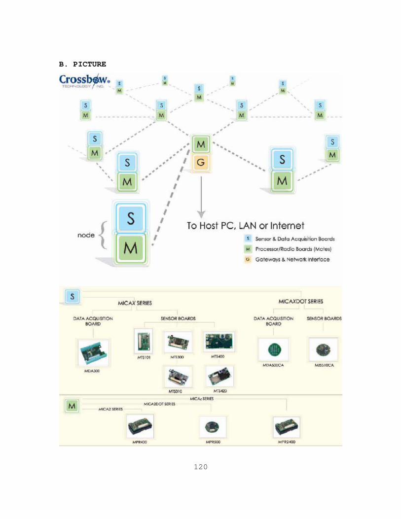
120
B. PICTURE
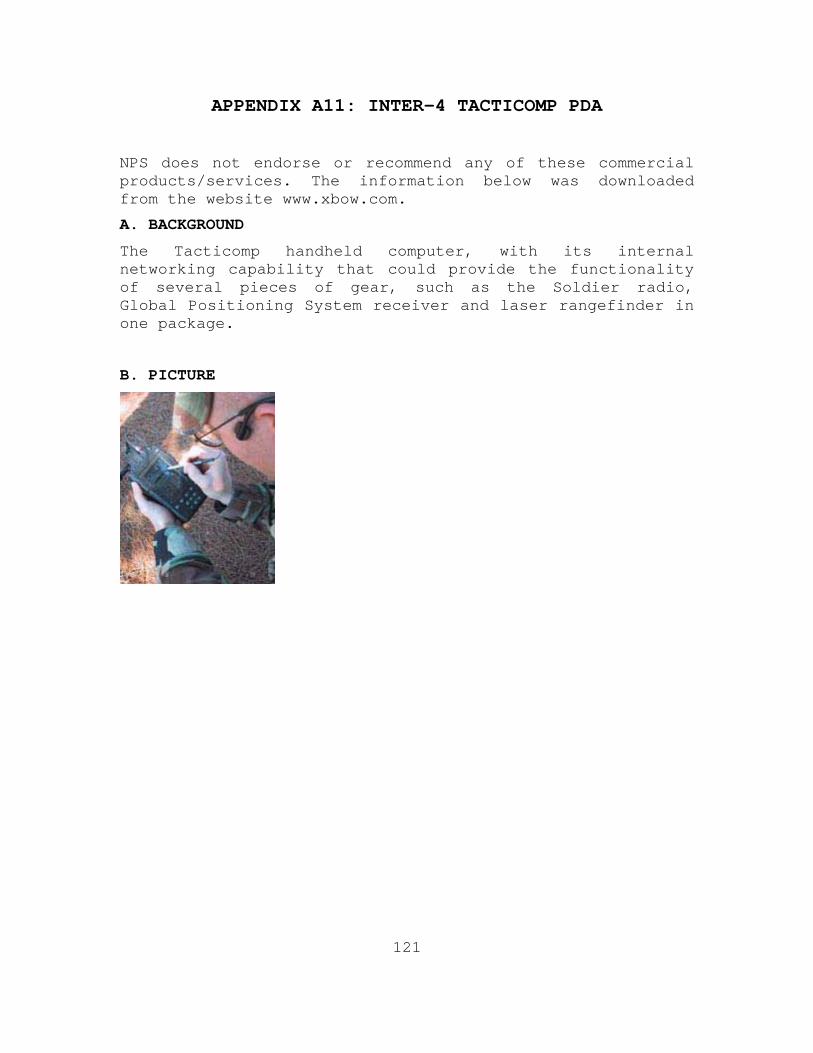
121
APPENDIX A11: INTER-4 TACTICOMP PDA
NPS does not endorse or recommend any of these commercial products/services. The information below was downloaded from the website www.xbow.com.
A. BACKGROUND
The Tacticomp handheld computer, with its internal networking capability that could provide the functionality of several pieces of gear, such as the Soldier radio, Global Positioning System receiver and laser rangefinder in one package.
B. PICTURE
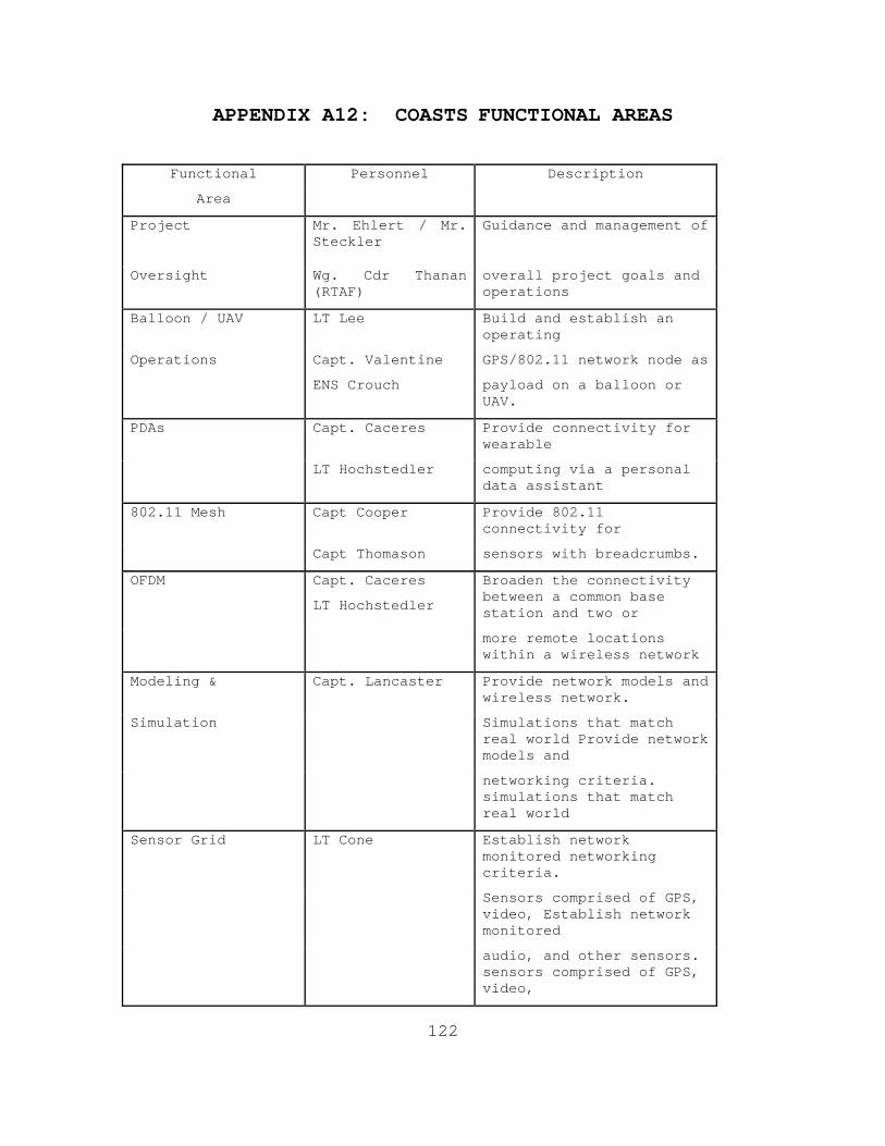
122
APPENDIX A12: COASTS FUNCTIONAL AREAS
Functional Personnel Description
Area
Project
Mr. Ehlert / Mr. Steckler
Guidance and management of
Oversight Wg. Cdr Thanan (RTAF)
overall project goals and operations
Balloon / UAV LT Lee Build and establish an operating
Operations Capt. Valentine GPS/802.11 network node as
ENS Crouch payload on a balloon or UAV.
PDAs Capt. Caceres Provide connectivity for wearable
LT Hochstedler computing via a personal data assistant
802.11 Mesh Capt Cooper Provide 802.11 connectivity for
Capt Thomason sensors with breadcrumbs.
OFDM Capt. Caceres
LT Hochstedler
Broaden the connectivity between a common base station and two or
more remote locations within a wireless network
Modeling & Capt. Lancaster Provide network models and wireless network.
Simulation Simulations that match real world Provide network models and
networking criteria. simulations that match real world
Sensor Grid LT Cone Establish network monitored networking criteria.
Sensors comprised of GPS, video, Establish network monitored
audio, and other sensors. sensors comprised of GPS, video,
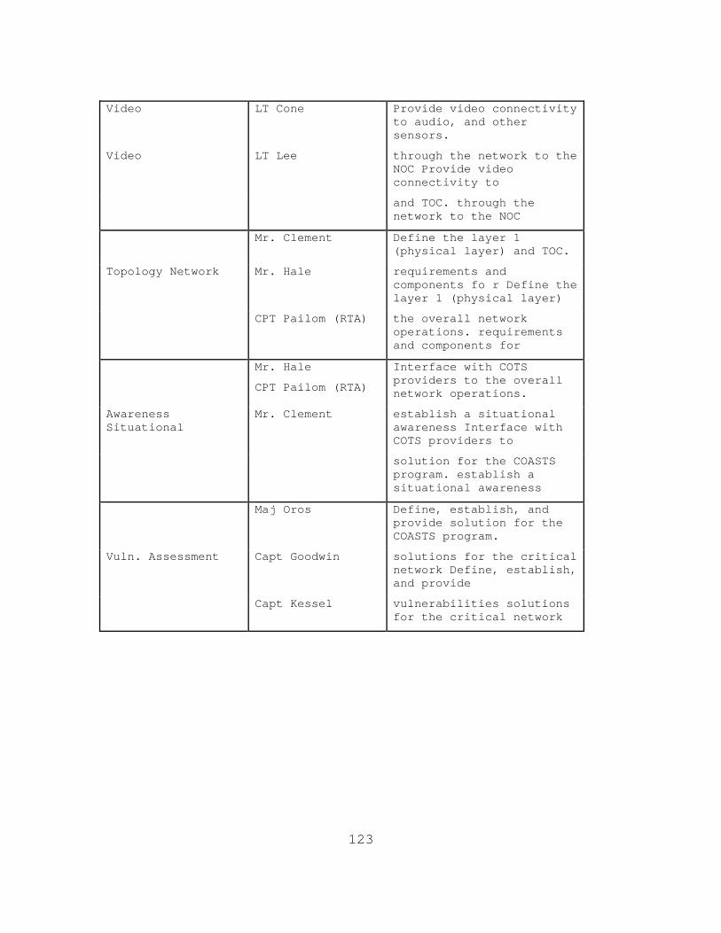
123
Video LT Cone Provide video connectivity
to audio, and other sensors.
Video LT Lee through the network to the NOC Provide video connectivity to
and TOC. through the network to the NOC
Mr. Clement Define the layer 1 (physical layer) and TOC.
Topology Network Mr. Hale
requirements and components fo r Define the layer 1 (physical layer)
CPT Pailom (RTA) the overall network operations. requirements and components for
Mr. Hale
CPT Pailom (RTA)
Interface with COTS providers to the overall network operations.
Awareness Situational
Mr. Clement establish a situational awareness Interface with COTS providers to
solution for the COASTS program. establish a situational awareness
Maj Oros Define, establish, and provide solution for the COASTS program.
Vuln. Assessment Capt Goodwin
solutions for the critical network Define, establish, and provide
Capt Kessel vulnerabilities solutions for the critical network
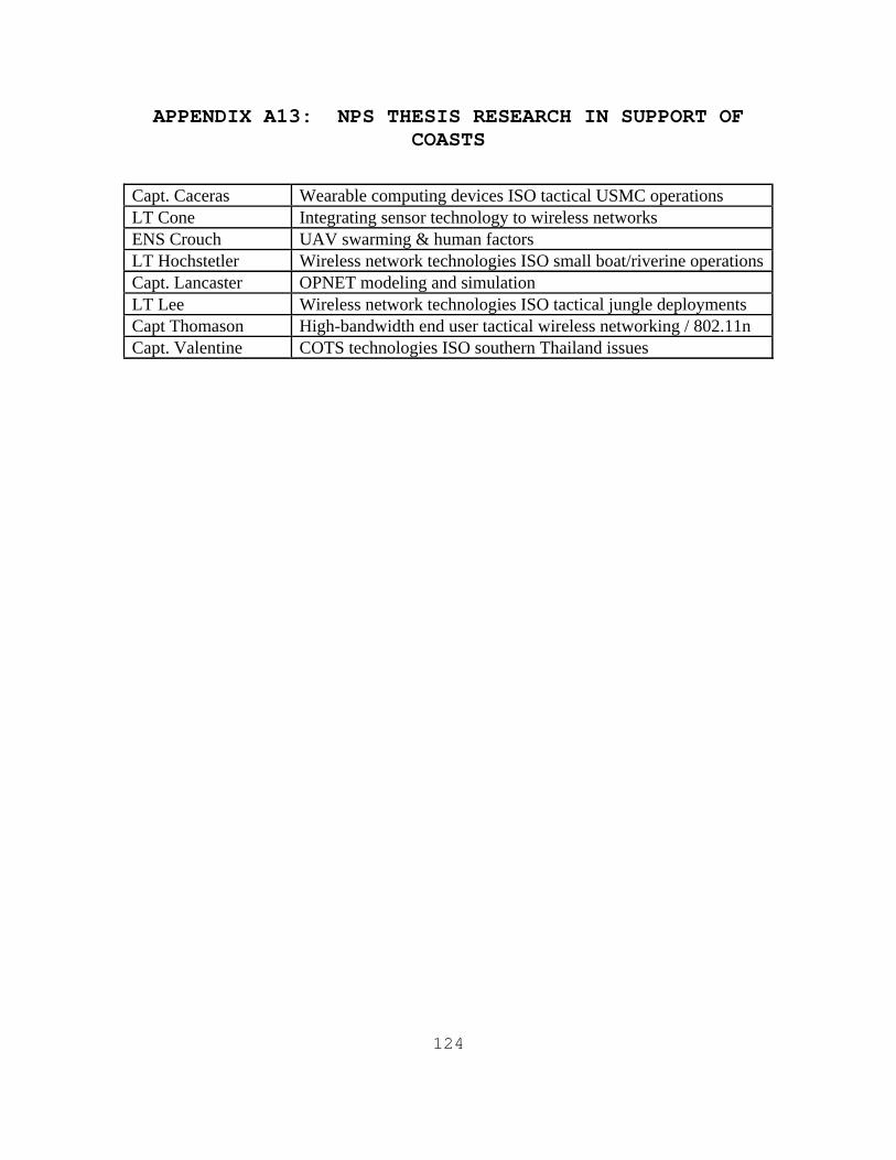
124
APPENDIX A13: NPS THESIS RESEARCH IN SUPPORT OF COASTS
Capt. Caceras Wearable computing devices ISO tactical USMC operations LT Cone Integrating sensor technology to wireless networks ENS Crouch UAV swarming & human factors LT Hochstetler Wireless network technologies ISO small boat/riverine operations Capt. Lancaster OPNET modeling and simulation LT Lee Wireless network technologies ISO tactical jungle deployments Capt Thomason High-bandwidth end user tactical wireless networking / 802.11n Capt. Valentine COTS technologies ISO southern Thailand issues
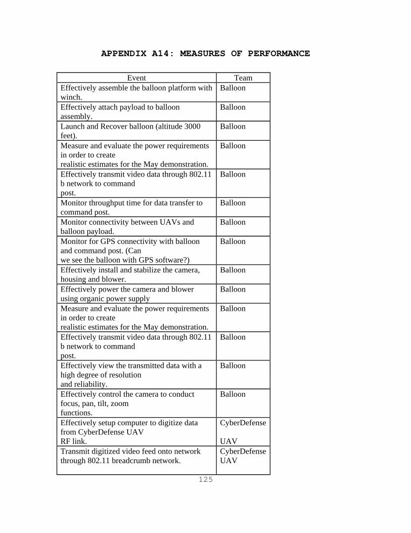
125
APPENDIX A14: MEASURES OF PERFORMANCE
Event Team
Effectively assemble the balloon platform with winch.
Balloon
Effectively attach payload to balloon assembly.
Balloon
Launch and Recover balloon (altitude 3000 feet).
Balloon
Measure and evaluate the power requirements in order to create
Balloon
realistic estimates for the May demonstration. Effectively transmit video data through 802.11 b network to command
Balloon
post. Monitor throughput time for data transfer to command post.
Balloon
Monitor connectivity between UAVs and balloon payload.
Balloon
Monitor for GPS connectivity with balloon and command post. (Can
Balloon
we see the balloon with GPS software?) Effectively install and stabilize the camera, housing and blower.
Balloon
Effectively power the camera and blower using organic power supply
Balloon
Measure and evaluate the power requirements in order to create
Balloon
realistic estimates for the May demonstration. Effectively transmit video data through 802.11 b network to command
Balloon
post. Effectively view the transmitted data with a high degree of resolution
Balloon
and reliability. Effectively control the camera to conduct focus, pan, tilt, zoom
Balloon
functions. Effectively setup computer to digitize data from CyberDefense UAV
CyberDefense
RF link. UAV Transmit digitized video feed onto network through 802.11 breadcrumb network.
CyberDefense UAV
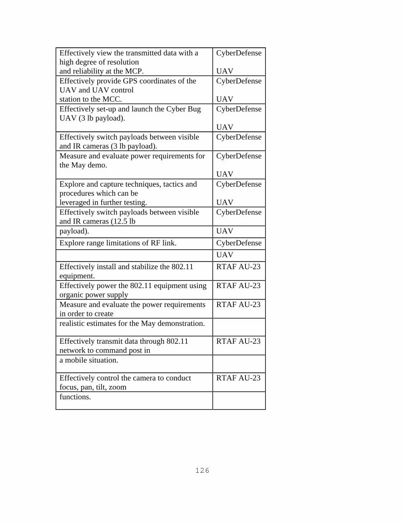
126
Effectively view the transmitted data with a high degree of resolution
CyberDefense
and reliability at the MCP. UAV Effectively provide GPS coordinates of the UAV and UAV control
CyberDefense
station to the MCC. UAV Effectively set-up and launch the Cyber Bug UAV (3 lb payload).
CyberDefense
UAV Effectively switch payloads between visible and IR cameras (3 lb payload).
CyberDefense
Measure and evaluate power requirements for the May demo.
CyberDefense
UAV Explore and capture techniques, tactics and procedures which can be
CyberDefense
leveraged in further testing. UAV Effectively switch payloads between visible and IR cameras (12.5 lb
CyberDefense
payload). UAV Explore range limitations of RF link. CyberDefense UAV Effectively install and stabilize the 802.11 equipment.
RTAF AU-23
Effectively power the 802.11 equipment using organic power supply
RTAF AU-23
Measure and evaluate the power requirements in order to create
RTAF AU-23
realistic estimates for the May demonstration.
Effectively transmit data through 802.11 network to command post in
RTAF AU-23
a mobile situation.
Effectively control the camera to conduct focus, pan, tilt, zoom
RTAF AU-23
functions.
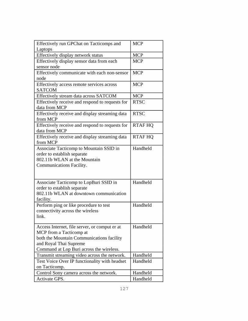
127
Effectively run GPChat on Tacticomps and Laptops
MCP
Effectively display network status MCP Effectively display sensor data from each sensor node
MCP
Effectively communicate with each non-sensor node
MCP
Effectively access remote services across SATCOM
MCP
Effectively stream data across SATCOM MCP Effectively receive and respond to requests for data from MCP
RTSC
Effectively receive and display streaming data from MCP
RTSC
Effectively receive and respond to requests for data from MCP
RTAF HQ
Effectively receive and display streaming data from MCP
RTAF HQ
Associate Tacticomp to Mountain SSID in order to establish separate
Handheld
802.11b WLAN at the Mountain Communications Facility.
Associate Tacticomp to LopBuri SSID in order to establish separate
Handheld
802.11b WLAN at downtown communication facility.
Perform ping or like procedure to test connectivity across the wireless
Handheld
link.
Access Internet, file server, or comput er at MCP from a Tacticomp at
Handheld
both the Mountain Communications facility and Royal Thai Supreme
Command at Lop Buri across the wireless. Transmit streaming video across the network. Handheld Test Voice Over IP functionality with headset on Tacticomp.
Handheld
Control Sony camera across the network. Handheld Activate GPS. Handheld
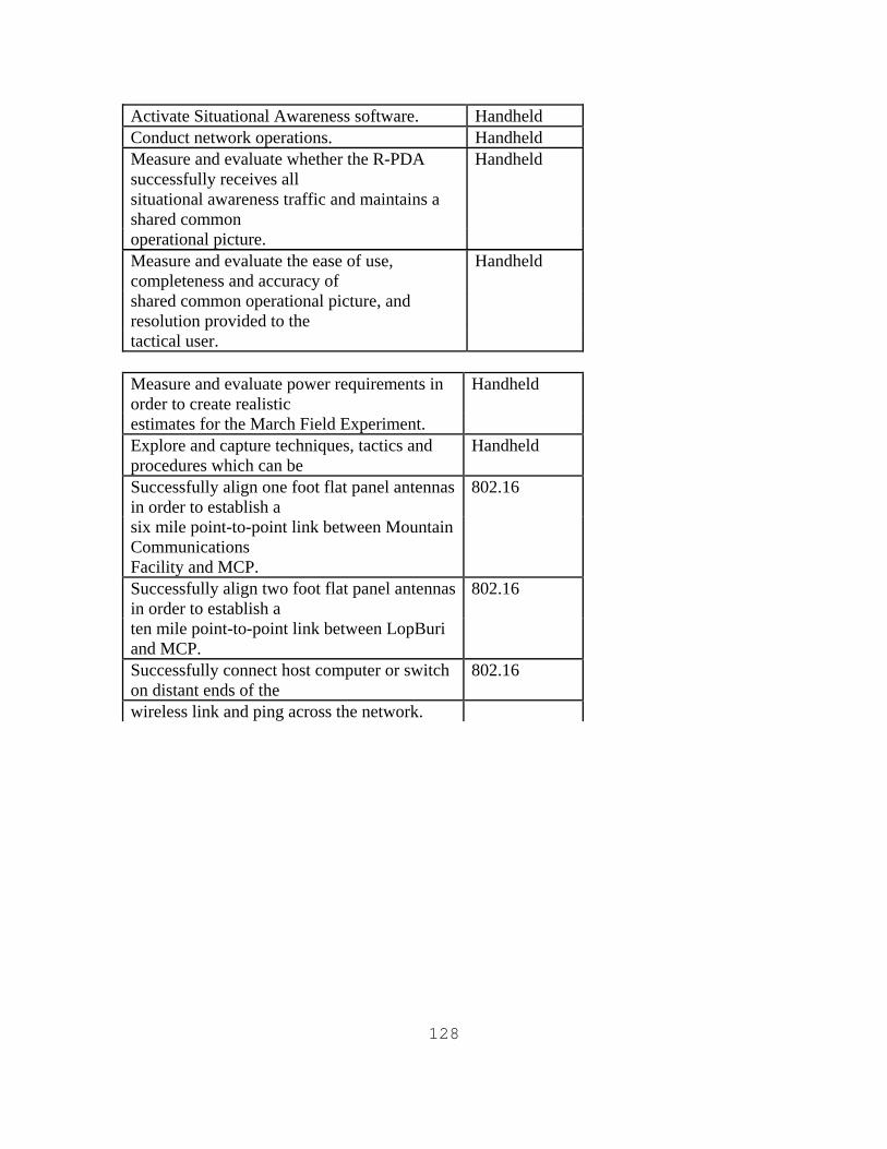
128
Activate Situational Awareness software. Handheld Conduct network operations. Handheld Measure and evaluate whether the R-PDA successfully receives all
Handheld
situational awareness traffic and maintains a shared common
operational picture. Measure and evaluate the ease of use, completeness and accuracy of
Handheld
shared common operational picture, and resolution provided to the
tactical user. Measure and evaluate power requirements in order to create realistic
Handheld
estimates for the March Field Experiment. Explore and capture techniques, tactics and procedures which can be
Handheld
Successfully align one foot flat panel antennas in order to establish a
802.16
six mile point-to-point link between Mountain Communications
Facility and MCP. Successfully align two foot flat panel antennas in order to establish a
802.16
ten mile point-to-point link between LopBuri and MCP.
Successfully connect host computer or switch on distant ends of the
802.16
wireless link and ping across the network.
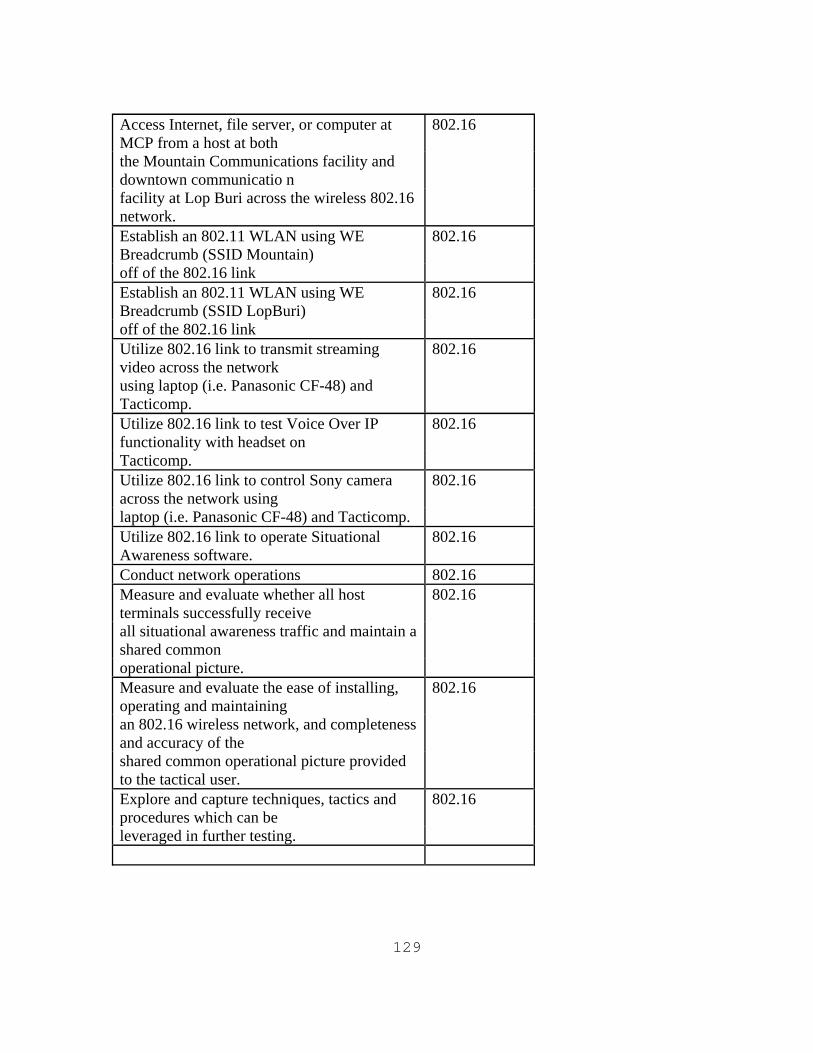
129
Access Internet, file server, or computer at MCP from a host at both
802.16
the Mountain Communications facility and downtown communicatio n
facility at Lop Buri across the wireless 802.16 network.
Establish an 802.11 WLAN using WE Breadcrumb (SSID Mountain)
802.16
off of the 802.16 link Establish an 802.11 WLAN using WE Breadcrumb (SSID LopBuri)
802.16
off of the 802.16 link Utilize 802.16 link to transmit streaming video across the network
802.16
using laptop (i.e. Panasonic CF-48) and Tacticomp.
Utilize 802.16 link to test Voice Over IP functionality with headset on
802.16
Tacticomp. Utilize 802.16 link to control Sony camera across the network using
802.16
laptop (i.e. Panasonic CF-48) and Tacticomp. Utilize 802.16 link to operate Situational Awareness software.
802.16
Conduct network operations 802.16 Measure and evaluate whether all host terminals successfully receive
802.16
all situational awareness traffic and maintain a shared common
operational picture. Measure and evaluate the ease of installing, operating and maintaining
802.16
an 802.16 wireless network, and completeness and accuracy of the
shared common operational picture provided to the tactical user.
Explore and capture techniques, tactics and procedures which can be
802.16
leveraged in further testing.
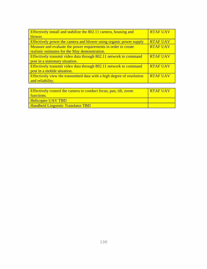
130
Effectively install and stabilize the 802.11 camera, housing and RTAF UAV blower. Effectively power the camera and blower using organic power supply RTAF UAV Measure and evaluate the power requirements in order to create RTAF UAV realistic estimates for the May demonstration. Effectively transmit video data through 802.11 network to command RTAF UAV post in a stationary situation. Effectively transmit video data through 802.11 network to command RTAF UAV post in a mobile situation. Effectively view the transmitted data with a high degree of resolution RTAF UAV and reliability. Effectively control the camera to conduct focus, pan, tilt, zoom RTAF UAV functions. Helicopter UAV TBD Handheld Linguistic Translator TBD
131
APPENDIX B. TETHERED BALLOON ASSEMBLY
Tethered Balloon Platform and GPS/802.11 Network Equipment and Assembly.
Table of Contents
I. Background II. Balloon Platform III. Attaching the Balloon to Platform IV. The Balloon V. Computer Network/Housing and Attaching to Balloon
I. Background
The COASTS proposed coalition field experimentation concept is modeled after a successful ongoing NPS-driven field experimentation program previously known as Surveillance and Targeting Network (STAN) and now called the Tactical Network Topology Field Experiment (TNT FE). NPS, in cooperation with U.S. Special Operations Command (USSOCOM) and several contractors, has been engaged in a Research and Development (R&D) program entitled STAN since FY2002. The program was initiated in support of a USSOCOM requirement for integrating emerging wireless local area network (WLAN) technologies with surveillance and targeting hardware/software systems to augment Special Operations Forces missions. TNT FE has grown significantly since inception to include 10-12 private sector companies demonstrating new hardware/software capabilities, several DoD organizations (led by NPS) introducing operational and tactical surveillance and targeting requirements, as well as other universities contributing solutions.
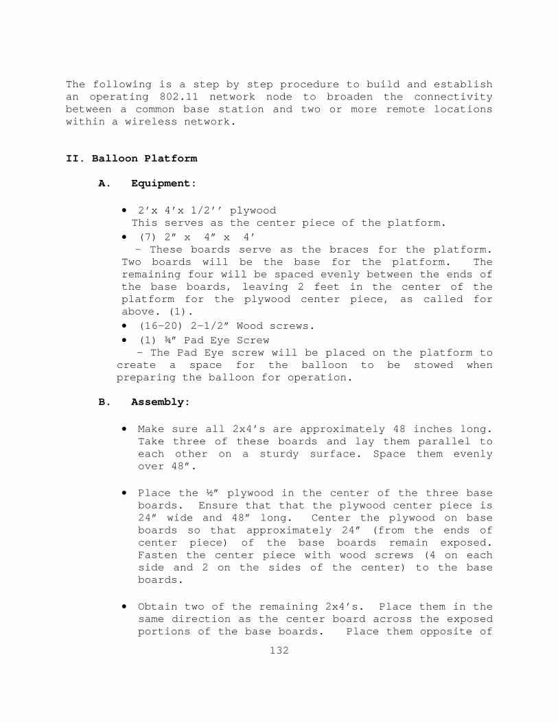
132
The following is a step by step procedure to build and establish an operating 802.11 network node to broaden the connectivity between a common base station and two or more remote locations within a wireless network. II. Balloon Platform
A. Equipment:
• 2’x 4’x 1/2’’ plywood This serves as the center piece of the platform.
• (7) 2” x 4” x 4’ - These boards serve as the braces for the platform. Two boards will be the base for the platform. The remaining four will be spaced evenly between the ends of the base boards, leaving 2 feet in the center of the platform for the plywood center piece, as called for above. (1). • (16-20) 2-1/2” Wood screws. • (1) ¾” Pad Eye Screw - The Pad Eye screw will be placed on the platform to create a space for the balloon to be stowed when preparing the balloon for operation.
B. Assembly:
• Make sure all 2x4’s are approximately 48 inches long. Take three of these boards and lay them parallel to each other on a sturdy surface. Space them evenly over 48”.
• Place the ½” plywood in the center of the three base
boards. Ensure that that the plywood center piece is 24” wide and 48” long. Center the plywood on base boards so that approximately 24” (from the ends of center piece) of the base boards remain exposed. Fasten the center piece with wood screws (4 on each side and 2 on the sides of the center) to the base boards.
• Obtain two of the remaining 2x4’s. Place them in the
same direction as the center board across the exposed portions of the base boards. Place them opposite of
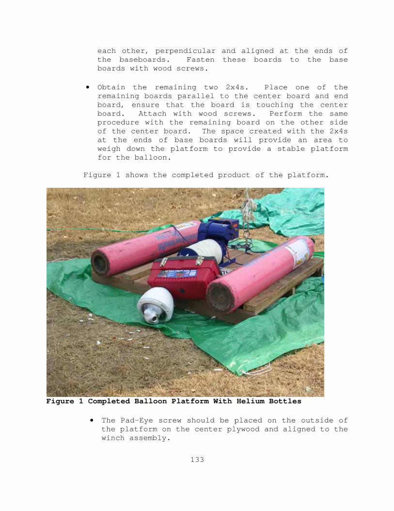
133
each other, perpendicular and aligned at the ends of the baseboards. Fasten these boards to the base boards with wood screws.
• Obtain the remaining two 2x4s. Place one of the
remaining boards parallel to the center board and end board, ensure that the board is touching the center board. Attach with wood screws. Perform the same procedure with the remaining board on the other side of the center board. The space created with the 2x4s at the ends of base boards will provide an area to weigh down the platform to provide a stable platform for the balloon.
Figure 1 shows the completed product of the platform.
Figure 1 Completed Balloon Platform With Helium Bottles
• The Pad-Eye screw should be placed on the outside of the platform on the center plywood and aligned to the winch assembly.
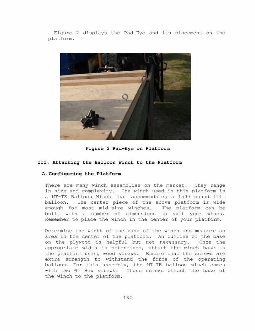
134
Figure 2 displays the Pad-Eye and its placement on the platform.
Figure 2 Pad-Eye on Platform
III. Attaching the Balloon Winch to the Platform A. Configuring the Platform There are many winch assemblies on the market. They range in size and complexity. The winch used in this platform is a MT-TE Balloon Winch that accommodates a 1500 pound lift balloon. The center piece of the above platform is wide enough for most mid-size winches. The platform can be built with a number of dimensions to suit your winch. Remember to place the winch in the center of your platform. Determine the width of the base of the winch and measure an area in the center of the platform. An outline of the base on the plywood is helpful but not necessary. Once the appropriate width is determined, attach the winch base to the platform using wood screws. Ensure that the screws are extra strength to withstand the force of the operating balloon. For this assembly, the MT-TE balloon winch comes with two ¾” Hex screws. These screws attach the base of the winch to the platform.
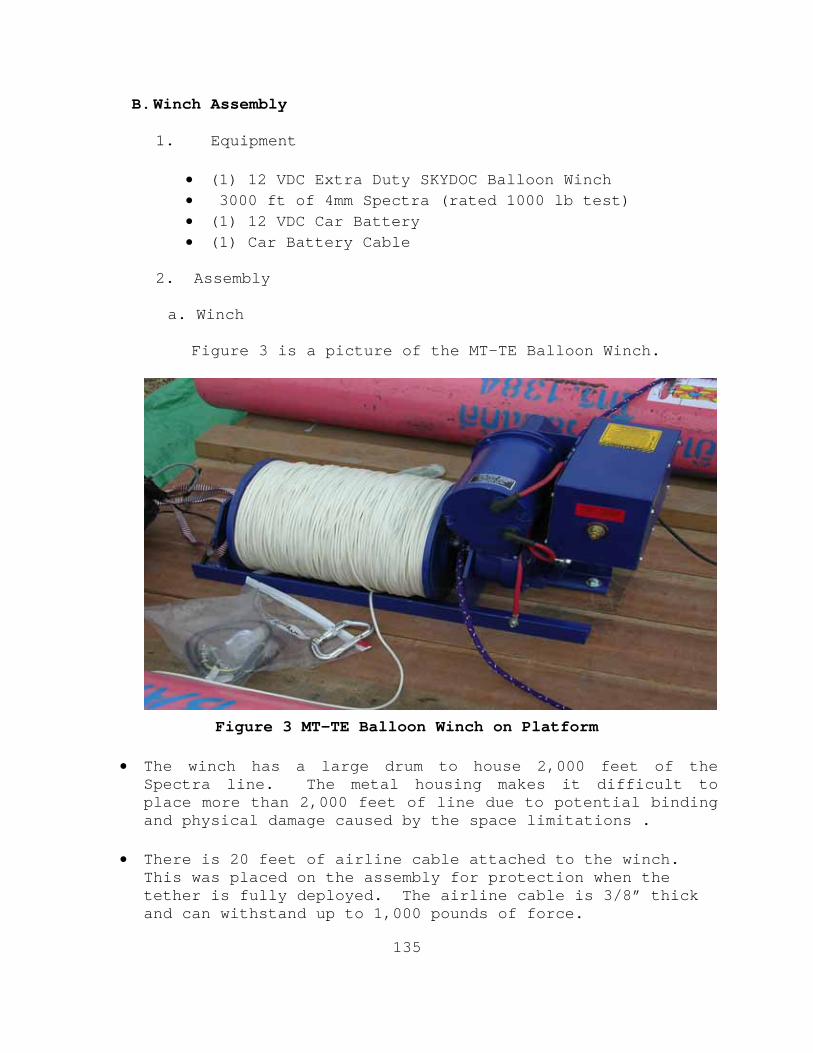
135
B. Winch Assembly
1. Equipment • (1) 12 VDC Extra Duty SKYDOC Balloon Winch • 3000 ft of 4mm Spectra (rated 1000 lb test) • (1) 12 VDC Car Battery • (1) Car Battery Cable
2. Assembly
a. Winch Figure 3 is a picture of the MT-TE Balloon Winch.
Figure 3 MT-TE Balloon Winch on Platform
• The winch has a large drum to house 2,000 feet of the Spectra line. The metal housing makes it difficult to place more than 2,000 feet of line due to potential binding and physical damage caused by the space limitations .
• There is 20 feet of airline cable attached to the winch.
This was placed on the assembly for protection when the tether is fully deployed. The airline cable is 3/8” thick and can withstand up to 1,000 pounds of force.
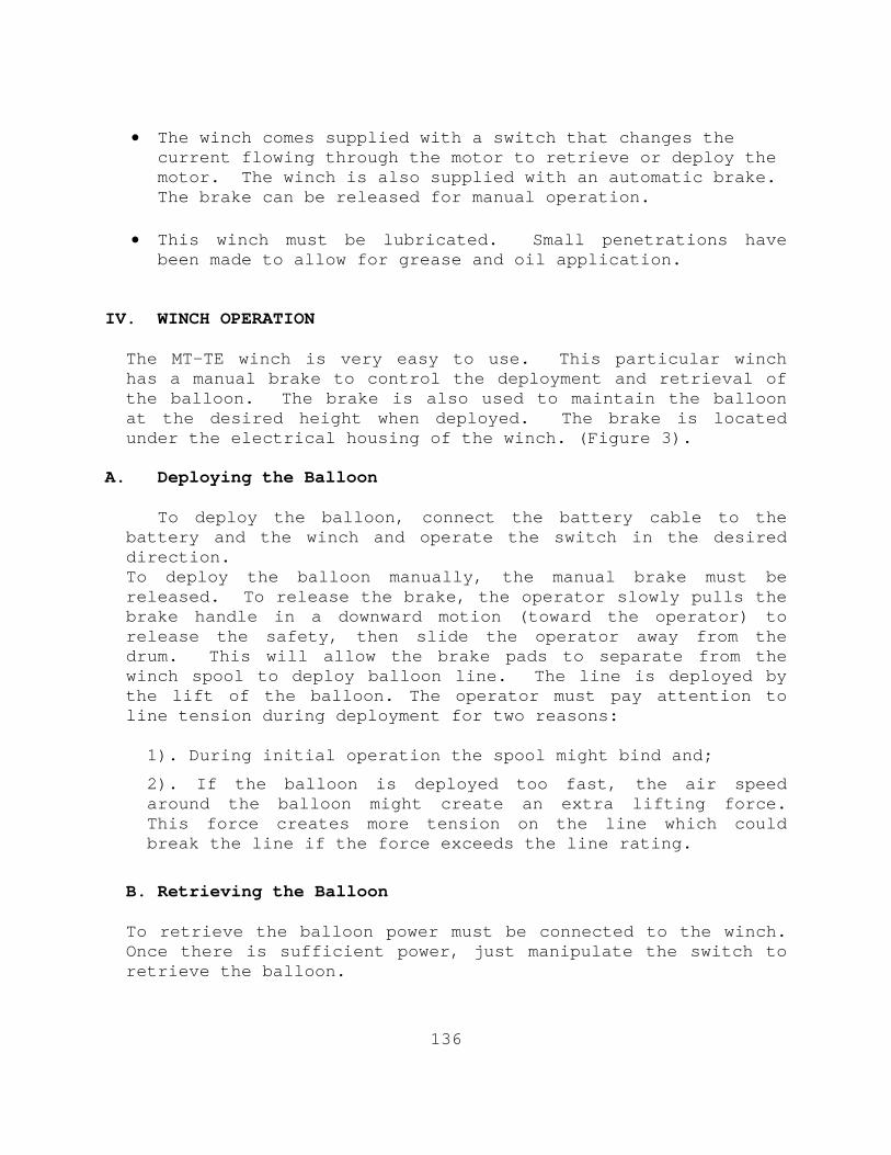
136
• The winch comes supplied with a switch that changes the
current flowing through the motor to retrieve or deploy the motor. The winch is also supplied with an automatic brake. The brake can be released for manual operation.
• This winch must be lubricated. Small penetrations have
been made to allow for grease and oil application.
IV. WINCH OPERATION
The MT-TE winch is very easy to use. This particular winch has a manual brake to control the deployment and retrieval of the balloon. The brake is also used to maintain the balloon at the desired height when deployed. The brake is located under the electrical housing of the winch. (Figure 3).
A. Deploying the Balloon
To deploy the balloon, connect the battery cable to the
battery and the winch and operate the switch in the desired direction. To deploy the balloon manually, the manual brake must be released. To release the brake, the operator slowly pulls the brake handle in a downward motion (toward the operator) to release the safety, then slide the operator away from the drum. This will allow the brake pads to separate from the winch spool to deploy balloon line. The line is deployed by the lift of the balloon. The operator must pay attention to line tension during deployment for two reasons:
1). During initial operation the spool might bind and;
2). If the balloon is deployed too fast, the air speed around the balloon might create an extra lifting force. This force creates more tension on the line which could break the line if the force exceeds the line rating.
B. Retrieving the Balloon To retrieve the balloon power must be connected to the winch. Once there is sufficient power, just manipulate the switch to retrieve the balloon.

137
Retrieving the Balloon
1. Manipulate the switch in the desired direction.
2. Using the carabineer, guide the line onto the spool so it will wind evenly onto the spool.
3. Once the balloon is retrieved, or at the desired
height, release the switch.
4. Attach the balloon tether to the platform through the Pad-Eye screw. This can be done using the carabineer through a loop through the main tether of the balloon. Attaching your balloon to the platform allows the operator to attach the payload or to deflate the balloon for removal.
V. The Balloon This balloon operation uses a 16.8 pound (minimum) lift balloon. The particular balloon for this operation was bought from Sky-Doc Balloons. This balloon is made out of polyurethane and filled with helium. The diameter of the balloon is approximately 13 feet. The balloon is equipped with an inflation/deflation tube. The balloon has 4 attachment strings that are fastened to a center ring. The ring is connected to the main Spectra tether. This balloon is delicate but the leakage rate is minimal. There are many balloons on the market. The important characteristics in searching for the best balloon for an operation are listed below:
• Lift (usually in pounds) • Material (strong plastic is best) • Wind sustainability • Operation Time (inflate/deflate time)
A. Equipment
1. (1) 800 lb lift balloon (Sky-Doc) 2. (1) 12 ft rope 3. (1) ¼” 10-15 ft Nylon rope 4. (2) 294 cu ft bottles of helium

138
5. (1) Air regulator with inlet/outlet pressure gauges 6. 15 ft of Tygon tubing 7. (1) Crescent wrench B. Inflating the balloon
1. The balloon comes in cellophane wrap. Remove the balloon from the wrap.
2. Layout the balloon and ensure that the 4 attachments (string)
are free from binding.
3. Attach the 12 ft rope to the top of the balloon. This will allow the operator a method to deflate the balloon when needed.
4. Open the inflating tube.
5. Attach the regulator to one of the helium bottles: a. The regulator will have two gauges. One gauge will monitor the pressure on the helium bottle and the other will monitor the pressure being applied to the balloon. Before installing the regulator to a bottle, ensure that the tygon tubing is attached to the outlet of the regulator. b. Insert the regulator to the top of the bottle. The regulator will have female threads and must be twisted on the bottle. Use the crescent wrench to tighten the connection. 6. Attach the balloon attachments to the attaching ring. 7. Attach the nylon rope to the winch. This is performed by tying a knot to join the ends of the rope to the winch line or by using some attaching device. It is recommended to use a carabineer or another attaching ring similar to the one on the balloon. Attaching the balloon to the winch will prevent the balloon from being lost when inflating. 8. Inflate the balloon a. Open the valve at the top of the regulator. This will allow the helium in the bottle to pressurize the regulator up to the outlet. The operator should see a fluctuation of the first gauge indicating that the there is pressure in the bottle.

139
b. Insert the tygon tubing in the inflation tube of the balloon.
c. Open the outlet valve to the balloon. Monitor the pressure coming out of the second gauge. When air is applied to the balloon, the operator should monitor the placement of the tygon tubing in the balloon to prevent damaging the balloon. The high pressure of the helium has the potential to rip the plastic of the balloon.
d. The balloon has an inflation indication attached to the
side of the balloon. It is a telltale indication similar to those found on the large ropes used on tugboats. When the line gets taught, the balloon is at max pressure. The balloon will take approximately 1-1/2” bottles to fill.
9. Secure filling by shutting the outlet valve of the regulator then the inlet valve.
10. Remove the tygon tubing from the balloon and shut the inflation tube.
11. The balloon is ready for operation.
C. Deflating the balloon
1. Retrieve the balloon and secure it to the platform. 2. Open the inflating tube 3. As the balloon deflates, the operator will be able to apply pressure to the outside of the balloon to fully deflate the balloon. 4. Stow the balloon. Figure 4 shows the balloon in stowed the position.
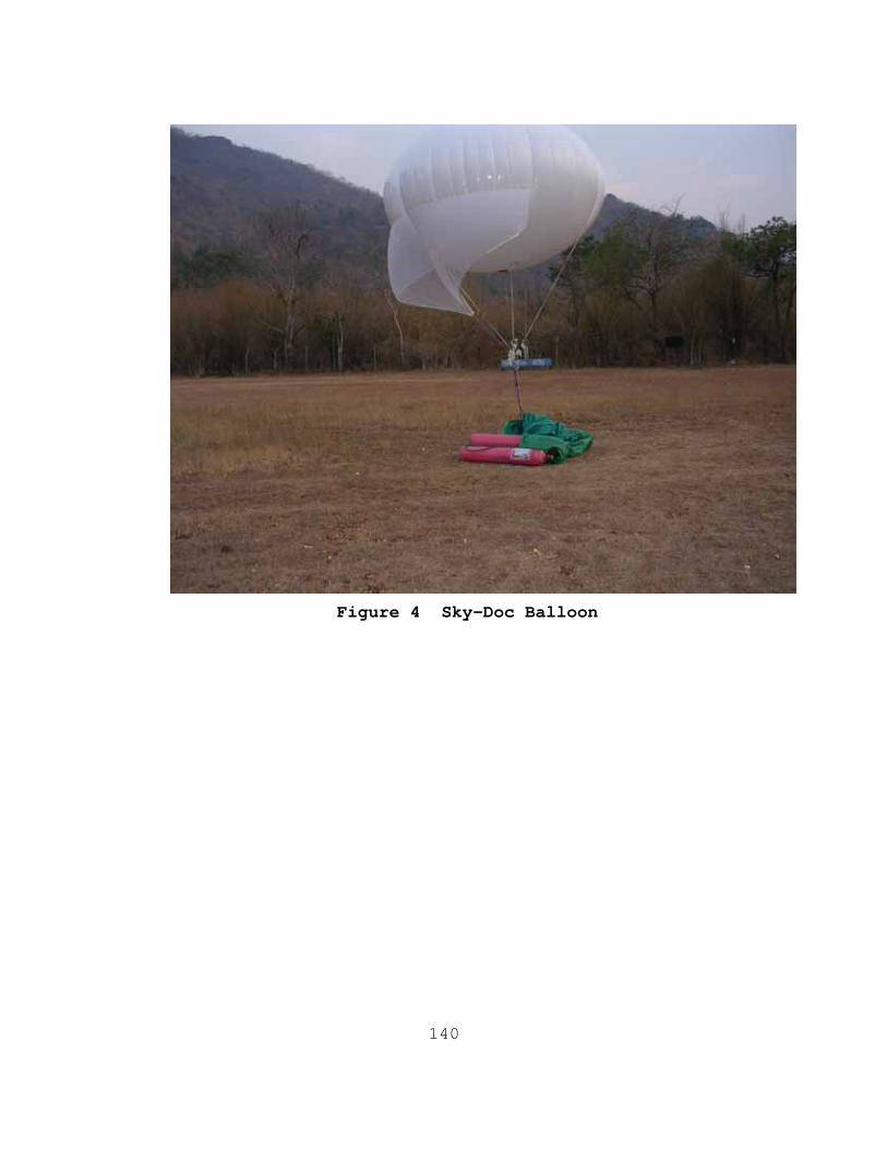
140
Figure 4 Sky-Doc Balloon
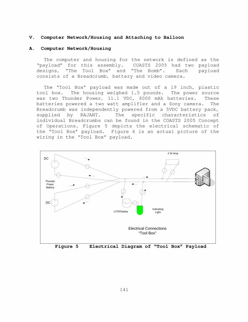
141
V. Computer Network/Housing and Attaching to Balloon A. Computer Network/Housing The computer and housing for the network is defined as the
“payload” for this assembly. COASTS 2005 had two payload designs, “The Tool Box” and “The Bomb”. Each payload consists of a Breadcrumb, battery and video camera.
The “Tool Box” payload was made out of a 19 inch, plastic
tool box. The housing weighed 1.5 pounds. The power source was two Thunder Power, 11.1 VDC, 8000 mAh batteries. These batteries powered a two watt amplifier and a Sony camera. The Breadcrumb was independently powered from a 5VDC battery pack, supplied by RAJANT. The specific characteristics of individual Breadcrumbs can be found in the COASTS 2005 Concept of Operations. Figure 5 depicts the electrical schematic of the “Tool Box” payload. Figure 6 is an actual picture of the wiring in the “Tool Box” payload.
DC
DC
2 W Amp
IndicatingLightLCD\Display
ThunderPowerBattery
Electrical Connections “Tool Box”
Figure 5 Electrical Diagram of “Tool Box” Payload
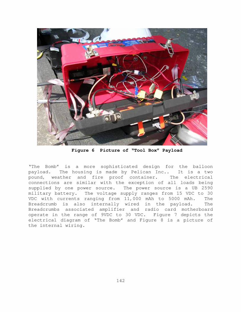
142
Figure 6 Picture of “Tool Box” Payload “The Bomb” is a more sophisticated design for the balloon payload. The housing is made by Pelican Inc.. It is a two pound, weather and fire proof container. The electrical connections are similar with the exception of all loads being supplied by one power source. The power source is a UB 2590 military battery. The voltage supply ranges from 15 VDC to 30 VDC with currents ranging from 11,000 mAh to 5000 mAh. The Breadcrumb is also internally wired in the payload. The Breadcrumbs associated amplifier and radio card motherboard operate in the range of 9VDC to 30 VDC. Figure 7 depicts the electrical diagram of “The Bomb” and Figure 8 is a picture of the internal wiring.
143
Figure 7 Electrical Diagram of “The Bomb”
Figure 8 Electrical Wiring of “The Bomb”
Figures 5 and 6 show simple schematics of each payload. The batteries are connected in parallel to supply 11 to 15 VDC to the payload. All loads are connected in parallel to the main
144
line. When in parallel, each load will receive the same voltage and draw current as needed to operate. A couple of voltage regulators were used to limit the 15 VDC supplied from the UB 2590 to 11 VDC loads. “The Bomb” was better suited and had a smaller wind profile than “Tool Box”. “The Bomb” was more compact and weighed five pounds lighter than the original payload. This design also used a small CPU fan to induce some air flow within the payload housing. This minimized the temperature which was also aided through using a light color for the housing. Equipment to create “The Bomb”:
• XL Breadcrumb motherboard and amplifier • 36 inches of red 22 gauge wire • 36 inches of black 22 gauge wire • Eight 22 gauge wire connectors • One UB 2590 Battery • One 12VDC CPU fan • One Pelican case (12”X9”X5”) • One DC manual switch • One 12VDC LED • One Voltage display LCD • Two Voltage regulators (15 VDC- 10VDC)
Breadcrumb Connections
The XL Breadcrumb houses an Ethernet connection for attaching IP enabled media (laptops, cameras). The Breadcrumb is also equipped with an internal and external antenna connection.
B. Attaching the payload to the balloon.
The payload should be powered down prior to attaching to the balloon assembly. This ensures that the payload will be operational for up 10 hours when deployed with the balloon. The following steps will guide the operator to successfully
deploy the payload and place the network in operation. 1. On the top of the payload, turn the “ON-OFF” switch to “ON”. This can be monitored by noting the digital voltage

145
display reads the rated voltage (Approximately 15 volts when the UB 2590 is fully charged) and by the indication light. 2. The payload should be fully assembled with the Camera connected to the Ethernet connection on the Breadcrumb. Ensure that all antennas are attached. 3. The payload has four pad-eye screws to attach it to the balloon. Use a two-three foot strap (rated for 20 to 30 pounds of weight) and strap the payload to the mounts on the balloon.
4. Once the payload is attached, slowly deploy the balloon. (Section III. A.)

146
THIS PAGE INTENTIONALLY LEFT BLANK
147
APPENDIX C. COASTS 2005 AFTER ACTION REPORT
Coalition Operating Area Surveillance and Targeting System
28 July 2005
From: Jim Ehlert, Naval Postgraduate School
To: Information Sciences Department, Naval Postgraduate School
Subj: AFTER ACTION REPORT FOR COASTS 2005, MAY 06-21
Ref: (a) Concept of Operations (dated 15 March 2005)
Operations Order 02-05 (Thailand Rehearsal)
Operations Order 04-05 (Thailand Demonstration)
COASTS 2005 March After-Action Report (dated 21 April 2005)
Encl: (1) Personnel Roster
(2) After Action Report 802.11/802.16
(3) After Action Report Balloon
(4) After Action Report UAV
(5) COASTS 2006 Initial Concept Timeline and Recommendations
1. Background. The COASTS program is a joint project between the NPS and the Royal Thai Armed Forces. The COASTS program is interested in researching low-cost, state-of-the-art, rapidly scaleable airborne and ground communications equipment suites including various wireless network technologies. Along with the organizations mentioned above, numerous commercial vendors participated in the program such as Mercury Data Systems, Cisco Systems, CyberDefense UAV, Inter-4, Rajant Corporation, and Redline Communications.
148
(a) Airborne Wireless Access Points
Employing a stationary, lighter-than-air vehicle equipped with a wireless access point is perhaps well suited to extend the effective wireless network range and user connectivity. For example, a helium filled, tethered balloon offers the advantage of a line of sight (LOS), over the horizon (OTH), Wi-Fi relay platform. This same balloon can be outfitted with various antennas and amplifiers enabling the free-flow of viable information to and from the on-scene commander who may be positioned to support other assets miles away.
In fact, helium balloons offer an inexpensive solution to maintaining the visual, audio, and sensory information required to conduct operations. These balloons can be deployed within minutes and maneuvered into a position (altitude) several thousand feet in the air with a minimum radar cross section (RCS) and at an altitude safe from light arms fire. Equipped with an antenna, and the appropriate RF hardware, ground-based users can access the local tactical network through the balloon and receive real-time information while performing their mission. The variety of information transferred is limited to the 802.11 bandwidth and the software capabilities of the individual units.
Peacekeeping, law enforcement, and first-responder personnel are frequently called upon to enter physical environments that adversely affect, or limit, the capabilities of current communication tools. Combining an all-weather balloon, equipped with Wi-Fi technology, and multiple ground Wi-Fi units, offers almost instant situational awareness and communications over any land or water mass. This connectivity can reduce response times and tactical decisions and thereby create advantages for the on-scene commander.
(b). COASTS Field Experimentation
During a field experiment conducted in Lop Buri, Thailand during May 2005, the COASTS team successfully integrated Unmanned Aerial Vehicles, aerial balloons, portable and fixed ground-based sensors, Global Positioning System (GPS) and non-GPS enabled tracking systems, as well as other technologies to provide shared situational awareness to local and strategic users. This demonstration focused on integrating all of the sensor data at a Royal Thai Army command and control vehicle, called a Mobile Command Platform (MCP), and then linking it to
149
higher headquarters, specifically the Royal Thai Air Force Headquarters (RTAF HQ) and the Royal Thai Supreme Command (RTSC), both located at different compounds in Bangkok, Thailand.
2. Mission. In conjunction with the Royal Thai Armed Forces (RTARF), the COASTS team conducted an operational rehearsal of the COASTS network topology in the Wing 2 (Lop Buri) training area of Thailand from 06-21 MAY 2005. Further details on operational issues can be found in the Operations Orders 02-05 and 04-05 (ref b and c).
3. Personnel. The COASTS team consisted of four faculty and eleven students from the Naval Postgraduate School. Most of the students were able to conduct thesis research within the scope of the demonstration network. Several civilians representing private companies were also present. Their role was to assist in implementing some of the cutting edge technologies that COASTS employs to create the network. See Encl (1) for a detailed roster of the team.
4. Operations.
(a). Scheme of Maneuver
Per the previous deployment to Thailand in March 2005, a field research exercise and demonstration was conducted in an iterative manner. Building on the detailed field rehearsals which were conducted at Ft. Ord, CA in February of 2005 and the March deployment to Thailand, the network was re-established in Lop Buri. As in March, this evolution was completed in four phases:
• Preparation
• Network set-up
• Network integration
• Recovery.
150
For this deployment, the preparation phase also included the evaluation period from the March lessons learned.
(b). Preparation Phase
The team was initially formed in January of 2005; several organizational, planning, and equipment purchasing issues were resolved during this phase. As some equipment did not arrive until after the February rehearsal, there was no opportunity to properly test and integrate those technologies into the network during the initial experimentation phase. The NPS acquisition staff did an outstanding job in responding very rapidly to purchase order requests; however, due to the cutting edge nature of this project, and the team’s unfamiliarity with many of the technologies and equipment requirements, many items were not identified until very late in the preparation phase. There was a steep learning curve, but all parties persevered and ultimately acquired all necessary equipment for the deployment.
Detailed coordination with our Thai counterparts was difficult. This was primarily due to the fact that assignments within the RTARF were not clear until the team’s arrival in country. The team deployed to Thailand with several important technical questions, relating the topology, not answered.
The redeployment to Thailand in May involved many of the same difficulties from the March deployment, as well as some new ones. Most significant of the new problems were the loss of key personnel, and the sudden addition of certain new team members. Both the student team leader and the network lead left COASTS immediately after the return from the March rehearsal. The addition of four new personnel to the COASTS May deployment team also increased the difficulty level of integrating a functional team for demonstration.
(c). Network Set-up Phase
This phase was difficult yet successful. The ambitious goal was to arrive in Thailand with all coordination and knowledge needed to integrate with RTARF and successfully build the network in short order; in reality, the advanced party’s detailed site coordination visit was being completed even as the main team members arrived in country.
Many important technical questions were not answered until COASTS team members physically arrived at their operating locations around Thailand. The team was able to rapidly assess
151
the situation on the ground and react accordingly to construct the network. The COASTS team was undermanned and strained; especially when operations required team members to be spread across multiple sites. The civilian vendor representatives played a critical role in filling gaps in the need for additional personnel.
The majority of the problems identified during and after the March rehearsal were handled by the advanced party for the May demonstration, which was deployed to Thailand one week before the departure of the main body. With a combined two-person team, many of the identified problems were able to be completed prior to main body arrival. Considerable network set-up, logistical management, and site survey re-verifications were accomplished during this lead time.
(d). Network Integration Phase
The biggest challenge during this phase was establishing the links between Wing 2 and the RTAF headquarters. The COASTS team brought several Cisco routers to Thailand in order to make this happen. The team worked side by side with the Thai communications staff at their network facilities to install and configure the routers. Much troubleshooting and network experience was required to make the links work, but all links were up and tested by Monday of the second week.
Another challenge, during network integration, was implementing various bandwidth enhancements. These enhancements were devised after learning the network’s limitations during the March evolution. One of these enhancements, implementing multicast, proved to be easy to configure. Multicasting was difficult to operate smoothly and the quality of multicast streaming video was very low. This caused the team to revert to less efficient unicast video streaming.
The other attempted measure was to combine the bandwidth of the two main links between Lop Buri and Bangkok. One link was a T1 (Bangkok) and the other was an E1 (Lop Buri). Overcoming the bandwidth limitations between the two data pipes turned out to be too difficult. This problem was put aside in the pursuit of other goals.
Network integration was more difficult on the May deployment. Given the close timing of the two COASTS 2005 evolutions, a number of desired trouble-shooting efforts were not able to progress sufficiently in time for the May
152
demonstration. The foremost issue, seen during the March deployment, was significant 802.11b connection problems.
This issue necessitated the use of spectrum analyzers in the field to narrow the trouble-shooting process. The suspected conflict was signal interference between the air field assets and the COASTS 802.11b equipment. There was not enough time to obtain the necessary equipment and train operators to perform a usable RF spectrum evaluation. This particular need, as well as a host of other needs expressed in reports attached below and within the team’s corporate knowledge, will be considered in planning the site survey and coordination trips prior to the first COASTS 2006 rehearsal trip.
Ultimately, the team performed a successful demonstration, even given the setbacks in network setup and loss of aerial assets.
(e). Recovery Phase
A coalition debrief was conducted after the operation. Good feedback and lessons learned were exchanged from both sides. In addition, a draft timeline and schedule were discussed for COASTS 2006. This dialogue will prove to aid in the planning and preparation for the next deployment.
The recovery phase of the May evolution had smooth elements, which were based on experiences from the March deployment. Once again, the importance of Equipment Density Lists (EDLs) for each node was realized as a key component of the 2006 deployment. Inventorying equipment in the recovery phase was time-consuming, but with the focus of packing based on accuracy, time was not factored into the paperwork.
While the gathering and inventorying of equipment was handled properly, the packing and embarkation lacked proper attention to detail. Further care should have been taken to ensure an even weight distribution across all shipping containers, considering the high cost of transporting overweight luggage on commercial carriers. The return trip from Thailand cost over $1300 (US) in oversized baggage fees.
(f). Safety
A safety officer was appointed and an operational risk assessment was conducted. There were no major safety incidents during the trip. However, there was some unsafe activity in installing 802.16 antennas on the radio tower at Lop Buri. The
153
surrounding environment required the antenna to be placed on the tower over 60 feet. The COASTS team did not have the proper safety equipment and had to improvise. Some safety equipment and harnesses were procured on the spot. Overall, this climbing requirement was not identified early and was a potential hazard.
The safety hazards to the climbing team at the 802.16 node were addressed through the addition of safety gear, and the focus on the usage of professional Thai climbers. No new safety hazards were experienced during the May 2005 exercise.
One safety oversight did occur since emergency cards were not distributed to the May team. Although no injury resulted, it is an important oversight to note to prevent future omissions.
5. Logistics.
(a). Embarkation
The basic embarkation plan was to shuttle the equipment in standard size Pelican cases. These cases were checked as luggage aboard commercial air. Several oversized items were shipped via FedEx to JUSMAGTHAI via our US Embassy point of contact. All items shipped FedEx were shipped prior to the team’s departure, and arrived in country within days. However, it still took up to three weeks for the items to clear Thai customs. Overall, the embarkation plan worked and there were no issues.
New shipments for the May demonstration all arrived on time and none were held by customs. More equipment was brought to Thailand by the main body.
(b). Equipment
Much of the equipment for COASTS was either borrowed from civilian companies through CRADAs, or was procured by the team. Purchase orders (POs) were the vehicle to buy equipment. While students are generally the individuals who identify requirements and draft POs, tight control must be kept on the process. Students that have a need to call vendors directly in planning a purchase order must be briefed on applicable rules and procedures before doing so. The staff at NPS dealing with POs was very supportive of the COASTS project and understood the reason for late requirements and the need for quick action.
154
(c). Transportation
A majority of the ground transportation in Thailand was provided by the Royal Thai Air Force. A 45 passenger bus was put in direct support of the team for a majority of the trip. This oversized bus was needed due to the amount of equipment. In addition, several civilians were accommodated in the interests of mission support. At Lop Buri, several vans were contracted for the team. These proved critical in making numerous logistical runs around the Lop Buri area. Organic transportation was necessary for the success of the mission. In both deployments, only one incidence of miss-management occurred. At the end of the March deployment, the return bus to the airport did not arrive prior to the team departure. This incident was minor and easily addressed by the use of the local taxi service.
(d). Gear Storage
The Royal Thai Air Force provided short term storage for much of our equipment that will be used during the May deployment. The equipment was stored at the Search and Rescue Squadron Facility in Lop Buri. Long-term storage was also managed by the Royal Thai Air Force at Wing Two in Lop Buri. All equipment was accounted for with no losses.
6. Communications
(a). Communications Links
(1). 802.11.
802.11b was the backbone of the wireless mesh in Lop Buri. In the March rehearsal, the team did not have a dedicated individual managing these links to ensure success. As a result, some antennas were not located properly and optimum performance of the 802.11 network was not accomplished at Lop Buri. Time constraints limited detailed troubleshooting. One possible reason for poor 802.11 performance, could have been other antennas and interfering RF energy around the tower facility.
The May team attempted to compensate for the lack of a dedicated 802.11 manager by assigning the duty to one node leader. The use of the 802.11 across many different nodes is too big for one person to control the trouble-shooting process in
155
the field. COASTS 2006 will assign at least 3 individuals knowledgeable of 802.11 and antenna deployment to broaden trouble-shooting efforts.
The breadcrumbs were strongly affected by weather and distance; they were not able to be deployed as advertised by contractor specifications. The lack of fans, a heat sink, and a vent in plastic cases caused the equipment to overheat on a regular basis. The network placement of these breadcrumbs had to be adjusted considerably from our original intention of a long-distance surveillance network.
Different 802.11 equipment needs to be integrated into future COASTS 2006 deployments in order to extend the desired range of the wireless network cloud. The environmental factors were too much of an effect on the Rajant breadcrumb for it to be utilized by design. A more resilient model will be required before this technology can be considered tactically effective. See enclosures 4 -7 for more technical descriptions of the 802.11 network deployment and future recommendations for deployment.
(2). 802.16
802.16 links worked very well. Once established, these links supplied data rates upto 54MBps. The main issues were found in set-up, particularly when creating the shot between Lop Buri and Wing 2.
Upon the return to Thailand in May, the ADVON party inventoried the 802.16 equipment, and surveyed the downtown communications facility, and the placement of that antenna. During the first day of operations, one of the AN-50s experienced a power surge, making the unit inoperable. Re-setting the fuses did not correct the problem, highlighting the seriousness of the damage form the surge.
The 802.16 links were re-established in little time. See enclosures 4 -7 for more technical descriptions of the 802.16 OFDM link deployments.
(3). T-1 from Wing 2 to RTAF
This link was difficult to establish because several routers had to be installed. This requirement was identified on the fly and the Thais had to locate the appropriate personnel to execute the appropriate changes.
156
Considerable time was used by the ADVON party and the May main deployment body to achieve the establishment of the T-1 link. The T-1 became the primary demonstration link, but multicast and load-balancing was never achieved during the tests.
(4). E-1 from Lop Buri
No significant problems with this link were observed.
(5). E-1 from RTAF to RTSC
This link was tough to establish. The primary reason for this was the fact that the link at the Royal Thai Supreme Command (RTSC) was routed to a conference room, not an established command center. Again, the network engineering experience on the team made the link successful.
(6). Satellite Communication Link
This link was made by a civilian company. It was not operational until late on the last day of operations. For this reason, we were unable to integrate it and pass traffic across the link.
Various planning was put into place to establish the Satellite network for the demonstration. Unfortunately, the cost of the usage of the satellite network made it impossible to afford the satellite connection for more than one day. The day of the demonstration was not enough time to properly integrate the satellite into the network properly. Further expansion of this satellite technology is planned for the COASTS 2006 deployment.
(b). Network
(1). Track Point
The software integration worked as advertised and met the stated requirements for the exercise. Using the software, members from the Royal Thai Armed Forces were able to monitor the situation in Lop Buri and control cameras from their command post in Bangkok.
Track Point was functional for the May 2005 demonstration but significant set-up obstacles were necessary to overcome in
157
accomplishing its implementation. The major contributing factors hindering a smooth and successful integration was the lack of a stable 802.11 network, changes in Areas of Operations, and key personnel tasked with maintaining network connectivity and troubleshooting. The sensor inputs and network performance functionality of TrakPoint are dependant on a stable network for integration, management, and event population. With the difficulties in establishing a functional mesh, troubleshooting and optimization schedules were shortened creating a significant lag in effective implementation. From these lessons learned, a major developmental change has taken place to correct the architecture to a Publish/Subscribe system. This will negate the issues resulting in a lack of performance of the TrakPoint application in COASTS 2005. Increased training by all 2006 team members, as well as the addition of a student software liaison between NPS and MDS, will be initiated to compensate for user end problems. Greater coordination will provide for greater success for Track Point.
(2). Router Configuration
All network requirements and router configurations were eventually identified and installed. The success in these links made the topology possible. Several key individuals had extensive networking knowledge that was critical. Detailed experience in these skill sets is a must for future missions.
(c). Sensors
(1). Cameras
The Sony camera worked well and as designed. However, it did not work well on the balloon platform. The balloon, even in light wind conditions, was too jerky and did not provide a stable enough platform for the camera. It must be noted that the primary purpose for the balloon is to act as a breadcrumb 802.11 node, not a camera platform.
In May, more cameras were implemented into the network to fulfill various sensor requirements. The number of cameras used necessitated a camera node manager to be created in-country. This task fell on the 802.11 node manager, who was already over-worked concerning breadcrumb issues. All cameras operated well, although with the increase in cameras, the importance of compression software for the network became apparent.
158
In 2006, cameras will be included in the planned cross-training between all deploying COASTS team members, and will become the overall responsibility of the Sensor node leader.
(2). Crossbow Sensor
This device was not able to be implemented. The problem was diagnosed as software related. With insufficient manpower and resources, a decision was made not to continue troubleshooting, but rather make a site visit to the vendor upon return to the United States. The Crossbow Company is located within 60 miles of the Naval Postgraduate School.
Before the return to May, LT Cone and Mike Clement traveled to Crossbow in order to improve their training concerning the implementation of the sensors into the network correctly. Further training enabled a successful set-up for the demonstration in May.
The Crossbow suite will be replaced by the MDS deployable sensor suite in the next COASTS 2006 deployment.
(3). Unmanned Aerial Vehicle (UAV)
The UAV’s performance in the May 2005 demonstration was poor at best. Although the network camera was able to integrate into the network, the UAV itself was unable to maintain a flight status long enough to be integrated during the exercise. The swirling Lop Buri winds were to strong for the UAV operator to compensate for, resulting in a very early mission-ending crash. A re-designed UAV is planned for integration into the COASTS 2006 deployments.
7. Host Nation Support. Other than pre-deployment planning at the action officer level, host nation support was excellent. All requests for equipment and support were met. In addition, ad hoc and unanticipated support requests were also handled very quickly and efficiently. The professionalism and hospitality of the Thai military was noteworthy and a positive experience for all involved.
8. Aviation Operations. The team appointed an Air Marshall to conduct all aviation planning and coordination. This proved invaluable as there were many aviation issues to be addressed. Prior to arrival in Thailand, several aviation information items
159
were unknown. Many of these issues were sorted out during a confirmation brief upon arrival. Planned daily air meetings were rolled into a group meeting for the day.
The aviation meeting should be separate in the future. Several air assets were not able to support the operation due to real world requirements. This turned out to be good as network set-up took longer than expected. Several important flights were made with the AU-23. Connectivity to the 802.11 network during these flights was marginal. However, these initial flights have allowed for some detailed troubleshooting to begin.
In the May 2005 demonstration, the Air Marshal was unable to join the team until exercises were underway for almost four days. This placed training of a deputy Air Marshal at the forefront of deployment training. LT Lee, as the balloon operator, was the most logical to fulfill this role, and accomplished all required tasks with no incidents.
9. Future Operations. Planning for COASTS 2006 is underway at this time. The point of contact on this matter is Mr. James Ehlert who can be reached at 831-656-3002.
MR. JAMES EHLERT
Project Lead
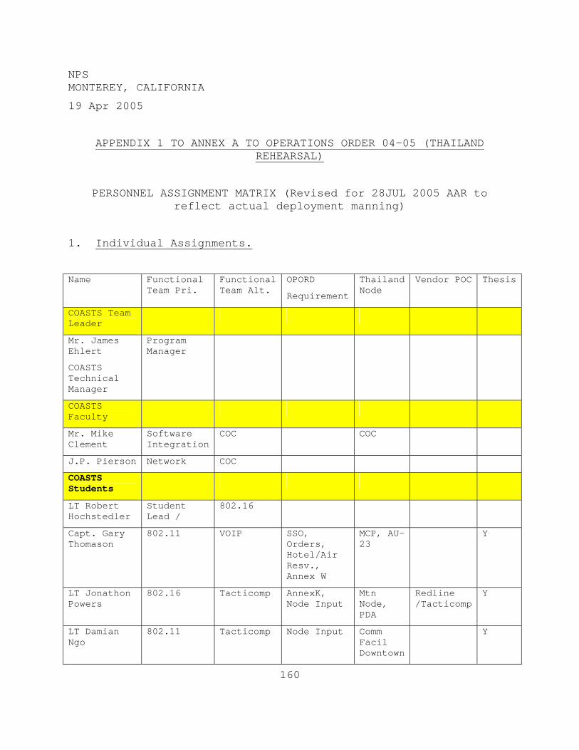
160
NPS MONTEREY, CALIFORNIA
19 Apr 2005
APPENDIX 1 TO ANNEX A TO OPERATIONS ORDER 04-05 (THAILAND REHEARSAL)
PERSONNEL ASSIGNMENT MATRIX (Revised for 28JUL 2005 AAR to reflect actual deployment manning)
1. Individual Assignments.
Name Functional Team Pri.
Functional Team Alt.
OPORD
Requirement
Thailand Node
Vendor POC Thesis
COASTS Team Leader
Mr. James Ehlert
COASTS Technical Manager
Program Manager
COASTS Faculty
Mr. Mike Clement
Software Integration
COC COC
J.P. Pierson Network COC
COASTS Students
LT Robert Hochstedler
Student Lead /
802.16
Capt. Gary Thomason
802.11 VOIP SSO, Orders, Hotel/Air Resv., Annex W
MCP, AU-23
Y
LT Jonathon Powers
802.16 Tacticomp AnnexK, Node Input
Mtn Node, PDA
Redline /Tacticomp
Y
LT Damian Ngo
802.11 Tacticomp Node Input Comm Facil Downtown
Y
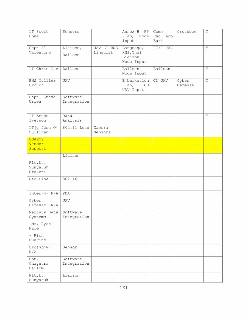
161
LT Scott Cone
Sensors Annex B, FP Plan, Node Input
Comm Fac. Lop Buri
Crossbow Y
Capt Al Valentine
Liaison,
Balloon
UAV / HNS Linguist
Language, HNS,Thai Liaison, Node Input
RTAF UAV Y
LT Chris Lee Balloon Balloon Node Input
Balloon Y
ENS Collier Crouch
UAV Embarkation Plan, CD UAV Input
CD UAV Cyber Defense
Y
Capt. Steve Urrea
Software Integration
LT Bruce Iverson
Data Analysis
Y
LTjg Josh O’ Sullivan
802.11 Lead Camera Sensors
COASTS Vendor Support
Flt.Lt. Sunyaruk Prasert
Liaison
Red Line
802.16
Inter-4- N/A PDA
Cyber Defense- N/A
UAV
Mercury Data Systems
-Mr. Ryan Hale
- Rich Guarino
Software Integration
Crossbow- N/A
Sensor
Cpt. Chayutra Pailom
Software Integration
Flt.Lt. Sunyaruk
Liaison

162
Prasert
Rajant Corporation- N/A
802.11
163
After Action Report
COASTS 2005
802.16/802.11 Network
Review of Networking Goals:
• Create 802.11b network to process and distribute digital data including:
o video streaming
o text
o sensory information
o audio
• Establish Long-haul 802.16 links between Wing 2 Air Tower, the Lop Buri Downtown Communications Building and the Mountain Communications Facility.
• Obtain 11 Mbps connectivity with all nodes within the 802.11b mesh network
• Obtain 54 Mbps connectivity through 802.16 links
• Provide real-time data to client links (Tacticomps and laptops) through mesh network
• Provide real-time response tools implementing Trak Point Software.
• Integrate 802.11, 802.16, 802.3 protocols to establish continuous real-time data to forward deployed units and remote Command and Control centers. (RTAF and RTSC)
164
Goals Attained:
• 802.11b network established
• 802.16 links established
• Real-time data reached every node in the network
• Trak Point software implemented
• Integration of various protocols achieved
• Obtaining a 802.16 link connectivity of 54 Mbps.
Lessons Learned:
• For several months we made numerous requests for information about the location, and accessibility of the antenna mast located at Downtown Lop Buri and at the Mountain Comm Facility. Despite repeated requests and several assurances that we would receive this information we remained in the dark until the day of installation. This lack of response to our RFIs directly impacted our operations at Lop Buri Wednesday and Thursday.
• The two days spent at Wing 6 at the Air Field allowed for consolidation of all the equipment shipped in early February and shipped out in advance through Federal Express. All the equipment was accounted for, packed for operational use, and staged for operations. This set-up allowed for laying out the gear in a centralized area facilitating personal interaction and rapid coordination for troubleshooting and systems configuration.
• Automated network management tools that are SNMP enabled might allow for greater network awareness, yet limit the impact on node operators. Recommend looking into software that will pull some of this information from system devices. If manning constraints can support a recommend one person be designated Network Operations Chief as a sole assignment.
165
• The installation of this 802.16 link represented a significant investment in personnel, time, and resources. The resources required during this installation set us back in terms of set-up, and operations conducted at Wing 2 and at RTAF/RTSC. Key personnel (Ryan Hale, JP Pierson, Rob Hochstedler, Andy Eu, and Brian Steckler) were tied up for two days at this site. Prior site survey would have discovered that the antenna mast would need to be scaled, to a height of at least 150 feet, requiring, safety harness, rope and pulley system, gloves and a ladder just to access the structure. Aspects that could have been mitigated through a site survey stole away personnel for a significant amount of time because answers we sought were not provided and because the site was not previously reconnoitered.
• Ensure teams of two (at a minimum are deployed to set-up 802.16 links in the future. Apply lessons learned from this installation to better prepare for future 802.16 installations in the future. Had this team had access to the laptop running Redline Communications RF Monitor application and access to the AN-50 Graphical User Interface (GUI) the full 54Mbps would have been attained.
• The purchase of these antenna masts will make it possible to set up 802.16 antennas in any location independent of an existing antenna mast or man-made structure. Research and procure two 28 foot collapsible antenna masts to raise 802.16 antennas.
• Throughout the planning phase COASTS 2005 was designed to incorporate the use of the Mobile Command Post (MCP). Days prior to our deployment we learned that we would lose the MCP due to real world requirements, but at the last minute we learned that the MCP would be made available for COASTS ’05 Phase II. Due to poor coordination between COASTS personnel and Thai military representatives this asset was not fully integrated. The MCP did not play a role in the May demonstration. The integration of high profile assets such as the MCP, need to be planned very early in the process.
• COASTS members and Thai counter parts must be involved in a site survey. Inputs from the Thai military
166
concerning terrain, landmarks and placement of network assets is insurmountable.
• Ensure sufficient time is allotted for gear accountability and configuration before any type of operation is planned. Conduct localized and full scale operations with all equipment similar to our efforts at Wing 6 flight line to ensure all essential equipment is accounted for, properly configured and ready for operations.
• Training on utilizing the RAJANT Breadcrumb must be given to all personnel involved in the operation. The 802.11b lead needs to be responsible for the procurement, inventory, and coordinating the deployment and retrieval of breadcrumbs, antennas, and other mesh network related equipment.
• The 802.11 lead should have a thorough knowledge in operating BCAdmin and the deployment concerns of the breadcrumbs. He also needs to be familiar with radio wave propagation and antennae patterns.
• Distance for SE, ME with 8 dBi omni-direction external antenna was limited to 300 meters with partial to full line of sight for 11 Mbps. The SE internal/ ME external 1 dBi antennas were limited to roughly 100 meters for a full 11 Mbps.
• The ideal configuration for the command center was to hardwire through an Ethernet cable to an XL with an external 8 dBi omni-directional external antenna. Co-located with an SE connected to an 18 dBi flat-panel external antenna, directed in the direction of a balloon or other large distance breadcrumbs.
• The battery life for all the breadcrumbs was limited to an operational optimal time of 6 hrs. Ideally in an operational environment, each breadcrumb that will be running on batteries should have two batteries.
• All RJ45 connections failed internally on ME breadcrumbs.
167
Recommendations:
• Points of contact and support personnel from the Thai Armed Forces need to be identified and assigned to the project much earlier in the process and through official tasking.
• For future deployment, recommend using SE for all Ethernet required connections, such as cameras, due to their reliable RJ45 interface and using ME for linking and redundant nodes, due to their dual external antennas.
• Ensure a site survey of all locations that will support network operations are inspected during site survey and planning conference meetings. Ensure proper personnel with technical expertise execute site surveys in order to properly assess the situation. Additionally, see item #2 above for assignment of Thai personnel to COASTS mission.
• All antennas need to be 6ft off the deck to get best signal propagation. The SE have internal antennas and also need to be located 6ft off the deck. The use of 7ft PVC pipes, procured locally, worked well.
• BCAdmin uses about 2 Mbps of network traffic per operating client. The number of clients running should be limited to provide more bandwidth.
• The Rajant breadcrumbs are not a reliable solution in this hostile environment. Rajant needs to research improving reliability in this kind of environment or COASTS needs to research replacing with a better breadcrumb.
• Change the color of the boxes (black is not a good color for heat)
• Increase internal air flow - add internal fan(s)
• Install heat sinks on some of the internal components
• Upgrade standard to 802.11g or 802.11n for better distance and speed.
• DLINK AP2100 Wireless Access Points were linked with 14.5 dBi Yagi Antennas with a nearly perfect point-to-
168
point bridge for providing constant and consistent T1 connectivity between the Wing 2 Comm Center and the Command Operations Center (COC). In the future, utilizing more of these WAPs for wireless links should be investigated. For example a point-to-point or point-to-multipoint bridge would have been a better choice than a breadcrumb for linking the firehouse to the network. The unreliability of a single bread crumb for a presentation link resulted in a number of connection problems during our local demonstration. The use of a DLINK WAP may have been a better alternative in connecting the COC to the mesh network as a more reliable connection.
• The payload (a modified XL) on the balloon and the COC XL needs to be tested operating together. The XL would consistently reset itself when trying to form a link with the balloon’s payload. This may have been a configuration issue with the way the two breadcrumbs establish their IP addresses, however, this was unable to be tested during this demonstration due to the unavailability of the balloon payload at the end of the deployment.
• Overall, the team did not have enough breadcrumbs to accomplish the intended mission. To properly employ the Rajant breadcrumbs in this hostile environment, it is very important to employ an overlapping, redundant mesh. Single breadcrumbs would work less reliable than two co-located breadcrumbs. In fact the team would have been unable to meet our network requirements if it had not been for the 4 breadcrumbs and cable connectors returned from the Phuket Tsunami Relief Area.
• The team deployed with a shortage in the number of connecting wires for external antennas to breadcrumbs, resulting in less than optimal network configurations. There were no ready repair connectors in case a cable was damaged and the inability to utilize all antennas due to a lack of connectors particularly N-type to N-type. Varying lengths of cable were limited and reduced the options for ideal antenna placement.
• Tracking names of the breadcrumbs was an issue. In the future the 802.11b lead should recommend changing the names of the breadcrumbs from numbers to words. For instance, change ME 03-245 to ME Yorktown and then
169
mark the name on the breadcrumb. A number of personnel had issues remembering the numbers on the breadcrumbs.
• Writing the deployment location and configuration on the breadcrumb prior to the operation helped in integrating network assets.
• If balloons are utilized in the future, they should contain two separate bread crumbs and more than one balloon should be used in a given footprint.
• To reduce the bandwidth constraints of cameras, the use of MPEG4 and multicast through a UDP protocol needs to be further tested and researched. This will eliminate the constraints of Motion JPG. For a future configuration, use MPEG4 for real-time monitoring and streaming to long distances and locally store Motion JPG to a server through the camera software for after action analysis.
• Before using cameras on the network, ensure all computers have been properly upgraded. To run MPEG4 streaming, the connecting computers require an upgrade to DirectX 9. Due to the undocumented requirement and lack of Internet access, multicasting was not fully tested.
• The Rajant Breadcrumbs, although advertised as a one-switch network solution, proved to be somewhat more difficult when forced to interoperate with an existing network topology. The primary difficulty introduced was the use of a 10.x.y.z/24 IP address space that was not DHCP-controlled by the Breadcrumbs. Though it can be strongly argued that the addressing scheme was not a significant issue in most cases, there were certain elements that had to be adjusted to accommodate the Breadcrumb design. Unfortunately, the Breadcrumb design elements that were affected by this scenario were undocumented for the end user (e.g. that the Breadcrumbs used 10.x.y.1/8 addresses, so external gateways cannot also use those addresses when the Breadcrumbs operate in Bridge mode), so without having Rajant representatives on-site, this difficulty would have been a much worse issue. This lack of documentation needs to be corrected before the next evolution, to avoid future problems.
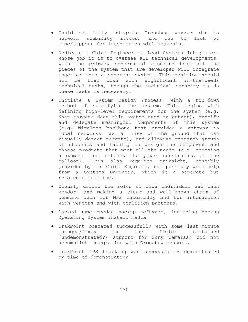
170
• Could not fully integrate Crossbow sensors due to network stability issues, and due to lack of time/support for integration with TrakPoint
• Dedicate a Chief Engineer or Lead Systems Integrator, whose job it is to oversee all technical developments, with the primary concern of ensuring that all the pieces of the system that are developed will integrate together into a coherent system. This position should not be tied down with significant in-the-weeds technical tasks, though the technical capacity to do these tasks is necessary.
• Initiate a System Design Process, with a top-down method of specifying the system. This begins with defining high-level requirements for the system (e.g. What targets does this system need to detect), specify and delegate meaningful components of this system (e.g. Wireless backbone that provides a gateway to local networks, aerial view of the ground that can visually detect targets), and allowing research groups of students and faculty to design the component and choose products that meet all the needs (e.g. choosing a camera that matches the power constraints of the balloon). This also requires oversight, possibly provided by the Chief Engineer, but possibly with help from a Systems Engineer, which is a separate but related discipline.
• Clearly define the roles of each individual and each vendor, and making a clear and well-known chain of command both for NPS internally and for interaction with vendors and with coalition partners.
• Lacked some needed backup software, including backup Operating System install media
• TrakPoint operated successfully with some last-minute changes/fixes in the field; contained (undemonstrated?) support for Sony Cameras; did not accomplish integration with Crossbow sensors.
• TrakPoint GPS tracking was successfully demonstrated by time of demonstration
171
After Action Report
COASTS 2005 Balloon Node
Review of Balloon Node Goals: • Use the balloon to create a center node for a mesh
network • Create a suitable video image from the balloon in order
to support a tactical picture of the environment. • Test the propagation paths of various antenna
configurations to test 802.11 signal strengths. • Establish power requirements for the balloon payload. • Determine environment limitations to equipment attach to
payload • Determine limitations of the balloon during operations in
designated areas. Goals Achieved:
• The balloon was successfully established as a center
piece for the breadcrumb mesh network. The maximum altitude was not achieved due to physical constraints and the lack of wind conditions or lack of signal strength from the host network to achieve the desired 2000 ft.
• Maximum continuous throughput achieved was ~ 2Mbps. The
most optimal antenna configuration seen during the demonstration was a horizontal and vertical dipole staged 90 degrees apart.
• Video image was established from the balloon and the
camera could be controlled via wireless interface. Camera control was established in Bangkok via 802.16 structure. Video imagery was not the primary mission of the balloon, however this imagery did give first hand analysis of the strength of the network.
• Power requirements for the particular payload was
determined. The batteries can last well over 8 hours with full operation of the camera from multiple sources over the network.

172
Lessons Learned: • Without wind, the Sky-Doc balloon only lifts 16.8 lbs • SkyDoc Balloons did not send a detailed operational guide
for the balloon. Specifics on the operation of the balloon will be included in the Operational Guide for the balloon node.
• The winch is only capable of holding 2000 ft of the 1000#
line. Smaller line might be used to extend operational characteristics of the balloon.
• The winch depletes a 12 VDC / 60 AH battery in ~4 hours
of use. • Continuous operations of the winch for more than 30
minutes will cause extreme heat conditions. These temperatures can be minimized with adequate air flow across the winch housing. Keep winch out of the high temperature and rain as much as possible.
• The Sony camera proved to be very durable. It
demonstrated survivability in extreme environmental conditions.
• The toolbox is not the most desirable platform to send in
the air due to its broad faces and terrible aero-dynamic features.
• The balloon should be launched in an area clear of
mountains or conditions that create swirling winds. • The maximum throughput achieved was 11 Mbps for <3
minutes. Found that the Breadcrumbs are susceptible to high temperature conditions and humidity. These devices need some sort of internal fan or environmental control when used in environments such as Thailand.
• Need at least 3 people staged at the balloon for
operations (changing the payload, filling the balloon, etc.)

173
• Winch can be adjusted to increase amount of line it can hold.
• Maintaining a stable image from the balloon is very
difficult at low altitudes. Need stability lines from the payload to the balloon tether. Simple adjustment creates significant stabilization. Storing the balloon in an uncontrolled environment (warehouse) causes the material of the balloon to become weak and brittle.
• The extreme heat (100+ F) and intense sunlight of Lop
Buri also caused some deterioration of balloon material. The valve connection lost its adhesiveness during operations which caused air to leak out of the balloon. Due to the location of the valve and unfamiliarity of proper position during operations, uncontrolled leakage of air occurred during balloon operations.
• Inadequate air pressure coupled with high wind conditions
(12 knots +) resulted in uncontrollable balloon flight characteristics (intense spirals and rapid side movements). These flight patterns resulted in significant occurrences of the balloon making contact with the ground and the local foliage that created numerous pin holes in the balloon material which intensified the loss of helium during balloon operations.
• The balloon was left over a two day period without
supervision. This resulted in an unobserved casualty to the balloon. The balloon was not repairable. A 6 to 7 foot gash was created in the balloon material along one of the seams. This failure was unforeseen and could have been due to extreme weather conditions or by human tampering. Cause is still unknown.
• The balloon payload consisted of a RAJANT Super Crumb
powered by a UBI 2590 15 Volt battery. The unit was cooled by an internal fan and a Pan-Zoom-Tilt (PZT) Camera was attached to the unit through an Ethernet connection. All loads were powered by the same source.
• Battery operation was observed to last well over 6 hours
with all loads operational. Due to the limited flight operations (loss of air), proper operation from the balloon payload was observed for a consistent period of

174
time on the first and second day of operations. The balloon payload provided connectivity within the local mesh, with limited wireless pipes (1 to 6 Mbps) to the remote network (Wing 2 Control Tower).
• Extreme winds and improper air pressure within the
balloon caused irregular flight patterns. These extreme turns and twists caused the battery source in the payload to come in contact with the sensitive computer parts which resulted in a failure to the motherboard housing and radio cards. After this day of experimentation, the super crumb failed to operate correctly and connectivity to the local mesh did not exist.
• Decision was made to attach an SE breadcrumb to the
payload for future operations. Data was only collected with an 8dbi dipole antenna attached to the balloon. Further experimentation with various antennas could not be performed due to the failure of the radio card housing.
• The balloon is ideally operated during moderate winds
below 10 knots. This is not an all weather balloon. Extreme heat and solar conditions causes some deterioration of balloon material. Winds greater than 10 knots must be in a consistent direction. With swirling winds, the kite flap causes the balloon to twist with the changing winds and if the winds exceed 10 knots violent swirls have been observed.
• The balloon winch operated successfully. During extreme
flight variations, the winch and line successfully maintained retrieval and deployment capability. The winch is slow at best during operation. Manual operation of the winch is suitable during modest winds, but is ill advised during winds that exceed 10 knots.
• Carabiners were more than adequate to connect the balloon
to tether. • For future use, a housing should be equipped for the
winch to protect it from rain and dust. The only requirement for the maintenance of the winch is to grease the internals after operation. Proper documentation on the type of grease was not provided by the manufacturer.

175
This will be resolved once INCONUS, and proper maintenance of the winch will occur for future operations.
Recommendations: • For future balloon operations, it is recommended to use a
simple 10 ft ball balloon. This balloon is rated with a 25 pound lift during any wind condition. The only flight pattern that should be observed is a side to side motion. With the smaller balloon, less helium is required and the cross section is much smaller. The price of the balloon is significantly less than the Sky Doc balloons ($500.00 vice $2000.00)
• A super crumb should be tested again as the payload on
the balloon. A multi-polar antenna should be used for radio signals. The existing battery power is sufficient for greater than 8 hours of operation.
• The balloon should always be filled with air when
conducting subsequent operations to ensure that the balloon is free of holes or other material damage that will cause leaks.
• Camera operation is still a luxury for the balloon
operation. The intent of the balloon payload is extend network connectivity over the horizon. Camera on the balloon should be used as a safety parameter to monitor areas directly under the balloon.
• The following items must be on hand for proper
maintenance and handling of the balloon: – Patch kit (sealant and adhesives) – Work Gloves – Electricians Kit – Various Antennas with adapters (SMA male, N male
connections) – 3 to 4 bottles of 290 cu ft helium – 12 VDC car battery – 500 to 1000lb tether (Spectra) – 3-4 Carabiners – Crescent wrench – Assorted Screwdrivers

176
– Hex Wrench set – 2 UBI 2590 military batteries with chargers. – 18 to 22 gauge wire – Electrical connectors (pin type) – Small fans (12VDC) for payload housing
177
After Action Report COASTS 2005 UAV Node
Goal:
• Demonstrate the capability of a man-portable mini-UAV as an integrated tactical collection platform for real-time intelligence, surveillance, and reconnaissance (ISR) at the squad level.
Goals achieved:
• UAV video-feed was integrated into the COASTS wireless network.
• Tests the metrological effects upon the operation of the Cyber Defense Cyberbug UAV.
Goals unattained:
• UAV was unable to maintain consistent flight in Lop Buri due to the combined density altitude.
• Daytime operations prevented the test of the IR camera on the UAV.
• The Integration of the UAV camera was not established via a direct link to the COASTS network. It was linked through a Cyberdefense proprietary laptop and fed through a video application to the COASTS network for display.
Lessons Learned:
• When deploying the UAV, the combined environmental effects on the density altitude at the launch location need to be reviewed prior to deployment. The Cyberbug operated optimally during tests in the United States. The temperature, pressure, and air density in Monterey, CA was not substantial enough to affect the location’s air density. In Thailand, these factors combined to create the effects of an elevation at Lop Buri of 8500 feet of elevation. This created an air density to thick for the UAV to maintain flight.
• The temperature effects upon the UAV itself need to be
considered. Heat strongly effects the electrical
178
components inside the UAV itself, degrading network connectivity, GPS, and computers during the pre-flight stage.
• A more powerful UAV engine is required to maintain flight in Thailand.
• More than one UAV should be carried in order to ensure redundancy.
• The Cyberbug UAV is a very stealthy platform when deployed. The gray-white color combination, small engine, and small overall sail area make the UAV very hard to detect in flight.
179
LIST OF REFERENCES
1. COASTS Thailand Demo (May 2005) Concept of Operations
2. Peikari, Cyrus, & Chuvakin, Anton. Security Warrior, First Edition. Sebastopol, CA: O’Reilly Media, Inc.
3. Gast, Matthew S. 802.11 Wireless Networks: The Definitive Guide. Sebastopol, CA: O’Reilly and Associates, Inc.
4. Sklar, Bernard. Digital Communications Fundamentals and Applications. Second Edition. Upper Saddle river, NJ: Prentice Hall PTR.
5. Haykin, S., Communication Systems, John Wiley & Sons, Inc., New York, 1983.
6. Millman, J., & Taub, H., Pulse, Digital, and Switching Waveforms, McGraw-Hill Book Company, New York, 1965.
7. Benedetto, S., Biglieri, E., & Castellani, V., Digital Transmission Theory, Prentice Hall, 1987.
8. Ziemer, R.E., & Peterson, R.L., Digital Communications and Spread Spectrum Systems, Macmillan Publishing Company, Inc., New York, 1985.
9. Panter, P.F., Communication Systems and Design: Line-of-Sight and Tropo-Scatter Systems, R.E. Krieger Publishing Co, Inc., Melbourne, Fla., 1982.
10. Desoer, C.A., & Kuh, E.S., Basic Circuit Theory, McGraw-Hill Book Company, New York, 1969.
11. Friis, H.T., “Noise Figure of Radio Receivers,” Proc. IRE, July 1944, pp. 419-422.
12. Spilker, J.J., Digital Communications by Satellite, Prentice-Hall, Inc., Englewood Cliffs, N.J., 1977.
13. Shannon, C.E., “A Mathematical Theory of Communication,” Bell Syst. Tech J., Vol. 27,1948, pp.379-423, 623-656.
14. Solari, S., Digital Video and Audio Compression, McGraw-Hill, New York, 1997.
180
15. Rzeszewski, T., Digital Video: Concepts and Applications Across Industries, IEEE Press, 1995.
16. Stallings, W., Cryptography and Network Security, Second Edition, Prentice Hall, Upper Saddle River, NJ. 1998.
17. Grabowski, R., The Illustrated AutoCAD 2000, Autodesk Press, Canada, 2000.
18. Pfeiffer, W.S., Technical Writing: A Practical Approach, Third Edition, Prentice Hall, Upper Saddle River, NJ, 1997.
19. Skolnik, M.I., Introduction to Radar Systems, Third Edition, McGraw-Hill, New York, 2001.
20. Knott, E.F., “Radar Cross Section.” In Radar Handbook (ed. M. Skolnik), New York, McGraw-Hill, 1990, Chap. 11.
21. Bookner, E. Aspects of Modern Radar, Norwood, MA: Artech House, 1988, pp. 25-28.
22. Williams, P.D.L. “Limitations of Radar Techniques for the Detection of Small Surface Targets in Clutter.” The Radio and Electronic Engineer 45 (August 1975), pp. 379-389.
23. Day, J.P., & Trolese, L.G. “Propogation of Short Radio Waves Over Desert Terrain.” Proc. IRE 38 (February 1950), pp. 165-175.
24. Terman, F. Radio Engineering. New York: McGraw-Hill, 1937, Sec. 70.
25. DuBroff, R.E., Marshall S.V., & Skitek, G.G., Electromagnetic Concepts and Applications, 4th ed., Prentice Hall, Upper Saddle River, NJ, 1996.
26. Balanis, C.A., Antenna Theory: Analysis and Design, Harper & Row, New York, 1982.
27. Kraus, J.D., Antennas, 2nd ed., McGraw-Hill, New York, 1988.
28. Rappaport, T.S., Wireless Communications: Principles and Practice, Prentice Hall, Upper Saddle River, NJ, 1996.
181
29. Stuber, G., Principles of Mobile Communications, Kluwer Academic Publishers, Boston, 1996.
30. Stutzman, W.L., & Thiele, G.A, Antenna Theory and Design, Second Edition, John Wiley & Sons, Inc., New York, 1998.
31. Rowels, S., & Ghahramani, Z., Learning Nonlinear Dynamics Using the Expectation-Maximization Algorithm, Gatsby Computational Neuroscience Unit, University College London, Alexandra House, London WC1N 3AR, UK: 2005.
32. Maxey, M.R., & Riley J.J., “Equation of motion for a small rigid sphere in a nonuniform flow.” Physics of Fluids, Vol. 26, Issue 4, pp. 883-889, April 1983.
33. National Scientific Balloon Facility, Scientific Balloons, Internet article. December 2004. www.nsbf.nasa.gov/balloons.html March 2005
34. Personal interview with Michael Clement, Network Engineer COASTS 2005. March 2005.
35. Hyperlink Technology Antenna, Omni-directional and Yagi Specifications, Internet. www.hyperlink.com May 2005.
36. Wi-Fi Plus, Inc. Multi-polar Antenna Specifications, Internet. www.wifi-plus.com May 2005.

182
THIS PAGE INTENTIONALLY LEFT BLANK

183
INITIAL DISTRIBUTION LIST
1. James F. Ehlert Naval Postgraduate School Monterey, CA
2. Brian Steckler Naval Postgraduate School Monterey, CA
3. Dan Boger Naval Postgraduate School Monterey, CA
3. U.S. Pacific Command (USPACOM)
Camp Smith, HI
4. Michael Clement Naval Postgraduate School Monterey, CA
5. Mercury Data Systems Greensboro, NC 6. Redline Communications Markham, ON, Canada 7. Rajant Corporation Wayne, PA 8. Mr. Russ Holland
Joint Inter-agency Task Force West (JIATF-WEST) Camp Smith, Hawaii
9. Major Marc Anderson JUSMAGTHAI Bangkok, Thailand