Embed Size (px)
Citation preview

NAVAL
POSTGRADUATE SCHOOL
MONTEREY, CALIFORNIA
THESIS
Approved for public release; distribution is unlimited
DECISION SUPPORT SYSTEM FOR THE MANAGEMENT OF AN ARMY’S TRACKED AND WHEELED VEHICLE
FLEET
by
Chiheb Saidane
March 2007
Thesis Advisor: Man-Tak Shing Thesis Co-Advisor: Arijit Das

THIS PAGE INTENTIONALLY LEFT BLANK

i
REPORT DOCUMENTATION PAGE Form Approved OMB No. 0704-0188 Public reporting burden for this collection of information is estimated to average 1 hour per response, including the time for reviewing instruction, searching existing data sources, gathering and maintaining the data needed, and completing and reviewing the collection of information. Send comments regarding this burden estimate or any other aspect of this collection of information, including suggestions for reducing this burden, to Washington headquarters Services, Directorate for Information Operations and Reports, 1215 Jefferson Davis Highway, Suite 1204, Arlington, VA 22202-4302, and to the Office of Management and Budget, Paperwork Reduction Project (0704-0188) Washington DC 20503. 1. AGENCY USE ONLY (Leave blank)
2. REPORT DATE March 2007
3. REPORT TYPE AND DATES COVERED Master’s Thesis
4. TITLE AND SUBTITLE: Decision Support System for the Management of an Army’s Tracked and Wheeled Vehicle Fleet 6. AUTHOR(S) Chiheb Saidane
5. FUNDING NUMBERS
7. PERFORMING ORGANIZATION NAME(S) AND ADDRESS(ES) Naval Postgraduate School Monterey, CA 93943-5000
8. PERFORMING ORGANIZATION REPORT NUMBER
9. SPONSORING /MONITORING AGENCY NAME(S) AND ADDRESS(ES) N/A
10. SPONSORING/MONITORING AGENCY REPORT NUMBER
11. SUPPLEMENTARY NOTES The views expressed in this thesis are those of the author and do not reflect the official policy or position of the Department of Defense or the U.S. Government. 12a. DISTRIBUTION / AVAILABILITY STATEMENT Approved for public release; distribution unlimited
12b. DISTRIBUTION CODE
13. ABSTRACT (maximum 200 words)
The purpose of this research is to define a decision support system for the management of a military tracked and wheeled vehicle fleet. Such a system should be capable of delivering reliable information for decision making on time and provides data related to the classification, registration, assignment, maintenance, and availability of vehicles. The system is composed of the following subsystems:
• Subsystem “Classification and Registration of tracked and wheeled vehicles.” • Subsystem “Transfer of tracked and wheeled vehicles.” • Subsystem “Preventive and Curative Maintenance.” • Subsystem “Retirement of tracked and wheeled vehicles.”
The four subsystems will be installed in a Client Server architecture enabling partial or total access to the database and providing real time data for decision making. The platform which will host the application is Oracle running on top of the WINDOWS operating system. The database will be relational. The framework used in the design and modeling consists of:
• Object-Oriented Analysis which aims to model the problem domain. The source of the analysis is a written requirements statement and use cases.
• Oracle Developer which is a powerful tool for development and interaction with databases. The solution to procure will be implemented and executed as follows: • Client/Server architecture with the Oracle DBMS and the development tool Developer 2000. • The application will be installed on the end user’s stations. • The database will be implemented on the server side.
This software to develop constitutes a solution to provide and make available necessary and instantaneous accurate data that will be used to derive the right decision on time.
15. NUMBER OF PAGES
105
14. SUBJECT TERMS Decision Support System, Fleet Management, Object Oriented Analysis, Client Server Architecture, Database, Entity-relationship, Object Data Model, Data Dictionary, Oracle Forms, Net services, Listener, Use Case, Sequence Diagram, Contract 16. PRICE CODE
17. SECURITY CLASSIFICATION OF REPORT
Unclassified
18. SECURITY CLASSIFICATION OF THIS PAGE
Unclassified
19. SECURITY CLASSIFICATION OF ABSTRACT
Unclassified
20. LIMITATION OF ABSTRACT
UL NSN 7540-01-280-5500 Standard Form 298 (Rev. 2-89) Prescribed by ANSI Std. 239-18

ii
THIS PAGE INTENTIONALLY LEFT BLANK

iii
Approved for public release; distribution is unlimited
DECISION SUPPORT SYSTEM FOR THE MANAGEMENT OF AN ARMY’S TRACKED AND WHEELED VEHICLE FLEET
Chiheb Saidane
Major, Tunisian Army B.S., Tunisia CNI, 1992
Submitted in partial fulfillment of the requirements for the degree of
MASTER OF SCIENCE IN COMPUTER SCIENCE
from the
NAVAL POSTGRADUATE SCHOOL March 2007
Author: Chiheb Saidane
Approved by: Man-Tak Shing Thesis Advisor
Arijit Das Co-Advisor
Peter J. Denning Chairman, Department of Computer Science

iv
THIS PAGE INTENTIONALLY LEFT BLANK

v
ABSTRACT
The purpose of this research is to define a decision support system for the
management of a military tracked and wheeled vehicle fleet. Such a system should be
capable of delivering reliable information for decision making on time and provides data
related to the classification, registration, assignment, maintenance, and availability of
vehicles. The system is composed of the following subsystems:
• Subsystem “Classification and Registration of tracked and wheeled vehicles.”
• Subsystem “Transfer of tracked and wheeled vehicles.”
• Subsystem “Preventive and Curative Maintenance.”
• Subsystem “Retirement of tracked and wheeled vehicles.”
The four subsystems will be installed in a Client Server architecture enabling
partial or total access to the database and providing real time data for decision making.
The platform which will host the application is Oracle running on top of the WINDOWS
operating system. The database will be relational. The framework used in the design and
modeling consists of:
• Object-Oriented Analysis which aims to model the problem domain. The source of the analysis is a written requirements statement and use cases.
• Oracle Developer which is a powerful tool for development and interaction with databases.
The solution to procure will be implemented and executed as follows:
• Client/Server architecture with the Oracle DBMS and the development tool Developer 2000.
• The application will be installed on the end user’s stations.
• The database will be implemented on the server side.
This software to develop constitutes a solution to provide and make available
necessary and instantaneous accurate data that will be used to derive the right decision on
time.

vi
THIS PAGE INTENTIONALLY LEFT BLANK

vii
TABLE OF CONTENTS
I. INTRODUCTION........................................................................................................1 A. BACKGROUND ..............................................................................................1 B. SCOPE OF THE THESIS...............................................................................1 C. METHODOLOGY ..........................................................................................1 D. ENVIRONMENT.............................................................................................2
1. Oracle ....................................................................................................2 2. Developer 2000 .....................................................................................2
E. ASSUMPTIONS...............................................................................................2 F. ORGANIZATION ...........................................................................................2
II. REQUIREMENTS SPECIFICATION......................................................................3 A. HARDWARE SPECIFICATION...................................................................3
1. Client Side.............................................................................................3 2. Server Side............................................................................................4
B. VISION AND SCOPE DOCUMENT ............................................................4 1. Fleet’s Management Requirements....................................................4
a. Background, Decision Support System Prospect and User Needs..........................................................................................4
b. Decision Support System Objectives and Success Criteria .....4 c. Decision Support System Risks ................................................5
2. Vision of the Solution...........................................................................5 a. Vision Statement .......................................................................5 b. Major Features..........................................................................5
3. Scope and Limitation...........................................................................5 C. SOFTWARE REQUIREMENT SPECIFICATIONS..................................6
1. Introduction..........................................................................................6 a. Objective ....................................................................................6 b. Project Scope and Software Features ......................................6
2. Overall Description..............................................................................6 a. Perspective.................................................................................6 b. User Classes and Characteristics .............................................6 c. Operating Environment ............................................................7 d. Design and Implementation Constraints .................................7 e. User Documentation .................................................................8 f. Dependencies.............................................................................8
3. System Features ...................................................................................8 a. Creation of Vehicle Record.......................................................8 b. Vehicle Assignment...................................................................8 c. Maintenance..............................................................................9 d. Vehicle Retirement....................................................................9 e. Vehicle Inquiry........................................................................10
4. Interface Requirements .....................................................................10 a. User Interfaces ........................................................................10

viii
b. Hardware Interfaces ...............................................................10 c. Communications Interfaces....................................................10
5. Other Nonfunctional Requirements.................................................11 a. Performance Requirements ....................................................11 b. Security Requirements ............................................................11 c. Software Quality Attributes ....................................................11
D. FUNCTIONAL DECOMPOSITION DIAGRAM......................................11 E. USE CASES....................................................................................................12
1. Use Case Diagram..............................................................................12 2. Use Case Narratives...........................................................................14
a. Create Catalog.........................................................................14 b. Update Catalog........................................................................15 c. Delete Tracked/Wheeled Vehicles Categories........................16 d. Edit Catalog.............................................................................17 e. Registration .............................................................................18 f. Transfer Request .....................................................................19 g. Transfer Decision....................................................................20 h. Transfer Bulletin.....................................................................21 i. Update Tracked/Wheeled Vehicle Record..............................22 j. Create Preventive Maintenance Record.................................23 k. Curative Maintenance Request ..............................................24 l. Create Maintenance Bulletin..................................................25 m. Retirement Request .................................................................26 n. Retirement Decision................................................................27 o. Alienation Bulletin..................................................................28
F. SEQUENCE DIAGRAMS ............................................................................29 G. DATA MODELING AND ANALYSIS........................................................36
1. How are Data Models Used in Practice?..........................................37 2. Conceptual Data Model Representation for the FDSS...................37 3. Data Dictionary ..................................................................................41
H. SYSTEM OPERATION CONTRACTS......................................................41
III. DESIGN PHASE........................................................................................................51 A. APPLICATION ARCHITECTURE AND IMPLEMENTATION...........51
1. Description..........................................................................................51 2. The Use of Oracle Net Services in the FDSS System ......................52
a. Support Network .....................................................................52 b. How Oracle Net Services Works in the FDSS System...........52 c. Stack Communication for the FDSS Client/Server
Application Connections.........................................................52 3. Listener Architecture.........................................................................53
B. OBJECT MODEL REPRESENTATION ...................................................54 1. Independent One-to-Many Relationships........................................54 2. Dependent One-to-Many Relationships...........................................54 3. Independent Many-to-Many Relationships.....................................55 4. Independent One-to-One Relationships...........................................55

ix
C. DATABASE SQL SCRIPT ...........................................................................57
IV. PROTOTYPE.............................................................................................................65 A. COMMON FUNCTIONALITIES ...............................................................65
1. Connection..........................................................................................65 2. Common Functionalities ...................................................................65
B. PRESENTATION OF THE GENERAL MENU........................................66 1. Registration Module ..........................................................................67
a. Catalog Screen ........................................................................67 b. Usage Class Screen .................................................................68 c. Sustain Class Screen...............................................................68 d. Edit Catalog Screen ................................................................69 e. Vehicle Identification Screen .................................................69 f. Central Register Screen ..........................................................70 g. Technical Sheet Screen...........................................................70
2. Transfer Module ................................................................................71 a. Transfer Request Screen.........................................................71 b. Transfer Decision Screen .......................................................72 c. Transfer Bulletin Screen ........................................................72
3. Maintenance Module .........................................................................73 a. Preventive Acts Screen............................................................73 b. Preventive Maintenance Bulletin Screen...............................74 c. Curative Acts Screen...............................................................74 d. Maintenance Request Screen .................................................75
4. Inquiry ................................................................................................76 a. Military Units Screen..............................................................76 b. Regional Department Screen..................................................76
V. SUMMARY AND CONCLUSION ..........................................................................79 A. SUMMARY ....................................................................................................79 B. INFORMATION SYSTEM ..........................................................................79 C. PLATFORM AND NETWORK CONSIDERATIONS .............................79 D. RECOMMENDATIONS...............................................................................80
APPENDIX. DATA DICTIONARY ...................................................................................81
LIST OF REFERENCES......................................................................................................85
INITIAL DISTRIBUTION LIST .........................................................................................87

x
THIS PAGE INTENTIONALLY LEFT BLANK

xi
LIST OF FIGURES
Figure 1. Functional Decomposition Diagram of the F.D.S.S system ............................11 Figure 3. Sequence Diagram SD-1.1: Create Catalog.....................................................29 Figure 4. Sequence Diagram SD-2.2: Update Catalog....................................................29 Figure 5. Sequence Diagram SD-3.3: Delete Catalog.....................................................30 Figure 6. Sequence Diagram SD-4.4: Edit Catalog.........................................................30 Figure 7. Sequence Diagram SD-5.5: Registration .........................................................31 Figure 8. Sequence Diagram SD-6.6: Transfer Request .................................................31 Figure 9. Sequence Diagram SD-7.7: Transfer Decision................................................32 Figure 10. Sequence Diagram SD-8.8: Assignment..........................................................32 Figure 11. Sequence Diagram SD-9.9: Update Vehicle Owner........................................33 Figure 12. Sequence Diagram SD-10.1: Preventive Maintenance....................................33 Figure 13. Sequence Diagram SD-11.1: Curative Bulletin ...............................................34 Figure 14. Sequence Diagram SD-12.1: Maintenance Request ........................................34 Figure 15. Sequence Diagram SD-13.1: Retirement Request ...........................................35 Figure 16. Sequence Diagram SD-14.1: Retirement Decision..........................................35 Figure 17. Sequence Diagram SD-15.1: Alienation of a vehicle ......................................36 Figure 18. Conceptual Data Model Representation (FDSS) .............................................38 Figure 19. Conceptual Data Model Representation (Registration) ...................................39 Figure 20. Conceptual Data Model Representation (Transfer) .........................................39 Figure 21. Conceptual Data Model Representation (Maintenance) ..................................40 Figure 22. Conceptual Data Model Representation (Retirement).....................................40 Figure 23. FDSS Client/Server Architecture (From: [13])................................................51 Figure 24. Identification of Layers used in the FDSS Client/Server Application
Connection (After [14]) ...................................................................................52 Figure 25. Layers Used in an Initial Connection (After [14])...........................................53 Figure 26. Listener Architecture (After [14])....................................................................54 Figure 27. Object Model: Registration..............................................................................55 Figure 28. Object Model: Transfer....................................................................................56 Figure 29. Object Model: Maintenance.............................................................................56 Figure 30. Object Model: Retirement................................................................................57 Figure 31. Connection Screen ...........................................................................................65 Figure 32. Standard Screen ...............................................................................................65 Figure 33. Functions Menu Screen....................................................................................66 Figure 34. Tool Bar Menu.................................................................................................66 Figure 35. Status Bar Options ...........................................................................................66 Figure 36. FDSS Main Menu ............................................................................................67 Figure 37. Catalog Screen .................................................................................................67 Figure 38. Usage Class Screen ..........................................................................................68 Figure 39. Sustain Class Screen ........................................................................................68 Figure 40. Edit Criteria Screen..........................................................................................69 Figure 41. Vehicle Identification Screen...........................................................................69 Figure 42. Central Register Screen....................................................................................70

xii
Figure 43. Technical Sheet Screen ....................................................................................71 Figure 44. Transfer Request Screen ..................................................................................71 Figure 45. Transfer Decision Screen.................................................................................72 Figure 46. Transfer Bulletin Screen ..................................................................................73 Figure 47. Preventative Maintenance Acts Screen............................................................73 Figure 48. Preventative Maintenance Bulletin Screen ......................................................74 Figure 49. Curative Maintenance Acts Screen..................................................................75 Figure 50. Curative Maintenance Request Screen ............................................................75 Figure 51. Military Units Screen.......................................................................................76 Figure 52. Regional Department Screen ...........................................................................77

xiii
LIST OF TABLES
Table 1. User Classes and Characteristics .......................................................................7 Table 2. Transformation of a CDM to an OOM ............................................................55

xiv
THIS PAGE INTENTIONALLY LEFT BLANK

xv
ACKNOWLEDGMENTS
First, I would like to dedicate all my work and efforts at the Naval Postgraduate
School in Monterey in memory of my unforgettable and great father Hedi.
Second, I wish especially to thank:
• My advisors, Dr. Man-Tak Shing and Mr. Arijit Das, for their guidance, inspiration, and help through every step of this research.
• My mother Mahbouba, my wife Jihen, and my daughter Sheima for their encouragement, tolerance, and perseverance during my stay in Monterey and thesis completion.
Finally, I sincerely thank all NPS staff for providing me with the necessary help.
Without all of your contributions this would not have been possible. Thank you.

xvi
THIS PAGE INTENTIONALLY LEFT BLANK

1
I. INTRODUCTION
A. BACKGROUND This project aims to provide the Tunisian Army with near real time information
that helps with decision making regarding the management of the tracked and wheeled
vehicle fleet via the architectural design of a Fleet Decision Support System (FDSS) and
the design of a centralized database for the proposed system.
From the functional point of view, the process of management of the tracked and
wheeled vehicle fleet is divided in four subsystems: Registration, Assignment,
Maintenance, and Retirement. Each subsystem has its users who need to run modules of
the software and have partial or a complete access to the database. This need will be
accomplished by implementing the database on the server side and developing programs
on the client side to query the database and provide reliable information that can be used
to control and manage the tracked and wheeled vehicle fleet.
The analysis adopted in this research is the Object Oriented Analysis. The
purpose of this analysis is to specify a Decision Support System including the design of a
database by using the methodology “MERISE” in order to specify the conceptual data
model. For the creation, implementation, and management of the database, the Oracle
DBMS is used on the server side. The modules needed to interact with the database are
realized with the tool Developer 2000 (Oracle Forms).
B. SCOPE OF THE THESIS The scope of the thesis resides in the requirement analysis and architectural
design of the proposed Fleet Decision Support System (FDSS), to gather with the design
of a schema and prototyping of a database for the proposed system.
C. METHODOLOGY Object Oriented Methodology (OOM) is a systematically development approach
encouraging and facilitating the re-use of software components. This methodology is a
powerful tool in modeling and structuring complex software systems and allows the
developer to deal with the same or very similar abstractions and entities during the

2
complete process of software development. The use of the Object Oriented Methodology
provides better quality, higher productivity, and a low maintenance cost [7].
The advantages of using the OOA include:
• Code reuse.
• Easier transformation from analysis to implementation.
• Increased understanding of the functional domain in order to build an object oriented system.
D. ENVIRONMENT
1. Oracle The Oracle DBMS is one of the most popular database engines. It combines high
performance, robustness, flexibility, availability, vivacity, scalability, and modularity.
2. Developer 2000 Oracle Developer Suite is a suite of development tools released by the Oracle
Corporation. The principal components were initially Oracle Forms and Oracle Reports.
E. ASSUMPTIONS Throughout this thesis, it is assumed that the reader is familiar with object
oriented programming techniques, and has a general understanding of UML
representation and the SQL language.
F. ORGANIZATION This thesis is divided into five chapters. Chapter I includes the background of the
problem, the area of research, the methodology used, and the environment. Chapter II
presents the requirement analysis using use cases and the conceptual model. Chapter III
describes the detailed design phase. Chapter IV is concerned with the prototype
developed in the Windows environment with Developer 2000 using the Oracle DBMS to
manage the database. Chapter V provides a conclusion and recommendations for future
work.

3
II. REQUIREMENTS SPECIFICATION
The requirements intend to define the specifications of the system under
construction. They are a description of the system to be implemented, how it should run,
application domain information, and constraints of the system’s operation. The
requirements specification is structured and formalized during analysis.
This section aims to describe and to document the requirements for the new
Decision Support System in order to meet the desire of the Army’s tracked and wheeled
vehicle department. The requirements specification is one of the most important steps
when designing the new system. These requirements provide more information regarding
the system to make it possible to begin contemplating the conceptual model for the
software engineering effort.
The principal objective of developing the Fleet Decision Support System (FDSS)
in the Army’s tracked and wheeled vehicle department is to provide tools to investigate
problems, to control the usage of tracked and wheeled vehicles, to make decisions, and to
control the execution of the decision taken. The system should provide a simple and
convivial graphical user interface that includes all functionalities of the current system. It
should provide the capability of code reuse.
Due to the variety of hardware used in different Army’s departments, the FDSS to
develop must be compatible with different hosts (desktop, laptop, and notebook) on the
client side and the enterprise server on the central side. The system should be able to
process data in real time and should assure an acceptable level of usability based on the
following hardware specifications.
A. HARDWARE SPECIFICATION
1. Client Side
• Computer CPU: Intel or compatible 400 MHz or higher;
• Memory (RAM): 256 MB;
• Hard Disk space: 60 GB or higher;
• Monitor: 800 X 600 or higher resolution;

4
• CD-ROM;
• Mouse: Microsoft or compatible.
2. Server Side
• Server architecture: Intel or compatible 2 GHz or higher;
• Memory (RAM): 2 GB;
• Hard Disk space: 2x 120 GB or higher;
• Monitor: 800 X 600 or higher resolution;
• CD-ROM;
• Mouse: Microsoft or compatible.
B. VISION AND SCOPE DOCUMENT
1. Fleet’s Management Requirements
a. Background, Decision Support System Prospect and User Needs The Army’s tracked and wheeled vehicle department proposes the
realization of a new integrated system related to the management of tracked and wheeled
vehicles. The objectives of the new system are to:
• Speed up the information circuit in order to ensure better management of the tracked and wheeled vehicle fleet;
• Improve the efficiency of the data-processing tools;
• Facilitate communication between different users;
• Provide the units with their own management tools;
• Allow the central site to be the distributor of information.
b. Decision Support System Objectives and Success Criteria
• Improve decision making ability by providing accurate data in real time;
• Reduce cost over long term;
• Improve the schedule of maintenance process of tracked and wheeled vehicles;
• Improve the degree of availability of tracked and wheeled vehicles;
• Substitute the manual procedures and encompass all users to the new automated system for management of the fleet;
• Reach the satisfaction of users of the new system.

5
c. Decision Support System Risks Some users may be afraid of the new automated system. This may reduce
the users’ satisfaction and has a repercussion on usage of the new system.
2. Vision of the Solution
a. Vision Statement The FDSS system is a client-server application that will integrate different
subsystems to manage the procedures of registration, transfer, maintenance, and
retirement of tracked and wheeled vehicles.
b. Major Features
• Registration
• Classification;
• Vehicle Identification.
• Assignment
• Transfer request;
• Transfer decision;
• Transfer bulletin;
• Unit’s inventory.
• Maintenance
• Preventive maintenance;
• Curative maintenance.
• Retirement
• Retirement request;
• Retirement decision;
• Alienation bulletin.
3. Scope and Limitation
Throughout this thesis, it is assumed that the reader is familiar with object
oriented programming techniques and has a general understanding of UML notation and
SQL language.

6
C. SOFTWARE REQUIREMENT SPECIFICATIONS
1. Introduction
a. Objective The Software Requirement Specifications (SRS) captures the functional
and nonfunctional requirement for the Decision Support System. This document is
planned to be utilized by the project team implementing the functionalities of the system.
All requirements specified in this report are of high priority and dedicated for the
software to be developed.
b. Project Scope and Software Features The Fleet Decision Support System (FDSS) in the Army’s vehicle
department will support the grouping of distributed data sources into a consistent system
for the management of tracked and wheeled vehicle fleet.
2. Overall Description
a. Perspective The FDSS objective is to integrate all functionalities of the management
of tracked and wheeled vehicle fleet into a coherent system to provide data that improve
the decision making ability and better fleet management.
b. User Classes and Characteristics Table 1 lists user classes and characteristics.

7
User Classes Characteristics
Provisioning Service The provisioning service is responsible for the management
of suppliers and purchase orders.
Logistic Service The logistic service satisfies all transfer requests that have
been approved by the director of the department.
Technical Service The technical service is responsible for the technical
aspects related to the characteristics of tracked and wheeled
vehicles to purchase or distribute to units.
Verification. And
Control Service
This service controls all new tracked and wheeled vehicle
specifications in accordance with the agreement and
verifies maintenance operations in accordance with
preliminary diagnostics of an expert.
Maintenance Service The maintenance service controls the preventive
maintenance process and the curative maintenance process
of tracked and wheeled vehicles.
Reparation Service This service is linked to the maintenance service, repairs
tracked and wheeled vehicles and assumes responsibility of
retire aged and damaged tracked and wheeled vehicles.
Table 1. User Classes and Characteristics
c. Operating Environment
• The FDSS should operate in client-server architecture with a friendly graphical user interface.
• The FDSS system must operate in a secure transmission environment to ensure the confidentiality and integrity of data transmitted. A capacity link of 128 kbps is recommended between the server side and the client side to provide the user with an acceptable response time from the system.
d. Design and Implementation Constraints The system’s design, development, maintenance, and documentation
should conform to IEEE 1016 [6] and 1074 [11] standards.

8
e. User Documentation The system should provide on-line help to the user describing system
functions.
f. Dependencies
• The performance of the system depends on the performance of the network and traffic congestion during sessions established between client and server.
• The operation of the system depends in great part on the performance of the database.
3. System Features
a. Creation of Vehicle Record (1) Vehicle Classification. The system should provide a
functionality to introduce categories of tracked and wheeled vehicles managed by the
Army’s vehicle department.
(2) Vehicle Technical ID. The system should provide a
functionality that allows introducing technical identification (license number, vehicle ID
number, technical sheet number) of tracked and wheeled vehicles.
(3) Vehicle Administrative ID. The system should provide a
functionality that allows specifying the administrative ID of the tracked and wheeled
vehicles. This interface should contain the following information: usage class (stock,
training, daily usage, maneuver) and sustain class (sustained, not sustained, partially
sustained).
b. Vehicle Assignment (1) Transfer Request. The system should provide a
functionality that allows keeping track of information related to the transfer request of
tracked and wheeled vehicles. This interface should contain the following information:
category of vehicle, quantity, unit requesting the transfer, and transfer date.
(2) Transfer Decision. The system should provide a
functionality that allows introducing approved transfer requests of tracked and wheeled
vehicles from the central department to the units. The information needed is: tracked and
wheeled vehicle category, quantity, transfer date, and unit or regiment that profits from
the transfer.

9
(3) Transfer Bulletin. The system should provide a
functionality that allows the execution of the approved transfer request. This interface
should contain the following information: reference decision transfer, vehicle license
number, transfer date, and unit beneficiary.
c. Maintenance (1) Preventive Maintenance. The system should provide a
functionality that allows the recording of maintenance operations applied to the vehicle
and the date for the next maintenance operation. This interface primarily contains the
vehicle ID, the date of maintenance, the preventive maintenance cost, and a brief
description of the maintenance operations.
(2) Curative Maintenance Request. The system should provide
a functionality that allows for keeping track of the curative maintenance request. This
interface should contain the following information: reference request, date request,
designation of preliminary diagnostic, license number, and current location of the vehicle.
(3) Maintenance Bulletin. The system should provide a
functionality that allows for keeping track of the global information related to the
operations of curative maintenance for each vehicle. This interface should contain the
following information: reference number of maintenance request, license number,
maintenance cost, maintenance date, and a brief maintenance description.
d. Vehicle Retirement (1) Retirement Request. The system should provide a
functionality that allows the introduction of information concerning the retirement
request. This interface should contain the following information: reference of retirement
request, vehicle license number, and retirement motivation.
(2) Retirement Decision. The system should provide a
functionality that allows for creating the retirement decision. This interface should
contain the following information: reference retirement request, vehicle license number,
retirement decision number, retirement decision date, and destination of vehicle to retire.

10
(3) Alienation of Tracked and Wheeled Vehicles. The system
should provide a functionality that allows updating the Army’s vehicle department
inventory after the retirement of a vehicle. This interface should contain the following
information: vehicle license number, alienation motive, alienation reference, and
alienation date.
e. Vehicle Inquiry (1) Unit’s Register. The system shall provide a functionality
that provides the units with their inventory of tracked and wheeled vehicles.
(2) Vehicle Owner Identification. The system shall provide a
functionality that allows the Military Police identify the vehicle owner (unit) by using the
vehicle license number.
4. Interface Requirements
a. User Interfaces
• The FDSS system screen displays should be similar to the existing manual forms to ensure an easy use and utilization of those documents.
• The system should provide help for tags in the screen to assist the users of the application.
• The graphical interface should allow free navigation and a search for information using the keyboard as well as the mouse.
• The FDSS system should provide a standard screen with menu bar and should contain the primary operations that the user is allowed to perform (record, cancel, research, update, add, first, previous, and next).
• The FDSS system should provide an interface that allows the Military Police (MP) to control the traffic of military vehicles when they are out of their units.
• The FDSS system should provide an interface that allows the exchange of information with other departments.
b. Hardware Interfaces No hardware interface is needed.
c. Communications Interfaces Any software or hardware upgrade of the FDSS system should be
preceded by a message with information sent to the system users.
11
5. Other Nonfunctional Requirements
a. Performance Requirements
• The FDSS system should lodge 100 users during the peak usage time with an estimated average session of 30 minutes.
• The system should display a confirmation message to users within five seconds after submitting information to the system.
b. Security Requirements
• Users should be authenticated before being able to perform any operation in the system.
• Users will be allowed only one login ID.
• The system should allowed units to access their inventory of tracked and wheeled vehicles.
• Military Police are allowed access to the system.
c. Software Quality Attributes
• Availability: The system should be available to the users 24/7.
• Robustness: If a connection is broken during a user session, the FDSS should enable the user to recover from an incomplete transaction.
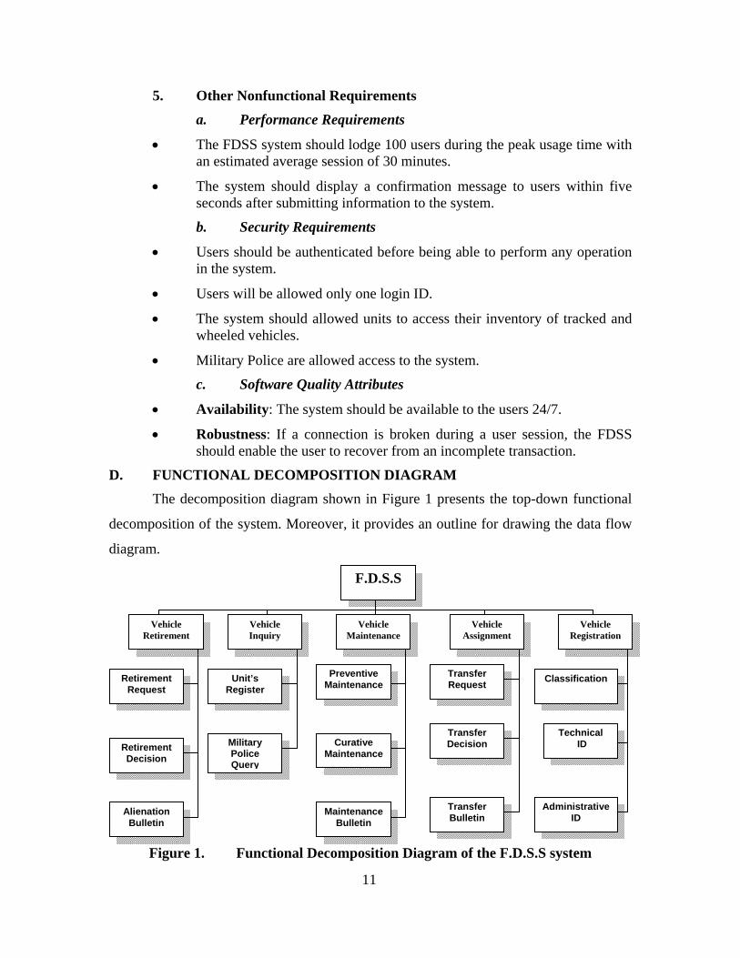
D. FUNCTIONAL DECOMPOSITION DIAGRAM The decomposition diagram shown in Figure 1 presents the top-down functional
decomposition of the system. Moreover, it provides an outline for drawing the data flow
diagram.
Figure 1. Functional Decomposition Diagram of the F.D.S.S system
F.D.S.S
Vehicle Inquiry
Vehicle Retirement
Retirement Request
Retirement Decision
Alienation Bulletin
Vehicle Maintenance
Preventive Maintenance
Curative Maintenance
Maintenance Bulletin
Administrative ID
Technical ID
Classification
Vehicle Registration
Military Police Query
Unit’s Register
Vehicle Assignment
Transfer Request
Transfer Decision
Transfer Bulletin
12
E. USE CASES
1. Use Case Diagram This section presents fifteen use cases to identify, analyze and understand the
informational system’s requirements. These use cases establish the desired behavior of
the system for verifying and validating the system architecture. Each use case
corresponds to a different functionality. Only the major steps that occur most of the time
are included in these use cases. Figure 2 depicts the use case hierarchy.

13
Figure 2. Use Case Hierarchy Diagram

14
2. Use Case Narratives
a. Create Catalog
Use case ID: UC-1
Use case name: Create Catalog Record. Created by: Chiheb Saidane Last Updated by: Chiheb Saidane
Date created: September 2 Date Last Updated: November 17 Actors: Director, Technical Service.
Description: This use case describes the creation of the catalog record. The Director of the department sends the approved classification of tracked and wheeled vehicles and the corresponding sustain and usage classes to the technical service (TS). A user from the TS enters the attributed classes to the database.
Preconditions: 1. Vehicle catalog record is created and added to the database.
Post conditions: 1. User is authenticated and role applied. 1a. User not logged in.
Normal Flow: 1.0 Create catalog record. 1. User chooses the catalog form. 2. System displays the catalog form. 3. User chooses add button. 4. User enters information related to the category of vehicle and
its corresponding usage class and sustain class. 5. System controls information and adds them to the database.
Exceptions:
1.0.E.1 Option System is not available now (step 1). 1. System notifies user that this option is not available. 2a. User requests to select another option. 2b. System restarts use case. 1.0.E.2 System reject (step 5). 1. System rejects information for the reason that the database is not available now and information is not stored.
Includes: None Priority: High Special
Requirements 1. User from the technical service shall be able to cancel the operation at any time prior to completion of steep 5.
Technical Data Catalog record: contains data identifying the category of vehicle, its usage class and sustain class.
15
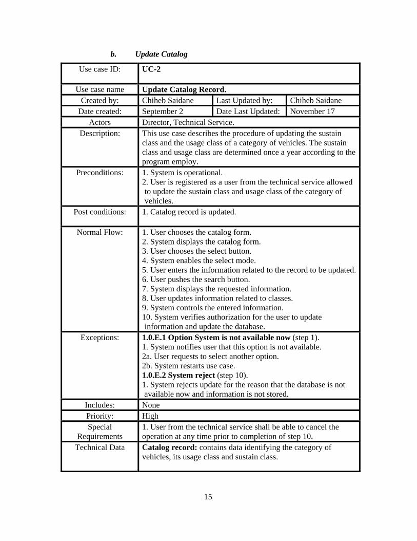
b. Update Catalog
Use case ID: UC-2
Use case name Update Catalog Record. Created by: Chiheb Saidane Last Updated by: Chiheb Saidane
Date created: September 2 Date Last Updated: November 17 Actors Director, Technical Service.
Description: This use case describes the procedure of updating the sustain class and the usage class of a category of vehicles. The sustain class and usage class are determined once a year according to the program employ.
Preconditions: 1. System is operational. 2. User is registered as a user from the technical service allowed to update the sustain class and usage class of the category of vehicles.
Post conditions: 1. Catalog record is updated.
Normal Flow: 1. User chooses the catalog form. 2. System displays the catalog form. 3. User chooses the select button. 4. System enables the select mode. 5. User enters the information related to the record to be updated.6. User pushes the search button. 7. System displays the requested information. 8. User updates information related to classes. 9. System controls the entered information. 10. System verifies authorization for the user to update information and update the database.
Exceptions:
1.0.E.1 Option System is not available now (step 1). 1. System notifies user that this option is not available. 2a. User requests to select another option. 2b. System restarts use case. 1.0.E.2 System reject (step 10). 1. System rejects update for the reason that the database is not available now and information is not stored.
Includes: None Priority: High Special
Requirements 1. User from the technical service shall be able to cancel the operation at any time prior to completion of step 10.
Technical Data Catalog record: contains data identifying the category of vehicles, its usage class and sustain class.

16
c. Delete Tracked/Wheeled Vehicles Categories
Use case ID: UC-3
Use case name: Delete Tracked/Wheeled Vehicles Categories. Created by: Chiheb Saidane Last Updated by: Chiheb Saidane
Date created: September 2 Date Last Updated: November 17 Actors: Director, Maintenance Service
Description: This use case describes the procedure for deleting a record from the catalog related to a category of vehicles. The maintenance service deletes the record of the specified category after the retirement of the last vehicle remaining in the category to delete.
Preconditions: 1. System is operational. 2. User is registered as a user from the maintenance service allowed to delete the information related to the category record.
Post conditions: 1. Vehicle category is deleted.
Normal Flow: 1.0 Delete tracked/wheeled vehicles categories.
1. User chooses the catalog form. 2. System displays the chosen form. 3. User chooses the select button. 4. User enters information related to the record to be deleted. 5. User pushes the execute button. 6. System displays information that satisfies the criteria specified.
7. User presses the delete button. 8. System verifies authorization for the user to delete information and update the database.
Exceptions:
1.0.E.1 Option System is not available now (step 1). 1. System notifies user that this option is not available. 2a. User requests to select another option. 2b. System restarts use case. 1.0.E.2 System reject (step 10). 1. System rejects delete information for the reason that the database is not available now and information is not deleted.
Includes: None Priority: High Special
Requirements 1. User from the maintenance service shall be able to cancel the operation at any time prior to completion of step 8.
Technical Data Catalog record: contains data identifying the category of tracked/wheeled vehicles, its usage class and sustain class.

17
d. Edit Catalog
Use case ID: UC-4
Use case name: Edit Catalog.
Created by: Chiheb Saidane Last Updated by: Chiheb Saidane Date created: September 2 Date Last Updated: November 17
Actors Director, Technical Service, Maintenance Service. Description: This use case describes the procedure for editing the catalog. The
procedure occurs after each update of the catalog. The set of records updated are edited and distributed to the units.
Preconditions: 1. System is operational. 2. User is registered as allowed to edit the catalog.
Post conditions: 1. User successfully edits the catalog entry.
Normal Flow: 1. User chooses the catalog form. 2. System displays the chosen form. 3. User chooses the select button. 4. System displays the criteria of selection form. 5. User enters information related to the records to be edited. 6. User pushes the edit button. 7. System edits the information that satisfies the criteria specified.
Exceptions:
1.0.E.1 Option System is not available now (step 1). 1. System notifies user that this option is not available. 2a. User requests to select another option. 2b. System restarts use case. 1.0.E.2 System reject (step 7). 1. System rejects edits information for the reason that the database is not available now.
Includes: None Priority: High Special
Requirements 1. User shall be able to cancel the operation at any time prior to completion of step 7.
Technical Data Catalog record: contains data identifying the category of tracked/wheeled vehicles, its usage class and sustain class.

18
e. Registration
Use case ID: UC-5
Use case name: Tracked/Wheeled Vehicle Registration. Created by: Chiheb Saidane Last Updated by: Chiheb Saidane
Date created: September 2 Date Last Updated: November 17 Actors: Technical service, maintenance service, logistic service,
verification and control service. Description: This use case describes the events for creating a tracked/wheeled
vehicle record. The tracked/wheeled vehicle record is composed of two parts. The first part concerns the technical identification. The second part concerns the administrative information.
Preconditions: 1. System is operational. 2. User is registered as user from the technical service.
Post conditions: 1. Vehicle is registered in the system.
Normal Flow: 1.0 Create tracked/wheeled vehicle record. 1. User chooses the tracked/wheeled vehicle registration form. 2. System displays the chosen form. 3. User chooses add button. 4. User enters information concerning the identification of the tracked/wheeled vehicle and specifies the corresponding catalog category to which the tracked/wheeled vehicle belongs to. 5. System controls information and stores them in the database.
Exceptions:
1.0.E.1 Option System is not available now. 1. System informs User that this option is not available. 2.1. User cancel request. 2.2. System ends use case. 3.1. User requests to select another option. 3.2. System restarts use case. 1.0.E.2 Can not Store information. 1. System informs User that the database is not available now and information is not stored.
Includes: None Priority: High Special
Requirements 1. User shall be able to cancel the operation at any time prior to completion of step 5.
Technical Data Tracked/wheeled vehicle record: contains the following information: track/wheeled vehicle license number, Designation, Identification number, category of vehicle, technical sheet ID, register ID, price, and owner.

19
f. Transfer Request
Use case ID: UC-6
Use case name Transfer Request.
Created by: Chiheb Saidane Last Updated by: Chiheb Saidane Date created: September 2 Date Last Updated: November 22
Actors Unit, Regional Department. Description: This use case describes the events for creating a tracked/wheeled
vehicle transfer request record. Preconditions: 1. System is operational.
2. User is registered as user from the unit allowed in creating the information related to the transfer request.
Post conditions: 1. Request is entered in the system.
Normal Flow: 1.0 Create transfer request record. 1. User chooses the transfer request form. 2. System displays the chosen form. 3. User chooses add button. 4. User enters information related to the category of tracked/wheeled vehicle and quantity requested. 5. System controls information and stores them in the database.
Exceptions:
1.0.E.1 Option System is not available now (step 1). 1. System notifies user that this option is not available. 2a. User requests to select another option. 2b. System restarts use case. 1.0.E.2 System reject (step 5). 1. System rejects creation for the reason that the database is not available now and information is not stored.
Includes: None Priority: High Special
Requirements 1. User shall be able to cancel the operation at any time prior to completion of step 5.
Technical Data Transfer request record: contains the following information: request number, request date, tracked/wheeled vehicle category, and quantity requested.

20
g. Transfer Decision
Use case ID: UC-7
Use case name: Transfer Decision.
Created by: Chiheb Saidane Last Updated by: Chiheb Saidane Date created: September 2 Date Last Updated: November 22
Actors: Director, Logistic Service, Technical Service. Description: This use case describes the procedure for creating a record for
the transfer decision of tracked/wheeled vehicle approved by the director.
Preconditions: 1. System operational. 2. User is registered as user from the logistic service allowed in creating the information related to the transfer decision.
Post conditions: 1. Transfer decision is entered in the system.
Normal Flow: 1.0 Create transfer decision record. 1. User chooses the decision transfer form. 2. System displays the chosen form. 3. User chooses add button. 4. User enters information related to category of tracked/wheeled vehicle to transfer, quantity, and decision date. 5. System controls information and adds them to the database.
Exceptions:
1.0.E.1 Option System is not available now (step 1). 1. System notifies user that this option is not available. 2a. User requests to select another option. 2b. System restarts use case. 1.0.E.2 System reject (step 5). 1. System rejects creation for the reason that the database is not available now and information is not stored.
Includes: None Priority: High Special
Requirements 1. User of the logistic service shall be able to cancel the operation at any time prior to completion of step 5.
Technical Data Transfer decision record: contains the following information: decision reference, decision date, tracked/wheeled vehicle category, and quantity approved.

21
h. Transfer Bulletin
Use case ID: UC-8
Use case name:
Transfer Bulletin Record.
Created by: Chiheb Saidane Last Updated by: Chiheb Saidane Date created: September 2 Date Last Updated: November 22
Actors:
Logistic Service, Unit, Technical Service, Verification & Control Service.
Description:
This use case describes the procedure of creating a transfer bulletin record. The transfer bulletin contains the information related to the tracked/wheeled vehicle to transfer.
Preconditions: 1. System is operational. 2. User is registered as user from the logistic service allowed in creating the information related to the transfer bulletin.
Post conditions: 1. Transfer Bulletin is entered in the system.
Normal Flow: 1.0 Create transfer bulletin record. 1. User chooses the transfer bulletin form. 2. System displays the chosen form. 3. User chooses add button. 4. User enters information related to the transfer decision:
reference number, tracked/wheeled vehicle category, and technical ID of the tracked/wheeled vehicle.
5. System controls information and adds the bulletin record to the database.
Exceptions:
1.0.E.1 Option System is not available now (step 1). 1. System notifies user that this option is not available. 2a. User requests to select another option. 2b. System restarts use case. 1.0.E.2 System reject (step 5). 1. System rejects creation for the reason that the database is not available now and information is not stored.
Includes: None Priority: High Special
Requirements 1. User of the logistic service shall be able to cancel the operation at any time prior to completion of step 5.
Technical Data Transfer bulletin record: contains information related to: bulletin reference, bulletin date, decision transfer, beneficiary, and license number of tracked/wheeled vehicle to transfer.

22
i. Update Tracked/Wheeled Vehicle Record
Use case ID: UC-9
Use case name: Update tracked/wheeled vehicle record.
Created by: Chiheb Saidane Last Updated by: Chiheb Saidane Date created: September 2 Date Last Updated: November 22
Actors: Logistic Service, Unit. Description: After creating the transfer bulletin, the logistic service user
updates the vehicle record by assigning the vehicle to the new owner.
Preconditions: 1. System is operational. 2. User is registered as user from the logistic service allowed in updating the vehicle record.
Post conditions: 1. Vehicle record is updated.
Normal Flow: 1.0 Update tracked/wheeled vehicle record. 1. User chooses the Vehicle option. 2. System displays the selected form. 3. User enters information related to the record to be updated. 4. System displays the vehicle record to be updated. 5. User updates the vehicle owner field. 6. System controls information and updates the vehicle record.
Exceptions:
1.0.E.1 Option System is not available now (step 1). 1. System notifies user that this option is not available. 2a. User requests to select another option. 2b. System restarts use case. 1.0.E.2 System reject (step 6). 1. System rejects edits of information for the reason that the database is not available now.
Includes: None Priority: High Special
Requirements 1. User of the logistic service shall be able to cancel the operation at any time prior to completion of step 6.
Technical Data Tracked/wheeled vehicle record: contains the following information: license number, Designation, Identification number, category of vehicle, technical sheet ID, register ID, price, and owner.
23
j. Create Preventive Maintenance Record
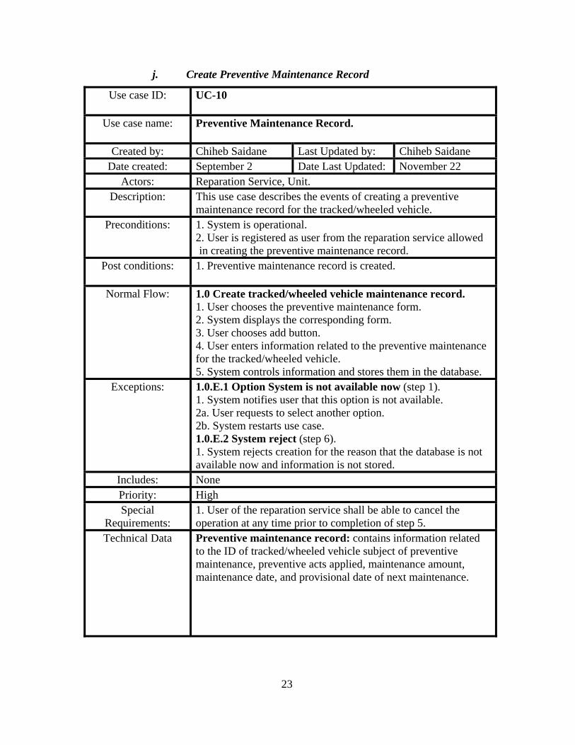
Use case ID: UC-10
Use case name: Preventive Maintenance Record.
Created by: Chiheb Saidane Last Updated by: Chiheb Saidane Date created: September 2 Date Last Updated: November 22
Actors: Reparation Service, Unit. Description: This use case describes the events of creating a preventive
maintenance record for the tracked/wheeled vehicle. Preconditions: 1. System is operational.
2. User is registered as user from the reparation service allowed in creating the preventive maintenance record.
Post conditions: 1. Preventive maintenance record is created.
Normal Flow: 1.0 Create tracked/wheeled vehicle maintenance record. 1. User chooses the preventive maintenance form. 2. System displays the corresponding form. 3. User chooses add button. 4. User enters information related to the preventive maintenance for the tracked/wheeled vehicle. 5. System controls information and stores them in the database.
Exceptions:
1.0.E.1 Option System is not available now (step 1). 1. System notifies user that this option is not available. 2a. User requests to select another option. 2b. System restarts use case. 1.0.E.2 System reject (step 6). 1. System rejects creation for the reason that the database is not available now and information is not stored.
Includes: None Priority: High Special
Requirements: 1. User of the reparation service shall be able to cancel the operation at any time prior to completion of step 5.
Technical Data Preventive maintenance record: contains information related to the ID of tracked/wheeled vehicle subject of preventive maintenance, preventive acts applied, maintenance amount, maintenance date, and provisional date of next maintenance.

24
k. Curative Maintenance Request
Use case ID: UC-11
Use case name Curative Maintenance Request. Created by: Chiheb Saidane Last Updated by: Chiheb Saidane
Date created: September 2 Date Last Updated: November 23 Actors Maintenance Service, Unit.
Description: Unit formulates a request to repair tracked/wheeled vehicle. The request describes briefly the tracked/wheeled vehicle problem.
Preconditions: 1. System is operational. 2. User is registered as user from the reparation service allowed in creating the curative maintenance request record.
Post conditions: 1. Curative maintenance request record is created.
Normal Flow:
1.0 Curative maintenance request. 1. User chooses the maintenance request form. 2. System displays the maintenance request form. 3. User chooses add button. 4. User enters information related to the maintenance request. 5. System controls the information added. 6. System stores information in the database.
Exceptions:
1.0.E.1 Option System is not available now (step 1). 1. System notifies user that this option is not available. 2a. User requests to select another option. 2b. System restarts use case. 1.0.E.2 System reject (step 6). 1. System rejects creation for the reason that the database is not available now and information is not stored.
Includes: None Priority: High Special
Requirements: 1. User of the reparation service shall be able to cancel the operation at any time prior to completion of step 6.
Technical Data Maintenance request record: contains information related to the identification of tracked/wheeled vehicle to fix, maintenance request date, problem description, and beneficiary.

25
l. Create Maintenance Bulletin
Use case ID: UC-12
Use case name: Create Maintenance Bulletin.
Created by: Chiheb Saidane Last Updated by: Chiheb Saidane Date created: September 2 Date Last Updated: November 23
Actors: Reparation Service. Description: After repairing the tracked/wheeled vehicle, the employee
mentions the cost of the repair operation. The reparation service introduces the maintenance request reference, acts of maintenance achieved, cost of maintenance, and date of maintenance.
Preconditions: 1. System is operational. 2. User is registered as user from the reparation service allowed in creating the curative maintenance request record.
Post conditions: 1. Maintenance bulletin is created.
Normal Flow: 1.0 Create maintenance bulletin.
1. User chooses the maintenance bulletin form. 2. System displays the chosen form. 3. User chooses add button. 4. User enters information related to the maintenance operation. 5. System controls information and adds them to the database.
Exceptions:
1.0.E.1 Option System is not available now (step 1). 1. System notifies user that this option is not available. 2a. User requests to select another option. 2b. System restarts use case. 1.0.E.2 System reject (step 5). 1. System rejects information for the reason that the database is not available now and information is not stored.
Includes: None Priority: High Special
Requirements: 1. User of the reparation service shall be able to cancel the operation at any time prior to completion of step 5.
Technical Data Maintenance bulletin record: contains information related to: license number of the vehicle, acts of maintenance applied, and maintenance amount.

26
m. Retirement Request
Use case ID: UC-13
Use case name: Retirement Request.
Created by: Chiheb Saidane Last Updated by: Chiheb Saidane Date created: September 2 Date Last Updated: November 23
Actors: Unit, Expert, Reparation Service. Description: This use case describes the procedure for creating a retirement
request when the tracked/wheeled vehicle is aged or seriously damaged and the maintenance is very expensive.
Preconditions: 1. System is operational. 2. User is registered as user from the reparation service allowed in creating the retirement request record.
Post conditions: 1. Retirement request record is created.
Normal Flow: 1.0 Retirement request. 1. User chooses the retirement request form. 2. System displays the chosen form. 3. User chooses add button. 4. User enters information related to the tracked/wheeled vehicle to retire. 5. System controls information and creates the retirement request record.
Exceptions:
1.0.E.1 Option System is not available now (step 1). 1. System notifies user that this option is not available. 2a. User requests to select another option. 2b. System restarts use case. 1.0.E.2 System reject (step 5). 1. System rejects information for the reason that the database is not available now and information is not stored.
Includes: None Priority: High Special
Requirements: 1. User of the reparation service shall be able to cancel the operation at any time prior to completion of step 5.
Technical Data Retirement request record: contains information concerning the tracked/wheeled vehicle to retire, motive of retirement, retirement request date, and the unit origin of the retirement proposal.

27
n. Retirement Decision
Use case ID: UC-14
Use case name: Retirement Decision. Created by: Chiheb Saidane Last Updated by: Chiheb Saidane
Date created: September 2 Date Last Updated: November 23 Actors: Maintenance Service, Director.
Description: This use case describes the procedure of creating the retirement decision record when the Director decides the retirement of the tracked/wheeled vehicle subject to the retirement request.
Preconditions: 1. System is operational. 2. User is registered as user from the maintenance service allowed in creating the retirement decision record.
Post conditions: 1. Retirement decision successfully entered in the system.
Normal Flow: 1.0 Retirement decision. 1. User chooses the retirement decision form. 2. System displays the chosen form. 3. User chooses the add button. 4. User enters information related to the tracked/wheeled vehicle to retire. 5. System controls information and creates the retirement decision record.
Exceptions:
1.0.E.1 Option System is not available now (step 1). 1. System notifies user that this option is not available. 2a. User requests to select another option. 2b. System restarts use case. 1.0.E.2 System reject (step 5). 1. System rejects creation for the reason that the database is not available now and information is not stored.
Includes: None Priority: High Special
Requirements: 1. User of the maintenance service shall be able to cancel the operation at any time prior to completion of step 5.
Technical Data Retirement decision record: contains information mentioning the tracked/wheeled vehicle to retire, reference of the retirement request, and date of the retirement decision.

28
o. Alienation Bulletin
Use case ID: UC-15
Use case name Alienation Bulletin. Created by: Chiheb Saidane Last Updated by: Chiheb Saidane
Date created: September 2 Date Last Updated: November 23 Actors Maintenance Service, Provision Service.
Description: After the execution of the retirement procedure, the tracked/wheeled vehicle is deleted from the department inventory.
Preconditions: 1. System is operational. 2. User is registered as user from the maintenance service allowed in creating the alienation record.
Post conditions: 1. Vehicle record is deleted from the system.
Normal Flow: 1.0 Alienation of a tracked/wheeled vehicle. 1. User chooses the alienation record form. 2. System displays the chosen form. 3. User chooses add button. 4. User enters the reference number of the retirement decision and information related to the tracked/wheeled vehicle to retire. 5. System controls information and adds them to the database 6. System deletes tracked/wheeled vehicle record from the department account.
Exceptions:
1.0.E.1 Option System is not available now (step 1). 1. System notifies user that this option is not available. 2a. User requests to select another option. 2b. System restarts use case. 1.0.E.2 System reject (step 5). 1. System rejects creation and deletion operations for the reason that the database is not available.
Includes: None Priority: High Special
Requirements: 1. User of the maintenance service shall be able to cancel the operation at any time prior to completion of step 6.
Technical Data Alienation bulletin record: contains information concerning the decision reference of the tracked/wheeled vehicle retired, the alienation date, and the reference of alienation bulletin.

29
F. SEQUENCE DIAGRAMS
Figure 3. Sequence Diagram SD-1.1: Create Catalog
Figure 4. Sequence Diagram SD-2.2: Update Catalog
1: SelectCatalogOption( )
System
2: Display Catalog form
5: InputCatalogData( )
6: Data controled
User
4: Provide Create Mode3: PressAddButton( )
7: ValidatecatalogData( )
8: Data Recorded* Until done
1: SelectCatalogOption( )
System
2: Display catalog form
3: PressSelectButton( )
5: EnterResearchCriteria( )
User
6: Display Catalog Data7: UpdateCatalogData( )
10: Data Updated
4: Provide Select mode
8: Data Controlled9: ValidateUpdateCatalogData( )
* Until done

30
Figure 5. Sequence Diagram SD-3.3: Delete Catalog
Figure 6. Sequence Diagram SD-4.4: Edit Catalog
1: SelectCatalogOption( )
System
2: Display Catalog Form3: PressSelectButton( )
5: EnterResearchCriteria( )
User
6: Display Catalog Data7: DeleteCatalogData( )8: Verify Data
4: Provides Select Mode
* Until done
9: Confirm Delete Data( )10: Data Deleted
1: SelectCatalogOption( )
System
2: Display Catalog Form3: PressSelectButton( )
5: EnterResearchCriteria( )
User
7: EditCatalog( )8: Catalog Info
4: Provides Select Mode
6: Info Data Found
* Until done

31
Figure 7. Sequence Diagram SD-5.5: Registration
Figure 8. Sequence Diagram SD-6.6: Transfer Request
1: SelectVehicleIdentificationOption( )
System
2: DisplayVehicleForm3: PressAddButton( )4: ProvidesCreateMode
User
5: ProvideVehicleInfo( )
7: ValidateVehicleData( )6: Vehicle Info Controlled
8: Data Recorded* Until done
1: SelectTransferRequestOption( )
System
2: Display Transfer Request Form3: PressAddButton( )4: Provide Add Mode
User
5: SubmitTransferInfo( )
8: Data Recorded
6: Data Controlled7: ValidateTransferInfo( )
* Until done

32
Figure 9. Sequence Diagram SD-7.7: Transfer Decision
Figure 10. Sequence Diagram SD-8.8: Assignment
1: SelectTransferDecisionOption( )
System
2: Display Transfer Decision Form
3: PressAddButton( )4: ProvidesAddMode
User
5: InputTransferDecisionData( )
8: Data Recorded
6: Data Controlled7: ValidateTransferDecisionData( )
* Until done
1: SelectTransferBulletinOption( )
System
2: Display Transfer Bulletin Form
3: PressIAddButton( )4: Provide Add Mode
User
5: SubmitTransferBulletinData( )
8: Data Added
6: Data Controlled7: ValidateTransferBulletindata( )
* Until done

33
Figure 11. Sequence Diagram SD-9.9: Update Vehicle Owner
Figure 12. Sequence Diagram SD-10.1: Preventive Maintenance
1: SelectVehicleOption( )System
2: Display Vehicle Form3: PressSelectButton( )
5: EnterResearchCriteria( )
User
7:UpdateVehicleOwner( )8: Data Updated
4: Provide Select Mode
6: Info Data Retrieved
* Until done
1: SelectPreventiveMaintenanceOption( )
System
2: Display Preventive Maintenance
5: InputPreventiveMaintenanceData( )
7: Preventive Maintenance Amount
Use
4: Provide Add Mode3: PressAddButton( )
8: ValidatePreventiveMaintenanceData( )9: Data Recorded
6: Data Controlled
* Until done

34
Figure 13. Sequence Diagram SD-11.1: Curative Bulletin
Figure 14. Sequence Diagram SD-12.1: Maintenance Request
1: SelectCurativeMaintenanceOption( )
System
2: Display Curative Maintenance Form
5: ProvidesCurativeMaintenanceActInfo( )
7: CurativeMaintenanceAmount
User
4: Provide Add Mode3: PressAddButton( )
8: ValidateCurativeMaintenanceInfo( )9: Data Recorded
6: Data Controlled
* Until done
1: SelectMaintenanceRequestOption( )
System
2: Display Maintenance Request
3: PressAddButton( )4: Provide Add Mode
User
5: InputMaintenanceRequestData( )
8: Data Recorded
6: Data Controlled7: ValidateMaintenanceRequestData( )
* Until done

35
Figure 15. Sequence Diagram SD-13.1: Retirement Request
Figure 16. Sequence Diagram SD-14.1: Retirement Decision
1: SelectRetirementRequestOption( )
System
2: Display Retirement Request Form3: PressAddButton( )
4: Provide Add Mode
User
5: SubmitRetirementRequestData( )6: Data Controlled
8: Data Recorded
7: ValidateRetirementRequestData( )
* Until done
1: SelectRetirementDecisionOption( )System
2: Display Retirement Decision Form3: PressAddButton( )4: Provide Add Mode
User
5: InputRetirementDecisionData( )
8: Data Recorded7: ValidateRetirementDecisionData( )
6: Data Controlled
* Until done
36
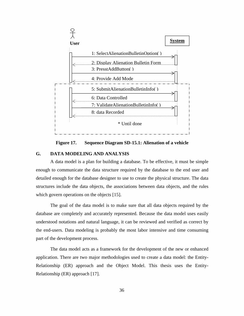
Figure 17. Sequence Diagram SD-15.1: Alienation of a vehicle G. DATA MODELING AND ANALYSIS
A data model is a plan for building a database. To be effective, it must be simple
enough to communicate the data structure required by the database to the end user and
detailed enough for the database designer to use to create the physical structure. The data
structures include the data objects, the associations between data objects, and the rules
which govern operations on the objects [15].
The goal of the data model is to make sure that all data objects required by the
database are completely and accurately represented. Because the data model uses easily
understood notations and natural language, it can be reviewed and verified as correct by
the end-users. Data modeling is probably the most labor intensive and time consuming
part of the development process.
The data model acts as a framework for the development of the new or enhanced
application. There are two major methodologies used to create a data model: the Entity-
Relationship (ER) approach and the Object Model. This thesis uses the Entity-
Relationship (ER) approach [17].
1: SelectAlienationBulletinOption( )
System
2: Display Alienation Bulletin Form3: PresstAddButton( )
4: Provide Add Mode
User
5: SubmitAlienationBulletinInfo( )
6: Data Controlled7: ValidateAlienationBulletinInfo( )8: data Recorded
* Until done
37
1. How are Data Models Used in Practice? There are three basic styles of data models:
• Conceptual data model (CDM): A CDM represents the overall logical structure of a database, which is independent of any software or data storage structure. A conceptual model often contains data objects not yet implemented in the physical database. It gives a formal representation of the data needed to run an enterprise or a business activity.
• Logical data model (LDM): LDM is used to explore the domain concepts and their relationships. The LDM depicts the logical entity types, typically referred to simply as entity types, the data attributes describing those entities, and the relationships between the entities.
• Physical data model (PDM): PDM is used to design the internal schema of a database, depicting the data tables, the data columns of those tables, and the relationships between the tables [15].
2. Conceptual Data Model Representation for the FDSS The conceptual data model (Figure 18) for the Decision Support System is
virtually divided into four parts. The first part concerns tracked/wheeled vehicle
registration (Figure 19). The second part concerns the transfer process (Figure 20). The
third part handles the maintenance of the tracked/wheeled vehicle (Figure 21). The fourth
part concerns the retirement process of the tracked/wheeled vehicle (Figure 22).
The data model has two outputs. The first is an entity-relationship diagram which
represents the data structures in a pictorial form (Figures 27, 28, 29, 30). The second is
the data dictionary which contains the details required for the construction of the physical
database.

38
Code usage
Catalog
Usage Class
Sustain Class
Vehicle
Cent Register
Tech Sheet
Employ
Registered
Classified
Sustain Transf RequestRequest line
Decision line
Transfer Decision
Transfer Bulletin
Generate
Unit
Concern
Establish
AttachedRegional Dept
Belong to
Bul line
Prev Bulletin
Plan
Prev Act
perform
Request
Maint Request
Required
Rep Bulletin
Cur Act
Repair
Ret Request
Reform
Alienate Ret Decision
Decide
Alienation Bulletin
Code unit
Code regional dept
T Bul number
T request numberCode line catCode sustain
Register reference
T sheet numberT decision number
License number
R request number
Ret decision number
Al bulletin numberRep bulletin number
Maint request number
Code cur act
Code prev act
Prev bulletin number
0,n
1,1
1,1
0,n1,n
1,11,1
1,1
0,n 0,n
0,n
0,n
0,n
0,n
1,1
1,1
0,n
1,1
0,n 0,n
1,1
0,n
1,1
0,n
0,n
0,n
1,1
0,n
0,n
0,n
0,n
1,1
1,1
0,n
0,n 0,n
1,1
1,1
0,n
0,n
1,1
Characterize
Figure 18. Conceptual Data Model Representation (FDSS)

39
vehicle
License number
CatalogSustain Class
Usage Class
Central Register Tech SheetRegistered
Classified
Characterized
Sustain
Employ
Code line cat Code sustain Code usage
Sheet numberCentral register number
0,n
1,1
1,n
1,1 1,1
0,n1,n
0,n
1,1
1,1
Figure 19. Conceptual Data Model Representation (Registration)
vehicle
License number
Transfer Request
Catalog
Unit
Transfer Bulletin
Transfer Decision
Historic Transfer
Decision Line
Classified
Request Trans Line
Establish
Transfer Request Number
Code Line catalog
Code Unit
Transfer Decision Number
Transfer Bulletin number
0,n
1,1
1,1
0,n
0,n0,n
1,1
0,n
Concern
0,n
Generate0,n
0,n
1,1
0,n 0,n
Regional DEPTCode regional dept
Attached
0,n
1,1 0,n
Belong to
0,n
1,1
Figure 20. Conceptual Data Model Representation (Transfer)

40
vehicle Preventive BulletinMaintenance Request
Curative Act
Preventive Act
Request
Repair
perform
Required
License Number Preventive bulletin number Maint request number
Code prev act
Code cur act
0,n
0,n
1,1
0,n
0,n
0,n
plan
Reparation Bulletin
Reparation bulletin number
1,1
1,1
0,n
0,n
Figure 21. Conceptual Data Model Representation (Maintenance)
Ret Request
Reform request number
vehicle
Ret Decision Alienation Bulletin
Decide
Reform
Alienate
License Number
Alienation bulletin numberReform decision number
1,1
0,n
1,1
1,1
0,n
0,n
Unit
Code Unit
Ask
1,1
0,n
Figure 22. Conceptual Data Model Representation (Retirement)

41
3. Data Dictionary A data dictionary is a structured collection of data element names and definitions.
It may illustrate all the data holdings of an organization, a part of the holdings or a single
database. More advanced data dictionaries can contain database schema with reference
keys and entity relationships.
A data dictionary is used to identify the data and the databases that contain it. The
data dictionary identifies data elements and their attributes including names, definitions
and units of measure and other information [16]:
• Data Element Domain: The context within which the data element exists.
• Data Element Name: Unique data element name from the application domain. This is the actual name of this data element.
• Data Element Definition: Description of the meaning of the data element.
• Data Element Field Name(s): Field names are the names used for this element in computer programs and database schemas. These are the technical names, often limited by the programming languages and systems.
• Data Element Data Type: Data type (characters, numeric, etc.), size and, if needed, any special representation. Common programming notation, input masks, etc can be used.
The Appendix shows the list of data collected for the FDSS system.
H. SYSTEM OPERATION CONTRACTS
Contract:
C-1 InputCatalogData(cod_lin, lab_lin,cod_usg, cod_sust).
Cross References:
- UC-1 Create Catalog Record.
- SD-1.1 Create Catalog.
Pre-conditions:
1. FDSS is operational.
2. An instance u of Usage Class exists.
3. An instance s of Sustain Class exists.

42
Post-conditions:
1. A new instance c of Catalog is created.
2. The FDSS informs the user about the creation completion.
------------------------------------------------------------------------------------------
Contract:
C-2 UpdateCatalogData(cod_lin, cod_usg, cod_sust).
Cross Reference:
- UC-2 Update Catalog Record.
- SD-2.2 Update Catalog.
Pre-conditions:
1. FDSS is operational.
2. An instance c of Catalog exists.
2. An instance u of Usage Class exists.
3. An instance s of Sustain Class exists.
Post-conditions:
1. The instance c of Catalog is updated.
2. The FDSS informs the user of the update completion.
------------------------------------------------------------------------------------------
Contract:
C-3 DeleteCatalogData(cod_lin, lab_li, cod_usg, cod_sust).
Cross References:
- UC-3 Delete Tracked/Wheeled Vehicles Categories.
- SD-3.3 Delete Catalog Line.
Pre-conditions:
1. FDSS is operational.
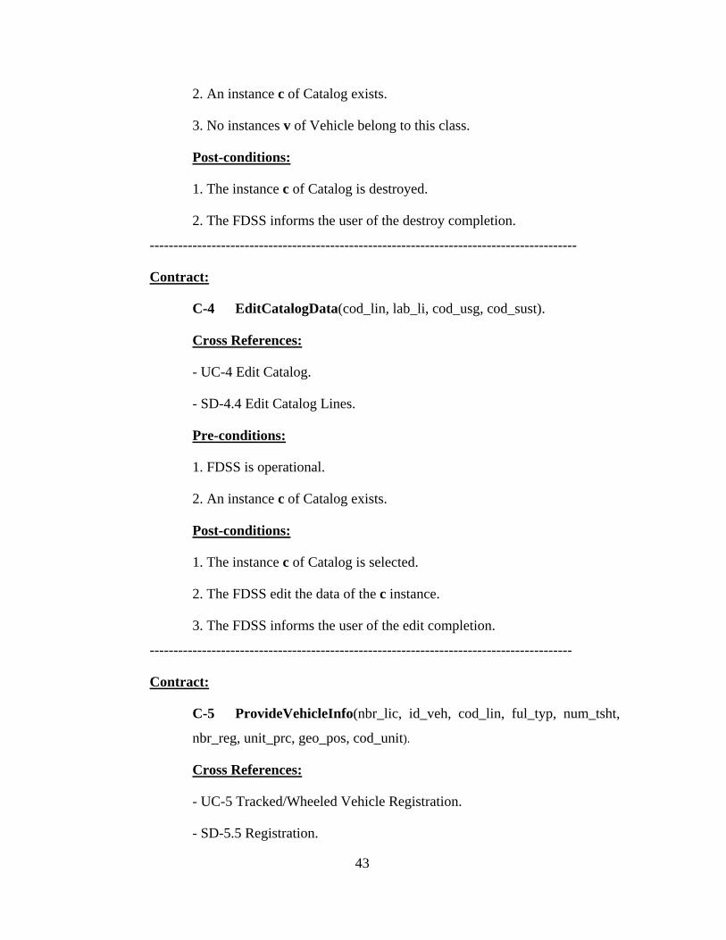
43
2. An instance c of Catalog exists.
3. No instances v of Vehicle belong to this class.
Post-conditions:
1. The instance c of Catalog is destroyed.
2. The FDSS informs the user of the destroy completion.
------------------------------------------------------------------------------------------
Contract:
C-4 EditCatalogData(cod_lin, lab_li, cod_usg, cod_sust).
Cross References:
- UC-4 Edit Catalog.
- SD-4.4 Edit Catalog Lines.
Pre-conditions:
1. FDSS is operational.
2. An instance c of Catalog exists.
Post-conditions:
1. The instance c of Catalog is selected.
2. The FDSS edit the data of the c instance.
3. The FDSS informs the user of the edit completion.
-----------------------------------------------------------------------------------------
Contract:
C-5 ProvideVehicleInfo(nbr_lic, id_veh, cod_lin, ful_typ, num_tsht,
nbr_reg, unit_prc, geo_pos, cod_unit).
Cross References:
- UC-5 Tracked/Wheeled Vehicle Registration.
- SD-5.5 Registration.
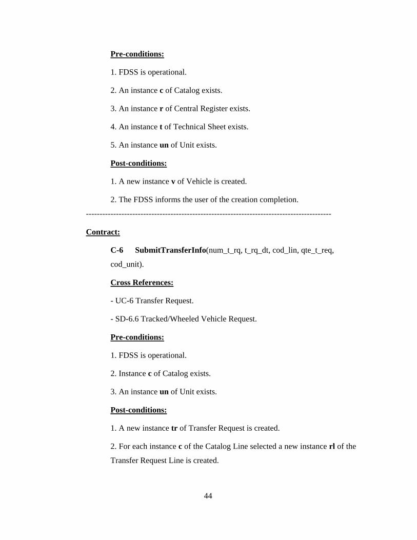
44
Pre-conditions:
1. FDSS is operational.
2. An instance c of Catalog exists.
3. An instance r of Central Register exists.
4. An instance t of Technical Sheet exists.
5. An instance un of Unit exists.
Post-conditions:
1. A new instance v of Vehicle is created.
2. The FDSS informs the user of the creation completion.
------------------------------------------------------------------------------------------
Contract:
C-6 SubmitTransferInfo(num_t_rq, t_rq_dt, cod_lin, qte_t_req,
cod_unit).
Cross References:
- UC-6 Transfer Request.
- SD-6.6 Tracked/Wheeled Vehicle Request.
Pre-conditions:
1. FDSS is operational.
2. Instance c of Catalog exists.
3. An instance un of Unit exists.
Post-conditions:
1. A new instance tr of Transfer Request is created.
2. For each instance c of the Catalog Line selected a new instance rl of the
Transfer Request Line is created.

45
3. The FDSS informs the user of the creation success.
------------------------------------------------------------------------------------------
Contract
C-7 InputTransferDecisionData(num_t_dec, t_dec_dt, d_trs_obs,
num_t_rq, cod_lin, obj_t_dec).
Cross References:
- UC-7 Transfer Decision.
- SD-7.7 Transfer Decision.
Pre-conditions:
1. FDSS is operational.
2. Instances c of Catalog exist.
3. An instance tr of Transfer Request exists.
Post-conditions:
1. A new instance td of Transfer Decision is created.
2. For each instance c of Catalog specified a new instances dl of the
Decision Line is created.
3. The FDSS informs the user of the creation completion.
------------------------------------------------------------------------------------------
Contract:
C-8 SubmitTransferBulletinData(num_bul, nbr_lic, Dat_bul,
num_tdec, cod_unt).
Cross References:
- UC-8 Transfer bulletin.
- SD-8.8 Assignment of Vehicle.
Pre-conditions:
1. FDSS is operational.

46
2. An instance un of Unit exists.
3. Instances v of Vehicle exists.
4. An instance td of Transfer Decision exists.
Post-conditions:
1. A new instance tb of Transfer Bulletin is created.
2. For each instance v of Vehicle specified a new instances dt of Detail
Transfer Bulletin is created.
3. The FDSS informs the user of the creation success.
------------------------------------------------------------------------------------------
Contract:
C-9 UpdateVehicleOwner(nbr_lic, cod_unit).
Cross Reference:
- UC-9 Update tracked/wheeled vehicle record.
- SD-9.9 Update vehicle owner.
Pre-conditions:
1. FDSS is operational.
2. An instance tb of Transfer Bulletin exists.
3. An instance dt of Detail Transfer exists.
4. An instance v of Vehicle exists.
Post-conditions:
1. The instance v of Vehicle is updated.
2. The FDSS informs the user of the update completion.
------------------------------------------------------------------------------------------

47
Contract:
C-10 InputPreventiveMaintenanceData(num_pr_bul, nbr_lic
,pr_bt_dt, pr_b_amt, nwpr_dat, cd_p_act, p_prt_mt).
Cross References
- UC-10 Preventive Maintenance Record.
- SD-10.1 Preventive Maintenance.
Pre-conditions:
1. FDSS is operational.
2. An instance v of Vehicle exists.
3. An instance pa of Preventive Act exists.
Post-conditions:
1. A new instance pb of Preventive Bulletin is created.
2. For each instance pa of Preventive Act specified a new instance p of
perform is created.
3. The FDSS informs the user of the creation success.
------------------------------------------------------------------------------------------
Contract:
C-11 ProvideCurativeMaintenanceActInfo(num_Rbul, r_bul_dt,
num_mreq, t_rpamt, c_cu_act, mt_r_act, wk_desc).
Cross References:
- UC-12 Create Maintenance Bulletin.
- SD-11.1 Curative Bulletin.
Pre-conditions:
1. FDSS is operational.
2. An instance v of Vehicle exists.

48
3. An instance mr of Maintenance Request exists.
4. An instance ca of Curative Act exists.
Post-conditions:
1. A new instance rb of Reparation Bulletin is created.
2. For each instance ca of Curative Act entered a new instance r of Repair
is created.
3. The FDSS informs the user of the creation success.
------------------------------------------------------------------------------------------
Contract:
C-12 InputMaintenanceRequestData(num_mreq, nbr_lic, nbr_m_st,
m_req_dt, obs_mreq).
Cross References:
- UC-11 Curative Maintenance Request Record.
- SD-12.1 Maintenance Request.
Pre-conditions:
1. FDSS is operational.
2. An instance v of Vehicle exists.
Post-conditions:
1. A new instance mr of Maintenance Request is created.
2. The FDSS informs the user of the creation completion.
------------------------------------------------------------------------------------------
Contract:
C-13 SubmitRetirementRequestData(num_r_rq, nbr_lic, r_req_dt,
mot_ref, r-rq_obs, cod_unit).
Cross References:
- UC-13 Retirement Request.

49
- SD-13.1 Retirement Request.
Pre-conditions:
1. FDSS is operational.
2. An instance v of Vehicle exists.
3. An instance un of Unit exists.
Post-conditions:
1. A new instance rr of Retirement Request is created.
2. The FDSS informs the user of the creation completion.
------------------------------------------------------------------------------------------
Contract:
C-14 InputRetirementDecisionData(nm_rf_dec, num_r_rq, r_dec_dt,
o_rf_dec).
Cross References:
- UC-14 Retirement Decision.
- SD-14.1 Retirement Decision.
Pre-conditions:
1. FDSS is operational.
2. An instance rr of Retirement Request exists.
Post-conditions:
1. A new instance refd of Retirement Decision is created.
2. The FDSS informs the user of the creation completion.
------------------------------------------------------------------------------------------
Contract:
C-15 SubmitAlienationBulletinInfo(num_bl_al, nm_rf_dec, a_bul_dt).
Cross References:
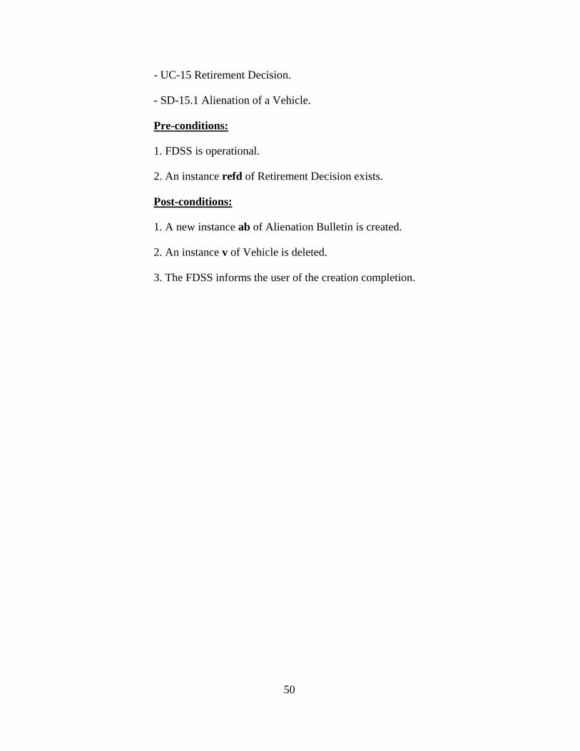
50
- UC-15 Retirement Decision.
- SD-15.1 Alienation of a Vehicle.
Pre-conditions:
1. FDSS is operational.
2. An instance refd of Retirement Decision exists.
Post-conditions:
1. A new instance ab of Alienation Bulletin is created.
2. An instance v of Vehicle is deleted.
3. The FDSS informs the user of the creation completion.

51
III. DESIGN PHASE
A. APPLICATION ARCHITECTURE AND IMPLEMENTATION
1. Description In the FDSS system environment, which is an Oracle environment, the FDSS
application and the FDSS database are separated into two parts: the front-end or client
portion, and the back-end or server portion. The client runs the FDSS application that
accesses the FDSS database information and interacts with the user through the keyboard,
screen, and mouse. The server runs the Oracle software and handles the functions
required for concurrent, shared data access to the database. Figure 23 illustrates the
architecture of the system where the client and server are located on different computers,
and these computers are connected through a network. The server and clients
communicate through Oracle Net Services, Oracle's network interface.
Figure 23. FDSS Client/Server Architecture (From: [13])

52
2. The Use of Oracle Net Services in the FDSS System
a. Support Network Oracle Net Services enables a network session from the client FDSS
application to the FDSS database. It is responsible for establishing and maintaining the
connection between the application and database server.
b. How Oracle Net Services Works in the FDSS System Oracle's support network protocols provides an interface between Oracle
processes running on the database server and the FDSS application running on other
computers of the network. Oracle protocols take SQL statements from the interface of the
FDSS application and package them for transmission to Oracle through the supported
higher level protocols. The protocols also take replies from Oracle and package them for
transmission to the application through the same higher level communications
mechanism [14].
c. Stack Communication for the FDSS Client/Server Application Connections
Figure 24 illustrates the various layers on the client and on the database
server after a connection has been established.
Figure 24. Identification of Layers used in the FDSS Client/Server Application Connection (After [14])

53
During a session with the database, the FDSS client uses Oracle Call
Interface (OCI) to interact with the database server. OCI is a software component that
provides an interface between the FDSS client application and the SQL language that the
database server understands.
The presentation layer used by the FDSS client/server application is Two-
Task Common (TTC). TTC provides character set and data type conversion between
different character sets or formats on the client and database server.
The Oracle Net foundation layer is responsible for establishing and
maintaining the connection between the FDSS client application and database server, as
well as exchanging messages between them [14].
3. Listener Architecture The database server receives an initial connection from the FDSS client
application through the listener. The listener is an application positioned on top of the
Oracle Net foundation layer. The following figure (Figure 25) illustrates the various
layers on the client and database server during an initial connection.
Figure 25. Layers Used in an Initial Connection (After [14])
The listener brokers the FDSS client requests, handing off the requests to the
Oracle database server. Every time the FDSS client requests a network session with a
database server, a listener receives the initial request [14].
Figure 26 shows the role of a listener during connection establishment with a
client making a TTC connection:

54
(1) The database registers information about the services, instances, and service handlers with the listener.
(2) The client makes an initial connection with the listener.
(3) The listener parses the client request and forwards it to the service handler for the database service requested.
Figure 26. Listener Architecture (After [14]) B. OBJECT MODEL REPRESENTATION
The mapping from the Conceptual Data Model (CDM) to the Object Model
consists to transform CDM objects into specified object language objects by applying the
following rules.
1. Independent One-to-Many Relationships In independent one-to-many relationships, the primary identifier of the entity on
the one side of the relationship becomes a:
• Primary key in the entity on the one side of the relationship;
• Foreign key in the entity on the many side of the relationship.
2. Dependent One-to-Many Relationships
In dependent relationships, the primary identifier of the nondependent entity
becomes a primary/foreign key in the dependent entity.
TTC Presentation Over TCP/IP
TTC Presentation Over TCP/IP
Database 1 2
3
3

55
3. Independent Many-to-Many Relationships In independent many-to-many relationships, the primary identifiers of both
entities migrate to a join entity as primary/foreign keys.
4. Independent One-to-One Relationships In independent one-to-one relationships, the primary identifier of one entity
migrates to the other generated entity as a foreign key.
Conceptual Data Model
Object Oriented Model
Entity
Class
Association
Relationship or association
Binary association with attributes
Association class
Attribute
Attribute
Inheritance
Generalization
Table 2. Transformation of a CDM to an OOM
Vehicle
± License number… …
CatalogSustain Class
Usage Class
Central register Tech Sheet
± Code line cat… …
± Code sustain… …
± Code usage… …
± Sheet number… …
± Central register number… …
0..*
1..1
0..*
1..1
1..1
0..*
0..*
0..*
1..1
1..1
+ Create Truck/vehicle()+ Update Truck/vehicle()+ Select Truck/vehicle()+ Delete Truck/vehicle()
Figure 27. Object Model: Registration

56
Vehicle
± License number… …
Transfer Request
CatalogUnit
Transfer Bulletin
Transfer Decision
± Transfer Request Number… …
± Code Line catalogue… …
± Code Unit… …
± Transfer Decision Number… …
± Transfer Bulletin number… …
0..*
0..*
0..*
0,n
0..*
0..*
1..1
0..*
1..1
0..*
0..*
1..1 0..*
1..1
Regional Dept± Code regional dept… …
0..*
1..1
0..*Decision Line
Qte dec trans
Trans Request Line
Qte trans
Historic Transfer
Transfer date
1..1
0..*
Figure 28. Object Model: Transfer
Vehicle Preventive BulletinMaintenance Request
Curative ActPreventive Act
± License Number… …
± Preventive bulletin number… …
± Maint request number
… …
± Code prev act … …± Code cur act
… …
0..n
0..*
1..1
0..*
0..*
0..n
Reparation Bulletin
± Rep bulletin number … …
1..1
1..1
0..n
0..*
Repair
+ Repair amount
Perform
+ Prev act amout
Figure 29. Object Model: Maintenance

57
Ret Request
± Ret request number… …
Vehicle
Ret Decision Alienation Bulletin
± License Number… …
± Alienation bulletin number… …
± Ret decision number… …
1..1
0..*
1..1
1..1
0..*
0..*
Unit± Code Unit… …
1..1
0..*
Figure 30. Object Model: Retirement
C. DATABASE SQL SCRIPT CREATE TABLE lcat (
cod_lin VARCHAR(15) PRIMARY KEY,
lab_lin VARCHAR(50),
cod_usg VARCHAR(3),
cod_sust VARCHAR(3),
FOREIGN KEY (COD_USG) REFERENCES UCLASS (COD_USG),
FOREIGN KEY (COD_SUST) REFERENCES SCLASS(COD_SUST));
CREATE TABLE sclass (
cod_sust VARCHAR(3) PRIMARY KEY,
lab_sust VARCHAR(40));
CREATE TABLE uclass (
cod_usg VARCHAR(3) PRIMARY KEY,
lab_usg VARCHAR(20));

58
CREATE TABLE cent_reg (
nbr_reg VARCHAR(15) PRIMARY KEY,
cent_dat DATE,
hol_reg VARCHAR(40));
CREATE TABLE vehicle(
nbr_lic VARCHAR(15) PRIMARY KEY,
id_veh VARCHAR(25),
cod_lin VARCHAR(15),
ful_typ VARCHAR(20),
cod_unit VARCHAR(15),
num_tsht VARCHAR(20),
nbr_reg VARCHAR(15),
unit_prc DECIMAL(12,3),
geo_pos VARCHAR(40),
FOREIGN KEY (COD_LIN) REFERENCES LCAT (COD_LIN),
FOREIGN KEY (COD_UNIT) REFERENCES UNIT(COD_UNIT),
FOREIGNKEY (NUM_TSHT) REFERENCES
TECH_SHT(NUM_TSHT),
FOREIGN KEY (NBR_REG) REFERENCES CENT_REG
(NBR_REG));
CREATE TABLE tech_sht (
num_tsht VARCHAR(20) PRIMARY KEY,
dat_sht DATE,
pro_sht VARCHAR(30));
CREATE TABLE reg_dept (
cod_dept VARCHAR(8) PRIMARY KEY,
lab_dept VARCHAR(40),
adr_dept VARCHAR(40),
tel_dept VARCHAR(15));

59
CREATE TABLE unit (
cod_unit VARCHAR(15) PRIMARY KEY,
nam_unit VARCHAR(40),
cod_dept VARCHAR(8),
cod_arm VARCHAR(8),
adr_unit VARCHAR(50),
tel_unit VARCHAR(15),
FOREIGN KEY (COD_DEPT) REFERENCES REG_DEPT
(COD_DEPT));
CREATE TABLE transf_bl (
num_bul VARCHAR(20) PRIMARY KEY,
dat_bul DATE,
num_tdec VARCHAR(20),
cod_unit VARCHAR(15),
FOREIGN KEY (NUM_TDEC) REFERENCES TRS_DEC
(NUM_TDEC),
FOREIGN KEY (COD_UNIT) REFERENCES UNIT (COD_UNIT));
CREATE TABLE trans_rq (
num_t_rq VARCHAR(20) PRIMARY KEY,
cod_unit VARCHAR(15),
t_req_dt DATE,
FOREIGN KEY (COD_UNIT) REFERENCES UNIT (COD_UNIT));
CREATE TABLE tr_rq_li(
num_t_rq VARCHAR(20),
cod_lin VARCHAR(15),
qte_t_req INTEGER,
tr_r_obs VARCHAR(50),
FOREIGN KEY (NUM_T_RQ) REFERENCES TRANS_RQ
(NUM_T_RQ),

60
FOREIGN KEY (COD_LIN) REFERENCES LCAT (COD_LIN),
PRIMARY KEY (NUM_T_RQ, COD_LIN));
CREATE TABLE trs_dec(
num_tdec VARCHAR(20) PRIMARY KEY,
t_dec_dt DATE,
d_trs_obs VARCHAR(50));
CREATE TABLE dec_ln(
num_tdec VARCHAR(20),
num_t_rq VARCHAR(20),
cod_lin VARCHAR(15),
obj_tdec VARCHAR(50),
qte_tdec INTEGER,
FOREIGN KEY (NUM_TDEC) REFERENCES TRS_DEC
(NUM_TDEC),
FOREIGN KEY (NUM_T_RQ) REFERENCES TRANS_RQ
(NUM_T_RQ),
FOREIGN KEY (COD_LIN) REFERENCES LCAT (COD_LIN),
PRIMARY KEY (NUM_TDEC, NUM_T_RQ, COD_LIN ));
CREATE TABLE hy_trans(
num_bul VARCHAR(20),
nbr_lic VARCHAR(15),
FOREIGN KEY (NUM_BUL) REFERENCES TRANSF_BL
(NUM_BUL),
FOREIGN KEY (NBR_LIC) REFERENCES VEHICLE (NBR_LIC),
PRIMARY KEY (NUM_BUL, NBR_LIC));
CREATE TABLE main_req(
num_mreq VARCHAR(20) PRIMARY KEY,
nbr_lic VARCHAR(15),

61
nbr_m_st VARCHAR(12),
m_req_dt DATE,
obs_mreq VARCHAR(50),
FOREIGN KEY (NBR_LIC) REFERENCES VEHICLE (NBR_LIC));
CREATE TABLE rep_bul(
num_rbul VARCHAR(20) PRIMARY KEY,
r_bul_dt DATE,
num_mreq VARCHAR(20) ,
FOREIGN KEY (NUM_MREQ) REFERENCES MAIN_REQ
(NUM_MREQ));
CREATE TABLE rep (
num_rbul VARCHAR(20) ,
c_cu_act VARCHAR(20),
nbr_hr INTEGER,
FOREIGN KEY (NUM_RBUL) REFERENCES REP_BUL
(NUM_RBUL),
FOREIGN KEY (C_CU_ACT) REFERENCES CU_ACT (C_CU_ACT),
PRIMARY KEY (NUM_RBUL, C_CU_ACT));
CREATE TABLE cu_act (
c_cu_act VARCHAR(10) PRIMARY KEY,
m_cu_lab VARCHAR(40),
mth_r_act DECIMAL(12,3));
CREATE TABLE pre_bul(
num_pr_b VARCHAR(20) PRIMARY KEY,
nbr_lic VARCHAR(15),
pr_bt_dt DATE,
nwpr_dat DATE,

62
FOREIGN KEY (NBR_LIC) REFERENCES VEHICLE (NBR_LIC));
CREATE TABLE perform(
num_pr_b VARCHAR(20),
cd_p_act VARCHAR(10),
pact_qty INTEGER,
FOREIGN KEY (NUM_PR_B) REFERENCES PRE_BUL
(NUM_PR_B),
FOREIGN KEY (CD_P_ACT) REFERENCES
PREV_ACT(CD_P_ACT),
PRIMARY KEY (NUM_PR_B, CD_P_ACT));
CREATE TABLE prev_act(
cd_p_act VARCHAR(10) PRIMARY KEY,
l_pr_act VARCHAR(40),
p_prt_mt DECIMAL(12,3));
CREATE TABLE ref_req(
num_r_rq VARCHAR(20) PRIMARY KEY,
nbr_lic VARCHAR(15),
cod_unit VARCHAR(15),
r_req_dt DATE,
mot_rf VARCHAR(20),
r_rq_obs VARCHAR(50),
FOREIGN KEY (COD_UNIT) REFERENCES UNIT (COD_UNIT),
FOREIGN KEY (NBR_LIC) REFERENCES VEHICLE (NBR_LIC));
CREATE TABLE ref_dec(
nm_rf_dec VARCHAR(20) PRIMARY KEY,
num_r_rq VARCHAR(20),
r_dec_dt DATE,
o_rf_dec VARCHAR(50),

63
FOREIGN KEY (NUM_R_RQ) REFERENCES
REF_REQ(NUM_R_RQ));
CREATE TABLE alie_bul(
nm_bl_al VARCHAR(20) PRIMARY KEY,
a_bul_dt DATE,
nm_rf_dec VARCHAR(20),
cod_a_dest VARCHAR(10),
FOREIGN KEY (NM_RF_DEC) REFERENCES REF_DEC
(NM_RF_DEC));

64
THIS PAGE INTENTIONALLY LEFT BLANK

65
IV. PROTOTYPE
A. COMMON FUNCTIONALITIES
1. Connection To start the FDSS application the authorized user needs to connect to the system.
He must enter his user name and password. Figure 31 shows the process of connection to
the system.
Figure 31. Connection Screen
2. Common Functionalities For all functionalities of the system the standard screen shown in Figure 32 is
implemented.
Figure 32. Standard Screen
Each option of the standard screen presents a set of functions that are available depending
on the selected option, an example of which is shown in Figure 33.

66
Figure 33. Functions Menu Screen
Under the Menu Bar, the tools bar displays a set of icons representing the different
functionalities available to use by simple clicking using the mouse (Figure 34).
Figure 34. Tool Bar Menu
Besides the Tool Bar, the standard screen presents a Status Bar on the bottom of
the screen that indicates the current option in use, shown below in Figure 35.
Figure 35. Status Bar Options
B. PRESENTATION OF THE GENERAL MENU
The following menu (Figure 36) presents the software developed to cover the
different functionalities of the FDSS system.

67
Figure 36. FDSS Main Menu
1. Registration Module
a. Catalog Screen The screen shown in Figure 37 presents the management of categories of
vehicles.
Figure 37. Catalog Screen

68
b. Usage Class Screen The screen shown in Figure 38 allows add, query, update, and delete a
usage class of a vehicle.
Figure 38. Usage Class Screen
c. Sustain Class Screen The screen below in Figure 39 allows the user to add, query, update, and
delete a sustain class of a vehicle.
Figure 39. Sustain Class Screen

69
d. Edit Catalog Screen The following screen (Figure 40) presents the option for editing of
categories of vehicles.
Figure 40. Edit Criteria Screen
e. Vehicle Identification Screen The vehicle identification is accessible via the screen shown in Figure 41.
Figure 41. Vehicle Identification Screen

70
f. Central Register Screen The screen shown in Figure 42 allows the search of the registers of
vehicles and their holders.
Figure 42. Central Register Screen
g. Technical Sheet Screen The screen shown in Figure 43 allows the identification of military
wheeled and tracked vehicle technical sheet producers.

71
Figure 43. Technical Sheet Screen
2. Transfer Module
a. Transfer Request Screen The screen in Figure 44 allows the user to add records of the transfer
request of military wheeled and tracked vehicles.
Figure 44. Transfer Request Screen

72
b. Transfer Decision Screen The screen shown in Figure 45 allows for the creation of transfer decision
records of categories of vehicles assigned to units.
Figure 45. Transfer Decision Screen
c. Transfer Bulletin Screen The screen in Figure 46 allows the assignment of tracked and wheeled
vehicles to units.
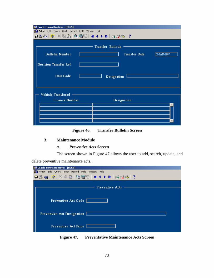
73
Figure 46. Transfer Bulletin Screen
3. Maintenance Module
a. Preventive Acts Screen The screen shown in Figure 47 allows the user to add, search, update, and
delete preventive maintenance acts.
Figure 47. Preventative Maintenance Acts Screen

74
b. Preventive Maintenance Bulletin Screen The screen shown in Figure 48 allows the user to record all preventive
maintenances of tracked and wheeled vehicles.
Figure 48. Preventative Maintenance Bulletin Screen
c. Curative Acts Screen The screen shown in Figure 49 allows the user to add, search, update, and
delete curative maintenance acts.

75
Figure 49. Curative Maintenance Acts Screen
d. Maintenance Request Screen The screen shown below in Figure 50 presents an application to start the
process of curative maintenance of a vehicle.
Figure 50. Curative Maintenance Request Screen

76
4. Inquiry
a. Military Units Screen The screen in Figure 51 shows the feature of searching for the unit’s data.
Figure 51. Military Units Screen
b. Regional Department Screen The screen shown in Figure 52 allows the user to search for the regional
Departments.
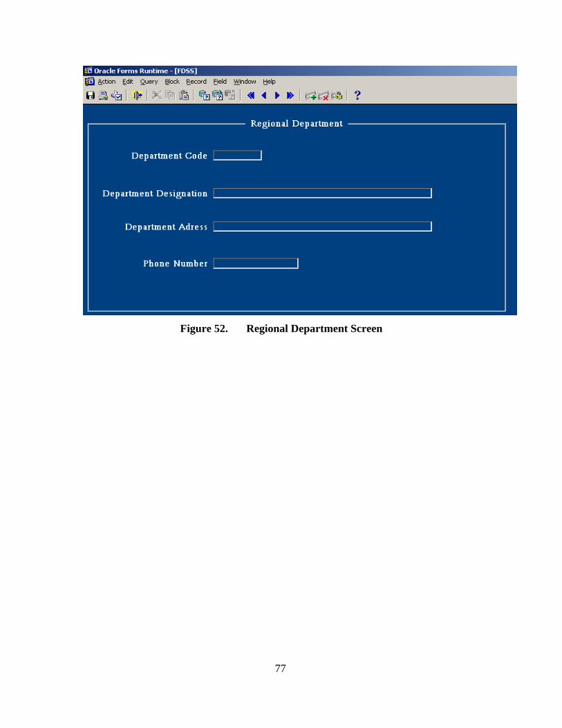
77
Figure 52. Regional Department Screen

78
THIS PAGE INTENTIONALLY LEFT BLANK

79
V. SUMMARY AND CONCLUSION
A. SUMMARY This thesis developed a solution to provide and make available instantaneous and
accurate information that will be used to derive the right decision on time regarding the
management of a military tracked and wheeled vehicle fleet. Chapter II stated the system
requirements specification and analyzes these requirements. Chapter III presented the
details of the system design and the database scheme. Chapter IV provided the system
prototype, developed using the Oracle DBMS, and the necessary interfaces for the users
to enhance the benefits of this software. This study will improve the decision making
ability of the leader of this department. It will make the routine tasks easier, and enforce
the control process concerning the usage and maintenance of military vehicles.
B. INFORMATION SYSTEM A major challenge in developing a thorough Fleet Decision Support System is
finding what information is available. What information will be needed to meet the
requirements? And how this information will be presented to the end-user? The best
people to answer these questions are those who are knowledgeable about fleet
management and are part of the information system. Moreover, the greatest success in
implementing this kind of information system relies on an effective plan that provides an
incremental but continuous integration of new functionalities. These new functionalities
should apply to both the core fleet management information system and to ancillary tools
that complement and enhance it.
C. PLATFORM AND NETWORK CONSIDERATIONS Another major consideration in developing a Fleet Decision Support System
relates to the platform that will be utilized to deliver tools to end users. There are a
variety of platforms available today. However, client server architecture and the Intranet
are clearly dominating the technology industry as the platforms of choice. The principal
virtue of these platforms is that they facilitate the efficient and inexpensive distribution
and maintenance of applications to multiple end users. They also support another trend

80
that promises to further change the definition of effective fleet management: providing
real-time access for fleet users to the detailed information that historically has been
available only to fleet managers.
D. RECOMMENDATIONS Several future tasks that need to be completed are as follows:
• Development of the curative maintenance and retirement subsystems.
• Development of a module related to the inventory of tracked and wheeled vehicles of units.
• Test and integrate the newly developed subsystems and modules to the system.
• Test the entire system and verify the behavior of each subsystem.
• Train the users to use and interact with the system properly.
• The software maintenance phase will determine the success of this project.

81
APPENDIX. DATA DICTIONARY
Data Element Name Field Name Code Format
Address regional department adr_dept VarChar(40)
Address unit/regiment adr_unit VarChar(50)
Alienation bulletin date a_bul_dt Date
Alienation bulletin number nm_al_bl VarChar(20)
Alienation code destination cod_a_dst VarChar(10)
Central register date cent_dat Date
Central register number nbr_reg VarChar(15)
Code Army cod_arm VarChar(2)
Code curative act c_cu_act VarChar(10)
Code line of catalog cod_lin VarChar(15)
Code preventive act cd_p_act VarChar(10)
Code regional department cod_dept VarChar(8)
Code sustain cod_sust VarChar(3)
Code unit/regiment cod_unit VarChar(15)
Code usage cod_usg VarChar(3)
Curative maintenance act label m_cu_lab VarChar(40)
Decision transfer request observation d_tr_obs VarChar(50)
Department telephone tel_dept VarChar(15)

82
Data Element Name Field Name Code Format
Description of work wk_desc VarChar(50)
Fuel type ful_typ VarChar(20)
Designation vehicle geo_pos VarChar(25)
Label Line catalogue lab_lin VarChar(50)
Label regional department lab_dept VarChar(40)
Label sustain lab_sust VarChar(40)
Label Usage lab_usg VarChar(20)
License number nbr_lic VarChar(15)
Maintenance request date m_req_dt Date
Maintenance request number num_mreq VarChar(20)
Maintenance request observation
obs_mreq VarChar(50)
Maintenance station number nbr_m_st VarChar(12)
Maintenance vital sheet number
sht_num VarChar(15)
New preventive maintenance date nw_pr_dt Date
Preventive act label l_pr_act VarChar(40)
Preventive act quantity Pact_qty Integer
Preventive bulletin date pr_bl_dt Date
Preventive bulletin number num_pr_bl VarChar(20)
Preventive bulletin total amount pr_b_amt Decimal(12,3)

83
Data Element Name Field Name Code Format
Preventive maintenance act amount p_prt_mt Decimal(12,3)
Retirement decision date r_dec_dt Date
Retirement decision number nm_rf_dec VarChar(20)
Retirement Decision Object o_rf_dec VarChar(50)
Retirement motivation mot_rf VarChar(20)
Retirement request date r_req_dt Date
Retirement request number num_r_rq VarChar(20)
Retirement request observation r_rq_obs VarChar(50)
Regional department address adr_dpt VarChar(40)
Register holder hol_reg VarChar(40)
Repair act amount mt_r_act Decimal(12,3)
Repair bulletin date r_bul_dt Date
Repair bulletin number num_rbul VarChar(20)
Technical sheet producer pro_sht VarChar(30)
Technical sheet date dat_sht Date
Technical sheet number num_tsht VarChar(20)
Technician’s license number nub_l_tec VarChar(25)
Total curative maintenance amount tot_cu_amt Decimal(12,3)
Total preventive maintenance amount tot_pr_amt Decimal(12,3)

84
Data Element Name Field Name Code Format
Total repair amount t_rp_amt Decimal(12,3)
Track/vehicle Designation geo_pos VarChar(40)
Transfer bulletin date dat_bul Date
Transfer bulletin number num_bul VarChar(20)
Transfer decision date t_dec_dt Date
Transfer decision number num_tdec VarChar(20)
Transfer decision object obj_tdec VarChar(50)
Transfer decision quantity qte_tdec Integer
Transfer request date t_req_dt Date
Transfer request number num_t_rq VarChar(20)
Transfer request observation tr_r_obs VarChar(50)
Transfer request quantity qte_t_req Integer
vehicle unit price unit_prc Decimal (12,3)
Unit telephone tel_unit VarChar(15)
Unit/regiment name nam_unit VarChar(40)
Vehicle id number id_veh VarChar(25)

85
LIST OF REFERENCES
[1] Annya Romanczuk and Izabele Borne, “Objectifying a MERISE Analysis Using Transformation Rules,” URL: http://www.iam.unibe.ch/~famoos/ESEC97/submissions/romanczuk.pdf, (September 2006).
[2] Jean-Pierre Fournier, “MERISE,” URL:http://www.infeig.unige.ch/support/se/lect/gl/meth/web.html, (August 2006).
[3] Bernd Bruegge and Allen H. Dutoit, “Object-Oriented Software Engineering, Using UML Patterns and Java,” Prentice Hall, 2004.
[4] Dean Leffingwell and Don Widrig, “Managing Software Requirements (A Unified Approach),” Addison Wesley, 2003.
[5] Simon Bennett, Ken Lunn and John Skelton, “Schaum’s Outlines of UML,” McGraw Hill, 2005.
[6] IEEE 1016-1998, Recommended Practice for Software Design Descriptions, URL: http://ieeexplore.ieee.org/iel4/5985/16019/00741934.pdf?arnumber, (August 2006).
[7] Peter Biggs, “A Survey of Object Oriented Methods,” URL: http://students.cs.byu.edu/~pbiggs/survey.html, (September 2006).
[8] Object Management Group, UML Resource Page, URL: http://www.omg.org/UML/ , (September 2006).
[9] Stacy J. Prowell, “Cleanroom Software Engineering Technology and Process,” Addison Wesley, 1999.
[10] Darlyl Kula and Eamonn Guiney, “Use Cases: Requirements in Context,” Addison Wesley, 2003.
[11] IEEE 1074-1997, Standard for Developing Software Life Cycle Processes, URL: http://ieeexplore.ieee.org/iel4/5984/16018/00741936.pdf?isnumber=&arnumber=741936, (August 2006).
[12] Ramakrishnan, “Gehrke Database Management Systems,” McGraw Hill, 2003.
[13] Oracle9i Database Concepts Release 2, URL: http://www.lc.leidenuniv.nl/awcourse/oracle/server.920/, (December 2006).

86
[14] Oracle Database Net Services Administrator's Guide 10g, URL: http://www.stanford.edu/dept/itss/docs/oracle/10g/network.101/b10775/architecture.htm, (December 2006).
[15] Scott W. Ambler, “Data Modeling 101,” URL: http://www.agiledata.org/essay/dataModeling101.html#WhatIsDataModeling; (September 2006).
[16] Best Practices for Data Dictionary Definitions and Usage Version 1.1 2006-11-14, http://www.nwcouncil.org/ned/DataDictionary.pdf, (September 2006).
[17] Jeffrey L. Whitten, Lonnie D. Bently and Kevin C Dittman, “System Analysis Design Methods,” McGraw Hill, 2003.

87
INITIAL DISTRIBUTION LIST
1. Defense Technical Information Center Ft. Belvoir, Virginia
2. Dudley Knox Library Naval Postgraduate School Monterey, California
3. Dr. Peter Denning Computer Science Department Naval Postgraduate School Monterey, California
4. Dr. Man-Tak Shing Computer Science Department Naval Postgraduate School Monterey, California
5. Mr. Arijit Das Computer Science Department Naval Postgraduate School Monterey, California
6. Chiheb Saidane Tunis, Tunisia