Embed Size (px)
Citation preview
i
NAVAL
POSTGRADUATE SCHOOL
MONTEREY, CALIFORNIA
THESIS
Approved for public release; distribution is unlimited
THE FEASIBILITY STUDY OF IMPLEMENTING A FIBER OPTIC LOCAL AREA NETWORK IN SOFTWARE
METRICS LABORATORY IN INGERSOLL 158
by
Chai Chuan, Ee
March 2004
Thesis Advisor: Norman F. Schneidewind Second Reader: Douglas E. Brinkley

i
THIS PAGE INTENTIONALLY LEFT BLANK

i
REPORT DOCUMENTATION PAGE Form Approved OMB No. 0704-0188 Public reporting burden for this collection of information is estimated to average 1 hour per response, including the time for reviewing instruction, searching existing data sources, gathering and maintaining the data needed, and completing and reviewing the collection of information. Send comments regarding this burden estimate or any other aspect of this collection of information, including suggestions for reducing this burden, to Washington headquarters Services, Directorate for Information Operations and Reports, 1215 Jefferson Davis Highway, Suite 1204, Arlington, VA 22202-4302, and to the Office of Management and Budget, Paperwork Reduction Project (0704-0188) Washington DC 20503. 1. AGENCY USE ONLY (Leave blank)
2. REPORT DATE March 2004
3. REPORT TYPE AND DATES COVERED Master’s Thesis
4. TITLE AND SUBTITLE: Title (Mix case letters) The feasibility Study of Implementing a Fiber Optic Local Area Network in Software Metrics Laboratory in Ingersoll 158
6. AUTHOR(S) Chai Chuan Ee
5. FUNDING NUMBERS
7. PERFORMING ORGANIZATION NAME(S) AND ADDRESS(ES) Naval Postgraduate School Monterey, CA 93943-5000
8. PERFORMING ORGANIZATION REPORT NUMBER
9. SPONSORING / MONITORING AGENCY NAME(S) AND ADDRESS(ES) N/A
10. SPONSORING / MONITORING AGENCY REPORT NUMBER
11. SUPPLEMENTARY NOTES The views expressed in this thesis are those of the author and do not reflect the official policy or position of the Department of Defense or the U.S. Government. 12a. DISTRIBUTION / AVAILABILITY STATEMENT Approved for public release; distribution is unlimited
12b. DISTRIBUTION CODE
13. ABSTRACT (maximum 200 words) Optical fiber has been the preferred cabling technology for certain building and campus network LAN backbones. Until recently, however, the use of fiber as a cabling medium to the desktop has been confined to special environments that require the unique properties of optical fiber such as noise immunity, security, distance, high bandwidth demands (CAD/CAM, video conferencing), and immunity to electrical interference. However, choosing to use optical fiber in a network over other cabling options may present significant advantages in its inherent ability to handle data at higher speeds. Decreasing costs of optical fiber components compared to the increasing electronic costs of carrying Gigabit Ethernet over Cat 5 or Cat 5E UTP copper cabling has also accelerated the migration to optical fiber LAN. The thesis conducts a feasibility study of implementing a Fiber Optic Local Area Network in Software Metrics Laboratory in Ingersoll 158.
15. NUMBER OF PAGES
67
14. SUBJECT TERMS Fiber Optic Local Area Network
16. PRICE CODE
17. SECURITY CLASSIFICATION OF REPORT
Unclassified
18. SECURITY CLASSIFICATION OF THIS PAGE
Unclassified
19. SECURITY CLASSIFICATION OF ABSTRACT
Unclassified
20. LIMITATION OF ABSTRACT
UL

ii
THIS PAGE INTENTIONALLY LEFT BLANK
iii
Approved for public release; distribution is unlimited
THE FEASIBILITY STUDY OF IMPLEMENTING A FIBER OPTIC LOCAL AREA NETWORK IN SOFTWARE METRICS LABORATORY IN
INGERSOLL 158
Chai Chuan Ee Major, Republic of Singapore Air Force
B.Eng, Nanyang Technological University, Singapore, 1994
Submitted in partial fulfillment of the requirements for the degree of
MASTER OF SCIENCE IN INFORMATION TECHNOLOGY MANAGEMENT
from the
NAVAL POSTGRADUATE SCHOOL March 2004
Author: Chai Chuan Ee Approved by: Norman F. Schneidewind Thesis Advisor Douglas E. Brinkley Second Reader Dan Boger Chairman, Department of Information Sciences

iv
THIS PAGE INTENTIONALLY LEFT BLANK
v
ABSTRACT
Over the past two decades, the performance of computing systems has been
increasing by roughly 55% per year compounded, or roughly a factor of 10 improvements
every 4 years. Driven by Networks of workstations, the performance of LAN systems has
been increasing at the rate of roughly 60% per year compounded. For example, Ethernet
technology has progressed from 1 Mbit/s in the early 1980, to 1 Gbit/s in the late 1990. All
projections indicate that the trend will continue for the next 2 decades. Hence, within a
decade 100Gbit/s LAN technology is expected
Optical fiber has been the preferred cabling technology for certain building and
campus network LAN backbones. Until recently, however, the use of fiber as a cabling
medium to the desktop has been confined to special environments that require the unique
properties of optical fiber such as noise immunity, security, distance, high bandwidth
demands (CAD/CAM, video conferencing), and immunity to electrical interference.
However, choosing to use optical fiber in a network over other cabling options may present
significant advantages in its inherent ability to handle data at higher speeds. Decreasing
costs of optical fiber components compared to the increasing electronic costs of carrying
Gigabit Ethernet over Cat 5 or Cat 5E UTP copper cabling has also accelerated the
migration to optical fiber LAN.
This thesis provides an introduction to Fiber Optic Technology, Fiber-Optic LAN
network and Gigabit Technology. The main objective of the thesis is to conduct a
feasibility study of performing a migration to fiber for the Software Metrics Laboratory
(SML) Local Area Network (LAN) in Ingersoll Hall, (room 158), in Naval Postgraduate
School (NPS). The intention of the fiber optic LAN is to replace the traditional copper
cable LAN in the SML. As NPS computer network classes constantly use the laboratory
for teaching and research purposes, it is essential that the SML is equipped with a capacity
for wider broadband to support the requirement of tomorrow’s technology.

vi
THIS PAGE INTENTIONALLY LEFT BLANK
vii
TABLE OF CONTENTS
I. INTRODUCTION.................................................................................... 1 A. REQUIREMENT STATEMENT......................................................................................................1 B. MOTIVATION .................................................................................................................................1 C. CHALLENGES.................................................................................................................................2 D. THESIS ORGANIZATION ..............................................................................................................3
II. BACKGROUND ................................................................................. 5 A. HISTORY .........................................................................................................................................5 B. HOW FIBER WORKS......................................................................................................................6 C FIBER OPTIC TECHNOLOGY .......................................................................................................6
1. Single-Mode and Multimode Fibers ..........................................................................................8 2. Optical Fiber Sizes .....................................................................................................................9 3. Modulating the Light Source .....................................................................................................9 4. SEMICONDUCTORS SOURCES AND DETECTORS.........................................................11
D. NETWORK TOPOLOGY...............................................................................................................12 1. Fiber Optic Design Considerations ..........................................................................................12
a. Basic Layout Network Designs.........................................................................................................12 b. Achieving High Reliability ..............................................................................................................14
E. FIBER-OPTIC ADVANTAGES AND DISADVANTAGE. ..........................................................14 F. GIGABIT TECHNOLOGY ............................................................................................................16
1. Physical Layer..........................................................................................................................17 a 1000Base-X......................................................................................................................................17 b. 1000Base-T ......................................................................................................................................18
2. MAC Layer ..............................................................................................................................18 3. Advantages of a Gigabit Network............................................................................................19 4. Gigabit Ethernet over Fiber: 1000Base-X................................................................................19
a. Special considerations ......................................................................................................................20 5. Gigabit Ethernet over Copper. .................................................................................................20
III. MIGRATING TO FIBER FEASIBILITY STUDY ...................... 23 A COST JUSITIFICATION ...............................................................................................................24
1. NPS existing network Configuration .......................................................................................25 B. PROPOSED INSTALLATION PLAN FOR SML.......................................................................................27
1. Specific Requirement ...............................................................................................................27 a. Hardware Specification - Network Equipment.................................................................................27 b. LAN Technology .............................................................................................................................28
viii
C. NETWORK DIAGRAM ........................................................................................................................29 D. LIST OF HARDWARE/SOFTWARE AND COST........................................................................31
1. Hardware..................................................................................................................................31 2. Software ...................................................................................................................................32
E. IMPLEMENTATION CONSIDERATION AND CHALLENGES....................................................................32 1. Compatibility issue ..................................................................................................................32 2. Infrastructure Constraint ..........................................................................................................32
IV. CONCLUSION AND RECOMMENDATION.............................. 33 A. CONCLUSION...............................................................................................................................33 B. FUTURE WORK ............................................................................................................................33
APPENDIX A: FIBER OPTIC DESIGN ................................................... 35
APPENDIX B: 3COM GIGABIT FIBER-SX NIC ................................... 41
APPENDIX C: 3COM® SUPERSTACK® II SWITCH 1000BASE-SX MODULE....................................................................................................... 43
APPENDIX D: 3COM SUPERSTACK II HUB 1000 DUPLEX REPEATER................................................................................................... 45
LIST OF REFERENCES............................................................................. 51
INITIAL DISTRIBUTION LIST................................................................ 53
ix
LIST OF FIGURES
Figure 1: Cut Away of a Fiber-Optic Cable
(ref: Fiber Optic Basic by Terry Macy) .....................................................................7
Figure 2: Single-Mode and Multimode Fiber
(ref: Fiber Optic Basic by Terry Macy) .....................................................................8
Figure 3: Optical Fiber Sizes
(ref: Fiber Optic Basic by Terry Macy) .....................................................................9
Figure 4: Star Network Topology
(ref: The Fiber Optic LAN Handbook)....................................................................13
Figure 5: Proposed All-Fiber Network Diagram ............................................................29
Figure 6: Proposed interim network solution..................................................................30

x
THIS PAGE INTENTIONALLY LEFT BLANK

xi
LIST OF TABLES
Table 1: Cabling and Distance…………………………………………………………….23 Table 2: Proposed Fiber LAN Hardware List & Costing………………………………....38

xii
THIS PAGE INTENTIONALLY LEFT BLANK
1
I. INTRODUCTION
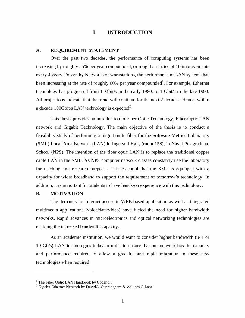
A. REQUIREMENT STATEMENT Over the past two decades, the performance of computing systems has been
increasing by roughly 55% per year compounded, or roughly a factor of 10 improvements
every 4 years. Driven by Networks of workstations, the performance of LAN systems has
been increasing at the rate of roughly 60% per year compounded1. For example, Ethernet
technology has progressed from 1 Mbit/s in the early 1980, to 1 Gbit/s in the late 1990.
All projections indicate that the trend will continue for the next 2 decades. Hence, within
a decade 100Gbit/s LAN technology is expected2
This thesis provides an introduction to Fiber Optic Technology, Fiber-Optic LAN
network and Gigabit Technology. The main objective of the thesis is to conduct a
feasibility study of performing a migration to fiber for the Software Metrics Laboratory
(SML) Local Area Network (LAN) in Ingersoll Hall, (room 158), in Naval Postgraduate
School (NPS). The intention of the fiber optic LAN is to replace the traditional copper
cable LAN in the SML. As NPS computer network classes constantly use the laboratory
for teaching and research purposes, it is essential that the SML is equipped with a
capacity for wider broadband to support the requirement of tomorrow’s technology. In
addition, it is important for students to have hands-on experience with this technology.
B. MOTIVATION The demands for Internet access to WEB based application as well as integrated
multimedia applications (voice/data/video) have fueled the need for higher bandwidth
networks. Rapid advances in microelectronics and optical networking technologies are
enabling the increased bandwidth capacity.
As an academic institution, we would want to consider higher bandwidth (ie 1 or
10 Gb/s) LAN technologies today in order to ensure that our network has the capacity
and performance required to allow a graceful and rapid migration to these new
technologies when required.
1 The Fiber Optic LAN Handbook by Codenoll 2 Gigabit Ethernet Network by DavidG. Cunningham & William G Lane
2
Until recently, the use of fiber as a cabling medium to the desktop has been
confined to special environments that required the unique properties of optical fiber such
as noise immunity, security, distance, high bandwidth demands (CAD/CAM, video
conferencing), and immunity to electrical interference. Several factors are changing this
situation:
• The accelerating deployment of fiber based Gigabit Ethernet (GbE) in the
LAN backbone.
• Uncertainty whether 10GbE will run on existing Category-5 twisted pair or
will require an upgrade to enhanced Category-5 wiring, Category-6 wiring, or
something even higher.
• The development of 1000Base-SX standard to support lower cost multimode
fiber runs in horizontal and shorter-length backbone applications.
Considering the needs for wider bandwidth, fiber will eventually be the dominant
cabling medium. The question is, when? To a certain extent, it depends on whether
copper can meet the demands of higher data rates with a standardized solution.
Deployment of Gigabit Ethernet as a backbone technology is rapidly gaining hold in
networks. Even though it’s unlikely that we will need gigabit speeds to the desktop any
time soon, many applications are outgrowing their 10 Mbps and 100 Mbps Ethernet
LANs. This prompted us to look for a migration path that will allow us to upgrade
networks incrementally, as needed. However, we should recognize this is not simply
tasks as upgrade brings about disruption to services and not to mention the usual high
cost involve in such an upgrade.
C. CHALLENGES
Today’s high-bandwidth applications and increasing reliance on Internet-based
communication are defining a new kind of network – one that needs to move large
amounts of data quickly, accessibly, and reliably. To meet these emerging needs, Local
Area Network (LAN) infrastructures are moving towards more robust, scalable networks.
While copper cable was initially used throughout LANs over the past 20 years, optical
fiber has proven itself to be a formidable alternative, offering users more bandwidth,
greater reliability and lower maintenance. Maintenance and downtime for Fber networks
3
are typically less than for copper-based networks. This is because they usually use less
electronics, thereby reducing network outages and downtown, are not subject to EMI/RFI
interference, and are generally easier to troubleshoot.3
Despite some obvious advantages of putting fiber into a LAN – greater bandwidth
capacity, security, network longevity, etc. – there are a number of misconceptions that
may be preventing users from making the switch from a copper-based solution to one
partially or entirely composed of fiber.
Common migration concerns:
• Fiber is too fragile to survive harsh conditions
• Fiber’s performance capabilities are unnecessary
• Fiber is more difficult to install than copper
• Switching from copper to fiber is expensive – and not worth the trouble
• An upgrade to fiber is too costly to implement
• Long-term copper users claim they don’t need fiber
However, such concerns fading as Fiber has proven to worth a second look with
new technology and improved standards. The advantage of the use of Fiber will
be discussed in the later section.
D. THESIS ORGANIZATION The thesis is organized as follows; Chapter II introduces the brief history and
background on Fiber Optic technology, focusing on fiber network topology, the physical
media used, and the various advantages and disadvantages of using a Fiber Optic LAN.
There will be a section that introduces the Gigabit Technology as this would be the
technology used in the proposed network. Chapter III presents the migration to fiber
feasibility study. It consists of a brief discussion on the concept of a Centralizing vis-à-
vis a Distributed Network, the proposed Fiber LAN design and a two-stage
implementation plan for the SML. The implementation plan would have hardware
specifications, software specifications and the estimated costing required. Finally, 3 Whitepaper prepared by FOLS dated January 2002 – The Truth About Fiber in Local Area Networks
4
Chapter IV concludes the thesis and primarily discusses future work and the areas of
further research regarding optical fiber LAN design and technologies.
5
II. BACKGROUND
A. HISTORY An important principle in physics became the theoretical foundation for optical
fiber communications: light in a glass medium can carry more information over longer
distances than electrical signals can carry in a copper or coaxial medium.
The first challenge undertaken by scientists was to develop a glass pure that one
percent of the light would be retained at the end of one kilometer (km), the existing
unrepeated transmission distance for copper-based telephone systems. In terms of
attenuation, this one-percent of light retention translated to 20 decibels per kilometer
(db/km) of glass material4.
Glass researchers all over the world worked on the challenge in the 1960s, but the
breakthrough came in 1970, when corning scientists Drs. Roberts Maurer, Donald Keck,
and Peter Schultz5 created a fiber with a measured attenuation of less than 20 dB per km.
It was the purest glass ever made.
Today, fiber’s optical performance is approaching the theoretical limits of silica-
based glass materials. This purity, combined with improved system electronics, enables
fiber to transmit digitalized light signals well beyond 100km (more than 60 miles)
without amplification.6
4 Web ProForum Tutorial by Corning – Fiber-Optic Technology 5 Web ProForum Tutorial by Corning – Fiber-Optic Technology 6 Web ProForum Tutorial by Corning – Fiber-Optic Technology
6
B. HOW FIBER WORKS The operation of an optical fiber is based on the principle of total internal
reflection. Light reflects (bounce back) or refracts (alters its direction while penetrating a
different medium), depending on the angle at which it strikes a surface.
This principle is at the heart of how optical fiber works. Light waves are guided
through the core of the optical fiber in much the same way that radio frequency (RF)
signals are guided through coaxial cable. The light waves are guided to the other end of
the fiber by being reflected within the core. Controlling the angle at which the light
waves are transmitted makes it possible to control how efficiently they reach the
destination. The composition of the cladding glass relative to the core glass determines
the fiber’s ability to reflect light. The difference in the index of refraction of the core and
the cladding causes most of the transmitted light to bounce off the cladding glass and stay
within the core. In this way, the fiber core acts as a waveguide for the transmitted light.
C FIBER OPTIC TECHNOLOGY A fiber-optic system can generally be seen as a system with three main
components, a transmitter, a transmission medium, and a receiver. It is similar to the
copper wire system that fiber-optics is replacing. The difference is that fiber-optics uses
light pulses to transmit information down fiber lines instead of using electronic pulses to
transmit information down copper lines. Looking at the three main components in the
fiber-optic chain, will provide a better understanding of how the system works in
conjunction with wire based systems.
At the head end of the chain is the transmitter. This is the place of origin for
information coming on to fiber-optic lines. The transmitter accepts coded electronic pulse
information coming from copper wire. It then processes and translates that information
into equivalently coded light pulses. A light-emitting diode (LED) or an injection-laser
diode (ILD) can be used for generating the light pulses. Using a lens, the light pulses are
funneled into the fiber-optic medium where they transmit down the line.
Light pulses move easily down the fiber-optic line because of a principle known as total
internal reflection, as explained earlier.
7
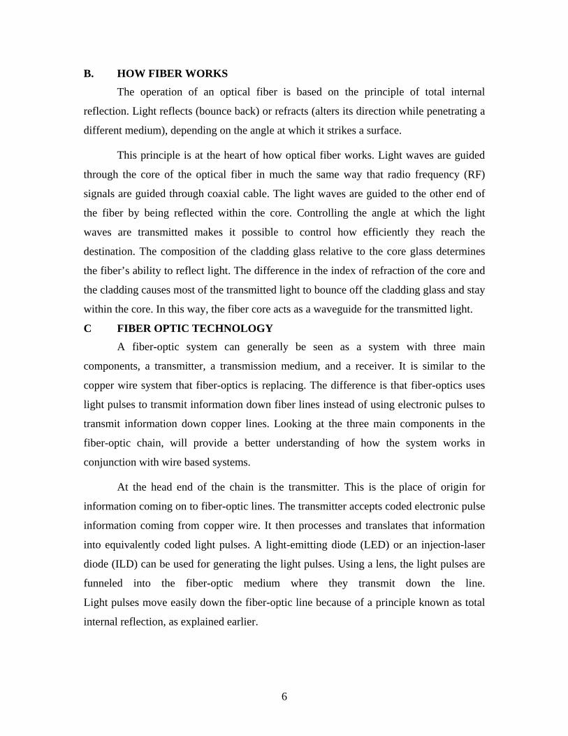
There are generally five elements that make up the construction of a fiber-optic
strand, or cable: the optic core, optic cladding, a buffer material, a strength material and
the outer jacket (Fig. 1). The optic core is the light carrying element at the center of the
optical fiber. It is commonly made from a combination of silica and germania.
Surrounding the core is the optic cladding made of ultra-pure silica. It is this combination
that makes the principle of total internal reflection possible. The difference in materials
used in the making the core and the cladding create an extremely reflective surface at the
point at which they interface. Light pulses entering the fiber core reflect off the
core/cladding interface and thus remain within the core as they move down the line.
Figure 1: Cut Away of a Fiber-Optic Cable (ref: Fiber Optic Basic by Terry Macy)
Surrounding the cladding is a buffer material used to help shield the core and
cladding from damage. A strength material surrounds the buffer, preventing stretch
problems when the fiber cable is being pulled. The outer jacket is added to protect against
abrasion, solvents, and other contaminants.
Once the light pulses reach their destination they are channeled into the optical
receiver. The basic purpose of an optical receiver is to detect the received light incident
8
on it and to convert it to an electrical signal containing the information impressed on the
light at the transmitting end. In other words, the coded light pulse information is
translated back into its original state as coded electronic information. The electronic
information is then ready for input into electronic based communication devices, such as
a computer, telephone, or TV.
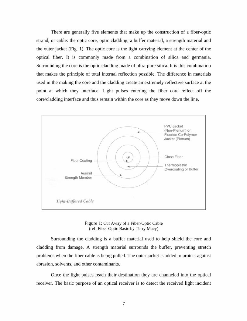
1. Single-Mode and Multimode Fibers There are two general categories of optical fiber; single-mode and multimode.
Figure 2: Single-Mode and Multimode Fiber
Multimode fiber was the first type to be commercialized. It has much larger core
than single-mode fiber, allowing hundreds of modes of light to propagate through the
fiber simultaneously. Additionally, the large core diameter of multimode fiber facilitates
the use of lower cost optical transmitters (such as light emitting diodes [LEDs] or vertical
cavity surface emitting lasers [VCSELs]) and connectors.
Single-mode fiber, on the other hand, has a much smaller core that allows only
one mode of light at a time to propagate through the core. While it might appear that a
multimode fiber has higher capacity, in fact the opposite is true. Single-mode fibers are
designed to maintain spatial and spectral integrity of each optical signal over long
distances, allowing information to be transmitted at a higher rate.
Its tremendous information carrying capacity and low intrinsic loss have made
single-mode fiber the ideal transmission medium for a multitude of applications. Single-
mode fiber is typically used for longer distance and higher bandwidth applications.
Multimode fiber is used primarily in systems with short transmission distances (under
2km), such as premised communication and Local Area Network (LAN).
9
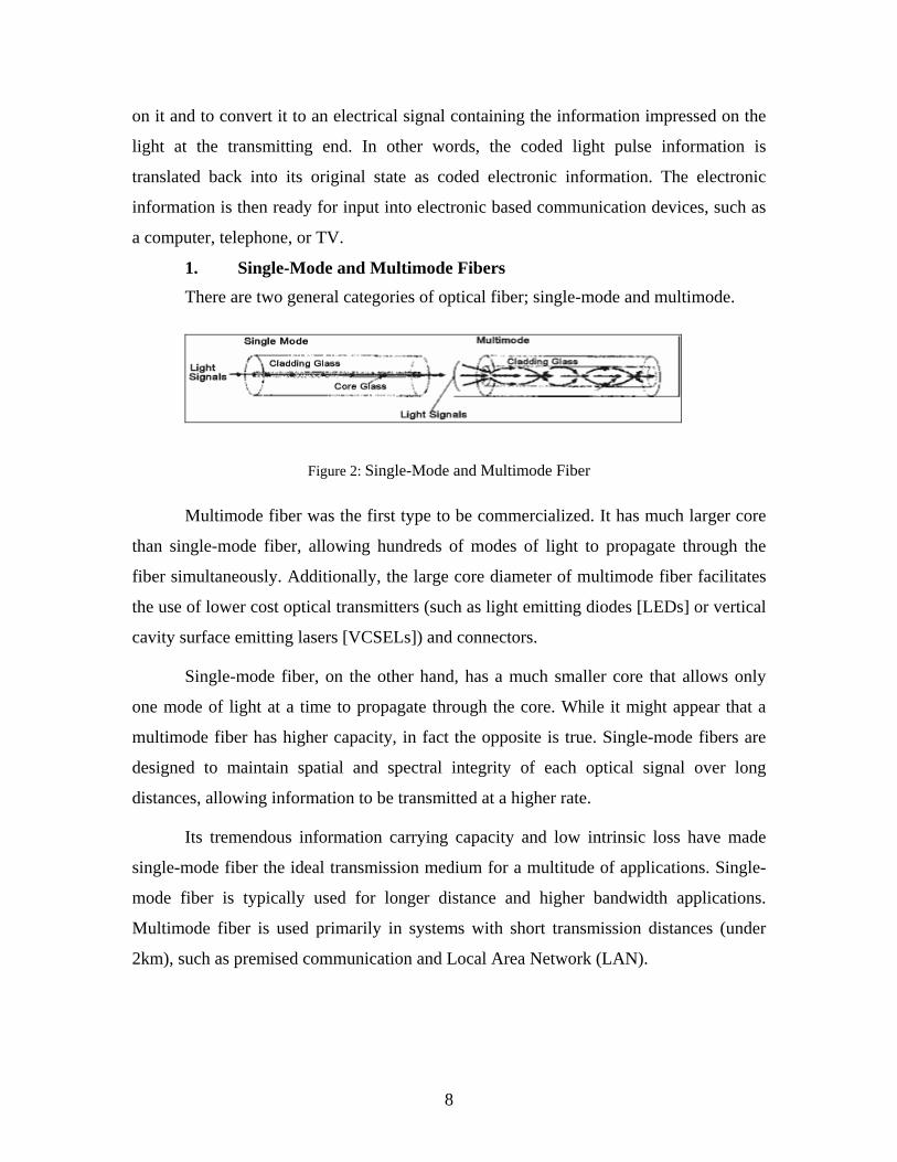
2. Optical Fiber Sizes The international standard for outer cladding diameter of most single-mode
optical fibers is 125 microns (µm) for the glass and 245 µm for the coating. This standard
is important because it ensures compatibility among connectors, splices, and tools used
throughout the industry.
Standard single mode fibers are manufactured with small core size, approximately
8 to 10 µm in diameter. Multimode fibers have core sizes of 50 to 62.5 µm in diameter.7
Figure 3: Optical Fiber Sizes
3. Modulating the Light Source Fiber optic communications systems offer a unique set of solutions (and problems)
to the task of moving mountains of information from one location to another. However,
like any form of communication, the signal to be transmitted must be encoded onto the
carrier at the source (transmitter) and decoded from the carrier at the destination
(receiver).
When the carrier is a light wave, signal encoding is physically done either through
direct modulation or external modulation of the light source. For example, varying the
current of a laser diode (and therefore its light output) is a form of direct modulation.
7 Fiber Optic Basic by Terry Macy
10
The type of modulation and encoding used in a fiber optic transmitter depends on
a number of factors, but some light sources are better suited for certain schemes than
others. For instance, the broad spectral output of light-emitting diodes (LEDs) precludes
them from modulation techniques that require a stable monochromatic wave-front such as
phase and frequency modulation. For LED fiber optic transmitters, intensity modulation
is the best direct encoding method. This is also true for low-coherence diode lasers.
Nevertheless, frequency or phase modulation can be achieved indirectly with these light
sources if the modulation is first performed on an electronic subcarrier, and the subcarrier
is then used to modulate the intensity of the source.
The compact, solid-state structure of LEDs and diode lasers, as well as their
compatibility with direct intensity modulation, has made them overwhelmingly
successful for fiber optic communications (particularly diode lasers). And the invention
of stable, tunable, single- frequency diode lasers such as distributed-feedback (DFB)
lasers and distributed-Bragg- reflector (DBR) cavities has stimulated the growth of
coherent fiber-optic communications systems for external modulation of phase or
frequency8.
Coherent communications systems actually require at least two single-frequency
lasers, one at the transmitter and one at the receiver. With this arrangement, modulated
light from the transmitting laser can be heterodyned (or homodyned) with the brighter
light from the receiver's laser, which is called a local oscillator. The result is a
hundredfold improvement in receiver sensitivity over simpler systems that detect the light
signal directly (direct detection).
Modulation schemes for coherent communications systems include amplitude
shift keying, frequency shift keying, phase shift keying (PSK), and differential phase shift
keying. Homodyne PSK offers the highest sensitivity of any coherent detection system.
Another big advantage of coherent optical communications systems is that they
allow narrower channel spacing for wavelength-division multiplexing (WDM).
Multiplexing refers to any of several techniques used to pack more information on a
8 Fiber-Optic Technology by The International Engineering Consortium
11
single fiber by simultaneously transmitting several signals over the same fiber. To avoid
gibberish at the receiving end, each signal is uniquely tagged in a way that the receiver
can recognize. WDM accomplishes this by delivering each signal on a slightly different
laser frequency that is then optically filtered by the receiver.
Besides WDM, two other important kinds of multiplexing are time-division
multiplexing (TDM) and frequency-division multiplexing (FDM). TDM segregates
samples of each signal into separate time slots that the receiver can clock off individually.
With FDM, each signal is carried on a separate sub-carrier frequency that can be
electronically filtered out by the receiver.
4. Semiconductors Sources and Detectors In addition to the demands of modulation and encoding, light signals often must
travel many miles of glass before they reach the receiver. If the signal is to maintain
detectable strength and fidelity over those distances, the glass must have low loss (scatter,
absorption, and so forth) and low dispersion at the wavelength of the light source. This
turns out to be an impossible task for most fiber optic installations because step-index
silica fiber has zero dispersion at a wavelength of 1.3um and minimal loss (0.16 dB/km)
at 1.55um.
However, fiber loss and dispersion are of little concern in applications such as
intra-office communications and local-area networks. Here, distances are short and data
rates are usually low, allowing low-cost communications systems equipped with
aluminum gallium arsenide LEDs, multimode fiber, and silicon photo-detectors to be
used. The LEDs of these so-called first generation systems are either surface or edge
emitting and emit light in the 0.87um region where fiber dispersion and loss are both high.
This wavelength also happens to be well suited for silicon PIN and avalanche
photodiodes.
For higher data rates or longer distances, sources and detectors must operate near
the 1.3 or 1.55um regions which are defined as second and third generation fiber optic
systems, respectively. However, such technologies will not be discussed here as we will
only be dealing with short-length local-area network.
12
D. NETWORK TOPOLOGY
1. Fiber Optic Design Considerations
Before fiber optic networks can be constructed, they must be properly designed
and, once constructed, they must be managed. Efficiencies in these processes translate
into lower cost layout and construction, more productive system migration and field
operations, lower optical loss budget, by bringing fiber to the desk.
The fiber optic network layout design plays an important role in error-free system
reliability. Choice of the proper type of network layout depends on the type of process
controlled, the possible need for expansion, and the degree of failure immunity desired–
all of which must be balanced with cost considerations.
a. Basic Layout Network Designs
The commonly known Network Designs or configurations are bus, star,
and collapsed backbone. For each type, the purpose of the network is to provide
communication between the devices, or nodes, in the system. "Node" is a general term
that refers to a PC, switch, router, programmable logic controller (PLC), remote
input/output (I/O) drop, distributed control system (DCS) controller, or any
communication device. Each of the three network types has advantages and
disadvantages, depending on the application. However, the most common used in today
network system is the Star network topology. Star topology can easily be implemented
with fiber or copper, or a combination of both. The network is also simpler to maintain
and troubleshoot, and it is far more open and adheres to 802.3 standards. The next section
will elaborate further on the Star network topology.
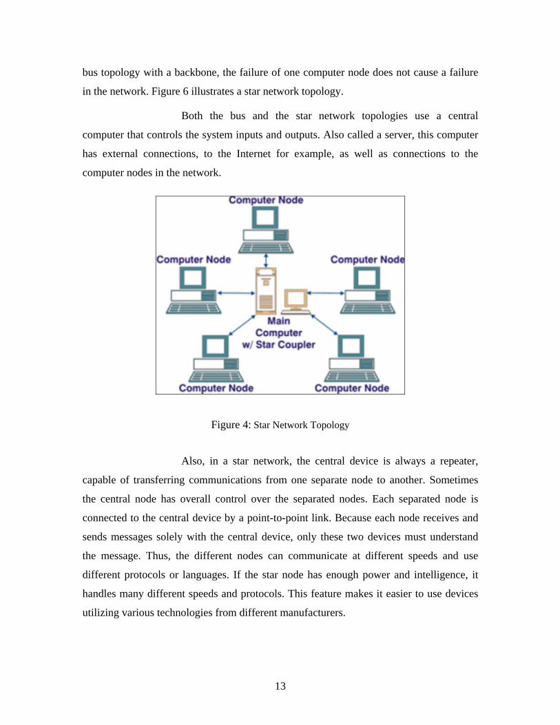
(1) Star Network. Star networks incorporate multi-port star
couplers in to achieve the topology. Once again, a main controlling computer or
computer server interconnects with all the other computers in the network. As with the
13
bus topology with a backbone, the failure of one computer node does not cause a failure
in the network. Figure 6 illustrates a star network topology.
Both the bus and the star network topologies use a central
computer that controls the system inputs and outputs. Also called a server, this computer
has external connections, to the Internet for example, as well as connections to the
computer nodes in the network.
Figure 4: Star Network Topology
Also, in a star network, the central device is always a repeater,
capable of transferring communications from one separate node to another. Sometimes
the central node has overall control over the separated nodes. Each separated node is
connected to the central device by a point-to-point link. Because each node receives and
sends messages solely with the central device, only these two devices must understand
the message. Thus, the different nodes can communicate at different speeds and use
different protocols or languages. If the star node has enough power and intelligence, it
handles many different speeds and protocols. This feature makes it easier to use devices
utilizing various technologies from different manufacturers.
14
Furthermore, the central node is usually a hub or a multiplexer that
utilizes repeaters to forward data. Some repeaters can interconnect cable segments using
different physical media such as coaxial cables and fiber optic cables. With a star
topology, the future growth is easy. The expansion the network is easily done by adding
another concentrator. The Star topology is generally the preferred network configuration
today; however, the limitation of the Star topology would be it lacks of media
redundancy. Some of the advantages and disadvantages of a Star topology are as follows;
a. Advantages of a Star Topology
• Easy to install and wire.
• No disruptions to the network then connecting or removing
devices.
• Easy to detect faults and to remove parts.
b. Disadvantages of a Star Topology
• Requires more cable length than a linear topology.
• If the hub or concentrator fails, nodes attached are disabled.
• More expensive than linear bus topologies because of the cost
of the concentrators.
b. Achieving High Reliability In order to achieve high reliability network, many hybrid variations on the
basic network types are possible, usually incorporating the star in one form or another. If
a cable is damaged in a physical star, communication stops only with the node served by
the damaged cable; the other nodes continue to operate. Thus Star topology generally
offers a high reliability as a network configuration. It must be borne in mind, however,
that if the star (center) node itself fails, all control is lost, which rarely happens.
E. FIBER-OPTIC ADVANTAGES AND DISADVANTAGE There are several advantages that have been established with the development and
implementation of fiber-optic cable systems. However, this thesis will only look at the
advantages in using Fiber-Optic in the horizontal.
15
• Fiber’s relatively error-free transmission over longer distances. With
longer link distances for cabling in the horizontal, network designers also have more
flexibility in planning their networks, and are able to take advantage of new architectures.
• Fiber’s ability to support higher data rates. Fiber’s high bandwidth takes
advantage of existing applications and emerging high-speed network interfaces and
protocols such as Gigabit Ethernet.
• Fiber’s long term economic benefits. Over the lifetime of the network,
optical fiber is typically a more economically viable choice than copper. For example,
fiber’s superior reliability reduces operating costs by minimizing network outages.
Similarly, fiber’s higher bandwidth can produce considerable savings by eliminating the
need to pull new cable when the network is upgraded to support higher bandwidth
applications. However, having said that, the installation of costs of copper is still cheaper,
both in cable cost and labor.
• Fiber is immune to EMI/RFI signals. Optical fiber carries light rather than
electricity, so it is not affected by electromagnetic interference from power (sub-
kilohertz), radio (kilohertz to megahertz), or microwave (gigahertz) sources. Interfering
signals from these sources can couple into copper cables creating sporadic problems that
are difficult to troubleshoot and repair. Further, radiated emissions and susceptibility to
external interference are almost entirely eliminated simply by the inherent design of
optical cables.
• Fiber is immune to crosstalk. Crosstalk occurs when unwanted signals are
coupled between copper conductors. Signals cannot couple between fibers in a cable, thus
eliminating crosstalk.
• Fiber systems are easier to test9. Even with higher data rates, fiber test
requirements have not increased in complexity. For copper cabling, however, there are
now more than 20 specified parameters (see attachment 2) for Gigabit Ethernet as
opposed to two for optical fiber (attenuation and bandwidth).
9 Fiber-Optic Technology – by The International Engineering Consortium
16
• Fiber provides greater reliability and equipment safety. Unlike copper
facilities, all dielectric fiber cabling systems do not conduct lightning strikes or electrical
currents that can damage sensitive electronic transmission equipment.
A possible disadvantage of the fiber-optic system is it's incompatibility with the
electronic hardware systems. This inability to interconnect requires that current
communication hardware systems be retrofitted to the fiber-optic networks. Much of the
speed that is gained through optical fiber transmission can be inhibited at the conversion
points of a fiber-optic chain. When a portion of the chain experiences heavy use,
information becomes jammed in a bottleneck at the points where conversion to, or from,
electronic signals is taking place. Bottlenecks like this should become less frequent as
microprocessors become more efficient and fiber-optics reach closer to a direct electronic
hardware interface with the improvement of media converters.
F. GIGABIT TECHNOLOGY 87% of all installed network connections are Ethernet10. This is primarily due to
the fact that industry standards for Ethernet, over 25 years old, have progressed along
with networking requirements. This progression of industry standards provides a clear
and easy migration path as bandwidth demands increases.
Gigabit Ethernet has evolved from the original industry standards for 10Mbps
Ethernet (10Base-T) and 100Mbps Fast Ethernet (100Base-TX and 100Base-FX). In June
1998When IEEE approved Gigabit Ethernet over Fiber-optic cable.
Gigabit Ethernet began to be used along network backbone and in network servers
via GbE adapters to remove traffic bottlenecks in area of congestion. However, as
Internet-based activities increased, Gigabit links are being deployed from workgroup to
data center and to desktop.
The Gigabit Ethernet standard is compatible with the original Ethernet frame
format, and nothing more. It supports full-duplex as well as half duplex modes of
operation. However, in enabling Gigabit operation, the CSMA/CD access method is
modified to allow a transmitter to extend its carrier and to allow multiple packets to be
10 According to International Data Corporation, IDC 2000.
17
transmitted in a burst. Therefore, Gigabit Ethernet operation in half-duplex CSMA/CD
mode requires the presence of carrier or collision events to be signaled to the CSMA/CD
MAC. In full-duplex mode (switch-based operation) the CSMA/CDMAC is not used, and
so carrier sense and collision detect are not required. The standard uses physical signaling
technology used in Fiber Channel to support Gigabit rates over optical fibers.
1. Physical Layer The Physical Layer of Gigabit Ethernet uses a mixture of proven technologies
from the original Ethernet and the ANSI X3T11 Fiber Channel Specification. Gigabit
Ethernet is able to support 4 physical media types. These standards is defined in 802.3z
(1000Base-X) and 802.3ab (1000Base-T).11
a 1000Base-X The 1000Base-X standard is based on the Fiber Channel Physical Layer.
Fiber Channel is an interconnection technology for connecting workstations,
supercomputers, storage devices and peripherals. Fiber Channel has a 4-layer architecture.
The lowest two layers FC-0 (Interface and media) and FC-1 (Encode/Decode) are used in
Gigabit Ethernet. Since Fiber Channel is a proven technology, re-using it will greatly
reduce the Gigabit Ethernet standard development time12.
Three types of media are include in the 1000Base-X standards
• 1000Base-SX 850 nm laser on multi mode fiber.
• 1000Base-LX 1300 nm laser on single mode and multi mode fiber.
• 1000Base-CX Short haul copper "twinax" STP (Shielded Twisted
Pair) cable
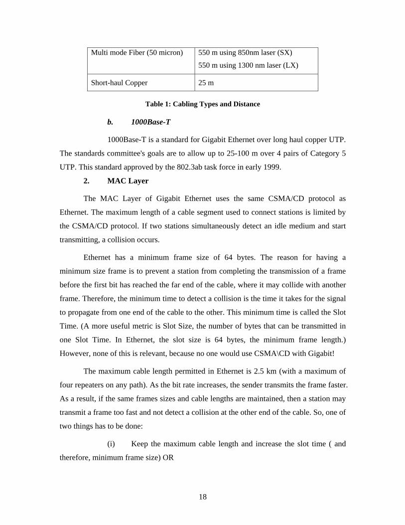
The cabling distances to be supported are given in Table
Cable Type Distance
Single-mode Fiber (9 micron) 3000 m using 1300 nm laser (LX)
Multi mode Fiber (62.5 micron)
300 m using 850 nm laser (SX)
550 m using 1300 nm laser (LX)
11 Gigabit Ethernet Networking – by David G. Cunningham & William G. Lane 12 Gigabit Ethernet Networking – by David G. Cunningham & William G. Lane
18
Multi mode Fiber (50 micron)
550 m using 850nm laser (SX)
550 m using 1300 nm laser (LX)
Short-haul Copper 25 m
Table 1: Cabling Types and Distance
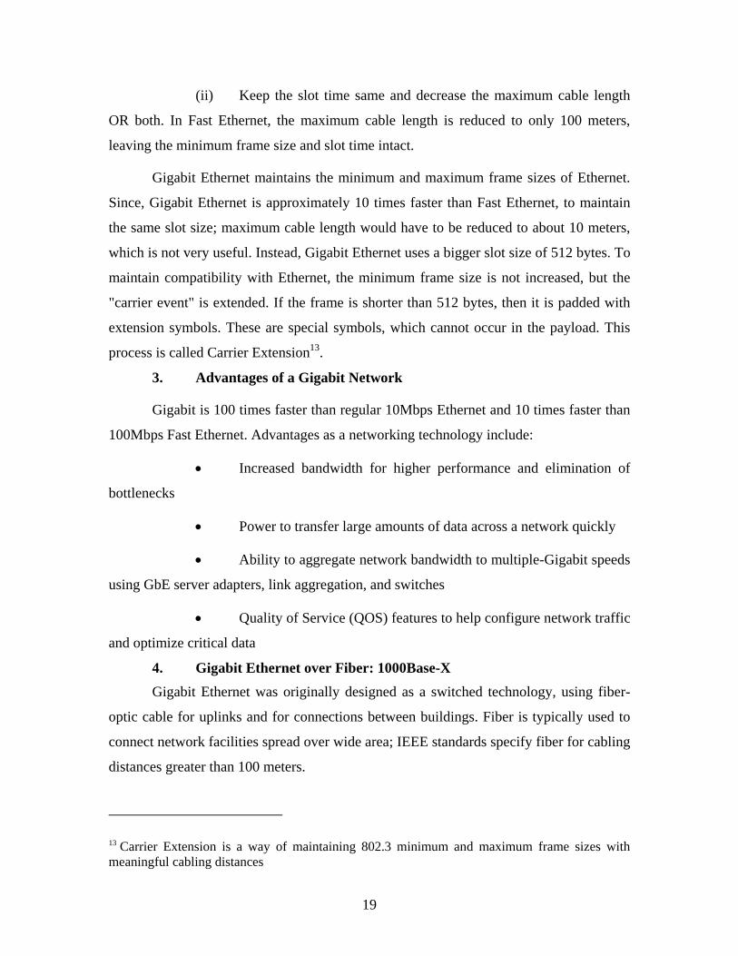
b. 1000Base-T
1000Base-T is a standard for Gigabit Ethernet over long haul copper UTP.
The standards committee's goals are to allow up to 25-100 m over 4 pairs of Category 5
UTP. This standard approved by the 802.3ab task force in early 1999.
2. MAC Layer
The MAC Layer of Gigabit Ethernet uses the same CSMA/CD protocol as
Ethernet. The maximum length of a cable segment used to connect stations is limited by
the CSMA/CD protocol. If two stations simultaneously detect an idle medium and start
transmitting, a collision occurs.
Ethernet has a minimum frame size of 64 bytes. The reason for having a
minimum size frame is to prevent a station from completing the transmission of a frame
before the first bit has reached the far end of the cable, where it may collide with another
frame. Therefore, the minimum time to detect a collision is the time it takes for the signal
to propagate from one end of the cable to the other. This minimum time is called the Slot
Time. (A more useful metric is Slot Size, the number of bytes that can be transmitted in
one Slot Time. In Ethernet, the slot size is 64 bytes, the minimum frame length.)
However, none of this is relevant, because no one would use CSMA\CD with Gigabit!
The maximum cable length permitted in Ethernet is 2.5 km (with a maximum of
four repeaters on any path). As the bit rate increases, the sender transmits the frame faster.
As a result, if the same frames sizes and cable lengths are maintained, then a station may
transmit a frame too fast and not detect a collision at the other end of the cable. So, one of
two things has to be done:
(i) Keep the maximum cable length and increase the slot time ( and
therefore, minimum frame size) OR
19
(ii) Keep the slot time same and decrease the maximum cable length
OR both. In Fast Ethernet, the maximum cable length is reduced to only 100 meters,
leaving the minimum frame size and slot time intact.
Gigabit Ethernet maintains the minimum and maximum frame sizes of Ethernet.
Since, Gigabit Ethernet is approximately 10 times faster than Fast Ethernet, to maintain
the same slot size; maximum cable length would have to be reduced to about 10 meters,
which is not very useful. Instead, Gigabit Ethernet uses a bigger slot size of 512 bytes. To
maintain compatibility with Ethernet, the minimum frame size is not increased, but the
"carrier event" is extended. If the frame is shorter than 512 bytes, then it is padded with
extension symbols. These are special symbols, which cannot occur in the payload. This
process is called Carrier Extension13.
3. Advantages of a Gigabit Network
Gigabit is 100 times faster than regular 10Mbps Ethernet and 10 times faster than
100Mbps Fast Ethernet. Advantages as a networking technology include:
• Increased bandwidth for higher performance and elimination of
bottlenecks
• Power to transfer large amounts of data across a network quickly
• Ability to aggregate network bandwidth to multiple-Gigabit speeds
using GbE server adapters, link aggregation, and switches
• Quality of Service (QOS) features to help configure network traffic
and optimize critical data
4. Gigabit Ethernet over Fiber: 1000Base-X Gigabit Ethernet was originally designed as a switched technology, using fiber-
optic cable for uplinks and for connections between buildings. Fiber is typically used to
connect network facilities spread over wide area; IEEE standards specify fiber for cabling
distances greater than 100 meters.
13 Carrier Extension is a way of maintaining 802.3 minimum and maximum frame sizes with meaningful cabling distances
20
Even when long distances are not involved, environment can play a part in the
choice of fiber over copper. For example, fiber is less susceptible to the electro-magnetic
interference that can affect data transmission over copper.
a. Special Considerations Security Fiber may be the best option for intra-building applications
and other situations where cabling runs must be left exposed. Fiber-optic cable cannot be
spliced except under clean-room conditions, making it nearly impossible for a hacker to
tap into the cable.
Related Expense Installation of fiber-optic cable can be difficult, and
therefore more expensive than Cat-5 copper cable. The termination and connectors, as
well as optical receivers (switch ports), are costly even thought cost of such equipment
have reduced significantly.
Desktop Deployment It appears that unless security or interference are
concerns, deploying of fiber to the desktop may be still costly as switch ports need to be
replaced. Also current fiber technology is not capable of powering network-attached
devices at the desktop level.
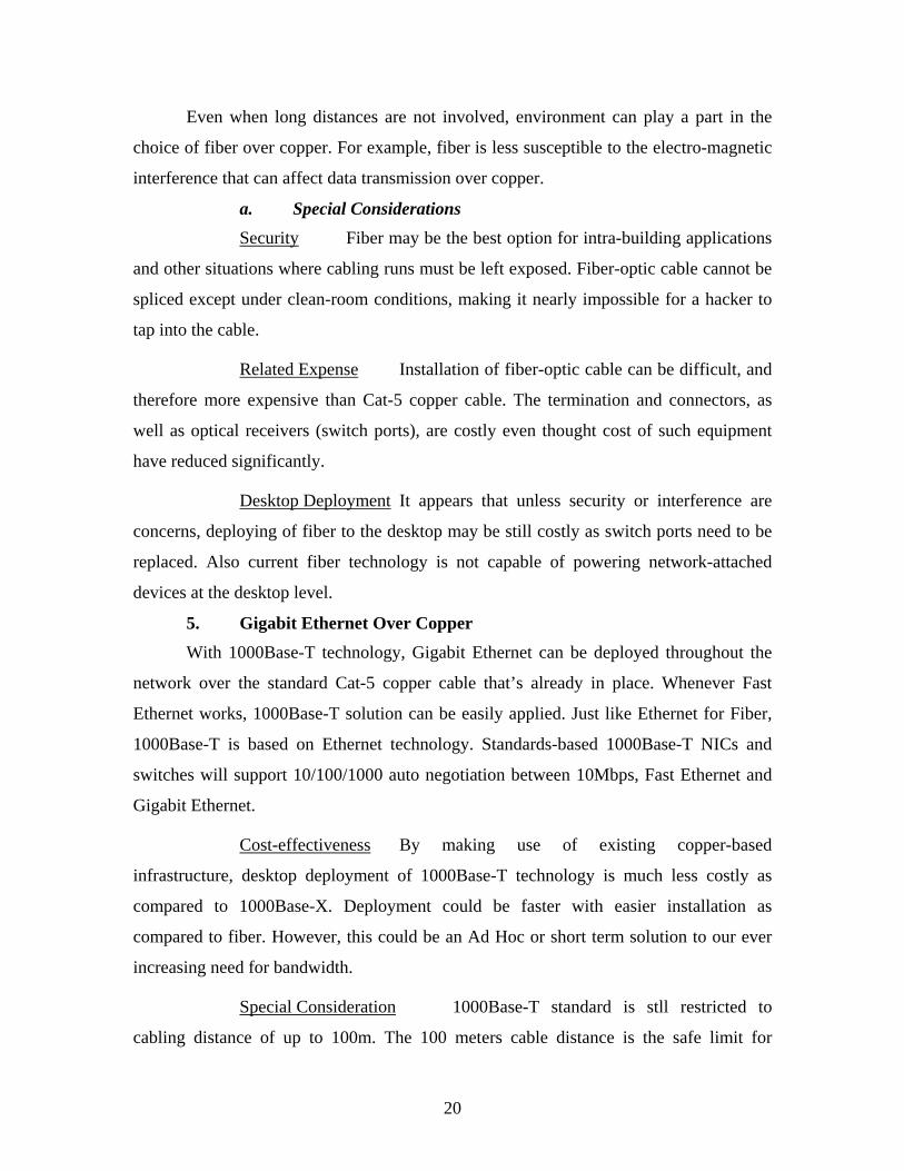
5. Gigabit Ethernet Over Copper With 1000Base-T technology, Gigabit Ethernet can be deployed throughout the
network over the standard Cat-5 copper cable that’s already in place. Whenever Fast
Ethernet works, 1000Base-T solution can be easily applied. Just like Ethernet for Fiber,
1000Base-T is based on Ethernet technology. Standards-based 1000Base-T NICs and
switches will support 10/100/1000 auto negotiation between 10Mbps, Fast Ethernet and
Gigabit Ethernet.
Cost-effectiveness By making use of existing copper-based
infrastructure, desktop deployment of 1000Base-T technology is much less costly as
compared to 1000Base-X. Deployment could be faster with easier installation as
compared to fiber. However, this could be an Ad Hoc or short term solution to our ever
increasing need for bandwidth.
Special Consideration 1000Base-T standard is stll restricted to
cabling distance of up to 100m. The 100 meters cable distance is the safe limit for
21
reliable transmission. 1000Base-T physical layer standard provides 1Gbps Ethernet signal
transmission over four pairs of Cat 5 UTP cable. But by using more sophisticated 5-level
coding along with the four wire pairs, it is able to transmit much more data. Essentially, it
transmits at 125Mbaud, the same symbol rate as Fast Ethernet, except that it is done
simultaneously (full-duplex). Other consideration relating to 1000Base-T implementation
would be Far-end crosstalk14 and return loss15.
14 Far-End Cross Talk (FEXT) is the noise on a wire pair at the end from the transmitter caused by signal leakage from adjoining wire. 15 Return loss defines the amount of signal energy that is reflected back toward the transmitter due to impedance mismatches in the link.

22
THIS PAGE INTENTIONALLY LEFT BLANK
23
III. MIGRATING TO FIBER FEASIBILITY STUDY
The goal of this chapter is perform a compatibility and feasibility study of
implementing a high speed fiber optic local area network (LAN) in the Software Metrics
Laboratory in Ingersoll 158. In order to stay abreast of the latest advances in networking
technologies, NPS computer network and software reliability classes, namely IS3502,
IS3020 and SW4581 require a laboratory that is equipped high speed networking
technologies, Gigabit Ethernet over fiber. The primary objective of the SML laboratory is
to provide the necessary technology support facilities to students attending any computer
network classes conducted at NPS. It also serves to assist the staff and students in their
research work and thesis projects specializing in high speed network design. The
laboratory resources are available for usage by any authorized staff and at all times.
The goal of this research is to study the feasibility of migration from copper to
fiber and retaining the original requirements of the SML. The following list provides the
principal considerations for the SML’s fiber optic LAN migration:
• Cost justification. This paper must show the cost advantage broadly in
migrating to fiber over copper for the medium to long term.
• Minimize disruptions to the use of SML for lessons. The constraints of
the project required the migration to fiber design to be broken in stages as to prevent
disruption to the year long use of the lab for classes.
• Connection to NPS backbone LAN. The study should propose a
compatible connection to the to NPS fiber backbone.
• Security. The security considerations were established based on the
existing NPS security guidelines and requirements for wired LANs. The security for
Internet connectivity is to be managed by the NPS network security administrator.
• Scalability. The choice of fiber LAN hardware and design should be
scalable as much as possible given the possible future expansion of the Fiber LAN
network within the laboratory.
24
A. COST JUSITIFICATION Historically, choosing between fiber-optic cabling and unshielded twisted pair
(UTP) copper cabling for the horizontal infrastructure meant choosing between
performance (favoring fiber) and cost (favoring copper). Over the years, the distinctions
between the two cabling technologies have lessened: Copper cabling, once perceived as a
technological “dead end” at 100 MHz, now seems destined for continued growth in its
bandwidth capacity from today’s category 5e through category 6 and 7. Likewise, new
technologies in fiber have brought the costs of passive fiber components nearly into line
with those of copper.
However, all of this notwithstanding, the prices of active fiber-optic components,
particularly fiber NICs and switch ports, have traditionally been considerably higher than
those of copper. Indeed, the difference has historically ranged from a few hundred dollars
per port to more than a thousand dollars per port for high-end Gigabit Ethernet devices.
The perceived major advantage in fiber’s performance is overshadowed by its prohibitive
costs previously. With advancement in Fiber Technology, the cost of such components
has reduced significantly and the disparity has narrowed16.
The installation cost of a fiber-based system is usually within 20% of a copper-
based system17. Looking from a cost point of view, Fiber is not an attractive upgrading
option. However, this is not the case if we are looking at the network life cycle cost. Fiber
user can enjoy the long term benefits of fiber cable – higher bandwidth, easy scalability,
and lower maintenance over a network life of 10-15 years18. Fiber is better “future-proof”
as fiber technology is neutral; any number of protocols can be used. The network speed
can be upgraded at a later time simply by replacing the NIC. With the ever increasing
needs for bandwidth, the next speed upgrade could be soon and copper cable is not able
to support 10 Gigabit technologies.
16 Article from Media for Lightwave by Dave Cook – When installing fiber to Desktop makes sense. 17 Article from Media for Lightwave by Dave Cook – When installing fiber to Desktop makes sense. 18 Optical Network by Kunachelvan Shanmugalingam
25
This disparity in costs can be further attributed to the erroneous presumption that
fiber-optic networks should be designed exactly like copper infrastructures 19 . Such
presumption of carrying over all the extra design constraints of copper networks to a
fiber-optic design results in higher fiber-optic prices. However, designing fiber-optic
networks based upon the design characteristics of fiber often derive substantial savings.
Before proceeding to the proposed fiber-network in SML, we should examine the
NPS network configuration for the purpose of compatibility.
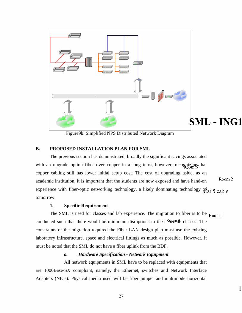
1. NPS Existing Network Configuration The NPS computer network is made up of a large number of small LAN's spread
all over the campus. Thus, the NPS uses a fiber optic-cable as a transmission medium
(backbone) that allows a higher bandwidth and lower delay to interconnect its main
buildings to each other (intranet) and to facilitate their communications with the outside
world via routers (internet). In addition, the NPS has installed Gigabit Ethernet network
technology. The fiber backbone is connected to 2xBigIron 8000 layer-3 switch (10
Gigabit ready) at the Campus Distribution Frame (CDF) located in the Computer Center
located at Ingorsol building. The fiber network is distributed to the various building by
directly linked to core Gigabit Ethernet switches using BigIron 4000 that are usually
located on the first deck of each main building (Building Distribution Frame). The data
transmission speed of this switch is rated at 1Gbps, which utilizes the single mode fiber
optics. Furthermore, within each deck in a main building, the core Gigabit Ethernet
switch is connected to BigIron 4000 series Ethernet switches (running at 155 Mbps) via
multimode fiber optic cable. Those switches are combined in two stacks. Each stack
consists of four modules that manage a total of 192 ports. This patch panel is connected
to each wall plate via Cat 5 that interconnects either individual workstations or hubs that
form small LANs. Moreover, NPS uses many types of servers to support its educational
and administrative functions. For instance, e-mail servers are dedicated to controlling
incoming and outgoing mail messages while web-servers are employed to support the
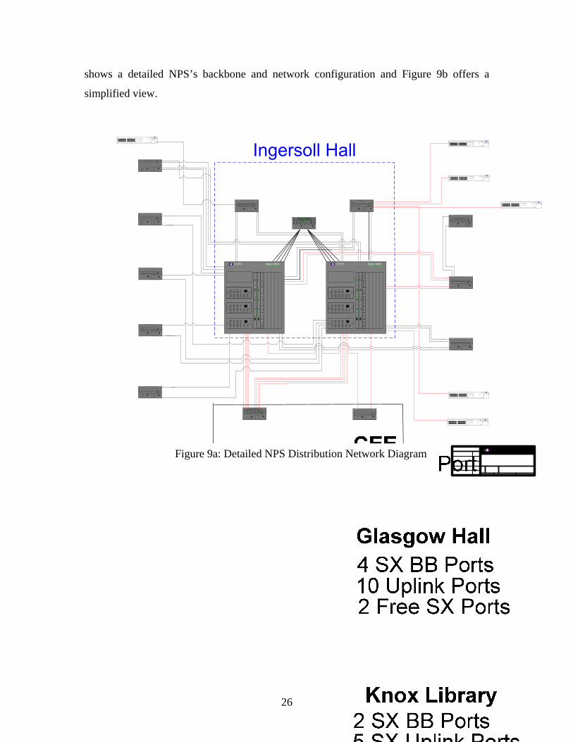
Internet and multipurpose servers are used to support NPS user accounts needs. Figure 9a
19 A Cost Effective Migration Path for Fiber in the Horizontal – by FOLS dated February 2000
26
shows a detailed NPS’s backbone and network configuration and Figure 9b offers a
simplified view.
BigIron 4000FOUNDRYNETWO RKS
BigIron 4000FOUNDRYNETWO RKS
BigIron 4000FOUNDRYNETWO RKS
BigIron 4000FOUNDRYNETWO RKS
BigIron 4000FOUNDRYNETWO RKS
BigIron 4000FOUNDRYNETWO RKS
BigIron 4000FOUNDRYNETWO RKS
BigIron 4000FOUNDRYNETWO RKS
BigIron 4000FOUNDRYNETWO RKS
BigIron 4000FOUNDRYNETWO RKS
BigIron 4000FOUNDRYNETWO RKS
BigIron 4000FOUNDRYNETWO RKS
BigIron 4000FOUNDRYNETWO RKS
1 2 3 4 5 6 7 8 Ac tive Console
Pwr
B8
GMR
Mgm
t II
+ Gi ga
bi tL ink
Ac tivi ty
Link
Activ ity
Link
Activi ty
L ink
Ac tivi ty
1 2 3 4 5 6 7 8 Ac tive Console
Pwr
B8
GMR
Mgm
t II
+ Gi ga
bi tL ink
Ac tivi ty
Link
Activ ity
Link
Activi ty
L ink
Ac tivi ty
1 2 3 4 5 6 7 8 Ac tive Console
Pwr
B8
GMR
Mgm
t II
+ Gi ga
bi tL ink
Ac tivi ty
Link
Activ ity
Link
Activi ty
L ink
Ac tivi ty
1 2 3 4 5 6 7 8 Ac tive Console
Pwr
B8
GMR
Mgm
t II
+ Gi ga
bi tL ink
Ac tivi ty
Link
Activ ity
Link
Activi ty
L ink
Ac tivi ty
8-por
t
G igabi
t
1 2 3 4 5 6 7 8
B8G
Link
Acti vity
Link
Activ ity
L ink
Ac ti vi ty
Link
Acti vity
1 2 3 4 5 6 7 8 Ac tive Console
Pwr
B8
GMR
Mgm
t II
+ Gi ga
bi t
L ink
Ac ti vi ty
Link
Activ ity
Link
Acti vi ty
L ink
Ac ti vi ty
1 2 3 4 5 6 7 8 Ac tive Console
Pwr
B8
GMR
Mgm
t II
+ Gi ga
bi t
L ink
Ac ti vi ty
Link
Activ ity
Link
Acti vi ty
L ink
Ac ti vi ty
1 2 3 4 5 6 7 8 Active Console
Pwr
B8
GMR
Mgm
t I I
+ Gi ga
bi tLink
Activ ity
L ink
Activi ty
Link
Activ ity
Link
Activi ty
1 2 3 4 5 6 7 8 Active Console
Pwr
B8
GMR
Mgm
t I I
+ Gi ga
bi tLink
Activ ity
L ink
Activi ty
Link
Activ ity
Link
Activi ty1 2 3 4 5 6 7 8 Ac tive Console
Pwr
B8
GMR
Mgm
t II
+ Gi ga
bi tL ink
Ac tivi ty
Link
Activ ity
Link
Activi ty
L ink
Ac tivi ty
8-por t
Giga
bit
1 2 3 4 5 6 7 8
B8G
Link
Acti vity
Link
Activ ity
L ink
Ac ti vi ty
Link
Acti vity
1 2 3 4 5 6 7 8 Ac tive Console
Pwr
B8
GMR
Mgm
t II
+ Gi ga
bi tL ink
Ac ti vi ty
Link
Activ ity
Link
Acti vi ty
L ink
Ac ti vi ty
1 2 3 4 5 6 7 8 Ac tive Console
Pwr
B8
GMR
Mgm
t II
+ Gi ga
bi tL ink
Ac ti vi ty
Link
Activ ity
Link
Acti vi ty
L ink
Ac ti vi ty
1 2 3 4 5 6 7 8 Ac tive Console
Pwr
B8
GMR
Mgm
t II
+ Gi ga
bi tL ink
Ac ti vi ty
Link
Activ ity
Link
Acti vi ty
L ink
Ac ti vi ty
1 2 3 4 5 6 7 8 Ac tive Console
Pwr
B8
GMR
Mgm
t II
+ Gi ga
bi tL ink
Ac ti vi ty
Link
Activ ity
Link
Acti vi ty
L ink
Ac ti vi ty
1 2 3 4 5 6 7 8 Ac tive Console
Pwr
B8
GMR
Mgm
t II
+ Gi ga
bi tL ink
Ac ti vi ty
Link
Activ ity
Link
Acti vi ty
L ink
Ac ti vi ty
1 2 3 4 5 6 7 8 Ac tive Console
Pwr
B8
GMR
Mgm
t II
+ Gi ga
bi tL ink
Ac ti vi ty
Link
Activ ity
Link
Acti vi ty
L ink
Ac ti vi ty
1 2 3 4 5 6 7 8 Ac tive Console
Pwr
B8G
MR
Mgm
t II
+ Gi ga
bit
L ink
Ac tivi ty
Link
Activ ity
Link
Activi ty
L ink
Ac tivi ty
1 2 3 4 5 6 7 8 Ac tive Console
Pwr
B8
GMR
Mgm
t II
+ Gi ga
bi t
L ink
Ac tivi ty
Link
Activ ity
Link
Activi ty
L ink
Ac tivi ty
1 2 3 4 5 6 7 8 Ac tive Console
Pwr
B8G
MR
Mgm
t II
+ Gi ga
bit
L ink
Ac tivi ty
Link
Activ ity
Link
Activi ty
L ink
Ac tivi ty
1 2 3 4 5 6 7 8 Ac tive Console
Pwr
B8G
MR
Mgm
t II
+ Gi ga
bit
L ink
Ac tivi ty
Link
Activ ity
Link
Activi ty
L ink
Ac tivi ty
1 2 3 4 5 6 7 8 Ac tive Console
Pwr
B8
GMR
Mgm
t II
+ Gi ga
bi t
L ink
Ac tivi ty
Link
Activ ity
Link
Activi ty
L ink
Ac tivi ty
1 2 3 4 5 6 7 8 Ac tive Console
Pwr
B8
GMR
Mgm
t II
+ Gi ga
bi t
L ink
Ac tivi ty
Link
Activ ity
Link
Activi ty
L ink
Ac tivi ty
1 2 3 4 5 6 7 8 Ac tive Cons ole
Pwr
B8
GMR
Mgm
t II
+ Gi ga
bi tLink
Activi ty
Link
Activi ty
L ink
Ac tivi ty
L ink
Ac tivi ty
1 2 3 4 5 6 7 8 Ac tive Console
Pwr
B8G
MR
Mgm
t II
+ Gi ga
bit
L ink
Ac tivi ty
Link
Activ ity
Link
Activi ty
L ink
Ac tivi ty
1 2 3 4 5 6 7 8 Ac tive Cons ole
Pwr
B8G
MR
Mgmt II
+ Gi ga
bit
Link
Activi ty
Link
Activi ty
L ink
Ac tivi ty
L ink
Ac tivi ty
BigIron 8000F O U N D R YN E T W O R K SBigIron 8000F O U N D R Y
N E T W O R K S
B24
E
10/10
0
Base
TX
1 2 3 4 5 6 7 8 9 10 11 12 13 14 15 16 17 18 19 20 21 22 23 24
B24
E
10/10
0
Base
TX
1 2 3 4 5 6 7 8 9 10 11 12 13 14 15 16 17 18 19 20 21 22 23 24
SUPERSTACK
R
1x 6x
18x 13x
7x 12x
24x 19x
greenf lashing green
off
= enabled, link OK= disabled, link OK= link f ail
S t a t u s M o d u l e
3
3
44
6
6
5
5
77
8
8
9
9
10
10
1111
1212
11
22
1313
14
14
15
15
16
16
17
17
18
18
19
19
20
20
21
21
22
22
23
23
24
24
3 C16980
Packet
Packet
Status
Status
Un i t
3
5
1
4
7
6
8
2
Power/ Self Tes t
Sup erStack IISwitch 3300
SUPERSTACK
R
1x 6x
18x 13x
7x 12x
24x 19x
greenf lashing green
off
= enabled, link OK= disabled, link OK= link f ail
S t a t u s M o d u l e
3
3
4
4
6
6
5
5
7
7
8
8
9
9
10
10
11
11
12
12
1
1
2
2
13
13
14
14
15
15
16
16
17
17
18
18
19
19
20
20
21
21
22
22
23
23
24
24
3 C16980
Packet
Packet
St at us
St at us
Un i t
3
5
1
4
7
6
8
2
Power/ Self Tes t
Sup erStack IISwitch 3300
SUPERSTACK
R
1x 6x
18x 13x
7x 12x
24x 19x
greenf lashing green
off
= enabled, link OK= disabled, link OK= link f ail
S t a t u s M o d u l e
3
3
4
4
6
6
5
5
7
7
8
8
9
9
10
10
11
11
12
12
1
1
2
2
13
131414
1515
1616
1717
1818
1919
2020
2121
2222
2323
2424
3 C16980
Packet
Packet
Status
Status
Un i t
3
5
1
4
7
6
8
2
Power/ Self Tes t
Sup erStack IISwitch 3300
SUPERSTACK
R
1x 6x
18x 13x
7x 12x
24x 19x
greenf lashing green
off
= enabled, link OK= disabled, link OK= link f ail
S t a t u s M o d u l e
3
3
4
4
6
6
5
5
7
7
8
8
9
9
10
10
11
11
12
12
1
1
2
2
13
13
14
14
15
15
16
16
17
17
18
18
19
19
20
20
21
21
22
22
23
23
24
24
3 C16980
Packet
Packet
St at us
St at us
Un i t
3
5
1
4
7
6
8
2
Power/ Self Tes t
Sup erStack IISwitch 3300
8-por
t
G igabi
t
1 2 3 4 5 6 7 8
B8G
Link
Activity
Link
Activ ity
L ink
Ac tivi ty
Link
Activity
SUPERSTACK
R
1x 6x
18x 13x
7x 12x
24x 19x
greenf lashing green
off
= enabled, link OK= disabled, link OK= link f ail
S t a t u s M o d u l e
3
3
4
4
6
6
5
5
7
7
8
8
9
9
10
10
11
11
12
12
1
1
2
2
13
13
14
14
15
15
16
16
17
17
18
18
19
19
20
20
21
21
22
22
23
23
24
24
3 C16980
Packet
Packet
St at us
St at us
Un i t
3
5
1
4
7
6
8
2
Power/ Self Tes t
Sup erStack IISwitch 3300
Figure 9a: Detailed NPS Distribution Network Diagram
27
Figure9b: Simplified NPS Distributed Network Diagram
B. PROPOSED INSTALLATION PLAN FOR SML The previous section has demonstrated, broadly the significant savings associated
with an upgrade option fiber over copper in a long term, however, recognizing that
copper cabling still has lower initial setup cost. The cost of upgrading aside, as an
academic institution, it is important that the students are now exposed and have hand-on
experience with fiber-optic networking technology, a likely dominating technology of
tomorrow.
1. Specific Requirement The SML is used for classes and lab experience. The migration to fiber is to be
conducted such that there would be minimum disruptions to the schedule classes. The
constraints of the migration required the Fiber LAN design plan must use the existing
laboratory infrastructure, space and electrical fittings as much as possible. However, it
must be noted that the SML do not have a fiber uplink from the BDF.
a. Hardware Specification - Network Equipment All network equipments in SML have to be replaced with equipments that
are 1000Base-SX compliant, namely, the Ethernet, switches and Network Interface
Adapters (NICs). Physical media used will be fiber jumper and multimode horizontal
28
Optic Fiber. Without a Fiber uplink, a media converter would be needed for a copper to
fiber connection from the patch panel (PP).
b. LAN Technology Gigabit Ethernet over fiber optic cabling, IEEE 802.3z, will be the
proposed LAN technology to be implemented for the migration. As mentioned in the
previous chapter, Gigabit Ethernet is a good choice because it supports Quality of Service
(QoS) methods that are increasingly important for avoiding latency problem as voice,
video and data share the cable for Next-Generation Networking (NGN) application. Like
Fast Ethernet, Gigabit Ethernet supports existing traffic management techniques that
delivery Quality of Service over Ethernet, such as IEEE 802.1p traffic prioritization and
Multi Protocol Label Switching (MPLS).
29
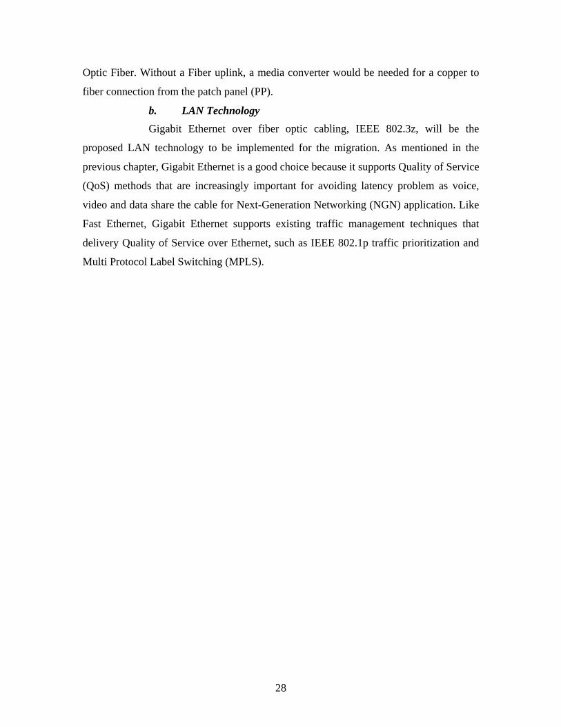
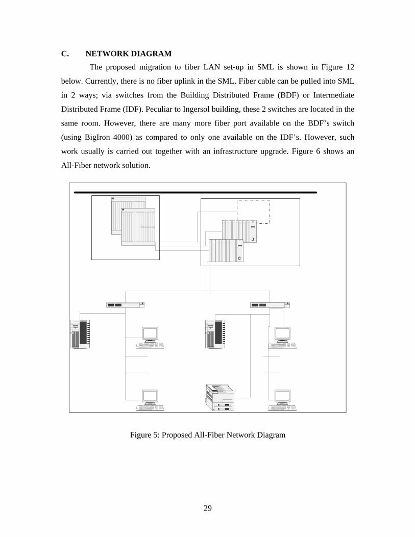
C. NETWORK DIAGRAM The proposed migration to fiber LAN set-up in SML is shown in Figure 12
below. Currently, there is no fiber uplink in the SML. Fiber cable can be pulled into SML
in 2 ways; via switches from the Building Distributed Frame (BDF) or Intermediate
Distributed Frame (IDF). Peculiar to Ingersol building, these 2 switches are located in the
same room. However, there are many more fiber port available on the BDF’s switch
(using BigIron 4000) as compared to only one available on the IDF’s. However, such
work usually is carried out together with an infrastructure upgrade. Figure 6 shows an
All-Fiber network solution.
latigid
Com3
latigid
Com3
IDC IDC
Figure 5: Proposed All-Fiber Network Diagram
30
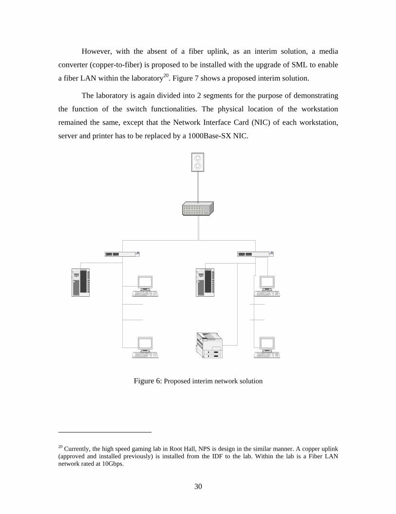
However, with the absent of a fiber uplink, as an interim solution, a media
converter (copper-to-fiber) is proposed to be installed with the upgrade of SML to enable
a fiber LAN within the laboratory20. Figure 7 shows a proposed interim solution.
The laboratory is again divided into 2 segments for the purpose of demonstrating
the function of the switch functionalities. The physical location of the workstation
remained the same, except that the Network Interface Card (NIC) of each workstation,
server and printer has to be replaced by a 1000Base-SX NIC.
Com3 Com3
IDC IDC
Figure 6: Proposed interim network solution
20 Currently, the high speed gaming lab in Root Hall, NPS is design in the similar manner. A copper uplink (approved and installed previously) is installed from the IDF to the lab. Within the lab is a Fiber LAN network rated at 10Gbps.
31
D. LIST OF HARDWARE/SOFTWARE AND COST
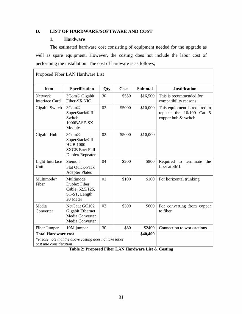
1. Hardware The estimated hardware cost consisting of equipment needed for the upgrade as
well as spare equipment. However, the costing does not include the labor cost of
performing the installation. The cost of hardware is as follows;
Proposed Fiber LAN Hardware List
Item Specification Qty Cost Subtotal Justification
Network Interface Card
3Com® Gigabit Fiber-SX NIC
30 $550 $16,500 This is recommended for compatibility reasons
Gigabit Switch 3Com® SuperStack® II Switch 1000BASE-SX Module
02 $5000 $10,000
Gigabit Hub 3Com® SuperStack® II HUB 1000 SXGB Enet Full Duplex Repeater
02 $5000 $10,000
This equipment is required to replace the 10/100 Cat 5 copper hub & switch
Light Interface Unit
Siemon Flat Quick-Pack Adapter Plates
04 $200 $800 Required to terminate the fiber at SML
Multimode* Fiber
Multimode Duplex Fiber Cable, 62.5/125, ST-ST, Length 20 Meter
01 $100 $100 For horizontal trunking
Media Converter
NetGear GC102 Gigabit Ethernet Media Converter Media Converter
02 $300 $600 For converting from copper to fiber
Fiber Jumper 10M jumper 30 $80 $2400 Connection to workstations Total Hardware cost *Please note that the above costing does not take labor cost into consideration
$40,400
Table 2: Proposed Fiber LAN Hardware List & Costing
32
2. Software As this proposed upgrade to fiber consists mostly of hardware components
upgrade, there is negligible new software requirement. The drivers for the various
proposed hardware may be bundled together with the hardware purchase. However, at
this point of the proposal, no software costs are available.
E. IMPLEMENTATION CONSIDERATION AND CHALLENGES
1. Compatibility Issue As in any network upgrade, there will be compatibility issues with hardware and
in particular, software. The foreseeable compatibility with hardware could be minimized
through careful selection of equipment to be purchased. However, the compatibility with
software could be a much more challenging issue. It is not a simple straight forward
upgrade as software and drivers may not work well with Windows 2000NT or Window
XP.
2. Infrastructure Constraint The SML lab network infrastructure is not ready for a Fiber upgrade. As it is
today, laboratory does not have a Fiber uplink form the Building Distribution Frame
(BDF). With the absent of a Fiber uplink, the upgrade will not be able achieve an All-
Fiber LAN network. Until funding is approved, the Gigabit Ethernet is achievable with
the SML.
33
IV. CONCLUSION AND RECOMMENDATION
A. CONCLUSION Fiber optic cabling has long held an advantage over copper in bandwidth, distance
and reliability. Moreover, today’s lower fiber component costs and new media converters
enable customers to migrate gradually from copper to fiber. These lower costs are partly
attributable to simplified connector design and high-density, small form-factor connectors.
These new technological advances abolish the long-standing tenet that deploying fiber in
the horizontal necessitated a major upgrade.
Traditional assumptions about the costs of fiber optic cabling must now yield to
new network designs that, by leveraging fiber’s longer distances, enable the reduction
and elimination of costly telecomm rooms and, in so doing, effect costs savings. To the
list of fiber’s well-known benefits of exceptionally high bandwidth and immunity to
electrical interference, we can now add the benefit of significant cost reductions.
In summary, the migration to Fiber in SML is recommended given the cost
effectiveness of having such a network as well as meeting NPS future demands for higher
bandwidth. The lesson to be learned from the migration of SML to fiber would be
valuable in NPS future infrastructure upgrading in the foreseeable future.
B. FUTURE WORK With rapid growth of Internet technologies and applications into the 2000s,
demand for faster PCs continues to grow as it has in the past. As applications grew more
bandwidth hungry, the view that 100Mbps was adequate at the desktop began to change
and the trend to 1Gbs desktops develops. This trend greatly accelerated when the cost of
Gigabit Ethernet approaching the cost of regular Ethernet.
As a rule of thumb, the backbone capacity should be 10 times that of the LAN
capacity. Currently, NPS Fiber backbone is only rated at 1Gbps. With the demand for
more bandwidth, will our network infrastructure and backbone be large enough to
support increasing workgroup or segment? Such foreseeable problems require immediate
attention as the upgrading of network infrastructure requires extensive research and

34
construction time. These areas are thus strongly recommended for thesis work in NPS
network infrastructure.
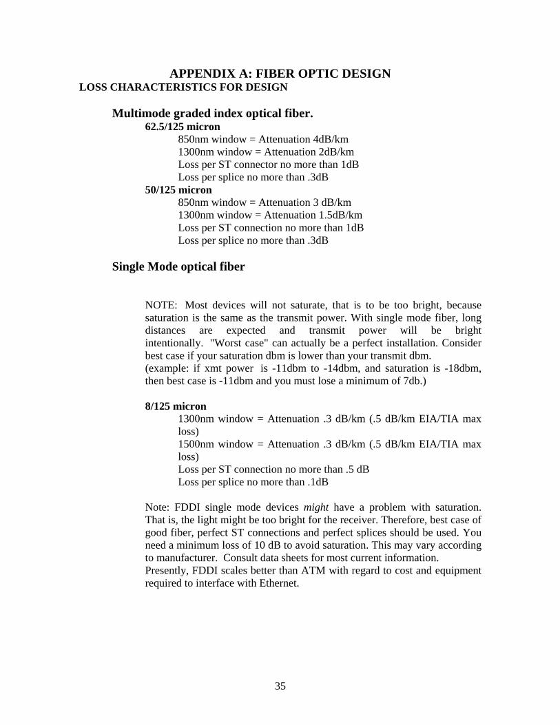
35
APPENDIX A: FIBER OPTIC DESIGN LOSS CHARACTERISTICS FOR DESIGN
Multimode graded index optical fiber. 62.5/125 micron 850nm window = Attenuation 4dB/km 1300nm window = Attenuation 2dB/km Loss per ST connector no more than 1dB Loss per splice no more than .3dB 50/125 micron
850nm window = Attenuation 3 dB/km 1300nm window = Attenuation 1.5dB/km Loss per ST connection no more than 1dB Loss per splice no more than .3dB
Single Mode optical fiber
NOTE: Most devices will not saturate, that is to be too bright, because saturation is the same as the transmit power. With single mode fiber, long distances are expected and transmit power will be bright intentionally. "Worst case" can actually be a perfect installation. Consider best case if your saturation dbm is lower than your transmit dbm. (example: if xmt power is -11dbm to -14dbm, and saturation is -18dbm, then best case is -11dbm and you must lose a minimum of 7db.) 8/125 micron
1300nm window = Attenuation .3 dB/km (.5 dB/km EIA/TIA max loss) 1500nm window = Attenuation .3 dB/km (.5 dB/km EIA/TIA max loss) Loss per ST connection no more than .5 dB Loss per splice no more than .1dB
Note: FDDI single mode devices might have a problem with saturation. That is, the light might be too bright for the receiver. Therefore, best case of good fiber, perfect ST connections and perfect splices should be used. You need a minimum loss of 10 dB to avoid saturation. This may vary according to manufacturer. Consult data sheets for most current information. Presently, FDDI scales better than ATM with regard to cost and equipment required to interface with Ethernet.
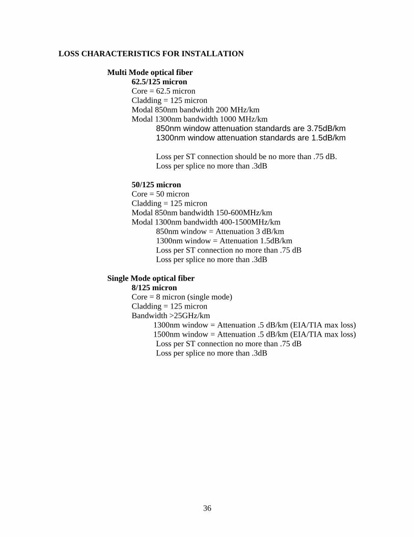
36
LOSS CHARACTERISTICS FOR INSTALLATION Multi Mode optical fiber 62.5/125 micron Core = 62.5 micron Cladding = 125 micron Modal 850nm bandwidth 200 MHz/km Modal 1300nm bandwidth 1000 MHz/km
850nm window attenuation standards are 3.75dB/km 1300nm window attenuation standards are 1.5dB/km
Loss per ST connection should be no more than .75 dB. Loss per splice no more than .3dB 50/125 micron Core = 50 micron Cladding = 125 micron Modal 850nm bandwidth 150-600MHz/km Modal 1300nm bandwidth 400-1500MHz/km 850nm window = Attenuation 3 dB/km 1300nm window = Attenuation 1.5dB/km Loss per ST connection no more than .75 dB Loss per splice no more than .3dB
Single Mode optical fiber 8/125 micron Core = 8 micron (single mode) Cladding = 125 micron Bandwidth >25GHz/km 1300nm window = Attenuation .5 dB/km (EIA/TIA max loss) 1500nm window = Attenuation .5 dB/km (EIA/TIA max loss) Loss per ST connection no more than .75 dB Loss per splice no more than .3dB
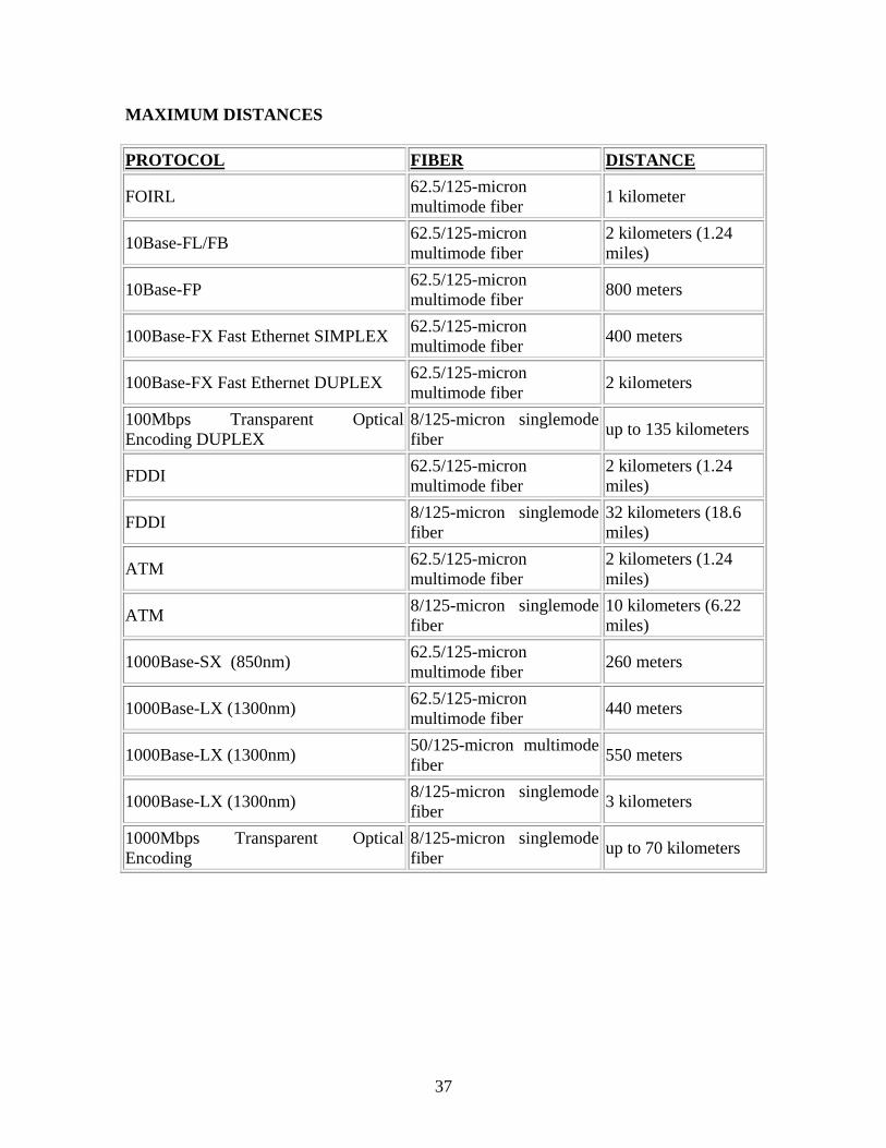
37
MAXIMUM DISTANCES PROTOCOL FIBER DISTANCE
FOIRL 62.5/125-micron multimode fiber 1 kilometer
10Base-FL/FB 62.5/125-micron multimode fiber
2 kilometers (1.24 miles)
10Base-FP 62.5/125-micron multimode fiber 800 meters
100Base-FX Fast Ethernet SIMPLEX 62.5/125-micron multimode fiber 400 meters
100Base-FX Fast Ethernet DUPLEX 62.5/125-micron multimode fiber 2 kilometers
100Mbps Transparent Optical Encoding DUPLEX
8/125-micron singlemode fiber up to 135 kilometers
FDDI 62.5/125-micron multimode fiber
2 kilometers (1.24 miles)
FDDI 8/125-micron singlemode fiber
32 kilometers (18.6 miles)
ATM 62.5/125-micron multimode fiber
2 kilometers (1.24 miles)
ATM 8/125-micron singlemode fiber
10 kilometers (6.22 miles)
1000Base-SX (850nm) 62.5/125-micron multimode fiber 260 meters
1000Base-LX (1300nm) 62.5/125-micron multimode fiber 440 meters
1000Base-LX (1300nm) 50/125-micron multimode fiber 550 meters
1000Base-LX (1300nm) 8/125-micron singlemode fiber 3 kilometers
1000Mbps Transparent Optical Encoding
8/125-micron singlemode fiber up to 70 kilometers
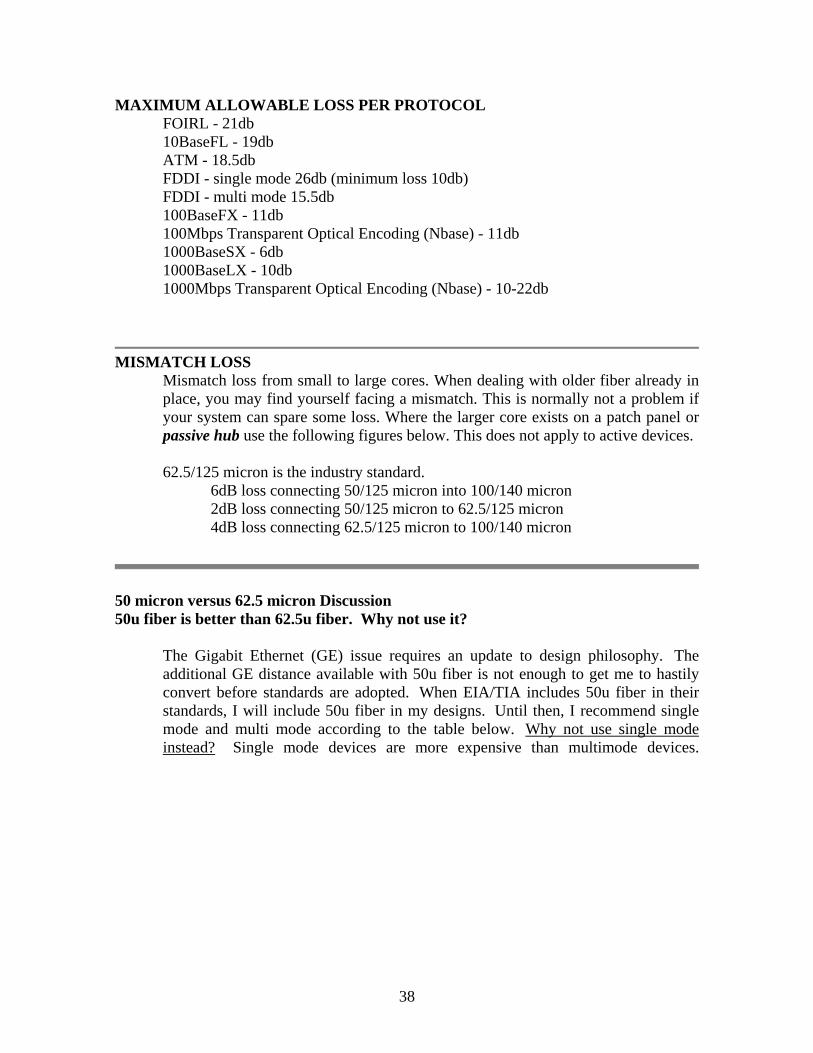
38
MAXIMUM ALLOWABLE LOSS PER PROTOCOL FOIRL - 21db 10BaseFL - 19db ATM - 18.5db FDDI - single mode 26db (minimum loss 10db) FDDI - multi mode 15.5db 100BaseFX - 11db 100Mbps Transparent Optical Encoding (Nbase) - 11db 1000BaseSX - 6db 1000BaseLX - 10db 1000Mbps Transparent Optical Encoding (Nbase) - 10-22db
MISMATCH LOSS
Mismatch loss from small to large cores. When dealing with older fiber already in place, you may find yourself facing a mismatch. This is normally not a problem if your system can spare some loss. Where the larger core exists on a patch panel or passive hub use the following figures below. This does not apply to active devices. 62.5/125 micron is the industry standard.
6dB loss connecting 50/125 micron into 100/140 micron 2dB loss connecting 50/125 micron to 62.5/125 micron 4dB loss connecting 62.5/125 micron to 100/140 micron
50 micron versus 62.5 micron Discussion 50u fiber is better than 62.5u fiber. Why not use it?
The Gigabit Ethernet (GE) issue requires an update to design philosophy. The additional GE distance available with 50u fiber is not enough to get me to hastily convert before standards are adopted. When EIA/TIA includes 50u fiber in their standards, I will include 50u fiber in my designs. Until then, I recommend single mode and multi mode according to the table below. Why not use single mode instead? Single mode devices are more expensive than multimode devices.
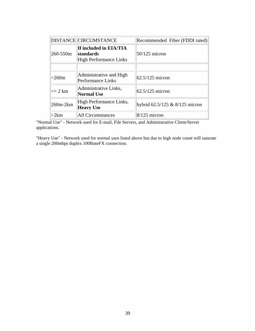
39
DISTANCE CIRCUMSTANCE Recommended Fiber (FDDI rated)
260-550m If included in EIA/TIA standards High Performance Links
50/125 micron
<260m Administrative and High Performance Links 62.5/125 micron
<= 2 km Administrative Links, Normal Use 62.5/125 micron
260m-2km High Performance Links, Heavy Use hybrid 62.5/125 & 8/125 micron
>2km All Circumstances 8/125 micron "Normal Use" - Network used for E-mail, File Servers, and Administrative Client/Server applications. "Heavy Use" - Network used for normal uses listed above but due to high node count will saturate a single 200mbps duplex 100BaseFX connection.

40
THIS PAGE INTENTIONALLY LEFT BLANK
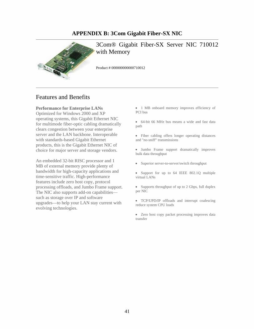
41
APPENDIX B: 3Com Gigabit Fiber-SX NIC
3Com® Gigabit Fiber-SX Server NIC 710012with Memory
Product # 000000000000710012
Features and Benefits
Performance for Enterprise LANs Optimized for Windows 2000 and XP operating systems, this Gigabit Ethernet NIC for multimode fiber-optic cabling dramatically clears congestion between your enterprise server and the LAN backbone. Interoperable with standards-based Gigabit Ethernet products, this is the Gigabit Ethernet NIC of choice for major server and storage vendors. An embedded 32-bit RISC processor and 1 MB of external memory provide plenty of bandwidth for high-capacity applications and time-sensitive traffic. High-performance features include zero host copy, protocol processing offloads, and Jumbo Frame support. The NIC also supports add-on capabilities—such as storage over IP and software upgrades—to help your LAN stay current with evolving technologies.
• 1 MB onboard memory improves efficiency of PCI bus
• 64-bit 66 MHz bus means a wide and fast data path
• Fiber cabling offers longer operating distances and "no-sniff" transmissions
• Jumbo Frame support dramatically improves bulk data throughput
• Superior server-to-server/switch throughput
• Support for up to 64 IEEE 802.1Q multiple virtual LANs
• Supports throughput of up to 2 Gbps, full duplex per NIC
• TCP/UPD/IP offloads and interrupt coalescing reduce system CPU loads
• Zero host copy packet processing improves data transfer

42
THIS PAGE INTENTIONALLY LEFT BLANK
43
APPENDIX C: 3Com® SuperStack® II Switch 1000BASE-SX Module 3Com® SuperStack® II Switch 1000BASE-SX Module Product #: 3C16975
Features, Benefits & Specifications
Gigabit Ethernet Backbone Performance Plus Resilience
Scale the performance of your Ethernet/Fast Ethernet network to gigabit speeds by adding
this module to 3COM® SuperStack II Switch 1100s and SuperStack 3 Switch 3300s. This
module provides a high-performance interworkgroup or workgroup-to-backbone Gigabit
Ethernet connection. Dual links ensure resilience.
• Provides full-duplex multimode fiber interface at distances up to 550 m (1,804 ft)
• Support for 802.3z full-duplex Gigabit Ethernet delivers up to 2 Gbps throughput
• Provides a resilient link backbone to improve overall fault tolerance
• Slides easily into the expansion slot behind the switch
• Standards-based 802.1p, 802.1Q, and multicast filtering support multimedia
applications

44
THIS PAGE INTENTIONALLY LEFT BLANK
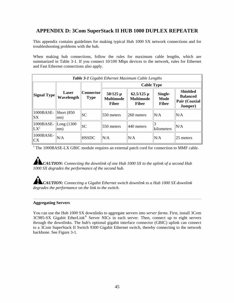
45
APPENDIX D: 3Com SuperStack II HUB 1000 DUPLEX REPEATER
This appendix contains guidelines for making typical Hub 1000 SX network connections and for troubleshooting problems with the hub.
When making hub connections, follow the rules for maximum cable lengths, which are summarized in Table 3-1. If you connect 10/100 Mbps devices to the network, rules for Ethernet and Fast Ethernet connections also apply.
Table 3-1 Gigabit Ethernet Maximum Cable Lengths Cable Type
Signal Type Laser Wavelength
Connector Type
50/125 µ Multimode
Fiber
62.5/125 µ Multimode
Fiber
Single-Mode Fiber
Shielded Balanced
Pair (Coaxial Jumper)
1000BASE-SX
Short (850 nm) SC 550 meters 260 meters N/A N/A
1000BASE-LX1
Long (1300 nm) SC 550 meters 440 meters 3
kilometers N/A
1000BASE-CX N/A HSSDC N/A N/A N/A 25 meters
1 The 1000BASE-LX GBIC module requires an external patch cord for connection to MMF cable.
CAUTION: Connecting the downlink of one Hub 1000 SX to the uplink of a second Hub 1000 SX degrades the performance of the second hub.
CAUTION: Connecting a Gigabit Ethernet switch downlink to a Hub 1000 SX downlink degrades the performance on the link to the switch.
Aggregating Servers
You can use the Hub 1000 SX downlinks to aggregate servers into server farms. First, install 3Com 3C985-SX Gigabit EtherLink® Server NICs in each server. Then, connect up to eight servers through the downlinks. The hub's optional gigabit interface connector (GBIC) uplink can connect to a 3Com SuperStack II Switch 9300 Gigabit Ethernet switch, thereby connecting to the network backbone. See Figure 3-1.
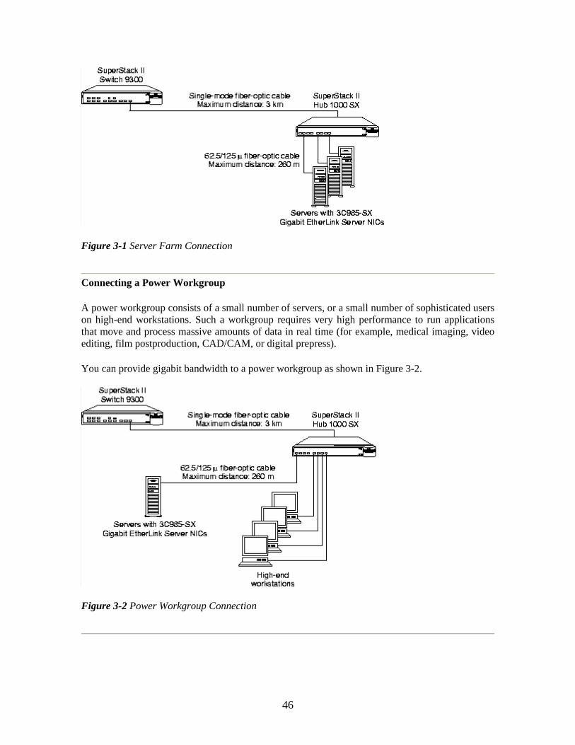
46
Figure 3-1 Server Farm Connection
Connecting a Power Workgroup
A power workgroup consists of a small number of servers, or a small number of sophisticated users on high-end workstations. Such a workgroup requires very high performance to run applications that move and process massive amounts of data in real time (for example, medical imaging, video editing, film postproduction, CAD/CAM, or digital prepress).
You can provide gigabit bandwidth to a power workgroup as shown in Figure 3-2.
Figure 3-2 Power Workgroup Connection
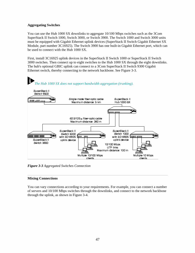
47
Aggregating Switches
You can use the Hub 1000 SX downlinks to aggregate 10/100 Mbps switches such as the 3Com SuperStack II Switch 1000, Switch 3000, or Switch 3900. The Switch 1000 and Switch 3000 units must be equipped with Gigabit Ethernet uplink devices (SuperStack II Switch Gigabit Ethernet SX Module, part number 3C16925). The Switch 3900 has one built-in Gigabit Ethernet port, which can be used to connect with the Hub 1000 SX.
First, install 3C16925 uplink devices in the SuperStack II Switch 1000 or SuperStack II Switch 3000 switches. Then connect up to eight switches to the Hub 1000 SX through the eight downlinks. The hub's optional GBIC uplink can connect to a 3Com SuperStack II Switch 9300 Gigabit Ethernet switch, thereby connecting to the network backbone. See Figure 3-3.
The Hub 1000 SX does not support bandwidth aggregation (trunking).
Figure 3-3 Aggregated Switches Connection
Mixing Connections
You can vary connections according to your requirements. For example, you can connect a number of servers and 10/100 Mbps switches through the downlinks, and connect to the network backbone through the uplink, as shown in Figure 3-4.
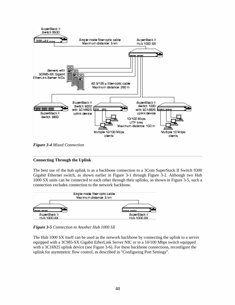
48
Figure 3-4 Mixed Connection
Connecting Through the Uplink
The best use of the hub uplink is as a backbone connection to a 3Com SuperStack II Switch 9300 Gigabit Ethernet switch, as shown earlier in Figure 3-1 through Figure 3-2. Although two Hub 1000 SX units can be connected to each other through their uplinks, as shown in Figure 3-5, such a connection excludes connection to the network backbone.
Figure 3-5 Connection to Another Hub 1000 SX
The Hub 1000 SX itself can be used as the network backbone by connecting the uplink to a server equipped with a 3C985-SX Gigabit EtherLink Server NIC or to a 10/100 Mbps switch equipped with a 3C16925 uplink device (see Figure 3-6). For these backbone connections, reconfigure the uplink for asymmetric flow control, as described in "Configuring Port Settings”.
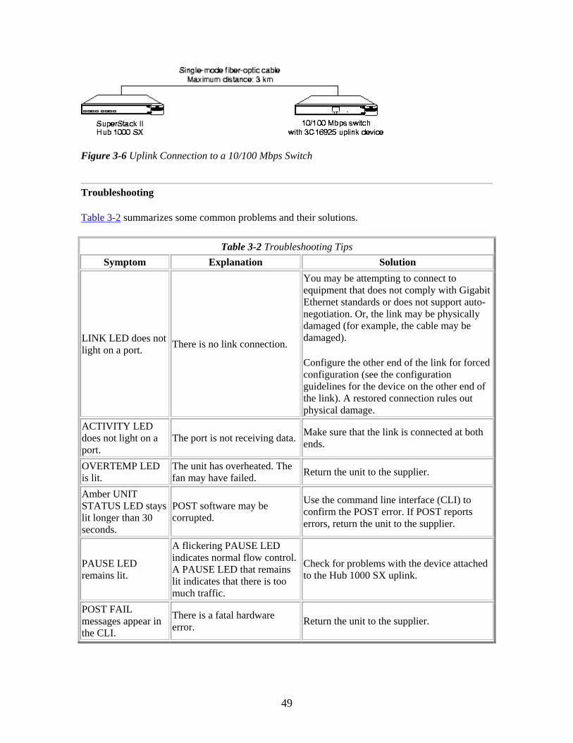
49
Figure 3-6 Uplink Connection to a 10/100 Mbps Switch
Troubleshooting
Table 3-2 summarizes some common problems and their solutions.
Table 3-2 Troubleshooting Tips Symptom Explanation Solution
LINK LED does not light on a port. There is no link connection.
You may be attempting to connect to equipment that does not comply with Gigabit Ethernet standards or does not support auto-negotiation. Or, the link may be physically damaged (for example, the cable may be damaged).
Configure the other end of the link for forced configuration (see the configuration guidelines for the device on the other end of the link). A restored connection rules out physical damage.
ACTIVITY LED does not light on a port.
The port is not receiving data. Make sure that the link is connected at both ends.
OVERTEMP LED is lit.
The unit has overheated. The fan may have failed. Return the unit to the supplier.
Amber UNIT STATUS LED stays lit longer than 30 seconds.
POST software may be corrupted.
Use the command line interface (CLI) to confirm the POST error. If POST reports errors, return the unit to the supplier.
PAUSE LED remains lit.
A flickering PAUSE LED indicates normal flow control. A PAUSE LED that remains lit indicates that there is too much traffic.
Check for problems with the device attached to the Hub 1000 SX uplink.
POST FAIL messages appear in the CLI.
There is a fatal hardware error. Return the unit to the supplier.

50
THIS PAGE INTENTIONALLY LEFT BLANK
51
LIST OF REFERENCES
[1] The Fiber Optic LAN Handbook (Fifth Edition) published in 1993 Prepared by The Marketing Department of Codenoll Technology Corporation – Codenoll Technology Corporation
[2] Gigabit Ethernet Networking - David G. Cunningham, Ph.D. & William G. Lane, Ph.D.
[3] Evolution of Gigabit Technology - White paper by Intel
[4] Gigabit Ethernet Networking Solutions - Whitepaper by Cisco & Intel
[5] Horizontal Cabling Costs: Fiber vs. UTP - Fiber Optics LAN Section (FOLS) of Telecommunication Industry Association
[6] Fiber in the Horizontal: The Better Way to Carry Information - Fiber Optics LAN Section (FOLS) of Telecommunication Industry Association
[7] Optical Fiber Local Area Network: Bandwidth, Data Rate, and Link Length – What Does It All Mean? - Doug Harshbarger, 1997 Whitepaper by Corning
[8] Fiber Optic Design - Anthony P.McCullough (1997)
[9] Fiber to Desk: What it is cost effective today - John Struhar, Chair, TIA Fiber Optics LAN Section

52
THIS PAGE INTENTIONALLY LEFT BLANK
53
INITIAL DISTRIBUTION LIST
1. Defense Technical Information Center
Ft. Belvoir, Virginia
2. Dudley Knox Library Monterey, California
3. Chair, IS Department
Naval Postgraduate School Monterey, California
4. Professor Norman Schneidewind
Naval Postgraduate School Monterey, California
5. Professor Douglas Brinkley
Naval Postgraduate School Monterey, California
6. Major Ee Chai Chuan
Ministry of Defense, Singapore
![6. Wiring Diagram - weidefamily.net coil Transmission control module ... WIRING DIAGRAM 6. Wiring Diagram. MEMO: 21 WIRING DIAGRAM ... 76 6-3 [D6R2] WIRING DIAGRAM 6](https://img.pdfslide.us/doc/110x75/5aa0cc3b7f8b9a62178ea5e7/6-wiring-diagram-coil-transmission-control-module-wiring-diagram-6-wiring.jpg)


![5. Wiring Diagram - Subaru Forester. Wiring Diagram A: POWER SUPPLY ROUTING SU01-04A 12 6-3 [D5A0] WIRING DIAGRAM 5. Wiring Diagram SU01-04B 13 WIRING DIAGRAM [D5A0] 6-3 5. Wiring](https://img.pdfslide.us/doc/110x75/5aa205fe7f8b9a1f6d8cac3f/5-wiring-diagram-subaru-wiring-diagram-a-power-supply-routing-su01-04a-12.jpg)