Embed Size (px)
Citation preview
NAVALPOSTGRADUATE
SCHOOL
MONTEREY, CALIFORNIA
THESIS
MESH NETWORKING IN THE TACTICALENVIRONMENT USING WHITE SPACE TECHNOLOGY
by
Simon Sanchez
December 2015
Thesis Advisor: Geoffrey XieSecond Reader: John Gibson
Approved for public release; distribution is unlimited

THIS PAGE INTENTIONALLY LEFT BLANK
REPORT DOCUMENTATION PAGE Form Approved OMB No. 0704–0188
Public reporting burden for this collection of information is estimated to average 1 hour per response, including the time for reviewing instruction,searching existing data sources, gathering and maintaining the data needed, and completing and reviewing the collection of information. Send commentsregarding this burden estimate or any other aspect of this collection of information, including suggestions for reducing this burden to Washingtonheadquarters Services, Directorate for Information Operations and Reports, 1215 Jefferson Davis Highway, Suite 1204, Arlington, VA 22202–4302, andto the Office of Management and Budget, Paperwork Reduction Project (0704-0188) Washington DC 20503.
1. AGENCY USE ONLY (Leave Blank) 2. REPORT DATE
12-18-20153. REPORT TYPE AND DATES COVERED
Master’s Thesis 01-04-2014 to 12-18-20154. TITLE AND SUBTITLE
MESH NETWORKING IN THE TACTICAL ENVIRONMENT USING WHITE SPACETECHNOLOGY
5. FUNDING NUMBERS
6. AUTHOR(S)
Simon Sanchez
7. PERFORMING ORGANIZATION NAME(S) AND ADDRESS(ES)
Naval Postgraduate SchoolMonterey, CA 93943
8. PERFORMING ORGANIZATION REPORTNUMBER
9. SPONSORING / MONITORING AGENCY NAME(S) AND ADDRESS(ES)
N/A
10. SPONSORING / MONITORINGAGENCY REPORT NUMBER
11. SUPPLEMENTARY NOTES
The views expressed in this document are those of the author and do not reflect the official policy or position of the Department ofDefense or the U.S. Government. IRB Protocol Number: N/A.
12a. DISTRIBUTION / AVAILABILITY STATEMENT
Approved for public release; distribution is unlimited12b. DISTRIBUTION CODE
13. ABSTRACT (maximum 200 words)
The transition of the military from wars within two known and established theaters to a focus on a dynamic and hastily occupied combat environment necessitates the need for a similarly dynamic and adaptable communications backbone. Traditionally, Army units have relied on either FM communications over short distances or expensive radios to communicate over long distances. FM communications often require retransmission to extend their reach while expensive radio systems often rely on other resources such as satellites. The analog-to-digital television conversion saw the birth of white space spectral technology, which dynamically allocates unutilized spectral space within the television broadcast range to transmit data. This research explores the use of white space spectral technology in the creation of a dynamically established communications infrastructure for the purpose of repeating communications originating from numerous existing platforms in the tactical environment. A comparative analysis was conducted between an imple-mentation of this technology, the Carlson Rural Connect, and similar solutions, specifically, a variant of the Harris 117G, currently available within the military in order to explore the merit of this technology for use as a communications relay in the tactical environ-ment. The results obtained in these experiments demonstrate the potential use of white space technology as a repeater in the tactical environment. Though this potential exists, this technology requires time, a dedicated development effort, and additional testing and experimentation before it is refined enough for use in military operations.
14. SUBJECT TERMS
tactical communications, white space, relay, television15. NUMBER OF
PAGES 8316. PRICE CODE
17. SECURITYCLASSIFICATION OFREPORT
Unclassified
18. SECURITYCLASSIFICATION OF THISPAGE
Unclassified
19. SECURITYCLASSIFICATION OFABSTRACT
Unclassified
20. LIMITATION OFABSTRACT
UUNSN 7540-01-280-5500 Standard Form 298 (Rev. 2–89)
Prescribed by ANSI Std. 239–18
i

THIS PAGE INTENTIONALLY LEFT BLANK
ii
Approved for public release; distribution is unlimited
MESH NETWORKING IN THE TACTICAL ENVIRONMENT USING WHITESPACE TECHNOLOGY
Simon SanchezCaptain, United States Army
B.A., University of Texas at Austin, 2004
Submitted in partial fulfillment of therequirements for the degree of
MASTER OF SCIENCE IN COMPUTER SCIENCE
from the
NAVAL POSTGRADUATE SCHOOLDecember 2015
Author: Simon Sanchez
Approved by: Geoffrey XieThesis Advisor
John GibsonSecond Reader
Peter J. DenningChair, Department of Computer Science
iii

THIS PAGE INTENTIONALLY LEFT BLANK
iv
ABSTRACT
The transition of the military from wars within two known and established theaters to afocus on a dynamic and hastily occupied combat environment necessitates the need fora similarly dynamic and adaptable communications backbone. Traditionally, Army unitshave relied on either FM communications over short distances or expensive radios to com-municate over long distances. FM communications often require retransmission to extendtheir reach while expensive radio systems often rely on other resources such as satellites.The analog-to-digital television conversion saw the birth of white space spectral technol-ogy, which dynamically allocates unutilized spectral space within the television broadcastrange to transmit data. This research explores the use of white space spectral technologyin the creation of a dynamically established communications infrastructure for the purposeof repeating communications originating from numerous existing platforms in the tacticalenvironment. A comparative analysis was conducted between an implementation of thistechnology, the Carlson Rural Connect, and similar solutions, specifically, a variant of theHarris 117G, currently available within the military in order to explore the merit of thistechnology for use as a communications relay in the tactical environment. The results ob-tained in these experiments demonstrate the potential use of white space technology as arepeater in the tactical environment. Though this potential exists, this technology requirestime, a dedicated development effort, and additional testing and experimentation before itis refined enough for use in military operations.
v

THIS PAGE INTENTIONALLY LEFT BLANK
vi
Table of Contents
1 Introduction 11.1 Problem Statement. . . . . . . . . . . . . . . . . . . . . . . . 1
1.2 Research Description. . . . . . . . . . . . . . . . . . . . . . . 2
1.3 Research Benefits . . . . . . . . . . . . . . . . . . . . . . . . 3
1.4 Organization . . . . . . . . . . . . . . . . . . . . . . . . . . 3
2 Background 52.1 Current Relay Practices . . . . . . . . . . . . . . . . . . . . . . 5
2.2 Modern DOD Utilized Solutions . . . . . . . . . . . . . . . . . . 8
2.3 White Space Spectral Technology Relay Solution . . . . . . . . . . . 11
3 Methodology 193.1 Experimentation Goals . . . . . . . . . . . . . . . . . . . . . . 19
3.2 Lines of Experimentation . . . . . . . . . . . . . . . . . . . . . 21
3.3 Equipment Configuration . . . . . . . . . . . . . . . . . . . . . 25
3.4 Multi-hop simulation . . . . . . . . . . . . . . . . . . . . . . . 29
4 Findings 354.1 Employment Potential . . . . . . . . . . . . . . . . . . . . . . 36
4.2 Comparison to Current Military Specification Meeting Equipment . . . . . 42
4.3 Tactical Performance . . . . . . . . . . . . . . . . . . . . . . . 44
4.4 Multi-Hop Testing . . . . . . . . . . . . . . . . . . . . . . . . 46
5 Conclusions 535.1 Usability . . . . . . . . . . . . . . . . . . . . . . . . . . . 53
5.2 Performance . . . . . . . . . . . . . . . . . . . . . . . . . . 55
5.3 Maturity of Technology . . . . . . . . . . . . . . . . . . . . . . 57
5.4 Conclusions . . . . . . . . . . . . . . . . . . . . . . . . . . 58
5.5 Recommendations for Future Work . . . . . . . . . . . . . . . . . 59
vii

List of References 61
Initial Distribution List 65
viii
List of Figures
Figure 2.1 Carlson Wireless modulation use table, from [19] . . . . . . . . 16
Figure 2.2 Carlson Wireless omni-directional antenna, utilized with base sta-tion node . . . . . . . . . . . . . . . . . . . . . . . . . . . . . . 16
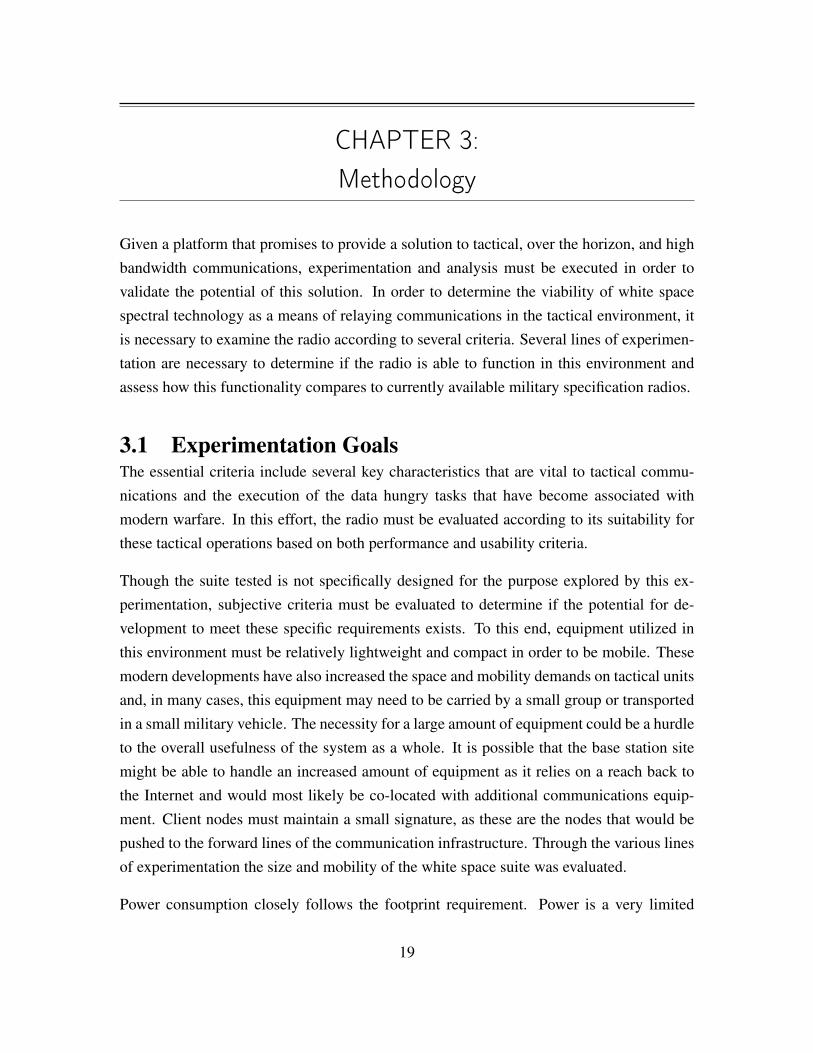
Figure 2.3 Carlson Wireless yagi antenna, utilized at client nodes . . . . . . 17
Figure 3.1 Map of JIFX training area utilized for testing . . . . . . . . . . . 21
Figure 3.2 Conceptual sketch of simulated multi-hop network . . . . . . . . 24
Figure 3.3 Rural Connect TV base station enclosure . . . . . . . . . . . . . 26
Figure 3.4 JIFX 15-04 testing configuration . . . . . . . . . . . . . . . . . 27
Figure 3.5 JIFX 15-04 testing configuration . . . . . . . . . . . . . . . . . 27
Figure 3.6 Base station testing site - in the vicinity of OP 7 . . . . . . . . . 28
Figure 3.7 Radio status and scanning settings . . . . . . . . . . . . . . . . . 29
Figure 3.8 Modulation selection . . . . . . . . . . . . . . . . . . . . . . . . 29
Figure 3.9 Simulated network architecture . . . . . . . . . . . . . . . . . . 31
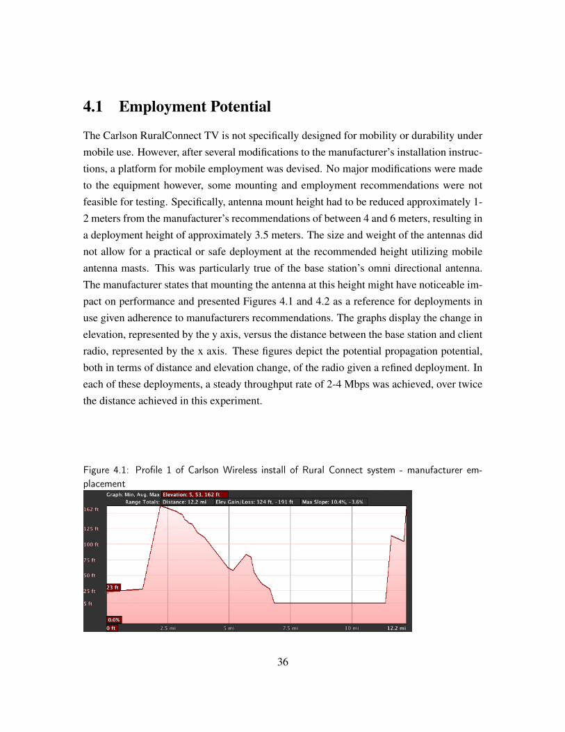
Figure 4.1 Profile 1 of Carlson Wireless install of Rural Connect system - man-ufacturer emplacement . . . . . . . . . . . . . . . . . . . . . . . 36
Figure 4.2 Profile 2 of Carlson Wireless install of Rural Connect system - man-ufacturer emplacement . . . . . . . . . . . . . . . . . . . . . . . 37
Figure 4.3 Spectrum analyzer depicting Carlson Rural Connect operating at491 Mhz . . . . . . . . . . . . . . . . . . . . . . . . . . . . . . 40
Figure 4.4 Encapsulation of data across Rural Connect network . . . . . . . 41
Figure 4.5 Graph of Harris 7800MP vs Rural Connect performance . . . . . 43
Figure 4.6 Graph of Carlson Rural Connect performance versus varying dis-tance . . . . . . . . . . . . . . . . . . . . . . . . . . . . . . . . 45
ix

Figure 4.7 Depiction of bandwidth division issues: Carlson Rural Connect . 47
Figure 4.8 Graph of simulation results: TCP transmission of 2000 kb at varyingnode distances . . . . . . . . . . . . . . . . . . . . . . . . . . . 51
x
List of Tables
Table 2.1 Comparison of capabilities between white space and competing tech-nologies . . . . . . . . . . . . . . . . . . . . . . . . . . . . . . . 15
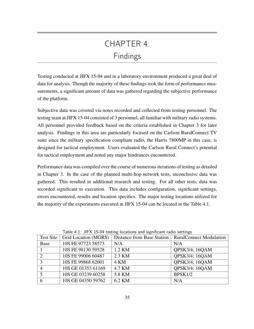
Table 4.1 JIFX 15-04 testing locations and significant radio settings . . . . . 35
Table 4.2 Results of Harris 7800MP and Rural Connect performance compari-son . . . . . . . . . . . . . . . . . . . . . . . . . . . . . . . . . . 42
Table 4.3 Results of Carlson Rural Connect throughput versus varying distance 44
Table 4.4 Results of throughput analysis of Rural Connect network with multi-ple clients . . . . . . . . . . . . . . . . . . . . . . . . . . . . . . 48
Table 4.5 Results of White Space simulation transmitting 2000 kb at varyingnode distances . . . . . . . . . . . . . . . . . . . . . . . . . . . . 50
xi

THIS PAGE INTENTIONALLY LEFT BLANK
xii
List of Acronyms and Abbreviations
ANW2 Adaptive Networking Wideband Waveform
ARP Address Resolution Protocol
C2 Command and Control
COMSEC Communications Security Encryption Keys
dBi decibel isotropic
DHCP Dynamic Host Configuration Protocol
DOD Department of Defense
FCC Federal Communications Commission
GHz gigahertz
HF high frequency
ICMP Internet Control Message Protocol
JIFX Joint Interagency Field Experimentation
JVAB Joint Vulnerability Assessment Branch
Kbp/s Kilobytes per second
kHz kilohertz
MHz megahertz
NPS Naval Postgraduate School
NSA National Security Agency
NTIA National Telecommunications Information Administration
SATCOM Satellite Communications
xiii
SINCGARS Single Channel Ground and Airborne Radio System
Transmission Control ProtocolTCP
UDP
UHF
USG
VHF
User Datagram Protocol
Ultra High Frequency
United States Government
very high frequency
xiv
Acknowledgments
I owe my wife, Natalie, a great deal of thanks for her support and advice throughout thisprocess. Not only is she a fine mother and able to masterfully juggle a household and smallbusiness, but also she is a great sounding board for my ideas. Without her, I would neverhave been able to finish this program and thesis work.
The inquisitiveness and joy for life displayed by my son, Zackary, is an inspiration. I willforever be thankful for his role in this work and the joy and motivation that he continues tobring me.
I’d like to thank Professor Geoffrey Xie for his advice and support throughout the com-pletion of this thesis work. I appreciate the freedom I was afforded to experiment and theadvice he gave me when I was unsure of how to proceed.
I thank God that by his grace I have been afforded the opportunity to be a husband, father,cavalry-man, and able to complete this latest adventure.
xv

THIS PAGE INTENTIONALLY LEFT BLANK
xvi
CHAPTER 1:Introduction
Over the course of the nation’s last two wars, fought in a counter-insurgency environment,units operating at the tactical level have generally relied on the existence of an establishedcommunications infrastructure built up over ten years of operations. As the nation shifts to-ward a focus on full-spectrum operations in an unknown and rapidly occupied theater, unitsasked to establish a foothold in this theater will undertake the task of executing operationsof a dynamic nature in an unknown communications environment.
The systems developed to leverage the combat enablers, which give these units an advan-tage on the battlefield, had the luxury of this established communications network whenutilized during the nation’s last two wars. In the future, this luxury may not be presenthowever, tactical units must still be afforded the means to bring these enablers to bear incombat. These enablers include resource intensive processes such as streaming live feedsfrom intelligence assets, dissemination of detailed imagery, or transmission of intelligencedata.
1.1 Problem StatementThe hasty establishment of a communications infrastructure for units to distribute informa-tion on the ground is vital to the employment of enablers and new systems developed to relyon a robust communications infrastructure. The success of operations executed against thenear peer enemies American forces prepare to encounter in the future is, to some degree,dependent on these systems. Communications over the horizon and past line-of-sight arenecessary to provide capabilities to units on the frontlines of an engagement.
In this thesis, current means to provide inter-theater connectivity will be evaluated and newtechnology, namely white space technology systems, will be explored in order to attemptto find the system that is most capable of providing persistent, reliable, adaptable, and longreaching connectivity to units at the battalion size and smaller; element sizes vital in op-erations designed to gain access to terrain in an austere, fluid, and dynamic environment.Systems will be evaluated in terms of several key performance factors including: through-
1
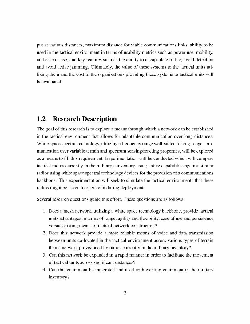
put at various distances, maximum distance for viable communications links, ability to beused in the tactical environment in terms of usability metrics such as power use, mobility,and ease of use, and key features such as the ability to encapsulate traffic, avoid detectionand avoid active jamming. Ultimately, the value of these systems to the tactical units uti-lizing them and the cost to the organizations providing these systems to tactical units willbe evaluated.
1.2 Research DescriptionThe goal of this research is to explore a means through which a network can be establishedin the tactical environment that allows for adaptable communication over long distances.White space spectral technology, utilizing a frequency range well-suited to long-range com-munication over variable terrain and spectrum sensing/reacting properties, will be exploredas a means to fill this requirement. Experimentation will be conducted which will comparetactical radios currently in the military’s inventory using native capabilities against similarradios using white space spectral technology devices for the provision of a communicationsbackbone. This experimentation will seek to simulate the tactical environments that theseradios might be asked to operate in during deployment.
Several research questions guide this effort. These questions are as follows:
1. Does a mesh network, utilizing a white space technology backbone, provide tacticalunits advantages in terms of range, agility and flexibility, ease of use and persistenceversus existing means of tactical network construction?
2. Does this network provide a more reliable means of voice and data transmissionbetween units co-located in the tactical environment across various types of terrainthan a network provisioned by radios currently in the military inventory?
3. Can this network be expanded in a rapid manner in order to facilitate the movementof tactical units across significant distances?
4. Can this equipment be integrated and used with existing equipment in the militaryinventory?
2
1.3 Research BenefitsThis study benefits the Department of Defense (DOD) and tactical military units specifi-cally, by exploring the concept of an adaptable, expandable, hastily established, and costeffective network in the tactical environment as a means of increasing the ability of tacticalforces to maneuver on the battlefield without loss on critical Command and Control (C2)links, thereby allowing the tactical commander to maintain the initiative and leverage tacti-cal advantages without increasing the risk that distributed forces may become isolated fromcritical communications infrastructures. This network provides a means to utilize existingand readily available equipment over a backbone designed to adapt to varying spectral en-vironments. This study will provide the background to ensure that tactical units have ameans to ensure intra-theater communications, which is vital to mission success.
1.4 OrganizationChapter 2 provides background information on the possible available solutions capable ofrepeating voice and data communications in the tactical environment. Solutions existingwithin the current military inventory, in the early stages of fielding, and in the civiliansector will be analyzed and evaluated. The history of white space spectral technology willalso be discussed along with its current development in the civilian sector.
Chapter 3 provides details on the experimentation model, the process by which the exper-iment was established and the metrics evaluated and measured. The specific equipmentutilized and the various configurations of tested equipment will all be discussed.
Chapter 4 includes the findings of the experimentation. Measurements taken and analysiswill be included.
Chapter 5 includes the conclusions of this research and recommendations for future work.
3

THIS PAGE INTENTIONALLY LEFT BLANK
4
CHAPTER 2:Background
Before the wars in Iraq and Afghanistan, the majority of communications at the tacticallevel consisted of voice transmissions. The prolonged wars allowed for the build-up ofa communications infrastructure upon which a significant amount of data could be trans-mitted between tactical units and pertinent/requisite receivers. Rather than communicatingrequests for indirect fires or casualty evacuations solely by voice, units operating at the tac-tical level were now able to utilize data transmissions to request enablers. As the militaryshifts away from these locations, the tools developed during the last ten years at war remainvital. The provisioning of connectivity to forward units is essential in order to ensure thatthese tools are useful and that effective communications can take place in theater.
A possible means of provisioning connectivity to units in the tactical environment is theutilization of repeaters. A network of repeaters can be utilized to expand a communicationsinfrastructure dynamically allowing the emplacement of additional nodes on an as neededbasis. Additionally, a repeater network typically requires minimal extraneous encapsulationor processing overhead. The limited requirement for additional processing can equate toa decrease in logistical demands. On the battlefield, this may equate to a device witha small footprint in terms of power draw, weight and size. Furthermore, since packetsrequire limited additional processing, there is little need to de-encapsulate the packets, thusencryption can be preserved both in terms of vital equipment on forward deployed devicesand unencrypted data moving through a device.
2.1 Current Relay Practices2.1.1 Provisioning of Satellite CommunicationsSatellite communications are one possible means to ensure that units located on any portionof a battlefield, located anywhere in the world, are provided connectivity. Satellite Com-munications (SATCOM) reach back is utilized to provision data connections to units at thestrategic and operational level. Extending this connectivity to the tactical level appears tobe the next logical step. Though capable of providing communications across long dis-
5
tances, the demands on SATCOM are extremely high and bandwidth via this medium is alimited resource. Tools utilized at the operational and strategic level can be very bandwidthintensive and may have no other means of communicating save SATCOM.
The Predator platform is an instance of this demand. Predator drones require a great dealof bandwidth as they are controlled via a long reach back to a group of pilots, and the datathey collect is large in size and required instantly at many locations. There are no terrestrialbased solutions to the provision of this kind of service, and the demands of platforms likethis one tax the military satellite fleet beyond its capabilities. In fact, in 2010, the DefenseBusiness Board estimated that the DOD spent 640 million dollars on commercial satelliteservices to supplement the military’s bandwidth capabilities [1]. The board’s projection atthat time was that the DOD would continue to rely on commercial services to supplementthe military’s capability in order to fill bandwidth requirements.
Given the strains placed on this platform, there is little promise that it will serve as a so-lution to the problem of provisioning service to units at the tactical level. There are manyplatforms available to tactical units upon which they are able to reach back to a satellitesource however, the limits of the resource do not necessitate this allocation. Furthermore,units at the tactical level do not often have to reach out of theater for requisite resources.These resources, such as indirect fires platforms, next echelon headquarters, casualty evac-uation, and intelligence relays are often co-located with them in theater. These enablersmust be located in the general vicinity of a battle in order to be useful. According to ArmyField Manual 3-0, the defined footprint of a doctrinal battle, and thus the tactical environ-ment, does not necessitate the need for communications outside of a small geographicalarea [2]. In the majority of cases, the requirement to communicate within an area of thissize does not necessitate the provision of SATCOM resources, saving them for use byhigher echelons. In this case, communications for tactical operations can be provisionedby a terrestrial based solution with over-the-horizon/long-range abilities.
2.1.2 Current Ground-Based Radio SolutionsCurrent tactical communications rely on ground-based radio systems in order to deliverinformation in theater. These systems utilize various frequency ranges, depending on pro-visioned equipment, to transmit voice and data traffic.
6
The Army field manual that covers tactical radio operations extensively covers the SingleChannel Ground and Airborne Radio System (SINCGARS) radio [3]. Arguably the mostutilized radio in the Army’s inventory, the SINCGARS radio operates with a 25 kilohertz(kHz) separation from 30-88 megahertz (MHz). This radio is equipped with two nativepower output settings that give it a theoretical range of 200 meters for the low setting and10 km for the high setting. The currently employed versions of the SINCGARS radio arealso capable of receiving approved and officially distributed encryption keys and encryptingtraffic for secure communications in multiple environments.
The use of the very high frequency (VHF) waveform in the SINCGARS radio makes thisfamily of radios more difficult to use over unknown terrain than high frequency (HF) ra-dios. The radio has difficulty transmitting over mountainous or hilly terrain since the terrainblocks transmissions and, unlike HF waves, the VHF waves do not reflect off of the iono-sphere. These waves are often affected by electronic emissions in built-up areas as well.VHF waves are typically utilized for line of sight communications due to these properties.This, in turn, produces significant limitations for the SINCGARS radios. However, thisradio remains a very widely utilized platform due to its distribution throughout the militaryand its relative low cost.
In order to extend the communications range of these devices, an intermediate retransmis-sion of radio communications is often utilized. Though this practice can extend the commu-nications range of this platform, it comes with a cost. The retransmission of a VHF signalin the tactical environment requires a great deal of planning and manpower. Site selectionis critical given the limitations of signal propagation, so reconnaissance is usually requiredto some extent before a site can be established. Retransmission with a SINCGARS radio isalso equipment intensive, requiring at least two SINCGARS radios, a large antenna mast,amplifiers and power. After all this equipment is emplaced, it must be manned and securedin order to ensure it is protected and continues functioning properly. Site establishmentalso requires specially trained and knowledgeable personnel who are able to troubleshootand setup the requisite equipment.
An alternative or complement to the SINCGARS radio in the tactical environment is theHF radio. The most commonly deployed military radio capable of broadcasting in the HFrange is the AN/PRC-150. This radio is capable of operating from 1.6 to 29.9999 MHz,
7
using skywave propagation, and from 20 to 59.9999 MHz using FM with a maximumoutput of 10 watts. This frequency range allows for a signal to propagate a great distanceand bounce off of the ionosphere to extend communications far beyond line of site, but theextended range of the high frequency wave form does not come without trade-offs. Highfrequency communications are very susceptible to environmental conditions; changes insunspot activity and weather can impact communications. Operating devices that sendand receive HF communications also require an increased level of technical knowledge.Army Field Manual 6-02.53, which specifies field expedient means of improving signalquality on both the sender and receiver end of communications [3], provides an exampleof the complexities of operating this piece of equipment. This field manual is dedicated toimproving a single aspect of high frequency radio operations.
The adaptations and work-around developed for these platforms make them adequate, inmost cases, for voice communications, however data presents a major hurdle. In the caseof both of these systems, the provisioned data rate is dependent on signal quality betweensender and receiver. There may be solutions to achieve a higher quality of signal but, asdiscussed previously, they are resource intensive. This is compounded by the fact that thesesystems are hindered by antiquated technology. In the case of the SINCGARS, the ArmyField Manual lists the maximum data rate at 16 kbps and the AN/PRC-150 has a data ratelisted at 9.6 kbps. It is apparent that, even under ideal conditions, the data rate for thesetwo platforms is inadequate by practical standards based on the current demands of videoand image transmission alone.
2.2 Modern DOD Utilized SolutionsSeveral solutions to this communication problem are in development or in the early stagesof fielding throughout the military. The systems discussed within this review are not allencompassing of the many systems being developed to solve communications issues. Thesystems discussed in this section, namely the Harris AN/PRC-117G and Persistent SystemsWave Relay suite, are example of systems utilized by some portion of the military to com-municate. Many other communications platforms exist throughout the military that couldserve as an extension of communications capability. However, the use of these platforms isnot widespread and accepted as a common practice. There are several possible reasons whythis might be the case, including widespread availability of the platform, cost of equipment,
8
or on-going testing prior to a commitment to purchase throughout the DOD.
2.2.1 Harris AN/PRC-117GThe Harris Corporation Falcon III AN/PRC-117G is a radio that has already seen deploy-ment throughout the military. The AN/PRC-117G is a software-defined radio designed fortactical use that is capable of operating from 30 MHz to 2 gigahertz (GHz) with a poweroutput of 10 watts VHF and 20 watts Ultra High Frequency (UHF). This radio is NationalSecurity Agency (NSA) Type-1 Certified to transmit encrypted information and is capa-ble of transmitting numerous waveforms including: SINCGARS, Havequick II, VHF/UHFAM and FM, High Performance Waveform, Military Standard SATCOM, and AdaptiveNetworking Wideband Waveform (ANW2).
The AN/PRC-117G is a unique solution to providing long-range tactical communicationsbecause of the numerous supported waveforms and the radio’s ability to be integrated intoa tactically deployed network. ANW2 Revision C facilitates networking by utilizing theAN/PRC-117G. This waveform is an ad-hoc, self-forming, self-healing networking wave-form capable of adding and dropping nodes from the network using beaconing signals sentevery 135 milliseconds by each node. It also supports channels at 1.2 MHz and 5 MHzbandwidth sizes. ANW2 Revision C also utilizes Dynamic Channel Allocation to improvesystem data capacity to up to 10 Mbps in 30 node networks [4]. ANW2 Revision C usesTime Division Multiplexing and Dynamic Channel Allocation as part of the Harris Corpo-rations proprietary means of allocating channels within the utilized spectrum range dividedup through a defined time range [5].
The AN/PRC-117G has been fielded for several years but, it has not yet become the mostwidely deployed radio system throughout the military for several reasons. This is partlybecause in most deployments, it is part of a suite of radios that facilitate communicationsarchitecture, reducing the number of deployed AN/PRC-117G radios. These suites mayincorporate radios that broadcast at different frequencies for longer reach, such as HF, orradios that do not require the network configuration time and overhead of the AN/PRC-117G. The AN/PRC-117G also lacks the ability to adapt to the spectral environment thatit is being used in and can experience significant degradation of service due to interfer-ence. Research has been conducted into providing a spectrum adapting capability for this
9
radio [6]; however, this feature is currently not in widely available or fully developed. TheAN/PRC-117G is also cost prohibitive. At more than 30,000 dollars per radio, it is verycostly to outfit them across an organization in the same manner that the SINCGARS ra-dio, averaging one-third this price, has been deployed. Additionally, Harris AN/PRC-117Gradios are classified as Type 1 encryption products by the NSA. This means that the de-vices themselves are considered very sensitive and contain equipment necessary to preserveimportant encryption schemes and information. For these reasons, utilizing the AN/PRC-117G as a repeater is not practical. A deployment of this device will inherently demand thenecessary manpower to operate and secure it.
2.2.2 Wave Relay SolutionThe Wave Relay suite, produced by Persistent Systems, is a mobile ad-hoc networkingsystem that utilizes proprietary routing and network forming algorithms. Devices withinthis suite are available in multiple configurations, depending on the capabilities desired.This suite is capable of incorporating ten different transmitting devices that can broadcastat a frequency range from 760 MHz to over 5 GHz. This system is capable of transmittingat 37 Mbps UDP and 27 Mbps TCP via a 20 MHz channel [7]. Unique to this device isthe proprietary networking architecture, which creates an adaptable mobile ad hoc networkthat can be rapidly expanded to allow for greater network reach.
When compared to the other devices and technologies discussed, this device is uniquein several ways. The proprietary means of establishing a mobile ad hoc network differsfrom that utilized by Harris and the proprietary ANW2 waveform. Also, the Wave Relaysystem does not have the ability to analyze and adapt to the frequency environment byadjusting the transmission frequency of the system. The system is capable of broadcastingat several different frequencies, but rather than utilizing software defined radios, this systemutilizes platforms that integrate radios capable of broadcasting at different set frequenciesinto the system, such as the Wave Relay Quad Radio Router [8]. The Quad Radio Routeris capable of incorporating four separate radios, each operating at a unique frequency, tocommunicate within its network. This does increase the frequency use capabilities of thesystem; however, it differs from the White Space solution in that it is not adaptable, andit differs from the Harris solution in that a maximum of four frequencies are availabledepending on the hardware configuration of the Quad Radio Router.
10
Given these limitations, this radio system was not examined during the course of this re-search.
2.3 White Space Spectral Technology Relay SolutionIn the United States, the Federal Communications Commission (FCC) and the NationalTelecommunications Information Administration (NTIA) handle frequency allocation tovarious federal and non-federal agencies. Up until 2009, the FCC provisioned frequencyrange within the VHF and UHF bands to analog television. The majority of the frequencyrange from 54 MHz to 890 MHz was broken into approximately 6 MHz channels uponwhich video and audio signals were transported from large base stations to various receiversthroughout their broadcast range [9]. For over 50 years, the distribution of channels anduse of frequencies within this range remained generally allocated to broadcast televisionuntil the analog to digital conversion in 2009.
In 1996, Congress authorized the allocation of additional broadcast channels to the full-power television stations throughout the country in order to begin the transition from analogtelevision to digital broadcasts, a transition driven by advancements in television technol-ogy. Due to the adoption of digital television broadcast and reception technology userscould receive an increase in quality within a more compact signal where in audio and vi-sual signals could be combined within a 6 or 8 MHz channel, depending on the host countrystandard. Within the United States and Asia, 6 MHz was adopted as the standard channelsize. Most of Europe chose to utilize 8 MHz size channels. The transition was pushed backseveral times from 1996 to 2009 in order to ensure the transition of the maximum numberof users [10]. By June 12, 2009, the FCC declared the transition complete.
This transition freed up a considerable amount of space in terms of usable frequencythroughout the range once utilized by analog television. The 700 MHz frequency rangeis an excellent example of this reclamation. Prior to the analog to digital transition, this100 MHz range had been dual utilized by medical equipment and wireless microphonetype devices. Along with the transition the use of these devices in this frequency range wasrestricted and the majority of television channels fell beneath this range. The FCC decidedto reclaim this band in its entirety and allocate most of it for use by public safety entities.The rest of the band was auctioned off for continued commercial use outside of the realm
11
of television [11]. However, reclamation of unused space in this manner was not the norm;the majority of the open space is made up of channels fractured throughout the frequencyrange rather than large blocks of space that can easily be managed and reclaimed.
2.3.1 Utilizing White SpaceWhite space, as it relates to the spectrum, refers to portions of licensed radio spectrumthat licensees do not use all of the time or possess in all geographical locations [12]. Inthe United States, a significant amount of push back emanated from the broadcast industryregarding the use of white space. In 2007, several large technology companies, many ofwhom joined the Wireless Innovation Alliance, formed the White Spaces Coalition [13].These organizations began working with the FCC to establish rules for utilizing the whitespace within the spectrum. In 2009, the National Association of Broadcasters filed a lawsuitthat would effectively ban the use of this unused space, claiming these devices interferedwith traffic on allocated frequency ranges [14]. This suit was not dropped until May 2012.During that time the FCC established stipulations regarding the use of white space. TheFCC decided that devices utilizing unregistered frequency must either utilize geo-locationand a database that contains all registered frequencies in use in an area or must be capableof listening in order to de-conflict use of a particular frequency with users already operatingon that frequency [15].
All devices within the United States, utilizing unregistered frequency ranges to broadcastand receive information, poll a database that contains all registered channels and their own-ers. A commonly used database is the Google Spectrum Database 1. This database consistsof a GUI interface and an API for use by developers of white space devices. The GUIallows the user to search for a particular address and determine the state of the registeredspectrum at the address searched from different broadcast heights or a fixed/portable po-sition. The database also contains the registered owners of a channel. The API performsa similar function however it is optimized for use by developers in applications that pro-vide functionality to devices seeking to allocate unutilized spectrum space. The devices areable to poll the database, via a connection to a web based database, and determine whichchannels are available for use. Software within the white space device takes informationfrom the database along with information provided by on-board spectrum sensing tools and
1https://www.google.com/get/spectrumdatabase/channel/
12
determines an optimal channel for communication.
Besides the ability to poll a database, arguably the most critical function of a white spacedevice is the ability to analyze the spectral environment and determine a suitable channelto utilize based on the traffic present. When coupled with a database, this feature canensure that the radio is free to operate without interfering with registered traffic and withoutdegrading its own performance by competing with concurrent traffic on a channel on whichit has chosen to broadcast.
Currently, a common employment of white space technology is the provision of connec-tivity to rural locations. The system has been deployed in several locations within theUnited States and abroad. Most notable are efforts to provide connectivity over long dis-tances to population centers in Africa that do not have any means to acquire traditionalconnectivity solutions. A project in Namibia, sponsored by the MyDigitalBridge Founda-tion, uniquely attempted to cover an area 62 km x 152 km in size. This area contained arethree regional councils and 28 schools, all of whom were provided Internet connectivity byAdaptrum white space devices [16]. The use of white space devices made this deploymentthe "biggest white space project of its kind in terms of area of coverage" according to theMyDigitalBridge Foundation, Microsoft, and Adaptrum. Due to propagation properties,fewer devices have to be utilized, reducing cost over a Wi-Fi or mobile solution, and thedata rate was sufficient to provide a usable connection.
A second notable implementation is the provision of connectivity to the campus of WestVirginia University. On July 9, 2013, West Virginia University unveiled a campus widewhite space network, touting it as the first of its kind in the United States [17]. This whitespace network implementation is utilized to provide connectivity to university students andfaculty on campus and the surrounding areas. According to the press release detailing theuniversities deployment, white space technology allows connectivity to be shared with stu-dents riding on the university’s system of public transit vehicles traveling many kilometersaway from the antenna distributing the signal. Due to the frequency characteristics used bythis technology, vehicles far outside of Wi-Fi range can be reached so that students are ableto stay connected while moving around campus without having to rely on a mobile carrierto provide data coverage.
13
2.3.2 Advantages of White Space Technology Over Existing Technolo-gies
White space technology is the chosen solution for these problems for many reasons but pri-marily because the frequency range used provides coverage that is far greater than currentWi-Fi coverage ranges. Operating at 2.4 or 5 GHz Wi-Fi signals are not able to travel veryfar or penetrate structures well. In 2012, a study was conducted by the British Broadcast-ing Corporation in an attempt to analyze coverage in an urban area with competing signalsand built-up structures [18]. According to this study, even within this restrictive environ-ment significant coverage was experienced out to 1.5 km, a distance not achievable by atraditional Wi-Fi Device.
Though these ranges may seem more reasonable for cellular solution implementation, whitespace technology has a significant advantage in terms of price while maintaining a waveproliferation advantage. Cellular devices usually operate at a frequency between 700 - 850MHz or 1700 - 2100 MHz, typically higher than that utilized by a white space device.In many rural areas, the cost of building up a cellular telephone network is simply notreasonable. There is a great deal of equipment that must be emplaced in order to operatea cellular network whereas a white space device can be emplaced for a fraction of the costand with very little equipment. Each device is capable of functioning as a server or clientthereby facilitating the growth of the network.
The final significant advantage provisioned by white space devices, is the ability of thesedevices to evaluate the spectrum and de-conflict its use. This functionality not only facili-tates the efficient use of the spectrum in a built-up area, but it also facilitates the provisionof connectivity in a rural area where spectrum usage may not be effectively utilized. Inthis case, the only way to determine available frequency ranges may be to analyze the traf-fic in a particular area and make a dynamic allocation for use by a network. Since thatfunctionality is inherent in white space devices, they can handle these situations with littledifficulty.
These features lend themselves to solving the problem of provisioning service in the tacticalenvironment. The frequency range utilized by this device and its adaptive capabilities makeit ideal for an unknown spectral environment. The waveform is proven to work both in rural
14
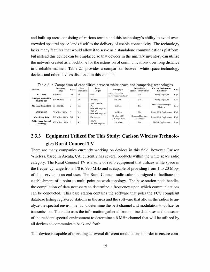
and built-up areas consisting of various terrain and this technology’s ability to avoid over-crowded spectral space lends itself to the delivery of usable connectivity. The technologylacks many features that would allow it to serve as a standalone communications platform,but instead this device can be emplaced so that devices in the military inventory can utilizethe network created as a backbone for the extension of communications over long distancein a reliable manner. Table 2.1 provides a comparison between white space technologydevices and other devices discussed in this chapter.
Table 2.1: Comparison of capabilities between white space and competing technologiesMedium Frequency
Range Layer Type 1Encryption
PowerOutput Throughput Adaptable to
Spectral EnvironmentCurrent Deployment/
Availability Cost
SATCOM 1-40 GHz 2/3 Yes variesvaries - dependenton resource availability No Widely Deployed High
Mil-Spec Radio (HF)AN/PRC-150 1.6 - 60 MHz 3 Yes 10W max 9.6 kbps No Widely Deployed Low
Mil-Spec Radio (FM) 30 - 88 MHz 3 Yes1 mW, 100mW,5 W,50 W with amplifier
16 kbps NoMost Widely Deployed
Platform Low
AN/PRC-117 30 MHz - 2 GHz 3 Yes10/20 W50 W with amplifier 10 Mbps No Limited Mil Deployment High
Wave Relay Suite 760 MHz - 5 GHz 2/3 No 5 W average41 Mbps UDP
31.1 Mbps TCPRequires Hardware
Exchange Limited Mil Deployment High
White Space SpectralTechnology 400 MHz - 1 GHz 2 No
100mW1 W with amplifier 1-16 Mbps Yes No Mil Deployment Low
2.3.3 Equipment Utilized For This Study: Carlson Wireless Technolo-gies Rural Connect TV
There are many companies currently working on devices in this field, however CarlsonWireless, based in Arcata, CA, currently has several products within the white space radiocategory. The Rural Connect TV is a suite of radio equipment that utilizes white space inthe frequency range from 470 to 790 MHz and is capable of providing from 1 to 20 Mbpsof data service to an end user. The Rural Connect radio suite is designed to facilitate theestablishment of a point to multi-point network topology. The base station node handlesthe compilation of data necessary to determine a frequency upon which communicationscan be conducted. This base station contains the software that polls the FCC compliantdatabase listing registered stations in the area and the software that allows the radios to an-alyze the spectral environment and determine the best channel and modulation to utilize fortransmission. The radio uses the information gathered from online databases and the scansof the resident spectral environment to determine a 6 MHz channel that will be utilized byall devices to communicate back and forth.
This device is capable of operating at several different modulations in order to ensure com-
15
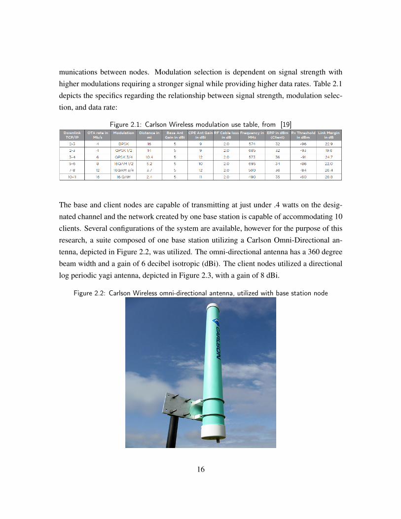
munications between nodes. Modulation selection is dependent on signal strength withhigher modulations requiring a stronger signal while providing higher data rates. Table 2.1depicts the specifics regarding the relationship between signal strength, modulation selec-tion, and data rate:
Figure 2.1: Carlson Wireless modulation use table, from [19]
The base and client nodes are capable of transmitting at just under .4 watts on the desig-nated channel and the network created by one base station is capable of accommodating 10clients. Several configurations of the system are available, however for the purpose of thisresearch, a suite composed of one base station utilizing a Carlson Omni-Directional an-tenna, depicted in Figure 2.2, was utilized. The omni-directional antenna has a 360 degreebeam width and a gain of 6 decibel isotropic (dBi). The client nodes utilized a directionallog periodic yagi antenna, depicted in Figure 2.3, with a gain of 8 dBi.
Figure 2.2: Carlson Wireless omni-directional antenna, utilized with base station node
16
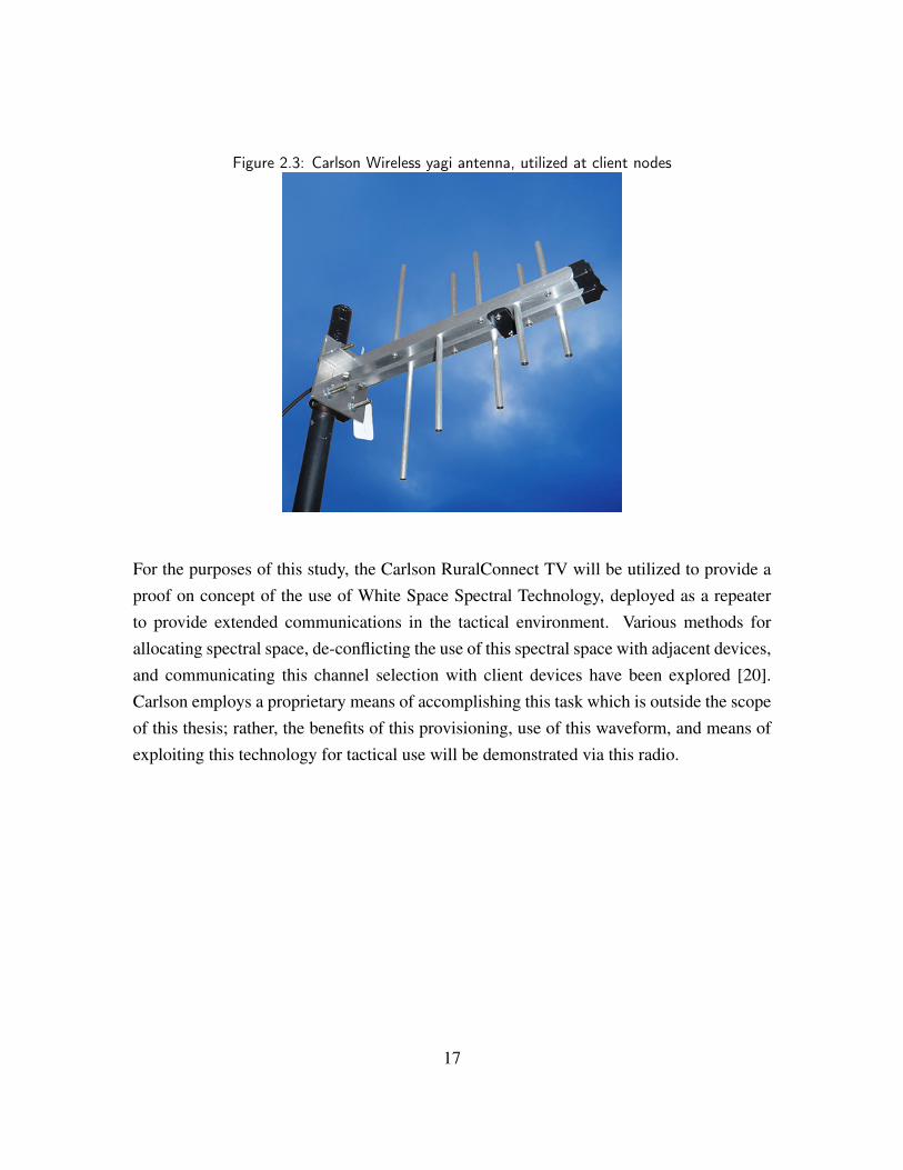
Figure 2.3: Carlson Wireless yagi antenna, utilized at client nodes
For the purposes of this study, the Carlson RuralConnect TV will be utilized to provide aproof on concept of the use of White Space Spectral Technology, deployed as a repeaterto provide extended communications in the tactical environment. Various methods forallocating spectral space, de-conflicting the use of this spectral space with adjacent devices,and communicating this channel selection with client devices have been explored [20].Carlson employs a proprietary means of accomplishing this task which is outside the scopeof this thesis; rather, the benefits of this provisioning, use of this waveform, and means ofexploiting this technology for tactical use will be demonstrated via this radio.
17

THIS PAGE INTENTIONALLY LEFT BLANK
18
CHAPTER 3:Methodology
Given a platform that promises to provide a solution to tactical, over the horizon, and highbandwidth communications, experimentation and analysis must be executed in order tovalidate the potential of this solution. In order to determine the viability of white spacespectral technology as a means of relaying communications in the tactical environment, itis necessary to examine the radio according to several criteria. Several lines of experimen-tation are necessary to determine if the radio is able to function in this environment andassess how this functionality compares to currently available military specification radios.
3.1 Experimentation GoalsThe essential criteria include several key characteristics that are vital to tactical commu-nications and the execution of the data hungry tasks that have become associated withmodern warfare. In this effort, the radio must be evaluated according to its suitability forthese tactical operations based on both performance and usability criteria.
Though the suite tested is not specifically designed for the purpose explored by this ex-perimentation, subjective criteria must be evaluated to determine if the potential for de-velopment to meet these specific requirements exists. To this end, equipment utilized inthis environment must be relatively lightweight and compact in order to be mobile. Thesemodern developments have also increased the space and mobility demands on tactical unitsand, in many cases, this equipment may need to be carried by a small group or transportedin a small military vehicle. The necessity for a large amount of equipment could be a hurdleto the overall usefulness of the system as a whole. It is possible that the base station sitemight be able to handle an increased amount of equipment as it relies on a reach back tothe Internet and would most likely be co-located with additional communications equip-ment. Client nodes must maintain a small signature, as these are the nodes that would bepushed to the forward lines of the communication infrastructure. Through the various linesof experimentation the size and mobility of the white space suite was evaluated.
Power consumption closely follows the footprint requirement. Power is a very limited
19
resource in the tactical environment. There are few sources available to power equipmenton the front lines of a conflict. The devices drawing power from a storage medium mustdraw a negligible amount of power in order to ensure that other devices essential to theexecution of tactical tasks are also able to draw power. These devices must use powerfrom a battery in an effective manner, meaning that commonly utilized military batteriesare able to power a device for a significant amount of time. In many cases, a piece ofcommunications equipment would be required to draw power over a long period of timeto facilitate communications. Due to these factors, the power draw of the system must beevaluated at all node types.
Ease of use is also essential to the operation of a communications platform. Speciallytrained personnel may not be available in the tactical environment and the provision of adevice that handles network establishment may reduce the personnel necessary to executefront line operations. This being the case, the speed and ease with which the network can beestablished, changed and adapted to the environment is essential to the overall evaluationof this suite.
Equipment that meets the above criteria is currently deployed throughout the military andthough this criterion is essential to tactical operations, the areas white space technologymight improve upon are more performance based in nature. Extensive analysis will be con-ducted to evaluate the throughput available utilizing the white space suite and the mannerthat various conditions affect this operation. In order to conduct these tests, several vari-ables will be changed in order to determine the effects on the system as a whole. Thesevariables include the terrain experiments were conducted on, the distance of the client nodesfrom the base station node, the number of client nodes, and the network topology.
The metrics chosen for evaluation were picked as a means to display the performance ofthe white space radio suite versus current military specification equipment and to displaythe potential, given continued development of the technology. These metrics included thethroughput experienced on the system, various measurements regarding the signal strengthshared between the radios, and the latency that is produced while executing various tasks.Furthermore, several experiments were conducted in order to determine if a task is possibleon this suite in order to establish a capability that might be valuable given continued de-velopment. The results of these experiments are not captured via measurements but rather
20
through the success or failure of the task.
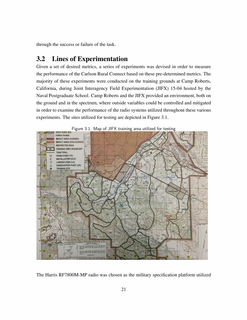
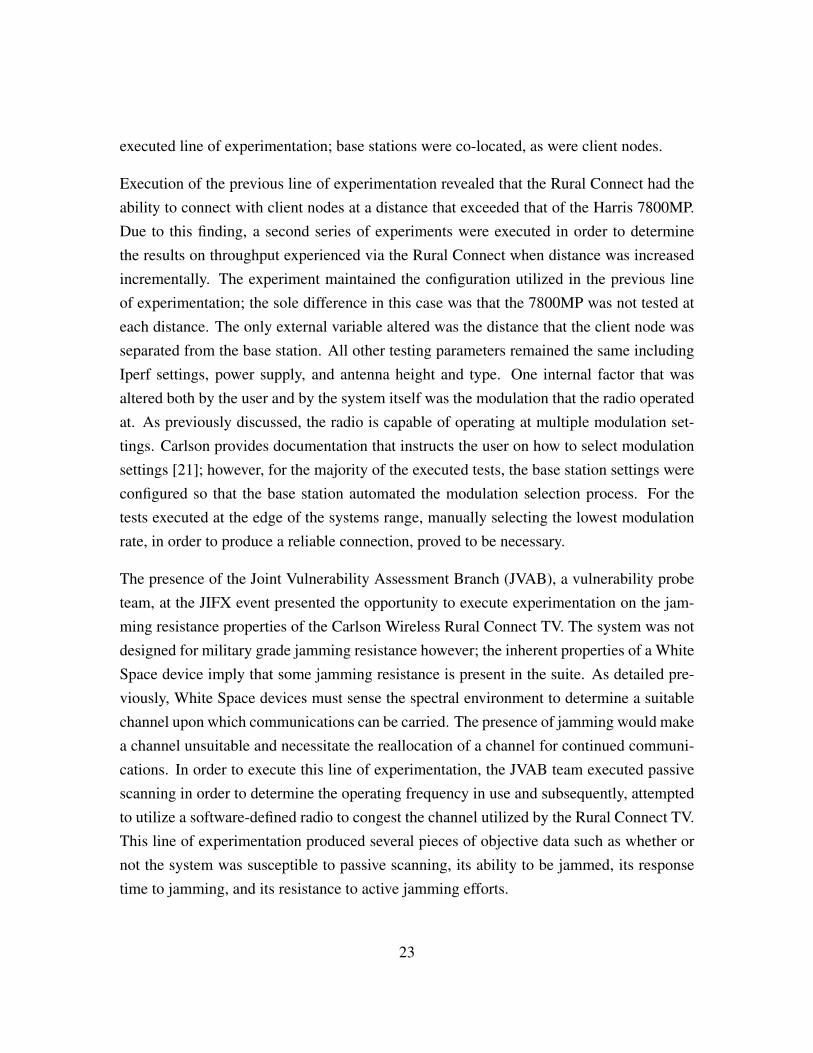
3.2 Lines of ExperimentationGiven a set of desired metrics, a series of experiments was devised in order to measurethe performance of the Carlson Rural Connect based on these pre-determined metrics. Themajority of these experiments were conducted on the training grounds at Camp Roberts,California, during Joint Interagency Field Experimentation (JIFX) 15-04 hosted by theNaval Postgraduate School. Camp Roberts and the JIFX provided an environment, both onthe ground and in the spectrum, where outside variables could be controlled and mitigatedin order to examine the performance of the radio systems utilized throughout these variousexperiments. The sites utilized for testing are depicted in Figure 3.1.
Figure 3.1: Map of JIFX training area utilized for testing
The Harris RF7800M-MP radio was chosen as the military specification platform utilized
21
for comparison to the Carlson Rural Connect suite. This radio mirrors the Harris 117Gin all features except that it does not support the ability to store Communications SecurityEncryption Keys (COMSEC). Since COMSEC was not utilized throughout the courseof the execution of this experimentation, this radio provided a means through which thewhite space suite could be compared to a radio recently fielded throughout the military,representing modern technology as discussed earlier.
The first series of experiments were conducted to establish a baseline for the performance ofthe two radio systems. These tests were all conducted over a short range in a very controlledenvironment. Data was not gathered during these tests for the purposes of comparing thetwo suites. Rather, data was gathered as a means to hypothesize on expected results duringthe larger field tests. These tests also provided an opportunity to utilize each radio suite anddetermine a set of “best practices” for use during testing. These best practices were utilizedto develop troubleshooting procedures and to ensure that each set of radios was operatingoptimally during the tests utilized for comparison.
The primary series of experiments consisted of two sets of tests designed to analyze therelationship between range and throughput in the white space radio, given tactical condi-tions. Iperf 2 was the tool chosen to evaluate the throughput available via each radio. Iperf,a commonly utilized network-testing tool, was configured to create a uni-directional TCPstream from a server, established at the base station of each radio suite, to a client, estab-lished at the client nodes of each radio suite. Testing was conducted after a connectionwas established between the base station and the client radio node as reported by the userinterface equipped on the radio device. The Harris 7800MP does not utilize a base sta-tion to client configuration, in this case, one radio was designated as the base station andco-located at the Carlson Rural Connect base station site.
The first set of experiments was conducted as a side-by-side comparison of the Carlson Ru-ral Connect and the Harris 7800 MP. Both radios were operated in as similar configurationswhere possible. The Harris radio obviously does not have the ability to change frequencyautomatically so a frequency close to that being operated on by Carlson Radio was cho-sen, 500 MHz in this case. All other variables were kept constant for each iteration of this
2https://iperf.fr
22
executed line of experimentation; base stations were co-located, as were client nodes.
Execution of the previous line of experimentation revealed that the Rural Connect had theability to connect with client nodes at a distance that exceeded that of the Harris 7800MP.Due to this finding, a second series of experiments were executed in order to determinethe results on throughput experienced via the Rural Connect when distance was increasedincrementally. The experiment maintained the configuration utilized in the previous lineof experimentation; the sole difference in this case was that the 7800MP was not tested ateach distance. The only external variable altered was the distance that the client node wasseparated from the base station. All other testing parameters remained the same includingIperf settings, power supply, and antenna height and type. One internal factor that wasaltered both by the user and by the system itself was the modulation that the radio operatedat. As previously discussed, the radio is capable of operating at multiple modulation set-tings. Carlson provides documentation that instructs the user on how to select modulationsettings [21]; however, for the majority of the executed tests, the base station settings wereconfigured so that the base station automated the modulation selection process. For thetests executed at the edge of the systems range, manually selecting the lowest modulationrate, in order to produce a reliable connection, proved to be necessary.
The presence of the Joint Vulnerability Assessment Branch (JVAB), a vulnerability probeteam, at the JIFX event presented the opportunity to execute experimentation on the jam-ming resistance properties of the Carlson Wireless Rural Connect TV. The system was notdesigned for military grade jamming resistance however; the inherent properties of a WhiteSpace device imply that some jamming resistance is present in the suite. As detailed pre-viously, White Space devices must sense the spectral environment to determine a suitablechannel upon which communications can be carried. The presence of jamming would makea channel unsuitable and necessitate the reallocation of a channel for continued communi-cations. In order to execute this line of experimentation, the JVAB team executed passivescanning in order to determine the operating frequency in use and subsequently, attemptedto utilize a software-defined radio to congest the channel utilized by the Rural Connect TV.This line of experimentation produced several pieces of objective data such as whether ornot the system was susceptible to passive scanning, its ability to be jammed, its responsetime to jamming, and its resistance to active jamming efforts.
23
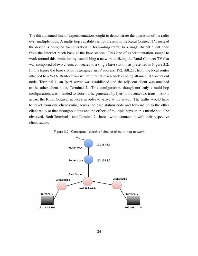
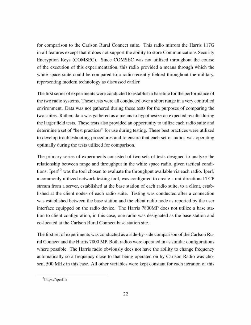
The third planned line of experimentation sought to demonstrate the operation of the radioover multiple hops. A multi- hop capability is not present in the Rural Connect TV, insteadthe device is designed for utilization in forwarding traffic to a single distant client nodefrom the Internet reach back at the base station. This line of experimentation sought towork around this limitation by establishing a network utilizing the Rural Connect TV thatwas composed of two clients connected to a single base station, as presented in Figure 3.2.In this figure the base station is assigned an IP address, 192.168.2.1, from the local routerattached to a WAN Router from which Internet reach back is being attained. At one clientnode, Terminal 1, an Iperf server was established and the adjacent client was attachedto the other client node, Terminal 2. This configuration, though not truly a multi-hopconfiguration, was intended to force traffic generated by Iperf to traverse two transmissionsacross the Rural Connect network in order to arrive at the server. The traffic would haveto travel from one client radio, across the base station node and forward on to the otherclient radio so that throughput data and the effects of multiple hops on this metric could beobserved. Both Terminal 1 and Terminal 2, share a wired connection with their respectiveclient radios.
Figure 3.2: Conceptual sketch of simulated multi-hop network
24
Following the results of the previous line of experimentation, a subsequent experimentwas devised to explore the routing scheme and the division of bandwidth utilized by theRural Connect suite. In order to explore these characteristics, an analysis between thethroughput of the system from the base station node to a single client was compared withthe throughput experienced when multiple nodes were transmitted to simultaneously. Datawas gathered by comparing the throughput of a network consisting of a base station witha co-located Iperf server and a client with a co-located Iperf client to the throughput of anetwork consisting of a similar setup, except for the addition of an additional Rural Connectclient and Iperf client. This data was then analyzed to determine if there was a significantor detectable difference in throughput when an additional client was added to the network.The purpose of this experiment was to gain an understanding of the bandwidth divisionthat takes place on the system as clients are added, in order to hypothesize on the effects onthroughput of a network with numerous nodes.
3.3 Equipment ConfigurationAll executed experiments shared a similar configuration in order to mitigate the introduc-tion of variables. The physical setup of equipment was composed in a manner that mitigatedits footprint and provided maximum mobility.
The Harris 7800MP radios were all operated in a MANPAC configuration with collapsiblewhip antennas. The MANPAC configuration allows the radio to be carried by a single in-dividual. The ANW2 waveform and configuration software was utilized to create a mobilenetwork between the radios to ensure the utilized frequency was 500 MHz. As discussedpreviously, ANW2C handles the connection between the radios as well as the networkaddressing, via DHCP, and routing. Power was provisioned to the radios using BA-5590rechargeable batteries.
The Rural Connect, having not been developed for military use, allowed for a much morevariable configuration. For the purpose of the lines of experimentation described above, astandard configuration was employed. Antennas were all mounted on portable 2-3 metervariable masts. The client radios were also mounted to the masts with the directional yagiantennas. The base station for the system is designed to be rack mounted. In order to utilizeit in a tactical environment, a small rack was fashioned to house the radio as depicted in
25
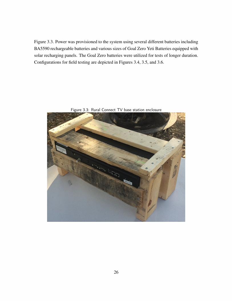
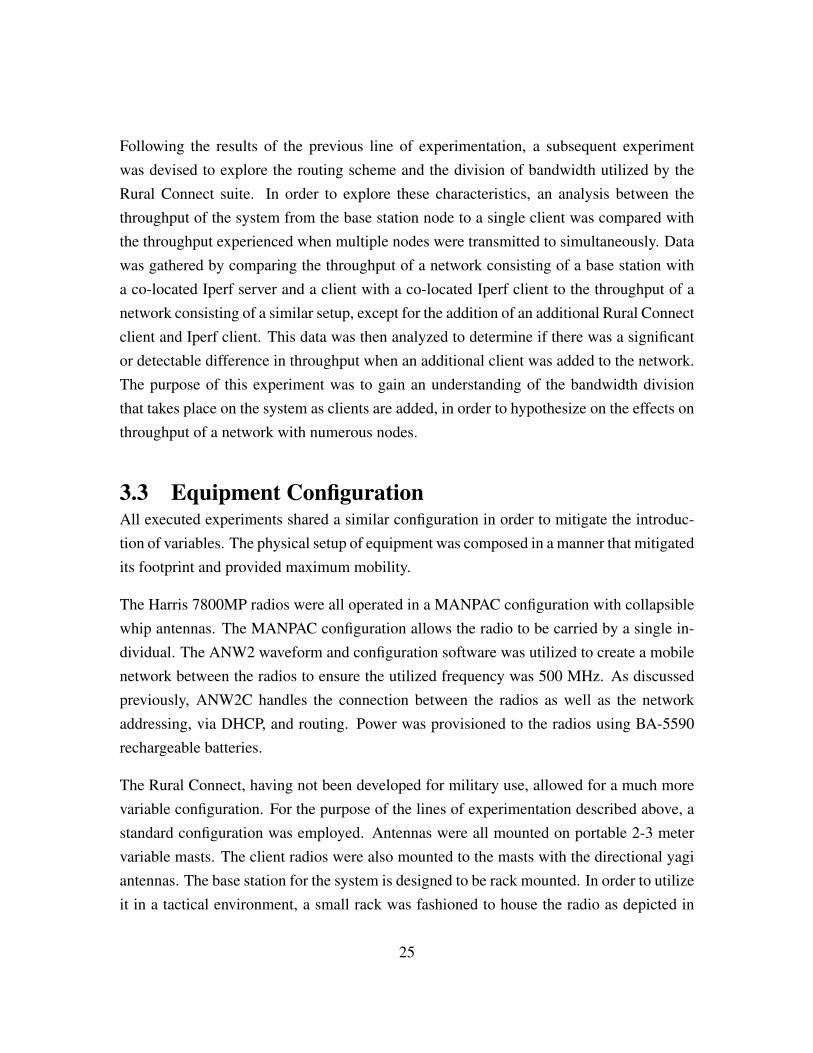
Figure 3.3. Power was provisioned to the system using several different batteries includingBA5590 rechargeable batteries and various sizes of Goal Zero Yeti Batteries equipped withsolar recharging panels. The Goal Zero batteries were utilized for tests of longer duration.Configurations for field testing are depicted in Figures 3.4, 3.5, and 3.6.
Figure 3.3: Rural Connect TV base station enclosure
26
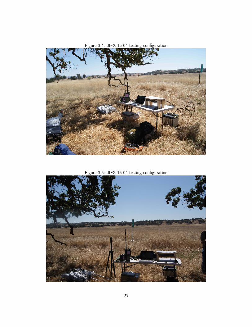
Figure 3.4: JIFX 15-04 testing configuration
Figure 3.5: JIFX 15-04 testing configuration
27
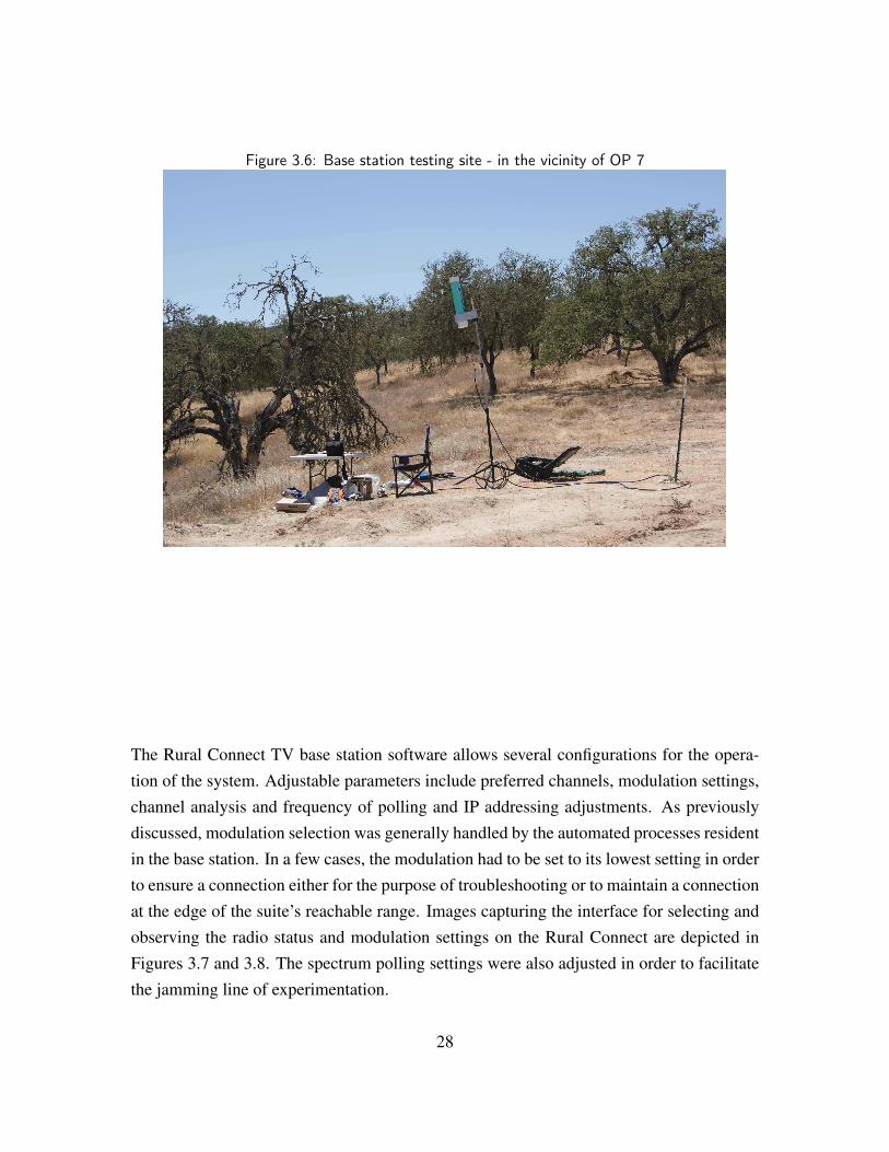
Figure 3.6: Base station testing site - in the vicinity of OP 7
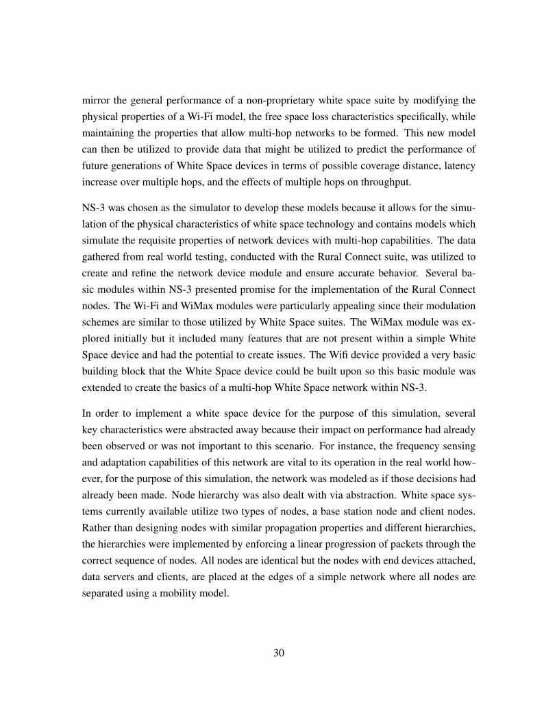
The Rural Connect TV base station software allows several configurations for the opera-tion of the system. Adjustable parameters include preferred channels, modulation settings,channel analysis and frequency of polling and IP addressing adjustments. As previouslydiscussed, modulation selection was generally handled by the automated processes residentin the base station. In a few cases, the modulation had to be set to its lowest setting in orderto ensure a connection either for the purpose of troubleshooting or to maintain a connectionat the edge of the suite’s reachable range. Images capturing the interface for selecting andobserving the radio status and modulation settings on the Rural Connect are depicted inFigures 3.7 and 3.8. The spectrum polling settings were also adjusted in order to facilitatethe jamming line of experimentation.
28
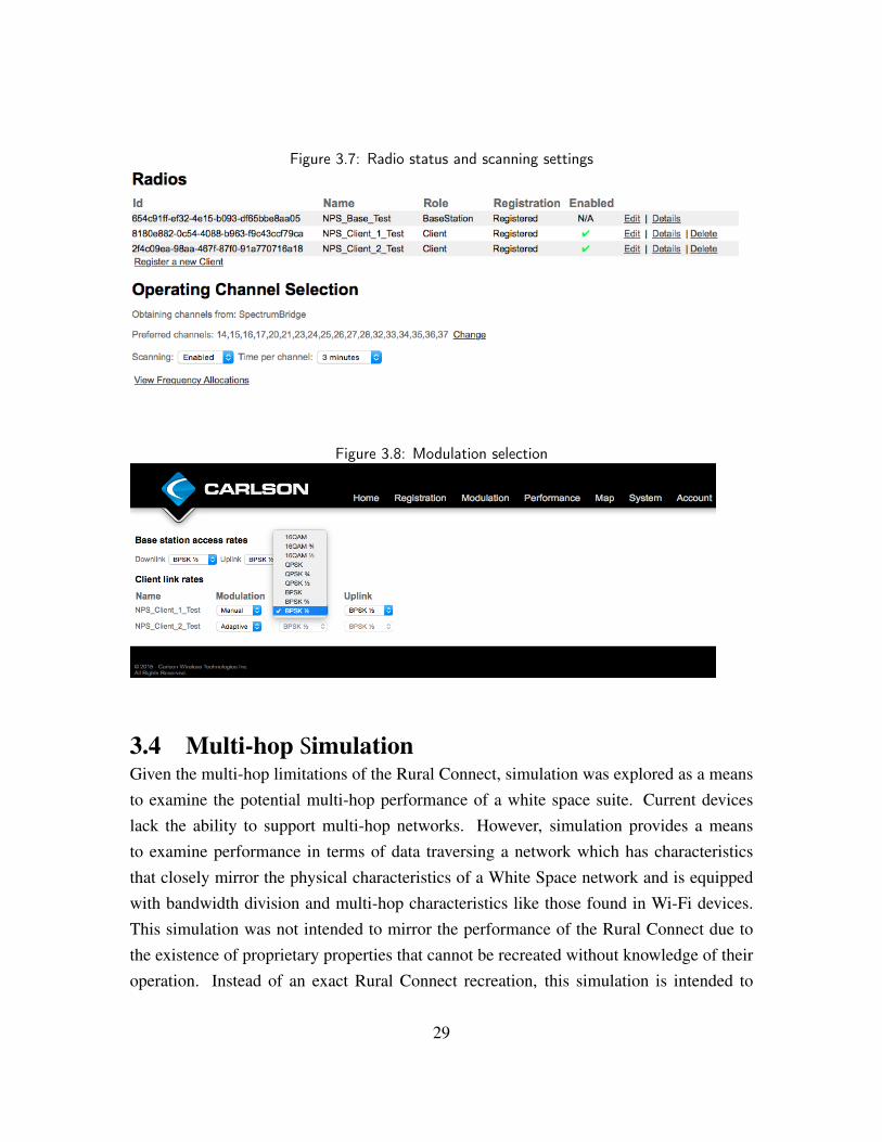
Figure 3.7: Radio status and scanning settings
Figure 3.8: Modulation selection
3.4 Multi-hop SimulationGiven the multi-hop limitations of the Rural Connect, simulation was explored as a meansto examine the potential multi-hop performance of a white space suite. Current deviceslack the ability to support multi-hop networks. However, simulation provides a meansto examine performance in terms of data traversing a network which has characteristicsthat closely mirror the physical characteristics of a White Space network and is equippedwith bandwidth division and multi-hop characteristics like those found in Wi-Fi devices.This simulation was not intended to mirror the performance of the Rural Connect due tothe existence of proprietary properties that cannot be recreated without knowledge of theiroperation. Instead of an exact Rural Connect recreation, this simulation is intended to
29
mirror the general performance of a non-proprietary white space suite by modifying thephysical properties of a Wi-Fi model, the free space loss characteristics specifically, whilemaintaining the properties that allow multi-hop networks to be formed. This new modelcan then be utilized to provide data that might be utilized to predict the performance offuture generations of White Space devices in terms of possible coverage distance, latencyincrease over multiple hops, and the effects of multiple hops on throughput.
NS-3 was chosen as the simulator to develop these models because it allows for the simu-lation of the physical characteristics of white space technology and contains models whichsimulate the requisite properties of network devices with multi-hop capabilities. The datagathered from real world testing, conducted with the Rural Connect suite, was utilized tocreate and refine the network device module and ensure accurate behavior. Several ba-sic modules within NS-3 presented promise for the implementation of the Rural Connectnodes. The Wi-Fi and WiMax modules were particularly appealing since their modulationschemes are similar to those utilized by White Space suites. The WiMax module was ex-plored initially but it included many features that are not present within a simple WhiteSpace device and had the potential to create issues. The Wifi device provided a very basicbuilding block that the White Space device could be built upon so this basic module wasextended to create the basics of a multi-hop White Space network within NS-3.
In order to implement a white space device for the purpose of this simulation, severalkey characteristics were abstracted away because their impact on performance had alreadybeen observed or was not important to this scenario. For instance, the frequency sensingand adaptation capabilities of this network are vital to its operation in the real world how-ever, for the purpose of this simulation, the network was modeled as if those decisions hadalready been made. Node hierarchy was also dealt with via abstraction. White space sys-tems currently available utilize two types of nodes, a base station node and client nodes.Rather than designing nodes with similar propagation properties and different hierarchies,the hierarchies were implemented by enforcing a linear progression of packets through thecorrect sequence of nodes. All nodes are identical but the nodes with end devices attached,data servers and clients, are placed at the edges of a simple network where all nodes areseparated using a mobility model.
30
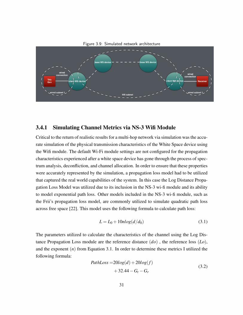
Figure 3.9: Simulated network architecture
3.4.1 Simulating Channel Metrics via NS-3 Wifi Module
Critical to the return of realistic results for a multi-hop network via simulation was the accu-rate simulation of the physical transmission characteristics of the White Space device usingthe Wifi module. The default Wi-Fi module settings are not configured for the propagationcharacteristics experienced after a white space device has gone through the process of spec-trum analysis, deconfliction, and channel allocation. In order to ensure that these propertieswere accurately represented by the simulation, a propagation loss model had to be utilizedthat captured the real world capabilities of the system. In this case the Log Distance Propa-gation Loss Model was utilized due to its inclusion in the NS-3 wi-fi module and its abilityto model exponential path loss. Other models included in the NS-3 wi-fi module, such asthe Frii’s propagation loss model, are commonly utilized to simulate quadratic path lossacross free space [22]. This model uses the following formula to calculate path loss:
L = L0 +10nlog(d/d0) (3.1)
The parameters utilized to calculate the characteristics of the channel using the Log Dis-tance Propagation Loss module are the reference distance (do) , the reference loss (Lo),and the exponent (n) from Equation 3.1. In order to determine these metrics I utilized thefollowing formula:
PathLoss =20log(d)+20log( f )
+32.44−Gt −Gr(3.2)
31
This left only the selection of an operating frequency, a reference distance, and the gainof two antennas in order to calculate the reference loss. A transmission frequency that fellwithin the range utilized by a White Space system, 500 MHz, was utilized as the frequencyfor this simulation. A receiver and transmitter gain of 10 dB, a close approximation ofthe Rural Connect system’s antenna specifications, was also utilized to compute the FreeSpace Loss. These numbers are both realistic and reflect real world experience duringtesting for this system. A distance of 10 meters was utilized as the reference distance, forthe purpose of computing a reference Free Space Loss exponent, resulting in a referenceloss of -26.4 dB. In order to calculate the exponent, a second reference distance, 100 m, andloss were calculated and plugged into Equation 1. This allowed the value of n to be foundvia some simple algebra. The exponent value of 1.998 was utilized as a baseline for theconstruction of the model. A further analysis of loss was conducted given the data gatheredby real world testing and adjustments were made to this exponent in order to reproduceexperienced results in a single hop. These factors combined resulted in the production offigures that effectively modeled the physical performance of a White Space suite with theadded inclusion of Wifi-like multi-hop capabilities [23].
3.4.2 TestingTwo methods were utilized to test and evaluate the simulated White Space network. TheUser Datagram Protocol (UDP) Echo Server was utilized primarily to test the routing acrossthe network and also to evaluate latency across the network as the distance between WhiteSpace nodes was varied between 500 and 7000 meters. The model was setup to send 5pings across the network at one-second intervals. Measurements were taken using pcapcaptures which were also utilized to ensure that all White Space nodes were contributingto the transmission of the packet.
Ping tests facilitated the detection of errors within the simulation. Several issues withthe simulation were discovered following the execution of ping testing. The first was thenecessity to utilize the Wifi modules Ad Hoc feature. This feature enabled the convergenceof the network and allowed some traffic to be forwarded to several nodes. The secondissue encountered was the presence of an Address Resolution Protocol (ARP) request issuethat seems to affect certain Wifi configurations within NS-3. In order to circumvent thisissue, the ARP cache for each node was pre-populated before the simulation was initiated.
32
After these issues were remedied, ping testing was utilized to confirm that the network wasfunctioning normally and to get a baseline for expected latency.
Throughput testing was conducted utilizing several functions designed to transmit 2 millionbytes across the network. Again, pcap captures were utilized to ensure that the data prop-erly traversed the network and that all necessary links performed as expected. Testing wasconducted to determine the viable node separation distances and the associated throughputfor the system. Throughput testing was utilized to determine the range achievable by amulti-hop system as a whole and the effects of these hops on the latency and data rate ofthe system. The results of these tests were utilized to hypothesize regarding the real worldperformance of the white space devices utilized given the case that the construction of amulti-hop network was possible.
33

THIS PAGE INTENTIONALLY LEFT BLANK
34
CHAPTER 4:Findings
Testing conducted at JIFX 15-04 and in a laboratory environment produced a great deal ofdata for analysis. Though the majority of these findings took the form of performance mea-surements, a significant amount of data was gathered regarding the subjective performanceof the platform.
Subjective data was covered via notes recorded and collected from testing personnel. Thetesting team at JIFX 15-04 consisted of 3 personnel, all familiar with military radio systems.All personnel provided feedback based on the criteria established in Chapter 3 for lateranalysis. Findings in this area are particularly focused on the Carlson RuralConnect TVsuite since the military specification compliant radio, the Harris 7800MP in this case, isdesigned for tactical employment. Users evaluated the Carlson Rural Connect’s potentialfor tactical employment and noted any major hindrances encountered.
Performance data was compiled over the course of numerous iterations of testing as detailedin Chapter 3. In the case of the planned multi-hop network tests, inconclusive data wasgathered. This resulted in additional research and testing. For all other tests, data wasrecorded significant to execution. This data includes configuration, significant settings,errors encountered, results and location specifics. The major testing locations utilized forthe majority of the experiments executed at JIFX 15-04 can be located in the Table 4.1.
Table 4.1: JIFX 15-04 testing locations and significant radio settingsTest Site Grid Location (MGRS) Distance from Base Station RuralConnect ModulationBase 10S FE 97723 58573 N/A N/A1 10S FE 98130 59528 1.2 KM QPSK3/4; 16QAM2 10S FE 99006 60487 2.3 KM QPSK3/4; 16QAM3 10S FE 99868 62001 4 KM QPSK3/4; 16QAM4 10S GE 01353 61169 4.7 KM QPSK3/4; 16QAM5 10S GE 03239 60258 5.8 KM BPSK1/26 10S GE 04350 59762 6.2 KM N/A
35
4.1 Employment Potential
The Carlson RuralConnect TV is not specifically designed for mobility or durability undermobile use. However, after several modifications to the manufacturer’s installation instruc-tions, a platform for mobile employment was devised. No major modifications were madeto the equipment however, some mounting and employment recommendations were notfeasible for testing. Specifically, antenna mount height had to be reduced approximately 1-2 meters from the manufacturer’s recommendations of between 4 and 6 meters, resulting ina deployment height of approximately 3.5 meters. The size and weight of the antennas didnot allow for a practical or safe deployment at the recommended height utilizing mobileantenna masts. This was particularly true of the base station’s omni directional antenna.The manufacturer states that mounting the antenna at this height might have noticeable im-pact on performance and presented Figures 4.1 and 4.2 as a reference for deployments inuse given adherence to manufacturers recommendations. The graphs display the change inelevation, represented by the y axis, versus the distance between the base station and clientradio, represented by the x axis. These figures depict the potential propagation potential,both in terms of distance and elevation change, of the radio given a refined deployment. Ineach of these deployments, a steady throughput rate of 2-4 Mbps was achieved, over twicethe distance achieved in this experiment.
Figure 4.1: Profile 1 of Carlson Wireless install of Rural Connect system - manufacturer em-placement
36
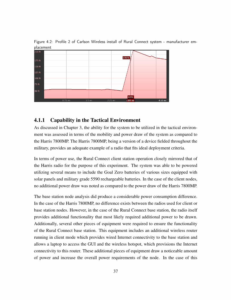
Figure 4.2: Profile 2 of Carlson Wireless install of Rural Connect system - manufacturer em-placement
4.1.1 Capability in the Tactical EnvironmentAs discussed in Chapter 3, the ability for the system to be utilized in the tactical environ-ment was assessed in terms of the mobility and power draw of the system as compared tothe Harris 7800MP. The Harris 7800MP, being a version of a device fielded throughout themilitary, provides an adequate example of a radio that fits ideal deployment criteria.
In terms of power use, the Rural Connect client station operation closely mirrored that ofthe Harris radio for the purpose of this experiment. The system was able to be poweredutilizing several means to include the Goal Zero batteries of various sizes equipped withsolar panels and military grade 5590 rechargeable batteries. In the case of the client nodes,no additional power draw was noted as compared to the power draw of the Harris 7800MP.
The base station node analysis did produce a considerable power consumption difference.In the case of the Harris 7800MP, no difference exists between the radios used for client orbase station nodes. However, in the case of the Rural Connect base station, the radio itselfprovides additional functionality that most likely required additional power to be drawn.Additionally, several other pieces of equipment were required to ensure the functionalityof the Rural Connect base station. This equipment includes an additional wireless routerrunning in client mode which provides wired Internet connectivity to the base station andallows a laptop to access the GUI and the wireless hotspot, which provisions the Internetconnectivity to this router. These additional pieces of equipment draw a noticeable amountof power and increase the overall power requirements of the node. In the case of this
37
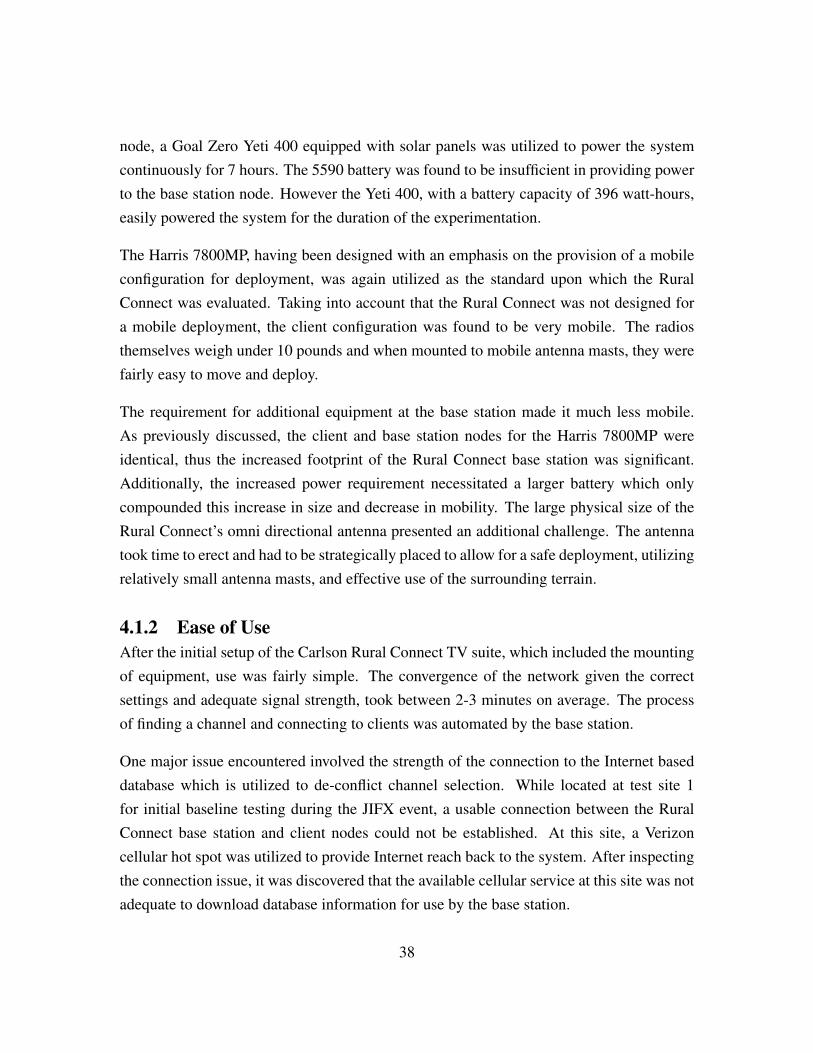
node, a Goal Zero Yeti 400 equipped with solar panels was utilized to power the systemcontinuously for 7 hours. The 5590 battery was found to be insufficient in providing powerto the base station node. However the Yeti 400, with a battery capacity of 396 watt-hours,easily powered the system for the duration of the experimentation.
The Harris 7800MP, having been designed with an emphasis on the provision of a mobileconfiguration for deployment, was again utilized as the standard upon which the RuralConnect was evaluated. Taking into account that the Rural Connect was not designed fora mobile deployment, the client configuration was found to be very mobile. The radiosthemselves weigh under 10 pounds and when mounted to mobile antenna masts, they werefairly easy to move and deploy.
The requirement for additional equipment at the base station made it much less mobile.As previously discussed, the client and base station nodes for the Harris 7800MP wereidentical, thus the increased footprint of the Rural Connect base station was significant.Additionally, the increased power requirement necessitated a larger battery which onlycompounded this increase in size and decrease in mobility. The large physical size of theRural Connect’s omni directional antenna presented an additional challenge. The antennatook time to erect and had to be strategically placed to allow for a safe deployment, utilizingrelatively small antenna masts, and effective use of the surrounding terrain.
4.1.2 Ease of UseAfter the initial setup of the Carlson Rural Connect TV suite, which included the mountingof equipment, use was fairly simple. The convergence of the network given the correctsettings and adequate signal strength, took between 2-3 minutes on average. The processof finding a channel and connecting to clients was automated by the base station.
One major issue encountered involved the strength of the connection to the Internet baseddatabase which is utilized to de-conflict channel selection. While located at test site 1for initial baseline testing during the JIFX event, a usable connection between the RuralConnect base station and client nodes could not be established. At this site, a Verizoncellular hot spot was utilized to provide Internet reach back to the system. After inspectingthe connection issue, it was discovered that the available cellular service at this site was notadequate to download database information for use by the base station.
38

This is the result of a restriction placed on the hardware by the manufacturer in order toadhere to FCC requirements. The radios themselves are not reliant on the database in orderto establish a connection. The connection, in terms of addressing and forwarding of infor-mation on the Rural Connect, is handled by a weightless link layer protocol as depicted inFigure 4.4. This protocol is non-reliant on Dynamic Host Configuration Protocol (DHCP),but rather utilizes an addressing scheme programmed into the radios. Under fully function-ing conditions, the base station designates a channel for communication, the client radioscycle through their frequency range until a base station beacon is found, and once located,they attempt to connect to it. If the base station is associated with a particular client radioit will be allowed to connect. The base station’s set of associated client radios was pre-configured into the Rural Connect software by the manufacturer on the system utilized fortesting. The lack of connection experienced during experimentation represents an inabilityfor the radios to register, meaning that the database is unavailable for de-confliction be-tween the channel the base station has selected for use and the channels in use within thecurrent location. In this case, the base station’s operating channel cannot be selected andthus the client radios are unable to register with the base station.
It is possible to operate the Rural Connect without the ability to access the on-line database.Enabling this capability involves coordinating the location of use with the FCC. For the pur-pose of this test, and for stateside military use of the radio, this is not practical. Moving thesuite would invalidate this coordination and could either result in interference or improperfunctioning of the radio equipment.
4.1.3 Passive Scanning and JammingPassive scans were conducted by a third party, the JVAB team, with the intent of discover-ing the operating frequency of the Rural Connect Radio. These scans were conducted fromthe client node, base station, and intermediate locations. In each case the scans were ableto detect a significant spike in activity on the channel being utilized by the Rural Connectnetwork. The majority of the scans were conducted at times when no significant data wasbeing sent, by users, across the network. Regardless of data transmissions the operatingfrequency of the network was able to be accurately detected by passive scanning.
39
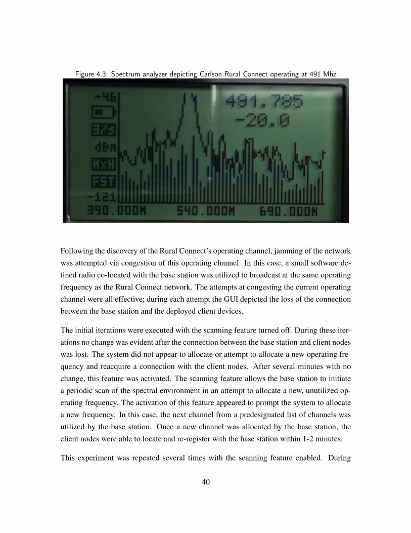
Figure 4.3: Spectrum analyzer depicting Carlson Rural Connect operating at 491 Mhz
Following the discovery of the Rural Connect’s operating channel, jamming of the networkwas attempted via congestion of this operating channel. In this case, a small software de-fined radio co-located with the base station was utilized to broadcast at the same operatingfrequency as the Rural Connect network. The attempts at congesting the current operatingchannel were all effective; during each attempt the GUI depicted the loss of the connectionbetween the base station and the deployed client devices.
The initial iterations were executed with the scanning feature turned off. During these iter-ations no change was evident after the connection between the base station and client nodeswas lost. The system did not appear to allocate or attempt to allocate a new operating fre-quency and reacquire a connection with the client nodes. After several minutes with nochange, this feature was activated. The scanning feature allows the base station to initiatea periodic scan of the spectral environment in an attempt to allocate a new, unutilized op-erating frequency. The activation of this feature appeared to prompt the system to allocatea new frequency. In this case, the next channel from a predesignated list of channels wasutilized by the base station. Once a new channel was allocated by the base station, theclient nodes were able to locate and re-register with the base station within 1-2 minutes.
This experiment was repeated several times with the scanning feature enabled. During
40
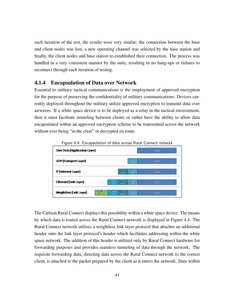
each iteration of the test, the results were very similar; the connection between the baseand client nodes was lost, a new operating channel was selected by the base station andfinally, the client nodes and base station re-established their connection. The process washandled in a very consistent manner by the suite, resulting in no hang-ups or failures toreconnect through each iteration of testing.
4.1.4 Encapsulation of Data over NetworkEssential to military tactical communications is the employment of approved encryptionfor the purpose of preserving the confidentiality of military communications. Devices cur-rently deployed throughout the military utilize approved encryption to transmit data overairwaves. If a white space device is to be deployed as a relay in the tactical environment,then it must facilitate tunneling between clients or rather have the ability to allow dataencapsulated within an approved encryption scheme to be transmitted across the networkwithout ever being “in the clear” or decrypted en route.
Figure 4.4: Encapsulation of data across Rural Connect network
The Carlson Rural Connect displays this possibility within a white space device. The meansby which data is routed across the Rural Connect network is displayed in Figure 4.4. TheRural Connect network utilizes a weightless link layer protocol that attaches an additionalheader onto the link layer protocol’s header which facilitates addressing within the whitespace network. The addition of this header is utilized only by Rural Connect hardware forforwarding purposes and provides seamless tunneling of data through the network. Therequisite forwarding data, directing data across the Rural Connect network to the correctclient, is attached to the packet prepared by the client as it enters the network. Data within
41
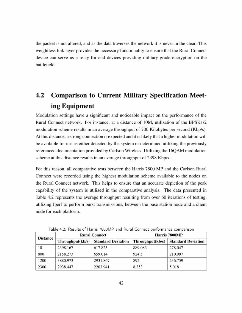
the packet is not altered, and as the data traverses the network it is never in the clear. Thisweightless link layer provides the necessary functionality to ensure that the Rural Connectdevice can serve as a relay for end devices providing military grade encryption on thebattlefield.
4.2 Comparison to Current Military Specification Meet-ing Equipment
Modulation settings have a significant and noticeable impact on the performance of theRural Connect network. For instance, at a distance of 10M, utilization of the BPSK1/2modulation scheme results in an average throughput of 700 Kilobytes per second (Kbp/s).At this distance, a strong connection is expected and it is likely that a higher modulation willbe available for use as either detected by the system or determined utilizing the previouslyreferenced documentation provided by Carlson Wireless. Utilizing the 16QAM modulationscheme at this distance results in an average throughput of 2398 Kbp/s.
For this reason, all comparative tests between the Harris 7800 MP and the Carlson RuralConnect were recorded using the highest modulation scheme available to the nodes onthe Rural Connect network. This helps to ensure that an accurate depiction of the peakcapability of the system is utilized in the comparative analysis. The data presented inTable 4.2 represents the average throughput resulting from over 60 iterations of testing,utilizing Iperf to perform burst transmissions, between the base station node and a clientnode for each platform.
Table 4.2: Results of Harris 7800MP and Rural Connect performance comparison
DistanceRural Connect Harris 7800MP
Throughput(kb/s) Standard Deviation Throughput(kb/s) Standard Deviation10 2398.167 617.825 889.083 278.047
800 2158.273 659.014 924.5 210.097
1200 3880.973 2931.867 892 236.759
2300 2938.447 2203.941 8.353 5.018
42
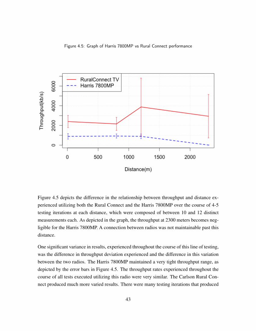
Figure 4.5: Graph of Harris 7800MP vs Rural Connect performance
Figure 4.5 depicts the difference in the relationship between throughput and distance ex-perienced utilizing both the Rural Connect and the Harris 7800MP over the course of 4-5testing iterations at each distance, which were composed of between 10 and 12 distinctmeasurements each. As depicted in the graph, the throughput at 2300 meters becomes neg-ligible for the Harris 7800MP. A connection between radios was not maintainable past thisdistance.
One significant variance in results, experienced throughout the course of this line of testing,was the difference in throughput deviation experienced and the difference in this variationbetween the two radios. The Harris 7800MP maintained a very tight throughput range, asdepicted by the error bars in Figure 4.5. The throughput rates experienced throughout thecourse of all tests executed utilizing this radio were very similar. The Carlson Rural Con-nect produced much more varied results. There were many testing iterations that produced
43
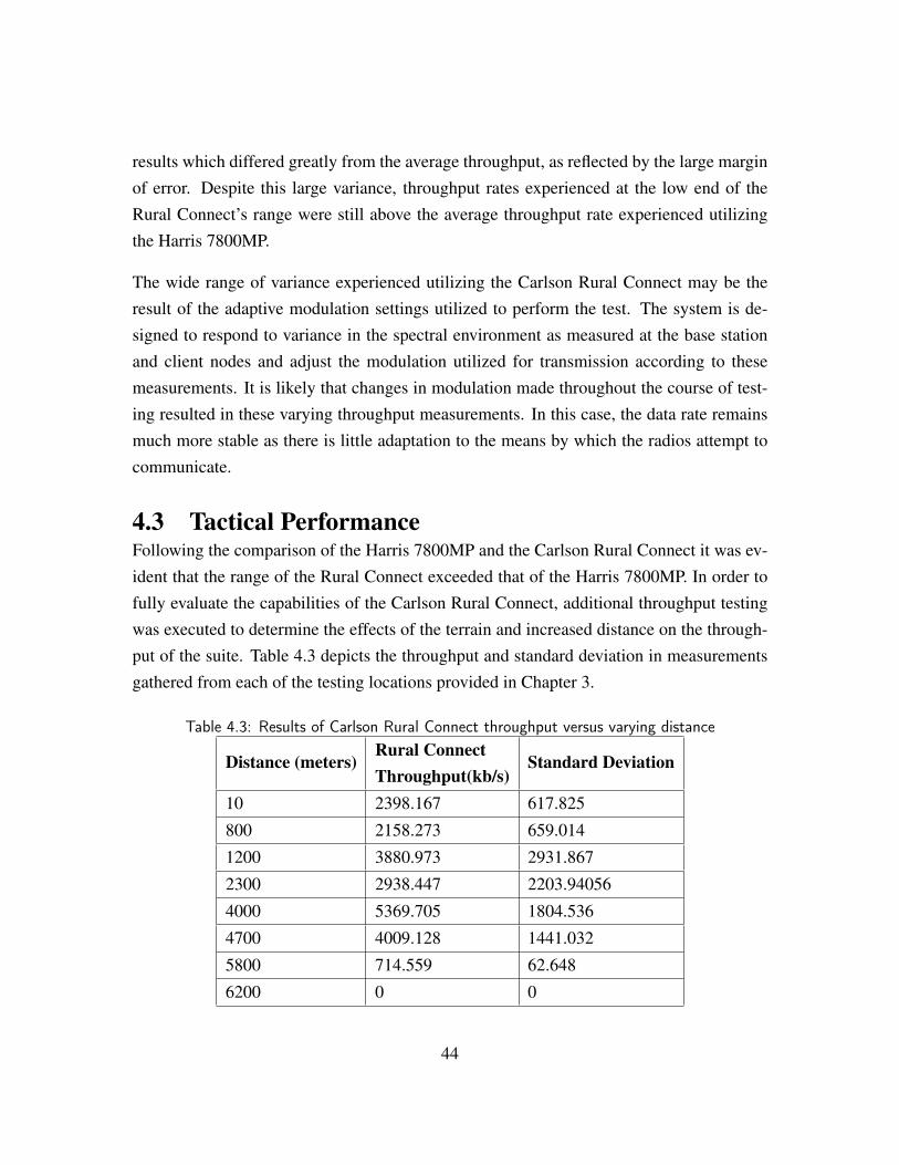
results which differed greatly from the average throughput, as reflected by the large marginof error. Despite this large variance, throughput rates experienced at the low end of theRural Connect’s range were still above the average throughput rate experienced utilizingthe Harris 7800MP.
The wide range of variance experienced utilizing the Carlson Rural Connect may be theresult of the adaptive modulation settings utilized to perform the test. The system is de-signed to respond to variance in the spectral environment as measured at the base stationand client nodes and adjust the modulation utilized for transmission according to thesemeasurements. It is likely that changes in modulation made throughout the course of test-ing resulted in these varying throughput measurements. In this case, the data rate remainsmuch more stable as there is little adaptation to the means by which the radios attempt tocommunicate.
4.3 Tactical PerformanceFollowing the comparison of the Harris 7800MP and the Carlson Rural Connect it was ev-ident that the range of the Rural Connect exceeded that of the Harris 7800MP. In order tofully evaluate the capabilities of the Carlson Rural Connect, additional throughput testingwas executed to determine the effects of the terrain and increased distance on the through-put of the suite. Table 4.3 depicts the throughput and standard deviation in measurementsgathered from each of the testing locations provided in Chapter 3.
Table 4.3: Results of Carlson Rural Connect throughput versus varying distance
Distance (meters)Rural ConnectThroughput(kb/s)
Standard Deviation
10 2398.167 617.825
800 2158.273 659.014
1200 3880.973 2931.867
2300 2938.447 2203.94056
4000 5369.705 1804.536
4700 4009.128 1441.032
5800 714.559 62.648
6200 0 0
44
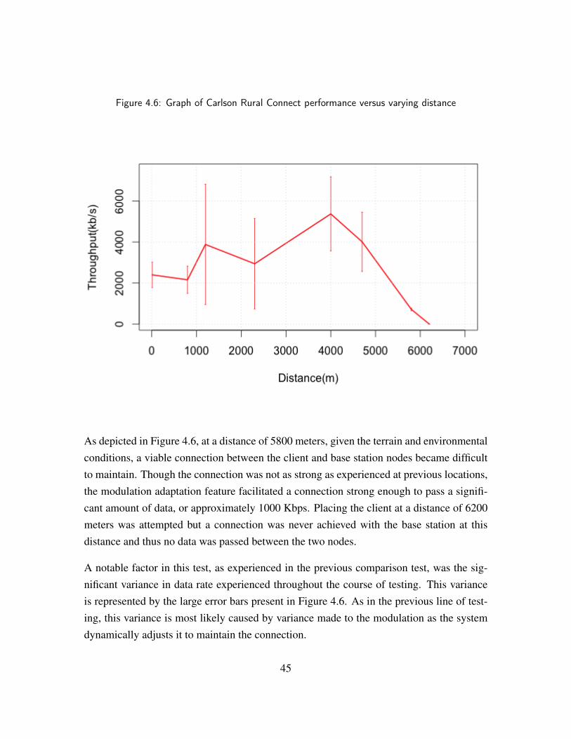
Figure 4.6: Graph of Carlson Rural Connect performance versus varying distance
As depicted in Figure 4.6, at a distance of 5800 meters, given the terrain and environmentalconditions, a viable connection between the client and base station nodes became difficultto maintain. Though the connection was not as strong as experienced at previous locations,the modulation adaptation feature facilitated a connection strong enough to pass a signifi-cant amount of data, or approximately 1000 Kbps. Placing the client at a distance of 6200meters was attempted but a connection was never achieved with the base station at thisdistance and thus no data was passed between the two nodes.
A notable factor in this test, as experienced in the previous comparison test, was the sig-nificant variance in data rate experienced throughout the course of testing. This varianceis represented by the large error bars present in Figure 4.6. As in the previous line of test-ing, this variance is most likely caused by variance made to the modulation as the systemdynamically adjusts it to maintain the connection.
45
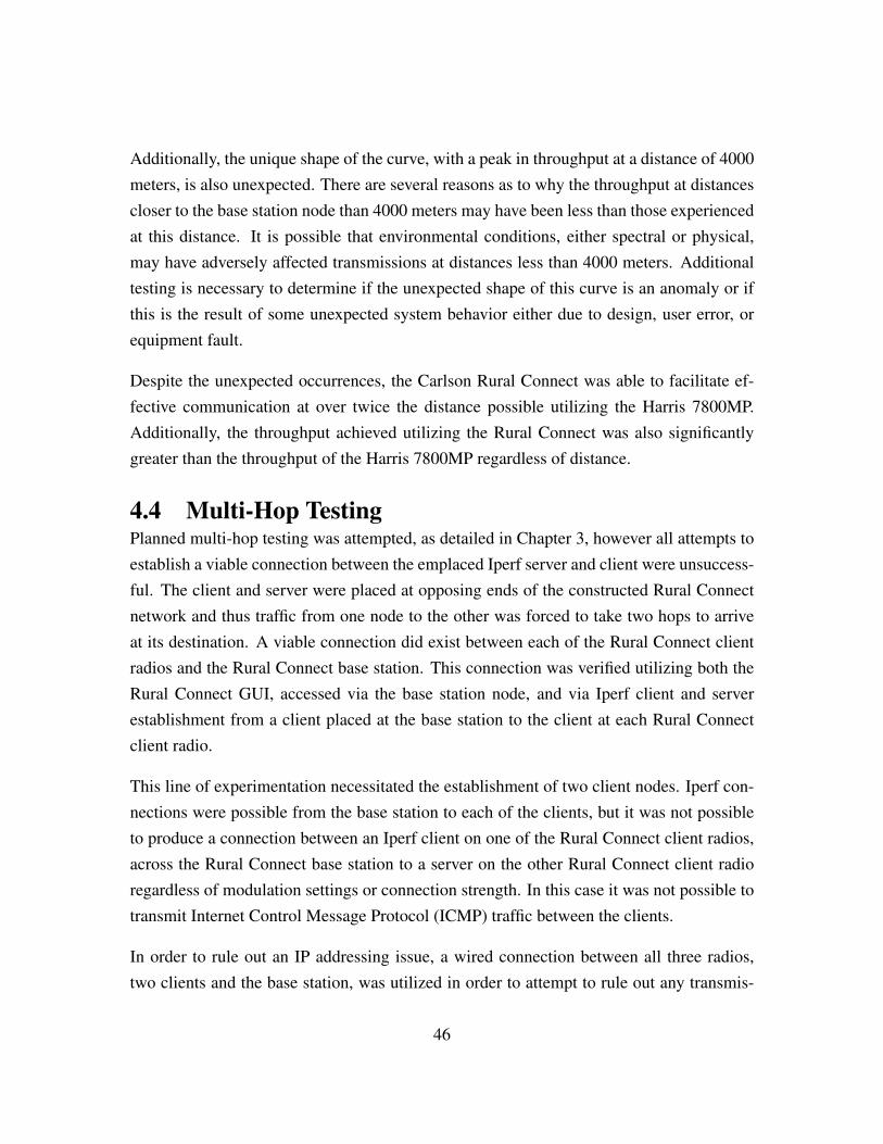
Additionally, the unique shape of the curve, with a peak in throughput at a distance of 4000meters, is also unexpected. There are several reasons as to why the throughput at distancescloser to the base station node than 4000 meters may have been less than those experiencedat this distance. It is possible that environmental conditions, either spectral or physical,may have adversely affected transmissions at distances less than 4000 meters. Additionaltesting is necessary to determine if the unexpected shape of this curve is an anomaly or ifthis is the result of some unexpected system behavior either due to design, user error, orequipment fault.
Despite the unexpected occurrences, the Carlson Rural Connect was able to facilitate ef-fective communication at over twice the distance possible utilizing the Harris 7800MP.Additionally, the throughput achieved utilizing the Rural Connect was also significantlygreater than the throughput of the Harris 7800MP regardless of distance.
4.4 Multi-Hop TestingPlanned multi-hop testing was attempted, as detailed in Chapter 3, however all attempts toestablish a viable connection between the emplaced Iperf server and client were unsuccess-ful. The client and server were placed at opposing ends of the constructed Rural Connectnetwork and thus traffic from one node to the other was forced to take two hops to arriveat its destination. A viable connection did exist between each of the Rural Connect clientradios and the Rural Connect base station. This connection was verified utilizing both theRural Connect GUI, accessed via the base station node, and via Iperf client and serverestablishment from a client placed at the base station to the client at each Rural Connectclient radio.
This line of experimentation necessitated the establishment of two client nodes. Iperf con-nections were possible from the base station to each of the clients, but it was not possibleto produce a connection between an Iperf client on one of the Rural Connect client radios,across the Rural Connect base station to a server on the other Rural Connect client radioregardless of modulation settings or connection strength. In this case it was not possible totransmit Internet Control Message Protocol (ICMP) traffic between the clients.
In order to rule out an IP addressing issue, a wired connection between all three radios,two clients and the base station, was utilized in order to attempt to rule out any transmis-
46
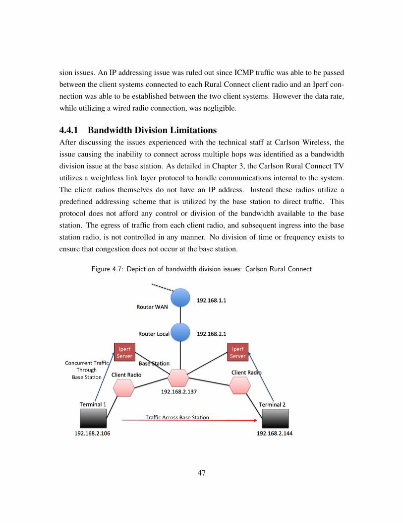
sion issues. An IP addressing issue was ruled out since ICMP traffic was able to be passedbetween the client systems connected to each Rural Connect client radio and an Iperf con-nection was able to be established between the two client systems. However the data rate,while utilizing a wired radio connection, was negligible.
4.4.1 Bandwidth Division LimitationsAfter discussing the issues experienced with the technical staff at Carlson Wireless, theissue causing the inability to connect across multiple hops was identified as a bandwidthdivision issue at the base station. As detailed in Chapter 3, the Carlson Rural Connect TVutilizes a weightless link layer protocol to handle communications internal to the system.The client radios themselves do not have an IP address. Instead these radios utilize apredefined addressing scheme that is utilized by the base station to direct traffic. Thisprotocol does not afford any control or division of the bandwidth available to the basestation. The egress of traffic from each client radio, and subsequent ingress into the basestation radio, is not controlled in any manner. No division of time or frequency exists toensure that congestion does not occur at the base station.
Figure 4.7: Depiction of bandwidth division issues: Carlson Rural Connect
47
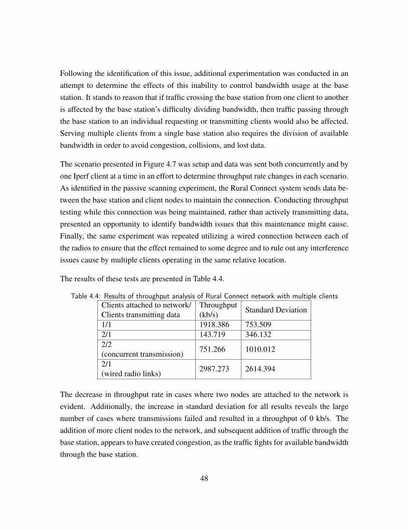
Following the identification of this issue, additional experimentation was conducted in anattempt to determine the effects of this inability to control bandwidth usage at the basestation. It stands to reason that if traffic crossing the base station from one client to anotheris affected by the base station’s difficulty dividing bandwidth, then traffic passing throughthe base station to an individual requesting or transmitting clients would also be affected.Serving multiple clients from a single base station also requires the division of availablebandwidth in order to avoid congestion, collisions, and lost data.
The scenario presented in Figure 4.7 was setup and data was sent both concurrently and byone Iperf client at a time in an effort to determine throughput rate changes in each scenario.As identified in the passive scanning experiment, the Rural Connect system sends data be-tween the base station and client nodes to maintain the connection. Conducting throughputtesting while this connection was being maintained, rather than actively transmitting data,presented an opportunity to identify bandwidth issues that this maintenance might cause.Finally, the same experiment was repeated utilizing a wired connection between each ofthe radios to ensure that the effect remained to some degree and to rule out any interferenceissues cause by multiple clients operating in the same relative location.
The results of these tests are presented in Table 4.4.
Table 4.4: Results of throughput analysis of Rural Connect network with multiple clientsClients attached to network/Clients transmitting data
Throughput(kb/s) Standard Deviation
1/1 1918.386 753.5092/1 143.719 346.1322/2(concurrent transmission) 751.266 1010.012
2/1(wired radio links) 2987.273 2614.394
The decrease in throughput rate in cases where two nodes are attached to the network isevident. Additionally, the increase in standard deviation for all results reveals the largenumber of cases where transmissions failed and resulted in a throughput of 0 kb/s. Theaddition of more client nodes to the network, and subsequent addition of traffic through thebase station, appears to have created congestion, as the traffic fights for available bandwidththrough the base station.
48
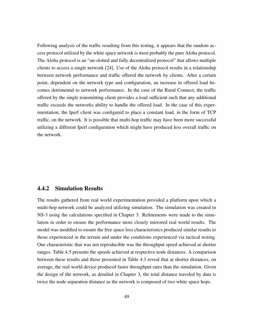
Following analysis of the traffic resulting from this testing, it appears that the random ac-cess protocol utilized by the white space network is most probably the pure Aloha protocol.The Aloha protocol is an “un-slotted and fully decentralized protocol” that allows multipleclients to access a single network [24]. Use of the Aloha protocol results in a relationshipbetween network performance and traffic offered the network by clients. After a certainpoint, dependent on the network type and configuration, an increase in offered load be-comes detrimental to network performance. In the case of the Rural Connect, the trafficoffered by the single transmitting client provides a load sufficient such that any additionaltraffic exceeds the networks ability to handle the offered load. In the case of this exper-imentation, the Iperf client was configured to place a constant load, in the form of TCPtraffic, on the network. It is possible that multi-hop traffic may have been more successfulutilizing a different Iperf configuration which might have produced less overall traffic onthe network.
4.4.2 Simulation Results
The results gathered from real world experimentation provided a platform upon which amulti-hop network could be analyzed utilizing simulation. The simulation was created inNS-3 using the calculations specified in Chapter 3. Refinements were made to the simu-lation in order to ensure the performance more closely mirrored real world results. Themodel was modified to ensure the free space loss characteristics produced similar results tothose experienced in the terrain and under the conditions experienced via tactical testing.One characteristic that was not reproducible was the throughput speed achieved at shorterranges. Table 4.5 presents the speeds achieved at respective node distances. A comparisonbetween these results and those presented in Table 4.3 reveal that at shorter distances, onaverage, the real world device produced faster throughput rates than the simulation. Giventhe design of the network, as detailed in Chapter 3, the total distance traveled by data istwice the node separation distance as the network is composed of two white space hops.
49
Table 4.5: Results of White Space simulation transmitting 2000 kb at varying node distancesNode Distance(meters)
Total Packet TravelDistance(meters)
Time to Complete Transof 2000 kbs (secs)
Throughput(kb/s)
500 1000 2.556 782.468
1000 2000 2.576 776.434
2000 4000 2.614 765.151
3000 6000 2.63 760.592
4000 8000 2.817 709.956
5000 10000 2.859 699.446
5500 11000 2.923 684.113
5800 11600 3.276 610.423
6000 12000 4.325 462.438
6200 12400 15.422 129.682
6500 13000 not completed 0
The simulation does somewhat model the behavior of Rural Connect suite as the nodesreach the outer limits of the distance at which they are able to maintain a connection withthe base station. As the node distance is increased the throughput begins to decrease andthe time to complete the transmission grows significantly. From analysis of the generatedpacket captures, it is apparent that this is due to the loss of several packets and the necessi-tation of numerous retransmissions. Ultimately, throughput becomes negligible across theentire network.
The simulation provides insight into the potential use of Rural Connect suite as a meansof expanding the effective range of communications rapidly. At shorter distances, realworld testing shows that a higher throughput is to be expected, on average. In this case,the throughput through this multi-hop network might increase, assuming the bandwidthdivision shortcomings discussed were handled in order to take advantage of the highersingle-hop throughput. At greater distances the simulation reveals that usable data rates arepossible and a model for the decay of the network as distance increases is presented. Thisdecay closely mirrors the behavior experienced in a single hop network while providinginsight into the behavior of a network utilizing multiple white space network hops.
50
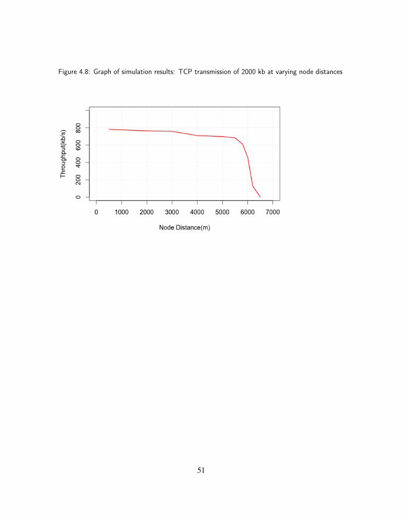
Figure 4.8: Graph of simulation results: TCP transmission of 2000 kb at varying node distances
51

THIS PAGE INTENTIONALLY LEFT BLANK
52
CHAPTER 5:Conclusions
White space technology has the potential to add value to military operations in terms ofspectrum agility and the need for over-the-horizon communications. However, at this point,the technology is not ready or mature enough for deployment in support of military oper-ations. It is likely, given a cooperative development effort by industry entities alreadyinvolved in the development of this technology and government users, that this technologycould be ready for military use in five years.
Given a concerted development effort, future iterations of this technology could have asignificant impact on the means of handling spectrum management in military operations.Currently managing and deconflicting the limited spectral space available for units to utilizein order to establish tactical communications is a significant effort. A great deal of doc-trine is dedicated to process and procedures that facilitate this process [25]. White Spacetechnology presents the possibility of automating a significant amount of this effort at thetactical level, possibly echelons higher, by allowing the spectrum sensing and analyzingabilities of the radios in use to ensure adequate communications links and viable channelswith limited input from users.
Additionally, White Space technology has the potential to be used as a platform to facilitaterapidly expanding networks capable of over-the-horizon communications. White Spacedevices utilize a frequency range capable of propagation through varying terrain and overlong distances, as demonstrated through years of use delivering television signals. Themeans of base station and client communication also lends itself to the construction ofa mesh infrastructure that, if developed, could change the way military communicationsinfrastructures are planned and implemented.
5.1 UsabilityThe device tested, the Carlson Rural Connect, was not designed specifically for use in theenvironment in which it was tested. The system is designed for a planned and static em-placement designed to take maximum advantage of the waveform and adaptive frequency
53
properties of the system. Due to this fact, the system is lacking in many areas related totactical usability when compared to the Harris 7800MP and other radio platforms designedfor tactical use.
The Harris Radio is compact and easily deployed. The means of provisioning power to thesystem only minimally increases its footprint due to a design that includes compartmen-talized storage for batteries which allows for the inclusion into vehicle mounted system.The batteries designed for use with the system provide power for several hours of opera-tion and include chargers that are designed to be used in military vehicles. Though specialantennas are available for use, the system is functional with simple antennas that are easilydeployed and stored, allowing for ease of movement and rapid setup. Programming theradios is difficult in the field and primarily relies on pre-planning of operations to ensurethat network connections are made between radios. Reprogramming on the move requiresadditional steps and is somewhat difficult to adapt to a changing environment, both in termsof frequency use and networked connections.
The Rural Connect is an example of the usability potential of the white space platform andprovides insight into many of the advantages of this technology. Adaptation in terms offrequency use and network planning could potentially leave little for the user to deal withonce deployed. Rather than a significant process to shape a network, adjust a designednetwork plan, or change an operating frequency, the Rural Connect displays the ability ofwhite space technology to potentially allow these tasks to be performed without significantuser intervention. This suite of radios is able to handle identification of the most usablefrequency and adapt to environmental or jamming borne interference while still allowingthe network to be shaped according to the emplacement of nodes. The majority of thecoordinating tasks are handled by the system, or a centrally located control, while the userworries about a few inputs made via an easy to use graphical interface.
While there are usability advantages to this system, there are issues that are primarily aresult of the designed purpose of the system. Unlike the Harris Radio implementation,the Rural Connect lacks design factors that maximize usability in the tactical environment.In order to be useful in this environment, this system requires a dedicated and focuseddevelopment effort. Creating a more rugged platform suited to the elements encountered inaustere conditions is necessary. Additionally, the system must be made more compact. The
54
increased systems and capabilities available in the modern battlefield require an increasingamount of space. Developing this platform so that its advantageous functionality remainswhile ensuring that its form factor fits with the space available for the execution of front-line operations, is essential. Given a concerted development effort, focused on the tailoringof this technology suite towards use in the tactical environment, there is no inherent limitingfactors preventing it from being as useful as currently existing systems. Alternatively, thisfunctionality could be developed for inclusion into communications solutions deployedthroughout the military from developers such as Harris or Persistent Systems.
5.2 PerformanceResearch and analysis conducted to examine the performance characteristics of WhiteSpace technology in general and the Carlson implementation specifically, reveal that thistechnology holds a great deal of promise. Communications in the tactical environment,currently constrained by the limitations of available devices and the congestion of availablespectral space, could benefit a great deal from a device that performs in a similar manner tothe current implementations of White Space technology such as the Carlson Rural ConnectTV.
5.2.1 Distance and ThroughputThroughout testing, the White Space radio displayed the ability to communicate far outsidethe range of the Harris 7800MP radio even while operating at similar frequencies. TheWhite Space radio was able to produce usable throughput at over twice the distance of theHarris radio.
On average, the White Space system produced a higher throughput rate than the Harris ra-dio. This increase in throughput was significant for the majority of iterations and distancesat which tests were conducted. As evident in Figure 4.5, there were virtually no instanceswere the lowest throughput rate experienced on the Rural Connect suite did not exceedthe throughput rate experienced on the Harris radio. This is significant as it displays theability of this technology to effectively utilize a frequency range that is able to propagatethrough terrain and over large distances as well as to make requisite adaptations to the ex-act frequency and modulation utilized in order to produce significant data rate increases ascompared to existing and deployed technology.
55

An issue discovered during testing regarding the throughput performance of the white spaceradio was the throughput fluctuation produced by the suite during the numerous testingiterations. As previously discussed, this fluctuation is most likely caused by changes tothe modulation rate as the radio responds to the spectral environment and the connectionstrength. Development focused on stabilizing this fluctuation would seem to be beneficialto the system. Specifically, for use in military operations, a reliable speed is essential ifdata is to flow over this network in order to connect other systems at a significant range. Ifa network composed of white space hops is to be utilized for the transmission data meant tointegrate other systems, then it is likely that such large fluctuation ranges must be stabilized.The availability of the top end performance range is beneficial to civilian deployments ofWhite Space systems as discussed in Chapter 2, where conditions can be modified, testedand refined in order to achieve maximum benefits. Military operations often do not affordthe ability to ideally refine the environmental conditions the radio will operate in. In thiscase, a more tolerant and stable system will allow other systems to take advantage of stableprovisioned links to transmit essential data and afford predictability to the users of thesystem.
Overall, the promise of white space technology, in terms of propagation distance andthroughput, is apparent. This technology has the ability to advance military capabilitiesand add to the arsenal of capable over-the-horizon communications systems. Before thepotential of this system can be realized the design of the system must be refined with anemphasis on stabilizing performance and producing a system that operates with some levelof predictability under less than ideal conditions.
5.2.2 Bandwidth and Network LimitationsGiven the nature of military operations, the ability to rapidly construct and adjust a networkis essential. A device being utilized as a communications relay in this environment must beflexible and capable of facilitating growth and a mesh, or mesh like, architecture. Essentialto this functionality is the capability of a system to allow data to take multiple hops acrossnodes in order for the transmitted data to reliably arrive at its ultimate destination.
The Carlson Rural Connect does not currently support the ability for multi-hop architec-tures, as evidenced by the results of the numerous tests conducted to examine this capa-
56
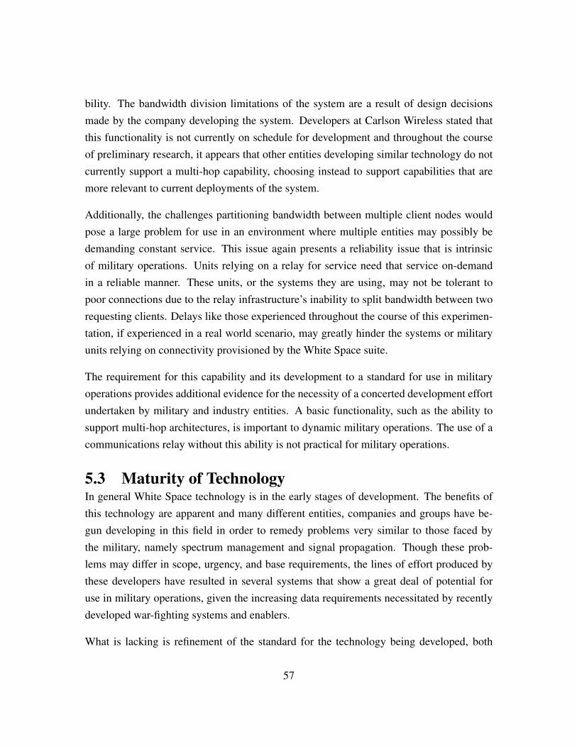
bility. The bandwidth division limitations of the system are a result of design decisionsmade by the company developing the system. Developers at Carlson Wireless stated thatthis functionality is not currently on schedule for development and throughout the courseof preliminary research, it appears that other entities developing similar technology do notcurrently support a multi-hop capability, choosing instead to support capabilities that aremore relevant to current deployments of the system.
Additionally, the challenges partitioning bandwidth between multiple client nodes wouldpose a large problem for use in an environment where multiple entities may possibly bedemanding constant service. This issue again presents a reliability issue that is intrinsicof military operations. Units relying on a relay for service need that service on-demandin a reliable manner. These units, or the systems they are using, may not be tolerant topoor connections due to the relay infrastructure’s inability to split bandwidth between tworequesting clients. Delays like those experienced throughout the course of this experimen-tation, if experienced in a real world scenario, may greatly hinder the systems or militaryunits relying on connectivity provisioned by the White Space suite.
The requirement for this capability and its development to a standard for use in militaryoperations provides additional evidence for the necessity of a concerted development effortundertaken by military and industry entities. A basic functionality, such as the ability tosupport multi-hop architectures, is important to dynamic military operations. The use of acommunications relay without this ability is not practical for military operations.
5.3 Maturity of TechnologyIn general White Space technology is in the early stages of development. The benefits ofthis technology are apparent and many different entities, companies and groups have be-gun developing in this field in order to remedy problems very similar to those faced bythe military, namely spectrum management and signal propagation. Though these prob-lems may differ in scope, urgency, and base requirements, the lines of effort produced bythese developers have resulted in several systems that show a great deal of potential foruse in military operations, given the increasing data requirements necessitated by recentlydeveloped war-fighting systems and enablers.
What is lacking is refinement of the standard for the technology being developed, both
57
in the civilian and military sector. A standard for Wireless Regional Area Networks ex-ists [26], however the immaturity of the technology has not yet allowed for the establish-ment of industry wide standards versus proprietary means of solving problems. More ma-ture technologies, such as Wifi and its different variations rely on a more in-depth standardto dictate the operation of devices. [27] Currently, the existing standards for the operation ofwhite space devices do not facilitate interoperability between the various proprietary solu-tions available. Instead there are many independent efforts, undertaken by several differentcompanies and groups. The short term result of this uncoordinated development effort isequipment that is relatively expensive and difficult to obtain. The acquisition of equipmentfor the purpose of this study was difficult because of its limited availability and its lack ofpresence in any kind of military or government entity. Acquiring it took several monthsand an involved and difficult contracting process.
If this technology, and the benefits it provides, are going to be useful to the civilian andmilitary sectors, a standard must be developed which details the basic operation of thedevices, protocols used for their operation, and capabilities. Currently these devices operatein a very unique and proprietary manner, so any kind of interchangeable functionality isnot possible and no standard services are provisioned. Instead of companies attempting toprovision a defined service in a competitive manner, companies are producing a vision oftheir implementation of White Space technology to an undefined end. A standard set by theindustry will aid in remedying this issue and make this technology more widely availableand more beneficial to users.
Additionally, a cooperative development effort between the military and industry entitieswould be beneficial to produce a device that is capable of operating in environments uniqueto military operations. This research detailed the unique benefits of this technology andtheir relevance to military operations. However, several deficiencies due to non-militarycentric design efforts were also pointed out. The requirements of military use are uniqueand require a focused effort to accurately define and meet these needs.
5.4 ConclusionsWhite Space technology has the potential to enhance the communications capabilities ofpersonnel operating in the tactical environment. This technology provides a means of en-
58
suring that spectrum space is utilized to its maximum potential in an environment whereit might not be possible to deliberately plan its use. This could potentially facilitate theutilization of a seemingly small set of available frequencies by multiple units while notinterfering with resident broadcast and utilization of adjacent frequencies.
White Space technology also makes use of wave forms and frequency ranges which haveproven performance in austere and distant environments. The widespread use of broadcasttelevision and its ability to reach users over a great distance from a broadcast location isevidence that this technology is capable of facilitating over-the-horizon communications.
Though great potential exists, a significant development effort is required if this technol-ogy is to achieve the reliability and performance necessary of systems utilized by militaryorganizations. Given time for this technology to mature and refinement to the frequencysensing, adaptive, and network forming properties of the various implementations of whitespace technology, it is likely that the military will benefit from the inclusion of this tech-nology into the communications systems fielded in the future.
5.5 Recommendations for Future WorkThough the simulation effort performed for this thesis provides some insight into the per-formance of a white space suite over multiple hops, a real world experiment is ideal forgathering data. Additional experimentation should be conducted to determine if differenttesting configurations might produce more favorable results. Configuring the testing plat-form to utilize UDP traffic and conducting an incremented increase off the offered load onthe network might serve to reveal additional data about the networks performance. Ideally,this incremental increase would provide an understanding of the networks true capabilityto handle an offered load from one or multiple clients. A determination of the ability tohandle load may allow for the testing of a multi-hop capability by limiting the offered loadfrom each client attempting to get traffic across the base station node.
The experimentation for this thesis was executed utilizing a limited amount of equipment.Additional Rural Connect equipment, with an emphasis on base station devices, may haveallowed for several more experiments to be executed and increased functionality. Utilizinga larger suite of equipment, additional multi-hop testing should be conducted in an attemptto gather additional data regarding performance. Given access to multiple base station and
59
client units it may be possible to create a node consisting of a hardwired base station andclient, each belonging to a separate white space network, and a shared buffer. The client andbase station node could each write to and read from the shared buffer creating a means toget information from one white space network to another. The construction of this specialnode introduces additional variables into the performance of the network, to include bufferread and write times, but may produce interesting data regarding multi-hop performance.
Following future development to existing white space communications suites, several linesof examination should take place in order to evaluate the preparedness of this technology fordeployment in military operations. The limitations of current implementations preventedthe testing of a large network formed utilizing White Space technology base and clientnodes as a backbone. The examination of a network of this type is vital in determining theusefulness of this technology in the military. Following an examination of this type thistechnology, in the form of suites from various vendors, should be tested in a large scalecommunications exercise such as a Network Integration Exercise.
60
List of References
[1] N. Albert, “Taking advantage of opportunities for commercial satellite communica-tions services,” Defense Business Board, pp. 1–11, Feb. 2013.
[2] Operations, FM 3-0, Headquarters: Department of the Army, 2008, 6.1-6.5.
[3] Tactical Radio Operations, FM 6-02.53, Headquarters: Department of the Army,2009, 4.1 - 4.22.
[4] H. Corp, U.S. Army Brigade Combat Teams to Validate Communications Back-bone Architecture Using Harris Falcon II Wideband Radio Systems During Net-work Integration Evaluation 12.2, 2012. [Online]. Available: http://rf.harris.com/news/view_pressrelease.asp?act=lookup&pr_id=3455
[5] “Mobile ad hoc network with dynamic tdma slot assignments and related methods,”U.S. Patent 5 668 842, Apr. 25, 2013.
[6] J. Dollard, A. Garcia, M. Johnson, W. Llivichuzhaca, and M. Vanwinkle, “Evaluatingdynamic spectrum access on the wireless network after next radio,” M.S. Thesis,Telecommunications Systems Engineering Course, Fort Gordon, GA, 2014.
[7] P. Systems, Technology, 2012. [Online]. Available: http://www.persistentsystems.com/persistent-systems-technology-intro/
[8] P. Systems, Quad Radio Router, 2014. [Online]. Available: http://www.persistentsystems.com/pdf/Quad_SpecSheet.pdf
[9] J. Neuhaus. (2005). Cable TV channel frequencies. [Online]. Available:http://www.jneuhaus.com/fccindex/cablech.html
[10] F. C. Commission. (2007). Digital television. [Online]. Available: http://www.fcc.gov/digital-television
[11] F. C. Commission. (2008). Auction 73 - 700 mhz band. [Online]. Available:http://wireless.fcc.gov/auctions/default.htm?job=auction_factsheet&id=73
[12] C. for White Space Communications University of Strathclyde. (2008). What iswhite space? [Online]. Available: wirelesswhitespace.org
[13] E. Bangeman. (2007). The white space coalition’s plans for fast wireless broadband.[Online]. Available: http://arstechnica.com/gadgets/2007/04/white-space
61
[14] M. Lasar. (2009). Broadcasters sue fcc over white space broadband decision.[Online]. Available: http://arstechnica.com/tech-policy/2009/03/broadcasters-sue-fcc-over-white-space-broadband-decision
[15] Federal Communications Commission, “Unlicensed operation in the TV broadcastbands,” Washington, D.C., Apr. 2012.
[16] M. Research. (2015). Pilots and demonstrations. [Online]. Available: http://research.microsoft.com/en-us/projects/spectrum/pilots.aspx
[17] J. Bolt, “Nation’s first campus ’Super WiFi’ network launches at West VirginiaUniversity,” WVU Today, Nov. 2015.
[18] M. Waddel, S. Thilakwardana, and T. Harold, “Performance of an experimental whitespace base station for mobile and fixed broadband applications,” British BroadcastingCorporation, May 2012.
[19] C. W. Technologies. (2014). Ruralconnect spec sheet - throughput/modulationselection examples. [Online]. Available: http://www.carlsonwireless.com/rural-connect-spec-sheet/
[20] P. Bahl, R. Chandra, T. Moscibroda, R. Murty, and M. Welsh, “White spacenetworking with wi-fi like connectivity,” Microsoft Research/Harvard University,Aug. 2009.
[21] RuralConnect: Modulation Selections, modulation overview, Carlson WirelessTechnologies Inc., 2014.
[22] M. Stoffers and G. Riley, “Comparing the ns-3 propagation models,” White Paper,Georgia Institute of Technology, Mar. 2014.
[23] S. Sanchez, “Modeling a multi-hop architecture using white space devices,” NavalPostgraduate School, Monterey, CA, Tech. Rep., feb 2015.
[24] J. Kurose and K. Ross, Computer Networking: A Top Down Approach. Boston, MA:Pearson Education Inc, 2013, p. 452.
[25] Joint Electromagnetic Spectrum Management Operations, JP 6-01, DC: U.S. JointChiefs of Staff, 2012, I.1 - VI.5.
[26] A. N. Mody and G. Chouinard, IEEE standard for information technology–telecommunications and information exchange between systems–wireless regionalarea networks (WRAN)–specific requirements. policies and procedures for operationin the TV bands. New York: Institute of Electrical and Electronics Engineers, 2011.
62

[27] P. Calhoun, C. S. Inc, M. Montemurro, D. Stanley, R. I. Motion, and A. Networks,“Control and provisioning of wireless access points protocol binding for ieee 802.11,”5 2009, RFC 5416.
63

THIS PAGE INTENTIONALLY LEFT BLANK
64
Initial Distribution List
1. Defense Technical Information CenterFt. Belvoir, Virginia
2. Dudley Knox LibraryNaval Postgraduate SchoolMonterey, California
65