Embed Size (px)
Citation preview
i
NAVAL FACILITIES ENGINEERING SERVICE CENTER Port Hueneme, California 93043-4370
Technical ReportTR-2202-AMP
by
Billy Karrh MAR, Inc.
Peter Tabor
Naval Facilities Engineering Service Center
March 2002
Approved for public release; distribution is unlimited.
DEVELOPMENT OF A BOW MODULE FOR THE SEABOSS CAUSEWAY FERRY
Final Report
Printed on recycled paper

ii
This page left blank.

iii
REPORT DOCUMENTATION PAGE Form Approved
OMB No. 0704-0811 The public reporting burden for this collection of information is estimated to average 1 hour per response, including the time for reviewing instructions, searching existing data sources, gathering and maintaining the data needed, and completing and reviewing the collection of information. Send comments regarding this burden estimate or any other aspect of this collection of information, including suggestions for reducing the burden to Department of Defense, Washington Headquarters Services, Directorate for Information Operations and Reports (0704-0188), 1215 Jefferson Davis Highway, Suite 1204, Arlington, VA 22202-4302. Respondents should be aware that notwithstanding any other provision of law, no person shall be subject to any penalty for failing to comply with a collection of information, it if does not display a currently valid OMB control number.
PLEASE DO NOT RETURN YOUR FORM TO THE ABOVE ADDRESS. 1. REPORT DATE (DD-MM-YYYY) 2. REPORT TYPE 3. DATES COVERED (From – To)
March 2002 Final 4. TITLE AND SUBTITLE 5a. CONTRACT NUMBER
5b. GRANT NUMBER
5c. PROGRAM ELEMENT NUMBER
DEVELOPMENT OF A BOW MODULE FOR THE SEABOSS CAUSEWAY FERRY
6. AUTHOR(S) 5d. PROJECT NUMBER
5e. TASK NUMBER
5f. WORK UNIT NUMBER
Billy Karrh, MAR, Inc. Peter Tabor, NFESC
7. PERFORMING ORGANIZATION NAME(S) AND ADDRESSES 8. PERFORMING ORGANIZATION REPORT NUMBER
Commanding Officer Naval Facilities Engineering Service Center 1100 23rd Avenue Port Hueneme, CA 93043-4370
TR-2202-AMP
9. SPONSORING/MONITORING AGENCY NAME(S) AND ADDRESS(ES) 10. SPONSOR/MONITORS ACRONYM(S)
11. SPONSOR/MONITOR’S REPORT NUMBER(S)
Commander Naval Facilities Engineering Center 1322 Patterson Avenue, Suite 1000 Washington Navy Yard, DC 20374-5065 12. DISTRIBUTION/AVAILABILITY STATEMENT
Approved for public release; distribution is unlimited. 13. SUPPLEMENTARY NOTES
14. ABSTRACT This report describes the development of a bow module for the SEABOSS causeway ferry. A decision was made by the sponsor to develop a bow module that accommodates the majority of beaches where amphibious landings may occur and is practical to operate. This translated to a beach gradient of 1:50 or more. Flatter beach gradients may require a transition from the beach to deeper water by a pier-like facility, such as the floating causeway. The project effort included: a historical review of bow ramps for landing military vehicles on beaches; the development of design criteria for the bow module; the development of alternative concepts for the bow ramp and bow module; the evaluation and selection of a design concept for the bow module; and the preparation of detail design drawings for the bow module.
15. SUBJECT TERMS Causeway ferry, SEABOSS, amphibious landings, floating causeway, beach gradient, bow ramps 16. SECURITY CLASSIFICATION OF: 19a. NAME OF RESPONSIBLE PERSON a. REPORT b. ABSTRACT c. THIS PAGE
17. LIMITATION OF ABSTRACT
18. NUMBER OF PAGES
19b. TELEPHONE NUMBER (include area code) U U U UL 71

iv
This page left blank.
v
EXECUTIVE SUMMARY
The development of a beaching ramp capability for the SEABOSS causeway ferry (CF) bow module is reported. The SEABOSS bow module includes a bow thruster. SEABOSS is an advanced modular, floating causeway system that enables Logistics Over-the-Shore (JLOTS) operations to be executed in open-sea conditions through sea state 3 (SS 3). The SEABOSS beaching ramp is a key component of the self-powered causeway ferry. The primary mission of the SEABOSS CF is to discharge military vehicles from the CF to the beach. This operation is part of the capability to offload vehicular cargo from Military Pre-positioned Force (MPF) ships and Roll-On/Roll-Off (RO/RO) ships.
A historical review of vehicular beaching ramps for various types of vessels was
conducted prior to the development of design concepts. Vehicular beaching ramps for the Navy’s CFs have been used since the original Navy pontoon causeway system was developed during World War II. Beaching ramps for vessels of all types, including ships landing craft, and related applications were examined for both their good and bad features. Current users of the Navy’s causeway system were consulted for their lessons learned from past operations.
Design criteria were developed for the beaching ramp. The beach slope and the draft of the CF are the parameters that have the greatest effect on the design of the beaching ramp. Analytical reviews of the capability of beaching vessels to land on various beach slopes clearly indicated that landing vehicles on beaches flatter than 1:100 slope would require a ramp too long for practical use. Therefore, the SEABOSS Project Management Office opted for a strategy to develop a beach ramp capability for beach slopes of 1:50 or steeper. This ramp would accommodate up to 75 percent of the beach gradients encountered in amphibious landings, as well as provide a ramp that is practical to stow, deploy, and use. Amphibious landing scenarios on flatter beaches will require the use of a transitional capability, such as the floating causeway moored to the beach. The SEABOSS bow module must interface with the landing ramp of the floating causeway. Having established the critical design criteria, concept alternatives were developed for the bow module. Alternatives were for the rake angle, the beach ramp, the deployment/retraction mechanism, and a backup deployment system. The design team judged the alternatives according to a set of evaluation criteria developed for that purpose. Four alternative concepts were selected for final evaluation by the team. The selected concept proposed a hinged ramp with hydraulic ram actuators to deploy and retract the ramp. Hydraulic power to operate the rams is supplied by the diesel engine that drives the bow thruster. With the criteria and design concept established, the design details were executed by NFESC’s design section. A complete set of drawings for the beaching ramp components of the bow module was provided. Detail drawings for the bow module structure and the bow thruster are to be developed by others.

vi
This page left blank.
vii
DEFINITIONS Approach Angle The supplement to the angle between an approach “road” and a sloping ramp. The approach angle refers to the maximum angle that a vehicle can negotiate with its front end as it moves forward onto a sloping ramp. Bow Ramp A hinged ramp structure that enables military vehicles to transition from the deck of the bow module to the beach or other designated floating structures. Breakover Angle Supplement to the angle between two ramps at different slopes. Departure Angle Supplement to the angle between a departure ramp and the departure “road”. The departure angle refers to the maximum angle that a vehicle can negotiate with its rear end as it moves forward off of a sloping ramp. “Dry Ramp” A ramp sufficiently close to the beach to enable military vehicles to reach the shore without the requirement for a fording kit. Generally, no more than 18 inches still water depth at the foot of the ramp is considered a dry ramp. Gap Length Distance from the beach end of the beaching ramp to the waterline on the beach, when the CF is fully grounded for offload. Trafficability Ability to move vehicles over a particular area.
ACRONYMS BM Bow module, a transition module with a floating hull structure and appurtenances, including the bow ramp, that enable the discharge/loading of military vehicles from/to the SEABOSS causeway ferry to the beach or to other designated floating structures. CF Causeway ferry consisting of a powered module, intermediate modules, and a bow module. ELCAS(M) Modular Elevated Causeway FC Floating Causeway HET Heavy Equipment Trailer (US Army)

viii
MCS Modular Causeway System (US Army) MPF Military Pre-positioning Force RRDF Roll-On Roll-Off Discharge Facility RTCH Rough Terrain Container Handler
ix
Table of Contents
Page Chapter 1 INTRODUCTION ...............................................................................................1 Chapter 2 BACKGROUND .................................................................................................3 Chapter 3 HISTORICAL REVIEW OF BEACHING RAMPS ...........................................5
3.1 BEACHING RAMPS FOR STEEP TO MODERATE BEACH GRADIENTS .......................................................................................................5 3.2 BEACHING RAMPS FOR MODERATE TO FLAT BEACH GRADIENTS....5 3.3 LESSONS LEARNED .......................................................................................11 Chapter 4 DESIGN CRITERIA DEVELOPMENT............................................................15 4.1 OPERATIONAL REQUIREMENTS ................................................................15 4.2 PERFORMANCE REQUIREMENTS ..............................................................16 4.3 FUNCTIONAL REQUIREMENTS ..................................................................21 4.4 SEABOSS BOW MODULE CRITERIA ..........................................................22 Chapter 5 CONCEPT ALTERNATIVES ..........................................................................25 5.1 CONCEPTS FOR STEEP TO MODERATE BEACH ......................................25 5.2 CONCEPTS FOR MODERATE TO FLAT BEACH GRADIENTS ................31 Chapter 6 CONCEPT EVALUATION ..............................................................................35 6.1 TRADE-OFF ANALYSES ................................................................................35 6.2 CONCEPT SELECTION ...................................................................................41 Chapter 7 DESIGN EXECUTION .....................................................................................43 Chapter 8 BIBLIOGRAPHY ..............................................................................................47 APPENDIXES A - CAUSEWAY FERRY MOMENTUM BEACHING ANALYSIS ................ A-1 B - TRAFFICABILITY ANALYSIS ....................................................................B-1 C - CONCEPT SELECTION CRITERIA .............................................................C-1 D - NFESC BOW RAMP DESIGN DRAWINGS ............................................... D-1 E - SPECIFICATION FOR SEABOSS CF BOW RAMP MODULE ..................E-1

x
Table of Contents (continued)
Page
List of Figures
Figure 3-1. Beaching ramps for steep to moderate beach gradients, past and present ..............8 Figure 3-2. Transitional or linking capabilities that have been used to assist in the transfer of wheeled cargo on moderate to flat beach gradients ............................10 Figure 3-3 Alternative concepts for moderate to flat beach gradients ....................................12 Figure 4-1 Alternative configurations for the JLMS CF ........................................................18 Figure 4-2 Minimum ramp lengths for “dry” and “wet” ramps for a rigid CF ......................19 Figure 4-3 Minimum ramp lengths for “dry” and “wet” ramps for flexed CF .......................19 Figure 4-4 Effect of flexed CF compared to rigid CF ............................................................20 Figure 4-5 Comparison of hinged and rigid CF on a sand bar ...............................................21 Figure 5-1 Bottom rake and deck taper configuration alternatives for beach ramps ..............26 Figure 5-2 Effect of bottom rake and trim on beaching of CF ...............................................26 Figure 5-3 Beach ramp deployment/retraction alternative concepts ......................................29 Figure 5-4 Beach ramp structure – alternative concepts ........................................................30 Figure 5-5 Beach ramp toe in various deployment modes .....................................................31 Figure 5-6 Alternative concepts for steep- to moderate-beach gradients ...............................31 Figure 6-1 Minimum ramp length as a function of the vertical drop at various ramp slopes............................................................................................36 Figure 6-2 Bow ramp module length and CF connection alternatives ...................................36 Figure 6-3 Rigid and flexed alternative JMLS CF configuration ...........................................37 Figure 6-4 Distance from the beach to the bow of a grounded CF and distance from 18-inch water depth to the bow of a grounded CF for various CF drafts .............38 Figure 6-5 Pilot visibility considerations over beaching ramp ...............................................38 Figure 6-6 JMLS beach ramp backup deployment system .....................................................41 Figure 6-7 Concepts down selected from original alternatives ..............................................42 Figure 6-8 Proposed beaching ramp geometry and general arrangements .............................42 Figure 7-1 Beaching ramp module slope profile on a flat beach ............................................43 Figure 7-2 Vehicle clearance and axle spacing geometry ......................................................44 Figure 7-3 JMLS beaching ramp weight and center of gravity (horizontal) ..........................44 Figure 7-4 JMLS beaching module weight and trim estimate ................................................45
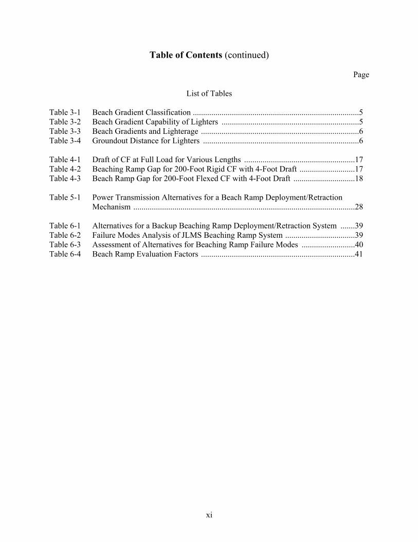
xi
Table of Contents (continued)
Page
List of Tables Table 3-1 Beach Gradient Classification .................................................................................5 Table 3-2 Beach Gradient Capability of Lighters ...................................................................5 Table 3-3 Beach Gradients and Lighterage .............................................................................6 Table 3-4 Groundout Distance for Lighters ............................................................................6 Table 4-1 Draft of CF at Full Load for Various Lengths ......................................................17 Table 4-2 Beaching Ramp Gap for 200-Foot Rigid CF with 4-Foot Draft ...........................17 Table 4-3 Beach Ramp Gap for 200-Foot Flexed CF with 4-Foot Draft ..............................18 Table 5-1 Power Transmission Alternatives for a Beach Ramp Deployment/Retraction Mechanism ............................................................................................................28 Table 6-1 Alternatives for a Backup Beaching Ramp Deployment/Retraction System .......39 Table 6-2 Failure Modes Analysis of JLMS Beaching Ramp System ..................................39 Table 6-3 Assessment of Alternatives for Beaching Ramp Failure Modes ..........................40 Table 6-4 Beach Ramp Evaluation Factors ...........................................................................41

xii
This page left blank.
1
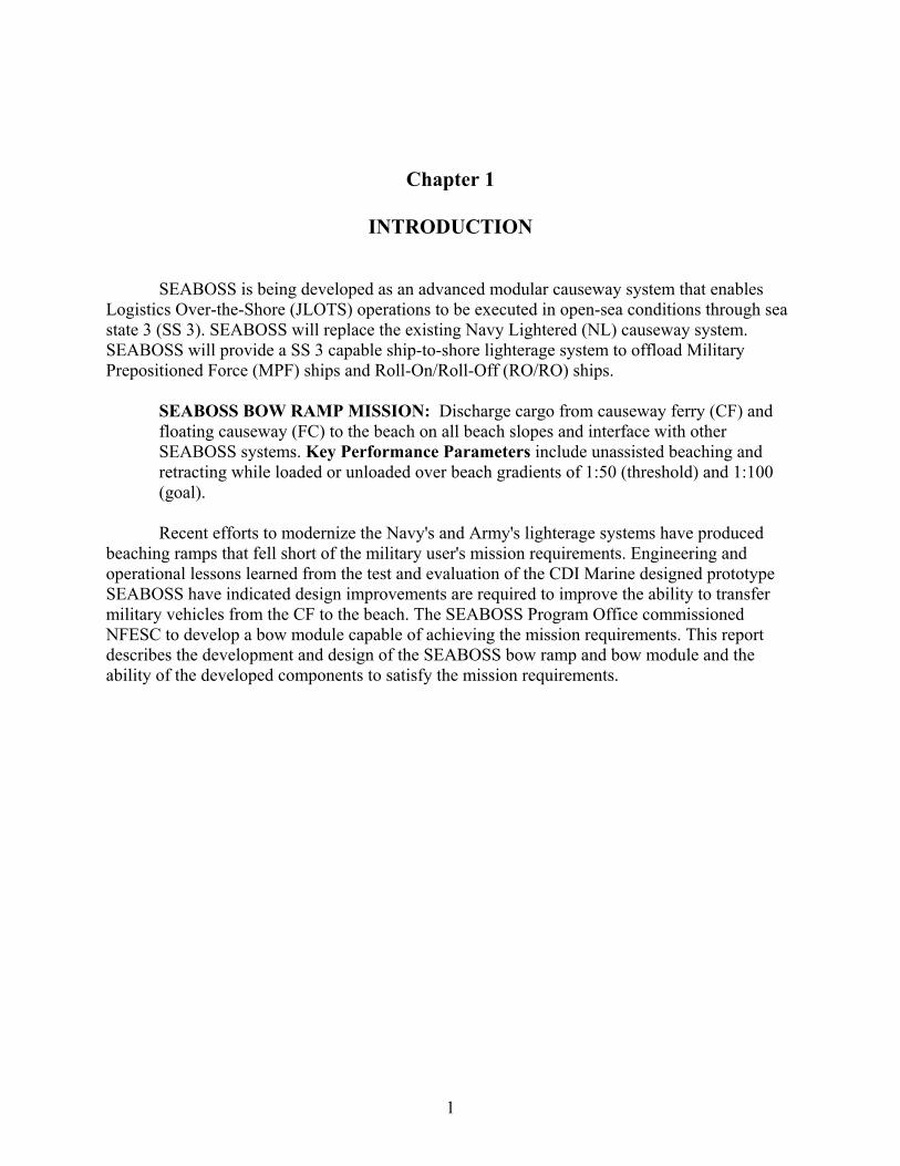
Chapter 1
INTRODUCTION
SEABOSS is being developed as an advanced modular causeway system that enables Logistics Over-the-Shore (JLOTS) operations to be executed in open-sea conditions through sea state 3 (SS 3). SEABOSS will replace the existing Navy Lightered (NL) causeway system. SEABOSS will provide a SS 3 capable ship-to-shore lighterage system to offload Military Prepositioned Force (MPF) ships and Roll-On/Roll-Off (RO/RO) ships.
SEABOSS BOW RAMP MISSION: Discharge cargo from causeway ferry (CF) and floating causeway (FC) to the beach on all beach slopes and interface with other SEABOSS systems. Key Performance Parameters include unassisted beaching and retracting while loaded or unloaded over beach gradients of 1:50 (threshold) and 1:100 (goal).
Recent efforts to modernize the Navy's and Army's lighterage systems have produced
beaching ramps that fell short of the military user's mission requirements. Engineering and operational lessons learned from the test and evaluation of the CDI Marine designed prototype SEABOSS have indicated design improvements are required to improve the ability to transfer military vehicles from the CF to the beach. The SEABOSS Program Office commissioned NFESC to develop a bow module capable of achieving the mission requirements. This report describes the development and design of the SEABOSS bow ramp and bow module and the ability of the developed components to satisfy the mission requirements.

2
This page left blank.
3
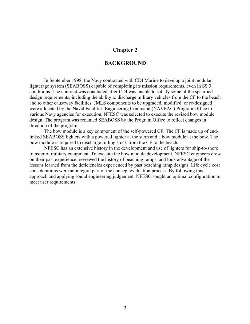
Chapter 2
BACKGROUND
In September 1998, the Navy contracted with CDI Marine to develop a joint modular lighterage system (SEABOSS) capable of completing its mission requirements, even in SS 3 conditions. The contract was concluded after CDI was unable to satisfy some of the specified design requirements, including the ability to discharge military vehicles from the CF to the beach and to other causeway facilities. JMLS components to be upgraded, modified, or re-designed were allocated by the Naval Facilities Engineering Command (NAVFAC) Program Office to various Navy agencies for execution. NFESC was selected to execute the revised bow module design. The program was renamed SEABOSS by the Program Office to reflect changes in direction of the program.
The bow module is a key component of the self-powered CF. The CF is made up of end-linked SEABOSS lighters with a powered lighter at the stern and a bow module at the bow. The bow module is required to discharge rolling stock from the CF to the beach.
NFESC has an extensive history in the development and use of lighters for ship-to-shore transfer of military equipment. To execute the bow module development, NFESC engineers drew on their past experience, reviewed the history of beaching ramps, and took advantage of the lessons learned from the deficiencies experienced by past beaching ramp designs. Life cycle cost considerations were an integral part of the concept evaluation process. By following this approach and applying sound engineering judgement, NFESC sought an optimal configuration to meet user requirements.

4
This page left blank.
5
Chapter 3
HISTORICAL REVIEW OF BEACH RAMPS
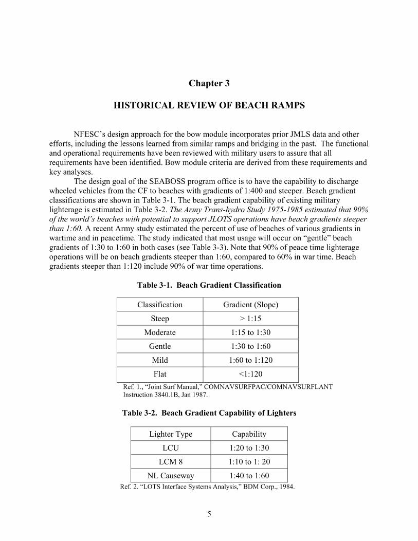
NFESC’s design approach for the bow module incorporates prior JMLS data and other efforts, including the lessons learned from similar ramps and bridging in the past. The functional and operational requirements have been reviewed with military users to assure that all requirements have been identified. Bow module criteria are derived from these requirements and key analyses.
The design goal of the SEABOSS program office is to have the capability to discharge wheeled vehicles from the CF to beaches with gradients of 1:400 and steeper. Beach gradient classifications are shown in Table 3-1. The beach gradient capability of existing military lighterage is estimated in Table 3-2. The Army Trans-hydro Study 1975-1985 estimated that 90% of the world’s beaches with potential to support JLOTS operations have beach gradients steeper than 1:60. A recent Army study estimated the percent of use of beaches of various gradients in wartime and in peacetime. The study indicated that most usage will occur on “gentle” beach gradients of 1:30 to 1:60 in both cases (see Table 3-3). Note that 90% of peace time lighterage operations will be on beach gradients steeper than 1:60, compared to 60% in war time. Beach gradients steeper than 1:120 include 90% of war time operations.
Table 3-1. Beach Gradient Classification
Classification Gradient (Slope)
Steep > 1:15
Moderate 1:15 to 1:30
Gentle 1:30 to 1:60
Mild 1:60 to 1:120
Flat <1:120 Ref. 1., “Joint Surf Manual,” COMNAVSURFPAC/COMNAVSURFLANT Instruction 3840.1B, Jan 1987. Table 3-2. Beach Gradient Capability of Lighters
Lighter Type Capability
LCU 1:20 to 1:30
LCM 8 1:10 to 1: 20
NL Causeway 1:40 to 1:60 Ref. 2. “LOTS Interface Systems Analysis,” BDM Corp., 1984.

6
Table 3-3. Beach Gradients and Lighterage
Beach Gradient War Time Use (%)
Peace Time Use (%)
>1:15 (Steep) --- ---
1:15 to 1:30 (Moderate) 10 20
1:30 to 1:60 (Gentle) 50 70
1:60 to 1:120 (Mild) 30 10
<1:120 (Flat) 10 --- Ref. 3. US Army JMLS Operational Mode Summary/Mission Profile (draft).
In an analysis by MAR, Inc., to determine the capability to install an elevated causeway on a shallow beach gradient, it was determined that many lighters grounded out at considerable distances from the beach. The results of their groundout distance estimates are provided in Table 3-4.
Table 3-4. Groundout Distance for Lighters
Distance from Beach (ft) / Water Depth at Ramp (ft)
Beach Gradient
Lighter Draft (ft) 1:15 1:30 1:60 1:120 1:300
LCU 6.6 100/ dry 200/ 2.6 400/ 4.6 800/ 5.6 2000/ 6.2
LCM 8 4.6 70/ dry 140/ 2 280/ 3.3 550/ 4 1400/ 4.3
NL CWF 4.0 60/ 4 120/ 4 240/ 4 480/ 4 1200/ 4
NL CWF* 4.0 60/ dry 120/ dry 240/ 1 480/ 2.5 1080/ 3.4 **2 bow sections unloaded (1.3 ft draft); remaining 2 sections loaded 100 tons each. * NL CWF = Navy Lightered Causeway Ferry
Ref.4. “ELCAS Installation on Shallow Beach Gradients,” MAR, Inc. TR 960, Aug 1990.
The historical review determined that existing lighters ground out well short of the beach when gradients are flatter than 1:50. SEABOSS criteria specify that the CF draft up to 5 feet for beaching. At 5 feet of draft, the CF will require a substantial ramp length or a transition structure to enable wheeled vehicles to reach the beach. For the CF to get closer to the beach, it can approach the beach at its full speed of approximately 6 knots. Also, the load on the bow section can be arranged such that the bow module is trimmed to approximately the same angle as the beach slope. The precise groundout depth and consequent distance from the beach was computed for a range of beach gradients, and the results are reported later is this report. It was determined during the historical review that a single bow module cannot meet the requirements of all beach gradients. Steeper beaches (greater than 1:50) require a ramp to transition from the 8-foot high CF modules down to the beach. Flatter beaches require some type of transition between where
7
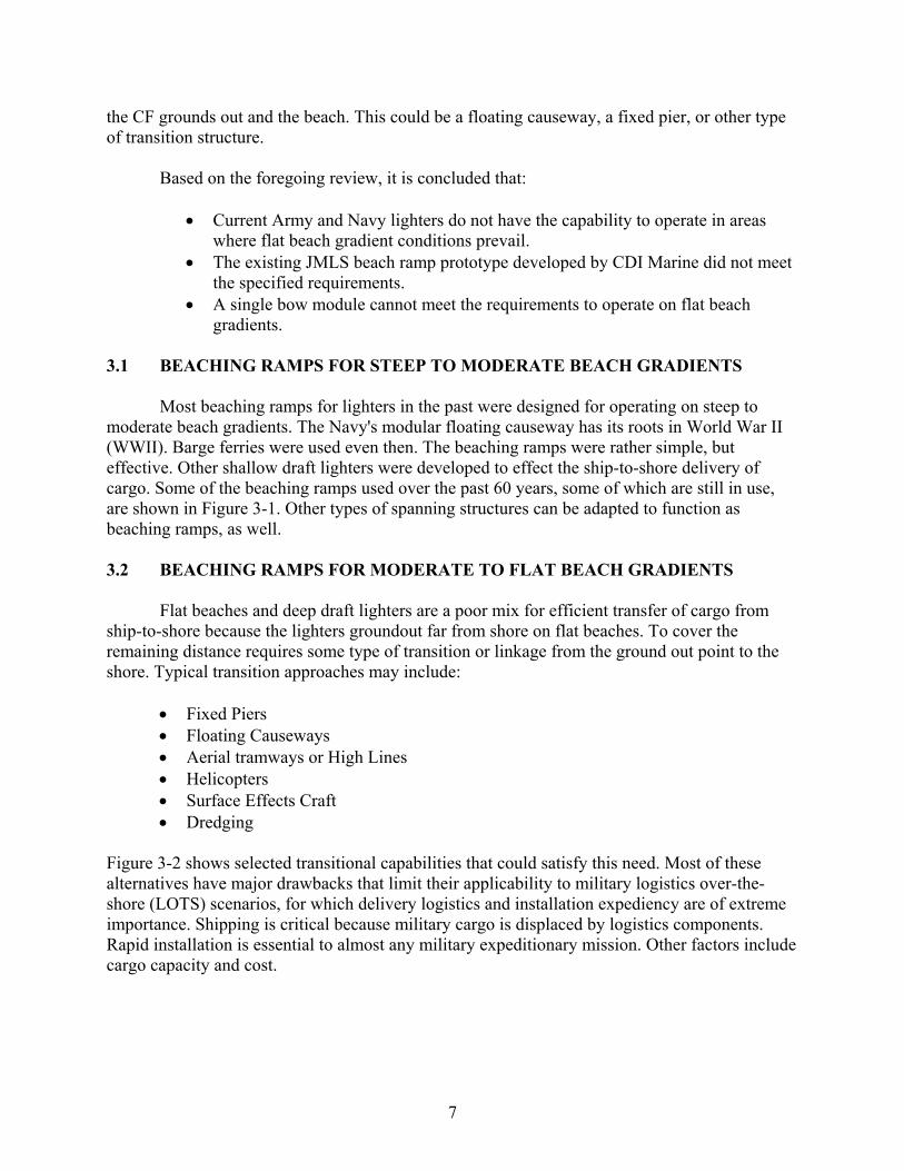
the CF grounds out and the beach. This could be a floating causeway, a fixed pier, or other type of transition structure.
Based on the foregoing review, it is concluded that:
• Current Army and Navy lighters do not have the capability to operate in areas where flat beach gradient conditions prevail.
• The existing JMLS beach ramp prototype developed by CDI Marine did not meet the specified requirements.
• A single bow module cannot meet the requirements to operate on flat beach gradients.
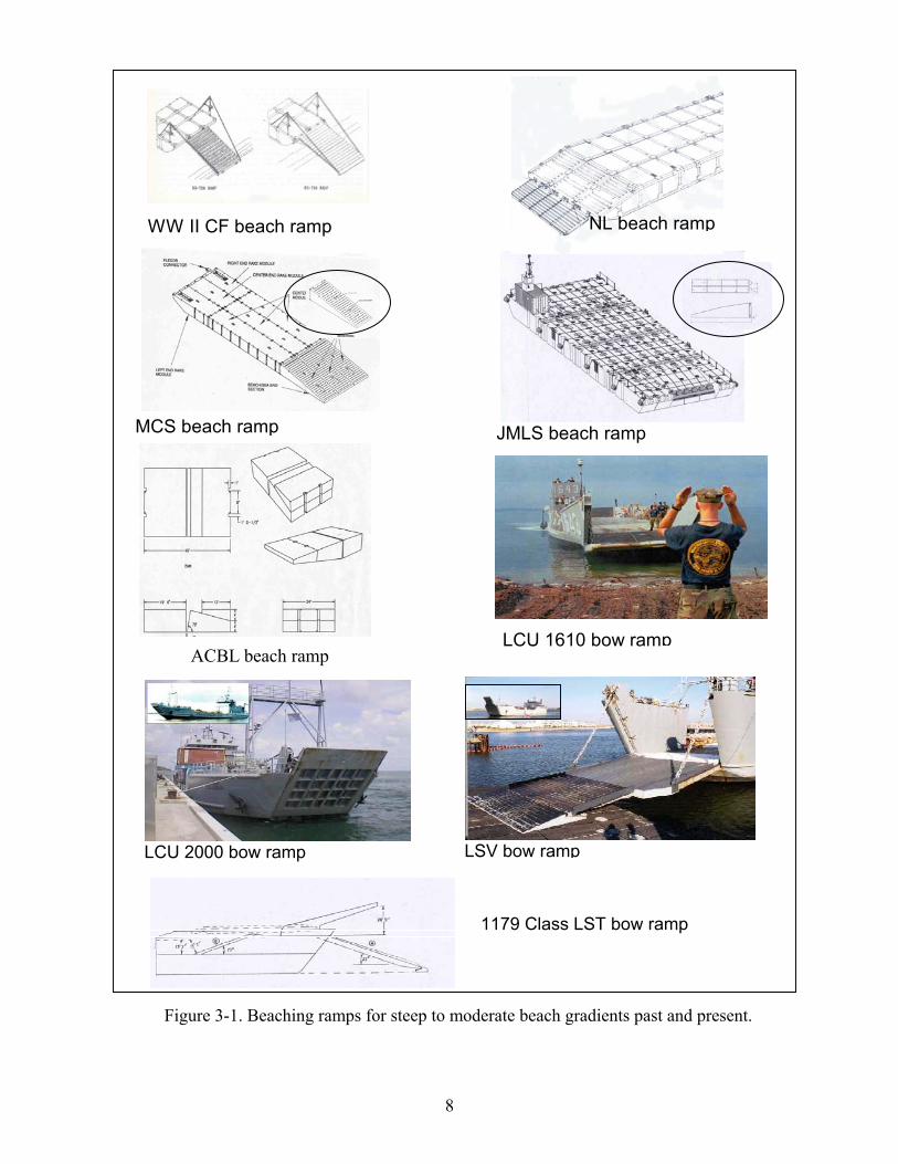
3.1 BEACHING RAMPS FOR STEEP TO MODERATE BEACH GRADIENTS Most beaching ramps for lighters in the past were designed for operating on steep to moderate beach gradients. The Navy's modular floating causeway has its roots in World War II (WWII). Barge ferries were used even then. The beaching ramps were rather simple, but effective. Other shallow draft lighters were developed to effect the ship-to-shore delivery of cargo. Some of the beaching ramps used over the past 60 years, some of which are still in use, are shown in Figure 3-1. Other types of spanning structures can be adapted to function as beaching ramps, as well. 3.2 BEACHING RAMPS FOR MODERATE TO FLAT BEACH GRADIENTS Flat beaches and deep draft lighters are a poor mix for efficient transfer of cargo from ship-to-shore because the lighters groundout far from shore on flat beaches. To cover the remaining distance requires some type of transition or linkage from the ground out point to the shore. Typical transition approaches may include:
• Fixed Piers • Floating Causeways • Aerial tramways or High Lines • Helicopters • Surface Effects Craft • Dredging
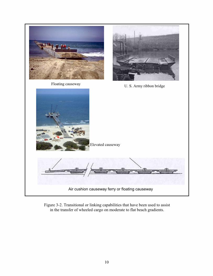
Figure 3-2 shows selected transitional capabilities that could satisfy this need. Most of these alternatives have major drawbacks that limit their applicability to military logistics over-the-shore (LOTS) scenarios, for which delivery logistics and installation expediency are of extreme importance. Shipping is critical because military cargo is displaced by logistics components. Rapid installation is essential to almost any military expeditionary mission. Other factors include cargo capacity and cost.
8
LCU 1610 bow ramp
JMLS beach ramp MCS beach ramp
NL beach ramp WW II CF beach ramp
ACBL beach ramp
LCU 2000 bow ramp
LSV bow ramp
1179 Class LST bow ramp
Figure 3-1. Beaching ramps for steep to moderate beach gradients past and present.
9
RORO ship stern ramp
NATO ACV bow ramp
LCAC bow ramp MEXEFLOTE ramp
NL articulated bow ramp
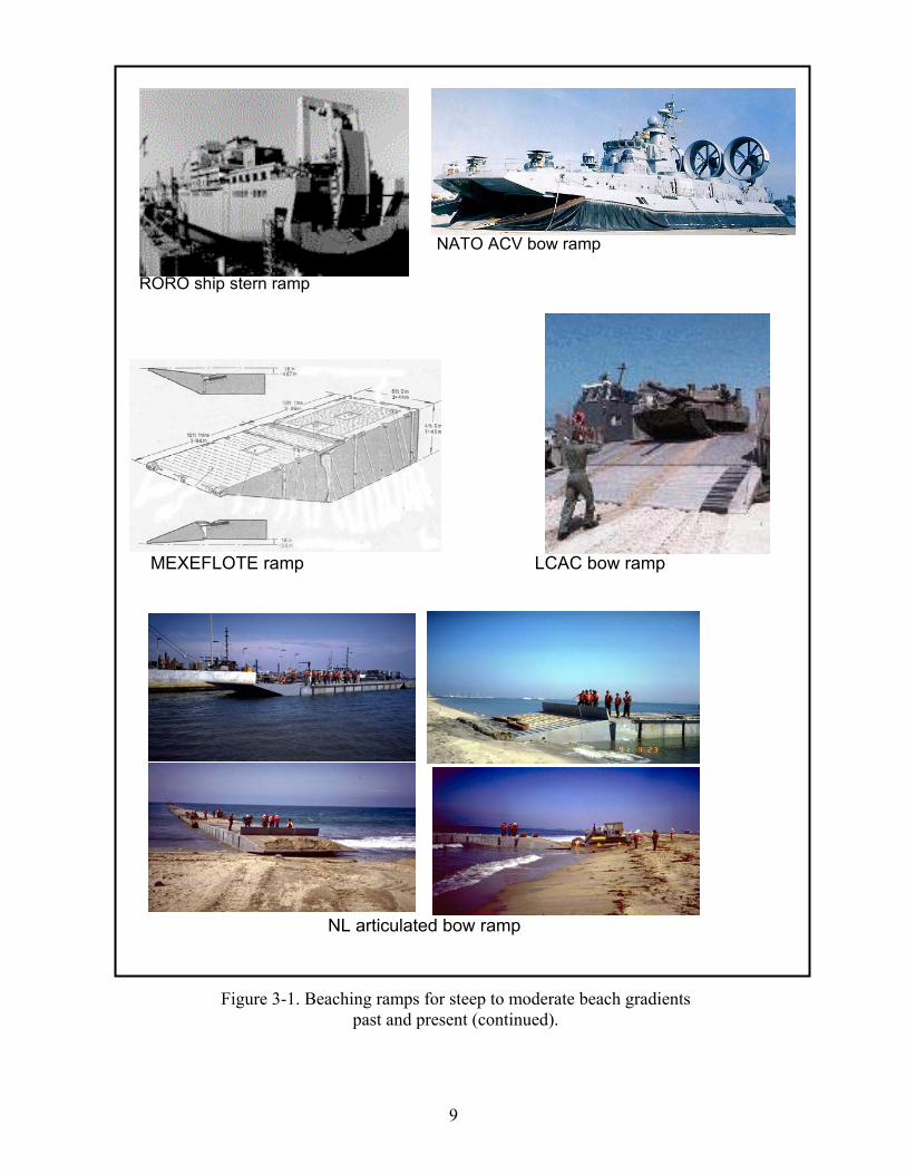
Figure 3-1. Beaching ramps for steep to moderate beach gradients past and present (continued).
10
U. S. Army ribbon bridge Floating causeway
Air cushion causeway ferry or floating causeway
Elevated causeway
Figure 3-2. Transitional or linking capabilities that have been used to assist in the transfer of wheeled cargo on moderate to flat beach gradients.
11
In the past, floating causeways linked end-to-end have been used for short-term applications. Causeways were originally used to provide a link for the WWII Landing Ship Tanks (LSTs), which drafted 6 to 8 feet at the bow. These applications were generally limited to causeway lengths on the order of 1000 to 1500 feet. On very flat beaches (1:400), floating causeways will ground out at 500 to 600 feet from the beach due to drafts of 1.5 to 2 feet, which means vehicles will have to ford the distance to the beach. Often, very flat beaches will have soft muddy bottoms, which would make it difficult for wheeled vehicles to drive from the floating causeway to the beach. Modifying the floating causeways with air cushion skirts has been proposed for this type of scenario to get the causeway beach end onto dry land.
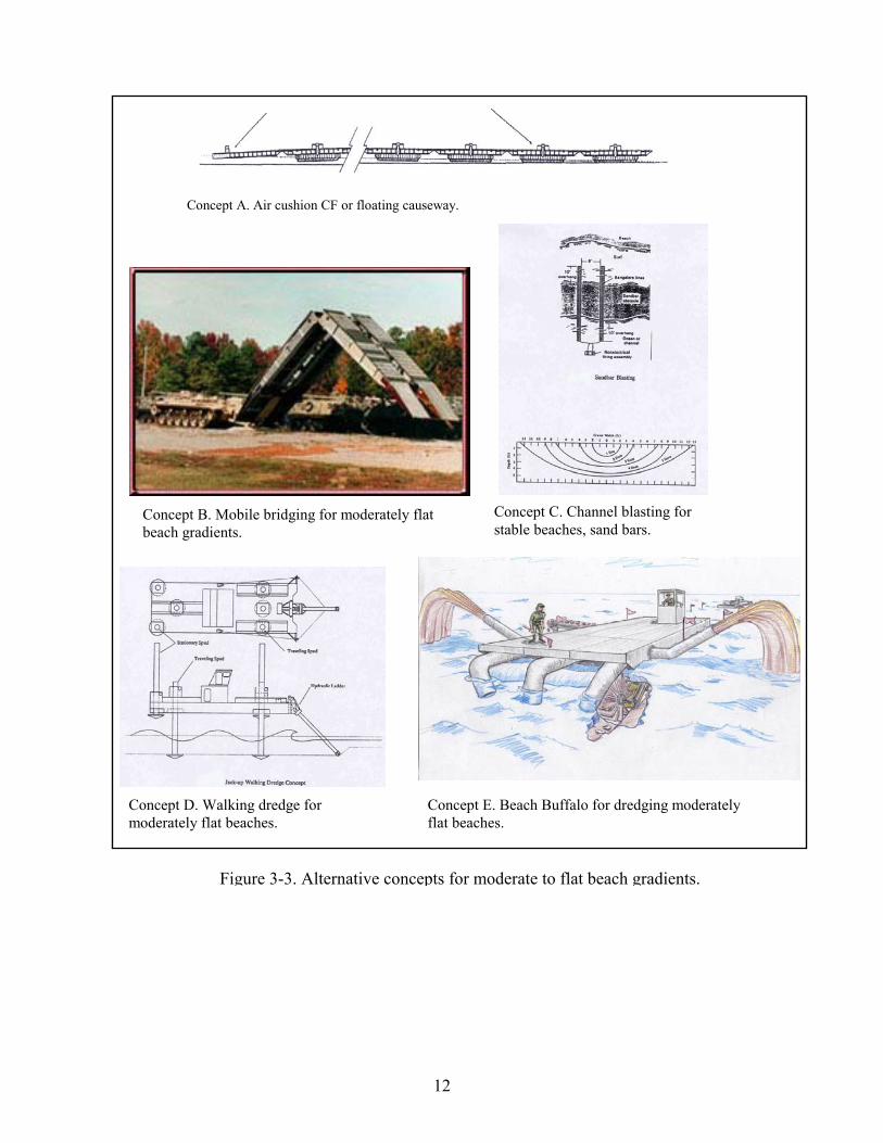
Some additional approaches for intermediate to flat beach gradients are shown in Figure 3-3. Some approaches may solve one type of scenario, but not others. For example, dredging may be a good solution for sand bars, but not for mud bottoms. 3.3 LESSONS LEARNED
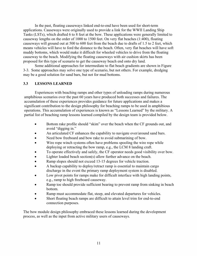
Experiences with beaching ramps and other types of unloading ramps during numerous amphibious scenarios over the past 60 years have produced both successes and failures. The accumulation of these experiences provides guidance for future applications and makes a significant contribution to the design philosophy for beaching ramps to be used in amphibious operations. This accumulation of experiences is known as “Lessons Learned” by the military. A partial list of beaching ramp lessons learned compiled by the design team is provided below.
• Bottom rake profile should “skim” over the beach when the CF grounds out, and avoid “digging in.”
• An articulated CF enhances the capability to navigate over/around sand bars. • Need bow freeboard and bow rake to avoid submarining of bow. • Wire rope winch systems often have problems spooling the wire rope while
deploying or retracting the bow ramp, e.g., the LCM 8 landing craft. • To operate effectively and safely, the CF operator needs good visibility over bow. • Lighter loaded beach section(s) allow further advance on the beach. • Ramp slopes should not exceed 13-15 degrees for vehicle traction. • A backup capability to deploy/retract ramp is essential to maintain cargo
discharge in the event the primary ramp deployment system is disabled. • Low pivot points for ramps make for difficult interface with high landing points,
e.g., ramp to high freeboard causeway. • Ramp toe should provide sufficient bearing to prevent ramp from sinking in beach
bottom. • Ramp must accommodate flat, steep, and elevated departures for vehicles. • Short floating beach ramps are difficult to attain level trim for end-to-end
connection purposes. The bow module design philosophy embraced these lessons learned during the development process, as well as the input from active military users of causeways.
12
Concept B. Mobile bridging for moderately flat beach gradients.
Concept C. Channel blasting for stable beaches, sand bars.
Concept D. Walking dredge for Concept E. Beach Buffalo for dredging moderately moderately flat beaches. flat beaches.
Concept A. Air cushion CF or floating causeway.
Figure 3-3. Alternative concepts for moderate to flat beach gradients.
13
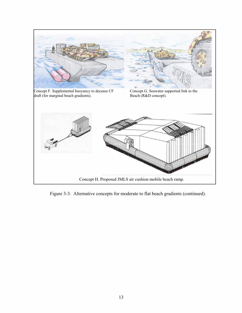
Concept F. Supplemental buoyancy to decease CF Concept G. Seawater supported link to the draft (for marginal beach gradients). Beach (R&D concept).
Concept H. Proposed JMLS air cushion mobile beach ramp.
Figure 3-3. Alternative concepts for moderate to flat beach gradients (continued).

14
This page left blank.

15
Chapter 4
DESIGN CRITERIA DEVELOPMENT
The bow ramp is a component of the bow module (BM), and the BM is a component of the CF. The mission statement and the operational requirements apply to the CF. Operational requirements for the bow ramp and the BM apply insofar as they contribute toward the capability of the CF to complete its mission. The BM and/or the bow ramp cannot achieve the mission alone - only in concert with the other components of the CF.
The design team initially examined and defined the operational, performance, and
functional requirements for a bow ramp to discharge military vehicular cargo from the CF. From those requirements, criteria were developed for the bow ramp:
OPERATIONAL PERFORMANCE FUNCTIONAL REQUIREMENTS REQUIREMENTS REQUIREMENTS
The NFESC design team was assigned responsibility for configuring the module that would house the bow ramp; however, they were not held responsible for the design of the actual module. To acknowledge that distinction, the bow ramp module was called the bow module. In effect, the bow module would be designed around the bow ramp. A specification was developed for the bow ramp and the bow module to assure that the bow module design would be fully compatible with the bow ramp design. After the criteria were established, several analytical tasks were performed to develop the data required for the bow ramp design. Finally, the design was developed on paper. 4.1 OPERATIONAL REQUIREMENTS
The primary operational requirement for the CF is to transfer rolling stock from the roll-
on/roll-off discharge facility (RRDF) to the beach. Operational requirements (OR) are broad statements of the military capability of a given system. In this case, the OR applies to the SEABOSS CF. The bow module is a critical subsystem of the CF that enables the CF to accomplish its mission as defined by the OR. The SEABOSS bow module mission might be stated as:
CRITERIA
16
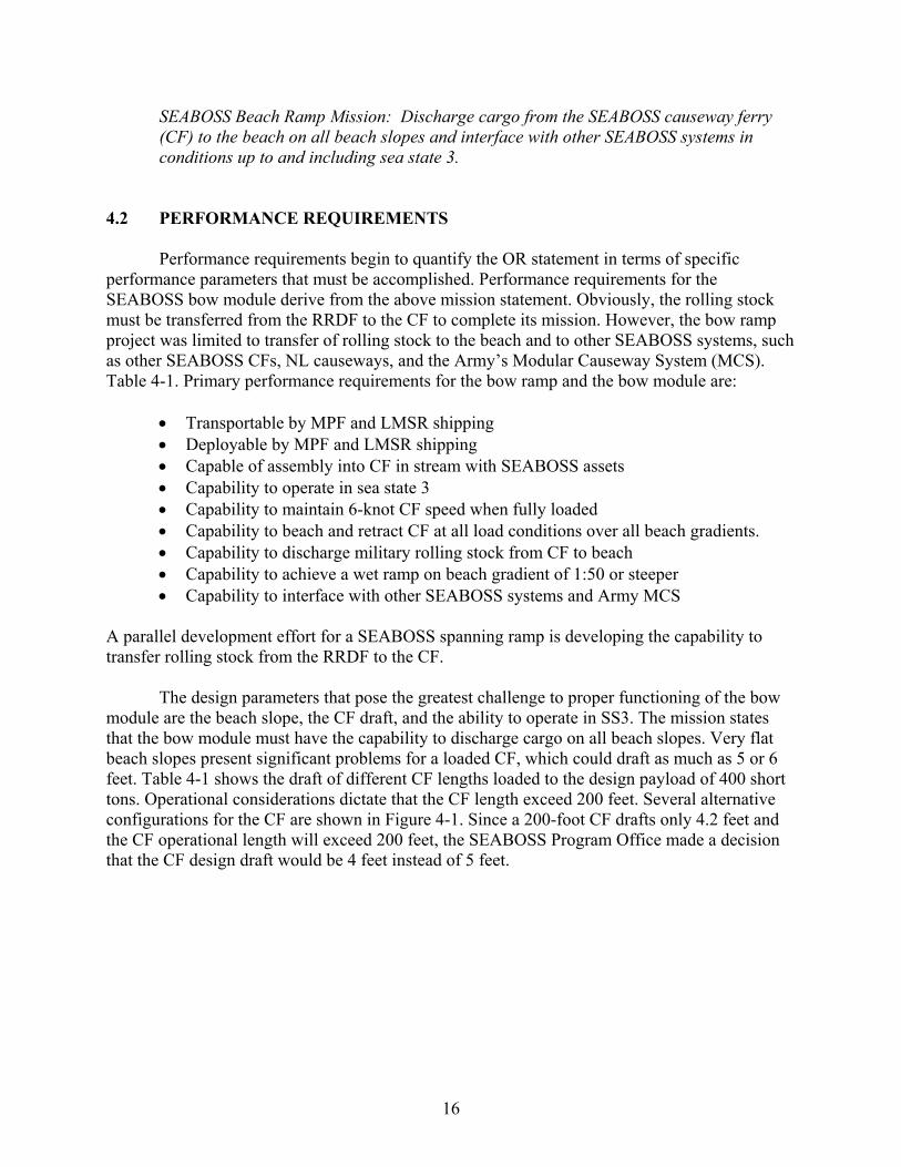
SEABOSS Beach Ramp Mission: Discharge cargo from the SEABOSS causeway ferry (CF) to the beach on all beach slopes and interface with other SEABOSS systems in conditions up to and including sea state 3.
4.2 PERFORMANCE REQUIREMENTS Performance requirements begin to quantify the OR statement in terms of specific
performance parameters that must be accomplished. Performance requirements for the SEABOSS bow module derive from the above mission statement. Obviously, the rolling stock must be transferred from the RRDF to the CF to complete its mission. However, the bow ramp project was limited to transfer of rolling stock to the beach and to other SEABOSS systems, such as other SEABOSS CFs, NL causeways, and the Army’s Modular Causeway System (MCS). Table 4-1. Primary performance requirements for the bow ramp and the bow module are:
• Transportable by MPF and LMSR shipping • Deployable by MPF and LMSR shipping • Capable of assembly into CF in stream with SEABOSS assets • Capability to operate in sea state 3 • Capability to maintain 6-knot CF speed when fully loaded • Capability to beach and retract CF at all load conditions over all beach gradients. • Capability to discharge military rolling stock from CF to beach • Capability to achieve a wet ramp on beach gradient of 1:50 or steeper • Capability to interface with other SEABOSS systems and Army MCS
A parallel development effort for a SEABOSS spanning ramp is developing the capability to transfer rolling stock from the RRDF to the CF. The design parameters that pose the greatest challenge to proper functioning of the bow module are the beach slope, the CF draft, and the ability to operate in SS3. The mission states that the bow module must have the capability to discharge cargo on all beach slopes. Very flat beach slopes present significant problems for a loaded CF, which could draft as much as 5 or 6 feet. Table 4-1 shows the draft of different CF lengths loaded to the design payload of 400 short tons. Operational considerations dictate that the CF length exceed 200 feet. Several alternative configurations for the CF are shown in Figure 4-1. Since a 200-foot CF drafts only 4.2 feet and the CF operational length will exceed 200 feet, the SEABOSS Program Office made a decision that the CF design draft would be 4 feet instead of 5 feet.
17
Table 4-1. Draft of CF at Full Load for Various Lengths
Load (short ton)
CF Length (ft)
Draft (ft)
LIGHT ANY ~1.6 400 200 ~4.2 400 260 ~3.6 400 340 ~3.2
(SEABOSS CF Payload Requirement = 400 short tons)
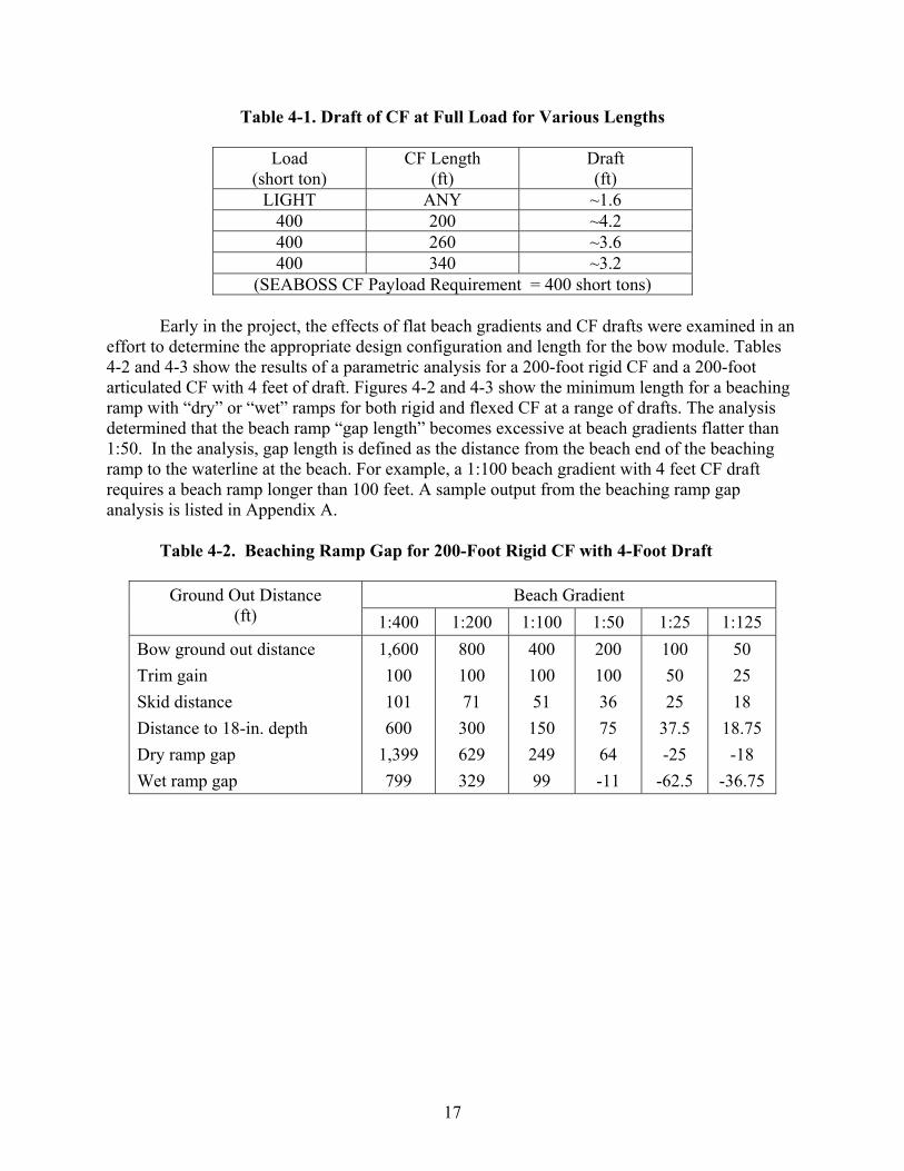
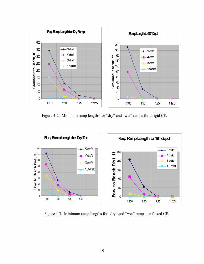
Early in the project, the effects of flat beach gradients and CF drafts were examined in an effort to determine the appropriate design configuration and length for the bow module. Tables 4-2 and 4-3 show the results of a parametric analysis for a 200-foot rigid CF and a 200-foot articulated CF with 4 feet of draft. Figures 4-2 and 4-3 show the minimum length for a beaching ramp with “dry” or “wet” ramps for both rigid and flexed CF at a range of drafts. The analysis determined that the beach ramp “gap length” becomes excessive at beach gradients flatter than 1:50. In the analysis, gap length is defined as the distance from the beach end of the beaching ramp to the waterline at the beach. For example, a 1:100 beach gradient with 4 feet CF draft requires a beach ramp longer than 100 feet. A sample output from the beaching ramp gap analysis is listed in Appendix A.
Table 4-2. Beaching Ramp Gap for 200-Foot Rigid CF with 4-Foot Draft
Beach Gradient Ground Out Distance (ft) 1:400 1:200 1:100 1:50 1:25 1:125
Bow ground out distance Trim gain Skid distance Distance to 18-in. depth Dry ramp gap Wet ramp gap
1,600 100 101 600
1,399 799
800 100 71 300 629 329
400 100 51 150 249 99
200 100 36 75 64 -11
100 50 25
37.5 -25
-62.5
50 25 18
18.75 -18
-36.75
18
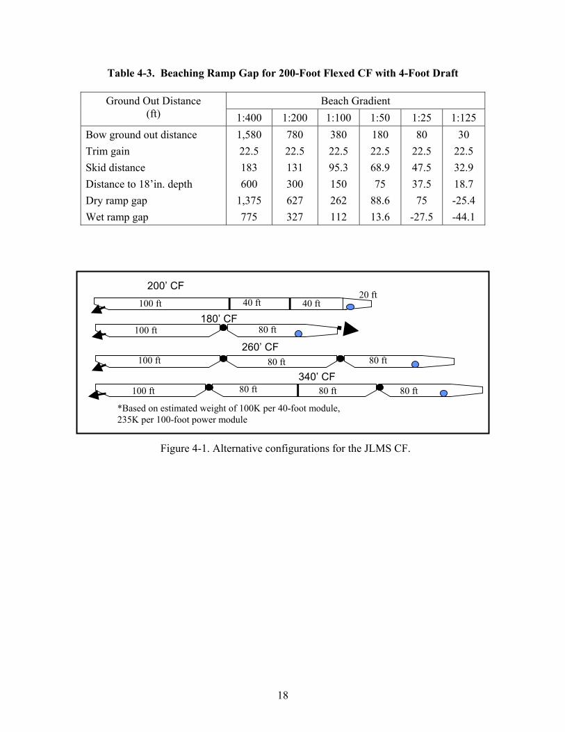
Table 4-3. Beaching Ramp Gap for 200-Foot Flexed CF with 4-Foot Draft
Beach Gradient Ground Out Distance (ft) 1:400 1:200 1:100 1:50 1:25 1:125
Bow ground out distance Trim gain Skid distance Distance to 18’in. depth Dry ramp gap Wet ramp gap
1,580 22.5 183 600
1,375 775
780 22.5 131 300 627 327
380 22.5 95.3 150 262 112
180 22.5 68.9 75
88.6 13.6
80 22.5 47.5 37.5 75
-27.5
30 22.5 32.9 18.7 -25.4 -44.1
*Based on estimated weight of 100K per 40-foot module, 235K per 100-foot power module
100 ft 80 ft 80 ft 80 ft 340’ CF
100 ft 80 ft 80 ft 260’ CF
100 ft 40 ft 40 ft 20 ft
200’ CF
100 ft 80 ft 180’ CF
Figure 4-1. Alternative configurations for the JLMS CF.
19
Ramp Length to 18" Depth
020406080
100120140160180200
1:100 1:50 1:25 1:12.5
Gro
undo
ut to
18"
, ft
5' draft
4' draft
3' draft
1.5' draft
Req. Ramp Length for Dry Ramp
0
50
100
150
200
250
300
350
400
1:100 1:50 1:25 1:12.5
Gro
undo
ut to
Bea
ch, f
t
5' draft
4' draft
3' draft
1.5' draft
Figure 4-2. Minimum ramp lengths for “dry” and “wet” ramps for a rigid CF.
Req. Ramp Length to 18" depth
0
50
100
150
200
250
1:100 1:50 1:25 1:12.5
Bow
to B
each
Dis
t, ft
5' draft
4' draft
3' draft
1.5' draf t
Req. Ramp Length for Dry Toe
0
50
100
150
200
250
300
350
400
1:100 1:50 1:25 1:12.5
Bow
to B
each
Dis
t, ft
5' draft
4' draft
3' draft
1.5' draft
Figure 4-3. Minimum ramp lengths for “dry” and “wet” ramps for flexed CF.
20
Although a 100-foot-plus ramp can be developed, such a ramp length would greatly diminish the ramp's operational utility. The Army's study results of Table 3-3 indicate that 60% of the war time applications occurred on beach gradients steeper than 1:60, while 30% occurred on gradients between 1:60 and 1:120. In addition, weight and cube of a 100-foot plus ramp will impact on the transport logistics and SEABOSS CF assembly at sea. Based on these considerations, the SEABOSS Program Office elected a strategy to develop a beach ramp capability for beach gradients steeper than 1:50. For beach gradients between 1:50 and 1:200, adjunct hardware such as floating causeways would be required.
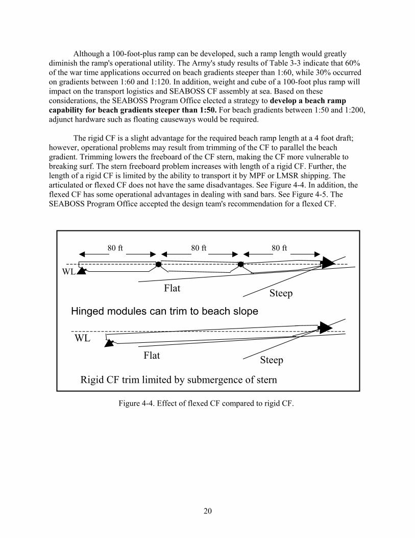
The rigid CF is a slight advantage for the required beach ramp length at a 4 foot draft; however, operational problems may result from trimming of the CF to parallel the beach gradient. Trimming lowers the freeboard of the CF stern, making the CF more vulnerable to breaking surf. The stern freeboard problem increases with length of a rigid CF. Further, the length of a rigid CF is limited by the ability to transport it by MPF or LMSR shipping. The articulated or flexed CF does not have the same disadvantages. See Figure 4-4. In addition, the flexed CF has some operational advantages in dealing with sand bars. See Figure 4-5. The SEABOSS Program Office accepted the design team's recommendation for a flexed CF.
Flat Steep
80 ft 80 ft 80 ft
WL
Flat Steep
WL
Hinged modules can trim to beach slope
Rigid CF trim limited by submergence of stern
Figure 4-4. Effect of flexed CF compared to rigid CF.

21
4.3 FUNCTIONAL REQUIREMENTS
Functional requirements take the performance requirements to the next level, as the system concept begins to take shape. Again, many of the functional requirements for the bow ramp subsystem enable the CF to accomplish its missions.
Operational requirements determine what missions the beach ramp system must accomplish. Functional and performance requirements evolve from these operational requirements and the hardware chosen to meet the operational requirements.
The beach gradient has a profound influence on the length requirements for a bow ramp. For example, steep beach gradients with a CF full-load draft of 4 feet require just a step down ramp from the 8-foot high deck. The step-down ramp with a slope limit of 7 degrees is long enough to reach a water depth considered to be a “dry ramp” for vehicular traffic. For the beach ramp, a dry ramp is defined as the maximum water depth at which applicable military vehicles can operate without a fording kit. At the other extreme, flat beach gradients with a CF full-load draft of 4 feet require a step-down ramp and a transition capability from the CF grounding water depth to a water depth considered to be a dry ramp.
From the beaching gap analysis, it was determined that a 1:50 beach slope requires a bow ramp length that closely matches the length required for a step-down ramp capability from an 8-foot high module. It should be noted that a significant majority of beach landings in war time have been on beach gradients steeper than 1:50. These data led the SEABOSS Program Office to opt for developing a primary bow module capability to operate on steep to moderate beaches. For beaches flatter than 1:50, CF to beach links or transitional capabilities will be required.
W
WSAND
SAND
Hinged modules apply less load on sand bar friction resistance
• Rigid CF can become grounded on sand bar and have to await high tide. • Stern of CF likely to be awash from surf as bow rides up sand bar
Figure 4-5. Comparison of hinged and rigid CF on a sand bar.
22
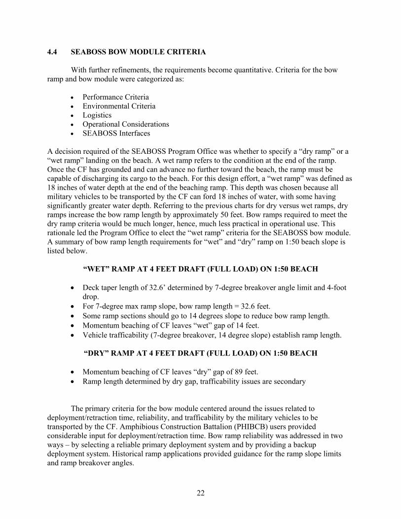
4.4 SEABOSS BOW MODULE CRITERIA
With further refinements, the requirements become quantitative. Criteria for the bow ramp and bow module were categorized as:
• Performance Criteria • Environmental Criteria • Logistics • Operational Considerations • SEABOSS Interfaces
A decision required of the SEABOSS Program Office was whether to specify a “dry ramp” or a “wet ramp” landing on the beach. A wet ramp refers to the condition at the end of the ramp. Once the CF has grounded and can advance no further toward the beach, the ramp must be capable of discharging its cargo to the beach. For this design effort, a “wet ramp” was defined as 18 inches of water depth at the end of the beaching ramp. This depth was chosen because all military vehicles to be transported by the CF can ford 18 inches of water, with some having significantly greater water depth. Referring to the previous charts for dry versus wet ramps, dry ramps increase the bow ramp length by approximately 50 feet. Bow ramps required to meet the dry ramp criteria would be much longer, hence, much less practical in operational use. This rationale led the Program Office to elect the “wet ramp” criteria for the SEABOSS bow module. A summary of bow ramp length requirements for “wet” and “dry” ramp on 1:50 beach slope is listed below.
“WET” RAMP AT 4 FEET DRAFT (FULL LOAD) ON 1:50 BEACH
• Deck taper length of 32.6’ determined by 7-degree breakover angle limit and 4-foot drop.
• For 7-degree max ramp slope, bow ramp length = 32.6 feet. • Some ramp sections should go to 14 degrees slope to reduce bow ramp length. • Momentum beaching of CF leaves “wet” gap of 14 feet. • Vehicle trafficability (7-degree breakover, 14 degree slope) establish ramp length.
“DRY” RAMP AT 4 FEET DRAFT (FULL LOAD) ON 1:50 BEACH
• Momentum beaching of CF leaves “dry” gap of 89 feet. • Ramp length determined by dry gap, trafficability issues are secondary
The primary criteria for the bow module centered around the issues related to deployment/retraction time, reliability, and trafficability by the military vehicles to be transported by the CF. Amphibious Construction Battalion (PHIBCB) users provided considerable input for deployment/retraction time. Bow ramp reliability was addressed in two ways – by selecting a reliable primary deployment system and by providing a backup deployment system. Historical ramp applications provided guidance for the ramp slope limits and ramp breakover angles.

23
The function and performance of the bow ramp cannot be divorced from the bow module, which houses and supports the ramp and provides one half of the 8-foot step down from the CF deck. Consequently, performance specifications for the bow ramp were combined with those of the bow module, even though the SEABOSS bow ramp project included a detailed design for the bow ramp, but not for the bow module.

24
This page left blank.
25
Chapter 5
CONCEPT ALTERNATIVES
Early in the project, the SEABOSS Program Office agreed that the capability to discharge cargo from a CF to the beach on all beach slopes was not practical within the SEABOSS deployment concept. Beach slopes of 1:50 or steeper were selected for the basic SEABOSS CF bow module, based on NFESC generated data. The data indicated that the bow ramp for steeper beaches could be kept to a reasonable length and maintain the SEABOSS logistics concept. Flatter beach slopes would require a shore link from the beach to the water depth where the CF grounds out. Floating pontoon causeways have performed this function for LST and deeper draft lighters in the past. Alternatives to be explored for moderate to flat beaches will be of this type. 5.1 CONCEPTS FOR STEEP TO MODERATE BEACH
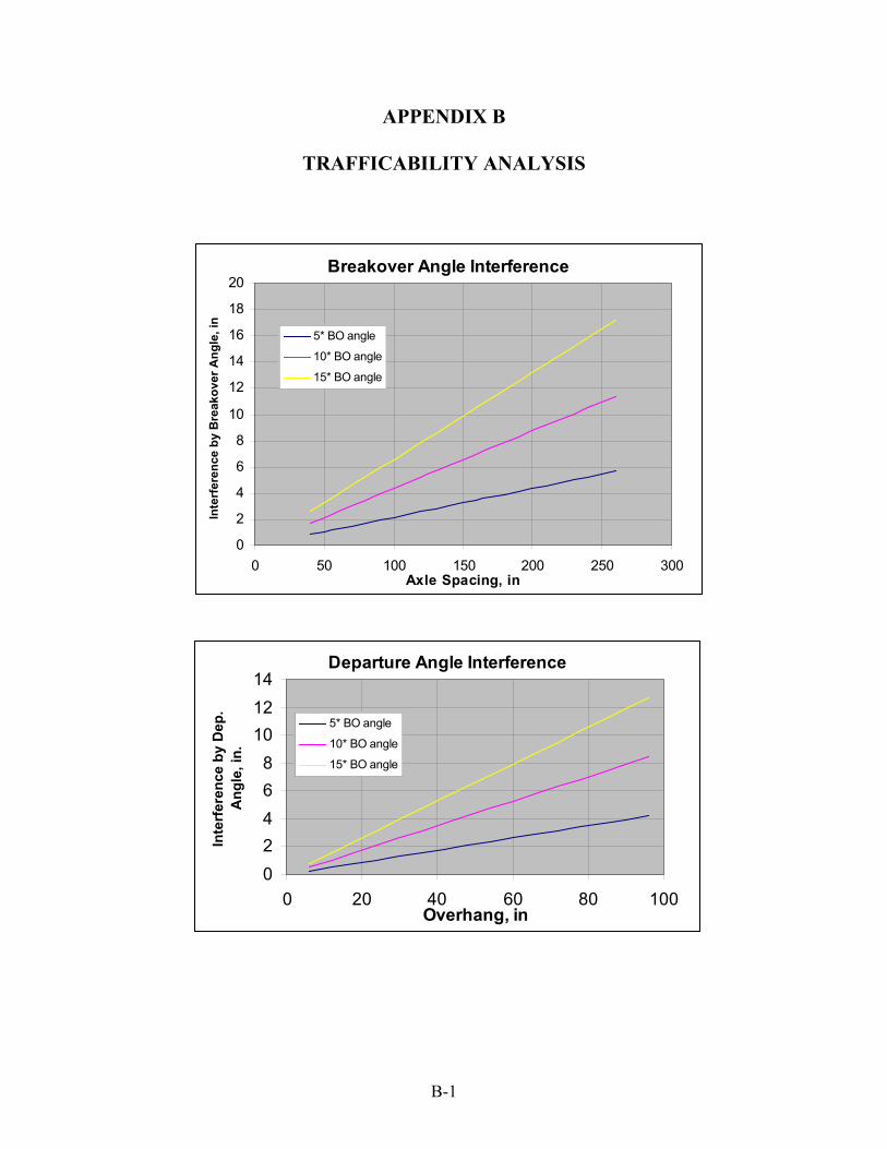
Brainstorming sessions generated bow ramp concepts and concept approaches. It was apparent that the bow ramp could not be separated from the module that housed and supported the ramp. To that end, deck taper was used to bring the module deck height down from 8 feet to 4 feet. A built-in deck taper reduces the “active,” (deployed) length of the bow ramp. The bow ramp length begins at the end of the deck taper and effects the remaining 4-foot drop to the beach. Deck taper and ramp slopes are limited by the requirement for trafficability by a wide range of military vehicles. An analysis of the trafficability of ramp breakover angles and ramp departure angles is provided in Appendix B. The Rough Terrain Container Handler (RTCH) is one of the design drivers for structural design of the bow module.
The concept selection/evaluation process explored several functional elements or subsystems of the bow ramp and bow module. Alternatives for these subsystems were conceived and evaluated as part of the overall beach ramp/module system. The subsystems included:
• Bottom Rake Configuration • Deck Taper Configuration • Beach Ramp Deployment/Retraction • Beach Ramp Power • Beach Ramp Toe
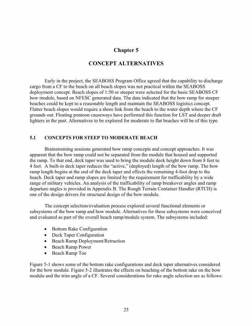
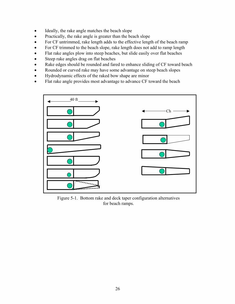
Figure 5-1 shows some of the bottom rake configurations and deck taper alternatives considered for the bow module. Figure 5-2 illustrates the effects on beaching of the bottom rake on the bow module and the trim angle of a CF. Several considerations for rake angle selection are as follows:
26
• Ideally, the rake angle matches the beach slope • Practically, the rake angle is greater than the beach slope • For CF untrimmed, rake length adds to the effective length of the beach ramp • For CF trimmed to the beach slope, rake length does not add to ramp length • Flat rake angles plow into steep beaches, but slide easily over flat beaches • Steep rake angles drag on flat beaches • Rake edges should be rounded and fared to enhance sliding of CF toward beach • Rounded or curved rake may have some advantage on steep beach slopes • Hydrodynamic effects of the raked bow shape are minor • Flat rake angle provides most advantage to advance CF toward the beach
40 ft
Ch
Figure 5-1. Bottom rake and deck taper configuration alternatives
for beach ramps.
27
The types of deployment/retraction alternatives considered for the bow ramp are:
Deployment/Retraction Alternatives • Winch and Wire Rope • Windlass and Chain • Hydraulic Cylinders • Worm or Screw Drive • Block and Tackle Rigging • Various Mechanical Linkages
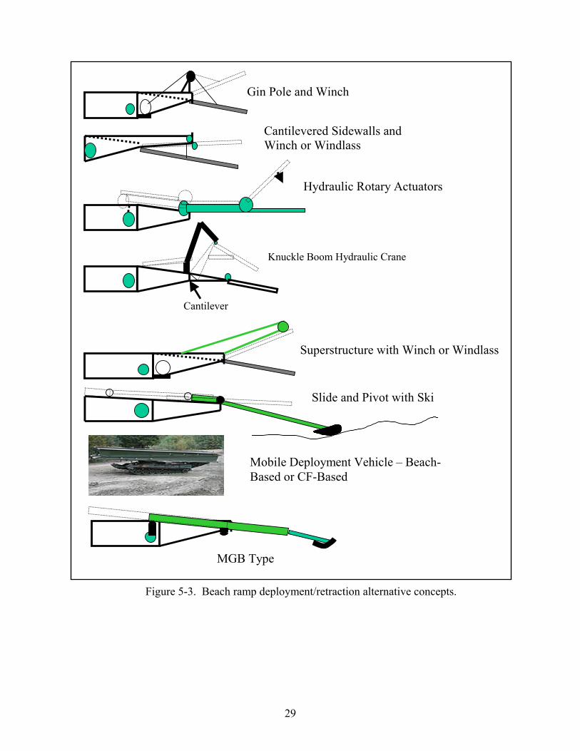
Figure 5-3 illustrates several deployment/retraction alternative concepts for the bow ramp. Table 5-1 shows some of the power transmission choices considered for the bow ramps. Some of the deployment/retraction alternative selection factors are
• Estimated force to deploy/retract ramp is high (estimated 30,000 pounds). • Some safety issues with winch and windlass systems have been experienced. • Travel distance to deploy/retract the ramp is in the order of 3 to 6 feet. • A mechanism like hydraulic cylinders or worm drives seems appropriate. • Distance from prime mover at bow thruster to beach ramp discourages mechanical
linkages. • Hydraulics, pneumatics, or electrical power transmission favored.
TO 200 feet
~20 feet
50 feet
NO TRIM, SQUARE BOW
FLEXED MODULES WITH END MODULE TRIM
NO TRIM, RAKED BOW
FULL TRIM, SQUARE BOW
100 feet
Figure 5-2. Effect of bottom rake and trim on beaching of CF.

28
• Electrical application not suited for the amphibious environment and PHIBCBs are not accustomed to this type of electrical component.
• Pneumatic cylinders would get too large for the high loads required. Also, pneumatic devices have potential for “explosive” failures.
• Hydraulic cylinders left as leading choice. Environmentally safe hydraulic oils are available.
Table 5-1. Power Transmission Alternatives for a Beach Ramp Deployment/Retraction Mechanism
Power Transmission
Mechanism Hydraulic Electrical Pneumatic Mechanical
Winch and Wire Rope X X X X Windlass and Chain X X X X Hydraulic Cylinders X Pneumatic Cylinders X Screw or Worm Drive X X X X Mechanical Linkage X
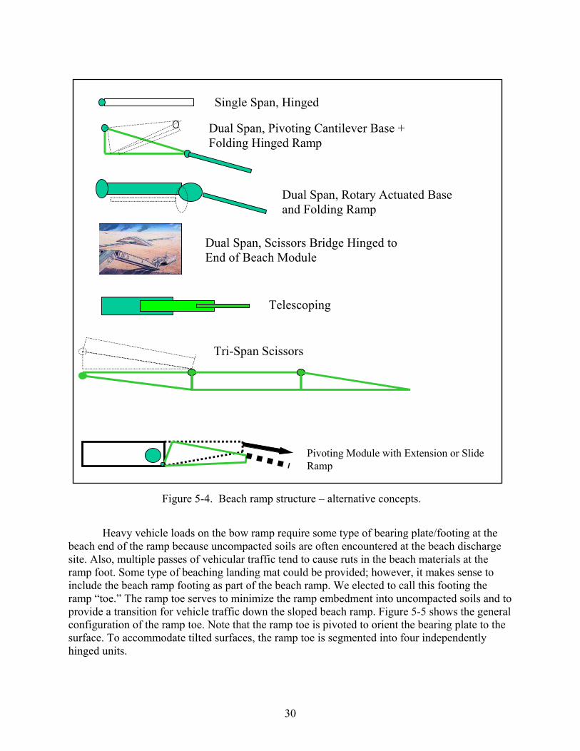
High capacity, reliability, relative simplicity, and familiarity of similar hydraulics in existing PHIBCB equipment drove the design team to choose hydraulic cylinders as the bow ramp deployment/retraction mechanism. Figure 5-4 shows several alternative configurations for the ramp structure. Single spans, folding spans, cantilever spans, and other variations were considered. When the final ramp length was determined, a single-hinged span provided sufficient structure and maintained the philosophy of simplicity.
29
Gin Pole and Winch
Cantilevered Sidewalls and Winch or Windlass
Hydraulic Rotary Actuators
Cantilever
Knuckle Boom Hydraulic Crane
Superstructure with Winch or Windlass
Slide and Pivot with Ski
Mobile Deployment Vehicle – Beach-Based or CF-Based
MGB Type
Figure 5-3. Beach ramp deployment/retraction alternative concepts.
30
Heavy vehicle loads on the bow ramp require some type of bearing plate/footing at the beach end of the ramp because uncompacted soils are often encountered at the beach discharge site. Also, multiple passes of vehicular traffic tend to cause ruts in the beach materials at the ramp foot. Some type of beaching landing mat could be provided; however, it makes sense to include the beach ramp footing as part of the beach ramp. We elected to call this footing the ramp “toe.” The ramp toe serves to minimize the ramp embedment into uncompacted soils and to provide a transition for vehicle traffic down the sloped beach ramp. Figure 5-5 shows the general configuration of the ramp toe. Note that the ramp toe is pivoted to orient the bearing plate to the surface. To accommodate tilted surfaces, the ramp toe is segmented into four independently hinged units.
Single Span, Hinged
Dual Span, Pivoting Cantilever Base + Folding Hinged Ramp
Dual Span, Rotary Actuated Base and Folding Ramp
Dual Span, Scissors Bridge Hinged to End of Beach Module
Telescoping
Tri-Span Scissors
Pivoting Module with Extension or Slide Ramp
Figure 5-4. Beach ramp structure – alternative concepts.
31
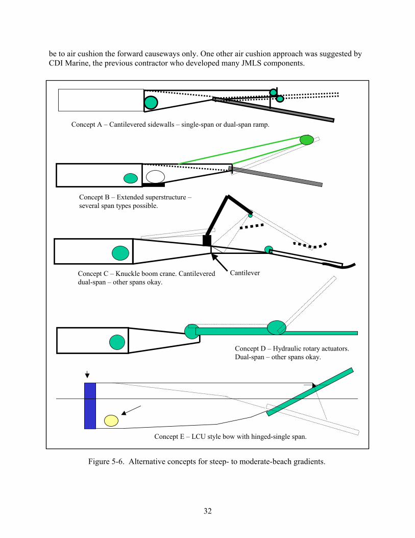
After the key functional elements of the bow ramp design were examined, the team generated alternative beach ramp/module concepts. The concepts for steep to moderate beach gradients are shown in Figure 5-6. As noted above, a number of concepts came from the brainstorming sessions. The military users of the SEABOSS systems provided a concept that suited their operational functions. Other concepts were a fallout of merged elements of concepts that were flawed in some way. Presentation of concepts to different audiences invariably elicited “improvements.” 5.2 CONCEPTS FOR MODERATE TO FLAT BEACH GRADIENTS A bow module designed to operate on steep to moderate beaches leaves a strategic gap in the operating capability to transfer cargo from ship to shore on flatter beaches. Clearly, it would be a logistic nightmare to fit the CF with a 100 to150-foot ramp capable of achieving even a wet ramp on beach gradients greater than 1:50. No amphibious lighter in history has accomplished such a feat. In essence, the requirement to land equipment on the beach led to the birth of the floating causeway system in World War II. The LSTs, which were medium small ships, needed a way to land the equipment for the Marine Corps. The difference now is only one of degree. The LSTs drew 6 to 8 feet of water at the bow, while the SEABOSS CF draws only 4 feet. The SEABOSS CF can land on steep beaches, but not on flatter beaches. The missing capability is unresolved.
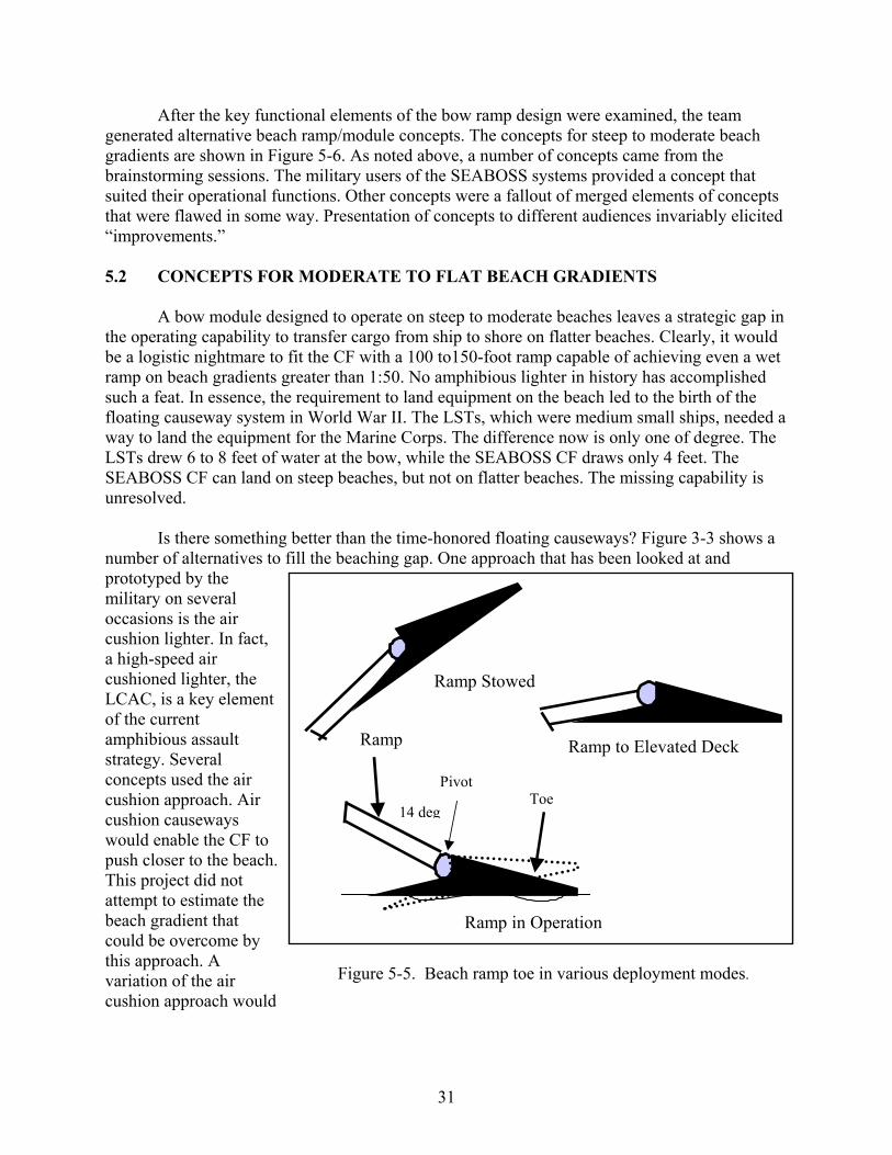
Is there something better than the time-honored floating causeways? Figure 3-3 shows a number of alternatives to fill the beaching gap. One approach that has been looked at and prototyped by the military on several occasions is the air cushion lighter. In fact, a high-speed air cushioned lighter, the LCAC, is a key element of the current amphibious assault strategy. Several concepts used the air cushion approach. Air cushion causeways would enable the CF to push closer to the beach. This project did not attempt to estimate the beach gradient that could be overcome by this approach. A variation of the air cushion approach would
Ramp
14 deg
Pivot Toe
Ramp Stowed
Ramp to Elevated Deck
Ramp in Operation
Figure 5-5. Beach ramp toe in various deployment modes.
32
be to air cushion the forward causeways only. One other air cushion approach was suggested by CDI Marine, the previous contractor who developed many JMLS components.
Cantilever
Concept A – Cantilevered sidewalls – single-span or dual-span ramp.
Concept B – Extended superstructure –several span types possible.
Concept C – Knuckle boom crane. Cantilevered dual-span – other spans okay.
Concept D – Hydraulic rotary actuators. Dual-span – other spans okay.
Concept E – LCU style bow with hinged-single span.
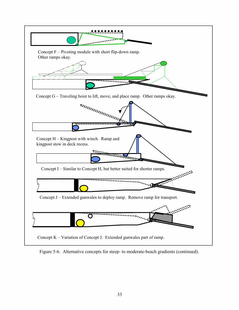
Figure 5-6. Alternative concepts for steep- to moderate-beach gradients.
33
Concept F – Pivoting module with short flip-down ramp. Other ramps okay.
Concept G – Traveling hoist to lift, move, and place ramp. Other ramps okay.
Concept H – Kingpost with winch. Ramp and kingpost stow in deck recess.
Concept I – Similar to Concept H, but better suited for shorter ramps.
Concept J – Extended gunwales to deploy ramp. Remove ramp for transport.
Concept K – Variation of Concept J. Extended gunwales part of ramp.
Figure 5-6. Alternative concepts for steep- to moderate-beach gradients (continued).

34
This page left blank.

35
Chapter 6
CONCEPT EVALUATION The concept evaluation was guided by the criteria for the specification, which are:
• Performance Criteria • Environmental Criteria • Logistics • Operational Considerations • SEABOSS Interfaces
Some of the bow ramp and bow module issues that will influence the selection process are:
• Backup beach ramp deployment/retraction method required for operational use. • Stacking of bow modules required for transport by MPR or LMSR shipping. • Maximum slope for other ramps include C5A, 13 degrees, and MPF(E), 15 degrees • Target bow ramp slope for 14 degrees on a flat beach. Ramp slope decreases as beach
slope gets steeper. • Bottom rake of bow module will affect additional trim toward bow. • Bow thruster weight is unlikely to provide level trim in 80-foot bow module. • Ramp module trim must be near level to connect to other CF modules. • Other design considerations of the bow module may be necessary to enable flex
connection to CF modules. Tapering the flex end and lowering the flex connector is one option.
Members of the SEABOSS design team that developed the bow module alternative concepts participated in the evaluation and down selection of the alternatives. 6.1 TRADE-OFF ANALYSES
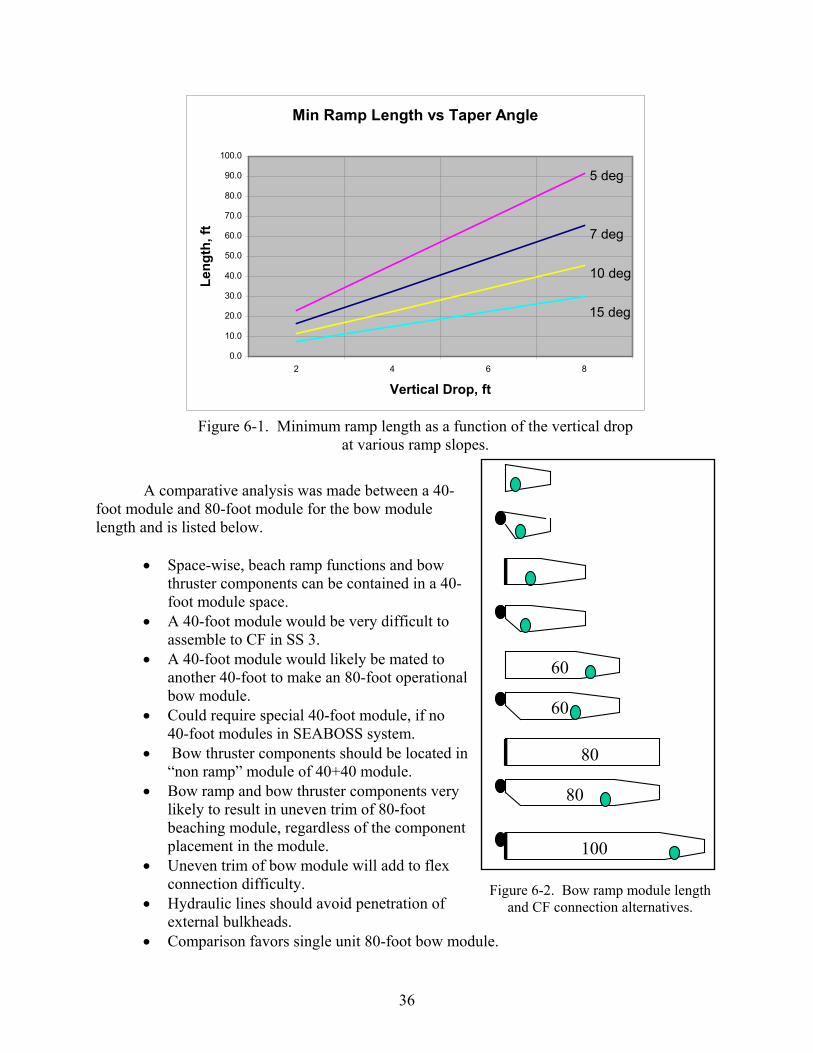
A number of trade-off analyses were conducted to evaluate key components or subsystems of the bow module system. One of the leading trade-offs was the selection of the bow module configuration. Figure 6-1 graphs the minimum ramp length required for various slopes and vertical drops. This data was used to consider the height of the bow ramp hinge on the module and the deck taper angle. Figure 6-2 shows some bow module configurations that were considered.
36
60
60
80
80
100
Figure 6-2. Bow ramp module length
and CF connection alternatives.
A comparative analysis was made between a 40-foot module and 80-foot module for the bow module length and is listed below.
• Space-wise, beach ramp functions and bow
thruster components can be contained in a 40-foot module space.
• A 40-foot module would be very difficult to assemble to CF in SS 3.
• A 40-foot module would likely be mated to another 40-foot to make an 80-foot operational bow module.
• Could require special 40-foot module, if no 40-foot modules in SEABOSS system.
• Bow thruster components should be located in “non ramp” module of 40+40 module.
• Bow ramp and bow thruster components very likely to result in uneven trim of 80-foot beaching module, regardless of the component placement in the module.
• Uneven trim of bow module will add to flex connection difficulty.
• Hydraulic lines should avoid penetration of external bulkheads.
• Comparison favors single unit 80-foot bow module.
Min Ramp Length vs Taper Angle
0.0
10.0
20.0
30.0
40.0
50.0
60.0
70.0
80.0
90.0
100.0
2 4 6 8
Vertical Drop, ft
Leng
th, f
t
5 deg
15 deg
10 deg
7 deg
Figure 6-1. Minimum ramp length as a function of the vertical drop
at various ramp slopes.
37
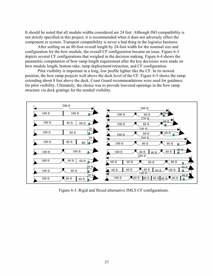
It should be noted that all module widths considered are 24 feet. Although ISO compatibility is not strictly specified in this project, it is recommended when it does not adversely effect the component or system. Transport compatibility is never a bad thing in the logistics business.
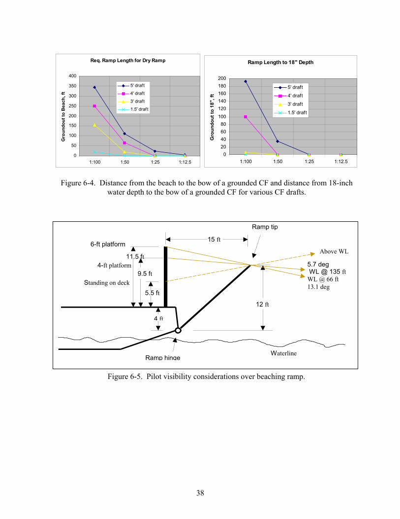
After settling on an 80-foot overall length by 24-foot width for the nominal size and configuration for the bow module, the overall CF configuration became an issue. Figure 6-3 depicts several CF configurations that weighed in the decision making. Figure 6-4 shows the parametric computation of bow ramp length requirement after the key decisions were made on bow module length, bottom rake, ramp deployment/retraction, and CF configuration. Pilot visibility is important in a long, low profile lighter like the CF. In its stowed position, the bow ramp projects well above the deck level of the CF. Figure 6-5 shows the ramp extending about 8 feet above the deck. Coast Guard recommendations were used for guidance for pilot visibility. Ultimately, the choice was to provide louvered openings in the bow ramp structure via deck gratings for the needed visibility.
100 ft
100 ft 40 ft
40 ft
100 ft 40 40 ft
60 ft
20 ft
100 ft 40 ft 20 ft
40 ft
200 ft
100 ft 100 ft
100 ft 100 ft
60 ft
100 ft 80 ft
100 ft 80 ft 20 ft
20 ft
260 ft
240 ft
220 ft
200 ft
280 ft
60 ft
100 ft
100 ft
100 ft
100 ft
80 ft 60 ft
80 ft
80 ft
80 ft
80 ft 20 ft
40 ft
60 ft
80 ft
100 ft 40 ft 40 ft40 ft 40 ft
80 ft
60 ft 40 ft 60 ft 40 ft
40 ft 40 ft
100 ft 40 ft 40 ft 40 ft 40 ft 40 ft
40 ft 340 ft
Figure 6-3. Rigid and flexed alternative JMLS CF configurations.
38
Req. Ramp Length for Dry Ramp
0
50
100
150
200
250
300
350
400
1:100 1:50 1:25 1:12.5
Gro
undo
ut to
Bea
ch, f
t
5' draft
4' draft
3' draft
1.5' draft
Ramp Length to 18" Depth
020406080
100120140160180200
1:100 1:50 1:25 1:12.5
Gro
undo
ut to
18"
, ft
5' draft
4' draft
3' draft
1.5' draft
Figure 6-4. Distance from the beach to the bow of a grounded CF and distance from 18-inch
water depth to the bow of a grounded CF for various CF drafts.
Ramp tip
Ramp hinge
12 ft
15 ft
5.5 ft
9.5 ft
11.5 ft Above WL
5.7 deg WL @ 135 ft WL @ 66 ft 13.1 deg
4 ft
6-ft platform
4-ft platform
Standing on deck
Waterline
Figure 6-5. Pilot visibility considerations over beaching ramp.
39
Table 6-1. Alternatives for a Backup Beaching Ramp Deployment/Retraction System
Alternative Description Use existing hydraulic cylinders
Insert portable hydraulic pump to power existing cylinders locally.
Threaded rod jacking mechanism
Use turn-of-nut or worm gear drives to power threaded rods. Replace existing cylinders.
Mechanical leverage Use block-and-tackle or other leverage to retract ramp via securing padeyes.
Pivot lever Use hinged pivot to gain leverage to retract ramp. Winch or come-a-long provide power.
Port-a-power Use portable hydraulic cylinders in place of existing hydraulic cylinders.
Repair/replace Develop high level repair capability and deploy spares for critical systems.
Table 6-2. Failure Modes Analysis of JMLS Beaching Ramp System
Failure
Probability of Failure
Onboard Spare
Probable Fix During Operation
Prime mover Low No Repair Hydraulic pump Medium low Yes Replace Hydraulic reservoir Medium low No Repair Hydraulic lines Medium low Yes Replace Fluid contamination Medium high Yes Repair Hydraulic cylinder Low Yes? Replace Hydraulic hose High Yes Replace Hydraulic valves Medium high Yes Replace Hydraulic flow divider Medium low Yes Replace Ramp damage Low No Repair Securing system damage Medium Yes Replace Padeye damage Medium low No Repair

40
Table 6-3. Assessment of Alternatives for Beaching Ramp Failure Modes
Failure
Probability of Failure
Spare
Fix
Does Alternative Fix the Failure?
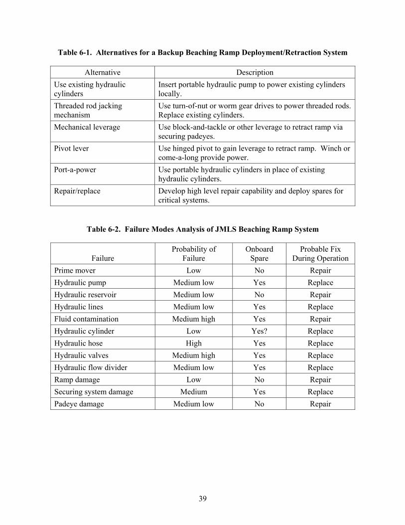
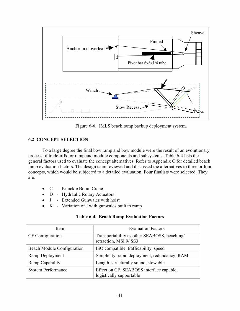
A B C D E F Prime mover Low No Repair Y Y Y Y Y ? Hydraulic pump Medium low Yes Replace Y Y Y Y Y Y Hydraulic reservoir Medium low No Repair Y Y Y Y Y ? Hydraulic lines Medium low Yes Replace Y Y Y Y Y Y Fluid contamination Medium high Yes Repair N Y Y Y N Y Hydraulic cylinder Low Yes? Replace N Y Y Y Y Y? Hydraulic hose High Yes Replace Y Y Y Y Y Y Hydraulic valves Medium high Yes Replace Y Y Y Y Y Y Flow divider Medium low Yes Replace Y Y Y Y Y Y Ramp Low No Repair N N N N N N Security system Medium No Repair N N N N N Y Padeye Medium low No Repair N N Y Y N Y The backup deployment/retraction system for the bow ramp proved to be one of the more difficult design decisions to make in the project. The CF is a critical element of ship-to-shore logistics. It is unacceptable for failure of the primary deployment/retraction system to completely disable the CF. Table 6-1 shows several alternative approaches. A failure modes analysis was performed on the bow module to help determine which alternative would address the most failures. Table 6-2 shows the primary failure modes anticipated. Each of the alternatives of Table 6-1 was assessed against the failure modes of Table 6-2. The results are presented in Table 6-3. The pivot lever concept was judged to provide the best overall solution. Figure 6-6 is a schematic of the pivot lever alternative.
41
6.2 CONCEPT SELECTION
To a large degree the final bow ramp and bow module were the result of an evolutionary process of trade-offs for ramp and module components and subsystems. Table 6-4 lists the general factors used to evaluate the concept alternatives. Refer to Appendix C for detailed beach ramp evaluation factors. The design team reviewed and discussed the alternatives to three or four concepts, which would be subjected to a detailed evaluation. Four finalists were selected. They are:
• C - Knuckle Boom Crane • D - Hydraulic Rotary Actuators • J - Extended Gunwales with hoist • K - Variation of J with gunwales built to ramp
Table 6-4. Beach Ramp Evaluation Factors
Item Evaluation Factors
CF Configuration Transportability as other SEABOSS, beaching/ retraction, MSI 9/ SS3
Beach Module Configuration ISO compatible, trafficability, speed Ramp Deployment Simplicity, rapid deployment, redundancy, RAM Ramp Capability Length, structurally sound, stowable System Performance Effect on CF, SEABOSS interface capable,
logistically supportable
.Winch
Pinned
Stow Recess
Pivot bar 6x6x1/4 tube
Sheave
Anchor in cloverleaf
Figure 6-6. JMLS beach ramp backup deployment system.
42
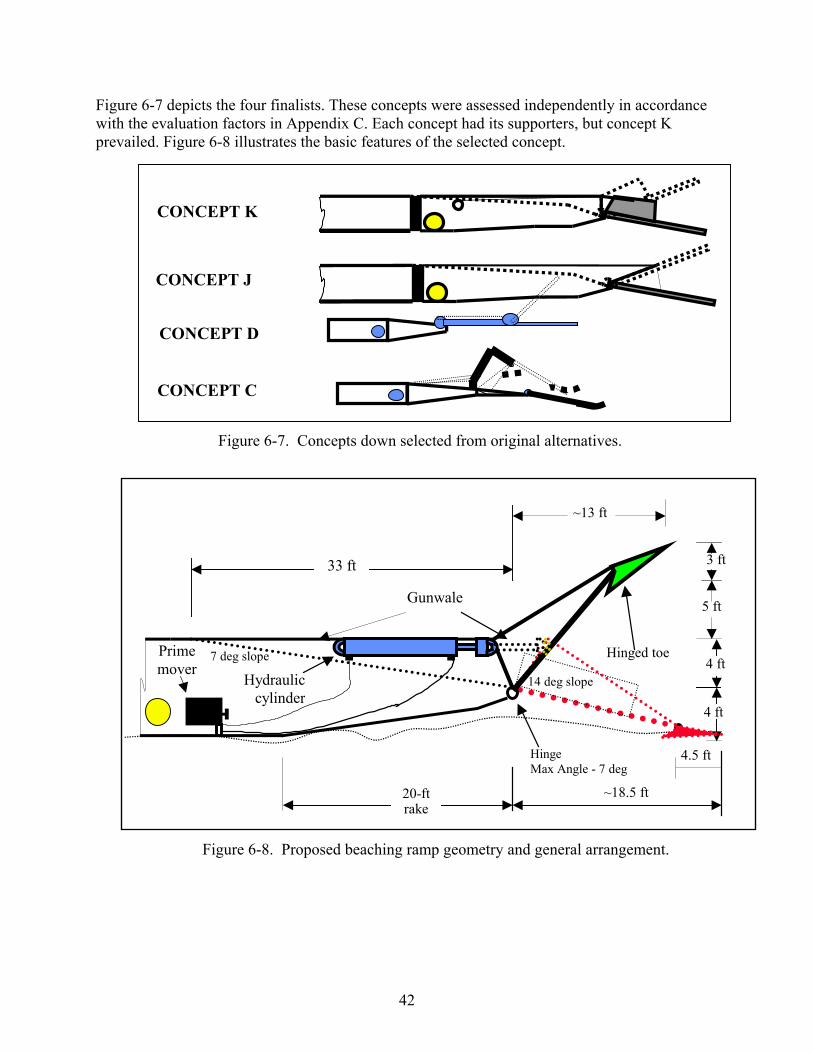
Figure 6-7 depicts the four finalists. These concepts were assessed independently in accordance with the evaluation factors in Appendix C. Each concept had its supporters, but concept K prevailed. Figure 6-8 illustrates the basic features of the selected concept.
CONCEPT K
CONCEPT J
CONCEPT D
CONCEPT C
Figure 6-7. Concepts down selected from original alternatives.
7 deg slope
33 ft
4 ft
Hinge Max Angle - 7 deg
~18.5 ft 20-ftrake
4 ft
4.5 ft
Gunwale
14 deg slope
Hinged toe
Hydrauliccylinder
~13 ft
Prime mover
5 ft
3 ft
Figure 6-8. Proposed beaching ramp geometry and general arrangement.
43
Chapter 7
DESIGN EXECUTION The development process for the bow module was quite extensive for this project. Initially, the operational needs and the environmental factors were explored with the military users to get a better perspective of the system to be developed. A review of beaching ramps and related applications, going back to the origination of the Navy’s pontoon causeway in World War II, revealed what has been used in the past and how successful (or unsuccessful) they are. Military users were consulted to determine their future needs and to review their “lessons learned” of the past. From this data and other analyses, the beaching ramp criteria were refined for this SEABOSS application. The design team concluded that two approaches are required for the range of steep to flat slopes. At beach slopes less than 1:50, ramp lengths remain reasonable, while flatter beach slopes would require ramps of 100 feet or more. For flatter beaches, floating causeways should span the shallow gap to interface with the CF bow module. Trade-offs pared down the list of alternatives, leading to the concept selected for detailed design.
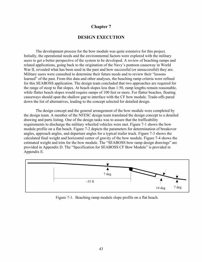
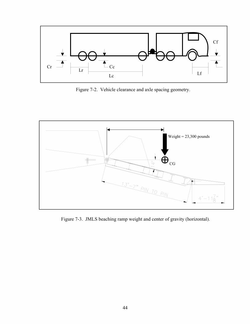
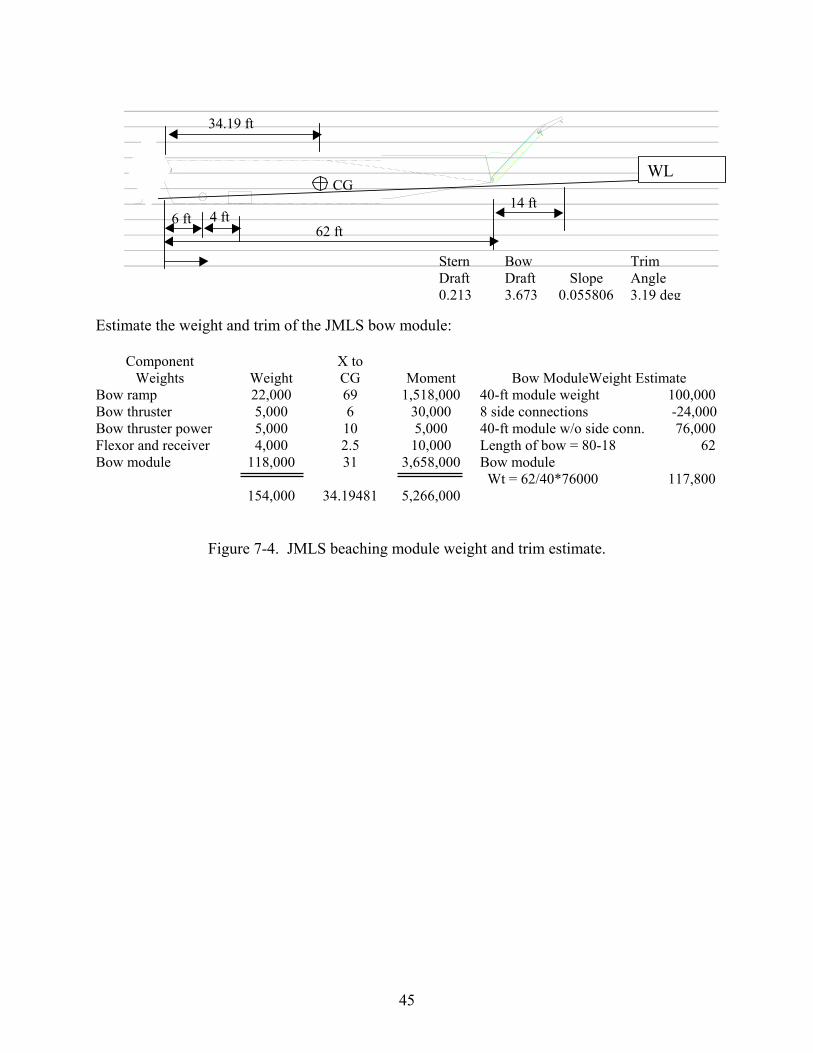
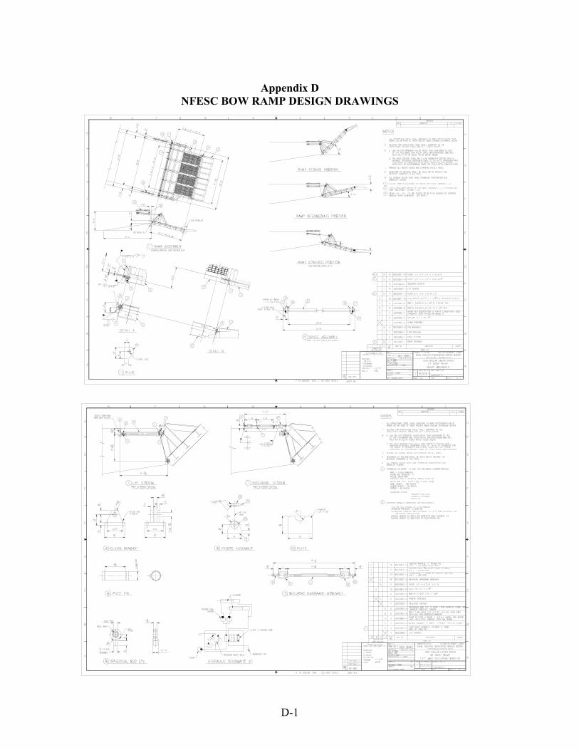
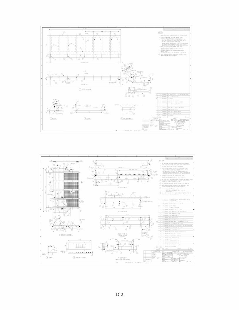
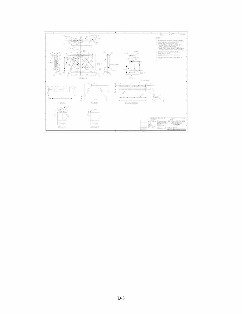
The design concept and the general arrangement of the bow module were completed by the design team. A member of the NFESC design team translated the design concept to a detailed drawing and parts listing. One of the design tasks was to assure that the trafficability requirements to discharge the military wheeled vehicles were met. Figure 7-1 shows the bow module profile on a flat beach. Figure 7-2 depicts the parameters for determination of breakover angles, approach angles, and departure angles for a typical trailer truck. Figure 7-3 shows the calculated final weight and horizontal center of gravity of the bow module. Figure 7-4 shows the estimated weight and trim for the bow module. The “SEABOSS bow ramp design drawings” are provided in Appendix D. The “Specification for SEABOSS CF Bow Module” is provided in Appendix E.
~33 ft
7 deg
14 deg 7 deg
Figure 7-1. Beaching ramp module slope profile on a flat beach.
44
CcCr
Cf
Lr Lc Lf
Figure 7-2. Vehicle clearance and axle spacing geometry.
Weight = 23,300 pounds
CG
Figure 7-3. JMLS beaching ramp weight and center of gravity (horizontal).
45
Estimate the weight and trim of the JMLS bow module:
Component Weights
Weight
X to CG
Moment
Bow ModuleWeight Estimate
Bow ramp 22,000 69 1,518,000 40-ft module weight 100,000 Bow thruster 5,000 6 30,000 8 side connections -24,000 Bow thruster power 5,000 10 5,000 40-ft module w/o side conn. 76,000 Flexor and receiver 4,000 2.5 10,000 Length of bow = 80-18 62 Bow module 118,000
154,000
31
34.19481
3,658,000
5,266,000
Bow module Wt = 62/40*76000 117,800
Figure 7-4. JMLS beaching module weight and trim estimate.
62 ft
14 ft 6 ft
CGWL
34.19 ft
4 ft
Stern Bow Trim Draft Draft Slope Angle 0.213 3.673 0.055806 3.19 deg

46
This page left blank.

47
Chapter 8
BIBLIOGRAPHY AFSC. Design Handbook DH 1-11, Air Transportability, Dept. of the Air Force, Aeronautical Systems Division, Wright-Patterson Air Force Base, 15 June 1983. MAR, Inc., Technical Report No. 960 “ELCAS Installation on Shallow Beach Gradients,” August 1990, Severna Park, MD (DTRC Contract No. N00167-86-D-0119/0114). Marine Corps. Technical Manual, TM 11275-15/3c, “Principal Technical Characteristics of U.S. Marine Corps Engineer Equipment,” September 1991. Marine Corps. Technical Manual, TM 11240-15/4B, August 1994. Marine Corp. Technical Manual, Motor Transport Technical Characteristics Manual. Naval Civil Engineering Laboratory. Technical Memorandum No. 55-83-10. A Lightweight Ramp for Amphibious Missions, by B. R. Karrh, November 1983. Naval Civil Engineering Laboratory. Memorandum “Beach Ramp Concept Study for the Navy’s Elevated Causeway System,” September 1979 (unpublished). Naval Facilities Engineering Command. MIL-HDBK-1791, Handbook for Designing for Internal Aerial Delivery of Fixed Wing Aircraft. Naval Facilities Engineering Service Center. Memorandum “NL Articulating Ramp,” of 27 May 1998, by P. R. Kane and B.R. Karrh, Port Hueneme, California. Naval Sea Systems Command (PMS 385). “Circular of Requirements for Conversion of an Existing Ship to an Enhanced Maritime Pre-Positioning Force Ship, MPF(E),” Arlington, Virginia, November 1995. Operational Requirements Document for Joint Modular Lighter System (JMLS), Version 6, 11/17/00 [draft].

48
This page left blank.

A-1
Appendix A
CAUSEWAY FERRY MOMENTUM BEACHING ANALYSIS MOMENTUM BEACHING ANALYSIS OF FLEXED CF @
4 FEET DRAFT
Draft= 1.5 3 3 57.24763W1= 184320 W2= 368640 W3= 414720 Friction Factor= 0.5
N= normal force= f(x) Speed= 6 knots = 10.13333 f/sec dT= 0.1 Beach Slope= 1:50= 0.01 0.578 deg Thrust, P= 20,000 lb
Station T+dT Vi Xi-1 Xi Yi Ri Ai Xi+1
-1 -0.1 0 0 10.13333 -1.01333 0 0 0 0 1.0133331 0.1 10.13333 0 1.013333 0.010133 -311.296 -0.01036 2.0265632 0.2 10.1323 1.013333 2.026563 0.020266 -618.471 -0.02058 3.0395873 0.3 10.13024 2.026563 3.039587 0.030396 -921.55 -0.03067 4.0523044 0.4 10.12717 3.039587 4.052304 0.040523 -1220.56 -0.04061 5.0646155 0.5 10.12311 4.052304 5.064615 0.050646 -1515.52 -0.05043 6.0764226 0.6 10.11807 5.064615 6.076422 0.060764 -1806.47 -0.06011 7.0876287 0.7 10.11206 6.076422 7.087628 0.070876 -2093.42 -0.06966 8.0981378 0.8 10.10509 7.087628 8.098137 0.080981 -2376.42 -0.07908 9.1078569 0.9 10.09718 8.098137 9.107856 0.091079 -2655.49 -0.08836 10.11669
10 1 10.08835 9.107856 10.11669 0.101167 -2930.67 -0.09752 11.1245511 1.1 10.0786 10.11669 11.12455 0.111245 -3201.98 -0.10655 12.1313412 1.2 10.06794 11.12455 12.13134 0.121313 -3469.45 -0.11545 13.1369813 1.3 10.0564 12.13134 13.13698 0.13137 -3733.13 -0.12422 14.1413814 1.4 10.04397 13.13698 14.14138 0.141414 -3993.05 -0.13287 15.1444515 1.5 10.03069 14.14138 15.14445 0.151444 -4249.24 -0.1414 16.146116 1.6 10.01655 15.14445 16.1461 0.161461 -4501.74 -0.1498 17.1462617 1.7 10.00157 16.1461 17.14626 0.171463 -4750.59 -0.15808 18.1448418 1.8 9.98576 17.14626 18.14484 0.181448 -4995.81 -0.16624 19.1417519 1.9 9.969136 18.14484 19.14175 0.191418 -5237.45 -0.17428 20.1369220 2 9.951708 19.14175 20.13692 0.201369 -5475.55 -0.1822 21.1302721 2.1 9.933488 20.13692 21.13027 0.211303 -5710.13 -0.19001 22.1217222 2.2 9.914487 21.13027 22.12172 0.221217 -5941.25 -0.1977 23.1111923 2.3 9.894717 22.12172 23.11119 0.231112 -6168.94 -0.20527 24.0986124 2.4 9.87419 23.11119 24.09861 0.240986 -6393.24 -0.21274 25.083925 2.5 9.852916 24.09861 25.0839 0.250839 -6614.18 -0.22009 26.0669926 2.6 9.830907 25.0839 26.06699 0.26067 -6831.81 -0.22733 27.0478127 2.7 9.808174 26.06699 27.04781 0.270478 -7046.16 -0.23446 28.0262828 2.8 9.784728 27.04781 28.02628 0.280263 -7257.27 -0.24149 29.0023429 2.9 9.760579 28.02628 29.00234 0.290023 -7465.18 -0.24841 29.9759130 3 9.735738 29.00234 29.97591 0.299759 -7669.94 -0.25522 30.9469431 3.1 9.710216 29.97591 30.94694 0.309469 -7871.57 -0.26193 31.9153432 3.2 9.684023 30.94694 31.91534 0.319153 -8070.12 -0.26854 32.8810533 3.3 9.657169 31.91534 32.88105 0.328811 -8265.63 -0.27504 33.8440234 3.4 9.629665 32.88105 33.84402 0.33844 -8458.13 -0.28145 34.80417
Sample computation for numerical analysis of momentum beaching of a causeway at 6 knots (full speed).

A-2
This page left blank.
B-1
APPENDIX B
TRAFFICABILITY ANALYSIS
Breakover Angle Interference
0
2
4
6
8
10
12
14
16
18
20
0 50 100 150 200 250 300Axle Spacing, in
Inte
rfer
ence
by
Bre
akov
er A
ngle
, in
5* BO angle
10* BO angle
15* BO angle
Departure Angle Interference
02468
101214
0 20 40 60 80 100Overhang, in
Inte
rfer
ence
by
Dep
. A
ngle
, in.
5* BO angle
10* BO angle
15* BO angle
B-2
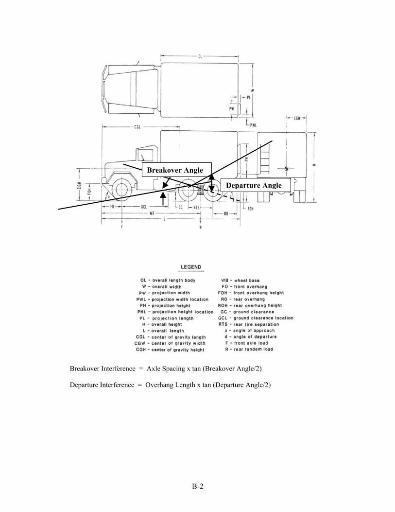
Breakover Interference = Axle Spacing x tan (Breakover Angle/2)
Departure Interference = Overhang Length x tan (Departure Angle/2)
Breakover Angle
Departure Angle

C-1
Appendix C
CONCEPT SELECTION CRITERIA BOW MODULE EVALUATION FACTORS
Weight Factor
A. CF Configuration 1 . Transportable by military shipping - size, weight, stow, deploy 2 . Capability to be assembled into CF in SS 3 3 . Capability to transport 400 ST of cargo in SS 3 4 . Capability to attain 6 knot speed fully loaded in SS 3 5 . Capability to dock and hold position @ ELCAS and ships in SS 3 6 . Capability for unassisted beaching/retracting - fully loaded on slopes to 1:50 7 . Capability to withstand surf to MSI 9 surf when beached 8 . Capabilty for dozer assisted beaching/retracting 9 . Capability to interface with other SEABOSS systems (RRDF, FC) B. Beach Module Hull Configuration 1 . Transportable by military shipping - size, weight, stow, deploy 2 . Capability for assembly into CF in SS 3 3 . Capability to contain ramp, deployment equipment, bow thruster 4 . Capability to load/offload military vehicles when beached and interfacing with RRDF and FC 5 . Capabilty of bow to slide over beach gradients rather than plowing in 6 . Capability to discharge military vehicles to beach and other SEABOSS
systems 7 . Hydrodynamic response of module C. Ramp Deployment Mode 1 Simplicity of operation 2 Rapid deployment capability 3 Backup deployment mode 4 Dozer push compatible 5 Operationally compatible 6 Reliable, maintainable D. Ramp Capability 1 Beach gap length capability 2 Deployability 3 Durability 4 Stowability 5 Structural capability 6 Toe bearing capability 7 Bow function capability 8 Dozer push compatible 5. Weight < Twin Crane Capacity B. Logistics Impact

C-2
� Beach ramp configuration and properties, including length required to meet beach gradient requirements per the ORD � General hull form (length, width, weight, draft, flexibility, geometry) and its impact on beaching � Trafficability of beach ramp geometry (break-over angles) � Deployment mechanism, powered or non-powered � Bow thruster � Type, size, and placement � Use of thrusters (bow and/or propulsion) to move sand as a dredge
The following performance factors will be used to evaluate alternatives:
� Effect on assembly of the SEABOSS CF � Ability to discharge cargo on beaches with steep or flat Gradients � Time to deploy and retract � Ability to operate in current, tides, surf conditions (MSI 9), waves, and wind � Ability to breach surf zone obstructions, sand bars, and reefs � Ability to interface with other SEABOSS systems, such as the RRDF, FC, and other water craft without degrading their performance � Logistics impact � Cost
D-1
Appendix D
NFESC BOW RAMP DESIGN DRAWINGS
D-2
D-3

D-4
This page left blank.
E-1
Appendix E
SPECIFICATION FOR SEABOSS CF BOW RAMP MODULE
000 GENERAL GUIDANCE AND ADMINISTRATION 70 General Requirements for Design and Construction - General Guidance and
Administration from the _______ (system spec) specification shall apply to the Causeway Ferry (CF) Bow module (BM). The bow module and bow ramp shall be designed to the structural and hydrodynamic specifications of standard SEABOSS modules as listed in Specification ______(spec for deck and hull design loads for standard SEABOSS modules). Generally, the requirements specified herein will be in addition to the specifications for standard SEABOSS modules, although some specifications may be repeated to assure clarity. A government developed design concept for a CF bow module is provided for information only in Appendix As. A list of acronyms and definitions used in this specification is provided in Appendix Bs. Appendix Cs provides a list of lessons learned from previous beach ramp design applications. Vehicle types to transit the BM include tractor (e.g., USMC type M818 or M931A2)/trailer (e.g. USMC M870 or M870A1 type) with fully loaded 40-foot container, Rough Terrain Container Handler (RTCH) unloaded, 5-Ton Stake Truck, HUMMVEE, water buffalo, Heavy Equipment Trailer (HET), M1A1 Tank, USMC Logistics Vehicle System (LVS) MK48. Appendix Ds (from reference 2) lists USMC motor transport vehicles. Appendix Es is a list of reference documents used to assist the development of this specification.
92 Shipboard Tests – For shipboard tests components may be tested as part of the bow module. These tests shall be performed after installation of the component in the BM.
92.1 Bow Thruster Functional Test – The installed bow thruster system shall be tested for functional performance and operation of the controls prior to ship trials. Performance characteristics of the thruster and engine shall be validated by the respective manufacturers. 92.2 Bow Ramp Functional Tests – The installed bow ramp shall be tested for functional and operational performance prior to ship trials using the onboard control system. Representative military vehicles, including the Rough Terrain Container Handler (RTCH) and the Army’s Heavy Equipment Trailer (HET) (if available), shall load and discharge over the bow ramp at positions representative of flat beaches, steep beaches, and a pier deck two feet above the bow module deck.
94 Ship Trials – For ship trials the bow module shall be tested as an integral part of the SEABOSS causeway ferry. Testing shall include transportability of modules by Military Pre-positioned Force (MPF) shipping. Trials shall be conducted under conditions that permit evaluation of performance in sea state 3 and Modified Surf Index (MSI) 11.
94.1 Transportability Testing – Ship trials for transportability by MPF shipping shall include lifting modules by MPF crane(s), stacking modules on deck, securing for transport, offloading over the side, and assembly of the CF while afloat.
E-2
94.2 Speed Trials – CF speed trials shall include runs fully loaded (400 ST) and unloaded and with and without the bow module to determine that BM does not degrade the speed of the CF by more than 5 % for each condition. 94.3 Beaching Trials – The CF shall demonstrate the capability to retract from the beach under all beaching conditions and tidal ranges. A fully loaded CF with the bow ramp shall beach on flat (1:50 slope) and steep (1:10 slope) beaches to determine the ability to achieve a “dry ramp.” The CF may approach the beach at any speed up to full speed (6 knots) to achieve the dry ramp. A “dry ramp” requires that the water depth at the end of the bow ramp does not exceed 18 inches, which can be forded by military vehicles expected to use the ramp. The bow ramp shall be fully deployed from a stowed position to ready to discharge vehicles in each of the above scenarios. After each beaching trial, the bow ramp shall be retracted to the fully stowed position and the CF shall retract from the beach. Assist by dozers or warping tug is allowed for retraction only. 94.4 Docking Trials – The CF with the bow module shall demonstrate the capability to dock and moor at the SEABOSS Roll-on/Roll-off Discharge Facility (RRDF), the Navy Lightered (NL) RRDF, the Modular Causeway System (MCS) RRDF, the NL Floating Causeway (FC), the SEABOSS FC, the MCS FC and similar floating platforms up to two feet higher than the hinge point of the BM. 94.5 Vehicle load and discharge tests – Military vehicles, including the RTCH and the dozer, shall be loaded and discharged over the bow ramp under conditions representative of flat beaches (as in Beaching Trials), steep beaches, and a pier deck two feet above the bow ramp hinge point (as in Docking Trials). These tests may be performed in conjunction with the beaching and docking trials above.
95 Test Requirements – Assets, facilities, personnel, resources, and support equipment required to execute the Shipboard Tests and the Ship Trials are identified in this section.
95.1 Transportability Tests – These tests require an MPF ship, dock access, other SEABOSS modules, operators and support tugs, stacking dunnage, tie-downs, mooring and rigging gear, CF modules, 95.2 Speed Trials - Operators and support tugs, modules for complete CF, measured course, dock access, ballast material 95.3 Beaching Trials - Operators and support tugs, modules for complete CF, beach support equipment, beach access, dock access, ballast material 95.4 Docking Trials - Operators and support tugs, modules for complete CF, floating platform with deck two feet higher than bow module deck (RRDF, FC, etc.), dock access, 95.5 Vehicle load and discharge tests – Representative military equipment (6-8 units), RTCH, Dozer, and HET (if available).
HULL STRUCTURE
100 General Requirements for Hull Structure 100.1 When stowed, the bow ramp shall be integrated into the bow module hull such
that it functions as the bow of the causeway ferry (CF) while underway. The angle or shape of the bow ramp shall minimize form drag resistance on the CF, insofar as other operational requirements are not compromised.
100.2 The arrangement of the bow thruster and other components in the BM shall effect draft and trim in a manner to enhance connection to an adjacent SEABOSS floating causeway
E-3
module with the SEABOSS flexible connectors, insofar as other criteria are not significantly impacted.
100.3 The BM shall have the capability to interface with the flexible connection system to be designed for CF modules; the bow module stern shear connector shall be of the female receiver type. See Section ____.
100.4 By arranging the loads on the CF, the BM shall be capable of attaining a hull bottom trim parallel to any beach gradient from 0 to 1:30.
100.5 Deck breakover angles on the BM departure roadway and between the departure roadway and the bow ramp shall not exceed 7 degrees; length between successive breakover angles shall be 20 feet or more. 100.6 Maximum slope of the bow module departure pathway and the bow ramp shall not
exceed 14 degrees from horizontal when discharging onto a near zero gradient beach. 100.7 The BM shall be capable of achieving a "dry ramp" on mud or sandy beaches
with beach gradients of 1:50 or less. See DEFINITIONS in Appendix Bs for "dry ramp". 100.9 Military Vehicle Trafficability Requirements 100.9.1 Definitions for trafficability requirements shall be as defined by the sketch shown in Appendix Ds. 100.9.2 The bow ramp and bow module shall be capable of discharging and embarking military vehicular cargo to the beach, the SEABOSS RRDF, or the FC ramp module at all operational drafts. The bow module shall be capable of discharging and embarking the US Army’s Heavy Equipment Trailer (HET) under limited conditions suitable for operation of the HET. 100.10 When used as part of the CF, the bow ramp hinge shall not be fully submerged below the still water level at all CF load conditions (generally 4 feet maximum draft). 100.11 The bow ramp design shall provide for forward navigation visibility by CF operators during transit, maneuvering, docking, and beaching to enable safe operations.
100.11.1 For CF underway transit, use guidance provided by the US Coast Guard for passenger vessels over 328 feet long: “CG 46CFR Chapter 1 Subpart 72.04 – Navigation Bridge Visibility”. This guidance specifies that the forward arc of visibility shall have no blind sector greater than 5 degrees caused by permanent obstructions. 100.11.2 For beaching, maneuvering and docking around other vessels and floating facilities, provision shall be made for visibility by a forward lookout. The lookout shall have direct wireless radio communication to the navigation bridge. 100.12 Fendering for the bow module shall be of the type and design as the
standard SEABOSS modules (Specification ______). 100.12.1 Fendering shall be provided to protect the bow module while
docking or when moored alongside ships, warping tugs, NL causeways, MCS, and SEABOSS RRDF and FC in sea state 3. 100.13 Deck Hardware for the bow module shall be of the same type and
capacity as the standard SEABOSS modules. See Specification ______. 100.13.1 Vehicle tie-down fittings shall be located on the deck of the bow
module (including the sloped deck) in the same pattern as the standard SEABOSS module, except for differences necessitated by overall length variations. 100.13.2 A total of six (6) portable bitts shall be mounted on the bow module deck as follows: one bitt on each side 10 feet from the stern; 1 bitt on each side 40
E-4
feet from the stern; 1 bitt on each gunwale 10 feet from the bow. The bitts shall be 12-18 inches inboard from the side hull, except the two bitt locations on the gunwales may be adjusted for geometric and structural necessity. The bitts shall be the same type and capacity of those of standard SEABOSS modules. See Specification ______. 100.13.3 Two (2) [open or closed?] ___ -inch chocks, one on each gunwale, shall be mounted at about two feet from the bow end of the gunwales. The chocks shall be located flush with the outboard edge for proper fairlead in all directions. The chocks shall be the same type and capacity of those of standard SEABOSS modules. See Specification ______. 100.13.4 Four (4) lifting eyes, designed for a single-point lift 20 feet above the deck, shall be mounted on the deck for lifting the bow module by MPF pedestal cranes in sea state 3. The lifting eyes shall be compatible with MPF and travel lift sling gear. The lifting eyes shall be located to get the center of gravity beneath the crane hook using standard SEABOSS lifting slings.
100.14 Lifelines shall be of the type specified for standard SEABOSS modules. They shall be made of Kevlar with bendable stanchions, including a waist rope and a hip rope with sister hooks.
100.15 The bow module shall be capable of push tow by the SEABOSS warping tug to enable maneuvering for CF assembly.
100.16 Bow and stern rake angles of the bow module shall be selected to minimize form and drag resistance or for compatibility with the flexible connector, as appropriate. The bow rake shall be formed to enhance the ability to slide up the beach when the CF beaches at speed. The bow rake angle may be modified to enhance beaching of the CF. 100.17 The bow module shall have a hard point on the bow to enable dozers to assist retraction of the CF by pushing. 111 Shell Plating 111.1 The leading edge of the raked bow end of bow module shall be shaped so that the
module will slide over the bottom upon contact with the beach (rather than digging into the bottom) when beaching/retraction of the CF.
116 Framing for Shell Plating and Innerbottoms shall be designed for the environmental and
operational forces specified for the standard SEABOSS modules. See Specification ______. 116.1 The bottom hull plate and framing shall be designed to resist the forces from beaching a fully loaded CF at 10 knots. Multiple beach landings and corrosion shall not degrade the structural integrity of the bottom hull plate shell over the 20-year life of the module.
130 Decks and Platforms 130.1 Bow Ramp 130.1.1 The bow module shall be capable of discharging and embarking military
vehicular cargo to the beach, the SEABOSS RRDF, or the FC ramp module at all operational drafts, including US Army’s Heavy Equipment Trailer (HET) under limited conditions suitable for operation of the HET.

E-5
130.1.2 The deck breakover angle between the departure roadway and the bow ramp shall not exceed 7 degrees.
130.1.3 Maximum slope of the bow module departure pathway and the bow ramp shall not exceed 14 degrees from horizontal when discharging onto a near zero gradient beach.
130.1.4 The bow module design shall provide a roadway width of no less than 22 feet over its full length.
130.1.5 The width of the bow ramp along its full length shall not be less than the width of the RTCH plus 4 feet.
130.1.6 Bow Ramp Deployment 130.1.6.1 The bow ramp shall capable of being deployed with or without power and ready to operate from its stowed position in 2 minutes or less. The bow ramp shall be capable of being retracted and stowed for transit in 4 minutes or less. The bow ramp deployment system shall have the capability to fully lower or raise the bow ramp in 30 seconds or less. 130.1.6.2 The preferred actuation (lowering and raising) method of the bow ramp is by hydraulic cylinders. Power to operate the hydraulics will be supplied from the bow thruster prime mover co-located inside the bow module. The bow ramp actuation components shall be contained in the gunwale section of the BM. Bio-degradable hydraulic oil shall be specified for all hydraulic systems. 130.1.6.3 After raising the bow ramp for CF transit, the bow ramp shall be stowed via a dogging/locking mechanism that does not require the active use of the deployment system and can be accomplished by one person in a reasonable and safe manner. 130.1.6.4 A backup bow ramp deployment/retraction system shall be provided in the event the primary deployment system becomes inoperative. The backup system shall have the capability to lower, raise, and stow the ramp without external power. The backup system shall be capable of being removed from stowage and rigged in less than 20 minutes. After initial rigging, the backup system shall be capable of deploying the stowed bow ramp in 5 minutes or less, and shall be capable of retracting and stowing the bow ramp in no more than 30 minutes. A concept that meets the above requirements is depicted in Figure ___ . 130.1.6.5 The configuration of the bow ramp and the selection of fendering shall enable the CF to approach and moor alongside ships and to conduct lift on/lift off operations in sea state 3, while minimizing damage to the CF, the bow ramp, and the ship. 130.1.6.6 The departure angle between the bow ramp and the beach shall not exceed 14 degrees. A pivoting foot/toe will be provided at the outboard end of the bow ramp to minimize (transition) the departure angle from the bow ramp to the beach.
130.2 The deck of the bow module and the bow ramp itself shall be surfaced to enable tracked and rubber tired vehicles and personnel to transit the bow ramp under expected operating and environmental conditions without losing traction.
180 Foundations

E-6
180.1 A structural foundation suitable for a hard point to push the CF off the beach with bulldozers shall be provided at the bow of the bow module.
180.2 A structural foundation to accommodate the forces developed by the flexible connector system shall be provided at the stern of the bow module.
180.3 A structural foundation to support the forces on the bow ramp during all operational modes shall be provided at the bow of the bow module.
180.4 A structural foundation to support the forces developed by the bow ramp deployment system shall be provided in the gunwales of the bow module.
180.5 Structural foundations shall be provided for vehicle tie-downs, mooring fittings (bitts and chocks), fenders, and lifting points. These foundations shall be the same as those for standard SEABOSS modules. See Specification _____ (see spec for SEABOSS deck hardware) for further information. 192 Compartment Tightness
192.1 Internal compartments of the bow module shall be watertight with access between compartments in the same manner as standard SEABOSS modules. See Specification _____.
192.2 Internal machinery, piping, electrical wiring, and hydraulic systems shall be fitted between watertight compartments in the same manner as the SEABOSS warping tug. See Specification _____.
192.2 A watertight sealing mechanism shall be provided between the bow ramp and the bow module hull when the bow ramp is in the stowed position.
PROPULSION PLANT
200 General Requirements for Machinery Plant 200.1 Sufficient power shall be provided to power the bow module bow thruster, the
bow ramp deployment system, the deck lighting, the navigation lighting, and the fire pump. See Specification _____ for bow thruster.
200.2 Machinery spaces shall be unmanned during operations, but shall be accessible for human entry in emergencies. 233 Propulsion Internal Combustion Engines
233.1 The electric motor driven bow thruster and the internal combustion engine/generator that supplies power for the bow thruster are contained in the bow module as specified by Specification ______ .
233.2 Power to operate the bow ramp and lighting shall be available from the internal combustion engine/generator that supplies power bow thruster.
233.3 The internal combustion engine/generator that supplies power for the bow thruster shall supply sufficient power to raise or lower the bow ramp in 30 seconds or less. The time to raise or lower the bow ramp may be increased by as much as 50% when operated concurrently with the bow thruster. 252 Machinery Control Stations 252.1 A local control station to operate the bow thruster and the bow ramp shall be
provided on the starboard gunwale of the bow module. The control station shall incorporate a tethered control head with a tether length of 25 feet. The control station and the tethered control head shall be resistant to the effects of weather, the marine environment, and JLOTS operational conditions.

E-7
ELECTRICAL PLANT 331 General Requirements for Lighting Systems – Distribution and Control
331.1 Lighting suitable for night cargo offload and backload operations over the bow ramp shall be provided with the bow module.
331.1.1 Lighting components shall be mounted on the gunwales of the bow module and shall be recessed and protected from damage. Lights shall be directed to provide lighting for operations when the ramp is in the deployed mode.
331.1.2 Power for lighting shall be provided by a generator mounted on the bow thruster’s internal combustion engine.
332 Illumination Requirements 332.2 Lighting for the cargo operations over the bow ramp shall be sufficient to enable
operators and personnel to see obstacles and work safely in the environment.
COMMAND AND SURVEILLANCE 422 Navigation Lights, Signal Lights, Searchlights, and Lights for Night Flight Operations
422.1 Provision shall be made to mount a 135 degree, battery powered portable range light suitable for CF operations on the starboard gunwale of the bow module. The range light shall be mounted in accordance with US Coast Guard regulations for craft over 50 meters long. AUXILIARY SYSTEMS 502 Auxiliary Machinery 502.1 A bow thruster as specified by Specification ____ shall be installed in the stern of
the bow module. 503 Pumps 503.1 A portable 81 gpm, 95 psi salt water wash down pump with a riser and hose shall
be provided with the bow module. See Specification ____. 529 Drainage and Ballasting Systems (Surface Ships)
529.1 One way scuppers shall be provided to drain accumulated water overboard from the bow ramp cavity.
593 Environmental Pollution Control Systems 593.1 Cleanup gear shall be provided in the event of hydraulic oil spillage. OUTFITTING AND FURNISHING 603 Draft Marks 603.1 Draft marks shall be provided as specified for other SEABOSS modules.
671 Special Stowage Arrangements 671.1 Stowage and hangers/brackets shall be provided inside the bow module for the following components: BM lifelines, 24 each 35,000 pound capacity tie-down gripes, emergency bow ramp deployment/retraction gear (contractor provided), range light, boat hook, 6 each ___ diameter portable fenders, salt water wash down pump (size?). The existing SEABOSS hatch design should be considered as a model.
ARMAMENT
700 Provide two multi-purpose gun mounts on each of the port and starboard gunwales.
E-8
INTEGRATION / ENGINEERING 800 Special Technical Data Requirements 800.1 Transportability Requirements 800.1.1 The bow ramp and module shall be deck transportable on MPF shipping. 800.1.2 The bow module including the bow ramp shall be fully contained within an 80-foot length envelope on deck of MPF ships. 800.1.3 The bow module shall not exceed 103 LT and shall be capable of being lifted on/off MPF ships with their onboard pedestal cranes, using either a single hook or dual hook 4-point lift at 20 feet above the deck. 800.1.4 The bow module shall be capable of stacking up to three high on the deck of MPF ships (in any position) with bow modules or any other SEABOSS modules. 800.1.5 The bow module shall be fitted with lifting eyes suitable for lifting as described in 800.1.3. 800.1.6 The bow module shall be liftable and transportable by the Travelift used by the PHIBCBs to manage SEABOSS causeway assets. A 6-point lift may be required. 800.2 System Interface Requirements 800.2.1 Beach Interface Requirements – As part of the SEABOSS CF, the bow module shall have the capability to beach and discharge military equipment on beaches under SEABOSS system specified environmental conditions.
800.2.1.1 The bow module shall enable a fully loaded CF to beach at full speed and achieve a dry ramp with beach slopes to 1:50. 800.2.1.2 As part of the SEABOSS CF, the bow module with its bow ramp shall be capable of discharging military vehicles onto beaches with slopes between 1:10 and 1:50.
800.2.2 Other SEABOSS System Interfaces 800.2.2.1 The bow module shall interface with the CF through the female shear receiver of the SEABOSS flexible connection system. 800.2.2.2 The bow ramp and bow module shall have the capability to interface with the SEABOSS RRDF and floating causeway ramp module to enable the transfer of military vehicles to/from the CF.
800.2.3 Interface with US Army Modular Causeway System (MCS) – As part of the SEABOSS CF, the bow module shall be capable of discharging/receiving military vehicles to/from the MCS via the landing ramp.
800.2.4 Interface with NL Causeway systems – As part of the SEABOSS CF, the bow module with its bow ramp shall be capable of discharging/receiving military vehicles to/from NL causeway floating facilities.
800.2.5 Interface with ELCAS(M) - As part of the SEABOSS CF, the bow module with its bow ramp shall be capable of docking and mooring to the ELCAS(M) to enable containers to be lifted on/off by ELCAS(M) crane. 800.2.6 Interface with DOD Shipping and Commercial Shipping - As part of the SEABOSS CF, the bow module with its bow ramp shall be capable of docking and mooring alongside DOD and commercial ships for the purpose of lifting containers on/off the deck.