Embed Size (px)
Citation preview

NAVAJO COUNTY
ADDENDA & ADDITIONS
TO THE INTERNATIONAL BUILDING CODES
Public Works/Planning & Zoning
Building & Safety
AMENDED (05-02-05)
NAVAJO COUNTY GOVERNMENTAL COMPLEX P.O. BOX 668
HOLBROOK, ARIZONA 86025
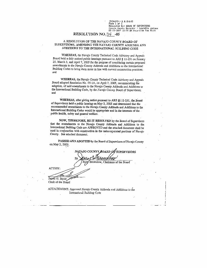

Table of Contents
Page
Area Offices ................................................................................................... 2
Adopted Codes ............................................................................................... 3
Issuance of Permit .......................................................................................... 3
Design Criteria ............................................................................................... 4
Permits Required ............................................................................................ 5
Required Inspections ...................................................................................... 5
Foundations, Piers and Stem Walls ................................................... 6 thru10
Floors ............................................................................................................ 11
Roofs ............................................................................................................ 11
Framing ........................................................................................................ 11
Electrical ...................................................................................................... 12
Plumbing ...................................................................................................... 12
Drywall ......................................................................................................... 13
Final Inspection ............................................................................................ 13
Illustrations .......................................................................................................
Typical Footings, Piers and Stem Walls ........................................... 7 thru 10
Furnace Installation Attic ............................................................................. 14
Furnace Installation Crawl Space ................................................................ 16
Drain Pan Guidelines ................................................................................... 17
Typical Deck and Porch ............................................................................... 18
Typical Room Addition ............................................................................... 19
Framing Terminology .................................................................................. 20
Span Tables ......................................................................................................
Girder and Header Spans for Exterior Walls ............................................... 21
Header Spans for Non-Bearing Walls ......................................................... 22
Joists and Rafters ......................................................................................... 22
1

Public Works/Planning & Zoning
Area Offices www.navajocountyaz.gov
Holbrook Area Navajo County
Holbrook Planning & Zoning
Woodruff P.O. Box 668
Joseph City 100 East Code Talkers Dr.
Sun Valley Holbrook, AZ 86025
Adamana 928 524-4100
Winslow 928 524-4122 (FAX)
Show Low Area Navajo County
Show Low Building & Safety
Pinetop 550 N. 9th
Place
Lakeside Show Low, AZ 85901
Linden 928-532-6040
Pinedale 928-532-6044 (FAX)
Concho
Taylor
Snowflake
Heber/Overgaard Area Navajo County
Clay Springs Building & Safety
Aripine P.O. Box 1212
Chevelon Retreat 2188 W. Country Club Dr.
928-535-7110 Overgaard, AZ 85933
928-535-7114 (FAX)
2
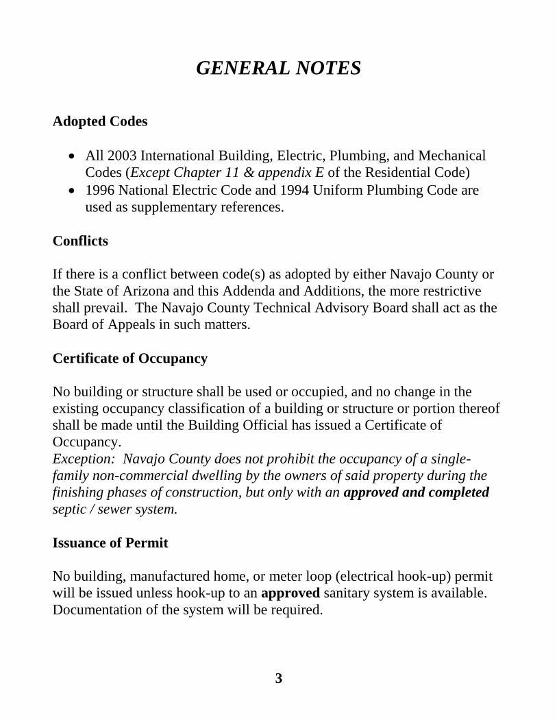
GENERAL NOTES
Adopted Codes
All 2003 International Building, Electric, Plumbing, and Mechanical
Codes (Except Chapter 11 & appendix E of the Residential Code)
1996 National Electric Code and 1994 Uniform Plumbing Code are
used as supplementary references.
Conflicts
If there is a conflict between code(s) as adopted by either Navajo County or
the State of Arizona and this Addenda and Additions, the more restrictive
shall prevail. The Navajo County Technical Advisory Board shall act as the
Board of Appeals in such matters.
Certificate of Occupancy
No building or structure shall be used or occupied, and no change in the
existing occupancy classification of a building or structure or portion thereof
shall be made until the Building Official has issued a Certificate of
Occupancy.
Exception: Navajo County does not prohibit the occupancy of a single-
family non-commercial dwelling by the owners of said property during the
finishing phases of construction, but only with an approved and completed
septic / sewer system.
Issuance of Permit
No building, manufactured home, or meter loop (electrical hook-up) permit
will be issued unless hook-up to an approved sanitary system is available.
Documentation of the system will be required.
3

Design Criteria
Engineering
Any Structure built for commercial use as well as any steel, log or post and
beam type construction, shall be approved and stamped by an architect or
engineer registered in the State of Arizona. This policy is at the discretion of
the Technical Advisory Board and the Board of Supervisors.
DESIGN LOADS
Area Wind/Exposure Seismic Roof Pitch Snow Load PSF
Heber/Overgaard 80 mph / B 0:12 up to 4:12 45 PSF
Pinetop/Lakeside 80 mph / B B 4:12 or greater 40 PSF
Show Low 80 mph / B
Clay Springs 80 mph / C 0:12 up to 4:12 35 PSF
Pinedale 80 mph / B B 4:12 or greater 30 PSF
Snowflake/Taylor 80 mph / C
Shumway 80 mph / B
Holbrook 80 mph / C 0:12 up to 4:12 25 PSF
Joseph City 80 mph / C B 4:12 or greater 20 PSF
Winslow 80 mph / C
Woodruff 80 mph / C
Note: All Signs to be designed for a load of 100 mph.
All Greenhouses designed for 100 PSF live load.
4

Permits Required IBC 105.1
Any owner or authorized agent who intends to construct, alter, move, enlarge or
change the occupancy of a building or structure shall first make application and
obtain the required permit.
Work Exempt From Permit IBC 105.2
1. One story detached(a) accessory structures, provided the floor area does not
exceed 144 square feet.
2. Fences not over 6 feet high.
3. Retaining walls not over 4 feet in height measured from the bottom of the
footing to the top of the wall.
4. Flat work, sidewalks and driveways if not more than 30 inches above adjacent
grade and not above any basement or story below.
5. Replacement of roof coverings or exterior siding.
6. Interior remodeling not exceeding $1000.00 in materials & labor (a) Detached generally means a required 15 ft separation between structure, see the specific zoning
requirements for you project.
Required Inspections
1. Septic systems.
2. Footing steel
3. Stem steel
4. Under-slab copper, sewer, electrical.
5. Under-floor framing…BEFORE FLOOR SHEETING.
6. Roof sheathing & Shear panel nail-off.
7. Rough-in Framing, Electrical, Plumbing, Venting and Heating. (House must be weather-sealed prior to rough-in inspections)
8. Drywall nailing.
9. Final Inspection.
10. Additional inspections may be required for specialized projects.
All inspections must be performed and work approved before issuance of a
Certificate of Occupancy.
5
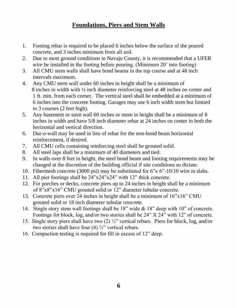
Foundations, Piers and Stem Walls
1. Footing rebar is required to be placed 6 inches below the surface of the poured
concrete, and 3 inches minimum from all soil.
2. Due to most ground conditions in Navajo County, it is recommended that a UFER
wire be installed in the footing before pouring. (Minimum 20’ into footing)
3. All CMU stem walls shall have bond beams in the top course and at 48 inch
intervals maximum.
4. Any CMU stem wall under 60 inches in height shall be a minimum of
8 inches in width with ½ inch diameter reinforcing steel at 48 inches on center and
1 ft. min. from each corner. The vertical steel shall be embedded at a minimum of
6 inches into the concrete footing. Garages may use 6 inch width stem but limited
to 3 courses (2 feet high).
5. Any basement or stem wall 60 inches or more in height shall be a minimum of 8
inches in width and have 5/8 inch diameter rebar at 24 inches on center in both the
horizontal and vertical direction.
6. Dur-o-wall may be used in lieu of rebar for the non-bond beam horizontal
reinforcement, if desired.
7. All CMU cells containing reinforcing steel shall be grouted solid.
8. All steel laps shall be a minimum of 40 diameters and tied.
9. In walls over 8 feet in height, the steel bond beam and footing requirements may be
changed at the discretion of the building official if site conditions so dictate.
10. Fibermesh concrete (3000 psi) may be substituted for 6”x 6”-10/10 wire in slabs.
11. All pier footings shall be 24”x24”x24” with 12” thick concrete.
12. For porches or decks, concrete piers up to 24 inches in height shall be a minimum
of 8”x8”x16” CMU grouted solid or 12” diameter tubular concrete.
13. Concrete piers over 24 inches in height shall be a minimum of 16”x16” CMU
grouted solid or 18 inch diameter tubular concrete.
14. Single story stem wall footings shall be 18” wide & 18” deep with 10” of concrete.
Footings for block, log, and/or two stories shall be 24” X 24” with 12” of concrete.
15. Single story piers shall have two (2) ½” vertical rebars. Piers for block, log, and/or
two stories shall have four (4) ½” vertical rebars.
16. Compaction testing is required for fill in excess of 12” deep.
6


Floors
1. All under-slab plumbing, electrical and mechanical shall be inspected and approved
before placement of concrete.
2. Wood floor framing shall be inspected and approved before placement of sheathing.
(Minimum ¾” T. & G.)
3. All bearing points of girders must be strapped by approved means.
Roofs
1. Roof sheathing nail spacing (6” on edges & 12 “ in fields) shall be inspected and
approved before placement of roofing material.
2. Trusses shall be engineered and manufactured for all imposed loads including any
mechanical equipment or concrete roofing etc..
3. Roof sheathing face grain shall be at right angles to rafters with the following ratios:
5/8” sheathing : rafters at 24” O.C. 3/4" sheathing : rafters at 32” O.C. 1/2”
sheathing may be used only on unattached accessory buildings with rafters at 16”
O.C.
Framing
1. All headers to be box or double 2x material on edge. Flat or “California” type
headers
are not allowed.
2. All walls shall have double top plates (48” Minimum Overlap).
3. Metal hurricane straps (e.g. H2.5s) must be secured at each end of each rafter to the
double top plates of walls.
4. All 2x4 framed walls, 16 inch on center maximum.
5. End wall ladder backing is not allowed.
6. Ceiling height in livable areas shall be a minimum of 7 ft 6 inches with the exception
of bathrooms, kitchens and hallways which may be reduced to 7 feet.
7. All walls shall be braced for shear.
8. Engineering calculations and design data may be required for any unusual design, at
the discretion of the building official, prior to issuance of a building permit.
9. Attic access openings must be 30 “ x 22 “ minimum.
11

Electrical
1. Inspections based on 2003 I.E.C. and referenced with 1996 National Electric Code.
2. All receptacle wiring shall be 12 AWG minimum on 20 Amp circuit.
3. Separate lighting circuits may use 14 AWG with 15 Amp breakers.
4. Bathrooms must be on their own separate circuit.
5. Ground Fault Circuit Interrupters are required for:
a. All receptacles in bathrooms
b. All receptacles within 6 feet of water
c. All countertop receptacles
d. All exterior receptacles (Must have weather-proof cover)
e. All receptacles in garages and unfinished basements
f. All temporary receptacles.
g. All circuits providing power to spas or hot tubs and any convenience
outlet within 10 feet of unit.
Plumbing
1. Inspections based on 2003 I.P.C. and referenced with 1994 Uniform Plumbing Code.
2. All venting through the roof shall be a minimum of 2” in diameter.
3. LPG service, facilities, supply, or storage shall not be installed in a
basement, pit, or crawlspace.
4. All fireplaces supplied with gas log lighters shall have a key type gas valve
installed outside the hearth and within three feet of the device.
5. No atmospheric valve type venting (e.g. Studor brand vents) will be allowed without
prior approval from the Building Official. (Attic placement prohibited)
Drywall
1. Green board shall not be installed on ceilings.
2. Sheetrock shall not be installed on the exterior of any structure.
3. ATTACHED GARAGES: All ceilings and walls common with a dwelling,
shall be 5/8’ type X sheetrock minimum. (Solid core doors with self closing
hinges are required at the dwelling access.)
4. Fastener spacing: Ceilings = 6” on edges 8” in fields
Walls = 7” on edges 12” in fields
12

FINAL INSPECTION CHECKLIST
1. Septic and plumbing in total working order.
2. Concrete approach pads, guard and hand rails at correct heights & spacings.
3. Electric panels labeled, and outlets closed up and properly working.
4. GFCIs and inter-connected smoke detectors installed where required.
5. Furnace and water heater rooms vented with self closing doors as required for gas.
T&P valves plumbed to outside.
6. Solid core, self closing door from garage to dwelling.
7. No obstructions in stem wall or attic access openings.
8. Yard landscaped for proper water drainage.
9. Spark arrester installed and chimney capped.
10. Garage door operable
11. No under-floor L.P.G. units
12. Proper fall on sewer lines & no debris in crawlspace
13. Culvert installed (if required).
14. Additional inspections may be required as site conditions dictate.
15. A Temporary Certificate of Occupancy may be issued for a single family dwelling
(with a completed and approved sanitary system) contingent upon corrections
and/or completion within 60 days from the date of this inspection.
13


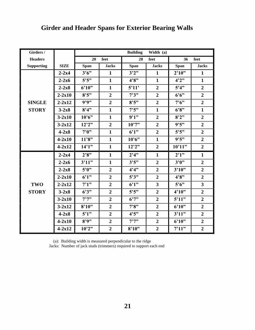
Girder and Header Spans for Exterior Bearing Walls
Girders /
SIZE
Building Width (a)
Headers 20 feet 28 feet 36 feet
Supporting Span Jacks Span Jacks Span Jacks
2-2x4 3’6” 1 3’2” 1 2’10” 1
2-2x6 5’5” 1 4’8” 1 4’2” 1
2-2x8 6’10” 1 5’11’ 2 5’4” 2
2-2x10 8’5” 2 7’3” 2 6’6” 2
SINGLE 2-2x12 9’9” 2 8’5” 2 7’6” 2
STORY 3-2x8 8’4” 1 7’5” 1 6’8” 1
3-2x10 10’6” 1 9’1” 2 8’2” 2
3-2x12 12’2” 2 10’7” 2 9’5” 2
4-2x8 7’0” 1 6’1” 2 5’5” 2
4-2x10 11’8” 1 10’6” 1 9’5” 2
4-2x12 14’1” 1 12’2” 2 10’11” 2
2-2x4 2’8” 1 2’4” 1 2’1” 1
2-2x6 3’11” 1 3’5” 2 3’0” 2
2-2x8 5’0” 2 4’4” 2 3’10” 2
2-2x10 6’1” 2 5’3” 2 4’8” 2
TWO 2-2x12 7’1” 2 6’1” 3 5’6” 3
STORY 3-2x8 6’3” 2 5’5” 2 4’10” 2
3-2x10 7’7” 2 6’7” 2 5’11” 2
3-2x12 8’10” 2 7’8” 2 6’10” 2
4-2x8 5’1” 2 4’5” 2 3’11” 2
4-2x10 8’9” 2 7’7” 2 6’10” 2
4-2x12 10’2” 2 8’10” 2 7’11” 2
(a): Building width is measured perpendicular to the ridge
Jacks: Number of jack studs (trimmers) required to support each end
21

HEADER SPANS FOR INTERIOR NON-BEARING WALLS
SIZE MAXIMUM SPAN
4x4 or 2-2x4 3’
4x6 or 2-2x6 6’
4x8 or 2-2x8 8’
4x10 or 2-2x10 10’
4x12 or 2-2x12 12’
Note: All lumber to be placed on edge
ALLOWABLE SPANS FOR JOISTS AND RAFTERS
LL=40 DL=10 LL=40 DL=15 LL=45 DL=15
Lumber
Sizes
Floor Joists
No Drywall
Below
1*
Floor Joists
Drywall
Below
Ceiling Joists
With Drywall
Rafters
0:12 up to
4:12 Pitch
2*
Rafters
4:12 Pitch
or More
2*
2x4 @ 12” O.C. 9’8”
2x4 @ 16” O.C. 8’3”
2x4 @ 24” O.C. 7’8”
2x6 @ 12” O.C. 10’8” 9’9” 15’2” 11’2” 12’0”
2x6 @ 16” O.C. 9’6” 8’10” 13’9” 9’9” 10’8”
2x6 @ 24” O.C. 8’4” 7’8” 12’0” 7’11” 8’8”
2x8 @ 12” O.C. 13’10” 12’10” 19’11” 14’10” 16’0”
2x8 @ 16” O.C. 12’8” 11’8” 18’1” 12’10” 14’8”
2x8 @ 24” O.C. 10’3” 10’2” 15’10” 10’6” 11’6”
2x10 @12” O.C. 17’8” 16’5” 25’5” 18’11” 20’0”
2x10 @16” O.C. 16’0” 14’11” 21’9” 16’4” 17’7”
2x10 @24” O.C. 12’9” 12’3” 20’2” 13’4” 14’8”
2x12 @12” O.C. 21’6” 19’11” 23’0” 24’6”
2x12 @16” O.C. 18’6” 17’9” 19’11” 21’8”
2x12 @24” O.C. 15’0” 14’4” 16’3” 17’9”
Notes: Joists calculated @ LL deflection = 360, DL deflection = 240 with ¾” Min. Sheathing
All spans based on Douglas Fir Lumber: 1* = #1 or Better 2* = Select Structural
Reduce spans by 10% if Pine Lumber is used.
22