Embed Size (px)
Citation preview

Specifications subject to change without notice. 443 06 1503 00 Dec. 2010
NAHA00801LP or PART NO. 1183388
INSTALLATION INSTRUCTIONSNATURAL TO PROPANE CONVERSION KIT
NOTE: Read the entire instruction manual before startingthe installation.
SAFETY CONSIDERATIONSInstalling and servicing heating equipment can behazardous due to gas and electrical components. Onlytrained and qualified personnel should install, repair, orservice heating equipment.Untrained personnel can perform basic maintenancefunctions, such as cleaning and replacing air filters.Trained service personnel must perform all otheroperations. When working on heating equipment, observeprecautions in the literature, on tags, and on labelsattached to or shipped with the unit, and other safetyprecautions that may apply.Follow all safety codes. In the United States, follow allsafety codes including the National Fuel Gas Code(NFGC) NFPA 54−2009/ANSI Z223.1−2009.Wear safety glasses and work gloves. Have a fireextinguisher available during start−up, adjustment Steps,and service calls.Recognize safety information. This is the safety−alertsymbol . When you see this symbol on the furnace andin instructions or manuals, be alert to the potential forpersonal injury.Understand the signal words DANGER, WARNING, andCAUTION. These words are used with the safety−alertsymbol. DANGER identifies the most serious hazardswhich will result in severe personal injury or death.WARNING signifies a hazard which could result inpersonal injury or death. CAUTION is used to identifyunsafe practices which may result in minor personal injuryor product and property damage. NOTE is used tohighlight suggestions which will result in enhancedinstallation, reliability, or operation.
TABLE OF CONTENTSSafety Considerations 1. . . . . . . . . . . . . . . . . . . . . . . . . . .Introduction 1. . . . . . . . . . . . . . . . . . . . . . . . . . . . . . . . . . . .Description and Usage 1. . . . . . . . . . . . . . . . . . . . . . . . . .Installation Induced−Combustion, Single−stage, Non−Condensing 2. . . . . . . . . . . . . . . . . . . . . . . . . . . . .ECM Single Stage Control 5. . . . . . . . . . . . . . . . . . . . . . .Installation Induced−Combustion, Two−Stage, and Variable Speed 8. . . . . . . . . . . . . . . . . . . . . . . . . . .Furnace Control for Two−Stage Non−Condensing Furnaces 12. . . . . . . . . . . . . . . . . . . .Furnace Control for Variable Speed Non−Condensing Furnaces 12. . . . . . . . . . . . . . . . . . . .
FIRE, EXPLOSION, ELECTRICAL SHOCK, ANDCARBON MONOXIDE POISONING HAZARD
Failure to follow this warning could result in personalinjury or death.
This conversion kit shall be installed by a qualifiedservice agency in accordance with the manufacturer’sinstructions and all applicable codes andrequirements of the authority having jurisdiction. If theinformation in these instructions is not followedexactly, a fire, explosion, or production of carbonmonoxide could result causing property damage,personal injury, or loss of life. The qualified serviceagency is responsible for the proper installation of thisfurnace with this kit. The installation is not proper andcomplete until the operation of the convertedappliance is checked as specified in themanufacturer’s instructions supplied with the kit.
! WARNING
INTRODUCTIONThese instructions cover the installation of gas conversionkit to convert the following furnaces from natural gas usageto propane gas usage. See appropriate section for yourfurnace type.NOTE: For use on 33.3 inch (846mm), multipoise,non−condensing furnace to convert from natural gas topropane gas.Section 1 Models: N8MSN, N8MSL, F8MXN, G8MXN,F8MXL and G8MXL 33.3−Inch High, Induced−Combustion, Hot−Surface Ignition, Single Stage,Non−Condensing 4−Way Multipoise Furnaces with 42,000through 154,000 Btuh gas input rates.Section 2 Models: F8MVL, G8MVL, F8MTL and G8MTL,33.3−Inch High, Induced−Combustion, Hot−SurfaceIgnition, Two−Stage and Variable−Speed,Non−Condensing Furnaces. This kit is designed for use infurnaces with 42,000 through 132,000 Btuh gas inputrates.
FIRE, EXPLOSION, ELECTRICAL SHOCKHAZARD
Failure to follow this warning could result in personalinjury, death or property damage.
Gas supply MUST be shut off before disconnectingelectrical power and proceeding with conversion.
! WARNING
DESCRIPTION AND USAGEThis kit is designed for use in the furnaces listed above.See Table 1 for kit contents. To accommodate manydifferent furnace models, more parts are shipped in kit thanwill be needed to complete conversion. When installation iscomplete, discard extra parts.

2 443 06 1503 00Specifications subject to change without notice.
Table 1 – Kit Contents
DESCRIPTION QTY
Main Burner Orifice(Drill Size 1.30 mm)
7
Main Burner Orifice(Drill Size 1.25 mm)
7
Main Burner Orifice(Drill Size No. 55)
7
Main Burner Orifice(Drill Size No. 56)
7
Screw, Spoiler Size No. 4 7
Low Gas Pressure Switch (Propane)(LGPS)
1
Nipple Size 1/8 MPT 1
90° Street Elbow (1/8 in. / 3 mm) 1
Male X Female X Female Tee(1/8 in. / 3 mm)
1
Splice Connector(1/4 in. Male, Both Ends)
1
Splice Connector(3/16 in. Male, Both Ends)
1
Orange Wire Assembly (18 in. / 457 mm) 2
Orange Wire Assembly (12 in. / 305 mm) 1
Yellow Wire Assembly (6 in. / 152 mm) 1
Yellow Wire Assembly (14 in. / 356 mm) 1
Yellow Wire Assembly (16 in. / 406 mm) 1
Wire Tie 1
337057-201 Conversion Rating PlateLabel—Non-Condensing Furnaces
1
337057-204 ConversionRating Plate Label—Non-Condensing
Furnaces1
337057-205 Conversion ResponsibilityLabel
1
337057-202 Gas Control Conversion Label (adjusted)
1
337057-203 Gas Control Conversion Label (converted)
1
Installation Instructions 1
Regulator Spring Kit (White—Propane-EF39ZW023) for White-Rodgers36C,36E, 36F, 36G and 36J Valve
2
Drill Bit Size 5/64” 1
INSTALLATIONSECTION 1
INDUCED−COMBUSTION,HOT−SURFACE IGNITION,
SINGLE−STAGE, 33.3−INCH (846 MM)HIGH, NON−CONDENSING FURNACES
SINGLE STAGE FURNACES
N8MSN F8MXN G8MXN
N8MSL F8MXL G8MXL
Step 1 — Install Main Burner Orifices and BurnerSpoiler Screws
UNIT DAMAGE HAZARD
Failure to follow this caution may result in unitdamage.
DO NOT re−drill burner orifices. Improper drilling mayresult in burrs, out−of−round holes, etc. Obtain neworifices if orifice size must be changed. (See Figure 1)
CAUTION!
NOTE: See Figure 2 for component location in UPFLOWorientation. Reorient component arrangement whenfurnace is installed in other positions.
Figure 1 − Burner Orifice
BURNER ORIFICE BURNER
ORIFICE
A96249
1. Turn off furnace gas and electrical supplies.2. Remove outer door.3. Turn furnace gas valve switch to OFF position.4. If furnace is oriented in a manner that the vent
connector interferes with burner removal, removevent connector from vent elbow inside the furnace.Support the remaining vent connector withtemporary metal wire or straps to prevent damage tothe remaining portions of the vent connector.
5. Remove gas supply pipe from gas valve (ifinstalled).
6. Disconnect wires from gas valve7. Remove the two (2) screws on the left side that
secure the manifold to the burner box.8. Swing out manifold from burners then pull manifold
out of right side of burner box. (See Figure 2)9. Remove and discard orifices from manifold.
10. Refer to conversion kit rating plate 337057−204 todetermine main burner orifice size. (See Figure 13)
UNIT OPERATION HAZARD
Failure to follow this caution may result in unitdamage or improper operation.
Label all wires prior to disconnection when servicingcontrols.
CAUTION!
Gas input rate on furnace rating plate is for installations ataltitudes up to 2000 ft. (609 M).In the U.S.A., the input rating for altitudes above 2000 ft.(609 M) must be reduced by 4 percent for each 1000 ft.(305 M) above sea level.The Conversion Kit Rating Plate accounts for high altitudederate.
11. Install main burner orifices. Do not use Teflon tape.Finger−tighten orifices at least one full turn toprevent cross−threading, then tighten with wrench.There are enough orifices in each kit for largestfurnace. Discard extra orifices.
12. To install burner spoiler screws, follow these steps:a. Disconnect Hot Surface Igniter (HSI) wires from
HSI.b. Disconnect Flame Sensor wire from Flame Sensor.c. Slide one−piece burner assembly out of slots on
sides of burner box.d. Remove the Hot Surface Igniter (HSI) and bracket
from the burner assembly.e. Remove the flame sensor from the burner
assembly.f. Locate the dimple on each burner venturi tube
(Figure 3).

3443 06 1503 00 Specifications subject to change without notice.
g. Drill a 5/64−in. (2 mm) hole (supplied in kit) in eachdimple.
h. Install a spoiler screw in each drilled hole drilling asstraight as possible
Figure 2 − Component Location
INDUCER MOTORASSEMBLY
PRESSURESWITCH
FLUE COLLECTORBOX
GAS VALVE
HOT SURFACEIGNITOR
BLOWERDOOR SAFETY
SWITCH
FURNACECONTROL
BOARD
VENTELBOW
MAIN LIMITSWITCH (BEHINDGAS VALVE)
BLOCKED VENTSWITCH
FLAMESENSOR
GAS MANIFOLD
GAS BURNER
BLOWER ANDMOTOR
MANUAL RESETLIMIT SWITCHES
CAPACITOR/POWER CHOKE
RATING PLATE NOT SHOWN(LOCATED ON BLOWER DOOR)
Figure 3 − Location of Dimple for Spoiler Screw
A06432
NOTE: Models N8MSL, F8MXL, and G8MXL are suppliedwith NOx emissions−reduction devices necessary for usewith Natural Gas in NOx emissions−regulated areas.
UNIT DAMAGE HAZARD
Failure to follow this caution may result in unitdamage.
Furnace models N8MSL, F8MXL, and G8MXL MUSThave low NOx devices removed prior to operatingfurnace on propane gas.
CAUTION!
13. For NOx device removal, follow these additionalsteps:a. Remove the screw underneath the heat exchanger
inlet that secures the NOx device in the heatexchanger. (See Figure 4)
b. Use a pair of needle nose pliers to remove the NOxdevice. Squeeze the sides of the device, ifnecessary, to remove from the heat exchanger.
Figure 4 − NOx Device Location
A02195
Figure 5 − Igniter to Burner
A05025
c. Re−install screw in hole underneath heatexchanger inlet.
NOTE: It is very IMPORTANT to reinstall the NOx bracketmounting screw.
d. Repeat steps a thru c for each heat exchanger.14. To reinstall burner assembly:
a. Attach flame sensor to burner assembly.b. Install HSI and bracket to burner assembly.c. Insert one−piece burner in slot on sides of burner
box and slide burner back in place.d. Reattach HSI wires to HSI. Verify igniter to burner
alignment. For Silicon Nitride igniters, see Figure 5and Figure 6.
e. Re−attach Flame sensor wire to Flame Sensor.15. Reinstall manifold by inserting right end of manifold
into opening in right side of burner box.16. Swing manifold into burner assembly and insert
orifices into openings on burners.17. Verify that orifices are fully inserted into burners and
burners are fully seated in burner box.

4 443 06 1503 00Specifications subject to change without notice.
Figure 6 − Igniter to Burner
1-7/8(47.6 mm)
A05026
Figure 7 − Igniter to Burner
A93347
18. Secure manifold to left side of burner box, verifyingthat green ground wire is reattached to burner box.
19. Reconnect wires to gas valve per the wiring diagramsupplied with the unit.
NOTE: Failure to attach ground wire to gas manifold onburner box will result in loss of flame signal resulting in ano heat condition.
NOTE: Use propane−gas resistant pipe dope to preventgas leaks. DO NOT use Teflon tape.
Step 2 — Convert Single−Stage Gas ValveNOTE: The following furnaces must have the regulatorspring replaced in the gas valve:
SINGLE STAGE FURNACES
N8MSN F8MXN G8MXN
N8MSL F8MXL G8MXL
1. Be sure main gas and electrical supplies are off.2. Remove regulator seal cap. (Figure 10)3. Remove adjustment screw and natural gas regulator
spring (silver).
4. Install propane gas regulator spring (white) in gasvalve.
5. Turn regulator adjustment screw clockwise (in) 8.5turns for Figure 8. Go to Step 3
NOTE: DO NOT reinstall regulator seal cap at this time.Figure 8 − Single Stage Gas Valve Series G / J
REGULATOR SEAL CAP
REGULATORADJUSTMENTSCREW
REGULATOR SPRING(PROPANE - WHITE, 8.5 TURNSNATURAL - SILVER, 8.5 TURNS)
GAS PRESSURE REGULATOR ADJUSTMENT
MANIFOLD PRESSURE TAP
INLET PRESSURE TAP
ON/OFF SWITCH
A07017
Figure 9 − Gas Valve Inlet Pressure Tap
1/8" brass male coupling
1/8" brass female x female xmale tee for installing LGPS
A05155
Figure 10 − LGPS Installed
Manometerconnection
A05191
Step 3 — Install Low Gas Pressure Switch (LGPS)NOTE: The inlet gas pipe must be disconnected fromvalve so pressure switch can be installed.
NOTE: Use propane−gas−resistant pipe dope on allconnections to prevent gas leaks. DO NOT use Teflontape.
1. Be sure main gas and electric supplies to furnaceare off.
5443 06 1503 00 Specifications subject to change without notice.
2. Remove 1/8−in. (3 mm) pipe plug from inlet pressuretap on gas valve. (See Figure 8) DO NOT DISCARD1/8−in. (3 mm) PLUG.
3. Apply pipe dope sparingly to one end of 1/8−in. (3mm) brass male coupling (provided in kit) and installthe doped end in 1/8−in. (3 mm) tapped opening ingas valve inlet pressure−tap. Tighten fitting with asmall open−end wrench. (See Figure 9)
4. Apply pipe dope sparingly to opposite end of the1/8−in. (3 mm) brass coupling (provided in kit).Install the female end of the female x female x maletee on the brass coupling. Tighten coupling fingertight. Use a small open−end wrench for finaltightening. (See Figure 9)
5. Apply pipe dope sparingly to male end of brass tee.Install propane low gas pressure switch (provided inkit) on male end of the female x female x male tee.Tighten switch finger tight. Use a small open−endwrench on base of pressure switch for finaltightening. (See Figure 10)
6. Connect a manometer to the open end of the teeinstalled in the gas valve. (See Figure 9 andFigure 10)
7. Apply pipe dope sparingly to end of inlet gas pipeand reconnect pipe to gas valve.
Step 4 — Check Inlet Gas PressureNOTE: This kit is to be used only when inlet gas pressureis between 11.5−in. w.c. and 13.6−in. w.c.
1. Verify manometer is connected to the brass teeconnected to the inlet pressure tap on gas valve.(See Figure 9 or Figure 10)
UNIT DAMAGE HAZARD
Failure to follow this caution may result in unitdamage.
DO NOT operate furnace more than one minute tocheck inlet gas pressure, as conversion is notcomplete at this time.
CAUTION!
2. Turn on furnace power supply.3. Turn gas supply manual shutoff valve to ON
position.4. Turn furnace gas valve switch to ON position.5. Jumper R−W thermostat connections on the Single
Stage furnace control (see Figure 11).6. When main burners ignite, confirm inlet gas
pressure is between 11.5−in. w.c. and 13.6−in. w.c.7. Remove jumper across thermostat connections to
terminate call for heat.8. Turn furnace gas valve switch to OFF position.9. Turn gas supply manual shutoff valve to OFF
position.10. Turn off furnace power supply.11. Remove manometer.12. Apply pipe dope sparingly to end of inlet gas pipe
plug and install into unused end of 1/8−in. (3 mm)tee. Use a small back−up wrench on tee whentightening gas inlet pipe plug. (See Figure 9 orFigure 10)
Figure 11 − ECM Single Stage Control
ÏÏÏÏÏÏÏÏÏÏÏÏ
TWINNING AND/ORCOMPONENT TEST
TERMINAL
PL1 − LOW VOLTAGEMAIN HARNESSCONNECTOR
TRANSFORMER 24VACCONNECTIONS
EAC−1 TERMINAL(115 VAC 1.0 AMPMAX.)
COOL
SPARE−2
SPARE−1
COM/BLUE
115−VAC (L2)NEUTRALCONNEC-TIONS
24−V THERMOSTATTERMINALS
HUMIDIFIER TERMINAL(24−VAC 0.5 AMP MAX)
3−AMPFUSE
LED OPERATION& DIAGNOSTICLIGHT
24VAC/RED
BLOWERSPEEDSELECTIONTERMINALS
BL−1 XFMR
HUMIDIFIERTERMINAL115−VAC
COM
HEAT
COOL
FAN
SPARE 2 SPARE 1
Y1
DH
UM
HEAT OFF−DELAY
120 180
90 150
ÏÏÏÏÏÏÏÏ
ÏÏÏÏ
EAC −2
24V M
TR
TAP
S
L2
115 VAC (L1)NEUTRAL CON-NECTIONS
L1 IND
PL2−HOT SURFACE IGNITOR (HSI) &INDUCER MOTOR (IND) CONNECTORHUMIDIFIER TERMINAL
HEAT
FAN

6 443 06 1503 00Specifications subject to change without notice.
Step 5 — Modify Single Stage Pressure SwitchWiringRefer to furnace wiring diagram (located inside unit).
1. Disconnect yellow wire from the N.O. contact of thepressure switch PRS and connect it to the N.O.terminal on the low gas pressure switch (LGPS).
2. Connect the insulated straight terminal of the 16−in(406 mm) yellow wire (provided in kit) to the Cterminal on the low gas pressure switch (LGPS).
3. Connect insulated flag terminal of 16−in (406 mm)yellow wire to the N.O. terminal to pressure switchPRS.
4. Route yellow wires along wire harness. Secure withwire tie provided in kit. Go to Step 6.
Step 6 — Check Furnace Operation and MakeNecessary Adjustments
1. Be sure main gas and electric supplies to furnaceare off.
2. Remove 1/8−in. (3 mm) pipe plug from manifoldpressure tap on downstream side of gas valve. (SeeFigure 8)
3. Attach manometer to manifold pressure tap on gasvalve.
NOTE: The 1/8−in. (3 mm) NPT street elbow included inthe kit may be attached to the gas valve manifold pressuretap or a field supplied 90� 1/8−in. (3 mm) NPT barbedfitting may be used to simplify manometer connection togas valve when vent connector passes inside furnacecasing. (See Figure 13) The street elbow may be left inplace on gas valve when plug from manifold pressure tapis installed in street elbow.
4. Turn gas supply manual shutoff valve to ONposition.
5. Turn furnace gas valve switch to ON position.6. Check all threaded pipe connections for gas leaks.7. Turn on furnace power supply.
Figure 12 − Plug Removed from Gas ValveStreet Ell Installed and Plug Reinstalled in Ell
A02197
FIRE AND EXPLOSION HAZARD
Failure to follow this warning could result in personalinjury and/or death.
NEVER test for gas leaks with an open flame. Use acommercially available soap solution made specificallyfor the detection of leaks to check all connections.
! WARNING
Step 7 — Gas Input Rate InformationThe gas−input rate for propane is the same as for naturalgas. See furnace rating plate for input rate. The input ratefor propane is determined by manifold pressure and orificesize.Gas input rate on furnace rating plate is for installations ataltitudes up to 2000 ft. (609 M).In the U.S.A., the input rating for altitudes above 2000 ft.(609 M) must be reduced by 4 percent for each 1000 ft.(305 M) above sea level.The Conversion Kit Rating Plate accounts for high altitudederate.
Figure 13 − Conversion Kit Rating Plate − 337057−201
Step 8 — Set Gas Input Rate1. Jumper R and W thermostat connections to call for
heat. (See Figure 11)2. Check manifold orifices for gas leaks when main
burners ignite.3. Adjust gas manifold pressure. (Refer to conversion
kit rating plate 337057−201).a. Turn adjusting screw counterclockwise (outwards)
to decrease manifold pressure or clockwise(inwards) to increase manifold pressure. (Figure 8)
NOTE: Gas valve regulator seal cap MUST be in placewhen checking input rate.
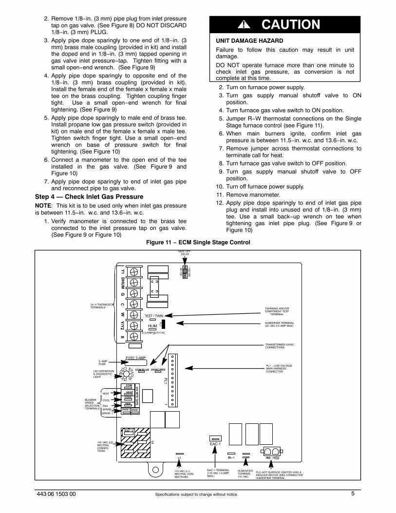
b. When correct input is obtained, main burner flameshould be clear blue, almost transparent. (SeeFigure 14) Be sure regulator seal cap is in placewhen finished.
4. Remove jumper across R and W thermostatconnections to terminate call for heat.
5. Turn furnace gas valve control switch or controlknob to OFF position.
7443 06 1503 00 Specifications subject to change without notice.
6. Turn off furnace power supply.7. Remove manometer and replace manifold pressure
tap plug. (See Figure 8)NOTE: Use propane−gas−resistant pipe dope to preventgas leaks. DO NOT use Teflon tape.
8. Turn furnace gas valve control switch or controlknob to ON position.
9. Turn on furnace power supply.10. Set room thermostat to call for heat.11. Check manifold pressure tap plug for gas leaks
when main burners ignite.12. Observe unit operation through two complete
heating cycles. See Sequence of Operation infurnace Installation, Start−up and OperatingInstructions.
13. Set room thermostat to desired temperature.
Step 9 — Check Low Gas Pressure SwitchOperationThe newly installed low gas pressure switch is a safetydevice used to guard against adverse burner operatingcharacteristics that can result from low gas supplypressure. Switch opens at not less than 6.5 in. w.c. andcloses at not greater than 10.2 in. w.c.This switch also prevents operation when the propane tanklevel is low which can result in gas with a highconcentration of impurities, additives, and residues thathave settled to the bottom of the tank. Operation underthese conditions can cause harm to the heat exchangersystem.This normally open switch closes when gas is supplied togas valve under normal operating pressure. The closedswitch completes control circuit. Should an interruption orreduction in gas supply occur, the gas pressure at switchdrops below low gas pressure switch setting, and switchopens. Any interruption in control circuit (in which low gaspressure switch is wired) quickly closes gas valve andstops gas flow to burners.When normal gas pressure is restored, the system mustbe electrically reset to re−establish normal heatingoperation.Before leaving installation, observe unit operation throughtwo (2) complete heating cycles. During this time, turn gas
supply to gas valve off just long enough to completelyextinguish burner flame, then instantly restore full gassupply. To ensure proper low gas pressure switchoperation, observe that there is no gas supply to burnersuntil after hot surface igniter begins glowing.
Figure 14 − Burner Flame
����BURNER FLAME
BURNER
MANIFOLD
A89020
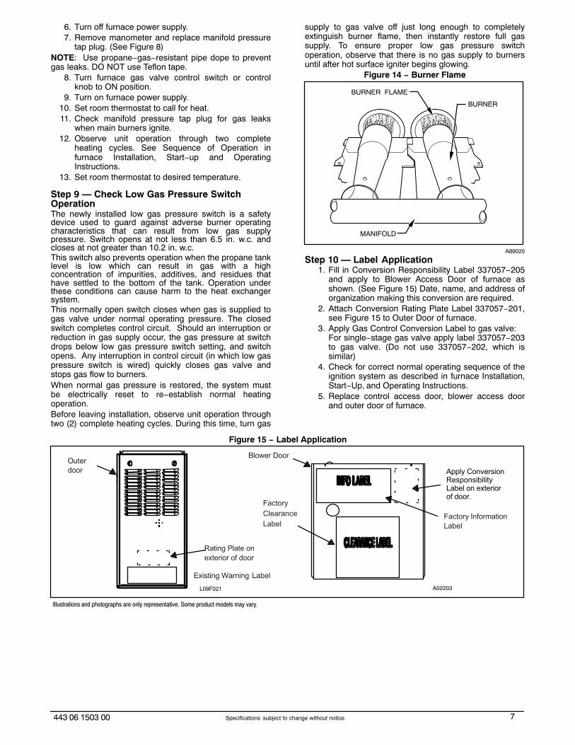
Step 10 — Label Application1. Fill in Conversion Responsibility Label 337057−205
and apply to Blower Access Door of furnace asshown. (See Figure 15) Date, name, and address oforganization making this conversion are required.
2. Attach Conversion Rating Plate Label 337057−201,see Figure 15 to Outer Door of furnace.
3. Apply Gas Control Conversion Label to gas valve:For single−stage gas valve apply label 337057−203to gas valve. (Do not use 337057−202, which issimilar)
4. Check for correct normal operating sequence of theignition system as described in furnace Installation,Start−Up, and Operating Instructions.
5. Replace control access door, blower access doorand outer door of furnace.
Figure 15 − Label Application
Factory
Clearance
LabelFactory Information
Label
Blower Door
Rating Plate on
exterior of door
Existing Warning Label
Od
uteroor
L09F021
Apply ConversionResponsibilityLabel on exteriorof door.
A02203
Illustrations and photographs are only representative. Some product models may vary.

8 443 06 1503 00Specifications subject to change without notice.
INSTALLATIONSECTION 2
INDUCED−COMBUSTION,HOT−SURFACE IGNITION, TWO−STAGE
AND VARIABLE SPEED, 33.3−IN.(846 MM) HIGH, NON−CONDENSING
FURNACES
Two-Stage Models Variable-Speed Models
F8MTL F8MVL
G8MTL G8MVL
Step 1 — Install Main Burner Orifices and BurnerSpoiler Screws
1. Turn off furnace gas and electrical supplies.2. Remove outer door.3. Turn furnace gas valve switch to OFF position.4. If furnace is oriented in a manner that the vent
connector interferes with burner removal, removevent connector from vent elbow inside the furnace.Support the remaining vent connector withtemporary metal wire or straps to prevent damage tothe remaining portions of the vent connector.
UNIT DAMAGE HAZARD
Failure to follow this caution may result in unitdamage.
DO NOT re−drill burner orifices. Improper drilling mayresult in burns, out−of−round holes, etc. Obtain neworifices if orifice size must be changed. (SeeFigure 16)
CAUTION!
BURNER ORIFICE BURNER
ORIFICE
A96249
Figure 16 − Burner OrificeNOTE: See Figure 17 for component location in upfloworientation. Re−orient component arrangement whenfurnace is installed in other positions.
5. Remove gas supply pipe from gas valve (ifinstalled).
6. Disconnect wires from gas valve.7. Remove the 2 screws on the left side that secure the
manifold to the burner box.8. Swing out manifold from burners then pull manifold
out of right side of burner box. (See Figure 17)
UNIT OPERATION HAZARD
Failure to follow this caution may result in unitdamage or improper operation.
Label all wires prior to disconnection when servicingcontrols.
CAUTION!
9. Remove and discard orifices from manifold.Gas input rate on furnace rating plate is for installations ataltitudes up to 2000 ft. (609 M).In the U.S.A., the input rating for altitudes above 2000 ft.(609 M) must be reduced by 4 percent for each 1000 ft.(305 M) above sea level.The Conversion Kit Rating Plate accounts for high altitudederate. See Figure 27.
Figure 17 − Component Location
INDUCER MOTORASSEMBLY
PRESSURESWITCHES
FLUE COLLECTORBOX
GAS VALVE
HOT SURFACEIGNITOR
BLOWER DOORSAFETY SWITCH
FURNACECONTROL
BOARD
VENTELBOW
MAIN LIMITSWITCH (BEHINDGAS VALVE)
BLOCKED VENTSWITCH
FLAMESENSOR
GAS MANIFOLD
GAS BURNER
BLOWER ANDMOTOR
MANUAL RESETLIMIT SWITCHES
CAPACITOR/POWER CHOKE
RATING PLATE NOT SHOWN(LOCATED ON BLOWER DOOR)
10. Install main burner orifices. Do not use Teflon tape.Finger−tighten orifices at least 1 full turn to preventcross−threading, then tighten with wrench. Thereare enough orifices in each kit for largest furnace.Discard extra orifices.
11. To install burner spoiler screws, follow these steps:a. Disconnect Hot Surface Igniter (HSI) wires from
HSI.b. Disconnect Flame Sensor wire from Flame Sensor.c. Slide one−piece burner assembly out of slots on
sides of burner box.d. Remove the Hot Surface Igniter (HSI) and bracket
from the burner assembly.e. Remove flame sensor from the burner assembly.f. Locate the dimple on each burner venturi tube (see
Figure 18).

9443 06 1503 00 Specifications subject to change without notice.
g. Drill a 5/64−in. (2 mm) hole (supplied in kit) in eachdimple.
h. Install a spoiler screw in each drilled hole drilling asstraight as possible.
Figure 18 − Location of Dimple for Spoiler Screw
A06432
NOTE: Models F8MTL, G8MTL, F8MVL and G8MVL aresupplied with NOx emissions−reduction devices necessaryfor use with Natural Gas in NOx emissions−regulatedareas.
UNIT DAMAGE HAZARD
Failure to follow this caution may result in unitdamage.
Furnace models F8MTL, G8MTL, F8MVL andG8MVL MUST have low NOx devices removed priorto operating furnace on propane gas.
CAUTION!
12. For NOx device removal, follow these additionalsteps:a. Remove the screw underneath the heat exchanger
inlet that secures the NOx device in the heatexchanger. (See Figure 19)
b. Use a pair of needle nose pliers to remove the NOxdevice. Squeeze the sides of the device, ifnecessary, to remove from the heat exchanger.
c. Re−install screw in hole underneath heatexchanger inlet.
Figure 19 − NOx Device Location
A02195
NOTE: It is very IMPORTANT to re−install the NOxbracket mounting screw.
d. Repeat steps a thru c for each heat exchanger.13. To reinstall burner assembly:
a. Attach flame sensor to burner assembly.Figure 20 − Igniter to Burner
A05025
Figure 21 − Igniter to Burner
1-7/8”47.6 mm
A05026
Figure 22 − Igniter to Burner
A93347
b. Install HSI and bracket to burner assembly.c. Insert one−piece burner in slot on sides of burner
box and slide burner back in place.d. Reattach HSI wires to HSI. Verify Igniter to Burner
alignment. For Silicon Nitride igniters, SeeFigure 20 and Figure 21.

10 443 06 1503 00Specifications subject to change without notice.
e. Reattach Flame sensor wire to Flame Sensor.14. Reinstall manifold by inserting right end of manifold
into opening in right side of burner box.15. Swing manifold into burner assembly and insert
orifices into openings on burners.16. Verify that orifices are fully inserted into burners and
burners are fully seated in burner box.17. Secure manifold to left side of burner box, verifying
that green ground wire is reattached to burner box.18. Reconnect wires to gas valve per the wiring diagram
supplied with the unit.NOTE: Failure to attach ground wire to gas manifold onburner box will result in loss of flame signal resulting in ano−heat condition.
NOTE: Use propane−gas resistant pipe dope to preventgas leaks. DO NOT use Teflon tape.
Step 2 — Converting and/or Pre−AdjustTwo−Stage Gas ValveNOTE: For the two−stage furnaces with a Series G andSeries J gas valve (see Figure 23), they MUST have bothregulator springs replaced and the gas valve MUST bepre−adjusted.For Figure 23
1. Be sure main gas and electrical supplies are turnedOFF.Figure 23 − Series G Gas Valve & Series J
A05196
2. Remove both regulator seal caps. (See Figure 23)3. Remove both regulator adjustment screws.4. Remove both natural gas regulator springs (silver).5. Install propane gas regulator springs (white).6. Install regulator adjustment screws.7. Turn low−heat stage adjusting screw clockwise
(inwards) 9.5 turns. This will increase the manifoldpressure closer to the low−heat set point.
8. Turn high−heat stage adjusting screw clockwise(inwards) 13.5 turns. This will increase the manifoldpressure closer to the high−heat set point.
Figure 24 − LGPS Installed
Manometerconnection
A05191
9. Do not install regulator seal caps at this time.10. Go to Step 3.
Step 3 — Install Low Gas Pressure Switch(LGPS)NOTE: The inlet gas pipe must be disconnected fromvalve so pressure switch can be installed.
NOTE: Use propane−gas−resistant pipe dope on allconnections to prevent gas leaks. DO NOT use Teflontape.
1. Be sure main gas and electric supplies to furnaceare off.
2. Remove 1/8−in. (3 mm) pipe plug from inlet pressuretap on gas valve. (See Figure 23) DO NOTDISCARD 1/8−in. (3 mm) PLUG.
3. Apply pipe dope sparingly to one end of 1/8−in. (3mm) brass male coupling (provided in kit) and installthe doped end in 1/8−in. (3 mm) tapped opening ingas valve inlet pressure−tap. Tighten fitting with asmall open−end wrench.
4. Apply pipe dope sparingly to opposite end of the1/8−in. (3 mm) brass coupling (provided in kit).Install the female end of the female x female x maletee on the brass coupling. Tighten coupling fingertight. Use a small open end wrench for finaltightening.
5. Apply pipe dope sparingly to male end of brass tee.Install propane low gas pressure switch (provided inkit) on male end of the female x female x male tee.Tighten switch finger tight. Use a small open−endwrench on base of pressure switch for finaltightening. (See Figure 24)
6. Connect a manometer to the open end of the teeinstalled in the gas valve. (See Figure 24)
7. Apply pipe dope sparingly to end of inlet gas pipeand reconnect pipe to gas valve.
Step 4 — Check Inlet Gas PressureNOTE: This kit is to be used only when inlet gas pressureis between 11.5−in. wc and 13.6−in. wc.
For Two−Stage furnaces on the control board:Turn LHT switch on furnace control to ON. (See Figure 25)For Variable Speed furnaces, perform the following on thecontrol board: Turn setup switch SW1−2 on furnacecontrol ON (See Figure 26).
1. Verify manometer is connected to the brass teeconnected to the inlet pressure tap on gas valve.(See Figure 24)
11443 06 1503 00 Specifications subject to change without notice.
UNIT DAMAGE HAZARD
Failure to follow this caution may result in unitdamage.
DO NOT operate furnace more than one minute tocheck inlet gas pressure, as conversion is notcomplete at this time.
CAUTION!
2. Turn on furnace power supply.3. Turn gas supply manual shutoff valve to ON
position.4. Turn furnace gas valve switch to ON position.5. Jumper R−W/W1 and R−W2 thermostat connections
on the Two−Stage and Variable Speed furnacecontrol. (See Figure 25 and Figure 26) Thetwo−stage algorithm must be removed to forcefurnace to high heat operation.
6. When main burners ignite, confirm inlet gaspressure is between 11.5−in. wc and 13.6−in. wc.
7. Remove jumper across thermostat connections toterminate call for heat.
8. Turn furnace gas valve switch to OFF position.9. Turn gas supply manual shutoff valve to OFF
position.10. Turn off furnace power supply.11. Remove manometer.12. Apply pipe dope sparingly to end of inlet gas pipe
plug and install in unused end of 1/8−in. (3 mm) tee.Use a small back−up wrench on tee when tighteninggas inlet pipe plug. (See Figure 23)
Step 5 — Modify Two−Stage and Variable−SpeedPressure Switch Wiring
1. Disconnect yellow wire from low−heat pressureswitch LPS on inducer housing. Add 3/16−in. (8 mm)splice connector to this wire.
2. Connect uninsulated terminal of 6−in. (152 mm)yellow wire (provided in kit) to splice connector.Connect other end to C terminal on low−gaspressure switch LGPS.
3. Connect insulated terminal of 14−in. (356 mm)yellow wire (provided in kit) to N.O. terminal on lowgas pressure switch LGPS. Connect other end topressure switch LPS located on inducer housing.
4. Route yellow wires along wire harness. Secure withwire tie provided in kit. Go to Step 6.
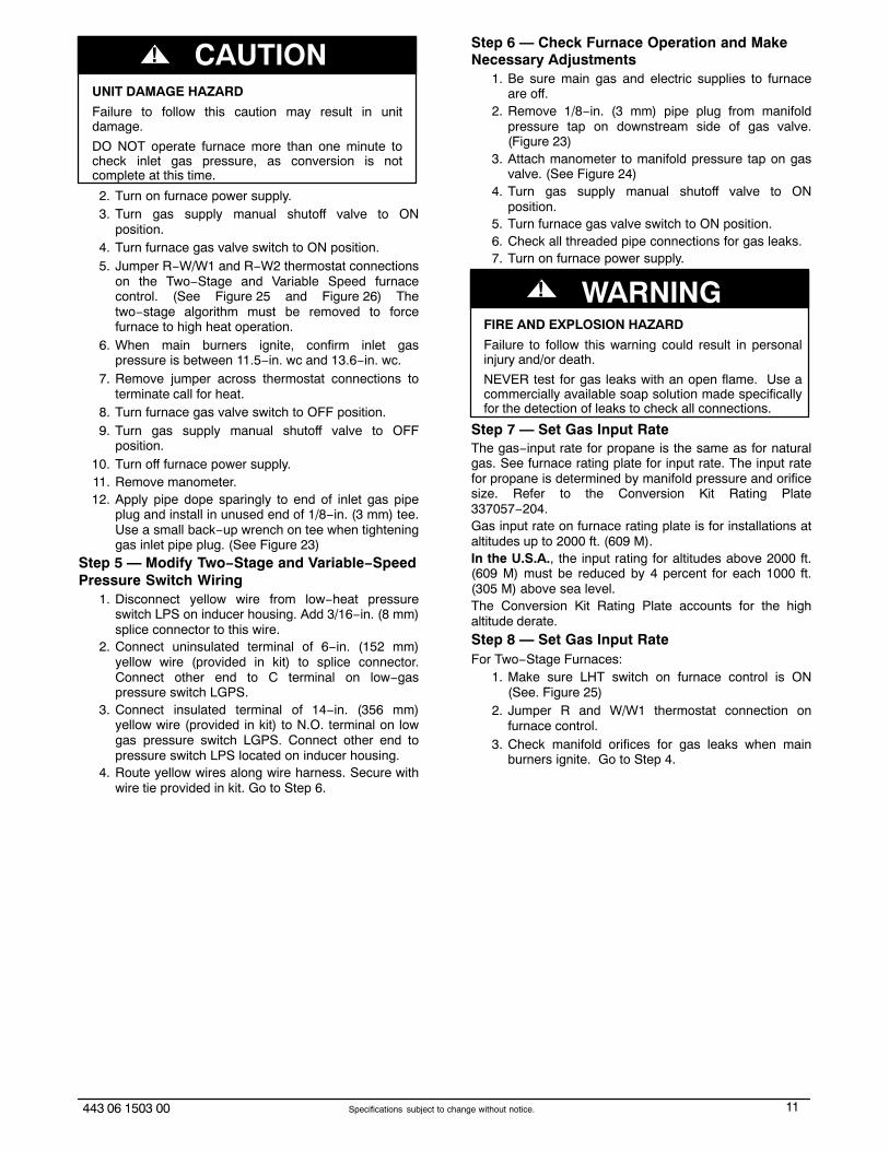
Step 6 — Check Furnace Operation and MakeNecessary Adjustments
1. Be sure main gas and electric supplies to furnaceare off.
2. Remove 1/8−in. (3 mm) pipe plug from manifoldpressure tap on downstream side of gas valve.(Figure 23)
3. Attach manometer to manifold pressure tap on gasvalve. (See Figure 24)
4. Turn gas supply manual shutoff valve to ONposition.
5. Turn furnace gas valve switch to ON position.6. Check all threaded pipe connections for gas leaks.7. Turn on furnace power supply.
FIRE AND EXPLOSION HAZARD
Failure to follow this warning could result in personalinjury and/or death.
NEVER test for gas leaks with an open flame. Use acommercially available soap solution made specificallyfor the detection of leaks to check all connections.
! WARNING
Step 7 — Set Gas Input RateThe gas−input rate for propane is the same as for naturalgas. See furnace rating plate for input rate. The input ratefor propane is determined by manifold pressure and orificesize. Refer to the Conversion Kit Rating Plate337057−204.Gas input rate on furnace rating plate is for installations ataltitudes up to 2000 ft. (609 M).In the U.S.A., the input rating for altitudes above 2000 ft.(609 M) must be reduced by 4 percent for each 1000 ft.(305 M) above sea level.The Conversion Kit Rating Plate accounts for the highaltitude derate.Step 8 — Set Gas Input RateFor Two−Stage Furnaces:
1. Make sure LHT switch on furnace control is ON(See. Figure 25)
2. Jumper R and W/W1 thermostat connection onfurnace control.
3. Check manifold orifices for gas leaks when mainburners ignite. Go to Step 4.
12 443 06 1503 00Specifications subject to change without notice.
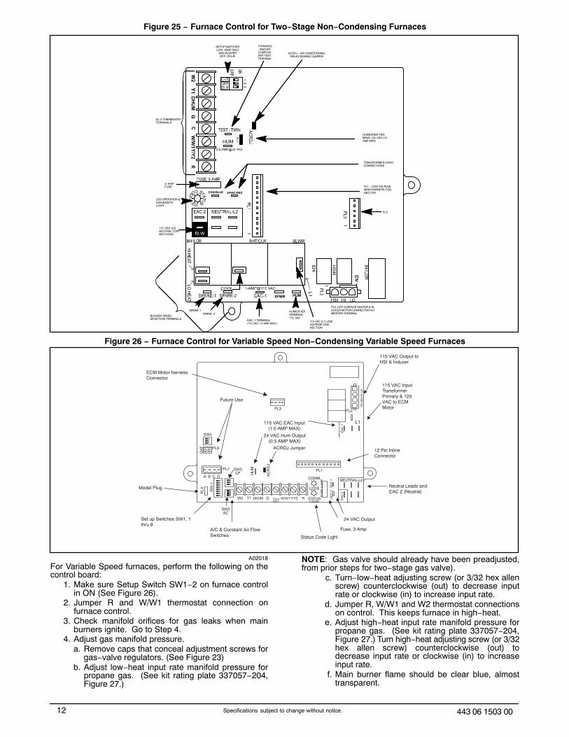
Figure 25 − Furnace Control for Two−Stage Non−Condensing Furnaces
SETUP SWITCHESLOW−HEAT ONLY
AND BLOWEROFF−DELAY
TWINNINGAND/OR
COMPON-ENT TESTTERMINAL
PL3
PL1 − LOW VOLTAGEMAIN HARNESS CON-NECTOR
TRANSFORMER 24VACCONNECTIONS
PL2−HOT SURFACE IGNITOR & IN-DUCER MOTOR CONNECTOR HU-MIDIFIER TERMINAL
ACRDJ − AIR CONDITIONINGRELAY DISABLE JUMPER
115 VAC (L1) LINEVOLTAGE CON-NECTION
EAC−1 TERMINAL(115 VAC 1.0 AMP MAX.)
SPARE−2SPARE−1
COM/BLUE
115−VAC (L2)NEUTRAL CON-NECTIONS
24−V THERMOSTATTERMINALS
HUMIDIFIER TER-MINAL (24−VAC 0.5AMP MAX)
3−AMPFUSE
LED OPERATION &DIAGNOSTICLIGHT
24VAC/RED
BLOWER SPEEDSELECTION TERMINALS
HUMXFMR
HUMIDIFIERTERMINAL115−VAC
Figure 26 − Furnace Control for Variable Speed Non−Condensing Variable Speed Furnaces
Model Plug
Set up Switches SW1, 1 thru 8
A/C & Constant Air FlowSwitches Status Code Light
Fuse, 3 Amp
24 VAC Output
Neutral Leads and EAC 2 (Neutral)
12 Pin InlineConnector
115 VAC InputTransformerPrimary & 120VAC to ECMMotor
115 VAC Output to HSI & Inducer
ECM Motor harnessConnector
Future Use
115 VAC EAC Input(1.0 AMP MAX)
24 VAC Hum Output(0.5 AMP MAX)
ACRDJ Jumper
OAT PL9
A B C D
PL4
HU
M
AC
RD
J
PL7
W2 Y1 DHUM G Com24V
W/W1Y/Y2 R
COMM
LEDS
STATUSCODE
FU
SE
3-A
MP
SE
C-2
S
EC
-1
EA
C-2
NEUTRAL-L2
PL1
PL3
EA
C-1
1-A
MP
@11
5 V
AC L1
PL2
VS
HS
I HI L
O
SW4
SW
-1
SW2AC
SW3CF
A02018
For Variable Speed furnaces, perform the following on thecontrol board:
1. Make sure Setup Switch SW1−2 on furnace controlin ON (See Figure 26).
2. Jumper R and W/W1 thermostat connection onfurnace control.
3. Check manifold orifices for gas leaks when mainburners ignite. Go to Step 4.
4. Adjust gas manifold pressure.a. Remove caps that conceal adjustment screws for
gas−valve regulators. (See Figure 23)b. Adjust low−heat input rate manifold pressure for
propane gas. (See kit rating plate 337057−204,Figure 27.)
NOTE: Gas valve should already have been preadjusted,from prior steps for two−stage gas valve).
c. Turn−low−heat adjusting screw (or 3/32 hex allenscrew) counterclockwise (out) to decrease inputrate or clockwise (in) to increase input rate.
d. Jumper R, W/W1 and W2 thermostat connectionson control. This keeps furnace in high−heat.
e. Adjust high−heat input rate manifold pressure forpropane gas. (See kit rating plate 337057−204,Figure 27.) Turn high−heat adjusting screw (or 3/32hex allen screw) counterclockwise (out) todecrease input rate or clockwise (in) to increaseinput rate.
f. Main burner flame should be clear blue, almosttransparent.
13443 06 1503 00 Specifications subject to change without notice.
g. Remove jumper across R, W/W1 and W2 afterhigh−heat adjustment.
h. Replace caps that conceal gas−valve−regulatoradjustment screws.
5. Turn setup switch LHT (two−stage) or SW−2(variable speed) switch to OFF position.
6. Turn furnace gas valve switch to OFF.7. Turn off furnace power supply.8. Remove manometer and replace manifold pressure
tap plug. (See Figure 23)NOTE: Use propane−gas−resistant pipe dope to preventgas leaks. DO NOT use Teflon tape.
9. Turn on furnace power supply.10. Turn furnace gas valve switch to ON position.11. Set room thermostat to call for heat.12. Check pressure tap plug for gas leaks when main
burners ignite.13. When correct input is obtained, main burner flame
should be clear blue, almost transparent. (SeeFigure 14)
14. Observe unit operation through two completeheating cycles. See sequence of operation infurnace Installation, Start−Up, and OperatingInstructions.
15. Set room thermostat to desired temperature.
Step 9 — Check Low Gas Pressure SwitchOperationThe newly installed low gas pressure switch is a safetydevice used to guard against adverse burner operating
characteristics that can result from low gas supplypressure. Switch opens at not less than 6.5 in. w.c. andcloses at no greater than 10.2 in. w.c.This switch also prevents operation when the propane tanklevel is low which can result in gas with a highconcentration of impurities, additives, and residues thathave settled to the bottom of the tank. Operation underthese conditions can cause harm to the heat exchangersystem. This normally open switch closes when gas issupplied to gas valve under normal operating pressure.The closed switch completes control circuit. Should aninterruption or reduction in gas supply occur, the gaspressure at switch drops below low gas pressure switchsetting, and switch opens. Any interruption in control circuit(in which low gas pressure switch is wired) quickly closesgas valve and stops gas flow to burners.When normal gas pressure is restored, the system mustbe electrically reset to reestablish normal heatingoperation. Before leaving installation, observe unitoperation through two complete heating cycles. During thistime, turn gas supply to gas valve off just long enough tocompletely extinguish burner flame, then instantly restorefull gas supply. To ensure proper low gas pressure switchoperation, observe that there is no gas supply to burnersuntil after hot surface ignitor begins glowing.
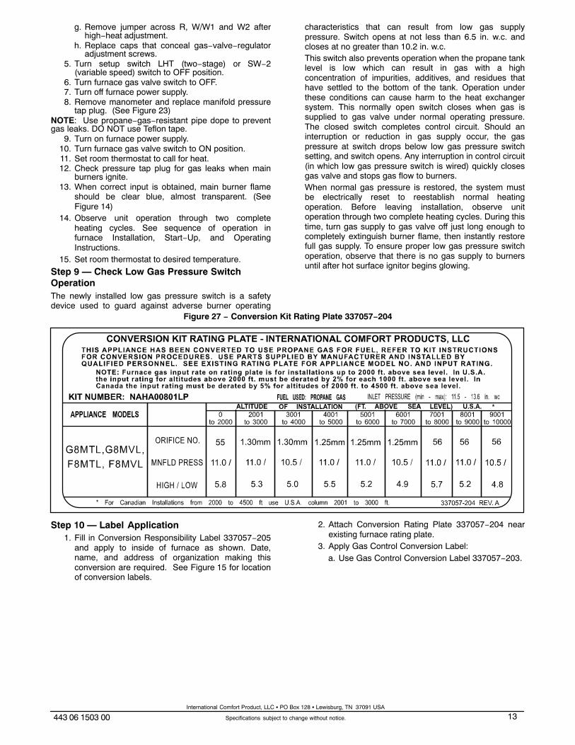
Figure 27 − Conversion Kit Rating Plate 337057−204
Step 10 — Label Application1. Fill in Conversion Responsibility Label 337057−205
and apply to inside of furnace as shown. Date,name, and address of organization making thisconversion are required. See Figure 15 for locationof conversion labels.
2. Attach Conversion Rating Plate 337057−204 nearexisting furnace rating plate.
3. Apply Gas Control Conversion Label:a. Use Gas Control Conversion Label 337057−203.
International Comfort Product, LLC � PO Box 128 � Lewisburg, TN 37091 USA