Embed Size (px)
DESCRIPTION
Natural Gas-Fired Combined-CyclePower Plant
Citation preview

s
HD9685U6R35v.13
Natural Gas-Fired CombinedCycle Power Plant Alternativefor the Railbelt Region ofAlaska
Volume XUI
Eb co Services Incorporated
August 1982
Prepared for the Office of the GovernorState of AlaskaDivision of Policy Development and Planningand the Governor's Policy Review Committeeunder Contrad 2311204417

LEGAL NOTICE
This report was prepared by Battelle as an account of sponsoredresearch activities. either Sponsor nor Battelle nor any person acting
on behalf of either:
MAKES ANY WARRANTY OR REPRESENTATION, EXPRESS ORIMPLIED, with respect to the accuracy, completeness, or usefulness ofthe information contained in this report, or that the use of any information, apparatus, process, or composition disclosed in this report may not
infringe privately owned rights; or
Assumes any liabilities with respect to the use of, or for damages resulting from the use of, any information, apparatus, process, or composition
disclosed in this report.

, :~,
Natural Gas-Fired Combined-CyclePower Plant Alternative for theRailbelt Region of Alaska
Volume XIII
Ebasco Services IncorporatedBellevue, Washington 98004
August 1982
Prepared for the Office of the GovernorState of AlaskaDivision of Policy Development and Planningand the Governor's Policy Review Committeeunder Contract 2311204417
Batte11 ePacific Northwest LaboratoriesRichland, Washington 99352
: .q.,

ACKNOWL EDGMENTS
The major portion of this report was prepared by the Bellevue, Washington,
and Newport Beach, California, offices of Ebasco Services Incorporated. Their
work includes the Introduction, Technical Description, Environmental and Engi
neering Siting Constraints, Environmental and Socioeconomic Considerations and
Institutional Considerations. Capital cost estimates were prepared by
S. J. Groves and Sons of Redmond, Washington, and reviewed by the Ebasco cost
estimating department in New York City. Cost of energy estimates were pre
pared by Battelle, Pacific Northwest Laboratories of Richland, Washington.
iii

PREFACE
The state of Alaska, Office of the Governor, commissioned Battelle,Pacific Northwest Laboratories (Battelle-Northwest) to perform a RailbeltElectric Power Alternatives Study. The primary objective of this study was to
develop and analyze long-range plans for electrical energy development for theRailbelt Region (see Volume I). These plans will be used as the basis for
recommendations to the Governor and Legislature for Railbelt electric powerdevelopment, including whether Alaska should concentrate its efforts on
development of the hydroelectric potential of the Susitna River or pursue
other electric power alternatives.
The availability of low cost natural gas in the Cook Inlet Region hasresulted in the development of an electric power system based largely on use
of natural gas for electricity generation. Continued use of natural gas for
electricity production may present operational system planning, cost and
environmental advantages in comparison with alternative energy resources.
The operational system planning and potential cost advantages of continued natural gas use are related largely to the conversion technologiesavailable for use with natural gas. Natural gas is suitable for use with
combustion turbines and combined-cycle plants. These technologies provide
good operational flexibility, being suitable for both baseload and loadfollowing operation. Combustion turbines and, to a lesser extent, combinedcycle plants are available in relatively small unit capacities and are modularin nature. These characteristics, combined with relatively short construction
lead times, facilitate capacity addition planning. Finally, capital costs ofcombustion turbines and combined-cycle plants are generally modest. This
characteristic, combined with short construction lead times, results in lowcapital investment for natural gas-fired facilities.
Environmental advantages of continued natural gas use accrue from theclean products of natural gas combustion and from the relatively low waste
heat rejected from certain natural gas-based conversion technologies. Naturalgas combustion products contain no particulates or oxides of sulfur. Formation
of nitrogen oxides is controlled in combustion turbines and combined-cycle
v

plants by water injection. Combined-cycle plants operate at high conversion
effectiveness, minimizing the waste heat rejected to the environment.
Continued use of natural gas for generation of electricity, while pre
senting the advantages discussed above, is also beset by potentially severeconstraints. Chief among these is the continued availability of natural gas
at prices competitive with other primary energy resources, and provisions of
the Fuels Use Act restricting use of natural gas for electricity generation.
An assessment of future natural gas availability and prices in the RailbeltRegion, conducted in conjunction with the Railbel,t Electric Power Alternatives
Study (Battelle 1982), inuicates that under certain conditions, natural gas
supplies will continue to be available to the Railbelt Region, albeit at
higher prices than in the past. It also appears that exemption from provision
of the Fuels Use Act might be obtained under certain conditions.
Thus, in view of the potential advantages presented by contrived natural
gas use for el,ectricity generation, and because of the possibility of avoiaing
the chief constraints to future use of natural gas, it appeared to be desir
able to examine in depth one or more of the electric generation technologies
suitable for continued use of natural gas for electricity generation in the
Railbelt Region.
Conversion technologies suitable for use with natural gas include steam
electric plants, combustion turbines, combined-cycle plants and fuel cells. A
combined-cycle plant was selected for study for several reasons. Combinea
cycle plants exhibit very favorable conversion efficiencies compared to combus
tion turbines or steam-electric units. The technology, though relatively new,
is well established in the utility industry, including two Alaskan applica
tions. Though greater than for combustion turbines, costs of combined-cycle
plants are generally less than costs of comparable steam-electric facilities.
Many plant components, such as the combustion turbines, are factory-assemblea,
minimizing the cost premiums and longer construction times often associated
with Alaskan installations. Available plant sizes (90 MW and greater) are
suitable for the modest growth in electrical demand forecast for the Railbelt
Region. This report, Volume XIII of a series of seventeen reports, documents
the findings of this study.
vi

Other power-generating alternatives selected for in-oepth study included
pulverized coal steam-electric power plants, the Chakachamna hydroelectric
project, the Browne hydroelectric project, large wind energy conversion sys
tems and coal-gasification combined-cycle power plants. These alternatives
are examined in the following reports:
Ebasco Services, Inc. 1982. Coal-Fired Steam-Electric Power PlantAlternatives for the Railbelt Region of Alaska. Prepared by EbascoServices Incorporated and Battelle, Pacific Northwest Laboratoriesfor the Office of the Governor, State of Alaska, Juneau, Alaska.
Ebasco Services, Inc. 1982. Chakachamna Hydroelectric Alternativefor the Railbelt Region of Alaska. Prepared by Ebasco ServicesIncorporated and Battelle, Pacific Northwest Laboratories for theOffice of the Governor, State of Alaska, Juneau, Alaska.
Ebasco Services, Inc. 1982. Browne Hydroelectric Alternative forthe Railbelt Region of Alaska. Prepared by Ebasco Services Incorporated and Battelle, Pacific Northwest Laboratories for the Officeof the Governor, State of Alaska, Juneau, Alaska.
Ebasco Services, Inc. 1982. Wind Energy Alternative for theRailbelt Region of Alaska. Prepared by Ebasco Services Incorporatedand Battelle, Pacific Northwest Laboratories for the Office of theGovernor, State of Alaska, Juneau, Alaska.
Ebasco Services, Inc. 1982. Coal-Gasification Combined-Cycle PowerPlant Alternative for the Railbelt Region of Alaska. Preparea byEbasco Services Incorporated and Battelle, Pacific NorthwestLaboratories for the Office of the Governor, State of Alaska,Juneau, Alaska.
vi i

~
SUMMARY
Potential operational, systems planning, cost and environmental advan
tages may accrue from continued use of natural gas for generation of electric
energy in the Railbelt Region. The most promising currently available technology for future capacity addition using natural gas appears to be natural
gas-fired combined-cycle plants. The purpose of this study is to examine the
technical, economic, environmental and institutional characteristics of
natural gas-fired combined-cycle plants of suitable capacity for the Railbelt
Region.
The plant design selected for study is a nominal 200-MW natural gas-fired
combined-cycle plant utilizing two combustion turbines of 74.5 MW capacity
each ana a heat recovery steam generator supplying a steam turbine generator
of 50 MW rated capacity. Gross plant rating is thus 208 MW; net rating, less
internal loads, is 198 MW at standard conditions. The annual average heat
rate is estimated to be approximately 8200 Btu/kWh. A forced outage rate of
8 percent and a scheduled outage rate of 7 percent would provide an equivalent
annual availability of 86 percent. Heat rejection is by mechanical draft wet/
dry cooling tower. The plant would be located in the Beluga area, northwest
of Cook Inlet. Natural gas is assumed to be supplied by pipeline from the
Beluga Field. Power would be transmitted by 345-kV line approximately 75 miles
to the proposed Anchorage-Fairbanks intertie.
Overnight capital cost for the proposed plant was estimated to be
1001 S/kW. Working capital (30-day emergency distillate supply plus 30-day
O&M costs) was estimated to be 52 ~/kW. Fixed and variable operation and main
tenance costs were estimated to be 7.25 ~/kW/yr and 1.69 mills/kWh, respec
tively. Levelized busbar energy costs were estimated for various capacity
factors and years of first commercial operation using forecasted Cook Inlet
natural gas prices prepared elsewhere in the Railbelt Electric Power Alterna
tives Study. For a 1990 startup date and an 85 percent capacity factor, a
levelizea busbar power cost of 46.5 mills/kWh was estimated. All costs are in
January 1982 dollars.
i x
Environmental effects of the proposed plant are anticipated to be moaest.
NO emissions would be controlled to the applicable NO standard of 0.014x xvolume percent of total flue gas; the only other gaseous release of potential
significance would be CO2, Gross water requirements total 1060 gpm at full
power, of which 870 gpm would be consumed and 190 gpm discharged. Estimated
land requirements for the plant are 2-1/2 acres plus land required for trans
mission line, gas pipeline and access road right-of-ways.
The estimated peak construction work force of 400 personnel could produce
severe boom-bust effects in the Beluga area.
Principal constraints to development include the continued availability
of Cook Inlet natural gas, and Fuels Use Act prohibitions on use of natural
gas for baseload electricity generation. Ample natural gas for the proposed
plant appears to be available providing Pacific Alaska liquefied natural gas
commitments are relinquished. Fuels Use Act exemptions could potentially beobtained if: a) waste heat from the plant were utilized for district heating
or process heating; or b) if the State established statutory requirements
favoring use of natural gas for electricity generation.
x
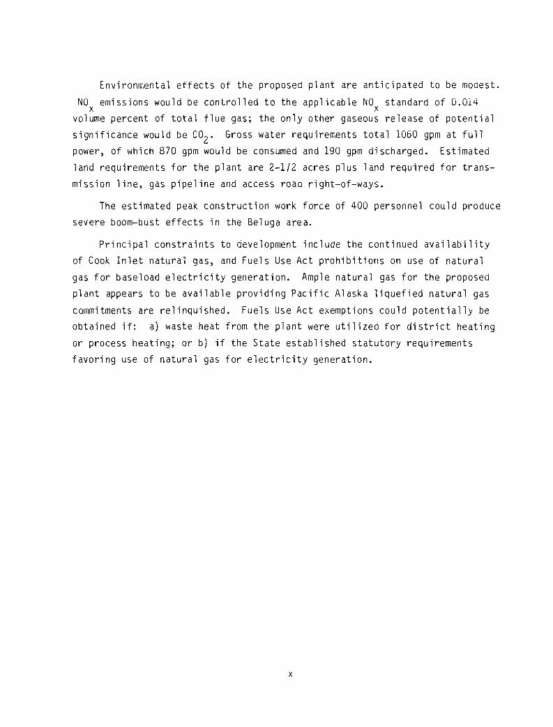
CONTENTS
ACKNOWLEDGMENTS
PREFACE
SUMMARY
1.0 INTRODUCTION
2.0 TECHNICAL DESCRIPTION
2.1 PROCESS AND AUXILIARY SYSTEMS DESCRIPTION
2.1.1 Combustion Turbine Plant
2.1.2 Steam Plant
2.1.3 Electric Plant
2.2 FUEL SUPPLY
2.3 TRANSMISSION SYSTEM.
2.4 SITE SERVICES
2.4.1 Access Roads.
2.4.2 Construction Water Supply
2.4.3 Construction Transmission Lines
2.4.4 Airstrip
2.4.5 Landing Facility
2.4.6 Construction Camp Facilities
2.5 CONSTRUCTION
2.6 OPERATION AND MAINTENANCE
2.6.1 General Operating Procedures
2.6.2 Operating Parameters
2.6.3 Plant Life
2.6.4 Operating Work Force
xi
iii
v
ix
1.1
2.1
2.1
2.4
2.7
2.18
2.23
2.26
2.27
2.29
2.29
2.29
2.29
2.30
2.30
2.30
2.32
2.32
2.34
2.35
2.35

2.6.5 General Maintenance Requirements
3.0 COST ESTIMATES.
3.1 CAPITAL COSTS
3.1.1 Construction Costs
3.1.2 Payout Schedule
3.1.3 Capital Cost Escalation
3.1.4 Economics of Scale
3.1.5 Working Capital
3.2 OPERATION AND MAINTENANCE COSTS
3.2.1 Operation and Maintenance Costs
3.2.2 Escalation
3.2.3 Economics of Scale
3.3 FUEL AND FUEL TRANSPORTATION COSTS
3.4 COST OF ENERGY •
4.0 ENVIRONMENTAL AND ENGINEERING SITING CONSTRAINTS
4.1 ENVIRONMENTAL SITING CONSTRAINTS
4.1.1 Water Resources
4.1.2 Air Resources
4.1.3 Aquatic and Marine Ecology
4.1.4 Terrestrial Ecology
4.1.5 Socioeconomic Constraints
4.2 ENGINEERING SITING CONSTRAINTS
4.2.1 Site Topography and GeotechnicalCharacteristics
4.2.2 Access Road, Transmission Line, and FuelSupply Considerations
4.2.3 Water Supply Considerations .
xii
2.35
3.1
3.1
3. 1
3.1
3.1
3.4
3.4
3.4
3.4
3.5
3.5
3.5
3.6
4.1
4.1
4.1
4.3
4.3
4.4
4.4
4.5
4.5
4.6
4.6

5.0 ENVIRONMENTAL AND SOCIOECONOMIC CONSIDERATIONS
5.1 WATER RESOURCE EFFECTS
5.2 AIR RESOURCE EFFECTS
5.3 AQUATIC AND MARINE ECOSYSTEM EFFECTS
5.4 TERRESTRIAL ECOSYSTEM EFFECTS .
5.5 SOCIOECONOMIC EFFECTS
6.0 INSTITUTIONAL CONSIDERATIONS
6.1 FEDERAL REQUIREMENTS
6.1.1 Air
6.1.2 Water
6.1.3 Solid Waste
6.1.4 Power Plant and Industrial Fuels Use Act
6.1.5 Other Federal Requirements .
6.2 STATE REQUIREMENTS .
6.3 LOCAL REQUIREMENTS
6~4 LICENSING SCHEDULE .
7.0 REFERENCES
xii i
5.1
5.1
5.3
5.3
5.4
5.4
6.1
6.1
6.1
6.4
6.5
6.6
6.8
6.9
6.9
6.10
7.1
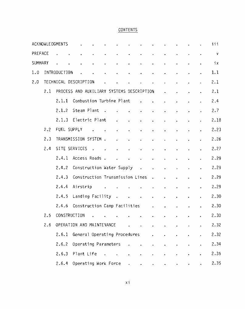
FIGURES
1. 1 Study Area
2.1 Process Flow Diagram
2.2 Plant Arrangement and Plot Plan
2.3 Plant Water Balance.
2.4 One-Line Diagram
2.5 Beluga Area Station Switchyard
2.6 Willow Substation
2.7 Construction Work Force Requirements
2.8 Project Schedule
3.1 Cost of Energy Versus Capacity Factor and Yearof First Commercial Operation.
xiv
1.3
2.3
2.9
2.15
2.20
2.22
2.28
2.31
2.33
3.8
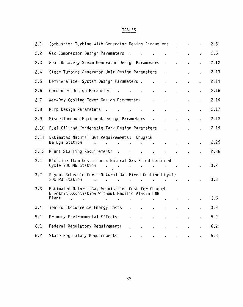
TABLES
2.1 Combustion Turbine with Generator Design Parameters
2.2 Gas Compressor Design Parameters
2.3 Heat Recovery Steam Generator Design Parameters
2.4 Steam Turbine Generator Unit Design Parameters
2.5 Demineralizer System Design Parameters
2.6 Condenser Design Parameters
2.7 Wet-Dry Cooling Tower Design Parameters
2.8 Pump Design Parameters
2.9 Miscellaneous Equipment Design Parameters
2.10 Fuel Oil and Condensate Tank Design Parameters
2.11 Estimated Natural Gas Requirements: ChugachBeluga Station
2.12 Plant Staffing Requirements
3.1 Bid Line Item Costs for a Natural Gas-Fired CombinedCycle 200-MW Station
3.2 Payout Schedule for a Natural Gas-Fired Combined-Cycle200-MW Station
3.3 Estimated Natural Gas Acquisition Cost for ChugachElectric Association Without Pacific Alaska LNGPlant
3.4 Year-of-Occurrence Energy Costs
5.1 Primary Environmental Effects
6.1 Federal Regulatory Requirements
6.2 State Regulatory Requirements
xv
2.5
2.6
2.12
2.13
2.14
2.16
2.16
2.17
2.18
2.19
2.25
2.36
3.2
3.3
3.6
3.9
5.2
6.2
6.3
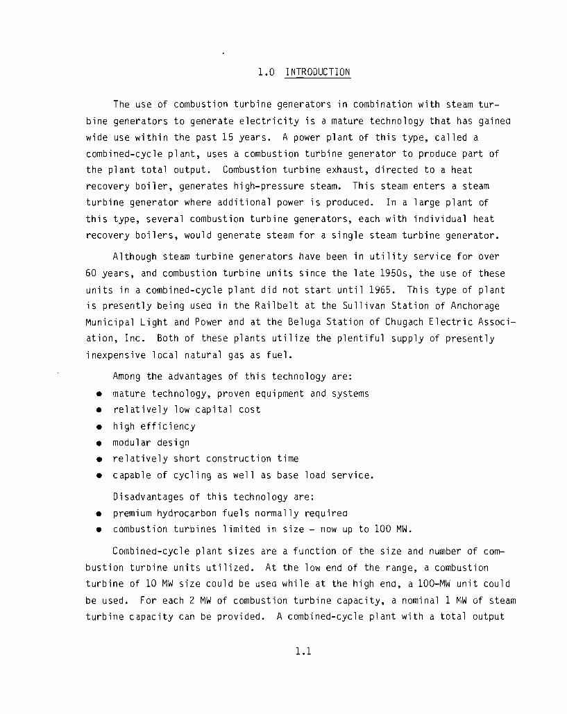
1.0 INTRODUCTION
The use of combustion turbine generators in combination with steam tur
bine generators to generate electricity is a mature technology that has gained
wide use within the past 15 years. A power plant of this type, called a
combined-cycle plant, uses a combustion turbine generator to produce part of
the plant total output. Combustion turbine exhaust, directed to a heat
recovery boiler, generates high-pressure steam. This steam enters a steam
turbine generator where additional power is produced. In a large plant of
this type, several combustion turbine generators, each with individual heat
recovery boilers, would generate steam for a single steam turbine generator.
Although steam turbine generators have been in utility service for over
60 years, and combustion turbine units since the late 1950s, the use of these
units in a combined-cycle plant did not start until 1965. This type of plantis presently being used in the Railbelt at the Sullivan Station of Anchorage
Municipal Light and Power and at the Beluga Station of Chugach Electric Associ
ation, Inc. Both of these plants utilize the plentiful supply of presently
inexpensive local natural gas as fuel.
Among the advantages of this technology are:
• mature technology, proven equipment and systems
• relatively low capital cost
• high efficiency
• modular design• relatively short construction time
• capable of cycling as well as base load service.
Disadvantages of this technology are:
• premium hydrocarbon fuels normally required
• combustion turbines limited in size - now up to 100 MW.
Combined-cycle plant sizes are a function of the size and number of com
bustion turbine units utilized. At the low end of the range, a combustion
turbine of 10 MW size could be used while at the high end, a 100-MW unit could
be used. For each 2 MW of combustion turbine capacity, a nominal 1 MW of steam
turbine capacity can be provided. A combined-cycle plant with a total output
1.1

of 100 MW, for example, could be built with two 35-MW combustion turbine
generators and one 30-MW steam turbine generator.
In the alternative described in this document, a 200-i~W nominal plant size
was selected for a potential site in the Beluga area on the west side of Cook
Inlet (Figure 1.1). This site is one of several gas fields located in the Cook
Inlet area. This plant would include two 74.5-MW natural gas-fired combustion
turbine generators, individual unfired heat recovery steam generators, and one
59-MW steam turbine generator. This design basis was used because it reflects
the size of equipment that is presently available and expected to still be
widely used in the 1985-1990 time period.
1.2

..."......G)c;0ITl
......
......
----II
!
1...
o
I- __IIIIIIIPZ
1
..o
"

2.0 TECHNICAL DESCRIPTION
2.1 PROCESS AND AUXILIARY SYSTEMS DESCRIPTION
The natural gas-fired combined-cycle turbine plant design envisioned is
based on using two currently available General Electric gas turbine genera
tors, rated approximately 74.5 MW each in combination with a General Electric
steam turbine generator rated at approximately 59 MW. Other manufacturer1s
turbines of similar size could be used within the general concept of the
design, but it must be pointed out that the specific plant-output and various
specific design parameters may be expected to change accordingly.
At International Standards Organization (ISO) referenced conditions (59°F
and sea level), plant output in the combined-cycle mode will be 208 MW gross,
of which approximately 10 MW will be utilized for internal auxiliary loads,
resulting in a net plant output of 198 MW. The heat rate of the station will
be approximately 8200 Btu/kWh.
The gas turbines can burn either natural gas, distillate oil or residual
fuel oil. The plant design is based on using Alaska natural gas, with distill
ate oil as a suggested emergency standby back-up fuel.
Main steam of 850 psig, 900°F, has been selected for the steam cycle,
based on the gas turbine exhaust temperature of 985°F. This design uses a
conservative 85°F approach temperature for the main steam, and falls in the
range of readily available steam turbine generator sets. For actual steam
generation, a conservative 40°F approach temperature has been used on the
feedwater heater, the economizer and the evaporator sections in the steam
generator. A 1500 psig main steam system could also be used on a plant of
this size; however, the actual steam production would be slightly lower at
1500 psig, 900°F, because the limiting factor on the steam generation is the
heat available in the gas above the evaporator approach temperature, i.e., atthe steam saturation temperature plus 40°F.
In an effort to more effectively utilize the lower temperature exhaust
gases, a 50 psig saturated heating steam cycle has been included in the steam
generator design. The steam turbine used for this design will be a full con
densing turbine, bottom exhausting with the condenser mounted underneath.
2.1

2.0 TECHNICAL DESCRIPTION
2.1 PROCESS AND AUXILIARY SYSTEMS DESCRIPTION
The natural gas-fired combined-cycle turbine plant design envisioned is
based on using two currently available General Electric gas turbine genera
tors, rated approximately 74.5 MW each in combination with a General Electric
steam turbine generator rated at approximately 59 MW. Other manufacturer's
turbines of similar size could be used within the general concept of the
design, but it must be pointed out that the specific plant-output and various
specific design parameters may be expected to change accordingly.
At International Standards Organization (ISO) referenced conditions (59°F
and sea level), plant output in the combined-cycle mode will be 208 MW gross,
of which approximately 10 MW will be utilized for internal auxiliary loads,
resulting in a net plant output of 198 MW. The heat rate of the station will
be approximately 8200 Btu/kWh.
The gas turbines can burn either natural gas, distillate oil or resiaual
fuel oil. The plant design is based on using Alaska natural gas, with distill
ate oil as a suggested emergency standby back-up fuel.
Main steam of 850 psig, 900°F, has been selected for the steam cycle,
basea on the gas turbine exhaust temperature of 985°F. This design uses a
conservative 85°F approach temperature for the main steam, and falls in the
range of readily available steam turbine generator sets. For actual steam
generation, a conservative 40°F approach temperature has been used on the
feedwater heater, the economizer and the evaporator sections in the steam
generator. A 1500 psig main steam system could also be used on a plant of
this size; however, the actual steam production would be slightly lower at
1500 psig, 900°F, because the limiting factor on the steam generation is the
heat available in the gas above the evaporator approach temperature, i.e., atthe steam saturation temperature plus 40°F.
In an effort to more effectively utilize the lower temperature exhaust
gases, a 50 psig saturated heating steam cycle has been included in the steam
generator design. The steam turbine used for this design will be a full con
densing turbine, bottom exhausting with the condenser mounted underneath.
2.1
L
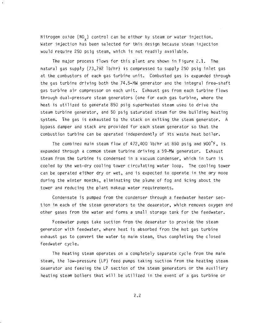
Nitrogen oxide (NO) control can be either by steam or water injection.x
Water injection has been selected for this design because steam injection
would require 250 psig steam, which is not readily available.
The major process flows for this plant are shown in Figure 2.1. The
natural gas supply (73,792 lb/hr) is compressed to supply 250 psig inlet gas
at the combustors of each gas turbine unit. Combusted gas is expanded through
the gas turbine driving both the 74.5-MW generator and the integral free-shaft
gas turbine air compressor on each unit. Exhaust gas from each turbine flows
through dual-pressure steam generators (one for each gas turbine, where the
heat is utilized to generate 850 psig superheated steam used to drive the
steam turbine generator, and 50 psig saturated steam for the building heating
system. The gas is exhausted to the stack on exiting the steam generator. A
bypass damper and stack are provided for each steam generator so that the
combustion turbine can be operated independently of its waste heat boiler.
The combined main steam flow of 472,400 lb/hr at 850 psig and 900°F, is
expanded through a common steam turbine driving a 59-MW generator. Exhaust
steam from the turbine is condensed in a vacuum condenser, which in turn is
cooled by the wet-dry cooling tower circulating water loop. The cooling tower
can be operated either dry or wet, ana is expected to operate in the dry moae
during the winter months, eliminating the plume of fog and icing about the
tower and reducing the plant makeup water requirements.
Condensate is pumped from the condenser through a feedwater heater sec
tion in each of the steam generators to the deaerator, which removes oxygen and
other gases from the water and forms a small storage tank for the feedwater.
Feedwater pumps take suction from the deaerator to provide the steam
generator with feedwater, where heat is absorbed from the hot gas turbine
exhaust gas to convert the water to main steam, thus completing the closed
feedwater cycle.
The heating steam operates on a completely separate cycle from the main
steam, the low-pressure (LP) feed pumps taking suction from the heating steam
deaerator and feeaing the LP section of the steam generators or the auxiliary
heating steam boilers that will be utilized in the event of a gas turbine or
2.2

472.400 L6/HR- SSOPSICD -"lOo·F
DRY· WETMECHANICAl.DRAFT COO~IN&TOWER
FROM DEMIN
WATER 5YSTEM
\!JJ F~OMOTHE~STM EoENtRATQR
CIRCULATING WATER ~AU)( 8O'L£~S*-.Plf'IF'S LP H"~ STEAM
.. eo,OOOL6/HR-SOPS\GSAT.EA BOlLER TOHTGCOIL.S
TOOTHERG~
TU~ UNIT
TO OTHER >til •5TM &ENEAATO~
AMBIENTAIR
!UMW
FUEL FQRwA\;lOtNG iSKID -.J
HP SAT 5TM~
~ TRAN5MISSIONSYSTEM
TRAN5~ORME.R
BSOP5IG-"I00'F .4 I.
0I8S'F
GAS T~BINE. UNIT(TYP 2PLCS)
II
BYPASS ISUPE:RHE:ATE\;l ECONOMI7..ERDAMPERS - - I
DUAL PRE'iSlJRE. S IEAM ~BJ~RAlOR(TYP 2 PLCS)
- 215~IO"L.B/HR EACH TURBINE
8YPASSEXHAUSTEoAS
r-<AIN STREAMFROM OTHER
UNIT
N
W
TO OTHf It IGAS4 UNIT COMPRESSORS
NATUUL GAS FROM SUPPLlfR'S•• J( '0· STU/HI( \13.7U LS/1I1(U5lN6 2/50(] BTU/LIJ$ GAS---~'
FIGURE 2,1. Process Flow Diagram

gas generator shutdown. The low-pressure, 50 psig, saturated steam is taken
from the steam generator LP drums or auxiliary boilers to the building steam
heating coils. Condensate returns from the heating coils are fea back to the
heating steam deaerator.
Makeup water for both feeawater cycles is supplied from the condensate
storage tank, which is steam heated to maintain a 40°F minimium condensate
temperature. For the high-pressure (HP) cycles, make-up water will be sup
plied via the condenser hotwell; LP make-up water will be supplied to the
deaerator storage tank. The condensate storage tank will be elevated slightly
to provide gravity make-up feed to the condenser hot well. A 150 gpm net
output, two-train demineralizer complete with demineralizer tank is used to
supply turbine injection water and steam generator make-up.
Plant cold start is based on using distillate fuel from the emergency
fuel tanks on one of the gas turbines. A diesel generator started on com
pressed air will provide the power for starting the gas turbine. The diesel
generator can be sized to also power the gas compressors for cold start using
gas fuel on the gas turbines if required or preferred; however, two or more
diesel generators may be needed to meet such a requirement.
It should be noted that an incoming main gas pressure of 175 psig has been
assumed in sizing the gas compressors. Larger compressors requlrlng more power
will be required if the assumed gas mains pressure is not available.
2.1.1 Combustion Turbine Plant
Each combustion turbine is a large-frame industrial-type with an axial
flow multi-staged compressor and power turbine on a common shaft. The combus
tion turbine is directly coupled to an electric generator, and can be started,
synchronized, and loaded in about one-half hour under normal conditions.
Each combustion turbine generator package also includes an inlet air fil
tration system, fuel system, water injection system, lube oil cooling system,
and various minor subsystems as required and furnished by the manufacturer.
The design parameters for each combustion turbine with generator are presented
in Table 2.1.
2.4
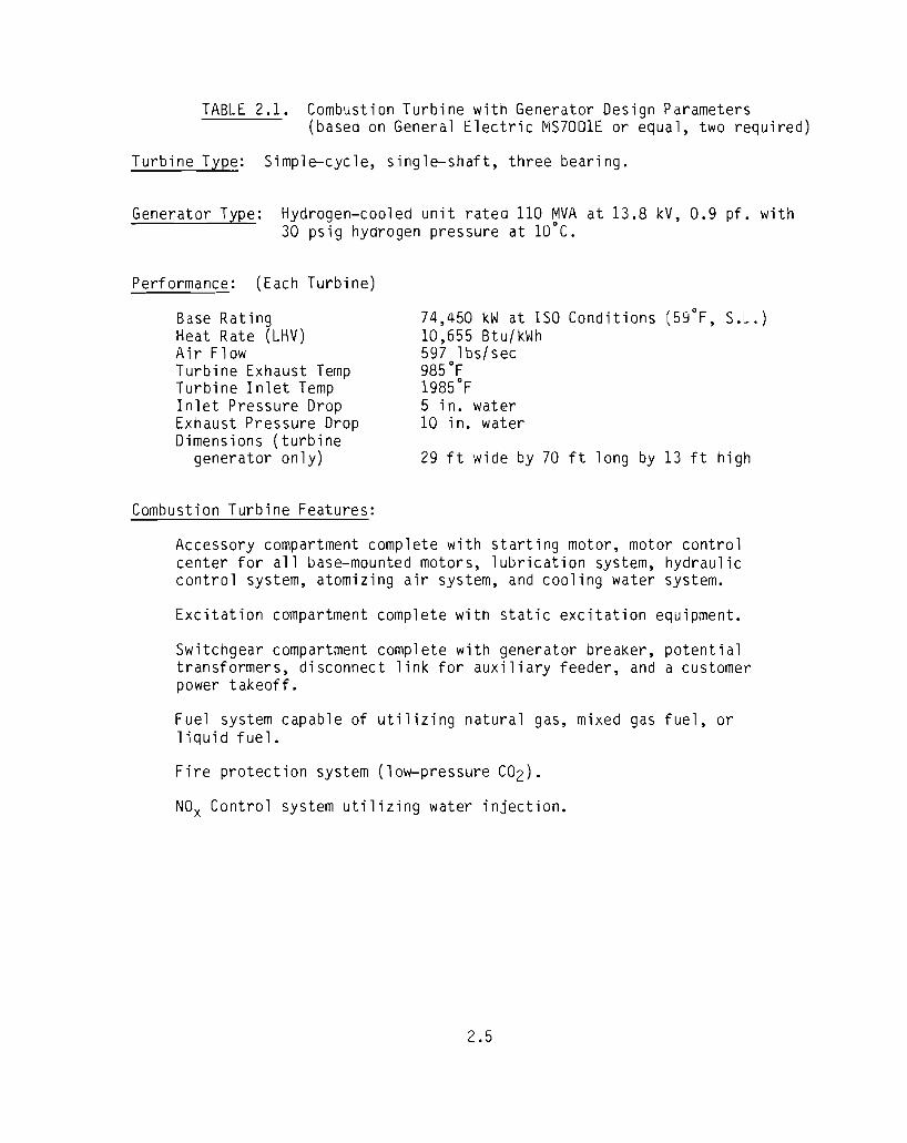
TABLE 2.1. Combustion Turbine with Generator Design Parameters(based on General Electric MS7001E or equal, two required)
Turbi ne Type: Simple-cycle, single-shaft, three bearing.
Generator Type: Hydrogen-cooled unit rated 110 MVA at 13.8 kV, 0.9 pf. with30 psig hydrogen pressure at 10°C.
Performance: (Each Turbine)
Base RatingHeat Rate (LHV)Air FlowTurbine Exhaust TempTurbine Inlet TempInlet Pressure DropExhaust Pressure DropDimensions (turbine
generator only)
Combustion Turbine Features:
74,450 kW at ISO Conditions (59°F, S.L.)10,655 Btu! kWh597 lbs!sec985°F1985°F5 in. water10 in. water
29 ft wide by 70 ft long by 13 ft high
Accessory compartment complete with starting motor, motor controlcenter for all base-mounted motors, lubrication system, hydrauliccontrol system, atomizing air system, and cooling water system.
Excitation compartment complete with static excitation equipment.
Switchgear compartment complete with generator breaker, potentialtransformers, disconnect link for auxiliary feeder, and a customerpower takeoff.
Fuel system capable of utilizing natural gas, mixed gas fuel, orliquid fuel.
Fire protection system (low-pressure C02).
NOx Control system utilizing water injection.
2.5
The inlet air filter is a high-efficiency glass fiber-type suitable for
removing particulates from the inlet air. The use of an evaporative cooler
has not been anticipated but a cooler could be adaed later if further study
justifies the expenditure.
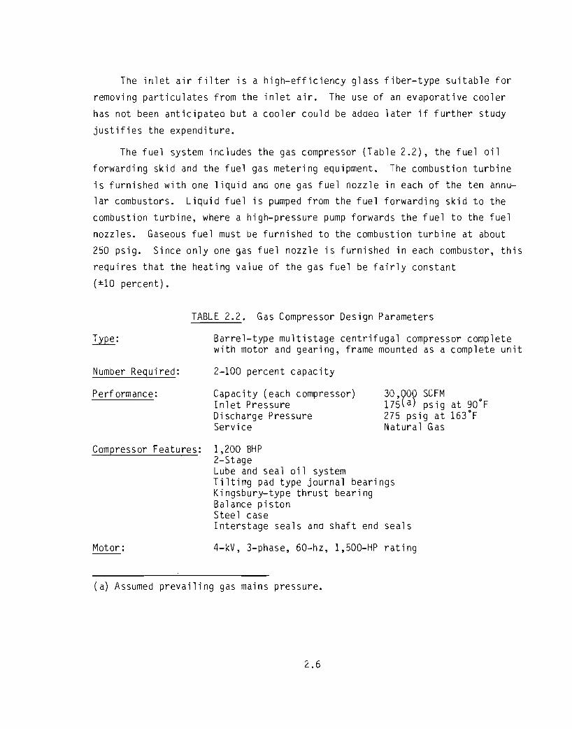
The fuel system includes the gas compressor (Table 2.2), the fuel oil
forwarding skid and the fuel gas metering equipment. The combustion turbine
is furnished with one liquid and one gas fuel nozzle in each of the ten annular combustors. Liquid fuel is pumped from the fuel forwarding skid to the
combustion turbine, where a high-pressure pump forwards the fuel to the fuel
nozzles. Gaseous fuel must be furnished to the combustion turbine at about
250 psig. Since only one gas fuel nozzle is furnished in each combustor, this
requires that the heating value of the gas fuel be fairly constant
(±10 percent).
Type:
Number Required:
TABLE 2.2. Gas Compressor Design Parameters
Barrel-type multistage centrifugal compressor completewith motor and gearing, frame mounted as a complete unit
2-100 percent capacity
Performance: Capacity (each compressor)I n1et Pre ssureDischarge PressureService
30,000 SCFM17S(a) psig at gO°F275 psig at 163°FNatural Gas
Compressor Features: 1,200 BHP2-StageLube and seal oil systemTilting pad type journal bearingsKingsbury-type thrust bearingBalance pistonSteel caseInterstage seals and shaft end seals
Motor: 4-kV, 3-phase, 60-hz, 1,500-HP rating
(a) Assumed prevailing gas mains pressure.
2.6
~---------------------------------------------

The water injection system is used to limit the emissions of oxides of
nitrogen (NO). Water is pumped from the demineralized water storage tankx
and injected directly into the combustors. This limits the peak flame tem-
perature which in turn limits the formation of thermal NO. The injectionx
rate is a function of load, ambient temperature, and the type of fuel. Typical
water injection rates at base load are about 50 gpm for gas fuel and 75 gpm
for oil per engine. Demineralized water is required to limit formation of
deposits on the turbine blades.
Other miscellaneous systems furnished with the combustion turbine include:
the starting package complete with electric motor and torque converter; a lube
oil system for bearing lubrication; a cooling water system for cooling the
lube oil system; a CO2 system for fire protection and generator purge; and a
controls system for controlling the entire gas turbine generator package.
The combustion turbines are normally operated from a central control room,
but controls provided with the unit allow either local or remote unattended
operation. Operation of the combustion turbines is essentially an automated
process, but operator presence is required to achieve proper coordination with
boiler control functions. Under normal conditions, all combustion turbines
are in operation at their base load rating.
The combustion turbines will be housed in a common building with the heat
recovery steam generators and steam turbine to facilitate plant arrangement.
The building will be 185 feet wide by 300 feet long and 90 feet nigh. The
building will be of steel construction with aluminum sandwiched insulation
siding, and will be served by an overhead crane. See Figure 2.2 for the plant
arrangement.
2.1.2 Steam Plant
The heat recovery steam generators are considered part of the steam plant,
although physically the steam generators will be housed with the gas turbines
in a common building.
The heat recovery steam generator package includes the steam generatorcomplete with ductwork from the combustion turbine to the steam generator, a
2.7

oo
COM9U5T1CMTlJ<IlINEf>l<DSTEAM Tl.A8lNE1lLllG.<SEEDE:TAIlARRG'T)
MAIN TRANSFOF.t1ERS
1'£55HALL-1-c=J
--11B8TuAIHPORT t, '===:J c=J
c=J c=Jr==:J c=::Jqp
, /SINGLE STATlI5CAMP
LAVOOWNAREA
SW{TCHYARD
I !,
~Jt ruAIRPORT
o,....
-DEMlNERAi.lZER
L~N,
I
1tr)'·O 1r_r"'::---:;7T"-,r---::::'rt?""",""~::::"__r-C,,F<A:-NE_R_A_IL_5_=-_'-_o_- -":-""';;""-~===:::T-+ __------1----------.--e=: ~ LA,~N A~ 7
"AIOT.~.
Aut HT(;5Y5 BLR
UOAIoSTSTACI
r!...'....
(~MBUSTlCN TU1'lBlNE • STEAM TLf<8INE ARRANGEMENT
2.9
FIGURE 2.2. Plant Arrangement and Plot Plan

....
bypass damper and bypass stack, and a steam generator exhaust stack. The heat
recovery steam generators are a dual-pressure design with a main steam outlet
pressure of 850 psig at 900°F, ana low-pressure outlet of 50 psig saturated
steam. Each steam generator is designed to produce one-half of the plant's
normal flow for steam, with a feedwater heater inlet temperature of 125°F.
The heat recovery steam generators are designed for continuous operation. All
steam generator controls will be located in a common area in the central
control room.
During start-up and other load conditions, the bypass damper may be
operated to provide operational flexibility. By closing the bypass damper,
the combustion turbine exhaust is routed to the stack and does not reach the
steam generator. Design parameters for the heat recovery steam generators are
shown in Table 2.3.
The main steam produced in the heat recovery steam generators is conveyed
to a common turbine generator set rated at a nominal 59,000 kW. The turbine
generator will be a direct-connected multivalve, multistage condensing unit,
mounted on a pedestal with a bottom exhaust for mounting the condenser under
the turbine. The generator is designed for maximum capability of the turbine
with a power factor of 0.9. Design parameters for the turbine generator are
shown in Table 2.4. The turbine generator set will be furnished complete with
lube oil and electrohydraulic control systems as well as the gland seal sys
tem, and the generator cooling and sealing equipment.
The turbine generator will be located on a pedestal at one end of the
common combustion turbine and steam generator building. In addition to the
combustion generators, steam generators, steam turbine and condenser, the
building will contain the feedwater pumps, condensate pumps, vacuum pumps,
deaerator, instrument and service air compressors, motor control centers,
control room, house boiler and diesel generator (see Figure 2.2). The house
boiler will be sized to provide building heating and freeze protection during
periods of unfired steam generator shut down. The diesel generator will be
sized for black start-up service.
The demineralizer will be used to supply both steam cycle make-up and
turbine injection water for NOx control. The demineralizer will be a
2.11
~:
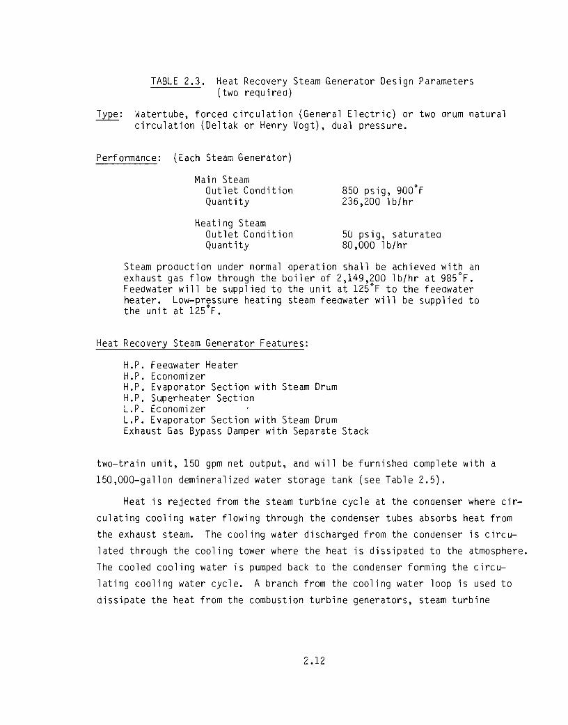
TABLE 2.3. Heat Recovery Steam Generator Design Parameters(two required)
Watertube, forced circulation (General Electric) or two drum naturalcirculation (Deltak or Henry Vogt), dual pressure.
Performance: (Each Steam Generator)
Main SteamOutlet ConditionQuantity
Heating SteamOutlet ConditionQuant ity
8S0 psig, 900°F236,200 lb/hr
SO psig, saturated80,000 lb/hr
Steam production under normal operation shall be achieved with anexhaust gas flow through the boiler of 2,149,200 lb/hr at 98SoF.Feedwater will be supplied to the unit at 12SoF to the feedwaterheater. Low-pressure heating steam feedwater will be supplied tothe unit at 12SoF.
Heat Recovery Steam Generator Features:
H.P. Feeawater HeaterH.P. EconomizerH.P. Evaporator Section with Steam DrumH.P. Superheater SectionL.P. EconomizerL.P. Evaporator Section with Steam DrumExhaust Gas Bypass Damper with Separate Stack
two-train unit, lS0 gpm net output, and will be furnished complete with a
lS0,000-gallon demineralized water storage tank (see Table 2.S).
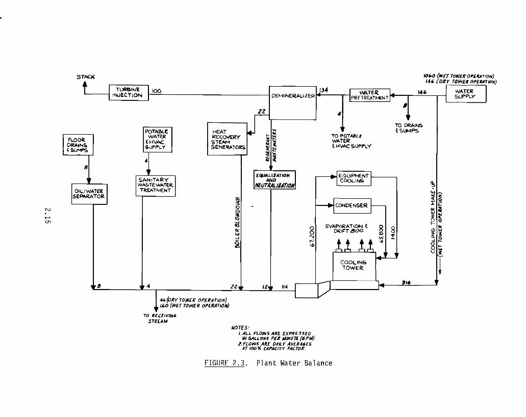
Heat is rejected from the steam turbine cycle at the condenser where cir
culating cooling water flowing through the condenser tubes absorbs heat from
the exhaust steam. The cooling water discharged from the condenser is circu
lated through the cooling tower where the heat is dissipated to the atmosphere.
The cooled cooling water is pumped back to the condenser forming the circu
lating cooling water cycle. A branch from the cooling water loop is used to
dissipate the heat from the combustion turbine generators, steam turbine
2.12
-------------------------------------------------

TABLE 2.4.
TurDi ne Type:
Generator Type:
Steam Turbine Generator Unit Design Parameters(one required)
Multistage, straight condensing, bottom exhaust
Hydrogen-cooled unit rated 59 MW at 13.8 kV 0.9 pfwith 30 psig hydrogen pressure at 10°C
Performance: Base Rati ngSteam Inlet PressureSteam Inlet TemperatureExhaust PressureExhaust TemperatureSpeed
59 MW850 psig900°F2 to 4" Hg92°F3600 rpm
Steam Turbine GeneratorFeatures: Common base-mounted with direct-drive couplings.
Accessories include multiple inlet control valves,electric hydraulic control system, lube oil systemwith all pumps and heat exchangers for cooling waterhook-up, gland steam system and generator cooling.Excitation compartment complete with staticexcitation equipment. Switch-gear compartmentcomplete with generator breaker potentialtransformers.
generator, air compressors, and other miscellaneous equipment heat exchangers
in a similar manner (Figure 2.3).
The condenser design will be single shell, two pass, with a divided water
box and hotwell. The hotwell will be designed to have sufficient storage toallow proper level control for surging and shall be properly baffled to keep
the condensate at saturation temperature. Tube sheets should be Muntz metal,
with inhibited Admiralty tubes except for 70-30 copper nickel tubes in air
removal sections and impingement areas. The condenser design data is listedin Table 2.6.
The cooling tower will be the wet-dry-type mechanical draft design of
material most suitable for the cold weather conditions found in the Beluga
area of Alaska (see Table 2.7).
2.13

TABLE 2.5. Demineralizer System Design Parameters
Demineralizer
Type:
Capacity:
Two single-train systems, each withcation, and anion, exchanger vessels
75 gpm each train, including regenerationtime
Effluent Conditions:
Demineralized Water Storage Tank
pH at 77 ofTotal dissolved solidsTotal metals
7 % 0.05t> ppm0.5 ppm
~:
Nominal capacity:
Acid Supply Tank
Capacity:
Material of Construction:
Caustic Tank
Capacity:
Material of Construction:
Recirculation and Booster Pumps
~:
Capacity:
Carbon steel, fixed dome roof, internalepoxy lining, steam heating coils,suitable insulation.
150 ,000 gal
Suitable for 40 regenerations betweenfi ll-up
Carbon steel
Suitable for 40 regenerations betweenfill-up
Carbon steel
Horizontal centrifugal, end suction, caststainless casing.
150 gpm at 150 TDH
2.14
-=----------------------------------------------
rfQUA~~ATIOH Il/tllJTRALJZDIOM
i
..,(DRY TOlNeR OPEIlATIOIV)t "0 (~ET TOWE R OPE./UTIOif)
TO ftfCf/VlN6,STREAM
HEAT ... :::RECOVERY ~ ~
ST~ ~ i&ENERATO~ ~ ~
~l
rlEQUIPMENT I ICOOLlt-t:.
,
'5,UJ>l Z<:( 0I:j::ll'~
~~~ 0
lit\DIU2 ~
3~
§~
!"4
I.
#,TO DRAl"6tSUMPS
~I ~rtf, !!JI COOLING
TOWER
4
TO POT~LE
WATER~ I-tVAC SUPPLY
T
EVAPoRATION t()l:(1~r 800
~
1
8'"r--'-.!l
1114 rIZ.
~oQ31ciijllc:141-J
2
zz.
POTA&.EWATER~HVACSUPPLY
of
~SANITARYWI>OTEWATE~
TREATMENT
"4."
~
8
01 LIWATEItSEPARATOR
FI.DO~DRAINS~SUMPS
t-'U"1
N
NOTE.S:I. ALL FLOWS AIU. EXPRESSED
IN GALLONS PER MIlfIlTl (6PJtl).~. FLOWS AffE DAILY AVU,f6lS
AT 100" CAPACITy' FACTofi.
FIGURE 2.3. Plant Water Balance

i,fUF,ilrtlIiMMNf
TABLE 2.6. Condenser Design Parameters(one required)
Condenser Type: Single shell - 2 pass
Performance: Heat LoadSaturation TemperatureInlet Water TemperatureOutlet Water TemperatureTerminal Temperature DifferenceCooling Water Flow
491 x 106 Btu/hr92°F (1.5 11 Hg)nOF87°F5°F65,800 gpm
Features: Single shell, 2 pass - 1" - 18 BWG Admiralty Tubes
Divided water box and hotwell
TABLE 2.7. ~et-Dry Cooling Tower Design Parameters(one required)
Cooling Tower Type: Parallel Path Wet-Dry
Performance: Heat Load 501 x 106 Btu/hrCooling Water Flow 67 a200 GPMInlet Water Temperature 87 FOutlet Water Temperature 72°FDesign Basis - 15°F approach to 10 percent of the time
wet bulb temperature of 57°F atAnchorage. Design coldest dry bulb 97.5percent of time is _20°F at Anchorage.
Features: One fan required for each cell. Integral air cooled heatexchanger sections for IId ry ll cold weather use.
2.16
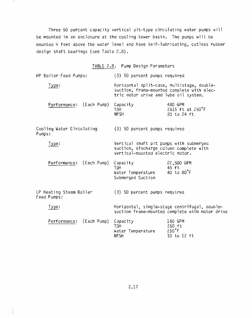
Three 50 percent capacity vertical pit-type circulating water pumps will
be mounted in an enclosure at the cooling tower basin. The pumps will be
mounted 4 feet above the water level and have self-lubricating, cutless rubber
design shaft bearings (see Table 2.8).
HP Boiler Feed Pumps:
Type:
TABLE 2.8. Pump Design Parameters
(3) 50 percent pumps required
Horizontal split-case, multistage, doublesuction, frame-mounted complete with electric motor drive and lube oil system.
Performance: (Each Pump) CapacityTDHNPSH
480 GPM2615 ft at 250°F20 to 24 ft
Cooling Water CirculatingPumps:
Type:
(3) 50 percent pumps required
Vertical shaft pit pumps with submergedsuction, discharge column complete withvertical-mounted electric motor.
Performance: (Each Pump) CapacityT~
Water TemperatureSubmerged Suction
22,500 GPM45 ft40 to 80°F
LP Heating Steam BoilerFeed Pumps:
~:
(3) 50 percent pumps required
Horizontal, single-stage centrifugal, ooublesuction frame-mounted complete with motor drive
Performance: (Each Pump) CapacityT~
Water TemperatureNPSH
2.17
160 GPM250 ft250°F10 to 12 ft
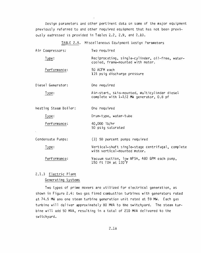
Design parameters and other pertinent data on some of the major equipment
previously referred to and other required equipment that has not been previ
ously addressed is provided in Tables 2.2, 2.9, and 2.10.
TABLE 2.9.
Air Compressors:
~:
Performance:
Diesel Generator:
Heating Steam Boiler:
Performance:
Condensate Pumps:
Performance:
2.1.3 Electric Plant
Generating Systems
Miscellaneous Equipment Uesign Parameters
Two required
Reciprocating, single-cylinder, oil-free, watercooled, frame-mounted with motor.
50 ACFM each115 psig discharge pressure
One required
Air-start, skid-mounted, multicylinder dieselcomplete with 1-1/2 MW generator, 0.8 pf
One required
Drum-type, water-tube
40,000 lb/hr50 psig saturated
(3) 50 percent pumps required
Vertical-shaft single-stage centrifugal, completewith vertical-mounted motor.
Vacuum suction, low NPSH, 480 GPM each pump,150 ft TDH at 120°F
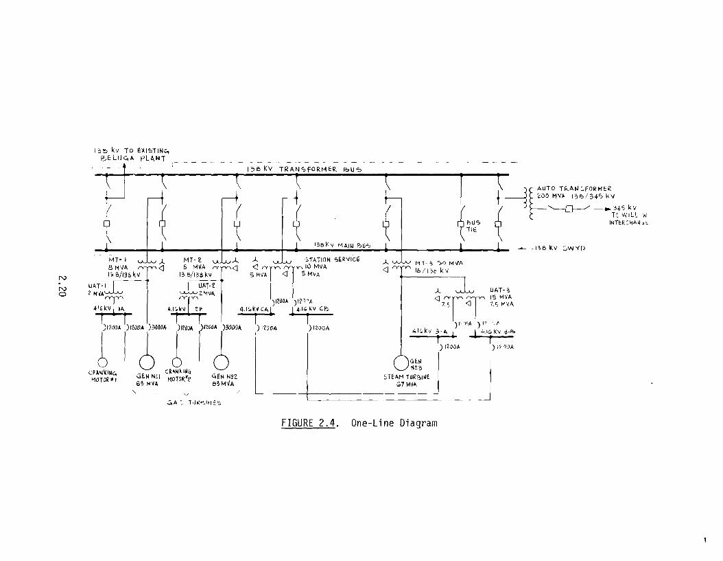
Two types of prime movers are utilized for electrical generation, as
shown in Figure 2.4: two gas fired combustion turbines with generators ratedat 74.5 MW and one steam turbine generation unit rated at 59 MW. Each gas
turbine will deliver approximately 80 MVA to the switchyard. The steam tur
bine will add 50 MVA, resulting in a total of 210 MVA delivered to the
switchyard.
2.18

TABLE 2.10. Fue1 Oil and Condensate Tank Design Parameters
Fuel Oil Tanks: Two required
Type: Floating Roof per API 650
Size: 89,580 BBL per API standard 12C 5-96" courses,120 ft diameter x 40 ft high (approximate1y 11days supply)
Service: Disti11ate fue1, specific gravity of 0.82 to 0.86
Features: Stairway, p1atform, floating-roof, seal-fixedroof support s
Condensate Tank: One required
Type: Fixed Roof - carbon steel
Size: 150,000 ga1s (approx 5 days supp1y)
Service: Condensate storage
Features: Steam heating coils, suitable insulation, plasticlined
Deaerator and Storage Tank: One required
Type: Integral connected unit with deaerator mounted ontop of 5-minute storage tank. Stainless steeltroughs and baff1e plates.
Size: 39,370 1b storage
Water Flow Out: 472,400 1b/hr
Steam Flow In: 50 psig
Design Pressure: 60 psig
Operating Pressure: 25 psia
2.19
).. l..AJJJ MT-3 ":>fJ MVA
<1~ Ibll"b kvN
No
I ~ l:> kv To E:)(I~T INc.,P.oELUC,A pLANT
(
,00 MV~ 13E:>/34? 1<\1
~(( / {i '---[}----/-- 3+'0 k Vo I ir, WILl iW
~ , \ ~ ~ ~I~? INreR~HA~.~
1%l<:v MAIL! ?>iJ'? -"----131> kv :'W'(D
MT- I vJ...u).. MT- ~ vJ...u.J... ).. v.lv STATION ",.RI/ICI:
8 HI/A <1 8 MVA <1 <1TT10 MVA13.B/138kv I3.B/13HV S MVA <1 S MV"
UAT-I i-UAT-" •
2M~~A ,Jt~ZMVA 8Tu..Lvr ~SA~V~)I~OO~ )1?0'A 7. <J 1.S !'IV"
41Gkv IA 4.1G.\(IJ U·. 4·,r.Y CA l ~ S VlnA 1'1' /.f' )""'~'" f~ )""'6-' )"'" )"00< ~:':k' T)~,::. l\,\',:,:;~
cP~NkINC. CR~IlUN" - _ JMOTOR" GEH N~I HOTOR!'2 ~EN f.le7. 5TEAH rURI?I~ESo, M~A 83MVA 1;,7 M~A
"'--- -,- v
:'A -, TdK"'"ljl~'" -
FIGURE 2.4. One-Line Diagram

Gas Turbine Generators. These are "packaged" units and as such include
all equipment required to support the turbine generator. The generators are
nominally rated at 74.5 MW, 0.9 PF, 83 MVA, with generation voltage at 13.8 kV.
The package generally includes:
1. 13.8-kV switchgear that houses the generator grounding transformer,
and generator air circuit breaker.
2. Nonsegregated phase bus duct runs to the generator and main
transformer.
3. A master control panel for overall operation and monitoring.
4. A unit auxiliary transformer 13.8/4.16 kV sized to support the ancil
lary load (assumed to be 2 MVA).
5. A 4.16-kV switchgear with air circuit breakers for other loads (e.g.,
800-hp cranking motor). The largest load (gas compressor) is fed
from the plant common 4.16-kV switchgear.
The step-up transformers for each gas turbine are rated 80 fl'IVA,
13.8/138 kV.
Steam Turbine Generator. The generator is rated 59 MW, 0.9 P.F., 67 MVA,
with generation voltage at 18 kV. The unit auxiliary transformer is a three
winding 15 MVA, 18-4.16/4.16 kV. The two secondary windings supply 4.16-kV
busses 3A and 3B. The step-up transformer is rated 50 MVA, 18/138 kV.
Station Service Transformer
This transformer is used to supply power for the steam turbine generator
auxiliaries required for startup. It is a three-winding, 10-MVA, 138-4.16/
4.16-kV transformer. The two secondary winaings feed 4.16-kV common switch
gear busses CA and CB.
Switchyard
The switchyard is basically 138 kV consisting of seven bays, shown in
Figure 2.5. One parameter for selecting this voltage was the inclusion of atie line to the existing Beluga Combustion Turbine Plant that presently has a
138-kV tie line to Anchorage.
2.21

X'
.345 KV AUTO TRAN5F
f-x X X X·
.35
~2Y../
,I J P'5l"J ')4 I V "SJI I D<J.p-sl! IX)!.I.k?i1 I I "J F"'l :,J ¥'.Jf'i ~
1 Z§J 1/31 zo J 23 1 40 t 30 1Z/ 1Z/ } Z/ ~ 54 J.5ECTJON A-A
,X
I . I WILLOWt ~ 0 ~ tI
~_+--+-=-X
-<:::::::>--+-~; I
I~r
1...
~I
~i
t-·
~It--
fl N. 'I MAIN
t~. ~;"N$F __ ~.'\I. ". _~o. I =---B-=
~i MAIN I~I TRAN~F[I No.2
r~ATIONt' ~~I ~ERV ~
l't') XFR C\I
tTJ£LINE- n. TO
\9i.EXI:5
TIN
G l ~-t"'I. SHU.' l . I '
4
T-
->- Pl.ANT . XI '
' ~ I
I I
],'T'1.",!~$F_, ---- I. No_ 3 x _ "" ~L _ ~ _,
I
N
NN
FIGURE 2.5. Beluga Area Station Switchyard

Basically, the switchyard is a two bus arrangement with a main and a
transfer bus. Each bay has a 138-kV circuit breaker, three disconnect switches
and a 138-kV tower. The bus tie bay has a 138-kV circuit breaker and two dis
connect switches.
The transmission voltage is 345 kV for export of approximately 200 MVA.
An autotransformer, 345-kV circuit breaker and two disconnect switches com
prise this portion.
2.2 FUEL SUPPLY
The plant described in this report would be located in the Beluga area,
northwest of Cook Inlet. Although a precise location is not specified, the
plant would presumably draw upon natural gas supplied from the Beluga River
Field, possibly supplemented by the nearby Lewis River and Ivan River Fields
(Figure 1.1). The existing Beluga Station (Units 1-8) of the Chugach Electric
Association is located at and supplied from the Beluga River Field.
The plant described in this report would require approximately 306 Bcf of
natural gas if operated at maximum availability (86 percent) over its antici
pated 25-year life. Although operation of maximum availability over the life
time of the plant is unlikely, partial load operation would result in a higher
heat rate, compensating for reductions in gas consumption attributable to
operation at lower capacity factor than availability.
The 1980 recoverable natural gas reserves of the Beluga River Field are
estimated to be 767 Bcf (Secrest and Swift 1982). Of these, 310 Bcf is com
mitted to Chugach Electric Association and 624 Bcf to Pacific Alaska LNG
Association, resulting in a 167 Bcf overcommitment of recoverable reserves.
Two currently untapped smaller fields, the Ivan River Field and the Lewis
River Field, lie in fairly close proximity to the Beluga River Field. The
recoverable reserves of these fields are estimated to be 26 and 90 Bcf,
respectively. Both are currently overcommitted to Pacific Alaska LNG, the
Ivan River Field at 106 Bcf and the Lewis River Field at 99 Bcf.
2.23

Under the conservative assumption that the units of the existing BelugaStation are operated at maximum availability(a) for their remaining economic
life~ Chugach will require 396 Bcf of natural gas for continued operation
beyond 1980 (Table 2.11).
Under these assumptions~ sufficient gas for continued operation of the
existing Beluga Station units for their remaining life does not appear to exist
unless: 1) Pacific Alaska LNG commitments are released~ or 2) the existence
of additional recoverable reserves is established.
If~ as thought probable~ the Pacific Alaska LNG commitments are released~
sufficient currently recoverable reserves would be available to support not
only continued operation of the existing Beluga Station throughout its anticipated life~ but also to support additional natural gas-fired generating units.
Using recoverable reserves of the Beluga Field only~ the surplus of 371 Bcf
over that required to support continued operation of the existing Beluga
Station would easily support the proposed plant. Development of the Ivan
River and Lewis River Fields would provide an additional 116 Bcf of recover
able reserves for a total surplus beyond the needs of the existing Beluga
Station of 487 Bcf~ sufficient gas for approximately 300 MW of installed
combined-cycle capacity.
In conclusion~ this analysis suggests that with relinquishment of Pacific
Alaska LNG commitments~ ample gas is available from the Beluga Field alone to
support the 20G-MW combined-cycle plant of the capacity described in this
report. Development of the Ivan River and Lewis River Fields would provide
sufficient gas to support over 300 MW of baseloaded combined-cycle capacity.Without relinquishment of the Pacific Alaska LNG commitments~ recoverable
reserves from the Beluga Area Fields are insufficient to support operation ofthe plant described in this report.
(a) Except Unit 4~ which is assumed to operate as a peaking unit at 10 percentcapacity factor.
2.24
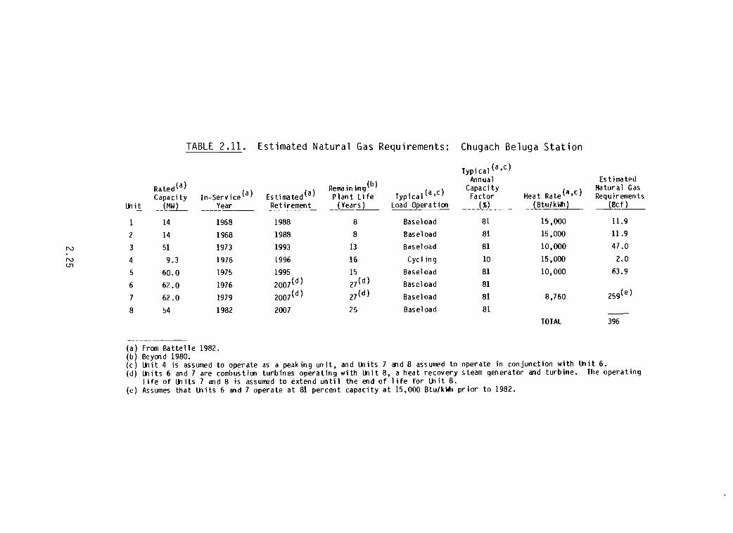
TABLE 2.1l. Estimated Natural Gas Requirements: Chugach Beluga Station
Typical(a,c)
Rated(a) Remaining(b)Annua1 Es tima ted
In-Service(a) Estimated(a) Typical(a,c)Capacity
Heat Rate(a,c)Natural Gas
Capacity Plant life factor Requiremen tsltiit _-LM!'!.L Year Ret irement _J Year_s_)_ load Opera t ion ____l!L__ (Btu/kWh ) _(B-.cf_)_
----~---
1 14 1968 1988 8 Baseload 81 15,000 11.9
2 14 1968 1988 8 Baseload 81 15,000 11.9
N 3 51 1973 1993 13 Baseload 81 10,000 47.0
N 4 9.3 1976 1996 16 Cycling 10 15,000 2.0U1
5 60.0 1975 1995 15 Baseload 81 10,000 63.9
6 62.0 1976 2007(d) 27 (d) Baseload 81
7 62.0 1979 2007(d) 27 (d) Baseload 81 8,760 259(e)
8 54 1982 2007 25 Baseload 81
TOTAL 396
---------(a) from Battelle 1982.(b) Beyond 1980.(c) ltiit 4 is assumed to operate as a peaking unit, and ltiits 7 and 8 assumed to operate in conjunction with ltiit 6.(d) lti it s 6 an d 7 are combus t ion turb in es opera tin g with lti it 8, a hea t recovery steam gen era tor and turb ine. The opera tin g
life of ltiits 7 and 8 is assumed to extend until the end of life for ltiit 8.(e) Assumes that ltiits 6 and 7 operate at 81 percent capacity at 15,000 Btu/kWh prior to 1982.

•
2.3 TRANSMISSION SYSTEM
To transmit the 200 MW generated by this combined-cycle plant, prelimi
nary calculations were made for a 75-mile, 345-kV transmission line from the
Beluga area to Willow. The following assumptions were made for this prelimi
nary estimation:
• This line was considered independent of the existing network.
• The line goes from Beluga to Willow, where the proposed AnchorageFairDanks intertie, which has sufficient capacity, will absorb the
total generated power.
• The existing system at Willow will be a 345-kV system as recommended
by Commonwealth Associates, Inc. (1981).
Three voltage levels were studied: 138 kV, 220 kV and 345 kV. A 138-kV
voltage is too low to transmit the plant's power output the required distance;
the surge impedance loading for this line would only be around 50 MW.
A 230-kV voltage line has a surge impedance loading of 135 MW. This type
of line with VAR compensation and adequate conductor size could adequately
transmit the plant output.
A 345-kV voltage line has a surge impedance loading of 300 MW. This line
may need line reactors for open line and reclosing conditions. A double
circuit 230-kV transmission line may also be an attractive alternative.
Initial investment may be higher than the 345 kV alternative because 230-
345 kV transformation at Willow has to be built and transmission towers for a
double-circuit 230 kV may be heavier than the 345-kV towers. However, I2R
losses may be lower. The results obtained from the preliminary study of these
three alternatives are as follows:
Line Size of LossesVo ltage No. of Type of Conductor I2 R Reactive
(kV) Circuits Conductor (MCM) Regulation (MW) Support
230 1 ACSR 636 11.9 percent 14.5 Capacitors
345 1 ACSR 795 3.5 percent 4.5 Reactors230 (a) 2 ACSR 636 3.8
(a) Estimated values.2.26
. jllliii

From these preliminary calculations a 34b-kV ACSR, single-circuit, 7~5 MCM is
recommended. However, additional studies will have to be done to fully jus
tify these parameters.
From an electrical point of view, interconnections with the transmission
system may substantially modify the results. This line should not be studied
independently (a complete system study is recommended). Capital investment
and line losses of alternative line configurations will have to be fully
evaluated.
The lowest initial investment will be the single-circuit 23Q-kV line, but
excessive losses appear to negate this alternative. Differential losses of
10 MW between the 345-kV and 230-kV alternates may result in $2,000,000 per
year, for a load factor of 80 percent and a cost of 3 cents a kWh for energy.
The 345 kV will have the advantage of uniform voltages with the system recom
mended by Commonwealth Associates, Inc. (1981).
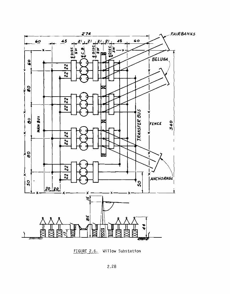
To incorporate the proposed combined-cycle plant output, a 34S-kV substa
tion at or near Willow (or some other convenient place) appears desirable and
should have a configuration as depicted in Figure 2.6. The 34b-kV lines toAnchorage, Beluga and Nenana would terminate here. This substation will pro
vide flexibility and reliability to the system load flow.
Connecting this combined-cycle plant into the system at Willow avoids the
underwater crossing of Knik Arm currently in use from the Chugach Beluga Sta
tion to Anchorage.
2.4 SITE SERVICES
The construction and operation of a 20Q-MW combined-cycle power plant
will require a number of related services to support all work activities at
the site. These site services could include the following depending upon theactual location of the power plant:
• access roads
• construction water supply
• construction transmission lines
• airstrip
• landing facility
• construction camp.2.27
274 FAIRBANkS
''0 45 ZI
.-0'- C'I
)f '"~~
())(llQ
t"\,C\I
~~ X1<
... IX)0 ~ Qc'0 II)
FENCE 0~ ~ ~
i ~ "l
" \\I )(
C\i ~C\i ....."-
x O~
""'")( f'I
'"0 ...,20 0
II )C. 'J. )(
~
FIGURE 2.6. Willow Substation
2.28
2.4.1 Access Roads
Gravel roads with a 9-inch gravel base will be required to connect the
plant site with the equipment landing facility in the Beluga area. To the
extent possible, existing roads will be used. Hence, no more than 5 miles of
new road construction is anticipated.
2.4.2 Construction Water Supply
A complete water supply,
Due to the remote nature of a
storage tank has been assumed
to fire protection purposes.should be at least 150 gpm.
storage and distribution system will be installed.
Beluga area site, a one million gallon water
with one-half of this storage capacity aeaicated
Construction water supply to the project site
2.4.3 Construction Transmission Lines
Power requirements during the construction phase will be supplied by con
structing a 25-kV transmission line tapped from an existing transmission sys
tem. For a potential Beluga site, a transmission line length of 20 miles is
assumed and will be derived from the existing Chugach Electric Association
system at either the town of Beluga or Tyonek.
2.4.4 Airstrip
For the general power plant location, the existing airstrip will be used.
It is anticipated that all personnel travel will be by air with prearranged
commercial charter carriers. All perishable goods will be flown in. Equip
ment for construction will be flown in only under extraordinary circumstances.
The largest airplane that will be able to land on the strip will be the size
of a DC-3.
The airstrip will be lighted using an above-ground distribution system to
provide for the possibility of night-time medical emergency traffic. A control
tower will not be required. All air traffic will be on a Visual Flight Rule
(VFR) basis only.
2.29
p
2.4.5 Landing Facility
The site will use the existing marine landing facility to receive all
construction materials, equipment and supplies. A paved, fenced interim stor
age area will be provided. A heavy-duty haulage road will De provided from
the landing area to the access road.
2.4.6 Construction Camp Facilities
A 50D-bed labor camp will be provided. All personnel housed in this camp
will be on single status. Provisions will be made to accommodate a work force
containing females (separate bathroom and locker facilities).
The camp will have its own well water supply. A sewage treatment facil
ity, waste incinerator, and garbage compactor will also be provided. The
complex will also have a dining hall and recreation hall.
Since it is unlikely that all personnel will be willing to come to the
job-site on single status only, a mobile home park will be provided for 16
supervisory personnel in family status. These mobile homes w·ill be approxi
mately 1000 ft2 each and could remain after completion of construction to
house vendor personnel for repair work during plant operation.
2.5 CONSTRUCTION
The number of workers necessary for construction of a 20D-MW station will
vary over the approximate 32-month construction period. Construction is esti
mated to peak in year two requiring a work force of approximately 400 person
nel. The distribution of this work force over the schedule duration is shown
in Figure 2.7.
Construction of this 20D-MW station will follow normal acceptable con
struction methods. A program of this magnitude begins with orderly devel
opment of the following requirements:
1. construction camp and utility services, such as electric light and
power, water for industrial and potable use and fire protection,
sanitary facilities, telephone communications, etc.
2.30
*"----------------------------------------------

400
350
300
250
IoU\oJ 200a.-~~Ilc: /50<:l.:{
/00
50
0 . . , ,
0 4 8 IZ 1'- 20 24 Z8 32MONTHS
NOTE.' ODES NOT INCLUDE VENDO£? PERSONNEL. OWNERPERSONNEL, OR AlE ENGIIVURS LOCATED ATSITE.
FIGURE 2.7. Construction Work force Requirements
2. temporary construction office facilities (with heating and ventila
tion furnished by contractors as required)
3. temporary and permanent access roads
4. temporary enclosed and open laydown storage facilities
5. delivery by landing craft of various types of construction equipment
and vehicles, such as earth-moving equipment, concrete and materials
hauling equipment, cranes, rigging equipment, welding equipment,
trucks and other vehicles, tools, and other related types of con
struction equipment by landing craft
6. temporary office and shop spaces for various subcontractors
2.31
F
7. settling basins to collect construction area storm runoff
8. permanent perimeter fencing and security facilities
9. safety and first aid facilities in strict compliance with OSHA
regulations.
Following completion of these site preparation activities, power plant
systems construction will be initiated. The activities involved in the over
all construction process as well as the plant's detailed development schedule
are presented in Figure 2.8.
2.6 OPERATION AND MAINTENANCE
2.6.1 General Operating Procedures
The plant has been designed for operation as a base loaded plant. Hot
starts are accomplished by starting and synchronizing the first gas turbine.
The heat recovery steam generator is then loaded and the steam turbine started.
After the steam turbine is up to speed, the second gas turbine is started, the
second steam generator is loaded and the plant is brought up to load.
Cold starts should be expected to take a minimum of 9 hours. The first
gas turbine is started and synchronized with the bypass damper positioned to
partially bypass the steam generator. The second gas turbine is started and
synchronized in a similar manner. A vacuum is pulled in the condenser using
the vacuum pumps and the steam turbine warmed through over the course of
several hours in accordance with manufacturer's instructions. The by-pass
dampers can be repositioned as required during the start-up period to control
steam flow, and opened fully when the steam turbine is loaded.
Plant systems will be operated from the control room located in the main
plant building. Some of the systems and equipment will also be controlled
from local stations. In general, controls are automatic, although operators
can override the automatic controls and operate the plant manually. To
supplement the operational controls, the station will be equipped with an
2.32
----------------------------------------------

ACTIVITY MONTHS 10T
20 30 40 50 60T
70T
ENVI RONMENTALMONITORING
PREPARE APPLICATION
AGENCY REVIEW
I I
I I
I JI •
NOTE'IT IS ASSUMED FOR SCHEDULING PUR·POSES THAT A SUITABLE SITE WILLHAVE BEEN SELECTED FOR INVESTI·GATION PRIOR TO THE INITIATION OFSTUDIES WHICH ARE ILLUSTRATED BYTHIS PROJECT SCHEDULE THIS SITESELECTION STUDY WILL REQUIRE Ap·PROXIMATEL Y 6 10 9 MONTHS.
?<P~3?r
~~?
? ?!--COMMERICAL OPERATION (MONTH 74)
~ ?I I
!::~a:wll.
Zoi=u::la:ICIlZou
~I~ SAL OF PROC/DEL
~--------41----
~ ,~ I
CJza:wwzazwIa:«ICIl
~I~~
1 . START2· PROJECT DESCRIP.3 . SCOPE APPVL4· GEN'L ARRANGEMENTS5· PURCH. ORO TURB.6· P.O. WASTE HT BLR &STM TURB.7 • PROJECT SPEC,8· DEL TURB.9· DEL WASTE HT. BLA.
10· DEL STEAM TURB.11· START DES.12 . BUDGET EST.13· COMPLETE FDN. DES.14· DET EST S.C.15 . COMP DES. C.C.16 . DET. EST CC.17· COMPLETE DES C C.18· PURCH ORD.DEMIN.19 . START SITE PREP.20· START TURB. ERECT.21 . POWER FROM SYSTEM22· START WASTE HT BUt ERECT.23' START ERECT. STM. TURB.24· START CHECK S.C.25· TRIAL OPERATION26· TRIAL OPERATION27· TRIAL OPERATION28· COM OPER. OF SC.29' START CHECK CC.30· TRIAL OPERATION31 . COMMERCIAL OPERATION
SITE SCREENING &SELECTION (SEE NOTE)
CHECKOUT, CALIB.STARTING, TESTING
PROJECT SCOPING
CONCEPTUAL DESIGN ENGR.PROCURE &CONSTR. SCHED.,ORDER COMBUSTION TUR·BINES & WASTE HEATBOILERS & STM TURB.
DETAILED ENGR. CONSTRUCTION DESIGN,PROCURE BALANCE OFPLANT
CONSTRUCT PROJECT
N
WW
FIGURE 2.8. Project Schedule
..
alarm system, fire protection system, proper lighting, and a radiotelephone
communication system. The diesel generator will be required to provide power
for safe shutdown of the unit under trip and black-out conditions.
2.6.2 Operating Parameters
Operating experience on gas-fired combined-cycle plants is somewhat
limited when compared to coal or oil-fired power plants. Conclusions on oper
ating parameters are, therefore, based on the available data on gas-firea com
bined cycle plants supplemented by EPRI data (EPRI 1979) and experience on gas
turbines and steam turbines.
It is expected that the forced outage rate will be about 8 percent.
Operational experience on some earlier plants indicates higher forced outages
in the first few years, but this is attributed to operational adjustments
required for a new type of plant, and development of the current gas turbine
design. It is expected that a slight increase in forced outages will occur as
the plant ages, but the IItechnology developmentll-type outages experienced by
some of the earlier plants are not anticipated. Variations in plant sizes
should not affect the forced outage rate provided that the same lIexperience
factor ll is characteristic of the gas turbines used.
Cycling the plant will have a negative affect on all the plant machinery.
Stress reversals encountered with peaking operation usually result in a higher
forced outage rate.
Combined-cycle plant reliability is very dependent on an adequate preven
tative maintenance program, and scheduled outrage rates can be expected to be
about 7 percent. Again, plant size will not affect the scheduled outage rate
but cycling service will necessitate more frequent inspections, which willresult in a higher scheduled outage rate.
An equivalent plant availability of approximately 86 percent should be
obtained, with the forced and scheduled outage rates of 8 percent and 7 per
cent, respectively.
The plant heat rate of approximately 8,200 Btu/kWh is not expected to
vary significantly with plant size within the range of 100 MW to 400 MW, but
should rise slightly as the plant ages. The heat rate will, however, vary
2.34
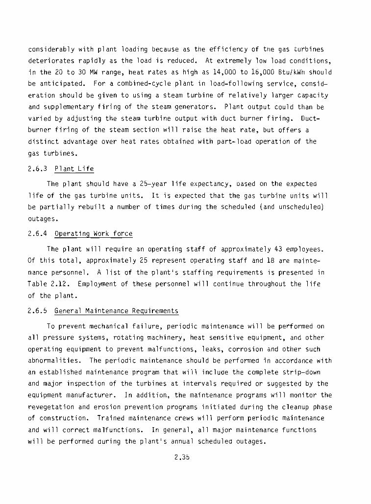
considerably with plant loading because as the efficiency of the gas turbines
deteriorates rapidly as the load is reduced. At extremely low load conditions,
in the 20 to 30 MW range, heat rates as high as 14,000 to 16,000 Btu/kWh should
be anticipated. For a combined-cycle plant in load-following service, consid
eration should be given to using a steam turbine of relatively larger capacity
and supplementary firing of the steam generators. Plant output could than be
varied by adjusting the steam turbine output with duct burner firing. Duct
burner firing of the steam section will raise the heat rate, but offers a
distinct advantage over heat rates obtained with part-load operation of the
gas turbines.
2.6.3 Plant Life
The plant should have a 25-year life expectancy, oased on the expected
life of the gas turbine units. It is expected that the gas turbine units will
be partially rebuilt a number of times during the scheduled (and unscheduled)
outages.
2.6.4 Operating Work force
The plant will require an operating staff of approximately 43 employees.
Of this total, approximately 25 represent operating staff and 18 are mainte
nance personnel. A list of the plant's staffing requirements is presented in
Table 2.12. Employment of these personnel will continue throughout the life
of the plant.
2.6.5 General Maintenance Requirements
To prevent mechanical failure, periodic maintenance will be performed onall pressure systems, rotating machinery, heat sensitive equipment, and other
operating equipment to prevent malfunctions, leaks, corrosion and other such
abnormalities. The periodic maintenance should be performed in accordance with
an established maintenance program that will include the complete strip-down
and major inspection of the turbines at intervals required or suggested by the
equipment manufacturer. In addition, the maintenance programs will monitor the
revegetation and erosion prevention programs initiated during the cleanup phaseof construction. Trained maintenance crews will perform periodic maintenance
and will correct malfunctions. In general, all major maintenance functions
will be performed during the plant's annual scheduled outages.
2.35
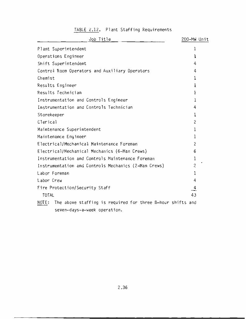
TABLE 2.12. Plant Staffing Requirements
Job Title 200-MW Unit
JIII"""""-
Plant Superintendent 1
Operations Engineer 1
Shift Superintendent 4
Control Room Operators and Auxiliary Operators 4
Chemist 1
Results Engineer 1
Results Technician 1
Instrumentation and Controls Engineer 1
Instrumentation and Controls Technician 4
Storekeeper 1
Clerical 2
Maintenance Superintendent 1
Maintenance Engineer 1
Electrical/Mechanical Maintenance Foreman 2
Electrical/Mechanical Mechanics (6-Man Crews) 6
Instrumentation and Controls Maintenance Foreman 1
Instrumentation and Controls Mechanics (2-Man Crews) 2
Labor Foreman 1
Labor Crew 4
Fire Protect ion/ Security Staff 4
TOTAL 43
NOTE: The above staffing is required for three 8-hour shifts and
seven-days-a-week operation.
2.36
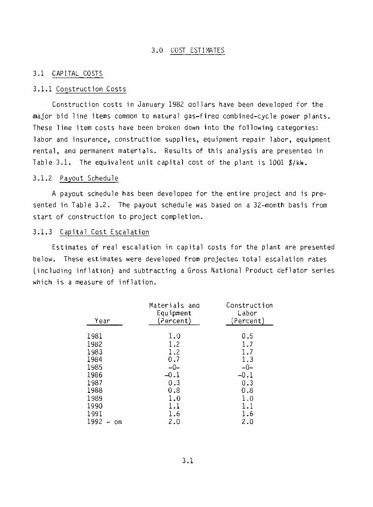
3.0 COST ESTIrvtrlTES
3.1 CAPITAL COSTS
3.1.1 Construction Costs
Construction costs in January 1982 dollars have been developed for the
major bid line items common to natural gas-fired combined-cycle power plants.
These line item costs have been broken down into the following categories:
labor and insurance, construction supplies, equipment repair labor, equipment
rental, and permanent materials. Results of this analysis are presented in
Table 3.1. The equivalent unit capital cost of the plant is 1001 ~/kW.
3.1.2 Payout Schedule
A payout schedule has been developed for the entire project and is presented in Table 3.2. The payout schedule was based on a 32-month basis from
start of construction to project completion.
3.1.3 Capital Cost Escalation
Estimates of real escalation in capital costs for the plant are presented
below. These estimates were developed from projected total escalation rates
(including inflation) and subtracting a Gross National Product deflator series
which is a measure of inflation.
Materials and ConstructionEquipment Labor
Year (PercentL (Percent)
1981 1.0 0.51982 1.2 1.71983 1.2 1.71984 0.7 1.31985 -0- -0-1986 -0.1 -0.11987 0.3 0.31988 0.8 0.81989 1.0 1.01990 1.1 1.11991 1.6 1.61992 - on 2.0 2.0
3.1
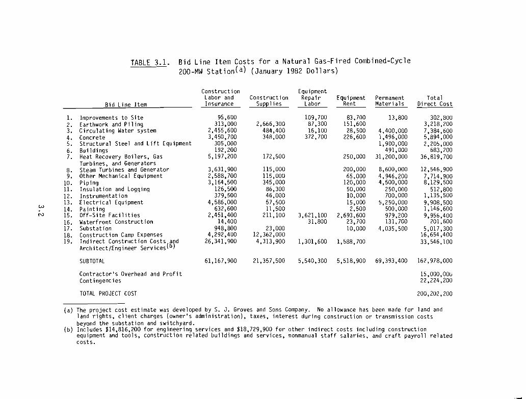
TABLE 3.1. Bid Line Item Costs for a Natural Gas-Fired Combined-Cycle200-MW Station(a) (January 1982 Dollars)
Construction EquipmentLabor and Construction Repair Equipment Permanent Tota1
Bid Line Item Insurance Supplies Labor Rent Materials Direct Cost
1. Improvements to Site 95.600 109.700 83.700 13.800 302.8002. Earthwork and Piling 313.000 2.666.300 87.300 151.600 3.218,2003. Circulating Water system 2.455.600 484,400 16.100 28.500 4.400.000 7.384,6004. Concrete 3.450,700 348.000 372.700 226.600 1.496.000 5,894.0005. Structural Steel and Lift Equipment 305.000 1.900.000 2,205.0006. Bu il dings 192.200 491.000 683.2007. Heat Recovery Boilers. Gas 5.197.200 172.500 250,000 31.200.000 36.819.700
Turbines. and Generators8. Steam Turbines and Generator 3.631.900 115.000 200.000 8.600,000 12.546,9009. Other Mechanical Equipment 2.588.700 115.000 65.000 4.946.200 7.714,900
10. Piping 3.164.500 345.000 120,000 4.500,000 8.129,50011. Insulation and Logging 126,500 86.300 50.000 250,000 512.80012. Instrumentation 379,500 46.000 10.000 700.000 1.135.50013. Electrical Equipment 4.586.000 57.500 15.000 5.250.000 9.908,500w 14 . Painting 632.600 11.500 2.500 500.000 1.146,600.
N 15. Off-Site Facilities 2,451.400 211.100 3.621.100 2.693,600 979.200 9.956,40016. Waterfront Construction 14.400 31.800 23.700 131.700 201,60017. Substation 948.800 23.000 10.000 4,035.500 5,017.30018. Construction Camp Expenses 4.292.400 12,362.000 16.654.40019. Indirect Construction Costs(ajd 26.341.900 4.313.900 1.301.600 1.588.700 33,546,100
Architect/Engineer Services b
SUBTOTAL 61.167.900 21.357,500 5.540.300 5.518.900 69.393.400 162,978.000
Contractor's Overhead and Profit 15,OOO.00lJContingencies 22.224,200
TOTAL PROJECT COST 200.202.200
(a) The project cost estimate was developed by S. J. Groves and Sons Company. No allowance has been made for land andland rights. client charges (owner's administration). taxes. interest during construction or transmission costsbeyond the substation and switchyard.
(b) Includes ZI4.816.200 for engineering services and ZI8.729.900 for other indirect costs including constructionequipment and tools. construction related buildings and services. nonmanual staff salaries. and craft payroll relatedcosts.
1

TABLE 3.2. Payout Schedule for a Natural Gas-Fired Combined-Cycle 200 MWStation (January 1982 Dollars)
Cost per Month Cumulative CostMonth (Do11ars_)_ (Do 11 ars)
l. 2,155,800 2,155,8002. 3,159,000 5,314,8003. 3,159,000 8,473,8004. 4,054,400 12,528,2005. 3,904,000 16,432,200
6. 3,904,500 20,336,7007. 4,840,700 25,177 ,4008. 3,988,400 29,165,8009. 3,814,400 32,980,200
10. 6,045,300 39,025,500
1l. 5,730,800 44,756,30012. 6,761,300 51,517,60013. 6,761,300 58,278,~00
14. 7,817,000 66,095,90015. 8,869,200 74,965,100
16. 8,869,200 83,834,30017. 8,869,200 92,703,50018. 8,869,200 101,572,70019. 8,869,200 110,441,90020. 9,166,600 119,608,500
2l. 9,166,600 128,775,10022. 9,166,600 137,941,70023. 8,237,300 146,17~,000
24. 7,499,500 153,678,50025. 7,499,500 161,178,000
26. 7,499,500 168,677 ,50027. 6,738,400 175,41!:i,90028. 6,738,400 182,154,30029. 6,248,400 188,402,70030. 6,174,100 194,576,800
3l. 2,885,800 197,462,60032. 2,739,600 200,202,200
3.3

3.1.4 Economics of Scale
For combined-cycle systems, economies of scale can be realized for many
site development costs, including temporary facilities, construction equip
ment, and construction labor. These savings, however, can only be brought
about if facility capacity is increased through an increase in component
capacity, and not through use of additional power generation units. For
example, in the range of considered plant sizes (up to approximately 300 MW),
utilization of 10Q-MW combustion turbines (current maximum unit size) and
larger heat recovery boilers would necessitate only a slight increase in the
construction work force over that required for smaller unit sizes and coula be
constructed within the same time frame. This would result in a cost reduction
on a per-megawatt basis. If capacity was increased by use of additional power
generation units, e.g., three 70-MW combustion turbines as opposed to two
100-MW units, this unit cost reduction would not be realized.
3.1.5 Working Capital
Working capital costs, including a 30-day emergency distillate supply and
30-day O&M cost, are estimated to be 52 S/kW. The cost of the emergency dis
tillate supply was based on a forecasted 1990 price for No.2 fuel oil at
8.45 S/MM Btu (Battelle 1982).
3.2 OPERATION AND MAINTENANCE COSTS
3.2.1 Operation and Maintenance Costs
The operation and maintenance costs for the 20Q-MW size plant, expressed
in January 1982 dollars, are as follows:
Fixed Costs
Staff (43 Persons)
Variable Costs
Consumables
3.4
~1,450,600 (7.25 ~/kW/yr)
1.54 mills/kWh
0.15 mills/kWh
---------------------------------_....\_-

3.2.2 Escalation
Estimated real escalation of fixed and variable operation and maintenance
costs are as follows:
3.2.3 Economics of Scale
Year
19811982198319841985198619871988198919901991
Escalation(Percent)
1.51.51.61.61.71.81.82.02.02.02.0
Costs associatea with personnel salaries are generally the major compo
nent of operation and maintenance costs for energy generating facilities. In
light of this fact, economies of scale would result from larger unit capacities
because the personnel requirements are more a function of items Qf equipment
and, therefore, would not increase in direct proportion to additional capacity.
3.3 FUEL AND FUEL TRANSPORTATION COSTS
Estimated delivered costs for Cook Inlet natural gas to the Chugach
Electric Association have been forecasted by Battelle, Pacific Northwest
Laboratories (Battelle 1982). Cases with and without relinquishment of
Pacific Alaska LNG commitments are developed in this report. In as much as it
appears that insufficient recoverable reserves would be available in the
Beluga area without relinquishment of the Pacific Alaska commitments, the
"without" Pacific Alaska prices are used in the cost-of-energy estimates that
follow. Forecasted natural gas prices to Chugach Electric Association through
the time period considered in the Railbelt Electric Power Alternatives Study
3.5

are shown in Table 3.3. Prices beyond 2010 are assumed to escalate at 2 per
cent per annum for the cost-of-energy calculations of this report. Note that
the forecasted natural gas costs of Table 3.3 are weighted costs, comprised of
gas from Beluga, Alaska Gas and service company supplies and supplemental gas
supplies.
TABLE 3.3. Estimated Natural Gas Acquisition Costfor Chugach Electric Association WithoutPacific Alaska LNG Plant, 1982 Z, 0 Per-cent Inflation (Battelle 1982)
WeightedAverage Cost
Year (~/Mcf)
1980 0.461981 0.451982 0.4619$3 0.461984 0.461985 0.511986 0.541987 0.661988 0.701989 0.78
1990 0.901991 1.531992 1.661993 1.871994 2.001995 .171996 4.461997 4.561998 4.681999 4.78
2000 4.91
3.4 COST OF ENERGY
The estimated busbar energy cost for the natural gas combined-cycle plant
described in this report is 46.5 mills per kilowatt-hour. This is a levelized
lifetime cost, in January 1982 dollars, assuming a 1990 first year of
3.6
p

I
J
commercial operation ana an 85 percent capacity factor. Estimated busbar
energy costs for other capacity factors and other startup dates are shown in
Figure 3.1. First ana subsequent year energy costs ana capital, O&M and fuel
components are shown in Table 3.4. Year-of-occurrence costs are sensitive to
escalating fuel costs.
These costs are based on the following financial parameters:
Debt Financing 100%
Equity Financing 0%
Interest on Debt 3%
Federal Taxes 0%
State Taxes 0%
Bond Life 25 years
General Inflation 0%
The escalation factors given in Sections 3.1 and 3.2 were employed. Weighted
average capital cost escalation factors were derived using a labor/material
ratio of 40 percent/60 percent.
3.7
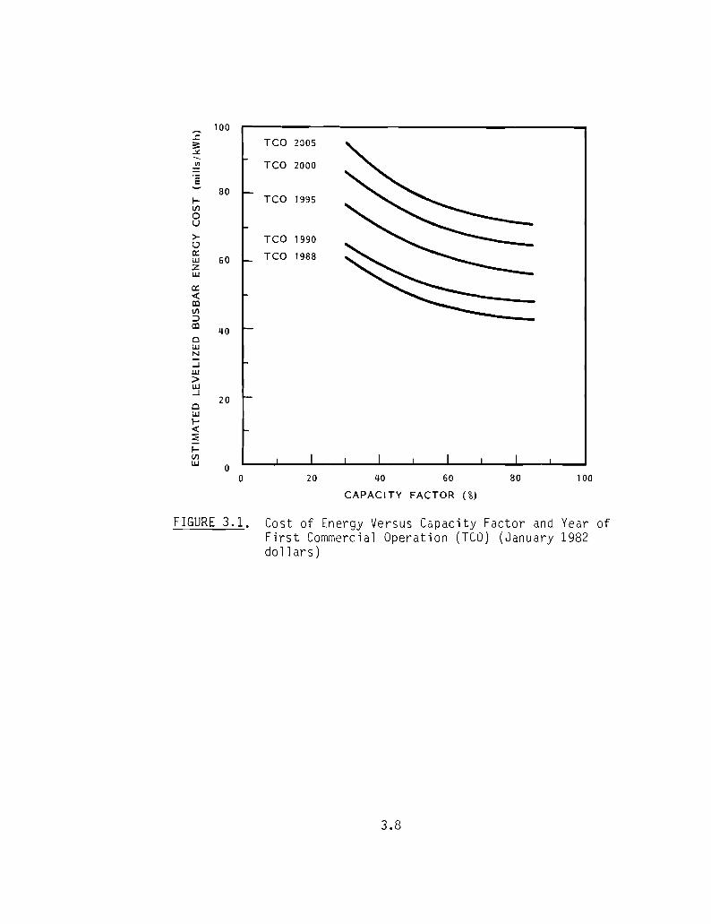
~100
.:::.TCO 2a05::
~
~ TCO 2000°E
80I- TCO 1995til0U
>- TCO 1990lJex: TCO 1988UJ 60zUJ -ex:e(COtil=>CO 40ClUJN
...JUJ>UJ...J
20ClUJl-e(::2:I-tilUJ 0
0 20 40 60 80 100
CAPACITY FACTOR (%)
FIGURE 3.l. Cost of Energy Versus Capacity Factor and Year ofFirst Commercial Operation (TeO) (January 1982dollars)
3.8
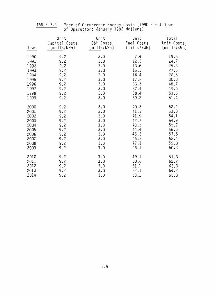
.......
TABLE 3.4. Year-of-Occurrence Energy Costs (1990 First Yearof Operation; January 1982 dollars)
Unit Unit Unit Tota1Capital Costs O&r-'l Costs Fuel Costs Unit Costs
Year (mill s/kWh) (mills/kWh) (mills/kWh) (mills/kWh)
1990 9.2 3.0 7.4 19.61991 9.2 3.0 12.5 24.71992 9.2 3.0 13 .6 25.81993 9.2 3.0 15.3 27.51994 9.2 3.0 16.4 28.61995 9.2 3.0 17.8 30.01996 9.2 3.0 36.6 48.71997 9.2 3.0 37.4 49.61998 9.2 3.0 38.4 50.61999 9.2 3.0 39.2 S1.4
2000 9.2 3.0 40.3 52.42001 9.2 3.0 41.1 53.32002 9.2 3.0 41.9 54.12003 9.2 3.0 42.7 54.92004 9.2 3.0 43.5 55.72005 9.2 3.0 44.4 56.62006 9.2 3.0 45.3 57.52007 9.2 3.0 46.2 58.42008 9.2 3.0 47.1 59.32009 9.2 3.0 48.1 60.3
2010 9.2 3.0 49.1 61.32011 9.2 3.0 50.0 62.22012 9.2 3.0 51.1 63.32013 9.2 3.0 52.1 64.22014 9.2 3.0 53.1 65.3
3.9

J
4.0 ENVIRONMENTAL AND ENGINEERING SITING CONSTRAINTS
Council of Environmental Quality regulations implemented pursuant to the
National Environmental Policy Act of 1969 require an environmental impact
statement for projects requiring licenses or permits issuea by a federal
agency. The combined-cycle plant described in this report would require
several federal permits, as discussed in Section 6. The statement must
include a discussion and evaluation of alternatives to the proposed action.This requirement is usually satisfied for power generating projects through
the evaluation of alternative sites and alternative energy generating tech
nologies. The purpose of such a study is to identify a preferred alternative
and possibly viable alternative locations for the construction and operation
of the generating station. This process can contribute to reduction in proj
ect costs through analysis of environmental and engineering siting constraints.
This section presents many of the constraints that will be evaluated
during a siting study. Special attention was given to their applicability to
the general location considered in this study. It should be realized that many
of the constraints placed upon the development of a natural gas-fired combined
cycle power plant are regulatory in nature; therefore, the discussion presented
in this section is complemented by the identification of power plant licensing
requirements presented in Section 6.
4.1 ENVIRONMENTAL SITING CONSTRAINTS
Potential environmental siting constraints include effects on water
resources, air resources, aquatic and marine ecology, terrestrial ecology and
socioeconomic considerations.
4.1.1 Water Resources
Water resource sit ng constraints generally center about two topics:
water availability and water quality. Water availability is important from
two perspectives. First, the power plant requires a reliable source of water
for efficient operation. Second, the withdrawal of water for plant uses
should not adversely impact the source from which the water is drawn. Siting
4.1
•
analyses generally attempt to minimize reduction in flow of potential water
sources while maintaining plant reliability. For this reason, it is necessary
to examine low flows as well as average yearly and monthly flows of potential
water sources. Since combined-cycle technology minimizes water usage when
compared with a similar-sized conventional stearn-electric facility, water
availability is not anticipated to be an overly constraining criterion.
Estimated plant makeup water requirements are 1060 gpm, of which 914 gpm
are for heat rejection system makeup and 156 gpm are for steam system, domes
tic and miscellaneous (see Table 5.1 in Section 5). Water supply alternatives
include use of fresh surface water sources, groundwater sources or seawater.
Seawater utilization would be limited to heat rejection system uses and a
fresh water source would be required for steam system and domestic uses.
Large rivers are not found at the Beluga location and therefore smaller
streams will have to be examined to determine their suitability as a water
source. Groundwater sources potentially exist in this area, with well yields
estimated to be as high as 1000 gpm near the larger surface water bodies.
Yields, however, range from 10 gpm to 100 gpm away from surface water bOdies.
Thus, it appears that adequate water supplies can be obtained from ground
water near surface water bodies or by use of seawater for heat rejection
system makeup and ground water for other uses. Investigation of specific
streams may reveal sources of adequate magnitude.
Existing water quality can represent a significant siting constraint.
First, receiving stream water quality standards, if particularly stringent,
could prohibit plant effluent discharge. Second, makeup water quality require
ments may mandate the provision of an extensive water treatment facility if
the quality of the water source is inferior. This consideration should not
prove restrictive at either potential plant location. The water quality of
most other surface water resources is acceptable from a makeup water manage
ment viewpoint. However, if the plant utilizes a groundwater supply system,
an extensive treatment system may be required since ground water is generally
highly mineralized.
4.2
...

1I
I 4.1.2 Air Resources
Combined-cycle gas-fired units emit only one atmospheric pollutant of
major concern--oxides of nitrogen (NOx). There are no PSD increments cur
rently set for NOx (see Section 6.1.1) and there are no nonattainment areas
in the Railbelt Region with respect to the NO standards. Therefore, therexis very little in the way of siting constraints due to atmospheric emissions
from combustion-turbine combined-cycle units.
Nevertheless, regulatory compliance will be eased somewhat by judicious
site selection. The regulatory issues discussed in Section 6.1.1 can be used
to provide some guidance in this selection. Generally, areas designated as
Class I for PSD purposes should be avoided when possible. The Tuxedni Wildlife
Refuge and the Mount McKinley National Park are the only areas in the Railbelt
Region currently designated as Class I. In addition, a nonattainment area
designated for any pollutant should be avoided if reasonable alternatives are
available. The Anchorage area is currently designated as nonattainment for
carbon monoxide. Any potential for CO emissions must be analyzed carefully
and controlled to the greatest extent possible. This may include potential
emissions due to Ilupset" conditions when the facility is not operating at its
most efficient levels, and it may also include CO emissions from secondary
sources, such as construction ana associated automobile traffic.
From a topographic point of view, enclosed areas with limited dispersion
potential, such as deep valleys or sheltered basins, should also be avoided.
The applicant will have to demonstrate that the ambient air quality standards(for NO ) will not be violated by facility operation. Compliance with these
xstandards is better assured in open, exposed locations.
4.1.3 Aquatic and Marine Ecology
Since the plant makeup and discharge requirements are relatively small (a
maximum of 1060 gpm and 160 gpm, respectively), intake entrainment and impinge
ment and wastewater discharge impacts will probably not be major site consid
erations. The major activity related to aquatic ecology performed during the
siting process will, therefore, be an identification of exclusion and avoid
ance areas to be considered in association with intake and discharge structure
4.3
development. The delineation of these areas will be based primarily upon an
inventory of fish spawning habitat and upstream migration pathways, fish nur
sery habitat and downstream migration pathways, important benthic habitat and
rare and/or endangered species and their critical habitats. Should a marine
intake or discharge be considered, impacts to the significant marine popula
tions, including Beluga whales, will be addressed, but should not represent aconstraint due to the small intake and discharge flows expected.
4.1.4 Terrestrial Ecology
Since habitat loss is generally considered to represent the most signifi
cant impact on wildlife, the prime terrestrial ecology activity related to
terrestrial ecology will be an identification of important wildlife areas,
especially critical habitat of threatened or endangered species. Based upon
this inventory, exclusion, avoidance and preference areas will be delineated
and factored into the overall plant siting process.
A number of important and sensitive species inhabit the potential site
area, including moose, caribou, brown and black bear as well as small fur
bearers, such as lynx, beaver and muskrat. Also present are significant bird
species including bald eagles and colonial nesting birds, such as seagulls,
puffins and cormorants. Appropriate consideration of these species and their
habitats will be required during the plant siting process.
4.1.5 Socioeconomic Constraints
Major socioeconomic constraints center about potential land use conflicts
and community and regional socioeconomic impacts of project activities. Two
types of potential land use conflicts must be considered: exclusionary areas,
where plant development would be prohibited; and avoidance areas, where plant
development, while possible, is generally not desirable. Potential exclu
sionary land uses will consist of those areas that contain lands set aside for
public purposes, areas protected and preserved by legislation (federal, stateor local laws), areas related to national defense, areas in which a combined
cycle installation might preclude or not be compatible with local activities
(e.g., urban areas or Indian reservations), or areas presenting safety consid
erations (e.g., aircraft facilities). Avoidance areas will generally include
4.4
r
.........
areas of proven archeological or historical importance not under legislative
protection as well as prime agricultural areas.
Minimization of the boom/bust cycle will also be a prime socioeconomic
consideration. Through the application of criteria pertaining to community
housing, population, infrastructure and labor force, this consideration will
be evaluated and preferred locations identified. Because of the potential forsignificant boom/bust-related impacts on small communities within the Beluga
area, socioeconomic impact criteria will be heavily weighted in the overallsite evaluation process.
4.2 ENGINEERING SITING CONSTRAINTS
Potential engineering siting constraints that should be considered in the
site-selection process include site topography and geotechnical character
istics, road access, transmission line access, water supply and fuel supply
considerations.
4.2.1 Site Topography and Geotechnical Characteristics
Principal topographic and geotechnical consiaerations include terrain,
soil conditions, seismic activity and the availability of borrow material. in
general, the power plant should be sited in relatively flat terrain. This
will minimize the amount of required grading ana excavation as well as mini
mize the potential for adverse environmental impacts due to rainfall runoff
transport of suspended solids to nearby waterways. The plant should be sitedabove the lOO-year floodplain of any major streams to avoid flooding.
Poor soil conditions can cause significant construction problems due to
poor suitability as a foundation for structures. The presence of highlyorganic soil (muskeg) in the Beluga area will probably require that extensive
piles be placed under major building and equipment foundations.
Potential seismic activity can also be an important site-differentiating
factor, with preference given to those sites located in regions of low seismic
activity. However, all potential Beluga sites fall within regions of high
seismic activity (Zone 3). While this will not preclude development nor dif
ferentiate between the sites, it will increase construction costs because
4.5

s
more material will be required to ensure plant foundation stability. The loca
tion and extent of all faults within the general Beluga area should be studied
during the site-selection process because the plant should not be sited in
close proximity to fault lines.
Finally, sites that contain an aaequate supply of borrow material can be
far less costly, especially if alternate sites would require haul of this
material over long distances.
4.2.2 Access Road, Transmission Line and Fuel Supply Considerations
Sitin9 the proposed power plant in close proximity to existing roads,
transmission lines ana gas pipelines would minimize the cost associated with
these required connection links and also minimize the environmental effects
associated with land disturbance. For roads, the selected route should comply
with established safety and reliability standards. For example, the maximum
allowable graae for roads is approximately 6 percent. Route selection of
roads, pipelines and transmission lines will also be affected by soil and
meteorological conditions because potential frost heave problems and other
soil-related characteristics can significantly add to the cost of road andpipeline facilities. Additional considerations for transmission line routing
include wind, temperature and prospective ice load; these factors can signifi
cantly affect transmission line design.
Accessibility to transmission is not expected to be a serious constraint
for a Beluga site due to the presence of the transmission line serving the
Chugach Electric Association Beluga Station.
4.2.3 Water Supply Considerations
The power plant requires a reliable water supply. To ensure that this
requirement is met, two criteria are generally employed during the siting
process:
• The plant should be sited within approximately 15 miles of an
acceptable source of water, and
• The plant should be sited where the maximum static head between the
water source and the end use facility (the plant itself or a makeup
water reservoir) is less than approximately 1500 feet.
4.6

The first criterion reflects the need to minimize right-of-way acquisi
tion; land disruption; associated construction-related environmental impacts;
investment and operating costs; and the potential reliability problems associ
ated with "pumps-in-series" operation. The second criterion reflects the
limits on the reliability of high-lift pumping operations. Observance of this
criterion will minimize the need for system redundancies (e.g., a duplicate
pipeline) as well as minimize the operating costs associated with water
pumping.
A discussion of potential water sources in the Beluga area is provided in
Section 4.1.1.
4.7

...
5.0 ENVIRONMENTAL AND SOCIOECONOMIC CONSIDERATIONS
The construction and operation of a 200-MW natural gas-fired combined
cycle generating facility will create changes or impacts to the land. water
and socioeconomic environments in which it is located. A summary of the
primary impacts of the plant on the environment is presented in Table 5.1.
Following preliminary plant design, these primary effects are then analyzed
and evaluated in light of existing environmental conditions to determine the
potential significance of the impact and the need for additional mitigative
measures. Further discussion of the impacts listed in Table 5.1 is provided
below.
5.1 WATER RESOURCE EFFECTS
Water resource impacts associated with the construction and operation of
a combined-cycle power plant are generally mitigated through appropriate plant
siting criteria ana through a water and wastewater management program. The
plant water system will normally employ water treatment and recycle to satisfy
regulatory requirements on discharge and to minimize water consumption.
Achievement of these water quality requirements will preclude adverse impacts
on the water resource.
A favorable attribute of natural gas-fired combined-cycle power plants is
that. on a per-megawatt-basis, these facilities require much less water for
cooling purposes than conventional ~all steam~ systems. For example. the esti
mated makeup water requirement at a 200-MW direct coal-fired steam-electric
plant is 1947 gpm (wet cooling) (Ebasco Services Incorporated 1982) compared
with an estimated 1060 gpm for the 200-MW combined-cycle plant described in
this report. The difference is attributable to the superior thermal effi
ciency of the combined-cycle plant and to the reduced steam system makeup
requirements. In addition. natural gas-fired combined-cycle power plants
produce little solid waste, and therefore minimize disposal and wastewater
treatment requirements generally associated with combustion technology byprod
ucts. Significant or difficult-to-mitigate water resource impacts should
therefore not pose restrictive constraints on the development of this type of
electric generating facility.
5.1
rrJ

TABLE 5.1. Primary Environmental Effects
Part.iculate Emissions
Sulfur Dioxic1e Emissions
Nitroqen Oxide Emissions
Water
P1ant Water RequirementsCooling Tower ~akeup
Other Requ irel11ents
Plant D;scharge RequirementsCooling Tower Slowdown
Demineralizer
Steam GeneratorsTota I
San itary Treated Waste
Floor Ora; ns
Aquatic and ~arine Ecosystems
Anadromou sF ish
Other
Terrestr i a I Ecosystem
Wi 1dlife Habitat
Food Chain
Human Presence
Land
Plant Island
Fuel Storage
Transmission
Road
Gas Pipeline
Soc i oeconomi c
Construction Work Force
Operating Work Force
Relocations
Land Use Changes
Recreation
Capital Investment
Operat; ng 1nvestment
Fue' Investment
Aesthetics
Maximum Structure Heiqht
5.2
~egligible.
~egligible.
Emissions variable - water injection controJ1ed to meet calculated~Ox standard of 0.014 percent oftotal volume of gaseous emissions.
914 gpm
146 gpm
144 gpm
12 gpm
~gpm4 gpm
gpm
No impact anticipated.
No significant impact anticipated.
Loss of habitat at the plant siteand along access road corridor.
No significant impact anticipated.
Increased human presence at pl antsite and along access roadcorr i dor.
'2 acres
1/2 acre
75 miles at 345-kV line (couldshave existing transmission corridor for much of this distance).
5 miles of gravel road.
Less than 10 mi7es of new corridor.
Peak requirement of approximately400 personnel.
43 personnel.
None.
Increased access to plant site andalong road, gas pipeline andtransmission corridors.
See I and use changes above.
70 percent witnin region.30 percent outside region.
84 oercent within region.16 percent outside region.
FlO percent within regian.
50 feet

•
5.2 AIR RESOURCE EFFECTS
Air quality impacts resulting from the operation of natural gas-fired
combined-cycle facilities are generally limited to emissions of oxides of
nitrogen (NO). Emissions of NO can be well controlled by reduction ofx xpeak combustion temperatures through water or steam injection. Sulfur oxides
are not a significant pollutant because of the low sulfur content of natural
gas. Achievement of regulatory requirements for New Source Performance Stan
dards will generally preclude any significant impact from these emissions on
the air resource.
Ice fog may be produced during cold weather conditions by water or steam
injection; however, the requirement for water or steam injection may be elimi
nated when ice fog is deemed a traffic hazard. In adaition, water vapor can
be added to the air from the cooling tower. The formation of these plumes
will be eliminated, however, by the use of a wet/dry cooling tower system. No
offsite local climatic effects of system operation will be detectable. The
assessment of impacts of this facility on broad-scale concerns, such as acid
precipitation and CO2 buildup, are not required from a regulatory viewpoint
at this time, and such impacts may be deemed "no t detectable."
As with other combustion-based technologies, operation of a natural gas
fired combined-cycle plant will release carbon dioxide to the atmosphere.
Increasing concern has been expressed regarding long-term effects of the
increase in atmospheric CO 2 apparently resulting from combustion of fossil
fuels. Of particular concern is the potential "greenhouse" effect of increased
atmospheric CO 2 concentration. No feasible measures are currently available
for control of CO 2 production other than possible regulation of the global
amounts of fossil fuels burned. No controls on CO 2 production, however,
currently exist.
5.3 AQUATIC AND MARINE ECOSYSTEM EFFECTS
Potential impacts from water withdrawal and effluent discharge will be
lowest on a per-megawatt basis for a combined-cycle plant in comparison with
conventional steam electric plants. Proper design and location of the plant's
intake and discharge structures should sufficiently mitigate any major adverse
5.3

effects. Attainment of regulatory requirements on plant discharges through
properly engineered systems will mitigate any potential effects.
5.4 TERRESTRIAL ECOSYSTEM EFFECTS
The greatest impact resulting from natural gas-fired combined-cycle power
plants on the terrestrial biota is the loss of habitat due to human distur
bance. The amount of land required is generally small, approximately 2 to
6 acres for a 200-MW plant, although a much larger area may be required for
road access and transmission and pipeline corridors (see Table 5.1). Signifi
cant populations of moose, caribou, black bear and waterfowl are located in
the Cook Inlet area. Therefore, siting studies for the actual plant location
and for road, gas pipeline, and transmission corridors should be performed to
minimize impacts to these species. A carefully selected site should not
significantly impact these populations.
Some potential exists for the disturbance of the flora and fauna due to
cooling tower drift emissions. Proper drift control devices should suffi
ciently mitigate this impact.
5.5 SOCIOECONOMIC EFFECTS
Many of the communities located near the Cook Inlet region are small in
population and have an infrastructure that is not highly developed. In light
of this, the construction and operation of a 20G-MW natural gas-fired combined
cycle plant has a high potential to impact these local communities and cause a
boom/bust cycle. These impacts can be lessened by siting a combined-cycle
plant near a community with a population greater than 500, or by siting in a
location remote from any existing population center. While a construction
camp will mitigate this impact to some degree, disruption of the area1s infra
structure must be anticipated if the facility is located near one of the
smaller communities, such as Tyonek.
Since combined-cycle is a capital-intensive technology, the largest por
tion of expenditures outside the region will be attributed to equipment.
Approximately 70 percent of the project capital expenditures will be spent in
5.4
r

the lower 48 states, while 30 percent will be spent within the Railbelt. The
allocation of operating and maintenance expenditures spent outside the Railbelt
will be approximately 16 percent. All fuel will be obtained from Railbelt
sources.
5.5
j
1~!r

6.0 INSTITUTIONAL CONSIDERATIONS
This section presents an inventory of major federal, state of Alaska, and
local environmental regulatory requirements that will be associated with the
development of a 200-MW natural gas-fired combined-cycle power plant in the
Beluga area of Cook Inlet. The inventory is divided into three sections, setting forth federal, state and local environmental licensing requirements.
Federal requirements are summarized in Table 6.1; and state requirements in
Table 6.2.
The discussion is limited to the major environmental regulatory require
ments. The identification of more specific requirements can be accomplished
only after detailed studies regarding project design and location are avail
able. These requirements could be important in Alaska where much of the land
is owned by the federal or state government.
6.1 FEDERAL REQUIREMENTS
6.1.1 Air
Air pollution controls are placed on new fuel-burning power plants through
the provisions of the Clean Air Act (CAA). The CAA is implemented primarily
through permitting programs that would ensure compliance with national ambient
air quality standards (NAAQS) and that would prevent significant deterioration
in areas where NAAQS are being met. To obtain a permit, a power plant may be
required to restrict emissions in accordance with new source performance
standards (NSPS), national emission standards for hazardous air pollutants
(NESHAP), and other, more constricting programs, such as best available con
trol technology (BACT) and lowest achievable emission rate (LAER).
The permitting program and controls to which a power plant will be subject
is partially dependent upon its location. Since the general plant location is
situated in an area in which air pollution levels are in compliance with NAAQS,
the plant will be subject to the prevention of significant deterioration (PSD)
permitting program administered by the Environmental Protection Agency (EPA)
in accordance with CAA sections 160-169.
6.1
III
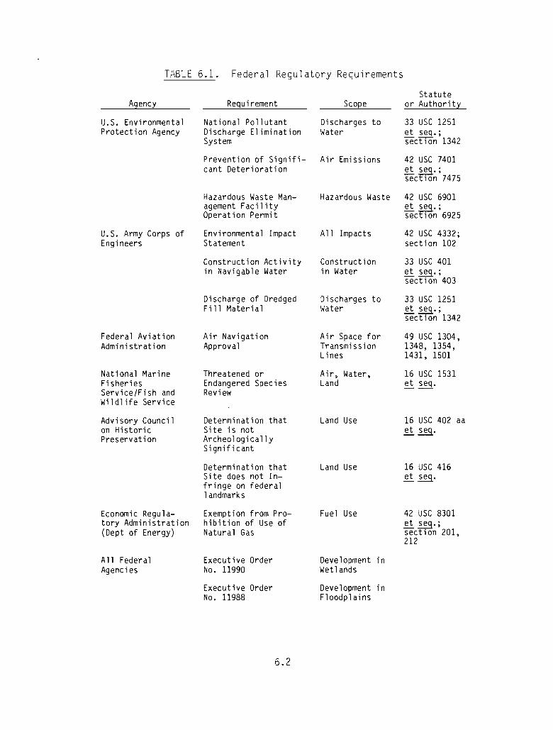
TABLE 6.1. Federal Regulatory Requirements
Agency
u.S. EnvironmentalProtection Agency
Requirement
National PollutantDischarge EliminationSystem
Scope
Discharges toWater
Statuteor Authority
33 USC 1251~~.;sect 1on 1342
Prevention of Significant Deterioration
Hazardous Waste Management FacilityOperation Permit
Air Emissions 42 USC 7401etseq.;sect lOn 7475
Hazardous Waste 42 USC 6901et seq.;sect lOn 6925
u.S. Army Corps ofEngineers
Federal AviationAdministration
National MarineFisheriesService/Fish andWildlife Service
Advi sory Councilon HistoricPreservation
Economic Regulatory Administration(Dept of Energy)
A11 FederalAgencies
Environmental ImpactStatement
Construction Activityin Navigable Water
Discharge of DredgedFi 11 Material
Air NavigationApproval
Threatened orEndangered SpeciesReview
Determination thatSite is notArcheologicallySignificant
Determination thatSite does not Infringe on federal1andmarks
Exemption from Prohibition of Use ofNatural Gas
Executive OrderNo. 11990
Executive OrderNo. 11988
6.2
All Impacts
Constructionin Water
Discharges toWater
Air Space forTransmissionLines
Air, Water,Land
Land Use
Land Use
Fuel Use
Development inWetlands
Development inFloodplains
42 USC 4332;section 102
33 USC 401~~.;section 403
33 USC 1251et ~.;section 1342
49 USC 1304,1348, 1354,1431, 1501
16 USC 1531~ seq.
16 USC 402 aa~~.
16 USC 416~~.
42 USC 8301~~.;section 201,212

TABLE 6.2. State Regulatory Requirements
-
A~
Alaska Departmentof EnvironmentalConservation
Requirement
State Certificationthat Discharges Complywith CWA and StateWater QualityRequirements
Scope
Di scharges toWater
Statuteor Authority
33 USC 1251et seq.;section 1341
Air Quality Control Air EmissionsPermit to Operate
Solid Waste Management Solid WasteFacility Operation
AlaskaStatute46.03.140
AlaskaStatute46.03.100
Alaska Departmentof NaturalResources
Alaska Office ofthe Governor
Alaska Departmentof Fish and Game
Water Rights Permit
Coastal Use Permit
Anadromous FishProtection Permit
Critical HabitatPermit
Appropriationof Water
Land Use
Fish Protection
Fish and GameProtection
AlaskaStatute46.15.030-185
AlaskaStatute46.40
AlaskaStatute16.05.870
AlaskaStatute16.20.220ana .260
Currently, EPA retains authority to issue this PSD permit in the state of
Alaska, although the state is now in the process of developing its own PSDpermitting program which, when finalized, will transfer to the state this
permitting authority. Until that time, EPA will continue to issue these
permits based on rules found in 40 CFR 32.21.
Under these rules, major sources of pollution cannot begin construction
until a PSD permit has been issued. A combined-cycle power plant is considered a major source if it has the ~otential to emit at least 250 tons per year
6.3

of any air pollutant after controls have been applied. To obtain a PSD per
mit, an applicant must demonstrate that the source or modification will comply
with the NAAQS, the NSPS, BACT, the NESHAP, and PSD increments. In addition,
the applicant must conduct analyses relative to the effects of the source on
soils, vegetation, visibility and area growth.
PSD increments are specified maximum allowable increases in the ambient
concentrations of SOx and particulate matter. Since gas-fired turbines emitessentially none of these two pollutants, the major concern relative to compli
ance with air quality standards are the New Source Performance Standards and
the ambient air quality standards for NO .xPrevention-of-significant-deterioration regulations are based on classi
fication of regions with respect to existing air quality. Class I areas are
essentially pristine areas and receive greatest protection under the Clean Air
Act. Class I areas in Alaska include the Denali National Park and the Tuxedni
Wildlife Refuge. If the plant is located within 10 km of a Class I area,
additional pollution controls must be applied. Under rules promulgated on
December 2, 1980 (45 FR 80084), new sources that require PSD permits may be
required to conduct additional studies to aetermine the source's effects upon
the visibility in the Class I area. Note that Clean Air Act section 165
requires that PSD permits be denied for sources that would cause adverse air
impacts on Class I areas.
6.1.2 Water
The preservation of the quality of the surface waters of the United States
is accomplished in accordance with the Clean Water Act (CWA). There are two
major regulatory programs mandated by this act with which a power plant incor
porating a steam cycle must comply.
Controls will be imposed upon the discharge of pollutants by the power
plant through the National Pollutant Discharge Elimination System (NPDES) per
mit. This permit is issued by the EPA pursuant to CWA section 402, and regula
tions for its issuance are found in 40 CFR 122. Application for an NPDES
permit for a new source will trigger the environmental review requirements of
the National Environmental Policy Act (NEPA). Because the discharge cannot
6.4

take place without a permit being issued, an application must be filed at least
180 days before the discharge is scheduled to commence.
The EPA generally establishes effluent limitations for pollutant dis
charges on an industry-by-industry basis. Specific effluent limitations for
natural gas-fired combined-cycle power plants have not, however, been issued.
In cases such as this, the EPA generally applies the limitations from an
industry that closely resembles the process in question. In light of this
procedure, it can be expected that the effluent limitations for the steam
electric generating station point source category will be applied to similar
waste streams occurring at a combined-cycle power plant. These waste streams
would include cooling tower blowdown, boiler blowdown, metal cleaning waste
waters and low-volume waste discharges, such as qemineralizer regeneration
wastewater and floor drainage.
Pursuant to Section 404 of the CWA, a permit must be obtained from the
U.S. Army Corps of Engineers (Corps) to discharge dredged or fill material
into waters of the United States. A natural gas-fired combined-cycle power
plant may need a Section 404 permit for construction of water intake or out
fall structures, loading or unloading facilities and transmission lines.
With respect to the same activities, a power plant may also be required
to obtain a permit under Section 10 of the Rivers and Harbors Act of 1899 for
the placement of structures or the conduct of work in or affecting navigable
waters of the United States. This permit is also issued by the Corps using
the same application forms and processing procedures as that required for the
Section 404 permit.
The processing of either of these permits can take 6 months or more, ana
requires that an environmental impact statement (EIS) be prepared according to
the requirements of NEPA.
6.1.3 Solid Waste
The Resource Conservation and Recovery Act (RCRA), as amended in 1980,
imposes controls upon the handling of solid waste in the United States. It
should be realized that the definition of solid waste is very broad and
includes all materials that are solid, semi-solid, liquid, or contained gases
with a number of notable exceptions. At present, the major emphasis has been
6.5
-

placed upon the control of hazardous solid waste. A formal hazardous waste
management program is currently being administered by the EPA. The programsets forth identification and handling requirements for sources of hazardous
waste; marking and manifesting requirements for transporters of hazardous
waste; and a permitting program for hazardous waste treatment, storage and
disposal facilities.
Natural gas-fired combined-cycle power plant waste that may be hazardous
includes water treatment wastes, boiler blowdown, boiler cleaning wastes, cooling tower blowdown, floor drainage wastes, and sanitary and laboratory wastes.
Accordingly, the owners and operators of the power plant may have to complywith the standards applicable to generators and transporters of hazardous
waste, and may also be required to obtain an RCRA permit from the EPA to operate a hazardous waste treatment, storage or disposal facility.
The RCRA permit need only be obtained from the EPA if hazardous waste in
amounts exceeding 1000 kg/month will be treated, stored or disposed of on theplant site. If the waste is transported offsite for disposal in a licensedfacility (such as a municipal dump), a permit need not be obtained. Further
more, certain types of facilities, such as neutralization tanks, transportvehicles, vessels or containers used for neutralization of wastes that are
hazardous only due to corrosivity (40 CFR 264.1(g)), have been excluded fromRCRA permit requirements. (This exclusion does not apply to surface
impoundments.)
If an RCRA permit for operation of a hazardous waste treatment, storage
or disposal facility is necessary, it must be obtained before construction of
the hazardous waste management facilities can be commenced. EPA only recentlybegan accepting applications for RCRA permits from new treatment, storage anddisposal facilities. Although no such permits have been issued yet, EPA
anticipates the processing of RCRA permits to take at least 1 year.
6.1.4 Power Plant and Industrial Fuels Use Act
A new natural gas-fired combined-cycle facility will be subject to the
provlslons of the Power Plant and Industrial Fuels Use Act of 1978 (FUA).
Pursuant to Section 201 of the FUA, natural gas may not be used as a primary
energy source in a new electric power plant unless special permission is
6.6
obtained. Such permission is granted by the Economic Regulatory Administra
tion (ERA) within the Department of Energy (DOE) in the form of an exemption
from the FUA prohibition of the use of natural gas.
Thirteen conditions are set forth in the FUA~ anyone of which is a
potential basis for an exemption. The conditions are as follows (10 CFR
503.30-503.43):
503.31 - An alternative fuel supply to natural gas or petroleum
would not be available within the first 10 years of plant life.
503.32 - An alternative fuel supply is available only at a cost that
substantially exceeds the cost of using imported petroleum.
503.33 - Site limitations are present that would impede the use of
alternative fuels to natural gas or petroleum. Qualifying site limi
tations include: a) physical inaccessibility of alternate fuels;
b) unavailability of transportation facilities for alternate fuels;
c) unavailability of land or facilities for storing or handling
alternate fuels; and d) unavailability of land for controlling and
disposing of wastes resulting from use of alternate fuels.
503.34 - Inability to comply with applicable environmental require
ments except by use of petroleum or natural gas.
503.35 - Inability to obtain adequate capital for plant construction
except by use of petroleum or natural gas.
503.36 - State or local requirements (except for building codes~ nui
sance or zoning laws) rendering use of alternate fuels infeasible.
503.37 - Use of cogeneration~ where electricity would constitute
more than 10 percent and less than 90 percent of the useful energy
output of the facility.
503.38 - Use of mixtures of natural gas or petroleum and alternate
fuels.
503.39 - Use of the plant for emergency purposes only.
6.7
--I

503.40 - Need for the plant to maintain reliability of service due
to timing considerations.
503.41 - Use of the plant for peakload purposes (not greater than
1500 equivalent full-power hours per year).
503.42 - Use of the plant for intermediate-load purposes (not greater
than 3500 equivalent full-power hours at a heat rate of 9500 Btu/kWh
or less). This exemption applicable to petroleum-fired units only.
503.43 - Use of the plant to meet scheduled outages (less than or
equal to 28 days per year on average over 3-year periods).
It appears unlikely that an exemption for the proposed facility could
presently be justified on any of the conditions cited above. However, two
approaches to obtaining exemptions for the proposed plant appear to exist.
One would be to construct the proposed plant as a cogeneration facility. To
meet the requirements of a cogeneration facility, as defined in the PUA, would
require more than 10 percent of the energy production of the plant be usefully
applied in nonelectrical form. One possibility WOuld be a district heating
application. Use of plant heat for district heating would likely qualify the
plant for cogeneration exemption under the provision, allowing such an
exemption to be obtained for "technically innovative" applications (10 CFR
Part 503.37(a)(2)). A plant site much closer to a population center such as
Anchorage WOUld be required to develop a cost-effective district heating
system.
A second possibility for obtaining an exemption to the FUA would be for
the State to find it in the public interest to generate electricity by use of
natural gas and to establish statutory provisions encouraging the use of this
fuel. Such legislation may allow exemptions to be obtained for natural gas
fired power plants under the provisions of 10 CFR Part 503.36.
6.1.5 Other Federal Requirements
In reviewing federal environmental requirements to which a natural gas
fired combined-cycle power plant may be subject, it is necessary to consider
6.8

certain additional regulatory programs. Although these programs may not
include permitting requirements, they contain certain requirements that can
affect location and/or construction of a power plant. These requirements are
summarized in Table 6.1; a discussion of each is presented in Ebasco Services
Incorporated (1982).
6.2 STATE REQUIREMENTS
To a large degree, the state requirements parallel and complement the
federal requirements. They are summarized in Table 6.2.
6.3 LOCAL REQUIREMENTS
The Cook Inlet Region is controlled by some of the most sophisticated
local requirements in the entire state of Alaska. This is largely due to its
proximity to Anchorage, one of the major population centers in the state. As
a result, the proposed plant will most likely be subject to rather detailed
requirements on a local level.
The plant will likely be sited in either the Matanuska-Susitna Borough or
the Kenai Peninsula Borough. The Matanuska-Susitna Borough is a second-class
borough with powers of land use planning, platting and zoning with which devel
opment can be controlled. The Borough has acquired areawide powers for the
regulation of ports and ambulances, and also controls education and the assess
ment and collection of taxes within its borders.
The Kenai Peninsula Borough has areawide powers of platting and zoning
and can control local land use. Plans to develop land in the Borough must be
approved by the local zoning board which can regulate land use, building
location and size, the size of open spaces and population distribution. In
addition, the Kenai Peninsula Borough has a solid waste disposal program and
an air pollution control program with which the proposed power plant may be
required to comply. Those programs do not have permit provisions, but they do
require that the plans for a proposed facility be approved by the Borough
prior to construction.
6.9
-- "-I
6.4 LICENSING SCHEDULE
It is expected that the licensing of the proposed plant would be com
pleted in approximately 36 months from the time a specific site is chosen.
However, two items of special concern should be recognized in reviewing the
licensing schedule.
First, the exemption to the Fuels Use Act granted by the DOE for the use
of natural gas as a fuel in a new electric power plant requires submission of
a complete application, and approval of that application. Completion of the
application could take as long as 2 years, after which approval can be expected
in up to 6 months. Accordingly, this exemption may be obtained within the
36-month schedule.
Second, receipt of a permit to operate a hazardous waste treatment, stor
age or disposal facility as required by RCRA section 3005 may be slightly more
complicated for a natural gas-burning facility than it is for coal-fired plant.
The EPA has determined in a letter dated January 13, 1981, that, at least tem
porarily, hazardous wastes produced in conjunction with the combustion of coal
can be treated or disposed of in combination with high-volume coal combustion
wastes without complying with the requirements of EPA's hazardous waste manage
ment program.(a) The exemption from compliance with the hazardous waste
management program was not extended by EPA to wastes produced in conjunction
with a natural gas-fired combined-cycle power plant. The owners and operators
of this type of facility should recognize, therefore, that they are more
likely to be subject to the RCRA hazardous waste management program than the
owners and operators of a coal-fired plant, who may treat and dispose of low
volume hazardous wastes in combination with high-volume coal combustion wastes
and thereby avoid EPAls hazardous waste management program. Receipt of a RCRA
permit was, however, included in the 36-month estimated schedule for a natural
gas-fired plant. For a detailed discussion of the probable licensing sched
ule, consult Section 6, Institutional Considerations, of the Ebasco Services
Incorporated (1982).
(a) Letter from Gary N. Dietrich, Associate Deputy Administrator for SolidWaste, to Paul Emler, Jr. Chairman, Utility Solid Waste Activities Group.
6.10

In Table 6.1, the requirement that an EIS be prepared as per the requirements of the National Environmental Policy Act of 1969 (NEPA) has been listed
as a responsibility of the Army Corps of Engineers (Corps), even though morethan one federal agency will impose regulatory requirements upon the project.
As discussed in Ebasco Services Incorporated (1982), the lead agency is ultimately determined through negotiation between eligible agencies and the proj
ect owner. The final determination is usually based upon an examination ofthe following criteria: magnitude of agency's involvement, project approvall
disapproval authority; expertise concerning the action's environmental effects;duration of the agency's involvement; and timing of the agency's involvement.
Due to its involvement in the issuance of the dredge and fill permit and thepermit for construction in navigable waterways, the Corps is generally selectedas the lead agency for an EIS regarding a steam-electric power plant.
6.11
7.0 REFERENCES
Alaska Oil and Gas Conservation Commission. 1980. Stastical Report. Stateof Alaska, Alaska Oil and Gas Conservation Commission, Anchorage, Alaska.
Battelle, Pacific Northwest Laboratories. 1982. Railbelt Electric PowerAlternatives Study: Fossil Fuel Availability and Price Forecasts. Battelle,Pacific Northwest Laboratories, Richland, Washington.
Commonwealth Associates, Inc. 1981. Feasibility Study of Electrical Interconnection Between Anchorage and Fairbanks. Engineering Report R-2274, AlaskaPower Authority, Anchorage, Alaska.
Ebasco Services Incorporated. 1982. Coal-Fired Steam-Electric Power PlantAlternative for the Railbelt Region. Office of the Governor, State ofAlaska, Anchorage, Alaska.
Electric Power Research Institute. 1979. Technical Assessment of GuideEPRI-PS-1201-SR. Electric Power Research Institute, Palo Alto, California.
7.1