Embed Size (px)
Citation preview
Protection notice / Copyright notice© Siemens AG 2008. All rights reserved.
Natural Gas and Gas Turbines: Clean, Efficient and Flexible EnergyMike Welch, Industry Marketing Manager O&GSiemens Industrial Turbomachinery Ltd.

Oil & Gas© Siemens AG 2009
May 2012 E O IP BD MK-IND / MJWSlide 2
The Need for Energy
World Energy demand is increasing
Electricity 2.3% p.a.
Although contribution of
renewables is increasing, the World will continue to be reliant on fossil fuels for many years
Coal +1.9% p.a.
Natural Gas +2.6% p.a.
Renewables +3.1% p.a.
Increasing Greenhouse
Gas emissions without measures such as fuel switching and carbon capture
0
5
10
15
20
25
30
35
40
2008 2015 2020 2025 2030 2035
RenewablesNuclearCoalNatural GasLiquids
World Electricity Generation (Trillion kWh) by fuel type
US Energy Information Administration / International Energy Outlook 2011
Oil & Gas© Siemens AG 2009
May 2012 E O IP BD MK-IND / MJWSlide 3
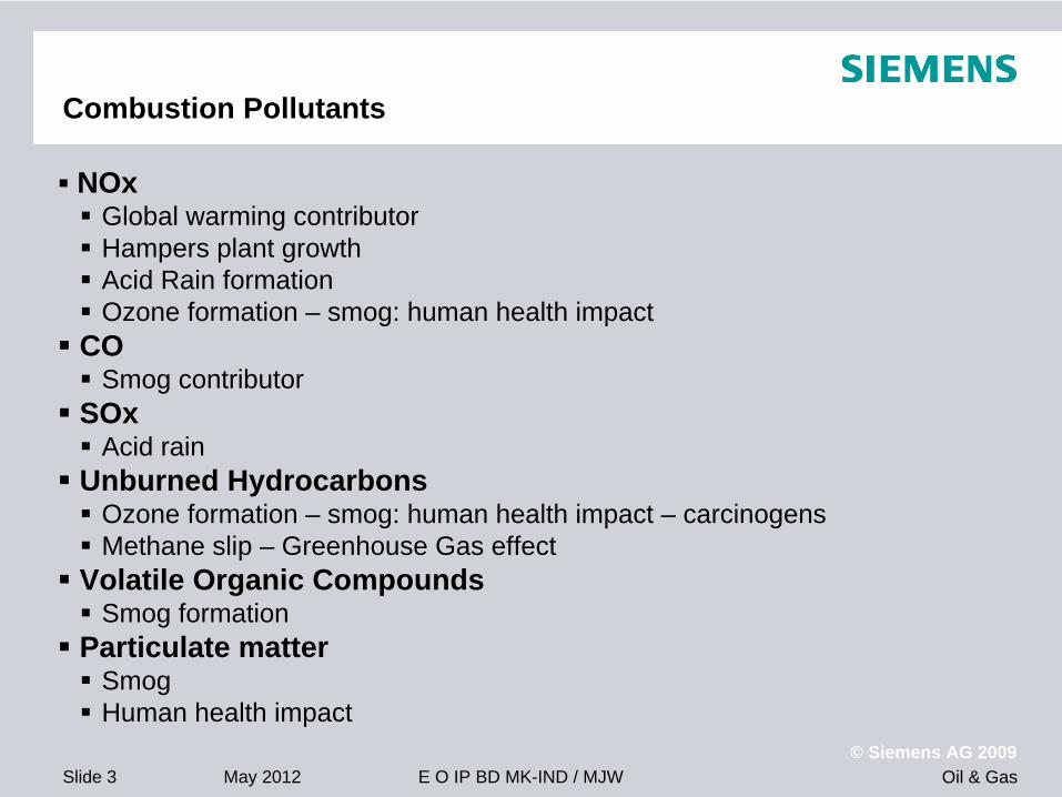
Combustion Pollutants
NOx
Global warming contributor
Hampers plant growth
Acid Rain formation
Ozone formation – smog: human health impact
CO
Smog contributor
SOx
Acid rain
Unburned Hydrocarbons
Ozone formation – smog: human health impact – carcinogens
Methane slip – Greenhouse Gas effect
Volatile Organic Compounds
Smog formation
Particulate matter
Smog
Human health impact
Oil & Gas© Siemens AG 2009
May 2012 E O IP BD MK-IND / MJWSlide 4
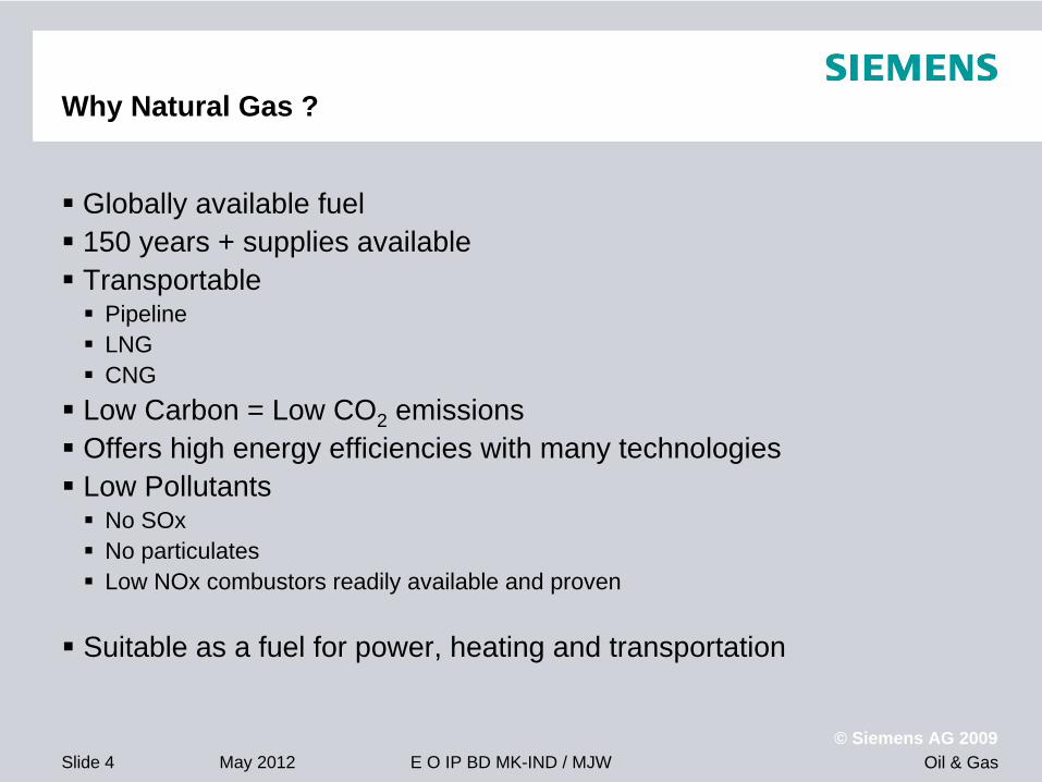
Why Natural Gas ?
Globally available fuel 150 years + supplies available Transportable
Pipeline
LNG
CNG
Low Carbon = Low CO2 emissions
Offers high energy efficiencies with many technologies
Low Pollutants
No SOx
No particulates
Low NOx combustors readily available and proven
Suitable as a fuel for power, heating and transportation
Oil & Gas© Siemens AG 2009
May 2012 E O IP BD MK-IND / MJWSlide 5
00.05
0.10.15
0.20.25
0.30.35
0.40.45
Natur
al Gas
Diesel
Coal
Lign
ite
Woo
d
MSW (n
on-B
iom
ass)
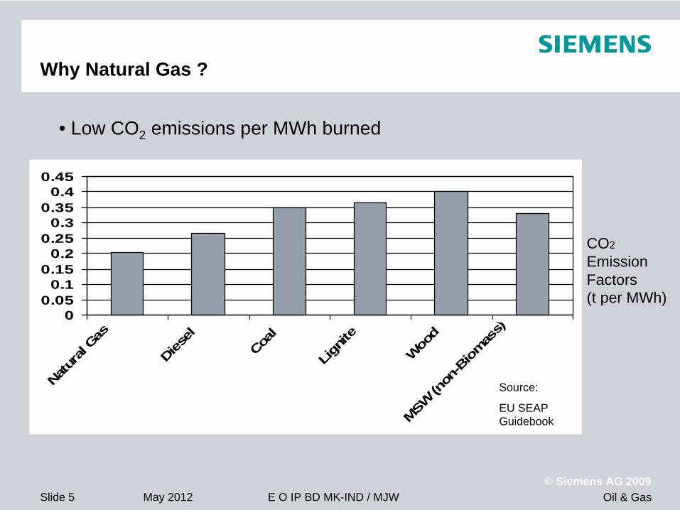
CO2
Emission Factors (t per MWh)
Source:
EU SEAP Guidebook
Why Natural Gas ?
• Low CO2 emissions per MWh burned

Oil & Gas© Siemens AG 2009
May 2012 E O IP BD MK-IND / MJWSlide 6
Gas Turbine Power Generation
How the Gas Turbine is usually perceived
• Combined Cycle
• Centralised Power Plant
• Natural Gas Fuel
• Power transmission and distribution by overhead line
• Highest efficiency for large- scale power generation
Oil & Gas© Siemens AG 2009
May 2012 E O IP BD MK-IND / MJWSlide 7
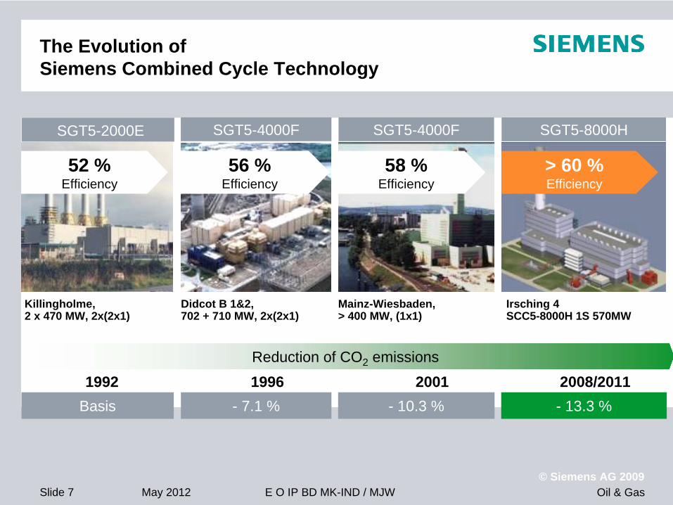
Irsching 4 SCC5-8000H 1S 570MW
> 60 %Efficiency
56 %Efficiency
Didcot B 1&2, 702 + 710 MW, 2x(2x1)
52 %Efficiency
Killingholme, 2 x 470 MW, 2x(2x1)
58 %Efficiency
Mainz-Wiesbaden,> 400 MW, (1x1)
Basis - 7.1 % - 10.3 % - 13.3 %2001 1992 1996 2008/2011
Reduction of CO2 emissions
The Evolution of Siemens Combined Cycle Technology
SGT5-4000FSGT5-2000E SGT5-8000HSGT5-4000F

Oil & Gas© Siemens AG 2009
May 2012 E O IP BD MK-IND / MJWSlide 8
Energy Efficiency
But is CCGT the best solution ?
It is one option: Offers a very high electrical efficiency Clean Requires energy to transport the gas in pipeline network
CO2 emissions
Energy losses in transmission and distribution system
Vulnerability to weather etc
Security of supply
Distributed Generation offers an alternative !

Oil & Gas© Siemens AG 2009
May 2012 E O IP BD MK-IND / MJWSlide 9
Siemens Range of Gas Turbines
State-of-the-art and innovative gas turbinesto meet today’s and tomorrow’s energy needs
13/15 Units most suitable for Distributed
Generation
47/50

Oil & Gas© Siemens AG 2009
May 2012 E O IP BD MK-IND / MJWSlide 10
Distributed Generation
Potentially offers the most energy efficient solution
Cogeneration
Utilise waste heat from Gas Turbine to produce heat (or cooling) for local consumption
Steam
Hot water
Hot air
A properly sized Cogeneration plant can achieve 80%+ overall energy efficiency
Utilise locally available fuels
Reduced transmission and distribution losses and improved security of supply
Not a new concept: Used in Oil & Gas for decades !
Oil & Gas© Siemens AG 2009
May 2012 E O IP BD MK-IND / MJWSlide 11
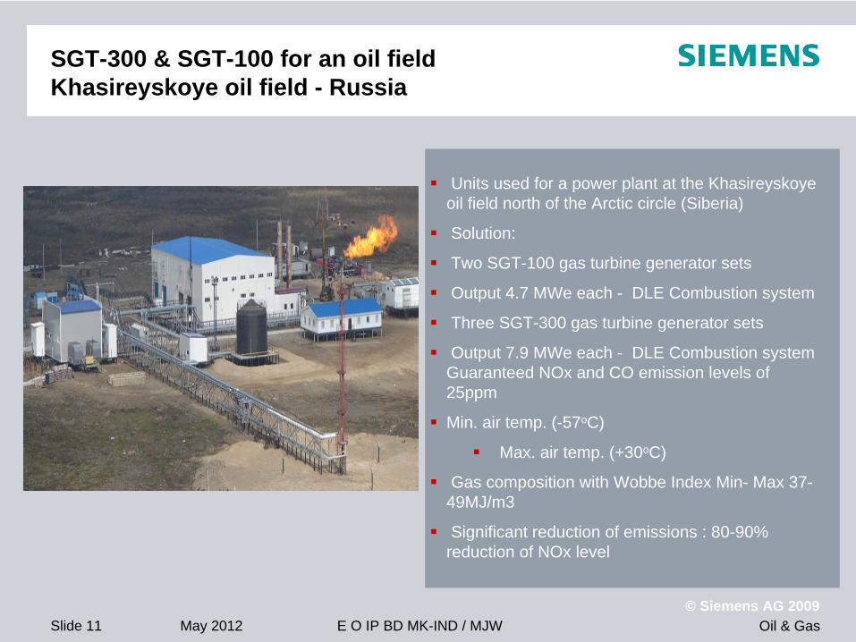
SGT-300 & SGT-100 for an oil field Khasireyskoye oil field - Russia
Units used for a power plant at the Khasireyskoye oil field north of the Arctic circle (Siberia)
Solution:
Two SGT-100 gas turbine generator sets
Output 4.7 MWe each - DLE Combustion system
Three SGT-300 gas turbine generator sets
Output 7.9 MWe each - DLE Combustion system Guaranteed NOx and CO emission levels of 25ppm
Min. air temp. (-57oC)
Max. air temp. (+30oC)
Gas composition with Wobbe Index Min- Max 37- 49MJ/m3
Significant reduction of emissions : 80-90% reduction of NOx level

Oil & Gas© Siemens AG 2009
May 2012 E O IP BD MK-IND / MJWSlide 12
• On‐site heat plus Electricity import is more efficient Fuel100% 55%
80%
Electricity
Remote CCGT Power
Plant
On-site Boiler
Steam
Losses 40%
Losses up to 20%
T&D losses circa 5%
Steam distribution losses
Fuel100%
Overall Energy Efficiency =
67.5%
The Benefits of Cogeneration
Overall Energy Balance for Remote Power Generation
Overlooks fuel mix etc. which will reduce efficiency
Oil & Gas© Siemens AG 2009
May 2012 E O IP BD MK-IND / MJWSlide 13
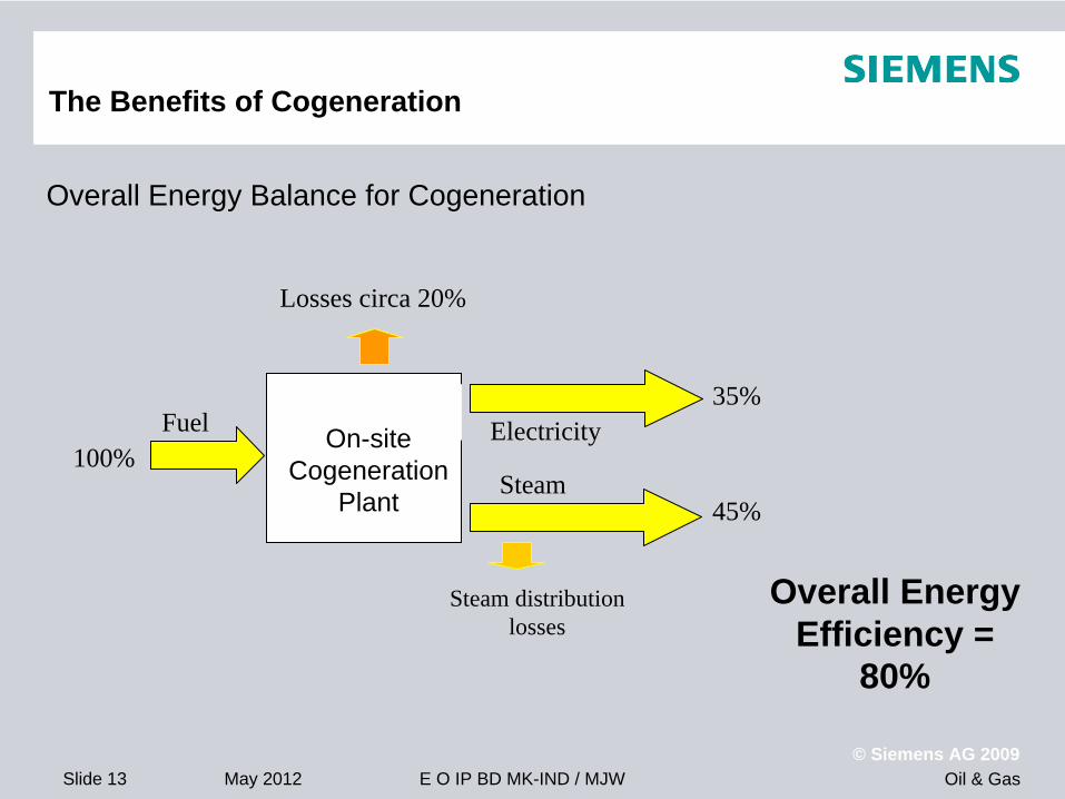
Fuel100%
35%ElectricityOn-site
Cogeneration Plant
Steam
Losses circa 20%
Steam distribution losses
45%
Overall Energy Efficiency =
80%
Overall Energy Balance for Cogeneration
The Benefits of Cogeneration

Oil & Gas© Siemens AG 2009
May 2012 E O IP BD MK-IND / MJWSlide 14
05000
1000015000200002500030000
Sepa
rate
Hea
t & P
ower
On-
site
Hea
t+
CC
GT
On-
site
Hea
t+
Mix
edPo
wer
Cog
ener
atio
n
RemoteLocal
CO2 Emissions (kg per hour)
30MW Power
40MW Heat
Local Fuel = Gas
GT = 35% eff
Boiler = 90% eff
CCGT = 60% eff
Power Mix = 40% eff
Gas = 0.056kg CO2 /MJ
Mix = 0.087kg CO2 /MJ
(Source: Natural Resources Canada)
> 10% Global CO2 Reduction over
best alternative !
The Benefits of Cogeneration

Oil & Gas© Siemens AG 2009
May 2012 E O IP BD MK-IND / MJWSlide 15
Power Generation: Gas Turbine with Cogeneration
Duct Burner (Optional)
Gas Turbine Generator
Fuel Gas
HRSG
Boiler Feed Water
Process Steam
Exhaust Stack
Unfired: Overall Energy Efficiency c. 80%
Fired: c. 90% achievable
Oil & Gas© Siemens AG 2009
May 2012 E O IP BD MK-IND / MJWSlide 16
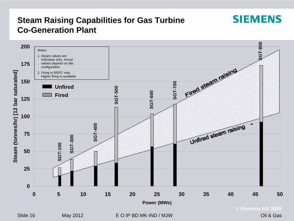
Steam Raising Capabilities for Gas Turbine Co-Generation Plant
Notes:
1. Steam values areindicative only. Actual values depend on site configuration
2. Firing to 850ºC only. Higher firing is available
0
25
50
75
100
125
150
175
200
0 5 10 15 20 25 30 35 40 45 50Power (MWe)
Stea
m (t
onne
s/hr
) [12
bar
sat
urat
ed]
UnfiredFired
SGT-
100
SGT-
300
SGT-
400
SGT-
500
SGT-
600
SGT-
700
SGT-
800
Oil & Gas© Siemens AG 2009
May 2012 E O IP BD MK-IND / MJWSlide 17
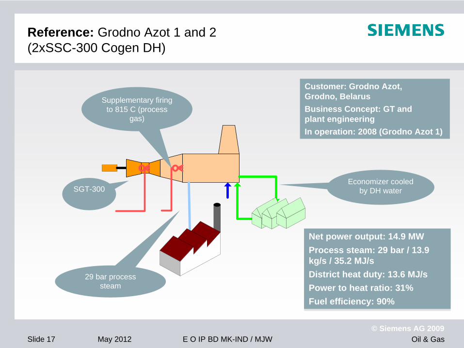
Reference: Grodno Azot 1 and 2 (2xSSC-300 Cogen DH)
Supplementary firing to 815 C (process
gas)
29 bar process steam
Economizer cooled by DH waterSGT-300
Customer: Grodno Azot, Grodno, BelarusBusiness Concept: GT and plant engineeringIn operation: 2008 (Grodno Azot 1)
Net power output: 14.9 MWProcess steam: 29 bar / 13.9 kg/s / 35.2 MJ/s District heat duty: 13.6 MJ/sPower to heat ratio: 31%Fuel efficiency: 90%
Net power output: 14.9 MWProcess steam: 29 bar / 13.9 kg/s / 35.2 MJ/sDistrict heat duty: 13.6 MJ/sPower to heat ratio: 31%Fuel efficiency: 90%
Oil & Gas© Siemens AG 2009
May 2012 E O IP BD MK-IND / MJWSlide 18
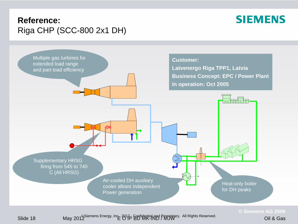
Reference: Riga CHP (SCC-800 2x1 DH)
Siemens Energy, Inc., 2012. Confidential and Proprietary. All Rights Reserved.
Supplementary HRSG firing from 545 to 740
C (All HRSG)Air-cooled DH auxiliarycooler allows independentPower generation
Heat-only boiler for DH peaks
Multiple gas turbines forextended load range and part load efficiency
Customer: Latvenergo Riga TPP1, LatviaBusiness Concept: EPC / Power PlantIn operation: Oct 2005
Oil & Gas© Siemens AG 2009
May 2012 E O IP BD MK-IND / MJWSlide 19
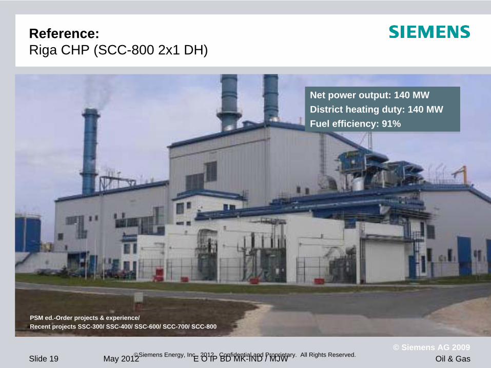
Reference: Riga CHP (SCC-800 2x1 DH)
Siemens Energy, Inc., 2012. Confidential and Proprietary. All Rights Reserved.
PSM ed.-Order projects & experience/ Recent projects SSC-300/ SSC-400/ SSC-600/ SCC-700/ SCC-800
Net power output: 140 MWDistrict heating duty: 140 MWFuel efficiency: 91%
Net power output: 140 MWDistrict heating duty: 140 MWFuel efficiency: 91%

Oil & Gas© Siemens AG 2009
May 2012 E O IP BD MK-IND / MJWSlide 20
Dry Low Emissions (DLE) Combustion
Challenge set in the 1980s by the Market to Gas Turbine manufacturers to burn fuel as efficiently but with fewer pollutants
Accepted the challenge and reduced NOx emissions to 1/5th previous levels
Introduced in 1990s, now standard combustion configuration on some models
Continued development achieving even lower emissions
Simple
Robust
No moving parts
No impact on efficiency
No impact on power output
More than 17 million operating hours achieved
High reliability and availability
Also reduced CO, UHC

Oil & Gas© Siemens AG 2009
May 2012 E O IP BD MK-IND / MJWSlide 21
Dry Low Emissions
UK Site Retrofit 3 x Dual DLE Typhoon 4.9
Relative Change in NOx Mass Emissions
0.0
20.0
40.0
60.0
80.0
100.0
120.0
Jan-
98
Feb-
98
Mar
-98
Apr
-98
May
-98
Jun-
98
Jul-9
8
Aug-
98
Sep-
98
Oct
-98
Nov
-98
Dec
-98
Jan-
99
Feb-
99
Mar
-99
Apr
-99
Months

Oil & Gas© Siemens AG 2009
May 2012 E O IP BD MK-IND / MJWSlide 22
Intelligent DLE
Provides lowest emissions through intelligent control
• Automatically identifies operating point that gives minimum NOx emissions for instantaneous site requirements
• Continuously controls fuel injection between pre-defined limits of temperature and combustor pressure dynamics
• Operation independent of load and fuel composition
• No external instrumentation required
• Dual Fuel (Gas / Liquid) or Gas only operation
• Tri-fuel operation proven (natural gas, lean gas, distillate fuel)
Available on SGT-100 through SGT-400
Oil & Gas© Siemens AG 2009
May 2012 E O IP BD MK-IND / MJWSlide 23
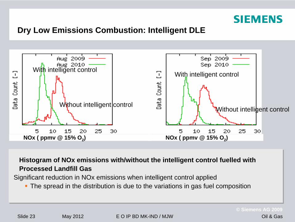
Dry Low Emissions Combustion: Intelligent DLE
Histogram of NOx emissions with/without the intelligent control fuelled with Processed Landfill Gas
Significant reduction in NOx emissions when intelligent control applied
The spread in the distribution is due to the variations in gas fuel composition
Histogram of NOx emissions with/without the intelligent control fuelled with Processed Landfill Gas
Significant reduction in NOx emissions when intelligent control applied
The spread in the distribution is due to the variations in gas fuel composition
Without intelligent control
With intelligent control
Without intelligent control
With intelligent control
NOx ( ppmv @ 15% O2 ) NOx ( ppmv @ 15% O2 )

Oil & Gas© Siemens AG 2009
May 2012 E O IP BD MK-IND / MJWSlide 24
Fuel Flexibility
Gas turbines can run on a wide
variety of fuels
DLE combustion
Lean gases (high N2 or CO2 content)
Wellhead gases, landfill gas, digester gas
Rich gases (high HC content)
Wellhead gases, process offgas
Diesel or kerosene
More usual as stand-by fuels
Conventional combustion
High hydrogen gases
LPG and naphtha
Crude oil
10 7040
Lean Gases Rich Gases‘Pipeline’ Quality
Wobbe Index (MJ/Nm3)
Siemens solution available
Time [minutes]
N2
co
nte
nt
[wt%
] an
d N
Ox
[pp
m]
50403020100
60
50
40
30
20
10
0
25
20
15
10
5
0
N2NOxComb DynLoad
Co
mb
ust
ion
Dyn
amic
s [%
of
larm
leve
l]
Load
[MW
]

Oil & Gas© Siemens AG 2009
May 2012 E O IP BD MK-IND / MJWSlide 25
High Power, Small Footprint
One feature of a modern Light
Industrial Gas Turbine is its high power density
Light weight
Compact
Low vibrations
Modular assemblies
Makes them ideal for installations:
Offshore Platforms
Restricted space
Transportation / site erection constraints
Mobile and transportable units
SGT-400 14.4MW Generator Set:
14.2 m x 3.1m 129 Tonnes
SGT-750 35.9MW Generator Set:
20.3 m x 4.8m
Oil & Gas© Siemens AG 2009
May 2012 E O IP BD MK-IND / MJWSlide 26
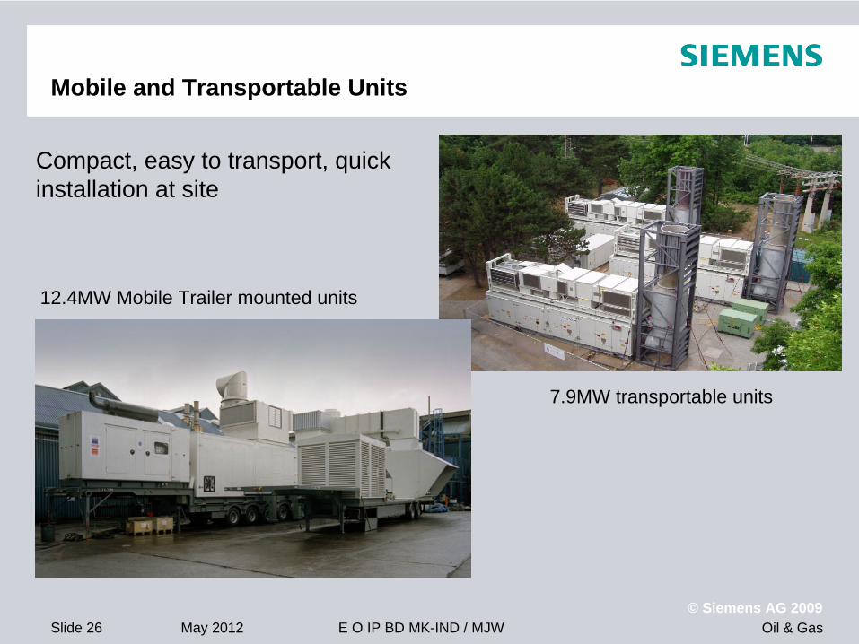
Mobile and Transportable Units
12.4MW Mobile Trailer mounted units
7.9MW transportable units
Compact, easy to transport, quick installation at site

Oil & Gas© Siemens AG 2009
May 2012 E O IP BD MK-IND / MJWSlide 27
Power generation barge module 4x47MW / 188 MW ISO
4xSGT800 single lift packages in barge or module design
Volga–Don canal adopted
95x16 meters
12 meters transport height

Oil & Gas© Siemens AG 2009
May 2012 E O IP BD MK-IND / MJWSlide 28
Modularized CCPP concept
ACC modulesE&C module
ACC module
ST tail module
ST module
Oil cooler modules
GT modulesPipe rack modules
HRSG modules
Feed water module
GT E&C modules

Oil & Gas© Siemens AG 2009
May 2012 E O IP BD MK-IND / MJWSlide 29
Modularized CCPP, for on-offshore installations
Off-shore installation with 4xSCC-800 3x1C, modularized concept

Oil & Gas© Siemens AG 2009
May 2012 E O IP BD MK-IND / MJWSlide 30
Summary
Gas Turbines offer:
Flexibility in configuration
High Energy Efficiencies achievable leading to reduced GHG emissions
High Electrical efficiency in Combined Cycle
High Overall energy efficiency in Cogeneration
Flexibility in fuel choices
Low combustion emissions
Flexibility in Location

Oil & Gas© Siemens AG 2009
May 2012 E O IP BD MK-IND / MJWSlide 31
Any Questions?
Thank you for your attention