Embed Size (px)
Citation preview

CONFIDENTIAL. This document contains trade secret information. Disclosure, use or reproduction outside Cargill or inside Cargill, to or by those employees who do not have a need to know is prohibited except as authorized by Cargill in writing.
Envirotemp ™ FR3™
NWPPA E&O ETF MeetingSpokane, Wa.
April 11, 2016
www.cargill.com
Natural Ester
Dielectric Fluid
Overview
Jeff Valmus
• Natural ester (dielectric fluid) insulating liquid is made
from the oil of naturally grown vegetables
• Several different varieties have been made but the most
widely used is FR3 which is made from soybean oil
• Initially designed to be an environmentally friendly
alternative to less flammable dielectric fluids like PCBs
and High Molecular Weight Hydrocarbons
• Commercially began using in transformers in 19968
What is Natural Ester Dielectric Fluid?
2
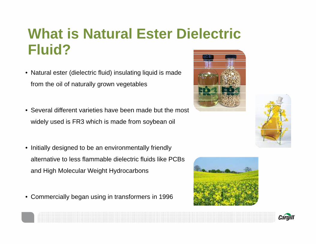
Validated by industry
Meets IEEE and IEC standards- More than 250 series of tests
conducted on FR3 fluid- IEEE C57.154 and IEC 60076-14
High temperature insulation system standard enables up to 85 rise new transformer designs
Classified as a less flammable fluid (K-class)
- Underwriters Laboratory - FM Global
Environmental testing- Carbon neutral according to BEES 4.0
lifecycle analysis- Ultimately biodegradable by EPA- Non-toxic and non-hazardous in soil and
water by OECD
Industry recognition- 2013 Presidential Green Chemistry Award- 2013 EPA Design for the Environment (DfE)
designation (SaferChoice label)- USDA BioPrefered Program- EPA Environmental Technology Verification
California Environmental Technology Certification
- FERC ruling – Retrofills with FR3 fluid may be capitalized
3 Cargill FR3™ fluid overview

Over 1,000,000 natural ester fluid-filled transformers in service globally
− 25,000 medium & large power transformers
− 15,000 indoor units
− 50,000 substations
− 10,000 retrofills
FR3 fluid approved for transformers up to 500kV¯ HV testing validates usage through 500kV¯ Siemens 420kV loaded in 2013, Germany¯ 500kV transmission line for Electronorte,
Brazil¯ 345KV transmission line for Bureau of
Reclamation, US
Over 100 utilities, including many complete adapters
- PGE, EWEB, SCL, PG&E, SMUD, etc.
- Many Munis, Coops, and RECs
Over 100 global OEMs applying and promoting technology
Types of installations− Industrial/Commercial − Utility − Network transformers− New and retrofill applications
Proven, global installations
10
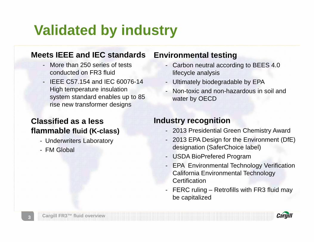
How are Natural Esters different from mineral oil
• Fire safety
• No fires, cleanup, downtime, or replacement costs• Protects nearby equipment and buildings• Greatly reduced risk to personnel • Reduced clearance requirements and preventative equipment
• Optimized transformer performance
• Insulation system up to 8X* extended lifespan• Transformer asset extended lifespan• Increased overload capability• Enables smaller, lighter (75-85C rise) designs
• Environmental
• FR3 fluid produced from domestic soybeans • Environmental safety (no hazardous fumes, fires, reduced
spill mitigation)• Petroleum independent• Reduced carbon emissions• Biodegradable/non-toxic, recyclable, and sustainable
5
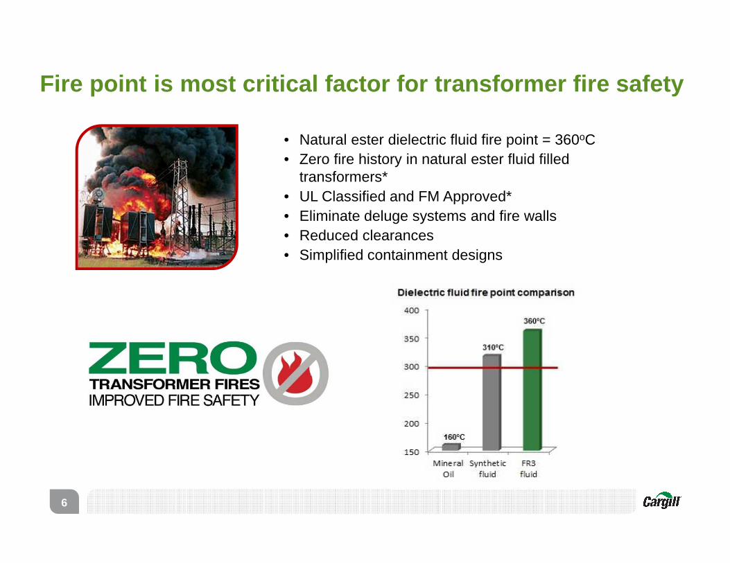
• Natural ester dielectric fluid fire point = 360oC• Zero fire history in natural ester fluid filled
transformers*• UL Classified and FM Approved*• Eliminate deluge systems and fire walls• Reduced clearances • Simplified containment designs
6
Fire point is most critical factor for transformer fire safety

Fire wall
Natural ester simplified
borderMineral oil
containment and suppression rocks
Mineral oil transformerNatural ester fluid transformer
Automatic fire suppression
system
Building
Reduced clearance
7

Simpler containment systemTypical Containment system for Mineral Oil
Designed to 110% of larger equipment oil volume + rain water + fire fighting system water, automatic or manual
Rocks for flame suppresion
SumpOil + Rocks volume
Oil / Water separation tank
Simplified sump proposed forEnvirotemp FR3 (if required)
Designed for larger equipment oil volume + rain water
Manual or Automatic draining system
Fluid volume + rain water
8

Natural ester fluid is a better c hoice for the communities you serve
9
• Made from a renewable resource- >98% vegetable oil
- Carbon neutral*
- Contains no petroleum, halogens, silicones or sulfurs
• Non-toxic, non-hazardous in water and soil- OECD oral and aquatic toxicity test
• Biodegrades in 28 days or less - Ultimately biodegradable according Environmental Protection Agency (EPA)
• Recyclable and Sustainable
* According to BEES 4.0 lifecycle analysis

Biodegradable
Non-toxic
FR3 fluid is biodegradable and non-toxic on both soil and water.
Best-in -class environmental properties
10
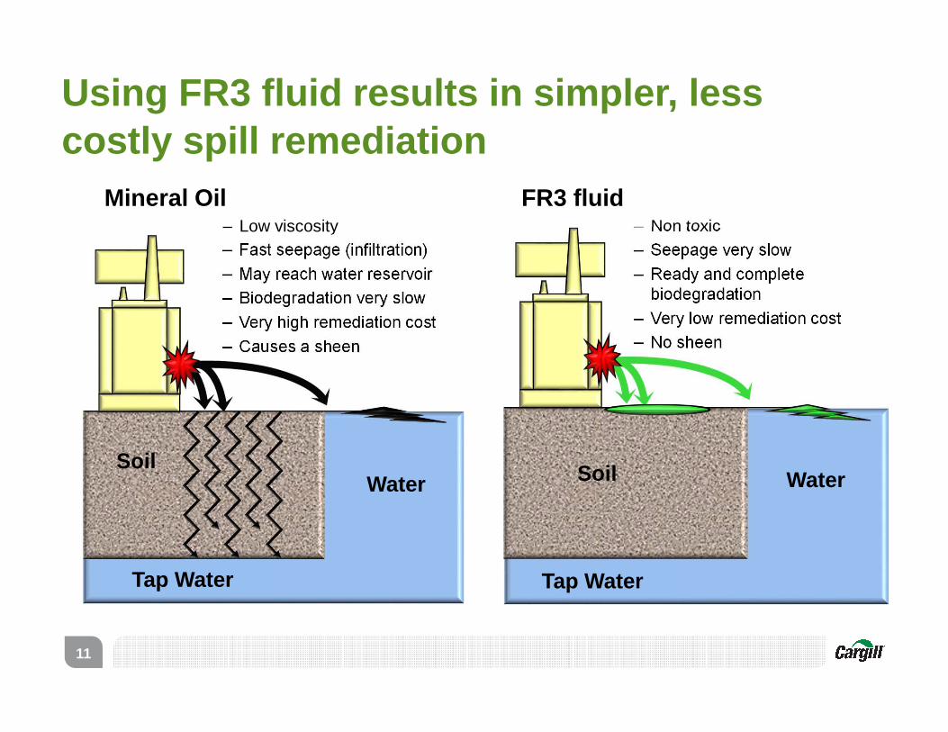
Using FR3 fluid results in simpler, less costly spill remediation
11
Mineral Oil– Low viscosity– Fast seepage (infiltration)– May reach water reservoir – Biodegradation very slow– Very high remediation cost– Causes a sheen
WaterSoil
Tap Water
FR3 fluid– Non toxic– Seepage very slow– Ready and complete
biodegradation– Very low remediation cost– No sheen
WaterSoil
Tap Water
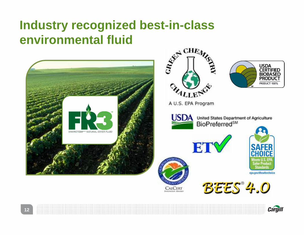
Industry recognized best-in -class environmental fluid
12

Transformer Design and Operational Optimization
13

Improve reliability: Extend insulation and asset life 5 -8x longer than mineral oil
Unique chemistry of FR3™ fluid protects insulating paper by:
• oil
14
• Hydrolysis of natural ester “consumes” the water and produces fatty acids. This process removes dissolved water
• FR3™ Fluid is in essence ‘self drying.’ Water concentrations in the fluid will be reduced due to hydrolysis over time.
• FR3 fluid can absorb significantly more water than mineral oil
• FR3 fluid has 10 times the water saturation (PPM) than mineral
Protecting life of insulation paper is the number one factor that determines asset life
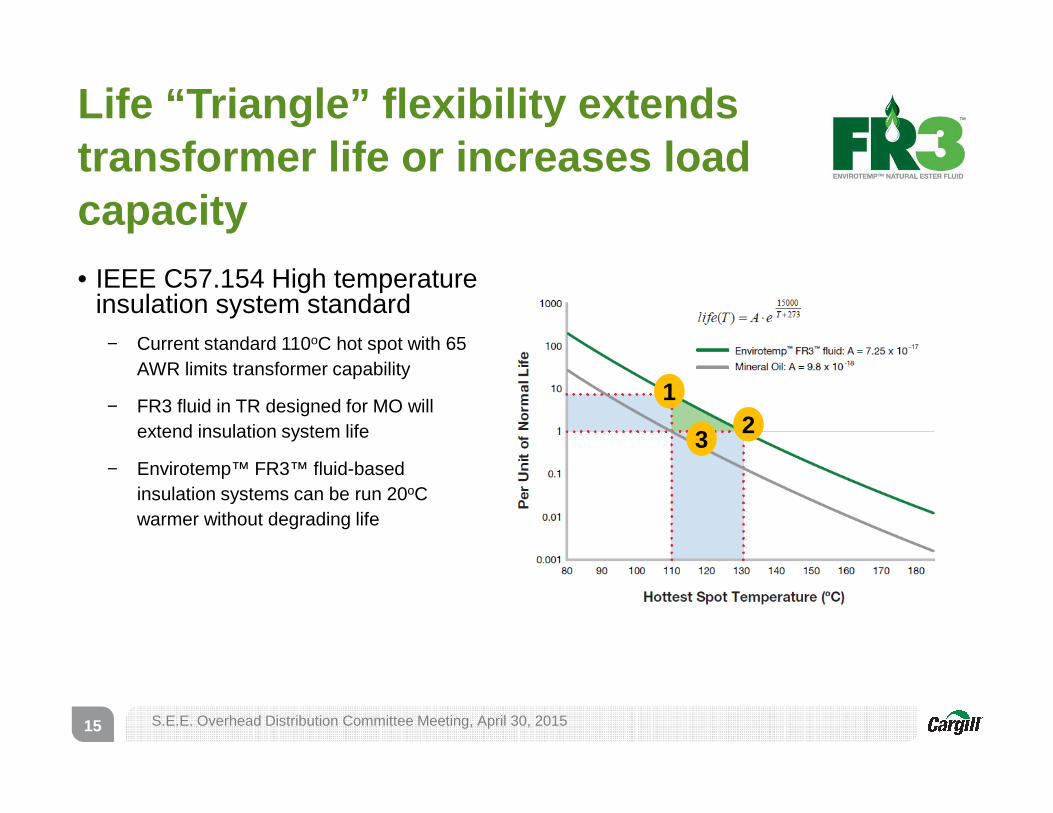
Life “Triangle” flexibility extends transformer life or increases load capacity
15
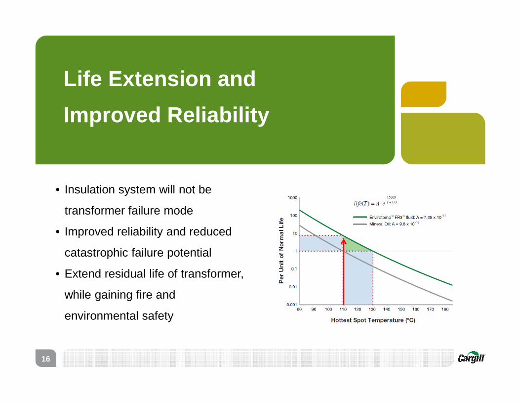
• IEEE C57.154 High temperature insulation system standard
− Current standard 110oC hot spot with 65 AWR limits transformer capability
− FR3 fluid in TR designed for MO will extend insulation system life
− Envirotemp™ FR3™ fluid-based insulation systems can be run 20oC warmer without degrading life
S.E.E. Overhead Distribution Committee Meeting, April 30, 2015
1
32
Life Extension and
Improved Reliability
• Insulation system will not be
transformer failure mode
• Improved reliability and reduced
catastrophic failure potential
• Extend residual life of transformer,
while gaining fire and
environmental safety
16
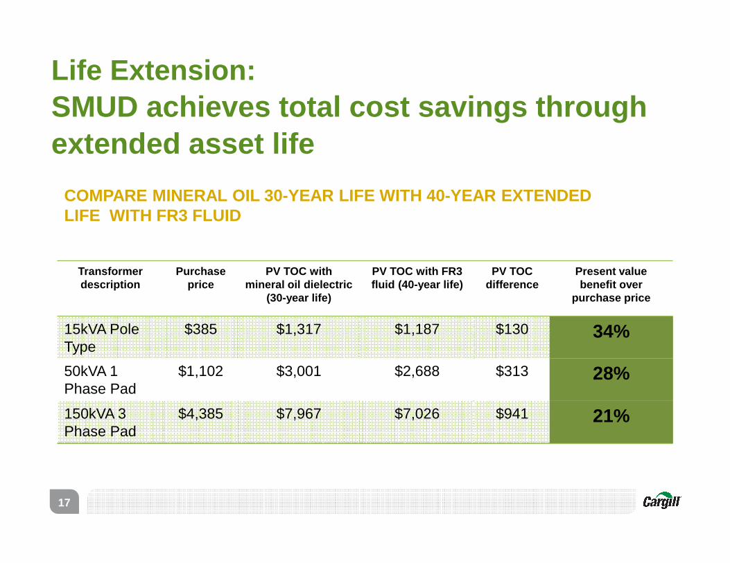
Life Extension:SMUD achieves total cost savings through extended asset life
17
Transformer description
Purchase price
PV TOC with mineral oil dielectric
(30-year life)
PV TOC with FR3 fluid (40-year life)
PV TOCdifference
Present value benefit over
purchase price
15kVA Pole Type
$385 $1,317 $1,187 $130 34%
50kVA 1 Phase Pad
$1,102 $3,001 $2,688 $313 28%
150kVA 3 Phase Pad
$4,385 $7,967 $7,026 $941 21%
COMPARE MINERAL OIL 30-YEAR LIFE WITH 40-YEAR EXTEN DED LIFE WITH FR3 FLUID
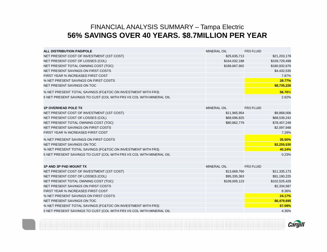
ALL DISTRIBUTION PAD/POLE MINERAL OIL FR3 FLUID
NET PRESENT COST OF INVESTMENT (1ST COST) $25,635,713 $21,203,178
NET PRESENT COST OF LOSSES (COL) $164,032,188 $159,729,498
NET PRESENT TOTAL OWNING COST (TOC) $189,667,902 $180,932,676
NET PRESENT SAVINGS ON FIRST COSTS $4,432,535
FIRST YEAR % INCREASED FIRST COST 7.87%
% NET PRESENT SAVINGS ON FIRST COSTS 28.77%NET PRESENT SAVINGS ON TOC $8,735,226
% NET PRESENT TOTAL SAVINGS (FC&TOC ON INVESTMENT WITH FR3) 56.70%
5 NET PRESENT SAVINGS TO CUST (COL WITH FR3 VS COL WITH MINERAL OIL 2.62%
1P OVERHEAD POLE TX MINERAL OIL FR3 FLUID
NET PRESENT COST OF INVESTMENT (1ST COST) $11,965,954 $9,868,006
NET PRESENT COST OF LOSSES (COL) $68,696,825 $68,539,242
NET PRESENT TOTAL OWNING COST (TOC) $80,862,779 $78,407,248
NET PRESENT SAVINGS ON FIRST COSTS $2,097,948
FIRST YEAR % INCREASED FIRST COST 7.29%
% NET PRESENT SAVINGS ON FIRST COSTS 35.50%
NET PRESENT SAVINGS ON TOC $2,255,530% NET PRESENT TOTAL SAVINGS (FC&TOC ON INVESTMENT WITH FR3) 40.24%
5 NET PRESENT SAVINGS TO CUST (COL WITH FR3 VS COL WITH MINERAL OIL 0.23%
1P AND 3P PAD MOUNT TX MINERAL OIL FR3 FLUID
NET PRESENT COST OF INVESTMENT (1ST COST) $13,669,760 $11,335,173
NET PRESENT COST OF LOSSES (COL) $95,335,363 $91,190,225
NET PRESENT TOTAL OWNING COST (TOC) $109,005,123 $102,525,428
NET PRESENT SAVINGS ON FIRST COSTS $2,334,587
FIRST YEAR % INCREASED FIRST COST 8.36%
% NET PRESENT SAVINGS ON FIRST COSTS 24.17%NET PRESENT SAVINGS ON TOC $6,479,695
% NET PRESENT TOTAL SAVINGS (FC&TOC ON INVESTMENT WITH FR3) 67.09%
5 NET PRESENT SAVINGS TO CUST (COL WITH FR3 VS COL WITH MINERAL OIL 4.35%
FINANCIAL ANALYSIS SUMMARY – Tampa Electric56% SAVINGS OVER 40 YEARS. $8.7MILLION PER YEAR

Overload Capability
• Existing transformer
land-locked (footprint)?
• At or above rated load?
• Ability to handle
increased load with
same equipment
19
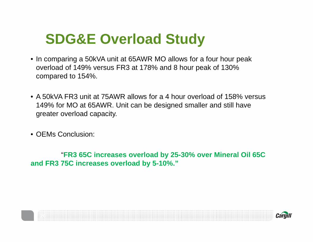
SDG&E Overload Study
20
• In comparing a 50kVA unit at 65AWR MO allows for a four hour peak overload of 149% versus FR3 at 178% and 8 hour peak of 130% compared to 154%.
• A 50kVA FR3 unit at 75AWR allows for a 4 hour overload of 158% versus 149% for MO at 65AWR. Unit can be designed smaller and still have greater overload capacity.
• OEMs Conclusion:
“FR3 65C increases overload by 25-30% over Mineral O il 65C and FR3 75C increases overload by 5-10%.”
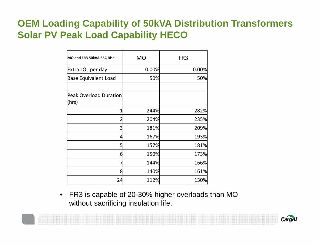
OEM Loading Capability of 50kVA Distribution Transf ormers Solar PV Peak Load Capability HECO
21
MO and FR3 50kVA 65C Rise MO FR3
Extra LOL per day 0.00% 0.00%
Base Equivalent Load 50% 50%
Peak Overload Duration
(hrs)
1 244% 282%
2 204% 235%
3 181% 209%
4 167% 193%
5 157% 181%
6 150% 173%
7 144% 166%
8 140% 161%
24 112% 130%
• FR3 is capable of 20-30% higher overloads than MO without sacrificing insulation life.
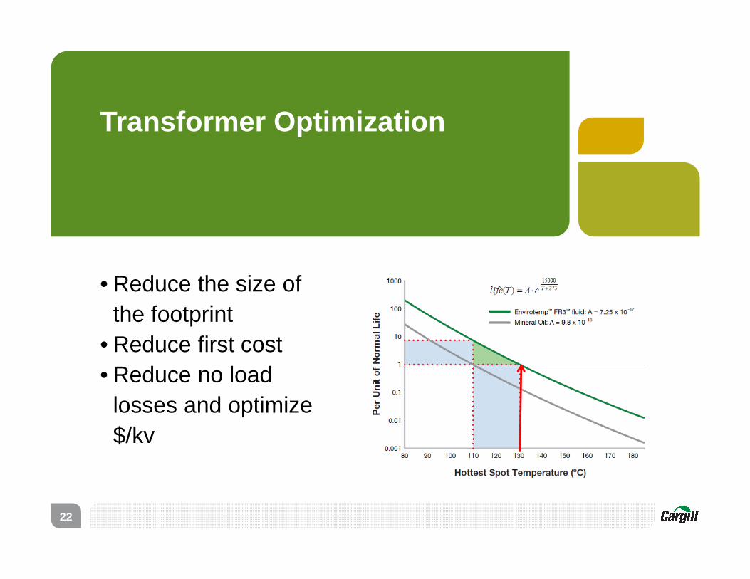
Transformer Optimization
• Reduce the size of the footprint
• Reduce first cost• Reduce no load
losses and optimize $/kv
22
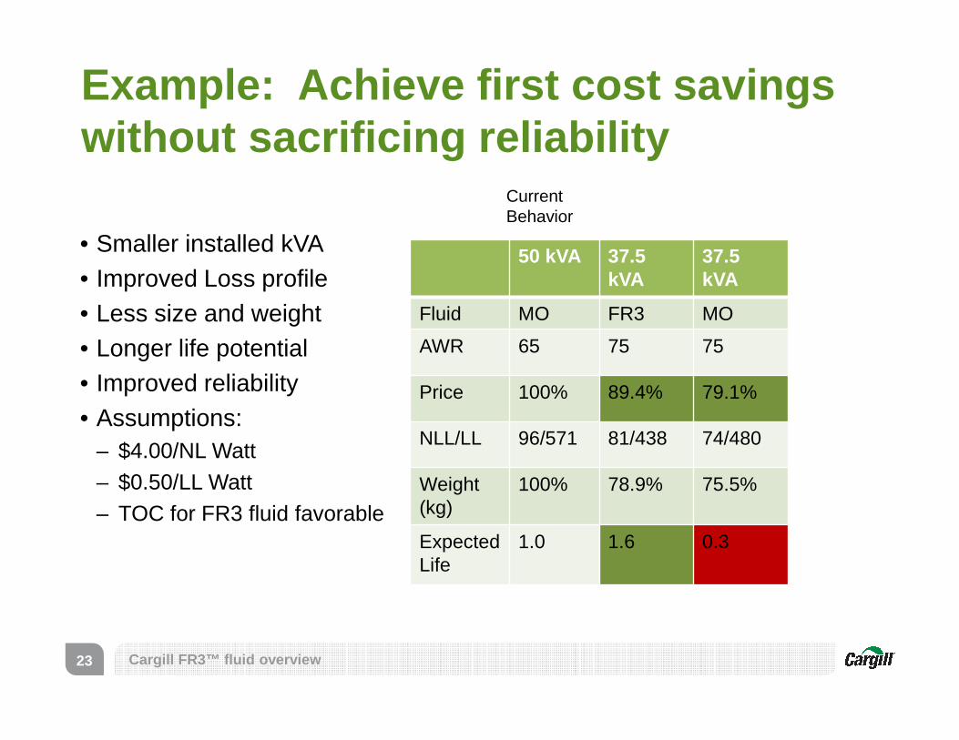
Example: Achieve first cost savings without sacrificing reliability
50 kVA 37.5 kVA
37.5 kVA
Fluid MO FR3 MO
AWR 65 75 75
Price 100% 89.4% 79.1%
NLL/LL 96/571 81/438 74/480
Weight (kg)
100% 78.9% 75.5%
ExpectedLife
1.0 1.6 0.3
23
• Smaller installed kVA• Improved Loss profile• Less size and weight• Longer life potential• Improved reliability• Assumptions:
– $4.00/NL Watt– $0.50/LL Watt– TOC for FR3 fluid favorable
Current Behavior
Cargill FR3™ fluid overview

Total Owning Cost v. Loading
$0.00
$500.00
$1,000.00
$1,500.00
$2,000.00
$2,500.00
$3,000.00
25% 50% 75% 100% 125% 150% 175%
37.5 FR3 65 C
50 M 65 C
37.5 FR3 75 C
Loading
TOC
MO 100% Load = 1.0 (Service Life approx. 20 years)
FR3 100% Load @ 65C= 7.4X MO Life
FR3 100% Load @ 75C= 3.2X MO Life
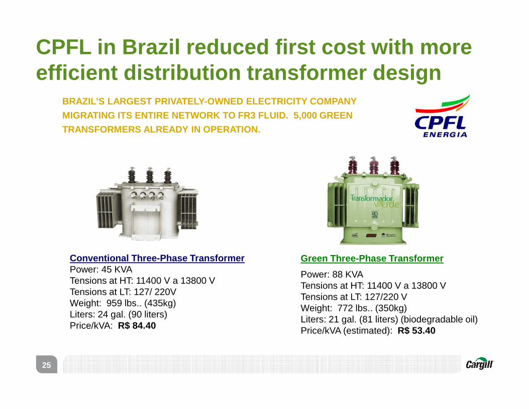
CPFL in Brazil reduced first cost with more efficient distribution transformer design
25
Conventional Three-Phase TransformerPower: 45 KVATensions at HT: 11400 V a 13800 VTensions at LT: 127/ 220VWeight: 959 lbs.. (435kg)Liters: 24 gal. (90 liters)Price/kVA: R$ 84.40
Green Three-Phase Transformer
Power: 88 KVATensions at HT: 11400 V a 13800 VTensions at LT: 127/220 VWeight: 772 lbs.. (350kg)Liters: 21 gal. (81 liters) (biodegradable oil)Price/kVA (estimated): R$ 53.40
BRAZIL’S LARGEST PRIVATELY-OWNED ELECTRICITY COMPAN Y
MIGRATING ITS ENTIRE NETWORK TO FR3 FLUID. 5,000 G REEN
TRANSFORMERS ALREADY IN OPERATION.

In Conclusion:
Natural Ester Dielectric Fluid
26
• Prevents fires from occurring in operating transformers
• Is environmentally friendly, renewable, recyclable and sustainable
• Is applicable for new and retrofill transformers and voltage regulators
• Provides for extended life and a lower overall cost with positive NPV
• Allows for smaller kVA installation with lower losses and initial costs
• Overload capability without additional loss of life

Thank You
27

Appendix
28
Fluid Comparison
29

Dielectric fluid comparison
30
Mineral Oil Natural Ester Synthetic Ester Silicone Oil
Diagnostic Capability
Yes Yes Yes Less
Fire point 160oC 360oC 310oC 340oC
Biodegradability No Ultimately Readily No
Toxicity Toxic Non-toxic Less toxic Toxic
Biobased No Yes No No
Oxidation Good Limited (non-free breathing)
Good Good
Aging Average Best Better Average
Cost $ $$ $$$ $$
Fluid differences impact performance
31
FluidCharacteristics
Mineral Oil FR3™ Fluid
Transformer performance
65 AWR
110ºC hottest spot
85 AWR
130ºC hottest spot
Allows for overload or life extension
Reliability-dielectric strength
Dielectric strength declines as heat increases due towater saturation
Ability to hold 10 times more water
Retains dielectric strength as heat increases
Self Drying
Hydrolysis “consumes” the water
Fire safety Flash point 155ºC
Fire point 160ºC
Flash point 330ºC
Fire point 360ºC
Environmental footprint
Non-biodegradable Costly spill remediation
Non toxic, non-hazardous in soil and water
Carbon neutral
Biodegradable in 28 days
Field experience 120 years of fieldexperience
20 years of field experience
SPCAA Presentation – May 13, 2014
Technology Comparative Summary
MINERAL OIL• Low Temperatures • Diagnostic Testing Capability• Fires when happen major hazard• Fire Hazard in Sensitive Areas• Increasing Environmental Regulation• Instability of Supply & Price• Lowest Cost
CAST RESIN DRY TYPE• Main use Indoor Locations (susceptible to
dirt/moisture) • Higher Temperatures & Losses • Sensitive to Overload & Harmonics• Regular Cleaning Required• Minimal Diagnostic Testing• Service Life Concerns• Large size• Highest Initial & Operating Cost
SILICONE• Good Fire Safety & Overall Reliability • Low Temperature• Not above 36kV• Less Diagnostic Testing Capability• Inferior Coolant & Dielectric• Not Suitable as Switching Medium • Not Biodegradable• Higher Cost
NATURAL ESTER (FR3 FLUID)• 100% Fire Safety • Readily Biodegradable• Sustainable, Renewable Supply• Superior Moisture Tolerance• Extends solid insulation lifespan• Sealed transformer only• Diagnostic testing capability• Higher cost
SYNTHETIC ESTER• 100% Fire Safety• Readily Biodegradable• Best Moisture Tolerance• Low Temperature • Superior Oxidation resistance• Diagnostic testing capability• Applicable in true free-breathing
transformers• Highest Cost
FR3 fluid -filled transformer advantages versus dry -type transformers
• Lower noise
• Lower temperature
• Higher efficiency
• Longer life
• Higher over loadability
• Higher BIL
• Full diagnostic capability
• Contamination resistance
• Improved fire safety
• Smaller footprint
• Lower initial price
Dry type transformers do burn!
3333
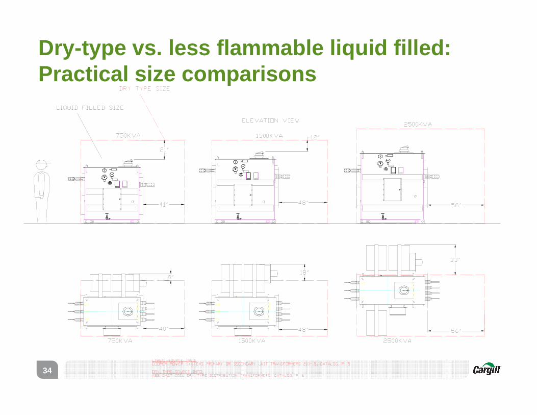
Dry-type vs. less flammable liquid filled: Practical size comparisons
34

2500 kVA transformer
� Transformer energy efficiency is determined by dividing its nameplate rating by the sum of its nameplate rating plus its total losses
� A small difference in energy efficiency can be significant when valued over the life of the transformer
Comparative transformer performanceEFFICIENCY
35

Liquid Cast Dry
Total Losses @ 50% Load (kW): 6.76 12.18 12.25
kW⋅h Billing Rate: x $0.06 $0.06 $0.06
Annual Hours: x 8760 8760 8760
Cost of Energy for Losses: = $3,553 $6,402 $6,439
Excess Annual Energy Costs: Base $2,849 $2,886
10-Yr* Excess Energy Costs: Base $28,488 $28,855
ALSO: transformers losses are dissipated as heat, w hich must be removed from a controlled temperature environment by air conditioning. For both examples the 10-year air conditioning cost difference is
~$14,000
Comparative transformer performanceEFFICIENCY
36

History
37

• Natural ester insulating liquid• Vegetable Oil¯ A wide variety available
¯ Not all “edible”¯ Biobased, sustainable supply¯ Key is to find balance between properties
8
What Is Envirotemp™ FR3™ fluid?

39
FR3 Fluid Formulation Developed
ASTM Standard Published
Envirotemp Dielectric Fluids Business Purchased by Cargill
19Jun12
FR3 Fluid Applied to 1st Transformer
FR3 Fluid Commercially Available
IEC Standard Published
IEEE Standard Published
High Temp Insulation System Standards Published
1990
1995
2000
2005
2010
2015DGA Standard Published
FR3 fluid timeline

Free Breathing Designs
Sealed Designs
Thermally Upgraded
Kraft
Natural Esters
1880 1900 1930 1960 1990 2010
Common failure mode: mineral oil (sludge, a bi-product of oxidation) impacted heat transfer/dissipation
Diagnostics put into practice
2020
High temperature materials standards
Common failure mode: shifted to solid insulation; constrained by operating temperature
Common failure mode: solid insulation; operating temperature increased
85oC AWR, 130oC HST55oC AWR, 95oC HST 65oC AWR, 110oC HST
Common failure mode: solid insulation; operating temperature increased
Transformer history (1890-present)

Dielectric Fluid Functions:1. Electrical Insulator2. Coolant�Diagnostic capabilities
41
Dielectric Fluid(fills inside of tank)
Dielectric fluid is used inside of transformers
Hottest Spot
Temperature
(℃)
Average
Winding Rise (K)
(Top Temp - Bottom
Temp)/2
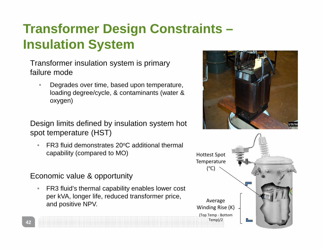
Transformer insulation system is primary failure mode
• Degrades over time, based upon temperature, loading degree/cycle, & contaminants (water & oxygen)
Design limits defined by insulation system hot spot temperature (HST)
• FR3 fluid demonstrates 20oC additional thermal capability (compared to MO)
Economic value & opportunity
• FR3 fluid’s thermal capability enables lower cost per kVA, longer life, reduced transformer price, and positive NPV.
42
Transformer Design Constraints –Insulation System

Standards
43
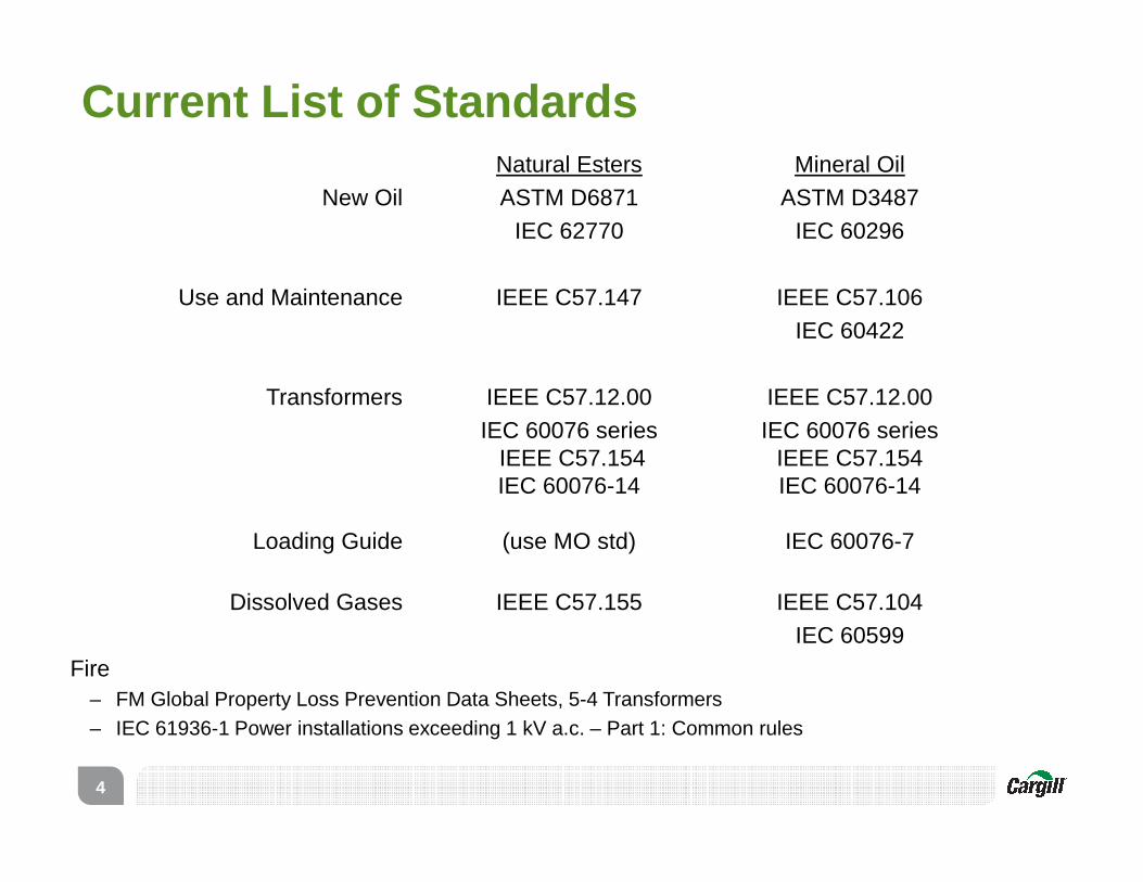
Natural Esters Mineral OilNew Oil ASTM D6871 ASTM D3487
IEC 62770 IEC 60296
Use and Maintenance IEEE C57.147 IEEE C57.106IEC 60422
Transformers IEEE C57.12.00 IEEE C57.12.00IEC 60076 series IEC 60076 series
IEEE C57.154 IEEE C57.154IEC 60076-14 IEC 60076-14
Loading Guide (use MO std) IEC 60076-7
Dissolved Gases IEEE C57.155 IEEE C57.104IEC 60599
Fire– FM Global Property Loss Prevention Data Sheets, 5-4 Transformers– IEC 61936-1 Power installations exceeding 1 kV a.c. – Part 1: Common rules
Current List of Standards
4

Table 2a. Separation Distance Between Outdoor Liquid Insulated Transformers and Buildings
LiquidApproved Transformer
or EquivalentLiquid Volume
gal (m3)
Two Hour Fire Resistant Construction
ft (m)
Noncombustible Construction
ft (m)
Combustible Construction ft
(m)
Vertical Distance ft
(m)Yes N/A 5 (1.5)
≤ 10,000 (38) 25 (7.6) 25 (7.6)> 10,000 (38) 50 (15.2) 50 (15.2) < 500 (1.9) 5 (1.5) 15 (4.6) 25 (7.6) 25 (7.6)
500-5,000 (1.9-19) 15 (4.6) 25 (7.6) 50 (15.2) 50 (15.2)> 5,000 (19) 25 (7.6) 50 (15.2) 100 (30.5) 100 (30.5)
1) All transformer components must be accessible for inspection and maintenance.
Table 2b. Outdoor Fluid Insulated Transformers Equipment Separation Distance1
LiquidApproved Transformer
or EquivalentLiquid Volume
gal (m3) Distance ft (m)Yes N/A 3 (0.9)
≤ 10,000 (38) 5 (1.5)> 10,000 (38) 25 (4.6) < 500 (1.9) 5 (1.5)
500-5,000 (1.9-19) 25 (4.6)> 5,000 (19) 50 (7.6)
1) All transformer components must be accessible for inspection and maintenance.
Mineral Oil (or unapproved fluid)
N/Adistance from containment
edge
Less Flammable (Approved Fluid)
distance from transformerNo
distance from transformer
distance from containment
edge
Less Flammable (Approved Fluid)
Mineral Oil (or unapproved fluid)
No
N/A
Horizontal Distance1
3 (0.9)5 (1.5)
15 (4.6)
Fire safety : FM Global risk mitigation
45
FR3 fluid in application
46

BASED ON THE PERFORMED TESTS AND SEVERAL PUBLISHED PAPERS, SEVERAL CONCLUSIONS CAN BE MADE:
Envirotemp FR3 Fluid
Mineral Oil
Transformer Designturn-to-turn = =coil-to-coil = =
bushing-to-tank wall = =creep = =
tap changer selector rod = =In-Service
water contamination +++ ---particulate
contaminationcellulose ++ --
copper + -streaming electrification ++ --
bubble formation +++ ---+ better = the same – worse
Envirotemp FR3 Fluid
Mineral Oil
Electrode Geometry – Oil Gap
uniform = =
mildly divergent = =
strongly divergent - +
Electrode Geometry –Creep
mildly divergent = =
strongly divergent - +
FR3 fluid has equivalent or superior dielectric strength to mineral oil
47

LIST BELOW SHOWS MATERIALS TESTED AND APPROVED WITH FR3 FLUID
FR3 fluid is compatible with common transformer materials
48

Overload Capability:
49
SDG&E Loading Calcs DOE 2016 designs, 65C Nameplate 12kV with taps, 120/240 Conventional
4hr Peak Load -Normal LOL 8 hr Peak Load -Normal LOL
kVA Actual AWR 65C kVA Mineral Oil FR3 Mineral Oil FR3
10 28.9 17.5 244% 280% 217% 252%
15 40.2 20.9 198% 229% 176% 203%
25 54.5 28.3 167% 195% 146% 171%
37.5 62.3 38.6 149% 176% 131% 155%
50 64.6 50.2 149% 178% 130% 154%
50 75.0 n/a n/a 158% n/a 138%
75 63.8 76.0 151% 180% 132% 156%
75 75.0 n/a n/a 158% n/a 138%
100 64.7 100.3 153% 184% 132% 157%
100 75.0 n/a n/a 162% n/a 140%
167 64.9 167.2 150% 181% 131% 156%
167 75.0 n/a n/a 162% n/a 140%
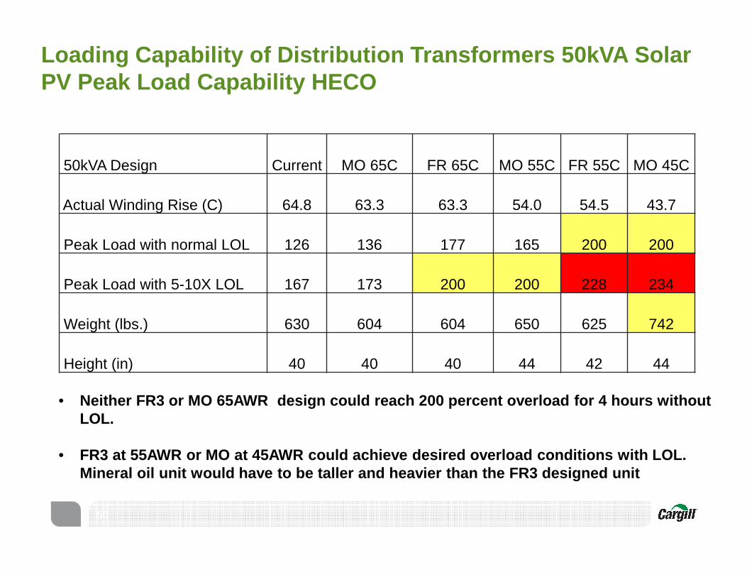
Loading Capability of Distribution Transformers 50k VA Solar PV Peak Load Capability HECO
50
50kVA Design Current MO 65C FR 65C MO 55C FR 55C MO 45C
Actual Winding Rise (C) 64.8 63.3 63.3 54.0 54.5 43.7
Peak Load with normal LOL 126 136 177 165 200 200
Peak Load with 5-10X LOL 167 173 200 200 228 234
Weight (lbs.) 630 604 604 650 625 742
Height (in) 40 40 40 44 42 44
• Neither FR3 or MO 65AWR design could reach 200 per cent overload for 4 hours without LOL.
• FR3 at 55AWR or MO at 45AWR could achieve desired o verload conditions with LOL. Mineral oil unit would have to be taller and heavie r than the FR3 designed unit
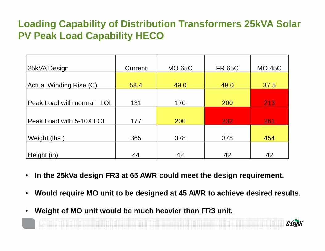
Loading Capability of Distribution Transformers 25k VA Solar PV Peak Load Capability HECO
51
25kVA Design Current MO 65C FR 65C MO 45C
Actual Winding Rise (C) 58.4 49.0 49.0 37.5
Peak Load with normal LOL 131 170 200 213
Peak Load with 5-10X LOL 177 200 232 261
Weight (lbs.) 365 378 378 454
Height (in) 44 42 42 42
• In the 25kVa design FR3 at 65 AWR could meet the de sign requirement.
• Would require MO unit to be designed at 45 AWR to a chieve desired results.
• Weight of MO unit would be much heavier than FR3 un it.

Testing
52

Performance Test Modification FR3 fluid vs. MO result
Notes (Refer G2300 p13)
Dielectric Breakdown Voltage
Stand time 30 minutes, ASTM: 2mm gap, IEC: 2.5 mm gap
Same None
Water Content Use relative saturation to compare different type of dielectric fluids
Higher Maintains dielectric strength at higher absolute water contents
Viscosity None Higher Indicator of oxidation
FR3 fluid performance and diagnostic testing is similar to MO with a few modifications
• Some traditionally acceptable indicator of mineral oil performance may not apply (interfacial tension)
• BDV and DDF are the best parameters to evaluate the general contamination• FR3 fluid is a mixture of relatively polar triglycerides (long-chain fatty ester
molecules)• Have unsaturation and ability to form hydrogen bonds
• Mineral oil is non-polar and hydrophobic• Difference in basic chemistry accounts for disparate values
RULE OF THUMB – “WHAT DO YOU DO WITH MINERAL OIL?”
53

Diagnostic testing results and modifications Diagnostic test Test modification requirements FR3 flu id vs.
MO resultNotes (Refer G2300 p14-17)
Water Content None Higher Helps dry transformer insulation
Dissipation FactorNone – meticulously clean cell if using for FR3 and MO
Higher Higher transformer power factor
Acid Number None HigherFR3 fluid generates long chain fatty acids that are mild and non-corrosive
Interfacial Tension None Lower Not useful for FR3 fluid – use dissipation factor
Resistivity None Lower Lower transformer insulation resistance
Pour Point Heat fluid to 50C, cool to room temp Higher Effects low temperature mechanical movement
Gassing Tendency None NA NA
Oxidation InhibitorUse GC instead of IR methodUse DSC to evaluate inhibitor additives
NA Replenish inhibitor if content falls below 0.12%
Oxidation Stability Use IEC 62770 method NA NA
PCB Content Packed column, sulfuric acid treatment None Not found in vegetable oils
Flash and Fire Points None Higher Upgrades fire safety
Dissolved Gas Analysis None Different Stray gases differ from mineral oil
Corrosive Sulfur None None Not found in vegetable oils
Furanic Compound None - for new FR3 fluid Different Interferences from degradation products
Particle CountDilute FR3 fluid 75% with filteredheptane or hexane
NAAir bubbles in FR3 fluid may not dissipate and are detected as particles
54

1. Refer to IEEE C57.155 for stray gassing levels
• If only one data set, use IEEE C57.104 “Condition” method as first best guess (account for stray gassing)
• If Condition warrants it, take another sample
2. Check gassing rate• Gassing rate low: done• Gassing rate significant: continue to 3
3. Use IEEE “Key Gases” method and Duval triangle method to diagnose
4. Use additional methods as needed
Dissolved gas analysis in a nutshell
55
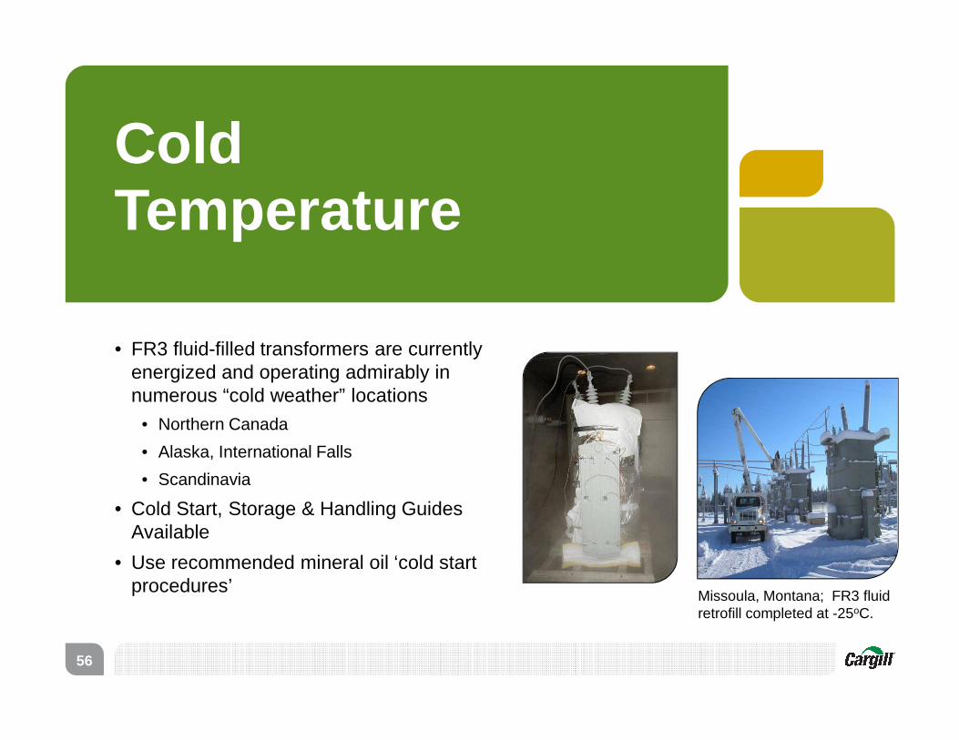
Cold Temperature
• FR3 fluid-filled transformers are currently energized and operating admirably in numerous “cold weather” locations
• Northern Canada
• Alaska, International Falls
• Scandinavia
• Cold Start, Storage & Handling Guides Available
• Use recommended mineral oil ‘cold start procedures’
Missoula, Montana; FR3 fluid retrofill completed at -25oC.
56
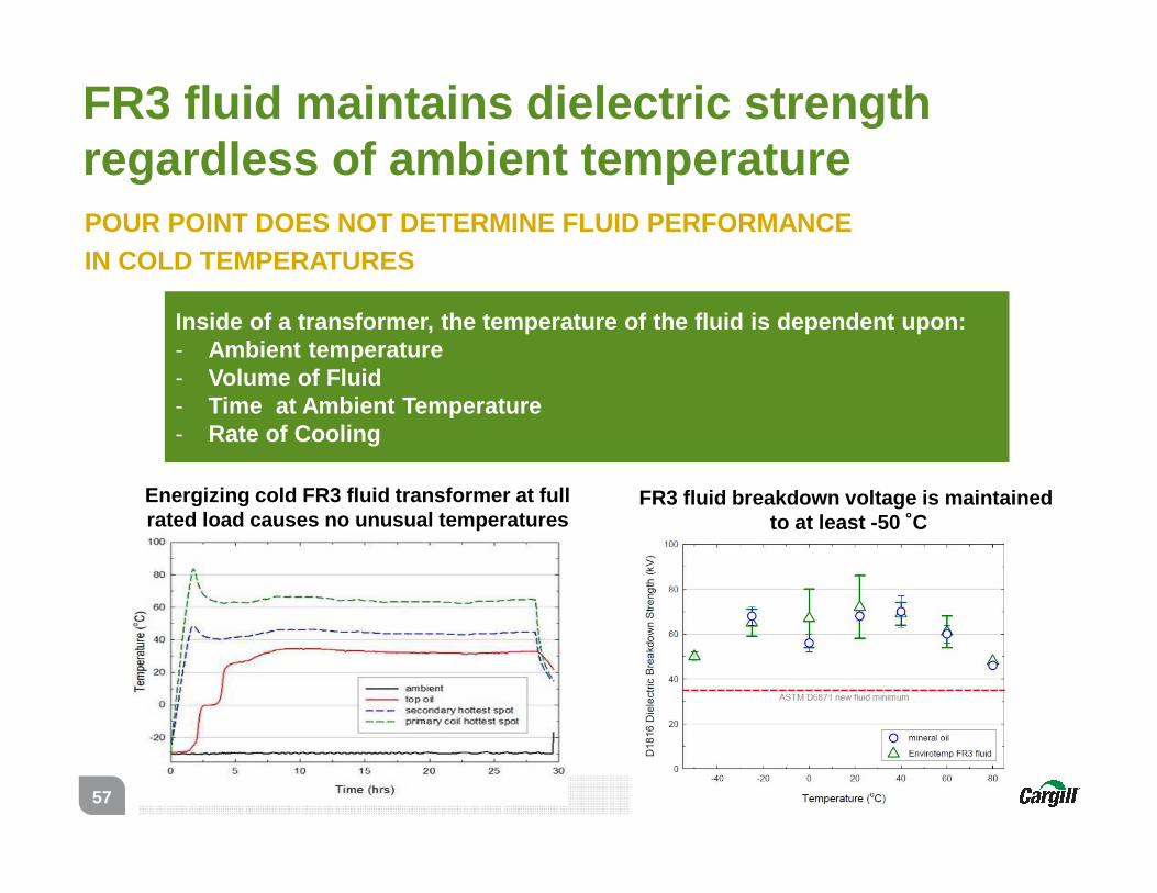
FR3 fluid maintains dielectric strength regardless of ambient temperature
Inside of a transformer, the temperature of the flu id is dependent upon: - Ambient temperature- Volume of Fluid- Time at Ambient Temperature- Rate of Cooling
Energizing cold FR3 fluid transformer at full rated load causes no unusual temperatures
FR3 fluid breakdown voltage is maintainedto at least -50 ˚C
POUR POINT DOES NOT DETERMINE FLUID PERFORMANCE IN COLD TEMPERATURES
57
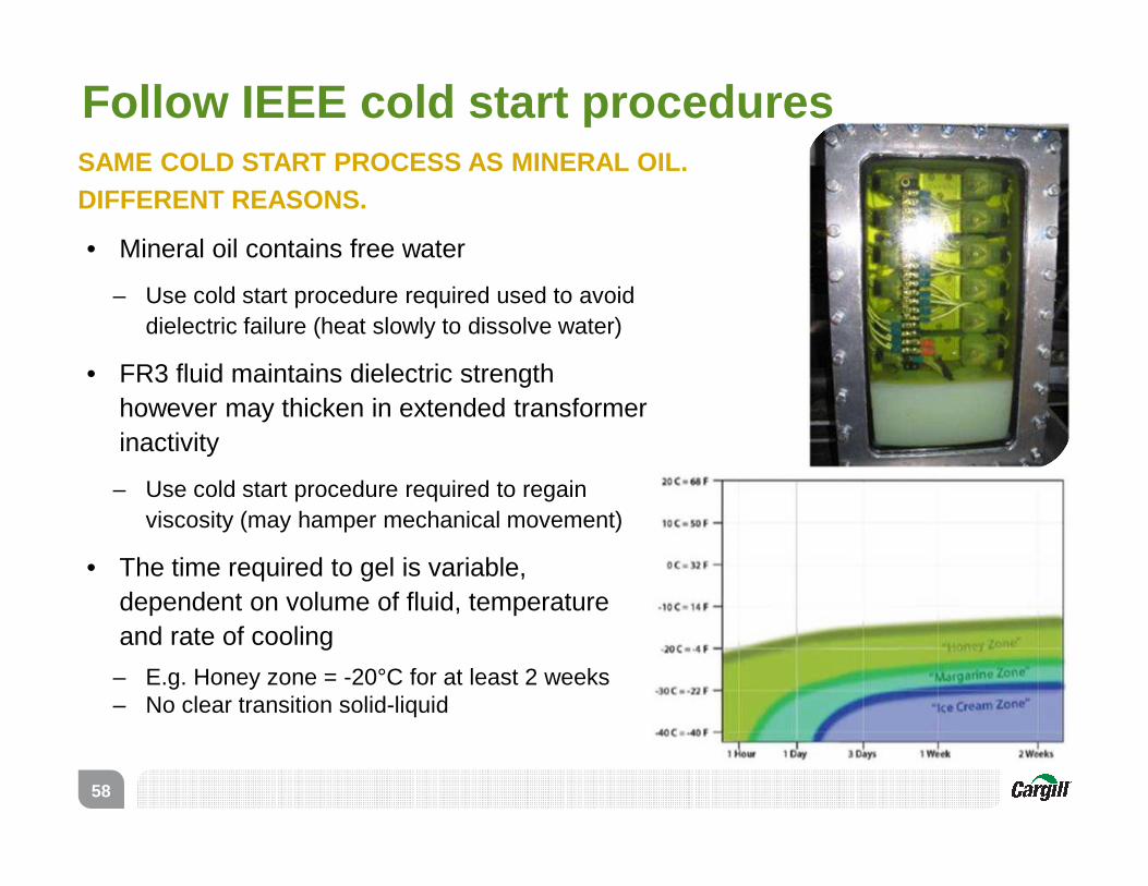
• Mineral oil contains free water
– Use cold start procedure required used to avoid dielectric failure (heat slowly to dissolve water)
• FR3 fluid maintains dielectric strength however may thicken in extended transformer inactivity
– Use cold start procedure required to regain viscosity (may hamper mechanical movement)
• The time required to gel is variable, dependent on volume of fluid, temperature and rate of cooling
– E.g. Honey zone = -20°C for at least 2 weeks – No clear transition solid-liquid
Follow IEEE cold start procedures SAME COLD START PROCESS AS MINERAL OIL. DIFFERENT REASONS.
58

Oxidation Stability
• FR3 is recommended in all non-free breathing transformers
• Both mineral oil and natural esters oxidize – takes years, not days
• The fluids oxidize differently• Products of mineral oil oxidation form sludge
precipitates
• Products of natural ester oxidation form oligomers (larger molecules) that stay in solution
• Thin film polymerization is an avoidable concern that must be accounted for in handling procedures
• The long term effect on the transformer is the same: less efficient heat transfer
59

Drying Process
• Drying of new materials (not yet impregnated)• No restrictions regarding oven types
• Drying of impregnated materials• Clean the surfaces using a compatible solvent
(kerosene, alcohol or warm mineral oil)• Keep all insulation material immersed in
insulation fluid or nitrogen gas• Wrap the windings and insulation materials
completely using plastic film (stretch) for preventing contact with ambient air
• Dry impregnated coils using hot FR3 fluid, kerosene vapors or nitrogen
DO NOT USE HOT AIR (DRYING) OVENS FOR IMPREGNATED ASSEMBLIES
Hot air oven is not recommended for previously impr egnated materials, due to oxidation of thin films of FR3
60

REDUCE EXPOSURE TO AIR TO MINIMINZE POTENTIAL FOR THIN FILM POLYMERIZATION
• For smooth surfaces (e.g. steel), limit the exposure to air and UV to 7 calendar days
• For porous surfaces (e.g. paper), limit the exposure to air and UV to 20 calendar days
• Clean the surfaces using a compatible solvent (kerosene, alcohol or warm mineral oil, temp. >60°C)
• Keep all insulation material immersed in insulation fluid or
• Wrap the windings and insulation materials completely using plastic film (stretch) for preventing contact with ambient air
• Avoid hot air (drying) ovens
Oxidation stability is a consideration for routine maintenance
61

The Transformation
62
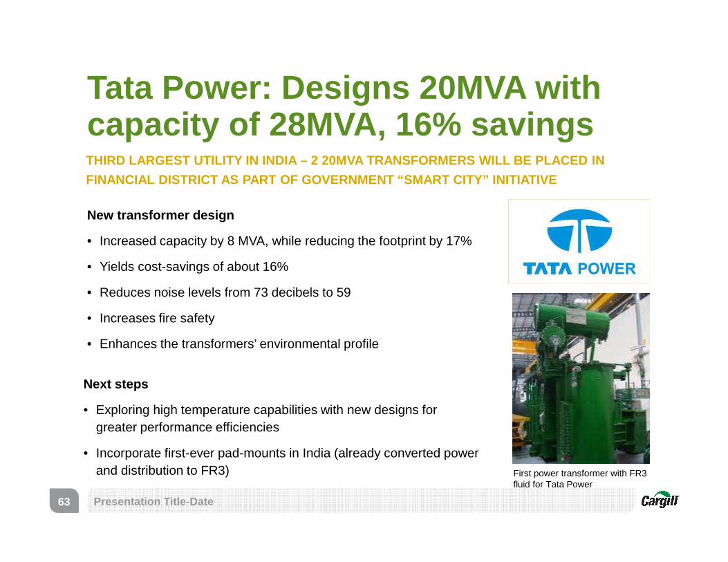
Tata Power: Designs 20MVA with capacity of 28MVA, 16% savingsTHIRD LARGEST UTILITY IN INDIA – 2 20MVA TRANSFORMER S WILL BE PLACED IN
FINANCIAL DISTRICT AS PART OF GOVERNMENT “SMART CIT Y” INITIATIVE
New transformer design
• Increased capacity by 8 MVA, while reducing the footprint by 17%
• Yields cost-savings of about 16%
• Reduces noise levels from 73 decibels to 59
• Increases fire safety
• Enhances the transformers’ environmental profile
Presentation Title-Date63
Next steps
• Exploring high temperature capabilities with new designs for greater performance efficiencies
• Incorporate first-ever pad-mounts in India (already converted power and distribution to FR3) First power transformer with FR3
fluid for Tata Power

Advantages available today and new advancements on the horizon
• 100 kVA
• 65°C AWR
• 110°C HST
• 20.55 years
• Insulation system likely failure mode
• 155°C fire point
• Petroleum based fluid
• Limited overload potential
• 100 kVA
• 75°C AWR
• 120°C HST
• >20.55 years
• Improved reliability -
Robust insulation system
• Improved fire safety -
360°C fire point
• Best in class environmental
properties
65C AWR/110 HST MO
Insulation failure mode
• 64
• 100 kVA
• 85°C AWR
• 130°C HST
• 20.55 years
• Improved reliability -
Robust insulation system
• Improved fire safety –
360°C fire point
• Best in class environmental
properties
• Reduced initial price
In the past Available today Working towards
75C AWR/120 HST FR3
Increased load capability
85C AWR/130 HST FR3
Reduced size/footprint