Embed Size (px)
Citation preview

Page 1 of 12
TECHNICAL APPROVALS FOR CONSTRUCTION
APPROVAL
INSPECTION
TESTING
CERTIFICATION
Natural Building TechnologiesThe HangarWorminghall RoadOakleyBuckinghamshire HP18 9ULTel: 01844 338 338 Fax: 01844 338 525e-mail: [email protected]: www.natural-building.co.uk
British Board of Agrément tel: 01923 665300Bucknalls Lane fax: 01923 665301Garston, Watford e-mail: [email protected] WD25 9BA website: www.bbacerts.co.uk©2010
The BBA is a UKAS accredited certification body — Number 113. The schedule of the current scope of accreditation for product certification is available in pdf format via the UKAS link on the BBA website at www.bbacerts.co.uk
Readers are advised to check the validity and latest issue number of this Agrément Certificate by either referring to the BBA website or contacting the BBA direct.
NBT DIFFUTHERM EXTERNAL WALL INSULATION SYSTEM
NBT DIFFUTHERM EXTERNAL WALL INSULATION SYSTEM FOR USE ON TIMBER FRAMES
PRODUCT SCOPE AND SUMMARY OF CERTIFICATE
This Certificate relates to the NBT Diffutherm External Wall Insulation System for use on Timber Frames, for use as an external wall insulation system employing wood-fibre boards rendered with a mineral render and fixed to vapour open timber-frame constructions on domestic and non-domestic buildings.
AGRÉMENT CERTIFICATION INCLUDES:• factors relating to compliance with Building
Regulations where applicable• factors relating to additional non-regulatory
information where applicable• independently verified technical specification• assessment criteria and technical investigations• design considerations• installation guidance• regular surveillance of production• formal three-yearly review.
KEY FACTORS ASSESSEDThermal performance — the system can be used to improve the performance of an external timber frame wall (see section 5).Strength and stability — the system can adequately resist wind loads and in certain applications, impact damage (see section 6).Behaviour in relation to fire — the system can be designed to meet the UK requirements concerning fire performance (see section 7).Condensation risk — the performance of the system with regard to interstitial and surface condensation has been considered (see section 10).Durability — the design life of the system under typical conditions has been considered as part of this assessment (see section 12).
Agrément Certificate10/4723
Product Sheet 2
The BBA has awarded this Agrément Certificate to the company named above for the system described herein. This system has been assessed by the BBA as being fit for its intended use provided it is installed, used and maintained as set out in this Certificate.
On behalf of the British Board of Agrément
Date of First issue: 9 February 2010 Chris Hunt Greg Cooper
Head of Approvals — Physics Chief Executive
Page 2 of 12
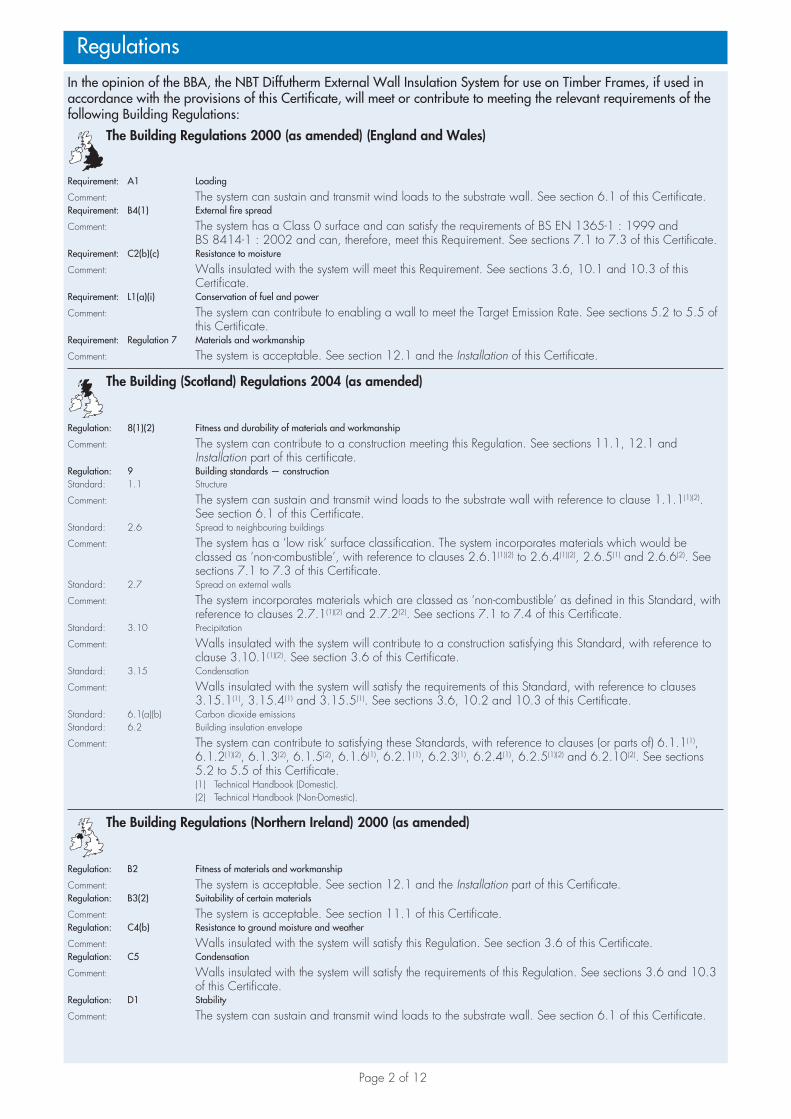
In the opinion of the BBA, the NBT Diffutherm External Wall Insulation System for use on Timber Frames, if used in accordance with the provisions of this Certificate, will meet or contribute to meeting the relevant requirements of the following Building Regulations:
The Building Regulations 2000 (as amended) (England and Wales)
Requirement: A1 Loading
Comment: The system can sustain and transmit wind loads to the substrate wall. See section 6.1 of this Certificate.Requirement: B4(1) External fire spread
Comment: The sys tem has a Class 0 surface and can satisfy the requirements of BS EN 1365-1 : 1999 and BS 8414-1 : 2002 and can, therefore, meet this Requirement. See sections 7.1 to 7.3 of this Certificate.
Requirement: C2(b)(c) Resistance to moisture
Comment: Walls insulated with the system will meet this Requirement. See sections 3.6, 10.1 and 10.3 of this Certificate.
Requirement: L1(a)(i) Conservation of fuel and power
Comment: The system can contribute to enabling a wall to meet the Target Emission Rate. See sections 5.2 to 5.5 of this Certificate.
Requirement: Regulation 7 Materials and workmanship
Comment: The system is acceptable. See section 12.1 and the Installation of this Certificate.
The Building (Scotland) Regulations 2004 (as amended)
Regulation: 8(1)(2) Fitness and durability of materials and workmanship
Comment: The system can contribute to a construction meeting this Regulation. See sections 11.1, 12.1 and Installation part of this certificate.
Regulation: 9 Building standards — constructionStandard: 1.1 Structure
Comment: The system can sustain and transmit wind loads to the substrate wall with reference to clause 1.1.1(1)(2). See section 6.1 of this Certificate.
Standard: 2.6 Spread to neighbouring buildings
Comment: The system has a ‘low risk’ surface classification. The system incorporates materials which would be classed as ‘non-combustible’, with reference to clauses 2.6.1(1)(2) to 2.6.4(1)(2), 2.6.5(1) and 2.6.6(2). See sections 7.1 to 7.3 of this Certificate.
Standard: 2.7 Spread on external walls
Comment: The system incorporates materials which are classed as ‘non-combustible’ as defined in this Standard, with reference to clauses 2.7.1(1)(2) and 2.7.2(2). See sections 7.1 to 7.4 of this Certificate.
Standard: 3.10 Precipitation
Comment: Walls insulated with the system will contribute to a construction satisfying this Standard, with reference to clause 3.10.1(1)(2). See section 3.6 of this Certificate.
Standard: 3.15 Condensation
Comment: Walls insulated with the system will satisfy the requirements of this Standard, with reference to clauses 3.15.1(1), 3.15.4(1) and 3.15.5(1). See sections 3.6, 10.2 and 10.3 of this Certificate.
Standard: 6.1(a)(b) Carbon dioxide emissionsStandard: 6.2 Building insulation envelope
Comment: The system can contribute to satisfying these Standards, with reference to clauses (or parts of) 6.1.1(1), 6.1.2(1)(2), 6.1.3(2), 6.1.5(2), 6.1.6(1), 6.2.1(1), 6.2.3(1), 6.2.4(1), 6.2.5(1)(2) and 6.2.10(2). See sections 5.2 to 5.5 of this Certificate.
(1) Technical Handbook (Domestic). (2) Technical Handbook (Non-Domestic).
The Building Regulations (Northern Ireland) 2000 (as amended)
Regulation: B2 Fitness of materials and workmanship
Comment: The system is acceptable. See section 12.1 and the Installation part of this Certificate.Regulation: B3(2) Suitability of certain materials
Comment: The system is acceptable. See section 11.1 of this Certificate.Regulation: C4(b) Resistance to ground moisture and weather
Comment: Walls insulated with the system will satisfy this Regulation. See section 3.6 of this Certificate.Regulation: C5 Condensation
Comment: Walls insulated with the system will satisfy the requirements of this Regulation. See sections 3.6 and 10.3 of this Certificate.
Regulation: D1 Stability
Comment: The system can sustain and transmit wind loads to the substrate wall. See section 6.1 of this Certificate.
Regulations

Page 3 of 12
Regulation: E5(a) External fire spread
Comment: The system has a Class 0 surface and can satisfy the requirements of BS EN 1365-1 : 1999 and BS 8414-1 : 2002 and can, therefore, meet this Regulation. See sections 7.1 to 7.3 of this Certificate.
Regulation: F2(a)(i) Conservation measuresRegulation: F3 Target carbon dioxide Emissions Rate
Comment: The system will enable a wall to meet the requirements of these Regulations. See sections 5.2 to 5.5 of this Certificate.
Construction (Design and Management) Regulations 2007Construction (Design and Management) Regulations (Northern Ireland) 2007
Information in this Certificate may assist the client, CDM co-ordinator, designer and contractors to address their obligations under these Regulations.See section: 2 Delivery and site storage (2.3).
Non-regulatory Information
NHBC Standards 2008In the opinion of the BBA, the use of the NBT Diffutherm External Wall Insulation System for use on Timber Frames, in relation to this Certificate, is not subject to the requirements of these Standards.
General
This Certificate relates to the NBT Diffutherm External Wall Insulation System for use on Timber Frames which comprises insulation board with basecoat and decorative finishes.
The system is applied to the outside of external timber frame walls and is suitable for use on new or existing buildings. The system is for use in sheltered to moderate exposure zones. Additional precautionary measures are required for use of the system in severe exposure zones (see section 3.3). The use of the system within very severe exposure zones is not covered within the scope of this Certificate. For use within very severe exposure zones advice from the Certificate holder must be sought.
Technical Specification
1 Description1.1 The NBT Diffutherm External Wall Insulation System for use on Timer Frames comprises a wood-fibre insulation board, mechanically fixed to a timber frame. A basecoat render is applied directly to the insulation boards incorporating a reinforcing mesh and a mineral topcoat with a decorative finish.
1.2 Components of the system include:• Pavatex NBT Diffutherm wood-fibre insulation (60 mm — 120 mm thickness)• Baumit BM33 basecoat• Wemico glassfibre mesh R131• Baumit DG27 adhesion coat (primer) — optional• Baumit SEP01, SEP02, SEP03 or SEP04 decorative coat• Baumit SilikonFarbe equalising paint• Fischer 6H 100 or EJOT TKR fixing screws and SBH-T washer plate fixings• Base rail and clip on profile• APU rail and compriband sealing band.
2 Delivery and site storage2.1 The Insulation is delivered to site shrink-wrapped in polythene packs which carry the manufacturer’s and product identification marks and batch numbers.
2.2 The insulation boards should be stored on a firm, clean, level base, off the ground and must be protected from prolonged exposure to sunlight either by storing opened packs under cover in dry conditions or re-covering with opaque polythene sheeting.
2.3 Care must be taken when handling the insulation boards to avoid both damage and contact with solvents or bitumen products. The boards must not be exposed to open flame or other ignition sources.
2.4 Bagged materials should be stored in dry conditions, off the ground, and be protected from frost at all times.
2.5 The primer and equalising paint should be stored in a safe area, under cover, and be protected from excessive heat and frost at all times.

Page 4 of 12
Assessment and Technical Investigations
The following is a summary of the assessment and technical investigations carried out on the NBT Diffutherm External Wall Insulation System for use on Timber Frames.
Design Considerations
3 General3.1 The NBT Diffutherm External Wall Insulation System for use on Timber Frames, when installed in accordance with this Certificate, is effective in reducing the thermal transmittance (U value) of the walls of new and existing buildings. It is essential that the detailing techniques specified in this Certificate are carried out to a high standard, if the ingress of water into the insulation is to be avoided and the full thermal benefit obtained from treatment with the system.
3.2 The system will improve the weather resistance of a wall and provide a decorative finish. However, it may be installed only where other routes for moisture penetration have been dealt with separately and where there are no signs of dampness on the inner surface of the wall, other than those caused solely by condensation. The system can be used to overcome condensation associated with the internal wall surface.
3.3 In areas of severe exposure, additional precautionary measures including site supervision, incorporating a detailed quality control checklist should be considered in accordance with the Certificate holders recommendations.
3.4 The use of the system within very severe exposure zones is not covered within the scope of this Certificate.
3.5 Existing buildings subject to national Building Regulations should have wall surfaces in accordance with section 13 of this Certificate.
3.6 When using the system, consideration must be given to the overall design to minimise the risk of condensation and the recommendations of BS 5250 : 2002 should be followed.
4 Practicality of installationThe system should only be installed by installers who have been trained and approved by the Certificate holder (see section 14 of this Certificate).
5 Thermal performance5.1 Calculations of the thermal transmittance (U value) of a specific wall construction should be carried out in accordance with BS EN ISO 6946 : 2007 and BRE report (BR 443 : 2006) Conventions for U-value calculations, using the declared thermal conductivity (� 90/90 value) of 0.043 W·m–1K–1 for the insulation. The U value of a typical wall construction will depend on the insulating value of the wall and its finish. Example U values are given in Table 1.
Table 1 Example U values for various insulation thicknesses
Insulation thickness(mm)
U value for example construction(1)
(W·m–2·K–1)
60 0.27
80 0.25
100 0.22
120 0.20
(1) 3 mm plaster skim on 12.5 mm plasterboard, 25 by 40 mm timber batten, 9 mm oriented strand board (OSB), 89 mm timber stud infilled with insulation, mechanically fixed NBT Diffutherm wood-fibre board coated with 8 mm meshed external render.
5.2 When considering insulation requirements, designers should refer to the detailed guidance contained in the documents supporting the national Building Regulations. The U values shown in Table 1 indicate that the product can enable a wall to achieve typical design U values referred to in those supporting documents. See
Tables 2 and 3.

Page 5 of 12
Table 2 Typical design U values for walls — England and Wales, and Northern Ireland
Construction type U values (W·m–2·K–1)
Mean for new extensions(1) 0.30
‘Notional’ mean in SAP and SBEM and limit mean for new-build 0.35
Mean for replacement, renovated, and retained walls and non-domestic consequential improvements(1) 0.35
Individual limit for new-build and flexible approaches(1) 0.70
(1) Alternative or flexible approaches are given in relevant documents supporting the national Building Regulations.
Table 3 Typical design U values for walls — Scotland
Construction type U values (W·m–2·K–1)
‘Notional’ mean for dwellings in SAP and the ‘simplified’ approach:– solid fuel, package 6– other fuels, packages 1–5
0.200.25
Mean for new extensions, conversions and alterations(1) 0.27
Mean for stand-alone buildings less than 50 m2 0.27
‘Notional’ mean for non-domestic in SBEM and limit mean for new-build and stand-alone buildings of 50 m2 or more 0.30
Individual limit for; new-build, extensions, conversions, alterations and stand-alone buildings less than 50 m2 0.70
(1) Alternative or flexible approaches are given in relevant documents supporting the national Building Regulations.
New buildings5.3 Walls with U values lower than (or the same as, for dwellings in Scotland) the relevant ‘notional’ value specified in section 5.2 will contribute to a building meeting its Target Emission Rate. Walls with higher U values will require additional energy saving measures in the building envelope and/or services.
5.4 The system can maintain, or contribute to maintaining, continuity of thermal insulation at junctions between external walls and other building elements. Example junction detail shown in Figure 1 will allow use of the default psi values for Accredited Construction details in Target Emission Rate calculations to SAP 2005 or the Simplified Building Energy Model (SBEM). Detailed guidance in this respect and on limiting heat loss by air infiltration can be found in:England and Wales — Limiting thermal bridging and air leakage: Robust construction details for dwellings and similar buildings, TSO 2002 or Accredited Construction Details (version 1.0)Scotland — Accredited Construction Details (Scotland) Northern Ireland — Accredited Construction Details (version 1.0).
Figure 1 Junction/lintel detail (1)
= 0.009 W m K= 0.17
• •–1 –1
Uw W m K= 1.53 W m K
• •
• •
–2 –1
–2 –1UFr
�
(1) The Certificate holder can provide psi and y value calculations which give y values lower (down to 0.02 W·m–2·K–1 — see Figure 1) than the default values (0.08 W·m–2·K–1) as found in the Accredited Construction details in Target Emission Rate calculations to SAP 2005 or the Simplified Building Energy Model (SBEM). Note, the ability of the Certificate holder to calculate psi values has not been assessed by the BBA.

Page 6 of 12
Existing buildings5.5 For existing buildings, extensions and conversions, walls will be acceptable where they do not exceed the relevant U value in Table 2 or 3 and junctions and openings comply with section 5.4 or BRE report (BR 262 : 2002) Thermal insulation: avoiding risks.
6 Strength and stability6.1 When installed on suitable walls, the system can adequately transfer self weight and negative and positive wind loads to the substrate wall.
6.2 The system has adequate resistance to impact and abrasion where walls are exposed and have some protection, eg walls of private dwellings and walls of communal dwellings above ground-floor level. Where the system may be exposed to severe mechanical or malicious impact, eg walls of public buildings at ground-floor level, precautions such as supplementary reinforcement, may be required to reduce the risk of damage. Guidance may be obtained from the Certificate holder or BS 8200 : 1985.
6.3 Assessment of structural performance should be carried out by a suitably qualified engineer or other appropriately qualified person to confirm that the substrate wall has adequate strength to resist the additional loads that may be applied as a result of installing the system ignoring any positive contribution that may occur from the system.
6.4 The fixing-to-panel-edge distance should be between 50 mm and 100 mm.
6.5 The ultimate wind load to be resisted by the system should be determined by calculating the wind load in accordance with BS 6399-2 : 1997, BS EN 1991-1-4 : 2005 and multiplying by a load factor of 1.5 (as recommended in EN 1990 : 2002). Special consideration should be given to locations with high wind load pressure coefficients (additional fixings may be required).
7 Behaviour in relation to fire7.1 The external surfaces of the system are classified as non combustible or ‘low risk’ as defined in the documents supporting the national Building Regulations. The system, therefore, may be used in accordance with the provisions of:
England and Wales — Approved Document B, Volume 1, paragraph 8.4 and Volume 2, paragraphs 12.5 and 12.6 (see also Diagram 40)
Scotland — Mandatory Standards 2.6 and 2.7, clauses 2.6.1(1)(2) to 2.6.4(1)(2), 2.6.5(1), 2.6.6(2), 2.7.1(1)(2) and 2.7.2(2) respectively and Annexes 2.C(1) and 2.E(2)
(1) Technical Handbook (Domestic).(2) Technical Handbook (Non-Domestic).
Northern Ireland — Technical Booklet E, paragraph 4.3 (see also Diagram 4.1).
7.2 The documents listed in section 7.1 give full details of permissible heights and boundary conditions of domestic and non-domestic buildings and the relevant guidance with regard to external wall claddings of external wall insulation systems with render surfaces. However, the following information is for guidance purposes:
England and Wales and Northern IrelandThe system is acceptable:(a) one metre or more from a boundary(b) less than one metre from a boundary, provided the wall meets the relevant requirements for fire resistance from both sides and extent of unprotected areas.(c) on walls (a) or (b) up to storey heights of 18 m.
ScotlandThe system is acceptable:(a) more than one metre from a boundary, but must be included, with some minor exceptions, in the calculation of unprotected area(b) on wall (a) up to storey heights of 18 m.
7.3 The classifications stated in section 7.1 were achieved on light-coloured render. However, the classification of darker colours should be confirmed by:England and Wales — test or assessment in accordance with Approved Document B, Appendix A, Clause 1Scotland — test to conform with Regulation 9, Table to Annex 2.C(1) and 2.E(2)
(1) Technical Handbook (Domestic).(2) Technical Handbook (Non-Domestic).
Northern Ireland — test or assessment by a UKAS accredited laboratory or an independent consultant with appropriate experience.
Page 7 of 12
7.4 In buildings not subject to the Building Regulations, it is recommended that designers should consider the use of the guidance given in section 7.2.
7.5 The system has been tested on timber frames in accordance with BS EN 1365-1 : 1999 and satisfied the requirement of 60 minute load bearing capacity, integrity and insulation where relevant. The timber frame construction included 3 mm plaster skim on 12.5 mm plasterboard, 25 by 40 mm timber batten, 9 mm OSB, timber stud infilled with mineral insulation, mechanically fixed NBT Diffutherm wood-fibre board coated with 8 mm meshed external render.
8 Proximity of flues and appliancesWhen the system is installed in close proximity to certain flue pipes the relevant provisions of the national Building Regulations should be met:England and Wales — Approved Document JScotland — Mandatory Standard 3.19, clause 3.19.4(1)(2)
(1) Technical Handbook (Domestic).(2) Technical Handbook (Non-Domestic).
Northern Ireland — Technical Booklet L.
9 Rain penetration9.1 Test and site examinations show that the system will resist the passage of moisture.
9.2 Designers and installers should take particular care in detailing around openings, penetrations and movement joints to minimise the risk of rain ingress.
10 Condensation riskSurface condensation
10.1 Walls will limit the risk of surface condensation adequately when the thermal transmittance (U value) does not exceed 0.7 W·m–2·K–1 at any point and the junctions with other elements are designed in accordance with the relevant requirements of the publications referred to in section 5.
10.2 Walls and ceilings will adequately limit the risk of surface condensation when the thermal transmittance (U value) does not exceed 1.2 W·m–2·K–1 at any point. Guidance may be obtained from BS 5250 : 2002, Section 8 and BRE report (BR 262 : 2002) Thermal insulation: avoiding risks.
Interstitial condensation10.3 Walls incorporating the system will adequately limit the risk of interstitial condensation when they are designed and constructed in accordance with BS 5250 : 2002 (Section 8 and Annex D).
11 Maintenance11.1 Regular checks should be made on the installed system, particularly at joints and on external plumbing fitments, to ensure that ingress of water does not occur. Necessary repairs should be effected immediately.
11.2 Damaged areas must be repaired using the appropriate components and the procedures detailed in the Certificate holder’s installation instructions.
12 Durability12.1 The results of accelerated ageing tests in accordance with MOAT No 22 : 1988 indicate that the system is durable. The system should remain effective for at least 30 years, provided any damage to the surface finish is repaired immediately, and regular maintenance is undertaken including checks on joints in the system and external
plumbing fitments to prevent leakage of rainwater into the system, enabling steps to be taken to correct the defects.
12.2 The textured finishes may also become soiled in time, the rate depending on locality. The appearance may be restored by a suitable powerwash or, if required, by the application of a compatible paint; however, great care should be taken not to adversely affect the water vapour transmission or fire characteristics of the system. The advice of the Certificate holder should be sought.
Page 8 of 12
Installation
13 Site survey and preliminary work13.1 A pre-installation survey of the property is carried out to determine suitability for treatment and any repairs necessary to the building structure before application of the NBT Diffutherm External Wall Insulation System for use on Timber Frames. A specification is prepared for each elevation of the building indicating:• where required, additional corner mesh and reinforcement• the position of beads• detailing around windows, doors and at eaves• damp-proof course (dpc) level• exact position of expansion joints• areas where flexible sealants must be used• any alterations to external plumbing• where required, the position of fire barriers.
13.2 Mechanical fixings are used to secure the system. An assessment and recommendation is made on the type and number of fixings required to withstand the building’s expected wind loading based on calculations using the test data, the relevant wind speed data for the site and, in the absence of a formal requirement, a safety factor of 3 should be used.
13.3 All modifications, such as necessary repairs to the building are completed before installation commences.
13.4 Detailing around window reveals should be carefully carried out to ensure a weathertight seal.
13.5 It is recommended that external plumbing be removed before installation and alterations made to underground drainage, where appropriate, to accommodate repositioning of the plumbing on the finished face of the system.
14 Approved installers14.1 The Certificate holder operates an Approved Installer Scheme for the system, under which installers are trained, approved and regularly reviewed by the Certificate holder, to demonstrate that they are competent to carry out installation of the system in accordance with this Certificate. Details of approved installers are available from the Certificate holder.
14.2 The Certificate holder may manage individual projects to ensure proper detailing in areas where there may be increased risk of water ingress due to location.
15 ProcedureGeneral15.1 Application is carried out in accordance with the current installation instructions of the Certificate holder.
15.2 Weather conditions should be monitored to ensure correct application and curing conditions. Application of the undercoat and finishes should not be carried out at temperatures below 5°C or above 30°C, nor if exposure to frost is likely. The coating must be protected from rapid drying.
15.3 All rendering should be in accordance with the relevant recommendations of BS EN 13914-1 : 2005.
Positioning and securing insulation boards15.4 The base profile is secured to the external wall above the dpc using approved profile fixings at 400 mm maximum centres.
15.5 The first run of insulation boards is positioned on the base profile. The boards are pressed firmly against the wall.
15.6 Mechanical fixings should be installed through the board face into the studwork beyond with a minimum fixing rate of 3 fixings per stud per board.
15.7 Care must be taken to ensure that all board edges are butted tightly together, and surface alignment should be checked as work proceeds.
15.8 To fit around details such as doors and windows, insulation boards may be cut with a sharp knife or a fine toothed saw. If required, purpose-made window-sills are fitted at this stage. They are designed to prevent water ingress and incorporate drips to shed water clear of the system. Compriband should be applied according to the Certificate holder’s technical manual at all openings and penetrations.
15.9 APU rails should be applied according to the Certificate holder’s technical manual at the sides and heads of all windows and doors.
15.10 Installation continues until the whole wall is completely covered including, where appropriate, the building soffits. Refer to Certificate holder’s technical manual for full application details.

Page 9 of 12
Movement joints15.11 Movement joints have not been assessed as part of this system and advice should be sought from the Certificate holder as to how existing movement joints within the substrate may be accommodated as part of the system.
Reinforced base coat15.12 Additional pieces of reinforcing mesh are used diagonally at the corners of openings, as shown in Figure 2.
Figure 2 Reinforcing mesh requirements at opening details
corner mesh bead
substrate
corner mesh bead
reinforcing mesh strip R131
NBT Diffutherm board
plinth board
15.13 Care should be taken at window reveals if insulation has been omitted from the reveal due to space limitations, as movement may cause cracks at changes of material. Additional reinforcing mesh should be used at window reveals.
15.14 The Baumit BM33 basecoat is prepared and trowel or machine applied to the insulation to a thickness of approximately four mm thick. R131 Reinforcing mesh should be applied to the whole surface and a further two mm coating of Baumit BM33 applied and trowelled flat. The R131 mesh should be positioned in the top third of the basecoat.
15.15 Care should be taken with the basecoat under details such as window sills. The surface of the basecoat should be allowed to cure for one day per mm thickness before surface irregularities are smoothed out using a rasping tool (Grid float). The basecoat render should then be allowed to fully cure for a further four to five days.
Beads15.16 Expansion beads should be fixed in accordance with the Certificate holder’s advice.
15.17 Stop beads are positioned vertically, eg at separating wall positions where the adjoining house does not require treatment.
15.18 Where required, angle beads are fixed to all building corners and to door and window heads and jambs.
Render finishing15.19 The basecoat must be left to cure for at least one day per mm thickness depending on weather conditions before application of the finish.
15.20 The surface of the render basecoat can be primed with DG27 adhesion coat (primer), applied by brush or roller and allowed to dry for a minimum of 24 hours.
15.21 The finish coating should be trowel or machine applied to give the appropriate texture effect.
15.22 To prevent the finish from drying too rapidly, it should not be applied in direct sunlight. The finished render surface should be protected from rain and frost until the material is dry and hard, approximately one day per mm thickness of finish. Continuous surfaces must be completed without a break.
Page 10 of 12
15.23 One to two coats of Baumit SilikonFarbe equalising paint should be applied to the Décor finish surface by brush, roller or spray application, colour matched to the finish, and allowed to dry for 24 hours.
15.24 At the tops of walls the system must be protected by an adequate overhang or by an adequately sealed, purpose-made flashing.
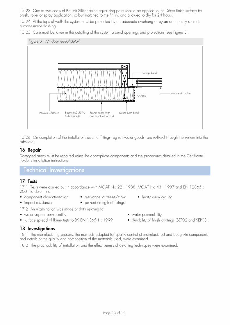
15.25 Care must be taken in the detailing of the system around openings and projections (see Figure 3).
Figure 3 Window reveal detail
Pavatex Diffutherm Baumit MC 55 W(fully meshed)
Baumit decor finishand equalisation paint
corner mesh bead
APU Railwindow sill profile
Compriband
15.26 On completion of the installation, external fittings, eg rainwater goods, are re-fixed through the system into the substrate.
16 RepairDamaged areas must be repaired using the appropriate components and the procedures detailed in the Certificate holder’s installation instructions.
Technical Investigations
17 Tests17.1 Tests were carried out in accordance with MOAT No 22 : 1988, MOAT No 43 : 1987 and EN 12865 : 2001 to determine:• component characterisation • resistance to freeze/thaw • heat/spray cycling• impact resistance • pull-out strength of fixings.
17.2 An examination was made of data relating to:• water vapour permeability • water permeability• surface spread of flame tests to BS EN 1365-1 : 1999 • durability of finish coatings (SEP02 and SEP03).
18 Investigations18.1 The manufacturing process, the methods adopted for quality control of manufactured and bought-in components, and details of the quality and composition of the materials used, were examined.
18.2 The practicability of installation and the effectiveness of detailing techniques were examined.

Page 11 of 12
Bibliography
BS 5250 : 2002 Code of practice for control of condensation in buildings
BS 5628-3 : 2005 Code of practice for the use of masonry — Materials and components, design and workmanship
BS 6399-2 : 1997 Loading for buildings — Code of practice for wind loads
BS 8000-3 : 2001 Workmanship on building sites — Code of practice for masonry
BS 8200 : 1985 Code of practice for design of non-loadbearing external vertical enclosures of buildings
BS 8414-1 : 2002 Fire performance of external cladding systems — Test methods for non-loadbearing external cladding systems applied to the face of a building
BS EN 1365-1 : 1999 Fire resistance tests for loadbearing elements — Walls
BS EN 1991-1-4 : 2005 Eurocode 1 : Actions on structures — General actions — Wind actions
BS EN 13914-1 : 2005 Design, preparation and application of external rendering and internal plastering — External rendering
BS EN ISO 6946 : 2007 Building components and building elements — Thermal resistance and thermal transmittance — Calculation method
EN 12865 : 2001 Hygrothermal performance of building components and building elements — Determination of the resistance of external wall systems to driving rain under pulsating air pressure
MOAT No 22 : 1988 UEAtc Directives for the Assessment of External Insulation Systems for Walls (Expanded Polystyrene Insulation Faced with a Thin Rendering)
MOAT No 43 : 1987 UEAtc Directives for Impact Testing Opaque Vertical Building Components

Page 12 of 12
Conditions of Certification
19 Conditions19.1 This Certificate:• relates only to the product/system that is named and described on the front page• is granted only to the company, firm or person named on the front page — no other company, firm or person may
hold or claim any entitlement to this Certificate• is valid only within the UK• has to be read, considered and used as a whole document — it may be misleading and will be incomplete to be
selective• is copyright of the BBA• is subject to English law.
19.2 Publications and documents referred to in this Certificate are those that the BBA deems to be relevant at the date of issue or re-issue of this Certificate and include any: Act of Parliament; Statutory Instrument; Directive; Regulation; British, European or International Standard; Code of Practice; manufacturers’ instructions; or any other publication or document similar or related to the aforementioned.
19.3 This Certificate will remain valid for an unlimited period provided that the product/system and the manufacture and/or fabrication including all related and relevant processes thereof:• are maintained at or above the levels which have been assessed and found to be satisfactory by the BBA• continue to be checked as and when deemed appropriate by the BBA under arrangements that it will determine• are reviewed by the BBA as and when it considers appropriate.
19.4 In granting this Certificate, the BBA is not responsible for:• the presence or absence of any patent, intellectual property or similar rights subsisting in the product/system or any
other product/system• the right of the Certificate holder to manufacture, supply, install, maintain or market the product/system• individual installations of the product/system, including the nature, design, methods and workmanship of or related
to the installation• the actual works in which the product/system is installed, used and maintained, including the nature, design,
methods and workmanship of such works.
19.5 Any information relating to the manufacture, supply, installation, use and maintenance of this product/system which is contained or referred to in this Certificate is the minimum required to be met when the product/system is manufactured, supplied, installed, used and maintained. It does not purport in any way to restate the requirements of the Health & Safety at Work etc Act 1974, or of any other statutory, common law or other duty which may exist at the date of this Certificate; nor is conformity with such information to be taken as satisfying the requirements of the 1974 Act or of any statutory, common law or other duty of care. In granting this Certificate, the BBA does not accept responsibility to any person or body for any loss or damage, including personal injury, arising as a direct or indirect result of the manufacture, supply, installation, use and maintenance of this product/system.
British Board of Agrément tel: 01923 665300Bucknalls Lane fax: 01923 665301Garston, Watford e-mail: [email protected] WD25 9BA website: www.bbacerts.co.uk©2010