Embed Size (px)
Citation preview
NATIONAL RADIO SYSTEMS COMMITTEE
NRSC-1-B
NRSC AM Preemphasis/ Deemphasis and Broadcast Audio
Transmission Bandwidth Specifications
September, 2012
NAB: 1771 N Street, N.W. CEA: 1919 South Eads Street Washington, DC 20036 Arlington, VA 22202
Tel: (202) 429-5356 Fax: (202) 775-4981 Tel: (703) 907-7660 Fax: (703) 907-8113
Co-sponsored by the Consumer Electronics Association and the National Association of Broadcasters
http://www.nrscstandards.org
NRSC STANDARD
NRSC-1-B
Page 2
NOTICE NRSC Standards, Guidelines, Reports and other technical publications are designed to serve the public interest through eliminating misunderstandings between manufacturers and purchasers, facilitating interchangeability and improvement of products, and assisting the purchaser in selecting and obtaining with minimum delay the proper product for his particular need. Existence of such Standards, Guidelines, Reports and other technical publications shall not in any respect preclude any member or nonmember of the Consumer Electronics Association (CEA) or the National Association of Broadcasters (NAB) from manufacturing or selling products not conforming to such Standards, Guidelines, Reports and other technical publications, nor shall the existence of such Standards, Guidelines, Reports and other technical publications preclude their voluntary use by those other than CEA or NAB members, whether to be used either domestically or internationally. Standards, Guidelines, Reports and other technical publications are adopted by the NRSC in accordance with the NRSC patent policy. By such action, CEA and NAB do not assume any liability to any patent owner, nor do they assume any obligation whatever to parties adopting the Standard, Guideline, Report or other technical publication. This NRSC Standard is considered to have International Standardization implication, but the International Electrotechnical Commission activity has not progressed to the point where a valid comparison between the NRSC Standard and the IEC document can be made. This Standard does not purport to address all safety problems associated with its use or all applicable regulatory requirements. It is the responsibility of the user of this Standard to establish appropriate safety and health practices and to determine the applicability of regulatory limitations before its use.
Published by CONSUMER ELECTRONICS ASSOCIATION
Technology & Standards Department 1919 S. Eads St.
Arlington, VA 22202
NATIONAL ASSOCIATION OF BROADCASTERS Science and Technology Department
1771 N Street, NW Washington, DC 20036
©2012 CEA & NAB. All rights reserved.
This document is available free of charge via the NRSC website at www.nrscstandards.org. Republication
or further distribution of this document, in whole or in part, requires prior permission of CEA or NAB.
NRSC-1-B
Page 3
FOREWORD
This Standard was developed by the National Radio Systems Committee (NRSC) and first published in July 1988 as EIA-549 and ANSI/EIA-549-1988. It was incorporated into the FCC rules in 1989 as a part of the First Report and Order to FCC, Mass Media Docket No. 88-376, in which the Commission defined a "presumptive compliance option" that temporarily allowed analog AM stations incorporating equipment compliant with the NRSC-1 Standard to be considered compliant with revised RF emission requirements. Co-convenors of the NRSC at the time of first adoption of this Standard were Charles T. Morgan, Susquehanna Radio Corp., Bart Locanthi, Pioneer North America, Inc., and Alan Boyer, Sony Corporation of America. NRSC Subgroup convenors were John Marino, NewCity Communications and William F. Gilbert, Delco Electronics Corp. While the period of presumptive compliance has long since passed, incorporation of NRSC-1 transmission hardware remains the primary means for AM stations to comply with emission requirements, as defined in the NRSC-2 Standard and FCC Rules, 47 CFR §73.44 (analog AM) or the NRSC-5 Standard and FCC Rules, 47 CFR §73.404(a) (hybrid AM IBOC). The first revision (NRSC-1-A) was developed by the AM Broadcasting (AMB) Subcommittee of the NRSC, co-chaired by Stanley Salek, Hammett & Edison, Inc., and Jeff Littlejohn, Clear Channel Broadcasting, Inc. This second revision (NRSC-1-B) was developed by the AM & FM Analog Broadcasting (AFAB) Subcommittee of the NRSC, co-chaired by Stanley Salek, Hammett & Edison, Inc., and Gary Kline, Cumulus Media. The NRSC chairman at the time of adoption of NRSC-1-A and NRSC-1-B was Milford Smith, Greater Media, Inc. The NRSC is jointly sponsored by the Consumer Electronics Association and the National Association of Broadcasters. It serves as an industry-wide standards-setting body for technical aspects of terrestrial over-the-air radio broadcasting systems in the United States.
NRSC-1-B
Page 4
CONTENTS
1 SCOPE .................................................................................................................................................. 5
2 REFERENCES ...................................................................................................................................... 5 2.1 Normative References .................................................................................................................. 5 2.2 Normative Reference Acquisition ............................................................................................... 5 2.3 Informative References ................................................................................................................ 5 2.4 Informative Reference Acquisition ............................................................................................. 6
3 INTRODUCTION ................................................................................................................................... 6
4 BASIC DEFINITIONS ............................................................................................................................ 7
5 AM TRANSMISSION PREEMPHASIS ................................................................................................. 7 5.1 In General ...................................................................................................................................... 7 5.2 Description of the Modified 75 µs Preemphasis Curve ............................................................ 7 5.3 Methods for Determining Performance ...................................................................................... 9
5.3.1 Use of Audio Tones ............................................................................................................... 9 5.3.2 Location of Measurement ..................................................................................................... 9
6 AM RECEIVER DEEMPHASIS ............................................................................................................. 9 6.1 In General ...................................................................................................................................... 9 6.2 Description of the Standard Deemphasis Curve ....................................................................... 9 6.3 Methods for Determining Performance .................................................................................... 10 6.4 Notch Filters ................................................................................................................................ 11
7 AUDIO BANDWIDTH FOR AM TRANSMISSION .............................................................................. 12 7.1 In General .................................................................................................................................... 12 7.2 10 kHz Bandwidth for Analog AM Transmission ..................................................................... 12 7.3 Bandwidths for Analog Portion of Hybrid AM IBOC Transmission ...................................... 12 7.4 Method for Determining Performance ...................................................................................... 13
7.4.1 Analog AM Transmission ................................................................................................... 13 7.4.1.1 Location of Measurement ............................................................................................ 13 7.4.1.2 Use of Standard Test Signal ....................................................................................... 13 7.4.1.3 Use of Standard Measurement Devices ..................................................................... 14
7.4.2 Hybrid AM IBOC Transmission .......................................................................................... 14
TABLES
Table 1. Modified 75 µs AM Standard Preemphasis Curve (tabular form) ............................................ 8 Table 2. Modified 75µs AM Standard Deemphasis Curve (tabular form) ............................................ 10
FIGURES
Figure 1. Modified 75 µs AM Standard Preemphasis Curve ................................................................... 8 Figure 2. Modified 75µs AM Standard Deemphasis Curve ................................................................... 10 Figure 3. Frequency response ................................................................................................................. 11 Figure 4. NRSC Stopband Specification for Analog AM Transmission .............................................. 12 Figure 5. Spectra of USASI Noise ............................................................................................................ 14 Figure 6. Pulsed-USASI Noise Generator ............................................................................................... 14
NRSC-1-B
Page 5
NRSC AM PREEMPHASIS/DEEMPHASIS AND BROADCAST AUDIO TRANSMISSION BANDWIDTH SPECIFICATIONS
1 SCOPE The National Radio Systems Committee (NRSC) is a joint committee composed of interested parties including representatives of AM broadcast stations, AM receiver manufacturers, and broadcast equipment manufacturers. This document describes an NRSC Standard that specifies the preemphasis of AM broadcasts, the deemphasis of AM receivers, and the audio bandwidth of AM stations prior to modulation. This version of the Standard is the result of a periodic review of the preceding version of the Standard. Note that the fundamental technical specifications in this version of the Standard remain unchanged from the original version. However, information relating to hybrid AM IBOC has been revised in this version. The Standard applies to analog AM monophonic (“mono”) and AM stereophonic (“stereo”) L+R transmissions, to the analog portion of hybrid AM IBOC transmissions, and to dual bandwidth and single bandwidth AM receivers. Compliance with the Standard is strictly voluntary. To the NRSC’s knowledge, no industry group or entity is or will be adversely affected by issuance of this document. Every effort has been made to inform and accommodate any and all interested parties. The NRSC believes that implementation of the Standard reduces AM interference and increases useful AM service areas.
2 REFERENCES
2.1 Normative References The following normative references are incorporated by reference herein. At the time of publication the edition indicated was valid. All standards are subject to revision, and parties to agreements based on this Standard are encouraged to investigate the possibility of applying the most recent editions of this Standard and/or the reference listed below. In case of discrepancy, normative references shall prevail. [1] Methods of measurement on radio receivers for various classes of emission - Part 3: Receivers for
amplitude-modulated sound-broadcasting emissions, IEC 60315-3, Edition 2.1, May 27, 1999. [2] NRSC-2-B, Emission Limitation for Analog AM Broadcast Transmission, National Radio Systems
Committee, September 2012 [3] NRSC-5-C, In-band/on-channel Digital Radio Broadcasting Standard, National Radio Systems
Committee, September 2011
2.2 Normative Reference Acquisition Document [1] may be purchased from the IEC’s website at http://webstore.iec.ch/. Documents [2]-[3] are distributed free of charge via the NRSC website at: http://www.nrscstandards.org.
2.3 Informative References The following references contain information that may be of interest to those implementing this Standards document. At the time of publication the edition indicated was valid. All standards are subject to revision, and parties to agreements based on this Standard are encouraged to investigate the possibility of applying the most recent editions of the standards listed below. [1] Bandwidth Options for Analog AM Broadcasters, NRSC-G100-A, September 2012 [2] Consumer Testing of AM Broadcast Transmission Bandwidth and Audio Performance
Measurements of Broadcast AM Receivers, NPR Labs, September 8, 2006 [3] Summary Report: Consumer Testing of AM Broadcast Transmission Bandwidth and Audio
Performance Measurements of Broadcast AM Receivers, NRSC-R101, December, 2006
NRSC-1-B
Page 6
2.4 Informative Reference Acquisition Documents [1]-[3] are distributed free of charge via the NRSC website at: http://www.nrscstandards.org.
3 INTRODUCTION On September 5, 1985, the NRSC adopted a resolution to study proposals to standardize AM transmission preemphasis and AM receiver deemphasis with the objective of establishing an industry-wide AM preemphasis/deemphasis voluntary standard. After twelve months of study, on September 10, 1986 the NRSC released a draft voluntary standard that proposed a specific AM preemphasis/deemphasis curve as well as a 10 kHz standard analog AM bandwidth. The bandwidth specification evolved from NRSC deliberation on the causes and cures of AM interference, and ways to technically encourage the production of higher fidelity AM receivers. After a three month public comment period, the NRSC, on January 10, 1987, formally adopted the original Standard and authorized its publication by the National Association of Broadcasters (NAB) and the Electronic Industries Association (EIA). The original purpose of the NRSC-1 voluntary standard was to create a transmission/reception system where (1) AM broadcast stations know that receiver manufacturers are aware of the standard AM broadcast characteristics and are likely to design receivers to optimize their audio response characteristics accordingly, and (2) AM receiver manufacturers will be able to rely on AM broadcast characteristics to design receivers that best enhance the listener experience. The complementary “matching” preemphasis and deemphasis characteristics described herein are intended to optimize the consumer’s overall satisfaction with the technical quality of listening to AM radio. The NRSC believes that the public interest is served by maintaining a compatible transmission/reception system through standards that encourage interoperability of transmission and reception systems. This document also describes a specification for the maximum audio bandwidth transmitted by AM broadcast stations. When first implemented (after adoption of the original Standard), the 10 kHz bandwidth specification reduced second-adjacent channel interference and led to (1) a significant reduction of second-adjacent channel interference as perceived on “wideband” AM receivers; and (2) a corresponding increase in the interference-free service areas of AM stations.
1 The 10 kHz bandwidth
limitation may also have reduced the incidence of first-adjacent channel interference to “narrowband” receivers by reducing the unwanted energy in the desired first-adjacent station’s passband. However, with a ±10 kHz spectrum occupancy and 10 kHz channel spacing, there is implicit spectral overlap between first adjacent stations that is only ameliorated by managing the D/U ratios through station assignments. Further reduction of transmitted bandwidth to the vicinity of ±5 kHz would further reduce the incidence of first-adjacent channel interference, particularly to narrowband receivers.
2 This
Standard establishes a 10 kHz bandwidth as the maximum, but in no way requires stations to fully utilize a 10 kHz bandwidth. The introduction of hybrid AM IBOC service, commencing with the FCC’s authorization of IBOC service in October 2002, brought with it new audio bandwidth requirements for broadcasters electing to transmit hybrid AM IBOC signals. The NRSC-5-C Standard establishes three RF bandwidth modes for the analog portion of the hybrid AM IBOC signal, consisting of 5 kHz and 8 kHz (standard or MA-1) modes, and 9.4 kHz (reduced digital bandwidth or “modified MA-1”) mode. Compliance with these modes is measured dynamically in the RF domain using the techniques discussed in normative reference [3].
1 Substantial research into the behavior of modern consumer AM receivers has been added to the literature since the
adoption of the original Standard—see informative references [1]-[3]. 2 Additional information regarding the benefits of reduced bandwidth is included in informative reference [1].

NRSC-1-B
Page 7
4 BASIC DEFINITIONS Preemphasis The boosting of high audio frequencies prior to modulation and
transmission. Deemphasis The attenuation of high audio frequencies during the process of
reception and demodulation. “Narrowband” receivers A subjective term to describe receivers whose audio frequency
response is significantly attenuated above 5 kHz. Response characteristics of narrowband AM receivers are known to vary widely; an engineering study conducted in 2006 indicated that the vast majority of receivers have bandwidths less than 5 kHz.
3
“Wideband” receivers A subjective term to describe receivers whose perceptible audio
frequency response extends above 5 kHz. Response characteristics of wideband AM receivers are known to vary widely.
“Excessive” preemphasis Preemphasis that produces no discernible benefit when received by
a “narrowband” receiver but increases interference to adjacent channel AM stations.
5 AM TRANSMISSION PREEMPHASIS
5.1 In General Preemphasis is employed in an attempt to compensate for the “narrow” response of most AM receivers. If AM preemphasis were applied liberally, there is an increased potential for interference to the reception of a station on a channel near in frequency to the heavily preemphasized station. Whether such interference is objectionable will depend on (1) the response characteristics of the AM receiver, (2) the amount and nature of transmission preemphasis, (3) the extent to which the AM station is employing compression/limiting techniques, (4) whether the AM transmission system is bandlimited in the audio processor, transmitter or antenna, and (5) the signal strengths and desired-to-undesired (D/U) ratio of the two AM signals in question. Preemphasis is useful for improvement of the AM transmission-reception system audio response only to a limited extent for receivers using IF transformers. Many receivers using ceramic filters with narrow response characteristics cannot be improved by use of excessive preemphasis. These receivers cannot “hear” the transmission of preemphasized high audio frequencies. Excessive preemphasis catering to narrowband receivers will foster adjacent channel interference and cause wideband radios to sound shrill or strident.
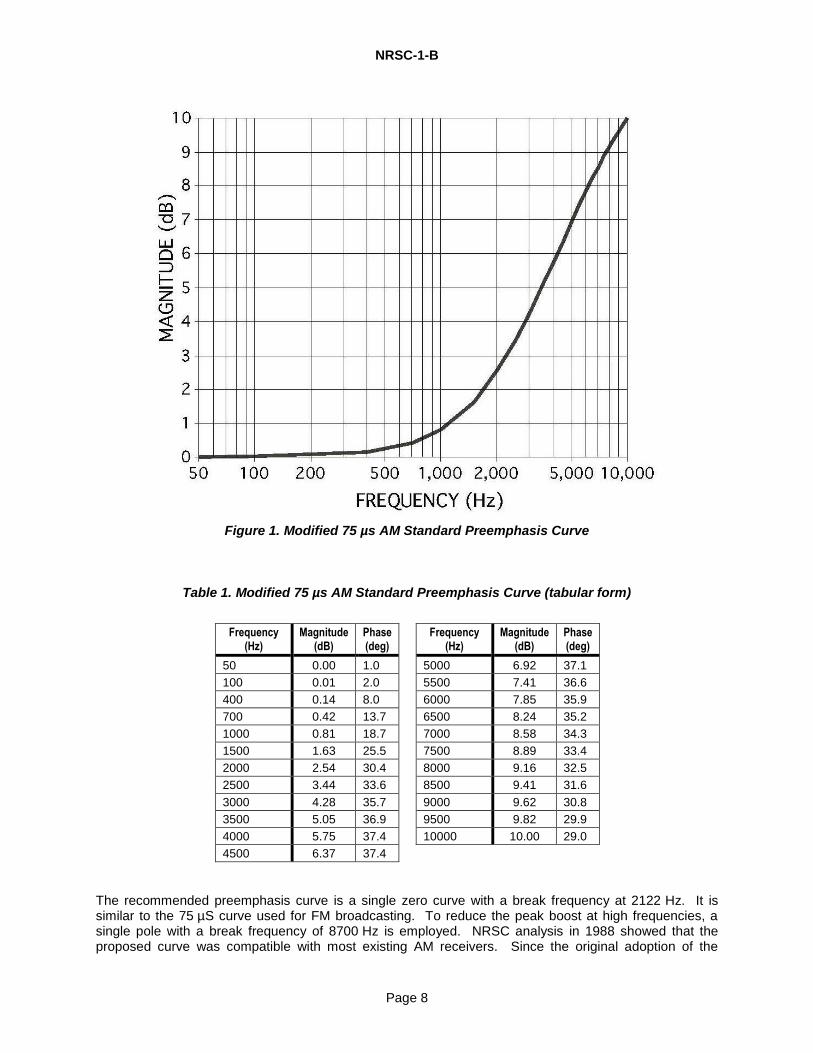
5.2 Description of the Modified 75 µs Preemphasis Curve Each AM broadcast station (whether analog mono, analog stereo, or hybrid AM IBOC) shall broadcast with (analog) audio preemphasis as close as possible (within the capabilities of the station’s transmission system) to the recommended standard, without exceeding it. The curve applies for audio frequencies up to 10 kHz. The NRSC standard AM transmission preemphasis curve is shown in Figure 1 and Table 1. The curve describes the recommended net transmission system static audio response of an AM station.
3 See informative reference [2].
NRSC-1-B
Page 8
Figure 1. Modified 75 µs AM Standard Preemphasis Curve
Table 1. Modified 75 µs AM Standard Preemphasis Curve (tabular form)
Frequency (Hz)
Magnitude (dB)
Phase (deg)
Frequency (Hz)
Magnitude (dB)
Phase (deg)
50 0.00 1.0 5000 6.92 37.1
100 0.01 2.0 5500 7.41 36.6
400 0.14 8.0 6000 7.85 35.9
700 0.42 13.7 6500 8.24 35.2
1000 0.81 18.7 7000 8.58 34.3
1500 1.63 25.5 7500 8.89 33.4
2000 2.54 30.4 8000 9.16 32.5
2500 3.44 33.6 8500 9.41 31.6
3000 4.28 35.7 9000 9.62 30.8
3500 5.05 36.9 9500 9.82 29.9
4000 5.75 37.4 10000 10.00 29.0
4500 6.37 37.4
The recommended preemphasis curve is a single zero curve with a break frequency at 2122 Hz. It is similar to the 75 µS curve used for FM broadcasting. To reduce the peak boost at high frequencies, a single pole with a break frequency of 8700 Hz is employed. NRSC analysis in 1988 showed that the proposed curve was compatible with most existing AM receivers. Since the original adoption of the
NRSC-1-B
Page 9
Standard the broadcast and consumer electronics industries have been aware of the specifications, which have fostered compliant AM broadcast devices over the subsequent years.
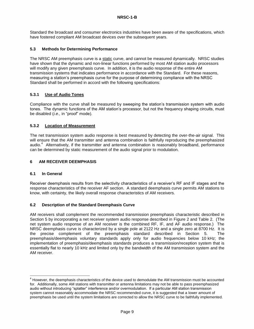
5.3 Methods for Determining Performance The NRSC AM preemphasis curve is a static curve, and cannot be measured dynamically. NRSC studies have shown that the dynamic and non-linear functions performed by most AM station audio processors will modify any given preemphasis curve. In addition, it is the audio response of the entire AM transmission systems that indicates performance in accordance with the Standard. For these reasons, measuring a station’s preemphasis curve for the purpose of determining compliance with the NRSC Standard shall be performed in accord with the following specifications:
5.3.1 Use of Audio Tones Compliance with the curve shall be measured by sweeping the station’s transmission system with audio tones. The dynamic functions of the AM station’s processor, but not the frequency shaping circuits, must be disabled (i.e., in “proof” mode).
5.3.2 Location of Measurement The net transmission system audio response is best measured by detecting the over-the-air signal. This will ensure that the AM transmitter and antenna combination is faithfully reproducing the preemphasized audio.
4 Alternatively, if the transmitter and antenna combination is reasonably broadband, performance
can be determined by static measurement of the audio signal prior to modulation.
6 AM RECEIVER DEEMPHASIS
6.1 In General Receiver deemphasis results from the selectivity characteristics of a receiver’s RF and IF stages and the response characteristics of the receiver AF section. A standard deemphasis curve permits AM stations to know, with certainty, the likely overall response characteristics of AM receivers.
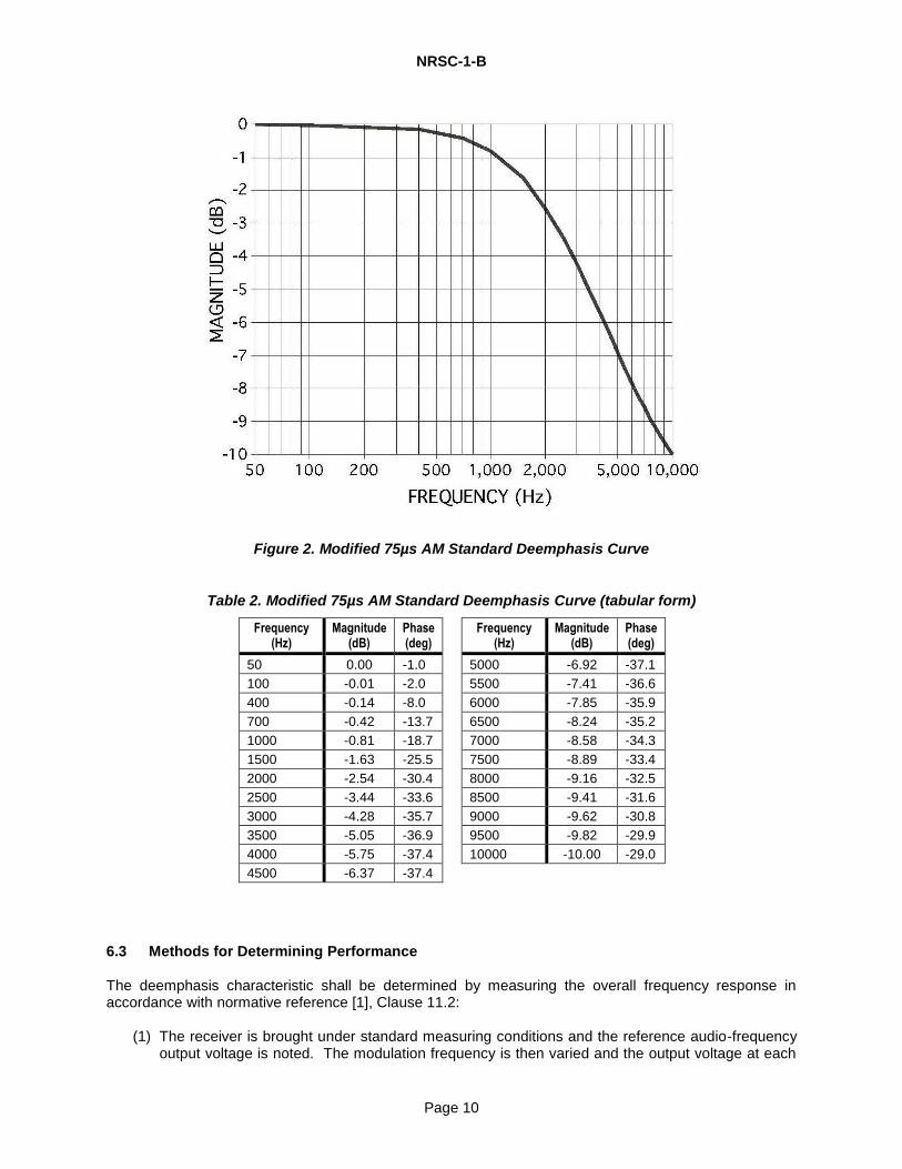
6.2 Description of the Standard Deemphasis Curve AM receivers shall complement the recommended transmission preemphasis characteristic described in Section 5 by incorporating a net receiver system audio response described in Figure 2 and Table 2. (The net system audio response of an AM receiver is the combined RF, IF, and AF audio response.) The NRSC deemphasis curve is characterized by a single pole at 2122 Hz and a single zero at 8700 Hz. It is the precise complement of the preemphasis standard described in Section 5. The preemphasis/deemphasis voluntary standards apply only for audio frequencies below 10 kHz; the implementation of preemphasis/deemphasis standards produces a transmission/reception system that is essentially flat to nearly 10 kHz and limited only by the bandwidth of the AM transmission system and the AM receiver.
4 However, the deemphasis characteristics of the device used to demodulate the AM transmission must be accounted
for. Additionally, some AM stations with transmitter or antenna limitations may not be able to pass preemphasized audio without introducing “splatter” interference and/or overmodulation. If a particular AM station transmission system cannot reasonably accommodate the NRSC recommended curve, it is suggested that a lower amount of preemphasis be used until the system limitations are corrected to allow the NRSC curve to be faithfully implemented.
NRSC-1-B
Page 10
Figure 2. Modified 75µs AM Standard Deemphasis Curve
Table 2. Modified 75µs AM Standard Deemphasis Curve (tabular form)
Frequency (Hz)
Magnitude (dB)
Phase (deg)
Frequency (Hz)
Magnitude (dB)
Phase (deg)
50 0.00 -1.0 5000 -6.92 -37.1
100 -0.01 -2.0 5500 -7.41 -36.6
400 -0.14 -8.0 6000 -7.85 -35.9
700 -0.42 -13.7 6500 -8.24 -35.2
1000 -0.81 -18.7 7000 -8.58 -34.3
1500 -1.63 -25.5 7500 -8.89 -33.4
2000 -2.54 -30.4 8000 -9.16 -32.5
2500 -3.44 -33.6 8500 -9.41 -31.6
3000 -4.28 -35.7 9000 -9.62 -30.8
3500 -5.05 -36.9 9500 -9.82 -29.9
4000 -5.75 -37.4 10000 -10.00 -29.0
4500 -6.37 -37.4
6.3 Methods for Determining Performance The deemphasis characteristic shall be determined by measuring the overall frequency response in accordance with normative reference [1], Clause 11.2:
(1) The receiver is brought under standard measuring conditions and the reference audio-frequency output voltage is noted. The modulation frequency is then varied and the output voltage at each
NRSC-1-B
Page 11
frequency is noted and expressed in decibels relative to the reference voltage. The modulation depth is adjusted at each frequency in accordance with the preemphasis
characteristic of AM broadcast transmission. To avoid overmodulation at some frequencies it may be necessary to use a modulation factor of less than 30% at some frequencies.
(2) If overloading of the AF section of the receiver occurs, either the volume control attenuation
should be increased or the modulation factor reduced, and a corresponding factor applied to the results.
(3) The measurements may be repeated with other values of RF input signal level and frequency.
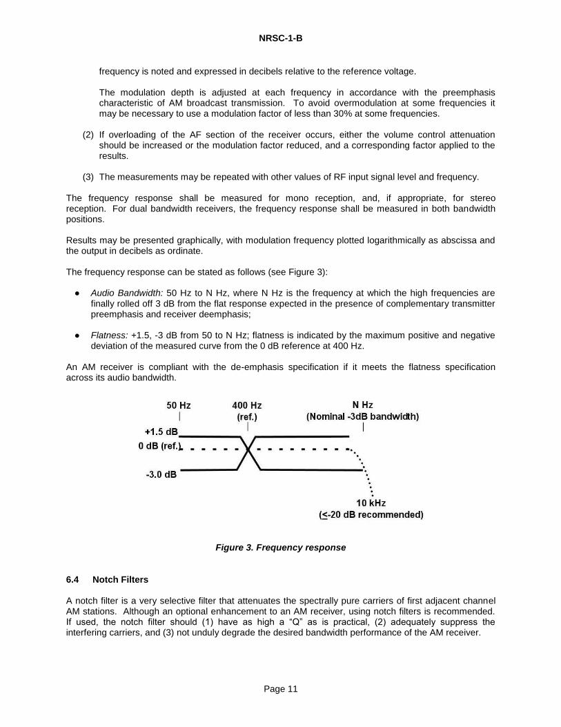
The frequency response shall be measured for mono reception, and, if appropriate, for stereo reception. For dual bandwidth receivers, the frequency response shall be measured in both bandwidth positions. Results may be presented graphically, with modulation frequency plotted logarithmically as abscissa and the output in decibels as ordinate. The frequency response can be stated as follows (see Figure 3):
● Audio Bandwidth: 50 Hz to N Hz, where N Hz is the frequency at which the high frequencies are finally rolled off 3 dB from the flat response expected in the presence of complementary transmitter preemphasis and receiver deemphasis;
● Flatness: +1.5, -3 dB from 50 to N Hz; flatness is indicated by the maximum positive and negative
deviation of the measured curve from the 0 dB reference at 400 Hz. An AM receiver is compliant with the de-emphasis specification if it meets the flatness specification across its audio bandwidth.
Figure 3. Frequency response
6.4 Notch Filters A notch filter is a very selective filter that attenuates the spectrally pure carriers of first adjacent channel AM stations. Although an optional enhancement to an AM receiver, using notch filters is recommended. If used, the notch filter should (1) have as high a “Q” as is practical, (2) adequately suppress the interfering carriers, and (3) not unduly degrade the desired bandwidth performance of the AM receiver.
NRSC-1-B
Page 12
7 AUDIO BANDWIDTH FOR AM TRANSMISSION
7.1 In General Each AM broadcast station (whether analog mono, analog stereo, or hybrid AM IBOC) shall modulate its transmitter with an (analog) audio bandwidth not exceeding that described by the specifications in this Section. Appropriate and carefully designed audio low-pass filters as the final filtering prior to modulation can be used to implement these specifications. The purpose of these bandwidth specifications is to remove interference by controlling the occupied RF bandwidth of AM stations.
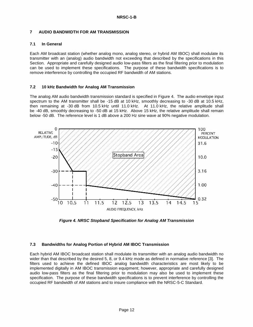
7.2 10 kHz Bandwidth for Analog AM Transmission The analog AM audio bandwidth transmission standard is specified in Figure 4. The audio envelope input spectrum to the AM transmitter shall be -15 dB at 10 kHz, smoothly decreasing to -30 dB at 10.5 kHz, then remaining at -30 dB from 10.5 kHz until 11.0 kHz. At 11.0 kHz, the relative amplitude shall be -40 dB, smoothly decreasing to -50 dB at 15 kHz. Above 15 kHz, the relative amplitude shall remain below -50 dB. The reference level is 1 dB above a 200 Hz sine wave at 90% negative modulation.
Figure 4. NRSC Stopband Specification for Analog AM Transmission
7.3 Bandwidths for Analog Portion of Hybrid AM IBOC Transmission Each hybrid AM IBOC broadcast station shall modulate its transmitter with an analog audio bandwidth no wider than that described by the desired 5, 8, or 9.4 kHz mode as defined in normative reference [3]. The filters used to achieve the defined IBOC analog bandwidth characteristics are most likely to be implemented digitally in AM IBOC transmission equipment; however, appropriate and carefully designed audio low-pass filters as the final filtering prior to modulation may also be used to implement these specification. The purpose of these bandwidth specifications is to prevent interference by controlling the occupied RF bandwidth of AM stations and to insure compliance with the NRSC-5-C Standard.
NRSC-1-B
Page 13
7.4 Method for Determining Performance An AM station is determined to be in compliance with the NRSC-1 audio bandwidth characteristic by measurement of the station’s audio bandwidth in accordance with the following parameters:
7.4.1 Analog AM Transmission
7.4.1.1 Location of Measurement
Audio bandwidth measurements shall be obtained at the audio input terminals to the AM transmitter. For AM stereo stations, audio bandwidth shall be measured at the L+R audio input terminals to the RF modulator. Note that the NRSC bandwidth Standard characterizes an audio bandwidth that represents station program material that has been modified by possibly non-linear circuits in the station’s audio processor. For this reason, the NRSC recommends use of a test signal that adequately characterizes typical audio program material, rather than relying on static audio test tones. However, it may still be useful to measure bandwidth statically at the time that AM preemphasis is measured.
7.4.1.2 Use of Standard Test Signal
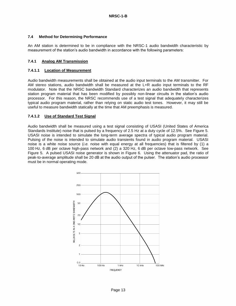
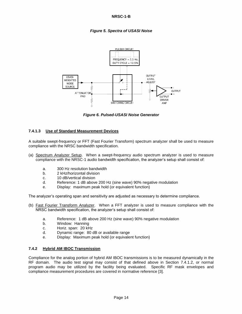
Audio bandwidth shall be measured using a test signal consisting of USASI (United States of America Standards Institute) noise that is pulsed by a frequency of 2.5 Hz at a duty cycle of 12.5%. See Figure 5. USASI noise is intended to simulate the long-term average spectra of typical audio program material. Pulsing of the noise is intended to simulate audio transients found in audio program material. USASI noise is a white noise source (i.e. noise with equal energy at all frequencies) that is filtered by (1) a 100 Hz, 6 dB per octave high-pass network and (2) a 320 Hz, 6 dB per octave low-pass network. See Figure 5. A pulsed USASI noise generator is shown in Figure 6. Using the attenuator pad, the ratio of peak-to-average amplitude shall be 20 dB at the audio output of the pulser. The station’s audio processor must be in normal operating mode.
NRSC-1-B
Page 14
Figure 5. Spectra of USASI Noise
Figure 6. Pulsed-USASI Noise Generator
7.4.1.3 Use of Standard Measurement Devices
A suitable swept-frequency or FFT (Fast Fourier Transform) spectrum analyzer shall be used to measure compliance with the NRSC bandwidth specification. (a) Spectrum Analyzer Setup. When a swept-frequency audio spectrum analyzer is used to measure
compliance with the NRSC-1 audio bandwidth specification, the analyzer’s setup shall consist of:
a. 300 Hz resolution bandwidth b. 2 kHz/horizontal division c. 10 dB/vertical division d. Reference: 1 dB above 200 Hz (sine wave) 90% negative modulation e. Display: maximum peak hold (or equivalent function)
The analyzer’s operating span and sensitivity are adjusted as necessary to determine compliance. (b) Fast Fourier Transform Analyzer. When a FFT analyzer is used to measure compliance with the
NRSC bandwidth specification, the analyzer’s setup shall consist of:
a. Reference: 1 dB above 200 Hz (sine wave) 90% negative modulation b. Window: Hanning c. Horiz. span: 20 kHz d. Dynamic range: 80 dB or available range e. Display: Maximum peak hold (or equivalent function)
7.4.2 Hybrid AM IBOC Transmission Compliance for the analog portion of hybrid AM IBOC transmissions is to be measured dynamically in the RF domain. The audio test signal may consist of that defined above in Section 7.4.1.2, or normal program audio may be utilized by the facility being evaluated. Specific RF mask envelopes and compliance measurement procedures are covered in normative reference [3].
NRSC-1-B
Page 15
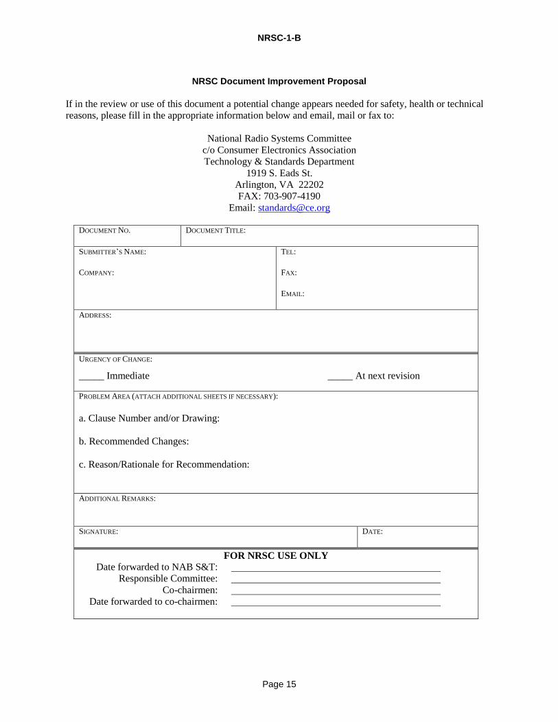
NRSC Document Improvement Proposal
If in the review or use of this document a potential change appears needed for safety, health or technical
reasons, please fill in the appropriate information below and email, mail or fax to:
National Radio Systems Committee
c/o Consumer Electronics Association
Technology & Standards Department
1919 S. Eads St.
Arlington, VA 22202
FAX: 703-907-4190
Email: [email protected]
DOCUMENT NO.
DOCUMENT TITLE:
SUBMITTER’S NAME:
COMPANY:
TEL:
FAX:
EMAIL:
ADDRESS:
URGENCY OF CHANGE:
_____ Immediate _____ At next revision
PROBLEM AREA (ATTACH ADDITIONAL SHEETS IF NECESSARY):
a. Clause Number and/or Drawing:
b. Recommended Changes:
c. Reason/Rationale for Recommendation:
ADDITIONAL REMARKS:
SIGNATURE:
DATE:
FOR NRSC USE ONLY
Date forwarded to NAB S&T:
Responsible Committee:
Co-chairmen:
Date forwarded to co-chairmen: