Embed Size (px)
Citation preview

ICS 13.340.50C 73
National Standard of the People’s Republic of China
GB ××××—200×
Personal protective equipment —Occupational Footwear
(ISO 20347: 2004, MOD)
(Draft for Approval) (Draft Completion on 29 March 2006)
Released: 200×-××-×× Enforced: 200×-××-××
Issued by General Administration of Quality Supervision, Inspection and Quarantine of the
People’s Republic of China


GB ××××—200×
Content
Foreword..............................................................................................................................................IIAppendix. A
(Specification appendix)Penetration Tests on Non-Metal Penetration-resistant Insert after Temperature Treatment and Chemical Treatment...................................................................................................................17
References..........................................................................................................................................19
I

GB ××××—200×
Foreword
Sections 5.3.1.2, 5.3.2, 5.4.3, 5.4.4, 5.4.5, 5.5.1, 5.5.2, 5.8.1, 5.8.2, 5.8.3, 5.8.4, 5.8.5 and 5.8.6 of this standard are mandatory. For additional provisions applicable to occupational footwear, the additional provisions are mandatory while the rest are recommendable.
This Standard is modified based on ISO 20347: 2004 “Personal Protective Equipment – Occupational Footwear” (English edition). This draft of this Standard is based on ISO 20347: 2004.
This Standard has the following modifications with comparison to ISO 20347:2004: —Transformation from international standard formats and statements into formats and statements
of the People’s Republic of China; editorial modifications based on Chinese language practices; some terminology and definitions are modified to meet with customary practices of the People’s Republic of China.
—ISO and EN forewords are deleted.—For scopes, additional regulations, together with applicable and non-applicable ranges, are
incorporated.—All ISO20344: 2004 quotations of the international standard are re-written as “GB/T××××—
200×”—All ISO 20347: 2004 footwear numbers are revised into corresponding international footwear
numbers and simplified as “Footwear Numbers”.—In Section 3.13, as regards the definition of conductive footwear, “resistance within
0Ω~100kΩ”is revised to “resistance < 100kΩ”.—In the definition of the antistatic footwear, “resistance value is above 100kΩ…” is revised to “the
resistance value is ≥ 100kΩ…”.—Deletion of “3.18, Terminology” of the international standard.—In 5.7.4.1, “abrasive damage shall not be more severe than that described of standard
specimens of similar materials” is revised to “shall not have severe abrasive damage”. —Deleted “The penetration-resistant insert shall not be placed above the curled edge of the safety
toecap, nor shall it come into contact with the safety toecap” from 6.2.1.2.—In 6.2.1.5.1, translated corresponding provisions of “EN12568 : 1998” quoted by the
international standard, and extended Appendix A for this purpose.—In 6.2.2.1, “resistance shall be no greater than 100kΩ” is revised to “resistance shall be less
than 100kΩ”.—In 6.2.2.2, “resistance shall be greater than 100kΩ” is revised to “resistance ≥ 100kΩ…”.—In 6.2.3.1, “30min later,” is inserted before “temperature rise on the surface of the inner
bottom…”.—In 6.4.1, deleted “with the exception of the area under the curled edge of the safety toecap”.—Deletion of 8.1b of the International Standard.—In 8.2.1, “… up-limit of value of the 100kΩ resistance” is revised to “… resistance is less than
100kΩ”.—In 8.2.3, “resistance” in c) is revised to “electrical property”; deletion of sub-item 2) of d);
cancellation of the serial indicator “1)”, the text of which is used as the direct content of the item d). —Content of references is increased according to the revision of this Standard.From the date of enforcement, this Standard replaces both GB4385—1995 and GB16756—1997.Appendix A of this Standard is a specification appendix. This Standard was proposed by the State Administration of Work Safety. This Standard is under the jurisdiction of the National Technical Committee of Standardisation for
Personal Protective Equipment (CSBTS/TC112). Drafting units of this Standard: Sinosteel Wuhan Safety & Environmental Protection Research
Institute; National Labour Protection Appliances Quality Supervision Inspection Centre (Wuhan); Guang Zhou OSH Safety Technology Ltd.; Saina Group Co., LTD., Zhe Jiang; Tianjin Shuangan Laobao
II

GB ××××—200×
Rubber Corporation.Major writers of this Standard: Cheng Jun, She Qi-Yuan, Liu Hong-Bin, Zhang Yuan-Hu, Liu Ju-
Yuan, Chen Tie.
III


GB ××××—200×
Personal Protective Equipment – Occupational Footwear
1 ScopeThis Standard sets the terms and definitions, classifications, basic and additional requirements,
labelling and available information concerning occupational footwear.This Standard is applicable to occupational footwear that protects the wearer’s feet and legs from
being injured by hazards of the workplace.This Standard is not applicable to occupational footwear without insole and insock, or without
insole but with removable insock.2 Specification-related references
The provisions of the following documents constitute the provisions of this Standard after being referenced. For dated reference documents, all later amendments (excluding corrigenda) and versions do not apply to this Standard; however it is encouraged to study with all agreed parties whether the latest versions of these documents are applicable. For non-dated reference documents, the latest versions apply to this Standard.
GB/T××××—200× Test Methods of Personal Protective equipment – Safety Footwear (ISO20344: 2004, MOD) 3 Terms and definitions
The following terms and definitions are applicable to this Standard.Note: Fig. 1 and Fig. 2 illustrate parts of footwear.
3.1Occupational footwearOccupational footwear is footwear with protective features but without safety toecaps and is used
to protect the wearer from accidental injuries.3.2
Leather3.2.1
Full grain leatherTanned leather that does not decay and that retains a full surface grain.
3.2.2Corrected grain leatherTanned leather that does not decay and whose surface grain structure has been modified by
mechanical processing. 3.2.3
Leather splitA layer of tanned, decay-preventive leather, attained by splitting a thick hide; normally an upper-
first or intermediate layer.3.3
RubberRubber refers to vulcanised rubber in this Standard.
3.4Polymeric materialsPolymeric materials refers to materials such as polyurethane or polyethylene (vinyl chloride).
3.5InsoleA non-moveable component, usually connected to the vamp in the shoe-making process, used to
form the bottom part of the shoe.3.6
1

GB ××××—200×
InsockThe moveable or fixed shoe element that covers the insole either partially or entirely.
3.7LiningThe material covering the inner surface of the upper.Note 1: The wearer’s foot comes in direct contact with the lining.Note 2: For shoes with a safety toecap, lining is installed where the fore-part of the vamp is cut open for
accommodating the safety toecap, or seamed onto the vamp to form a pocket for accommodating the safety toecap, so as to protect the material underneath the safety toecap.
3.7.1Vamp liningThe material that covers the inner surface of the front part of the upper (the vamp).
3.7.2Quarter liningThe material that covers the inner surface of the rear part of the upper (the quarter).
3.8Cleat(s)The protruding component on the outer surface of the sole.
3.9Rigid outsoleWhen the entire shoe is measured in accordance with 8.4.1 of GB/T××××—200×, a rigid outsole
shall be bent less than 45° when under a load of 30N.3.10
Cellular outsoleAn outsole structure with a density of 0.9g/cm2 or less, of which the porous structure is visible
under a 10X magnifier. 3.11
Penetration-resistant insertAn element inserted into the sole combination for providing the wearer with protection against
penetration.3.12
Seat regionThe rear part of the shoe (upper and sole).
3.13Conductive footwearFootwear with a resistance of less than 100kΩ, measured in accordance with 5.10 of GB/T××××—
200×.3.14
Antistatic footwearFootwear with a resistance of between 100kΩ – 1,000MΩ, measured in accordance with 5.10 of
GB/T××××—200×.3.15
Electrically insulating footwearFootwear that protects the wearer against electrical shocks, by blocking electric currents from
running through the wearer’s body.3.16
Fuel oil
2

GB ××××—200×
The aliphatic hydrocarbon content of petroleum.
1 - side sticker; 6 - pad; 11 - heel;2 - tongue; 7 - outsole; 12 - stitch-line between
insole and upper ;3 - collar; 8 - cleats; 13 - quarter;4 - upper; 9 - penetration-resistant
insert;14 - vamp.
5 - vamp lining; 10 - insole;
Fig. 1a) Insole and Upper are parts of a seamed shoe structure
3
GB ××××—200×
1 - upper; 3 - tacked side reinforcement band; 5 - wooden sole.2 - rigid sole; 4 - outsole;
Fig. 1b) Parts of the traditional shoe structure
1 - Upper; 2 - Vamp; 3 - Outsole; 4 - Heel.
Fig. 2 All-rubber (i.e. vulcanised) or all polymer (i.e. fully moulded) shoes
4 CategoriesShoes are categorised in Table 1
4
GB ××××—200×
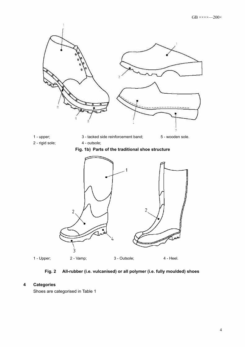
Table 1 Shoe categoriesSpecification Number Category
I Shoes made of leather or other materials, with the exception of all-rubber or all-polymer.
II All-rubber (i.e. fully vulcanised) or all polymer (i.e. fully moulded) shoes
1 - Any extension that fits the wearer;A - Low cut shoe;B - Ankle boot;C - Half calf boot;D - Calf boot;E - Knee boot.Note: Style E is a calf boot (style D) with an added extended upper made of non-permeable material, with
a cutout that fits to the wearer’s leg.
Fig. 3 Footwear Styles
5 Basic requirements for occupational footwear5.1 General requirements
Occupational Footwear shall comply with the basic requirements given in Table 2 and any of the five options given in Table 3, plus at least 1 of the basic requirements for finished footwear given in Table 12.
5

GB ××××—200×
Table 2 Occupational Footwear - basic requirements
Requirements Provision CategoryI II
Style
Height of upper 5.2.1 × ×Seat region: 5.2.2
Style A ×Styles B, C, D, E × ×
Finished footwear
Sock properties: 5.3.1Structure 5.3.1.1 ×Upper/outsole binding strength
5.3.1.2 ×
Leak resistance 5.3.2 ×Specific ergonomic features
5.3.3 × ×
Upper
General requirements 5.4.1 × ×Thickness 5.4.2 ×Tear strength 5.4.3 ×Tensile properties 5.4.4 × ×Flex resistance 5.4.5 ×Steam permeability and steam coefficient
5.4.6 ×
pH value 5.4.7 ×Hydrolysis 5.4.8 ×Hexavalent chromium 5.4.9 ×
Vamp Lining
Tear strength 5.5.1 ×Wear resistance 5.5.2 ×Steam permeability and coefficient
5.5.3 ×
pH value 5.5.4 ×Hexavalent chromium content
5.5.5 ×
Quarter Lining
Tear strength 5.5.1 ○Wear resistance 5.5.2 ○Steam permeability and steam coefficient
5.5.3 ○
pH value 5.5.4 ○Hexavalent chromium content
5.5.5 ○
Tongue
Tear strength 5.6.1 ○pH value 5.6.2 ○Hexavalent chromium content
5.6.3 ○
Outsole
Thickness of non-slip outsole
5.8.1 × ×
Tear strength 5.8.2 ×Wear resistance 5.8.3 × ×Flex resistance 5.8.4 × ×Hydrolysis 5.8.5 × ×Binding strength of intermediate layers
5.8.6 ○ ○
Note: the requirements listed in this table are applicable to a specific category as follows:× The requirements shall be complied with. In certain cases, requirements only pertain to materials in a
specific range – such as the pH value of leather parts. This does not mean that other materials are not applicable.
○ Total compliance if the part exists. No × or ○ indication means no such requirement.
6

GB ××××—200×
Table 3 Option of Basic Requirements in the Insole and/or Insock
Option Evaluated Parts
Conformity Requirements
Thickness5.7.1
PH Valuea
5.7.2
Water absorbance
and hydrolysis tendency
5.7.3
Wear 5.7.4.1
Hexavalent chromium contenta
5.7.5
Wear5.7.4.2
1No insole or insole does not comply
Non-movable insock Insock × × × × ×
234
5
With Insole
No insockWith insock
seatInsole × × × × ×
Non-movable full insock
Insock with Insole × ×
Insock × × ×Movable and
permeableb full insock
Insole × × × × ×
Insock × × ×
Movable and non-permeableb
full insock
Insole × × × × ×
Insock × × × ×
× Indicates that the requirement must be complied with.Note: See 8.3 for movable insole.
a Applicable to leather parts onlyb Permeable insock refers subject to water permeation within 60 seconds or under in accordance with 7.2 of
GB/T××××—200×.5.2 Style
The footwear shall comply with any of the styles given in Fig.3.5.2.1 Height of the upper
The height of the footwear upper shall comply with requirements listed in Table 4 in accordance with the methods specified in 6.2 of GB/T××××—200×.
Table 4 Footwear Upper Height
Footwear NumberHeight(mm)
Style A Style B Style C Style D≤ 225 < 103 ≥ 103 ≥ 162 ≥ 255
230~240 < 105 ≥ 105 ≥ 165 ≥ 260245~250 < 109 ≥ 109 ≥ 172 ≥ 270255~265 < 113 ≥ 113 ≥ 178 ≥ 280270~280 < 117 ≥ 117 ≥ 185 ≥ 290
≥ 285 < 121 ≥ 121 ≥ 192 ≥ 3005.2.2 Seat Region
The seat region shall be closed.5.3 Finished footwear5.3.1 Properties of soles5.3.1.1 Structure
If present, the insole shall be immovable unless the footwear is damaged.5.3.1.2 Binding strength between upper and outsole.
With the exception of seamed soles, the binding strength shall be ≥ 4.0N/mm, when tested, in accordance with the method stipulated in 5.2 of GB/T××××—200×; in the case of a tear in the sole, the binding strength shall be ≥ 3.0N/mm.5.3.2 Leak Resistance
When measured in accordance with the methods specified in 5.7 of GB/T××××—200×, no air leakage shall occur.5.3.3 Specific ergonomic features
7
GB ××××—200×
If all of the questions in 5.1 of GB/T××××—200× are answered with YES, the footwear shall be deemed as conforming to the ergonomic requirements.5.4 Footwear upper5.4.1 General requirements
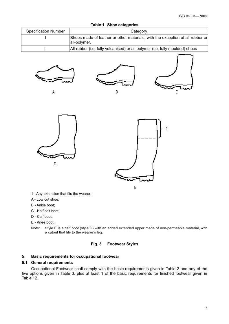
For styles B, C, D and E, the minimum height measured from the elevation of the sole in the area that meets with requirements for the upper shall meet with the requirements set out in Table 5.
Table 5 The minimum height of upper that fully complies with upper requirements
Footwear NumberMinimum Height
mmStyle B Style C Style D Style E
≤225 (64 (113 (172 (265230~240 (66 (115 (175 (270
245~250 (68 (119 (182 (280255~265 (70 (123 (188 (290
270~280 (72 (127 (195 (300(285 (73 (131 (202 (310
In the case of the collar and lining being located at a height that exceeds those listed in Table 5, these materials shall conform to tear strength (5.5.1) and wear resistance (5.5.2) of the lining material; for leather materials, additional requirements shall comply with the pH value (5.4.7) and hexavalent chromium content (5.4.9).5.4.2 Thickness
When measured in accordance with the methods specified in 6.1 of GB/T××××—200×, the thickness of Category II footwear upper at any position shall comply with the requirements set out in Table 6.
Table 6 Minimum Thickness of Upper
Type of MaterialThickness
mm
Rubber (1.50Polymer (1.00
5.4.3 Tear strengthWhen measured in accordance with the methods specified in 6.3 of GB/T××××—200×, the
tear strength of Category I footwear upper shall comply with the requirements ser out in Table 7.Table 7 Tear Strength of Upper
Type of Material Minimum ForceN
Leather ≥120Coated fabric/textile ≥60
5.4.4 Tensile propertiesWhen measured in accordance with the methods specified in 6.4 of GB/T××××—200×, tensile
properties shall comply with the requirements set out in Table 8. Table 8 Tensile Properties
Type of material Tensile strengthN/mm2
Tear StrengthN
100% Fixed Elongation stress
N/mm2
Elongation at break%
Split Leather ≥15 —— —— ——Rubber —— ≥180 —— ——Polymer —— —— 1.3~4.6 ≥250
5.4.5 Flex resistanceWhen measured in accordance with the methods specified in 6.5 of GB/T××××—200×, flex
resistance shall comply with the requirements set out in Table 9. Table 9 Flex Resistance
8

GB ××××—200×
Type of material Flex ResistanceRubber No crack shall occur after 125,000 successive bendings.Polymer No crack shall occur after 150,000 successive bendings.
5.4.6 Steam permeability and coefficientWhen measured in accordance with the methods specified in 6.6 and 6.8 of GB/T××××—200×,
Steam permeability shall be no less than 0.8mg/ (cm2·h); steam coefficient shall be no less than 15mg/cm2. 5.4.7 pH Value
When measured in accordance with the methods specified in 6.9 of GB/T××××—200×, the pH value of the leather upper shall be no less than 3.2. If the pH value is less than 4, the dilution difference shall be less than 0.7.5.4.8 Hydrolysis
When tested in accordance with the methods specified in 6.10 of GB/T××××—200×, cracks shall not occur after 150,000 successive bendings of the polyurethane upper5.4.9 Hexavalent Chromium content
When measured in accordance with the methods specified in 6.11 of GB/T××××—200×, no hexavalent chromium shall be found in the leather Upper.5.5 Lining
The following requirements are applicable to the vamp lining and quarter lining.5.5.1 Tear strength
When measured in accordance with the methods specified in 6.3 of GB/T××××—200×, the tear strength of the lining shall comply with the requirements set out in Table 10.
Table 10 Lining tear strength
Type of Material Minimum ForceN
Leather ≥30Coated fabric/textile ≥15
5.5.2 Wear resistanceWhen measured in accordance with the methods specified in 6.12 of GB/T××××—200×, no
rupture shall occur in the lining on completion of the following number of revolutions: - dry test: 25,600 turns;- wet test: 12,800 turns.
5.5.3 Steam permeability and coefficientWhen measured in accordance with the methods specified in 6.6 and 6.8 of GB/T××××—200×,
steam permeability shall be no less than 2.0mg/ (cm2·h); steam coefficient shall be no less than 20mg/cm2.
Note: Not applicable to non-textured hard lining.
5.5.4 pH ValueWhen measured in accordance with the methods specified in 6.9 of GB/T××××—200×, the pH
value of a leather lining shall be no less than 3.2. If the pH value is less than 4, the dilution difference shall be less than 0.7.5.5.5 Hexavalent Chromium content
When measured in accordance with the methods specified in 6.11 of GB/T××××—200×, no hexavalent chromium shall be found in the leather lining.5.6 Tongue
Tests shall be performed only if the tongue material or thickness of the tongue is different to that of Upper.5.6.1 Tear strength
When measured in accordance with the methods specified in 6.3 of GB/T××××—200×, the tear strength of tongue shall comply with the requirements set out in Table 11.
Table 11 Tear Strength of Tongue
9

GB ××××—200×
Type of material Minimum forceN
Leather ≥36Coated fabric/textile ≥18
5.6.2 pH ValueWhen measured in accordance with the methods specified in 6.9 of GB/T××××—200×, the pH
value of a leather tongue shall be no less than 3.2. If the pH value is less than 4, the dilution difference shall be less than 0.7.5.6.3 Hexavalent Chromium content
When measured in accordance with the methods specified in 6.11 of GB/T××××—200×, no hexavalent chromium shall be found in the leather tongue.5.7 Insole and insock5.7.1 Thickness
When measured in accordance with the methods specified in 7.1 of GB/T××××—200×, the thickness of insole shall be no less than 2.0mm.5.7.2 pH Value
When measured in accordance with the methods specified in 6.9 of GB/T××××—200×, pH value of the leather insole or insock shall be no less than 3.2. If the pH value is less than 4, the dilution difference shall be less than 0.7.5.7.3 Water absorbance and hydrolysis tendency
When measured in accordance with the methods specified in 7.2 of GB/T××××—200×, water absorbance shall be no less than 70mg/cm2 and hydrolysis tendency shall be no less than 80% of the absorbed water.5.7.4 Wear resistance5.7.4.1 Insole
When tested in accordance with the methods specified in 7.3 of GB/T××××—200×, no severe wear shall occur on completion of 400 cycles.5.7.4.2 Insock
When tested in accordance with the methods specified in 6.12 of GB/T××××—200×, no rupture shall occur on any abrasive surface on completion of the following number of cycles.
- Dry test: 25,600 cycles;- Wet test: 12,800 cycles.
5.7.5 Hexavalent Chromium contentWhen measured in accordance with the methods specified in 6.11 of GB/T××××—200×, no
hexavalent chromium shall be found in the leather insole.5.8 Outsole5.8.1 Non-slip outsole
When measured in accordance with the methods specified in 8.1 of GB/T××××—200×, the thickness of the non-slip outsole shall be no less than 6mm at any location.5.8.2 Tear strength
When measured in accordance with the methods specified in 8.2 of GB/T××××—200×, tear strength shall be no less than:
- 8kN/m, applicable to materials having a density >0.9g/cm3. - 5kN/m, applicable to materials having a density ≤0.9g/cm3.
5.8.3 Wear resistanceWhen measured in accordance with the methods specified in 8.3 of GB/T××××—200×, non-leather
outsoles (with the exception of full rubber and full polymer) with a density ≤0.9g/cm3 shall have a relative wear of no more than 250mm3 per unit volume; and with a density > 0.9g/cm3 shall have a relative wear of no more than 150mm3 per unit volume.
When measured in accordance with the methods specified in 8.3 of GB/T××××—200×, full rubber
10

GB ××××—200×
and full polymer outsoles shall have a relative wear of no more than 250mm3 per unit volume.5.8.4 Flex resistance
When measured in accordance with the methods specified in 8.4 of GB/T××××—200×, elongation of the cut notch shall not exceed 4mm after 30,000 successive bendings.5.8.5 Hydrolysis
When measured in accordance with the methods specified in 8.5 of GB/T××××—200×, elongation of the cut notch shall not exceed 6mm after 150,000 successive bendings of the polyurethane outsole and the polyurethane bottom outer layer of the footwear. 5.8.6 Binding strength in the intermediate binding layer
When measured in accordance with the methods specified in 5.2 of GB/T××××—200×, binding strength between the outer layer or non-slip layer and its subsequent layer shall be no less than 4.0N/mm; in the case of a rupture to the bottom of the footwear, the binding strength shall be no less than 3.0N/mm.6 Additional Occupational Footwear requirements6.1 General requirements
Occupational footwear applicable to different hazards found in the workplace shall comply with additional requirements and corresponding markings as listed in Table 12.
Table 12 Additional requirements with proper markings for specific uses
Requirement Provision CategoryI II Marking
Finished Footwear
Resistance to penetration 6.2.1 × × P
Electrical properties: 6.2.2Conductive footwear 6.2.2.1 × × CAntistatic footwear 6.2.2.2 × × AInsulating footwear 6.2.2.3 × I
Resistance to severe environment conditions:
6.2.3
Thermal insulation of the sole 6.2.3.1 × × HI
Protection of the sole against cold 6.2.3.2 × × CI
Energy absorption in seat region 6.2.4 × × E
Waterproof 6.2.5 × WRAnkle protection 6.2.6 × × AN
UpperPermeability and water absorption 6.3.1 × WRU
Structure 6.3.2 ×
Outsole
Non-slip area: 6.4.1 × ×Thickness of Non-slip outsole 6.4.2 × ×
Height of cleats 6.4.3 × ×Resistance to heat contact 6.4.4 × × HRO
Oil resistance 6.4.5 × × FONote: Note: the requirements listed in this table are applicable to a specific category as follows:× The requirement shall be complied with if the feature in question exists.6.2 Finished Footwear6.2.1 Prevention against penetration6.2.1.1 Penetrating force
When measured in accordance with the methods specified in 5.8.2 of GB/T××××—200×, the force required to penetrate the outsole shall be no less than 1,100N.6.2.1.2 Structure
A penetration-resistant insert shall be placed inside the bottom of the footwear, and the insert shall not be moved unless the footwear is damaged.
11
GB ××××—200×
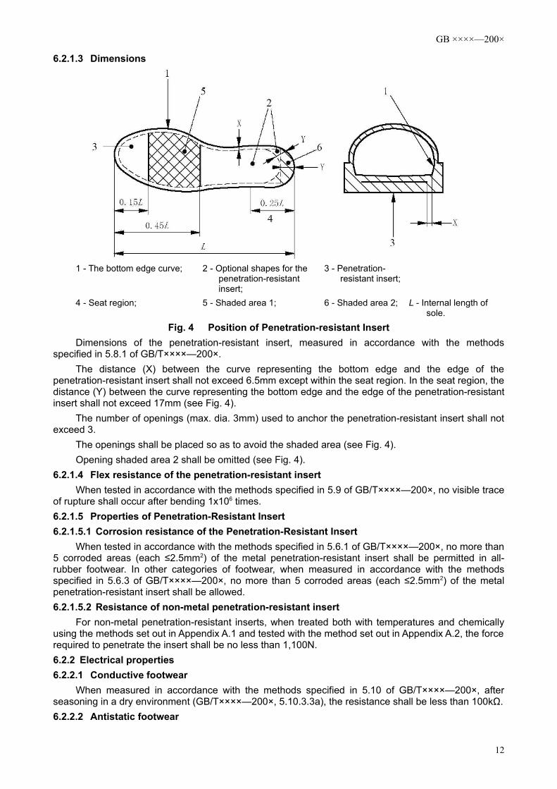
6.2.1.3 Dimensions
1 - The bottom edge curve; 2 - Optional shapes for the penetration-resistant insert;
3 - Penetration-resistant insert;
4 - Seat region; 5 - Shaded area 1; 6 - Shaded area 2; L - Internal length of sole.
Fig. 4 Position of Penetration-resistant InsertDimensions of the penetration-resistant insert, measured in accordance with the methods
specified in 5.8.1 of GB/T××××—200×.The distance (X) between the curve representing the bottom edge and the edge of the
penetration-resistant insert shall not exceed 6.5mm except within the seat region. In the seat region, the distance (Y) between the curve representing the bottom edge and the edge of the penetration-resistant insert shall not exceed 17mm (see Fig. 4).
The number of openings (max. dia. 3mm) used to anchor the penetration-resistant insert shall not exceed 3.
The openings shall be placed so as to avoid the shaded area (see Fig. 4).Opening shaded area 2 shall be omitted (see Fig. 4).
6.2.1.4 Flex resistance of the penetration-resistant insertWhen tested in accordance with the methods specified in 5.9 of GB/T××××—200×, no visible trace
of rupture shall occur after bending 1x106 times.6.2.1.5 Properties of Penetration-Resistant Insert6.2.1.5.1 Corrosion resistance of the Penetration-Resistant Insert
When tested in accordance with the methods specified in 5.6.1 of GB/T××××—200×, no more than 5 corroded areas (each ≤2.5mm2) of the metal penetration-resistant insert shall be permitted in all-rubber footwear. In other categories of footwear, when measured in accordance with the methods specified in 5.6.3 of GB/T××××—200×, no more than 5 corroded areas (each ≤2.5mm2) of the metal penetration-resistant insert shall be allowed.6.2.1.5.2 Resistance of non-metal penetration-resistant insert
For non-metal penetration-resistant inserts, when treated both with temperatures and chemically using the methods set out in Appendix A.1 and tested with the method set out in Appendix A.2, the force required to penetrate the insert shall be no less than 1,100N.6.2.2 Electrical properties6.2.2.1 Conductive footwear
When measured in accordance with the methods specified in 5.10 of GB/T××××—200×, after seasoning in a dry environment (GB/T××××—200×, 5.10.3.3a), the resistance shall be less than 100kΩ.6.2.2.2 Antistatic footwear
12

GB ××××—200×
When measured in accordance with the methods specified in 5.10 of GB/T××××—200×, after seasoning in a dry environment and a moisturised environment (GB/T××××—200×, 5.10.3.3a and b), resistance shall be ≥ 100kΩ or ≤ 1,000MΩ.6.2.2.3 Electrically insulating footwear
When measured in accordance with the methods specified in 5.11 of GB/T××××—200×, the footwear shall comply with category 0 or category 00 requirements.6.2.3 Resistance against severe environmental conditions6.2.3.1 Thermal insulation of the sole
When measured in accordance with the methods specified in 5.12 of GB/T××××—200×, the temperature rise in the upper surface of the insole shall not exceed 22°C after a 30 minute test, and the sole shall have no deformation or brittling that may deteriorate the functions of the sole.
The thermal insulating layer installed inside the footwear shall not be moveable unless the footwear is damaged.6.2.3.2 Protection of the sole against cold
When measured in accordance with the methods specified in 5.13 of GB/T××××—200×, the temperature drop on the upper surface of the insole shall not exceed 10°C.
The thermal insulating layer installed inside the footwear shall not be moveable unless the footwear is damaged.6.2.4 Energy absorption at the seat region
When measured in accordance with the methods specified in 5.14 of GB/T××××—200×, energy absorption at the seat region shall be no less than 20J.6.2.5 Waterproof
When measured in accordance with the methods specified in 5.15.1 of GB/T××××—200×, the total area of infiltration after walking through 100 lengths of the (test) tank, shall not exceed 3cm2; or, when measured in accordance with the methods specified in 5.15.2 of GB/T××××—200×, no water penetration shall occur after 15min.6.2.6 Ankle Protection
When tested in accordance with the methods specified in 5.17 of GB/T××××—200×, the mean of the test results shall not exceed 20kN and each individual test result shall not exceed 30kN.6.3 Upper6.3.1 Permeability and water absorption
When measured in accordance with the methods specified in 6.13 of GB/T××××—200×, permeability (expressed as mass increase of the absorbing cloth after 60 min) shall not exceed 0.2g; water absorption ratio shall not exceed 30%.6.3.2 Structure
Non-functional decorative stitching or perforations shall not be made on footwear whose upper has waterproof requirements.6.4 Outsole6.4.1 Non-slip area
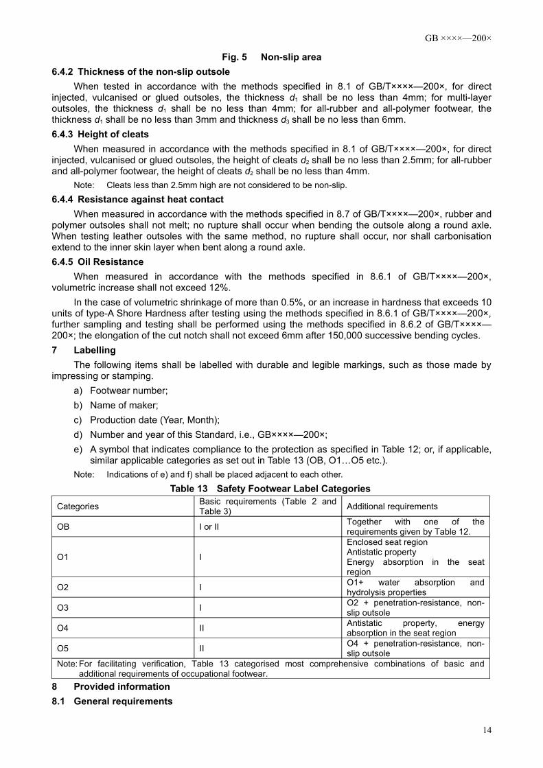
Beside the area underneath the curled rim of the safety toecap, the areas shown in Fig. 5 at a minimum shall be provided with cleats that run towards the sides.
13
GB ××××—200×
Fig. 5 Non-slip area6.4.2 Thickness of the non-slip outsole
When tested in accordance with the methods specified in 8.1 of GB/T××××—200×, for direct injected, vulcanised or glued outsoles, the thickness d1 shall be no less than 4mm; for multi-layer outsoles, the thickness d1 shall be no less than 4mm; for all-rubber and all-polymer footwear, the thickness d1 shall be no less than 3mm and thickness d3 shall be no less than 6mm.6.4.3 Height of cleats
When measured in accordance with the methods specified in 8.1 of GB/T××××—200×, for direct injected, vulcanised or glued outsoles, the height of cleats d2 shall be no less than 2.5mm; for all-rubber and all-polymer footwear, the height of cleats d2 shall be no less than 4mm.
Note: Cleats less than 2.5mm high are not considered to be non-slip.
6.4.4 Resistance against heat contactWhen measured in accordance with the methods specified in 8.7 of GB/T××××—200×, rubber and
polymer outsoles shall not melt; no rupture shall occur when bending the outsole along a round axle. When testing leather outsoles with the same method, no rupture shall occur, nor shall carbonisation extend to the inner skin layer when bent along a round axle.6.4.5 Oil Resistance
When measured in accordance with the methods specified in 8.6.1 of GB/T××××—200×, volumetric increase shall not exceed 12%.
In the case of volumetric shrinkage of more than 0.5%, or an increase in hardness that exceeds 10 units of type-A Shore Hardness after testing using the methods specified in 8.6.1 of GB/T××××—200×, further sampling and testing shall be performed using the methods specified in 8.6.2 of GB/T××××—200×; the elongation of the cut notch shall not exceed 6mm after 150,000 successive bending cycles.7 Labelling
The following items shall be labelled with durable and legible markings, such as those made by impressing or stamping.
a) Footwear number;b) Name of maker;c) Production date (Year, Month);d) Number and year of this Standard, i.e., GB××××—200×;e) A symbol that indicates compliance to the protection as specified in Table 12; or, if applicable,
similar applicable categories as set out in Table 13 (OB, O1…O5 etc.).Note: Indications of e) and f) shall be placed adjacent to each other.
Table 13 Safety Footwear Label Categories
Categories Basic requirements (Table 2 and Table 3) Additional requirements
OB I or II Together with one of the requirements given by Table 12.
O1 I
Enclosed seat regionAntistatic propertyEnergy absorption in the seat region
O2 I O1+ water absorption and hydrolysis properties
O3 I O2 + penetration-resistance, non-slip outsole
O4 II Antistatic property, energy absorption in the seat region
O5 II O4 + penetration-resistance, non-slip outsole
Note: For facilitating verification, Table 13 categorised most comprehensive combinations of basic and additional requirements of occupational footwear.
8 Provided information8.1 General requirements
14

GB ××××—200×
The following information shall be given:a) Name and full address of the maker and/or its fully authorised agent;b) Number and year of Standardc) Description of any hieroglyph, label and performance level. Basic descriptions applicable to
footwear tests (if any). d) Instructions for use:
i. If necessary, tests by the wearer shall be performed and passed prior to use;ii. If applicable, instructions on putting-on and taking-off the footwear;iii. Basic information for use, and detailed sources of such information.iv. Limitations for use (such as temperature range, etc.);v. Instructions on storage and maintenance, the maximum period for maintenance and
inspection (with detailed drying procedures if critical); vi. Cleaning and/or sterilisation instructions; vii. Expiry date or expiry period;viii. If applicable, warnings for potential problems are provided (any alteration may void the
certified category, such as footwear for cosmetic surgery);ix. If of use, examples, sections, digits, etc. are included.
e) Parts and spare parts are referenced (if relevant);f) Type of packaging suitable for transportation (if relevant).
8.2 Electrical properties8.2.1 Electrically conductive footwear
An instruction with the following text shall be provided with every pair of electrically conductive footwear:
“If static electricity is required to be charged to a minimum in the shortest possible period of time, e.g. for handling explosives, conductive footwear shall be used. When all risks of electrical shock by any electrical appliance or equipment have been eliminated, the conductive footwear is no longer required to be used. To ensure that the footwear is conductive, the new footwear must have a resistance of less than 100kΩ.
During the period of use, significant deviation in resistance may occur in footwear made of conductive material due to bending and pollution. The design function of static charge dispersion must therefore be maintained throughout the entire validity period. The user is therefore recommended to set up an internal resistance tester, at the required location, and to use it regularly. This test, together with the below-mentioned test, shall be incorporated as part of the routing procedures of the accident prevention programme in the working area.
If the footwear is worn in locations where the resistance of the sole material may be increased by pollutants, the wearer shall regularly check the resistance of his/her footwear every time he/she enters the risk area.
In locations where conductive footwear is used, the surface resistance of the ground shall not render the protection provided by the footwear ineffective.
When in use, no insulating part shall exist between the insole and the wearer’s foot, with the exception of an ordinary sock. If an insock exists between the insole and the wearer’s foot, the resistance of the shoe/sole assembly shall be checked.”8.2.2 Antistatic footwear
An instruction with the following text shall be provided with every pair of antistatic footwear:“If static electricity accumulation is required to be eliminated to a minimum by dispersing the static
charge, so as to prevent the risk of igniting flammable materials or vapour by a spark and, at the same time, if the risk of electric shock caused by any electrical appliance or equipment has not been fully eliminated, antistatic footwear must be used. However, it is reminded that antistatic footwear only forms a resistance between the foot and the ground; it does not guarantee adequate protection against electrical shock. If the risk of electrical shock has not been fully eliminated, additional measures to prevent such risks are crucial. Such additional measures, together with the additional below-mentioned
15

GB ××××—200×
tests, shall be incorporated as part of the routing procedures of the accident prevention programme in the working area.
Experience shows that for antistatic footwear a resistance of less than 1,000MΩ shall be measured in any discharging route of the product at any time during the entire validity period of the footwear. When operating at a voltage of up to 250V, the minimum resistance of new footwear for providing a limited amount of protection against electrical shock or fire in the case of failure of any failure electrical appliances is specified as 100kΩ. However, the wearer is made aware that in certain conditions the footwear may provide insufficient protection, and additional measures should always be provided to protect the wearer.
Significant deviation in resistance may occur in footwear of this kind due to bending and pollution. The footwear may not deliver the expected function if worn in wet conditions. Therefore the design function for dispersing the static charge must be maintained throughout the entire validity period, and at the same time provided with some protection. It is recommended that the user set up an internal resistance tester and use it regularly.
If the wearing period is extended, Category I footwear will absorb moisture and become conductive in wet conditions.
If the footwear is worn in locations where the sole material may be contaminated, the wearer shall regularly check the resistance of his/her footwear every time he/her enters the risk area.
In locations where antistatic footwear is used, the surface resistance of the ground shall not render the protection provided by the footwear ineffective.
During use, no insulating part shall exist between the insole and the wearer’s foot, with the exception of an ordinary sock. If an insock exists between the insole and the wearer’s foot, the resistance of the shoe/sole assembly shall be checked.”8.2.3 Electrically insulating footwear
Footwear with electrical insulation properties provides limited protection against accidental contact with faulty electrical appliances. Therefore an instruction with the following text shall be provided with each pair of electrically insulating footwear:
a) Electrically insulating footwear shall be used if there is a risk of electric shock, such as that caused by a damaged live instrument.
b) Electrically insulating footwear does not provide 100% protection against electric shock, and additional measures to prevent such risks are necessary. Such additional measures, together with the below-mentioned additional tests, shall be incorporated as a part of the routing procedures of the accident prevention programme in the working area.
c) Electrical properties of the footwear shall comply at all times with 6.2.2.3 requirements during the validity period.
d) During the period of use, the level of protection may be impaired by scratches, cuts, wearing-out or chemical pollution. Regular checks shall be performed and damaged footwear shall no longer be used.
e) When used in locations in which the material of the sole may be contaminated, such as by chemicals, a warning shall be given when entering into such locations, stating that the area may affect the electrical properties of the footwear.
f) It is recommended that the user set up an appropriate means for checking and testing the use of electrically insulating footwear.
8.3 InsockIf a moveable insock is provided, the instructions shall explain that the test is to be performed with
the insock appropriately positioned. A warning shall be provided explaining that the footwear shall be used once the insock has been properly positioned, and that the insock shall only be replaced by an equivalent insock provided by the original footwear manufacturer.
If no insock is provided, the instructions shall explain that the test shall be performed with no insock. The instructions shall include the warning that installing an insock may affect the protective features of the footwear.
16

GB ××××—200×
Appendix. A(Specification appendix)
Penetration Tests on Non-Metal Penetration-resistant Insert after Temperature Treatment and Chemical Treatment
A.1 (High/Low) Temperature Treatment and Chemical TreatmentA.1.1 High-temperature Treatment
Remove penetration-resistant insert, stick a thermocouple (with ±0.5°C accuracy) onto the surface of the insert; place the insert into an oven at (60±2) °C for 4 hours then remove it from the oven and allow it to cool down to (40±2) °C. Test immediately using the method(s) set out in A.2.
A.1.2 Low-temperature TreatmentRemove penetration-resistant insert, stick a thermocouple (with ±0.5°C accuracy) onto the surface
of the insert; place the insert into a refrigerating box at (-20±2) °C for 4 hours, then remove it. When the temperature reaches (-1±1) °C test immediately using the method(s) set out in A.2.
A.1.3 Acid TreatmentImmerse one penetration-resistant insert into l mol/l sulphuric acid solution at (20±2) °C for 24h;
remove the insert, rinse off the sulphuric acid with running water and place at (20±2) °C for 24h; test according to the method stipulated in A.2.
A.1.4 Alkaline TreatmentImmerse one penetration-resistant insert into l mol/l sodium hydroxide solution and place at (20±2)
°C for 24h; remove the insert, rinse off the sodium hydroxide with running water and place at (20±2) °C for 24h; test according to the method stipulated in A.2.
A.1.5 Oil TreatmentImmerse one penetration-resistant insert into 2,2,4 - trimethylpentane (isooctane) solution, place
for 24h at (20±2) °C then remove the insert, rinse off the solution with running water and place at (20±2) °C for 24h; test according to the method stipulated in A.2.
A.2 Penetration TestsA.2.1 DeviceA.2.1.1 Testing equipment
Capable of testing pressure of at least 2,000N.
A.2.1.1.1 Test pinAs for 5.8.2.1.2 of GB/T××××—200×.
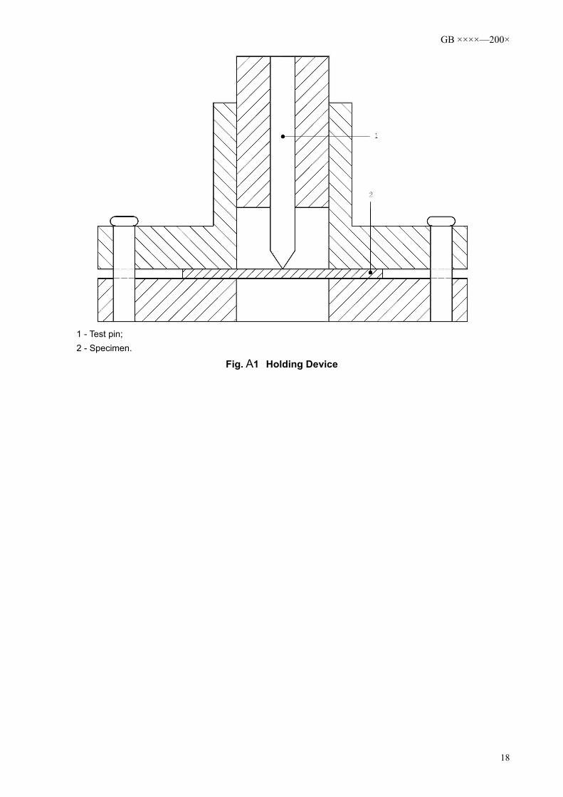
A.2.1.1.2 Holding deviceThe holding device is comprised of a jig which holds the specimen in an appropriate position and
guides the movement of the test pin (see Fig. A1). The test pin is installed in a solid metal cylinder of 00.005.08.24 +
− mm diameter and the specimen is clamped between 2 plates; a round opening of (25.00±0.05)mm diameter is provided on the plates. One of the plates is furnished with a cylindrical ring whose inner diameter is (25.00±0.05)mm; the cylinder glides inside the ring, enabling the tip of the test pin to point against the centre of the specimen.
A.2.1.2 ProceduresAs shown in Fig. A1, clamp the specimen between the plates then place the device into the testing
equipment. Start the equipment and allow the test pin to penetrate the specimen at a speed of (10±3)mm/min, and record the maximum force (in N) required to penetrate the penetration-resistant insert. The test pin should not penetrate the specimen by its entire length.
Tests shall be performed at 4 different points of the penetration-resistant insert; spacing between any 2 penetration points shall be at least 30mm.
A.2.1.3 Representation of ResultsThe minimum value out of the 4 tests of each insert is taken to be the test result of said Insert.
17
GB ××××—200×
1 - Test pin;2 - Specimen.
Fig. A1 Holding Device
18

GB ××××—200×
References
[1] prEN ISO 19952, Footwear — Vocabulary[2] EN ISO 20345: 2004 Personal protective equipment — Safety footwear[3] EN12568: 1998, Foot and leg protectors — Requirements and test methods for toecaps and
metal penetration resistant inserts[4] EN50321: 2000, Electrically insulating footwear for working on low voltage installations
19