Embed Size (px)
Citation preview
ICS25.120.30 J61
National Standard of PRC GB ××××—××××
Safety Requirements for high pressure metal die casting
units (EN869:1998,MOD)
(Reports the draft for approval)
(This draft was completed in:
January 2004)
××××-××-××Issuance ××××-××-××Implementation
Issued by General Administration of Quality SupervisionInspection and Quarantine of PRC
Preface
Chapter 3 in this standard is for recommendation, the rest are for enforcement. The modification on thisstandard is based on Safety Requirements for High Pressure Metal Die Casting Units EN869:1998 (English version). This standard is a new draft based on Safety Requirements for High Pressure Metal Die Casting Units EN869:1998, which technically distinguishes itself from EN869:1998 in the following aspects:
— Editing modification based on the original standard; — Deleted the preface and introduction part of the International Standard; — Deleted the Sources of Standards which appear in the catalogue of Cited Normative Documentwhile fail to appear in the text, and added the Cited Normative Document which appear in the originaltext while fail to appear in the catalogue; — the tables in the chapter that describes the glossaries and definitions in the original standard in the form of clauses, are changed; — a title for 7.1 of the original standard added;
— Deleted Appendix A in the original standards which are notin line with the situation in China (Informative Appendices). Thisstandard is proposed by China Machinery Industry Federation, centralized under the management of National FoundryStandardization and Technology Committee (SAC/TC186), anddrafted together by Ningbo East Die Casting Co., Ltd and JinanFoundry & Metal forming Machinery Research Institute. The maindraftsmen for this standard include Zu Fengnian and Lu Jun. Thisstandard is framed for the first time.
Safety Requirements for high pressure metal die casting unit
1 Scope This standard specifies the safety requirement for high pressure metaldie casting unit. The standard applies to die-casting machine and its accessory equipment, such as feed, core puller and spraying equipment.The standard does not apply to low pressure die casting machine,gravity casting machine as well as lost wax casting machine.
2 Normative Documents Cited by this Standard The clauses in the following documents that were cited by this Standard became clauses of this Standard. For citeddocuments with a date, all their subsequent modifications or revisions do not apply to this Standard (Corrected contents are not included). However, parties having reached an agreement based on cited standards with a date areencouraged to study whether the latest versions of the cited documents with a date are applicable. For citeddocuments without a date, the latest versions apply to this Standard. GB 5226.1-2002 Safety of Machinery-Mechanical and Electrical Equipment-Part 1: General Technical
Specifications (IEC60204-1:2000,IDT) GB/T 8196 Safety of Machinery-Guard Devices- General requirements for the design and mechanism of fixed and movable guards GB 12265.1-1997 Safety of Machinery- Safety distances to prevent danger zones being reached by the upper limbs (eqv EN 294:1992) GB 12265.3 Safety of Machinery- Minimum gaps to avoid crushing of parts of the human body (eqv EN 349:1993) GB/T 15706.1-1995 Safety of machinery--Basic concept, general principles for design--Part 1: Basic terminology, methodology GB/T 15706.2-1995 Safety of Machinery-Basic concepts, general principles for design-Part 2: Technical principles and specifications GB/T 16855.1-1997 Safety related parts of control systems--Part 1: General principles for design (eqv prEN 954-1:1994) GB/T 19436.1-2004 Electrical safety of machinery -Electro-sensitive protective equipment—Part 1:General requirements and test. (IEC
61496-1:1997,IDT) EN574: 1997 Safety of machinery--Two-hand control devices—Design principles EN614 - 1 : 1995 Safety of machinery – part 1:terminology and principles EN1005-1:2001 Safety of machinery –Human physical performance -part 1: terminology and definitions EN1005-2:2003 Safety of machinery-Human physical performance-part 2: Manual management of project related with machinery EN1005-3:2002 Safety of machinery-Human physical performance-part 3: Force limit for machinery operation EN1265:2000 Test criterion for noise emitted by casting machine and equipment EN61310-1:1995 Safety of machinery-Principles for Indication, identification and movement-part 1: vision, hearing and sensor signal ISO7745:1993 Hydrodynamic-fire protection medium; principles for usage ISO/TR11688-1:1995 Acoustics-Recommended methods for designing machinery and equipment with low noise-part 1: plan
3 Glossaries and Definitions The following terminology and definitions are adopted by this standard
3.1 Basic Glossaries and Definitions The term “casting” means “die casting” in this standard. The definition for this term is as follows:
3.1.1
Die Casting The process of forcing molten metal into a die, and being kept under high pressure until it is completely curdled.
3.1.2
Die Casting Machine A dynamical machine that forces molten metal under high pressure into reusable dies, which are fixed on the fixed platen of the machine
3.1.3 Die Casting Unit Production unit formed by die casting and its ancillary equipment 3.1.4 Ancillary Equipment Auto devices of die casting machine in the process of production, such as metal feed/parts/spraying equipment for dies
3.1.5 Metal Materials for die casting
3.2 Terminology and definitions for machine type, components, machine parts, machine area, guarddevices and guard arrangement
3.2.1 Machine Type 3.2.1.1 hot-chamber die casting machine Die casting machine with its inject chamber and plunger immerged under the
surface of molten metal in the die casting furnace
3.2.1.2 cold- chamber die casting machine
Die casting machine with quantificational molten metal in the independent diecasting furnace being sent to the inject chamber
3.2.1.3 Horizontal cold- chamber die casting machine
Horizontal installed die casting machine in the injectchamber
3.2.1.3 Vertical cold- chamber die casting machine
Vertically installed die casting machinein the inject chamber Note: For differenttypes of die casting machine, please see picture1-picture 3
3.2.2 Components 3.2.2.1 Die closing system
Components for opening and closing the die, and helping the die to resist theforces upon the metal in the process of solidification
3.2.2.2 Injection system Component that presses metals into the die from inject chamber, and
press the metal in the process of solidification. 3.2.2.3 Ejector system
Devices that eject the die castfrom the dies cavity 3.2.2.4 Core puller
Devices for starting and controlling the movement of mandrel
3.2.2.5 automatic tie bar puller Automatic tie bar puller for setting process of the die
3.2.2.6 automatic ejector coupler
Devices that connect the liftout plate of the machine with the ejecting devices of the die automatically

Picture 1- Picture 3

3.2.2.7 automatic die clamper Devices that fix the die on the fixed platen
3.2.3 Machine Parts 3.2.3.1 fixed platen
3.2.3.2 moving platen
3.2.3.3 thrust platen
3.2.3.4 tie bar
3.2.3.5 injection drive
3.2.3. shot sleeve(cold-chamber die casting machine)
3.2.3.7 plunger
3.2.3.8 plunger rod
Rod that connects plunger and injection drive devices
3.2.3.9 counter plunger (horizontal cold-chamber die casting machine with vertical injection)
Plunger that closes down the sprue before die casting, and ejects the slug after the die casting
3.2.3.10 gooseneck (hot-chamber die casting machine) Injection system parts that ate immerged in the molten metal
( including injection chamber and metal passage) 。
3.2.3.11 nozzle Connecting fitting that is used to connect
goose neck and fixed half die 3.2.3.12 sprue
Connecting fitting between injection chambers (cold chamber die casting machine), or the one that is used to connect nozzle (hot-chamber die casting machine) and fixed half die. 3.2.3.13 slug
Platen with fixed semi-norm and injectionsystem
Platen with movable semi-norm
Platen with die closing mechanism andclosing cylinder
Round bar that carries combined load, anddirects moving platen
Power hydraulic system that moves and throw forcesupon the plunger
Cylindrical container which throws forces from theinner part upon the molten metal
Plunger that presses the metal into injection chamber, and throwforces upon the metal in the process of solidification
Metals that are solidified in the injection chamber and ejected with die cast 3.2.3.14
Ejector plate
3.2.3.15 ejector rod
3.2.4 Machine Area 3.2.4.1 Die area
3.2.4.2 Die closing mechanism area
3.2.4.3 Injection drive area
3.2.5 Guard devices/ guard measures 3.2.5.1 Fixed guard
3.2.5.2 Movable guard
For systems directly controlled by movable safety devices, the system is able to prevent the closing of thedie in case the control system meets trouble
3.2.5.5 Self monitoring control system Controlling system that having troubles with safety functions will not arise accidentally started controllingsystem. The system is able to discover the trouble and prevent another dangerous movement.
3.2.5.6 electro-sensitive protective device (ESPD) See GB/T 19436.1。
3.3 Operation type
Parts that pass the movement to the die ejector system
Parts that connect the ejector plate of themachine with the die ejector system
Areas between fixed platen andmoving platen
Areas between moving platen andthrust platen
Areas between fixed platen andinject cylinder
See 3.22.1 in GB/T 15706.1-1995 and 4.2.2.2 in GB/T 15706.2-1995
See 3.22.2 in GB/T 15706.1-1995 and 4.2.2.3 in GB/T 15706.2-1995
3.3.2 manual
Independent Procedure manually operated as per the predetermined order in the circulation of the machine. Anindependent procedure in the process of execution, such as to close the die casting circulation or to conduct die castingcirculation for inspection or fault –discovering ( only applicable for circular operation order with fixed process )
3.3.1
setting Manual Operation with discretionary process and order. An independent procedure in the process of execution, such as the replacement of a die (not necessarily abide by the operational circular order.
3.3.3
3.2.5.3
two hand control two hand control See EN574
3.2.5.4 closing safety device closing safety device
semi-automatic Each circulation starts manually, and the whole circulation is completed automatically. In order to produce die cast, at lease one of the procedure in the circulation process is completed by the operator outside the machine. 3.3.4
automatic To start the next circulation after the completion of the former circulation. In order to produce die cast in succession, any outside process is automatically conducted by ancillary equipment 4 Danger Classification
4.1 Summarize The dangerous area of die casting machine is the area that causes harm for human body. The harm is caused by
the following factors: movement danger ( like extrusion or cut ), radiation danger ( like thermal radiation, splash of the metals, splash of high pressure liquids), the affect of noise, gas, steam and electricity. 4.2 Machinery danger
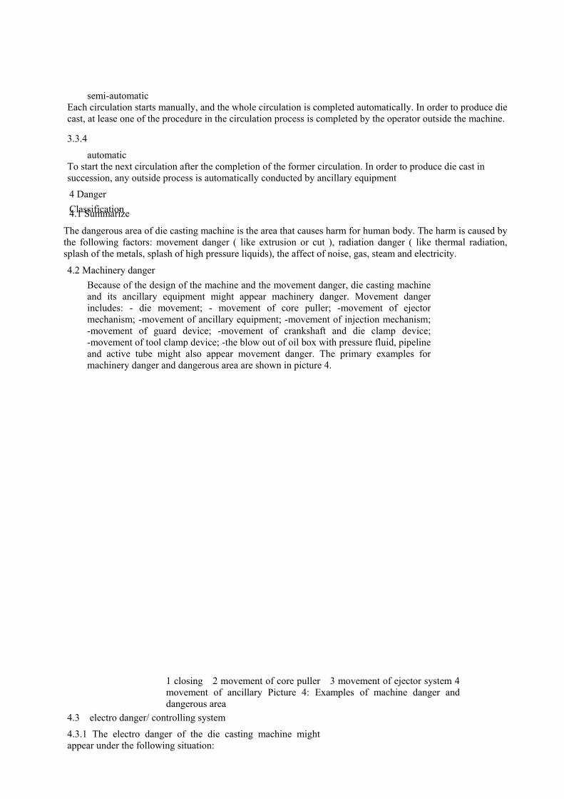
1 closing 2 movement of core puller 3 movement of ejector system 4movement of ancillary Picture 4: Examples of machine danger and dangerous area
Because of the design of the machine and the movement danger, die casting machineand its ancillary equipment might appear machinery danger. Movement dangerincludes: - die movement; - movement of core puller; -movement of ejector mechanism; -movement of ancillary equipment; -movement of injection mechanism; -movement of guard device; -movement of crankshaft and die clamp device;-movement of tool clamp device; -the blow out of oil box with pressure fluid, pipelineand active tube might also appear movement danger. The primary examples formachinery danger and dangerous area are shown in picture 4.
4.3 electro danger/ controlling system
4.3.1 The electro danger of the die casting machine mightappear under the following situation:
- electrical contact, direct or indirect; - external effect of electrical equipment; - harm caused by thermal radiation or other phenomenon ( such as spray of molten metal particles)
4.3.2 Unexpected movement of the machine caused by accident of the electro/ electronic control system, hydraulic pressure system, or pneumatically actuated system
4.5 fire danger Fire danger is derived from compound molten metal, heating unit, thermal surface and combustible material,
such as combustible lubricating grease, combustible hydraulic fluid, and combustible pressure mediumreleased when the pipeline is cracked. 4.6 Noise danger The noise danger for die casting machine
is derived from: - the die casting process; - the moving parts of the machine and their power source; -the installationmethod of the machine; - the process to spray the die
4.7 Dangers caused by gas, steam, fog and dust
The danger might happen under the following situation: - the usage of lubricant; - the bubble, steam, and fog released while some of the metals are melted and heat preserved, such as lead alloy; - the clear-up process
4.8 Factors that might harm the health of human beings Neglect the principles of man-machine engineering might harm the health of human beings.
4.8.1 Can not update overloading because of the design, such as: - in the debugging process for die casting machine; -the maintenance process of the die casting machine; -the manual fetching process of the die cast. 4.8.2 Repeatable moving work, such as :- manual feed for molten metal; - manual fetch 4.8.3 Unreasonable working gesture, like: - because of the unreasonable height of operation panel; -the wrong location of the operation panel; - Inconvenience for approach in the process of repair and debugging.
3)To fly out from between the mouth of the injector and the die ( see picture 7).–crack of the slug; - to contact with the heated structural member in the process ofmachinery operation; - to contact with the ancillary equipment of heating working media or tools; the release of heating working fluid; - the thermal radiation of smelter or pot.
2)To fly out from between the injection chamber and the injection plunger (see picture 5 and picture 6)
1)To fly off from the land of the die ( see picture 5, picture 6 and picture 7), or
Thermal danger that might be involved bydie casting machine includes: - the spray oroutflow of molten metal, such as:

1 land 2 places between injection chamber and plunger
Picture 5 dangerous area where the metal of horizontal
cold chamber die casting machine splashes

1 land 2 places between injection chamber and plunger
Picture 6 dangerous area where the metal of vertical
cold chamber die casting machine splashes

1 land 2 places between muzzle and die Picture 7 dangerous area where the metal of hot chamber die casting machine splashes
4.10 The danger to fall off from a high place Possible dangers that might happen when the operating crew are above the land or cellar
4.11 Special danger of cold chamber die casting machine 4.11.1 Crack of the slug
It is possible for slug without being well solidified to crack before it is pushed from the injection chamber. The primary dangerous areas for metals to splash are shown in picture 5 and picture 6
4.11.2 injection drive area
4.12 Special danger for vertical closing die casting machine For vertical closing die casting machine, danger might happen when the die slide off in the state of deadweight
4.13 Special danger for hot die casting machine 4.13.1 muzzle
It is possible for metals to splash if the muzzles are not well airproofed with the die 4.13.2 Unexpected starting in the process of die casting because of controlling accident If the die is open, the metal is shoot out when accident happens, thus cause the danger
of metal splashing. The primary dangerous area caused by metal splashing is shown in picture 7
5 Safety requirement and measures
In this chapter, we will try every means to recognize the relative danger. However, manufactures should ensure no additional dangers that are not covered in this chapter might happen according to their own risk evaluation. When additional risk does exist, GB/T15706.1 and GB/T15706.2 as well as the relevant standard A and standard B are recommended as a basis to deal with these extra risks. When additional devices are not part of the die casting machine, the designer, manufacturer as well as supplierof the die casting unit should consider their usage, and provide measures to ensure theses additional devices are safely connected with the die casting machine. Dangers that cannot be avoided by design, special safetydevice (such as guard device and lock control) and or special written procedure should be given to protect staffaround die casting machine.
Appropriate measures include: a) For places where a movable guard device is needed, the whole guard length of the distance between the guard device and the frame of the machine should not exceed 10mm, and the guard effect should be fulfilled by the structure of the guard device itself, or
b) The movable guard device and the ancillary guard device together form a guard area between the guard device and the frame structure of the machine to avoid the staff stay inside the guard device.
4.9 Debugging of die casting machine In the debugging process of the die casting machine, if the protecting devices are notallowed to function, additional danger might arise.
Danger might happen in the injection drive area between the injection chamber and plunger in the process of injection in vertical cold chamber die casting machine.
5.1 Brief introduction When design die casting machine, the various danger mentioned in chapter 4 and safety requirement and preventive measures mentioned in this chapter should be considered.
5.2 Machine Guard devices should be designed as per the rules specified in GB/T15706.1, GB/T15706.2 and GB/T 8196.Safety distance should be in accordance with rules specified in table 2 of GB12265.1-1997 and GB 12265.3. The design for safety devices itself should not cause harm. If the guard device is power driven, it should not cause clamp. When clamp happens, the power suppliedshould not be enough to cause harm, or an appropriate safety trigger mechanism is installed in front of theguard device to prevent harm. When starting safety trigger mechanism, movable guard device should bestopped or move in the counter direction. Safety trigger mechanism should be in accordance with therequirement described in classification 1 of GB/T 16855.1-1997.
5.2.1.1 Die area should be protected with movable guard devices, and being protected with ancillary fixed guard devices when necessary to avoid harms caused by movement (like the movement of die, core puller, and die spraying devices) (see picture 8). Ancillary devices should be provided when necessary to avoid staff staying between the guard device and the frame of the machine when the guard device is closed.
5.2.1 Guard devices for die area
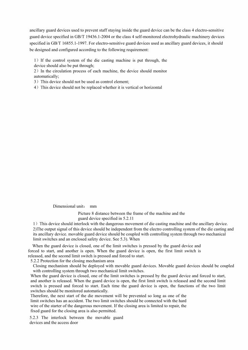
ancillary guard devices used to prevent staff staying inside the guard device can be the class 4 electro-sensitive guard device specified in GB/T 19436.1-2004 or the class 4 self-monitored electrohydraulic machinery devices specified in GB/T 16855.1-1997. For electro-sensitive guard devices used as ancillary guard devices, it should be designed and configured according to the following requirement:
1)If the control system of the die casting machine is put through, thedevice should also be put through; 2)In the circulation process of each machine, the device should monitor automatically; 3)This device should not be used as control element; 4)This device should not be replaced whether it is vertical or horizontal
Dimensional unit: mm
Picture 8 distance between the frame of the machine and the guard device specified in 5.2.11
1)This device should interlock with the dangerous movement of die casting machine and the ancillary device. 2)The output signal of this device should be independent from the electro controlling system of the die casting and its ancillary device. movable guard device should be coupled with controlling system through two mechanical limit switches and an enclosed safety device. See 5.3). When
When the guard device is closed, one of the limit switches is pressed by the guard device andforced to start, and another is open. When the guard device is open, the first limit switch isreleased, and the second limit switch is pressed and forced to start.
5.2.2 Protection for the closing mechanism area Closing mechanism should be deployed with movable guard devices. Movable guard devices should be coupled with controlling system through two mechanical limit switches.
When the guard device is closed, one of the limit switches is pressed by the guard device and forced to start, and another is released. When the guard device is open, the first limit switch is released and the second limit switch is pressed and forced to start. Each time the guard device is open, the functions of the two limit switches should be monitored automatically. Therefore, the next start of the die movement will be prevented so long as one of thelimit switches has an accident. The two limit switches should be connected with the hardwire of the starter of the dangerous movement. If the closing area is limited to repair, the fixed guard for the closing area is also permitted. 5.2.3 The interlock between the movable guarddevices and the access door

The movable guard devices and the access door should adopt the following method to interlock with the controlling system
5.2.3 The closing movement of the die and the setting movement of the core puller is allowed to start onlywhen the die area and the movable guard device and access door of the closing mechanism area are closed.
If the guard device in the die area is open, and the open movement of the moving platen is allowed, it is impossible to enter the extrusion area and the cut area behind the moving platen.
5.2.3.2 The movement of ejector is allowed to start only when the guard device of the closing mechanism area is closed. 5.2.3.3 The ejector and core puller are allowed to operate when they are under the following conditions:
2)Operation rules with a lock should be provided when choosing the switch, ( or adopt equivalent selection code under the numerical control ), so that to choose operation method when the guard devices is open under the situation of (1).
1)The ejector and core puller have no cut area or extrusion area; and
5.2.3.4 The opening of the guard device of the protection die should stop the movement of the die immediately.
5.2.3.5 Only when the movable guard device of the die or the access door is closed, and the die closing is heavily locked, can the injection begin.
Note: For crankshaft closing die casting machine, the closing is completed when the crankshaft is spread and the die isclosed and locked. For hydraulic closing die casting machine, the closing movement is not completely finished when the closing cylinder throws all the locking force. Additional measures should be taken to ensure the complete close down of thedie
5.2.3.6 The machine should not start by closing the guard device or the door. Additional starting switch independent from the limit switch of movable guard device should be installed. This clause is not applicablefor die casting machine whose vertical space between the tie bars do not exceed 650 mm. 5.2.4 die casting unit
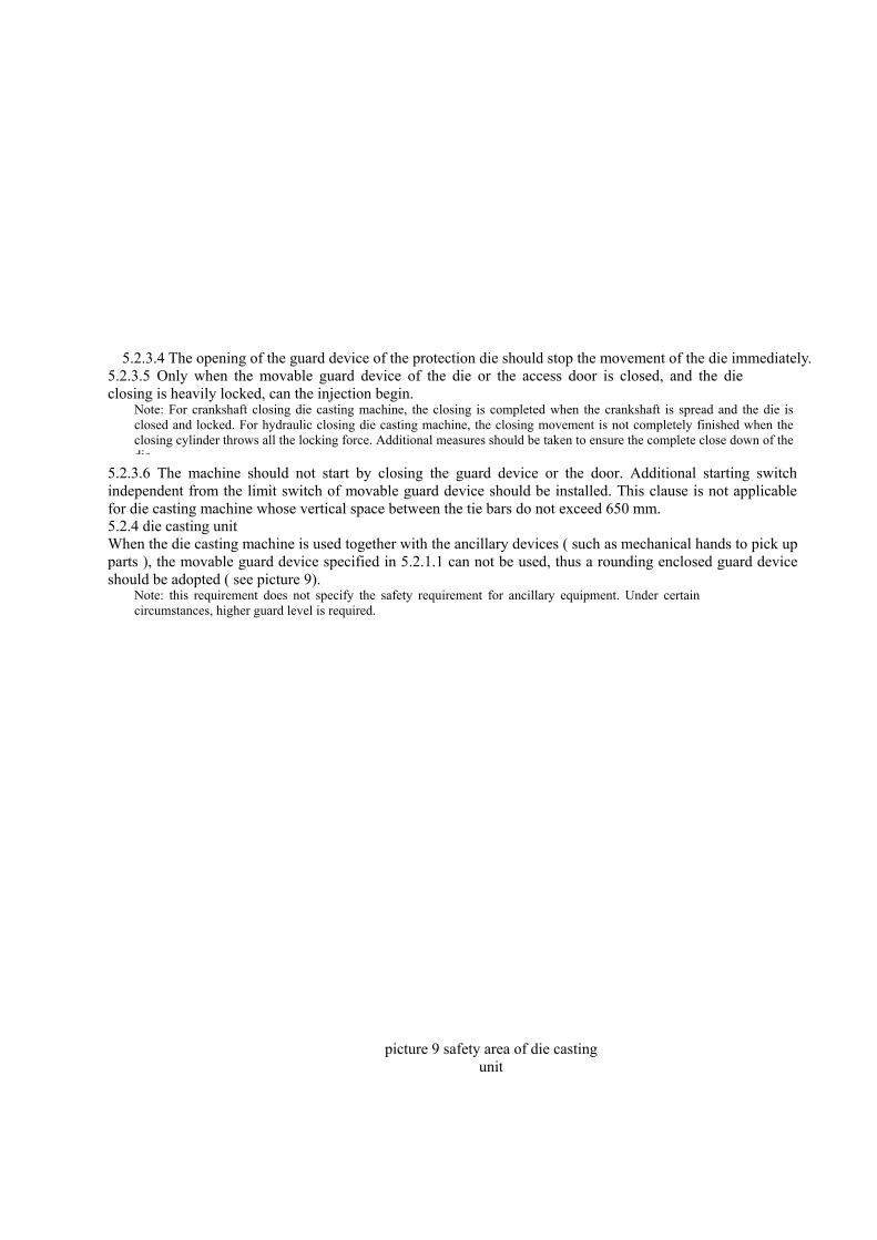
Note: this requirement does not specify the safety requirement for ancillary equipment. Under certaincircumstances, higher guard level is required.
When the die casting machine is used together with the ancillary devices ( such as mechanical hands to pick up parts ), the movable guard device specified in 5.2.1.1 can not be used, thus a rounding enclosed guard device should be adopted ( see picture 9).
picture 9 safety area of die casting unit
In the enclosed area, emergency stop devices should be installed in the appropriate places. The operation element of emergency stop devices should accommodate with the local situation, such as fixed operation element or movable element.
It is also used to prevent the die closing caused by the accident inthe controlling system. The examples of closing guard devices areas follows:
a) Ancillary hydraulic valve which is forced to start by the movable guard device or the access door.When the guard device is open, it will stop the pressure media to flow into closing cylinder, or the media to flow into the oil box (see picture 10); b) Pilot valve controlled to start by the movable guard device or the access door. It will control the valve in the power circuit to realize above (a) specified functions (see picture 11);
c) Ancillary electric limit switch controlled to start by the movable guard device or the access door. Itcontrols the ancillary hydraulic valve or pilot valve to realize the above (a) specified functions ( seepicture 12 and picture 13). From the safety point of view, the signal of limit switch should be independentfrom electric/ electronic controlling system when the electric limit switch drive valve is used.
5.3.3.1 The relevant safety of the controlling system with closing guard device specified in the following chapter is regarded as in accordance with the 4th class specified in GB/T 16855.1-1997. Closing guard device is an ancillary device in the power circuit, which is controlled and forced to start by the movable guard deviceor the access door in the die area.
5.3.3 The relevant safety of the controlling system of the dangerous movement with closing guard devices The parts of the controlling system of the die casting machine that affect the dangerous movement of the dieshould be in accordance with 4th class specified in GB/T 16855.1-1997, such as the movable guard devices and the access door in the die area.
5.3.2 The safety of controlling system related with the dangerous movement of die
The electric equipment of die casting machine should in accordance with the rules specified in GB5226.1, andthe stop function should in accordance with the 2nd class requirement specified in GB5226.1—2002.
5.3.1 Electric equipment 5.3 electric/controlling system
From a safety point of view, the signal of the limit switch should be independent from the die casting machine and theelectro controlling system of its ancillary equipment; the interlock of the limit switch should also independent fromthe die casting machine and the electric/electronic controlling system of its ancillary equipment.
The access door in the enclosed area should not be designed to open toward inside. The access door should be coupledwith the controlling system of the die casting machine and its ancillary device through two limit switches. When the door is closed, one of the limit switches is pressed by the door and forced to start, another limit switch is released. Theconnection method of the limit switch allows the start of the die casting machine and its ancillary equipment only when the door is closed and the order of the starting device (restarting device) is sent out. Restarting device should beinstalled next to the outdoor of the dangerous area, and is only allowed to start outside the enclosed area.
The monitor circuit should meet the following requirement; - the correct logic relationship of the signal of limit switch should be monitored; - the change of the location of the limit switch in each circulation of movable guard device should be monitored; - the counter signal of the guard device switch should be monitored; - the movement signal of the controlling circuit should function; - the monitor circuit should not produce controlling signal for hydraulic valve. If the safety monitoring of controlling system with closing guard device adopts electric system (like PLC), the signal of limit switch should connect with controlling system through independent input model.
The functions of limit switches in accordance with 5.2.1.1 and 5.3.3.1 should be monitored in each circulation of the machine or at least in each circulation process of the movable guard devices, so that it is able to identify automatically when any of the limit switch has an accident, thus prevent the start of the next circulation.
5.3.3.2 The function of the closing guard device and the action of the circulation of each machine, or at least in each circulation of the movable guard device, it is able to be self-monitored. This means, under the situation of hydraulic closing guard device, the position of the hydraulic valve should be monitored by the position switch. According to the position switch in 5.3.3.1 c), the ancillary hydraulic valve of the closing guard device controlled by the relay, the close of the relay should be monitored.
Electric system supply for limit switch: - the fiber of limit switch and the one of electric/ electronic controlling system should be separated; -should be connected with hardware, and functions on the ancillaryhydraulic valve directly; - direct directive contact function.

Examples of Safety related controlling system with closing guard device are shown in picture 10 –picture 13.
Picture 10 Examples of closing guard device with hydraulic valve that isforced to drive (see 5.3.3.1a)

Valve 2 is forced to operate with movable guard device. When the guard device is closed, it opens thepilot controlling non-return valve 3. Position switch S1 is responsible to monitor the dislocation ofvalve 2, while position switch S4 is responsible to monitor the relocation of monitor valve 3. Limit switch S2 and S3 monitor each other.
Picture 11 Closing guard device with pilot valve that is forced to drivepilot valve (see 5.3.3.1b)

Limit switch S4 (which is forced to operate by movable guard device ) is responsible to control valve 2. When the guard device is open, valve 2 disconnects the power resource in the closing cylinder. Thedislocation of valve 2 is monitored by position switch S1, while limit switch S2 and S3 monitor eachother. When the safety guard device is closed, the hydraulic power is open, and the dislocation of limitswitch S4 is monitored.
Picture 12 Examples of closing guard device with limit switch (its drive hydraulic valve) that is forcedto operate (see 5.3.3.1c)

Movable guard device is inspected by 3 limit switches: limit switch S1 controls valve 2, and valve 2controls the hydraulic resource of closing cylinder when valve 3 is disconnected. The dislocation of valve2 is monitored by location switch S5, while the dislocation of valve 3 is monitored by S4.
Picture 13 Examples of closing guard device with limit switch (its drive is closed first) that is forced tooperate (see 5.3.3.1c)
5.3.4 control of ancillary devices When the parts of controlling system of ancillary device affect the guard function, the design should make sure guard function operates when accident happens.
If the dangerous movement of the ancillary device is interlocked with its guard device (such as electric-sensitive device), the movement of ancillary device is permitted when the guard device is open. When the fetching device (from behind or top of the machine) or spaying device is in operation, the moveable guard device beside the operatoris permitted to open only when these devices leave the die area and can not be approached by operators.
5.4 Crack of molten metal Guard device and enclosed device in accordance with the requirement specified in 5.2.1 and 5.2.2 can prevent the harmcaused by the splash of metal. The temperature, speed and amount of the splashing metal should be taken into consideration.
5.5 combustible liquid 5.5.1 pressure fluid
The hydraulic system of die casting unit should use fire-resistant liquid (see ISO 7745), and the liquid used by hydraulic pipeline should be low burning, like water, glycol, etc. The design of the pipeline should be able to bear the anticipated mechanical load and heat load; the installation should be able to prevent accidental mechanical harm andheat harm. The hydraulic pipeline and joint should be applicable for low burning hydraulic liquid.
5.5.2 Spraying device being used to spray release agent If the release agent is combustible with pressure, measures should be taken when the pipelines arecracked to prevent the splash of liquid. Applicable measures are pump shut-off devices and pipeline crack safety device. If the device is injection-type, no additional measure is required. 5.5.3 heat exchanger media
In the process of the installation and close down for the joint and pipeline of heat exchanger, media should not be lighted up when there’s leak out.
5.6 noise
See ISO/TR 11688-1. Pay special attention to the following factors:-to choose low noise pump instead of enclose the pump; -consider to use muffler and waste gas filter for the release of pneumatically actuated energy; - to take special fasten measures to reduce the surging noise of pipeline; -to use reinforcing band or noise-reducing material to lighten the shake of thepanel and reduce the noise level; -to move the noise producing equipment farfrom people; - to enclose noise with acoustics or isolate noise with otherequipment.
5.7 gas, steam, fog and dust The harm produced from gas, stream, fog or dust is decided by the materials to be processed, which is beyond the controlling area of the designer, therefore, it is impossible to offer measures fro designers.
5.8 Factors that affect health The manual control for die casting machine operated semi-automatically should be designed following the principles of human-machine engineering. In the process of adjust and repair for the designed die casting machine, operator should have good gesture (see EN1005-1, EN1005-2, and EN1005-3).The installation of hoisting equipment, metal feed device and fetching device should be considered. The limit for manual exaltation should follow EN614-1 5.9 Safety measures for adjusting die casting machine, breaking device, fetching device, devices to tauten the tie bar and other ancillary devices. 5.9.1 adjustment without guard devices
(2) Using bimanual button specified in �B of EN574:1997, and the maximum closing speed is limited to 60 mm/s; or
(1) The maximum closing speed is limited to 30 mm/s, and the closing process should be conducted by pointing control device; or
When adjusting and following operation rules to adjust without guard device because of technical reasons, guarddevices that are in accordance with 5.2.1, 5.2.2, and 5.2.4 cannot be used. The connection of guard device andcontrolling system should follow the rules that locks are considered. Choose the switch and lock it in the positionof OFF, to make sure it cannot be started in the process of injection. The following requirement is also a must:

(3)When there’s no limit for speed, and the movement is started by the pointing control button, the inching of the moving platen is allowed, but the distance for each step should not exceed 5mm.
5.9.3 The twitching movement of the tie bar For the designed twitching device of the tie bar of the die casting machine, the prescribed speed for the tie bar to approach the calibrating plate in a distance of 300 mm should not exceed 30mm/s while adjusting. If the dangerous area is outside the safety distance following GB 12265.1, the speed can exceed this limit number. For pushing and twitching, they are only allowed to be conducted by pointing control device. 5.10 The location for a high place work
5.11.2 Movable guard device for injection area
5.11.3 the movement of the injection plunger
For cold die casting machine, the dangerous area of the metal feed device should be protected by independent guard device. The parts of the guard device that can be opened should be interlocked with control system.
The interlock should make sure: - when the guard device is open, the dangerous movement should be stopped; -only when the dangerous movement has completed, can the guard device be opened.
5.12 Additional protection measures for hot chamber die casting machine
5.12.1 Metal splash between the muzzle and the die
5.12.2 the start of the injection process At least two independent safety circuit elements are provided to make sure the injection process do
not happen when the controlling system has accident.
5.13 Additional safety protection measures for vertical closing move die casting machine
5.9.2 movement of core puller and ejector
When the operation rules choose to locate the switch on the setting position, the movement of core puller and ejector can only start according to pointing control device.
Appropriate working platform and ladder should be provided to prevent the fall off in the process of normal operation, setting and repair.
5.11.1 the crack of slug 5.11 Additional guard measure for cold chamber die casting machine
The crack of slug can be prevented by the following methods for designed cold chamber die casting machine.
b)For horizontal cold chamber die casting machine, the movable guard device in the die area should beconnected with the controlling system according to the following methods: - for machinery operated movable guard device, it is allowed to leave the enclosed place only when the die has finished 1/3 of its opening stroke.-For a manual operated movable guard device, the movable guard device is allowed to open through a stopdevice when the die stroke has exceeded at least 1/3 of its opening stroke.
a)Heavily locked control device can be used to make sure the enclosed time of the die has adjusted to be suitable for die casting process.
In vertical cold chamber die casting machine, the dangerous area between the injection chamber and the injection plungershould be protected by movable guard device. The connection method to connect it with the controlling system shouldmake sure that the movement of the injection plunger would only start when the guard device is locked down. Themovement of the injection plunger can also start when the guard device has arrived the enclosed position.
When the die of horizontal cold chamber die casting machine and the guard device are open, injection plunger is only allowed to enter die area by reducing its speed.
5.11.4 metal feed device
If the countercheck device remains its location, the connection for the locking and the control system should make sure the movement of the die will not be caused to start, and the state of the locking should be clear enough for identification.
It is possible to cause the movement of the die because of gravity. Therefore, the design for the controlling system should ensure the movement of the die is prevented because of the inefficiency of energy or the close of the control system. Hydraulic circuit (see picture 14) and machine countercheck device can be used to solve the problem. If the guard device is open, the designed machine countercheck device should be able to stop the movement of the die automatically. If the design and manufacture of the countercheck device is in accordance with the anticipated pressure scope of the machine, and the controlling system is designed and manufactured following 5.3.3, it should satisfy meet the requirement for closing guard device specified in 5.3.3.
At least one fixed guard device is used to prevent the metal splash between the muzzle and the die in the hot chamber die casting machine

Safety valve 4: safety guard device only used to prevent the peak pressure. It does not function under the pressure of normal operation, and relief when the pressure is 10% higher than the operation pressure. Safety valves being adjusted by manufactures should conduct type experiment and be pressurized.
Picture 14 The minimum requirement for the hydraulic control of the vertical closing move machine
6 safety requirement and inspection for measures
Safety requirement and measures can be inspected by eyeballing and the functional experiment of the equipment. The experiment for electric safety should follow GB5226.1, while the measurement of noise should follow EN1265 :2000
7 Usage information
The basic requirement of usage information has been listed in chapter 5 of GB/T15706.2-1995. Besides these basic requirements, the following items should be specially considered.
The following information should be labelled clearly and permanently on the die casting machine: - the name and address of the manufacture; -the designing serial number or model; -symbols of compulsory certification; -serial number/ machine number; - years of manufacture; -nominal rating locking force;-weight; -electric data; -ancillary electric equipment should be arranged with a permanent nameplate with data (including protection by enclosures, etc.)
Manufacturers should provide operating book for each machine (including all the ancillary equipment) specifying the characteristics of the die casting machine and special measures. The following examples describe the structure and content of the operating book.
a) Statement of the machine, especially: -manufacturer, the model of the machine, the equipment number, etc; -technical document (circuit diagram, list of components, data sheet, fittings information, etc); -anticipated usage, detailed information of additional/ matching machine and equipment interface; -forbidden usage (such as special materials forbidden by die casting, forbidden usage of special ancillary equipment); -following appendix A of GB/T15706.2-1995 and the detailed information of noise radiation measured by EN 126.
Using personal protection devices, such as, the protection of ear;- the description of ancillary equipment/system and its control connection (such as the effect of emergent stop/ safety device).
b) About the detailed information of transportation, setting, andinstallation, especially:-lifting instruction (such as sling and flying rings); - weight for transportation; -guard device for transportation and the remove of guard device before delivery;-the plant layout/ installation conditions ( design of groundsilland requirement of construction); -installation of the machine or single component/ instructions for assembly; -instructions for titling prevention and fall off from the high place;
c) detailed information about the delivery of usage and that can not be used:Especially-detailed information of power preparation (such as electricity and gas, hydraulic pressure, and pneumatically actuated); - detailed information of liquid media (such as low burning high pressure media); - detailed information of the assembly of special device(such as setting device); -about detailed information of start, operation and stop; -detailed information about the inspection for guard deviceand forbidden redo without authorization before delivery; - situations that the machine should stop to operate (management of the high pressure media , emptying instruction).
d) Instruction for operation, especially:
7.1 General Introduction
7.2 Least label
7.3 operating book
-About the detailed information of available safeguard devices -about daily inspection for safety guard devices;
-detailed information of special danger (such as special information for electricity and gas, hydraulic pressure, and settings, and re-delivery and usage after the setting); -if the metal to be dealt with produces harmful gas, bubble, dust and fog, information suggesting users to connect aerator with the machine should be provided;
1) -requirement for the qualification of the operator; 2) instructions on how to operate the machine for the operator;
3) Introduction fro the safe guard device and fault clearance when accident happens. – actions easy to cause accident, or abnormal operation; -instructions fro users to prevent danger, such as explosion caused by the reaction between molten metal and wet material; -instructions on how to fetch die cast with devices and how to use personal protection devices; - instructions on the remained danger, such as:
-Instructions on how to contact with special danger under special situation (such as repair, fault clearance)should be provided in the operation book, and labelled on the machine according to the characteristics of its danger (see EN61310-1). When no safe guard devices is required in the operation, available measures shouldbe specified following 5.9.1. - Instruction on the dangers caused by the following factors:
1) pressure that can not be lightened; 2) Wrong function of the PFK electrical
system; 3) Temperature; 4) Fire;
-description for the safety of the related control system; -operator;
1) vibration 2) radiation 3) The hot surface on the working area, the melting furnace area and the feeding area; 4) Environmental requirement for the Management and storage of hot die casting and the protectionfor human body; 4) the flying out of the remaining material
5) explosion atmosphere.- following the instructions of manual management specified in 5.8
The following instructions should be specially noticed: -as per the instructions after the redelivery specified in 7.3 c); -directions on preventive measures ( such as the exchange andlubrication of wearing parts, etc); -list of wearing parts; -instruction on the wrong information of controlling system andthe consequences; - failure reason and chart of measures forclearance; instructions that the system components should beclosed in the process of repair; - instructions on the remainedenergy when necessary and measures taken to reduce the energy.
7.4 service handbook Service book should include instructions of experiment, instructions of repair as well as protection measures for danger. Special qualification required by repair and suggestions, as well as the spare parts list, the reference chart and circuit diagram. The operation of guard device should have periodically inspection procedure. Times to be inspected should be specified according to the reliability of the device, the characteristics and the importance in the design phase, and modify in the operation phase.
�����������