Embed Size (px)
Citation preview
10\2414195_1 1
National Roads Telecommunications Services Project
Schedule 1.1a to NRTS Project Agreement
Schedule 1: Statement of Requirements
Schedule 1.1a: Transmission Service
Author Names Redacted under Sec 40 of the FOIA Exemptions ‘Personal Information’
Checker Names Redacted under Sec 40 of the FOIA Exemptions ‘Personal Information’
Approver Names Redacted under Sec 40 of the FOIA Exemptions ‘Personal Information’
GD00323/RT/E/481 Issue 1 Date: 8 September 2005

CONFORMED COPY

CONFORMED COPYNRTS Project
Schedule 1.1a: Transmission Service
GD00323/RT/E/481 Issue 1 Page i
List of Amendments
Issue No
Amendment Number
Date Clause Action
CONFORMED COPY NRTS Project
Schedule 1.1a: Transmission Service
GD00323/RT/E/481 Issue 1 Page ii
List of Contents
1 INTRODUCTION ...................................................................................................................... 1
1.1 [Not Used]................................................................................................................................. 1
1.2 [Not Used]................................................................................................................................. 1
1.3 [Not Used]................................................................................................................................. 1
1.4 [Not Used]................................................................................................................................. 1
1.5 [Not Used]................................................................................................................................. 1
1.6 Objectives of Transmission Service.......................................................................................... 1
1.7 Terminology.............................................................................................................................. 1
1.8 References to HA Documents .................................................................................................. 2
1.9 [Not Used]................................................................................................................................. 2
2 OVERVIEW OF TRANSMISSION SERVICE AND HIGH LEVEL REQUIREMENTS .............. 3
2.1 [Not Used]................................................................................................................................. 3
2.2 [Not Used]................................................................................................................................. 3
2.3 Definition of Scope of Transmission Service ............................................................................ 3
2.4 Service Categories ................................................................................................................... 3
2.5 [Not Used]................................................................................................................................. 7
2.6 [Not Used]................................................................................................................................. 7
2.7 [Not Used]................................................................................................................................. 7
3 TRANSMISSION SERVICE CATEGORY 1 – BESPOKE SIGNALLING AND MONITORING .......................................................................................................................... 9
3.1 [Not Used]................................................................................................................................. 9
3.2 [Not Used]................................................................................................................................. 9
3.3 Service Types in Category........................................................................................................ 9
3.4 Definition: Service Type 1A .................................................................................................... 10
3.5 Definition: Service Type 1B and Service Type 1C .................................................................. 13
3.6 Performance Requirements.................................................................................................... 14
3.7 Additional Requirements......................................................................................................... 14
3.8 [Not Used]............................................................................................................................... 14
CONFORMED COPY NRTS Project
Schedule 1.1a: Transmission Service
GD00323/RT/E/481 Issue 1 Page iii
4 TRANSMISSION SERVICE CATEGORY 2 – BESPOKE TRAFFIC DETECTION................ 17
4.1 [Not Used]............................................................................................................................... 17
4.2 Context ................................................................................................................................... 17
4.3 Service Types in Category...................................................................................................... 18
4.4 Definition: Service Type 2A .................................................................................................... 18
4.5 Definition: Service Type 2B .................................................................................................... 21
4.6 Definition: Service Type 2C .................................................................................................... 23
4.7 Performance Requirements.................................................................................................... 26
4.8 Additional Requirements......................................................................................................... 26
4.9 [Not Used]............................................................................................................................... 26
5 TRANSMISSION SERVICE CATEGORY 3 – BESPOKE TELEPHONES............................. 27
5.1 [Not Used]............................................................................................................................... 27
5.2 [Not Used]............................................................................................................................... 27
5.3 Service Types in Category...................................................................................................... 27
5.4 Definition: Service Type 3A .................................................................................................... 27
5.5 Performance Requirements.................................................................................................... 31
5.6 Additional Requirements......................................................................................................... 31
5.7 [Not Used]............................................................................................................................... 32
6 TRANSMISSION SERVICE CATEGORY 4 – BESPOKE CCTV ........................................... 33
6.1 [Not Used]............................................................................................................................... 33
6.2 [Not Used]............................................................................................................................... 33
6.3 Service Types in Category...................................................................................................... 33
6.4 Definition: Service Type 4A .................................................................................................... 34
6.5 Definition: Service Type 4B .................................................................................................... 37
6.6 Definition: Service Type 4C .................................................................................................... 41
6.7 Definition: Service Type 4D .................................................................................................... 41
6.8 Definition: Service Type 4E .................................................................................................... 42
6.9 Performance Requirements.................................................................................................... 42
6.10 Additional Requirements......................................................................................................... 45
6.11 Non-Standard Bespoke CCTV arrangements......................................................................... 46
6.12 Special Bespoke CCTV Related Services .............................................................................. 46
6.13 Impact of Regional Control Centres........................................................................................ 46

CONFORMED COPY NRTS Project
Schedule 1.1a: Transmission Service
GD00323/RT/E/481 Issue 1 Page iv
7 TRANSMISSION SERVICE CATEGORY 5 – GENERIC X.25............................................... 47
7.1 [Not Used]............................................................................................................................... 47
7.2 [Not Used]............................................................................................................................... 47
7.3 [Not Used]............................................................................................................................... 47
7.4 Introduction to Service Types ................................................................................................. 47
7.5 Definitions: National X.25 Network ......................................................................................... 48
7.6 Definitions: Service Type 5A................................................................................................... 48
7.7 Definitions: Service Type 5B................................................................................................... 48
7.8 Performance Requirements.................................................................................................... 50
7.9 Additional Requirements......................................................................................................... 51
7.10 [Not Used]............................................................................................................................... 52
8 TRANSMISSION SERVICE CATEGORY 6 – GENERIC POINT-TO-POINT ANALOGUE CIRCUITS ......................................................................................................... 53
8.1 [Not Used]............................................................................................................................... 53
8.2 Context ................................................................................................................................... 53
8.3 [Not Used]............................................................................................................................... 53
8.4 Definitions for Category 6 Service Types................................................................................ 53
8.5 Performance Requirements.................................................................................................... 54
8.6 Additional Requirements......................................................................................................... 54
9 TRANSMISSION SERVICE CATEGORY 7 – GENERIC PUBLIC TELECOMMUNICATION SERVICES .................................................................................... 56
9.1 [Not Used]............................................................................................................................... 56
9.2 [Not Used]............................................................................................................................... 56
9.3 [Not Used]............................................................................................................................... 56
9.4 [Not Used]............................................................................................................................... 56
9.5 Requirements ......................................................................................................................... 56

CONFORMED COPY NRTS Project
Schedule 1.1a: Transmission Service
GD00323/RT/E/481 Issue 1 Page v
10 TRANSMISSION SERVICE CATEGORY 8 – GENERIC IP SERVICE .................................. 59
10.1 [Not Used]............................................................................................................................... 59
10.2 [Not Used]............................................................................................................................... 59
10.3 Introduction to Service Types in Category 8 ........................................................................... 59
10.4 Definition of Terms.................................................................................................................. 61
10.5 Definition of Roadside-to-Centre Service Type: Service Type 8Rx......................................... 64
10.6 Definition of Centre-to-Centre Service Type: Service Type 8Cx............................................. 71
10.7 [Not Used]............................................................................................................................... 75
10.8 Performance Requirements.................................................................................................... 75
10.9 Additional Requirements......................................................................................................... 77
10.10 Supporting TCC to CO services.............................................................................................. 80
10.11 [Not Used]............................................................................................................................... 80
11 TRANSMISSION SERVICE CATEGORY 9 – GENERIC POINT-TO-POINT DATA CIRCUITS............................................................................................................................... 81
11.1 Introduction............................................................................................................................. 81
11.2 [Not Used]............................................................................................................................... 81
11.3 Introduction to Service Types in Category .............................................................................. 81
11.4 Definition of Service Types 9 CRx, 9RRx, 9CCx .................................................................... 85
11.5 Performance Requirements.................................................................................................... 85
11.6 [Not Used]............................................................................................................................... 85
11.7 [Not Used]............................................................................................................................... 85
12 TRANSMISSION SERVICE CATEGORY 10 – SWITCHED VIDEO SERVICES ................... 89
12.1 [Not Used]............................................................................................................................... 89
12.2 [Not Used]............................................................................................................................... 89
12.3 [Not Used]............................................................................................................................... 89
12.4 [Not Used]............................................................................................................................... 89
12.5 Introduction to Definitions ....................................................................................................... 89
12.6 Definition of Service Types ..................................................................................................... 92
12.7 Definition of Home Area, Community of Interest Area and Remote Area ............................... 92
12.8 Definition of Picture Quality Level ........................................................................................... 97
12.9 Definition: Video Format and Interfaces.................................................................................. 98
12.10 Definition of Service Control Interface .................................................................................. 100
12.11 Requirements: Service Control Interface .............................................................................. 101
CONFORMED COPY NRTS Project
Schedule 1.1a: Transmission Service
GD00323/RT/E/481 Issue 1 Page vi
12.12 Requirements: Switching ...................................................................................................... 103
12.13 Requirements: Picture Quality .............................................................................................. 103
12.14 Requirements: Traffic Handling Capability – General ........................................................... 104
12.15 [Not Used]............................................................................................................................. 104
12.16 [Not Used]............................................................................................................................. 104
12.17 [Not Used]............................................................................................................................. 104
12.18 [Not Used]............................................................................................................................. 104
12.19 [Not Used]............................................................................................................................. 104
12.20 [Not Used]............................................................................................................................. 104
12.21 Use of CCTV for Evidential Purposes................................................................................... 104
12.22 Performance Requirements.................................................................................................. 105
12.23 Video Recording ................................................................................................................... 107
13 TRANSMISSION SERVICE CATEGORY 11 – SWITCHED ERT ........................................ 113
13.1 Introduction........................................................................................................................... 113
13.2 [Not Used]............................................................................................................................. 113
13.3 [Not Used]............................................................................................................................. 113
13.4 Definition: Service Type 11A................................................................................................. 117
13.5 Performance Requirements.................................................................................................. 117
13.6 Aggregate Interface Requirements ....................................................................................... 119
13.7 Variant of Potential Interest to the HA................................................................................... 119
14 PERFORMANCE REQUIREMENTS FOR BESPOKE SERVICE TYPES ........................... 120
14.1 [Not Used]............................................................................................................................. 120
14.2 [Not Used]............................................................................................................................. 120
14.3 [Not Used]............................................................................................................................. 120
14.4 The Basic Performance Requirement................................................................................... 120
14.5 [Not Used]............................................................................................................................. 120
14.6 Additional Performance Requirements ................................................................................. 121
14.7 Testing Methodology ............................................................................................................ 121
14.8 [Not Used]............................................................................................................................. 122
14.9 Next Steps ............................................................................................................................ 122
14.10 [Not Used]............................................................................................................................. 123
CONFORMED COPY NRTS Project
Schedule 1.1a: Transmission Service
GD00323/RT/E/481 Issue 1 Page vii
15 GENERAL TRANSMISSION SERVICE REQUIREMENTS ................................................. 124
15.1 [Not Used]............................................................................................................................. 124
15.2 Scope of Supply.................................................................................................................... 124
15.3 Service Solution Specifications............................................................................................. 125
15.4 Critical Design Rules ............................................................................................................ 125
15.5 Permanent Test Network and Emulators .............................................................................. 126
15.6 Application Guidelines .......................................................................................................... 130
15.7 Service Delivery Points: Physical Locations ......................................................................... 130
15.8 Additional Service Delivery Points at Transmission Stations ................................................ 131
15.9 General Network Management Requirements...................................................................... 132
15.10 Fault Management................................................................................................................ 132
15.11 Performance Management ................................................................................................... 134
15.12 Security Management........................................................................................................... 137
15.13 Addressing and Location Service Requirements .................................................................. 138
15.14 Resilience and Restoration................................................................................................... 139
15.15 Resilience to Electricity Supply Outages .............................................................................. 144
15.16 Commercial Exploitation of Spare Network Capacity............................................................ 147
15.17 Use of the Coleshill Computer Centre .................................................................................. 148
16 SERVICE LEVEL REQUIREMENTS.................................................................................... 150
16.1 [Not Used]............................................................................................................................. 150
16.2 [Not Used]............................................................................................................................. 150
16.3 Outage.................................................................................................................................. 150
16.4 Outage Hours ....................................................................................................................... 150
16.5 HA Planned Outage State .................................................................................................... 152
16.6 Access Prevented State ....................................................................................................... 153
16.7 Defined Event Allowable Restoration Hours ......................................................................... 154
16.8 Defined Event Planned Permanent Repair ........................................................................... 155
16.9 Defined Electricity Supply Failure State and Defined EMI Waived Fault State ..................... 155
16.10 Attributable Outage Hours .................................................................................................... 156
16.11 Reporting Period................................................................................................................... 156
16.12 Reporting Zone..................................................................................................................... 156
16.13 Potential Operating Hours .................................................................................................... 157
16.14 Total Outage Hours .............................................................................................................. 157

CONFORMED COPY NRTS Project
Schedule 1.1a: Transmission Service
GD00323/RT/E/481 Issue 1 Page viii
16.15 Total Attributable Outage Hours ........................................................................................... 157
16.16 Availability............................................................................................................................. 157
16.17 Unadjusted Availability.......................................................................................................... 157
16.18 [Not Used]............................................................................................................................. 157
16.19 Reporting Requirements....................................................................................................... 158
16.20 [Not Used]............................................................................................................................. 158
17 HIGH LEVEL REQUIREMENTS PLACED ON THE BASE NETWORK.............................. 159
17.1 [Not Used]............................................................................................................................. 159
17.2 The concept of a Base Network............................................................................................ 159
17.3 Key features of SPC A capability .......................................................................................... 159
17.4 [Not Used]............................................................................................................................. 159
17.5 Capacity of the Base Network............................................................................................... 159
17.6 Requirements for build programme ...................................................................................... 161
17.7 Renewals.............................................................................................................................. 161
17.8 Regradings ........................................................................................................................... 161
17.9 Residual Life of Assets ......................................................................................................... 162
ANNEX A ..................................................................................................................................... 163
SUMMARY OF SERVICE DEFINITIONS ........................................................................................... 163
A.1 Summary of Service Definitions............................................................................................ 164
ANNEX B ..................................................................................................................................... 182
DEFINITIONS OF SERVICE DELIVERY POINTS AND INTERFACE TYPES ................................... 182
B.1 Definitions of Service Delivery Points ................................................................................... 183
B.2 Interface Type Definitions ..................................................................................................... 194
ANNEX C ..................................................................................................................................... 196
RULES FOR LOCATION OF ROADSIDE SDP FOR BESPOKE SERVICES..................................... 196
C.1 Rules for Physical Location of Roadside Service Delivery Points for Bespoke Service Types (Guidance Only) ....................................................................................................................... 197
ANNEX D ..................................................................................................................................... 199
PHYSICAL IMPLEMENTATION DIAGRAMS (ROADSIDE) ............................................................... 199
D.1 Key to Physical Implementation Diagrams ........................................................................... 200
D.2 Data Systems Overview – Service Type 1A ......................................................................... 201
D.3 Data Systems – Typical Buried Cable Implementation – Service Type 1A........................... 202
D.4 Data Systems – Typical Ducted Cable Implementation – Service Type 1A.......................... 203
CONFORMED COPY NRTS Project
Schedule 1.1a: Transmission Service
GD00323/RT/E/481 Issue 1 Page ix
D.5 MIDAS Overview (V26) – Service Type 2A .......................................................................... 204
D.6 MIDAS Overview – MIU / RS485 Data Transmission – Service Type 2B ............................. 205
D.7 MIDAS – Typical Buried Cable Implementation – Service Type 2A and 2B ......................... 206
D.8 Typical Ducted Cable Implementation – Service Type 2A and 2B........................................ 207
D.9 Emergency Roadside Telephone System Overview – Service Type 3A............................... 208
D.10 ERT – Typical Buried Cable Implementation Service Type 3A............................................. 209
D.11 ERT – Typical Ducted Cable Implementation – Service Type 3A......................................... 210
D.12 CCTV System Overview – Service Type 4 ........................................................................... 211
D.13 Typical Buried Cable Implementation (Shorrock) – Service Type 4A ................................... 212
D.14 Typical Ducted Cable Implementation (Shorrock) – Service Type 4A .................................. 213
D.15 Typical Buried Cable Implementation (Tyco) – Service Type 4B.......................................... 214
D.16 Typical Ducted Cable Implementation (Tyco) ....................................................................... 215
ANNEX E 216
[NOT USED] ..................................................................................................................................... 216
ANNEX F ..................................................................................................................................... 217
CRITICAL DESIGN RULES ................................................................................................................ 217
F.1 Critical Design Rules ............................................................................................................ 218
ANNEX G ..................................................................................................................................... 223
[NOT USED] ..................................................................................................................................... 223
ANNEX H ..................................................................................................................................... 225
TRANSMISSION SERVICE PROVISIONING CAPABILITIES............................................................ 225
H.1 Transmission Service Provisioning Capabilities.................................................................... 226
H.2 Designated Links .................................................................................................................. 230
H.3 Requirements for SPC and Enablement Rules..................................................................... 235
ANNEX I ..................................................................................................................................... 249
CAPACITY MODEL ............................................................................................................................ 249
I.1 Capacity Consumption of each Service Type ....................................................................... 250
I.2 Network Capacity Table........................................................................................................ 253
ANNEX J ..................................................................................................................................... 262
NON PTO DESIGNATED LINKS ........................................................................................................ 262
J.1 Non-PTO Designated Links .................................................................................................. 263
ANNEX K ..................................................................................................................................... 266

CONFORMED COPY NRTS Project
Schedule 1.1a: Transmission Service
GD00323/RT/E/481 Issue 1 Page x
METHODOLOGY FOR CONVERTING ST1B TO ST1A AS PART OF A PROGRAMME OF NMCS1 TO NMCS2 CONVERSION................................................................................................... 266
K.1 NMCS1 to NMCS2 Conversion............................................................................................. 267
ANNEX L ..................................................................................................................................... 276
NRTS NETWORK CAPACITY RESERVED FOR COMMERCIAL SERVICES................................... 276
L.1 Introduction........................................................................................................................... 277
ANNEX M ..................................................................................................................................... 279
OUTAGE TRIGGERS ......................................................................................................................... 279
M.1 Outage Triggers.................................................................................................................... 280
CONFORMED COPY NRTS Project
Schedule 1.1a: Transmission Service
GD00323/RT/E/481 Issue 1 Page xi
List of Figures Figure 1-1 [Not Used].............................................................................................................................. 2
Figure 3-1 Service Type 1A .................................................................................................................. 12
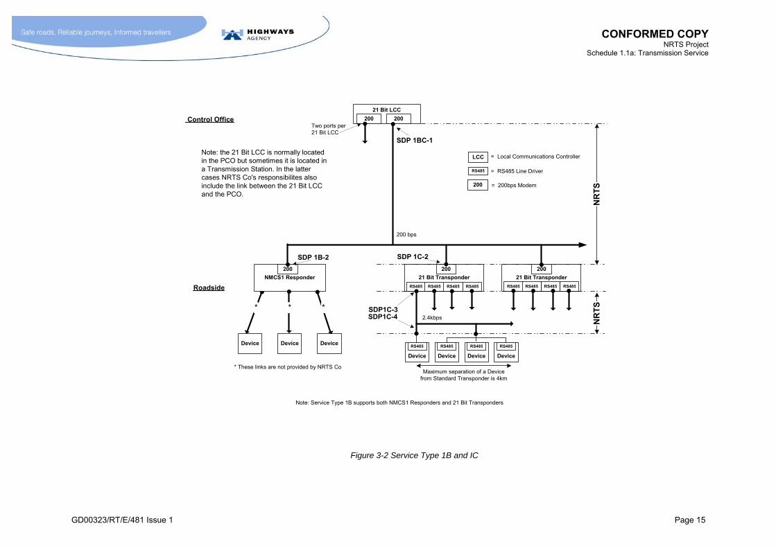
Figure 3-2 Service Type 1B and IC....................................................................................................... 15
Figure 4-1 Service Type 2A .................................................................................................................. 19
Figure 4-2 Service Type 2B .................................................................................................................. 22
Figure 4-3 Service Type 2C .................................................................................................................. 25
Figure 5-1 Service Type 3A .................................................................................................................. 29
Figure 6-1 Service Type 4A .................................................................................................................. 35
Figure 6-2 Service Type 4B .................................................................................................................. 39
Figure 6-3 Service Type 4C, 4D and 4E ............................................................................................... 43
Figure 7-1 Service Category 5 .............................................................................................................. 49
Figure 10-1 [Not Used].......................................................................................................................... 59
Figure 10-2 Reference Model for Definition of Access Line Bandwidth ................................................ 63
Figure 11-1 Service Category 9 ............................................................................................................ 83
Figure 12-1 Service Category 10 .......................................................................................................... 91
Figure 13-1 Service Category 11 ........................................................................................................ 115

CONFORMED COPY NRTS Project
Schedule 1.1a: Transmission Service
GD00323/RT/E/481 Issue 1 Page xii
List of Tables Table 2-1 Summary of Service Categories 1 to 4 (Bespoke) .................................................................. 4
Table 2-2 Summary of Service Categories 5 to 11 (Generic).................................................................. 5
Table 3-1 Functions of Various Service Types 1..................................................................................... 9
Table 4-1 [Not Used] ............................................................................................................................. 17
Table 4-2 Functions of Various Service Types 2................................................................................... 18
Table 5-1 [Not Used] ............................................................................................................................. 27
Table 5-2 Functions of Service Types 3A ............................................................................................. 27
Table 6-1 [Not Used] ............................................................................................................................. 33
Table 6-2 Summary of Service Types in Category 4............................................................................. 33
Table 7-1 Service Types and Associated Interface Types and Quantities for Category 5 .................... 47
Table 8-1 Definition of Service Types in Category 6 ............................................................................. 54
Table 8-2 Performance Requirements for Category 6 Service Types................................................... 55
Table 10-1 Service Category 8 Definitions for Centre-to-Roadside IP Service Types .......................... 69
Table 10-2 Service Category 8 Definitions for Centre-to-Centre IP Service Types............................... 73
Table 10-3 [Not Used] ........................................................................................................................... 75
Table 10-4 [Not Used] ........................................................................................................................... 75
Table 11-1 Service Types in Category 9 ............................................................................................... 81
Table 11-2 Service Category 9 Bandwidths and Interface Types ......................................................... 87
Table 12-1 [Not Used] ........................................................................................................................... 89
Table 12-2 [Not Used] ........................................................................................................................... 89
Table 12-3 Connectivity and Picture Quality Level Requirements for Service Types............................ 94
Table 12-4 Definition of Picture Quality Levels ..................................................................................... 95
Table 12-5 [Not Used] ......................................................................................................................... 104
Table 14-1 [Not Used] ......................................................................................................................... 120
Table 14-2 [Not Used] ......................................................................................................................... 120
Table 15-1 Emulator Requirements for each Service Category .......................................................... 129
Table 15-2 Service Restoration Times for Diverse Routing ................................................................ 143
Table 15-3 Electrical Resilience Requirements................................................................................... 146
Table 16-1 Defined Event Allowable Restoration Time....................................................................... 154
Table H.3-1 Enablement Rules ........................................................................................................... 246

CONFORMED COPY NRTS Project
Schedule 1.1a: Transmission Service
GD00323/RT/E/481 Issue 1 Page xiii
Table H.3-2 Requirements for Service Category 11 G and Type 600 Cabinet Enablement................ 247
Table H.3-3 The rate of consumption of storage for each PQL in Megabytes per camera per hour of recording...................................................................................................................... 248
Table I.1-1 Capacity Consumption of each Service Type ................................................................... 252
Table M.1-1 Outage Triggers .............................................................................................................. 288
CONFORMED COPY NRTS Project
Schedule 1.1a: Transmission Service
GD00323/RT/E/481 Issue 1 Page 1
1 INTRODUCTION
1.1 [Not Used]
1.2 [Not Used]
1.3 [Not Used]
1.4 [Not Used]
1.5 [Not Used]
1.6 Objectives of Transmission Service
1.6.1 M NRTS Co shall establish, operate and maintain a telecommunications service over the Project Road Network and Sites providing the required standard of services between such Service Delivery Points as may be required by the HA over the duration of the NRTS Contract. This shall include:
operation and maintenance of current and future transmission services;
programmed extensions of current transmission services;
introduction and extension of future transmission services;
reconfigurations of the service e.g. moving the links to signals to accommodate a road junction layout change;
switching on and off existing services (e.g. switching off roadside telephones during carriageway re-surfacing work);
removing redundant services.
1.7 Terminology
1.7.1 [Not Used]
1.7.2 M A Service Type shall be defined as a telecommunications service with defined transmission characteristics and associated performance requirements.
1.7.3 [Not Used]
1.7.4 M A Service Type Instance (STI) shall be defined as one implemented example of a Service Type.
1.7.5 M A Service Delivery Point (SDP) shall be defined as the logical and physical location of the interface between the Service Type Instance and the HA’s end device, application or system. For some Service Types, where a series of links is involved, several pairs of SDPs are required.
1.7.6 M Downstream Service Delivery Point (Downstream SDP) means the Service Delivery Point of a Service Type Instance that is the furthest away from the Control Office (or other SPC D location), at roadside or other locations that are not SPC D locations.
1.7.7 M Upstream Service Delivery Point (Upstream SDP) means the Service Delivery Point that is located at a Control Office or other SPC D location.

CONFORMED COPY NRTS Project
Schedule 1.1a: Transmission Service
GD00323/RT/E/481 Issue 1 Page 2
Figure 1-1 [Not Used]
1.7.8 [Not Used]
1.7.9 M An Interface Type shall be defined as the specification of the physical and electrical characteristics of a Service Delivery Point. For some Service Types, there is a range of Interface Types that may be selected for particular Service Delivery Points.
1.7.10 M A Service Category shall be defined as a grouping of related Service Types.
1.7.11 [Not Used]
1.7.12 M The Bespoke Service Types shall be defined as those Service Types whose definition and characteristics are particular to the HA applications that they support. This includes all the Service Types in Service Categories 1, 2, 3 and 4.
1.7.13 [Not Used]
1.7.14 M Generic Service Types shall be defined as those Service Types whose definition and characteristics are not intended to be particular to the HA. This includes all the Service Types in Service Categories 5 to 11.
1.7.15 [Not Used]
1.7.16 M A Control Office (CO) shall be defined as being either a Police Control Office (PCO) or a Regional Control Centre (RCC).
1.8 References to HA Documents
1.8.1 [Not Used]
1.8.2 M The HA issue controlled documents such as TR2066, MCG1058, MCH1617 where the issue version is indicated (typically by a letter). NRTS Co shall interpret any reference to an HA document contained in this Schedule as referring to the version of the document current at the Execution Date.
1.9 [Not Used]
CONFORMED COPY NRTS Project
Schedule 1.1a: Transmission Service
GD00323/RT/E/481 Issue 1 Page 3
2 OVERVIEW OF TRANSMISSION SERVICE AND HIGH LEVEL REQUIREMENTS
2.1 [Not Used]
2.2 [Not Used]
2.3 Definition of Scope of Transmission Service
2.3.1 [Not Used]
2.3.2 [Not Used]
2.3.3 [Not Used]
2.3.4 M NRTS Co shall make available to the HA Instances of any of the Service Types listed in this Schedule, as required by the HA, following the processes defined in the Processes document (Schedule 1.2).
2.4 Service Categories
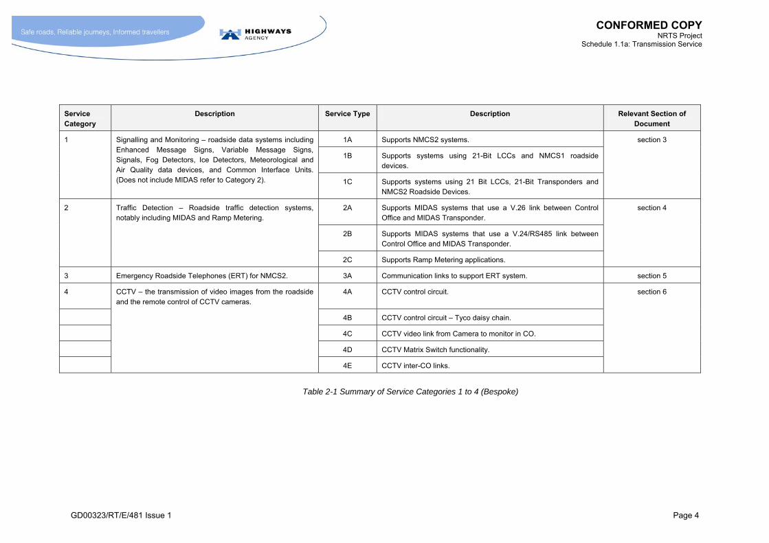
2.4.1 M The range of Service Categories and Service Types are summarised in Table 2-1 and Table 2-2. In cases where there is conflict between these summary descriptions and the definitions given in sections 3 to 13, the definitions in sections 3 to 13 shall take precedence.
2.4.2 [Not Used]
2.4.3 [Not Used]
2.4.4 M The formal definitions of the Service Types are summarised in Annex A.1.
CONFORMED COPY NRTS Project
Schedule 1.1a: Transmission Service
GD00323/RT/E/481 Issue 1 Page 4
Service Category
Description Service Type Description Relevant Section of Document
1A Supports NMCS2 systems.
1B Supports systems using 21-Bit LCCs and NMCS1 roadside devices.
1 Signalling and Monitoring – roadside data systems including Enhanced Message Signs, Variable Message Signs, Signals, Fog Detectors, Ice Detectors, Meteorological and Air Quality data devices, and Common Interface Units. (Does not include MIDAS refer to Category 2). 1C Supports systems using 21 Bit LCCs, 21-Bit Transponders and
NMCS2 Roadside Devices.
section 3
2A Supports MIDAS systems that use a V.26 link between Control Office and MIDAS Transponder.
2B Supports MIDAS systems that use a V.24/RS485 link between Control Office and MIDAS Transponder.
2 Traffic Detection – Roadside traffic detection systems, notably including MIDAS and Ramp Metering.
2C Supports Ramp Metering applications.
section 4
3 Emergency Roadside Telephones (ERT) for NMCS2. 3A Communication links to support ERT system. section 5
4 CCTV – the transmission of video images from the roadside and the remote control of CCTV cameras.
4A CCTV control circuit. section 6
4B CCTV control circuit – Tyco daisy chain.
4C CCTV video link from Camera to monitor in CO.
4D CCTV Matrix Switch functionality.
4E CCTV inter-CO links.
Table 2-1 Summary of Service Categories 1 to 4 (Bespoke)

CONFORMED COPY NRTS Project
Schedule 1.1a: Transmission Service
GD00323/RT/E/481 Issue 1 Page 5
Service Category
Description Service Type Description Relevant Section of Document
5 X.25 – The national X.25 network service for central logging and cross-boundary control.
Refer to Table 7-1
section 7
6 Analogue circuits to support various HA applications (e.g. an anemometer).
Refer to Table 8-1
section 8
7/PSTN Telephone connection (e.g. for ERT). section 9
7/GSM GSM connection (e.g. for ERT). section 9
7 Public Telecommunications Services for specialised applications e.g. ERT on All-Purpose Trunk Roads. Also includes GSM, ISDN and Packet Radio.
7/ISDN ISDN basic rate connection. section 9
8/R/x Refer to
Table 10-1
Roadside IP Services with Access Line Bandwidths between 1.2kbps to 100Mbps.
section 10 8 IP Service.
8/C/x Refer to
Table 10-2
Centre (e.g. Control Office) IP Services with Access Line Bandwidths between 33.6kbps and 100Mbps.
section 10
10 Switched Video Services. Future networked CCTV transmission links at defined picture quality levels with switching, and other network level requirements.
Refer to Table 12-3
Various CCTV Service Types for camera and monitor connections offering a range of Picture Quality Levels.
section 12
11 Switched Emergency Roadside Telephone – replacement service for the existing ERT service. (Includes traffic concentration.)
11A Service between Roadside and Control Office to support one ERT. section 13
Table 2-2 Summary of Service Categories 5 to 11 (Generic)


CONFORMED COPY NRTS Project
Schedule 1.1a: Transmission Service
GD00323/RT/E/481 Issue 1 Page 7
2.5 [Not Used]
2.6 [Not Used]
2.7 [Not Used]

CONFORMED COPY NRTS Project
Schedule 1.1a: Transmission Service
GD00323/RT/E/481 Issue 1 Page 9
3 TRANSMISSION SERVICE CATEGORY 1 – BESPOKE SIGNALLING AND MONITORING
3.1 [Not Used]
3.2 [Not Used]
3.3 Service Types in Category
3.3.1 M Section 3 of this Schedule defines the Service Types identified in Table 3-1.
Service Type Function HA units linked by Service Type
1A Support NMCS2 LCC Standard Transponder
Roadside Device(s) (NMCS 2)
1B Support NMCS1 21-Bit LCC (NMCS1)
Responder (NMCS1)
Not Applicable
1C Support NMCS1 systems that use NMCS2 Roadside Devices
21-Bit LCC (NMCS1)
21-Bit Transponder
Roadside Device(s) (NMCS2)
Table 3-1 Functions of Various Service Types 1
CONFORMED COPY NRTS Project
Schedule 1.1a: Transmission Service
GD00323/RT/E/481 Issue 1 Page 10
3.4 Definition: Service Type 1A
3.4.1 [Not Used]
3.4.2 M An Instance of Service Type 1A shall be defined as the supply, over the life of the Service Type Instance (STI), of both of the following links to a Service Delivery Point (SDP) that supports one or more Roadside Devices (see paragraph 3.4.4):
the link between:
SDP 1A-1 – the line side of the V.26 modem associated with a Local Communications Controller (LCC) at the Control Office; and,
SDP 1A-2 – the line side of the V.26 modem in a Standard Transponder;
and the link between:
SDP 1A-3 – the line side of an RS485 line driver in the Standard Transponder; and,
SDP 1A-4 – an SDP that supports connections to the line side of the RS485 line drivers of one or more Roadside Devices;
where:
the link between an Instance of SDP 1A-1 and the associated Instances of SDP 1A-2 shall have the transmission characteristics of a 4-wire multidrop circuit capable of supporting the ITU (International Telecommunications Union) V.26 standard with a data rate of 2.4kbps; and,
the link between an Instance of SDP 1A-3 and the associated Instances of SDP 1A-4 shall have the transmission characteristics of a 2-wire multidrop circuit capable of supporting the RS485 standard at a data rate of 2.4kbps;
and where:
the logical locations of SDPs are as shown in Figure 3-1;
the SDPs are as defined in Annex B.1.
3.4.3 M It shall be noted that it is often (but not necessarily) the case that several STIs will share a common physical infrastructure. Thus it is often the case that:
several STIs use the same pair of wires for the common sections of the link between SDP1A-3 and SDP1A-4; and,
several STIs use the same 4-wire circuit for the common sections of the link between SDP1A-1 and SDP1A-2.
This principle applies to other Service Types that use multidrop circuits, including Service Types 1B, 1C, 2A, 2B, 2C, 4A and 4B.

CONFORMED COPY NRTS Project
Schedule 1.1a: Transmission Service
GD00323/RT/E/481 Issue 1 Page 11
3.4.4 M The definition of the locations of SDPs shall be as given in Annex B.1. The definition of Service Type 1A is such that there is only one STI per Instance of SDP1A-4. For the avoidance of doubt, the consequence of these definitions for the location of SDP1A-4 is such that there is not a one-to-one relationship between the number of Roadside Devices and the number of STIs. The following cases are examples:
In the case of individual Matrix Signals (or Fog Detectors) at the side of the road, a single STI shall be required to support a single Matrix Signal (or Fog Detector).
In the case of a central reserve mounted back-to-back pair of Matrix Signals, the support of the pair of Matrix Signals shall only require a single STI, with the link between SDP1A-4 (located on the verge) and the pair of signals (located in the central reservation) being supplied by the HA.
In the case of gantry-mounted NMCS2 devices, all the gantry-mounted devices (including Matrix Signals and Enhanced Message Signs) require, in total, only one STI i.e. only one STI is required per gantry.
This principle applies to other Service Types where the definition of the location of the Roadside SDPs is such that there is not a one-to-one correspondence between the number of end devices and the number of STIs. Examples include Service Types 1B and 1C.

CONFORMED COPY NRTS Project
Schedule 1.1a: Transmission Service
GD00323/RT/E/481 Issue 1 Page 12
Figure 3-1 Service Type 1A
LCC
V.26 V.26V.26V.26
Device
RS485
Device
RS485
Device
RS485
Device
RS485
Standard Transponder
V.26
RS485RS485 RS485 RS485
Standard TransponderV.26
RS485RS485 RS485 RS485
SDP1A-2
Maximum separation of Device fromStandard Transponder is 4km
Control Office
Roadside
SDP1A-1
SDP1A-3SDP1A-4
Up to 4 portsper LCC
Up to 58 StandardTransponders per LCC Port
NR
TS
NR
TS
Up to 4 ports perStandard Transponder
Up to 30 devices perStandard Transponderport
V.26
RS485
= V.26 interface
= RS485 Line Driver
LCC = Local Communications Controller
2.4kbps
2.4kbps
CONFORMED COPY NRTS Project
Schedule 1.1a: Transmission Service
GD00323/RT/E/481 Issue 1 Page 13
3.5 Definition: Service Type 1B and Service Type 1C
Service Type 1B
3.5.1 M An Instance of Service Type 1B shall be defined as the supply, over the life of the Service Type Instance, of the following link to support one NMCS1 Responder:
the link between:
SDP 1BC-1 – the line side of the 200bps modem associated with the 21-Bit LCC; and
SDP 1B-2 – the line side of the 200bps modem associated with the NMCS1 Responder;
where:
the link between an Instance of SDP 1BC-1 and the associated Instances of SDP 1B-2 shall have the transmission characteristics of a 4-wire multidrop circuit capable of supporting NMCS1 signalling;
and where:
the logical locations of SDPs are as shown in Figure 3-2;
The SDPs are as defined in Annex B.1.
Service Type 1C
3.5.2 M An Instance of Service Type 1C shall be defined as the supply, over the life of the Service Type Instance, of both of the following links to support one Roadside Device:
the link between:
SDP 1BC-1 – the line side of the 200bps modem associated with the 21-Bit LCC;
SDP 1C-2 – the line side of the 200bps modem in the 21-Bit Transponder; and
the link between:
SDP 1C-3 – the line side of an RS485 line driver in the 21-Bit Transponder;
SDP 1C-4 – an SDP that supports connections to the line side of the RS485 line drivers of one or more Roadside Devices;
where:
the link between an Instance of SDP 1BC-1 and the associated Instances of SDP 1C-2 shall have the transmission characteristics of a 4-wire multidrop circuit capable of supporting NMCS1 signalling;
the link between an Instance of SDP 1C-3 and Instances of SDP 1C-4 shall have the transmission characteristics of a 2-wire multidrop circuit capable of supporting the RS485 standard at a data rate of 2.4kbps;
and where:
the logical locations of the SDPs are as shown in Figure 3-2;
the SDPs are as defined in Annex B.1.

CONFORMED COPY NRTS Project
Schedule 1.1a: Transmission Service
GD00323/RT/E/481 Issue 1 Page 14
3.5.3 M A consequence of the definitions of Service Types 1B and 1C is that multiple Instances of Service Type 1B and 1C can be supported on a common 4-wire multidrop circuit originating from the output of a single 200bps modem at the LCC.
3.6 Performance Requirements
3.6.1 M The Performance Requirements shall be as given in section 14.
3.7 Additional Requirements
3.7.1 [Not Used]
3.7.2 M Where the LCC is not located in the CO, NRTS Co shall regard the link between the LCC and the Control Office Based System (COBS) in the CO as forming part of the relevant Service Type. In other words, the supply of the Service Type shall include the supply of the LCC to CO link.
3.7.3 M Where the LCC is not located in the CO, a point-to-point link is currently employed with a V.24 (synchronous) interface operating at 9.6kbps. In some cases, this has been realised using V.29 modems. In other cases, a data circuit on a PDH system has been used. In both cases, NRTS Co shall be responsible for all the communications equipment that is between the V.24 interfaces at either end of the link. In other words, NRTS Co shall be responsible for the V.29 modems where these are deployed.
3.7.4 M NRTS Co’s obligation with respect to the V.29 modems referred to in paragraph 3.7.3 shall apply irrespective of the fact that these modems might be located on an equipment shelf that contains a mixture of HA and NRTS Co equipment.
3.7.5 M NRTS Co shall move any LCCs (and associated modem shelves) currently located in Transmission Stations (TS) to the relevant central facility (normally a CO) if requested to do so by the HA.
3.7.6 [Not Used]
3.7.7 [Not Used]
3.7.8 [Not Used]
3.7.9 [Not Used]
3.7.10 M NRTS Co shall convert any Stand Alone Controller (SAC) implementations, and other non-standard arrangements, to Service Type 1A in accordance with a programme agreed with the HA, in accordance with the Build Transmission Service process in Schedule 1.2 paragraph 8.7.15.1, without additional charge to the HA.
3.7.11 M When instructed by the HA, NRTS Co shall undertake programmes to convert Instances of Service Type 1B or 1C to a Service Type 1A using existing roadside infrastructure. The conversion of these Service Types is required to support HA programmes to replace NMCS1 roadside devices with NMCS2 roadside devices.
3.7.12 M NRTS Co shall take into account the need to co-ordinate such activities with those of the HA contractors involved in the replacement of roadside devices. A methodology for achieving this has been developed by the HA, and is described in Annex K.
3.8 [Not Used]
CONFORMED COPY NRTS Project
Schedule 1.1a: Transmission Service
GD00323/RT/E/481 Issue 1 Page 15
Figure 3-2 Service Type 1B and IC
NMCS1 Responder
200
21 Bit LCC
200 200
21 Bit Transponder
200
RS485RS485 RS485 RS485
21 Bit Transponder
200
RS485RS485 RS485 RS485
SDP 1C-2
Control Office
Roadside
SDP 1BC-1
Two ports per21 Bit LCC
NR
TS
NR
TS
RS485 = RS485 Line Driver
LCC = Local Communications Controller
200 bps
200 = 200bps Modem
Device Device Device
* * *
* These links are not provided by NRTS Co
Note: Service Type 1B supports both NMCS1 Responders and 21 Bit Transponders
SDP 1B-2
Note: the 21 Bit LCC is normally locatedin the PCO but sometimes it is located ina Transmission Station. In the lattercases NRTS Co's responsibilites alsoinclude the link between the 21 Bit LCCand the PCO.
SDP1C-32.4kbps
Device
RS485
Device
RS485
Device
RS485
Device
RS485
Maximum separation of a Devicefrom Standard Transponder is 4km
SDP1C-4

CONFORMED COPY NRTS Project
Schedule 1.1a: Transmission Service
GD00323/RT/E/481 Issue 1 Page 17
4 TRANSMISSION SERVICE CATEGORY 2 – BESPOKE TRAFFIC DETECTION
4.1 [Not Used]
Table 4-1 [Not Used]
4.2 Context
Service Type 2A and 2B
4.2.1 [Not Used]
4.2.2 [Not Used]
4.2.3 [Not Used]
4.2.4 [Not Used]
4.2.5 [Not Used]
4.2.6 [Not Used]
4.2.7 [Not Used]
4.2.8 [Not Used]
4.2.9 [Not Used]
4.2.10 [Not Used]
4.2.11 [Not Used]
4.2.12 [Not Used]
4.2.13 [Not Used]
4.2.14 [Not Used]
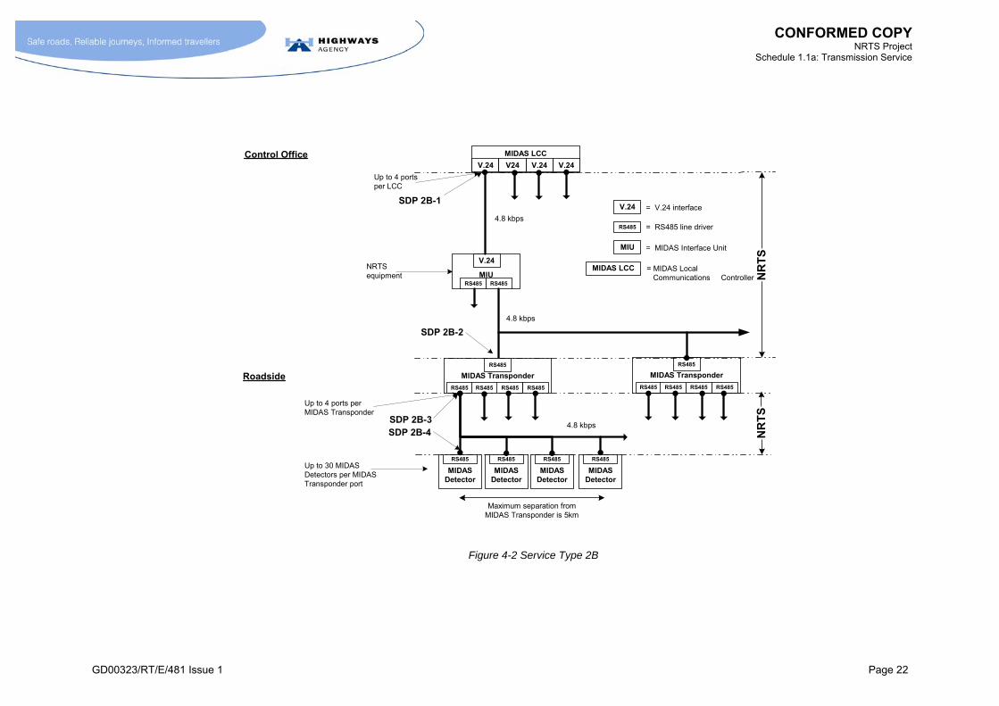
4.2.15 M Service Type 2B requires that conversion between V.24 and RS485 be performed. A unit known as a MIDAS Interface Unit is currently employed for this purpose. This is typically located in a Transmission Station. NRTS Co shall be responsible for this unit, or for providing the function performed by this unit by other means.
Service Type 2C
4.2.16 [Not Used]
4.2.17 [Not Used]
CONFORMED COPY NRTS Project
Schedule 1.1a: Transmission Service
GD00323/RT/E/481 Issue 1 Page 18
4.3 Service Types in Category
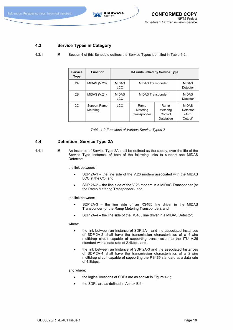
4.3.1 M Section 4 of this Schedule defines the Service Types identified in Table 4-2.
Service Type
Function HA units linked by Service Type
2A MIDAS (V.26) MIDAS LCC
MIDAS Transponder MIDAS Detector
2B MIDAS (V.24) MIDAS LCC
MIDAS Transponder MIDAS Detector
2C Support Ramp Metering
LCC Ramp Metering
Transponder
Ramp Metering Control
Outstation
MIDAS Detector
(Aux. Output)
Table 4-2 Functions of Various Service Types 2
4.4 Definition: Service Type 2A
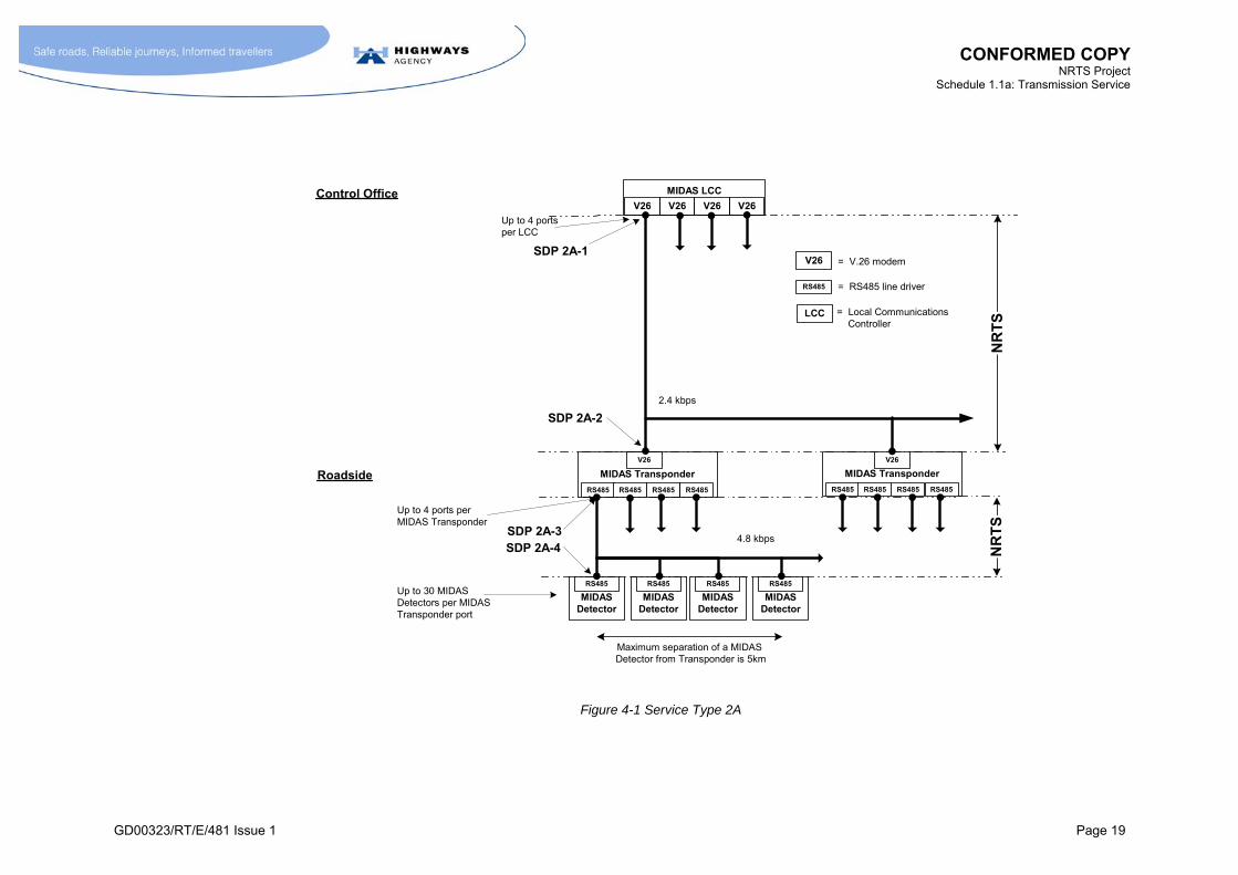
4.4.1 M An Instance of Service Type 2A shall be defined as the supply, over the life of the Service Type Instance, of both of the following links to support one MIDAS Detector:
the link between:
SDP 2A-1 – the line side of the V.26 modem associated with the MIDAS LCC at the CO; and
SDP 2A-2 – the line side of the V.26 modem in a MIDAS Transponder (or the Ramp Metering Transponder); and
the link between:
SDP 2A-3 – the line side of an RS485 line driver in the MIDAS Transponder (or the Ramp Metering Transponder); and
SDP 2A-4 – the line side of the RS485 line driver in a MIDAS Detector;
where:
the link between an Instance of SDP 2A-1 and the associated Instances of SDP 2A-2 shall have the transmission characteristics of a 4-wire multidrop circuit capable of supporting transmission to the ITU V.26 standard with a data rate of 2.4kbps; and,
the link between an Instance of SDP 2A-3 and the associated Instances of SDP 2A-4 shall have the transmission characteristics of a 2-wire multidrop circuit capable of supporting the RS485 standard at a data rate of 4.8kbps;
and where:
the logical locations of SDPs are as shown in Figure 4-1;
the SDPs are as defined in Annex B.1.
CONFORMED COPY NRTS Project
Schedule 1.1a: Transmission Service
GD00323/RT/E/481 Issue 1 Page 19
Control Office
NR
TSLCC = Local Communications
Controller
V26
RS485
= V.26 modem
= RS485 line driver
SDP 2A-1
Up to 4 portsper LCC
MIDAS LCC
V26 V26V26V26
MIDASDetector
RS485
MIDASDetector
RS485
MIDASDetector
RS485
MIDASDetector
RS485
MIDAS Transponder
V26
RS485RS485 RS485 RS485
MIDAS Transponder
V26
RS485RS485 RS485 RS485
SDP 2A-2
Maximum separation of a MIDAS Detector from Transponder is 5km
Roadside
NR
TS
Up to 4 ports perMIDAS Transponder
Up to 30 MIDASDetectors per MIDASTransponder port
SDP 2A-4SDP 2A-3
2.4 kbps
4.8 kbps
Figure 4-1 Service Type 2A


CONFORMED COPY NRTS Project
Schedule 1.1a: Transmission Service
GD00323/RT/E/481 Issue 1 Page 21
4.5 Definition: Service Type 2B
4.5.1 M An Instance of Service Type 2B shall be defined as the supply, over the life of the Service Type Instance, of both of the following links to support one MIDAS Detector:
the link between:
SDP 2B-1 – the V.24 output of the MIDAS LCC at the CO; and
SDP 2B-2 – the RS485 line driver at the MIDAS Transponder (or the Ramp Metering Transponder) for the link to the MIDAS LCC; and
the link between:
SDP 2B-3 – the line side of an RS485 line driver in the MIDAS Transponder (or the Ramp Metering Transponder); and
SDP 2B-4 – the line side of the RS485 line driver in a MIDAS Detector,
where:
the link between an Instance of SDP 2B-1 and 2B-2 shall be in accordance with the requirements specified in TR2146;
the link between an Instance of SDP 2B-3 and the associated Instances of SDP 2B-4 shall have the transmission characteristics of a 2-wire multidrop circuit capable of supporting the RS485 standard at a data rate of 4.8kbps;
and where:
the logical locations of SDPs are as shown in Figure 4-2;
the SDPs are as defined in Annex B.1.
CONFORMED COPY NRTS Project
Schedule 1.1a: Transmission Service
GD00323/RT/E/481 Issue 1 Page 22
MIU
V.24
RS485RS485
MIDAS LCC
V.24 V.24V.24V24Control Office
SDP 2B-1
Up to 4 portsper LCC
NR
TS
V.24
RS485
= V.24 interface
= RS485 line driver
MIU = MIDAS Interface Unit
NRTSequipment
MIDAS LCC = MIDAS Local Communications Controller
4.8 kbps
MIDASDetector
RS485
MIDASDetector
RS485
MIDASDetector
RS485
MIDASDetector
RS485
MIDAS Transponder
RS485
RS485RS485 RS485 RS485
MIDAS Transponder
RS485
RS485RS485 RS485 RS485
SDP 2B-2
Maximum separation fromMIDAS Transponder is 5km
Roadside
NR
TS
Up to 4 ports perMIDAS Transponder
Up to 30 MIDASDetectors per MIDASTransponder port
SDP 2B-4SDP 2B-3
4.8 kbps
4.8 kbps
Figure 4-2 Service Type 2B

CONFORMED COPY NRTS Project
Schedule 1.1a: Transmission Service
GD00323/RT/E/481 Issue 1 Page 23
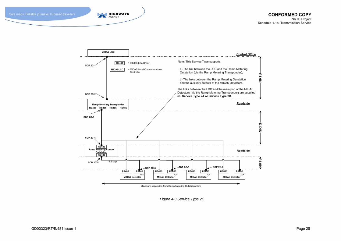
4.6 Definition: Service Type 2C
4.6.1 M An Instance of Service Type 2C shall be defined as the supply, over the life of the Service Type Instance, of all of the following links to support the auxiliary output of one MIDAS Detector:
the link between:
SDP 2C-1 – the MIDAS LCC at the CO;
SDP 2C-2 – the Ramp Metering Transponder; and
the link between:
SDP 2C-3 – the line side of an RS485 line driver in the Ramp Metering Transponder;
SDP 2C-4 – the line side of the RS485 line driver in a Ramp Metering Outstation (the port for the Ramp Metering Transponder); and
the link between:
SDP 2C-5 – the line side of the RS485 line driver in the Ramp Metering Outstation (the port for the auxiliary outputs of the MIDAS Detectors); and
SDP 2C-6 – the auxiliary output port of the MIDAS Detector;
where:
the link between SDP 2C-3 and the associated Instances of SDP 2C-4 shall have the transmission characteristics of a 2-wire multidrop circuit capable of supporting the RS485 standard at a data rate of 4.8kbps;
the link between SDP 2C-5 and the associated Instances of SDP 2C-6 shall have the transmission characteristics of a 2-wire multidrop circuit capable of supporting the RS485 standard at a data rate of 4.8kbps, as defined in TR2146;
and where:
the logical locations of SDPs are as shown in Figure 4-3;
the SDPs are as defined in Annex B.1.

CONFORMED COPY NRTS Project
Schedule 1.1a: Transmission Service
GD00323/RT/E/481 Issue 1 Page 25
MIDAS LCC
Ramp Metering Transponder
RS485 RS485 RS485 RS485
Ramp Metering ControlOutstation
RS485
MIDAS Detector
RS485 RS485
MIDAS Detector
RS485 RS485
MIDAS Detector
RS485 RS485
MIDAS Detector
RS485
RS485
SDP 2C-5 4.8 kbps
AUX AUX AUX AUX
SDP 2C-6 SDP 2C-6
Maximum separation from Ramp Metering Outstation 3km
a) The link between the LCC and the Ramp MeteringOutstation (via the Ramp Metering Transponder);
b) The links between the Ramp Metering Outstationand the auxiliary outputs of the MIDAS Detectors.
RS485
MIDASLCC
= RS485 Line Driver
= MIDAS Local Communications Controller
RS485
NR
TS
NR
TS
NR
TS
SDP 2C-1
SDP 2C-2
SDP 2C-3
SDP 2C-4
Control Office
Roadside
Roadside
Note: This Service Type supports:
The links between the LCC and the main port of the MIDASDetectors (via the Ramp Metering Transponder) are suppliedas Service Type 2A or Service Type 2B.
SDP 2C-6
Figure 4-3 Service Type 2C

CONFORMED COPY NRTS Project
Schedule 1.1a: Transmission Service
GD00323/RT/E/481 Issue 1 Page 26
4.7 Performance Requirements
4.7.1 M The Performance Requirements shall be as given in section 14.
4.8 Additional Requirements
Service Type 2B
4.8.1 [Not Used]
4.8.2 [Not Used]
4.8.3 [Not Used]
4.8.4 M In connection with Service Type 2B, NRTS Co shall ensure that any interfacing unit used for converting between V.24 and RS485 standards meets the requirements specified in TR2178.
Conversion Requirements
4.8.5 [Not Used]
4.8.6 [Not Used]
4.8.7 M Where the MIDAS LCC is not located in the CO, NRTS Co shall regard the link between the MIDAS LCC and the COBS system in the CO as forming part of the relevant Service Type. In other words, the supply of the Service Type shall include the supply of the MIDAS LCC to CO link.
4.8.8 M NRTS Co shall move any MIDAS LCCs (and associated modem shelves) currently located in Transmission Stations to the relevant central facility (normally a CO), if requested to do so by the HA, in accordance with the Build Transmission Service process in Schedule 1.2 paragraph 8.7.15.1.
4.8.9 [Not Used]
4.8.10 [Not Used]
4.8.11 [Not Used]
4.8.12 M NRTS Co shall convert defined Instances of Service Type 2A to Service Type 2B, without additional charge for the conversion exercise, according to a plan agreed with the HA in accordance with the Build Transmission Service process in Schedule 1.2 paragraph 8.7.15.1.
Non-MIDAS Traffic Detector Systems
4.8.13 [Not Used]
4.9 [Not Used]

CONFORMED COPY NRTS Project
Schedule 1.1a: Transmission Service
GD00323/RT/E/481 Issue 1 Page 27
5 TRANSMISSION SERVICE CATEGORY 3 – BESPOKE TELEPHONES
5.1 [Not Used]
Table 5-1 [Not Used]
5.2 [Not Used]
5.3 Service Types in Category
5.3.1 [Not Used]
5.3.2 M Section 5 of this Schedule defines the Service Types identified in Table 5-2.
Service Type
Function HA units linked by Service Type
3A Support ERT (NMCS2)
TLC Telephone Responder
ERT
Table 5-2 Functions of Service Types 3A
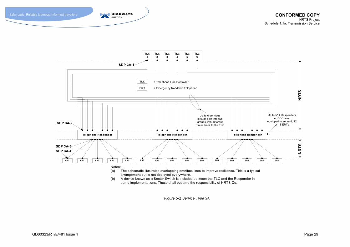
5.4 Definition: Service Type 3A
5.4.1 M An Instance of Service Type 3A shall be defined as the supply, over the life of the Service Type Instance, of both of the following links to support one ERT:
the link between:
SDP 3A-1 – the omnibus circuit side of the TLC; and
SDP 3A-2 – the omnibus circuit connection in the Telephone Responder,
and the link between:
SDP 3A-3 – the ERT connection in the Telephone Responder; and
SDP 3A-4 – the ERT;
where:
the link between an Instance of SDP 3A-1 and the associated Instances of SDP 3A-2 shall have the transmission characteristics of a 2-wire or 4-wire omnibus circuit capable of supporting an audio band signal (conveying both speech and signalling);
the link between an Instance of SDP 3A-3 and SDP 3A-4 shall have the transmission characteristics of a 2-wire telephone circuit (including the ability to support the appropriate signalling);
and where:
the logical locations of SDPs are as shown in Figure 5-1;
The SDPs are as defined in Annex B.1.

CONFORMED COPY NRTS Project
Schedule 1.1a: Transmission Service
GD00323/RT/E/481 Issue 1 Page 29
TLC1
TLC6
TLC5
TLC4
TLC3
TLC2
Telephone Responder
ERT ERTERTERTERT
Telephone Responder
ERT ERTERTERTERT
Telephone Responder
ERT ERTERTERTERT
SDP 3A-1
SDP 3A-2
SDP 3A-3
SDP 3A-4
Up to 6 omnibuscircuits split into twogroups with different
routes back to the TLC
Up to 511 Respondersper PCO, each
equipped to serve 6, 12or 18 ERTs
TLC
ERT
= Telephone Line Controller
= Emergency Roadside Telephone
NR
TS
NR
TS
Notes:(a) The schematic illustrates overlapping omnibus lines to improve resilience. This is a typical
arrangement but is not deployed everywhere.(b) A device known as a Sector Switch is included between the TLC and the Responder in
some implementations. These shall become the responsibility of NRTS Co.
Figure 5-1 Service Type 3A

CONFORMED COPY NRTS Project
Schedule 1.1a: Transmission Service
GD00323/RT/E/481 Issue 1 Page 31
5.5 Performance Requirements
5.5.1 M Performance Requirements shall be as defined in section 14.
5.5.2 M NRTS Co shall ensure that the circuit between SDP 3A-3 and SDP 3A-4 has the following electrical characteristics:
a maximum loop resistance of 600 ohms;
a maximum capacitance between conductors of 470nF;
as implied by the diagram shown in TR1330 section 5.1.1. This requirement shall hold provided the distance between SDP 3A-3 and SDP 3A-4 does not exceed 11km.
5.6 Additional Requirements
Support for signalling and data over audio path
5.6.1 [Not Used]
5.6.2 [Not Used]
5.6.3 [Not Used]
5.6.4 M NRTS Co shall ensure that the link between SDP 3A-1 and SDP 3A-2 shall be capable of supporting audio band signalling as defined by TR1329. NRTS Co shall ensure that any speech encoding employed as part of the delivery of this Service Type does not adversely affect the operation of such signalling.
5.6.5 M NRTS Co shall ensure that the links between SDP 3A-1 and SDP 3A-2 and between 3A-3 and 3A-4 shall be capable of supporting audio band data transmission as defined by MCF2350 Part B, for Type 354 ERT. NRTS Co shall ensure that any speech encoding employed as part of the delivery of this Service Type does not adversely affect the operation of such audio band data transmission.
5.6.6 [Not Used]
5.6.7 M NRTS Co shall ensure that the link between SDP 3A-3 and SDP 3A-4 shall be capable of supporting any signalling requirement associated with Type 352 and Type 354 ERTs (see MCE1242 and MCF 2350) and with the Telephone Responder (see TR1330).
Diverse Routing
5.6.8 [Not Used]
5.6.9 [Not Used]
5.6.10 M NRTS Co shall not reduce the degree of Diverse Routing (see paragraph 15.14.1) from that which is provided by the current arrangements. In particular the Blocking Probability under various failure modes of the communications links shall not be worse than that currently provided. (The Blocking Probability shall be defined as the proportion of call attempts made under specified load conditions that fail due to a shortage of system capacity.)
5.6.10.1 M NRTS Co shall ensure that the path between the Transmission Station and the CO uses Diverse Routing by the Transmission Full Service Start Date.

CONFORMED COPY NRTS Project
Schedule 1.1a: Transmission Service
GD00323/RT/E/481 Issue 1 Page 32
5.6.10.2 M Any new deployment involving the Provision of Instances of Service Type 3A over the entire span between two Transmission Stations shall adopt arrangements for Diverse Routing of the form shown in Figure 5-1. The circuits in the Longitudinal Cable shall be divided into two groups. One group shall be routed to the CO via one of the Transmission Stations associated with the section of longitudinal cable. The other group shall be routed to the CO via a different Transmission Station, located at the opposite end of the section of longitudinal cable. These arrangements shall be such that if the roadside cable or the link between a Transmission Station and the CO becomes severed, then communication is still possible between a Telephone Responder and the CO via the alternative path.
5.6.10.3 M The number of omnibus pairs deployed shall be subject to the SPC Rules, see Annex H.
Sector Switches
5.6.11 M NRTS Co shall be responsible for Sector Switches, where these are deployed in providing the link between the Telephone Responder and the TLC.
Converting from 2-wire to 4-wire operation
5.6.12 [Not Used]
5.6.13 [Not Used]
5.6.14 M Where Called Off, NRTS Co shall convert all TLC to Telephone Responder (i.e. SDP 3A-1 to SDP 3A-2) omnibus circuits from 2-wire to 4-wire operation, where cable capacity and Telephone Responder capability permits this. NRTS Co shall carry out this exercise in accordance with a programme acceptable to the HA.
5.6.15 [Not Used]
5.7 [Not Used]

CONFORMED COPY NRTS Project
Schedule 1.1a: Transmission Service
GD00323/RT/E/481 Issue 1 Page 33
6 TRANSMISSION SERVICE CATEGORY 4 – BESPOKE CCTV
6.1 [Not Used]
Table 6-1 [Not Used]
6.2 [Not Used]
6.3 Service Types in Category
6.3.1 [Not Used]
6.3.2 M Section 6 of this Schedule defines the Service Types identified in Table 6-2.
Service Type
Function HA units linked by Service Type
4A PTZ control information for camera (basic)
TV Controller in CO
CCTV Transponder at roadside
CCTV Outstation
4B PTZ control information for camera (daisy
chain)
TV Controller in CO
CCTV Transponder(s) at
roadside (daisy chained)
CCTV Outstation
4C Video path Output of Matrix Switch/input of
monitor
CCTV Outstation video output at
roadside
4D Matrix Switch control
functionality
Matrix Switch control interface
4E Link video image to other CO
Matrix Switch output in one
CO
Matrix Switch input in another CO
Table 6-2 Summary of Service Types in Category 4

CONFORMED COPY NRTS Project
Schedule 1.1a: Transmission Service
GD00323/RT/E/481 Issue 1 Page 34
6.4 Definition: Service Type 4A
6.4.1 M An Instance of Service Type 4A shall be defined as the supply, over the life of the Service Type Instance, of the following links to support one CCTV Outstation:
the link between:
SDP 4A-1 – the line side of the V.26 modem of the TV Controller (TVC) in the CO;
SDP 4A-2 – the line side of the V.26 modem in the TV Transponder (TVT);
and, (except where the TVT and CCTV Outstation are housed in the same cabinet) the link between:
SDP 4A-3 – the line side of the RS485 line driver in the TV Transponder (for the link to the CCTV Outstation);
SDP 4A-4 – the line side of the RS485 line driver in the CCTV Outstation;
where:
the link between an Instance of SDP 4A-1 and the associated Instances of SDP 4A-2 shall have the transmission characteristics of a 4-wire multidrop circuit capable of supporting the ITU V.26 standard with a data rate of 2.4kbps; and,
the link between an Instance of SDP 4A-3 and the associated Instances of SDP 4A-4 shall have the transmission characteristics of a 2-wire multidrop circuit capable of supporting the RS485 standard at a data rate of 4.8kbps;
and where:
the logical locations of SDPs are as shown in Figure 6-1;
the SDPs are as defined in Annex B.1.
6.4.2 [Not Used]
6.4.3 [Not Used]
6.4.4 [Not Used]
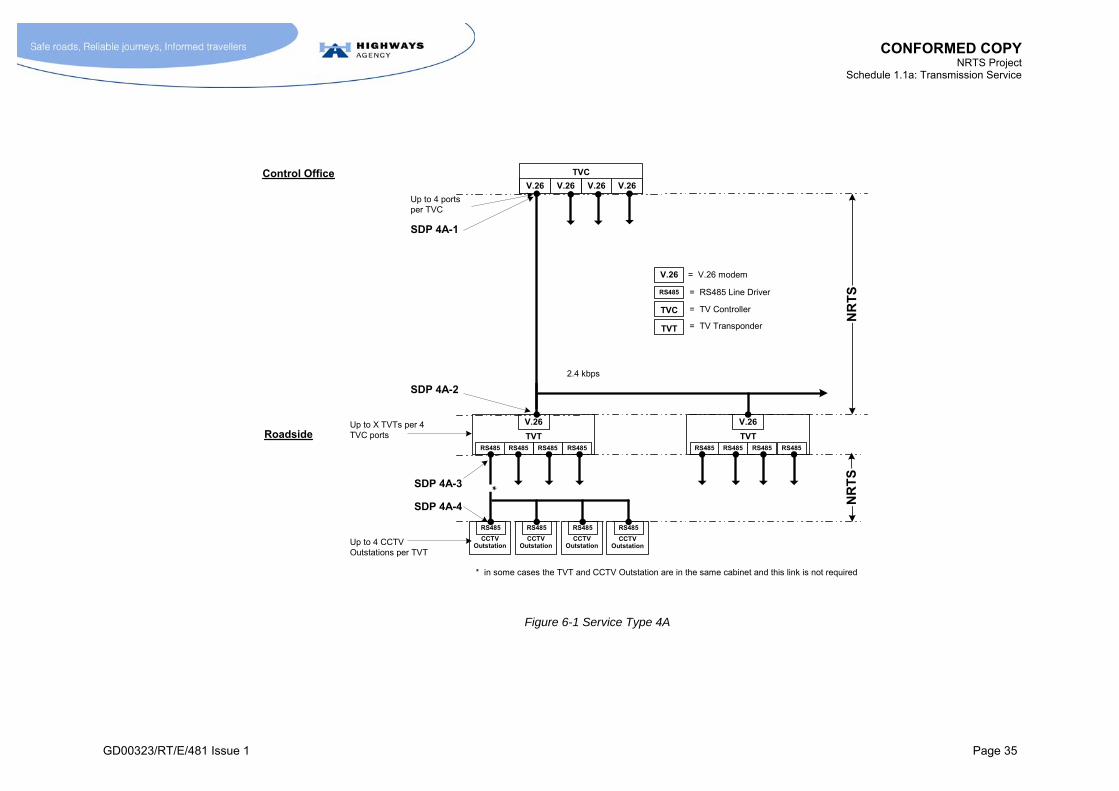
CONFORMED COPY NRTS Project
Schedule 1.1a: Transmission Service
GD00323/RT/E/481 Issue 1 Page 35
TVT
V.26
RS485RS485 RS485 RS485
TVT
V.26
RS485RS485 RS485 RS485
CCTVOutstation
RS485
CCTVOutstation
RS485
CCTVOutstation
RS485
TVC
V.26 V.26V.26V.26
SDP 4A-2
Control Office
Roadside
SDP 4A-1
Up to 4 portsper TVC
Up to X TVTs per 4TVC ports
NR
TS
NR
TS
Up to 4 CCTVOutstations per TVT
V.26
RS485
= V.26 modem
= RS485 Line Driver
TVC = TV Controller
SDP 4A-3
SDP 4A-4
CCTVOutstation
RS485
*
TVT = TV Transponder
* in some cases the TVT and CCTV Outstation are in the same cabinet and this link is not required
2.4 kbps
Figure 6-1 Service Type 4A


CONFORMED COPY NRTS Project
Schedule 1.1a: Transmission Service
GD00323/RT/E/481 Issue 1 Page 37
6.5 Definition: Service Type 4B
6.5.1 M An Instance of Service Type 4B shall be defined as the supply, over the life of the Service Type Instance, of the following links to support the supply of PTZ control information for one CCTV Outstation:
the link between:
SDP 4B-1 – the line side of the V.26 modem of the TV Controller in the CO; and,
SDP 4B-2 – the upstream side of the V.26 modem/amplifier/ equaliser in the first “Hermes” TV Transponder;
and, where required, the link(s) (refer to paragraph 6.5.2) between:
SDP 4B-3 – the downstream side of V.26 modem/amplifier /equaliser in “Hermes” TV Transponders; and,
SDP 4B-4 – the upstream side of the V.26 modem/amplifier /equaliser in the “Hermes” TV Transponders; and,
the link between:
SDP 4B-5 – the line side of the RS485 line driver in the “Hermes” TV Transponder; and,
SDP 4B-6 – the line side of the RS485 line driver in the CCTV Outstation;
where:
the link between an Instance of SDP 4B-1 and an Instance of SDP 4B-2 shall have the transmission characteristics of a 4-wire circuit; and,
the link between an Instance of SDP 4B-3 and an Instance of SDP 4B-4 shall have the transmission characteristics of a 4-wire circuit; and,
the link between an Instance of SDP 4B-5 and the associated Instances of SDP 4B-6 shall have the transmission characteristics of a 2-wire multidrop circuit capable of supporting the RS485 standard at a data rate of 4.8kbps;
and where:
the logical locations of SDPs are as shown in Figure 6-2;
the SDPs are as defined in Annex B.1.
6.5.2 M The definition of Service Type 4B is such that a single Instance of Service Type 4B might require zero, one or several occurrences of the link between SDP 4B-3 and SDP 4B-4, see Figure 6-2.


CONFORMED COPY NRTS Project
Schedule 1.1a: Transmission Service
GD00323/RT/E/481 Issue 1 Page 39
CCTV Hermes Transponder
RS485RS485 RS485
Up DownAmp/Eq
V.26
CCTV Hermes Transponder
RS485RS485 RS485
Up DownAmp/Eq
V.26
TVC
V.26 V.26V.26V.26
SDP 4B-2
Control Office
Roadside
SDP 4B-1
SDP 4B-3 SDP 4B-4
Up to 4 portsper TVC
Up to 62 CCTV Hermestransponders per 4 TVCports
NR
TS
NR
TS
Up to 3 ports perCCTV HermesTransponder
Up to 16 CCTVoutstations per 3 CCTVHermes Transponderports
V.26
RS485
= V.26 modem
= RS485 Line Driver
TVC = TV Controller
SDP 4B-3
SDP 4B-5
SDP 4B-6
Daisy chain link tofurther CCTV Hermestransponders
Amp/Eq = Line amplification and equalisation
CCTVOutstation
RS485
CCTVOutstation
RS485
CCTVOutstation
RS485
CCTVOutstation
RS485
CCTVOutstation
RS485
CCTVOutstation
RS485
Figure 6-2 Service Type 4B

CONFORMED COPY NRTS Project
Schedule 1.1a: Transmission Service
GD00323/RT/E/481 Issue 1 Page 41
6.6 Definition: Service Type 4C
6.6.1 M An Instance of Service Type 4C shall be defined as the supply, over the life of the Service Type Instance, of the following link to support the video output from one CCTV Camera. The link between:
SDP 4C-2 – the output side of the CCTV Camera (at the output of the character generator); and,
SDP 4C-1 – located at the output (i.e. monitor side) of the Matrix Switch at a patch panel in the equipment room at the CO;
where:
the logical locations of SDPs are as shown in Figure 6-3;
the SDPs are as defined in Annex B.1.
6.6.2 M The precise location of the SDPs in the CO shall be:
agreed with the HA before the Take-On of a Service Area for pre-existing STIs; and,
specified as part of the Provisioning process for new STIs.
6.7 Definition: Service Type 4D
6.7.1 M An Instance of Service Type 4D shall be defined as the provision of the functionality offered by a Matrix Switch and enabling all Instances of Service Type 4C in the CO area to be switched between monitor ports within a specific CO, where:
the overall functionality conforms to the requirements of MCE2015;
the switching TVC interface (SDP 4D-1) conforms to the requirements appropriate to the manufacturer of the equipment;
the video input ports on the Matrix Switch may be connected to CCTV Cameras located in the geographical area covered by the CO, or may be connected to video links to other COs (where such links are deployed i.e. Service Type 4E);
the video output ports from the Matrix Switch may be connected to monitors within the geographical area covered by the CO or may be connected to video links to other COs or the Traffic Control Centre (TCC) (where such links are deployed i.e. Service Type 4E).
6.7.1.1 M Where the capacity of a Matrix Switch for which NRTS Co has taken on responsibility is exhausted due to the Provisioning of additional Instances of Service Type 4C and a new Matrix Switch is required as a consequence, the supply of the new Matrix Switch, with functionality as described in paragraph 6.7.1, shall be executed as an Ad Hoc Project.
6.7.2 M The Service Delivery Point for control of the Matrix Switch(es) associated with a CO shall be defined as SDP 4D-1, where the logical location of this SDP is as shown in Figure 6-3 and the physical location of this SDP shall be as shown in Annex B.1.
6.7.3 [Not Used]
6.7.4 [Not Used]
6.7.5 [Not Used]
CONFORMED COPY NRTS Project
Schedule 1.1a: Transmission Service
GD00323/RT/E/481 Issue 1 Page 42
6.7.6 M The functionality that enables the control of the switching of cameras and monitors for a particular CO shall be regarded as a single Instance of Service Type 4D irrespective of whether the realisation of this functionality involves multiple switching elements. The implications of this requirement include the following:
in cases where a CO uses multiple matrix switches located at multiple locations, the total assemblage of equipment shall be treated as a single Instance of Service Type 4D;
in cases (such as the system in existence on the M25 in 2004) where hybrid arrangements involving a combination of matrix switch and Asynchronous Transfer Mode technology, the total assemblage of equipment required to support one CO shall be treated as a single Instance of Service Type 4D.
6.8 Definition: Service Type 4E
6.8.1 [Not Used]
6.8.2 M An Instance of Service Type 4E shall be defined as the provision of a link to support one video channel from SDP 4E-1 to SDP4E-2, where:
SDP 4E-1 – is the output port of a Matrix Switch in one CO; and,
SDP 4E-2 – is the input port of a Matrix Switch in another CO;
where:
the logical locations of SDPs are as shown in Figure 6-3;
the SDPs are as defined in Annex B.1.
6.8.3 [Not Used]
6.9 Performance Requirements
6.9.1 M The Performance Requirements shall be as given in section 14.

CONFORMED COPY NRTS Project
Schedule 1.1a: Transmission Service
GD00323/RT/E/481 Issue 1 Page 43
Figure 6-3 Service Type 4C, 4D and 4E
Matrix Switch(es) associatedwith CO 1
Matrix Switch(es)associated with CO 2
Mon MonMon TVC
Mon
TVC
GEN
Cam = CCTV camera
= character generator
= video monitor
= TV Controller
PCO
Roadside
SDP 4C-1
SDP 4C-2
SDP 4D-1
SDP 4E-1
SDP 4E-1
SDP 4E-2
TVC
SDP 4E-2
NR
TS
GEN
Cam
GEN
Cam
GEN
Cam
GEN
Cam
GEN
Cam
GEN
Cam
GEN
Cam
SDP 4D-1

CONFORMED COPY NRTS Project
Schedule 1.1a: Transmission Service
GD00323/RT/E/481 Issue 1 Page 45
6.10 Additional Requirements
General
6.10.1 M NRTS Co shall ensure that Service Type 4A, 4B, 4C and 4D deliver service in such a manner as to ensure that the HA equipment connected by these interfaces functions together correctly, in accordance with the requirements identified in MCE2015.
Service Type 4A and 4B
6.10.2 M NRTS Co shall, in relation to Service Types 4A and 4B, be responsible for any amplification and equalisation equipment associated with the transmission of PTZ control information. This includes:
amplification and equalisation equipment located in the Transmission Stations;
(where feasible) amplification and equalisation equipment located in HA supplied CCTV equipment..
6.10.2.1 M Subject to the agreement of the HA in each case, NRTS Co may implement Service Type 4B in an alternative arrangement in which:
the line equalisation within the TVT is switched off;
the amplification and line equalisation is performed within the TS by NRTS Co; and,
a topology is adopted by NRTS Co in which each TVT is directly connected to the TS via an omnibus 4-wire circuit, instead of the arrangement shown in Figure 6-2 in which TVTs are connected in a daisy chain.
6.10.3 [Not Used]
Functionality Upgrade
6.10.4 [Not Used]
6.10.5 [Not Used]
6.10.6 [Not Used]
6.10.7 [Not Used]
6.10.8 [Not Used]
6.10.9 [Not Used]
6.10.10 [Not Used]
6.10.11 [Not Used]
6.10.12 [Not Used]
CONFORMED COPY NRTS Project
Schedule 1.1a: Transmission Service
GD00323/RT/E/481 Issue 1 Page 46
6.11 Non-Standard Bespoke CCTV arrangements
6.11.1 [Not Used]
6.11.2 [Not Used]
6.11.3 [Not Used]
6.11.4 [Not Used]
6.11.5 M Where current arrangements differ from the service definitions given in sections 6.4 to 6.10, NRTS Co shall, for the purpose of pricing and the Service Credit Regime, regard the support of one camera requiring PTZ control as being equivalent to:
one Instances of Service Type 4A or Service Type 4B, depending on which definition most closely resembles the actual service provided, and;
one Instance of Service Type 4C.
6.11.6 M Where current CCTV systems offer additional functionality and capability, NRTS Co shall continue to provide this additional functionality and capability without additional charge.
6.11.7 [Not Used]
6.12 Special Bespoke CCTV Related Services
6.12.1 [Not Used]
6.12.2 M A Special Bespoke CCTV Related Service (SBCRS) shall be defined as a service associated with the existing CCTV systems that fulfils functions that are outside the functions performed by Service Type 4A, 4B, 4C, 4D and 4E. It includes:
systems to support video recording, where the equipment is located in Transmission Stations;
systems to provide CCTV related services to users in office locations other than the Control Office (e.g. to the offices of RMCs).
6.12.3 M NRTS Co shall continue to maintain all Special Bespoke CCTV Services. NRTS Co will be responsible for removing such Special Bespoke CCTV Services when they are no longer required. Any links associated with SBCRSs be shall regarded as Designated Links or Instances of Service Category 7 and shall not be included in the cost of SBCRs.
6.12.3.1 [Not Used]
6.12.4 [Not Used]
6.13 Impact of Regional Control Centres
6.13.1 [Not Used]
6.13.2 M The same pricing and Service Credit Regime for Service Category 4 Service Types shall apply irrespective of whether the CO is a PCO or an RCC.
6.13.3 [Not Used]
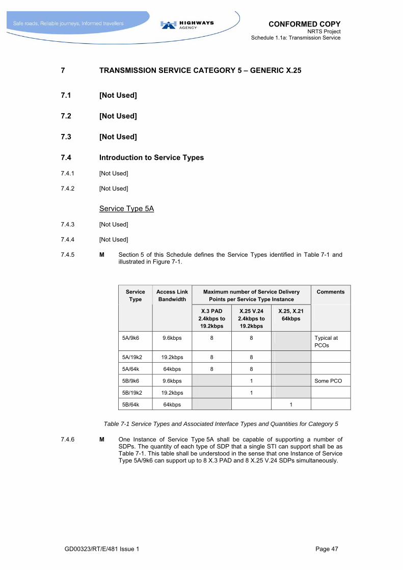
CONFORMED COPY NRTS Project
Schedule 1.1a: Transmission Service
GD00323/RT/E/481 Issue 1 Page 47
7 TRANSMISSION SERVICE CATEGORY 5 – GENERIC X.25
7.1 [Not Used]
7.2 [Not Used]
7.3 [Not Used]
7.4 Introduction to Service Types
7.4.1 [Not Used]
7.4.2 [Not Used]
Service Type 5A
7.4.3 [Not Used]
7.4.4 [Not Used]
7.4.5 M Section 5 of this Schedule defines the Service Types identified in Table 7-1 and illustrated in Figure 7-1.
Maximum number of Service Delivery Points per Service Type Instance
Comments Service Type
Access Link Bandwidth
X.3 PAD 2.4kbps to 19.2kbps
X.25 V.24 2.4kbps to 19.2kbps
X.25, X.21 64kbps
5A/9k6 9.6kbps 8 8 Typical at PCOs
5A/19k2 19.2kbps 8 8
5A/64k 64kbps 8 8
5B/9k6 9.6kbps 1 Some PCO
5B/19k2 19.2kbps 1
5B/64k 64kbps 1
Table 7-1 Service Types and Associated Interface Types and Quantities for Category 5
7.4.6 M One Instance of Service Type 5A shall be capable of supporting a number of SDPs. The quantity of each type of SDP that a single STI can support shall be as Table 7-1. This table shall be understood in the sense that one Instance of Service Type 5A/9k6 can support up to 8 X.3 PAD and 8 X.25 V.24 SDPs simultaneously.
CONFORMED COPY NRTS Project
Schedule 1.1a: Transmission Service
GD00323/RT/E/481 Issue 1 Page 48
Service Type 5B
7.4.7 [Not Used]
7.4.8 [Not Used]
7.4.9 [Not Used]
7.5 Definitions: National X.25 Network
7.5.1 M The National X.25 Network shall be interpreted as a national network linking all Instances of Service Types falling under Category 5, complying with ITU-T X.25 (1984) Recommendations.
7.6 Definitions: Service Type 5A
7.6.1 M An Instance of Service Type 5A/z (where z = 64k, 19k2 or 9k6) shall be defined as:
the provision of an access line with a bandwidth as indicated in Table 7-1 that links the X.25 trunk network to a local distribution node at a CO or other SPC D location;
the provision of such a local distribution node that enables this bandwidth to be shared by:
up to 8 ports that provide an X.25, V.24 DTE or DCE interface each with an interface speed of 2.4kbps to 19.2kbps, together with;
up to 8 ports that provide X.3 functionality with a V.24 interface with a speed of 2.4-19.2kbps.
the transport of data between these ports and other locations on the National X.25 Network.
7.7 Definitions: Service Type 5B
7.7.1 M An Instance of Service Type 5B/z (where z = 64k, 19k2 or 9k6) shall be defined as:
a) the provision of a single X.25 DCE port at a CO (or other SPC D location) providing access to the X.25 trunk network where the access link bandwidth and interface speed are as shown in Table 7-1;
b) the transport of data between this port and other locations on the National X.25 Network.
In relation to a), the option of an X.25 DTE port configuration shall also be available in those cases where the SDP is located at the site of a PSE.
7.7.2 [Not Used]
7.7.3 M NRTS Co shall develop an extended version of Annex B as part of the Service Solution Specification for Service Category 5. NRTS Co shall issue the Service Solution Specification for Service Category 5 as part of the Get Consent to Service Solution process.
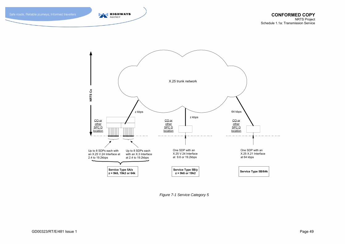
CONFORMED COPY NRTS Project
Schedule 1.1a: Transmission Service
GD00323/RT/E/481 Issue 1 Page 49
X.25 trunk network
z kbps
CO orother
SPC Dlocation
Up to 8 SDPs each withan X.25 V.24 Interface at2.4 to 19.2kbps
Up to 8 SDPs eachwith an X.3 Interfaceat 2.4 to 19.2kbps
Service Type 5A/xz = 9k6, 19k2 or 64k
z kbps
One SDP with anX.25 V.24 Interfaceat 9.6 or 19.2kbps
Service Type 5B/yz = 9k6 or 19k2
NR
TS
Co
64 kbps
One SDP with anX.25 X.21 Interfaceat 64 kbps
Service Type 5B/64k
CO orother
SPC Dlocation
CO orother
SPC Dlocation
Figure 7-1 Service Category 5

CONFORMED COPY NRTS Project
Schedule 1.1a: Transmission Service
GD00323/RT/E/481 Issue 1 Page 50
7.8 Performance Requirements
Introduction
7.8.1 [Not Used]
Performance Objectives
7.8.2 [Not Used]
7.8.3 [Not Used]
Possible Approaches with Current Network Management System
7.8.4 [Not Used]
7.8.5 [Not Used]
Working Assumptions
7.8.6 [Not Used]
7.8.7 [Not Used]
Link Availability
7.8.8 M NRTS Co shall operate a network management system that has the capability to detect when any of the network links (both access and trunk links) supporting the delivery of Category 5 Service Types are not available. The functionality supported by this system shall be limited to the functionality that the pre-existing X.25 network management arrangements have the capability to support.
7.8.9 M NRTS Co shall ensure that such faults are reported to the HA and remedial action undertaken in accordance with the Manage Faults process (Schedule 1.2 section 5.4).
7.8.10 [Not Used]
7.8.11 [Not Used]
7.8.12 M NRTS Co shall regard the Service Type Instance as not functioning correctly1 if any of the ports associated with the Service Type Instance are not functioning correctly, or if unused, would not function correctly if configured for use.
7.8.13 [Not Used]
1 In other words, NRTS Co shall regard the Service Type Instance to be in a state of Outage (see section 16) if any of the ports associated with the Service Type Instance are not functioning, or not functioning within specification.

CONFORMED COPY NRTS Project
Schedule 1.1a: Transmission Service
GD00323/RT/E/481 Issue 1 Page 51
Link Utilisation
7.8.14 M NRTS Co shall monitor the utilisation of each link (including trunk links and access links) continuously with a 15 minute sampling period. (i.e. 96 sample periods each of 15 minutes every 24 hours). This requirement is subject to the required functionality being supported without material change to the X.25 network management arrangements that existed prior to Take-On by NRTS Co.
7.8.15 M NRTS Co shall design and operate the National X.25 Network such that the link utilisation on any network link (other than the access links) does not exceed 50% for more than N of the sampling periods of 15 minutes in any Reporting Period of one month duration. (i.e. the utilisation shall exceed 50% for no more than N of the 2,880 15 minute sampling periods in a 30 day month). The number N shall be agreed as part of the Get Consent to Service Solution process and shall be based on the performance achieved in normal operation of the pre-existing arrangements.
7.8.16 [Not Used]
7.8.17 M NRTS Co shall ensure that the link utilisation attributable to network management traffic on any network link (including access links) does not exceed 10% for more than one sampling period of 15 minutes in any Reporting Period of one month duration. This requirement is subject to the required functionality to being supported without material change to the X.25 network management arrangements that existed prior to Take-On by NRTS Co.
7.9 Additional Requirements
7.9.1 M NRTS Co shall report all link (trunk link and access link) performance data on a monthly basis in tabular and graphical format together with reports showing how demand and utilisation trends are developing month by month. The report shall be in accordance with the Manage Contract process (Schedule 1.2 section 2.2).
7.9.2 M NRTS Co shall, in addition to the requirement stated in paragraph 7.8.15 offer the facility of more frequent, 5 minute, sampling periods for investigating cases of link congestion, i.e 288 sampling periods of 5 minutes in 24 hours. This requirement is subject to the required functionality being supported without material change to the X.25 network management arrangements that existed prior to Take-On by NRTS Co.
7.9.3 M NRTS Co shall notify the HA if the access link associated with a particular Service Type Instance is experiencing congestion due to excessive traffic relative to the bandwidth of the access link. This shall be interpreted as a level of link utilisation in excess of 50% for more than 10 of the sampling periods of 15 minutes in any Reporting Period of one month duration, i.e. for a 30 day month, more than 10 of the 2,880 15 minute sampling periods.
7.9.4 M NRTS Co shall ensure that a level of Resilience equal to or greater than that currently available is provided. NRTS Co shall not be permitted to reduce the level of secondary or tertiary routing from that which is available with the current arrangements.
7.9.5 M NRTS Co shall manage and allocate addresses in accordance with the requirements of MCH1627. This shall include the maintenance of an address directory (including any arrangements for closed user group addressing).
7.9.6 M NRTS Co shall be responsible for maintaining and revising MCH1627 or a document of equivalent scope in accordance with the Develop Registered Document process (Schedule 1.2 section 4.2).
7.9.7 [Not Used]

CONFORMED COPY NRTS Project
Schedule 1.1a: Transmission Service
GD00323/RT/E/481 Issue 1 Page 52
7.9.8 M With Service Type 5A, NRTS Co shall be responsible for bringing into operation individual SDPs on each Service Type Instance, as and when required by the HA. This task of bringing an SDP into operation shall be regarded as part of NRTS Co’s responsibilities under the Marginal Service Charge for the STI.
7.9.9 [Not Used]
7.10 [Not Used]
CONFORMED COPY NRTS Project
Schedule 1.1a: Transmission Service
GD00323/RT/E/481 Issue 1 Page 53
8 TRANSMISSION SERVICE CATEGORY 6 – GENERIC POINT-TO-POINT ANALOGUE CIRCUITS
8.1 [Not Used]
8.2 Context
8.2.1 [Not Used]
8.2.2 M The Service Types in Service Category 6 shall be for the supply of a point-to-point 2-wire or 4-wire analogue circuit service to the HA. For the avoidance of doubt, analogue circuits are not to be regarded as Instances of Service Category 6 Service Types where such analogue circuits are used as part of the solution for Service Types in other Service Categories. In other words, a distinction is to be drawn between the following two cases:
Case 1, where 2-wire or 4-wire circuits are used as part of the provision of other Service Types. For example, where a 4-wire circuit is used to link a CO to a Transmission Station as part of the provision of Service Type 3A; and,
Case 2, where 2-wire or 4-wire circuits are used to provide a service in their own right. For example, where a 4-wire analogue circuit is used to provide an analogue path between specialised HA equipment at CO and specialised HA equipment at the roadside.
Case 1 shall not constitute the provision of an Instance of a Category 6 Service Type.
8.2.3 [Not Used]
8.2.4 [Not Used]
8.2.5 [Not Used]
8.3 [Not Used]
8.4 Definitions for Category 6 Service Types
8.4.1 M The various Service Types in Category 6 shall be as defined by Table 8-1. A single Instance of a Service Type shall provide a link between an SDP in location A to an SDP in location B where:
the link takes the form of a 2-wire or a 4-wire circuit as indicated for the Service Type;
the circuits provide a direct current path, if indicated for the Service Type; and
the SDPs also offer E&M signalling, if indicated for the Service Type.
8.4.2 M The information identified in Annex B shall be developed by NRTS Co to define fully the SDPs for Service Category 6 as part of the Service Solution Specification.
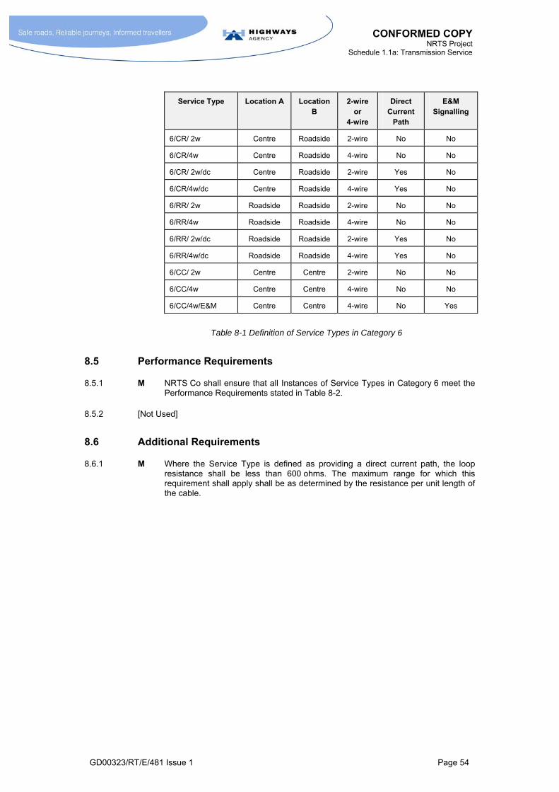
CONFORMED COPY NRTS Project
Schedule 1.1a: Transmission Service
GD00323/RT/E/481 Issue 1 Page 54
Service Type Location A Location B
2-wire or
4-wire
Direct Current
Path
E&M Signalling
6/CR/ 2w Centre Roadside 2-wire No No
6/CR/4w Centre Roadside 4-wire No No
6/CR/ 2w/dc Centre Roadside 2-wire Yes No
6/CR/4w/dc Centre Roadside 4-wire Yes No
6/RR/ 2w Roadside Roadside 2-wire No No
6/RR/4w Roadside Roadside 4-wire No No
6/RR/ 2w/dc Roadside Roadside 2-wire Yes No
6/RR/4w/dc Roadside Roadside 4-wire Yes No
6/CC/ 2w Centre Centre 2-wire No No
6/CC/4w Centre Centre 4-wire No No
6/CC/4w/E&M Centre Centre 4-wire No Yes
Table 8-1 Definition of Service Types in Category 6
8.5 Performance Requirements
8.5.1 M NRTS Co shall ensure that all Instances of Service Types in Category 6 meet the Performance Requirements stated in Table 8-2.
8.5.2 [Not Used]
8.6 Additional Requirements
8.6.1 M Where the Service Type is defined as providing a direct current path, the loop resistance shall be less than 600 ohms. The maximum range for which this requirement shall apply shall be as determined by the resistance per unit length of the cable.

CONFORMED COPY NRTS Project
Schedule 1.1a: Transmission Service
GD00323/RT/E/481 Issue 1 Page 55
Parameter Frequency Range for Requirement
Requirement
Nominal insertion loss at 800Hz for 2-wire Service Types
3dB
Nominal insertion loss at 800Hz for 4-wire Service Types
0dB
Loss/Frequency response relative to the loss at 800Hz
(+ means more loss)
300 – 500Hz -2 to +6dB
500 – 2000Hz -1 to +3dB
2000–2600Hz -1 to +3dB
2600 – 2800Hz -1 to +3dB
2800 – 3000Hz -2 to +6dB
Group delay/frequency response relative to minimum group delay
500 – 600Hz 3000s
600 – 1000Hz <1500s
1000 – 2600Hz <500s
2600 – 2800Hz <3000s
Random noise level <-45 dBm0p
Impulsive noise threshold (no more than 18 impulsive noise counts to exceed the threshold limit in any period of 15 minutes)
<-21dBm0p
Signal-to-listener echo ratio >20dB
Crosstalk attenuation >45dB
Signal-to-quantizing noise ratio >22dB
Maximum frequency error 2Hz
Phase jitter <10o
Input impedance 600 ohms, nominal. May vary between 450 ohms and 750 ohms.
Table 8-2 Performance Requirements for Category 6 Service Types

CONFORMED COPY NRTS Project
Schedule 1.1a: Transmission Service
GD00323/RT/E/481 Issue 1 Page 56
9 TRANSMISSION SERVICE CATEGORY 7 – GENERIC PUBLIC TELECOMMUNICATION SERVICES
9.1 [Not Used]
9.2 [Not Used]
9.3 [Not Used]
9.4 [Not Used]
9.5 Requirements
9.5.1 M A Service Category 7 service shall be defined as any Public Telecommunications Operator (PTO) telecommunications service used directly by the HA for which NRTS Co undertakes supply management on behalf of the HA. For the avoidance of doubt, Service Category 7 shall not include the following:
a) PTO services that form part of the supply of STIs in other Service Categories;
b) PTO services that otherwise form an integral element of the NRTS Co network, network management arrangements, or systems solutions;
c) PTO services procured by NRTS Co to support NRTS Co operations (such as telecommunications services used by staff); and,
d) all forms of Designated Link.
9.5.2 M For Service Category 7 services, NRTS Co shall not be responsible for the technical performance characteristics of the telecommunications service.
9.5.3 M NRTS Co shall adopt a particular PTO telecommunications service as a Service Category 7 service when instructed to do so by the HA. NRTS Co shall handback its responsibilities under Service Category 7 with regard to a particular PTO telecommunications service when instructed to do so by the HA.
9.5.4 M NRTS Co shall maintain records of all services that fall within the scope of Service Category 7 on the NRTS Service Schedule in accordance with Schedule 1.2 paragraph 5.10.5.4.
9.5.5 M NRTS Co’s responsibilities in relation to Service Category 7 services include:
facilitating the transfer of existing contracts with PTOs from the HA to NRTS Co, as and when the HA instructs NRTS Co to facilitate such transfers;
creating new contracts between PTO suppliers and NRTS Co, as instructed by the HA;
managing such contracts as have been transferred to NRTS Co or which have been created by NRTS Co on behalf of the HA;
facilitating the transfer of existing contracts with PTOs from NRTS Co to the HA, as and when the HA instructs NRTS Co to facilitate such transfers;
managing the installation and commissioning of new services supplied by PTOs;
undertaking acceptance testing of such services at the Service Delivery Point;
CONFORMED COPY NRTS Project
Schedule 1.1a: Transmission Service
GD00323/RT/E/481 Issue 1 Page 57
monitoring service performance;
managing faults;
reporting on utilisation; and,
trend analysis.
9.5.6 M NRTS Co shall use reasonable endeavours to obtain SC7 services at the most commercially advantageous terms to the HA.
9.5.7 M NRTS Co shall act promptly in response to any faults reported by PTOs. NRTS Co shall make use of any services (manual or automatic) that the PTO provides to inform users of current faults or planned service outages.
9.5.8 M In accordance with the Fault Notification Procedure given in Schedule 1.2 section 5.4.2.24, NRTS Co shall inform the relevant PTO within 5 minutes of a fault:
being reported to NRTS Co by the HA or parties designated by the HA;
being detected by NRTS Co; or,
otherwise being brought to the attention of NRTS Co.
9.5.9 M In accordance with the Fault Notification Procedure given in Schedule 1.2 section 5.4.2.24, NRTS Co shall inform the HA within 5 minutes of:
NRTS Co being informed of a fault by the PTO;
the fault being detected by NRTS Co;
NRTS Co otherwise becoming aware, or being informed, of the fault.
9.5.10 M In relation to Service Category 7 services NRTS Co shall:
a) determine promptly the details and expected length of any interruption of a service and pass this information to the HA in accordance with Schedule 1.2 section 5.4.2.26;
b) inform the HA of any outages planned by a PTO to such services:
c) track progress with rectification activities undertaken by PTOs;
d) be proactive in ensuring that PTOs meet their commitments with regard to restoring service;
e) escalate and inform PTOs of impending violations in service level agreements.
9.5.11 M In relation to Service Category 7 services, NRTS Co shall:
require PTOs to submit performance reports against service level agreements for NRTS Co to use in monitoring performance on behalf of the HA;
use reasonable endeavours to procure that PTOs meet their service level agreements;
undertake trend analysis of data made available by PTOs and include in reports to HA.
9.5.12 M In relation to Service Category 7 services NRTS Co shall deliver the services in accordance with the programme agreed in a Task Authorisation Form in relation to:
orders for new services;
orders for changes to existing services;
orders to terminate services.

CONFORMED COPY NRTS Project
Schedule 1.1a: Transmission Service
GD00323/RT/E/481 Issue 1 Page 58
9.5.13 M NRTS Co is to inform the HA of progress in relation to each of the activities identified in paragraph 9.5.12. NRTS Co shall promptly inform the HA of any delays that have occurred or which it understands will occur in relation to these activities.
9.5.14 M NRTS Co shall ensure that Service Category 7 services are set-up to the relevant standards and correctly commissioned.
9.5.15 M In relation to Service Category 7 services NRTS Co shall:
track contract renewal periods and ensure that appropriate actions are being undertaken to ensure continuity of service in relation to contracts that are about to expire;
validate billing information;
consolidate all PTO invoices into a single invoice for the HA;
manage the recovery of compensation due to the HA in relation to service level agreements with PTOs;
collect, validate, and collate reports from all PTOs into one concise report.
9.5.16 M NRTS Co shall make available a monthly report to the HA containing all relevant information including:
a) summary information on the number of services for each type of service and for each PTO;
b) summary of status of orders, highlighting delays, for:
new services;
changes to existing services;
terminating services;
c) reports on all of the following indicators of PTO performance by service and PTO:
availability %;
service downtime;
restoration times;
fault information;
deviations from service level agreement;
d) analysis of trends including trend relating to performance indicators identified in c);
e) any inaccuracies identified in the invoices issued by PTOs;
f) compensation received as a percentage of compensation due from PTOs for not meeting service level targets;
g) comparisons of PTO services by category.
9.5.17 [Not Used]
CONFORMED COPY NRTS Project
Schedule 1.1a: Transmission Service
GD00323/RT/E/481 Issue 1 Page 59
10 TRANSMISSION SERVICE CATEGORY 8 – GENERIC IP SERVICE
10.1 [Not Used]
10.2 [Not Used]
10.3 Introduction to Service Types in Category 8
10.3.1 M The Service Types fall into two broad classes:
Roadside-to-Centre Service Types - these support IP traffic flows to and from a roadside SDP. They are known as Service Type 8Rx, where x is the Access Line Bandwidth (refer to Table 10-1 including Note 1).
Centre-to-Centre Service Types - these support IP traffic flows between COs or other office locations. They are known as Service Type 8Cx, where x is the Access Line Bandwidth (refer to Table 10-2).
10.3.2 M The Service Types in this Category are characterised by their Access Line Bandwidths. This is the maximum rate that data can be transported to and from the Service Delivery Points, and is defined in paragraph 10.4.4.
10.3.3 [Not Used]
10.3.4 M The nomenclature of the Service Types is indicated by the following examples:
8R 33k is a Roadside-to-Centre Service Type with an Access Line Bandwidth of 33.6kbps. The “R” indicates roadside;
8R 1M is a Roadside-to-Centre Service Type with an Access Line Bandwidth of 1.024Mbps;
8C 2M is a Centre-to-Centre Service Type with an Access Line Bandwidth of 2.048Mbps. The “C” indicates Centre.
10.3.5 M The full range of Service Types for Service Category 8 is listed in Table 10-1 (including Note 1) and Table 10-2.
Figure 10-1 [Not Used]

CONFORMED COPY NRTS Project
Schedule 1.1a: Transmission Service
GD00323/RT/E/481 Issue 1 Page 61
10.4 Definition of Terms
10.4.1 [Not Used]
Definition: IP Network
10.4.2 M The IP Network shall be defined as a network that is capable of transporting IP datagrams between any Service Delivery Points associated with any Instances of Service Types falling under Service Category 8.
10.4.3 [Not Used]
Definition: Access Line Bandwidth
10.4.4 [Not Used]
10.4.5 [Not Used]
10.4.6 [Not Used]
10.4.7 M The Access Line Bandwidth of an SDP shall be defined in terms of the reference model shown in Figure 10-2. It shall be defined as the data rate “B” (measured at the Physical Layer of the OSI model) that would be required on the data link shown in the reference model, for the reference model and the real SDP to exhibit “equivalent performance” with regard to the transport of IP data, where:
the reference model uses HDLC framing at the Data Link Layer (or a Data Link Layer protocol of similar efficiency);
the proportion of link capacity required for management information, and hence not available for the transport of user data, is what would typically be expected for data link in an IP network;
“equivalent performance” means that the maximum sustained throughput of IP datagrams that can be supported without packet loss is the same for both the reference model and the real SDP.
10.4.8 [Not Used]
10.4.9 [Not Used]
Interface Speed
10.4.10 [Not Used]
10.4.11 [Not Used]
10.4.11.1 M For the avoidance of doubt, the speed associated with the Interface Type shall not be taken as indicating the Access Line Bandwidth of a Service Type e.g. a Service Type with an Access Line Bandwidth of 256kbps may be supplied with an Ethernet 100BaseT interface (with a nominal speed of 100Mbps).

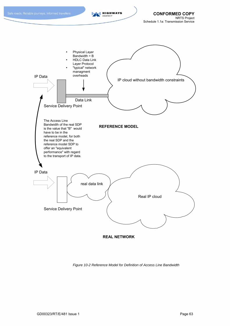
CONFORMED COPY NRTS Project
Schedule 1.1a: Transmission Service
GD00323/RT/E/481 Issue 1 Page 63
Figure 10-2 Reference Model for Definition of Access Line Bandwidth
real data link
IP cloud without bandwidth constraints
Service Delivery Point
IP Data
Physical LayerBandwidth = B
HDLC Data LinkLayer Protocol
"typical" networkmanagmentoverheads
REFERENCE MODEL
REAL NETWORK
Service Delivery Point
Data Link
Real IP cloud
IP Data
The Access LineBandwidth of the real SDPis the value that "B" wouldhave to be in thereference model, for boththe real SDP and thereference model SDP tooffer an "equivalentperformance" with regardto the transport of IP data.
CONFORMED COPY NRTS Project
Schedule 1.1a: Transmission Service
GD00323/RT/E/481 Issue 1 Page 64
Access Line Utilisation
10.4.12 [Not Used]
10.4.13 [Not Used]
10.4.14 M The Access Line Utilisation of an SDP shall be defined as the ratio of the average actual throughput of IP data to the maximum potential throughput of IP data that could be supported by the Access Line Bandwidth associated with that SDP.
Access Line Utilisation = average actual throughput of IP data maximum potential throughput of IP data
10.4.15 [Not Used]
10.4.16 [Not Used]
10.4.17 [Not Used]
10.5 Definition of Roadside-to-Centre Service Type: Service Type 8Rx
10.5.1 [Not Used]
10.5.2 M An Instance of Service Type 8Rx (where x takes one of the values between 1k2 and 100M indicated in the first column of Table 10-1) shall be defined as the supply of:
An SDP in a roadside cabinet (SDP 8Rx-2) that provides access to the IP Network;
the transport across the IP Network of any IP datagram originating from that SDP to any other SDP (including those belonging to Instances of other Service Types in Service Category 8) at any location on the IP Network; and,
the transport across the IP Network of any IP datagram terminating at that SDP from any other SDP (including those belonging to Instances of other Service Types in Service Category 8) at any location on the IP Network;
an SDP (SDP 8R–1) at the CO (which may be shared with a number of Instances of any Service Type 8Rx, see paragraph 10.5.6).
10.5.3 M For each Service Type the Access Line Bandwidth of the roadside SDP (i.e. SDP 8Rx-2) shall be as defined in Table 10-1.
10.5.4 [Not Used]
10.5.5 M NRTS Co shall make available the range of Interface Types for the roadside SDP (i.e. SDP 8Rx-2) listed in Table 10-1.
10.5.6 M As part of the delivery of all Instances of Service Type 8Rx in a particular CO area, NRTS Co shall be responsible for:
the provision of a suitable SDP (SDP 8R–1) at the CO;
the supply of the associated Access Line Bandwidth to support the transmission of IP data to and from the CO SDP.
CONFORMED COPY NRTS Project
Schedule 1.1a: Transmission Service
GD00323/RT/E/481 Issue 1 Page 65
10.5.7 M The interfacing arrangements at the CO shall be defined in the Service Solution Specification produced prior to, and finally agreed in, the Get Consent to Service Solution process (Schedule 1.2 section 4.3). A range of possible arrangements shall be offered to the HA including:
a common SDP shared by all Instances of all Roadside-to-Centre Service Types;
separate SDPs for different groupings of Service Type Instances (STIs). These groupings could be by Service Type, function or geographical location of the roadside SDP;
multiple interfaces to improve resilience or to offer better traffic management.
10.5.8 M A Registered Document containing the information identified in Annex B.1 shall be fully developed by NRTS Co for Service Type 8Rx as part of the Service Solution Specification prior to the Get Consent to Service Solution process (Schedule 1.2 section 4.3).
10.5.9 [Not Used]
10.5.10 [Not Used]
Sub-Type with Diverse Routing (SDP not in G-Cabinet, ATMg Cabinet or equivalent)
10.5.11 [Not Used]
10.5.12 M An Instance of Service Type 8RDx shall be defined as equivalent to an Instance of Service Type 8Rx (defined in paragraphs 10.5.2 to 10.5.10) with the additional requirement that Diverse Routing (see paragraph 15.14.1) shall be deployed by NRTS Co for the path from the roadside SDP.
10.5.12.1 M Service Type 8RDx shall not be deployed where the roadside SDP is located within either a G-Cabinet, an ATMg Cabinet or a cabinet containing an equivalent network node. In such case Service Type 8RDCabx shall be deployed.
Sub-Type with Diverse Routing located (SDP in G–Cabinet, ATMg Cabinet or equivalent)
10.5.12.2 M An Instance of Service Type 8RDCabx shall be defined as equivalent to an Instance of Service Type 8Rx (defined in paragraphs 10.5.2 to 10.5.10) with the following changes:
Service Type 8RDCabx shall only be available where the roadside SDP is located within a G-Cabinets an ATMg Cabinet or a cabinet containing an equivalent network node;
Diverse Routing shall be deployed by NRTS Co for the path from the roadside SDP;
the range of Access Line Bandwidths and Interface Types shall be as shown for Service Type 8RDCabx in Table 10-1.
CONFORMED COPY NRTS Project
Schedule 1.1a: Transmission Service
GD00323/RT/E/481 Issue 1 Page 66
Sub-Type with Multidrop and Diverse Routing
10.5.13 M An Instance of Service Type 8RMD shall be defined as equivalent to an Instance of Service Type 8Rx (defined in paragraphs 10.5.2 to 10.5.10) with the following changes:
Diverse Routing shall be deployed by NRTS Co for the path from the roadside SDP;
different SPC Rules (including those relating to Enablements) shall apply (see Annex H).
This Service Type shall be priced by Step 1b (see Schedule 1.2 for meaning of “Step 1b”).
Sub-Type that provides an Aggregation Point
10.5.14 M An Instance of Service Type 8RAx shall be as Service Type 8Rx except that each STI shall support up to 3 Service Delivery Points located within the a common type 600 cabinet (or equivalent enclosure.
Sub-Type to provide IP in association with Service Type 10AP/10AF
10.5.15 M An Instance of Service Type 8RPTZ shall be defined as equivalent to an Instance of Service Type 8Rx, except that:
an STI will only be available where an Instance of Service Type 10AP/10AF is required, with SDP 8RPTZ-2 located in the cabinet that houses SDP 10AP-1;
the SDP 8RPTZ-2 will only be required to support an Ethernet interface.
10.5.16 [Not Used]
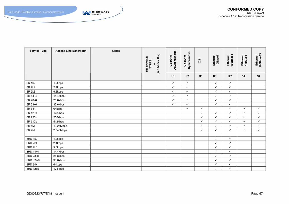
CONFORMED COPY NRTS Project
Schedule 1.1a: Transmission Service
GD00323/RT/E/481 Issue 1 Page 67
V.2
4/V
.28,
A
syn
ch
ron
ou
s
V.2
4/V
.28,
S
ynch
ron
ou
s
X.2
1
Eth
ern
et
10B
aseT
Eth
ern
et
100B
ase
T
Eth
ern
et
10B
asF
X
Eth
ern
et
100B
ase
FX
Service Type Access Line Bandwidth Notes
INT
ER
FA
CE
T
YP
ES
(s
ee A
nn
ex B
.2)
L1 L2 M1 R1 R2 S1 S2
8R 1k2 1.2kbps
8R 2k4 2.4kbps
8R 9k6 9.6kbps
8R 14k4 14.4kbps
8R 28k8 28.8kbps
8R 33k6 33.6kbps
8R 64k 64kbps
8R 128k 128kbps
8R 256k 256kbps
8R 512k 512kbps
8R 1M 1.024Mbps
8R 2M 2.048Mbps
8RD 1k2 1.2kbps
8RD 2k4 2.4kbps
8RD 9k6 9.6kbps
8RD 14k4 14.4kbps
8RD 28k8 28.8kbps
8RD 33k6 33.6kbps
8RD 64k 64kbps
8RD 128k 128kbps
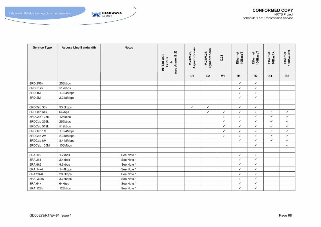
CONFORMED COPY NRTS Project
Schedule 1.1a: Transmission Service
GD00323/RT/E/481 Issue 1 Page 68
V.2
4/V
.28,
A
syn
ch
ron
ou
s
V.2
4/V
.28,
S
ynch
ron
ou
s
X.2
1
Eth
ern
et
10B
aseT
Eth
ern
et
100B
ase
T
Eth
ern
et
10B
asF
X
Eth
ern
et
100B
ase
FX
Service Type Access Line Bandwidth Notes
INT
ER
FA
CE
T
YP
ES
(s
ee A
nn
ex B
.2)
L1 L2 M1 R1 R2 S1 S2
8RD 256k 256kbps
8RD 512k 512kbps
8RD 1M 1.024Mbps
8RD 2M 2.048Mbps
8RDCab 33k 33.6kbps
8RDCab 64k 64kbps
8RDCab 128k 128kbps
8RDCab 256k 256kbps
8RDCab 512k 512kbps
8RDCab 1M 1.024Mbps
8RDCab 2M 2.048Mbps
8RDCab 8M 8.448Mbps
8RDCab 100M 100Mbps
8RA 1k2 1.2kbps See Note 1
8RA 2k4 2.4kbps See Note 1
8RA 9k6 9.6kbps See Note 1
8RA 14k4 14.4kbps See Note 1
8RA 28k8 28.8kbps See Note 1
8RA 33k6 33.6kbps See Note 1
8RA 64k 64kbps See Note 1
8RA 128k 128kbps See Note 1

CONFORMED COPY NRTS Project
Schedule 1.1a: Transmission Service
GD00323/RT/E/481 Issue 1 Page 69
V.2
4/V
.28,
A
syn
ch
ron
ou
s
V.2
4/V
.28,
S
ynch
ron
ou
s
X.2
1
Eth
ern
et
10B
aseT
Eth
ern
et
100B
ase
T
Eth
ern
et
10B
asF
X
Eth
ern
et
100B
ase
FX
Service Type Access Line Bandwidth Notes
INT
ER
FA
CE
T
YP
ES
(s
ee A
nn
ex B
.2)
L1 L2 M1 R1 R2 S1 S2
8RA 256k 256kbps See Note 1
8RA 512k 512kbps See Note 1
8RA 1M 1.024Mbps See Note 1
8RA 2M 2.048Mbps See Note 1
8RPTZ 1k2 1.2kbps
8RPTZ 2k4 2.4kbps
8RPTZ 9k6 9.6kbps
8RPTZ 14k4 14.4kbps
8RPTZ 28k8 28.8kbps
8RPTZ 33k6 33.6kbps
8RPTZ 64k 64kbps
8RPTZ 128k 128kbps
8RPTZ 256k 256kbps
8RPTZ 512k 512kbps
8RPTZ 1M 1.024Mbps
8RPTZ 2M 2.048Mbps
Note 1: For Service Type 8RA, the sum of the SDP interface speeds associated with a particular Service Type Instance shall be less or equal to 2Mbps
Table 10-1 Service Category 8 Definitions for Centre-to-Roadside IP Service Types

CONFORMED COPY NRTS Project
Schedule 1.1a: Transmission Service
GD00323/RT/E/481 Issue 1 Page 71
10.6 Definition of Centre-to-Centre Service Type: Service Type 8Cx
10.6.1 M An Instance of Service Type 8Cx (where x takes one of the values between 33k and 100M indicated in the first column of Table 10-2) shall be defined as the supply of:
a SDP (SDP 8Cx-1) at a CO (or other SPC D location - refer to Annex H.1) that provides access to the IP Network;
the transport across the IP Network of any IP datagram originating from that SDP to any other SDP (including those belonging to an Instance of other Service Types in Service Category 8) at any location on the IP Network; and,
the transport across the IP Network of any IP datagram terminating at that SDP from any other SDP (including those belonging to Instances of other Service Types in Service Category 8) at any location on the IP Network.
10.6.2 M The Access Line Bandwidth available for use in communicating with other Instances of Service Type 8Cx shall be as defined in Table 10-2. Such Access Line Bandwidth shall be treated as additional to any Access Line Bandwidth provided to support Instances of Service Type 8Rx.
10.6.3 [Not Used]
10.6.4 [Not Used]
10.6.5 M NRTS Co shall make available the range of Interface Types for SDP 8Cx-1 listed in Table 10-2.


CONFORMED COPY NRTS Project
Schedule 1.1a: Transmission Service
GD00323/RT/E/481 Issue 1 Page 73
V.2
4/V
.28,
A
syn
ch
ron
ou
s
V.2
4/V
.28,
S
ynch
ron
ou
s
X.2
1
Eth
ern
et
10B
aseT
Eth
ern
et
100B
ase
T
Eth
ern
et
10B
asF
X
Eth
ern
et
100B
ase
FX
Service Type Access Line Bandwidth
INT
ER
FA
CE
T
YP
ES
(s
ee A
nn
ex B
.2)
L1 L2 M1 R1 R2 S1 S2
8C 33k 33.6kbps
8C 64k 64kbps
8C 128k 128kbps
8C 256k 256kbps
8C 512k 512kbps
8C 1M 1.024Mbps
8C 2M 2.048Mbps
8C 8M 8.448Mbps
8C 100M 100Mbps
Table 10-2 Service Category 8 Definitions for Centre-to-Centre IP Service Types


CONFORMED COPY NRTS Project
Schedule 1.1a: Transmission Service
GD00323/RT/E/481 Issue 1 Page 75
10.7 [Not Used]
Table 10-3 [Not Used]
Table 10-4 [Not Used]
10.8 Performance Requirements
10.8.1 [Not Used]
IP Throughput
10.8.2 M The methodology for measuring IP throughput shall be defined as part of the Get Consent to Service Solution process. This methodology:
shall be consistent with the definition of Access Line Bandwidth given in paragraph 10.4.7;
shall follow Good Industry Practice;
for the avoidance of doubt, shall take into account all constraints on IP throughput between the source and destination SDPs.
10.8.3 M NRTS Co shall continuously monitor various network parameters to indicate whether constraints on IP throughput are occurring. The means of achieving this shall be defined as part of the Get Consent to Service Solution process (Schedule 1.2 section 4.3). Such an approach shall include monitoring queue length and lost packets at various routers throughout the IP Network.
Packet Latency
10.8.4 M Packet Latency shall be defined as the time taken for an IP datagram to travel between its source SDP and its destination SDP. This subsumes all forms of delay associated with the movement of the IP datagram through the IP Network.
10.8.5 M NRTS Co shall ensure that the Packet Latency is less than, or equal to, L for all conditions of traffic up to the High Demand Conditions as defined in paragraph 10.8.6, where:
L = 15ms + S
where S = Serialisation Delay
Note: Packet Latency is defined in paragraph 10.8.4 in terms of one-way rather than round-trip delay.
10.8.5.1 M The Serialisation Delay (S) shall be defined as follows:
S = number of bits in IP Packet injected at source SDP
Access Line Bandwidth of STI

CONFORMED COPY NRTS Project
Schedule 1.1a: Transmission Service
GD00323/RT/E/481 Issue 1 Page 76
10.8.6 M High Demand Conditions shall be defined as the condition where:
all Instances of all Service Types in Service Category 8 are simultaneously being injected with traffic corresponding to 100% Access Line Utilisation; and,
the network is operating at the maximum level of traffic loading permitted by the Capacity Model rules in paragraph 17.5.13 (noting that this includes traffic from all Service Categories that use the network); and,
the network is experiencing the loading effects of NRTS Co’s internal network management traffic and any other traffic not attributable to the HA.
10.8.7 M NRTS Co shall measure Packet Latency using test equipment and procedures and operating conditions acceptable to the HA. The methodology for measuring Packet Latency shall be defined as part of the Get Consent to Service Solution process (Schedule 1.2 section 4.3).
10.8.8 M NRTS Co shall undertake the measurement of the Packet Latency:
as part of the Activate Service process (Schedule 1.2 section 6.5) for Service Type Instances, if requested by the HA;
if requested by the HA for the purpose of diagnosing performance problems associated with end applications;
on a routine sampling basis. This information shall be included in the monthly reports that NRTS Co makes to the HA (see paragraph 15.11.4). The reporting process shall be in accordance with the Manage Network process (Schedule 1.2 section 5.10).
Goodput Ratio
10.8.9 M The Goodput Ratio shall be defined as the percentage of IP datagrams originating from a source SDP that are successfully received by a destination SDP.
10.8.10 M NRTS Co shall ensure that the Goodput Ratio is better than 99.99% for all conditions of traffic less than High Demand Conditions as defined in paragraph 10.8.6.
10.8.11 M NRTS Co shall measure the Goodput Ratio using test equipment, procedures and operating conditions acceptable to the HA. The methodology for measuring Goodput Ratio shall be defined as part of the Get Consent to Service Solution process (Schedule 1.2 section 4.3).
10.8.12 M NRTS Co shall undertake the measurement of the Goodput Ratio:
as part of the Activate Service process (Schedule 1.2 section 6.5) for Service Type Instances, if requested by the HA;
if requested by the HA for the purpose of diagnosing performance problems associated with end applications;
on a routine sampling basis. This information shall be included in the monthly reports that NRTS Co makes to the HA (see paragraph 15.11.4.) The reporting process shall be in accordance with the Manage Network process (Schedule 1.2 section 5.10).

CONFORMED COPY NRTS Project
Schedule 1.1a: Transmission Service
GD00323/RT/E/481 Issue 1 Page 77
Performance Requirements: Packet Loss
10.8.13 [Not Used]
10.8.14 M Packet Loss shall be defined as the total number of packets lost for all Service Types supported by the IP Network divided by the total number of packets transmitted, over the sampling period.
10.8.15 M NRTS Co shall ensure that the Packet Loss associated with the total traffic from all Instances of all Service Types in Transmission Service Category 8 is less than 0.01% over a sampling period of one month.
10.8.16 M NRTS Co shall report on Packet Loss on a routine basis. This information shall be included in the monthly reports that NRTS Co makes to the HA (see paragraph 15.11.4). The reporting process shall be in accordance with the Manage Network process (Schedule 1.2 section 5.10). The methodology for measuring Packet Loss shall be defined as part of the Get Consent to Service Solution process (Schedule 1.2 section 4.3).
10.9 Additional Requirements
Network Standards
10.9.1 M The IP Network shall be compatible with the requirements of IP version 4 as defined by the relevant “Request For Comment” (RFC) documents produced by the Internet Engineering Task Force (IETF). NRTS Co shall upgrade the IP Network to support IP version 6 at no additional charge, subject to the written agreement of the HA.
10.9.2 M NRTS Co shall be responsible for periodically upgrading the IP Network to offer Service Types that use current industry standards, according to the Configuration Management requirements of the Manage Network process (Schedule 1.2 section 5.10).
10.9.3 [Not Used]
10.9.3.1 [Not Used]
10.9.3.2 [Not Used]
10.9.3.3 M The IP Network shall support appropriate queuing and prioritisation mechanisms. The IP Network shall support the DiffServ mechanism (as defined in the IETF’s RFC 2475). The IP Network shall also be capable of classifying packets at the point of ingress based on:
physical port;
IP destination address, source address or combination of source and destination address;
TCP port or UDP port address;
source and destination MAC address;
IEE 802.1Q/p.
10.9.3.4 [Not Used]

CONFORMED COPY NRTS Project
Schedule 1.1a: Transmission Service
GD00323/RT/E/481 Issue 1 Page 78
10.9.3.5 M NRTS Co shall use open standards in the IP Network. This shall include standards relating to:
addressing;
queuing/prioritisation;
routing protocols;
interface standards.
10.9.3.6 [Not Used]
10.9.3.7 M NRTS Co shall ensure that the IP Network supports multicasting.
10.9.3.8 [Not Used]
10.9.3.9 M NRTS Co shall ensure that the IP Network has the capability to support timing messages to enable HA Applications to be synchronised. In particular, it shall be possible to use these timing messages to permit HA Applications associated with SDPs located within 1km of each other to be synchronised such that maximum timing difference is less than 9ms.
10.9.3.10 M NRTS Co shall incorporate features in its solution to monitor and rate-limit the IP traffic flow associated with each STI.
10.9.3.11 M The NRTS Co Service Types in Service Category 8 shall be capable of being configured as a bridged Ethernet service (RFC1483) that emulates the characteristics of the service used to provide video and data links between the TCC and COs. In delivering this requirement NRTS Co shall not be responsible for any equipment that lies on the HA side of the SDP.
Interfaces: Data Link Layer Requirements
10.9.4 [Not Used]
10.9.5 M (In relation to X.21 and V.24 interfaces only) NRTS Co shall offer interfaces that support, as a minimum, HDLC (without LAPB2) and PPP.
Addressing Requirements
10.9.6 M NRTS Co shall support the following addressing options for Service Category 8 both options shall also support the use of Domain Names by use of Domain Name Servers provided and managed by NRTS Co.
Dynamic Addressing: a mechanism shall be provided to allow end devices to request a network address during session establishment (e.g. when a new device is connected or when it is powered up again following repair work); and
Static Addressing: NRTS Co shall administer the allocation of fixed network addresses on a call-off basis that end-application developers can hard-wire into their applications.
2 HDLC = High-Level Data Link Control.
LAPB = Link Access Procedure, Balanced.
PPP = Point-to-Point Protocol.

CONFORMED COPY NRTS Project
Schedule 1.1a: Transmission Service
GD00323/RT/E/481 Issue 1 Page 79
10.9.7 [Not Used]
10.9.8 M NRTS Co shall implement systems supporting Dynamic Addressing in such a manner that they offer an appropriate degree of diversity and resilience to failure of network elements.
10.9.8.1 M Without prejudice to paragraph 10.9.8, NRTS Co shall provide resilient Domain Name Servers and resilient Dynamic Host Configuration Protocol servers in each of the 7 Regional Control Centres (RCCs).
10.9.9 [Not Used]
Upgrading existing IP services
10.9.10 [Not Used]
10.9.11 M NRTS Co shall upgrade (at its own cost) by the Build Completion Date and in accordance with the Build Transmission Service process in Schedule 1.2 paragraph 8.7.4.3 any IP services that have been implemented by the HA prior to Take-On of Service Category 8 as part of:
the Active Traffic Management (ATMg) trial on M42 Junction 4a to 7. This shall be limited to 12 STIs with Access Line Bandwidths of up to 2Mbps;
the Hampshire CCTV project. This shall be limited to 9 STIs with Access Line Bandwidths of up to 2Mpbs.
10.9.11.1 M In addition to the paragraph 10.9.11, NRTS Co shall upgrade (at its own cost) any IP services that have been implemented by the HA prior to the Generic Service Start Date provided that the equipment that supports the link between the Transmission Station and the Roadside SDP does not require material change. Such upgrades shall be completed by NRTS Co by the later of:
within 6 months of the PCO Area in which the service resides being migrated to an RCC; and
the Build Completion Date.
NRTS Co shall carry out the relevant Service Category 8 Transmission Station Enablements where the IP services make use of Transmission Stations that have not been suitably Enabled. The HA shall pay NRTS Co the Standard Price for such Enablements. The HA shall instruct NRTS Co to undertake an HA Planned Outage of 2 hours or less to permit such upgrades to take place. The timing of such HA Planned Outages shall be agreed in advance between NRTS Co and the HA.

CONFORMED COPY NRTS Project
Schedule 1.1a: Transmission Service
GD00323/RT/E/481 Issue 1 Page 80
10.9.11.2 M Prior to the Generic Service Start Date, but after Take-On of a Service Area, NRTS Co shall, in response to requests from the HA, Provision Hybrid Service Category 8 Service Types. A Hybrid Service Category 8 Service Type shall be defined as a Service Type that use a similar technical solution to Service Category 8 on the path between the Transmission Station and the roadside SDP but uses either an SDH or PDH link for the path between the Transmission Station and the CO. NRTS Co shall be obliged to offer such Service Types where the existing SDH or PDH arrangements provide sufficient capacity and a suitable interface in the Transmission Station to support NRTS Co’s Service Category 8 roadside solution. Such Hybrid Service Types shall be priced at:
the Standard Provisioning Charge for Service Type 8Rx;
the appropriate TS Service Category 8 Enablement (where Enablement is required).
Once the Base Network has been extended to support that Transmission Station it shall be regarded as being Enabled for Service Category 8 and any existing hybrid Service Types will be transferred to the new network at no extra charge.
10.9.12 [Not Used]
10.10 Supporting TCC to CO services
10.10.1 [Not Used]
10.10.2 [Not Used]
10.10.3 [Not Used]
10.10.4 [Not Used]
10.10.5 [Not Used]
10.10.6 [Not Used]
10.10.7 M NRTS Co shall continue to support any existing arrangements that use a Bridged Ethernet service (RFC1483) to provide links between the TCC and COs. NRTS Co shall, subject to the consent of the HA, transfer such services on to the NRTS IP Network using a service that emulates the characteristics of the pre-existing Bridged Ethernet service in such a manner as to ensure continued operation of the HA end devices without need for re-configuration of those HA end devices.
10.10.8 M The Service Type Instances between the TCC and RCCs or PCOs provided by NRTS Co shall be such that the TCC video and data applications that these Service Types function satisfactorily.
10.10.9 [Not Used]
10.10.10 [Not Used]
10.11 [Not Used]
10.11.1 [Not Used]
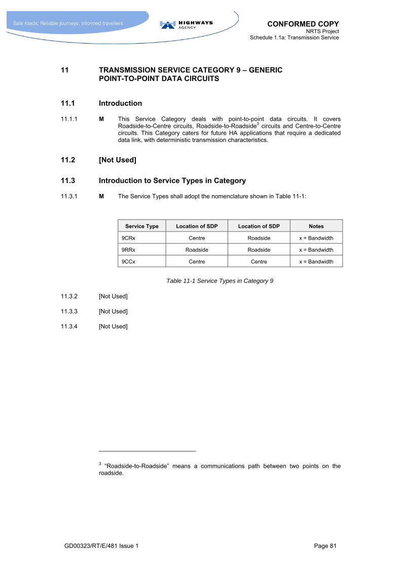
CONFORMED COPY NRTS Project
Schedule 1.1a: Transmission Service
GD00323/RT/E/481 Issue 1 Page 81
11 TRANSMISSION SERVICE CATEGORY 9 – GENERIC POINT-TO-POINT DATA CIRCUITS
11.1 Introduction
11.1.1 M This Service Category deals with point-to-point data circuits. It covers Roadside-to-Centre circuits, Roadside-to-Roadside3 circuits and Centre-to-Centre circuits. This Category caters for future HA applications that require a dedicated data link, with deterministic transmission characteristics.
11.2 [Not Used]
11.3 Introduction to Service Types in Category
11.3.1 M The Service Types shall adopt the nomenclature shown in Table 11-1:
Service Type Location of SDP Location of SDP Notes
9CRx Centre Roadside x = Bandwidth
9RRx Roadside Roadside x = Bandwidth
9CCx Centre Centre x = Bandwidth
Table 11-1 Service Types in Category 9
11.3.2 [Not Used]
11.3.3 [Not Used]
11.3.4 [Not Used]
3 “Roadside-to-Roadside” means a communications path between two points on the roadside.

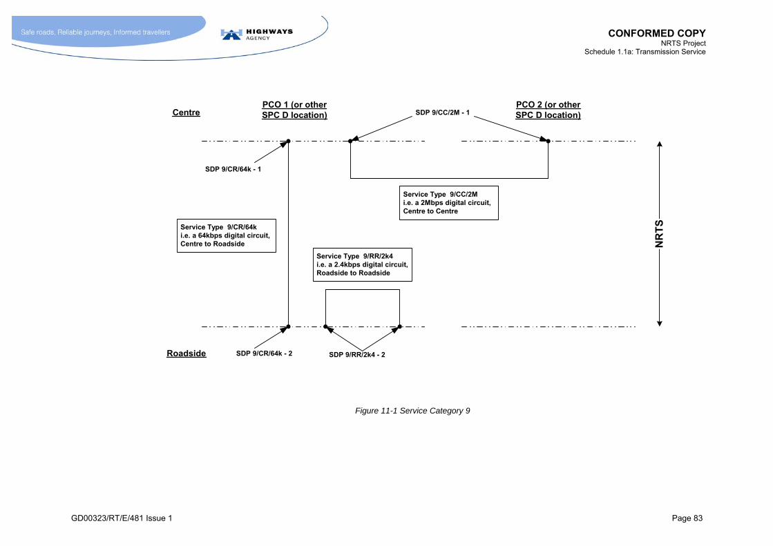
CONFORMED COPY NRTS Project
Schedule 1.1a: Transmission Service
GD00323/RT/E/481 Issue 1 Page 83
PCO 1 (or otherSPC D location)
Roadside
NR
TS
SDP 9/CR/64k - 2
PCO 2 (or otherSPC D location)
Service Type 9/CR/64ki.e. a 64kbps digital circuit,Centre to Roadside
SDP 9/CR/64k - 1
SDP 9/RR/2k4 - 2
Service Type 9/RR/2k4i.e. a 2.4kbps digital circuit,Roadside to Roadside
Centre SDP 9/CC/2M - 1
Service Type 9/CC/2Mi.e. a 2Mbps digital circuit,Centre to Centre
Figure 11-1 Service Category 9


CONFORMED COPY NRTS Project
Schedule 1.1a: Transmission Service
GD00323/RT/E/481 Issue 1 Page 85
11.4 Definition of Service Types 9 CRx, 9RRx, 9CCx
11.4.1 M An Instance of Service Type 9CRx (where x takes one of the values shown in Table 11-2) shall be defined as the provision of a point-to-point link between the following pairs of SDPs:
SDP 9CRx-1 at the CO; and
SDP 9CRx-2 at the roadside.
11.4.2 M An Instance of Service Type 9RRx (where x takes one of the values shown in Table 11-2) shall be defined as the provision of a point-to-point link between the following pairs of SDPs:
SDP 9RRx-2 at the roadside; and
another SDP 9RRx-2 at the roadside.
11.4.3 M An Instance of Service Type 9CCx (where x takes one of the values shown in Table 11-2) shall be defined as the provision of a point-to-point link between the following pairs of SDPs:
an instance of SDP 9CCx-1 at one CO (or other SPC D location - refer to Annex H.1); and
an instance of SDP 9CCx-1 at another CO (or other SPC D location).
11.4.4 M NRTS Co shall make available the range of Interface Types as listed in Table 11-2.
11.4.5 [Not Used]
11.4.6 [Not Used]
11.5 Performance Requirements
11.5.1 M The Service Types shall perform in accordance with the relevant International Telecommunications Union specifications. NRTS Co shall define fully the performance specifications as part of the Get Consent to Service Solution process (Schedule 1.2 section 4.3).
11.6 [Not Used]
11.7 [Not Used]
11.7.1 M The pricing of of the following shall be determined after the Execution Date as if they were Authority Service Variations:
All Service Types in Serviced Category 9 that have an Access Line Bandwidth in excess of 2.0488Mbps;
All Service Types in Service Category 8 (except 8RDCab series and the 8C series) that have an Access Line Bandwidth in excess of 2.0488Mbps.


CONFORMED COPY NRTS Project
Schedule 1.1a: Transmission Service
GD00323/RT/E/481 Issue 1 Page 87
INT
ER
AC
E
TY
PE
S
V.2
4/V
.28,
A
syn
ch
ron
ou
s
V.2
4/V
.28,
S
ynch
ron
ou
s
X.2
1
G70
3 (w
ith
G70
4 fr
ame
str
uc
ture
)
G70
3 (w
ith
G74
2 fr
ame
str
uc
ture
)
G70
3 (w
ith
G75
1 fr
ame
str
uc
ture
)
ST
M-1
(w
ith
G
957
Op
tica
l In
terf
ace
)
Roadside-to-Centre Service Type
Roadside-to-Roadside Service Type
Centre-to-Centre Service Type
Bandwidth
INT
ER
AC
E
TY
PE
D
ES
IGN
AT
ION
(A
NN
EX
B)
L1 L2 M1 N1 N2 N3 P1
9CR 1k2 9RR 1k2 1.2kbps
9CR 2k4 9RR 2k4 2.4kbps
9CR 9k6 9RR 9k6 9CC 9k6 9.6kbps
9CR 14k4 9RR 14k4 9CC 14k4 14.4kbps
9CR 28k8 9RR 28k8 9CC 28k8 28.8kbps
9CR 33k6 9RR 33k6 9CC 33k6 33.6kbps
9CR 64k 9RR 64k 9CC 64k 64kbps
9CR 128k 9RR 128k 9CC 128k 128kbps
9CR 256k 9RR 256k 9CC 256k 256kbps
9CR 512k 9RR 512k 9CC 512k 512kbps
9CR 1M 9RR 1M 9CC 1M 1.024Mbps
9CR 2M 9RR 2M 9CC 2M 2.048Mbps
Table 11-2 Service Category 9 Bandwidths and Interface Types


CONFORMED COPY NRTS Project
Schedule 1.1a: Transmission Service
GD00323/RT/E/481 Issue 1 Page 89
12 TRANSMISSION SERVICE CATEGORY 10 – SWITCHED VIDEO SERVICES
12.1 [Not Used]
12.2 [Not Used]
Table 12-1 [Not Used]
12.3 [Not Used]
Table 12-2 [Not Used]
12.4 [Not Used]
12.5 Introduction to Definitions
12.5.1 M The realisation of Category 10 Service Types shall require NRTS Co to provide a Switched Video Network as represented in Figure 12-1. The Switched Video Network shall have the following characteristics:
the capability to link video input ports (typically connected to cameras) to one or many video output ports (typically connected to monitors or interfaces to links to support remote devices such as monitors);
the capability to transport video signals at a range of Picture Quality Levels;
the provision of adequate traffic handling capability to support the expected volumes of traffic;
the capability to carry out a range of service control tasks in response to commands across a Service Control Interface (with typically one Service Control Interface per RCC);
the capability to record, store and retrieve video images.
12.5.2 [Not Used]
12.5.3 [Not Used]
12.5.4 [Not Used]
12.5.5 [Not Used]
12.5.6 [Not Used]
12.5.7 [Not Used]

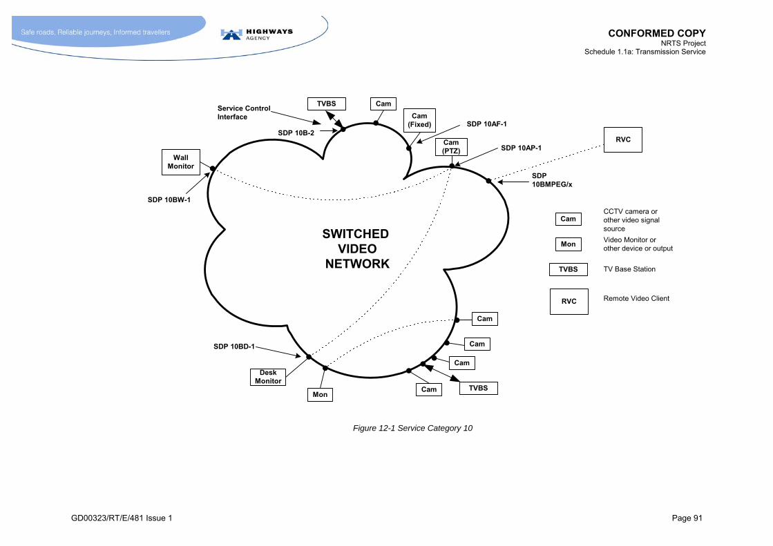
CONFORMED COPY NRTS Project
Schedule 1.1a: Transmission Service
GD00323/RT/E/481 Issue 1 Page 91
SWITCHED VIDEO
NETWORK
Mon
CamCCTV camera orother video signalsource
Video Monitor orother device or output
TV Base Station
WallMonitor
Mon
Cam
Cam
Cam
Cam
Cam(Fixed)
TVBS
TVBS
TVBS
Cam
Cam(PTZ)
SDP 10B-2
SDP 10AP-1
SDP 10BW-1
SDP 10AF-1
SDP 10BD-1
DeskMonitor
Service ControlInterface
RVC
RVC Remote Video Client
SDP10BMPEG/x
Figure 12-1 Service Category 10
CONFORMED COPY NRTS Project
Schedule 1.1a: Transmission Service
GD00323/RT/E/481 Issue 1 Page 92
12.6 Definition of Service Types
12.6.1 M An Instance of Service Type 10Ax (where x = P or F) shall be defined as
the provision of a video input port at the roadside (SDP 10Ax-1) connected to the Switched Video Network
such as to provide connectivity to any Instance or combination of Instances of Service Type 10Bx
at the various Picture Quality Levels appropriate to the combination of Service Types, as shown in Table 12-3.
12.6.2 M An Instance of Service Type 10Bx (where x = W, D, etc) shall be defined as
the provision of a video output port at a CO (SDP 10Bx-1) connected to the Switched Video Network
such as to provide connectivity to any Instance or Instances of Service Type 10Ax
at any of the various Picture Quality Levels appropriate to the combination of Service Types, as shown in Table 12-3.
12.7 Definition of Home Area, Community of Interest Area and Remote Area
12.7.1 M The Home Area for a PCO or RCC shall be defined as the geographical area that contains CCTV cameras that are normally controlled by that PCO or RCC.
12.7.2 [Not Used]
12.7.3 [Not Used]
12.7.4 [Not Used]
12.7.5 [Not Used]
12.7.6 [Not Used]
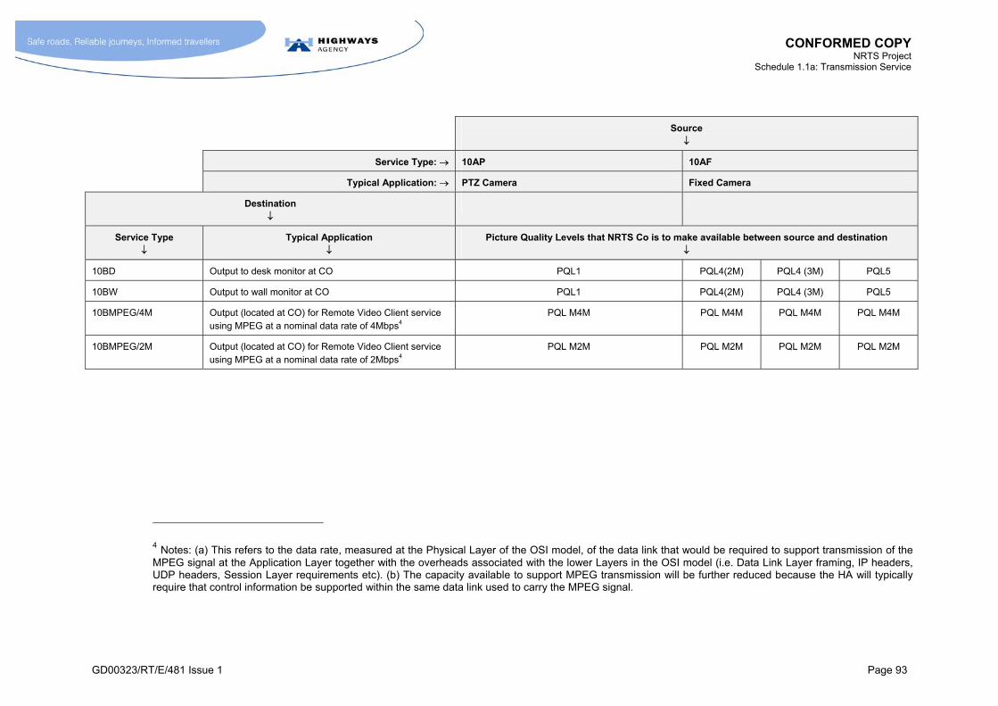
CONFORMED COPY NRTS Project
Schedule 1.1a: Transmission Service
GD00323/RT/E/481 Issue 1 Page 93
Source
Service Type: 10AP 10AF
Typical Application: PTZ Camera Fixed Camera
Destination
Service Type
Typical Application
Picture Quality Levels that NRTS Co is to make available between source and destination
10BD Output to desk monitor at CO PQL1 PQL4(2M) PQL4 (3M) PQL5
10BW Output to wall monitor at CO PQL1 PQL4(2M) PQL4 (3M) PQL5
10BMPEG/4M Output (located at CO) for Remote Video Client service using MPEG at a nominal data rate of 4Mbps4
PQL M4M PQL M4M PQL M4M PQL M4M
10BMPEG/2M Output (located at CO) for Remote Video Client service using MPEG at a nominal data rate of 2Mbps4
PQL M2M PQL M2M PQL M2M PQL M2M
4 Notes: (a) This refers to the data rate, measured at the Physical Layer of the OSI model, of the data link that would be required to support transmission of the MPEG signal at the Application Layer together with the overheads associated with the lower Layers in the OSI model (i.e. Data Link Layer framing, IP headers, UDP headers, Session Layer requirements etc). (b) The capacity available to support MPEG transmission will be further reduced because the HA will typically require that control information be supported within the same data link used to carry the MPEG signal.

CONFORMED COPY NRTS Project
Schedule 1.1a: Transmission Service
GD00323/RT/E/481 Issue 1 Page 94
Source
Service Type: 10AP 10AF
Typical Application: PTZ Camera Fixed Camera
Destination
Service Type
Typical Application
Range of Picture Quality Levels that NRTS Co is to make available between source and destination.
10BMPEG/256k Output (located at CO) for Remote Video Client service using MPEG at a nominal data rate of 256kbps4
PQL M256k PQL M256k
10BMPEG/128k Output (located at CO) for Remote Video Client service using MPEG at a nominal data rate of 128kbps4
PQL M128k PQL M128k
Table 12-3 Connectivity and Picture Quality Level Requirements for Service Types

CONFORMED COPY NRTS Project
Schedule 1.1a: Transmission Service
GD00323/RT/E/481 Issue 1 Page 95
Picture Quality Level Acceptable Picture Quality Limits on Video Path Latency (See paragraph 12.22.11.1)
PQL1 As defined in paragraph 12.8.1 <165ms,
PQL2 As defined in paragraph 12.8.1 <165ms
PQL3 As defined in paragraph 12.8.1 <165ms,
PQL4(2M) As PQL3 with exception of Video Path Latency. <915ms
PQL4(3M) As PQL3 with exception of Video Path Latency. <600ms
PQL5 As PQL1 with exception of Video Path Latency <415ms
Video Path Latency (See paragraph 12.22.11.1) where transmission within Switched Video Network is at:
Picture Quality Level Acceptable Picture Quality
PQL1, PQL2 or PQL3 PQL4 (2M) PQL4(3M) PQL5
PQL M4M As defined in paragraph 12.8.1
PQL M2M As defined in paragraph 12.8.1
PQL M256k As defined in paragraph 12.8.1
PQL M128k As defined in paragraph 12.8.1
< 315ms (where hardware MPEG 4
decoder used)
<355ms (where software MPEG 4
decoder used)
<1065ms (where hardware MPEG 4
decoder used)
<1105ms (where software MPEG 4
decoder used)
<750ms (where hardware MPEG 4
decoder used)
<790ms (where software MPEG 4
decoder used)
<565ms (where hardware MPEG 4
decoder used)
<605ms (where software MPEG 4
decoder used)
Table 12-4 Definition of Picture Quality Levels


CONFORMED COPY NRTS Project
Schedule 1.1a: Transmission Service
GD00323/RT/E/481 Issue 1 Page 97
12.8 Definition of Picture Quality Level
12.8.1 M The Picture Quality Level (PQL) shall be defined as the quality of the video signal, when assessed against a set of reference video clips known as the CCTV Certification Video Clips (MCH1971) using the procedure defined in the HA document MCG1111 (“Second Generation CCTV – The Quality Assessment of Video Images”).
12.8.2 [Not Used]
12.8.3 [Not Used]
12.8.4 [Not Used]
12.8.5 M The design of the technical solution for Service Type 10AF and the various Service Types 10Bx shall be such that PQL5 can be supplied wherever PQL4 appears in Table 12-3.
12.8.6 M For the avoidance of doubt:
NRTS Co shall be responsible for ensuring that the capacity consumption associated with a PQL complies with the limits set in Annex I;
where the HA Calls-Off a quantity and pattern of deployment of STIs using PQL5 that results in the volume of Real Time traffic exceeding 50% of Useable Capacity for any network link, then paragraph 17.5.15.1 applies;
the HA shall make due allowance, in accordance with the SPC Rules, for any increase in the rate of consumption of Local Video Store storage capacity associated with using PQL5 rather than PQL4.
12.8.7 [Not Used]
12.8.8 [Not Used]
12.8.9 M Where the HA request that NRTS Co delivers Service Type 10AP or 10AF via the Designated Link mechanism (typically in SPC C areas), the HA shall have the discretion to select a lower PQL or a greater Video Path Latency than would normally apply in order to economise on the use of bandwidth.
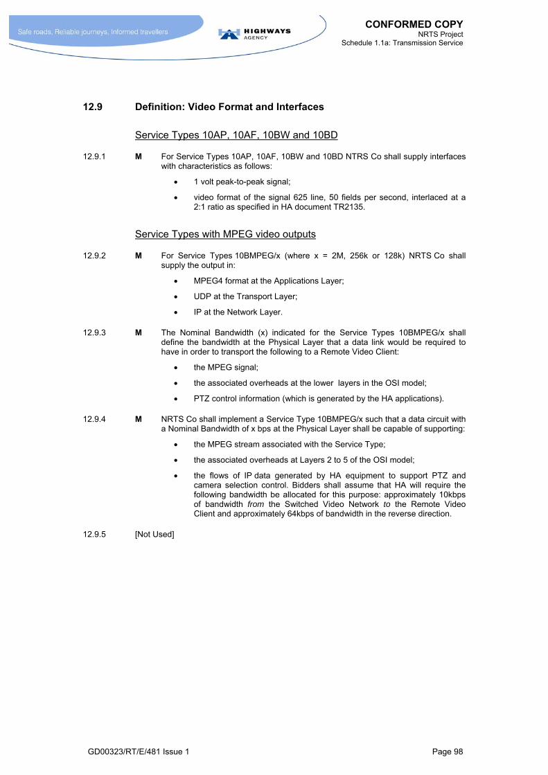
CONFORMED COPY NRTS Project
Schedule 1.1a: Transmission Service
GD00323/RT/E/481 Issue 1 Page 98
12.9 Definition: Video Format and Interfaces
Service Types 10AP, 10AF, 10BW and 10BD
12.9.1 M For Service Types 10AP, 10AF, 10BW and 10BD NTRS Co shall supply interfaces with characteristics as follows:
1 volt peak-to-peak signal;
video format of the signal 625 line, 50 fields per second, interlaced at a 2:1 ratio as specified in HA document TR2135.
Service Types with MPEG video outputs
12.9.2 M For Service Types 10BMPEG/x (where x = 2M, 256k or 128k) NRTS Co shall supply the output in:
MPEG4 format at the Applications Layer;
UDP at the Transport Layer;
IP at the Network Layer.
12.9.3 M The Nominal Bandwidth (x) indicated for the Service Types 10BMPEG/x shall define the bandwidth at the Physical Layer that a data link would be required to have in order to transport the following to a Remote Video Client:
the MPEG signal;
the associated overheads at the lower layers in the OSI model;
PTZ control information (which is generated by the HA applications).
12.9.4 M NRTS Co shall implement a Service Type 10BMPEG/x such that a data circuit with a Nominal Bandwidth of x bps at the Physical Layer shall be capable of supporting:
the MPEG stream associated with the Service Type;
the associated overheads at Layers 2 to 5 of the OSI model;
the flows of IP data generated by HA equipment to support PTZ and camera selection control. Bidders shall assume that HA will require the following bandwidth be allocated for this purpose: approximately 10kbps of bandwidth from the Switched Video Network to the Remote Video Client and approximately 64kbps of bandwidth in the reverse direction.
12.9.5 [Not Used]

CONFORMED COPY NRTS Project
Schedule 1.1a: Transmission Service
GD00323/RT/E/481 Issue 1 Page 99
Definition: Video Format and Interfaces
12.9.5.1 M At the request of the HA, NRTS Co shall issue software video decoders for use by parties designated by the HA. These software video decoders shall:
be compatible with the 10BMPEG/x Service Types;
be such that they can readily be incorporated in applications developed by other parties;
provide the capability for an external application to command the decoder to listen and/or connect to an encoded video stream from an Instance of Service Type 10MPEG/x;
provide the capability to receive and decode an incoming encoded video stream conforming to the format adopted for 10BMPEG/x Service Types;
provide the capability to render decoded video to a computer monitor from an Instance of Service Type 10MPEG/x;
provide the capability for an external application to command the decoder to stop listening for the stream and/or disconnect from the encoded video stream from an Instance of Service Type 10MPEG/x;
manage video transmission interactions with the encoder for an Instance of Service Type 10MPEG/x, such that any errors, failures or interruptions in the transmission between the encoder and decoder are handled gracefully by the decoder.
12.9.5.2 M NRTS Co shall maintain a record of all the parties to whom they have issued software decoders.
Requirement for Alternative Interfaces and Video Formats
12.9.6 [Not Used]
Full Interface Definitions
12.9.7 M NRTS Co shall offer the Interface Types identified in Annex A.1 and defined in Annex B.2.
12.9.8 M A Registered Document containing the information identified in Annex B.1 shall be fully developed by NRTS Co for Service Category 10 as part of the Service Solution Specification prior to the Get Consent to Service Solution process (Schedule 1.2 section 4.3).
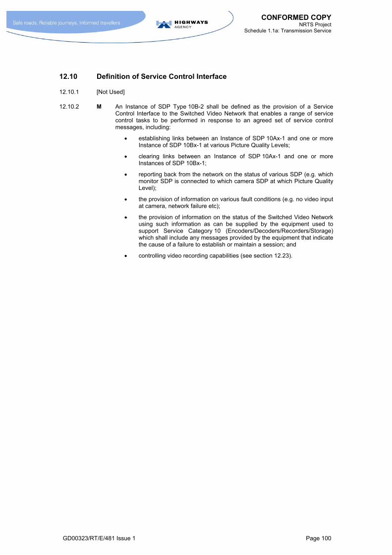
CONFORMED COPY NRTS Project
Schedule 1.1a: Transmission Service
GD00323/RT/E/481 Issue 1 Page 100
12.10 Definition of Service Control Interface
12.10.1 [Not Used]
12.10.2 M An Instance of SDP Type 10B-2 shall be defined as the provision of a Service Control Interface to the Switched Video Network that enables a range of service control tasks to be performed in response to an agreed set of service control messages, including:
establishing links between an Instance of SDP 10Ax-1 and one or more Instance of SDP 10Bx-1 at various Picture Quality Levels;
clearing links between an Instance of SDP 10Ax-1 and one or more Instances of SDP 10Bx-1;
reporting back from the network on the status of various SDP (e.g. which monitor SDP is connected to which camera SDP at which Picture Quality Level);
the provision of information on various fault conditions (e.g. no video input at camera, network failure etc);
the provision of information on the status of the Switched Video Network using such information as can be supplied by the equipment used to support Service Category 10 (Encoders/Decoders/Recorders/Storage) which shall include any messages provided by the equipment that indicate the cause of a failure to establish or maintain a session; and
controlling video recording capabilities (see section 12.23).

CONFORMED COPY NRTS Project
Schedule 1.1a: Transmission Service
GD00323/RT/E/481 Issue 1 Page 101
12.11 Requirements: Service Control Interface
12.11.1 [Not Used]
12.11.2 [Not Used]
12.11.3 [Not Used]
12.11.4 M NRTS Co shall ensure that the SCI is in a form that can be easily adopted by a wide range of CCTV equipment suppliers.
12.11.5 M NRTS Co shall only adopt the specification (or changes to the specification) for the Service Control Interface after consent has been given by the HA.
12.11.6 M The SCI shall take the form of a set of standard service control messages, together with interface definitions at the network, data link and physical layers. The SCI shall be based on the work being undertaken on developing the TVBS carried out under the M27 CCTV project5 and, specifically, NRTS Co shall:
a) Design and develop the SCI to meet the requirements of this Schedule 1.1a;
b) without prejudice to the requirements of Schedule 1.1a, design and develop the SCI to incorporate the capabilities of NRTS Co’s solution as described in the Service Solution Specification;
c) use MCH1959 Issue B as the starting point for the design and development of the SCI; and
d) be responsible for updating and managing MCH1959, which shall become a Registered Document.
12.11.7 M Within 3 months of the Execution Date, NRTS Co shall issue free of charge to the HA and potential suppliers of TV Base Station equipment (or equipment performing a broadly similar function) all of the following:
a) full details of the SCI;
b) a software package that emulates the SCI and provides a user-friendly method for suppliers to test the compatibility of their equipment with the Switched Video Network;
c) clear and comprehensive explanatory information to support (a) and (b).
12.11.8 M In pursuance of paragraph 12.11.7, NRTS Co shall offer the potential suppliers of TV Base Station equipment (or equipment performing a broadly similar function) all reasonable assistance in the development, implementation and compatibility testing of the SCI of such suppliers’ equipment.
12.11.9 M NRTS Co shall transfer ownership of any Intellectual Property Rights associated with the SCI to the HA in accordance with Clause 39.4 of the Project Agreement.
12.11.10 M NRTS Co shall provide equipment, relevant software, and facilities to enable suppliers and potential suppliers and the HA to undertake testing to establish the compatibility of TV Base Station equipment (or equipment performing a broadly similar function) with the Switched Video Network.
5 The M27 CCTV project used MCH1959 section 7.5 as starting point.

CONFORMED COPY NRTS Project
Schedule 1.1a: Transmission Service
GD00323/RT/E/481 Issue 1 Page 102
12.11.11 M NRTS Co shall regard liaison with suppliers and assistance in the use of the equipment identified in paragraph 12.11.10 during the development phase of the Service Control Interface as forming part of the supply of the Transmission Service.
12.11.12 M For the avoidance of doubt, NRTS Co shall not be eligible for support for the activity in paragraph 12.11.11 under the Consultancy Service.
12.11.13 M NRTS Co shall ensure that the set of messages at the SCI includes (amongst others) messages for the following purposes:
informing the TVBS (or other unit that supports an SCI) that there is no capacity left on the Switched Video Network to support further video sessions;
controlling video recording capabilities.
Note on Transitional Arrangements
12.11.14 [Not Used]
12.11.15 [Not Used]
12.11.16 M NRTS Co shall ensure that the Service Category 10 solution be such that it accommodates the transition:
from control by the TVC;
to control by the TVBS
without any need to modify the Service Category 10 solution other than changes to configuration data. Note: the TVCs at RCCs are to function with a subset of the standard SCI message set.
12.11.17 M NRTS Co shall be responsible for ensuring that the Service Category 10 network operates satisfactorily with either the TVBS or TVC with respect to the Service Control Interface, and the functions associated with that interface. This responsibility shall be regarded as part of NRTS Co’s responsibilities for Service Category 10 deployment and shall be included within the cost of the Base Service Charge.
12.11.18 M The Service Category 4 to Service Category 10 conversion excludes converting the PTZ circuits between the instation and roadside cameras. For this reason the TVBS will support legacy PTZ interfaces as well as an IP interface for PTZ control to new TVSSs. In other words, the TVBS will provide interfaces to support PTZ control over both of the following transmission arrangements:
Service Type 4A or 4B;
Service Category 8.
NRTS Co shall take the above into account in the design and implementation of its technical solution.

CONFORMED COPY NRTS Project
Schedule 1.1a: Transmission Service
GD00323/RT/E/481 Issue 1 Page 103
12.12 Requirements: Switching
12.12.1 M The Switched Video network shall support point-to-point and point-to-multipoint links.
12.12.2 M The Picture Quality Level shall be selectable on a session-by-session basis subject to any technical constraints imposed by the DVR equipment or identified in paragraph 12.8.6.
12.12.3 [Not Used]
12.12.4 M During a point-to-multipoint session it shall be possible to establish new links, and clear existing links at any time.
12.12.5 M The solution supplied by NRTS Co shall be such that it is possible to add and remove video outputs to a multipoint session without having to stop and restart the session.
12.12.6 M At COs, there is often a need to display a sequence of video signals from a number of different cameras on particular monitors. The task of generating such a sequence (known as an autocycle) will be performed by a TVBS, and will not be the responsibility of NRTS Co. In supporting autocycles, NRTS Co shall undertake the video switching function such that the screen does not go blank between successive images.
12.12.7 M The NRTS Co solution should be such that no break in transmission is discernible to users when a monitor is switched between different video signals. In other words, the transition between successive video images shall be such that it appears to happen instantaneously to viewers.
12.12.8 M The NRTS Co solution should be such that switching a video image at one output port causes no interference with, or degradation to, the video image at another output port.
12.13 Requirements: Picture Quality
12.13.1 M NRTS Co shall ensure that the video quality for any transmission shall equal or exceed that of the Picture Quality Level selected for that transmission, where:
“any transmission” means the transmission of a signal between any Instance of Service Type 10Ax and any Instance of Service Type 10Bx located anywhere on the NRTS Co Switched Video Network; and,
“Picture Quality Level selected” means the Picture Quality Level defined by commands sent across an Instance of the Service Control Interface (SDP10B-2) to establish the transmission; and,
the Picture Quality Levels are as specified in Table 12-4.
12.13.2 [Not Used]
CONFORMED COPY NRTS Project
Schedule 1.1a: Transmission Service
GD00323/RT/E/481 Issue 1 Page 104
12.14 Requirements: Traffic Handling Capability – General
12.14.1 [Not Used]
12.14.2 [Not Used]
12.14.3 [Not Used]
12.14.4 [Not Used]
12.14.5 M The traffic handling requirements of the NRTS Co solution for all traffic, including Service Category 10 traffic, shall be as defined by the Capacity Model see paragraphs 17.5.12 to 17.5.17.
12.15 [Not Used]
12.16 [Not Used]
12.17 [Not Used]
12.18 [Not Used]
12.19 [Not Used]
Table 12-5 [Not Used]
12.20 [Not Used]
12.21 Use of CCTV for Evidential Purposes
12.21.1 [Not Used]
12.21.2 M NRTS Co shall comply with any guidance issued by the Home Office regarding the transmission and storage of video images. Such advice shall include “Digital Imaging Procedure Version 1.0” (Home Office, Police Scientific Development Branch (PSDB) ISBN 1840 82 7343).

CONFORMED COPY NRTS Project
Schedule 1.1a: Transmission Service
GD00323/RT/E/481 Issue 1 Page 105
12.22 Performance Requirements
Picture Quality Level
12.22.1 [Not Used]
12.22.2 M NRTS Co shall undertake an assessment of video quality using MCG1111 (see paragraph 12.8.1) as part of the Get Consent to Service Solution process (Schedule 1.2 section 4.3), and on other occasions as requested by the HA.
12.22.3 M NRTS Co shall repeat MCG1111 (in the presence of an HA representative) if any element of the transmission path that affects picture quality (most notably the codecs) is changed.
12.22.4 [Not Used]
Latency
12.22.5 [Not Used]
12.22.6 [Not Used]
12.22.7 [Not Used]
12.22.8 [Not Used]
12.22.9 [Not Used]
12.22.10 M NRTS Co shall ensure that the Video Path Latency at a particular PQL meets the requirements identified in Table 12-4 and paragraph 12.22.11.
12.22.11 M The Video Path Latency shall be less than, or equal to, that stated in Table 12-4.
12.22.11.1 M The Video Path Latency shall be defined as the time lag between a change in the video image presented at the camera SDP (e.g. SDP10AP-1 or SDP10AF-1) and the same change occurring in the video image presented to the monitor SDP (e.g. SDP10BD-1, SDP10BW-1), taking into account all delays that occur between the two SDPs including:
delays associated with video multiplexing and demultiplexing;
delays associated with video encoding and decoding;
the network latency involved in the transmission of data from the video encoder to the video decoder.
Where the destination SDP is of Service Types 10BMPEG/x, then the Video Path Latency shall additionally include:
the delays associated with re-encoding
the delays associated with translating the video stream into visual image using either a hardware or software decoder of an agreed type.

CONFORMED COPY NRTS Project
Schedule 1.1a: Transmission Service
GD00323/RT/E/481 Issue 1 Page 106
Switching Time
12.22.12 M The Switching Time shall be defined as the time between Event 1 and Event 2, where these are as follows:
Event 1 – when the instruction to switch the image is sent across the SCI;
Event 2 – when the new image is supplied by the relevant Instance of Service Type 10Bx to the monitor (or equivalent device or interface).
12.22.13 M The maximum Switching Time shall be less than:
0.75 seconds for PQL1, PQL2 and PQL3;
1.2 seconds for PQL4;
1.0 second for PQL5.
12.22.14 M The maximum Switching Time requirement in paragraph 12.22.13 shall apply under all conditions including all of the following conditions:
when Event 1 occurs the required Instances of Service Type 10Ax and 10Bx are dormant (i.e. not engaged in video sessions with other Service Type Instances);
when Event 1 occurs the required Instance of Service Type 10Ax is already engaged in a video session with one or more Instances of Service Type Bx (other than the required Instance), and the required Instance of Service Type Bx is dormant;
when Event 1 occurs the required Instance of Service Type 10Ax and the required Instance of Service Type 10Bx are already engaged in video sessions with other Service Type Instances.
CONFORMED COPY NRTS Project
Schedule 1.1a: Transmission Service
GD00323/RT/E/481 Issue 1 Page 107
Testing
12.22.15 M NRTS Co shall undertake comprehensive testing of the generic Service Category 10 solution as part of the Get Consent for Service Solution process (see Schedule 1.2 section 4.3), and on other occasions as requested by the HA. Such tests shall be undertaken:
as part of the initial giving of consent by HA to the Service Category 10 solution;
when changes are made to the Service Category 10 solution.
12.22.16 M NRTS Co shall demonstrate that appropriate acceptance tests are satisfied when:
the network supplying Service Types 10Ax and 10Bx is first Provisioned in a CO area;
individual Instances of Service Type 10Ax and Service Type 10Bx (both SDP 10Bx-1 and the Control Interface SDP 10B-2) are added;
when requested by the HA – for example when HA staff are concerned about picture quality.
12.22.17 M NRTS Co shall monitor the performance of the general population of STIs in Service Category 10 throughout the life of the Contract by carrying out appropriate tests on randomly selected samples of STI. The details of the approach shall be defined as part of the Get Consent to Service Solution process (Schedule 1.2 section 4.3)
12.23 Video Recording
12.23.1 [Not Used]
12.23.2 [Not Used]
12.23.3 [Not Used]
12.23.4 [Not Used]
12.23.5 [Not Used]
12.23.6 [Not Used]
12.23.7 M NRTS Co shall supply Digital Video Recording capabilities for every Instance of Service Type 10AP.
12.23.8 M NRTS Co shall supply Digital Video Recording capabilities for every Instance of Service Type 10AF.
12.23.9 M NRTS Co shall ensure that the Digital Video Recording capabilities shall satisfy the requirements given in paragraphs 12.23.10 to 12.23.51.

CONFORMED COPY NRTS Project
Schedule 1.1a: Transmission Service
GD00323/RT/E/481 Issue 1 Page 108
Pre-Event Recording
12.23.10 M For each Instance of Service Type 10 AP or Service Type 10AF, a rolling buffer arrangement shall be provided that offers T1 minutes of recording at PQL1 for Service Type 10 AP or at PQL4 for Service Type 10AF. (This feature shall be referred to as Pre Event recording.)
12.23.11 M T1 shall be configurable by the HA from the CO. Each Instance of Service Type 10AP or Service Type 10AF shall be capable of being separately configured.
12.23.12 M Sufficient storage capacity to support Pre-Event recording shall be provided by NRTS Co such that a T1 setting of 60 minutes for all STIs can be supported.
Post-Event Recording
12.23.13 M In response to a command sent across the SCI, it shall be possible to continue recording any STI at the same picture quality as applies for the Pre-Event recording, see paragraph 12.23.10. (This feature shall be referred to as Post-Event recording.)
12.23.14 M The requirement stated in paragraph 12.23.15 to provide 3 hours Post Event storage per camera shall be understood in the sense implied by the following examples:
Example A
3 events per camera per month;
1 hour per event;
store cleared once a month;
therefore capacity required per camera = 3 x 1 hour = 3 hours.
Example B
10 events per camera per week;
0.3 hours per event;
store cleared once a week;
therefore capacity required per camera = 10 x 0.3 hour = 3 hours.
12.23.15 M NRTS Co shall provide at least 3 hours Post-Event storage capacity per camera (i.e. per Instance of ST 10 AP or ST 10 AF).
12.23.16 M The Post-Event storage capacity shall be such that it can be pooled amongst groups of at least 10 cameras. In other words, there shall be a pool of at least 30 camera-hours of storage available in any Post-Event store.
12.23.17 M NRTS Co shall provide a message across the Service Control Interface to warn CO staff that Post-Event recording has been in operation for more than T2 minutes, where T2 is configurable;
12.23.18 M NRTS Co shall cause Post-Event recording to cease T3 minutes (where T3 is configurable) after the warning information (referred to in paragraph 12.23.17) has been sent across the Service Control Interface, unless a message continue recording has been sent from the Control Office over the SCI.
12.23.19 [Not Used]
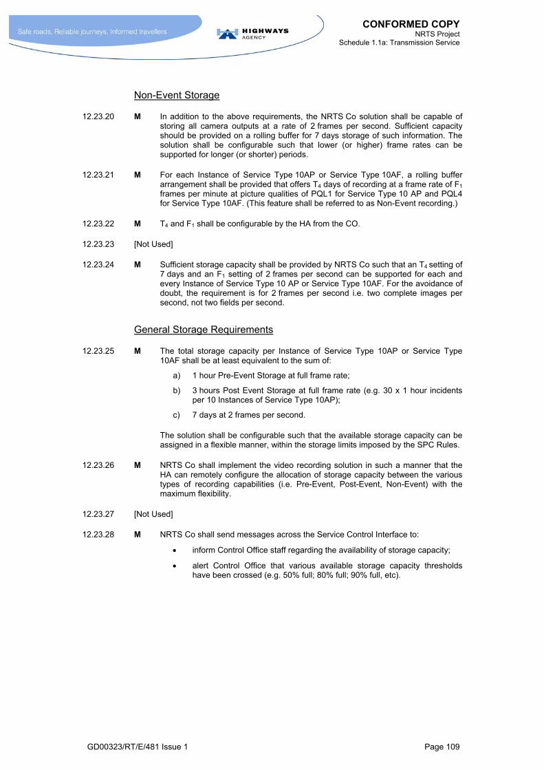
CONFORMED COPY NRTS Project
Schedule 1.1a: Transmission Service
GD00323/RT/E/481 Issue 1 Page 109
Non-Event Storage
12.23.20 M In addition to the above requirements, the NRTS Co solution shall be capable of storing all camera outputs at a rate of 2 frames per second. Sufficient capacity should be provided on a rolling buffer for 7 days storage of such information. The solution shall be configurable such that lower (or higher) frame rates can be supported for longer (or shorter) periods.
12.23.21 M For each Instance of Service Type 10AP or Service Type 10AF, a rolling buffer arrangement shall be provided that offers T4 days of recording at a frame rate of F1 frames per minute at picture qualities of PQL1 for Service Type 10 AP and PQL4 for Service Type 10AF. (This feature shall be referred to as Non-Event recording.)
12.23.22 M T4 and F1 shall be configurable by the HA from the CO.
12.23.23 [Not Used]
12.23.24 M Sufficient storage capacity shall be provided by NRTS Co such that an T4 setting of 7 days and an F1 setting of 2 frames per second can be supported for each and every Instance of Service Type 10 AP or Service Type 10AF. For the avoidance of doubt, the requirement is for 2 frames per second i.e. two complete images per second, not two fields per second.
General Storage Requirements
12.23.25 M The total storage capacity per Instance of Service Type 10AP or Service Type 10AF shall be at least equivalent to the sum of:
a) 1 hour Pre-Event Storage at full frame rate;
b) 3 hours Post Event Storage at full frame rate (e.g. 30 x 1 hour incidents per 10 Instances of Service Type 10AP);
c) 7 days at 2 frames per second.
The solution shall be configurable such that the available storage capacity can be assigned in a flexible manner, within the storage limits imposed by the SPC Rules.
12.23.26 M NRTS Co shall implement the video recording solution in such a manner that the HA can remotely configure the allocation of storage capacity between the various types of recording capabilities (i.e. Pre-Event, Post-Event, Non-Event) with the maximum flexibility.
12.23.27 [Not Used]
12.23.28 M NRTS Co shall send messages across the Service Control Interface to:
inform Control Office staff regarding the availability of storage capacity;
alert Control Office that various available storage capacity thresholds have been crossed (e.g. 50% full; 80% full; 90% full, etc).

CONFORMED COPY NRTS Project
Schedule 1.1a: Transmission Service
GD00323/RT/E/481 Issue 1 Page 110
Retrieval
12.23.29 [Not Used]
12.23.30 [Not Used]
12.23.31 M NRTS Co shall ensure that the contents of the various Local Video Stores identified in requirements 12.23.9 to 12.23.24 shall be retrievable from the Control Office or other locations (see note at the end of this paragraph 12.23.31) on the NRTS Co Switched Video Network in a user-friendly fashion. The following features shall be supported:
a) capability to retrieve by means of both:
file transfer;
video stream;
b) amount of video retrieved to be configurable, e.g. for 1 minute to entire store contents;
c) capability to download video recording stores as low priority traffic, i.e. such that downloading does not adversely affect the ability of the network to support higher priority traffic;
d) capability to select material for retrieval based on a range of criteria including:
date;
time; and
camera number;
e) access authorisation mechanisms to ensure that only designated personnel can access the video recording stores;
f) a hierarchy of access rights such that different classes have the rights:
only to download recordings;
download and delete recordings;
as above plus record images from cameras;
as above plus change configurations.
Note: The ‘other locations’ referred to in the first sentence of this paragraph will require equipment with either (a) software clients, as supplied in accordance with paragraph 12.23.31.3; or (b) the capabilities to retrieve content using an Instance of SDP10B-2 to control the Local Video Store.
12.23.31.1 M NRTS Co shall ensure that the operation of the various download and retrieval features described in paragraph 12.23.10 does not adversely affect the operation of the various recording facilities described in this section 12.23
12.23.31.2 [Not Used]
12.23.31.3 M NRTS Co shall supply software clients to enable staff at Control Offices and other locations to:
perform the various functions identified in paragraph 12.23.31. This software shall be such that it can be run from a standalone terminal or operator workstation;
transfer video information to Permanent Video Stores including both DVDs and VCRs. (Note: NRTS Co is not required to supply these Permanent Video Stores.)

CONFORMED COPY NRTS Project
Schedule 1.1a: Transmission Service
GD00323/RT/E/481 Issue 1 Page 111
Support for Web Server
12.23.32 [Not Used]
12.23.33 [Not Used]
12.23.34 M NRTS Co shall:
a) provide arrangements in each RCC to supply HA Web Servers with frames captured from Instances of Service Type 10AP and 10AF;
b) make these arrangements such that they can be controlled via the TVBS (over the Service Control Interface) to allow an HA assigned administrator to initiate, terminate connections and control the selection of cameras and the polling rate of captured frames;
c) provide arrangements to permit the configuration of this service such that administrator permissions may be restricted to appropriate staff;
d) provide arrangements to enable selected images to blocked for certain classes of users (e.g. to prevent accidents being viewed by the general public), in response to instructions sent across the Service Control Interface.
12.23.35 [Not Used]
12.23.36 M NRTS Co shall ensure that their solution is capable of sending a still video image from any Instance of Service Type 10AP at a picture quality equivalent to PQL1 or any Instance of Service Type 10AF at a picture quality equivalent to PQL4 in response to a command sent over the Service Control Interface.
12.23.37 M The technical solution shall be such that an individual Instance of Service Type 10 AP or Service Type 10AF can support frame rates of:
between 30 frame per minute and 0.2 frame per minute at a picture quality equivalent to PQL1;
The solution shall be configurable to support a range of format including QCIF, CIF, 2CIF, 4CIF.
12.23.38 [Not Used]
12.23.39 M The technical solution to meet the requirements identified in paragraphs 12.23.36 and 12.23.37 shall be dimensioned such as to support a frame rate (F2) of at least 1 frame per minute averaged over all Instance of Service Type 10AP and Service Type 10AF.
12.23.40 [Not Used]
12.23.41 [Not Used]
12.23.42 M NRTS Co shall ensure that the video images sent to the web server are sent in a format that includes a means of identifying the following attributes with each frame:
the source camera;
the time;
other features as appropriate.

CONFORMED COPY NRTS Project
Schedule 1.1a: Transmission Service
GD00323/RT/E/481 Issue 1 Page 112
Time Stamping
12.23.43 M NRTS Co shall ensure that all recorded images are time-stamped from a reliable timing source to within +/- 1 second of UTC (Universal Co-ordinated Time). This requirement applies to all of capabilities identified in paragraphs 12.23.10 to 12.23.42.
12.23.44 M NRTS Co shall ensure that means of time stamping it enables images to be archived, analysed and retrieved in a user-friendly fashion.
Network Capacity Constraints
12.23.45 [Not Used]
12.23.46 [Not Used]
12.23.47 [Not Used]
12.23.48 [Not Used]
12.23.49 [Not Used]
12.23.50 [Not Used]
12.23.51 [Not Used]
Use of Video Recording for Evidential Purposes
12.23.52 [Not Used]
Variant BAFOs
12.23.53 [Not Used]
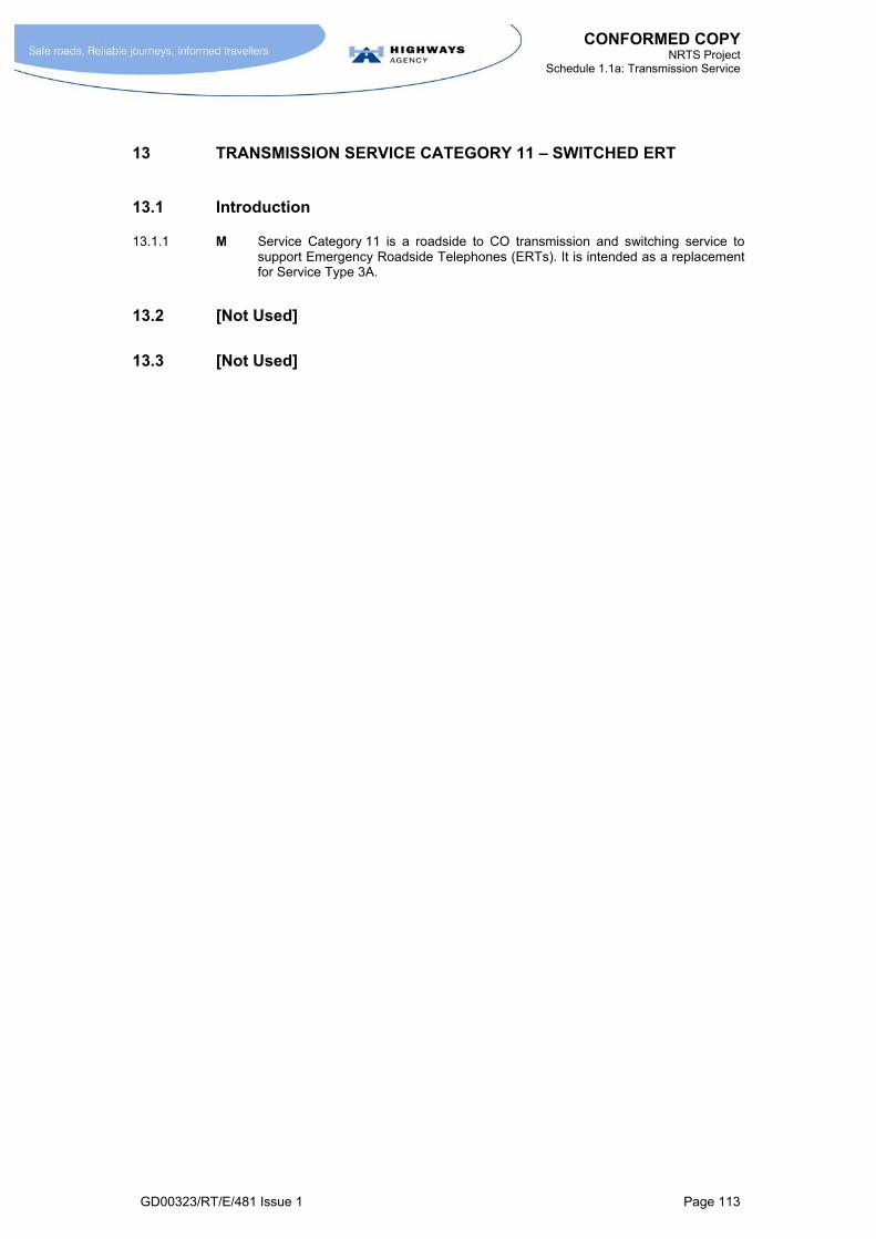
CONFORMED COPY NRTS Project
Schedule 1.1a: Transmission Service
GD00323/RT/E/481 Issue 1 Page 113
13 TRANSMISSION SERVICE CATEGORY 11 – SWITCHED ERT
13.1 Introduction
13.1.1 M Service Category 11 is a roadside to CO transmission and switching service to support Emergency Roadside Telephones (ERTs). It is intended as a replacement for Service Type 3A.
13.2 [Not Used]
13.3 [Not Used]


CONFORMED COPY NRTS Project
Schedule 1.1a: Transmission Service
GD00323/RT/E/481 Issue 1 Page 115
AggregateInterface
Roadside
NR
TS
SDP 11A-2
ERT ERT ERT ERT ERT ERT ERT
Automatic Call Distributionsystem
SDP 11A-1PCO
NRTS Network
Figure 13-1 Service Category 11


CONFORMED COPY NRTS Project
Schedule 1.1a: Transmission Service
GD00323/RT/E/481 Issue 1 Page 117
13.4 Definition: Service Type 11A
13.4.1 M An Instance of Service Type 11A shall be defined as the supply of a communications path between:
SDP 11A-2 – a connection at an ERT;
SDP 11A–1 – an Aggregate Interface at the CO (Note: this is shared with other Instances of Service Type 11A).
13.4.2 M NRTS Co shall offer the Interface Types identified in Annex A.1 and defined in Annex B.2.
13.4.3 M A Registered Document containing the information identified in Annex B.1 shall be fully developed by NRTS Co for Service Category 11 as part of the Service Solution Specification.
13.5 Performance Requirements
13.5.1 [Not Used]
13.5.2 [Not Used]
13.5.3 [Not Used]
13.5.4 [Not Used]
13.5.5 M NRTS Co shall ensure that the design and operation of their Service Category 11 solution offers performance and capabilities that are superior to those provided by the current NMCS2 arrangements for ERTs with regard to:
reliability;
traffic handling capabilities (i.e. freedom from congestion);
quality of speech path.
13.5.6 M The solution shall be fully specified by NRTS Co as part of the Get Consent to Service Solution process (Schedule 1.2 section 4.3).
13.5.7 M At the request of the HA, NRTS Co shall, using appropriate network modelling tools, demonstrate to the HA that any proposed arrangements to deliver Service Category 11 shall be capable of meeting any traffic handling requirements agreed with the HA.
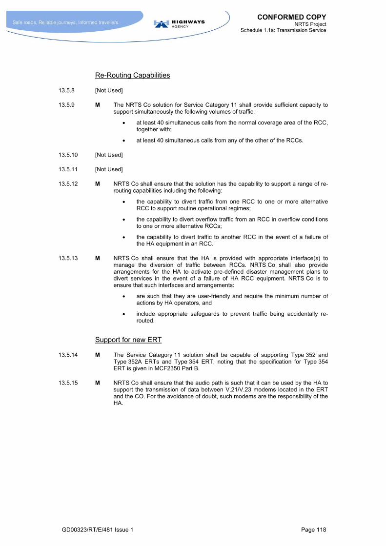
CONFORMED COPY NRTS Project
Schedule 1.1a: Transmission Service
GD00323/RT/E/481 Issue 1 Page 118
Re-Routing Capabilities
13.5.8 [Not Used]
13.5.9 M The NRTS Co solution for Service Category 11 shall provide sufficient capacity to support simultaneously the following volumes of traffic:
at least 40 simultaneous calls from the normal coverage area of the RCC, together with;
at least 40 simultaneous calls from any of the other of the RCCs.
13.5.10 [Not Used]
13.5.11 [Not Used]
13.5.12 M NRTS Co shall ensure that the solution has the capability to support a range of re-routing capabilities including the following:
the capability to divert traffic from one RCC to one or more alternative RCC to support routine operational regimes;
the capability to divert overflow traffic from an RCC in overflow conditions to one or more alternative RCCs;
the capability to divert traffic to another RCC in the event of a failure of the HA equipment in an RCC.
13.5.13 M NRTS Co shall ensure that the HA is provided with appropriate interface(s) to manage the diversion of traffic between RCCs. NRTS Co shall also provide arrangements for the HA to activate pre-defined disaster management plans to divert services in the event of a failure of HA RCC equipment. NRTS Co is to ensure that such interfaces and arrangements:
are such that they are user-friendly and require the minimum number of actions by HA operators, and
include appropriate safeguards to prevent traffic being accidentally re-routed.
Support for new ERT
13.5.14 M The Service Category 11 solution shall be capable of supporting Type 352 and Type 352A ERTs and Type 354 ERT, noting that the specification for Type 354 ERT is given in MCF2350 Part B.
13.5.15 M NRTS Co shall ensure that the audio path is such that it can be used by the HA to support the transmission of data between V.21/V.23 modems located in the ERT and the CO. For the avoidance of doubt, such modems are the responsibility of the HA.

CONFORMED COPY NRTS Project
Schedule 1.1a: Transmission Service
GD00323/RT/E/481 Issue 1 Page 119
13.6 Aggregate Interface Requirements
Aggregate Interface Requirements for ICCS
13.6.1 [Not Used]
13.6.2 M NRTS Co shall agree the Aggregate Interface with the ICCS supplier and implement the Aggregate Interface to ensure successful operation with the Integrated Communications Control System (ICCS). This Aggregate Interface shall be defined as part of the Get Consent to Service Solution process (Schedule 1.2 section 4.3).
13.6.3 M NRTS Co shall be responsible for ensuring the integration of the ICCS system and the NRTS Co network results in reliable end-to-end operation of the overall ERT system.
13.6.4 M NRTS Co shall implement the Aggregate Interface at the CO (SDP 11A-1) such that it supports voice and signalling traffic, using a widely recognised standard. The features offered shall include the capability to support Calling Line Identification (CLI).
13.6.5 M The Service Category 11 solution shall perform traffic concentration such that the Aggregate Interface presented to the ICCS requires no more than two E1 circuits (or other agreed equivalent) to support traffic from roadside ERT within the CO Home Area.
Aggregate Interface Requirements for full functionality call centre
13.6.6 [Not Used]
13.6.7 [Not Used]
13.6.8 M NRTS Co shall ensure that the capabilities of the Aggregate Interface shall be such that it permits the HA to implement a call centre that offers a range of capabilities is at least as great as those offered by the current NMCS2 arrangements.
13.6.9 M The Aggregate Interface shall support a wide range of standards, including QSIG and standards appropriate to Voice over IP such as H.323 or SIP.
13.6.10 M NRTS Co shall ensure that, amongst the capabilities of the signalling interface identified in paragraph 13.6.8, the following capability is included: the ability to pass Calling Line Identification information to the HA call centre from parties whose call attempts are being blocked due to network congestion.
13.7 Variant of Potential Interest to the HA
13.7.1 [Not Used]
13.7.2 [Not Used]
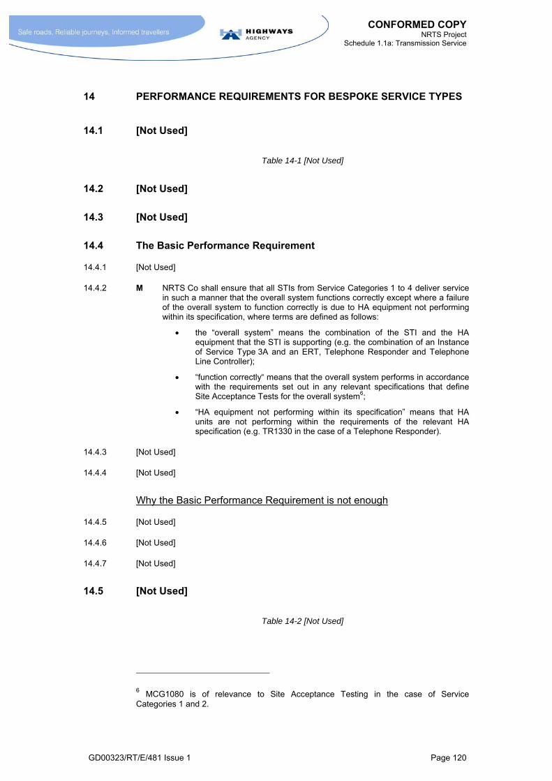
CONFORMED COPY NRTS Project
Schedule 1.1a: Transmission Service
GD00323/RT/E/481 Issue 1 Page 120
14 PERFORMANCE REQUIREMENTS FOR BESPOKE SERVICE TYPES
14.1 [Not Used]
Table 14-1 [Not Used]
14.2 [Not Used]
14.3 [Not Used]
14.4 The Basic Performance Requirement
14.4.1 [Not Used]
14.4.2 M NRTS Co shall ensure that all STIs from Service Categories 1 to 4 deliver service in such a manner that the overall system functions correctly except where a failure of the overall system to function correctly is due to HA equipment not performing within its specification, where terms are defined as follows:
the “overall system” means the combination of the STI and the HA equipment that the STI is supporting (e.g. the combination of an Instance of Service Type 3A and an ERT, Telephone Responder and Telephone Line Controller);
“function correctly“ means that the overall system performs in accordance with the requirements set out in any relevant specifications that define Site Acceptance Tests for the overall system6;
“HA equipment not performing within its specification” means that HA units are not performing within the requirements of the relevant HA specification (e.g. TR1330 in the case of a Telephone Responder).
14.4.3 [Not Used]
14.4.4 [Not Used]
Why the Basic Performance Requirement is not enough
14.4.5 [Not Used]
14.4.6 [Not Used]
14.4.7 [Not Used]
14.5 [Not Used]
Table 14-2 [Not Used]
6 MCG1080 is of relevance to Site Acceptance Testing in the case of Service Categories 1 and 2.
CONFORMED COPY NRTS Project
Schedule 1.1a: Transmission Service
GD00323/RT/E/481 Issue 1 Page 121
14.6 Additional Performance Requirements
14.6.1 [Not Used]
14.6.2 [Not Used]
14.6.3 M NRTS Co shall carry out the following tests when installing cable:
MCG1022 for armoured cables;
MCG1055 for optical fibre cables;
MCG1099 for non-armoured cables.
14.6.4 [Not Used]
14.7 Testing Methodology
14.7.1 M NRTS Co shall develop Registered Documents that define the procedures to be followed in relation to each of the following items. These documents shall be completed within 6 months of the Execution Date or before Service Take-On in the first area, whichever is the earlier:
a) Acceptance Tests for new infrastructure: these shall define the procedures to be conducted when new physical infrastructure is installed by NRTS Co prior to HA equipment being connected to any SDP associated with the new provision;
b) Acceptance Tests for new STIs on existing infrastructure: these shall define the procedures to be conducted when a new connection is made to existing infrastructure, for example when a new STI is added to a pre-existing multidrop circuit;
c) In-Service Tests (non-intrusive): these shall define the tests and procedures to be carried out on STIs whilst in operation. Typically such tests are undertaken to investigate a suspected fault, or as part of on-going monitoring.
d) In-Service Tests (intrusive): these shall define the tests and procedures that shall be carried out to investigate a suspected fault that require the disconnection of HA equipment.
14.7.2 M The In-Service Test methodologies shall include the use of COBS fault logs (including the LIMO log) via Halogen, or other arrangements offering an equivalent capability, or the use of equivalent data from successor system should these systems be replaced. This methodology shall be used to monitor “retries” or other attributes that might indicate the quality of the transmission links. Such an approach shall be used to monitor performance trends with the transmission links that support Service Types 1A, 2A, 2B, 2C, 3A.
14.7.2.1 M In relation to this requirement, any changes to HA interfaces which have a material impact on NRTS Co shall be treated as described in Annex B.1.2.24 Schedule 1.2.
14.7.3 M The In-Service Test methodologies shall also include the use of portable oscilloscopes and spectrum analysers with associated software to analyse performance of STIs.
14.7.4 M NRTS Co shall provide arrangements that allow fault logging and analysis of the ERT systems to continue even when the COBS link is unavailable. NRTS Co shall provide this through interfacing to the existing IPLU supervision, if available.
14.7.5 [Not Used]

CONFORMED COPY NRTS Project
Schedule 1.1a: Transmission Service
GD00323/RT/E/481 Issue 1 Page 122
14.8 [Not Used]
14.9 Next Steps
14.9.1 [Not Used]
14.9.2 M The Performance Requirements for all Service Types in Service Categories 1, 2 and 3 and for Service Type 4A and Service Type 4B shall be as defined in MCG1058 with the following changes:
Test 1 and Test 6 are not Mandatory Requirements;
In Test 2, 3, 5 and 7 the tests shall be carried out between the SDP at the CO and the SDP at the intermediate device (e.g. the Standard Transponder, MIDAS Transponder, Telephone Responder, TVC), rather than between the SDP at the CO and the end of the transmission line. During such tests the end of the transmission line shall remain correctly terminated;
All the SDPs using the same shared circuit shall be connected and terminated in an agreed manner;
In undertaking these tests, the Downstream SDP shall be connected to test equipment that presents the same impedance as would be presented by the HA device normally connected to that SDP;
The mask for group delay performance used in Test 3 shall be that stated in the ITU specification M1020 rather than that stated in MCG1058.
14.9.3 [Not Used]
14.9.4 [Not Used]
14.9.5 M NRTS Co shall undertake a national survey of STIs following a programme to be completed within two years of the Execution Date. This national survey will involve the following elements:
a) a simple In-Service test on every SDP to SDP link for every STI in Service Categories 1, 2 and 3 (see paragraph 14.9.7 below) and every SDP to SDP link for every STI used for the PTZ control of CCTV cameras (including all Instances of Service Type 4A and Service Type 4B);
b) full tests against the performance requirements used for the acceptance tests for any STI that fails to satisfy the requirements of the In-Service test;
c) an investigation to determine the cause for each case of non-compliance with the performance requirements;
d) the production of a report to the HA containing the results of (a) to (c) above.
14.9.6 M NRTS Co shall be responsible for undertaking any remedial action required to ensure that Service Types comply with their performance requirements.
14.9.6.1 M In relation to paragraph 14.9.6 an exception shall be made where the circuit exceeds the length specified in HA standards. In such cases, NRTS Co shall be responsible for ensuring such STIs operate at the standard of performance appropriate to that length.
14.9.7 [Not Used]
14.9.8 M NRTS Co shall ensure that the national survey of STIs (described in paragraph 14.9.5) is co-ordinated with NRTS Co’s programme of routine maintenance.

CONFORMED COPY NRTS Project
Schedule 1.1a: Transmission Service
GD00323/RT/E/481 Issue 1 Page 123
14.9.9 [Not Used]
14.9.10 [Not Used]
14.9.11 M For the avoidance of doubt, NRTS Co shall rectify any cases where the video paths (Service Type 4C and 4E) for Service Category 4 installations are exhibiting sub-standard performance. The performance requirements shall be based upon the requirements in MCE2015 section 7.4.
14.9.12 [Not Used]
14.10 [Not Used]
CONFORMED COPY NRTS Project
Schedule 1.1a: Transmission Service
GD00323/RT/E/481 Issue 1 Page 124
15 GENERAL TRANSMISSION SERVICE REQUIREMENTS
15.1 [Not Used]
15.2 Scope of Supply
15.2.1 [Not Used]
15.2.2 [Not Used]
15.2.3 M When supplying a Service Type Instance, unless stated otherwise, NRTS Co shall be responsible for all equipment necessary to deliver that Service Type Instance. This shall include:
the transmission system (e.g. optical fibre or coaxial cable system);
transmission equipment (e.g. amplifiers, multiplexers, optical line systems, carrier and mini-carrier systems);
radio transmission equipment (and associated radio licences);
all switching and routing equipment (e.g. Packet Switched Exchanges, IP routers)
video Matrix Switches (or alternative equipment offering this functionality);
any equipment in Transmission Stations used to deliver the Service Type Instance; and
appropriate interfaces to support the connection of HA equipment.
15.2.4 M When supplying a Service Type Instance, NRTS Co shall be responsible for all telecommunications services supplied by Public Telecommunications Operators (PTOs) necessary to deliver that Service Type Instance including:
analogue and digital circuits leased from PTOs;
IP services leased from PTOs or IP service providers;
public radio data network services;
PSTN and ISDN services leased from PTOs;
cellular radio services; and,
other services leased from PTOs, or other parties providing such services.
15.2.5 [Not Used]
15.2.6 M NRTS Co shall be responsible for all sites, buildings (including Transmission Stations), enclosures, cabinets, housing, etc, required for the delivery of the Transmission Service unless agreed otherwise with the HA or described otherwise in Schedule 1.3, Annex A - Table of Responsibilities.
15.2.7 [Not Used]
15.2.8 [Not Used]
15.2.9 [Not Used]

CONFORMED COPY NRTS Project
Schedule 1.1a: Transmission Service
GD00323/RT/E/481 Issue 1 Page 125
15.3 Service Solution Specifications
15.3.1 [Not Used]
15.3.2 M NRTS Co shall in accordance with the Get Consent to Service Solution process (Schedule 1.2 section 4.3) develop a Service Solution Specification covering every Service Type, and the Base Network as a whole.
15.3.3 [Not Used]
15.3.4 [Not Used]
15.3.5 [Not Used]
15.3.6 [Not Used]
15.3.7 [Not Used]
15.3.8 [Not Used]
15.3.9 M In accordance with the requirements identified in Schedule 1.2 paragraph 4.3.3.11, NRTS Co shall maintain a set of Solution Service Specifications for each Service Type that contains:
an overview of the Service Type;
a definition of the Service Type and the outputs delivered;
performance requirements;
additional requirements;
overview of the solution;
mandatory features of the solution;
acceptance test procedures; and,
monitoring procedures.
15.3.10 M NRTS Co shall implement and operate all Service Type Instances in accordance with any requirements expressed in the relevant Service Solution Specifications.
15.4 Critical Design Rules
15.4.1 [Not Used]
15.4.2 [Not Used]
15.4.3 M NRTS Co shall implement and operate Service Types in Service Categories 1 to 4 in accordance with the Critical Design Rules listed in Annex F.
15.4.4 [Not Used]
15.4.5 [Not Used]

CONFORMED COPY NRTS Project
Schedule 1.1a: Transmission Service
GD00323/RT/E/481 Issue 1 Page 126
15.5 Permanent Test Network and Emulators
15.5.1 [Not Used]
Permanent Test Network
15.5.2 M NRTS Co shall, at its own premises, provide a Permanent Test Network. The Permanent Test Network shall be designed to facilitate:
the testing for Service Solution Certification of the core network design and of each Service Type, including (as they arise) any new Service Types;
the testing of HA applications by HA personnel or parties designated by the HA, both during application development and for conformance testing;
the investigation of fault and performance issues with the NRTS Co Transmission Service.
15.5.3 M NRTS Co shall, given five Business Days notice, make this facility available to the HA or parties designated by the HA for the purpose of testing HA applications.
15.5.4 M The Permanent Test Network shall replicate fully the NRTS Co Transmission Service solution. In other words, it shall:
a) include all the types of hardware included in the Transmission Service solution for both the core network and for each Service Type;
b) incorporate all the representative features of the topology (e.g. rings and spurs) of the NRTS Co solution;
c) incorporate all traffic management, prioritisation, rate policing and rate shaping features of NRTS Co IP Network solution;
d) include facilities for simulating the operation of the network under various traffic conditions including heavy traffic loading;
e) incorporate all the features required to support Service Category 10, including all the Service Types and the Service Control Interface;
f) incorporate all service restoration features and any other features that influence the convergence time of the NRTS Co solution;
g) be such that any features of NRTS Co Transmission Service solution that might effect the performance of HA applications (both current and under development) can be assessed. This include (but not be limited to) features such as:
h) bandwidth constraints;
i) behaviour associated with the performance of the network under load and the operation of any prioritisation features;
j) latency;
k) service restoration time (including convergence time).
CONFORMED COPY NRTS Project
Schedule 1.1a: Transmission Service
GD00323/RT/E/481 Issue 1 Page 127
Emulators
15.5.5 M NRTS Co shall hold and, when requested, make available to the HA and parties designated by the HA, transportable units (Emulators) that simulate the performance and behaviour of the NRTS Co Service Types. NRTS Co shall hold Emulators for each of the Service Types that NRTS Co might reasonably be expected to supply. Emulators shall be suitable for a variety of purposes including the following:
development and testing of applications and systems by HA suppliers;
certification testing by the HA of equipment from suppliers.
15.5.6 M Further to the requirements of paragraph 15.5.5, NRTS Co shall ensure that the specific requirements in Table 15-1 are satisfied for the Emulators required for each Service Category.
15.5.7 [Not Used]
Access to the NRTS Co Network
15.5.8 M NRTS Co shall provide arrangements on the main network used to supply the Transmission Service to enable the HA or parties designated by the HA to use the network to test HA applications in a manner that does not interfere with the supply of operational services over the network.
NRTS Co’s Additional Responsibilities
15.5.9 M NRTS Co shall, in a timely manner, update the Permanent Test Network and the Emulators to reflect changes made, or proposed to be made, to the NRTS Co Transmission Service solution (including the core network and the Service Types).
15.5.10 M NRTS Co shall provide clear and comprehensive documentation to enable the HA and parties designated by the HA to:
understand the operation of, and make use of the Emulators referred to in paragraph 15.5.5 and 15.5.6, without requiring additional support from NRTS Co;
understand the operation of, and make use of (with the assistance of NRTS Co), the Permanent Test Network referred to in paragraphs 15.5.2 to 15.5.4.
15.5.11 [Not Used]
15.5.12 M For the avoidance of doubt, the following cannot be charged for under the Consultancy Service and are regarded as forming part of the supply of the Transmission Service and fall within the scope of the Base Service Charge:
the requirements to provide, make available for use, update and document the Permanent Test Network (described in paragraphs 15.5.2 to 15.5.4) and Emulators (described in paragraphs 15.5.5 and 15.5.6);
the requirement identified in paragraph 12.11.11.

CONFORMED COPY NRTS Project
Schedule 1.1a: Transmission Service
GD00323/RT/E/481 Issue 1 Page 128
Requirement Identity
Title Service Categories
Description (part of Mandatory Requirement) Quantity
(a) Bespoke Services Emulator
1 to 3 (except 2B) and Service
Type 4A and 4B.
A unit that emulates the characteristics of the network from the SDP located at the Standard Transponder/MIDAS Transponder/Telephone Responder/ TVT etc to the SDP located the CO. The unit simulates the characteristics of the roadside network as well as any attributes of the core network that might affect application performance (e.g. delay).
Three
(b) Service Type 2B Emulator
Service Type 2B A unit that emulates the characteristics of the network from the SDP located on the RS485 port of the MIDAS Transponder to the SDP at the CO. The unit simulates the characteristics of the of the core network that might affect application performance (e.g. delay).
Two
(c) X.25 Network Emulator
5 A unit that emulates the X.25 Network and includes elements such as a Packet Switch Exchange and the equipment associated with Service Type 5A and 5B.
Two
(d) Service Category 8 Emulator
8 A transportable unit that emulates the IP Network and has the following attributes:
uses the same SDP interface equipment and edge devices (i.e. switches/routers etc) as used
in the NRTS Co IP Network;
simulates the IP Network in relation to rate shaping, rate policing etc;
simulates the performance attributes of the NRTS Co network e.g. in relation to latency;
simulates the traffic management and prioritisation features of the IP Network and includes
capability to handle IP packets that are Diffserv marked prior to the point of ingress;
possesses traffic generating capabilities so that the performance of the various Service Types
can be recreated under a range of network conditions; and
be such that HA application developers can test the operation of HA applications on the
IP network.
Three

CONFORMED COPY NRTS Project
Schedule 1.1a: Transmission Service
GD00323/RT/E/481 Issue 1 Page 129
Requirement Identity
Title Service Categories
Description (part of Mandatory Requirement) Quantity
(e) Service Category 9 Emulator
9 A transportable unit that emulates the end-to-end performance of Service Category 9 Service Types and has the following attributes:
uses the same SDP interface equipment and edge devices (e.g. multiplexers) as the
NRTS Co Transmission Service solution;
offers the same performance characteristics (e.g. bit latency) as likely to be encountered on
the NRTS Co Transmission Service solution.
One
(f) Service Category 10 Emulator (video path)
10 A transportable unit that emulates the video transmission path between camera output and monitor and has the following attributes:
uses the same video muliplexers and codecs as the NRTS Co Transmission service solution;
offers equivalent end-to-end performance characteristics, including a similar end-to-end
latency;
has the capability of emulating the output of 10BMPEG/x services.
Three
(g) Service Category 10 SCI Emulator
10 A unit (or software package) that enables the operation of a TVBS or HAVCI to be assessed in relation to the correct receipt, transmission and interpretation of messages across the Service Control Interface.
Three
(h) “Demonstrator Interface” for software decoder
10 Software to enable the various functions supported by the MPEG 4 software decoder to be demonstrated. When installed on a PC this software will enable all the functions associated with the software decoder to be demonstrated. These functions include, but are not limited to:
the ability to set-up and clear sessions with the originating MPEG4 encoder;
the ability to view the image.
The combination of the Demonstrator Interface and the software decoder shall be equivalent to a Video Client with respect to the above attributes.
Five
Table 15-1 Emulator Requirements for each Service Category
CONFORMED COPY NRTS Project
Schedule 1.1a: Transmission Service
GD00323/RT/E/481 Issue 1 Page 130
15.6 Application Guidelines
15.6.1 [Not Used]
15.6.2 [Not Used]
15.7 Service Delivery Points: Physical Locations
SDP Definitions and Physical Implementation Diagrams
15.7.1 [Not Used]
15.7.2 [Not Used]
15.7.3 M Prior to the Actual Service Start Date for Transmission Service, in accordance with the Get Consent to Service Solution process (Schedule 1.2 section 4.3), NRTS Co shall produce:
SDP Definitions, showing the precise interface connections within the cabinet or enclosure housing the SDP (similar in scope to those given for Annex B);
Physical Implementation Diagrams, showing the generic location at roadside of the cabinet or enclosure housing the SDP (similar in scope to those shown in Annex D).
Actual SDP Location
15.7.4 [Not Used]
SDP Rules
15.7.5 [Not Used]
15.7.6 M The guiding principles for determining the location of the roadside SDP for Bespoke Service Types shall follow the rules defined in Annex C.
CONFORMED COPY NRTS Project
Schedule 1.1a: Transmission Service
GD00323/RT/E/481 Issue 1 Page 131
Presentation of Service Delivery Points
15.7.7 M In accordance with the requirements identified in the Identification and Labelling constraint (Schedule 1.3 section 2.12), NRTS Co shall be responsible for ensuring that all interfaces between the NRTS network and equipment belonging to HA or third parties designated by the HA are:
clearly labelled;
properly environmentally protected;
easily accessible.
15.7.8 [Not Used]
15.7.9 M Where NRTS Co is delivering a Service Type Instance using pre-existing equipment7, and where an SDP in the CO is difficult to access, NRTS Co shall create an easily accessible patch panel to permit maintenance and testing. NRTS Co shall have its proposals for such changes approved by the HA prior to carrying them out.
15.7.10 M NRTS Co shall also comply with the requirements relating to the labelling of SDPs given in the Identification and Labelling constraint (Schedule 1.3 section 2.12).
15.8 Additional Service Delivery Points at Transmission Stations
15.8.1 [Not Used]
15.8.2 M If requested, NRTS Co shall supply Service Type Instances with the SDPs that would normally be located in COs, located in Transmission Stations instead. NRTS Co shall supply such Service Type Instances on the same terms, and to the same requirements, as would apply if those SDPs were to be located (as normal) in the CO.
7 Pre-existing equipment shall be interpreted as equipment that was used for supply of the service by the HA before the Execution Date.
CONFORMED COPY NRTS Project
Schedule 1.1a: Transmission Service
GD00323/RT/E/481 Issue 1 Page 132
15.9 General Network Management Requirements
15.9.1 M NRTS Co shall employ appropriate arrangements for network management, for all Service Types supplied (both Bespoke and Generic Service Types). This shall include such functions as:
Fault Management;
Configuration Management;
Performance Management;
Security Management;
Address Management.
15.9.2 [Not Used]
15.9.3 [Not Used]
15.10 Fault Management
General Obligations
15.10.1 M NRTS Co shall be responsible for the monitoring of all Service Type Instances and for immediately notifying HA when a fault affecting service delivery occurs.
15.10.2 [Not Used]
Special Considerations for Service Categories 1 to 3
15.10.3 [Not Used]
15.10.4 [Not Used]
15.10.5 [Not Used]
15.10.6 [Not Used]
15.10.7 [Not Used]
15.10.8 [Not Used]
15.10.9 M NRTS Co shall define classes of symptoms displayed by the COBS data that indicate that there is a possibility that a fault is attributable to the NRTS Co network. NRTS Co shall seek the consent of the HA, in accordance with the Develop Registered Document process (see Schedule 1.2 section 4.2), before such definitions are used in operational systems. NRTS Co shall not make changes to these definitions without the prior approval of the HA.
15.10.10 [Not Used]
15.10.11 M NRTS Co shall be responsible for performing the analysis of COBS data to determine whether the conditions described in paragraph 15.10.9 have occurred.
15.10.12 [Not Used]

CONFORMED COPY NRTS Project
Schedule 1.1a: Transmission Service
GD00323/RT/E/481 Issue 1 Page 133
15.10.13 M NRTS Co shall be responsible for:
a) any modifications required to the HALOGEN system, where these modifications are necessary to support the requirements of NRTS Co; and
b) for the provision of suitable interfaces and data links between HALOGEN and the NRTS Co fault management system.
15.10.14 M In relation to this requirement, any changes to HA interfaces which have a material impact on NRTS Co shall be treated as described in Annex B.1.2.24 Schedule 1.2.
15.10.15 M Failure of the COBS system or HALOGEN shall not relieve NRTS Co of any of its responsibilities for detecting, reporting, analysing and responding to faults. The Service Credit Regime (Schedule 27) shall operate in the same fashion, irrespective of any failures in HA equipment and systems, including COBS and HALOGEN.
15.10.16 [Not Used]
15.10.17 [Not Used]
Service Categories 4, 5, 6 and 7
15.10.18 [Not Used]
15.10.19 [Not Used]
15.10.20 [Not Used]
15.10.21 [Not Used]
15.10.22 M NRTS Co shall continuously monitor the integrity of Service Type Instances in Service Category 6 except where the technical solution for service delivery is such that the provision of this capability might reasonably be regarded as impractical, or representing poor value-for-money.
15.10.23 [Not Used]
15.10.24 M NRTS Co shall act promptly in response to any fault reports from PTOs. Where the PTO provides facilities to inform users of current or future service outages, NRTS Co shall make full use of such facilities.
15.10.25 M NRTS Co shall:
promptly inform PTOs of any faults that are reported by the HA or parties designated by the HA or any faults that are detected by NRTS Co;
track progress of rectification activities by PTOs;
be proactive in ensuring that PTOs meet their commitments with regard to restoring service.
15.10.26 M NRTS Co shall immediately inform the HA, where the delivery of STIs in Service Category 7 is affected by failures in the service provided by Public Telecommunications Operators.

CONFORMED COPY NRTS Project
Schedule 1.1a: Transmission Service
GD00323/RT/E/481 Issue 1 Page 134
Service Categories 8 to 11
15.10.27 M In deploying Service Categories 8 to 11, NRTS Co shall provide systems that are capable of end-to-end fault monitoring of Service Type Instances.
15.10.28 [Not Used]
15.11 Performance Management
Capacity Management
15.11.1 M NRTS Co shall be responsible for managing the network in such a way that the Performance Requirements for the various Service Types are met.
15.11.2 [Not Used]
15.11.3 M On a monthly basis, NRTS Co shall supply the HA with data that indicates the degree to which the available network capacity is being utilised. NRTS Co shall also provide the HA with forecasts showing when and where network capacity is likely to become saturated. Prior to Build Completion Date, NRTS Co shall supply such data as existing equipment is capable of supporting.
Fault Reporting
15.11.4 M NRTS Co shall supply the HA with the following data on a monthly basis for each Service Type, for each CO area and all CO areas in aggregate:
Number of faults that affected delivery of Instances of the Service Type. These faults should be grouped by:
number of Service Type Instances affected;
nature of fault;
attendance times for faults that affected the delivery of Instances of the Service Type;
fault repair times for faults that affected the delivery of Instances of the Service Type8.
Number of faults that did not affect service delivery. These faults shall be grouped by:
degree to which the Resilience of the network was reduced by the occurrence of the fault;
nature of fault.
Various Performance Requirements that are capable of being monitored on a routine basis (e.g. Packet Loss on the IP Network).
A calculation of Availability in accordance with the requirements described in section 16.
8 These are collected for purpose of report only - they do not form part of the payment system.
CONFORMED COPY NRTS Project
Schedule 1.1a: Transmission Service
GD00323/RT/E/481 Issue 1 Page 135
Reporting Systems
15.11.5 M The NRTS Co system for storing, calculating and accessing fault and availability information shall provide at least the same level of detail and transparency as provided by the HA’s NOMAD Fault Logging system for reporting the performance of RMC maintained devices.
15.11.6 [Not Used]
15.11.7 M NRTS Co shall also provide a system for storing, analysing and accessing information on:
the performance of NRTS Co Service Types against those Performance Requirements that are capable of being monitored on a continuous basis or through routine sampling. This shall include, but not be limited to:
Service Category 5: (a) Link Availability (b) Link Utilisation (or alternative measurements agreed before the Execution Date);
Service Category 8: (a) Packet Latency (b) Goodput Ratio (c) Packet Loss;
traffic volumes and the level of capacity utilisation. This shall include such data for the:
IP Network (Service Category 8);
Switched Video Network (Service Category 10);
Switched ERT network (Service Category 11);
other networks, where practicable.
15.11.8 M Performance information shall be made available by NRTS Co to the HA in all of the following forms:
printed reports;
Web Type interface;
files in a commonly used format (e.g. Microsoft Excel).
15.11.9 M NRTS Co shall provide the HA with various search and filter tools for the analysis of performance information, and the graphical presentation of trend data.
15.11.10 M NRTS Co shall maintain historical data on availability, faults, performance, traffic, and capacity utilisation over the entire Contract Term. This shall include maintaining records relating to symptoms indicative of faults. (For example, if NRTS Co were to use SUST log data in the COBS system for fault detection, records based on such data should be maintained over the Contract Term.) NRTS Co shall undertake trend analysis to provide information on the underlying reliability of the various network elements, and how this is changing with time. NRTS Co shall respond to any requests that the HA make via the Manage Contract process (Schedule 1.2 section 2.2) for the analysis of data on historical trends.
15.11.11 M NRTS Co shall also comply with the requirement in Schedule 1.2 section B.1.2.14.
CONFORMED COPY NRTS Project
Schedule 1.1a: Transmission Service
GD00323/RT/E/481 Issue 1 Page 136
COBS Retry
15.11.12 M NRTS Co shall monitor retries as a percentage (%) of transmissions (using the COBS LIMO Log, or its equivalent) as a method of determining the performance of STIs. NRTS Co shall describe the details of its approach to monitoring retries in the Registered Document that describes NRTS Co’s solution for fault and performance management (as defined in Annex B of Schedule 1.2 and section 5.4 of Schedule 1.2, respectively).
15.11.13 M [Not used]
15.11.14 M By the Build Completion Date NRTS Co shall have in place an arrangement to continuously monitor and analyse the level of retries for every HA device for which this information is made available through HALOGEN (or equivalent system). Unless NRTS Co can demonstrate that the cause lies outside the NRTS Transmission Service, NRTS Co shall investigate and rectify any cases where:
for a particular HA device the level of retries as a percentage (%) of the number of transmissions exceeds an agreed benchmark level (where the benchmark level shall be agreed between the HA and NRTS Co and shall correspond to the level exhibited by an STI whose transmission characteristics are on the limits of acceptable transmission performance with respect to the requirements defined in section 14);
the level of retries as a percentage (%) of transmissions is showing an increasing trend with the passage of time.
15.11.15 M In relation to paragraph 15.11.14, NRTS Co shall continuously improve its approach as both more information about retries becomes available to NRTS Co and NRTS Co becomes more experienced in its analysis. To support this requirement, the HA shall make reasonable endeavours to furnish NRTS Co with information about non-transmission related causes of retries. Any changes to NRTS Co’s methods for monitoring and analysis shall be agreed with the HA before the change is implemented.
15.11.16 M For any cases identified as requiring investigation and rectification, as defined in paragraph 15.11.14:
a) within 10 Business Days (or within 3 months for the first 12 months after the Build Completion Date) of identification NRTS Co shall:
conduct an initial investigation (including site visits, where relevant) to determine the cause;
rectify the problem (to the extent that this is reasonably practicable within this period of time);
submit a report to the HA describing the investigation and the actions taken, and providing a plan for any further investigations and actions required to rectify the fault.
b) where NRTS Co, acting reasonably, found that it was not possible to rectify the fault as part of the activities identified in paragraph 15.11.16 a), then NRTS Co shall endeavour to rectify the fault within the shortest period of time that is reasonably practicable, in accordance with a plan agreed with the HA.

CONFORMED COPY NRTS Project
Schedule 1.1a: Transmission Service
GD00323/RT/E/481 Issue 1 Page 137
15.11.17 M At the earliest opportunity and by not later than the Build Completion Date, NRTS Co shall make available to the HA information that includes the following:
an analysis of data on retries; and
a list of cases for which investigation and rectification actions are in progress, together with a brief description of the actions being undertaken and the timescale for rectification,
where such information shall be updated on a continuous basis and presented in the forms identified in paragraph 15.11.8, together with a summary monthly report)
15.11.18 M Any reference to COBS in paragraphs 15.11.12 to 15.11.17 shall also be regarded as a reference to systems serving an equivalent purpose for Service Categories 1 to 4, where such arrangements provide data that is available through HALOGEN or any HA systems that replace HALOGEN. This shall include arrangements for monitoring the performance of Service Category 4.
15.11.19 M In relation to paragraph 15.11.18, any changes to HA systems which have a material impact on NRTS Co shall be treated as described in Annex B.1.2.24 Schedule 1.2. The baseline state against which changes shall be assessed will be a system that can support the requirements of paragraph 15.11.14 for Service Categories 1 and 2.
15.12 Security Management
15.12.1 [Not Used]
15.12.2 [Not Used]
15.12.3 [Not Used]
15.12.4 [Not Used]
15.12.5 [Not Used]
15.12.6 [Not Used]

CONFORMED COPY NRTS Project
Schedule 1.1a: Transmission Service
GD00323/RT/E/481 Issue 1 Page 138
15.13 Addressing and Location Service Requirements
15.13.1 M NRTS Co shall develop and maintain suitable arrangements for the management of location and address information for all Service Types, including Bespoke Service Types.
15.13.2 M In developing new addressing arrangements NRTS Co shall ensure that the addressing schemes are:
scalable, i.e. they take into account the potential development of demand during and after the Contract Term;
efficient, i.e. they enable traffic to be routed quickly through the network, and do not cause unnecessary delay or waste capacity.
15.13.3 [Not Used]
15.13.4 [Not Used]
15.13.5 M In relation to address management, NRTS Co shall maintain on the Service Schedule for each Service Type Instance information including the following:
an STI identifier;
the physical location of the STI and its associated SDPs expressed in terms of: GPS derived Ordinance Survey co-ordinates; marker post number; road; link (i.e. which junctions is the site located between);
the HA identifiers and HA network addresses for any HA equipment connected to the SDPs associated with the STI;
the NRTS Co network addresses for the various SDP (for Service Types where the SDP has a network address);
the NRTS Co circuit identifier (for Service Types where circuits are assigned specific circuit identifiers);
any other relevant location, configuration or addressing information;
RMC maintenance area, HA road maintenance area, CO area9;
the category, type and variant of the HA equipment served by each STI, as defined by NOMAD.
15.13.6 M The NRTS Co system that supports address management shall provide remote access to HA users via a user-friendly interface capable of searching for data using any of the combinations of data classes identified in paragraph 15.13.5 as search criteria.
15.13.7 M NRTS Co shall update the system that supports address management such that changes are never more than 48 hours out of date.
9 This and other location data may be derived from NOMAD. It will need to be updated regularly to reflect changes to NOMAD data.
CONFORMED COPY NRTS Project
Schedule 1.1a: Transmission Service
GD00323/RT/E/481 Issue 1 Page 139
15.14 Resilience and Restoration
15.14.1 M “Diverse Routing” shall mean an arrangement to maintain service continuity in which communications traffic is automatically diverted along an alternative route in the event of the normal route becoming unavailable.
15.14.2 M In relation to Service Categories 1 to 5 NRTS Co shall offer a degree of Resilience greater than or equal to that provided by the current arrangements for Diverse Routing. This requirement holds both for existing deployments and new deployments of Service Types within these Service Categories. This clause takes precedence over any requirement elsewhere in this Schedule that would permit a lower level of resilience.
15.14.3 M Where NRTS Co continues to employ existing arrangements for providing Service Type Instances it shall not without the prior approval of the HA:
remove any arrangements for Diverse Routing;
reduce any capacity that has been set-aside on any link for the purpose of supporting the alternative routing of traffic in the event of another link or links being severed (e.g. reduce the capacity on a ring structure that has been dimensioned to carry twice the required volume of traffic to support Diverse Routing in the event of the ring being broken).
15.14.4 [Not Used]
15.14.5 M NRTS Co shall additionally meet the requirements given in paragraphs 5.6.10.2 for Service Type 3A.
15.14.6 [Not Used]
15.14.7 M For all Service Types in Service Categories 1, 2 and 4 (except 4C, 4D and 4E), NRTS Co shall ensure that the network is such that physical damage to a single point in the NRTS Co infrastructure shall not result in service being lost by any STI excepting those that meet either of the following criteria:
the point of damage falls between the intermediate device associated with that STI (i.e. Standard Transponder, NMCS1 Responder, 21-Bit Transponder, MIDAS Transponder, TVT or Hermes TVT etc.) and the Transmission Station to which these units are most directly connected;
the point of damage falls between the intermediate device associated with that STI and the related Downstream HA device (Roadside Device, MIDAS Detector, CCTV Outstation etc.) to which it is directly connected.
For the avoidance doubt, it is a requirement that, where a single point of damage occurs between any pair of Transmission Stations, no STIs whose roadside SDPs lie outside that Transmission Station to Transmission Station span are subject to any loss of service due to the aforementioned single point of damage.
15.14.7.1 M NRTS Co shall rectify by the Transmission Full Service Start Date any situations where the requirements identified in paragraph 15.14.7 are not met.
15.14.7.2 M In those cases where Service Types 4A and 4B use the same optical fibre as used to support Service Types 4C or 10AP, NRTS Co shall be exempted from the requirements given in paragraph 15.14.7 in relation to the path between the Transmission Station and the camera SDP. In such cases, NRTS Co shall ensure that the Instances of Service Types 4A and 4B have at least the same level of Diverse Routing as the corresponding Instances of Service Type 4C or 10AF.

CONFORMED COPY NRTS Project
Schedule 1.1a: Transmission Service
GD00323/RT/E/481 Issue 1 Page 140
15.14.8 M In realising Service Categories 8 to 11, NRTS Co shall deploy Diverse Routing at any point in the NRTS Co network where the traffic arising from 50 or more Service Type Instances is concentrated. Diverse routing shall also be employed to meet the requirements of Service Types 8RDx, 8RDCabx and 8RMDx (see paragraphs 10.5.12 to 10.5.13).
15.14.9 M NRTS Co shall employ Diverse Routing between COs.
15.14.10 M For situations where Diverse Routing is employed, NRTS Co shall ensure that sufficient capacity is provided on the alternative paths to support the full volume of traffic that would flow on the normal path under normal conditions.
15.14.11 [Not Used]
15.14.11.1 M NRTS Co shall deploy Diverse Routing for all Service Category 10 traffic, with the following provisos:
it is not necessary to provide Diverse Routing between the TS and roadside SDP;
unless agreed otherwise with by HA, Diverse Routing shall not be used over a PTO supplied Designated Link.
15.14.12 [Not Used]
15.14.13 [Not Used]
15.14.14 M NRTS Co shall ensure that where Diverse Routing is employed the network restores service within the time limits listed in Table 15-2 in the event of a fault condition within the NRTS Co network.
15.14.15 [Not Used]
15.14.16 [Not Used]
15.14.17 [Not Used]
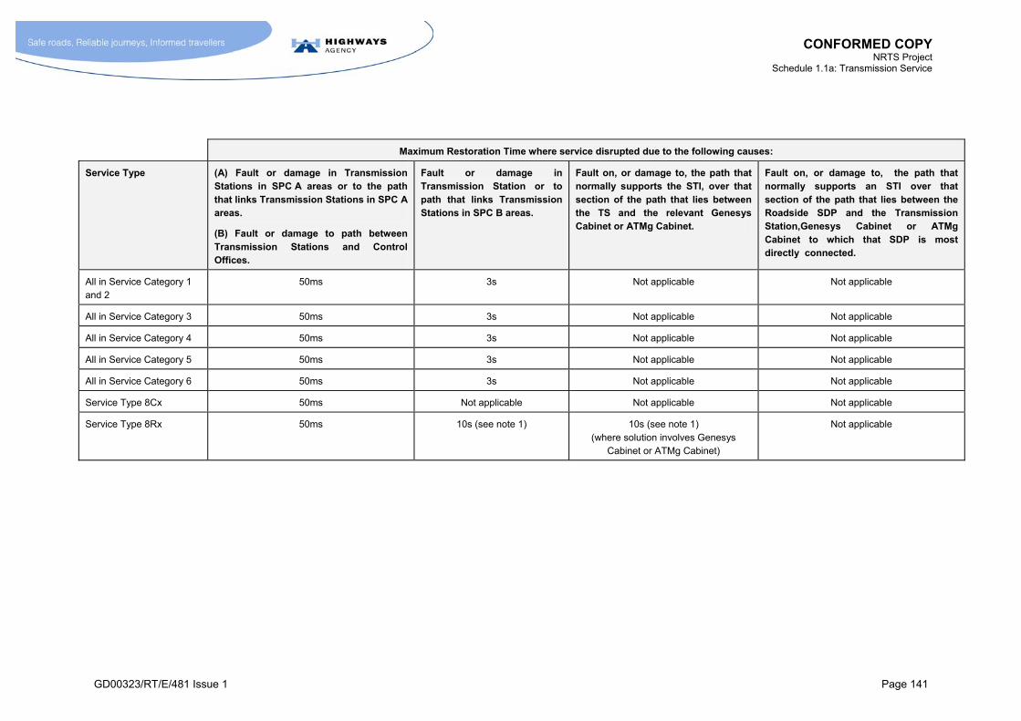
CONFORMED COPY NRTS Project
Schedule 1.1a: Transmission Service
GD00323/RT/E/481 Issue 1 Page 141
Maximum Restoration Time where service disrupted due to the following causes:
Service Type (A) Fault or damage in Transmission Stations in SPC A areas or to the path that links Transmission Stations in SPC A areas.
(B) Fault or damage to path between Transmission Stations and Control Offices.
Fault or damage in Transmission Station or to path that links Transmission Stations in SPC B areas.
Fault on, or damage to, the path that normally supports the STI, over that section of the path that lies between the TS and the relevant Genesys Cabinet or ATMg Cabinet.
Fault on, or damage to, the path that normally supports an STI over that section of the path that lies between the Roadside SDP and the Transmission Station,Genesys Cabinet or ATMg Cabinet to which that SDP is most directly connected.
All in Service Category 1 and 2
50ms 3s Not applicable Not applicable
All in Service Category 3 50ms 3s Not applicable Not applicable
All in Service Category 4 50ms 3s Not applicable Not applicable
All in Service Category 5 50ms 3s Not applicable Not applicable
All in Service Category 6 50ms 3s Not applicable Not applicable
Service Type 8Cx 50ms Not applicable Not applicable Not applicable
Service Type 8Rx 50ms 10s (see note 1) 10s (see note 1) (where solution involves Genesys
Cabinet or ATMg Cabinet)
Not applicable
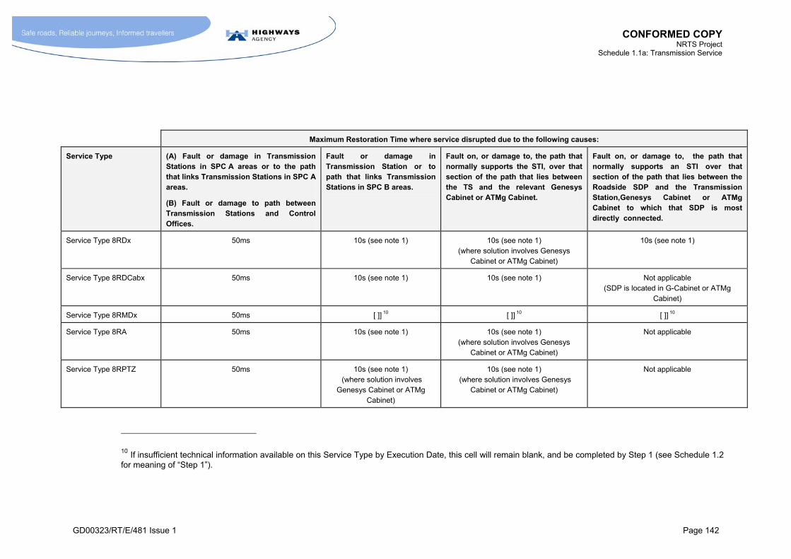
CONFORMED COPY NRTS Project
Schedule 1.1a: Transmission Service
GD00323/RT/E/481 Issue 1 Page 142
Maximum Restoration Time where service disrupted due to the following causes:
Service Type (A) Fault or damage in Transmission Stations in SPC A areas or to the path that links Transmission Stations in SPC A areas.
(B) Fault or damage to path between Transmission Stations and Control Offices.
Fault or damage in Transmission Station or to path that links Transmission Stations in SPC B areas.
Fault on, or damage to, the path that normally supports the STI, over that section of the path that lies between the TS and the relevant Genesys Cabinet or ATMg Cabinet.
Fault on, or damage to, the path that normally supports an STI over that section of the path that lies between the Roadside SDP and the Transmission Station,Genesys Cabinet or ATMg Cabinet to which that SDP is most directly connected.
Service Type 8RDx 50ms 10s (see note 1) 10s (see note 1) (where solution involves Genesys
Cabinet or ATMg Cabinet)
10s (see note 1)
Service Type 8RDCabx 50ms 10s (see note 1) 10s (see note 1) Not applicable (SDP is located in G-Cabinet or ATMg
Cabinet)
Service Type 8RMDx 50ms [ ]] 10 [ ]] 10 [ ]] 10
Service Type 8RA 50ms 10s (see note 1) 10s (see note 1) (where solution involves Genesys
Cabinet or ATMg Cabinet)
Not applicable
Service Type 8RPTZ 50ms 10s (see note 1) (where solution involves
Genesys Cabinet or ATMg Cabinet)
10s (see note 1) (where solution involves Genesys
Cabinet or ATMg Cabinet)
Not applicable
10 If insufficient technical information available on this Service Type by Execution Date, this cell will remain blank, and be completed by Step 1 (see Schedule 1.2 for meaning of “Step 1”).
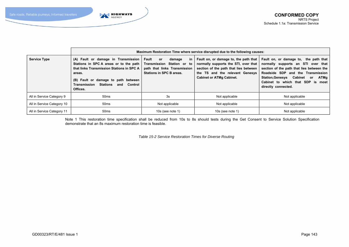
CONFORMED COPY NRTS Project
Schedule 1.1a: Transmission Service
GD00323/RT/E/481 Issue 1 Page 143
Maximum Restoration Time where service disrupted due to the following causes:
Service Type (A) Fault or damage in Transmission Stations in SPC A areas or to the path that links Transmission Stations in SPC A areas.
(B) Fault or damage to path between Transmission Stations and Control Offices.
Fault or damage in Transmission Station or to path that links Transmission Stations in SPC B areas.
Fault on, or damage to, the path that normally supports the STI, over that section of the path that lies between the TS and the relevant Genesys Cabinet or ATMg Cabinet.
Fault on, or damage to, the path that normally supports an STI over that section of the path that lies between the Roadside SDP and the Transmission Station,Genesys Cabinet or ATMg Cabinet to which that SDP is most directly connected.
All in Service Category 9 50ms 3s Not applicable Not applicable
All in Service Category 10 50ms Not applicable Not applicable Not applicable
All in Service Category 11 50ms 10s (see note 1) 10s (see note 1) Not applicable
Note 1 This restoration time specification shall be reduced from 10s to 8s should tests during the Get Consent to Service Solution Specification demonstrate that an 8s maximum restoration time is feasible.
Table 15-2 Service Restoration Times for Diverse Routing

CONFORMED COPY NRTS Project
Schedule 1.1a: Transmission Service
GD00323/RT/E/481 Issue 1 Page 144
15.15 Resilience to Electricity Supply Outages
15.15.1 [Not Used]
15.15.2 [Not Used]
15.15.3 M After the Build Completion Date, NRTS Co shall ensure that the Service Type Instances meet the requirements identified in Table 15-3 in the event of an electricity supply failure. Prior to the Build Completion Date, NRTS Co shall provide resilience arrangements for electricity supply outages using the arrangements that are currently in place.
Note: compliance is required for each line of the Table 15-3.
15.15.4 [Not Used]
15.15.5 M Any battery back-up arrangements employed by NRTS Co shall be such that the recovery time TR is less than five times the back-up time TB, where:
TB is the maximum time for which the battery back-up arrangements are required to support autonomous operation;
TR is the time taken for the battery back-up arrangements to recharge from a point where autonomous operation has occurred for a period equal to TB to a point where the battery back-up arrangements are capable of supporting autonomous operation for a period of at least 80% of TB.

CONFORMED COPY NRTS Project
Schedule 1.1a: Transmission Service
GD00323/RT/E/481 Issue 1 Page 145
Requirement Identity
Context for Requirement Requirement
a NRTS Co’s network management facilities NRTS Co’s shall have the capability to continue operating its network management facilities in the event of a failure of the supply from the local REC to the site of its main network management facilities.
b At locations where NRTS Co is sharing an electricity supply with the HA and the HA is providing standby generators intended to back-up the electricity supply in the event of a failure in the supply from the REC.
All STIs shall continue to function normally for at least 20 minutes after the failure of the HA backed-up supply (i.e. where no mains supply is being delivered to NRTS Co equipment from neither the REC nor the HA standby generator) and where NRTS Co was not responsible for that failure of supply.
c Locations where NRTS Co equipment is supporting a significant part (e.g. more than 10%) of the traffic in a CO area (e.g. a Transmission Station or other equivalent point of traffic concentration on the NRTS Co network.)
All the STIs that normally flow through that point of concentration shall continue to provide service in the event of a failure of the REC supply (where NRTS Co was not the cause of the failure) for:
a period at least 24 hours autonomous operation i.e. without the need for special
equipment to be transported to that site (for example transportable generators,
batteries, fuel etc.);
a period of at least 5 days for REC supply failures affecting at least 5 sites
simultaneously.
d Roadside NRTS Co equipment that meets both the following conditions:
it normally requires an REC supply;
it supports one or more Service Type Instances supporting
Emergency Roadside Telephones
The STI(s) normally supported by the Roadside NRTS Co equipment shall continue to function for a period of at least:
24 hours after the failure of the REC supply to the aforementioned Roadside
NRTS Co equipment, without the need for special equipment to be transported to
that site (for example transportable generators, batteries, fuel etc.)

CONFORMED COPY NRTS Project
Schedule 1.1a: Transmission Service
GD00323/RT/E/481 Issue 1 Page 146
Requirement Identity
Context for Requirement Requirement
e Roadside NRTS Co equipment that meets both of the following conditions:
it normally requires an REC supply;
it forms part of the electronic transmission path for STIs
whose downstream SDPs are connected to HA equipment
that use a different REC supply to the one supporting the
aforementioned Roadside NRTS Co equipment.
The STI(s) whose electronic transmission path is normally supported by the Roadside NRTS Co equipment shall continue to function for a period of at least:
24 hours after the failure of the REC supply to the aforementioned Roadside
NRTS Co equipment, without the need for special equipment to be transported to
that site (for example transportable generators, batteries, fuel etc.).
f Roadside NRTS Co equipment that normally requires an REC supply and that supports one STI (other than STI that support ERT).
Not specified
Table 15-3 Electrical Resilience Requirements
CONFORMED COPY NRTS Project
Schedule 1.1a: Transmission Service
GD00323/RT/E/481 Issue 1 Page 147
15.16 Commercial Exploitation of Spare Network Capacity
15.16.1 [Not Used]
15.16.2 [Not Used]
15.16.3 M NRTS Co shall not use network capacity, supplied as part of the NRTS Project, for the provision of commercial services other than that network capacity identified in Annex L. All network capacity, other than that identified in Annex L shall be available for the supply of the Transmission Service to the HA.
15.16.3.1 M Capacity identified for the provision of commercial services shall not be included in the Capacity Model. (See section 17.5.)
15.16.4 [Not Used]
15.16.5 [Not Used]
15.16.6 M NRTS Co shall not lease duct space to third parties.
15.16.7 M Commercial exploitation of spare network capacity shall be subject inter alia to the Appearance and Impact on Surroundings constraint and the Location of Equipment and Infrastructure constraint (Schedule 1.3 section 2.2 and section 2.17).
15.16.8 [Not Used]
15.16.9 M NRTS Co shall offer Commercial Transmission Services on an open and non-discriminatory basis. This means NRTS Co shall:
publish the prices it will charge for providing commercial transmission services;
ensure that prices are within the range of prices currently offered by competitors in the marketplace;
charge the same prices to any customer, including any customer that is an associated company of NRTS Co or its shareholders;
charge the same prices to its parent or subsidiary companies as it charges to the other customers, including any customer that is an associated company of NRTS Co or its shareholders;
make available a standard contract with customers, including any customer that is an associated company of NRTS Co or its shareholders;
enter into contracts on substantially the same terms with any customer, including any customer that is an associated company of NRTS Co or its shareholders;
seek HA approval for any significant departure from the standard terms or the standard pricing;
follow a standard procedure in its dealings with all customers;
allocate spare transmission capacity on a fair basis between customers, including any customer that is an associated company of NRTS Co or its shareholders.

CONFORMED COPY NRTS Project
Schedule 1.1a: Transmission Service
GD00323/RT/E/481 Issue 1 Page 148
15.17 Use of the Coleshill Computer Centre
Background
15.17.1 [Not Used]
15.17.2 [Not Used]
15.17.3 [Not Used]
15.17.4 [Not Used]
15.17.5 [Not Used]
15.17.6 [Not Used]
15.17.7 [Not Used]
15.17.8 [Not Used]
Potential Role of NRTS Co
15.17.9 [Not Used]
15.17.10 [Not Used]
15.17.11 M NRTS Co shall act as building manager for the Coleshill Computer Centre. In this capacity, under the direction of the HA, NRTS Co shall:
a) act as the HA's representative for:
any party requiring access to the building;
any HA personnel who manage projects that may be affected by or affect works at the building;
anyone requiring the arrangement of meetings to be held within the building;
any Service Providers to the building;
any parties with equipment based within the building.
b) report to the Coleshill User Groups at the quarterly meetings of all activities within the building;
c) regularly report to the HA on the condition of the building and its services and advise the HA of requirements for major remedial or renewal works;
d) create and maintain a programme of works for the site;
e) provide an interface to external service providers for:
fire protection system;
intruder alarm system;
building maintenance services.

CONFORMED COPY NRTS Project
Schedule 1.1a: Transmission Service
GD00323/RT/E/481 Issue 1 Page 149
f) establish and manage the contracts necessary for:
building maintenance;
generator maintenance;
fire protection systems;
air conditioning;
cleaning;
security and access control system.
g) create and maintain a Coleshill Computer Centre User Guide;
h) highlight any Health & Safety issues on behalf of the HA;
i) generate and maintain a Health and Safety file for Coleshill Computer Centre;
j) manage the existing rooms and building services to maximise the use of the Coleshill Computer Centre for the benefit of the HA;
k) manage power and telecommunications services on behalf of other users of the Coleshill Computer Centre;
l) allocate appropriate room and floor space for any new equipment that is to be installed.
Space Availability at Coleshill
15.17.12 M For space availability at Coleshill, see Schedule 12.

CONFORMED COPY NRTS Project
Schedule 1.1a: Transmission Service
GD00323/RT/E/481 Issue 1 Page 150
16 SERVICE LEVEL REQUIREMENTS
16.1 [Not Used]
16.2 [Not Used]
16.3 Outage
16.3.1 M Outage shall be defined as having occurred when an Instance of a Service Type:
is not functioning; or
when an Outage Trigger has occurred as defined in Annex M
16.4 Outage Hours
16.4.1 M Outage Hours for an Outage shall be defined as the elapsed time in hours or parts thereof, between Events A and B, where:
Event A is the earliest of the following:
the time the fault was logged as having started in NRTS Co’s own systems, including NRTS Co’s network management systems;
the time the fault appears to have started from the analysis of COBS or equivalent sources of data (see paragraph 15.10.9), where:
a) in the case of NRTS Attributable COBS Hard Faults (defined in paragraph 16.4.5), the start time for the fault condition shall be deemed to be the time stated in the COBS “Fault Report” for the start of that fault;
b) in the case of NRTS Attributable COBS Intermittent Faults (defined in paragraph 16.4.6), the start time for the fault condition shall be as defined in paragraph 16.4.7;
the time the fault was discovered by NRTS Co personnel;
the time at which NRTS Co was notified about the fault by HA personnel, or parties designated by the HA, or the Police.
Event B is when the fault causing the Outage is rectified, providing:
the STI meets its Performance Requirements; and,
any tests requested by the HA have been carried out; and,
the STI continues to operate normally and continuously (i.e. without intermittent faults) for a subsequent period of at least 48 hours.
16.4.2 M In connection with paragraph 16.4.1, for the avoidance of doubt, if intermittent faults occur, the state of Outage is regarded as persisting until that point in time that marks the start of at least 48 hours of operation free from intermittent faults due to the same cause as gave rise to Event A.
16.4.3 M NRTS Co shall undertake such tests as are reasonable to satisfy itself that the Service Type Instance is operating satisfactorily before regarding Event B as having occurred.
16.4.3.1 M HA reserves the right to require NRTS Co to undertake a full acceptance test to demonstrate that normal operation has been restored. Provided requirement 16.4.3 is satisfied, the performance of such tests shall not be regarded as a precondition for Event B.

CONFORMED COPY NRTS Project
Schedule 1.1a: Transmission Service
GD00323/RT/E/481 Issue 1 Page 151
16.4.4 M In calculating Outage Time, no distinction shall be made between elapsed time that occurs inside normal working hours and elapsed time that occurs outside normal working hours i.e. Outage Time is calculated on a 24 hour a day, 7 day a week, 365 or 366 day per year basis.
NRTS Attributable COBS Hard Fault
16.4.5 M A NRTS Attributable COBS Hard Fault shall apply to faults that are detected by COBS and logged on HALOGEN, and shall be defined as a condition where a fault has occurred that is attributable to the NRTS Transmission Service and the duration of the fault, measured in terms of the time difference between the time shown in the COBS Fault Message log entry and the time shown in the COBS “Fault Cleared” log entry, is greater than, or equal to, 5 minutes.
NRTS Attributable COBS Intermittent Fault
16.4.6 M A NRTS Attributable COBS Intermittent Fault shall apply to faults that are detected by COBS and logged on HALOGEN, and shall be defined as a condition where the cause of the faults is attributable to the NRTS Co Transmission Service and one of the following criteria is satisfied:
Criterion 1: the faults give rise to COBS “Intermittent Fault” messages (where the HA has configured the COBS to generate Intermittent Fault messages when 4 or more faults arising from the same cause occur within a 60-minute period);
Criterion 2: 4 or more faults (each less than 5 minutes) arising from the same cause occur within a 60-minute period (where the COBS system is not configured to generate Intermittent Fault messages);
Criterion 3: 10 or more faults (each less then 5 minutes) arising from the same cause occur within 30 consecutive days, except where such faults have already satisfied either Criterion 1 or Criterion 2.
16.4.6.1 M NRTS Co shall develop its NRTS Required Systems to analyse and report on the Intermittent Faults using the criteria defined in paragraph 16.4.6, and in the case of Criterion 3 shall develop its NRTS Required Systems to perform the analysis at regular intervals (which shall be as near real-time as reasonable endeavours during system development permit and at a minimum will be once every 24 hours).
16.4.7 M For a COBS Intermittent Fault, the start time of the fault shall be defined as follows:
For faults meeting Criterion 1 in paragraph 16.4.6, the time stated in the Intermittent Fault message;
For faults meeting Criterion 2 in paragraph 16.4.6, the time stated for the start of the fourth fault in the associated COBS Fault Message; or
For faults meeting Criterion 3 in paragraph 16.4.6, the time at which the analysis was undertaken that determined that there had been 10 or more faults within 30 consecutive days.
16.4.8 M For a COBS Intermittent Fault, Event B shall be deemed to have occurred at that point in time when the fault is rectified by NRTS Co provided this is followed by at least 48 hours of operation free from a re-occurrence of a COBS Fault Message due to the same underlying cause as gave rise to Event A.
CONFORMED COPY NRTS Project
Schedule 1.1a: Transmission Service
GD00323/RT/E/481 Issue 1 Page 152
16.4.9 M NRTS Co shall notify the HA (or parties designated by the HA) when a COBS Intermittent Fault has been rectified in accordance with a procedure agreed between the HA and NRTS Co that meets the following requirement:
NRTS Co shall notify parties agreed by the HA within 10 minutes of a COBS Intermittent Fault being updated as rectified in the NRTS systems.
16.4.10 M NRTS Co shall not be required to use COBS as a means of detecting faults where a failure of the HA (or the party designated by the HA) to clear an Intermittent Fault from COBS has the effect of masking the detection of subsequent faults arising from the same cause. Note: in such a case, Event A is defined as the earliest occurrence of any of other conditions listed under Event A in paragraph 16.4.1.
16.4.11 M Any reference to COBS in paragraph 16.4 shall also be regarded as a reference to systems serving an equivalent purpose for Service Categories 1 to 4, where such arrangements provide data that is available through HALOGEN or equivalent systems (in relation to this requirement, the conditions of paragraph 15.10.14 shall apply). This shall include arrangements for monitoring the performance of Service Category 4.
16.5 HA Planned Outage State
16.5.1 [Not Used]
16.5.2 M The HA Planned Outage State for a Service Type Instance shall be defined as occurring between Event C and Event D, where:
Event C is the point in time that a period of HA Planned Outage is scheduled to start; and
Event D is the point in time that the same period of HA Planned Outage is scheduled to finish, as stated in a Planned Outage Notice issued by the HA in accordance with the Maintain Service Continuity process (Schedule 1.2 section 5.3).
16.5.3 M For the avoidance of doubt, the HA Planned Outage state can only exist in relation to Outages requested by the HA. There shall be no allowance for any planned outages requested by NRTS Co, except in relation to the execution of permanent repairs to damage that have been caused by Defined Events. (See paragraph 16.7.2 for the definition of a Defined Event, and section 16.8 for the definition of a Defined Event Planned Permanent Repair.)

CONFORMED COPY NRTS Project
Schedule 1.1a: Transmission Service
GD00323/RT/E/481 Issue 1 Page 153
16.6 Access Prevented State
16.6.1 [Not Used]
16.6.2 M Except where paragraph 16.6.5 applies, the Access Prevented State for a Service Type Instance shall occur where activity to rectify a fault is prevented because:
a) access to the site needs to be arranged with the HA and the HA is responsible for a delay in granting such access (Note: the Access Prevented state only exists during the period of time between NRTS Co first requesting access to the site and the HA granting such access);
b) the Police are preventing access to a length of motorway where faulty equipment is located;
c) an abnormal health and safety risk to NRTS Co staff (e.g. significant risk of structure collapse) exists except where the health and safety risk is due to:
activities of NRTS Co;
Negligence by NRTS Co.
16.6.3 M The Access Prevented state shall be deemed to have ceased when access to the site is no longer prevented by the factors stated in paragraph 16.6.2 irrespective of whether or not the NRTS Co staff have arrived at the site.
16.6.4 M NRTS Co shall use reasonable endeavours:
a) to gain access to a site, including the use of alternative means where the normal means of gaining such access is not available; and
b) as part of the CRaP Process, to agree arrangements for sites occupied by the HA or other parties, such that access may be readily gained should the need for such access arise subsequently for fault rectification.
16.6.5 M Where NRTS Co has failed to satisfy the requirements of paragraph 16.6.4 in relation to a particular Outage, then the Access Prevented State shall be deemed not to have occurred over the period of time for which access would have been possible had the requirements in paragraph 16.6.4 been satisfied.
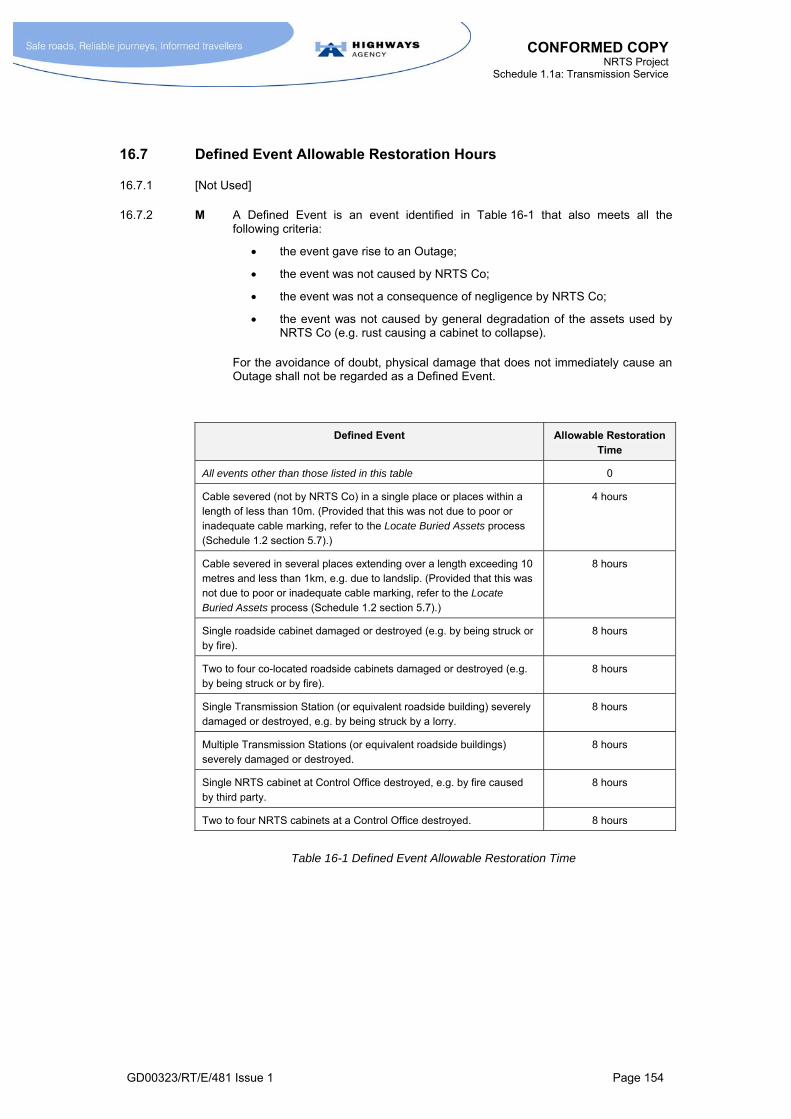
CONFORMED COPY NRTS Project
Schedule 1.1a: Transmission Service
GD00323/RT/E/481 Issue 1 Page 154
16.7 Defined Event Allowable Restoration Hours
16.7.1 [Not Used]
16.7.2 M A Defined Event is an event identified in Table 16-1 that also meets all the following criteria:
the event gave rise to an Outage;
the event was not caused by NRTS Co;
the event was not a consequence of negligence by NRTS Co;
the event was not caused by general degradation of the assets used by NRTS Co (e.g. rust causing a cabinet to collapse).
For the avoidance of doubt, physical damage that does not immediately cause an Outage shall not be regarded as a Defined Event.
Defined Event Allowable Restoration Time
All events other than those listed in this table 0
Cable severed (not by NRTS Co) in a single place or places within a length of less than 10m. (Provided that this was not due to poor or inadequate cable marking, refer to the Locate Buried Assets process (Schedule 1.2 section 5.7).)
4 hours
Cable severed in several places extending over a length exceeding 10 metres and less than 1km, e.g. due to landslip. (Provided that this was not due to poor or inadequate cable marking, refer to the Locate Buried Assets process (Schedule 1.2 section 5.7).)
8 hours
Single roadside cabinet damaged or destroyed (e.g. by being struck or by fire).
8 hours
Two to four co-located roadside cabinets damaged or destroyed (e.g. by being struck or by fire).
8 hours
Single Transmission Station (or equivalent roadside building) severely damaged or destroyed, e.g. by being struck by a lorry.
8 hours
Multiple Transmission Stations (or equivalent roadside buildings) severely damaged or destroyed.
8 hours
Single NRTS cabinet at Control Office destroyed, e.g. by fire caused by third party.
8 hours
Two to four NRTS cabinets at a Control Office destroyed. 8 hours
Table 16-1 Defined Event Allowable Restoration Time

CONFORMED COPY NRTS Project
Schedule 1.1a: Transmission Service
GD00323/RT/E/481 Issue 1 Page 155
16.8 Defined Event Planned Permanent Repair
16.8.1 [Not Used]
16.8.2 M A Defined Event Planned Permanent Repair occurs when all the following condition are met:
NRTS Co is undertaking planned activities to carry out a permanent repair on items that have been damaged previously in a Defined Event;
a temporary repair following the Defined Event has previously resulted in all STIs affected by the Defined Event being restored to normal service (i.e. Event B defined in paragraph 16.4.1 had occurred);
the time at which the planned permanent repair will take place has received the consent of the HA;
the HA have been given at least 24 hours notice of the time that the Outage required to carry out the permanent repair is going to start.
16.8.3 M The Defined Event Planned Permanent Repair Allowable Restoration Hours is of equal duration to the Defined Event Allowable Restoration Hours.
16.9 Defined Electricity Supply Failure State and Defined EMI Waived Fault State
Defined Electricity Supply Failure State
16.9.1 M A Defined Electricity Supply Failure State is defined as a condition where an Outage occurs due to electricity supply failure, where the nature of electricity supply failure exceeds those conditions for which NRTS Co is required to be resilient as defined in paragraph 15.15.
Defined EMI Waived Fault State
16.9.2 M A Defined EMI Waived Fault State occurs between Event E and Event F:
Event E – when the EMI Waived Fault State was deemed to have started in the EMI Waived Fault Notice;
Event F – when the EMI Waived Fault State ceases to apply as defined in Schedule 1.3 paragraphs 2.8.1.20 and 2.8.1.21.
16.9.3 M The conditions under which a EMI Waived Fault Notice is granted shall be as defined in Schedule 1.3 paragraph 2.8.1.15.

CONFORMED COPY NRTS Project
Schedule 1.1a: Transmission Service
GD00323/RT/E/481 Issue 1 Page 156
16.10 Attributable Outage Hours
16.10.1 [Not Used]
16.10.2 M The Attributable Outage Hours for a Service Type Instance for an Outage shall be defined as follows:
a) For Outages due to all causes where the Outage would not have occurred had the resilience requirements defined in section 15.14 been satisfied:
the Attributable Outage Hours shall be defined as the Outage Hours; (This requirement applies even if the proximate cause of the Outage was a Defined Event, Defined Event Planned Permanent Repair, a Defined Electricity Supply Failure State or Defined EMI Waived Fault State.)
Where a) does not apply:
For Outages due to any cause other than Defined Events, Defined Event Planned Permanent Repairs:
the Attributable Outage Hours shall be defined as the Outage Hours excluding any periods for which the STI was in one or more of the following states: HA Planned Outage, an Access Prevented State, a Defined Electricity Supply Failure State or a Defined EMI Waived Fault State;
b) For Outages due to Defined Events:
the Attributable Outage Hours shall be defined as the number of hours in excess of the Defined Event Allowable Restoration Hours for which the STI was in a state of Outage excluding any periods for which the STI was in one or more of the following states: HA Planned Outage, an Access Prevented State, a Defined Electricity Supply Failure State or a Defined EMI Waived Fault State;
c) For Outages due to Defined Event Planned Permanent Repairs:
the Attributable Outage Hours shall be defined as the number of hours in excess of the Defined Event Planned Permanent Repair Allowable Restoration Hours for which the STI was in a state of Outage excluding any periods for which the STI was in one or more of the following states: HA Planned Outage, an Access Prevented State, a Defined Electricity Supply Failure State or a Defined EMI Waived Fault State.
16.11 Reporting Period
16.11.1 M The Reporting Period shall be defined as the period of time over which the calculation of Availability shall take place.
16.11.2 M The Reporting Period shall be of one month duration.
16.12 Reporting Zone
16.12.1 M The Reporting Zone shall be defined as the geographical area containing the STIs for which the calculation of Availability shall take place.
16.12.2 [Not Used]

CONFORMED COPY NRTS Project
Schedule 1.1a: Transmission Service
GD00323/RT/E/481 Issue 1 Page 157
16.13 Potential Operating Hours
16.13.1 M The Potential Operating Hours for a Service Type shall be defined as the sum of the hours for all Instances of that Service Type falling within the Reporting Zone for which a Service Type Instance is Live over the Reporting Period.
16.13.2 M The term Live shall be defined as the state that exist between Activation and Deactivation of an STI. It shall be deemed to apply irrespective of whether the STI is in a state of Outage.
16.14 Total Outage Hours
16.14.1 M The Total Outage Hours for a Service Type shall be defined as the sum of all Outage Hours for all Instances of that Service Type falling within the Reporting Zone over the Reporting Period.
16.15 Total Attributable Outage Hours
16.15.1 M The Total Attributable Outage Hours for a Service Type shall be defined as the sum of all Attributable Outage Hours for all Instances of that Service Type falling within the Reporting Zone over the Reporting Period.
16.16 Availability
16.16.1 M The Availability for a particular Service Type over a particular Reporting Zone over a particular Reporting Period shall be defined as follows:
Availability = 1 – Total Attributable Outage Hours Potential Operating Hours
16.17 Unadjusted Availability
16.17.1 [Not Used]
16.17.2 M The Unadjusted Availability for a particular Service Type over a particular Reporting Zone over a particular Reporting Period shall be defined as follows:
Unadjusted Availability = 1 – Total Outage Hours Potential Operating Hours
16.18 [Not Used]

CONFORMED COPY NRTS Project
Schedule 1.1a: Transmission Service
GD00323/RT/E/481 Issue 1 Page 158
16.19 Reporting Requirements
16.19.1 M For each Service Type, NRTS Co shall report the following information at the end of each Reporting Period for each CO area and all CO areas taken together:
Total Outage Hours;
Total Attributable Outage Hours;
Unadjusted Availability;
Availability.
16.19.2 M NRTS Co shall employ arrangements for calculating Availability that are at least as rigorous, transparent and user-friendly as the NOMAD Fault Logging system, which is used to perform a broadly similar calculation for the Regional Maintenance Contractor maintenance contracts.
16.20 [Not Used]

CONFORMED COPY NRTS Project
Schedule 1.1a: Transmission Service
GD00323/RT/E/481 Issue 1 Page 159
17 HIGH LEVEL REQUIREMENTS PLACED ON THE BASE NETWORK
17.1 [Not Used]
17.2 The concept of a Base Network
17.2.1 [Not Used]
17.2.2 [Not Used]
17.2.3 M The term Base Network shall be defined as NRTS Co’s trunk network solution for providing:
by the Full Service Start Date, SPC A capabilities on those roads shown in Annex A of Schedule 12 as having SPC A capabilities, and SPC A or SPC B capabilities on those roads shown as having SPC B capabilities;
[Not Used]
17.2.3.1 [Not Used]
17.2.4 [Not Used]
17.2.5 [Not Used]
17.3 Key features of SPC A capability
17.3.1 [Not Used]
17.3.2 [Not Used]
17.3.3 [Not Used]
17.4 [Not Used]
17.5 Capacity of the Base Network
17.5.1 [Not Used]
17.5.2 [Not Used]
17.5.3 [Not Used]
17.5.4 M NRTS Co shall support the call-off of STIs until the point at which the Capacity Model indicates that no further call-offs can be accommodated.
17.5.5 [Not Used]
17.5.6 [Not Used]
17.5.7 [Not Used]
17.5.8 M NRTS Co shall upgrade the existing infrastructure to provide by the Build Completion Date the capacity required by the Capacity Model.
17.5.9 [Not Used]

CONFORMED COPY NRTS Project
Schedule 1.1a: Transmission Service
GD00323/RT/E/481 Issue 1 Page 160
Capacity Model
17.5.10 [Not Used]
17.5.11 [Not Used]
17.5.12 M Subject to the requirement in paragraph 17.5.14 being satisfied, the nominal capacity of the network used for the Capacity Model shall be defined as the capacity offered for the Base Network in Annex I. The term “Nominal Capacity” is to be understood in the sense that a 2.5Gbps link has a Nominal Capacity of 2.5Gbps.
17.5.13 M The Capacity Model shall apply the following rules in determining the ability of the solution to support any given geographical distribution of STIs and mixture of Service Types:
a) The capacity available for the support of STIs (the Useable Capacity) shall be assumed the Nominal Capacity less the following allowances for overheads:
POS (Packet-over-Sonnet) links = 10% of capacity.
GBE (Gigabit Ethernet) links = 20% of capacity.
b) The capacity consumption of various Service Types shall be less or equal to that defined in Annex I.
c) Traffic shall be diverse routed within the National and Regional Layers of the network (and in the Local Layer for those Service Types whose solutions involve Diverse Routing in the Local Layer).
d) The Capacity Model shall balance traffic, such that the equal volumes of traffic flow in either direction (i.e. East and West) from the point of ingress.
e) The volume of Real Time traffic shall not exceed 50% of the Useable Capacity.
f) All STIs shall be regarded as generating Real Time traffic, except for:
traffic associated with the retrieval of information from video storage and video web server traffic;
certain classes of Service Category 8 traffic, as determined by the HA (for example email).
g) The Access Line Utilisation for Service Category 8 Service Types shall be 100% at the SDP at the point ingress.
h) For Service Category 10 the Capacity Model shall assume that multicast “rendezvous points” are located following good design practice such that efficient use is made of network capacity.
17.5.14 M Within 3 months of the Execution Date, NRTS Co shall apply the Capacity Model to the actual spatial distribution of demand for the High Deployment Scenario as defined in the Registered Document of the High Deployment Scenario from the Invitation to Submit BAFO (‘ISB Volume 5, Part 3 – Version 0.94’). By this means, NRTS Co shall demonstrate that its solution is capable of supporting this level of demand.
17.5.15 M NRTS Co shall ensure that throughout the Contract Term its technical solution can support any level of demand that complies with the Capacity Model and the set of rules identified in paragraph 17.5.13. This includes, but is not limited to, ensuring the capacity consumption of each of the various Service Types does not exceed that defined in Annex I.

CONFORMED COPY NRTS Project
Schedule 1.1a: Transmission Service
GD00323/RT/E/481 Issue 1 Page 161
17.5.15.1 M Where the HA instructs NRTS Co to deploy STIs such that the actual loading of Real Time traffic on any network link is likely to exceed 50% of Useable Capacity (see paragraph 17.5.13a) and (e)), then the HA will waive any failures to meet performance requirements that can be attributed to the manner in which the loading of Real Time traffic has exceeded the 50% limit on the links concerned.
17.5.16 M Starting within 3 months of the Execution Date and at regular intervals throughout the Contract Term, NRTS Co shall maintain and update the Capacity Model so that the Capacity Model reflects the loading of the network derived from:
the actual locations of STIs
the various rules identified in paragraph 17.5.13 above.
17.5.17 M At the request of the HA, NRTS Co shall determine the effect of any proposed change in demand (e.g. a new CCTV scheme) on the utilisation of capacity within the Capacity Model by applying the various rules identified in paragraph 17.5.13 above.
17.6 Requirements for build programme
17.6.1 [Not Used]
17.6.2 [Not Used]
17.6.3 [Not Used]
17.6.4 M A condition for NRTS Co achieving the Build Completion Date shall be that NRTS Co demonstrates to the HA that the network satisfies the Build Phase Acceptance Tests. The Build Phase Acceptance Tests shall include the following:
Evidence that a network has been constructed and that installations are equipped in accordance with the design for which consent has been given.
Demonstrations that the network can support all Service Types (when suitably Enabled where appropriate), in accordance with their performance requirements.
Demonstrations that the performance requirements are met at various levels of traffic loading up to the agreed traffic ceiling defined by the Capacity Model.
The Build Phase Acceptance Tests shall be defined, in detail, in the Service Solution Specification.
17.7 Renewals
17.7.1 [Not Used]
17.7.2 [Not Used]
17.8 Regradings
17.8.1 [Not Used]
17.8.2 [Not Used]

CONFORMED COPY NRTS Project
Schedule 1.1a: Transmission Service
GD00323/RT/E/481 Issue 1 Page 162
17.9 Residual Life of Assets
17.9.1 [Not Used]
17.9.2 [Not Used]
17.9.3 [Not Used]
17.9.4 [Not Used]

CONFORMED COPY NRTS Project
Schedule 1.1a: Transmission Service
GD00323/RT/E/481 Issue 1 Page 163
A ANNEX A
SUMMARY OF SERVICE DEFINITIONS
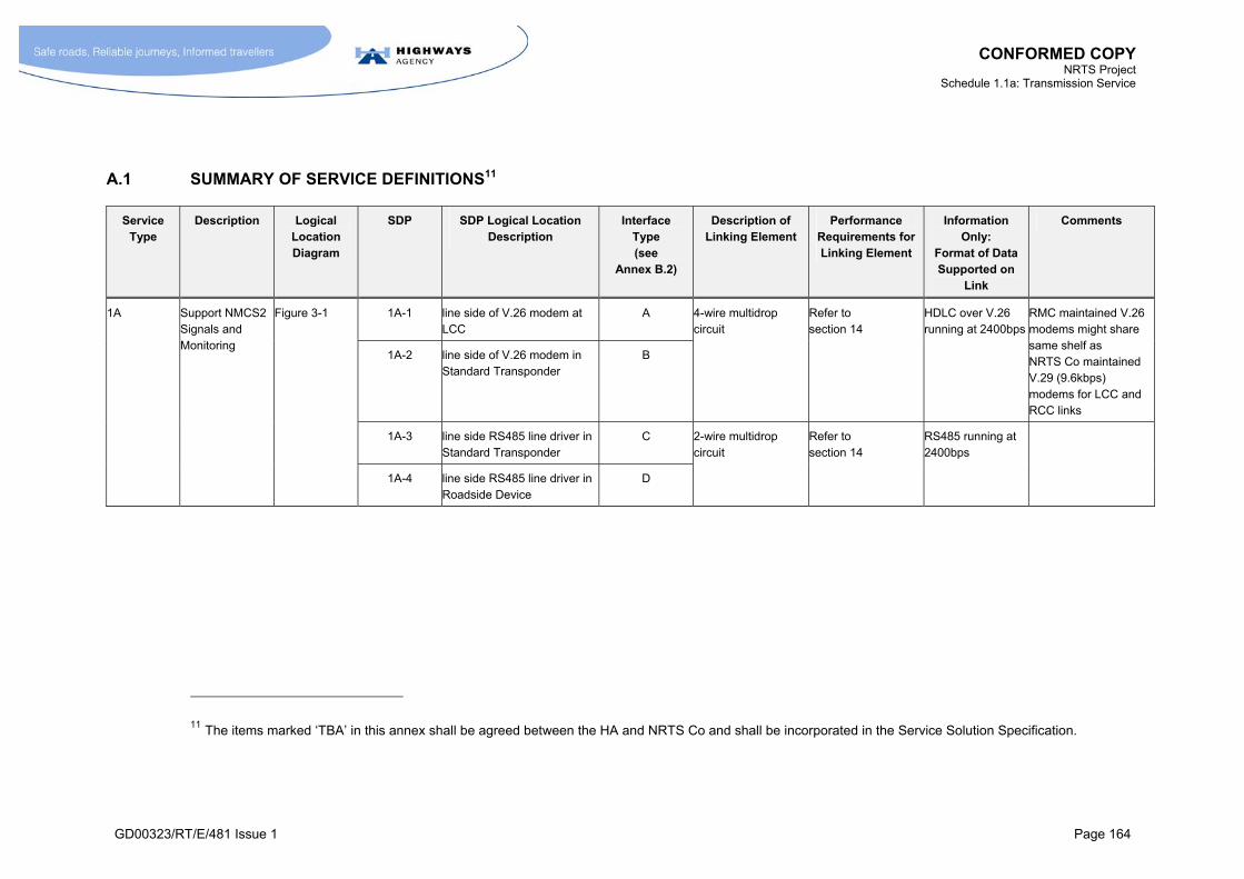
CONFORMED COPY NRTS Project
Schedule 1.1a: Transmission Service
GD00323/RT/E/481 Issue 1 Page 164
A.1 SUMMARY OF SERVICE DEFINITIONS11
Service Type
Description Logical Location Diagram
SDP SDP Logical Location Description
Interface Type (see
Annex B.2)
Description of Linking Element
Performance Requirements for Linking Element
Information Only:
Format of Data Supported on
Link
Comments
1A-1 line side of V.26 modem at LCC
A 1A Support NMCS2 Signals and Monitoring
Figure 3-1
1A-2 line side of V.26 modem in Standard Transponder
B
4-wire multidrop circuit
Refer to section 14
HDLC over V.26 running at 2400bps
RMC maintained V.26 modems might share same shelf as NRTS Co maintained V.29 (9.6kbps) modems for LCC and RCC links
1A-3 line side RS485 line driver in Standard Transponder
C
1A-4 line side RS485 line driver in Roadside Device
D
2-wire multidrop circuit
Refer to section 14
RS485 running at 2400bps
11 The items marked ‘TBA’ in this annex shall be agreed between the HA and NRTS Co and shall be incorporated in the Service Solution Specification.
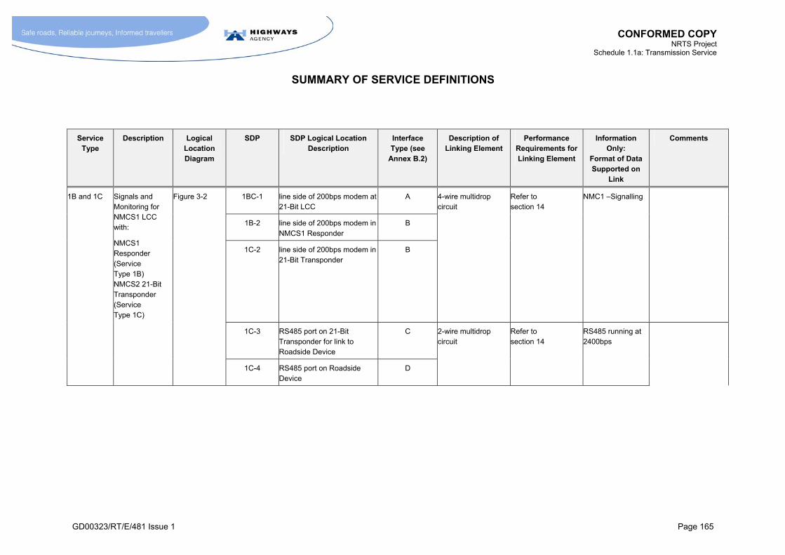
CONFORMED COPY NRTS Project
Schedule 1.1a: Transmission Service
SUMMARY OF SERVICE DEFINITIONS
GD00323/RT/E/481 Issue 1 Page 165
Service Type
Description Logical Location Diagram
SDP SDP Logical Location Description
Interface Type (see
Annex B.2)
Description of Linking Element
Performance Requirements for Linking Element
Information Only:
Format of Data Supported on
Link
Comments
1BC-1 line side of 200bps modem at 21-Bit LCC
A
1B-2 line side of 200bps modem inNMCS1 Responder
B
1B and 1C Signals and Monitoring for NMCS1 LCC with:
NMCS1 Responder (Service Type 1B) NMCS2 21-Bit Transponder (Service Type 1C)
Figure 3-2
1C-2 line side of 200bps modem in 21-Bit Transponder
B
4-wire multidrop circuit
Refer to section 14
NMC1 –Signalling
1C-3 RS485 port on 21-Bit Transponder for link to Roadside Device
C
1C-4 RS485 port on Roadside Device
D
2-wire multidrop circuit
Refer to section 14
RS485 running at 2400bps
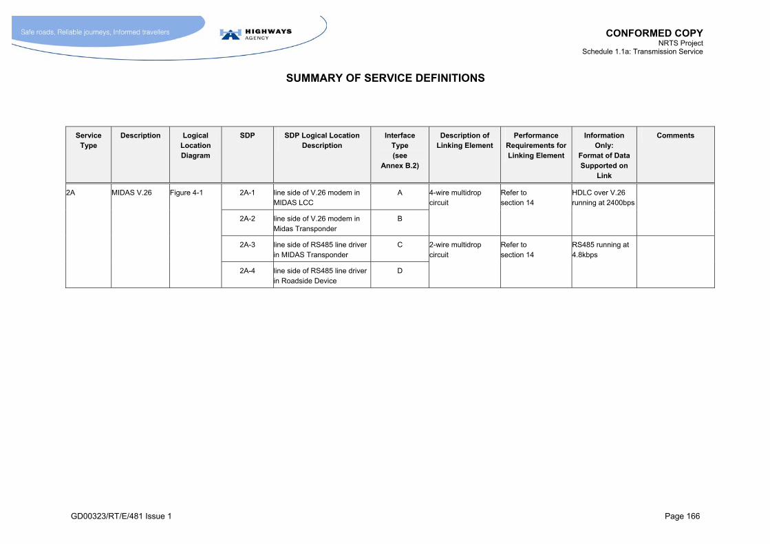
CONFORMED COPY NRTS Project
Schedule 1.1a: Transmission Service
SUMMARY OF SERVICE DEFINITIONS
GD00323/RT/E/481 Issue 1 Page 166
Service Type
Description Logical Location Diagram
SDP SDP Logical Location Description
Interface Type (see
Annex B.2)
Description of Linking Element
Performance Requirements for Linking Element
Information Only:
Format of Data Supported on
Link
Comments
2A-1 line side of V.26 modem in MIDAS LCC
A 2A MIDAS V.26 Figure 4-1
2A-2 line side of V.26 modem in Midas Transponder
B
4-wire multidrop circuit
Refer to section 14
HDLC over V.26 running at 2400bps
2A-3 line side of RS485 line driver in MIDAS Transponder
C
2A-4 line side of RS485 line driver in Roadside Device
D
2-wire multidrop circuit
Refer to section 14
RS485 running at 4.8kbps
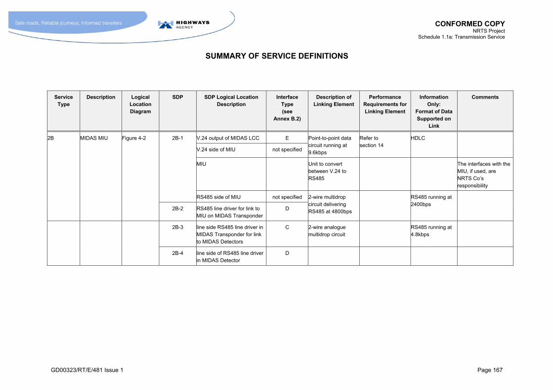
CONFORMED COPY NRTS Project
Schedule 1.1a: Transmission Service
SUMMARY OF SERVICE DEFINITIONS
GD00323/RT/E/481 Issue 1 Page 167
Service Type
Description Logical Location Diagram
SDP SDP Logical Location Description
Interface Type (see
Annex B.2)
Description of Linking Element
Performance Requirements for Linking Element
Information Only:
Format of Data Supported on
Link
Comments
2B-1 V.24 output of MIDAS LCC E 2B MIDAS MIU Figure 4-2
V.24 side of MIU not specified
Point-to-point data circuit running at 9.6kbps
Refer to section 14
HDLC
MIU Unit to convert between V.24 to RS485
The interfaces with the MIU, if used, are NRTS Co’s responsibility
RS485 side of MIU not specified
2B-2 RS485 line driver for link to MIU on MIDAS Transponder
D
2-wire multidrop circuit delivering RS485 at 4800bps
RS485 running at 2400bps
2B-3 line side RS485 line driver in MIDAS Transponder for link to MIDAS Detectors
C 2-wire analogue multidrop circuit
RS485 running at 4.8kbps
2B-4 line side of RS485 line driver in MIDAS Detector
D
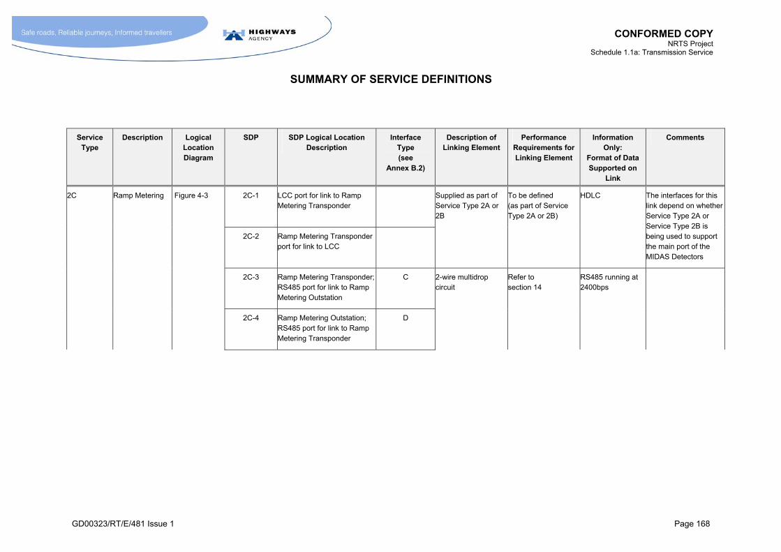
CONFORMED COPY NRTS Project
Schedule 1.1a: Transmission Service
SUMMARY OF SERVICE DEFINITIONS
GD00323/RT/E/481 Issue 1 Page 168
Service Type
Description Logical Location Diagram
SDP SDP Logical Location Description
Interface Type (see
Annex B.2)
Description of Linking Element
Performance Requirements for Linking Element
Information Only:
Format of Data Supported on
Link
Comments
2C-1 LCC port for link to Ramp Metering Transponder
To be defined (as part of Service Type 2A or 2B)
2C Ramp Metering Figure 4-3
2C-2 Ramp Metering Transponder port for link to LCC
Supplied as part of Service Type 2A or 2B
HDLC The interfaces for this link depend on whether Service Type 2A or Service Type 2B is being used to support the main port of the MIDAS Detectors
2C-3 Ramp Metering Transponder; RS485 port for link to Ramp Metering Outstation
C
2C-4 Ramp Metering Outstation; RS485 port for link to Ramp Metering Transponder
D
2-wire multidrop circuit
Refer to section 14
RS485 running at 2400bps

CONFORMED COPY NRTS Project
Schedule 1.1a: Transmission Service
SUMMARY OF SERVICE DEFINITIONS
GD00323/RT/E/481 Issue 1 Page 169
Service Type
Description Logical Location Diagram
SDP SDP Logical Location Description
Interface Type (see
Annex B.2)
Description of Linking Element
Performance Requirements for Linking Element
Information Only:
Format of Data Supported on
Link
Comments
2C (continued)
2C-5 Ramp Metering Outstation; RS485 port for link to Auxiliary port of MIDAS Detectors
C 2-wire multidrop circuit
Refer to section 14
RS485 running at 4.8kbps
2C-6 MIDAS Detectors; Auxiliary RS485 Port for link to Ramp Metering Outstation
D
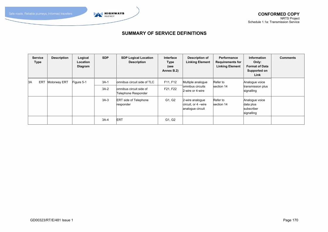
CONFORMED COPY NRTS Project
Schedule 1.1a: Transmission Service
SUMMARY OF SERVICE DEFINITIONS
GD00323/RT/E/481 Issue 1 Page 170
Service Type
Description Logical Location Diagram
SDP SDP Logical Location Description
Interface Type (see
Annex B.2)
Description of Linking Element
Performance Requirements for Linking Element
Information Only:
Format of Data Supported on
Link
Comments
3A-1 omnibus circuit side of TLC F11, F12 3A ERT Motorway ERT Figure 5-1
3A-2 omnibus circuit side of Telephone Responder
F21, F22
Multiple analogue omnibus circuits 2-wire or 4-wire
Refer to section 14
Analogue voice transmission plus signalling
3A-3 ERT side of Telephone responder
G1, G2 2-wire analogue circuit, or 4 –wire analogue circuit
Refer to section 14
Analogue voice data plus subscriber signalling
3A-4 ERT G1, G2
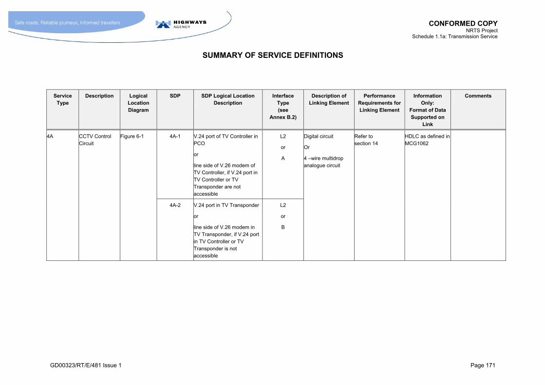
CONFORMED COPY NRTS Project
Schedule 1.1a: Transmission Service
SUMMARY OF SERVICE DEFINITIONS
GD00323/RT/E/481 Issue 1 Page 171
Service Type
Description Logical Location Diagram
SDP SDP Logical Location Description
Interface Type (see
Annex B.2)
Description of Linking Element
Performance Requirements for Linking Element
Information Only:
Format of Data Supported on
Link
Comments
4A-1 V.24 port of TV Controller in PCO
or
line side of V.26 modem of TV Controller, if V.24 port in TV Controller or TV Transponder are not accessible
L2
or
A
4A CCTV Control Circuit
Figure 6-1
4A-2 V.24 port in TV Transponder
or
line side of V.26 modem in TV Transponder, if V.24 port in TV Controller or TV Transponder is not accessible
L2
or
B
Digital circuit
Or
4 –wire multidrop analogue circuit
Refer to section 14
HDLC as defined in MCG1062
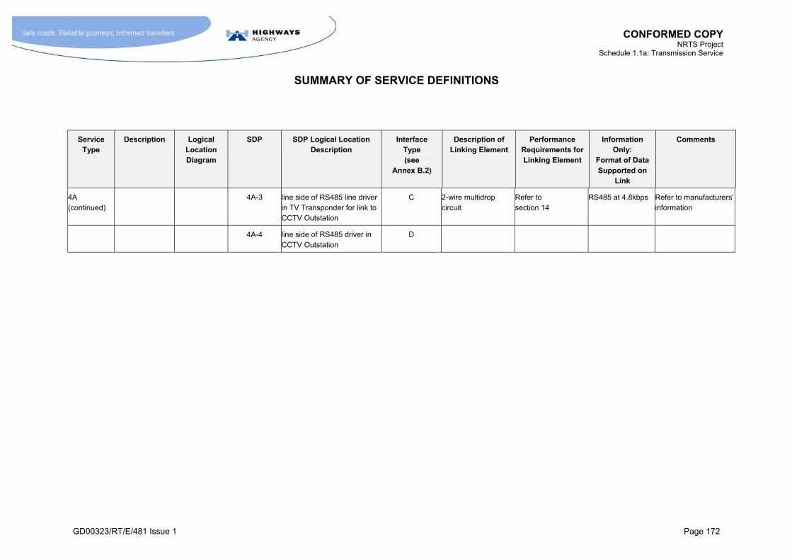
CONFORMED COPY NRTS Project
Schedule 1.1a: Transmission Service
SUMMARY OF SERVICE DEFINITIONS
GD00323/RT/E/481 Issue 1 Page 172
Service Type
Description Logical Location Diagram
SDP SDP Logical Location Description
Interface Type (see
Annex B.2)
Description of Linking Element
Performance Requirements for Linking Element
Information Only:
Format of Data Supported on
Link
Comments
4A (continued)
4A-3 line side of RS485 line driver in TV Transponder for link to CCTV Outstation
C 2-wire multidrop circuit
Refer to section 14
RS485 at 4.8kbps Refer to manufacturers’ information
4A-4 line side of RS485 driver in CCTV Outstation
D
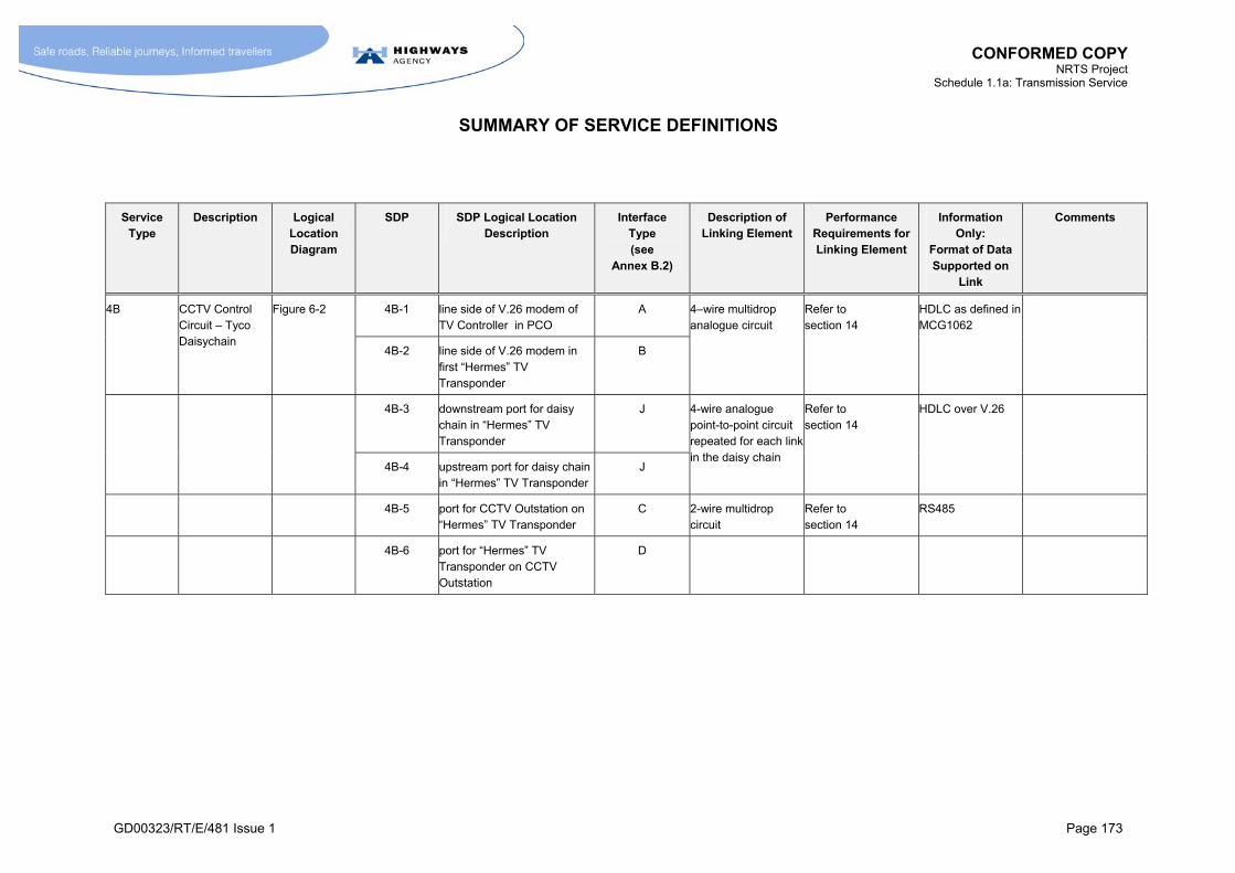
CONFORMED COPY NRTS Project
Schedule 1.1a: Transmission Service
SUMMARY OF SERVICE DEFINITIONS
GD00323/RT/E/481 Issue 1 Page 173
Service Type
Description Logical Location Diagram
SDP SDP Logical Location Description
Interface Type (see
Annex B.2)
Description of Linking Element
Performance Requirements for Linking Element
Information Only:
Format of Data Supported on
Link
Comments
4B-1 line side of V.26 modem of TV Controller in PCO
A 4B CCTV Control Circuit – Tyco Daisychain
Figure 6-2
4B-2 line side of V.26 modem in first “Hermes” TV Transponder
B
4–wire multidrop analogue circuit
Refer to section 14
HDLC as defined in MCG1062
4B-3 downstream port for daisy chain in “Hermes” TV Transponder
J
4B-4 upstream port for daisy chain in “Hermes” TV Transponder
J
4-wire analogue point-to-point circuit repeated for each link in the daisy chain
Refer to section 14
HDLC over V.26
4B-5 port for CCTV Outstation on “Hermes” TV Transponder
C 2-wire multidrop circuit
Refer to section 14
RS485
4B-6 port for “Hermes” TV Transponder on CCTV Outstation
D
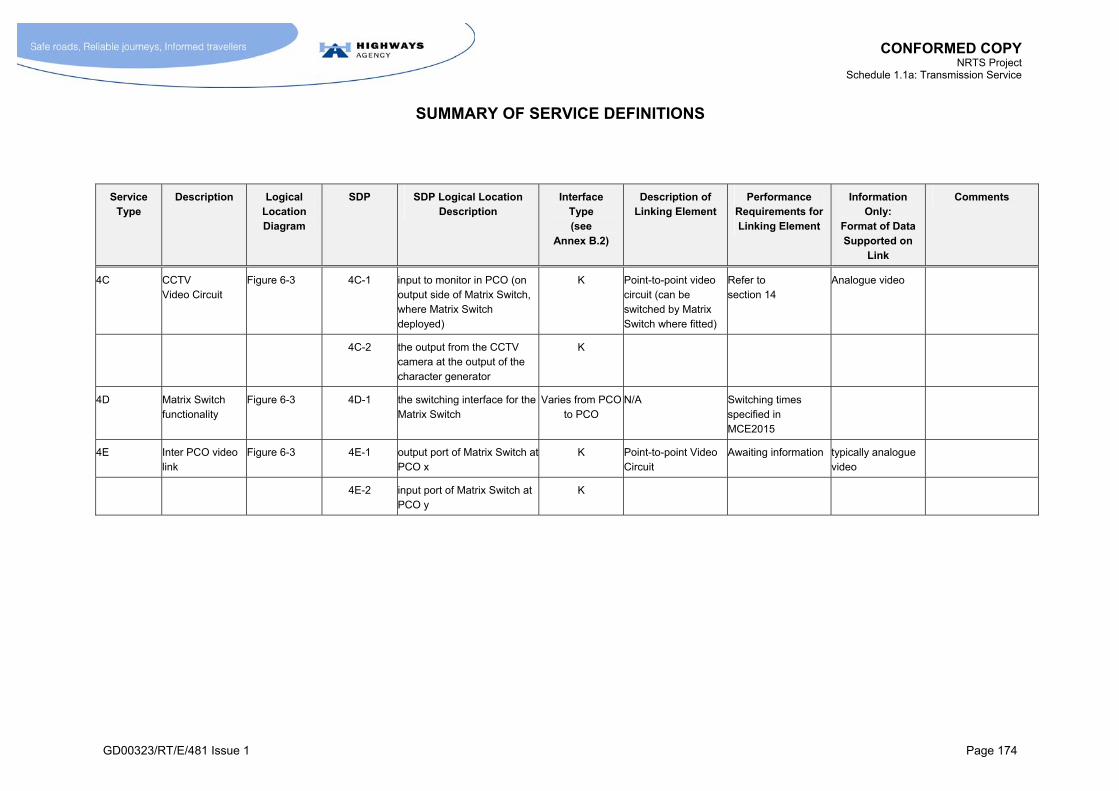
CONFORMED COPY NRTS Project
Schedule 1.1a: Transmission Service
SUMMARY OF SERVICE DEFINITIONS
GD00323/RT/E/481 Issue 1 Page 174
Service Type
Description Logical Location Diagram
SDP SDP Logical Location Description
Interface Type (see
Annex B.2)
Description of Linking Element
Performance Requirements for Linking Element
Information Only:
Format of Data Supported on
Link
Comments
4C
CCTV Video Circuit
Figure 6-3 4C-1 input to monitor in PCO (on output side of Matrix Switch, where Matrix Switch deployed)
K Point-to-point video circuit (can be switched by Matrix Switch where fitted)
Refer to section 14
Analogue video
4C-2 the output from the CCTV camera at the output of the character generator
K
4D Matrix Switch functionality
Figure 6-3 4D-1 the switching interface for the Matrix Switch
Varies from PCO to PCO
N/A Switching times specified in MCE2015
4E Inter PCO video link
Figure 6-3 4E-1 output port of Matrix Switch at PCO x
K Point-to-point Video Circuit
Awaiting information typically analogue video
4E-2 input port of Matrix Switch at PCO y
K
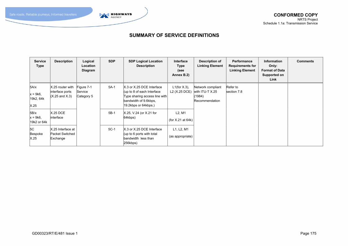
CONFORMED COPY NRTS Project
Schedule 1.1a: Transmission Service
SUMMARY OF SERVICE DEFINITIONS
GD00323/RT/E/481 Issue 1 Page 175
Service Type
Description Logical Location Diagram
SDP SDP Logical Location Description
Interface Type (see
Annex B.2)
Description of Linking Element
Performance Requirements for Linking Element
Information Only:
Format of Data Supported on
Link
Comments
5A/x
x = 9k6, 19k2, 64k
X.25
X.25 router with interface ports (X.25 and X.3)
5A-1 X.3 or X.25 DCE Interface (up to 8 of each Interface Type sharing access line with bandwidth of 9.6kbps, 19.2kbps or 64kbps.)
L1(for X.3), L2 (X.25 DCE)
5B/x x = 9k6, 19k2 or 64k
X.25 DCE interface
5B-1 X.25, V.24 (or X.21 for 64kbps)
L2, M1
(for X.21 at 64k)
5C Bespoke X.25
X.25 Interface at Packet Switched Exchange
Figure 7-1 Service Category 5
5C-1 X.3 or X.25 DCE Interface (up to 6 ports with total bandwidth less than 256kbps)
L1, L2, M1
(as appropriate)
Network compliant with ITU-T X.25 (1984) Recommendation
Refer to section 7.8
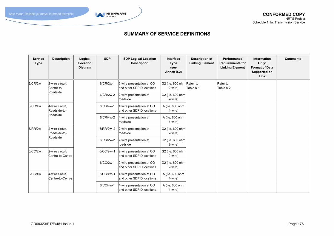
CONFORMED COPY NRTS Project
Schedule 1.1a: Transmission Service
SUMMARY OF SERVICE DEFINITIONS
GD00323/RT/E/481 Issue 1 Page 176
Service Type
Description Logical Location Diagram
SDP SDP Logical Location Description
Interface Type (see
Annex B.2)
Description of Linking Element
Performance Requirements for Linking Element
Information Only:
Format of Data Supported on
Link
Comments
6/CR/2w-1 2-wire presentation at CO and other SDP D locations
G2 (i.e. 600 ohm 2-wire)
6/CR/2w 2-wire circuit, Centre-to-Roadside
6/CR/2w-2 2-wire presentation at roadside
G2 (i.e. 600 ohm 2-wire)
6/CR/4w-1 4-wire presentation at CO and other SDP D locations
A (i.e. 600 ohm 4-wire)
6/CR/4w 4-wire circuit, Roadside-to-Roadside
6/CR/4w-2 4-wire presentation at roadside
A (i.e. 600 ohm 4-wire)
6/RR/2w–2 2-wire presentation at roadside
G2 (i.e. 600 ohm 2-wire)
6/RR/2w 2-wire circuit, Roadside-to-Roadside
6/RR/2w-2 2-wire presentation at roadside
G2 (i.e. 600 ohm 2-wire)
6/CC/2w–1 2-wire presentation at CO and other SDP D locations
G2 (i.e. 600 ohm 2-wire)
6/CC/2w 2-wire circuit, Centre-to-Centre
6/CC/2w-1 2-wire presentation at CO and other SDP D locations
G2 (i.e. 600 ohm 2-wire)
6/CC/4w–1 4-wire presentation at CO and other SDP D locations
A (i.e. 600 ohm 4-wire)
6/CC/4w 4-wire circuit, Centre-to-Centre
6/CC/4w-1 4-wire presentation at CO and other SDP D locations
A (i.e. 600 ohm 4-wire)
Refer to Table 8-1
Refer to Table 8-2
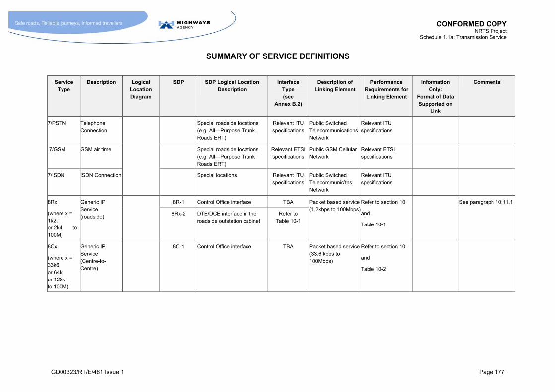
CONFORMED COPY NRTS Project
Schedule 1.1a: Transmission Service
SUMMARY OF SERVICE DEFINITIONS
GD00323/RT/E/481 Issue 1 Page 177
Service Type
Description Logical Location Diagram
SDP SDP Logical Location Description
Interface Type (see
Annex B.2)
Description of Linking Element
Performance Requirements for Linking Element
Information Only:
Format of Data Supported on
Link
Comments
7/PSTN Telephone Connection
Special roadside locations (e.g. All—Purpose Trunk Roads ERT)
Relevant ITU specifications
Public Switched Telecommunications Network
Relevant ITU specifications
7/GSM GSM air time Special roadside locations (e.g. All—Purpose Trunk Roads ERT)
Relevant ETSI specifications
Public GSM Cellular Network
Relevant ETSI specifications
7/ISDN ISDN Connection
Special locations Relevant ITU specifications
Public Switched Telecommunic’tns Network
Relevant ITU specifications
8R-1 Control Office interface TBA 8Rx
(where x = 1k2; or 2k4 to 100M)
Generic IP Service (roadside)
8Rx-2 DTE/DCE interface in the roadside outstation cabinet
Refer to Table 10-1
Packet based service (1.2kbps to 100Mbps)
Refer to section 10
and
Table 10-1
See paragraph 10.11.1
8Cx
(where x = 33k6 or 64k; or 128k to 100M)
Generic IP Service (Centre-to-Centre)
8C-1 Control Office interface TBA Packet based service (33.6 kbps to 100Mbps)
Refer to section 10
and
Table 10-2
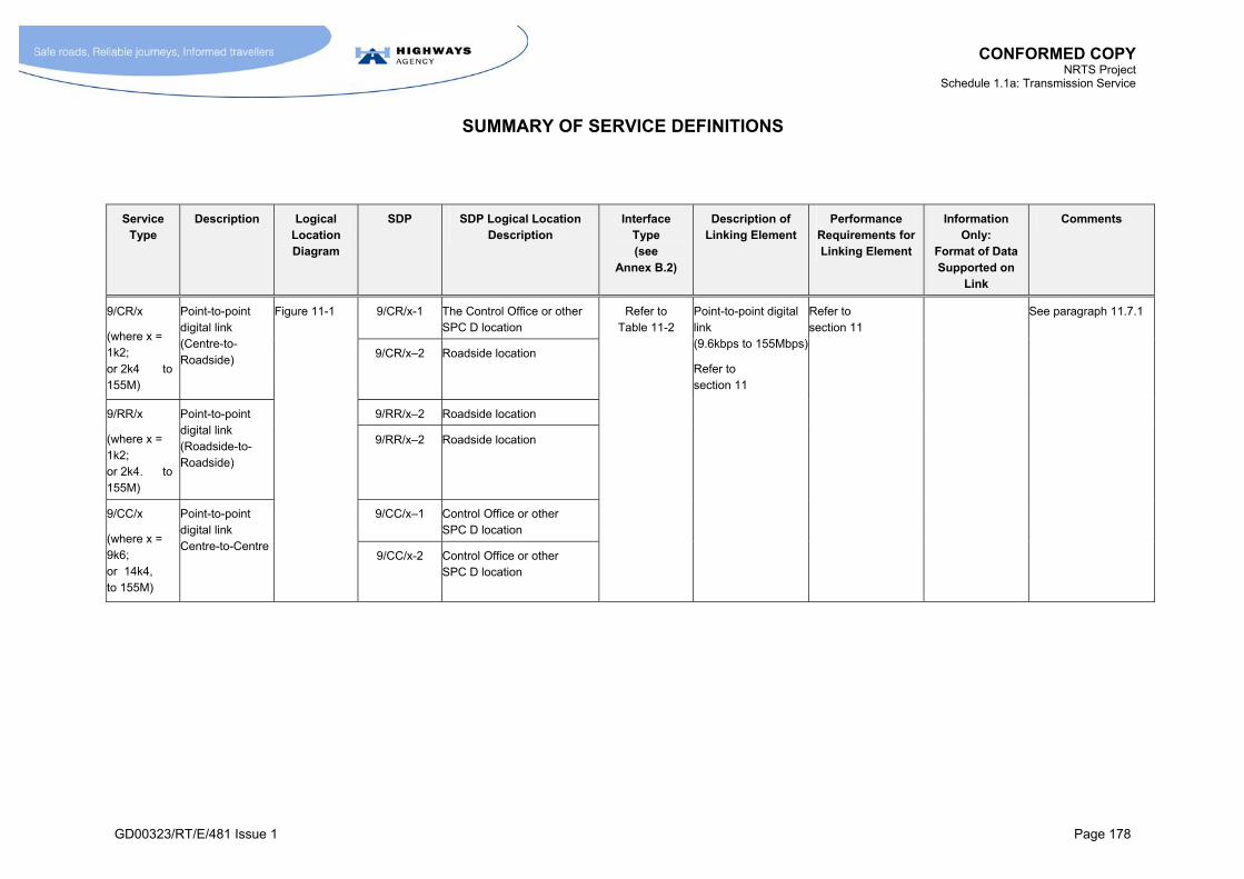
CONFORMED COPY NRTS Project
Schedule 1.1a: Transmission Service
SUMMARY OF SERVICE DEFINITIONS
GD00323/RT/E/481 Issue 1 Page 178
Service Type
Description Logical Location Diagram
SDP SDP Logical Location Description
Interface Type (see
Annex B.2)
Description of Linking Element
Performance Requirements for Linking Element
Information Only:
Format of Data Supported on
Link
Comments
9/CR/x-1 The Control Office or other SPC D location
9/CR/x
(where x = 1k2; or 2k4 to 155M)
Point-to-point digital link (Centre-to-Roadside)
9/CR/x–2 Roadside location
9/RR/x–2 Roadside location 9/RR/x
(where x = 1k2; or 2k4. to 155M)
Point-to-point digital link (Roadside-to-Roadside)
9/RR/x–2 Roadside location
9/CC/x–1 Control Office or other SPC D location
9/CC/x
(where x = 9k6; or 14k4, to 155M)
Point-to-point digital link Centre-to-Centre
Figure 11-1
9/CC/x-2 Control Office or other SPC D location
Refer to Table 11-2
Point-to-point digital link (9.6kbps to 155Mbps)
Refer to section 11
Refer to section 11
See paragraph 11.7.1
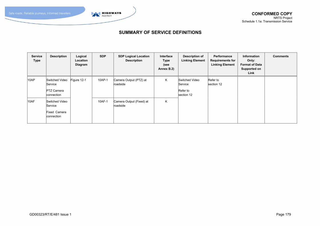
CONFORMED COPY NRTS Project
Schedule 1.1a: Transmission Service
SUMMARY OF SERVICE DEFINITIONS
GD00323/RT/E/481 Issue 1 Page 179
Service Type
Description Logical Location Diagram
SDP SDP Logical Location Description
Interface Type (see
Annex B.2)
Description of Linking Element
Performance Requirements for Linking Element
Information Only:
Format of Data Supported on
Link
Comments
10AP Switched Video Service
PTZ Camera connection
10AP-1 Camera Output (PTZ) at roadside
K
10AF Switched Video Service
Fixed Camera connection
Figure 12-1
10AF-1 Camera Output (Fixed) at roadside
K
Switched Video Service
Refer to section 12
Refer to section 12
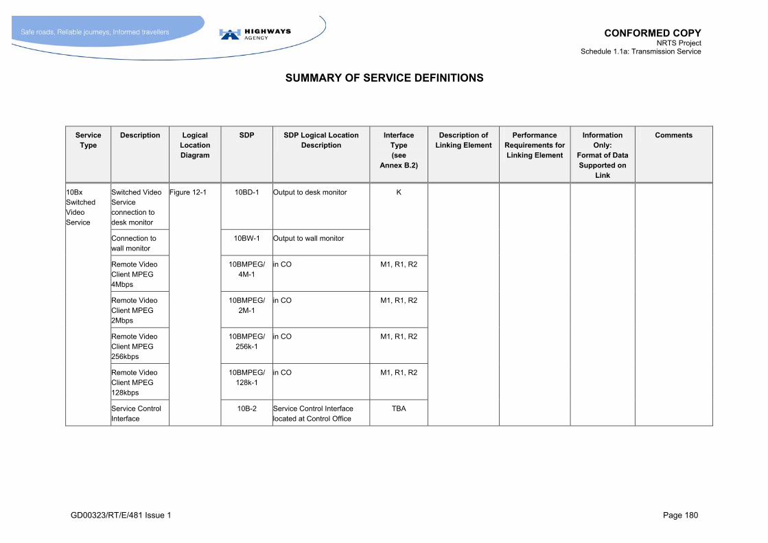
CONFORMED COPY NRTS Project
Schedule 1.1a: Transmission Service
SUMMARY OF SERVICE DEFINITIONS
GD00323/RT/E/481 Issue 1 Page 180
Service Type
Description Logical Location Diagram
SDP SDP Logical Location Description
Interface Type (see
Annex B.2)
Description of Linking Element
Performance Requirements for Linking Element
Information Only:
Format of Data Supported on
Link
Comments
Switched Video Service connection to desk monitor
10BD-1 Output to desk monitor
Connection to wall monitor
10BW-1 Output to wall monitor
K
Remote Video Client MPEG 4Mbps
10BMPEG/ 4M-1
in CO M1, R1, R2
Remote Video Client MPEG 2Mbps
10BMPEG/ 2M-1
in CO M1, R1, R2
Remote Video Client MPEG 256kbps
10BMPEG/ 256k-1
in CO M1, R1, R2
Remote Video Client MPEG 128kbps
10BMPEG/ 128k-1
in CO M1, R1, R2
10Bx Switched Video Service
Service Control Interface
Figure 12-1
10B-2 Service Control Interface located at Control Office
TBA
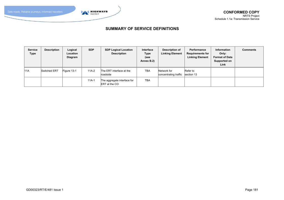
CONFORMED COPY NRTS Project
Schedule 1.1a: Transmission Service
SUMMARY OF SERVICE DEFINITIONS
GD00323/RT/E/481 Issue 1 Page 181
Service Type
Description Logical Location Diagram
SDP SDP Logical Location Description
Interface Type (see
Annex B.2)
Description of Linking Element
Performance Requirements for Linking Element
Information Only:
Format of Data Supported on
Link
Comments
11A Switched ERT Figure 13-1 11A-2 The ERT interface at the roadside
TBA Network for concentrating traffic
Refer to section 13
11A-1 The aggregate interface for ERT at the CO
TBA

CONFORMED COPY NRTS Project
Schedule 1.1a: Transmission Service
GD00323/RT/E/481 Issue 1 Page 182
B ANNEX B
DEFINITIONS OF SERVICE DELIVERY POINTS AND INTERFACE TYPES
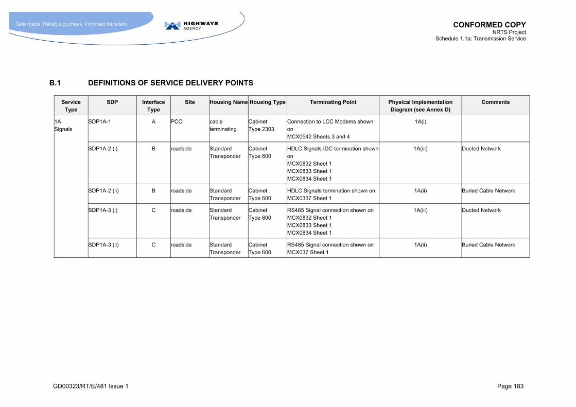
CONFORMED COPY NRTS Project
Schedule 1.1a: Transmission Service
GD00323/RT/E/481 Issue 1 Page 183
B.1 DEFINITIONS OF SERVICE DELIVERY POINTS
Service Type
SDP Interface Type
Site Housing Name Housing Type Terminating Point Physical Implementation Diagram (see Annex D)
Comments
1A Signals
SDP1A-1 A PCO cable terminating
Cabinet Type 2303
Connection to LCC Modems shown on MCX0542 Sheets 3 and 4
1A(i)
SDP1A-2 (i) B roadside Standard Transponder
Cabinet Type 600
HDLC Signals IDC termination shown on MCX0832 Sheet 1 MCX0833 Sheet 1 MCX0834 Sheet 1
1A(iii) Ducted Network
SDP1A-2 (ii) B roadside Standard Transponder
Cabinet Type 600
HDLC Signals termination shown on MCX0337 Sheet 1
1A(ii) Buried Cable Network
SDP1A-3 (i) C roadside Standard Transponder
Cabinet Type 600
RS485 Signal connection shown on MCX0832 Sheet 1 MCX0833 Sheet 1 MCX0834 Sheet 1
1A(iii) Ducted Network
SDP1A-3 (ii) C roadside Standard Transponder
Cabinet Type 600
RS485 Signal connection shown on MCX037 Sheet 1
1A(ii) Buried Cable Network
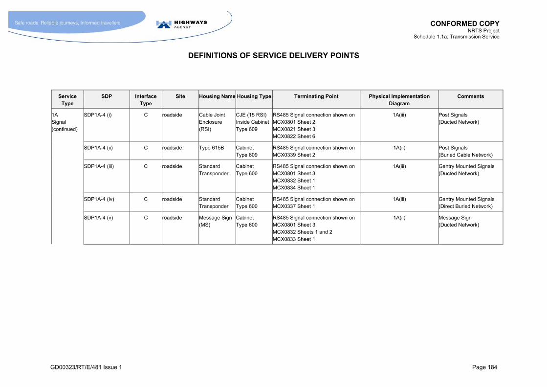
CONFORMED COPY NRTS Project
Schedule 1.1a: Transmission Service
DEFINITIONS OF SERVICE DELIVERY POINTS
GD00323/RT/E/481 Issue 1 Page 184
Service Type
SDP Interface Type
Site Housing Name Housing Type Terminating Point Physical Implementation Diagram
Comments
1A Signal (continued)
SDP1A-4 (i) C roadside Cable Joint Enclosure (RSI)
CJE (15 RSI) Inside Cabinet Type 609
RS485 Signal connection shown on MCX0801 Sheet 2 MCX0821 Sheet 3 MCX0822 Sheet 6
1A(iii) Post Signals (Ducted Network)
SDP1A-4 (ii) C roadside Type 615B Cabinet Type 609
RS485 Signal connection shown on MCX0339 Sheet 2
1A(ii) Post Signals (Buried Cable Network)
SDP1A-4 (iii) C roadside Standard Transponder
Cabinet Type 600
RS485 Signal connection shown on MCX0801 Sheet 3 MCX0832 Sheet 1 MCX0834 Sheet 1
1A(iii) Gantry Mounted Signals (Ducted Network)
SDP1A-4 (iv) C roadside Standard Transponder
Cabinet Type 600
RS485 Signal connection shown on MCX0337 Sheet 1
1A(iii) Gantry Mounted Signals (Direct Buried Network)
SDP1A-4 (v) C roadside Message Sign (MS)
Cabinet Type 600
RS485 Signal connection shown on MCX0801 Sheet 3 MCX0832 Sheets 1 and 2 MCX0833 Sheet 1
1A(ii) Message Sign (Ducted Network)

CONFORMED COPY NRTS Project
Schedule 1.1a: Transmission Service
DEFINITIONS OF SERVICE DELIVERY POINTS
GD00323/RT/E/481 Issue 1 Page 185
Service Type
SDP Interface Type
Site Housing Name Housing Type Terminating Point Physical Implementation Diagram
Comments
1A Signal (continued)
SDP1A-4 (vi) C roadside Message Sign (MS)
Cabinet Type 600
RS485 Signal connection shown on MCX0339 Sheet 1 MCX0339 Sheet 2 MCX0339 Sheet 3
1A(ii) Message Sign (Direct Buried Network)
SDP1A-4 (vii) C roadside Enhanced Message Sign (EMS)
Cabinet Type 600
RS485 Signal connection shown on MCX0801 Sheet 3 MCX0832 Sheets 1 and 2 MCX0833 Sheet 1
1A(iii) Enhanced Message Sign (Ducted Network)
SDP1A-4 (viii) C roadside Enhanced Message Sign (EMS)
Cabinet Type 600
RS485 Signal connection shown on MCX0339 Sheet 1 MCX0339 Sheet 2 MCX0339 Sheet 3
1A(ii) Enhanced Message Sign (Direct Buried Network)
SDP1A-4 (ix) C roadside Fog Detector Post Type 85 RS485 Fog Detector connection
As for Post 75 mounted signals
MCX 0152
1A(iii) Fog Detector (Ducted Network)
SDP1A-4 (x) C roadside Fog Detector Post Type 85 RS485 Fog Detector connection
As for Post 75 mounted signals
MCX 0152
1A(ii) Fog Detector (Direct Buried Network)
SDP1A-4 (xi) C roadside Post Mounted Signal (non median)
Post Type 75 RS485 MS connection
MCX 0152
1A(iii) Matrix Sign (Ducted Network)
SDP1A-4 (xii) C roadside Post Mounted Signal (non median)
Post Type 75 RS485 MS connection
MCX 0152
1A(ii) Matrix Sign (Direct Buried Network)
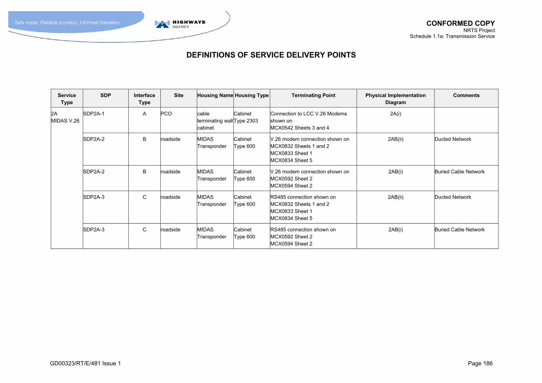
CONFORMED COPY NRTS Project
Schedule 1.1a: Transmission Service
DEFINITIONS OF SERVICE DELIVERY POINTS
GD00323/RT/E/481 Issue 1 Page 186
Service Type
SDP Interface Type
Site Housing Name Housing Type Terminating Point Physical Implementation Diagram
Comments
2A MIDAS V.26
SDP2A-1 A PCO cable terminating wall cabinet
Cabinet Type 2303
Connection to LCC V.26 Modems shown on MCX0542 Sheets 3 and 4
2A(i)
SDP2A-2 B roadside MIDAS Transponder
Cabinet Type 600
V.26 modem connection shown on MCX0832 Sheets 1 and 2 MCX0833 Sheet 1 MCX0834 Sheet 5
2AB(ii) Ducted Network
SDP2A-2 B roadside MIDAS Transponder
Cabinet Type 600
V.26 modem connection shown on MCX0592 Sheet 2 MCX0594 Sheet 2
2AB(i) Buried Cable Network
SDP2A-3 C roadside MIDAS Transponder
Cabinet Type 600
RS485 connection shown on MCX0832 Sheets 1 and 2 MCX0833 Sheet 1 MCX0834 Sheet 5
2AB(ii) Ducted Network
SDP2A-3 C roadside MIDAS Transponder
Cabinet Type 600
RS485 connection shown on MCX0592 Sheet 2 MCX0594 Sheet 2
2AB(i) Buried Cable Network
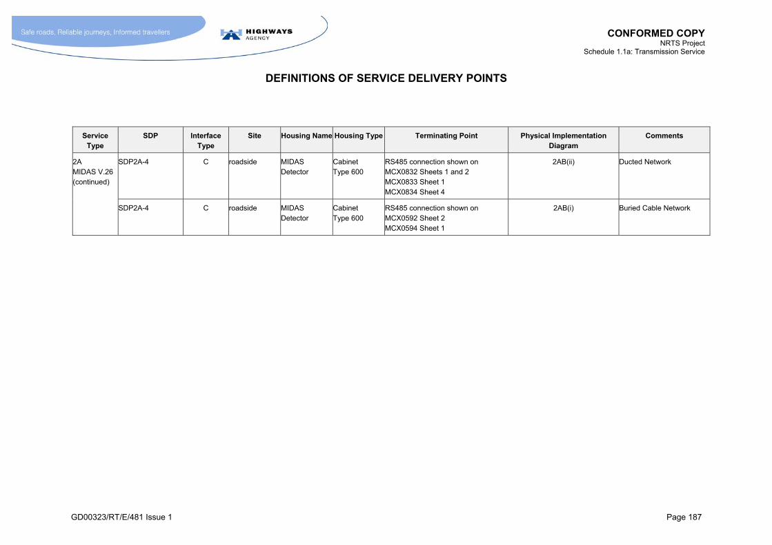
CONFORMED COPY NRTS Project
Schedule 1.1a: Transmission Service
DEFINITIONS OF SERVICE DELIVERY POINTS
GD00323/RT/E/481 Issue 1 Page 187
Service Type
SDP Interface Type
Site Housing Name Housing Type Terminating Point Physical Implementation Diagram
Comments
2A MIDAS V.26 (continued)
SDP2A-4 C roadside MIDAS Detector
Cabinet Type 600
RS485 connection shown on MCX0832 Sheets 1 and 2 MCX0833 Sheet 1 MCX0834 Sheet 4
2AB(ii) Ducted Network
SDP2A-4 C roadside MIDAS Detector
Cabinet Type 600
RS485 connection shown on MCX0592 Sheet 2 MCX0594 Sheet 1
2AB(i) Buried Cable Network
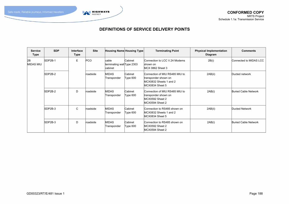
CONFORMED COPY NRTS Project
Schedule 1.1a: Transmission Service
DEFINITIONS OF SERVICE DELIVERY POINTS
GD00323/RT/E/481 Issue 1 Page 188
Service Type
SDP Interface Type
Site Housing Name Housing Type Terminating Point Physical Implementation Diagram
Comments
2B MIDAS MIU
SDP2B-1 E PCO cable terminating wall cabinet
Cabinet Type 2303
Connection to LCC V.24 Modems shown on MCX 0862 Sheet 3
2B(i) Connected to MIDAS LCC
SDP2B-2 roadside MIDAS Transponder
Cabinet Type 600
Connection of MIU RS485 MIU to transponder shown on MCX0832 Sheets 1 and 2 MCX0834 Sheet 5
2AB(ii) Ducted network
SDP2B-2 D roadside MIDAS Transponder
Cabinet Type 600
Connection of MIU RS485 MIU to transponder shown on MCX0592 Sheet 2 MCX0594 Sheet 2
2AB(i) Buried Cable Network
SDP2B-3 C roadside MIDAS Transponder
Cabinet Type 600
Connection to RS485 shown on MCX0832 Sheets 1 and 2 MCX0834 Sheet 5
2AB(ii) Ducted Network
SDP2B-3 D roadside MIDAS Transponder
Cabinet Type 600
Connection to RS485 shown on MCX0592 Sheet 2 MCX0594 Sheet 2
2AB(i) Buried Cable Network
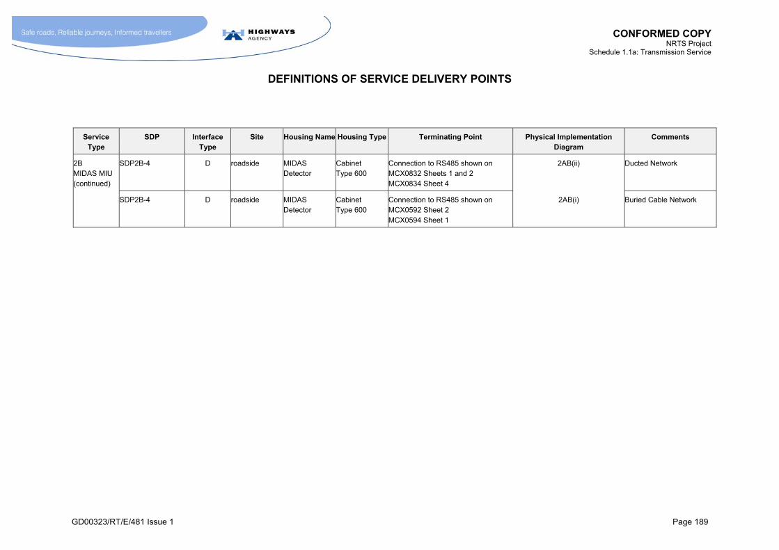
CONFORMED COPY NRTS Project
Schedule 1.1a: Transmission Service
DEFINITIONS OF SERVICE DELIVERY POINTS
GD00323/RT/E/481 Issue 1 Page 189
Service Type
SDP Interface Type
Site Housing Name Housing Type Terminating Point Physical Implementation Diagram
Comments
2B MIDAS MIU (continued)
SDP2B-4 D roadside MIDAS Detector
Cabinet Type 600
Connection to RS485 shown on MCX0832 Sheets 1 and 2 MCX0834 Sheet 4
2AB(ii) Ducted Network
SDP2B-4 D roadside MIDAS Detector
Cabinet Type 600
Connection to RS485 shown on MCX0592 Sheet 2 MCX0594 Sheet 1
2AB(i) Buried Cable Network

CONFORMED COPY NRTS Project
Schedule 1.1a: Transmission Service
DEFINITIONS OF SERVICE DELIVERY POINTS
GD00323/RT/E/481 Issue 1 Page 190
Service Type
SDP Interface Type
Site Housing Name Housing Type Terminating Point Physical Implementation Diagram
Comments
3A ERT
SDP3A-1 F11, F21 PCO cable terminating wall cabinet
Cabinet Type 2304
Omnibus telephone lines to TLCs shown on MCX0542 Sheet 3
3A(i)
SDP3A-2 F11, F21 Responder Telephone Responder cabinet
Cabinet Type 600
Omnibus telephone lines to responder shown on MCX0832 Sheets 1 and 2 MCX0833 Sheet 3 MCX0834 Sheet 2
3A(ii) Ducted Cable Network
SDP3A-2 F12, F22 Responder Telephone Responder cabinet
Cabinet Type 600
Omnibus telephone lines to Responder shown on MCX0337 Sheet 1
3A(i) Buried Cable Network
SDP3A-3 G1, G2 Responder Telephone Responder cabinet
Cabinet Type 600
ERT to Responder shown on MCX0832 Sheets 1 and 2 MCX0833 Sheet 3 MCX0834 Sheet 2
3A(ii) Ducted Cable Network
SDP3A-3 G1, G2 Responder Telephone Responder cabinet
Cabinet Type 600
ERT to responder shown on MCX0337 Sheet 1
3A(i) Buried Cable Network
SDP3A-4 G1, G2 Telephone Cable Joint Enclosure
CJE Type 15T
Remote telephone connection to Responder shown on MCX0822 Sheet 6 MCX0824 Sheet 1
3A(ii) Ducted Cable Network
SDP3A-4 G1, G2 Telephone comms cabinet Cabinet Type 609
Remote telephone connection to Responder shown on MCX0339 Sheets 1, 2 and 3
3A(i) Buried Cable Network

CONFORMED COPY NRTS Project
Schedule 1.1a: Transmission Service
DEFINITIONS OF SERVICE DELIVERY POINTS
GD00323/RT/E/481 Issue 1 Page 191
Service Type
SDP Interface Type
Site Housing Name Housing Type Terminating Point Physical Implementation Diagram
Comments
4A CCTV Control Circuit
SDP4A-1 L2 or A PCO TV Controller cubicle
Manufacturer dependent
V.26 modem connection to TV Controller No standard Manufacturer dependent
4AB(i)
SDP4A-2 L2 or B TVT TV electronics Cabinet Type 600
V.26 modem connection to TV Transponder No standard Manufacturer dependent
4A(i), 4A(ii)
SDP4A-3 C TVT TV electronics Cabinet Type 600
RS485 connection to TV Transponder No standard Manufacturer dependent
4A(i), 4A(ii)
SDP4A-4 D CCTV Outstation
TV electronics Cabinet Type 600
RS485 connection to CCTV Outstation No standard Manufacturer dependent
4A(i), 4A(ii)
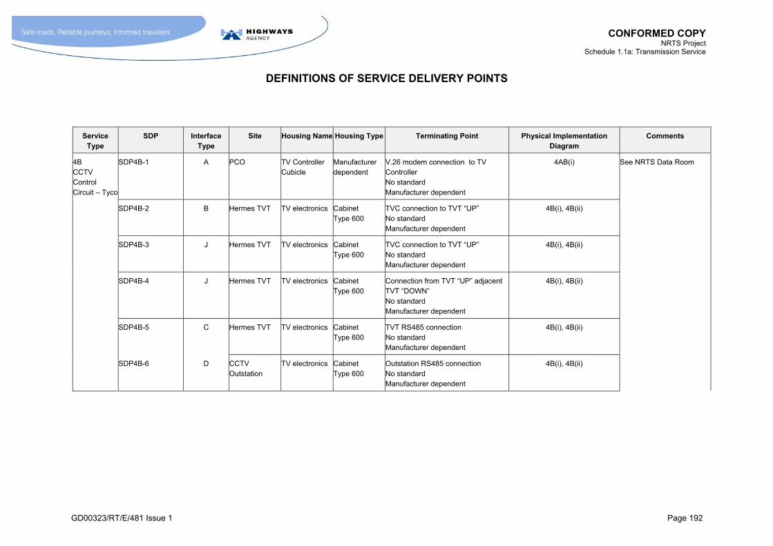
CONFORMED COPY NRTS Project
Schedule 1.1a: Transmission Service
DEFINITIONS OF SERVICE DELIVERY POINTS
GD00323/RT/E/481 Issue 1 Page 192
Service Type
SDP Interface Type
Site Housing Name Housing Type Terminating Point Physical Implementation Diagram
Comments
4B CCTV Control Circuit – Tyco
SDP4B-1 A PCO TV Controller Cubicle
Manufacturer dependent
V.26 modem connection to TV Controller No standard Manufacturer dependent
4AB(i)
SDP4B-2 B Hermes TVT TV electronics Cabinet Type 600
TVC connection to TVT “UP” No standard Manufacturer dependent
4B(i), 4B(ii)
SDP4B-3 J Hermes TVT TV electronics Cabinet Type 600
TVC connection to TVT “UP” No standard Manufacturer dependent
4B(i), 4B(ii)
SDP4B-4 J Hermes TVT TV electronics Cabinet Type 600
Connection from TVT “UP” adjacent TVT “DOWN” No standard Manufacturer dependent
4B(i), 4B(ii)
SDP4B-5 C Hermes TVT TV electronics Cabinet Type 600
TVT RS485 connection No standard Manufacturer dependent
4B(i), 4B(ii)
SDP4B-6 D CCTV Outstation
TV electronics Cabinet Type 600
Outstation RS485 connection No standard Manufacturer dependent
4B(i), 4B(ii)
See NRTS Data Room
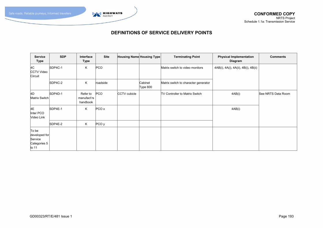
CONFORMED COPY NRTS Project
Schedule 1.1a: Transmission Service
DEFINITIONS OF SERVICE DELIVERY POINTS
GD00323/RT/E/481 Issue 1 Page 193
Service Type
SDP Interface Type
Site Housing Name Housing Type Terminating Point Physical Implementation Diagram
Comments
4C CCTV Video Circuit
SDP4C-1 K PCO Matrix switch to video monitors 4AB(i), 4A(i), 4A(ii), 4B(i), 4B(ii)
SDP4C-2 K roadside Cabinet Type 600
Matrix switch to character generator
4D Matrix Switch
SDP4D-1 Refer to manufact’rs handbook
PCO CCTV cubicle TV Controller to Matrix Switch 4AB(i)
4E Inter PCO Video Link
SDP4E-1 K PCO x 4AB(i)
SDP4E-2 K PCO y
See NRTS Data Room
To be developed for Service Categories 5 to 11
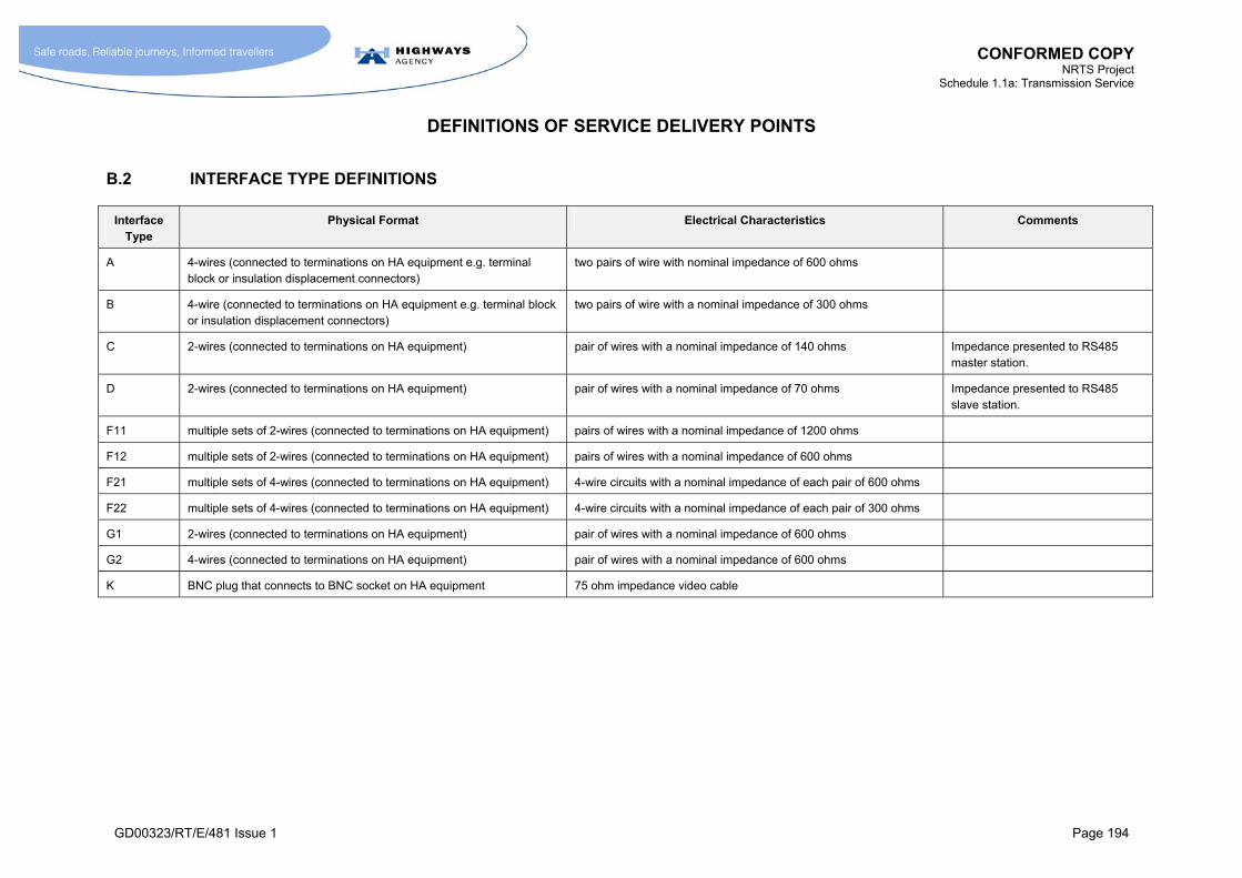
CONFORMED COPY NRTS Project
Schedule 1.1a: Transmission Service
DEFINITIONS OF SERVICE DELIVERY POINTS
GD00323/RT/E/481 Issue 1 Page 194
B.2 INTERFACE TYPE DEFINITIONS
Interface Type
Physical Format Electrical Characteristics Comments
A 4-wires (connected to terminations on HA equipment e.g. terminal block or insulation displacement connectors)
two pairs of wire with nominal impedance of 600 ohms
B 4-wire (connected to terminations on HA equipment e.g. terminal block or insulation displacement connectors)
two pairs of wire with a nominal impedance of 300 ohms
C 2-wires (connected to terminations on HA equipment) pair of wires with a nominal impedance of 140 ohms Impedance presented to RS485 master station.
D 2-wires (connected to terminations on HA equipment) pair of wires with a nominal impedance of 70 ohms Impedance presented to RS485 slave station.
F11 multiple sets of 2-wires (connected to terminations on HA equipment) pairs of wires with a nominal impedance of 1200 ohms
F12 multiple sets of 2-wires (connected to terminations on HA equipment) pairs of wires with a nominal impedance of 600 ohms
F21 multiple sets of 4-wires (connected to terminations on HA equipment) 4-wire circuits with a nominal impedance of each pair of 600 ohms
F22 multiple sets of 4-wires (connected to terminations on HA equipment) 4-wire circuits with a nominal impedance of each pair of 300 ohms
G1 2-wires (connected to terminations on HA equipment) pair of wires with a nominal impedance of 600 ohms
G2 4-wires (connected to terminations on HA equipment) pair of wires with a nominal impedance of 600 ohms
K BNC plug that connects to BNC socket on HA equipment 75 ohm impedance video cable

CONFORMED COPY NRTS Project
Schedule 1.1a: Transmission Service
DEFINITIONS OF SERVICE DELIVERY POINTS
GD00323/RT/E/481 Issue 1 Page 195
Interface Type
Physical Format Electrical Characteristics Comments
L1 TBA V.24/V28 Asynchronous 1.2kbps – 33kbps
L2 TBA V.24/V28 Synchronous 1.2kbps – 64kbps
M1 TBA X.21 Synchronous 64kbps – 2Mbps
N1 TBA G703 (with G704 frame structure) 64kbps – 2Mbps
N2 TBA G703 (with G742 frame structure) 8Mbps
N3 TBA G703 (with G751 frame structure) 34Mbps and 140Mbps
P1 TBA STM-1 (with G957 optical interface) 155Mbps
P2 TBA STM-4 (with G957 optical interface) 620Mbps
R1 TBA Ethernet 10Base –T 10Mbps
R2 TBA Ethernet 100Base-T 100Mbps
S1 TBA Optical Ethernet 10Base-FX 10Mbps optical interface
S2 TBA Optical Ethernet 100Base-FX 100Mbps optical interface

CONFORMED COPY NRTS Project
Schedule 1.1a: Transmission Service
GD00323/RT/E/481 Issue 1 Page 196
C ANNEX C
RULES FOR LOCATION OF ROADSIDE SDP FOR BESPOKE SERVICES
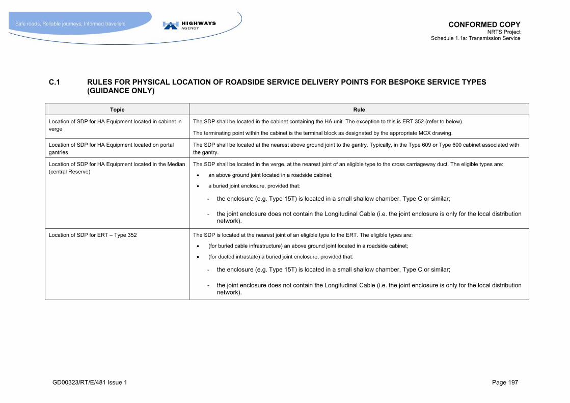
CONFORMED COPY NRTS Project
Schedule 1.1a: Transmission Service
GD00323/RT/E/481 Issue 1 Page 197
C.1 RULES FOR PHYSICAL LOCATION OF ROADSIDE SERVICE DELIVERY POINTS FOR BESPOKE SERVICE TYPES (GUIDANCE ONLY)
Topic Rule
Location of SDP for HA Equipment located in cabinet in verge
The SDP shall be located in the cabinet containing the HA unit. The exception to this is ERT 352 (refer to below).
The terminating point within the cabinet is the terminal block as designated by the appropriate MCX drawing.
Location of SDP for HA Equipment located on portal gantries
The SDP shall be located at the nearest above ground joint to the gantry. Typically, in the Type 609 or Type 600 cabinet associated with the gantry.
Location of SDP for HA Equipment located in the Median (central Reserve)
The SDP shall be located in the verge, at the nearest joint of an eligible type to the cross carriageway duct. The eligible types are:
an above ground joint located in a roadside cabinet;
a buried joint enclosure, provided that:
- the enclosure (e.g. Type 15T) is located in a small shallow chamber, Type C or similar;
- the joint enclosure does not contain the Longitudinal Cable (i.e. the joint enclosure is only for the local distribution network).
Location of SDP for ERT – Type 352 The SDP is located at the nearest joint of an eligible type to the ERT. The eligible types are:
(for buried cable infrastructure) an above ground joint located in a roadside cabinet;
(for ducted intrastate) a buried joint enclosure, provided that:
- the enclosure (e.g. Type 15T) is located in a small shallow chamber, Type C or similar;
- the joint enclosure does not contain the Longitudinal Cable (i.e. the joint enclosure is only for the local distribution network).

CONFORMED COPY NRTS Project
Schedule 1.1a: Transmission Service
RULES FOR PHYSICAL LOCATION OF ROADSIDE SERVICE DELIVERY POINTS FOR BESPOKE SERVICE TYPES
GD00323/RT/E/481 Issue 1 Page 198
Topic Rule
Location of SDP for ERT – Type 354 The SDP is always located in the ERT housing.
According to a programme defined by the HA, this arrangement will replace all instances of ERT Type 352.
Note: use of buried joint enclosures directly serving the longitudinal network
SDPs should not be located in any buried joint enclosure directly serving the longitudinal network. Where SDPs are located in a buried joint in the local network then this shall be considered an exception to the rule and should not be considered when developing any new service types.
Note: when SDP is separated from HA Equipment or Cross-Carriageway Duct by long run of cable
There are cases where a long distance of cable may exist between the HA equipment or cross—carriageway duct, where no suitable joint enclosures exist for locating the SDP.
In such cases, the HA may subsequently alter the arrangements such that a joint of an appropriate type is installed closer to the HA equipment. Where this occurs, the physical location of the SDP shall be regarded as having moved to this jointing enclosure.
Location of SDP within housing owned by HA Where the cabinet is owned by the HA (e.g. a cabinet containing a Standard Transponder), the SDP is the point at which the NRTS Co cable connects to the cable terminal block. The terminal block is the responsibility of the HA. NRTS Co is responsible for securing its cables into this terminal block.
Location of SDP within housing owned by NRTS Co This deals with the case where the cabinet/enclosure is owned by NRTS Co, but a connection is made with an HA cable. (For example, the case where the NRTS Co cabinet provides a connection to an HA cable that connects to HA equipment in the Median.) In such cases, NRTS Co shall provide “jumper wires” between the NRTS Co cable and the HA cable and the SDP is regarded as being the end of the jumper wires connected to the HA cable. The HA is responsible for the provision and maintenance of the HA cable. NRTS Co is responsible for the terminal block and for securing the HA cable into the terminal block.
Where new Service Type Instances are being provided Where new STIs are provided, the SDP will be regarded as being the appropriate terminating point in the HA equipment to which the SDP is connecting. Where this is not practical, for example, where the HA equipment is located in the Median, NRTS Co shall provide an appropriate jointing facility on the verge as close as is practical to the HA equipment. Where required NRTS Co shall modify the existing MCX installation drawings (part of the design rules) to reflect this requirement.

CONFORMED COPY NRTS Project
Schedule 1.1a: Transmission Service
GD00323/RT/E/481 Issue 1 Page 199
D ANNEX D
PHYSICAL IMPLEMENTATION DIAGRAMS (ROADSIDE)
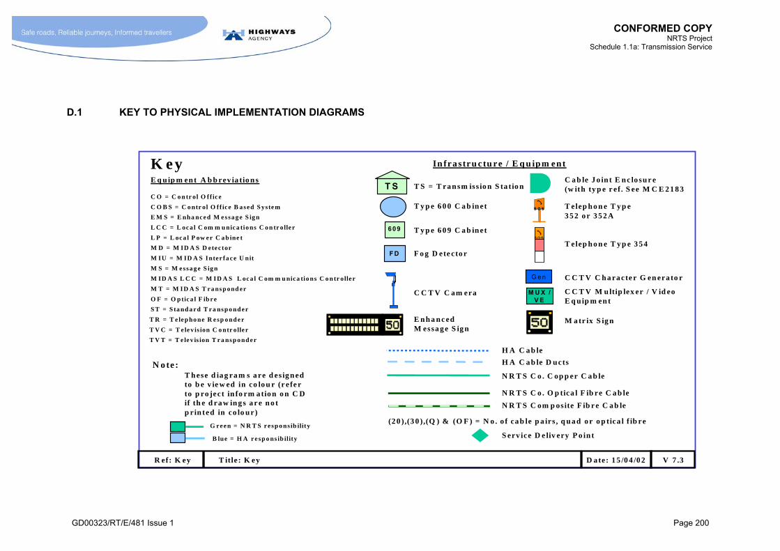
CONFORMED COPY
NRTS Project Schedule 1.1a: Transmission Service
GD00323/RT/E/481 Issue 1 Page 200
D.1 KEY TO PHYSICAL IMPLEMENTATION DIAGRAMS
K ey In fra stru ctu re / E q u ipm ent
T S T S = T ra n sm iss io n S ta tio n
S T = S ta nd a r d T r a nsp o nd e r
M D = M ID A S D ete c tor
T R = T e le p ho ne R e sp o nd e r
M T = M ID A S T r a nsp ond er
E q u ip m en t A b b rev ia tio n s
T y p e 6 0 0 C a b in et
609 T y p e 6 0 9 C a b in et
E M S = E nha nc e d M e ssa g e S ig n
C O B S = C o ntr ol O ff ic e B a sed S yste m
L P = L oc a l P ow e r C a b ine t
L C C = L oca l C om m u nic a tio ns C o n tr olle r
F D
C O = C o n tr ol O ff ic e
F o g D ete cto r
M S = M e ssa g e S ig n
C a b le J o in t E n c lo su r e(w ith ty p e r ef. S ee M C E 2 1 8 3
T V C = T e le v is ion C o ntr olle r
s os
sos
T elep h o n e T y p e 3 5 2 o r 3 5 2 A
T elep h o n e T y p e 3 5 4
C C T V C am era
T V T = T e le v is ion T r a nsp o nd e r
G e n
M U X / V E
C C T V C h a ra cte r G en era to r
C C T V M u ltip lex er / V id eo E q uip m en t
H A C a b le
H A C a b le D u cts
N R T S C o . C op p er C a b le
N R T S C o . O p tica l F ib re C a b le
S erv ice D e liv ery P o in t
O F = O p tic a l F ib r e
R ef: K ey T itle : K ey V 7 .3D a te: 1 5 /0 4 /0 2
AE n h a n c ed M essa g e S ig n
M a tr ix S ig n
M ID A S L C C = M ID A S L oc a l C om m u nica tio ns C o n tr olle r
G re e n = N R T S r esp o ns ib ility
B lue = H A r e sp o ns ib ility
N o te :
(2 0 ),(3 0 ),(Q ) & (O F ) = N o . o f ca b le p a irs , q u a d o r o p tica l f ib re
N R T S C om p osite F ib r e C a b le
T h ese d ia g ra m s a re d es ig n ed to b e v ie w ed in co lo u r (r efe r to p ro ject in fo rm a tio n o n C D if th e d ra w in g s a r e n o t p rin ted in co lo u r)
M IU = M ID A S Inter fa c e U nit
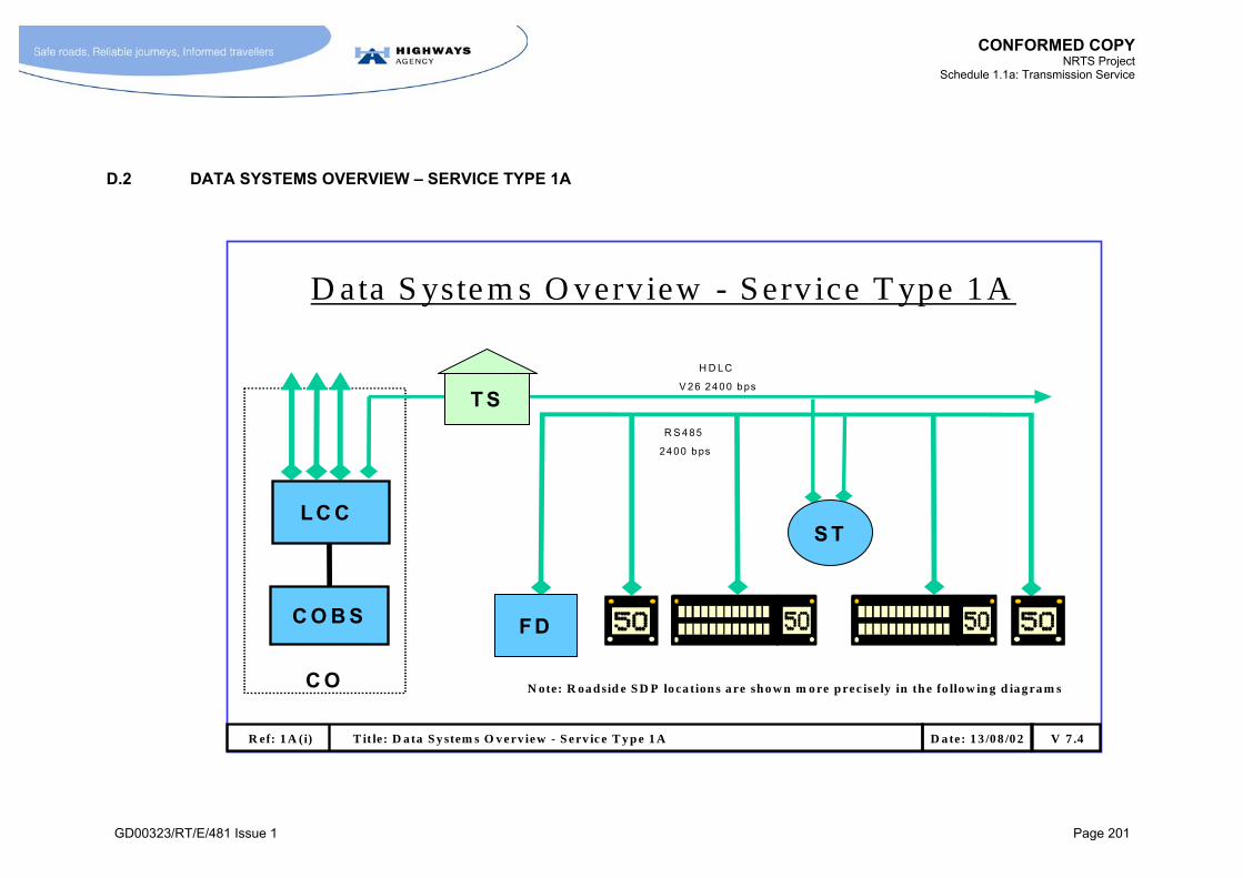
CONFORMED COPY
NRTS Project Schedule 1.1a: Transmission Service
GD00323/RT/E/481 Issue 1 Page 201
D.2 DATA SYSTEMS OVERVIEW – SERVICE TYPE 1A
C O
C O B S F D
S T
T S
D ata S yste m s O verv iew - S erv ice T ype 1A
H D LC
V 26 2400 bps
R S 485
2400 bps
A A
L C C
R ef: 1 A (i) T it le: D ata S y stem s O v erv iew - S erv ic e T y p e 1 A V 7 .4D a te: 1 3 /08 /0 2
N ote: R oa d sid e S D P lo ca tion s a re sh o w n m o re p rec ise ly in th e fo llo w in g d ia g ra m s
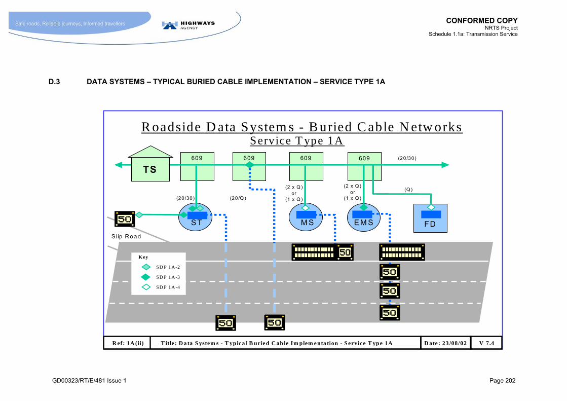
CONFORMED COPY
NRTS Project Schedule 1.1a: Transmission Service
GD00323/RT/E/481 Issue 1 Page 202
D.3 DATA SYSTEMS – TYPICAL BURIED CABLE IMPLEMENTATION – SERVICE TYPE 1A
R oadside D ata System s - B uried C able N etw orks
FDST M S
609 609609 609 (20/30)
EM S
A
(20/30) (20/Q )
(Q )(2 x Q )or
(1 x Q )
(2 x Q )or
(1 x Q )
TS
S lip R oad
R ef: 1A (ii) T itle : D a ta S ystem s - T ypic al B urie d C ab le Im plem e nta tion - S ervice T yp e 1A V 7.4D ate : 23 /08/02
K ey
SD P 1A-3
SD P 1A-4
SD P 1A-2
Service T ype 1A
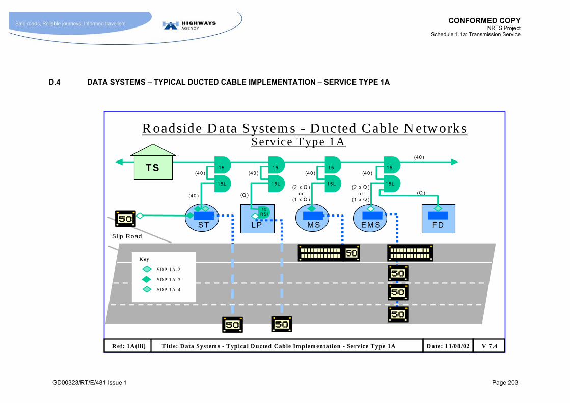
CONFORMED COPY
NRTS Project Schedule 1.1a: Transmission Service
GD00323/RT/E/481 Issue 1 Page 203
D.4 DATA SYSTEMS – TYPICAL DUCTED CABLE IMPLEMENTATION – SERVICE TYPE 1A
R oadside D ata System s - D ucted C able N etw orks
LP FDST M S EM S
(40 )
(40 )
(2 x Q )or
(1 x Q )(Q )
(2 x Q )or
(1 x Q )
(40 ) (40 ) (40 )
(40 )(Q )
15
15L
15
15L
15
15L
15
15L
A A
TS
Slip Road
15R S I
R ef: 1A (iii) T itle: D ata System s - Typical D ucted C able Im plem entation - Service Type 1A V 7.4D ate: 13/08/02
K ey
SD P 1A -3
SD P 1A -4
SD P 1A -2
Service Type 1A
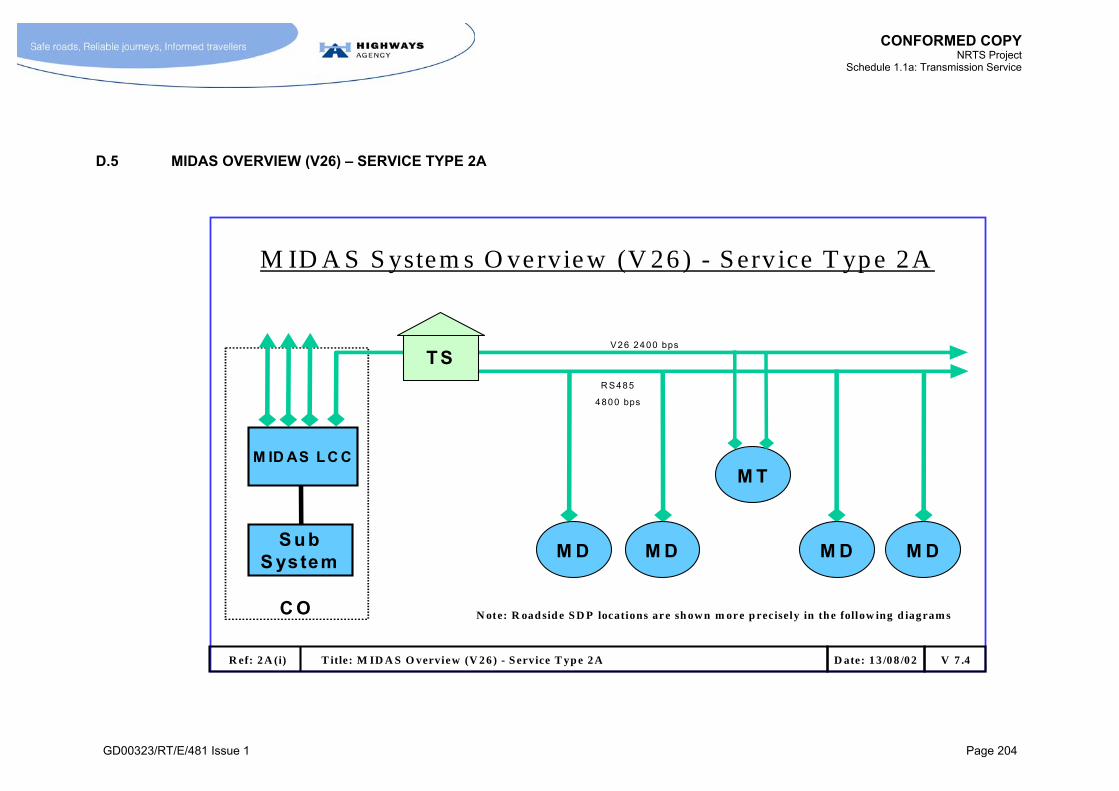
CONFORMED COPY
NRTS Project Schedule 1.1a: Transmission Service
GD00323/RT/E/481 Issue 1 Page 204
D.5 MIDAS OVERVIEW (V26) – SERVICE TYPE 2A
C O
S u bS ystem
M T
T S
M ID A S S ystem s O vervie w (V 26 ) - S erv ice T yp e 2A
V26 2400 bps
R S485
4800 bps
M D M D M D M D
M ID AS L C C
R ef: 2 A (i) T itle: M ID A S O verview (V 2 6 ) - S ervice T yp e 2 A V 7 .4D ate: 1 3 /0 8 /02
N ote: R oad sid e S D P locations are sh ow n m or e p recisely in th e follow ing d iagram s
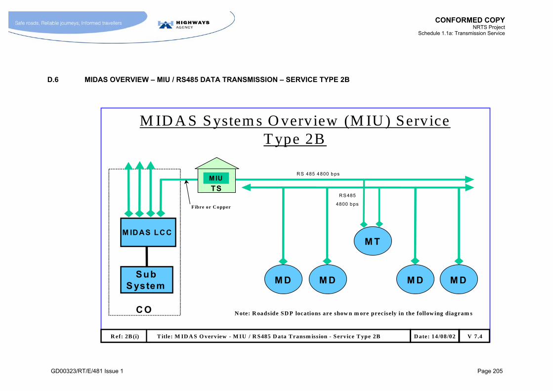
CONFORMED COPY
NRTS Project Schedule 1.1a: Transmission Service
GD00323/RT/E/481 Issue 1 Page 205
D.6 MIDAS OVERVIEW – MIU / RS485 DATA TRANSMISSION – SERVICE TYPE 2B
C O
SubS ystem
M T
M ID A S System s O verview (M IU ) Service T ype 2B
R S 485 4800 bps
R S485
4800 bps
M D M D M D M D
TS
M IDAS LCC
R ef: 2B (i) T itle: M ID A S O verview - M IU / R S485 D ata Transm ission - Service T ype 2B V 7.4D ate: 14/08/02
Fibre or C opper
M IU
N ote: R oadside SD P locations are show n m ore precisely in the follow ing diagram s
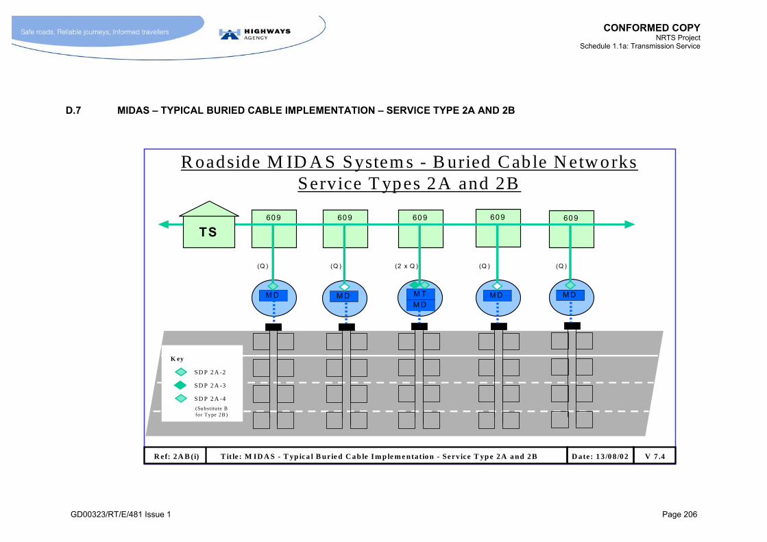
CONFORMED COPY
NRTS Project Schedule 1.1a: Transmission Service
GD00323/RT/E/481 Issue 1 Page 206
D.7 MIDAS – TYPICAL BURIED CABLE IMPLEMENTATION – SERVICE TYPE 2A AND 2B
R oadside M ID A S System s - B uried Cable N etworks Service T ypes 2A and 2B
(20/30)
(2 x Q )(Q )(Q ) (Q )
M D M D
609
M T
M D
(Q )
M D M D
609 60 9 609 60 9
TS
R ef: 2A B (i) T it le : M ID A S - T yp ica l B urie d C a b le I m p le m e ntatio n - Serv ice T yp e 2 A a nd 2 B V 7 .4D ate: 1 3 /0 8 /02
K ey
SD P 2 A -3
SD P 2 A -4
SD P 2 A -2
(Substitu te B for Type 2B )
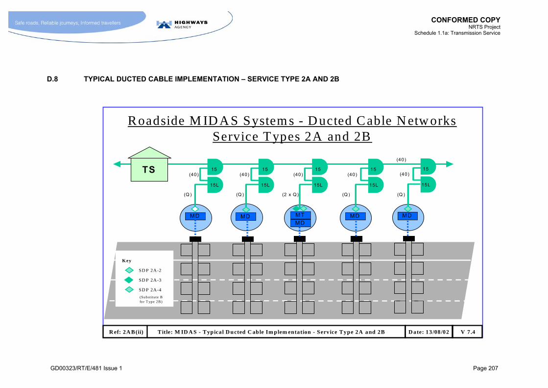
CONFORMED COPY
NRTS Project Schedule 1.1a: Transmission Service
GD00323/RT/E/481 Issue 1 Page 207
D.8 TYPICAL DUCTED CABLE IMPLEMENTATION – SERVICE TYPE 2A AND 2B
Roadside M ID A S System s - D ucted Cable N etw orks Service Types 2A and 2B
(40)
(2 x Q)(Q )
(40) (40) (40)
(Q ) (Q )
15
15L
15
15L
15
15L
TS
MD MD MT
MD
(40)
(Q )
15
15L
MD
(40)15
15L
MD
R ef: 2A B(ii) Title: M ID A S - Typical D ucted C able Im plem entation - Serv ice Type 2A and 2B V 7.4D ate: 13/08 /02
K ey
SD P 2A-3
SD P 2A-4
SD P 2A-2
(Substitu te B for T ype 2B)

CONFORMED COPY
NRTS Project Schedule 1.1a: Transmission Service
GD00323/RT/E/481 Issue 1 Page 208
D.9 EMERGENCY ROADSIDE TELEPHONE SYSTEM OVERVIEW – SERVICE TYPE 3A
T elephones - O verv iew - Serv ice T ype 3A
C O
TL C
TR
TS
so s
9 E R T M ax
so sso s so s
6 x O m nibus (D ata + S peech)
1 P air / T eleph one 1 P air / T eleph one
SectorSw itch
R ef: 3 A (i) T itle: E m ergen cy R oad side T elep hone S ystem O v erv iew - S erv ice T y pe 3A V 7 .4D ate: 1 3 /08 /0 2
O n e T L C per O m n ib u s C ircu it, i.e s ix .
9 E R T M ax
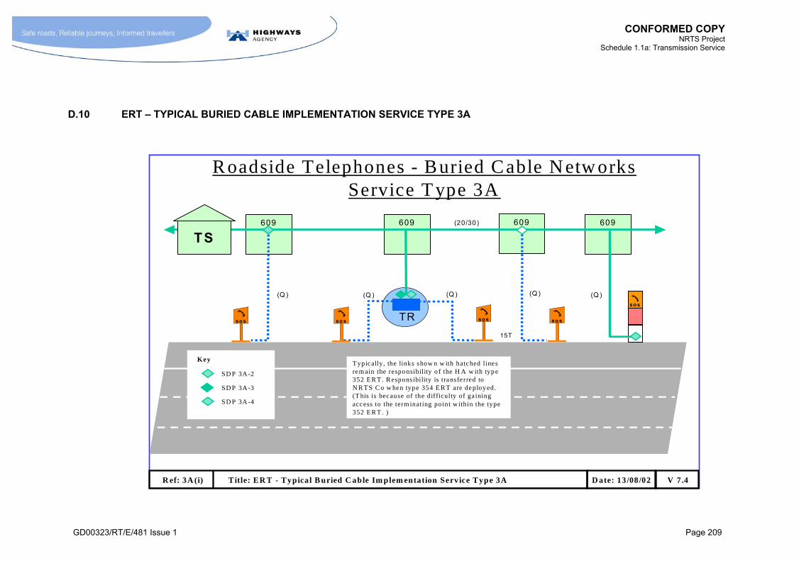
CONFORMED COPY
NRTS Project Schedule 1.1a: Transmission Service
GD00323/RT/E/481 Issue 1 Page 209
D.10 ERT – TYPICAL BURIED CABLE IMPLEMENTATION SERVICE TYPE 3A
609609 609
Roadside Telephones - Buried Cable N etw orks Service T ype 3A
(40)
TR
(Q )
15T
(Q )(Q )
609
TS
so s sos so sso s
(20/30)
sos
(Q ) (Q )
R ef: 3A (i) Title: ER T - Typical B uried C able Im plem entation Service Type 3A V 7.4D ate: 13/08/02
Key
SD P 3A-3
SD P 3A-4
SD P 3A-2
Typically, the links show n w ith hatched lines remain the respo nsibility o f the H A w ith typ e 352 ER T. R esponsibility is transfe rred to N R TS C o w hen type 354 ER T are deployed. (T his is because of the difficulty of ga ining access to the term inating point w ithin the type 352 ER T. )

CONFORMED COPY
NRTS Project Schedule 1.1a: Transmission Service
GD00323/RT/E/481 Issue 1 Page 210
D.11 ERT – TYPICAL DUCTED CABLE IMPLEMENTATION – SERVICE TYPE 3A
R oadside Telephones - D ucted C able N etw orks Service Type 3A
(40)
(40)15
15L
TR
(40)
(40)15
15L
TS(40)
15
15L
(Q )(Q )(Q)
15T
sos
(Q )
15T
sossos sos
15T15T 15T
sos
(Q )
R ef: 3A (ii) T itle: E R T - T ypical Ducted Cable Im plem entation - Service T ype 3A V 7.4D ate: 13/08/02
K ey
SD P 3A-3
SD P 3A-4
SD P 3A-2
Typica lly, the links show n w ith hatched lines remain the respo nsibility of the H A w ith type 352 ERT. Responsibility is transferred to N RTS Co w hen type 354 ERT are deplo yed. (Th is is because of the diff iculty of gaining access to the terminating point w ith in the type 352 ERT. )
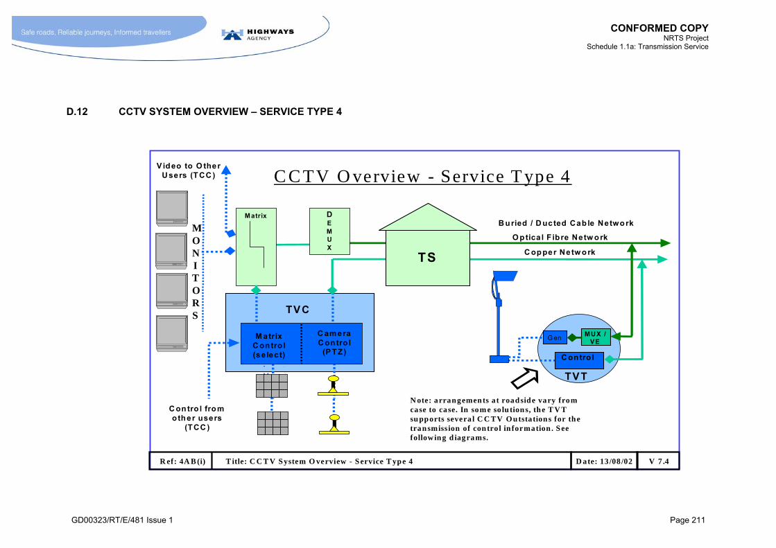
CONFORMED COPY
NRTS Project Schedule 1.1a: Transmission Service
GD00323/RT/E/481 Issue 1 Page 211
D.12 CCTV SYSTEM OVERVIEW – SERVICE TYPE 4
C C TV O verview - Service T ype 4
TS
TVT
B uried / D ucted Cab le NetworkDEMUX
V ideo to O therU sers (TCC )
C opper Netw ork
O ptica l F ibre Netw ork
MUX / VE
C ontro l
TVC
M atrixC ontro l(se lect)
C am eraC ontro l
(PTZ)
C ontro l from other users
(TCC )
G en
R ef: 4A B (i) T itle: C C T V System O verview - Service T ype 4 V 7 .4D ate: 13 /08 /02
Matrix
MONITORS
N ote: arrangements a t roadside vary from case to case. In som e so lu tions, the T V T su pports severa l C C TV Ou tstations for the transmission of contro l in formation . See following d iagrams.
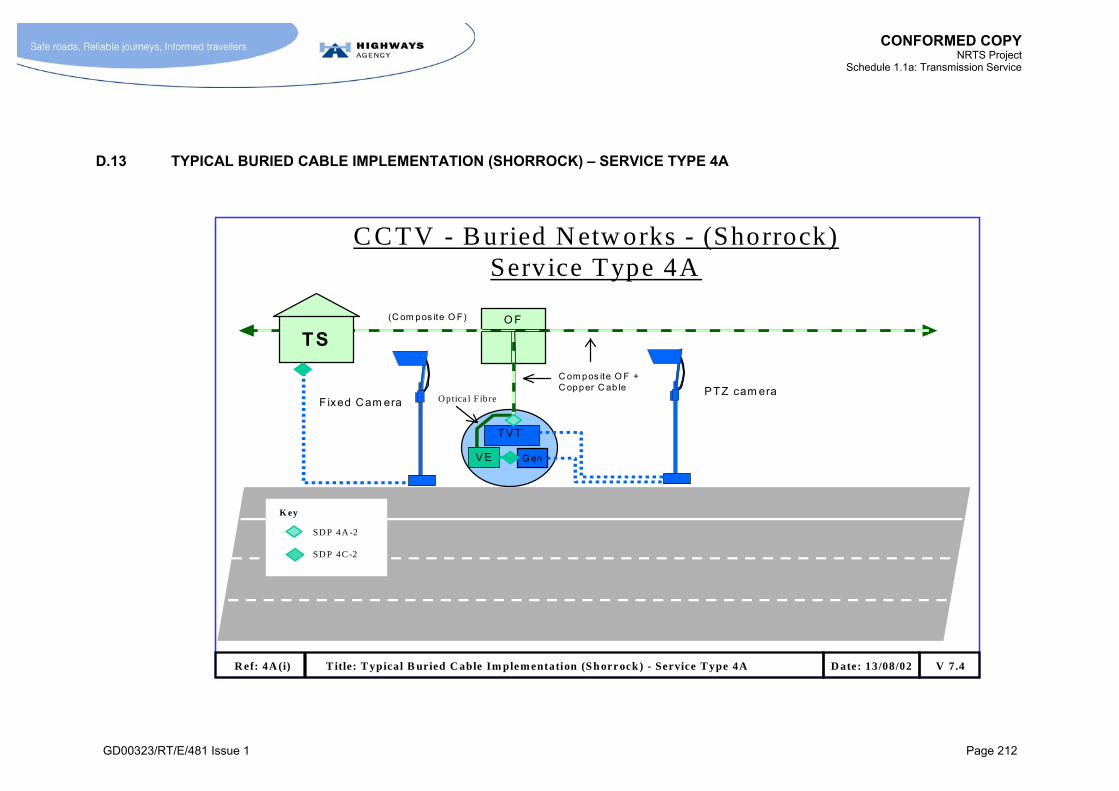
CONFORMED COPY
NRTS Project Schedule 1.1a: Transmission Service
GD00323/RT/E/481 Issue 1 Page 212
D.13 TYPICAL BURIED CABLE IMPLEMENTATION (SHORROCK) – SERVICE TYPE 4A
C C TV - B uried N etw orks - (Shorrock) Service Type 4A
O F(C om pos ite O F)
15O F
C om pos ite O F + C opper C ab le
TVT
G en
R ef: 4A (i) T itle: T ypical B uried C able Im plem entation (S h orrock ) - Service T ype 4A V 7.4D ate: 13/08/02
TS
VE
K ey
SD P 4A -2
SD P 4C-2
F ixed Cam era O ptica l F ibrePTZ cam era

CONFORMED COPY
NRTS Project Schedule 1.1a: Transmission Service
GD00323/RT/E/481 Issue 1 Page 213
D.14 TYPICAL DUCTED CABLE IMPLEMENTATION (SHORROCK) – SERVICE TYPE 4A
C C TV - D ucted N etw orks - (Shorrock)Service T ype 4A
(O F )
(40)
(3xQ )
O F
(O F)
15O F
TS
V E
(40)15
15L
(40)
TVT
G en
R ef: 4A (ii) T itle: Typica l D ucted C able Im plem entation (Shorrock - Service T ype 4A V 7 .4D ate: 13/08 /02
K ey
SD P 4A -2
SD P 4C-2

CONFORMED COPY
NRTS Project Schedule 1.1a: Transmission Service
GD00323/RT/E/481 Issue 1 Page 214
D.15 TYPICAL BURIED CABLE IMPLEMENTATION (TYCO) – SERVICE TYPE 4B
O FO F
C C T V - B uried N etw orks - T yco - Service T ype 4B
O F
C omposite O F+copper
cable
V ETV T
R ef: 4B (i) T itle : T ypic al B ur ied C ab le Im plem e nta tion (T yc o) - Service T ype 4B V 7.4D ate: 1 3/08 /02
K ey
S D P 4B-3
S D P 4B-4
S D P 4B-2
S D P 4C -2
TV T
1st 2nd
(30)(30)
TS
C opper pairsO ptical fibre
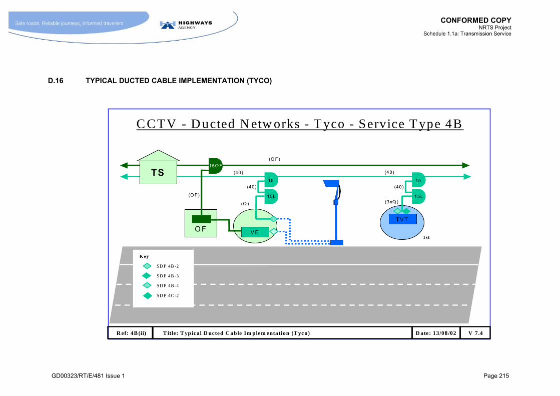
CONFORMED COPY
NRTS Project Schedule 1.1a: Transmission Service
GD00323/RT/E/481 Issue 1 Page 215
D.16 TYPICAL DUCTED CABLE IMPLEMENTATION (TYCO)
C C TV - D ucted N etw orks - T yco - Service T ype 4B
(O F)
(40)
(Q )
O F
(O F)
15O F
TS
V E
(40)15
15L
TV T
(40)15
15L(3xQ )
(40)
R ef: 4B (ii) T itle: T yp ical D ucted C able Im plem entation (T yco) V 7.4D ate: 13/08/02
1st
K ey
SD P 4B -3
SD P 4B -4
SD P 4B -2
SD P 4C -2

CONFORMED COPY NRTS Project
Schedule 1.1a: Transmission Service
GD00323/RT/E/481 Issue 1 Page 216
E ANNEX E
[NOT USED]

CONFORMED COPY NRTS Project
Schedule 1.1a: Transmission Service
GD00323/RT/E/481 Issue 1 Page 217
F ANNEX F
CRITICAL DESIGN RULES

CONFORMED COPY NRTS Project
Schedule 1.1a: Transmission Service
GD00323/RT/E/481 Issue 1 Page 218
F.1 CRITICAL DESIGN RULES
Relevant Service Type
Rule No.
Subject Bespoke Service Solution Specification Source 1A
1B
1C
2A
2B
2C
3A
4A
4B
4C
1 Ducts In deployment of new cable networks NRTS Co shall ensure that:
cables are contained in buried ducts;
the ducted network is sealed from gas and water;
the risk of rodent infestation is minimised;
the structure of the highway is not undermined;
the design is such that maintenance can be carried out
without digging up the road surface (including the hard
shoulder);
the means of construction and implementation is such that
there is minimal risk of other underground services being
damaged;
a detectable marking tape (or other suitable means of
warning parties digging near the cable of its location) is
employed;
the ducts should be appropriately colour coded in
accordance with the relevant Code of Practice and labelled
“Highways Agency”;
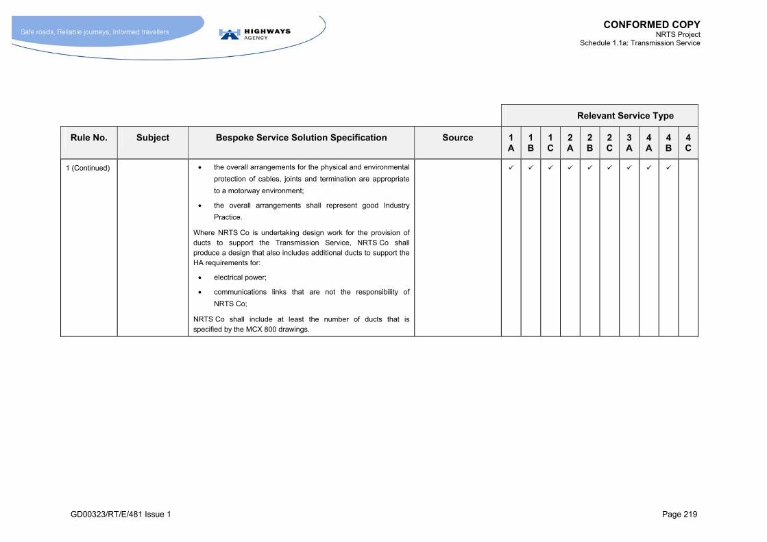
CONFORMED COPY NRTS Project
Schedule 1.1a: Transmission Service
GD00323/RT/E/481 Issue 1 Page 219
Relevant Service Type
Rule No. Subject Bespoke Service Solution Specification Source 1A
1B
1C
2A
2B
2C
3A
4A
4B
4C
1 (Continued) the overall arrangements for the physical and environmental
protection of cables, joints and termination are appropriate
to a motorway environment;
the overall arrangements shall represent good Industry
Practice.
Where NRTS Co is undertaking design work for the provision of ducts to support the Transmission Service, NRTS Co shall produce a design that also includes additional ducts to support the HA requirements for:
electrical power;
communications links that are not the responsibility of
NRTS Co;
NRTS Co shall include at least the number of ducts that is specified by the MCX 800 drawings.
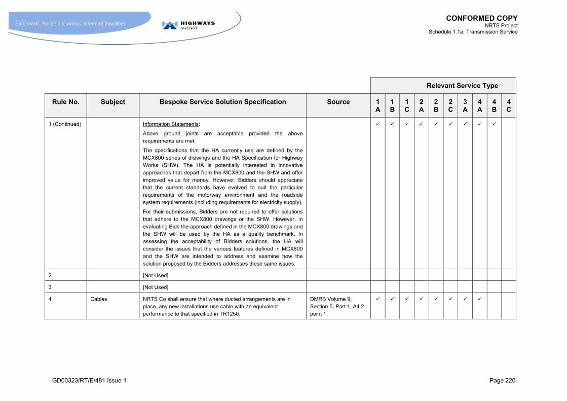
CONFORMED COPY NRTS Project
Schedule 1.1a: Transmission Service
GD00323/RT/E/481 Issue 1 Page 220
Relevant Service Type
Rule No. Subject Bespoke Service Solution Specification Source 1A
1B
1C
2A
2B
2C
3A
4A
4B
4C
1 (Continued) Information Statements:
Above ground joints are acceptable provided the above requirements are met.
The specifications that the HA currently use are defined by the MCX800 series of drawings and the HA Specification for Highway Works (SHW). The HA is potentially interested in innovative approaches that depart from the MCX800 and the SHW and offer improved value for money. However, Bidders should appreciate that the current standards have evolved to suit the particular requirements of the motorway environment and the roadside system requirements (including requirements for electricity supply).
For their submissions, Bidders are not required to offer solutions that adhere to the MCX800 drawings or the SHW. However, in evaluating Bids the approach defined in the MCX800 drawings and the SHW will be used by the HA as a quality benchmark. In assessing the acceptability of Bidders solutions, the HA will consider the issues that the various features defined in MCX800 and the SHW are intended to address and examine how the solution proposed by the Bidders addresses these same issues.
2 [Not Used]
3 [Not Used]
4 Cables NRTS Co shall ensure that where ducted arrangements are in place, any new installations use cable with an equivalent performance to that specified in TR1250.
DMRB Volume 9, Section 5, Part 1, A4.2 point 1.

CONFORMED COPY NRTS Project
Schedule 1.1a: Transmission Service
GD00323/RT/E/481 Issue 1 Page 221
Relevant Service Type
Rule No. Subject Bespoke Service Solution Specification Source 1A
1B
1C
2A
2B
2C
3A
4A
4B
4C
5 Cables NRTS Co shall ensure that where ducted arrangements are not in place, any new installation uses cable with an equivalent performance to that specified in TR2158.
DMRB Volume 9, Section 5, Part 1, A4.3 point 1.
6 Cables NRTS Co shall ensure that where ducted arrangements are in place any new deployment of optical fibre cable shall use non-armoured optical fibre cable with a performance equivalent to that specified in TR2151.
DMRB Volume 9, Section 5, Part 1, A4.2 point 9.
7 Cables NRTS Co shall ensure that where non-ducted arrangements are used any composite optical fibre/copper cable complies with TR2017.
DMRB Volume 9, Section 5, Part 1, A4.3 point 1.
8 Loading NRTS Co shall ensure that cable loading patterns are in accordance with the practices defined in the DMRB and MCL5502.
DMRB Volume 9, Section 4, Part 4, A5.3
DMRB Volume 9, Section 5, Part A5.5.
MCL5502
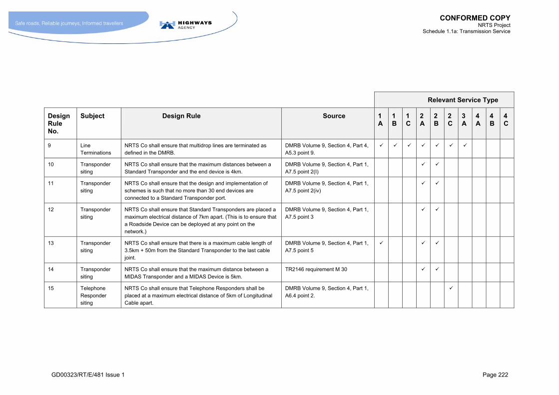
CONFORMED COPY NRTS Project
Schedule 1.1a: Transmission Service
GD00323/RT/E/481 Issue 1 Page 222
Relevant Service Type
Design Rule No.
Subject Design Rule Source 1A
1B
1C
2A
2B
2C
3A
4A
4B
4C
9 Line Terminations
NRTS Co shall ensure that multidrop lines are terminated as defined in the DMRB.
DMRB Volume 9, Section 4, Part 4, A5.3 point 9.
10 Transponder siting
NRTS Co shall ensure that the maximum distances between a Standard Transponder and the end device is 4km.
DMRB Volume 9, Section 4, Part 1, A7.5 point 2(I)
11 Transponder siting
NRTS Co shall ensure that the design and implementation of schemes is such that no more than 30 end devices are connected to a Standard Transponder port.
DMRB Volume 9, Section 4, Part 1, A7.5 point 2(iv)
12 Transponder siting
NRTS Co shall ensure that Standard Transponders are placed a maximum electrical distance of 7km apart. (This is to ensure that a Roadside Device can be deployed at any point on the network.)
DMRB Volume 9, Section 4, Part 1, A7.5 point 3
13 Transponder siting
NRTS Co shall ensure that there is a maximum cable length of 3.5km + 50m from the Standard Transponder to the last cable joint.
DMRB Volume 9, Section 4, Part 1, A7.5 point 5
14 Transponder siting
NRTS Co shall ensure that the maximum distance between a MIDAS Transponder and a MIDAS Device is 5km.
TR2146 requirement M 30
15 Telephone Responder siting
NRTS Co shall ensure that Telephone Responders shall be placed at a maximum electrical distance of 5km of Longitudinal Cable apart.
DMRB Volume 9, Section 4, Part 1, A6.4 point 2.

CONFORMED COPY NRTS Project
Schedule 1.1a: Transmission Service
GD00323/RT/E/481 Issue 1 Page 223
G ANNEX G
[NOT USED]


CONFORMED COPY NRTS Project
Schedule 1.1a: Transmission Service
GD00323/RT/E/481 Issue 1 Page 225
H ANNEX H
TRANSMISSION SERVICE PROVISIONING CAPABILITIES

CONFORMED COPY NRTS Project
Schedule 1.1a: Transmission Service
GD00323/RT/E/481 Issue 1 Page 226
H.1 TRANSMISSION SERVICE PROVISIONING CAPABILITIES
H.1.1 Service Provisioning Capabilities Rules and Enablements
H.1.1.1 M The HA shall be entitled to Call Off at Standard Prices STIs within limits defined by a system of Service Provisioning Capability (SPC) Rules and Enablement rules. These rules shall be as defined in Annex H.3.
H.1.1.2 M Service Provisioning Capabilities shall be classified as follows:
SPC ATMg Sections of the Project Road Network where the infrastructure required to support Active Traffic Management exists. This infrastructure includes copper cables and optical fibre cables.
SPC A Sections of the Project Road Network with infrastructure capable of supporting high density, high bandwidth services. This infrastructure includes copper cables and optical fibre cables.
SPC B Sections of the Project Road Network with infrastructure capable of supporting low bandwidth or low density services. This infrastructure includes copper cables.
SPC C All locations in England with no transmission service provision as designated under the NRTS Contract
SPC D Office locations including RCC and PCOs.
H.1.1.3 M Enablement shall be defined as the act of installing equipment that makes it possible to Provision Instances of particular Service Types. Typically, this involves the installation of common equipment that has the capability to support the Provisioning of a number of Instances of a Service Type on particular section of road.
H.1.1.4 M NRTS Co shall not be obliged to Provision an STI(s) by a Provisioning Date that is within the period covered by the longer of the associated Enablement Notice Period and the relevant Provisioning Notice Period, unless it expressly agrees to an earlier Provisioning Date.
H.1.1.5 M The Enablement Notice Period shall be 3 months.
H.1.1.6 M If application of the SPC Rules triggers the requirement both for an Enablement Notice Period and a Regrading Notice Period relating to the same Service Category and Locality, then these two Notice Periods shall run concurrently starting from the earlier of the start of the Enablement Notice Period or Regrading Notice Period and ending with the later of the end of the Enablement Notice Period or Regrading Notice Period.

CONFORMED COPY NRTS Project
Schedule 1.1a: Transmission Service
GD00323/RT/E/481 Issue 1 Page 227
H.1.2 Locality and the Local Access Limit
H.1.2.1 M The Locality shall be defined as the geographic extent of applicability of an SPC Rule.
H.1.2.2 M The Local Access Limit for SPC ATMg, SPC A, and SPC B shall be defined as a circle of radius 100 metres centred on the centre of the SDP. If this circle intersects at any point with the Longitudinal Network, then the SDP shall be deemed to be within the scope of the Standard Price, except in the cases of the following Service Types:
8RDCab;
10APCAb; or
10AFCab.
H.1.2.3 M For the following Service Types, the Standard Price shall apply where the SDP is located in a Genesys Cabinet or Transmission Station:
8RDCab;
10APCAb; or
10AFCab
In the case where 8RDCab is extended beyond the Genesys Cabinet, the price/metre of extending the SDP beyond the Genesys Cabinet shall be as stated in Schedule 30 Annex B, and the section between the Genesys Cabinet and the extended SDP is not required to be diverse routed.
In the case of Service Type 10APCab and Service Type 10AFCab, an equivalent Service Type outside of the Genesys Cabinet or Transmission Station shall be procured as Service Type 10AP or 10AF for which a 100m Local Access Limit applies.
H.1.2.4 M For all Service Types, except those identified in paragraph H.1.2.3, the price/metre of extending the SDP beyond the Local Access Limit shall be as stated in Schedule 30 Annex B.

CONFORMED COPY NRTS Project
Schedule 1.1a: Transmission Service
GD00323/RT/E/481 Issue 1 Page 228
H.1.3 Application of SPC Rules
H.1.3.1 M The SPC Rules shall only come into force for the following Service Categories at the earlier of the Transmission Full Service Start Date or the Generic Service Start Date for an area:
Service Category 8.
Service Category 9.
Service Category 10.
Service Category 11.
NRTS Co shall respond to requests for Hybrid Generic Service Types before the earlier of the Transmission Full Service Start Date or the Generic Service Start Date for the area in accordance with section 8 of Schedule 1.2.
H.1.3.2 M Regrading shall be the act of re-designating the SPC of a Locality, following the extension and equipping of the transmission network infrastructure to support a new level of Provision of STIs.
H.1.3.3 M NRTS Co shall undertake Regrading in response to a Regrading Task Authorisation issued by the HA.
H.1.3.4 [Not Used]
H.1.3.5 M The Regrading Notice Period shall be one year. All work shall be completed including Acceptance Tests by the expiry of the Regrading Notice Period.
H.1.3.6 M When a new Transmission Station is required as part of Regrade, NRTS Co shall propose a suitable location for agreement with the HA.
H.1.3.7 M When Regrading to SPC A, cables with at least the following capabilities shall be deployed: 40 copper pairs and 24 fibres.
H.1.3.8 M NRTS Co shall undertake Renewals of cables to at least the same standards as for an SPC A Regrade.

CONFORMED COPY NRTS Project
Schedule 1.1a: Transmission Service
GD00323/RT/E/481 Issue 1 Page 229
H.1.4 Regrading from SPC C
H.1.4.1 M Where the HA requires NRTS Co to Provision an STI in an SPC C Locality, the task shall be undertaken as:
a Designated link (delivered through the Designated Link mechanism) to connect a local island of SPC A or SPC B:
a island of SPC A or SPC B capability (delivered as an Ad Hoc Project) priced in accordance with paragraph H.1.4.5.
H.1.4.2 M NRTS Co shall define the SPC of the Locality served by the link as follows:
if the Locality is at an office building it shall be designated as SPC D;
else if any combination of the STIs in the Locality satisfies the SPC Rule for Regrading to SPC A for any of the relevant Service Categories or if the Service Category of the STI(s) in the Locality can only be provided in SPC A locations, it shall be designated as SPC A;
else it shall be designated as SPC B.
H.1.4.3 M NRTS Co shall record the Locality, the SPC designation and the applicable Service Categories as required for SPC tracking in accordance with the Manage Network process (Schedule 1.2 section 5.10).
H.1.4.4 M The geographic limit of the Locality (i.e. the island of SPC A or SPC B) shall be defined as the area physically covered (i.e. where a presence of the NRTS Transmission Network is established) by the Downstream end of the Designated Link. For instance:
if the link is a leased circuit to a single SDP, the limit will be a circle of a radius equal to the Local Access Limit centred on that SDP;
if the link was, say, to several SDPs grouped along a 5km section of trunk road which, as a result of the whole life costing, were connected via a new section of cable laid in the roadside verge, then the geographic limit would be 5km.
H.1.4.5 M NRTS Co shall Provision the STIs according to the Call-Off charges relevant to the SPC designation of the Locality, (i.e. the Standard SPC A Provisioning Charges if the Locality is SPC A and SPC B prices if the Locality is SPC B). The Designated Link shall cover only the link between the island of SPC A or SPC B and the rest of the NRTS Transmission Network.

CONFORMED COPY NRTS Project
Schedule 1.1a: Transmission Service
GD00323/RT/E/481 Issue 1 Page 230
H.2 DESIGNATED LINKS
H.2.1 Definitions of Designated Links
H.2.1.1 M A Designated Link shall be defined as a telecommunication link that connects localities of SPC ATMg, SPC A, SPC B, SPC D and forms an integral part of the NRTS Co network. Designated Links shall include:
links required to connect office locations (i.e. SPC D locations) into the NRTS Transmission Network (refer to annex section A.3.5);
links between an SPC D location (typically a Control Office) and an SPC C location (e.g. an end device located on a road where there is no existing transmission infrastructure);
links between one SPC D location and another SPC D location;
links required between the nearest point on the NRTS Transmission Network at an SPC A or “B” location to Downstream SDPs for STIs in locations where there is currently no core network infrastructure (i.e. SPC C locations) or where the particular Service Categories required are not supported by the core network infrastructure that does exist at the location, e.g. a CCTV service, Service Category 4, is required on a part of the motorway where there is only copper longitudinal cable (SPC B).
H.2.1.2 M NRTS Co carries the performance risk associated with Designated Links.
H.2.1.3 M See section H.2.3 for the definition of Designated Link scope and treatment of Designated Link costs.
H.2.2 Designated Link Procedure
H.2.2.1 M The Designated Link procedure described in this section covers the general steps NRTS Co shall undertake whenever it considers Designated Links in relation to:
Meeting the requirements for diverse routing (e.g. changing the specification of existing Designated Links that are used as diverse routes or adding new ones).
Changing the capacity or other characteristics of Designated Links to Control Offices and other SPC D locations because of changes in the STIs provided there.
Provisioning new STIs (requiring new Designated Links or increases in the capacity or other changes to existing Designated Links).
Removing STIs (requiring the Removal of Designated Links or decreases in the capacity or other changes to Designated Links that are still needed to support remaining STIs).
Any other changes to Designated Links (e.g. when a change of supplier becomes necessary, or moving a microwave point-to-point link to a different frequency to avoid interference).

CONFORMED COPY NRTS Project
Schedule 1.1a: Transmission Service
GD00323/RT/E/481 Issue 1 Page 231
H.2.2.2 M NRTS Co shall undertake all reasonable endeavours to ensure that the Designated Link solutions, both individually and collectively, represent best value for money for the HA. This requirement applies both to the renewal of existing Designated Links and the addition of new Designated Links.
H.2.2.3 M The rules for dimensioning Designated Links shall be as stated in section H.2.4.
H.2.2.4 M Whenever a Designated Link is required, NRTS Co shall provide the HA with an assessment of the range of potential solutions that are available for a Designated Link. The range of options shall include, for example:
a link leased from a public telecommunications operator;
a wireless link over a radio data network;
a point-to-point wireless link (microwave);
installation of a new cable;
other one-off arrangements to Provision an SDP of a Service Category that is not supported under the SPC Rules for SPC B or “A”, but which is located on a roadside which is actually SPC A or “B” (e.g. an IP service of Service Category 8 is required at the roadside before the relevant Generic Service Start Date or the Transmission Full Service Start Date has been reached).
H.2.2.5 M NRTS Co shall produce models of the whole life costs of the feasible options. These shall be based on the life-time costs of the underlying asset or service, not on the remaining years of the NRTS Co contract.
H.2.2.6 M Before proceeding with a new Designated Link, NRTS Co shall seek the consent of the HA. Such consent shall not be unreasonably withheld.
H.2.2.7 M Any installation work on Designated Links associated with the Provisioning of STIs shall be co-ordinated with, the Provisioning of STIs in accordance with the Provision Service process (Schedule 1.2 section 6.4) such that the installation of Designated Links does not adversely affect the “Provisioned” date by which the Provisioning of the STIs will be completed.
H.2.2.8 M NRTS Co shall take over responsibility for existing Designated Links from the Control Area Transmission Service Start Date for the area in which they are located.

CONFORMED COPY NRTS Project
Schedule 1.1a: Transmission Service
GD00323/RT/E/481 Issue 1 Page 232
H.2.3 Definition of Designated Link scope and treatment of Designated Link costs
H.2.3.1 M Where Designated Links are PTO leased lines, the following shall apply:
a) for PTO leased line Designated Links that: provide resilience in the Base Network (or otherwise link together sections of SPC A and/or SPC B) at the Transmission Full Service Start Date, NRTS Co shall only charge the HA the PTO invoice price plus the Designated Link Mark Up (the interface costs are included in the BSC);
b) for other PTO leased line Designated Links, NRTS Co shall only charge the HA the PTO invoice price plus the Designated Link Mark Up plus the cost of any additional interfacing equipment that is required.
H.2.3.2 [Not Used]
H.2.3.3 [Not Used]
H.2.3.4 M Where the Designated Link is provided by a “dedicated” optical fibre cable or copper cable, the scope of the Designated Link is the entire length of cable between:
the relevant interface to the NRTS Co equipment that provides the network node in the CO, TS, G-Cabinet or equivalent at one end of the cable;
the relevant interface to the NRTS Co equipment that provides the network node in the CO, TS, G-Cabinet or equivalent at the other end of the cable.
Notes:
a) where an optical fibre cable (or copper cable) forms part of the longitudinal network and is used to provide SPC A (or SPC B) capabilities, it is not regarded as a Designated Link;
b) the term “dedicated” means dedicated for the use of HA or NRTS Co; PTO leased lines that use optical fibre or copper cables are not regarded as “dedicated”.
H.2.3.5 M NRTS Co shall be responsible for the entirety of “dedicated” optical fibre cables or copper cables, including:
cables
ducts and related civil works
management and maintenance.
CONFORMED COPY NRTS Project
Schedule 1.1a: Transmission Service
GD00323/RT/E/481 Issue 1 Page 233
H.2.3.6 M Where a Designated Link is provided by a microwave system, the scope of the Designated Link shall include the entire microwave system and support arrangements for providing the link, including:
transceivers;
feeders, cables, antennas;
masts and towers;
power supplies;
repeater stations;
the link from the radio equipment to the network node in the RCC, PCO, TS, G-cabinet (or equivalent);
other radio transceiver equipment;
spares.
H.2.3.7 M NRTS Co shall be responsible for the management, operations and maintenance of all Designated Links excepting PTO leased links.
H.2.3.8 M The costs for all Designated Links other than PTO leased line Designated Links shall:
a) fall under the Base Service Charge where such Designated Links are identified in Annex J.
b) be charged as Ad Hoc Projects where new Designated Links are required.
H.2.3.9 M The cost PTO leased line Designated Links shall be charged to the HA as described paragraph H.2.3.1
H.2.4 Designated Link Rules
H.2.4.1 M Designated Links to SPC A or SPC ATMg shall be dimensioned to support the sum of the bandwidths required to support the STIs being transported over the Designated Link plus any network management traffic that might reasonably be assigned to the link. The bandwidth associated with each Service Type shall be as defined in Table I.1-1, or using the principles followed in Table I.1-1 to allow for framing overheads.
H.2.4.2 M For providing resilience to spurs of SPC A or SPC ATMg, the point of connection for a Designated Link to the spur shall be the last TS on the spur, or if there are G cabinets between the last TS and the end of the spur and the concentration of STIs at the G-Cabinets is such that the criterion in paragraph 15.14.8 would otherwise be broken, the last G-Cabinet in the span instead of the TS. Only one Designated Link is to be provided per spur of SPC A or SPC ATMg.
H.2.4.3 M Unless otherwise agreed with the HA, Designated Links shall not be used to provide a resilient path for the video services associated with Service Category 4 and Service Category 10, with the exception of the optical fibre links between RCCs and Transmission Stations.
H.2.4.4 M For SPC B roads the Designated link shall be an E1 leased service. Such Designated Links shall be provided:
at every 5th TS in the span;
at the TS at the end of a spur.

CONFORMED COPY NRTS Project
Schedule 1.1a: Transmission Service
GD00323/RT/E/481 Issue 1 Page 234
H.2.4.5 M The charge paid by the HA shall be based on normal grade rather than enhanced reliability PTO leased services with the exception of the case in paragraph H.2.4.5.1.
H.2.4.5.1. M Where the HA request that a Service Type Instance be deployed that:
has an SDP at a location that is isolated from the contiguous network of SPC A and SPC B infrastructure; and
is of a Service Type that is defined in this Schedule 1.1a as requiring diverse routing; and
where a diverse path is not provided by other means (e.g. a microwave radio link) or other PTO leased lines,
then NRTS Co may propose PTO leased line solutions that are diverse routed to the HA. Where the HA gives consent for such solutions, then the HA shall be charged a rate corresponding to the PTO services deployed.
H.2.4.6 M The selection of the type and bandwidth of circuit used for a Designated Link will be based on the criteria stipulated in paragraphs H.2.2.4 and H.2.2.5.

CONFORMED COPY NRTS Project
Schedule 1.1a: Transmission Service
GD00323/RT/E/481 Issue 1 Page 235
H.3 REQUIREMENTS FOR SPC AND ENABLEMENT RULES
H.3.1 General
H.3.1.1 M NRTS Co shall maintain a Registered Document “SPC Rules” that shall define:
the maximum number of STIs of various Service Types that can be supported in SPC A, SPC B and SPC ATMg sections of road;
the conditions that trigger the deployment of various “Enablements” and the number of STIs that can be supported by such Enablements;
any technical limits of the solution that would limit the number of STIs that can be supported by an Enablement; and
the range constraints associated with particular Service Types i.e. the distance between the Transmission Station (or cabinet) and the downstream SDP.
H.3.1.1.1. M The SPC and Enablement Rules Registered Document shall contain appropriate information on the equipment and infrastructure.
H.3.1.2 M NRTS Co shall ensure that the rules contained in the Registered Document “SPC Rules” comply with the requirements set out in this Annex H.
H.3.1.3 M NRTS Co shall adhere to the rules in the Registered Document “SPC Rules” in the implementation of their solution, unless otherwise agreed by both parties.
CONFORMED COPY NRTS Project
Schedule 1.1a: Transmission Service
GD00323/RT/E/481 Issue 1 Page 236
H.3.2 Passive Infrastructure Capabilities
H.3.2.1 M The maximum number of STIs that can be Called-Off in any section of road shall be limited by:
a) The quantity of copper pairs and optical fibres that the types of cables deployed in that section of road were manufactured to support. For example: 40 pair copper cable and a composite 12 pair copper plus 12 fibres = 52 copper pairs + 12 fibres.
b) The “pair consumption” and “fibre consumption” associated with the various Service Types and Enablements i.e. the number of copper pairs or optical fibres required by a particular Service Type or Enablement.
H.3.2.2 M NRTS Co shall ensure that the pair consumption and fibre consumption rules for the various Service Types are such that efficient use is made of the cable infrastructure.
H.3.2.3 M Where copper cables are not fully utilised at Take-On of a Service Area, NRTS Co shall be permitted to retain 2 pairs for maintenance purposes.
H.3.2.4 M It is noted that where composite cable (i.e. cable containing copper pairs and optical fibres) is deployed for the longitudinal infrastructure the points of access to the copper pairs in this cable are restricted to intervals of 1km. The HA shall permit the SPC and Enablement Rules to be reasonably qualified to take this constraint into account.
H.3.3 Technology Capabilities (Range Limitations)
H.3.3.1 M Where NRTS Co sets limits on the maximum distance between a TS (or G-cabinet or 600 cabinet) and the downstream SDP then, NRTS Co shall ensure that such limits reflect the maximum capabilities of the equipment, after making reasonable allowances for design tolerances.
H.3.4 Enablement Rules
H.3.4.1 M For meaning of the term Enablement, see paragraph H.1.1.3.
H.3.4.2 M The rules that apply to the various Enablements shall be as defined in Table H.3-1.
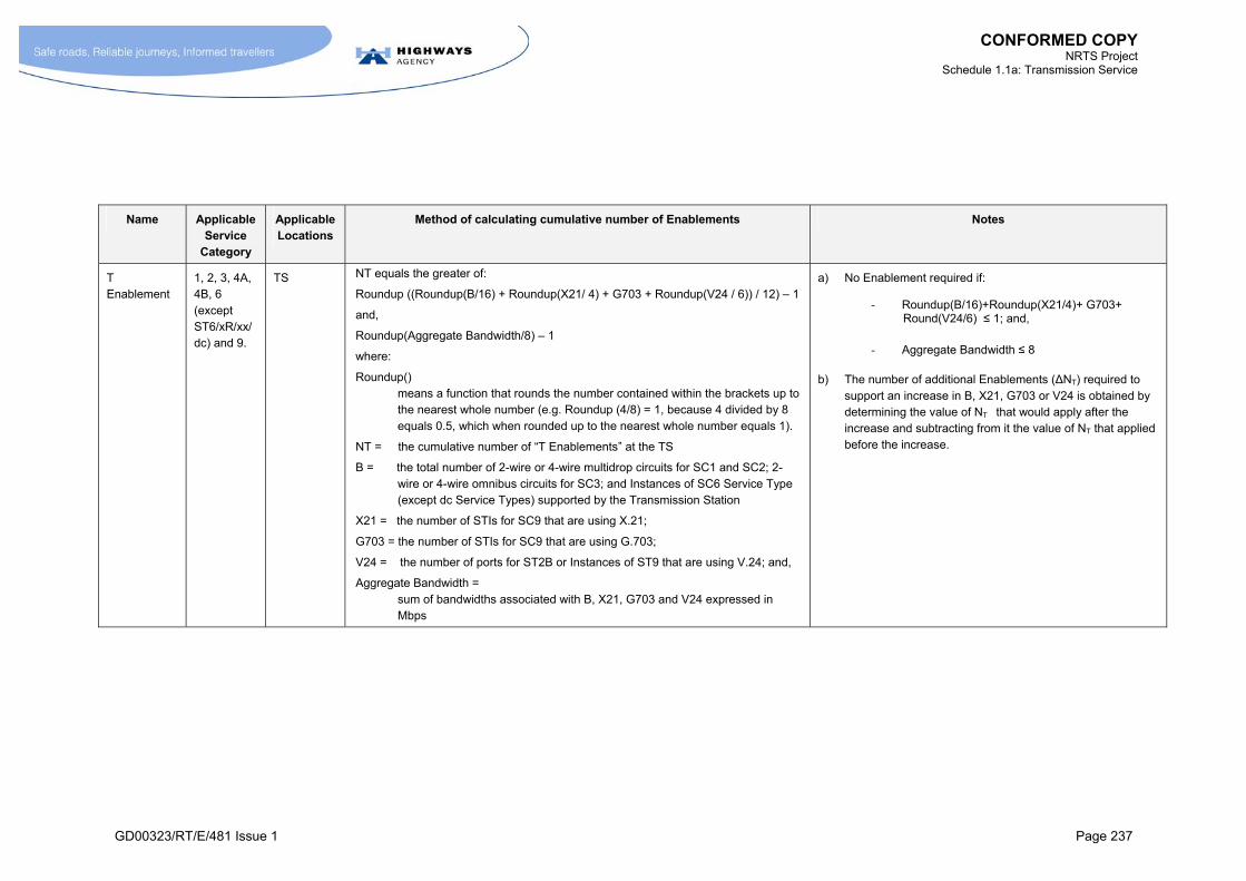
CONFORMED COPY NRTS Project
Schedule 1.1a: Transmission Service
GD00323/RT/E/481 Issue 1 Page 237
Name Applicable Service
Category
Applicable Locations
Method of calculating cumulative number of Enablements Notes
T Enablement
1, 2, 3, 4A, 4B, 6 (except ST6/xR/xx/dc) and 9.
TS NT equals the greater of:
Roundup ((Roundup(B/16) + Roundup(X21/ 4) + G703 + Roundup(V24 / 6)) / 12) – 1
and,
Roundup(Aggregate Bandwidth/8) – 1
where:
Roundup() means a function that rounds the number contained within the brackets up to the nearest whole number (e.g. Roundup (4/8) = 1, because 4 divided by 8 equals 0.5, which when rounded up to the nearest whole number equals 1).
NT = the cumulative number of “T Enablements” at the TS
B = the total number of 2-wire or 4-wire multidrop circuits for SC1 and SC2; 2-wire or 4-wire omnibus circuits for SC3; and Instances of SC6 Service Type (except dc Service Types) supported by the Transmission Station
X21 = the number of STIs for SC9 that are using X.21;
G703 = the number of STIs for SC9 that are using G.703;
V24 = the number of ports for ST2B or Instances of ST9 that are using V.24; and,
Aggregate Bandwidth = sum of bandwidths associated with B, X21, G703 and V24 expressed in Mbps
a) No Enablement required if:
- Roundup(B/16)+Roundup(X21/4)+ G703+ Round(V24/6) ≤ 1; and,
- Aggregate Bandwidth ≤ 8
b) The number of additional Enablements (ΔNT) required to support an increase in B, X21, G703 or V24 is obtained by determining the value of NT that would apply after the increase and subtracting from it the value of NT that applied before the increase.
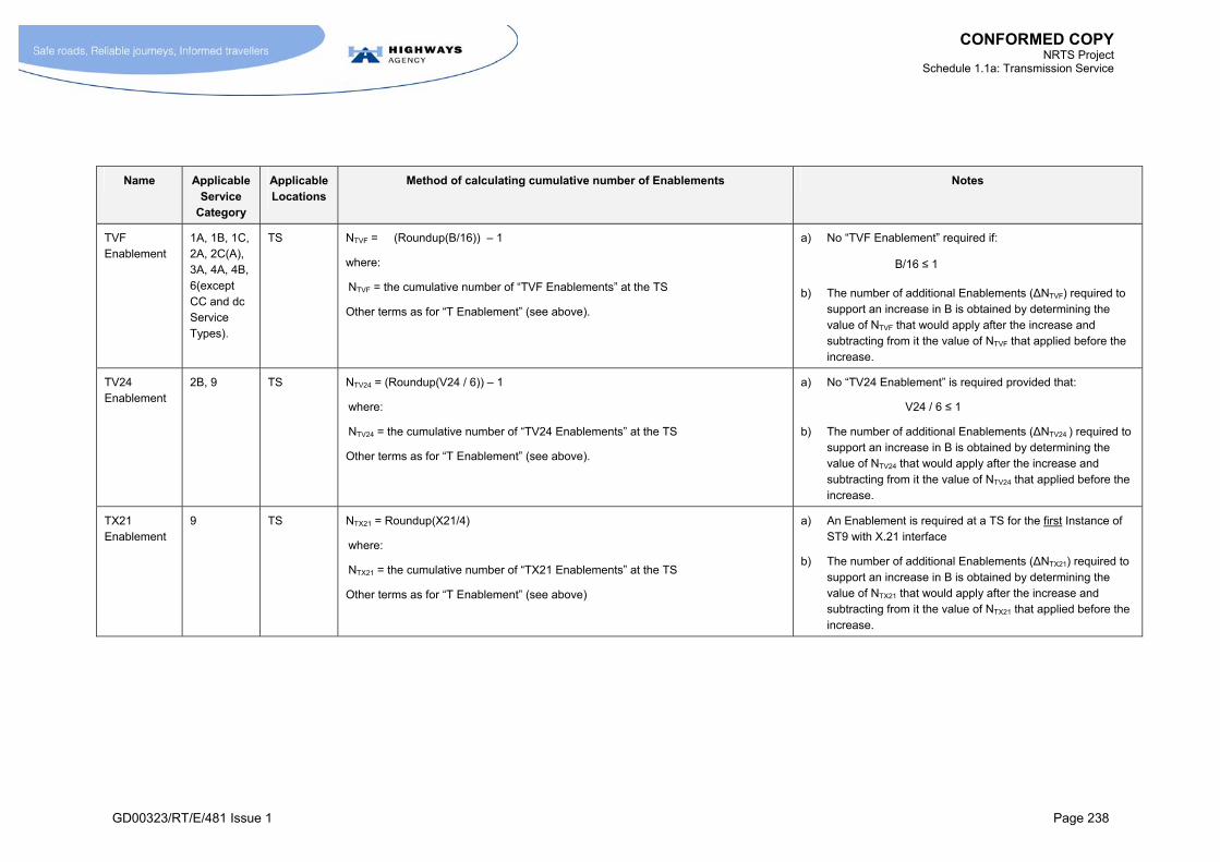
CONFORMED COPY NRTS Project
Schedule 1.1a: Transmission Service
GD00323/RT/E/481 Issue 1 Page 238
Name Applicable Service
Category
Applicable Locations
Method of calculating cumulative number of Enablements Notes
TVF Enablement
1A, 1B, 1C, 2A, 2C(A), 3A, 4A, 4B, 6(except CC and dc Service Types).
TS NTVF = (Roundup(B/16)) – 1
where:
NTVF = the cumulative number of “TVF Enablements” at the TS
Other terms as for “T Enablement” (see above).
a) No “TVF Enablement” required if:
B/16 ≤ 1
b) The number of additional Enablements (ΔNTVF) required to support an increase in B is obtained by determining the value of NTVF that would apply after the increase and subtracting from it the value of NTVF that applied before the increase.
TV24 Enablement
2B, 9 TS NTV24 = (Roundup(V24 / 6)) – 1
where:
NTV24 = the cumulative number of “TV24 Enablements” at the TS
Other terms as for “T Enablement” (see above).
a) No “TV24 Enablement” is required provided that:
V24 / 6 ≤ 1
b) The number of additional Enablements (ΔNTV24 ) required to support an increase in B is obtained by determining the value of NTV24 that would apply after the increase and subtracting from it the value of NTV24 that applied before the increase.
TX21 Enablement
9 TS NTX21 = Roundup(X21/4)
where:
NTX21 = the cumulative number of “TX21 Enablements” at the TS
Other terms as for “T Enablement” (see above)
a) An Enablement is required at a TS for the first Instance of ST9 with X.21 interface
b) The number of additional Enablements (ΔNTX21) required to support an increase in B is obtained by determining the value of NTX21 that would apply after the increase and subtracting from it the value of NTX21 that applied before the increase.
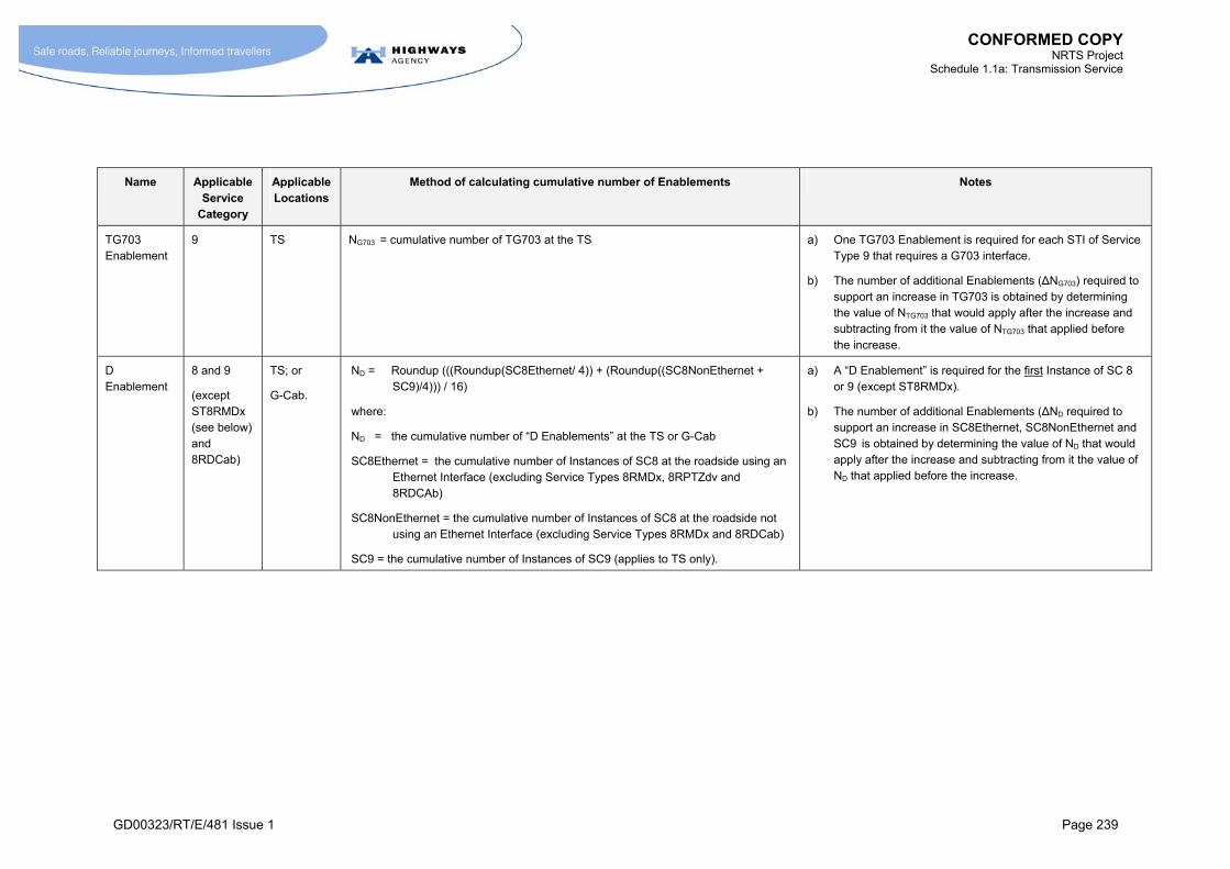
CONFORMED COPY NRTS Project
Schedule 1.1a: Transmission Service
GD00323/RT/E/481 Issue 1 Page 239
Name Applicable Service
Category
Applicable Locations
Method of calculating cumulative number of Enablements Notes
TG703 Enablement
9 TS NG703 = cumulative number of TG703 at the TS a) One TG703 Enablement is required for each STI of Service Type 9 that requires a G703 interface.
b) The number of additional Enablements (ΔNG703) required to support an increase in TG703 is obtained by determining the value of NTG703 that would apply after the increase and subtracting from it the value of NTG703 that applied before the increase.
D Enablement
8 and 9
(except ST8RMDx (see below) and 8RDCab)
TS; or
G-Cab.
ND = Roundup (((Roundup(SC8Ethernet/ 4)) + (Roundup((SC8NonEthernet + SC9)/4))) / 16)
where:
ND = the cumulative number of “D Enablements” at the TS or G-Cab
SC8Ethernet = the cumulative number of Instances of SC8 at the roadside using an Ethernet Interface (excluding Service Types 8RMDx, 8RPTZdv and 8RDCAb)
SC8NonEthernet = the cumulative number of Instances of SC8 at the roadside not using an Ethernet Interface (excluding Service Types 8RMDx and 8RDCab)
SC9 = the cumulative number of Instances of SC9 (applies to TS only).
a) A “D Enablement” is required for the first Instance of SC 8 or 9 (except ST8RMDx).
b) The number of additional Enablements (ΔND required to support an increase in SC8Ethernet, SC8NonEthernet and SC9 is obtained by determining the value of ND that would apply after the increase and subtracting from it the value of ND that applied before the increase.

CONFORMED COPY NRTS Project
Schedule 1.1a: Transmission Service
GD00323/RT/E/481 Issue 1 Page 240
Name Applicable Service
Category
Applicable Locations
Method of calculating cumulative number of Enablements Notes
Serial Enablement
8 TS; or
G-Cab
Nserial = Roundup (Xserial / 14 )
where:
Nserial = the cumulative number of “Serial Enablements” at the TS or G-Cabinet
Xserial = the cumulative number of STIs of SC8 that utilise a V.24 or X.21 interface
The function Roundup() is as defined for T Enablement
a) A “Serial Enablement” is required for the first Instance of SC 8 that uses either an X.21 or V.24 interface.
b) The number of additional Enablements (ΔNserial required to support an increase in Xserial is obtained by determining the value of Nserial that would apply after the increase and subtracting from it the value of Nserial that applied before the increase.
[ST8RMD Enablement]12
[ST8RMD] TS or G-Cab
[NST8RMD equals the greater of either:
Roundup (M / 64 ); or
Roundup (Mbandwidth)/2
where:
NST8RMD=
the cumulative number ST8RMD Enablements to support a TS to TS, TS to G-Cab, or G-Cab to G-Cab span
M = the number of STIs of ST8RMD; and
Mbandwidth =
the sum of the Access Line Band of all the ST8RMD STIs supported by the Enablement(s) in Mbps.
The function Roundup() is as defined for T Enablement]
a) The first STI on a span triggers an ST8RMD Enablement.
b) The number of additional Enablements (ΔNST8RMD) required to support an increase in M is obtained by determining the value of NST8RMD that would apply after the increase and subtracting from it the value of NST8RMD that applied before the increase.
12 If this Enablement is not fully defined by Execution Date, these table entries to be removed and replaced with the following statement. “This Enablement to be fully defined by Step 1 (see Schedule 1.2).”
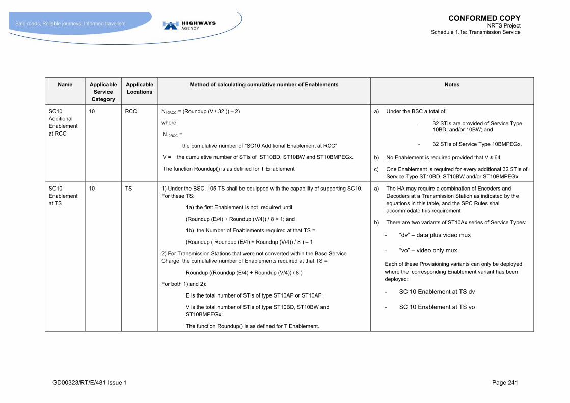
CONFORMED COPY NRTS Project
Schedule 1.1a: Transmission Service
GD00323/RT/E/481 Issue 1 Page 241
Name Applicable Service
Category
Applicable Locations
Method of calculating cumulative number of Enablements Notes
SC10 Additional Enablement at RCC
10 RCC N10RCC = (Roundup (V / 32 )) – 2)
where:
N10RCC =
the cumulative number of “SC10 Additional Enablement at RCC”
V = the cumulative number of STIs of ST10BD, ST10BW and ST10BMPEGx.
The function Roundup() is as defined for T Enablement
a) Under the BSC a total of:
- 32 STIs are provided of Service Type 10BD; and/or 10BW; and
- 32 STIs of Service Type 10BMPEGx.
b) No Enablement is required provided that V ≤ 64
c) One Enablement is required for every additional 32 STIs of Service Type ST10BD, ST10BW and/or ST10BMPEGx.
SC10 Enablement at TS
10 TS 1) Under the BSC, 105 TS shall be equipped with the capability of supporting SC10. For these TS:
1a) the first Enablement is not required until
(Roundup (E/4) + Roundup (V/4)) / 8 > 1; and
1b) the Number of Enablements required at that TS =
(Roundup ( Roundup (E/4) + Roundup (V/4)) / 8 ) – 1
2) For Transmission Stations that were not converted within the Base Service Charge, the cumulative number of Enablements required at that TS =
Roundup ((Roundup (E/4) + Roundup (V/4)) / 8 )
For both 1) and 2):
E is the total number of STIs of type ST10AP or ST10AF;
V is the total number of STIs of type ST10BD, ST10BW and ST10BMPEGx;
The function Roundup() is as defined for T Enablement.
a) The HA may require a combination of Encoders and Decoders at a Transmission Station as indicated by the equations in this table, and the SPC Rules shall accommodate this requirement
b) There are two variants of ST10Ax series of Service Types:
- “dv” – data plus video mux
- “vo” – video only mux
Each of these Provisioning variants can only be deployed where the corresponding Enablement variant has been deployed:
- SC 10 Enablement at TS dv
- SC 10 Enablement at TS vo
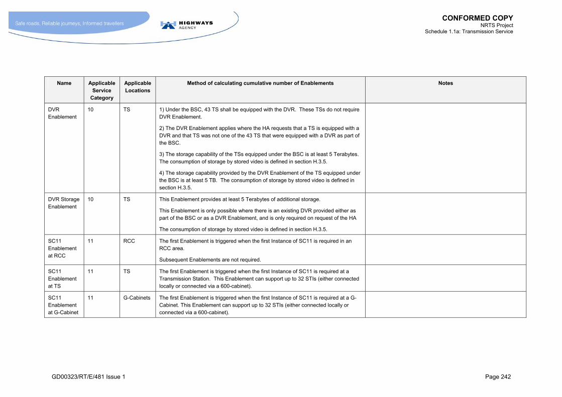
CONFORMED COPY NRTS Project
Schedule 1.1a: Transmission Service
GD00323/RT/E/481 Issue 1 Page 242
Name Applicable Service
Category
Applicable Locations
Method of calculating cumulative number of Enablements Notes
DVR Enablement
10 TS 1) Under the BSC, 43 TS shall be equipped with the DVR. These TSs do not require DVR Enablement.
2) The DVR Enablement applies where the HA requests that a TS is equipped with a DVR and that TS was not one of the 43 TS that were equipped with a DVR as part of the BSC.
3) The storage capability of the TSs equipped under the BSC is at least 5 Terabytes. The consumption of storage by stored video is defined in section H.3.5.
4) The storage capability provided by the DVR Enablement of the TS equipped under the BSC is at least 5 TB. The consumption of storage by stored video is defined in section H.3.5.
DVR Storage Enablement
10 TS This Enablement provides at least 5 Terabytes of additional storage.
This Enablement is only possible where there is an existing DVR provided either as part of the BSC or as a DVR Enablement, and is only required on request of the HA
The consumption of storage by stored video is defined in section H.3.5.
SC11 Enablement at RCC
11 RCC The first Enablement is triggered when the first Instance of SC11 is required in an RCC area.
Subsequent Enablements are not required.
SC11 Enablement at TS
11 TS The first Enablement is triggered when the first Instance of SC11 is required at a Transmission Station. This Enablement can support up to 32 STIs (either connected locally or connected via a 600-cabinet).
SC11 Enablement at G-Cabinet
11 G-Cabinets The first Enablement is triggered when the first Instance of SC11 is required at a G-Cabinet. This Enablement can support up to 32 STIs (either connected locally or connected via a 600-cabinet).
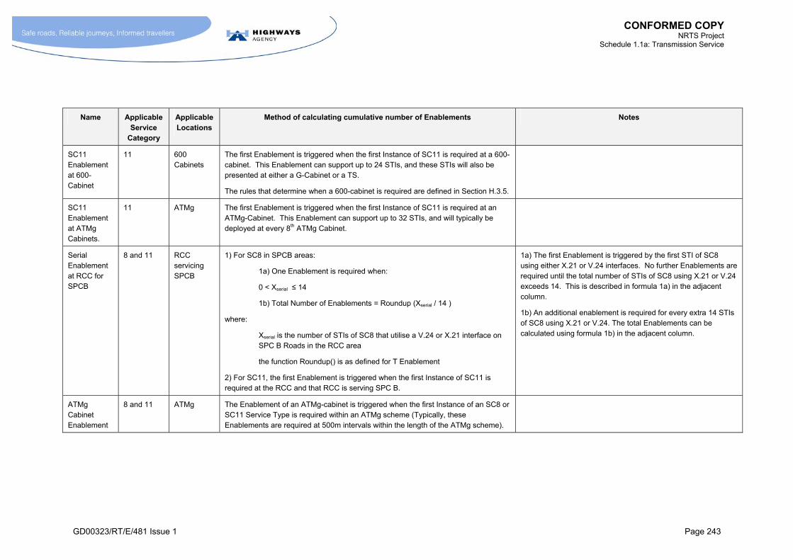
CONFORMED COPY NRTS Project
Schedule 1.1a: Transmission Service
GD00323/RT/E/481 Issue 1 Page 243
Name Applicable Service
Category
Applicable Locations
Method of calculating cumulative number of Enablements Notes
SC11 Enablement at 600-Cabinet
11 600 Cabinets
The first Enablement is triggered when the first Instance of SC11 is required at a 600-cabinet. This Enablement can support up to 24 STIs, and these STIs will also be presented at either a G-Cabinet or a TS.
The rules that determine when a 600-cabinet is required are defined in Section H.3.5.
SC11 Enablement at ATMg Cabinets.
11 ATMg The first Enablement is triggered when the first Instance of SC11 is required at an ATMg-Cabinet. This Enablement can support up to 32 STIs, and will typically be deployed at every 8th ATMg Cabinet.
Serial Enablement at RCC for SPCB
8 and 11 RCC servicing SPCB
1) For SC8 in SPCB areas:
1a) One Enablement is required when:
0 < Xserial ≤ 14
1b) Total Number of Enablements = Roundup (Xserial / 14 )
where:
Xserial is the number of STIs of SC8 that utilise a V.24 or X.21 interface on SPC B Roads in the RCC area
the function Roundup() is as defined for T Enablement
2) For SC11, the first Enablement is triggered when the first Instance of SC11 is required at the RCC and that RCC is serving SPC B.
1a) The first Enablement is triggered by the first STI of SC8 using either X.21 or V.24 interfaces. No further Enablements are required until the total number of STIs of SC8 using X.21 or V.24 exceeds 14. This is described in formula 1a) in the adjacent column.
1b) An additional enablement is required for every extra 14 STIs of SC8 using X.21 or V.24. The total Enablements can be calculated using formula 1b) in the adjacent column.
ATMg Cabinet Enablement
8 and 11 ATMg The Enablement of an ATMg-cabinet is triggered when the first Instance of an SC8 or SC11 Service Type is required within an ATMg scheme (Typically, these Enablements are required at 500m intervals within the length of the ATMg scheme).
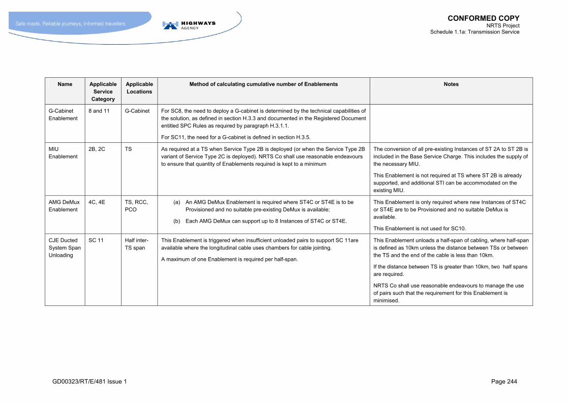
CONFORMED COPY NRTS Project
Schedule 1.1a: Transmission Service
GD00323/RT/E/481 Issue 1 Page 244
Name Applicable Service
Category
Applicable Locations
Method of calculating cumulative number of Enablements Notes
G-Cabinet Enablement
8 and 11 G-Cabinet For SC8, the need to deploy a G-cabinet is determined by the technical capabilities of the solution, as defined in section H.3.3 and documented in the Registered Document entitled SPC Rules as required by paragraph H.3.1.1.
For SC11, the need for a G-cabinet is defined in section H.3.5.
MIU Enablement
2B, 2C TS As required at a TS when Service Type 2B is deployed (or when the Service Type 2B variant of Service Type 2C is deployed). NRTS Co shall use reasonable endeavours to ensure that quantity of Enablements required is kept to a minimum
The conversion of all pre-existing Instances of ST 2A to ST 2B is included in the Base Service Charge. This includes the supply of the necessary MIU.
This Enablement is not required at TS where ST 2B is already supported, and additional STI can be accommodated on the existing MIU.
AMG DeMux Enablement
4C, 4E TS, RCC, PCO
(a) An AMG DeMux Enablement is required where ST4C or ST4E is to be Provisioned and no suitable pre-existing DeMux is available;
(b) Each AMG DeMux can support up to 8 Instances of ST4C or ST4E.
This Enablement is only required where new Instances of ST4C or ST4E are to be Provisioned and no suitable DeMux is available.
This Enablement is not used for SC10.
CJE Ducted System Span Unloading
SC 11 Half inter-TS span
This Enablement is triggered when insufficient unloaded pairs to support SC 11are available where the longitudinal cable uses chambers for cable jointing.
A maximum of one Enablement is required per half-span.
This Enablement unloads a half-span of cabling, where half-span is defined as 10km unless the distance between TSs or between the TS and the end of the cable is less than 10km.
If the distance between TS is greater than 10km, two half spans are required.
NRTS Co shall use reasonable endeavours to manage the use of pairs such that the requirement for this Enablement is minimised.
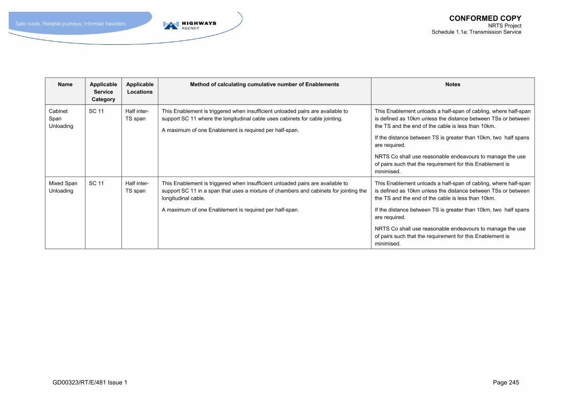
CONFORMED COPY NRTS Project
Schedule 1.1a: Transmission Service
GD00323/RT/E/481 Issue 1 Page 245
Name Applicable Service
Category
Applicable Locations
Method of calculating cumulative number of Enablements Notes
Cabinet Span Unloading
SC 11 Half inter-TS span
This Enablement is triggered when insufficient unloaded pairs are available to support SC 11 where the longitudinal cable uses cabinets for cable jointing.
A maximum of one Enablement is required per half-span.
This Enablement unloads a half-span of cabling, where half-span is defined as 10km unless the distance between TSs or between the TS and the end of the cable is less than 10km.
If the distance between TS is greater than 10km, two half spans are required.
NRTS Co shall use reasonable endeavours to manage the use of pairs such that the requirement for this Enablement is minimised.
Mixed Span Unloading
SC 11 Half inter-TS span
This Enablement is triggered when insufficient unloaded pairs are available to support SC 11 in a span that uses a mixture of chambers and cabinets for jointing the longitudinal cable.
A maximum of one Enablement is required per half-span.
This Enablement unloads a half-span of cabling, where half-span is defined as 10km unless the distance between TSs or between the TS and the end of the cable is less than 10km.
If the distance between TS is greater than 10km, two half spans are required.
NRTS Co shall use reasonable endeavours to manage the use of pairs such that the requirement for this Enablement is minimised.
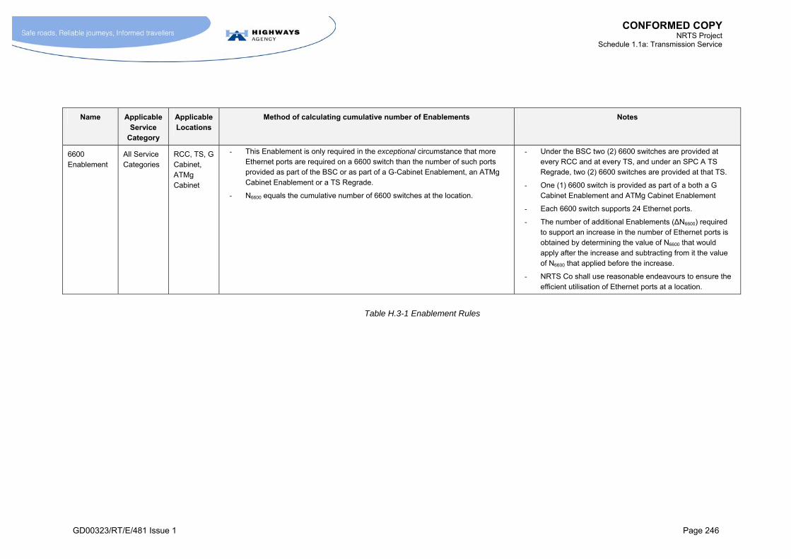
CONFORMED COPY NRTS Project
Schedule 1.1a: Transmission Service
GD00323/RT/E/481 Issue 1 Page 246
Name Applicable Service
Category
Applicable Locations
Method of calculating cumulative number of Enablements Notes
6600 Enablement
All Service Categories
RCC, TS, G Cabinet, ATMg Cabinet
- This Enablement is only required in the exceptional circumstance that more Ethernet ports are required on a 6600 switch than the number of such ports provided as part of the BSC or as part of a G-Cabinet Enablement, an ATMg Cabinet Enablement or a TS Regrade.
- N6600 equals the cumulative number of 6600 switches at the location.
- Under the BSC two (2) 6600 switches are provided at every RCC and at every TS, and under an SPC A TS Regrade, two (2) 6600 switches are provided at that TS.
- One (1) 6600 switch is provided as part of a both a G Cabinet Enablement and ATMg Cabinet Enablement
- Each 6600 switch supports 24 Ethernet ports.
- The number of additional Enablements (ΔN6600) required to support an increase in the number of Ethernet ports is obtained by determining the value of N6600 that would apply after the increase and subtracting from it the value of N6600 that applied before the increase.
- NRTS Co shall use reasonable endeavours to ensure the efficient utilisation of Ethernet ports at a location.
Table H.3-1 Enablement Rules
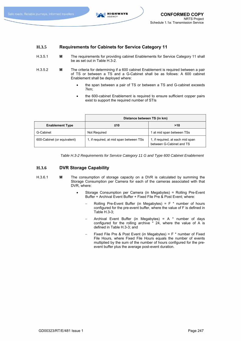
CONFORMED COPY NRTS Project
Schedule 1.1a: Transmission Service
GD00323/RT/E/481 Issue 1 Page 247
H.3.5 Requirements for Cabinets for Service Category 11
H.3.5.1 M The requirements for providing cabinet Enablements for Service Category 11 shall be as set out in Table H.3-2.
H.3.5.2 M The criteria for determining if a 600 cabinet Enablement is required between a pair of TS or between a TS and a G-Cabinet shall be as follows: A 600 cabinet Enablement shall be deployed where:
the span between a pair of TS or between a TS and G-cabinet exceeds 7km;
the 600-cabinet Enablement is required to ensure sufficient copper pairs exist to support the required number of STIs
Distance between TS (in km)
Enablement Type ≤10 >10
G-Cabinet Not Required 1 at mid span between TSs
600-Cabinet (or equivalent) 1, if required, at mid span between TSs 1, if required, at each mid span between G-Cabinet and TS
Table H.3-2 Requirements for Service Category 11 G and Type 600 Cabinet Enablement
H.3.6 DVR Storage Capability
H.3.6.1 M The consumption of storage capacity on a DVR is calculated by summing the Storage Consumption per Camera for each of the cameras associated with that DVR, where:
Storage Consumption per Camera (in Megabytes) = Rolling Pre-Event Buffer + Archival Event Buffer + Fixed File Pre & Post Event; where:
Rolling Pre-Event Buffer (in Megabytes) = F * number of hours configured for the pre-event buffer, where the value of F is defined in Table H.3-3;
Archival Event Buffer (in Megabytes) = A * number of days configured for the rolling archive * 24, where the value of A is defined in Table H.3-3; and
Fixed File Pre & Post Event (in Megabytes) = F * number of Fixed File Hours, where Fixed File Hours equals the number of events multiplied by the sum of the number of hours configured for the pre-event buffer plus the average post-event duration.
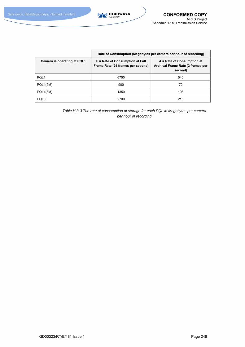
CONFORMED COPY NRTS Project
Schedule 1.1a: Transmission Service
GD00323/RT/E/481 Issue 1 Page 248
Rate of Consumption (Megabytes per camera per hour of recording)
Camera is operating at PQL: F = Rate of Consumption at Full Frame Rate (25 frames per second)
A = Rate of Consumption at Archival Frame Rate (2 frames per
second)
PQL1 6750 540
PQL4(2M) 900 72
PQL4(3M) 1350 108
PQL5 2700 216
Table H.3-3 The rate of consumption of storage for each PQL in Megabytes per camera
per hour of recording

CONFORMED COPY NRTS Project
Schedule 1.1a: Transmission Service
GD00323/RT/E/481 Issue 1 Page 249
I ANNEX I
CAPACITY MODEL
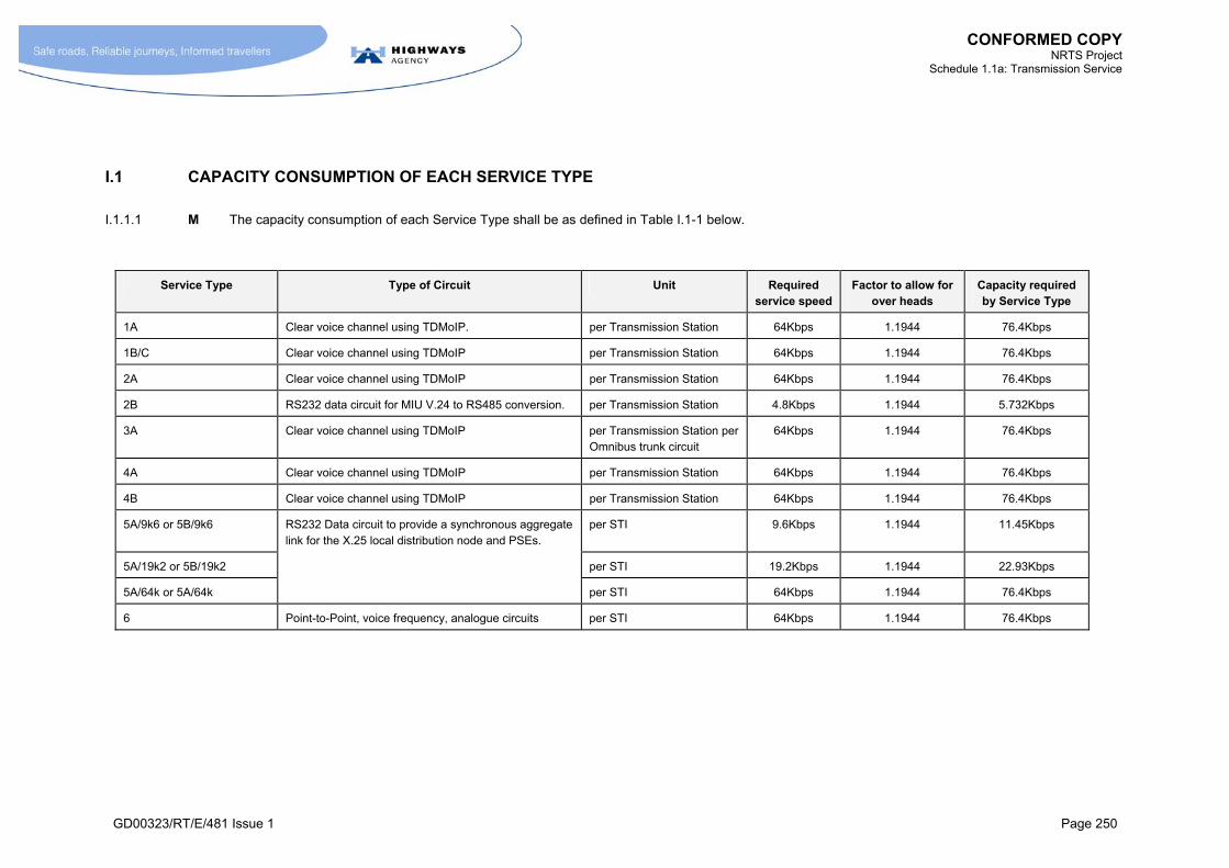
CONFORMED COPY NRTS Project
Schedule 1.1a: Transmission Service
GD00323/RT/E/481 Issue 1 Page 250
I.1 CAPACITY CONSUMPTION OF EACH SERVICE TYPE
I.1.1.1 M The capacity consumption of each Service Type shall be as defined in Table I.1-1 below.
Service Type Type of Circuit Unit Required service speed
Factor to allow for over heads
Capacity required by Service Type
1A Clear voice channel using TDMoIP. per Transmission Station 64Kbps 1.1944 76.4Kbps
1B/C Clear voice channel using TDMoIP per Transmission Station 64Kbps 1.1944 76.4Kbps
2A Clear voice channel using TDMoIP per Transmission Station 64Kbps 1.1944 76.4Kbps
2B RS232 data circuit for MIU V.24 to RS485 conversion. per Transmission Station 4.8Kbps 1.1944 5.732Kbps
3A Clear voice channel using TDMoIP per Transmission Station per Omnibus trunk circuit
64Kbps 1.1944 76.4Kbps
4A Clear voice channel using TDMoIP per Transmission Station 64Kbps 1.1944 76.4Kbps
4B Clear voice channel using TDMoIP per Transmission Station 64Kbps 1.1944 76.4Kbps
5A/9k6 or 5B/9k6 RS232 Data circuit to provide a synchronous aggregate link for the X.25 local distribution node and PSEs.
per STI 9.6Kbps 1.1944 11.45Kbps
5A/19k2 or 5B/19k2 per STI 19.2Kbps 1.1944 22.93Kbps
5A/64k or 5A/64k per STI 64Kbps 1.1944 76.4Kbps
6 Point-to-Point, voice frequency, analogue circuits per STI 64Kbps 1.1944 76.4Kbps

CONFORMED COPY NRTS Project
Schedule 1.1a: Transmission Service
GD00323/RT/E/481 Issue 1 Page 251
Service Type Type of Circuit Unit Required service speed
Factor to allow for over heads
Capacity required by Service Type
8Rx, 8RDx, 8Cx Generic IP services. As these services enter as IP, no overheads are incurred
per STI 1.2kbps
2.4kbps
9.6kbps
14.4kbps
28.8kbps
33.6kbps
64kbps
128kbps
256kbps
512kbps
1.0248Mbps
2.048Mbps
8.448Mbps
100Mbps
N/A 1.2kbps
2.4kbps
9.6kbps
14.4kbps
28.8kbps
33.6kbps
64kbps
128kbps
256kbps
512kbps
1.0248Mbps
2.048Mbps
8.448Mbps
100Mbps
9CRx Point-to-Point circuits per STI XMbps 1.1944 (x) multiplied by 1.1944
10 Video stream to support PQL1, PQL2, PQL3 within Switched Video Network
per video channel 15Mbps 15Mbps
Video stream to support PQL 4(2M) within Switched Video Network
per video channel 2Mbps 2Mbps
Video stream to support PQL 4(3M) within Switched Video Network
per video channel 3Mbps 3Mpbs

CONFORMED COPY NRTS Project
Schedule 1.1a: Transmission Service
GD00323/RT/E/481 Issue 1 Page 252
Service Type Type of Circuit Unit Required service speed
Factor to allow for over heads
Capacity required by Service Type
10
(Continued)
Video stream to support PQL5 within Switched Video Network
6Mbps 6Mbps
11 Packetised voice using VoIP UDP frame for transmission over the core IP network.
per STI 64Kbps 84.7Kbps
Table I.1-1 Capacity Consumption of each Service Type

CONFORMED COPY NRTS Project
Schedule 1.1a: Transmission Service
GD00323/RT/E/481 Issue 1 Page 253
I.2 NETWORK CAPACITY TABLE
I.2.1.1 M The capacity provided by each link in the Base Network shall be as shown below. By mutual agreement capacity may be spatially redistributed by changing the locations of equipment subject to the constraint that the overall quantity of transmission equipment is not reduced.
I.2.2 National Links
Link # Transmission Station A
Transmission Station B
Bandwidth Link type
Usable Bandwidth
N0001 Colnbrook Darenth 2.5G POS 2.25G
N0002 Darenth London North 2.5G POS 2.25G
N0003 London North Colnbrook 2.5G POS 2.25G
N0004 Colnbrook Almondsbury 2.5G POS 2.25G
N0005 Colnbrook Portsbridge 2.5G POS 2.25G
N0006 Colnbrook Coleshill 2.5G POS 2.25G
N0007 Almondsbury Sowton 2.5G POS 2.25G
N0008 Almondsbury Warndon 2.5G POS 2.25G
N0009 Coleshill Warndon 2.5G POS 2.25G
N0010 Coleshill Stafford 2.5G POS 2.25G
N0011 Stafford Warndon 2.5G POS 2.25G
N0012 London North Catthorpe 2.5G POS 2.25G
N0013 Coleshill Catthorpe 2.5G POS 2.25G
N0014 Catthorpe Aston 2.5G POS 2.25G
N0015 Aston Lofthouse 2.5G POS 2.25G
N0016 Stafford Lymm 2.5G POS 2.25G
N0017 Stafford Lofthouse 2.5G POS 2.25G
N0018 Lymm Worsley 2.5G POS 2.25G
N0019 Worsley Lofthouse 2.5G POS 2.25G
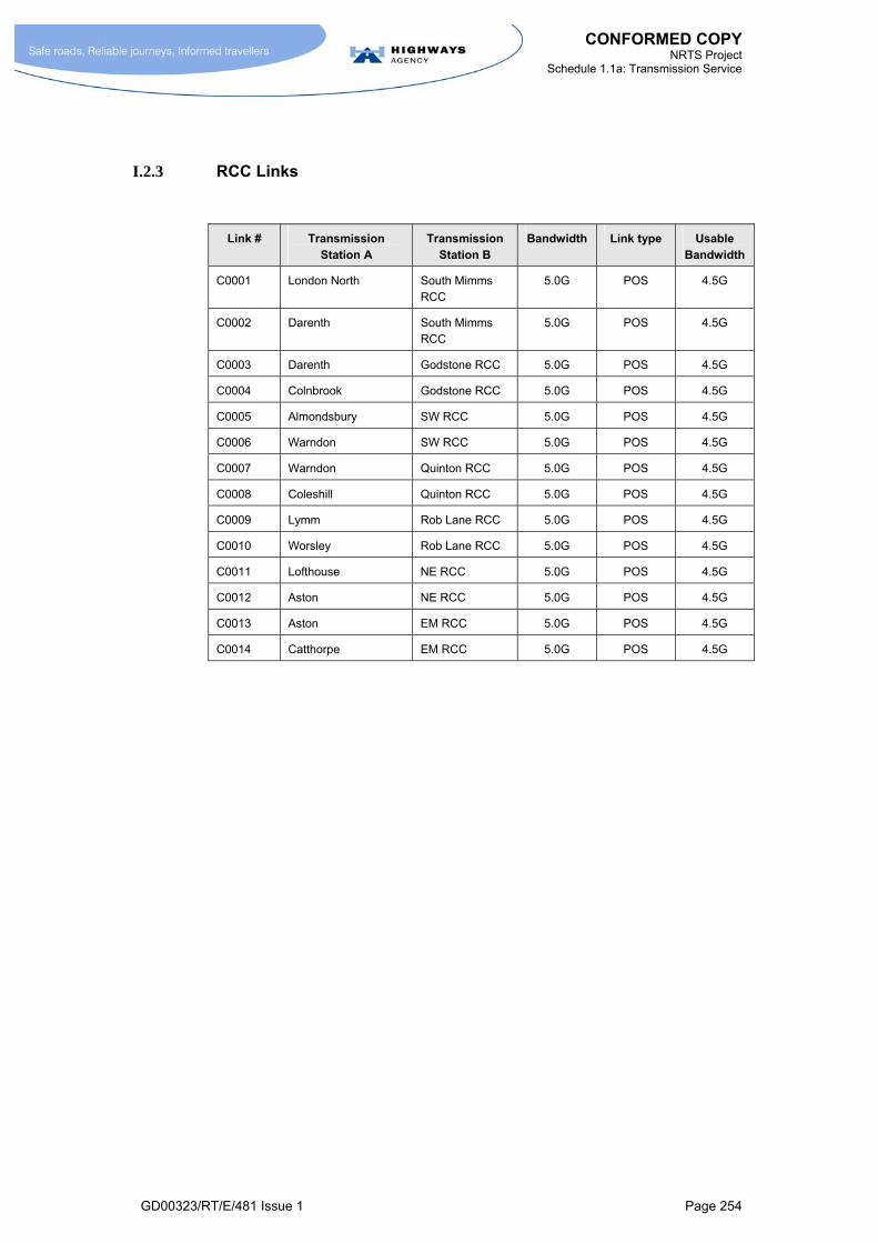
CONFORMED COPY NRTS Project
Schedule 1.1a: Transmission Service
GD00323/RT/E/481 Issue 1 Page 254
I.2.3 RCC Links
Link # Transmission Station A
Transmission Station B
Bandwidth Link type Usable Bandwidth
C0001 London North South Mimms RCC
5.0G POS 4.5G
C0002 Darenth South Mimms RCC
5.0G POS 4.5G
C0003 Darenth Godstone RCC 5.0G POS 4.5G
C0004 Colnbrook Godstone RCC 5.0G POS 4.5G
C0005 Almondsbury SW RCC 5.0G POS 4.5G
C0006 Warndon SW RCC 5.0G POS 4.5G
C0007 Warndon Quinton RCC 5.0G POS 4.5G
C0008 Coleshill Quinton RCC 5.0G POS 4.5G
C0009 Lymm Rob Lane RCC 5.0G POS 4.5G
C0010 Worsley Rob Lane RCC 5.0G POS 4.5G
C0011 Lofthouse NE RCC 5.0G POS 4.5G
C0012 Aston NE RCC 5.0G POS 4.5G
C0013 Aston EM RCC 5.0G POS 4.5G
C0014 Catthorpe EM RCC 5.0G POS 4.5G
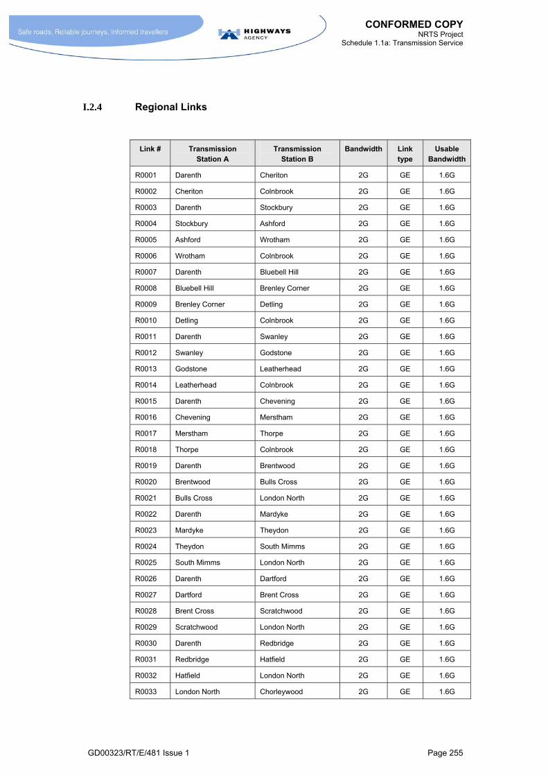
CONFORMED COPY NRTS Project
Schedule 1.1a: Transmission Service
GD00323/RT/E/481 Issue 1 Page 255
I.2.4 Regional Links
Link # Transmission Station A
Transmission Station B
Bandwidth Link type
Usable Bandwidth
R0001 Darenth Cheriton 2G GE 1.6G
R0002 Cheriton Colnbrook 2G GE 1.6G
R0003 Darenth Stockbury 2G GE 1.6G
R0004 Stockbury Ashford 2G GE 1.6G
R0005 Ashford Wrotham 2G GE 1.6G
R0006 Wrotham Colnbrook 2G GE 1.6G
R0007 Darenth Bluebell Hill 2G GE 1.6G
R0008 Bluebell Hill Brenley Corner 2G GE 1.6G
R0009 Brenley Corner Detling 2G GE 1.6G
R0010 Detling Colnbrook 2G GE 1.6G
R0011 Darenth Swanley 2G GE 1.6G
R0012 Swanley Godstone 2G GE 1.6G
R0013 Godstone Leatherhead 2G GE 1.6G
R0014 Leatherhead Colnbrook 2G GE 1.6G
R0015 Darenth Chevening 2G GE 1.6G
R0016 Chevening Merstham 2G GE 1.6G
R0017 Merstham Thorpe 2G GE 1.6G
R0018 Thorpe Colnbrook 2G GE 1.6G
R0019 Darenth Brentwood 2G GE 1.6G
R0020 Brentwood Bulls Cross 2G GE 1.6G
R0021 Bulls Cross London North 2G GE 1.6G
R0022 Darenth Mardyke 2G GE 1.6G
R0023 Mardyke Theydon 2G GE 1.6G
R0024 Theydon South Mimms 2G GE 1.6G
R0025 South Mimms London North 2G GE 1.6G
R0026 Darenth Dartford 2G GE 1.6G
R0027 Dartford Brent Cross 2G GE 1.6G
R0028 Brent Cross Scratchwood 2G GE 1.6G
R0029 Scratchwood London North 2G GE 1.6G
R0030 Darenth Redbridge 2G GE 1.6G
R0031 Redbridge Hatfield 2G GE 1.6G
R0032 Hatfield London North 2G GE 1.6G
R0033 London North Chorleywood 2G GE 1.6G

CONFORMED COPY NRTS Project
Schedule 1.1a: Transmission Service
GD00323/RT/E/481 Issue 1 Page 256
Link # Transmission Station A
Transmission Station B
Bandwidth Link type
Usable Bandwidth
R0034 Chorleywood Denham 2G GE 1.6G
R0035 Denham Colnbrook 2G GE 1.6G
R0036 Colnbrook Bray 2G GE 1.6G
R0037 Bray Grittenham 2G GE 1.6G
R0038 Grittenham Almondsbury 2G GE 1.6G
R0039 Colnbrook Chieveley 2G GE 1.6G
R0040 Chieveley Stanton St. Quinton 2G GE 1.6G
R0041 Stanton St. Quinton Almondsbury 2G GE 1.6G
R0042 Colnbrook Cutbush Lane 2G GE 1.6G
R0043 Cutbush Lane Poughley 2G GE 1.6G
R0044 Poughley Tormanton 2G GE 1.6G
R0045 Tormanton Almondsbury 2G GE 1.6G
R0046 Colnbrook Burnt Hill 2G GE 1.6G
R0047 Burnt Hill Badbury 2G GE 1.6G
R0048 Badbury Hambrook 2G GE 1.6G
R0049 Hambrook Almondsbury 2G GE 1.6G
R0050 Colnbrook Frimley 2G GE 1.6G
R0051 Frimley Popham 2G GE 1.6G
R0052 Popham Chilworth 2G GE 1.6G
R0053 Chilworth Portsbridge 2G GE 1.6G
R0054 Colnbrook Hook 2G GE 1.6G
R0055 Hook Barr End 2G GE 1.6G
R0056 Barr End Parkgate 2G GE 1.6G
R0057 Parkgate Portsbridge 2G GE 1.6G
R0058 Colnbrook Handy Cross 2G GE 1.6G
R0059 Handy Cross Wendlebury 2G GE 1.6G
R0060 Wendlebury Burton Dassett 2G GE 1.6G
R0061 Burton Dassett Coleshill 2G GE 1.6G
R0062 Colnbrook Manor Farm 2G GE 1.6G
R0063 Manor Farm Kings Sutton 2G GE 1.6G
R0064 Kings Sutton Longbridge 2G GE 1.6G
R0065 Longbridge Coleshill 2G GE 1.6G
R0066 Colnbrook Heston 2G GE 1.6G
R0067 Almondsbury Awkley 2G GE 1.6G
R0068 Awkley Lawence Weston 2G GE 1.6G
R0069 Lawence Weston Huntsworth 2G GE 1.6G

CONFORMED COPY NRTS Project
Schedule 1.1a: Transmission Service
GD00323/RT/E/481 Issue 1 Page 257
Link # Transmission Station A
Transmission Station B
Bandwidth Link type
Usable Bandwidth
R0070 Huntsworth Sowton 2G GE 1.6G
R0071 Almondsbury Pilning 2G GE 1.6G
R0072 Pilning Edithmead 2G GE 1.6G
R0073 Edithmead Cullompton 2G GE 1.6G
R0074 Cullompton Sowton 2G GE 1.6G
R0075 Almondsbury Aust Rock 2G GE 1.6G
R0076 Aust Rock St Georges 2G GE 1.6G
R0077 St Georges Chelston 2G GE 1.6G
R0078 Chelston Sowton 2G GE 1.6G
R0079 Almondsbury Haresfield 2G GE 1.6G
R0080 Haresfield Strensham 2G GE 1.6G
R0081 Strensham Warndon 2G GE 1.6G
R0082 Almondsbury Michaelwood 2G GE 1.6G
R0083 Michaelwood Uckington 2G GE 1.6G
R0084 Uckington Warndon 2G GE 1.6G
R0085 Warndon Quinton NOC 2G GE 1.6G
R0086 Quinton NOC Coleshill 2G GE 1.6G
R0087 Warndon Umberslade 2G GE 1.6G
R0088 Umberslade Coleshill 2G GE 1.6G
R0089 Coleshill Perry Barr 2G GE 1.6G
R0090 Perry Barr Ray Hall 2G GE 1.6G
R0091 Ray Hall Shifnal 2G GE 1.6G
R0092 Shifnal Stafford 2G GE 1.6G
R0093 Warndon Bromsgrove 2G GE 1.6G
R0094 Bromsgrove Laney Green 2G GE 1.6G
R0095 Laney Green Stafford 2G GE 1.6G
R0096 Warndon Titford Lane 2G GE 1.6G
R0097 Titford Lane Hilton Park 2G GE 1.6G
R0098 Hilton Park Stafford 2G GE 1.6G
R0099 London North Breakspears 2G GE 1.6G
R0100 Breakspears Bedford 2G GE 1.6G
R0101 Bedford Rotherthorpe 2G GE 1.6G
R0102 Rotherthorpe Catthorpe 2G GE 1.6G
R0103 London North Luton 2G GE 1.6G
R0104 Luton Newport Pagnall 2G GE 1.6G
R0105 Newport Pagnall Watford Gap 2G GE 1.6G

CONFORMED COPY NRTS Project
Schedule 1.1a: Transmission Service
GD00323/RT/E/481 Issue 1 Page 258
Link # Transmission Station A
Transmission Station B
Bandwidth Link type
Usable Bandwidth
R0106 Watford Gap Catthorpe 2G GE 1.6G
R0107 Coleshill Ansty 2G GE 1.6G
R0108 Ansty Catthorpe 2G GE 1.6G
R0109 Curdsworth Dorndon 2G GE 1.6G
R0110 Coleshill Curdsworth 2G GE 1.6G
R0111 Dordon Catthorpe 2G GE 1.6G
R0112 Catthorpe Leicester Forest 2G GE 1.6G
R0113 Leicester Forest Sandiacre 2G GE 1.6G
R0114 Sandiacre Aston 2G GE 1.6G
R0115 Catthorpe Shepshed 2G GE 1.6G
R0116 Shepshed Felley 2G GE 1.6G
R0117 Felley Aston 2G GE 1.6G
R0118 Catthorpe Kegworth 2G GE 1.6G
R0119 Kegworth Heath 2G GE 1.6G
R0120 Heath Aston 2G GE 1.6G
R0121 Aston Thorpe Helsey 2G GE 1.6G
R0122 Thorpe Helsey Lofthouse 2G GE 1.6G
R0123 Aston Haigh 2G GE 1.6G
R0124 Haigh Lofthouse 2G GE 1.6G
R0125 Aston Wadworth 2G GE 1.6G
R0126 Wadworth North Ings 2G GE 1.6G
R0127 Aston North Ings 2G GE 1.6G
R0128 Stafford Stone 2G GE 1.6G
R0129 Stone Sandbach 2G GE 1.6G
R0130 Sandbach Lymm 2G GE 1.6G
R0131 Stafford Keele 2G GE 1.6G
R0132 Keele Knutsford 2G GE 1.6G
R0133 Knutsford Lymm 2G GE 1.6G
R0134 Lymm Cheadle 2G GE 1.6G
R0135 Cheadle Denton 2G GE 1.6G
R0136 Denton Worsley 2G GE 1.6G
R0137 Lymm Brinnington 2G GE 1.6G
R0138 Brinnington Worsley 2G GE 1.6G
R0139 Lymm Stretford 2G GE 1.6G
R0140 Stretford Worsley 2G GE 1.6G
R0141 Lymm Eccles 2G GE 1.6G

CONFORMED COPY NRTS Project
Schedule 1.1a: Transmission Service
GD00323/RT/E/481 Issue 1 Page 259
Link # Transmission Station A
Transmission Station B
Bandwidth Link type
Usable Bandwidth
R0142 Eccles Worsley 2G GE 1.6G
R0143 Lymm Croft 2G GE 1.6G
R0144 Croft Worsley 2G GE 1.6G
R0145 Lymm Orrell 2G GE 1.6G
R0146 Orrell Worsley 2G GE 1.6G
R0147 Lymm Charnock Green 2G GE 1.6G
R0148 Charnock Green Worsley 2G GE 1.6G
R0149 Lymm Broughton 2G GE 1.6G
R0150 Broughton Westhoughton 2G GE 1.6G
R0151 Westhoughton Worsley 2G GE 1.6G
R0152 Lymm Bamber Bridge 2G GE 1.6G
R0153 Bamber Bridge Whitebirk 2G GE 1.6G
R0154 Whitebirk Worsley 2G GE 1.6G
R0155 Worsley Simster 2G GE 1.6G
R0156 Simster Outlane 2G GE 1.6G
R0157 Outlane Lofthouse 2G GE 1.6G
R0158 Worsley Milnrow 2G GE 1.6G
R0159 Milnrow Chain Bar 2G GE 1.6G
R0160 Chain Bar Lofthouse 2G GE 1.6G
R0161 Lofthouse Grangemoor 2G GE 1.6G
R0162 Grangemoor Allerton Moor 2G GE 1.6G
R0163 Allerton Moor Dishforth 2G GE 1.6G
R0164 Grangemoor Holmfield 2G GE 1.6G
R0165 Holmfield Dishforth 2G GE 1.6G

CONFORMED COPY NRTS Project
Schedule 1.1a: Transmission Service
GD00323/RT/E/481 Issue 1 Page 260
I.2.5 SPC B Links
Link # Transmission Station A
Transmission Station B
Bandwidth Link type Usable Bandwidth
B0001 Merstham Balcombe 2M E1 1.920M
B0002 Theydon Little Hallingbury 2M E1 1.920M
B0003 Little Hallingbury Wicken Bonhunt 2M E1 1.920M
B0004 Wicken Bonhunt Duxford 2M E1 1.920M
B0005 North Ings Scunthorpe 2M E1 1.920M
B0006 Scunthorpe Barnetby 2M E1 1.920M
B0007 North Ings Langham 2M E1 1.920M
B0008 Langham Ferrybridge (Holmsfield)
2M E1 1.920M
B0009 Cleasby Bradbury 2M E1 1.920M
B0010 Bradbury Carville 2M E1 1.920M
B0011 Broughton Forton 4M E1 3.840M
B0012 Forton Lancaster 4M E1 3.840M
B0013 Lancaster Kendal 4M E1 3.840M
B0014 Kendal Sedburgh 2M E1 1.920M
B0015 Sedburgh Tebay 2M E1 1.920M
B0016 Tebay Shap 2M E1 1.920M
B0017 Shap Penrith 2M E1 1.920M
B0018 Penrith Southwaite 2M E1 1.920M
B0019 Lymm Tarbock 2M E1 1.920M
B0020 Tarbock Orrell 2M E1 1.920M
B0021 Lymm Preston Brook 2M E1 1.920M
B0022 Preston Brook Stoak 2M E1 1.920M
B0023 Stoak Hooton 2M E1 1.920M
B0024 Hooton Moreton 2M E1 1.920M
B0025 Hatfield Stevenage 2M E1 1.920M
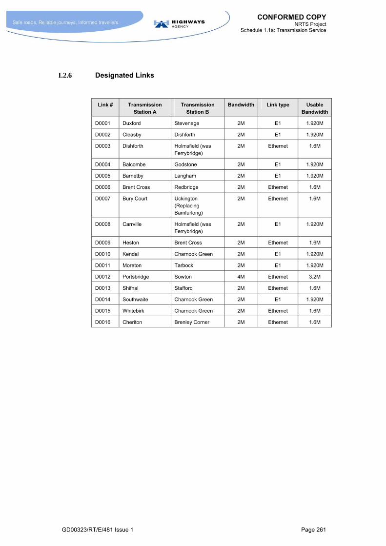
CONFORMED COPY NRTS Project
Schedule 1.1a: Transmission Service
GD00323/RT/E/481 Issue 1 Page 261
I.2.6 Designated Links
Link # Transmission Station A
Transmission Station B
Bandwidth Link type Usable Bandwidth
D0001 Duxford Stevenage 2M E1 1.920M
D0002 Cleasby Dishforth 2M E1 1.920M
D0003 Dishforth Holmsfield (was Ferrybridge)
2M Ethernet 1.6M
D0004 Balcombe Godstone 2M E1 1.920M
D0005 Barnetby Langham 2M E1 1.920M
D0006 Brent Cross Redbridge 2M Ethernet 1.6M
D0007 Bury Court Uckington (Replacing Bamfurlong)
2M Ethernet 1.6M
D0008 Carrville Holmsfield (was Ferrybridge)
2M E1 1.920M
D0009 Heston Brent Cross 2M Ethernet 1.6M
D0010 Kendal Charnook Green 2M E1 1.920M
D0011 Moreton Tarbock 2M E1 1.920M
D0012 Portsbridge Sowton 4M Ethernet 3.2M
D0013 Shifnal Stafford 2M Ethernet 1.6M
D0014 Southwaite Charnook Green 2M E1 1.920M
D0015 Whitebirk Charnook Green 2M Ethernet 1.6M
D0016 Cheriton Brenley Corner 2M Ethernet 1.6M

CONFORMED COPY NRTS Project
Schedule 1.1a: Transmission Service
GD00323/RT/E/481 Issue 1 Page 262
J ANNEX J
NON PTO DESIGNATED LINKS

CONFORMED COPY NRTS Project
Schedule 1.1a: Transmission Service
GD00323/RT/E/481 Issue 1 Page 263
J.1 NON-PTO DESIGNATED LINKS
J.1.1.1 M NRTS Co shall be responsible for the following Non PTO Designated Links under the Base Service Charge. NRTS Co shall be responsible for all costs (including maintenance) for these Designated Links with the exception given in paragraphs J.1.1.2 and J.1.1.3.
J.1.1.2 M NRTS Co shall charge the HA the costs of wayleaves for cables, leases for use of land and buildings, and Ofcom licences for radio links, at cost plus the Designated Link Mark up.
J.1.1.3 M In relation to paragraph J.1.1.1, NRTS Co may request that the HA give consent to the replacement of a life-expired microwave Designated Link through an Ad Hoc Project. The HA shall not unreasonably withhold its consent provided that:
reasonable endeavours have been made by NRTS Co to extend the life of the existing system, and
a failure to undertake replacement would result in a significant risk to service delivery.
J.1.1.4 M In relation to replacements described in paragraph J.1.1.3, NRTS Co shall follow the Designated Link procedure described in section H.2.2. In evaluating options, NRTS Co shall include the evaluation of low cost solutions such as the refurbishment of existing systems and replacement of unreliable components of existing systems. An agreed set of replacement criteria shall be developed by NRTS Co as part of the Predicative Asset Management System (see Schedule 1.2 paragraphs 5.9.2.2 to 5.9.2.8).
Site A Site B Type Of Link Cable/Radio Route
Manchester CO
Denton TS 24 Fibre cable HA cable on Railtrack Land
Manchester CO
Stretford TS 24 Fibre cable HA cable on Railtrack Land
Hutton Hall CO
Bamber Bridge TS
16x2Mbps Pt to Pt Radio
No repeater
Wakefield CO Lofthouse TS Composite fibre + 30pr copper cables
M1, A650
Perry Bar CO Perry Bar TS Composite fibre + 30pr copper cable
direct cable
Stafford CO Stafford TS Composite fibre A49, A449 and canal
Hindlip Hall Warndon TS Composite fibre + 30pr copper
A4538, M5
Leek Wooton CO
Longbridge TS Composite fibre + 30pr copper
A46 and private land
Northampton CO.
Rothersthorpe TS
24 fibre + 40 pr copper
A508 from J15 of M1
Leicester CO Leicester Forest TS
Composite fibre + 30pr copper
B1440, A543
Ripley CO Felley TS 24 fibre A38

CONFORMED COPY NRTS Project
Schedule 1.1a: Transmission Service
GD00323/RT/E/481 Issue 1 Page 264
Site A Site B Type Of Link Cable/Radio Route
Welwyn CO A1(M) Cabinet Composite fibre + 30pr copper
A1(M), A1000
Chigwell CO M11 Composite fibre + 30pr copper
direct cable
Kempston CO Bedford TS 16x2Mbps Pt to Pt Radio
Via Brogborough Hill Repeater
Hinchinbrook CO
Alconbury TS Composite fibre + 30pr copper
A14, A1
Maidstone CO Detling TS Composite fibre + 30pr copper
A249 and LA road
Maidstone CO Detling TS 4x2Mbps Pt to Pt Radio
No repeater
Kidlington CO Wendlebury TS Composite fibre + 30pr copper
A34 and LA road
[Not Used] [Not Used] [Not Used] [Not Used]
Scratchwood CO
M1 Cabinet Composite fibre + 30pr copper
direct cable
Heston CO M4 Cabinet Composite fibre + 30pr copper
direct cable
Portishead CO Lawrence Weston TS (via M5 Cabinet)
Portishead CO to M5 Cabinet:
24 fibre + 10pr copper
M5 Cabinet to Lawrence Weston:
Two 12 fibre composite cables
B3124 and local road
Portishead CO Lawrence Weston
4x2Mbps Pt to Pt Radio
No repeater
Waterwells CO
Haresfield TS 24 fibre + 40 pr copper
A38
Exeter CO Cullompton TS 24 fibre + 40 pr copper
A3053 to M5 Jct 29
Netley CO Parkgate TS 16x2Mbps Radio Repeater at Freeth allotments
NTCC building M5 J3 2 x 12 fibre direct cable
Detling TS Bluebell Hill TS 30pr Copper + 12 + 12 Composite Fibre
A229 From J6 M20 to J3 M2
Detling TS Stockbury TS 30pr Copper + 12 + 12 Composite Fibre
A249 From J7 M20 to J5 M2
Pilning TS Aust Rock TS Dark fibre pair from Welsh Office
M4 and M48 across Severn Crossings via M4 J23

CONFORMED COPY NRTS Project
Schedule 1.1a: Transmission Service
GD00323/RT/E/481 Issue 1 Page 265
Site A Site B Type Of Link Cable/Radio Route
RCCs (7 off) Relevant motorways
All RCC's are directly cabled to the motorway network by dual routed fibre optic cables
A 40 pair copper cable might also be included in the link between the TCC and the motorway network.

CONFORMED COPY NRTS Project
Schedule 1.1a: Transmission Service
GD00323/RT/E/481 Issue 1 Page 266
K ANNEX K
METHODOLOGY FOR CONVERTING ST1B TO ST1A AS PART OF A
PROGRAMME OF NMCS1 TO NMCS2 CONVERSION

CONFORMED COPY NRTS Project
Schedule 1.1a: Transmission Service
GD00323/RT/E/481 Issue 1 Page 267
K.1 NMCS1 TO NMCS2 CONVERSION
K.1.1 Background
K.1.1.1 M The HA are planning to convert all remaining NMCS1 signal sites to NMCS2 within the next 3 years. Prior to the Take-On of Services by NRTS Co, a programme of work to undertake this conversion (hereafter referred to as the “Conversion Programme”) is to commence in the first quarter of 2005 and such work shall be undertaken by existing contractors of the HA.
K.1.1.2 M The Conversion Programme is to be co-ordinated and managed through a project board and technical assurance team, both of which have been set up by the HA.
K.1.1.3 M The Conversion Programme involves exchanging the following roadside equipment listed below in the manner specified:
Replacing existing central reserve signal posts, signals and signal drivers with new central reserve signal posts and signals but with an NMCS2 (RS485) interface.
Replacing NMCS1 Responders that currently control the NMCS1 signals with NMCS2 Transponders to control the new signals.
K.1.2 Constraints and assumptions
K.1.2.1 M The Conversion Programme seeks to achieve the NMCS1 to NMCS2 conversion using existing roadside cabinets and cables. To accomplish this there is a need to “convert” existing NMCS1 transmission circuits (ST1B and 1C) to NMCS2 transmission circuits (ST1A) using the existing longitudinal and local cable infrastructure.
K.1.2.2 M Current implementations of NMCS1 (ST1B and 1C) and NMCS2 (ST1A) Transmission Services, as defined by the DMRB and the GeneSYS service solution, require no active transmission equipment between a TS and the roadside.
K.1.2.3 M Work undertaken by the HA indicates the need to maintain both NMCS1 and NMCS2 Transmission Services (ST1B, ST1C & ST1A) concurrently for part of the duration of the conversion. This requirement impacts on the two elements of the transmission network as follows:
The trunk network (between TS and CO) – Duplicate circuits can be provided on this part of the network by retaining NMCS1 circuits over the existing SDH and PDH networks and commissioning new NMCS2 circuits across either the SDH and PDH networks or over the GeneSYS core network once it is operational. This complies with GeneSYS’ approach of maintaining the use of the SDH network after the Execution Date.
The roadside network (between roadside device and TS) – The need for duplicated circuits on this part of the network is likely to be for a short period of time and is dependent on the availability of cable pairs and spare capacity on Mini-carrier systems and any PCM systems based on DSL solutions that may have replaced any Mini-carrier systems.
K.1.2.4 M In areas where 30-pair longitudinal cabling exists it is safe to assume that sufficient spare pairs exist to support duplicate circuits at the roadside and also to provide circuits back to the nearest point on the trunk network for onward transmission to the CO, without the need to reconfigure existing services.

CONFORMED COPY NRTS Project
Schedule 1.1a: Transmission Service
GD00323/RT/E/481 Issue 1 Page 268
K.1.2.5 M In areas where 20-pair longitudinal cabling exists two constraining factors influence the possible solution. These are summarised below:
a) The number of spare cable pairs in the cable.
b) The number of spare channels in any mini carrier systems.
K.1.3 Potential Solutions
K.1.3.1 M Two solutions have been developed by the HA. These solutions are listed below:
Solution 1
K.1.3.2 M Solution 1 is the simplest solution to implement and involves the least reconfiguration of existing arrangements. This solution is expected to be used in areas with 30-pair longitudinal cables where:
there is sufficient capacity in the TS to CO network (using either SDH, PDH, Mini-carrier, PCM over DSL or combinations of these technologies), and
there are 3 spare pairs (2x 22mH loaded and 1x unloaded pair) in the copper cable network.
K.1.3.3 M Solution 1 requires NRTS Co to establish new circuits between the CO and TSs across the transmission network and the configure test and link longitudinal and RS485 circuits using available cable pairs. This work shall be performed in advance by NRTS Co and in isolation from the other conversion activities undertaken by other HA contractors (typically RMC and technology framework contractors).
Solution 2
K.1.3.4 M In areas with 20-pair longitudinal cables, there may be insufficient spare pairs to allow the implementation of Solution 1 as set out above. Solution 2 does not require any additional loaded pairs to be found in the cable.
K.1.3.5 M Solution 2 assumes that there is sufficient capacity in the TS to CO network (using either SDH, PDH, Mini-carrier, PCM over DSL or combinations of these technologies) but insufficient spare pairs in the copper cable network to provide duplicated circuits.
K.1.3.6 M Solution 2 is described below in four steps. The description should be read in conjunction with the diagrams in this Annex K.

CONFORMED COPY NRTS Project
Schedule 1.1a: Transmission Service
GD00323/RT/E/481 Issue 1 Page 269
Step 1
K.1.3.6.1. M Groups of three NMCS1 responders over a span of 6km are selected and RS485 circuits are configured using unallocated unloaded pairs (typically pairs 7 and 8 on 20-pair cable or pair 13 or 14 on 30-pair cable). The circuits feed out from the central responder to the other two responders sited 3km on either side of the central responder.
Step 2
K.1.3.6.2. M The HA will then take three NMCS1 signal sites out of service and replace these with NMCS2 signals and associated signal drivers. The existing three Responders will also be removed and replaced with a single 21-Bit Transponder at the middle signal. The 21-Bit Transponder will be connected to the RS485 circuits and the signal drivers at all three sites will also be connected to the same RS485 circuits. The location of the new NRTS SDP (1A-4) for each signal site shall remain unchanged i.e. in the base of the 600 cabinet associated with each signal site.
K.1.3.6.3. M This Step 2 is then repeated for the other groups of three responders sharing the same 200bps main data circuit back to local TS.
Step 3
K.1.3.6.4. M Two existing pairs (88mH loaded) currently used for the NMCS2 telephone circuits (between TLC and responders) are made available to provide an additional 4 wire circuit suitable for interconnecting 200bps modems. This will be used as a temporary circuit to connect the 21-Bit Transponders back to the CO freeing up the existing main data circuit (typically pairs 1 and 2) to be re-tested for NMCS2 use and connection into the NMCS2 LCC port. This Step 3 will only be undertaken on completion of all Step 2s for a given section of motorway. This will minimise the down time for two existing telephone circuits.
Step 4
K.1.3.6.5. M Following completion of Step 3 above, all the 21-Bit Transponders for a defined stretch of road will be replaced with Standard NMCS2 Transponders which are connected to the new NMCS2 main data circuits. The temporary NMCS1 data circuit is reconnected to the NMCS2 telephone system.
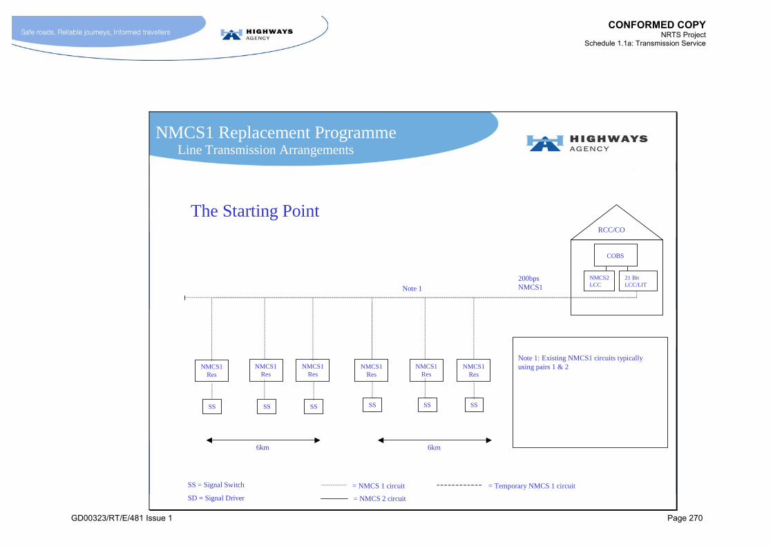
CONFORMED COPY NRTS Project
Schedule 1.1a: Transmission Service
GD00323/RT/E/481 Issue 1 Page 270
NMCS1 Replacement ProgrammeLine Transmission Arrangements
RCC/CO
SS = Signal Switch
SD = Signal Driver
= NMCS 1 circuit
= NMCS 2 circuit
200bps NMCS1
The Starting Point
Note 1: Existing NMCS1 circuits typically using pairs 1 & 2
COBS
21 BitLCC/LIT
NMCS2LCC
= Temporary NMCS 1 circuit
6km6km
NMCS1Res
NMCS1Res
NMCS1Res
SSSSSS
NMCS1Res
NMCS1Res
NMCS1Res
SSSSSS
Note 1
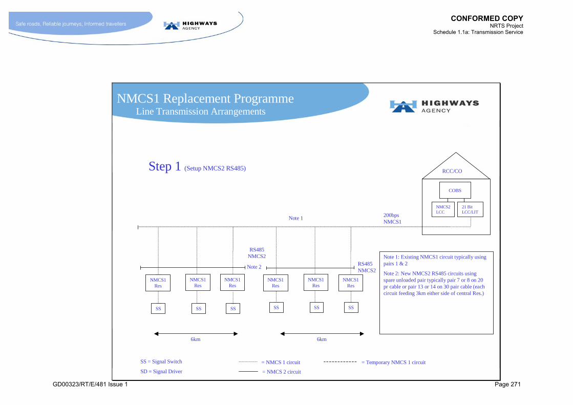
CONFORMED COPY NRTS Project
Schedule 1.1a: Transmission Service
GD00323/RT/E/481 Issue 1 Page 271
NMCS1 Replacement Programme
RCC/CO
200bps NMCS1
RS485 NMCS2
6km6km
Step 1 (Setup NMCS2 RS485)
Note 1: Existing NMCS1 circuit typically using pairs 1 & 2
Note 2: New NMCS2 RS485 circuits using spare unloaded pair typically pair 7 or 8 on 20 pr cable or pair 13 or 14 on 30 pair cable (each circuit feeding 3km either side of central Res.)
COBS
21 BitLCC/LIT
NMCS2LCC
SS = Signal Switch
SD = Signal Driver
= NMCS 1 circuit
= NMCS 2 circuit
= Temporary NMCS 1 circuit
SSSSSS
RS485 NMCS2
SSSSSS
Note 1
Note 2
Line Transmission Arrangements
NMCS1Res
NMCS1Res
NMCS1Res
NMCS1Res
NMCS1Res
NMCS1Res

CONFORMED COPY NRTS Project
Schedule 1.1a: Transmission Service
GD00323/RT/E/481 Issue 1 Page 272
NMCS1 Replacement Programme
RCC/CO
21 bitTrans
SDSDSD
200bps NMCS1
RS485 NMCS2
6km6km
Step 2a (Replace Section 1)
Note 1: Existing NMCS1 circuit typically using pairs 1 & 2
Note 2: New NMCS2 RS485 circuit using spare unloaded pair typically pair 7 or 8 on 20 pr cable or pair 13 or 14 on 30 pair cable (each circuit feeding 3km either side of central Res.)
Note 3: Qty 3 NMCS1 responders removed and replaced with a 21 Bit Transponder connected to 3 Signal drivers via the new RS485 circuit (using existing cables connected through existing Responder cabinets)
NMCS1Res
NMCS1Res
NMCS1Res
COBS
21 BitLCC/LIT
NMCS2LCC
Note 3
SS = Signal Switch
SD = Signal Driver
= NMCS 1 circuit
= NMCS 2 circuit
= Temporary NMCS 1 circuit
SSSSSS
Note 1
Note 2
Line Transmission Arrangements
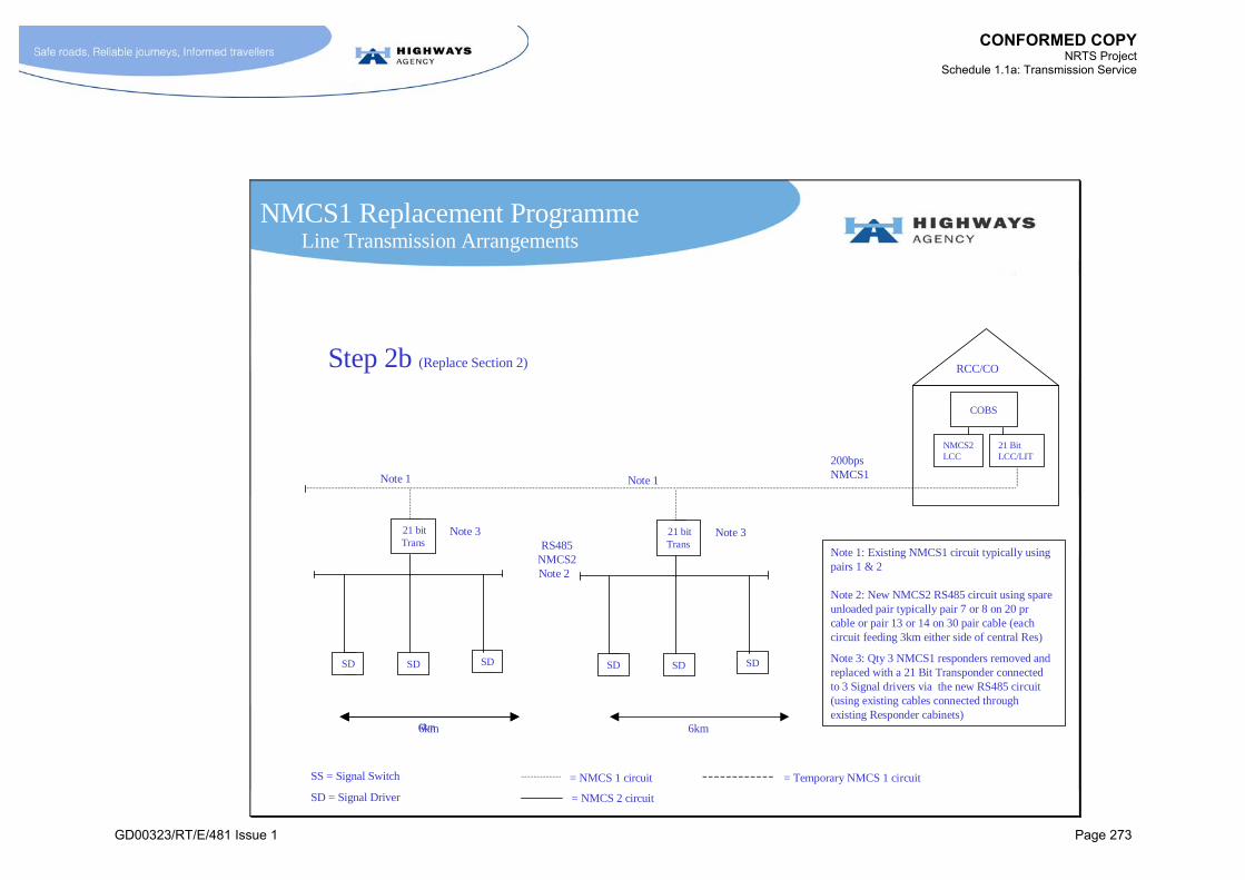
CONFORMED COPY NRTS Project
Schedule 1.1a: Transmission Service
GD00323/RT/E/481 Issue 1 Page 273
NMCS1 Replacement Programme
RCC/CO
200bps NMCS1
RS485 NMCS2
6km6km
Step 2b (Replace Section 2)
Note 1: Existing NMCS1 circuit typically using pairs 1 & 2
Note 2: New NMCS2 RS485 circuit using spare unloaded pair typically pair 7 or 8 on 20 pr cable or pair 13 or 14 on 30 pair cable (each circuit feeding 3km either side of central Res)
Note 3: Qty 3 NMCS1 responders removed and replaced with a 21 Bit Transponder connected to 3 Signal drivers via the new RS485 circuit (using existing cables connected through existing Responder cabinets)
COBS
21 BitLCC/LIT
NMCS2LCC
SS = Signal Switch
SD = Signal Driver
= NMCS 1 circuit
= NMCS 2 circuit
= Temporary NMCS 1 circuit
Note 1
Note 2
6km
Note 1
Line Transmission Arrangements
21 bitTrans
SDSDSD
Note 321 bitTrans
SDSDSD
Note 3

CONFORMED COPY NRTS Project
Schedule 1.1a: Transmission Service
GD00323/RT/E/481 Issue 1 Page 274
NMCS1 Replacement Programme
RCC/CO
200bps NMCS1
6km6km
Step 3 (Switch To Temporary Data pairs)
Note 1: Existing NMCS1 circuits (Pairs 1&2) decommissioned and reconnected to NMCS2 HDLC V26.
Note 2: New NMCS2 RS485 circuit using spare unloaded pair typically pair 7 or 8 on 20 pr cable or pair 13 or 14 on 30 pair cable (each circuit feeding 3km either side of central Res)
Note 3: Qty 3 NMCS1 responders removed and replaced with a 21 Bit Transponder connected to 3 Signal drivers via RS485
Note 4: Temporary NMCS1 200 bps circuit provided using existing phone lines (amplified 88mH loaded pairs). The period the system is in this state to be minimised as PCO/RCC will be running on a reduced telephone service.
COBS
21 BitLCC/LIT
NMCS2LCC
SS = Signal Switch
SD = Signal Driver
= NMCS 1 circuit
= NMCS 2 circuit
= Temporary NMCS 1 circuit
Note 4
6km
Note 4
Prerequisites
Step 2 continues until a complete section of NMCS1 Responders has been replaced with 21 Bit Interfaces
Site Data Tested and Ready
Note 1HDLC V26 NMCS2
Line Transmission Arrangements
RS485 NMCS2
Note 2
21 bitTrans
SDSDSD
Note 321 bitTrans
SDSDSD
Note 3

CONFORMED COPY NRTS Project
Schedule 1.1a: Transmission Service
GD00323/RT/E/481 Issue 1 Page 275
NMCS1 Replacement Programme
COBS
RCC/CO
NMCS2 LCC
RS485 NMCS2
6km6km
Step 4 (Completion)
Note 4
Note 5: In one operation, all 21 Bit Transponders will be removed and replaced with standard transponders connected to the new NMCS2 HDLC circuits on pairs 1&2
Note 6: 88mH pairs used as temporary circuit for 21 bit transponder revert back to being used for phone lines
SS = Signal Switch
SD = Signal Driver
= NMCS 1 circuit
= NMCS 2 circuit
= Temporary NMCS 1 circuit
Note 6
Note 5Note 5
Line Transmission Arrangements
ST
SDSDSD
ST
SDSDSD
HDLC V26 NMCS2
CONFORMED COPY NRTS Project
Schedule 1.1a: Transmission Service
GD00323/RT/E/481 Issue 1 Page 276
L ANNEX L
NRTS NETWORK CAPACITY RESERVED FOR COMMERCIAL SERVICES

CONFORMED COPY NRTS Project
Schedule 1.1a: Transmission Service
GD00323/RT/E/481 Issue 1 Page 277
L.1 INTRODUCTION
L.1.1.1 M This Annex identifies the network capacity that is to be reserved for NRTS Co’s commercial services.
L.1.1.2 M No capacity shall be reserved for NRTS Co’s commercial services.


CONFORMED COPY NRTS Project
Schedule 1.1a: Transmission Service
GD00323/RT/E/481 Issue 1 Page 279
M ANNEX M
OUTAGE TRIGGERS

CONFORMED COPY NRTS Project
Schedule 1.1a: Transmission Service
GD00323/RT/E/481 Issue 1 Page 280
M.1 OUTAGE TRIGGERS
M.1.1 Introduction
M.1.1.1 M Outage Triggers shall be as defined in Table M.1-1.
M.1.1.2 M The Outage Triggers are supported by a set of Outage Proxies. An Outage Proxy is a network performance attribute which is causally linked to an STI’s Performance Requirements (for example, in the manner that queue length is a proxy for latency in packet switched network). Such Outage Proxies shall be agreed in detail during the Get Consent to Service Solution process. [An outline version shall be provided by Genesys by the Execution Date.]
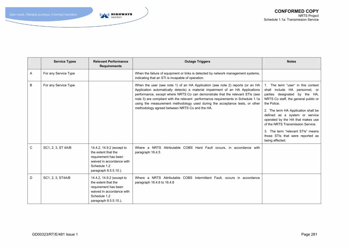
CONFORMED COPY NRTS Project
Schedule 1.1a: Transmission Service
GD00323/RT/E/481 Issue 1 Page 281
Service Types Relevant Performance Requirements
Outage Triggers Notes
A For any Service Type When the failure of equipment or links is detected by network management systems, indicating that an STI is incapable of operation.
B For any Service Type When the user (see note 1) of an HA Application (see note 2) reports (or an HA Application automatically detects) a material impairment of an HA Applications performance, except where NRTS Co can demonstrate that the relevant STIs (see note 3) are compliant with the relevant performance requirements in Schedule 1.1a using the measurement methodology used during the acceptance tests, or other methodology agreed between NRTS Co and the HA.
1. The term “user“ in this context shall include HA personnel, or parties designated by the HA, NRTS Co staff, the general public or the Police.
2. The term HA Application shall be defined as a system or service operated by the HA that makes use of the NRTS Transmission Service.
3. The term “relevant STIs” means those STIs that were reported as being affected.
C SC1, 2, 3, ST 4A/B 14.4.2, 14.9.2 (except to the extent that the requirement has been waived in accordance with Schedule 1.2 paragraph 8.5.5.10.),
Where a NRTS Attributable COBS Hard Fault occurs, in accordance with paragraph 16.4.5
D SC1, 2, 3, ST4A/B 14.4.2, 14.9.2 (except to the extent that the requirement has been waived in accordance with Schedule 1.2 paragraph 8.5.5.10.),
Where a NRTS Attributable COBS Intermittent Fault, occurs in accordance paragraph 16.4.6 to 16.4.8
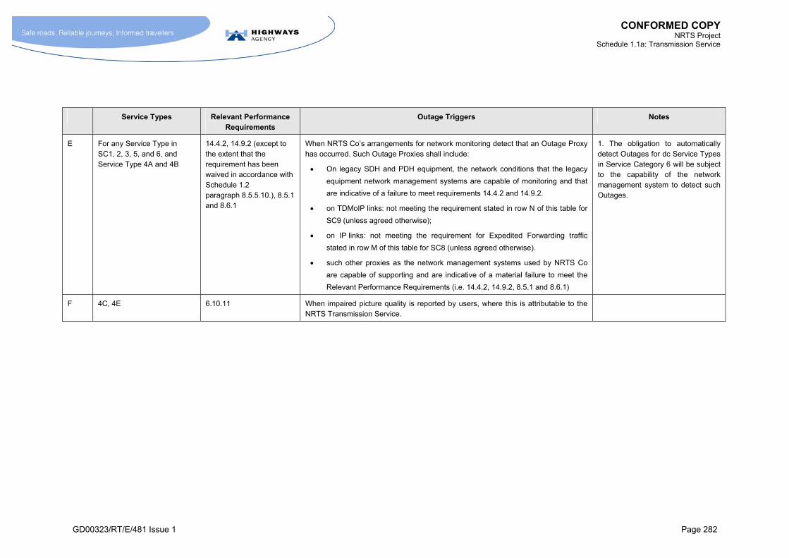
CONFORMED COPY NRTS Project
Schedule 1.1a: Transmission Service
GD00323/RT/E/481 Issue 1 Page 282
Service Types Relevant Performance Requirements
Outage Triggers Notes
E For any Service Type in SC1, 2, 3, 5, and 6, and Service Type 4A and 4B
14.4.2, 14.9.2 (except to the extent that the requirement has been waived in accordance with Schedule 1.2 paragraph 8.5.5.10.), 8.5.1 and 8.6.1
When NRTS Co’s arrangements for network monitoring detect that an Outage Proxy has occurred. Such Outage Proxies shall include:
On legacy SDH and PDH equipment, the network conditions that the legacy
equipment network management systems are capable of monitoring and that
are indicative of a failure to meet requirements 14.4.2 and 14.9.2.
on TDMoIP links: not meeting the requirement stated in row N of this table for
SC9 (unless agreed otherwise);
on IP links: not meeting the requirement for Expedited Forwarding traffic
stated in row M of this table for SC8 (unless agreed otherwise).
such other proxies as the network management systems used by NRTS Co
are capable of supporting and are indicative of a material failure to meet the
Relevant Performance Requirements (i.e. 14.4.2, 14.9.2, 8.5.1 and 8.6.1)
1. The obligation to automatically detect Outages for dc Service Types in Service Category 6 will be subject to the capability of the network management system to detect such Outages.
F 4C, 4E 6.10.11 When impaired picture quality is reported by users, where this is attributable to the NRTS Transmission Service.
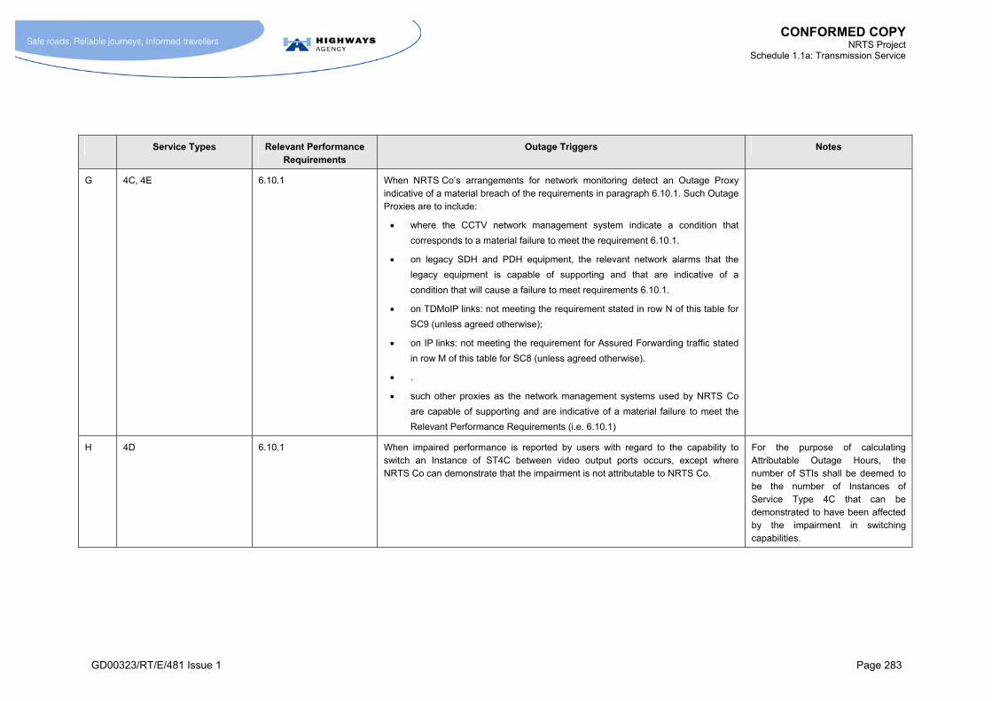
CONFORMED COPY NRTS Project
Schedule 1.1a: Transmission Service
GD00323/RT/E/481 Issue 1 Page 283
Service Types Relevant Performance Requirements
Outage Triggers Notes
G 4C, 4E 6.10.1 When NRTS Co’s arrangements for network monitoring detect an Outage Proxy indicative of a material breach of the requirements in paragraph 6.10.1. Such Outage Proxies are to include:
where the CCTV network management system indicate a condition that
corresponds to a material failure to meet the requirement 6.10.1.
on legacy SDH and PDH equipment, the relevant network alarms that the
legacy equipment is capable of supporting and that are indicative of a
condition that will cause a failure to meet requirements 6.10.1.
on TDMoIP links: not meeting the requirement stated in row N of this table for
SC9 (unless agreed otherwise);
on IP links: not meeting the requirement for Assured Forwarding traffic stated
in row M of this table for SC8 (unless agreed otherwise).
.
such other proxies as the network management systems used by NRTS Co
are capable of supporting and are indicative of a material failure to meet the
Relevant Performance Requirements (i.e. 6.10.1)
H 4D 6.10.1 When impaired performance is reported by users with regard to the capability to switch an Instance of ST4C between video output ports occurs, except where NRTS Co can demonstrate that the impairment is not attributable to NRTS Co.
For the purpose of calculating Attributable Outage Hours, the number of STIs shall be deemed to be the number of Instances of Service Type 4C that can be demonstrated to have been affected by the impairment in switching capabilities.

CONFORMED COPY NRTS Project
Schedule 1.1a: Transmission Service
GD00323/RT/E/481 Issue 1 Page 284
Service Types Relevant Performance Requirements
Outage Triggers Notes
I 4D 6.10.1 To the extent permitted by the network management capabilities of the legacy equipment at each RMC Area Take-On Date in respect of the Transmission Service, when the network management arrangements detect an Outage Proxy condition that indicates that the requirements in paragraph 6.10.1are materially not satisfied.
J SC5 7.8.8 Subject to the capabilities of the network management system at each RMC Area Take-On Date in respect of the Transmission Service, when the following conditions are detected:
the failure of an STI;
a material impairment in the performance of an STI.
K SC6 8.5.1 and 8.6.1 See Row E.
L SC7 Not applicable
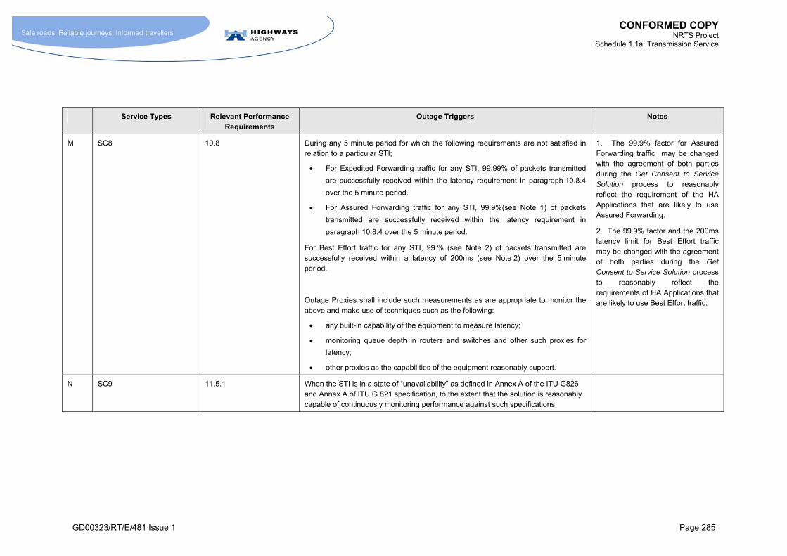
CONFORMED COPY NRTS Project
Schedule 1.1a: Transmission Service
GD00323/RT/E/481 Issue 1 Page 285
Service Types Relevant Performance Requirements
Outage Triggers Notes
M SC8 10.8 During any 5 minute period for which the following requirements are not satisfied in relation to a particular STI;
For Expedited Forwarding traffic for any STI, 99.99% of packets transmitted
are successfully received within the latency requirement in paragraph 10.8.4
over the 5 minute period.
For Assured Forwarding traffic for any STI, 99.9%(see Note 1) of packets
transmitted are successfully received within the latency requirement in
paragraph 10.8.4 over the 5 minute period.
For Best Effort traffic for any STI, 99.% (see Note 2) of packets transmitted are successfully received within a latency of 200ms (see Note 2) over the 5 minute period.
Outage Proxies shall include such measurements as are appropriate to monitor the above and make use of techniques such as the following:
any built-in capability of the equipment to measure latency;
monitoring queue depth in routers and switches and other such proxies for
latency;
other proxies as the capabilities of the equipment reasonably support.
1. The 99.9% factor for Assured Forwarding traffic may be changed with the agreement of both parties during the Get Consent to Service Solution process to reasonably reflect the requirement of the HA Applications that are likely to use Assured Forwarding.
2. The 99.9% factor and the 200ms latency limit for Best Effort traffic may be changed with the agreement of both parties during the Get Consent to Service Solution process to reasonably reflect the requirements of HA Applications that are likely to use Best Effort traffic.
N SC9 11.5.1 When the STI is in a state of “unavailability” as defined in Annex A of the ITU G826 and Annex A of ITU G.821 specification, to the extent that the solution is reasonably capable of continuously monitoring performance against such specifications.

CONFORMED COPY NRTS Project
Schedule 1.1a: Transmission Service
GD00323/RT/E/481 Issue 1 Page 286
Service Types Relevant Performance Requirements
Outage Triggers Notes
O SC9 11.5.1 When an Outage Proxy occurs. Outage Proxies shall include:
on IP links: not meeting the requirement for Expedited Forwarding traffic in
row M of this table for SC8 (unless agreed otherwise).
. such other proxies as the network management systems used by NRTS Co
are capable of supporting and are indicative of a material failure to meet the
Relevant Performance Requirements (i.e. 11.5.1)
P ST 10Ax or 10Bx; picture quality
12.13.1 When a discernable impairment in picture quality delivered to users is reported, except where NRTS Co can demonstrate that the STI meets the performance requirements in 12.13.1 using the measurement methodology used during the acceptance tests, or other methodology agreed between NRTS Co and the HA.
Q ST 10Ax or 10Bx; picture quality
12.13.1 When an Outage Proxy condition occurs.
Such Outage Proxies shall include:
on IP links: not meeting the requirement for Assured Forwarding traffic stated
in row M of this table for SC8 (unless agreed otherwise).
such other proxies as the network management systems used by NRTS Co
are capable of supporting and are indicative of a material failure to meet the
Relevant Performance Requirements (i.e. 12.13.1)
R ST 10Ax,Bx; video path latency
12.22.10 When it is reported by users that the apparent delay between moving the PTZ control and the image displayed in the monitor responding has materially deteriorated, except where NRTS Co can demonstrate that this is not due to a failure to comply with requirements in Schedule 1.1a paragraph 12.22.10.
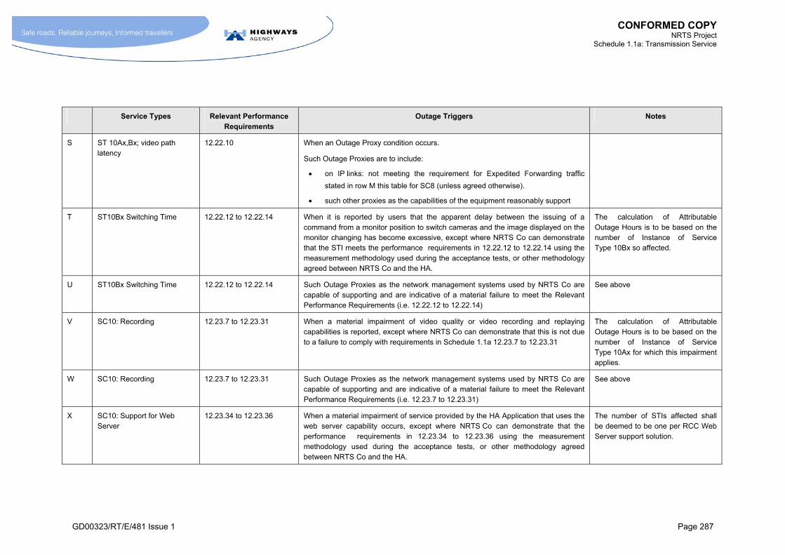
CONFORMED COPY NRTS Project
Schedule 1.1a: Transmission Service
GD00323/RT/E/481 Issue 1 Page 287
Service Types Relevant Performance Requirements
Outage Triggers Notes
S ST 10Ax,Bx; video path latency
12.22.10 When an Outage Proxy condition occurs.
Such Outage Proxies are to include:
on IP links: not meeting the requirement for Expedited Forwarding traffic
stated in row M this table for SC8 (unless agreed otherwise).
such other proxies as the capabilities of the equipment reasonably support
T ST10Bx Switching Time 12.22.12 to 12.22.14 When it is reported by users that the apparent delay between the issuing of a command from a monitor position to switch cameras and the image displayed on the monitor changing has become excessive, except where NRTS Co can demonstrate that the STI meets the performance requirements in 12.22.12 to 12.22.14 using the measurement methodology used during the acceptance tests, or other methodology agreed between NRTS Co and the HA.
The calculation of Attributable Outage Hours is to be based on the number of Instance of Service Type 10Bx so affected.
U ST10Bx Switching Time 12.22.12 to 12.22.14 Such Outage Proxies as the network management systems used by NRTS Co are capable of supporting and are indicative of a material failure to meet the Relevant Performance Requirements (i.e. 12.22.12 to 12.22.14)
See above
V SC10: Recording 12.23.7 to 12.23.31 When a material impairment of video quality or video recording and replaying capabilities is reported, except where NRTS Co can demonstrate that this is not due to a failure to comply with requirements in Schedule 1.1a 12.23.7 to 12.23.31
The calculation of Attributable Outage Hours is to be based on the number of Instance of Service Type 10Ax for which this impairment applies.
W SC10: Recording 12.23.7 to 12.23.31 Such Outage Proxies as the network management systems used by NRTS Co are capable of supporting and are indicative of a material failure to meet the Relevant Performance Requirements (i.e. 12.23.7 to 12.23.31)
See above
X SC10: Support for Web Server
12.23.34 to 12.23.36 When a material impairment of service provided by the HA Application that uses the web server capability occurs, except where NRTS Co can demonstrate that the performance requirements in 12.23.34 to 12.23.36 using the measurement methodology used during the acceptance tests, or other methodology agreed between NRTS Co and the HA.
The number of STIs affected shall be deemed to be one per RCC Web Server support solution.
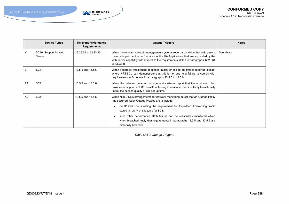
CONFORMED COPY NRTS Project
Schedule 1.1a: Transmission Service
GD00323/RT/E/481 Issue 1 Page 288
Service Types Relevant Performance Requirements
Outage Triggers Notes
Y SC10: Support for Web Server
12.23.34 to 12.23.36 When the relevant network management systems report a condition that will cause a material impairment in performance of the HA Applications that are supported by the web server capability with respect to the requirements stated in paragraphs 12.23.34 to 12.23.36.
See above
Z SC11 13.5.5 and 13.5.6 When a material impairment of speech quality or call set-up time is reported, except where NRTS Co can demonstrate that this is not due to a failure to comply with requirements in Schedule 1.1a paragraphs 13.5.5 to 13.5.6.
AA SC11 13.5.5 and 13.5.6 When the relevant network management systems report that the equipment that provides or supports SC11 is malfunctioning in a manner that it is likely to materially impair the speech quality or call set-up time.
AB SC11 13.5.5 and 13.5.6 When NRTS Co’s arrangements for network monitoring detect that an Outage Proxy has occurred. Such Outage Proxies are to include:
on IP links: not meeting the requirement for Expedited Forwarding traffic
stated in row M of this table for SC8.
such other performance attributes as can be reasonably monitored which
when breached imply that requirements in paragraphs 13.5.5 and 13.5.6 are
materially breached.
Table M.1-1 Outage Triggers